US5991692A - Zero motion detection system for improved vehicle navigation system - Google Patents
Zero motion detection system for improved vehicle navigation systemDownload PDFInfo
- Publication number
- US5991692A US5991692AUS08/579,903US57990395AUS5991692AUS 5991692 AUS5991692 AUS 5991692AUS 57990395 AUS57990395 AUS 57990395AUS 5991692 AUS5991692 AUS 5991692A
- Authority
- US
- United States
- Prior art keywords
- zero
- zero motion
- motion
- gps
- motion state
- Prior art date
- Legal status (The legal status is an assumption and is not a legal conclusion. Google has not performed a legal analysis and makes no representation as to the accuracy of the status listed.)
- Expired - Lifetime
Links
- 238000001514detection methodMethods0.000titleclaimsdescription28
- 238000005259measurementMethods0.000claimsabstractdescription26
- 238000000034methodMethods0.000claimsabstractdescription17
- 238000012935AveragingMethods0.000claimsdescription5
- 239000013598vectorSubstances0.000abstractdescription9
- 238000006073displacement reactionMethods0.000abstractdescription6
- 230000001902propagating effectEffects0.000abstract1
- 230000001133accelerationEffects0.000description31
- 238000012937correctionMethods0.000description9
- 230000008859changeEffects0.000description8
- 238000010586diagramMethods0.000description5
- 230000008901benefitEffects0.000description4
- 238000013459approachMethods0.000description3
- 238000011161developmentMethods0.000description3
- 238000012986modificationMethods0.000description3
- 230000004048modificationEffects0.000description3
- 241000238876AcariSpecies0.000description2
- 230000000694effectsEffects0.000description2
- 230000010354integrationEffects0.000description2
- 238000013507mappingMethods0.000description2
- 238000004891communicationMethods0.000description1
- 238000013480data collectionMethods0.000description1
- 230000007123defenseEffects0.000description1
- 230000001934delayEffects0.000description1
- 230000006870functionEffects0.000description1
- 230000003862health statusEffects0.000description1
- 238000009434installationMethods0.000description1
- 230000003993interactionEffects0.000description1
- 230000007774longtermEffects0.000description1
- 239000011159matrix materialSubstances0.000description1
- 230000010287polarizationEffects0.000description1
- 230000008569processEffects0.000description1
- 238000012545processingMethods0.000description1
- 230000009467reductionEffects0.000description1
- 238000005070samplingMethods0.000description1
- 230000009466transformationEffects0.000description1
Images


Classifications
- G—PHYSICS
- G01—MEASURING; TESTING
- G01C—MEASURING DISTANCES, LEVELS OR BEARINGS; SURVEYING; NAVIGATION; GYROSCOPIC INSTRUMENTS; PHOTOGRAMMETRY OR VIDEOGRAMMETRY
- G01C25/00—Manufacturing, calibrating, cleaning, or repairing instruments or devices referred to in the other groups of this subclass
- G01C25/005—Manufacturing, calibrating, cleaning, or repairing instruments or devices referred to in the other groups of this subclass initial alignment, calibration or starting-up of inertial devices
- G—PHYSICS
- G01—MEASURING; TESTING
- G01C—MEASURING DISTANCES, LEVELS OR BEARINGS; SURVEYING; NAVIGATION; GYROSCOPIC INSTRUMENTS; PHOTOGRAMMETRY OR VIDEOGRAMMETRY
- G01C21/00—Navigation; Navigational instruments not provided for in groups G01C1/00 - G01C19/00
- G01C21/26—Navigation; Navigational instruments not provided for in groups G01C1/00 - G01C19/00 specially adapted for navigation in a road network
- G01C21/28—Navigation; Navigational instruments not provided for in groups G01C1/00 - G01C19/00 specially adapted for navigation in a road network with correlation of data from several navigational instruments
- G—PHYSICS
- G01—MEASURING; TESTING
- G01P—MEASURING LINEAR OR ANGULAR SPEED, ACCELERATION, DECELERATION, OR SHOCK; INDICATING PRESENCE, ABSENCE, OR DIRECTION, OF MOVEMENT
- G01P13/00—Indicating or recording presence, absence, or direction, of movement
- G—PHYSICS
- G01—MEASURING; TESTING
- G01P—MEASURING LINEAR OR ANGULAR SPEED, ACCELERATION, DECELERATION, OR SHOCK; INDICATING PRESENCE, ABSENCE, OR DIRECTION, OF MOVEMENT
- G01P21/00—Testing or calibrating of apparatus or devices covered by the preceding groups
- G—PHYSICS
- G01—MEASURING; TESTING
- G01P—MEASURING LINEAR OR ANGULAR SPEED, ACCELERATION, DECELERATION, OR SHOCK; INDICATING PRESENCE, ABSENCE, OR DIRECTION, OF MOVEMENT
- G01P21/00—Testing or calibrating of apparatus or devices covered by the preceding groups
- G01P21/02—Testing or calibrating of apparatus or devices covered by the preceding groups of speedometers
Definitions
- the present inventionrelates generally to vehicle navigation systems. More particularly, the present invention relates to an improved vehicle navigation system and method for error reduction at low or no vehicle speed.
- NAVSTARNavigation Satellite Timing and Ranging
- DoDU.S. Department of Defense
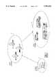
- the GPS systemconsists of three major segments: Space, Control, and User as illustrated in FIG. 1.
- the space segmentconsists of a nominal constellation of 24 operational satellites which have been placed in 6 orbital planes above the Earth's surface.
- the satellitesare in circular orbits in an orientation which normally provides a GPS user with a minimum of five satellites in view from any point on Earth at any one time.
- Each satellitecontinuously broadcasts navigation data.
- This navigation datawhich is computed and controlled by the GPS Control Segment, includes the satellite's time, its clock correction and ephemeris parameters, almanacs, and health status for all GPS satellites. From this information, the user computes the satellite's precise position and clock offset.
- the controlling segmentconsists of a Master Control Station and a number of monitor stations at various locations around the world. Each monitor station tracks all the GPS satellites in view and passes the signal measurement data back to the Master Control Station. There, computations are performed to determine precise satellite ephemeris and satellite clock errors.
- the Master Control Stationgenerates the upload of user navigation data from each satellite. This data is subsequently rebroadcast by the satellite as part of its navigation data message.
- the user segmentis the collection of all GPS receivers and their application support equipment such as antennas and processors. This equipment allows users to receive, decode, and process the information necessary to obtain accurate position, velocity, and timing measurements.
- GPS based position solutionsare inherently poor under low vehicle dynamics.
- Some current systemsuse a hard wired speed signal or odometer input to help correct or calibrate distance errors under low or zero speed conditions. This hard wired approach increases the overall system cost, requires specialized knowledge of the vehicle's wiring system, and requires a specialized wiring harness to interface to each individual automobile.
- certain systemsrequire a calibration procedure to determine the zero offset of the motion sensor. For example, in a system using a compass or gyro, the user must press a calibration button and drive in a circle and come to a stop for a minimum period of time to determine zero offsets for those devices.
- the systemcan calculate the zero offset for the gyro. Odometers were previously used for zero motion but are generally ambiguous below 3 mph and also required hard wiring. Other systems require a rotational sensor to determine a vehicle's change in heading under these low dynamic or other unfavorable GPS conditions.
- the zero motion detection system for an improved vehicle navigation systemcan take advantage of the recent availability of low cost micro-machined and piezoelectric sensors, and partially overcomes the low dynamics and line of sight limitations of GPS receivers without resorting to the hard wired approach described above.
- the sensorsintroduce system level errors due to their inherent DC offset and drift rates.
- the improved vehicle navigation systemminimizes both the sensor induced errors and GPS low dynamic limitations by using a zero motion detection system as a self contained (within the navigation system), vehicle independent device.
- the zero motion detection systemallows recalibration of zero offsets at every zero motion state, and provides a true zero velocity indicator. Furthermore, the system enhances portability by eliminating the need for the hard-wired approach.
- the sensors described aboveprovide an analog output proportional to either acceleration (micro-machined accelerometer), or rate of rotation (piezoelectric gyro) with a DC offset voltage.
- This offset voltagegreatly affects the accuracy of the measurement.
- This offset voltageis also affected by temperature, vehicle load, and physical mounting of device in relation to the vehicle.
- the improved vehicle navigation systemaverages the sensor's readings to use as the DC offset voltage for this sensor.
- the improved vehicle navigation systempasses a zero motion signal to the GPS based positioning engine that indicates a zero motion state.
- the positioning enginecan use this information to lock heading changes and calibrate velocity measurements.
- the improved vehicle navigation systemlocks the DC offset measurement gathered during the zero motion state, and the positioning engine is released to update changes in heading and velocity.
- the improved vehicle navigation systemeliminates the "wandering" effect of the GPS position while the vehicle is at rest. This also allows the improved vehicle navigation system to use less expensive amplifier/sensor combinations in high performance navigation systems.
- FIG. 1is a general illustration of the various segments in the NAVSTAR GPS system
- FIG. 2shows variations of an improved vehicle navigation system according to the principles of the present invention
- FIG. 3shows a block/data flow diagram of a version of the improved vehicle navigation system of FIG. 2;
- FIG. 4ashows a block diagram of a zero motion detect system according to the principles of the present invention
- FIG. 4bshows a flow chart for the operation of the zero motion detect system of FIG. 4a;
- FIGS. 5a and 5bshow a general flow chart of the operation of certain embodiments of the improved vehicle navigation system of FIG. 2;
- FIGS. 6a-6dshow general diagrams illustrating how the improved vehicle navigation system updates the heading information with the map heading for position propagations.
- FIG. 2illustrates, in block diagram form, exemplary arrangements of an improved vehicle navigation system 10 for an automobile 12.
- the improved vehicle navigation systemuses GPS signals for position determination.
- the improved vehicle navigation system 10uses a GPS antenna 14 to receive the GPS signals.
- the antenna 14is preferably of right-hand circular polarization, has a gain minimum of -3 dBiC above 5 degree elevation, and has a gain maximum of +6 dBiC. Patch or Helix antennas matching these specifications can be used.
- the GPS antenna 14can be connected to a preamplifier 16 to amplify the GPS signals received by the antenna 14.
- the pre-amplifier 16is optional, and the GPS antenna can be directly connected to a GPS receiver 16.
- the GPS receiver 18continuously determines geographic position by measuring the ranges (the distance between a satellite with known coordinates in space and the receiver's antenna) of several satellites and computing the geometric intersection of these ranges. To determine a range, the receiver 18 measures the time required for the GPS signal to travel from the satellite to the receiver antenna. The timing code generated by each satellite is compared to an identical code generated by the receiver 18. The receiver's code is shifted until it matches the satellite's code. The resulting time shift is multiplied by the speed of light to arrive at the apparent range measurement.
- the resulting range measurementcontains propagation delays due to atmospheric effects, and satellite and receiver clock errors, it is referred to as a "pseudorange.” Changes in each of these pseudoranges over a short period of time are also measured and processed by the receiver 18. These measurements, referred to as delta range measurements or “delta-pseudoranges,” are used to compute velocity. Delta ranges are in meters per second which are calculated by the receiver from pseudoranges, and the GPS receiver 18 can track the carrier phase of the GPS signals to smooth out the psuedoranges. The velocity and time data is generally computed once a second. If one of the position components is known, such as altitude, only three satellite pseudorange measurements are needed for the receiver 16 to determine its velocity and time. In this case, only three satellites need to be tracked.
- the GPS receiver 18provides GPS measurements to an application unit 22.
- the application unit 22consists of application processing circuitry 24, such as a processor, memory, busses, the application software and related circuitry, and interface hardware 26.
- the application unit 22can be incorporated into the GPS receiver 18.
- the interface hardware 26integrates the various components of the vehicle navigation system 10 with the application unit 22.
- the system 10can include a combination of the features, such as those shown in dashed lines.
- the improved vehicle navigation systemcould rely upon information provided by the GPS receiver 18, an accelerometer 28 (which in certain embodiments is an orthogonal axes accelerometer) and the map database 30 to propagate vehicle position.
- the improved vehicle navigation system 10uses the accelerometer 28, an odometer 29 and a map database 30 according to other aspects of the present invention.
- Other embodimentscan include a speed sensor 34, a heading sensor 36, such as a gyro, compass or differential odometer, and a one or two way communication link 38.
- Other configurations and combinationsare possible which incorporate aspects of the present invention as would be understood by one of ordinary skill in the art.
- the improved vehicle navigation systemcan be incorporated in an advanced driver information system which controls and provides information on a variety of automobile functions.
- FIG. 3shows a block and data flow diagram for the improved vehicle navigation system 10 which reveals the flexibility and accuracy of certain embodiments of the improved vehicle navigation system.
- the GPS receiver 18provides position information, velocity information, psuedoranges and delta pseudoranges to the sensor integrator 40.
- the sensor integrator 40uses the velocity information to determine a current position for the vehicle. In this embodiment, if GPS velocity information is not available, the sensor integrator 40 can calculate GPS velocity using the available delta range measurements to determine a current position. GPS velocity information is derived from a set of delta range measurements, and if only a subset of delta range measurements is available, the vehicle navigation system can derive GPS velocity information from the subset of delta range measurements.
- the vehicle navigation systemuses the GPS position information at start-up as a current position and as a check against the current position. If the current position fails the check, then the GPS position can replace the current position.
- GPS velocity informationis not available, certain embodiments can obtain the information used to propagate the vehicle position from the sensors.
- the sensor 28,which is a multiple axis accelerometer, provides acceleration information for at least two orthogonal axes (lateral, longitudinal and/or vertical) to the application unit 22.
- the odometer 29provides information which can be used in place of the information derived from the accelerometers.
- Other available informationcan include the odometer distance and GPS heading, a distance calculation and map heading, the GPS speed information and map heading, gyro heading and longitudinal speed and other variations.
- a map database 30stores map information, such as a road network, and provides map information to the application unit 22.
- the map databaseshould have some level of known accuracy, confidence, or defined error.
- every change in street segment headingis designated as a shape point which has a heading with a fixed measurement error.
- a user interface 32which includes a display and keyboard, allows interaction between the user and the improved vehicle navigation system 10. In this embodiment, if the difference between the current heading and map heading is less than a threshold value, then the map heading is used as the heading.
- Vehicle positioning 22calibrates v a from v G when possible. The GPS position information is used as an overall check on the current position.
- the sensor integrator 40provides the current position and a velocity (speed and heading) to a map matching block 42.
- the map matching block 42provides road segment information for the road segment that the vehicle is determined to be travelling on, such as heading, and a suggested position.
- the sensor integrator 40can update the heading component of the velocity information with the heading provided by the map matching block 42 to update the current position. If the map matching block 42 indicates a good match, then the map matched position can replace the current position. If not, the sensor integrator propagates the previous position to the current position using the velocity information. As such, the sensor integrator 40 determines the current position and provides the current position to a user interface and/or route guidance block 46.
- the map matching block 42also provides correction data, such as a distance scale factor and/or offset and a turn rate scale factor and/or offset, to a sensor calibration block 44.
- the sensor integrator 40also provides correction data to the sensor calibration block 44.
- the correction data from the sensor integrator 40is based on the GPS information. Thus, accurate correction data based on the GPS information is continuously available to calibrate the sensors 28 (2 or 3 axis accelerometer) as well as for other sensors 29, 34 and 36 depending on the particular embodiment.
- the correction data from the map matching blockmay be ignored by the sensor calibration block 44 until a good match is found between the map information and the current position. If a highly accurate match is found by map matching 42, most likely after a significant maneuver such as a change in direction, the map matched position is used as a reference point or starting position for position propagation according to the principles of the present invention.
- the sensor calibration block 44contains the sensor calibration parameters, such as scale factors and zero factors for the sensors 28 and 29 and provides the calibration parameters to the sensor integrator 40 to calibrate the sensors 28-36.
- the systemcan combine the sensor integrator 40 and sensor calibration 44 into GPS engine 18 using its processor.
- the route guidance and user interface, the sensor integrator 40 and the sensor calibration 44is performed on an application specific integrated circuit (ASIC).
- ASICapplication specific integrated circuit
- the improved vehicle navigation system 10can update the current position with the known position. After the vehicle has moved a distance from the known position which is now a previous position, the improved vehicle navigation system must accurately propagate the vehicle position from the previous position to the current position.
- the vehicle positionwill be reported in geodetic coordinates (latitude, longitude, altitude).
- the non-GPS datawill be provided in body or platform coordinates.
- the GPS velocities and the equations used for velocity propagation of positionwill take place in the North, East, Down frame.
- the geodetic frameis a representation of the Earth Centered Earth Fixed (ECEF) coordinates that is based on spherical trigonometry. This is the coordinate frame that the mapping database uses. Its units are degrees and meters displacement in height above the geoid. These coordinates will be with respect to the WGS-84 Earth model, which is the Earth model used by the Global Positioning System (GPS). This is mathematically equivalent to the North American Datum 1983 (NAD 83) system which the mapping database is referenced to.
- the North East Down frameis a right-handed orthonormal coordinate system fixed to the vehicle with its axes pointing to the True North, True East, and True Down (perpendicular to the Earth) directions.
- the body coordinatesform a right-handed orthonormal coordinate system with their origin at the navigation unit, the x axis pointing toward the nose of the vehicle, the right axis pointing out the right door of the vehicle and the z axis pointing down perpendicular to the Earth.
- xposition vector [latitude longitude altitude]
- C N BTransformation matrix which rotates a vector from the Body coordinate frame to the North East Down coordinate frame.
- t-2time of data set before t-1
- t-1 and t-2do not necessarily imply a one second difference, but only data collection and/or data validity times.
- GGeodetic (latitude longitude height)
- the steady state position propagation equationis based on the physical definition of velocity and acceleration.
- the current positionis equal to the previous position plus the integral of velocity plus the double integral of acceleration. ##EQU2##
- the velocity computed from the odometercounts from time t-2 to time t-1.
- the current positionis equal to the previous position plus the GPS velocity (vector) times the delta time plus the GPS acceleration from two time periods ago minus the Accelerometer acceleration from two time periods ago (a correction factor) plus the Accelerometer acceleration from the current second.
- other sensor informationsuch as the odometer information, can be used in the above equations if it is determined to be more appropriate than the accelerometer information.
- each sensorneeds to have calibrations performed on it.
- the calibrationswill be performed using known good data from the GPS receiver 18.
- the GPS receiver 18has velocity accuracy to within one meter per second.
- the GPS velocity informationbecomes less accurate in low velocity states of less than 1.5 m/s.
- the GPS velocity informationis time tagged so that it matches a particular set of odometer and accelerometer data on a per second basis. Map matching provides correction factors, but they are based on long term trends and not directly associated with any specify time interval.
- Sensor calibration using the GPS velocitieswill involve the following sensors in this particular embodiment.
- OdometerVehicle Speed Sensor Calibration.
- the odometer outputis the number of ticks of a counter, with a specified number of ticks to be equal to one unit of linear distance traversed.
- An exampleis that the GM Vehicle Speed Sensor has 4000 pulses per mile. This will have a default value from the factory and a calibrated value stored in FLASH thereafter.
- the odometerwill be calibrated once per second from the GPS velocity and acceleration that occurred over that same time period, when valid GPS data is available.
- the Lateral Accelerometermeasures centripetal acceleration. It is used to compute turn angle from the equation: Turn angle in radians is equal to the quotient of centripetal acceleration and tangential velocity.
- the Lateral accelerometerhas two values which need to be calibrated: The zero offset and the scale factor.
- the zero offsetis the measurement that the accelerometer outputs when a no acceleration state exists.
- the scale factoris the number that is multiplied by the difference between the accelerometer read value and the accelerometer zero offset to compute the number of G's of acceleration.
- the first derivative of the GPS velocitieswill be used to compute the scale factor calibration.
- the zero motion detect systemwhich is discussed in FIGS. 4a and 4b will be used to compute the accelerometer zero offset value.
- the longitudinal accelerometermeasures the acceleration along the nose/tail axis of the vehicle, with a positive acceleration being out the nose (forward) and a negative acceleration being out the rear of the vehicle.
- the Longitudinal accelerometerhas two values which need to be calibrated: The zero offset and the scale factor.
- the zero offsetis the measurement that the accelerometer outputs when an no acceleration state exists.
- the scale factoris the number that is multiplied by the difference between the accelerometer read value and the accelerometer zero offset to compute the number of G's of acceleration.
- the first derivative of the GPS velocitieswill be used to compute the scale factor calibration.
- the zero motion detect system shown in FIGS. 4a and 4bwill be used to compute the accelerometer zero offset value.
- FIG. 4ashows the zero motion detect system with a motion sensor 64 (an orthogonal axes accelerometer in this embodiment) providing motion signals with an offset.
- An amplifier 65amplifies the motion signals, and in this particular embodiment, the motion signals are digitized in an analog to digital converter 67.
- the motion signalsare provided to a zero motion detection and offset calculation block 69 which is in the application unit 22 (FIG. 2).
- the vehicle navigation systemdetermines a zero motion state by comparing samples of the motion signals from the motion sensor 64, such as an accelerometer, a gyro, or piezoelectric sensors with a threshold (the threshold is determined by vehicle vibration characteristics for the type of vehicle that the unit is mounted in, or the threshold for motion sensor could be set using other sensors which suggest zero motion, such as odometer, GPS or DGPS).
- the vehicle navigation systemuses at least one of the samples to determine the zero offsets if the zero motion state is detected. At least two samples are preferred to compare over a time interval and averaging those samples to obtain a zero offset for the motion sensor 64. If a zero motion state exists, the vehicle navigation system sets a zero motion flag 71 and uses at least one of the samples to determine the zero offset for the sensor providing the processed motion signals.
- the systemalso provides offset data signals 73 which reflect the zero offset for the sensor providing the motion signals or the raw data used to calculate the zero offset.
- the vehicle navigation systemcan resolve ambiguity of low velocity GPS measurements because the velocity is zero. GPS velocities do not go to zero, so ambiguities exist when in a low velocity state of less than 1.5 m/s. If a zero motion flag is on, then the ambiguities are resolved because the system is not moving. As such, the system freezes the heading and can also set the speed component of velocity to zero.
- FIG. 4bshows a flowchart of a variation of the zero motion detect system.
- the systemintializes the variables I and NOISE to zero, and at step 77, the first value of the array is read.
- the counter Iis incremented at step 79, and the system reads the next sample at step 81.
- the systembegins to accumulate the differences between consecutive samples of the motion signals. The system loops through steps 81-87 until all the samples have been read and the difference between consecutive samples accumulated in the variable NOISE. Once all the samples have been read, the system compares the variable NOISE with the threshold value at step 89. If the NOISE variable is greater than the threshold, then the system determines that motion has been detected in step 91.
- the systemsets the zero motion flag and determines that the velocity is zero at step 93.
- the setting of the zero motion flagcan set distance changes to zero, lock the heading and current position. Additionally, at step 95, the system calculates the zero offset for the sensor being sampled.
- the systemis described as sampling the motion signals from one sensor 64, such as one axis of the orthogonal axes accelerometer.
- the motion signals for each of the orthogonal axes of the accelerometeris sampled and zero offsets for each is determined.
- zero offsets, sensor calibration or resolving of ambiguitiescan be accomplished for other sensors using the zero motion detection system according to the principles of the present invention.
- FIGS. 5a and 5bshow a general flowchart illustrating how the improved vehicle navigation system 10 propagates a previous position to a current position.
- the improved vehicle navigation systemdetermines if the vehicle is in a zero motion state as described above. If so, the system, at step 152, sets the change in distance to zero, locks the heading and current position, and calibrates the zero offsets.
- step 154determines if a GPS solution is available. If GPS is available, the system uses the GPS velocity information to determine the current position. As shown in step 156, the system calculates a east and north accelerations as follows:
- the accelerationsare used to calculate east and north displacements as follows:
- the current positionis calculated as follows:
- the systemcalibrates the sensor items, such as the accelerometer scale factors and the odometer distance using information from the equations described above.
- the systemcan keep the sensors well calibrated because calibrating can occur once per second (scale factors) if the vehicle speed is above 1.5 m/s.
- the systemchecks at step 158 whether any GPS measurements are available. If so, the system computes the velocity information from the available subset of delta range measurements at step 160. If, at step 162, the velocity information is good, the system calculates current position using the equations 1-6 at step 64 but without calibrating the acceleration scale factors and the odometer distance in this embodiment. If the GPS velocity is determined not to be good at step 162, the system checks the heading component of the GPS velocity at step 166. If the GPS heading component is determined to be valid, then at step 168, the change in distance is set with the odometer distance, and the heading is set with the GPS heading calculated from the GPS delta range measurements. Alternatively, an odometer is not used, and the distance is derived from the longitudinal acceleration information. With this heading and distance, the system calculates a position (lat, long) at step 170 using the equations as follows:
- the systemdetermines the vehicle position using equations 5 and 6, but calibration is not performed at this point in this embodiment.
- the systemdetermines at step 166 that the GPS heading is not valid (GPS blockage or low velocity) or at step 158 that the GPS measurements are insufficient, the system falls back on the orthogonal axes accelerometer(s) and the odometer in this particular embodiment.
- GPS velocity informationis subject to errors at speeds of less than 1.5 m/s, unless using a more accurate GPS system. For example, in a vehicle navigation system using DGPS, the threshold velocity is lower because of the higher accuracy of the system. As such, the vehicle navigation system proceeds to step 172 to determine the change in distance using lateral and longitudinal acceleration information from the orthogonal axes accelerometer(s).
- the systemcompares the longitudinal distance from the accelerometer with the odometer distance, and if the difference between them exceeds a threshold value, the odometer distance is used at step 176. If the difference is less than the threshold, then the accelerometer distance or the odometer distance can be used for the distance at step 178. As shown in dashed step 173, if an odometer is not used, the distance is derived from the longitudinal acceleration information. Once the change in distance is determined, the system calculates the position at step 180 using the following equations to determine heading as follows:
- the systemuses equations 7 and 8 to determine the east and north distances and equations 5 and 6 to determine position.
- step 182the current position is compared with the GPS position. If the current position is within an acceptable distance (within 100 m for example) from the GPS position, the system determines that the current position is valid at step 184. If not, the system replaces the current position with the GPS position at step 186. At this point, the system sends to a map matching step 188 a position and velocity, which has speed and heading components. Depending on the configuration of the map database 30, other information can be sent to the map matching block 188, such as heading and distance based on the current and previous positions, a current position and figures of merit (FOM) for each.
- FAMcurrent position and figures of merit
- the map matching block 188sends back a map matched current position, distance, heading, FOMs for each and calibration data.
- the map matching block 188interrogates the map database 30 (FIG. 2) to obtain a heading of the mapped path segment which the vehicle is determined to be traversing.
- the map matching block 188updates the heading associated with the current position, which was based on GPS and/or sensor calculations, to obtain an updated current position.
- the map matching block 188uses the map heading to update the heading based on the GPS velocity information, the heading based on the GPS position information of step 186, the heading from the sensors, or the heading based on a current position determined through a combination of GPS and sensor information, such as an embodiment with all raw inputs going into a Kalman filter.
- the vehicle navigation system 10uses GPS velocity information to propagate a previous position 191 to a current position 192 (by adding displacements 194 and 196 obtained from the velocity information (integrated) to the previous position).
- GPS informationif GPS information is not available, the vehicle navigation system uses sensor information to propagate the previous position 191 to current position 192 using heading and distance 198. If the difference between the GPS heading (or current heading from the sensors if GPS is not used) and the map heading is within a threshold, then the map heading is used as the heading for position propagation.
- the vehicle navigation system 10can accomplish this in alternative ways. For example, as shown in FIG.
- the vehicle navigation system 10rotates the GPS velocity vector 200 to align with the map heading 202 if the GPS and map headings are within the threshold and integrates the rotated GPS velocity vector 204 to obtain the displacements 208 and 210.
- the updated current position 206is obtained by applying orthogonal displacements 208 and 210 to the previous position 191.
- the map heading 202can be used as the heading for position propagation to the updated current position 206.
- map headingto update the information obtained from the non-GPS sensors or a combination of GPS and other sensors can be accomplished in a similar manner as would be understood by one of skill in the art.
- the improved vehicle navigation systemcan react differently to the information provided by the map matching block 188.
- the improved vehicle navigation systemprovides several significant advantages, such as flexibility, modularity, and accuracy at a cheaper cost because updating can be performed at a complete stop.
- the principles of the present inventionwhich have been disclosed by way of the above examples and discussion, can be implemented using various navigation system configurations and sensors.
- the improved vehicle navigation systemfor instance, can be implemented without using an odometer connection and obtaining distance information from the accelerometer inputs when GPS is not available to improve portability and installation costs.
- the improved vehicle navigation systemcan obtain dead reckoning information from GPS signals when a full set of GPS measurements is available, and use its sensors when anything less than a full set of GPS signals is available.
Landscapes
- Engineering & Computer Science (AREA)
- Radar, Positioning & Navigation (AREA)
- Remote Sensing (AREA)
- Physics & Mathematics (AREA)
- General Physics & Mathematics (AREA)
- Automation & Control Theory (AREA)
- Manufacturing & Machinery (AREA)
- Navigation (AREA)
- Position Fixing By Use Of Radio Waves (AREA)
- Traffic Control Systems (AREA)
Abstract
Description
e-acc=e-vel-last.e-vel (1)
n-acc=n-vel-last.n-vel (2).
e-dist=(e-vel*Δt)+1/2(e-acc*(Δt).sup.2) (3)
n-dist=(n-vel*Δt)+1/2(n-acc*(Δt).sup.2) (4).
lat=lat+(n-dist*degrees/meter) (5)
long=long+(e-dist*degrees/meter) (6),
e-dist=ΔDist*sin(heading) (7)
n-dist=ΔDist*cos(heading) (8).
speed=ΔDist/Δt (9)
Δθ=a.sub.lat (lateral acceleration)/longitudinal speed(10)
heading=heading+Δθ(modulo 360°) (11).
Claims (17)
Priority Applications (6)
| Application Number | Priority Date | Filing Date | Title |
|---|---|---|---|
| US08/579,903US5991692A (en) | 1995-12-28 | 1995-12-28 | Zero motion detection system for improved vehicle navigation system |
| JP09524604AJP2000502803A (en) | 1995-12-28 | 1996-12-27 | Zero motion detection system for improved vehicle navigation system |
| AT96945965TATE209337T1 (en) | 1995-12-28 | 1996-12-27 | ZERO MOTION DETECTION SYSTEM FOR IMPROVED VEHICLE NAVIGATION SYSTEM |
| DE69617269TDE69617269T2 (en) | 1995-12-28 | 1996-12-27 | ZERO MOTION DETECTION SYSTEM FOR IMPROVED VEHICLE NAVIGATION SYSTEM |
| PCT/US1996/020854WO1997024584A1 (en) | 1995-12-28 | 1996-12-27 | A zero motion detection system for improved vehicle navigation system |
| EP96945965AEP0870175B1 (en) | 1995-12-28 | 1996-12-27 | A zero motion detection system for improved vehicle navigation system |
Applications Claiming Priority (1)
| Application Number | Priority Date | Filing Date | Title |
|---|---|---|---|
| US08/579,903US5991692A (en) | 1995-12-28 | 1995-12-28 | Zero motion detection system for improved vehicle navigation system |
Publications (1)
| Publication Number | Publication Date |
|---|---|
| US5991692Atrue US5991692A (en) | 1999-11-23 |
Family
ID=24318820
Family Applications (1)
| Application Number | Title | Priority Date | Filing Date |
|---|---|---|---|
| US08/579,903Expired - LifetimeUS5991692A (en) | 1995-12-28 | 1995-12-28 | Zero motion detection system for improved vehicle navigation system |
Country Status (6)
| Country | Link |
|---|---|
| US (1) | US5991692A (en) |
| EP (1) | EP0870175B1 (en) |
| JP (1) | JP2000502803A (en) |
| AT (1) | ATE209337T1 (en) |
| DE (1) | DE69617269T2 (en) |
| WO (1) | WO1997024584A1 (en) |
Cited By (59)
| Publication number | Priority date | Publication date | Assignee | Title |
|---|---|---|---|---|
| US6263343B1 (en)* | 1996-01-11 | 2001-07-17 | Sony Corporation | System for providing and linking regularity updated map data with data related to the map |
| US6282496B1 (en)* | 1999-10-29 | 2001-08-28 | Visteon Technologies, Llc | Method and apparatus for inertial guidance for an automobile navigation system |
| US20020022924A1 (en)* | 2000-03-07 | 2002-02-21 | Begin John David | Propagation of position with multiaxis accelerometer |
| US6374163B1 (en)* | 2001-03-30 | 2002-04-16 | Continental Teves, Inc. | Online frequency analysis for resource optimized systems |
| US6408244B2 (en)* | 2000-03-28 | 2002-06-18 | Clarion Co., Ltd. | GPS receiver having DR sensor signal sampling function |
| US6456930B1 (en)* | 2001-05-31 | 2002-09-24 | Fujitsu Limited | Method of and device for requesting guide information, method of and device for supplying guide information, and computer product |
| US6609064B1 (en)* | 1999-08-31 | 2003-08-19 | Qwest Communications Int'l, Inc. | System and method for grouping GPS data into moving and stationary segments |
| US6618683B1 (en)* | 2000-12-12 | 2003-09-09 | International Business Machines Corporation | Method and apparatus for calibrating an accelerometer-based navigation system |
| US20030208308A1 (en)* | 2000-11-23 | 2003-11-06 | Franz-Josef Endres | Method and device for recognising a state of standstill of a motor vehicle |
| US20040005858A1 (en)* | 2002-07-03 | 2004-01-08 | Alexandre Cervinka | Detector of commercial jammer |
| US6691074B1 (en) | 2001-02-08 | 2004-02-10 | Netmore Ltd. | System for three dimensional positioning and tracking |
| US20050024501A1 (en)* | 1996-05-22 | 2005-02-03 | John Ellenby | Method and apparatus for controlling the operational mode of electronic devices in response to sensed conditions |
| US6899539B1 (en) | 2000-02-17 | 2005-05-31 | Exponent, Inc. | Infantry wearable information and weapon system |
| EP1574875A1 (en)* | 2004-03-09 | 2005-09-14 | Sony Ericsson Mobile Communications AB | GPS receiver carried on fast moving vehicles |
| US20060142920A1 (en)* | 2004-12-24 | 2006-06-29 | Hitoshi Hashiba | Method for correcting the outputs of vehicle behavior sensor |
| US20070260397A1 (en)* | 2006-03-02 | 2007-11-08 | Seiko Epson Corporation | Positioning device, method of controlling positioning device, positioning control program, and computer-readable recording medium having positioning control program recorded thereon |
| WO2008140145A1 (en) | 2007-05-11 | 2008-11-20 | Thinkware Systems Corporation | Method and apparatus for decide travel condition using sensor |
| EP2021732A2 (en)* | 2006-05-16 | 2009-02-11 | TomTom International B.V. | Navigation device with automatic gps precision enhancement |
| US20090278738A1 (en)* | 2008-05-12 | 2009-11-12 | Qualcomm Incorporated | Gps power savings using low power sensors |
| US20100304754A1 (en)* | 2009-05-29 | 2010-12-02 | Qualcomm Incorporated | Method and apparatus for movement detection by evaluating elementary movement patterns |
| US20100305899A1 (en)* | 2009-05-29 | 2010-12-02 | Qualcomm Incorporated | Method and apparatus for accurate acquisition of inertial sensor data |
| US7908080B2 (en) | 2004-12-31 | 2011-03-15 | Google Inc. | Transportation routing |
| US20110125404A1 (en)* | 2009-11-20 | 2011-05-26 | Qualcomm Incorporated | Spatial alignment determination for an inertial measurement unit (imu) |
| US8031050B2 (en) | 2000-06-07 | 2011-10-04 | Apple Inc. | System and method for situational location relevant invocable speed reference |
| US8060389B2 (en) | 2000-06-07 | 2011-11-15 | Apple Inc. | System and method for anonymous location based services |
| US8073565B2 (en) | 2000-06-07 | 2011-12-06 | Apple Inc. | System and method for alerting a first mobile data processing system nearby a second mobile data processing system |
| US8108144B2 (en) | 2007-06-28 | 2012-01-31 | Apple Inc. | Location based tracking |
| US8175802B2 (en) | 2007-06-28 | 2012-05-08 | Apple Inc. | Adaptive route guidance based on preferences |
| US8180379B2 (en) | 2007-06-28 | 2012-05-15 | Apple Inc. | Synchronizing mobile and vehicle devices |
| US8204684B2 (en) | 2007-06-28 | 2012-06-19 | Apple Inc. | Adaptive mobile device navigation |
| US8260320B2 (en) | 2008-11-13 | 2012-09-04 | Apple Inc. | Location specific content |
| US8275352B2 (en) | 2007-06-28 | 2012-09-25 | Apple Inc. | Location-based emergency information |
| US8290513B2 (en) | 2007-06-28 | 2012-10-16 | Apple Inc. | Location-based services |
| US8311526B2 (en) | 2007-06-28 | 2012-11-13 | Apple Inc. | Location-based categorical information services |
| US8332402B2 (en) | 2007-06-28 | 2012-12-11 | Apple Inc. | Location based media items |
| US8355862B2 (en) | 2008-01-06 | 2013-01-15 | Apple Inc. | Graphical user interface for presenting location information |
| US8359643B2 (en) | 2008-09-18 | 2013-01-22 | Apple Inc. | Group formation using anonymous broadcast information |
| US8369867B2 (en) | 2008-06-30 | 2013-02-05 | Apple Inc. | Location sharing |
| US8385964B2 (en) | 2005-04-04 | 2013-02-26 | Xone, Inc. | Methods and apparatuses for geospatial-based sharing of information by multiple devices |
| US8532670B2 (en) | 2010-06-02 | 2013-09-10 | Deutsche Telekom Ag | Apparatus, method, and system for sensing suppression for location-based applications |
| US8552881B2 (en) | 2011-02-09 | 2013-10-08 | Harris Corporation | Electronic device with a situational awareness function |
| US20130304365A1 (en)* | 2012-05-14 | 2013-11-14 | Ford Global Technologies, Llc | Method for Analyzing Traffic Flow at an Intersection |
| US8644843B2 (en) | 2008-05-16 | 2014-02-04 | Apple Inc. | Location determination |
| US8660530B2 (en) | 2009-05-01 | 2014-02-25 | Apple Inc. | Remotely receiving and communicating commands to a mobile device for execution by the mobile device |
| US8666367B2 (en) | 2009-05-01 | 2014-03-04 | Apple Inc. | Remotely locating and commanding a mobile device |
| US8670748B2 (en) | 2009-05-01 | 2014-03-11 | Apple Inc. | Remotely locating and commanding a mobile device |
| US8762056B2 (en) | 2007-06-28 | 2014-06-24 | Apple Inc. | Route reference |
| US8774825B2 (en) | 2007-06-28 | 2014-07-08 | Apple Inc. | Integration of map services with user applications in a mobile device |
| US20140303923A1 (en)* | 2013-04-03 | 2014-10-09 | Caterpillar Inc. | System for Determining Error in a Sensed Machine Position |
| US9066199B2 (en) | 2007-06-28 | 2015-06-23 | Apple Inc. | Location-aware mobile device |
| US9060682B2 (en) | 2012-10-25 | 2015-06-23 | Alpinereplay, Inc. | Distributed systems and methods to measure and process sport motions |
| US9075136B1 (en) | 1998-03-04 | 2015-07-07 | Gtj Ventures, Llc | Vehicle operator and/or occupant information apparatus and method |
| US9109904B2 (en) | 2007-06-28 | 2015-08-18 | Apple Inc. | Integration of map services and user applications in a mobile device |
| US20150254314A1 (en)* | 2008-10-24 | 2015-09-10 | Here Global B.V. | Method, apparatus and computer program product for providing search result augmentation |
| US9146134B2 (en) | 2010-11-08 | 2015-09-29 | Alpinereplay, Inc. | Device and method of gyro sensor calibration |
| US9250092B2 (en) | 2008-05-12 | 2016-02-02 | Apple Inc. | Map service with network-based query for search |
| US9702709B2 (en) | 2007-06-28 | 2017-07-11 | Apple Inc. | Disfavored route progressions or locations |
| FR3109212A1 (en) | 2020-04-14 | 2021-10-15 | Commissariat à l'Energie Atomique et aux Energies Alternatives | PROCESS FOR IDENTIFYING A STATIC PHASE OF A VEHICLE |
| CN116009032A (en)* | 2023-03-27 | 2023-04-25 | 太原理工大学 | Vehicle navigation interference signal detection method based on GNSS/IMU/odometer coupling |
Families Citing this family (15)
| Publication number | Priority date | Publication date | Assignee | Title |
|---|---|---|---|---|
| JP3449240B2 (en)* | 1998-09-24 | 2003-09-22 | 株式会社デンソー | Vehicle current position detection device, vehicle current position display device, navigation device, and recording medium |
| JP2005043120A (en) | 2003-07-24 | 2005-02-17 | Honda Motor Co Ltd | Vehicle navigation system |
| US7245258B2 (en) | 2004-06-25 | 2007-07-17 | Intel Corporation | Location processing apparatus, systems, and methods |
| US7352283B2 (en) | 2004-12-08 | 2008-04-01 | Intel Corporation | Computing platform security apparatus, systems, and methods |
| EP1679490A1 (en)* | 2005-01-07 | 2006-07-12 | HONDA MOTOR CO., Ltd. | Vehicle navigation system |
| JP2007040762A (en)* | 2005-08-01 | 2007-02-15 | Toyota Motor Corp | Optical gyro calibration device, robot equipped with optical gyro, and optical gyro calibration program |
| WO2008132267A1 (en)* | 2007-04-30 | 2008-11-06 | Tramigo Oy | A positioning device |
| US20110172918A1 (en)* | 2010-01-13 | 2011-07-14 | Qualcomm Incorporated | Motion state detection for mobile device |
| US9366533B2 (en) | 2010-11-18 | 2016-06-14 | Nec Corporation | Electronic device |
| JP5602070B2 (en)* | 2011-03-15 | 2014-10-08 | 三菱電機株式会社 | POSITIONING DEVICE, POSITIONING METHOD OF POSITIONING DEVICE, AND POSITIONING PROGRAM |
| DE102013202240A1 (en)* | 2013-02-12 | 2014-08-14 | Continental Automotive Gmbh | Method and device for determining a movement state of a vehicle by means of a rotation rate sensor |
| FR3027118B1 (en)* | 2014-10-08 | 2017-12-29 | Sagem Defense Securite | METHOD FOR NAVIGATING A VEHICLE, NAVIGATION DEVICE AND VEHICLE FOR IMPLEMENTING SAID METHOD |
| CN111267910B (en)* | 2020-02-10 | 2021-03-26 | 西南交通大学 | Train real-time positioning method based on speed weighted filtering |
| CN115046548B (en)* | 2022-06-13 | 2024-11-12 | 中国电子科技集团公司第五十四研究所 | A zero-speed interval detection method with multiple constraints |
| US20240192022A1 (en)* | 2022-12-07 | 2024-06-13 | The Goodyear Tire & Rubber Company | System for real-time determination of calibration of an inertial measurement unit |
Citations (91)
| Publication number | Priority date | Publication date | Assignee | Title |
|---|---|---|---|---|
| US3749893A (en)* | 1971-12-22 | 1973-07-31 | D Hileman | Vehicle navigation system |
| US3789198A (en)* | 1972-04-10 | 1974-01-29 | Boeing Co | Vehicle location monitoring system |
| US3845289A (en)* | 1972-07-18 | 1974-10-29 | Avon Inc | Method and apparatus employing automatic route control system |
| US3984806A (en)* | 1974-06-08 | 1976-10-05 | The Marconi Company Limited | Location systems |
| US4032758A (en)* | 1975-11-05 | 1977-06-28 | The Boeing Company | Compensated vehicle heading system |
| US4086632A (en)* | 1976-09-27 | 1978-04-25 | The Boeing Company | Area navigation system including a map display unit for establishing and modifying navigation routes |
| US4107689A (en)* | 1976-06-07 | 1978-08-15 | Rca Corporation | System for automatic vehicle location |
| GB2014309A (en)* | 1978-02-10 | 1979-08-22 | Teldix Gmbh | A Method of Determining the Drift of a Gyro of a Vehicle Position Determining System, and an Apparatus Operable with the Method |
| US4253150A (en)* | 1978-09-29 | 1981-02-24 | Scovill Royal J | Pictorial navigation computer |
| US4254465A (en)* | 1978-08-03 | 1981-03-03 | Dynamic Sciences International, Inc. | Strap-down attitude and heading reference system |
| US4301506A (en)* | 1980-07-07 | 1981-11-17 | Turco Daniel J | Auto routing computer for eliminating the need for maps or travel instructions |
| US4312577A (en)* | 1979-08-13 | 1982-01-26 | Fitzgerald J Vincent | Motor vehicle map display system |
| US4351027A (en)* | 1980-08-13 | 1982-09-21 | Honeywell Inc. | Adaptive riser angle position reference system |
| JPS57158875A (en)* | 1981-03-27 | 1982-09-30 | Nissan Motor | Running guide for vehicle |
| US4369441A (en)* | 1980-09-18 | 1983-01-18 | Louis Wohlmuth | Display control system |
| JPS589017A (en)* | 1981-07-10 | 1983-01-19 | Niles Parts Co Ltd | Guiding and displaying device for travelling of automobile |
| EP0069965A1 (en)* | 1981-07-07 | 1983-01-19 | Nippondenso Co., Ltd. | Mobile navigator |
| JPS5827008A (en)* | 1981-08-12 | 1983-02-17 | Nissan Motor Co Ltd | Vehicle travel guidance device |
| JPS58111969A (en)* | 1981-12-25 | 1983-07-04 | 日産自動車株式会社 | Vehicle driving route display device |
| JPS58113711A (en)* | 1981-12-26 | 1983-07-06 | Japan Aviation Electronics Ind Ltd | Azimuth and locus display |
| US4403291A (en)* | 1979-10-11 | 1983-09-06 | Siemens Aktiengesellschaft | Self-sufficient navigation device for street vehicles |
| JPS58178213A (en)* | 1982-04-14 | 1983-10-19 | Hitachi Ltd | Upright type position display device |
| GB2115946B (en) | 1978-12-21 | 1984-02-01 | Redifon Simulation Ltd | Improvements in or relating to visual display apparatus |
| JPS5928244A (en)* | 1982-07-02 | 1984-02-14 | ミネソタ・マイニング・アンド・マニユフアクチユアリング・コンパニ− | Magnetic recording medium and manufacture thereof |
| EP0103847A1 (en)* | 1982-09-16 | 1984-03-28 | TELDIX GmbH | Navigation aid for vehicles |
| DE3242904A1 (en)* | 1982-11-20 | 1984-05-24 | Teldix Gmbh, 6900 Heidelberg | DEVICE FOR DETERMINING THE LOCATION OF A VEHICLE |
| EP0118886A2 (en)* | 1983-03-09 | 1984-09-19 | Nippondenso Co., Ltd. | Map display system |
| GB2144007A (en)* | 1983-06-29 | 1985-02-20 | Harris Corp | Navigation by correlation of terrain elevation |
| US4504913A (en)* | 1981-06-08 | 1985-03-12 | Nippondenso Co., Ltd. | Electronic navigator for automotive vehicles |
| US4513377A (en)* | 1981-06-11 | 1985-04-23 | Nippondenso Co., Ltd. | Vehicle-mounted navigator |
| US4528552A (en)* | 1981-06-15 | 1985-07-09 | Toyota Jidosha Kogyo Kabushiki Kaisha | Travel locus display device |
| JPS60135817A (en)* | 1983-12-26 | 1985-07-19 | Mazda Motor Corp | Running guide apparatus of car |
| US4543572A (en)* | 1981-05-13 | 1985-09-24 | Nissan Motor Company, Limited | Road map display system with indications of a vehicle position and destination |
| US4546439A (en)* | 1982-03-10 | 1985-10-08 | Natividad Gene Esparza | Method and apparatus for determining route from a present location to a desired destination in a city |
| US4570227A (en)* | 1981-08-17 | 1986-02-11 | Agency Of Industrial Science & Technology | Portable map display apparatus |
| US4571684A (en)* | 1983-03-25 | 1986-02-18 | Nippondenso Co., Ltd. | Map display system for vehicles |
| EP0181012A1 (en)* | 1984-08-14 | 1986-05-14 | Koninklijke Philips Electronics N.V. | Adaptive inertial vehicle navigation system |
| US4608656A (en)* | 1981-04-13 | 1986-08-26 | Nissan Motor Company, Limited | Road map display system with indication of a vehicle position |
| US4639773A (en)* | 1984-04-17 | 1987-01-27 | Rca Corporation | Apparatus for detecting motion in a video image by comparison of a video line value with an interpolated value |
| US4646089A (en)* | 1983-01-17 | 1987-02-24 | Nippondenso Co., Ltd. | Travel guidance system for vehicles |
| US4660037A (en)* | 1982-01-28 | 1987-04-21 | Honda Giken Kogyo Kabushiki Kaisha | Current location indication apparatus for use in an automotive vehicle |
| US4711125A (en)* | 1985-11-06 | 1987-12-08 | Morrison Melvin M | Inertial measurement unit |
| EP0059435B1 (en)* | 1981-03-04 | 1988-01-07 | Nissan Motor Co., Ltd. | Image display device |
| US4796191A (en)* | 1984-06-07 | 1989-01-03 | Etak, Inc. | Vehicle navigational system and method |
| US4814989A (en)* | 1985-05-30 | 1989-03-21 | Robert Bosch Gmbh | Navigation method for vehicles |
| US4819175A (en)* | 1986-09-25 | 1989-04-04 | Siemens Aktiengesellschaft | Navigation equipment for a moving vehicle |
| US4847769A (en)* | 1985-01-16 | 1989-07-11 | The General Electric Company, P.L.C. | Automated vehicle drift correction |
| US4890104A (en)* | 1983-03-25 | 1989-12-26 | Nippondenso Co., Ltd. | Electronic map display system for use on vehicle |
| US4899285A (en)* | 1986-06-26 | 1990-02-06 | Nissan Motor Company, Limited | System and method for measuring a position of a moving object with a hybrid navigation apparatus |
| US4903212A (en)* | 1987-03-13 | 1990-02-20 | Mitsubishi Denki Kabushiki Kaisha | GPS/self-contained combination type navigation system |
| US4912645A (en)* | 1987-03-26 | 1990-03-27 | Mazda Motor Corporation | Automotive navigation system |
| US4949268A (en)* | 1987-09-22 | 1990-08-14 | Kabushiki Kaisha Toyota Chuo Kenkyusho | Land vehicle navigation system |
| US4954833A (en)* | 1989-07-05 | 1990-09-04 | The United States Of America As Represented By The Secretary Of The Navy | Method for determining astronomic azimuth |
| DE3912108A1 (en)* | 1989-04-13 | 1990-10-18 | Teldix Gmbh | Vehicle with orientation system - has link to weapon or radar alignment gyro for correction and improved performance |
| US4989151A (en)* | 1988-02-23 | 1991-01-29 | Kabushiki Kaisha Toshiba | Navigation apparatus and matching method for navigation |
| US5014205A (en)* | 1988-05-03 | 1991-05-07 | Teldix Gmbh | Vehicle having an on-board navigation system |
| US5023798A (en)* | 1987-06-06 | 1991-06-11 | Robert Bosch Gmbh | Method of and apparatus for determining a position of a land vehicle |
| US5046011A (en)* | 1988-07-05 | 1991-09-03 | Mazda Motor Corporation | Apparatus for navigating vehicle |
| US5058023A (en)* | 1990-07-30 | 1991-10-15 | Motorola, Inc. | Vehicle position determining apparatus |
| US5075693A (en)* | 1988-10-05 | 1991-12-24 | Her Majesty The Queen In Right Of Canada, As Represented By The Minister Of National Defence Of Her Majesty's Canadian Government | Primary land arctic navigation system |
| EP0471405A1 (en)* | 1990-08-13 | 1992-02-19 | Koninklijke Philips Electronics N.V. | Method of determining the position of a vehicle, arrangement for determining the position of a vehicle, as well as a vehicle provided with such an arrangement |
| US5109344A (en)* | 1988-04-28 | 1992-04-28 | Mazda Motor Corporation | Vehicle navigation apparatus employing node selection, comparison and elimination techniques |
| US5111209A (en)* | 1990-05-23 | 1992-05-05 | Sony Corporation | Satellite-based position determining system |
| US5119102A (en)* | 1990-02-28 | 1992-06-02 | U.S. Philips Corporation | Vehicle location system |
| EP0488594A1 (en)* | 1990-11-30 | 1992-06-03 | Sumitomo Electric Industries, Limited | Offset correction apparatus of turning angular velocity sensor |
| EP0496538A2 (en)* | 1991-01-23 | 1992-07-29 | Sumitomo Electric Industries, Limited | Vehicle heading correction apparatus |
| US5166882A (en)* | 1989-03-31 | 1992-11-24 | The United States Of America As Represented By The Secretary Of The Navy | System for calibrating a gyro navigator |
| EP0514887A2 (en)* | 1991-05-21 | 1992-11-25 | Matsushita Electric Industrial Co., Ltd. | Vehicle position detecting apparatus |
| US5185610A (en)* | 1990-08-20 | 1993-02-09 | Texas Instruments Incorporated | GPS system and method for deriving pointing or attitude from a single GPS receiver |
| EP0527558A1 (en)* | 1991-07-09 | 1993-02-17 | Pioneer Electronic Corporation | GPS navigation system with local speed direction sensing and PDOP accuracy evaluation |
| US5203220A (en)* | 1992-05-26 | 1993-04-20 | Gec-Marconi Electronic Systems Corp. | Optical tracking and stabilizing system with a gimbal mounted mirror for establishing a line of sight |
| EP0544403A1 (en)* | 1991-10-25 | 1993-06-02 | Matsushita Electric Industrial Co., Ltd. | Vehicle navigation system |
| US5233844A (en)* | 1991-08-15 | 1993-08-10 | Cryo-Cell International, Inc. | Storage apparatus, particularly with automatic insertion and retrieval |
| EP0567268A1 (en)* | 1992-04-20 | 1993-10-27 | Sumitomo Electric Industries, Limited | Vehicle heading correcting apparatus |
| US5278424A (en)* | 1992-02-10 | 1994-01-11 | Sumitomo Electric Industries, Ltd. | Apparatus and method for correcting an offset value contained in an output of a turning angular velocity sensor |
| US5311195A (en)* | 1991-08-30 | 1994-05-10 | Etak, Inc. | Combined relative and absolute positioning method and apparatus |
| US5331563A (en)* | 1991-12-10 | 1994-07-19 | Pioneer Electronic Corporation | Navigation device and direction detection method therefor |
| US5337243A (en)* | 1990-11-13 | 1994-08-09 | Matsushita Electric Industrial Co., Ltd. | Vehicle orientation calculating device |
| EP0615641A1 (en)* | 1991-11-22 | 1994-09-21 | Engineered Data Products Inc | Label generation apparatus. |
| US5361212A (en)* | 1992-11-02 | 1994-11-01 | Honeywell Inc. | Differential GPS landing assistance system |
| US5367463A (en)* | 1991-07-15 | 1994-11-22 | Matsushita Electric Industrial Co., Ltd. | Vehicle position and azimuth computing system |
| US5383127A (en)* | 1991-09-19 | 1995-01-17 | Matsushita Electric Industrial Co., Ltd. | On-vehicle position computing apparatus |
| US5422814A (en)* | 1993-10-25 | 1995-06-06 | Trimble Navigation Limited | Global position system receiver with map coordinate system outputs |
| US5485161A (en)* | 1994-11-21 | 1996-01-16 | Trimble Navigation Limited | Vehicle speed control based on GPS/MAP matching of posted speeds |
| US5488559A (en)* | 1993-08-02 | 1996-01-30 | Motorola, Inc. | Map-matching with competing sensory positions |
| US5491486A (en)* | 1994-04-25 | 1996-02-13 | General Electric Company | Mobile tracking units employing motion sensors for reducing power consumption therein |
| US5508931A (en)* | 1992-05-15 | 1996-04-16 | Zexel Corporation | Route guidance on/off-route state filter |
| US5523765A (en)* | 1993-06-10 | 1996-06-04 | Alpine Electronics, Inc. | Method and apparatus for detecting vehicle location for a vehicle navigation system |
| US5525998A (en)* | 1994-08-01 | 1996-06-11 | Motorola, Inc. | Odometer assisted GPS navigation method |
| US5583776A (en)* | 1995-03-16 | 1996-12-10 | Point Research Corporation | Dead reckoning navigational system using accelerometer to measure foot impacts |
| US5594453A (en)* | 1994-11-01 | 1997-01-14 | Trimble Navigation, Ltd | GPS receiver having a rapid acquisition of GPS satellite signals |
- 1995
- 1995-12-28USUS08/579,903patent/US5991692A/ennot_activeExpired - Lifetime
- 1996
- 1996-12-27EPEP96945965Apatent/EP0870175B1/ennot_activeRevoked
- 1996-12-27JPJP09524604Apatent/JP2000502803A/enactivePending
- 1996-12-27WOPCT/US1996/020854patent/WO1997024584A1/ennot_activeApplication Discontinuation
- 1996-12-27DEDE69617269Tpatent/DE69617269T2/ennot_activeRevoked
- 1996-12-27ATAT96945965Tpatent/ATE209337T1/ennot_activeIP Right Cessation
Patent Citations (101)
| Publication number | Priority date | Publication date | Assignee | Title |
|---|---|---|---|---|
| US3749893A (en)* | 1971-12-22 | 1973-07-31 | D Hileman | Vehicle navigation system |
| US3789198A (en)* | 1972-04-10 | 1974-01-29 | Boeing Co | Vehicle location monitoring system |
| US3845289A (en)* | 1972-07-18 | 1974-10-29 | Avon Inc | Method and apparatus employing automatic route control system |
| US3984806A (en)* | 1974-06-08 | 1976-10-05 | The Marconi Company Limited | Location systems |
| GB1470694A (en)* | 1974-06-08 | 1977-04-21 | Marconi Co Ltd | Vehicle location systems |
| US4032758A (en)* | 1975-11-05 | 1977-06-28 | The Boeing Company | Compensated vehicle heading system |
| US4107689A (en)* | 1976-06-07 | 1978-08-15 | Rca Corporation | System for automatic vehicle location |
| US4086632A (en)* | 1976-09-27 | 1978-04-25 | The Boeing Company | Area navigation system including a map display unit for establishing and modifying navigation routes |
| GB2014309A (en)* | 1978-02-10 | 1979-08-22 | Teldix Gmbh | A Method of Determining the Drift of a Gyro of a Vehicle Position Determining System, and an Apparatus Operable with the Method |
| US4254465A (en)* | 1978-08-03 | 1981-03-03 | Dynamic Sciences International, Inc. | Strap-down attitude and heading reference system |
| US4253150A (en)* | 1978-09-29 | 1981-02-24 | Scovill Royal J | Pictorial navigation computer |
| GB2115946B (en) | 1978-12-21 | 1984-02-01 | Redifon Simulation Ltd | Improvements in or relating to visual display apparatus |
| US4312577A (en)* | 1979-08-13 | 1982-01-26 | Fitzgerald J Vincent | Motor vehicle map display system |
| US4403291A (en)* | 1979-10-11 | 1983-09-06 | Siemens Aktiengesellschaft | Self-sufficient navigation device for street vehicles |
| US4301506A (en)* | 1980-07-07 | 1981-11-17 | Turco Daniel J | Auto routing computer for eliminating the need for maps or travel instructions |
| US4351027A (en)* | 1980-08-13 | 1982-09-21 | Honeywell Inc. | Adaptive riser angle position reference system |
| US4369441A (en)* | 1980-09-18 | 1983-01-18 | Louis Wohlmuth | Display control system |
| EP0059435B1 (en)* | 1981-03-04 | 1988-01-07 | Nissan Motor Co., Ltd. | Image display device |
| JPS57158875A (en)* | 1981-03-27 | 1982-09-30 | Nissan Motor | Running guide for vehicle |
| US4608656A (en)* | 1981-04-13 | 1986-08-26 | Nissan Motor Company, Limited | Road map display system with indication of a vehicle position |
| US4543572A (en)* | 1981-05-13 | 1985-09-24 | Nissan Motor Company, Limited | Road map display system with indications of a vehicle position and destination |
| US4504913A (en)* | 1981-06-08 | 1985-03-12 | Nippondenso Co., Ltd. | Electronic navigator for automotive vehicles |
| US4513377A (en)* | 1981-06-11 | 1985-04-23 | Nippondenso Co., Ltd. | Vehicle-mounted navigator |
| US4528552A (en)* | 1981-06-15 | 1985-07-09 | Toyota Jidosha Kogyo Kabushiki Kaisha | Travel locus display device |
| EP0069965A1 (en)* | 1981-07-07 | 1983-01-19 | Nippondenso Co., Ltd. | Mobile navigator |
| JPS589017A (en)* | 1981-07-10 | 1983-01-19 | Niles Parts Co Ltd | Guiding and displaying device for travelling of automobile |
| JPS5827008A (en)* | 1981-08-12 | 1983-02-17 | Nissan Motor Co Ltd | Vehicle travel guidance device |
| US4570227A (en)* | 1981-08-17 | 1986-02-11 | Agency Of Industrial Science & Technology | Portable map display apparatus |
| JPS58111969A (en)* | 1981-12-25 | 1983-07-04 | 日産自動車株式会社 | Vehicle driving route display device |
| JPS58113711A (en)* | 1981-12-26 | 1983-07-06 | Japan Aviation Electronics Ind Ltd | Azimuth and locus display |
| US4660037A (en)* | 1982-01-28 | 1987-04-21 | Honda Giken Kogyo Kabushiki Kaisha | Current location indication apparatus for use in an automotive vehicle |
| US4546439A (en)* | 1982-03-10 | 1985-10-08 | Natividad Gene Esparza | Method and apparatus for determining route from a present location to a desired destination in a city |
| JPS58178213A (en)* | 1982-04-14 | 1983-10-19 | Hitachi Ltd | Upright type position display device |
| JPS5928244A (en)* | 1982-07-02 | 1984-02-14 | ミネソタ・マイニング・アンド・マニユフアクチユアリング・コンパニ− | Magnetic recording medium and manufacture thereof |
| EP0103847A1 (en)* | 1982-09-16 | 1984-03-28 | TELDIX GmbH | Navigation aid for vehicles |
| DE3242904A1 (en)* | 1982-11-20 | 1984-05-24 | Teldix Gmbh, 6900 Heidelberg | DEVICE FOR DETERMINING THE LOCATION OF A VEHICLE |
| EP0110171A2 (en)* | 1982-11-20 | 1984-06-13 | TELDIX GmbH | Vehicle positions locating arrangement |
| US4646089A (en)* | 1983-01-17 | 1987-02-24 | Nippondenso Co., Ltd. | Travel guidance system for vehicles |
| EP0118886A2 (en)* | 1983-03-09 | 1984-09-19 | Nippondenso Co., Ltd. | Map display system |
| US4675676A (en)* | 1983-03-09 | 1987-06-23 | Nippondenso Co. Ltd. | Map display system |
| US4571684A (en)* | 1983-03-25 | 1986-02-18 | Nippondenso Co., Ltd. | Map display system for vehicles |
| US4890104A (en)* | 1983-03-25 | 1989-12-26 | Nippondenso Co., Ltd. | Electronic map display system for use on vehicle |
| GB2144007A (en)* | 1983-06-29 | 1985-02-20 | Harris Corp | Navigation by correlation of terrain elevation |
| JPS60135817A (en)* | 1983-12-26 | 1985-07-19 | Mazda Motor Corp | Running guide apparatus of car |
| US4639773A (en)* | 1984-04-17 | 1987-01-27 | Rca Corporation | Apparatus for detecting motion in a video image by comparison of a video line value with an interpolated value |
| US4796191A (en)* | 1984-06-07 | 1989-01-03 | Etak, Inc. | Vehicle navigational system and method |
| EP0181012A1 (en)* | 1984-08-14 | 1986-05-14 | Koninklijke Philips Electronics N.V. | Adaptive inertial vehicle navigation system |
| US4758959A (en)* | 1984-08-14 | 1988-07-19 | U.S. Philips Corporation | Vehicle navigation system provided with an adaptive inertial navigation system based on the measurement of the speed and lateral acceleration of the vehicle and provided with a correction unit for correcting the measured values |
| US4847769A (en)* | 1985-01-16 | 1989-07-11 | The General Electric Company, P.L.C. | Automated vehicle drift correction |
| US4814989A (en)* | 1985-05-30 | 1989-03-21 | Robert Bosch Gmbh | Navigation method for vehicles |
| US4711125A (en)* | 1985-11-06 | 1987-12-08 | Morrison Melvin M | Inertial measurement unit |
| US4899285A (en)* | 1986-06-26 | 1990-02-06 | Nissan Motor Company, Limited | System and method for measuring a position of a moving object with a hybrid navigation apparatus |
| US4819175A (en)* | 1986-09-25 | 1989-04-04 | Siemens Aktiengesellschaft | Navigation equipment for a moving vehicle |
| US4903212A (en)* | 1987-03-13 | 1990-02-20 | Mitsubishi Denki Kabushiki Kaisha | GPS/self-contained combination type navigation system |
| US4912645A (en)* | 1987-03-26 | 1990-03-27 | Mazda Motor Corporation | Automotive navigation system |
| US5023798A (en)* | 1987-06-06 | 1991-06-11 | Robert Bosch Gmbh | Method of and apparatus for determining a position of a land vehicle |
| US4949268A (en)* | 1987-09-22 | 1990-08-14 | Kabushiki Kaisha Toyota Chuo Kenkyusho | Land vehicle navigation system |
| US4989151A (en)* | 1988-02-23 | 1991-01-29 | Kabushiki Kaisha Toshiba | Navigation apparatus and matching method for navigation |
| US5109344A (en)* | 1988-04-28 | 1992-04-28 | Mazda Motor Corporation | Vehicle navigation apparatus employing node selection, comparison and elimination techniques |
| US5014205A (en)* | 1988-05-03 | 1991-05-07 | Teldix Gmbh | Vehicle having an on-board navigation system |
| US5046011A (en)* | 1988-07-05 | 1991-09-03 | Mazda Motor Corporation | Apparatus for navigating vehicle |
| US5075693A (en)* | 1988-10-05 | 1991-12-24 | Her Majesty The Queen In Right Of Canada, As Represented By The Minister Of National Defence Of Her Majesty's Canadian Government | Primary land arctic navigation system |
| US5166882A (en)* | 1989-03-31 | 1992-11-24 | The United States Of America As Represented By The Secretary Of The Navy | System for calibrating a gyro navigator |
| DE3912108A1 (en)* | 1989-04-13 | 1990-10-18 | Teldix Gmbh | Vehicle with orientation system - has link to weapon or radar alignment gyro for correction and improved performance |
| US4954833A (en)* | 1989-07-05 | 1990-09-04 | The United States Of America As Represented By The Secretary Of The Navy | Method for determining astronomic azimuth |
| US5119102A (en)* | 1990-02-28 | 1992-06-02 | U.S. Philips Corporation | Vehicle location system |
| US5111209A (en)* | 1990-05-23 | 1992-05-05 | Sony Corporation | Satellite-based position determining system |
| US5058023A (en)* | 1990-07-30 | 1991-10-15 | Motorola, Inc. | Vehicle position determining apparatus |
| EP0471405A1 (en)* | 1990-08-13 | 1992-02-19 | Koninklijke Philips Electronics N.V. | Method of determining the position of a vehicle, arrangement for determining the position of a vehicle, as well as a vehicle provided with such an arrangement |
| US5185610A (en)* | 1990-08-20 | 1993-02-09 | Texas Instruments Incorporated | GPS system and method for deriving pointing or attitude from a single GPS receiver |
| US5337243A (en)* | 1990-11-13 | 1994-08-09 | Matsushita Electric Industrial Co., Ltd. | Vehicle orientation calculating device |
| EP0488594A1 (en)* | 1990-11-30 | 1992-06-03 | Sumitomo Electric Industries, Limited | Offset correction apparatus of turning angular velocity sensor |
| US5317515A (en)* | 1991-01-23 | 1994-05-31 | Sumitomo Electric Industries, Ltd. | Vehicle heading correction apparatus |
| EP0496538A2 (en)* | 1991-01-23 | 1992-07-29 | Sumitomo Electric Industries, Limited | Vehicle heading correction apparatus |
| EP0514887A2 (en)* | 1991-05-21 | 1992-11-25 | Matsushita Electric Industrial Co., Ltd. | Vehicle position detecting apparatus |
| EP0527558A1 (en)* | 1991-07-09 | 1993-02-17 | Pioneer Electronic Corporation | GPS navigation system with local speed direction sensing and PDOP accuracy evaluation |
| US5276451A (en)* | 1991-07-09 | 1994-01-04 | Pioneer Electronic Corporation | Navigation system with navigational data processing |
| US5367463A (en)* | 1991-07-15 | 1994-11-22 | Matsushita Electric Industrial Co., Ltd. | Vehicle position and azimuth computing system |
| US5233844A (en)* | 1991-08-15 | 1993-08-10 | Cryo-Cell International, Inc. | Storage apparatus, particularly with automatic insertion and retrieval |
| US5311195A (en)* | 1991-08-30 | 1994-05-10 | Etak, Inc. | Combined relative and absolute positioning method and apparatus |
| US5383127A (en)* | 1991-09-19 | 1995-01-17 | Matsushita Electric Industrial Co., Ltd. | On-vehicle position computing apparatus |
| EP0544403A1 (en)* | 1991-10-25 | 1993-06-02 | Matsushita Electric Industrial Co., Ltd. | Vehicle navigation system |
| US5483457A (en)* | 1991-10-25 | 1996-01-09 | Matsushita Electric Industrial Co., Ltd. | Vehicle navigation system using GPS including correction of coefficients for velocity sensor |
| US5539647A (en)* | 1991-10-25 | 1996-07-23 | Matsushita Electric Industrial Co., Ltd. | Vehicle navigation system using GPS including correction of coefficients for velocity sensor |
| EP0615641A1 (en)* | 1991-11-22 | 1994-09-21 | Engineered Data Products Inc | Label generation apparatus. |
| US5331563A (en)* | 1991-12-10 | 1994-07-19 | Pioneer Electronic Corporation | Navigation device and direction detection method therefor |
| US5278424A (en)* | 1992-02-10 | 1994-01-11 | Sumitomo Electric Industries, Ltd. | Apparatus and method for correcting an offset value contained in an output of a turning angular velocity sensor |
| EP0567268A1 (en)* | 1992-04-20 | 1993-10-27 | Sumitomo Electric Industries, Limited | Vehicle heading correcting apparatus |
| US5469158A (en)* | 1992-04-20 | 1995-11-21 | Sumitomo Electric Industries, Ltd. | Apparatus for correcting the detected heading of a vehicle |
| US5508931A (en)* | 1992-05-15 | 1996-04-16 | Zexel Corporation | Route guidance on/off-route state filter |
| US5203220A (en)* | 1992-05-26 | 1993-04-20 | Gec-Marconi Electronic Systems Corp. | Optical tracking and stabilizing system with a gimbal mounted mirror for establishing a line of sight |
| US5361212A (en)* | 1992-11-02 | 1994-11-01 | Honeywell Inc. | Differential GPS landing assistance system |
| US5523765A (en)* | 1993-06-10 | 1996-06-04 | Alpine Electronics, Inc. | Method and apparatus for detecting vehicle location for a vehicle navigation system |
| US5488559A (en)* | 1993-08-02 | 1996-01-30 | Motorola, Inc. | Map-matching with competing sensory positions |
| US5422814A (en)* | 1993-10-25 | 1995-06-06 | Trimble Navigation Limited | Global position system receiver with map coordinate system outputs |
| US5491486A (en)* | 1994-04-25 | 1996-02-13 | General Electric Company | Mobile tracking units employing motion sensors for reducing power consumption therein |
| US5525998A (en)* | 1994-08-01 | 1996-06-11 | Motorola, Inc. | Odometer assisted GPS navigation method |
| US5594453A (en)* | 1994-11-01 | 1997-01-14 | Trimble Navigation, Ltd | GPS receiver having a rapid acquisition of GPS satellite signals |
| US5629708A (en)* | 1994-11-01 | 1997-05-13 | Trimble Navigation Limited | GPS receiver having an initial adjustment for correcting for drift in reference frequency |
| US5485161A (en)* | 1994-11-21 | 1996-01-16 | Trimble Navigation Limited | Vehicle speed control based on GPS/MAP matching of posted speeds |
| US5583776A (en)* | 1995-03-16 | 1996-12-10 | Point Research Corporation | Dead reckoning navigational system using accelerometer to measure foot impacts |
Non-Patent Citations (85)
| Title |
|---|
| "Integration of GPS and Dead-Reckoning Navigation Systems" published Jan. 10, 1991, by Wei-Wen Kao, Technolgy and Information Div. ZEXEL USA Corp. Sunnyvale, California. |
| Agard; No. 176; Medium Accuracy Low Cost Navigation; pp. 28 1 to 28 31.* |
| Agard; No. 176; Medium Accuracy Low Cost Navigation; pp. 28-1 to 28-31. |
| Agard; W. M. Aspin Comed A Combined Display Including a Full Electronic Facility etc.; pp. 30 1 to 30 11.* |
| Agard; W. M. Aspin Comed--A Combined Display Including a Full Electronic Facility etc.; pp. 30-1 to 30-11. |
| Article: Vehicle Positioning High Level Map Matching Design Document; pp. 1 25; 195.* |
| Article: Vehicle Positioning High Level Map Matching Design Document; pp. 1-25; 195. |
| Brochure: Fleet Trak: Fleet Management System.* |
| Brochure: Fleet-Trak: Fleet Management System. |
| Brochure: NavTrax 1000 Fleet Management System.* |
| Brown, Low Cost Vehicle Location and Tracking using GPS; 1992.* |
| Business Week Magazine; Space Age Navigation for the Family Car; pp. 82 84, 1984.* |
| Business Week Magazine; Space-Age Navigation for the Family Car; pp. 82-84, 1984. |
| Buxton, et al., The Travelpilot: A Second Generation Automotive Navigation System, 1991.* |
| Buxton, et al., The Travelpilot: A Second-Generation Automotive Navigation System, 1991. |
| Claussen, et al.; Status and Directions of Digital Map Databases in Europe; 1993, pp. 25 28.* |
| Claussen, et al.; Status and Directions of Digital Map Databases in Europe; 1993, pp. 25-28. |
| Dittloff, et al., Veloc. A New Kind of Information System; pp. 181 187; 1992.* |
| Dittloff, et al., Veloc.--A New Kind of Information System; pp. 181-187; 1992. |
| Dork, Satellite Navigation Systems for Land Vehicles; 1987, pp. 2 5.* |
| Dork, Satellite Navigation Systems for Land Vehicles; 1987, pp. 2-5. |
| Edward N. Skomal; Automatic Vehicle Locating Systems; pp. 1 12, 65 98, 319 320.* |
| Edward N. Skomal; Automatic Vehicle Locating Systems; pp. 1-12, 65-98, 319-320. |
| Evans; Chrysler Laser Atlas Satellite System (C.L.A.S.S.).pp. 1 31.* |
| Evans; Chrysler Laser Atlas Satellite System (C.L.A.S.S.).pp. 1-31. |
| French, Automobile Navigation: Where is it Going 1987, pp. 6 12.* |
| French, Automobile Navigation: Where is it Going? 1987, pp. 6-12. |
| French, et al., Automatic Route Control System; 1973, pp. 36 41.* |
| French, et al., Automatic Route Control System; 1973, pp. 36-41. |
| French, The Evolving Roles of Vehicular Navigation, 1987, pp. 212, 216.* |
| G. C. Larson; Evaluation of an AVM System Implemented City Wide in St. Louis. pp. 378 383.* |
| G. C. Larson; Evaluation of an AVM System Implemented City-Wide in St. Louis. pp. 378-383. |
| Integration of GPS and Dead Reckoning Navigation Systems published Jan. 10, 1991, by Wei Wen Kao, Technolgy and Information Div. ZEXEL USA Corp. Sunnyvale, California.* |
| Itoh, The Development of the Drive Guide System (japanese with English summary). 1989.* |
| Jarvis, et al., Cathode Ray Tube Information Center with Automotive Navigation, pp. 123 137.* |
| Jarvis, et al., Cathode-Ray Tube Information Center with Automotive Navigation, pp. 123-137. |
| Journal: Nissan Technical Review; The Development of a New Multi AV System, 1991.* |
| Journal: Nissan Technical Review; The Development of a New Multi-AV System, 1991. |
| K. Mitamura et. al.; SAE Technical Paper Series; The Driver Guide System; pp. 1 9.* |
| K. Mitamura et. al.; SAE Technical Paper Series; The Driver Guide System; pp. 1-9. |
| K. Tagami; et. al.; New Navigation Technology to Advance Utilization of Passenger Cars; pp. 413 422.* |
| K. Tagami; et. al.; New Navigation Technology to Advance Utilization of Passenger Cars; pp. 413-422. |
| Krause, et al. Veloc A Vehicle Location and Fleet Management System.* |
| Krause, et al. Veloc--A Vehicle Location and Fleet Management System. |
| LaHaije, et al., Efficient Road Map Management for a Car Navigation System, pp. 477 491.* |
| LaHaije, et al., Efficient Road-Map Management for a Car Navigation System, pp. 477-491. |
| Lezniak, et al.; A Dead Reckoning/Map Correlation System for Automatic Vehicle Tracking; pp. 47 60.* |
| Lezniak, et al.; A Dead Reckoning/Map Correlation System for Automatic Vehicle Tracking; pp. 47-60. |
| M. Shibita; et al; Current Status and Future Plans for Digital Map Databases in Japan; Oct. 1993 pp. 29 33.* |
| M. Shibita; et al; Current Status and Future Plans for Digital Map Databases in Japan; Oct. 1993 pp. 29-33. |
| May, 1973; Vehicular Technology; Antartic Navigation; pp. 36 41.* |
| May, 1973; Vehicular Technology; Antartic Navigation; pp. 36-41. |
| McLellan, et al., Application of GPS Positioning to Management of Mobile Operations, pp. 1 16; 1991.* |
| McLellan, et al., Application of GPS Positioning to Management of Mobile Operations, pp. 1-16; 1991. |
| McLellan, et al., Fleet Management Trials in Western Canada; pp. 797 806.* |
| McLellan, et al., Fleet Management Trials in Western Canada; pp. 797-806. |
| Pilsak, Eva An Electronic Traffic Pilot for Motorists, 1986.* |
| Pilsak, Eva-An Electronic Traffic Pilot for Motorists, 1986. |
| R. L. French, et. al.; A Comparison of IVHS Progress in the United States, Japan and Europe.etc. Mar. 1994 pp. 17 22.* |
| R. L. French, et. al.; A Comparison of IVHS Progress in the United States, Japan and Europe.etc. Mar. 1994 pp. 17-22. |
| R. L. French; MAP Matching Origins Approaches and Applications; pp. 91 116.* |
| R. L. French; MAP Matching Origins Approaches and Applications; pp. 91-116. |
| R. L. French; The Evolution of Automobile Navigation, 1992, Arlington, Virginia.* |
| Sep. 1974; R. L. Fey; Automatic Vehicle Location Techniques for Law Enforcement Use; pp. 1 22.* |
| Sep. 1974; R. L. Fey; Automatic Vehicle Location Techniques for Law Enforcement Use; pp. 1-22. |
| Siemens, Ali Scout System;.* |
| Siemens, Ali-Scout System;. |
| Skomal, Comparative Analysis of Six Commercially Available Systems; pp. 34 45.* |
| Skomal, Comparative Analysis of Six Commercially Available Systems; pp. 34-45. |
| Stanley K. Honey; A Novel Approach to Automotive Navigation and Map Display, pp. 40 43.* |
| Stanley K. Honey; A Novel Approach to Automotive Navigation and Map Display, pp. 40-43. |
| Sugie, et al., CARGuide on board computer for automobile route guidance, pp. 695 706.* |
| Sugie, et al., CARGuide--on-board computer for automobile route guidance, pp. 695-706. |
| T. Tsumura, et. al.; A System for Measuring Current Position and/or Heading of Vehicles; pp. 3 8.* |
| T. Tsumura, et. al.; A System for Measuring Current Position and/or Heading of Vehicles; pp. 3-8. |
| Tagami et. al.; SAE Technical Paper Series; "Electro Gyro-Cator" New Inertial Navigation System etc; pp. 1-15. |
| Tagami et. al.; SAE Technical Paper Series; Electro Gyro Cator New Inertial Navigation System etc; pp. 1 15.* |
| Thoone; Carin, a car information and navigation system; Philips Technical Review; vol. 43, No. 11/12, Dec. 1987; pp. 317 329.* |
| Thoone; Carin, a car information and navigation system; Philips Technical Review; vol. 43, No. 11/12, Dec. 1987; pp. 317-329. |
| Totani et. al.; Automotive Navigation System; pp. 469 477.* |
| Totani et. al.; Automotive Navigation System; pp. 469-477. |
| Tsumura, An Experimental System for Automatic Guidance of Ground Vehicle Following the Commanded Guidance Route on Map pp. 2425 2430.* |
| Tsumura, An Experimental System for Automatic Guidance of Ground Vehicle Following the Commanded Guidance Route on Map pp. 2425-2430. |
| Tsumura, et al., Automatic Vehicle Guidance Commanded Map Routing, pp. 62 67.* |
| Tsumura, et al., Automatic Vehicle Guidance--Commanded Map Routing, pp. 62-67. |
Cited By (159)
| Publication number | Priority date | Publication date | Assignee | Title |
|---|---|---|---|---|
| US6263343B1 (en)* | 1996-01-11 | 2001-07-17 | Sony Corporation | System for providing and linking regularity updated map data with data related to the map |
| US7696905B2 (en) | 1996-05-22 | 2010-04-13 | Qualcomm Incorporated | Method and apparatus for controlling the operational mode of electronic devices in response to sensed conditions |
| US9009505B2 (en) | 1996-05-22 | 2015-04-14 | Qualcomm Incorporated | Method and apparatus for controlling the operational mode of electronic devices in response to sensed conditions |
| US20050024501A1 (en)* | 1996-05-22 | 2005-02-03 | John Ellenby | Method and apparatus for controlling the operational mode of electronic devices in response to sensed conditions |
| US9075136B1 (en) | 1998-03-04 | 2015-07-07 | Gtj Ventures, Llc | Vehicle operator and/or occupant information apparatus and method |
| US6609064B1 (en)* | 1999-08-31 | 2003-08-19 | Qwest Communications Int'l, Inc. | System and method for grouping GPS data into moving and stationary segments |
| US6282496B1 (en)* | 1999-10-29 | 2001-08-28 | Visteon Technologies, Llc | Method and apparatus for inertial guidance for an automobile navigation system |
| US6899539B1 (en) | 2000-02-17 | 2005-05-31 | Exponent, Inc. | Infantry wearable information and weapon system |
| US20020022924A1 (en)* | 2000-03-07 | 2002-02-21 | Begin John David | Propagation of position with multiaxis accelerometer |
| US6408244B2 (en)* | 2000-03-28 | 2002-06-18 | Clarion Co., Ltd. | GPS receiver having DR sensor signal sampling function |
| US8963686B2 (en) | 2000-06-07 | 2015-02-24 | Apple Inc. | System and method for situational location relevant invocable speed reference |
| US8489669B2 (en) | 2000-06-07 | 2013-07-16 | Apple Inc. | Mobile data processing system moving interest radius |
| US8073565B2 (en) | 2000-06-07 | 2011-12-06 | Apple Inc. | System and method for alerting a first mobile data processing system nearby a second mobile data processing system |
| US8930233B2 (en) | 2000-06-07 | 2015-01-06 | Apple Inc. | System and method for anonymous location based services |
| US8060389B2 (en) | 2000-06-07 | 2011-11-15 | Apple Inc. | System and method for anonymous location based services |
| US8031050B2 (en) | 2000-06-07 | 2011-10-04 | Apple Inc. | System and method for situational location relevant invocable speed reference |
| US8984059B2 (en) | 2000-06-07 | 2015-03-17 | Apple Inc. | Mobile data processing system moving interest radius |
| US8538685B2 (en) | 2000-06-07 | 2013-09-17 | Apple Inc. | System and method for internet connected service providing heterogeneous mobile systems with situational location relevant content |
| US9100793B2 (en) | 2000-06-07 | 2015-08-04 | Apple Inc. | System and method for alerting a first mobile data processing system nearby a second mobile data processing system |
| US9317867B2 (en) | 2000-06-07 | 2016-04-19 | Apple Inc. | System and method for situational location relevant invocable speed reference |
| US20030208308A1 (en)* | 2000-11-23 | 2003-11-06 | Franz-Josef Endres | Method and device for recognising a state of standstill of a motor vehicle |
| US7031818B2 (en)* | 2000-11-23 | 2006-04-18 | Lucas Automotive Gmbh | Method and device for recognising a state of standstill of a motor vehicle |
| US6618683B1 (en)* | 2000-12-12 | 2003-09-09 | International Business Machines Corporation | Method and apparatus for calibrating an accelerometer-based navigation system |
| US6691074B1 (en) | 2001-02-08 | 2004-02-10 | Netmore Ltd. | System for three dimensional positioning and tracking |
| US6912475B2 (en) | 2001-02-08 | 2005-06-28 | Netmor Ltd. | System for three dimensional positioning and tracking |
| US6374163B1 (en)* | 2001-03-30 | 2002-04-16 | Continental Teves, Inc. | Online frequency analysis for resource optimized systems |
| US6456930B1 (en)* | 2001-05-31 | 2002-09-24 | Fujitsu Limited | Method of and device for requesting guide information, method of and device for supplying guide information, and computer product |
| US7053823B2 (en) | 2002-07-03 | 2006-05-30 | Newtrak Technologies, Inc. | System and method for cargo protection |
| US20040005858A1 (en)* | 2002-07-03 | 2004-01-08 | Alexandre Cervinka | Detector of commercial jammer |
| US20040005872A1 (en)* | 2002-07-03 | 2004-01-08 | Newtrax Technologies Inc. | Jamming-resistant wireless transmission of security data |
| US20050017899A1 (en)* | 2002-07-03 | 2005-01-27 | Alexandre Cervinka | System and method for cargo protection |
| US20070273582A1 (en)* | 2004-03-09 | 2007-11-29 | Gunnar Klinghult | Method of Tracking Radio Frequency Signals |
| US7663541B2 (en) | 2004-03-09 | 2010-02-16 | Sony Ericsson Mobile Communications Ab | Method of tracking radio frequency signals |
| KR101095197B1 (en) | 2004-03-09 | 2011-12-16 | 소니 에릭슨 모빌 커뮤니케이션즈 에이비 | Radio Frequency Signal Tracking Method |
| CN1942776B (en)* | 2004-03-09 | 2010-09-29 | 索尼爱立信移动通讯股份有限公司 | method for tracking radio frequency signal |
| WO2005085895A1 (en)* | 2004-03-09 | 2005-09-15 | Sony Ericsson Mobile Communications Ab | Method of tracking radio frequency signals |
| EP1574875A1 (en)* | 2004-03-09 | 2005-09-14 | Sony Ericsson Mobile Communications AB | GPS receiver carried on fast moving vehicles |
| US20060142920A1 (en)* | 2004-12-24 | 2006-06-29 | Hitoshi Hashiba | Method for correcting the outputs of vehicle behavior sensor |
| US7613567B2 (en)* | 2004-12-24 | 2009-11-03 | Advics Co., Ltd. | Method for correcting the outputs of vehicle behavior sensor |
| US7908080B2 (en) | 2004-12-31 | 2011-03-15 | Google Inc. | Transportation routing |
| US9778055B2 (en) | 2004-12-31 | 2017-10-03 | Google Inc. | Transportation routing |
| US9945686B2 (en) | 2004-12-31 | 2018-04-17 | Google Llc | Transportation routing |
| US11092455B2 (en) | 2004-12-31 | 2021-08-17 | Google Llc | Transportation routing |
| US9709415B2 (en) | 2004-12-31 | 2017-07-18 | Google Inc. | Transportation routing |
| US8798917B2 (en) | 2004-12-31 | 2014-08-05 | Google Inc. | Transportation routing |
| US8606514B2 (en) | 2004-12-31 | 2013-12-10 | Google Inc. | Transportation routing |
| US8831635B2 (en) | 2005-04-04 | 2014-09-09 | X One, Inc. | Methods and apparatuses for transmission of an alert to multiple devices |
| US10313826B2 (en) | 2005-04-04 | 2019-06-04 | X One, Inc. | Location sharing and map support in connection with services request |
| US11778415B2 (en) | 2005-04-04 | 2023-10-03 | Xone, Inc. | Location sharing application in association with services provision |
| US11356799B2 (en) | 2005-04-04 | 2022-06-07 | X One, Inc. | Fleet location sharing application in association with services provision |
| US10856099B2 (en) | 2005-04-04 | 2020-12-01 | X One, Inc. | Application-based two-way tracking and mapping function with selected individuals |
| US10791414B2 (en) | 2005-04-04 | 2020-09-29 | X One, Inc. | Location sharing for commercial and proprietary content applications |
| US10750310B2 (en) | 2005-04-04 | 2020-08-18 | X One, Inc. | Temporary location sharing group with event based termination |
| US10750311B2 (en) | 2005-04-04 | 2020-08-18 | X One, Inc. | Application-based tracking and mapping function in connection with vehicle-based services provision |
| US8385964B2 (en) | 2005-04-04 | 2013-02-26 | Xone, Inc. | Methods and apparatuses for geospatial-based sharing of information by multiple devices |
| US10750309B2 (en) | 2005-04-04 | 2020-08-18 | X One, Inc. | Ad hoc location sharing group establishment for wireless devices with designated meeting point |
| US10341809B2 (en) | 2005-04-04 | 2019-07-02 | X One, Inc. | Location sharing with facilitated meeting point definition |
| US8538458B2 (en) | 2005-04-04 | 2013-09-17 | X One, Inc. | Location sharing and tracking using mobile phones or other wireless devices |
| US10341808B2 (en) | 2005-04-04 | 2019-07-02 | X One, Inc. | Location sharing for commercial and proprietary content applications |
| US10299071B2 (en) | 2005-04-04 | 2019-05-21 | X One, Inc. | Server-implemented methods and systems for sharing location amongst web-enabled cell phones |
| US10200811B1 (en) | 2005-04-04 | 2019-02-05 | X One, Inc. | Map presentation on cellular device showing positions of multiple other wireless device users |
| US10165059B2 (en) | 2005-04-04 | 2018-12-25 | X One, Inc. | Methods, systems and apparatuses for the formation and tracking of location sharing groups |
| US10149092B1 (en) | 2005-04-04 | 2018-12-04 | X One, Inc. | Location sharing service between GPS-enabled wireless devices, with shared target location exchange |
| US9967704B1 (en) | 2005-04-04 | 2018-05-08 | X One, Inc. | Location sharing group map management |
| US9955298B1 (en) | 2005-04-04 | 2018-04-24 | X One, Inc. | Methods, systems and apparatuses for the formation and tracking of location sharing groups |
| US9942705B1 (en) | 2005-04-04 | 2018-04-10 | X One, Inc. | Location sharing group for services provision |
| US9883360B1 (en) | 2005-04-04 | 2018-01-30 | X One, Inc. | Rendez vous management using mobile phones or other mobile devices |
| US9854402B1 (en) | 2005-04-04 | 2017-12-26 | X One, Inc. | Formation of wireless device location sharing group |
| US8712441B2 (en) | 2005-04-04 | 2014-04-29 | Xone, Inc. | Methods and systems for temporarily sharing position data between mobile-device users |
| US9854394B1 (en) | 2005-04-04 | 2017-12-26 | X One, Inc. | Ad hoc location sharing group between first and second cellular wireless devices |
| US8750898B2 (en) | 2005-04-04 | 2014-06-10 | X One, Inc. | Methods and systems for annotating target locations |
| US9749790B1 (en) | 2005-04-04 | 2017-08-29 | X One, Inc. | Rendez vous management using mobile phones or other mobile devices |
| US9736618B1 (en) | 2005-04-04 | 2017-08-15 | X One, Inc. | Techniques for sharing relative position between mobile devices |
| US9654921B1 (en) | 2005-04-04 | 2017-05-16 | X One, Inc. | Techniques for sharing position data between first and second devices |
| US8798645B2 (en) | 2005-04-04 | 2014-08-05 | X One, Inc. | Methods and systems for sharing position data and tracing paths between mobile-device users |
| US9615204B1 (en) | 2005-04-04 | 2017-04-04 | X One, Inc. | Techniques for communication within closed groups of mobile devices |
| US8798647B1 (en) | 2005-04-04 | 2014-08-05 | X One, Inc. | Tracking proximity of services provider to services consumer |
| US8798593B2 (en) | 2005-04-04 | 2014-08-05 | X One, Inc. | Location sharing and tracking using mobile phones or other wireless devices |
| US9584960B1 (en) | 2005-04-04 | 2017-02-28 | X One, Inc. | Rendez vous management using mobile phones or other mobile devices |
| US9467832B2 (en) | 2005-04-04 | 2016-10-11 | X One, Inc. | Methods and systems for temporarily sharing position data between mobile-device users |
| US9253616B1 (en) | 2005-04-04 | 2016-02-02 | X One, Inc. | Apparatus and method for obtaining content on a cellular wireless device based on proximity |
| US9185522B1 (en) | 2005-04-04 | 2015-11-10 | X One, Inc. | Apparatus and method to transmit content to a cellular wireless device based on proximity to other wireless devices |
| US9167558B2 (en) | 2005-04-04 | 2015-10-20 | X One, Inc. | Methods and systems for sharing position data between subscribers involving multiple wireless providers |
| US9031581B1 (en) | 2005-04-04 | 2015-05-12 | X One, Inc. | Apparatus and method for obtaining content on a cellular wireless device based on proximity to other wireless devices |
| US7720602B2 (en)* | 2006-03-02 | 2010-05-18 | Seiko Epson Corporation | Positioning device, method of controlling positioning device, positioning control program, and computer-readable recording medium having positioning control program recorded thereon |
| US20070260397A1 (en)* | 2006-03-02 | 2007-11-08 | Seiko Epson Corporation | Positioning device, method of controlling positioning device, positioning control program, and computer-readable recording medium having positioning control program recorded thereon |
| EP2021732A2 (en)* | 2006-05-16 | 2009-02-11 | TomTom International B.V. | Navigation device with automatic gps precision enhancement |
| EP2150775A4 (en)* | 2007-05-11 | 2012-07-04 | Thinkware Systems Corp | Method and apparatus for decide travel condition using sensor |
| WO2008140145A1 (en) | 2007-05-11 | 2008-11-20 | Thinkware Systems Corporation | Method and apparatus for decide travel condition using sensor |
| US20110015892A1 (en)* | 2007-05-11 | 2011-01-20 | Thinkware Systems Corporation | Method and apparatus for decide travel condition using sensor |
| US8175802B2 (en) | 2007-06-28 | 2012-05-08 | Apple Inc. | Adaptive route guidance based on preferences |
| US9702709B2 (en) | 2007-06-28 | 2017-07-11 | Apple Inc. | Disfavored route progressions or locations |
| US11419092B2 (en) | 2007-06-28 | 2022-08-16 | Apple Inc. | Location-aware mobile device |
| US8311526B2 (en) | 2007-06-28 | 2012-11-13 | Apple Inc. | Location-based categorical information services |
| US8204684B2 (en) | 2007-06-28 | 2012-06-19 | Apple Inc. | Adaptive mobile device navigation |
| US8108144B2 (en) | 2007-06-28 | 2012-01-31 | Apple Inc. | Location based tracking |
| US11221221B2 (en) | 2007-06-28 | 2022-01-11 | Apple Inc. | Location based tracking |
| US8924144B2 (en) | 2007-06-28 | 2014-12-30 | Apple Inc. | Location based tracking |
| US10064158B2 (en) | 2007-06-28 | 2018-08-28 | Apple Inc. | Location aware mobile device |
| US9310206B2 (en) | 2007-06-28 | 2016-04-12 | Apple Inc. | Location based tracking |
| US9109904B2 (en) | 2007-06-28 | 2015-08-18 | Apple Inc. | Integration of map services and user applications in a mobile device |
| US11665665B2 (en) | 2007-06-28 | 2023-05-30 | Apple Inc. | Location-aware mobile device |
| US9414198B2 (en) | 2007-06-28 | 2016-08-09 | Apple Inc. | Location-aware mobile device |
| US10952180B2 (en) | 2007-06-28 | 2021-03-16 | Apple Inc. | Location-aware mobile device |
| US8332402B2 (en) | 2007-06-28 | 2012-12-11 | Apple Inc. | Location based media items |
| US9578621B2 (en) | 2007-06-28 | 2017-02-21 | Apple Inc. | Location aware mobile device |
| US8548735B2 (en) | 2007-06-28 | 2013-10-01 | Apple Inc. | Location based tracking |
| US8180379B2 (en) | 2007-06-28 | 2012-05-15 | Apple Inc. | Synchronizing mobile and vehicle devices |
| US8275352B2 (en) | 2007-06-28 | 2012-09-25 | Apple Inc. | Location-based emergency information |
| US9131342B2 (en) | 2007-06-28 | 2015-09-08 | Apple Inc. | Location-based categorical information services |
| US12228411B2 (en) | 2007-06-28 | 2025-02-18 | Apple Inc. | Location based tracking |
| US10412703B2 (en) | 2007-06-28 | 2019-09-10 | Apple Inc. | Location-aware mobile device |
| US8774825B2 (en) | 2007-06-28 | 2014-07-08 | Apple Inc. | Integration of map services with user applications in a mobile device |
| US8762056B2 (en) | 2007-06-28 | 2014-06-24 | Apple Inc. | Route reference |
| US8290513B2 (en) | 2007-06-28 | 2012-10-16 | Apple Inc. | Location-based services |
| US12114284B2 (en) | 2007-06-28 | 2024-10-08 | Apple Inc. | Location-aware mobile device |
| US8738039B2 (en) | 2007-06-28 | 2014-05-27 | Apple Inc. | Location-based categorical information services |
| US8694026B2 (en) | 2007-06-28 | 2014-04-08 | Apple Inc. | Location based services |
| US10508921B2 (en) | 2007-06-28 | 2019-12-17 | Apple Inc. | Location based tracking |
| US9891055B2 (en) | 2007-06-28 | 2018-02-13 | Apple Inc. | Location based tracking |
| US10458800B2 (en) | 2007-06-28 | 2019-10-29 | Apple Inc. | Disfavored route progressions or locations |
| US9066199B2 (en) | 2007-06-28 | 2015-06-23 | Apple Inc. | Location-aware mobile device |
| US8355862B2 (en) | 2008-01-06 | 2013-01-15 | Apple Inc. | Graphical user interface for presenting location information |
| US20090278738A1 (en)* | 2008-05-12 | 2009-11-12 | Qualcomm Incorporated | Gps power savings using low power sensors |
| US9702721B2 (en) | 2008-05-12 | 2017-07-11 | Apple Inc. | Map service with network-based query for search |
| US9250092B2 (en) | 2008-05-12 | 2016-02-02 | Apple Inc. | Map service with network-based query for search |
| US8072379B2 (en) | 2008-05-12 | 2011-12-06 | Qualcomm Incorporated | GPS power savings using low power sensors |
| US8644843B2 (en) | 2008-05-16 | 2014-02-04 | Apple Inc. | Location determination |
| US8369867B2 (en) | 2008-06-30 | 2013-02-05 | Apple Inc. | Location sharing |
| US10368199B2 (en) | 2008-06-30 | 2019-07-30 | Apple Inc. | Location sharing |
| US10841739B2 (en) | 2008-06-30 | 2020-11-17 | Apple Inc. | Location sharing |
| US8359643B2 (en) | 2008-09-18 | 2013-01-22 | Apple Inc. | Group formation using anonymous broadcast information |
| US20150254314A1 (en)* | 2008-10-24 | 2015-09-10 | Here Global B.V. | Method, apparatus and computer program product for providing search result augmentation |
| US8260320B2 (en) | 2008-11-13 | 2012-09-04 | Apple Inc. | Location specific content |
| US8666367B2 (en) | 2009-05-01 | 2014-03-04 | Apple Inc. | Remotely locating and commanding a mobile device |
| US9979776B2 (en) | 2009-05-01 | 2018-05-22 | Apple Inc. | Remotely locating and commanding a mobile device |
| US8660530B2 (en) | 2009-05-01 | 2014-02-25 | Apple Inc. | Remotely receiving and communicating commands to a mobile device for execution by the mobile device |
| US8670748B2 (en) | 2009-05-01 | 2014-03-11 | Apple Inc. | Remotely locating and commanding a mobile device |
| US12250262B2 (en) | 2009-05-01 | 2025-03-11 | Apple Inc. | Remotely locating and commanding a mobile device |
| US9810536B2 (en) | 2009-05-29 | 2017-11-07 | Qualcomm Incorporated | Method and apparatus for accurate acquisition of inertial sensor data |
| US20100304754A1 (en)* | 2009-05-29 | 2010-12-02 | Qualcomm Incorporated | Method and apparatus for movement detection by evaluating elementary movement patterns |
| US10054444B2 (en) | 2009-05-29 | 2018-08-21 | Qualcomm Incorporated | Method and apparatus for accurate acquisition of inertial sensor data |
| US20100305899A1 (en)* | 2009-05-29 | 2010-12-02 | Qualcomm Incorporated | Method and apparatus for accurate acquisition of inertial sensor data |
| US9398536B2 (en) | 2009-05-29 | 2016-07-19 | Qualcomm Incorporated | Method and apparatus for movement detection by evaluating elementary movement patterns |
| US8781737B2 (en) | 2009-11-20 | 2014-07-15 | Qualcomm Incorporated | Spatial alignment determination for an inertial measurement unit (IMU) |
| US20110125404A1 (en)* | 2009-11-20 | 2011-05-26 | Qualcomm Incorporated | Spatial alignment determination for an inertial measurement unit (imu) |
| US8532670B2 (en) | 2010-06-02 | 2013-09-10 | Deutsche Telekom Ag | Apparatus, method, and system for sensing suppression for location-based applications |
| US9146134B2 (en) | 2010-11-08 | 2015-09-29 | Alpinereplay, Inc. | Device and method of gyro sensor calibration |
| US8552881B2 (en) | 2011-02-09 | 2013-10-08 | Harris Corporation | Electronic device with a situational awareness function |
| US9218739B2 (en)* | 2012-05-14 | 2015-12-22 | Ford Global Technologies, Llc | Method for analyzing traffic flow at an intersection |
| US20130304365A1 (en)* | 2012-05-14 | 2013-11-14 | Ford Global Technologies, Llc | Method for Analyzing Traffic Flow at an Intersection |
| US9060682B2 (en) | 2012-10-25 | 2015-06-23 | Alpinereplay, Inc. | Distributed systems and methods to measure and process sport motions |
| US20140303923A1 (en)* | 2013-04-03 | 2014-10-09 | Caterpillar Inc. | System for Determining Error in a Sensed Machine Position |
| US9541420B2 (en)* | 2013-04-03 | 2017-01-10 | Caterpillar Inc. | System for determining error in a sensed machine position |
| EP3896398A1 (en) | 2020-04-14 | 2021-10-20 | Commissariat à l'énergie atomique et aux énergies alternatives | Method for identifying a static phase of a vehicle |
| US11585950B2 (en) | 2020-04-14 | 2023-02-21 | Commissariat A L'energie Atomique Et Aux Energies Alternatives | Method for identifying a static phase of a vehicle |
| FR3109212A1 (en) | 2020-04-14 | 2021-10-15 | Commissariat à l'Energie Atomique et aux Energies Alternatives | PROCESS FOR IDENTIFYING A STATIC PHASE OF A VEHICLE |
| CN116009032B (en)* | 2023-03-27 | 2023-05-26 | 太原理工大学 | GNSS/IMU/odometer coupling-based vehicle navigation interference signal detection method |
| CN116009032A (en)* | 2023-03-27 | 2023-04-25 | 太原理工大学 | Vehicle navigation interference signal detection method based on GNSS/IMU/odometer coupling |
Also Published As
| Publication number | Publication date |
|---|---|
| DE69617269D1 (en) | 2002-01-03 |
| ATE209337T1 (en) | 2001-12-15 |
| WO1997024584A1 (en) | 1997-07-10 |
| JP2000502803A (en) | 2000-03-07 |
| EP0870175A2 (en) | 1998-10-14 |
| EP0870175B1 (en) | 2001-11-21 |
| DE69617269T2 (en) | 2002-07-25 |
Similar Documents
| Publication | Publication Date | Title |
|---|---|---|
| US5991692A (en) | Zero motion detection system for improved vehicle navigation system | |
| US6029111A (en) | Vehicle navigation system and method using GPS velocities | |
| US5862511A (en) | Vehicle navigation system and method | |
| US6308134B1 (en) | Vehicle navigation system and method using multiple axes accelerometer | |
| EP0870172B1 (en) | Improved vehicle navigation system and method using a multiple axes accelerometer | |
| US6088653A (en) | Attitude determination method and system | |
| JP3062301B2 (en) | GPS navigation device | |
| US5276451A (en) | Navigation system with navigational data processing | |
| US8756001B2 (en) | Method and apparatus for improved navigation of a moving platform | |
| US8510044B2 (en) | Position sensing device and method | |
| EP1094299B1 (en) | Method and apparatus for improving the distance calculation in a dead reckoning vehicle navigation system | |
| US6091359A (en) | Portable dead reckoning system for extending GPS coverage | |
| JP2002303533A (en) | Method and device for modifying position in vehicle navigation system and heading error | |
| JP2001221652A (en) | Inertial guide apparatus and method for navigation system for car | |
| JP3877011B2 (en) | Position detection apparatus for automobiles having a satellite receiver | |
| US5928295A (en) | Method and apparatus for automatic calibration of the wheel track of a movable vehicle | |
| WO1998049577A2 (en) | Methods for gyro bias estimation using gps | |
| JP3440180B2 (en) | Navigation device | |
| JP3126751B2 (en) | Automatic correction device for distance correction coefficient | |
| JP3076088B2 (en) | Automatic correction device for distance correction coefficient | |
| JP2603766B2 (en) | Direction detection method and direction detection device | |
| RU2230294C1 (en) | Navigational complex for flying vehicle | |
| KR20000014357A (en) | City type cars navigation system | |
| CN119881996A (en) | SINS/ODO/GNSS annealing star selecting tightly combined vehicle-mounted system based on speed correction and method thereof | |
| Huang et al. | Integrated Accelerometer/GPS Heading Estimator |
Legal Events
| Date | Code | Title | Description |
|---|---|---|---|
| AS | Assignment | Owner name:MAGELLAN DIS, INC., MICHIGAN Free format text:ASSIGNMENT OF ASSIGNORS INTEREST;ASSIGNOR:ROCKWELL COLLINS, INC.;REEL/FRAME:008944/0810 Effective date:19970731 | |
| AS | Assignment | Owner name:ROCKWELL COLLINS, INC., IOWA Free format text:ASSIGNMENT OF ASSIGNORS INTEREST;ASSIGNOR:ROCKWELL LIGHT VEHICLE SYSTEMS, INC.;REEL/FRAME:009019/0032 Effective date:19970731 Owner name:ROCKWELL LIGHT VEHICLE SYSTEMS, INC., MICHIGAN Free format text:ASSIGNMENT OF ASSIGNORS INTEREST;ASSIGNOR:ROCKWELL INTERNATIONAL CORPORATION;REEL/FRAME:009019/0012 Effective date:19971115 | |
| STCF | Information on status: patent grant | Free format text:PATENTED CASE | |
| AS | Assignment | Owner name:ROCKWELL LIGHT VEHICLE SYSTEMS, INC., MICHIGAN Free format text:CORRECT ERROR (EXECUTION DATE NOVEMBER 15, 1997) ON RECORDAL COVER SHEET PREVIOUSLY RECORDED AT REEL 9019, FRAME 0012. EXECUTION DATE SHOULD READ NOVEMBER 15, 1996.;ASSIGNOR:ROCKWELL INTERNATIONAL CORPORATION, A DELAWARE CORPORATION;REEL/FRAME:011049/0587 Effective date:19961115 | |
| AS | Assignment | Owner name:SILICON VALLEY BANK, CALIFORNIA Free format text:SECURITY AGREEMENT;ASSIGNOR:MAGELLAN DIS, INC.;REEL/FRAME:011097/0642 Effective date:20000821 | |
| CC | Certificate of correction | ||
| FPAY | Fee payment | Year of fee payment:4 | |
| AS | Assignment | Owner name:MAGELLAN DIS, INC, CALIFORNIA Free format text:RELEASE;ASSIGNOR:SILICON VALLEY BANK;REEL/FRAME:016570/0683 Effective date:20050512 | |
| REMI | Maintenance fee reminder mailed | ||
| FPAY | Fee payment | Year of fee payment:8 | |
| SULP | Surcharge for late payment | Year of fee payment:7 | |
| AS | Assignment | Owner name:THALES NAVIGATION SOLUTIONS, LLC, CALIFORNIA Free format text:CONVERSION OF A DELAWARE CORPORATION TO A DELAWARE LIMITED LIABILITY COMPANY;ASSIGNOR:THALES NAVIGATION SOLUTIONS, INC.;REEL/FRAME:019781/0370 Effective date:20060810 Owner name:MAGELLAN NAVIGATION, INC., CALIFORNIA Free format text:ASSIGNMENT OF ASSIGNORS INTEREST;ASSIGNOR:THALES NAVIGATION SOLUTIONS, LLC;REEL/FRAME:019781/0381 Effective date:20060831 Owner name:THALES NAVIGATION SOLUTIONS, INC., CALIFORNIA Free format text:CHANGE OF NAME;ASSIGNOR:MAGELLAN DIS, INC.;REEL/FRAME:019781/0362 Effective date:20050502 | |
| AS | Assignment | Owner name:MITAC INTERNATIONAL CORP., TAIWAN Free format text:ASSIGNMENT OF ASSIGNORS INTEREST;ASSIGNOR:MAGELLAN NAVIGATION, INC.;REEL/FRAME:022343/0987 Effective date:20081214 | |
| FPAY | Fee payment | Year of fee payment:12 |