US5991628A - Scalable wireless communication network and method - Google Patents
Scalable wireless communication network and methodDownload PDFInfo
- Publication number
- US5991628A US5991628AUS08/994,587US99458797AUS5991628AUS 5991628 AUS5991628 AUS 5991628AUS 99458797 AUS99458797 AUS 99458797AUS 5991628 AUS5991628 AUS 5991628A
- Authority
- US
- United States
- Prior art keywords
- communication
- wireless communication
- communication system
- communications
- coupled
- Prior art date
- Legal status (The legal status is an assumption and is not a legal conclusion. Google has not performed a legal analysis and makes no representation as to the accuracy of the status listed.)
- Expired - Lifetime
Links
Images


Classifications
- H—ELECTRICITY
- H04—ELECTRIC COMMUNICATION TECHNIQUE
- H04W—WIRELESS COMMUNICATION NETWORKS
- H04W88/00—Devices specially adapted for wireless communication networks, e.g. terminals, base stations or access point devices
- H04W88/08—Access point devices
- H—ELECTRICITY
- H04—ELECTRIC COMMUNICATION TECHNIQUE
- H04W—WIRELESS COMMUNICATION NETWORKS
- H04W36/00—Hand-off or reselection arrangements
- H04W36/12—Reselecting a serving backbone network switching or routing node
- H—ELECTRICITY
- H04—ELECTRIC COMMUNICATION TECHNIQUE
- H04W—WIRELESS COMMUNICATION NETWORKS
- H04W36/00—Hand-off or reselection arrangements
- H04W36/16—Performing reselection for specific purposes
- H04W36/18—Performing reselection for specific purposes for allowing seamless reselection, e.g. soft reselection
- H—ELECTRICITY
- H04—ELECTRIC COMMUNICATION TECHNIQUE
- H04W—WIRELESS COMMUNICATION NETWORKS
- H04W88/00—Devices specially adapted for wireless communication networks, e.g. terminals, base stations or access point devices
- H04W88/12—Access point controller devices
Definitions
- the present inventionrelates generally to wireless communication networks, and more particularly, to a scalable wireless communication network and method of expanding capacity of a wireless communication network.
- Wireless communication systemssuch as analog and digital cellular communication systems, personal communication systems (PCS) and other similar wireless communication systems, provide a great deal of freedom to their users.
- a wireless communication system useris almost always in touch whether on the road or at the home or office. And, in spite of the complexity underlying the wireless communication system, to the user the system is as easy to use as dialing a phone number.
- Radio frequency (RF) linkbetween a remote or mobile user and the system.
- RFradio frequency
- Radio frequency resourcesare limited based in part on the allocation of radio frequency spectrum for particular applications. For example, television broadcasts are allowed a certain portion of the radio frequency spectrum while wireless communication networks are allocated another portion of the radio frequency spectrum. The allocations are such that operation of one system does not create interference in the other system due to radio frequency reuse.
- BTSsbase transceiver stations
- BSCsbase station controllers
- MSCsmobile switching centers
- Additional seams in the communication systemmay mean more frequent handoffs and particularly more "hard” handoffs. Additional seams may also require additional processing resource utilization and may result in increased voice delay due to traffic interconnect and increased latency on execution of call processing procedures. Seams require additional system engineering and in many cases lead to decreased call quality.
- CDMA communication systemsemploy a process known as "soft" or “softer” handoff to reduce call quality degradation resulting from hard handoffs by permitting the mobile station to communicate with several BTSs.
- Soft handoffis advantageously employed when the mobile station is moving from an area covered by one BTS to an area covered by another BTS.
- the mobile stationis always in active communication with at least one BTS even as it moves through the system from BTS coverage area to BTS coverage area. This results from each of the BTSs operating under the control of a particular BSC using a common set of radio frequencies.
- a hard handoffmay occur as a mobile station moves from a geographic area served by a first BSC to a geographic area served by a second BSC. Handoff between a BTS serviced by the first BSC and a BTS serviced by the second BSC requires that a communication link be established in the second BSC through the appropriate BTS associated with the second BSC. When handoff is necessary, i.e., as the mobile station moves out of the service area of the first BTS into the area serviced by the second BTS, the mobile station must reestablish the call through the second BSC. Communication with multiple BTSs is generally not possible in this mode.
- FIG. 1is a schematic illustration of a prior art wireless communication system.
- FIG. 2is a schematic illustration of a prior art wireless communication system expanded to double capacity.
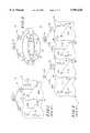
- FIG. 3is a schematic illustration of the wireless communication system of FIG. 1 reconfigured in accordance with a preferred embodiment of the present invention.
- FIG. 4is a schematic illustration of a wireless communication system expanded to double capacity in accordance with a preferred embodiment of the present invention.
- FIG. 5is a schematic illustration of an wireless communication system expanded to double capacity in accordance with an alternate preferred embodiment of the present invention.
- a prior art wireless communication system 10includes a mobile switching center (MSC) 12, a first base station controller (BSC) 14 and a second BSC 16 each servicing service areas 18 and 20 of a total service area 22.
- MSCmobile switching center
- BSCbase station controller
- BSCbase station controller
- BTSbase transceiver stations
- MSC 12, BSCs 14 and 16, and BTSs 24 and 26are specified and operate in accordance with the IS-95-A standard for providing wireless communication services to mobile stations (generally shown as 30) operating in service areas 18 and 20.
- GSMGlobal System for Mobile Communications
- TDMAtime division multiple access
- BSC 16provides service in area 20 using radio frequency channels C1 and C2. Partitioning of system 10 in this manner creates a hard handoff seam 28 between service areas 18 and 20. That is, as mobile station 30 moves from service area 18 to service area 20, a handoff of the mobile station 30 from BTS 24 associated with BSC 14 to BTS 26 associated with BSC 16 may be required.
- FIG. 2an expansion scenario is shown for communication system 10 designated 10'.
- elements from system 10carry the same numeral designation with the addition of a letter "a”.
- Elements added to expand capacitycarry like reference numerals of like elements of system 10 with the addition of a letter "b”.
- the capacity of system 10'is doubled as compared to system 10 through the addition of MSC 12b and BSCs 14b and 16b.
- BTSsare not shown in FIG. 2 for simplicity but are understood to be utilized in each of the service areas, 18a, 20a, 18b and 20b.
- BSCs 14a and 16acontinue to provide service to the respective service areas 18a and 20a.
- BSCs 14b and 16bprovide service in service areas 18b and 20b.
- Each of BSCs 14a, 16a, 14b and 16butilize carriers C1, C2, C3 and C4 for providing service to mobile stations operating in the respective service areas.
- expansion of system 10 to system 10' in this mannerhas created additional hard handoff seams.
- Hard handoff seams 28aremains between BSC 14a and 16a
- new seam 28bis created between BSC 14b and 16b
- new seam 28cis created between BSC 16a/MSC 12a and BSC 14b/MSC 12b.
- the physical size of each service areais reduced leading to increased frequency of hard handoff.
- system 10'offers increased capacity through the addition of two additional carriers and additional equipment but at the penalty of smaller service areas and more hard handoff seams.
- System 100includes BSCs 114 and 116 configured to provide service in each of service areas 118 and 120 on one of carriers C1 and C2, respectively.
- the BSCs 114 and 116are shown to support a single carrier, CX, but it is understood that the illustrated carriers may be a carrier set.
- carrier C1may be a set of carriers including carriers CA, CB, . . . CN.
- Carrier sets C1 and C2must, however, be distinct.
- a carrier setfor example carrier set C2 assigned to BSC 116, may be used by an active BSC, i.e., BSC 114, in the event that a BSC, i.e., BSC 116, fails. This is illustrated in FIG. 3 with the aid of phantom lines.
- each of service area 118 and 120corresponds with the total service area 122 of system 100, and each service area 118 and 120 covers substantially the same physical area as total service area 122.
- BSCs 114 and 116are respectively coupled (utilizing suitable span and backhaul not shown) with base stations 124 and 126 which are now logically shared by both BSCs 114 and 116 for providing service to mobile stations 30 operating in either of service area 118 and 120.
- system 100provides wireless communication service to the entire service area 122 without the hard handoff seam found in system 10.
- BSCs 114 and 116are advantageously coupled to utilize BTSs 124 and 126 and utilize either carrier C1 or C2 or both.
- Typical BTS equipmentsuch as that available from Motorola, Inc, Schaumburg, Ill., have multiple carrier capability.
- a two carrier BTSis logically shared by each of BSCs 114 and 116.
- two single carrier BTSsutilizing a shared antenna and potentially other radio frequency transmission and reception hardware such as power amplifiers, up and down frequency converters and the like, may be coupled respectively to each of BSC 114 and BSC 116.
- multiple BTSsmay be thought to logically share a same physical location and physically share transmission and reception hardware.
- suitable span and backhaul(not shown) is provided and is distinct for each of BSC 114 and 116.
- Mobile station 30acquires access to system 100 in the manner specified in the applicable system standard. However, system 100 is further implemented with appropriate load distribution and shedding logic such that based upon system loading and availability, mobile station 30 is assigned to either of BSC 114 and 116. For example, when mobile station 30 attempts access to the system and there are more mobile stations assigned to BSC 114, mobile station 30 may be assigned to BSC 116. BSC assignment may also be based upon mobile station type, service option, location and/or present or predicted mobility. Moreover, it is contemplated that mobile stations 30 operating in system 100 may be transferred between BSCs 114 and 116 for system balancing. It will be appreciated that numerous suitable mobile station assignment criteria may be implemented without departing from the fair scope of the present invention.
- system 100is shown as system 100' expanded to double capacity. While in the present discussion of preferred embodiments expansion to double capacity is discussed, it will be appreciated that expansion of greater or less amounts may be implemented without departing from the fair scope of the present invention.
- Existing elements in system 100' as shown in FIG. 3are assigned the same reference numeral with the addition of the letter "a”. Like elements to that shown in FIG. 3 but added to expand capacity of system 100 have a like reference numeral with the addition of the letter "b”.
- system 100'includes BSC 114a, BSC 116a, BSC 114b and BSC 116b respectively coupled to MSC 112. Though a single MSC is shown, multiple MSCs may be employed to further expand capacity and enhance system redundancy.
- Each of BSCs 114a, 116a, 114b and 116bare coupled to base stations (not shown in FIG. 4) in total service area 122 for providing communication services in each of service areas 118a, 120a, 118b and 120b.
- each of BSC 114a, 116a, 114b and 116bare assigned one of carriers C1, C2, C3 and C4 in one of service areas 118a, 120a, 118b and 120b.
- Service areas 118a, 120a, 118b and 120beach cover substantially the same physical area, i.e., total service area 122. (the service areas are shown separated in FIG. 4 for clarity).
- the BTSsare multiple carrier BTS equipment, or may be combinations of single and multiple carrier BTS equipment, physically sharing a same antenna and related hardware and logically sharing a same physical location in system 100.
- BSCs 114a, 116a, 114b and 116bmay operate carrier pairs in respectively pairs of service areas 118a, 120b, 118b and 120b.
- suitable load balancing and shedding logicis implemented, either as part of the BTSs and/or the MSs, but may be implemented as part of the BSCs.
- Mobile stations 30attempt access to system 100' in accordance with the applicable standard, and is assigned to one of the carriers, and hence one of the BSCs 114a, 116a, 114b and 116b servicing total area 122.
- System 100'is shown with each of service areas 118a, 120a, 118b and 120b uniformly overlapping each other and covering the entirety of total service area 122.
- the service areasmay be offset.
- Such an arrangementis shown for system 100" in FIG. 5.
- Like reference numeralsare again used to describe like elements with the addition of a prime designation to service areas 118a', 120a', 118b ' and 120b', which are now offset with respect to each other, but share a common portion 132 as shown in FIG. 5. In this manner, expansion may be extended beyond the original total coverage area 122.
- aggregating resources in localized areas, such as common portion 132, where communication traffic density is highmay enhance communication resource utilization or availability.
- the BSCs 114a, 114b, 116a and 116bmay be, and are preferably, located physically remote from each other. In the event of a system failure at one BSC site, the remaining BSCs are available for providing service to total service area 122. Capacity may be reduced due to failure of a piece of equipment, but service area blackouts are eliminated.
- the BTSs for each of the service areasare preferably co-located within a common base station housing and coupled to the antenna located with the base station housing. More preferably, the BTSs are located within a common equipment rack within the base station housing.
- a single communication standard for the service areashas been implied. It will be appreciated that the system may be implemented where a first area is serviced by communication equipment according to a first standard and a second service area is serviced by communication equipment according to a second standard. For example, where a first system is adapted for voice communications and a second system is adapted for data communications. Or, where each of the systems is adapted for voice communications, but according to different communication standards. In each case, higher level communication elements logically share base station equipment, while the base stations physically share certain transmission and reception hardware.
Landscapes
- Engineering & Computer Science (AREA)
- Computer Networks & Wireless Communication (AREA)
- Signal Processing (AREA)
- Mobile Radio Communication Systems (AREA)
Abstract
Description
Claims (21)
Priority Applications (13)
| Application Number | Priority Date | Filing Date | Title |
|---|---|---|---|
| US08/994,587US5991628A (en) | 1997-12-19 | 1997-12-19 | Scalable wireless communication network and method |
| CNB988122138ACN1154370C (en) | 1997-12-19 | 1998-08-21 | Scalable wireless communication network and method |
| JP2000526065AJP4174180B2 (en) | 1997-12-19 | 1998-08-21 | Expandable wireless communication network and method |
| IL13599898AIL135998A (en) | 1997-12-19 | 1998-08-21 | Scalable wireless communication network and method |
| DE19882889TDE19882889B4 (en) | 1997-12-19 | 1998-08-21 | Scalable wireless communication network |
| KR1020007006595AKR20010033203A (en) | 1997-12-19 | 1998-08-21 | Scalable wireless communication network and method |
| BR9815051-0ABR9815051A (en) | 1997-12-19 | 1998-08-21 | Staggered wireless network and method of expanding the capacity of a wireless network |
| CA002315793ACA2315793C (en) | 1997-12-19 | 1998-08-21 | Scalable wireless communication network and method |
| GB0013053AGB2347595B (en) | 1997-12-19 | 1998-08-21 | Scalable wireless communication network and method |
| PCT/US1998/017481WO1999033286A1 (en) | 1997-12-19 | 1998-08-21 | Scalable wireless communication network and method |
| FR9812423AFR2773040B1 (en) | 1997-12-19 | 1998-10-05 | SCALABLE WIRELESS COMMUNICATION NETWORK AND ASSOCIATED METHOD |
| FI20001414AFI118319B (en) | 1997-12-19 | 2000-06-14 | Variable wireless communication network and method |
| SE0002226ASE522655C2 (en) | 1997-12-19 | 2000-06-15 | Scalable, wireless communication network |
Applications Claiming Priority (1)
| Application Number | Priority Date | Filing Date | Title |
|---|---|---|---|
| US08/994,587US5991628A (en) | 1997-12-19 | 1997-12-19 | Scalable wireless communication network and method |
Publications (1)
| Publication Number | Publication Date |
|---|---|
| US5991628Atrue US5991628A (en) | 1999-11-23 |
Family
ID=25540827
Family Applications (1)
| Application Number | Title | Priority Date | Filing Date |
|---|---|---|---|
| US08/994,587Expired - LifetimeUS5991628A (en) | 1997-12-19 | 1997-12-19 | Scalable wireless communication network and method |
Country Status (13)
| Country | Link |
|---|---|
| US (1) | US5991628A (en) |
| JP (1) | JP4174180B2 (en) |
| KR (1) | KR20010033203A (en) |
| CN (1) | CN1154370C (en) |
| BR (1) | BR9815051A (en) |
| CA (1) | CA2315793C (en) |
| DE (1) | DE19882889B4 (en) |
| FI (1) | FI118319B (en) |
| FR (1) | FR2773040B1 (en) |
| GB (1) | GB2347595B (en) |
| IL (1) | IL135998A (en) |
| SE (1) | SE522655C2 (en) |
| WO (1) | WO1999033286A1 (en) |
Cited By (19)
| Publication number | Priority date | Publication date | Assignee | Title |
|---|---|---|---|---|
| WO2000025532A1 (en)* | 1998-10-28 | 2000-05-04 | Motorola Inc. | Method and apparatus for backhauling data in a communication system |
| US6091953A (en)* | 1997-08-06 | 2000-07-18 | Nortel Networks Limited | Distributed signaling message routing in a scalable wireless communication system |
| US6097951A (en)* | 1997-08-06 | 2000-08-01 | Northern Telecom Limited | Method and apparatus for wireless network architecture based on subscriber distribution |
| US6122513A (en)* | 1997-11-06 | 2000-09-19 | Nortel Networks Corporation | Method for extending hard-handoff boundaries within a mobile telephone communications network |
| US6141559A (en)* | 1998-11-04 | 2000-10-31 | Motorola, Inc. | Method and apparatus for performing selection and distribution in a communication system |
| US6243367B1 (en)* | 1997-12-31 | 2001-06-05 | Samsung Electronics Co., Ltd. | Systems and methods for providing a client-server architecture for CDMA base stations |
| US6263187B1 (en)* | 1999-01-08 | 2001-07-17 | Lucent Technologies Inc. | Obtaining data for calls made by a specific/cellular mobile station |
| US20020001293A1 (en)* | 2000-05-17 | 2002-01-03 | Jong-Ho Kim | CDMA 3X base transceiver station in mobile communication system |
| US6385449B2 (en)* | 1998-03-06 | 2002-05-07 | Telefonaktiebolaget L M Ericsson | System and method used in a mobile telecommunications network for load balancing ongoing calls between different base station controllers |
| US20020193105A1 (en)* | 2001-06-13 | 2002-12-19 | Olsson John Gunnar | Dynamic Handling of orphan cells |
| US20030032454A1 (en)* | 2001-08-13 | 2003-02-13 | Andrew Corporation | Architecture for digital shared antenna system to support existing base station hardware |
| US20030076803A1 (en)* | 2001-08-22 | 2003-04-24 | Chuah Mooi Choo | Reconfigurable wireless communication access system and method |
| US20030125036A1 (en)* | 2001-12-27 | 2003-07-03 | Nec Corporation | CDMA cellular system in which different channel is allocated |
| US20040076135A1 (en)* | 2000-12-12 | 2004-04-22 | Lars-Berno Fredriksson | Company network using time slot reuse |
| US6909879B1 (en)* | 2000-08-22 | 2005-06-21 | Cellco Partnership | Methods and apparatus for utilizing radio frequency spectrum simultaneously and concurrently in the presence of co-channel and/or adjacent channel television signals |
| EP1111821A3 (en)* | 1999-12-21 | 2005-08-17 | Lucent Technologies Inc. | Wireless system combining arrangment and method thereof |
| US20060084436A1 (en)* | 2004-06-29 | 2006-04-20 | Michael Green | Methods and apparatus for inter-BSC soft handoff |
| US20070149199A1 (en)* | 1999-09-30 | 2007-06-28 | Atsushi Kanagawa | Mobile communications system |
| US9106286B2 (en) | 2000-06-13 | 2015-08-11 | Comcast Cable Communications, Llc | Network communication using diversity |
Families Citing this family (3)
| Publication number | Priority date | Publication date | Assignee | Title |
|---|---|---|---|---|
| TWI320666B (en) | 2002-04-12 | 2010-02-11 | Interdigital Tech Corp | An access burst detector for use in a node b/base station |
| US20080123610A1 (en)* | 2006-11-29 | 2008-05-29 | Prasanna Desai | Method and system for a shared antenna control using the output of a voice activity detector |
| SG173913A1 (en)* | 2009-03-03 | 2011-10-28 | Agency Science Tech & Res | A method of communication |
Citations (5)
| Publication number | Priority date | Publication date | Assignee | Title |
|---|---|---|---|---|
| US4775998A (en)* | 1987-07-20 | 1988-10-04 | Motorola, Inc. | Cellular radiotelephone system having colocated base sites |
| US5093925A (en)* | 1990-04-25 | 1992-03-03 | Motorola, Inc. | Three dimensional cellular communication system with coordinate offset and frequency reuse |
| US5208847A (en)* | 1991-02-25 | 1993-05-04 | Northern Telecom Limited | Method of increasing capacity of cellular network |
| US5697055A (en)* | 1994-10-16 | 1997-12-09 | Qualcomm Incorporated | Method and apparatus for handoff between different cellular communications systems |
| US5790528A (en)* | 1994-01-27 | 1998-08-04 | Nokia Telecommunications Oy | Semi-hard handoff in a cellular telecommunications systems |
Family Cites Families (4)
| Publication number | Priority date | Publication date | Assignee | Title |
|---|---|---|---|---|
| FI88660C (en)* | 1991-01-09 | 1993-06-10 | Nokia Telecommunications Oy | Radiosändarmottagarsystem |
| US5592480A (en)* | 1995-03-13 | 1997-01-07 | Carney; Ronald R. | Wideband wireless basestation making use of time division multiple-access bus having selectable number of time slots and frame synchronization to support different modulation standards |
| US5781865A (en)* | 1996-05-20 | 1998-07-14 | Scientific Research Corporation | PCS cell site system for allowing a plurality of PCS providers to share cell site antennas |
| GB2320653A (en)* | 1996-12-23 | 1998-06-24 | Northern Telecom Ltd | Mobile Communications Network Using Alternative Protocols |
- 1997
- 1997-12-19USUS08/994,587patent/US5991628A/ennot_activeExpired - Lifetime
- 1998
- 1998-08-21JPJP2000526065Apatent/JP4174180B2/ennot_activeExpired - Lifetime
- 1998-08-21CACA002315793Apatent/CA2315793C/ennot_activeExpired - Lifetime
- 1998-08-21ILIL13599898Apatent/IL135998A/ennot_activeIP Right Cessation
- 1998-08-21BRBR9815051-0Apatent/BR9815051A/ennot_activeApplication Discontinuation
- 1998-08-21WOPCT/US1998/017481patent/WO1999033286A1/ennot_activeApplication Discontinuation
- 1998-08-21KRKR1020007006595Apatent/KR20010033203A/ennot_activeCeased
- 1998-08-21GBGB0013053Apatent/GB2347595B/ennot_activeExpired - Lifetime
- 1998-08-21DEDE19882889Tpatent/DE19882889B4/ennot_activeExpired - Lifetime
- 1998-08-21CNCNB988122138Apatent/CN1154370C/ennot_activeExpired - Lifetime
- 1998-10-05FRFR9812423Apatent/FR2773040B1/ennot_activeExpired - Lifetime
- 2000
- 2000-06-14FIFI20001414Apatent/FI118319B/ennot_activeIP Right Cessation
- 2000-06-15SESE0002226Apatent/SE522655C2/ennot_activeIP Right Cessation
Patent Citations (5)
| Publication number | Priority date | Publication date | Assignee | Title |
|---|---|---|---|---|
| US4775998A (en)* | 1987-07-20 | 1988-10-04 | Motorola, Inc. | Cellular radiotelephone system having colocated base sites |
| US5093925A (en)* | 1990-04-25 | 1992-03-03 | Motorola, Inc. | Three dimensional cellular communication system with coordinate offset and frequency reuse |
| US5208847A (en)* | 1991-02-25 | 1993-05-04 | Northern Telecom Limited | Method of increasing capacity of cellular network |
| US5790528A (en)* | 1994-01-27 | 1998-08-04 | Nokia Telecommunications Oy | Semi-hard handoff in a cellular telecommunications systems |
| US5697055A (en)* | 1994-10-16 | 1997-12-09 | Qualcomm Incorporated | Method and apparatus for handoff between different cellular communications systems |
Cited By (46)
| Publication number | Priority date | Publication date | Assignee | Title |
|---|---|---|---|---|
| US6091953A (en)* | 1997-08-06 | 2000-07-18 | Nortel Networks Limited | Distributed signaling message routing in a scalable wireless communication system |
| US6097951A (en)* | 1997-08-06 | 2000-08-01 | Northern Telecom Limited | Method and apparatus for wireless network architecture based on subscriber distribution |
| US6553227B1 (en)* | 1997-08-06 | 2003-04-22 | Nortel Networks Ltd | Distributed signaling message routing in a scalable wireless communication system |
| US6148201A (en)* | 1997-08-06 | 2000-11-14 | Nortel Networks Corporation | Scalable wireless network architecture based on subscriber distribution |
| US6122513A (en)* | 1997-11-06 | 2000-09-19 | Nortel Networks Corporation | Method for extending hard-handoff boundaries within a mobile telephone communications network |
| US6243367B1 (en)* | 1997-12-31 | 2001-06-05 | Samsung Electronics Co., Ltd. | Systems and methods for providing a client-server architecture for CDMA base stations |
| US6385449B2 (en)* | 1998-03-06 | 2002-05-07 | Telefonaktiebolaget L M Ericsson | System and method used in a mobile telecommunications network for load balancing ongoing calls between different base station controllers |
| US6353742B1 (en)* | 1998-10-28 | 2002-03-05 | Motorola, Inc. | Method and apparatus for backhauling data in a communication system |
| WO2000025532A1 (en)* | 1998-10-28 | 2000-05-04 | Motorola Inc. | Method and apparatus for backhauling data in a communication system |
| US6141559A (en)* | 1998-11-04 | 2000-10-31 | Motorola, Inc. | Method and apparatus for performing selection and distribution in a communication system |
| US6341222B1 (en)* | 1998-11-04 | 2002-01-22 | Motorola, Inc. | Method and apparatus for performing selection and distribution in a communication system |
| US6263187B1 (en)* | 1999-01-08 | 2001-07-17 | Lucent Technologies Inc. | Obtaining data for calls made by a specific/cellular mobile station |
| US20070149199A1 (en)* | 1999-09-30 | 2007-06-28 | Atsushi Kanagawa | Mobile communications system |
| EP1111821A3 (en)* | 1999-12-21 | 2005-08-17 | Lucent Technologies Inc. | Wireless system combining arrangment and method thereof |
| KR100711015B1 (en)* | 1999-12-21 | 2007-04-25 | 루센트 테크놀러지스 인크 | Wireless system combining arrangement and method thereof |
| US20020001293A1 (en)* | 2000-05-17 | 2002-01-03 | Jong-Ho Kim | CDMA 3X base transceiver station in mobile communication system |
| US7280509B2 (en) | 2000-05-17 | 2007-10-09 | Utstarcom, Inc. | CDMA 3X base transceiver station in mobile communication system |
| USRE45807E1 (en) | 2000-06-13 | 2015-11-17 | Comcast Cable Communications, Llc | Apparatus for transmitting a signal including transmit data to a multiple-input capable node |
| US9401783B1 (en) | 2000-06-13 | 2016-07-26 | Comcast Cable Communications, Llc | Transmission of data to multiple nodes |
| US10349332B2 (en) | 2000-06-13 | 2019-07-09 | Comcast Cable Communications, Llc | Network communication using selected resources |
| US10257765B2 (en) | 2000-06-13 | 2019-04-09 | Comcast Cable Communications, Llc | Transmission of OFDM symbols |
| US9820209B1 (en) | 2000-06-13 | 2017-11-14 | Comcast Cable Communications, Llc | Data routing for OFDM transmissions |
| US9722842B2 (en) | 2000-06-13 | 2017-08-01 | Comcast Cable Communications, Llc | Transmission of data using a plurality of radio frequency channels |
| US9654323B2 (en) | 2000-06-13 | 2017-05-16 | Comcast Cable Communications, Llc | Data routing for OFDM transmission based on observed node capacities |
| US9515788B2 (en) | 2000-06-13 | 2016-12-06 | Comcast Cable Communications, Llc | Originator and recipient based transmissions in wireless communications |
| US9391745B2 (en) | 2000-06-13 | 2016-07-12 | Comcast Cable Communications, Llc | Multi-user transmissions |
| US9356666B1 (en) | 2000-06-13 | 2016-05-31 | Comcast Cable Communications, Llc | Originator and recipient based transmissions in wireless communications |
| US9344233B2 (en) | 2000-06-13 | 2016-05-17 | Comcast Cable Communications, Llc | Originator and recipient based transmissions in wireless communications |
| US9209871B2 (en) | 2000-06-13 | 2015-12-08 | Comcast Cable Communications, Llc | Network communication using diversity |
| US9197297B2 (en) | 2000-06-13 | 2015-11-24 | Comcast Cable Communications, Llc | Network communication using diversity |
| USRE45775E1 (en) | 2000-06-13 | 2015-10-20 | Comcast Cable Communications, Llc | Method and system for robust, secure, and high-efficiency voice and packet transmission over ad-hoc, mesh, and MIMO communication networks |
| US9106286B2 (en) | 2000-06-13 | 2015-08-11 | Comcast Cable Communications, Llc | Network communication using diversity |
| US6909879B1 (en)* | 2000-08-22 | 2005-06-21 | Cellco Partnership | Methods and apparatus for utilizing radio frequency spectrum simultaneously and concurrently in the presence of co-channel and/or adjacent channel television signals |
| US20040076135A1 (en)* | 2000-12-12 | 2004-04-22 | Lars-Berno Fredriksson | Company network using time slot reuse |
| US7844679B2 (en)* | 2000-12-12 | 2010-11-30 | Lars-Berno Fredriksson | Company network using time slot reuse |
| US20020193105A1 (en)* | 2001-06-13 | 2002-12-19 | Olsson John Gunnar | Dynamic Handling of orphan cells |
| US20030032454A1 (en)* | 2001-08-13 | 2003-02-13 | Andrew Corporation | Architecture for digital shared antenna system to support existing base station hardware |
| US7003322B2 (en) | 2001-08-13 | 2006-02-21 | Andrew Corporation | Architecture for digital shared antenna system to support existing base station hardware |
| US7043270B2 (en) | 2001-08-13 | 2006-05-09 | Andrew Corporation | Shared tower system for accomodating multiple service providers |
| US7346023B2 (en)* | 2001-08-22 | 2008-03-18 | Lucent Technologies Inc. | Reconfigurable wireless communication access system and method |
| US20030076803A1 (en)* | 2001-08-22 | 2003-04-24 | Chuah Mooi Choo | Reconfigurable wireless communication access system and method |
| US7069012B2 (en) | 2001-12-27 | 2006-06-27 | Nec Corporation | CDMA cellular system in which different channel is allocated |
| US20030125036A1 (en)* | 2001-12-27 | 2003-07-03 | Nec Corporation | CDMA cellular system in which different channel is allocated |
| EP1326461A3 (en)* | 2001-12-27 | 2004-02-04 | Nec Corporation | CDMA cellular system in which different channel is allocated |
| US20060084436A1 (en)* | 2004-06-29 | 2006-04-20 | Michael Green | Methods and apparatus for inter-BSC soft handoff |
| US7359709B2 (en)* | 2004-06-29 | 2008-04-15 | Qualcomm, Incorporated | Methods and apparatus for inter-BSC soft handoff |
Also Published As
| Publication number | Publication date |
|---|---|
| JP2001527355A (en) | 2001-12-25 |
| DE19882889B4 (en) | 2010-10-07 |
| JP4174180B2 (en) | 2008-10-29 |
| KR20010033203A (en) | 2001-04-25 |
| SE0002226D0 (en) | 2000-06-15 |
| FI118319B (en) | 2007-09-28 |
| GB0013053D0 (en) | 2000-07-19 |
| BR9815051A (en) | 2000-10-03 |
| SE0002226L (en) | 2000-08-16 |
| WO1999033286A1 (en) | 1999-07-01 |
| GB2347595B (en) | 2002-12-18 |
| CA2315793A1 (en) | 1999-07-01 |
| CN1282491A (en) | 2001-01-31 |
| GB2347595A (en) | 2000-09-06 |
| FI20001414L (en) | 2000-06-14 |
| SE522655C2 (en) | 2004-02-24 |
| FR2773040B1 (en) | 2000-10-13 |
| IL135998A (en) | 2004-07-25 |
| FR2773040A1 (en) | 1999-06-25 |
| CN1154370C (en) | 2004-06-16 |
| IL135998A0 (en) | 2001-05-20 |
| CA2315793C (en) | 2003-06-03 |
| DE19882889T1 (en) | 2001-04-12 |
Similar Documents
| Publication | Publication Date | Title |
|---|---|---|
| US5991628A (en) | Scalable wireless communication network and method | |
| KR100276810B1 (en) | Client-Server Architecture Implementation Method and Method for CDA Base Station | |
| US8077640B2 (en) | Method for supporting asymmetric service flexible in multi-carrier time division duplex mobile communication system | |
| Lee | Smaller cells for greater performance | |
| KR100259846B1 (en) | Semi-soft handoff using multiple common frequencies | |
| AU703574B2 (en) | Distributed radio telecommunications system | |
| US5774790A (en) | Sectorized cellular mobile radio system with sector signalling and control in predetermined time slots | |
| EP0652644B1 (en) | Base station transmission-reception apparatus for cellular system | |
| US6898431B1 (en) | Dynamic channel allocation in a sectored cell of a cellular communication system | |
| WO2008061701A1 (en) | Method and system for wireless cellular indoor communications | |
| US5845199A (en) | Simulcasting system with diversity reception | |
| US11777554B2 (en) | In-device coexistence for new radio | |
| US20210314786A1 (en) | Method of microcell management in mobile communications system using centralized basestation | |
| CN1337841A (en) | Frequency distribution system and method for realizing same used in wireless communication system | |
| US7474895B1 (en) | Frequency reuse in wireless communication networks | |
| EP1232661B1 (en) | Communications system load control methods and apparatus | |
| JP2002521988A (en) | Apparatus, method and system for improving communication network capacity | |
| US7912479B2 (en) | Radio-channel connection controller and mobile communication network system | |
| US6212387B1 (en) | Method and apparatus for collector arrays of directional antennas co-located with zone managers in wireless communications systems | |
| US20080318589A1 (en) | Transmission Optimization in a Wireless Base Station System Based on Load-Sharing | |
| US7142828B2 (en) | Base station for a telecommunication system | |
| EP1106023B1 (en) | Layered wireless communication system and method | |
| KR20000045001A (en) | Dynamic control method and unit of cell grouping in mobile telecommunication system | |
| JP2002369244A (en) | Small-capacity base station control system for cdma mobile communication system, and method therefor | |
| KR19990039670A (en) | How to eliminate hard handoff between frequencies in digital code division multiple access mobile communication systems |
Legal Events
| Date | Code | Title | Description |
|---|---|---|---|
| AS | Assignment | Owner name:MOTOROLA, INC., ILLINOIS Free format text:ASSIGNMENT OF ASSIGNORS INTEREST;ASSIGNORS:PEDZIWIATR, JOSEPH M.;STEINBERG, PAUL D.;MACKENZIE, ARMIDA R.;REEL/FRAME:008914/0722;SIGNING DATES FROM 19971218 TO 19971219 | |
| STCF | Information on status: patent grant | Free format text:PATENTED CASE | |
| FPAY | Fee payment | Year of fee payment:4 | |
| REMI | Maintenance fee reminder mailed | ||
| FPAY | Fee payment | Year of fee payment:8 | |
| AS | Assignment | Owner name:MOTOROLA MOBILITY, INC, ILLINOIS Free format text:ASSIGNMENT OF ASSIGNORS INTEREST;ASSIGNOR:MOTOROLA, INC;REEL/FRAME:025673/0558 Effective date:20100731 | |
| FPAY | Fee payment | Year of fee payment:12 | |
| AS | Assignment | Owner name:MOTOROLA MOBILITY LLC, ILLINOIS Free format text:CHANGE OF NAME;ASSIGNOR:MOTOROLA MOBILITY, INC.;REEL/FRAME:029216/0282 Effective date:20120622 | |
| AS | Assignment | Owner name:GOOGLE TECHNOLOGY HOLDINGS LLC, CALIFORNIA Free format text:ASSIGNMENT OF ASSIGNORS INTEREST;ASSIGNOR:MOTOROLA MOBILITY LLC;REEL/FRAME:034500/0001 Effective date:20141028 |