US5991303A - Multi-rate switching physical device for a mixed communication rate ethernet repeater - Google Patents
Multi-rate switching physical device for a mixed communication rate ethernet repeaterDownload PDFInfo
- Publication number
- US5991303A US5991303AUS08/901,112US90111297AUS5991303AUS 5991303 AUS5991303 AUS 5991303AUS 90111297 AUS90111297 AUS 90111297AUS 5991303 AUS5991303 AUS 5991303A
- Authority
- US
- United States
- Prior art keywords
- physical device
- circuit
- device circuit
- coupled
- communication rate
- Prior art date
- Legal status (The legal status is an assumption and is not a legal conclusion. Google has not performed a legal analysis and makes no representation as to the accuracy of the status listed.)
- Expired - Fee Related
Links
- 238000004891communicationMethods0.000titleclaimsabstractdescription70
- 239000000835fiberSubstances0.000claimsabstractdescription8
- 239000004065semiconductorSubstances0.000claimsdescription4
- 239000000758substrateSubstances0.000claimsdescription4
- 230000011664signalingEffects0.000claimsdescription2
- 238000010586diagramMethods0.000description10
- 238000013461designMethods0.000description9
- 230000008878couplingEffects0.000description4
- 238000010168coupling processMethods0.000description4
- 238000005859coupling reactionMethods0.000description4
- 230000009977dual effectEffects0.000description4
- 238000000034methodMethods0.000description4
- 230000006855networkingEffects0.000description4
- 230000008867communication pathwayEffects0.000description3
- 238000001514detection methodMethods0.000description3
- 230000037361pathwayEffects0.000description3
- 230000005465channelingEffects0.000description2
- 239000000203mixtureSubstances0.000description2
- 238000011084recoveryMethods0.000description2
- 238000006243chemical reactionMethods0.000description1
- 238000012937correctionMethods0.000description1
- 238000011161developmentMethods0.000description1
- 230000000694effectsEffects0.000description1
- 238000001914filtrationMethods0.000description1
- 230000007246mechanismEffects0.000description1
- 238000012544monitoring processMethods0.000description1
- 238000007493shaping processMethods0.000description1
Images


Classifications
- H—ELECTRICITY
- H04—ELECTRIC COMMUNICATION TECHNIQUE
- H04L—TRANSMISSION OF DIGITAL INFORMATION, e.g. TELEGRAPHIC COMMUNICATION
- H04L49/00—Packet switching elements
- H04L49/35—Switches specially adapted for specific applications
- H04L49/351—Switches specially adapted for specific applications for local area network [LAN], e.g. Ethernet switches
Definitions
- the present inventionrelates to the field of local area networks (LANs) using the Ethernet communication protocol (e.g., the IEEE 802.3 Standard). Specifically, the present invention relates to a switchable physical device component within a network repeater hub.
- LANslocal area networks
- Ethernet communication protocole.g., the IEEE 802.3 Standard
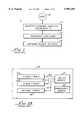
- FIG. 1illustrates a high level block diagram of the communication levels within a typical communication network system 5.
- System 5has a first communication level 12 including communication adapters ("cards") that are inserted into computer systems to provide them with networking capability.
- the computer systemsinterface with users 10.
- the second communication level 14is the workgroup level and includes hubs (e.g., repeater hubs, switching hubs, etc.).
- the hubsprovide communication pathways between computer systems of the same or multiple local area networks (LANs).
- LANslocal area networks
- Computer systems coupled to a common hubshare the same collision domain.
- a collision domainis a group of computer systems logically connected to share the same physical bandwidth (e.g. 10 Megabits/sec or 100 Megabits/sec) of a communication pathway.
- a collision domainis managed by a repeater interface controller (RIC).
- the third level 16is often called the backbone or backplane level and can include segment switches. Among other functions, the components of level 16 provide communication pathways between hubs and between different collision domains.
- FIG. 2Aillustrates a prior art communication system 44 employing two repeater hubs 30 and 32.
- Repeater hubsare low cost because they do not require an expensive media access controller (MAC) for each port nor do they require switches; only a physical device (e.g., 21a-21d or 23a-23d) is required at each port to provide repeating.
- MACmedia access controller
- all ports of a repeater hub(the hub having one repeater interface controller, RIC) are required to be of the same communication rate because: (1) messages from one port are repeated to all other ports by the hub's RIC; and (2) because only one RIC is provided, only one collision domain is allowed.
- 10/100 adapters 20a-20dare coupled to repeater hub 30 operating at 10 M while 10/100 adapters 22a-22d are coupled to repeater hub 32 operating at 100 M.
- the adapters 20a-20d and 22a-22dare coupled to their associated hubs through physical devices 21a-21d and 23a-23d, respectively.
- the repeater hubs 30 and 32are coupled to backbone circuit 40 through pathways 34 and 36, respectively.
- Backbone circuit 40may contain segment switches or routers. Due to the difference in operational speeds of hubs 30 and 32, the only means by which the two hubs can communicate is through backbone level 40, which has circuits that can adapt the data from each segment.
- FIG. 2Billustrates a similar prior art communication system 78 using three exemplary stackable low cost repeater hubs 50a, 50b and 54 that each use a single RIC.
- Hubs 50a and 50boperate at 10 M while hub 54 operates at 100 M.
- Hubs 50a and 50bare coupled to switch module 62 via separate pathways 52a and 52b, respectively, while hub 54 is coupled to switch circuit 62 via separate pathway 56.
- the switch module 62provides communication between the different collision domain segments. This can be accomplished either using a bus based CPU architecture or a cross bar switch architecture.
- a management module 64is also included and interfaces with the switch module 62.
- the majority of installed repeater hubssupport only 10 M communication (e.g., 10 Base T). If one port of a 10 M repeater hub (e.g., hub 30 or a hub of hubs 50a and 50b) needs to be upgraded to 100 M, all ports within the 10 M repeater hub need to be upgraded because the hub only supports one collision domain. This causes a problem because the cost of performing such an upgrade for all ports in a 10 M repeater hub is very expensive and can be impractical if only one port needs the 100 M communication rate.
- the prior art solution for providing 100 M communicationhas been to add repeaters, e.g., repeater hub 54, that handle only 100 M communication.
- FIG. 3illustrates a high cost communication network 96 based on a switching hub 90 that provides mixed 10 M and 100 M ports.
- Adapters 80a-80h of the 10/100 typeare coupled via respective physical devices 81a-81h to switching hub 90.
- Switching hub 90contains complex circuitry 92 to provide multiple independent communication channels between respective pairs of adapters 80a-80h. Switching hub 90 allows for mixed 10 M and 100 M ports because independent communication channels can be formed between adapter pairs.
- system 96is a very expensive network solution due to the required switching logic. For instance, the cost per port of the switching hub 90 is well over an order of magnitude greater than the cost per port of repeater system 44 (FIG. 2A) or repeater system 78 (FIG. 2B).
- switching hub 90is not a practical solution for providing mixed 10 M and 100 M ports within a workgroup hub because of its high cost per port. It would be advantageous to provide a workgroup hub that offers the flexibility of mixed 10 M and 100 M ports while avoiding the high cost per port associated with switching hubs.
- the present inventionprovides such a repeater hub.
- repeater hubsincorporate more than one RIC circuit allowing a mixture of both 10 M and 100 M ports within a single 10/100 repeater hub.
- the physical device circuits 100 of the prior artwhile supporting either 10 Base T 106 or 100 Base T 108 communication, nevertheless offer only one media independent interface (MII) 104. Therefore, each port within the prior art 10/100 repeater hub (using physical device 100) is hardwired to communicate within one, and only one, collision domain 102 (e.g., 100 M domain or 10 M domain).
- MIImedia independent interface
- this prior art 10/100 repeater hubis not flexible with respect to changes in the computer system coupled to a particular port. For instance, if a particular port is operating at 100 M and the user for that port is replaced with another user that does not need 100 M, a significant amount of reconfiguration is required (e.g., by a system administrator or communication technician) to rewire the particular port into another collision domain or wire another user into the particular port. Alternatively, if the particular port is not rewired, then resource bandwidth becomes wasted as 100 M is being reserved for a possible 10 M use. It would be advantageous to provide a low cost 10/100 repeater hub that provides port-by-port flexible reconfiguration between multiple collision domains without requiring expensive switching circuitry. The present invention provides such a repeater hub.
- the present inventionprovides a low cost repeater hub that offers the flexibility of readily upgrading one or more ports of the hub to 100 M while allowing the remainder ports to operate at 10 M.
- the present inventionprovides workgroup repeater hub that offers the flexibility of mixed 10 M and 100 M ports while avoiding the high cost per port associated with switching hubs.
- the present inventionprovides a low cost 10/100 repeater hub with port-by-port flexible reconfiguration between multiple collision domains without external switching circuitry applied to the physical device.
- the present inventionprovides such a repeater hub with a novel switching physical device.
- a multi-communication rate switching physical deviceis described herein for a port of a mixed communication rate Ethernet repeater network.
- the present inventionprovides a low cost solution allowing an installed based of 10/100 adapters to advantageously communicate at 100 M.
- the present inventionincludes a physical device for recovering bits from a wire connection (e.g., fiber, twisted pair, etc.) that is coupled to an adapter of a computer system.
- the physical devicecan be implemented on a single chip integrated within an Ethernet repeater hub within each hub port.
- the physical device chip of the inventionincludes a front end multiplexer coupled to channel information between a 10 Base T physical device circuit and a 100 Base T physical device circuit, depending on the result of an auto-negotiation circuit also on the physical device chip.
- the physical device chipalso advantageously employs a second, back end multiplexer, that is coupled to channel data between (1) either the 10 Base T physical device circuit or the 100 Base T physical device circuit and (2) one of a multiple of media independent interfaces (MIIs).
- MIIsmedia independent interfaces
- the back end multiplexeris controlled by a combination of signals including the result of the auto-negotiation circuit and a system management interface override signal.
- the inventionprovides a low cost solution allowing the associated port to be automatically associated with one of a number of different collision domains within the Ethernet network. Therefore, separate ports within a same repeater hub (or configuration of stackable repeater hubs) can be assigned to different collision domains without requiring expensive switching equipment.
- the present inventionprovides an Ethernet 10/100 repeater hub allowing ports of one group of the 10/100 repeater hub to be assigned to a 100 Base T domain and ports of another group of the 10/100 repeater hub to be assigned to a 10 Base T domain.
- Port assignment to one domain or anotheris flexible and can be based on: (1) the result of an auto-negotiation session; (2) a manual override; or (3) detected errors in the fastest attempted rate.
- the present inventionis a low cost solution allowing the installed based of 10/100 adapters to advantageously communicate at 100 M.
- embodiments of the present inventioninclude a switchable physical device circuit integrated on a semiconductor substrate for interfacing with an adapter of a computer system, the switchable physical device circuit comprising: a first physical device circuit (e.g., Ethernet 10 Base T) operable at a first communication rate; a second physical device circuit (e.g., Ethernet 100 Base T) operable at a second communication rate; an auto-negotiation circuit for determining if the adapter is able to communicate at the second communication rate and generating a result signal indicative thereof; a front end multiplexer controlled by the result signal and for multiplexing information between the adapter and one of the first and the second physical device circuits; a first media independent interface circuit for communicating with a first collision domain; a second media independent interface circuit for communicating with a second collision domain; and a back end multiplexer controlled by the result signal and for multiplexing information between one of the first and the second physical device circuits and one of the first and the second media independent interface circuits.
- a switchable physical device circuitintegrated on
- FIG. 1is a prior art diagram of three levels of an Ethernet communication network including one level at the adapter of a computer system, a second workgroup level including repeater hubs and a third backbone level including segment switches.
- FIG. 2Ais a prior art network design having multiple repeater hubs coupled to a backbone circuit.
- FIG. 2Bis a prior art network similar to FIG. 2A but implemented with multi-port stackable repeater hubs.
- FIG. 3is a prior art network design employing an expensive switch circuit to provide separate communication paths between coupled computer systems.
- FIG. 4is a prior art physical device circuit employing only one media independent interface (MII) connection for its associated port.
- MIImedia independent interface
- FIG. 5is a switching physical device in accordance with the present invention including a controlled back end multiplexer for channeling information to one of multiple MII interface connections (e.g., two).
- a controlled back end multiplexerfor channeling information to one of multiple MII interface connections (e.g., two).
- FIG. 6Ais a block diagram of the 10 Base T communication circuitry of the physical device of the present invention.
- FIG. 6Bis a block diagram of the 100 Base T communication circuitry of the physical device of the present invention.
- FIG. 7is a switching physical device in accordance with the present invention including a controlled back end multiplexer for channeling information to one of multiple MII interface connections (e.g., four) within a 10/100 repeater hub.
- a controlled back end multiplexerfor channeling information to one of multiple MII interface connections (e.g., four) within a 10/100 repeater hub.
- FIG. 8Ais a block diagram of a quad physical device (quad-phy) for four ports and having four domains and implemented on a single chip.
- FIG. 8Bis a block diagram of a quad physical device (quad-phy) for four ports and having two domains and implemented on a single chip.
- FIG. 9Ais a block diagram illustrating a particular embodiment of the present invention for controlling the back end multiplexer of the present invention including one control line from the auto-negotiation circuit and a manual override signal originating from a system management interface.
- FIG. 9Bis a diagram of one exemplary control register for controlling the manual overrides for a single port in accordance with the present invention.
- FIG. 10is a block diagram of a 10/100 repeater hub implemented in accordance with the present invention and coupled to a number of networked computer systems.
- FIG. 11illustrates an exemplary local area network of stackable 10/100 repeater hubs and also illustrates the flexible port assignments allowed by the repeater hubs of the present invention between four exemplary collision domains.
- the physical device 200is associated with each port of a repeater hub and is coupled to an adapter card 280 of an associated computer system (e.g., of the X86, Apple Macintosh, Sun, etc. design) via a twisted pair wire or fiber connection 284.
- the physical device 200is used to recover bits of the signal information transmitted on connection 284. Once recovered by the physical device 200, the information can be repeated and forwarded to another port of a repeater hub or can be forwarded to higher level circuitry (e.g., a media access controller, MAC) that can construct a packet of information based on the recovered bits.
- MACmedia access controller
- Physical device 200is preferably implemented on a single semiconductor substrate (e.g., a "chip") and includes, at the front side, a line driver/receiver circuit 250 coupled to connection 284 (e.g., twisted pair wire).
- the line driver/receiver circuit 250is coupled to communicate information with a front end multiplexer circuit 240.
- the select input of the front end multiplexer circuit 240is controlled by a control signal in bus 262 generated by an auto-negotiation circuit 260.
- Auto-negotiation circuit 260is coupled by bus 292 to the line driver/receiver circuit 250.
- the auto-negotiation circuit 260is implemented in accordance with the IEEE 802.3 standard and a number of well known designs can be used.
- the front end multiplexer circuit 240is coupled via bus 244 to a 10 Base T physical device circuit 220 and coupled via bus 242 to a 100 Base T physical device circuit 230. Front end multiplexer circuit 240 under control from the auto-negotiation circuit 260 multiplexes signals from bus 252 to either bus 244 or bus 242. Physical device 200 supports both 10 Base T and 100 Base T communication protocols.
- physical device 200 of FIG. 5includes a back end multiplexer 218 coupled by bus 222 to the 10 Base T physical device circuit 220 and coupled by bus 232 to the 100 Base T physical device circuit 230.
- well known circuitscan be utilized for 10 Base T physical device circuit 220 and 100 Base T physical device circuit 230 which are described in more detail in FIG. 6A and FIG. 6B.
- the 100 Base T physical devicecan be implemented to support any of the IEEE 100 Base T standards, including 100 Base T2 and 100 Base TX for example. It is appreciated that physical device 200 can include more than two device circuits 220 and 230.
- a third physical device circuitcan be used within physical device 200 that supports different types of either 10 Base T or 100 Base T communication, or, that supports 1000 Base T communication, etc.
- Physical device 200advantageously includes more than one media independent interface (MII) allowing physical device 200 to be readily multiplexed between more than one collision domain.
- MIImedia independent interface
- physical device 200includes a first MII interface circuit (MII one) 214 and a second MII interface circuit (MII two) 216.
- MII one circuit 214is coupled to back end multiplexer 218 by bus 214a and MII two circuit 216 is coupled to back end multiplexer 218 by bus 216a.
- MII one circuit 214is for communicating with a first collision domain (domain 1) 210 and MII two circuit 216 is for communicating with a second collision domain (domain 2) 212.
- domain 1 210is established by a 10 M repeater interface controller (RIC) and domain 2 212 is established by a 100 M RIC.
- the RIC 10 M and the RIC 100 Mcan be integrated into a single 10/100 repeater of the present invention (see FIG. 10 for instance).
- the select input of the back end multiplexer 218is controlled by the control bus 264 that receives part of its signal from the result of the auto-negotiation circuit (e.g., the signal over bus 262) and part of its signal from a management interface circuit 270.
- the management interface circuit 270provides a system management interface (SMI) including configuration override signals and receives control information from an SMI interface 290. Except as described differently herein, the management interface circuit 270 can be implemented using a number of well known designs.
- a first control signalis generated by auto-negotiation circuit 260 to front end multiplexer 240 and to back end multiplexer 218 causing bus 252 to be coupled to bus 242 and further automatically causing bus 232 to be coupled to bus 216a.
- MII two 316is used by physical device 200 and domain 2 212 is automatically selected.
- a second control signalis generated by auto-negotiation circuit 260 to front end multiplexer 240 and to back end multiplexer 218 causing bus 252 to be coupled to bus 244 and further automatically causing bus 222 to be coupled to bus 214a.
- MII one 214is used by physical device 200 and domain 1 210 is automatically selected.
- the result of the auto-negotiation circuit 260can be overridden by an external control (override) signal from external SMI 290.
- an external control (override) signalfrom external SMI 290.
- the SMI 290originates from a remote network management protocol which can force the physical device 200 to use 10 Base T physical device circuit 220 or force physical device 200 to use 100 Base T physical device circuit 230.
- the external control signalcan force back end multiplexer 218 to select MII one 214 or force back end multiplexer 218 to select MII two 216. It is appreciated that when the external override signal is not present, multiplexers 240 and 218 are entirely controlled by the auto-negotiation circuit 260 thereby avoiding the need for complex external switching circuitry.
- the present inventionallows physical device 200 to automatically configure (or "switch") a single port to operate at a particular communication rate between multiple possible rates (e.g., 10 M or 100 M) and also to communicate within a particular collision domain between multiple possible domains that are all accessible to the port (e.g., domain 1 or domain 2).
- the switching functionality of the physical devicecan be controlled by auto-negotiation circuit 260 providing seamless switching between 100 M and 10 M domains without external switching circuitry.
- FIG. 6Aillustrates the details of the 10 Base T physical device circuit 220
- FIG. 6Billustrates the internal circuit blocks of 100 Base T physical device circuit 230.
- the 10 Base T circuit 220includes a PLS circuit 220a and a PMA circuit 220b.
- the PLS circuitis a physical layer signaling circuit and the PMA circuit is a physical medium attachment circuit.
- the AUIis an attachment unit interface and is optional.
- the 10 Base T circuit 220performs the following functions: Manchester encoding/decoding; clock recovery; collision detection; line receiving and transmitting; filtering; wave shaping; squelch; jabber timing; link monitoring and automatic polarity correction.
- the inner circuit blocks of 100 Base T physical device circuit 230 of FIG. 6Binclude a PCS circuit 230a that performs 4B/5B encoding and decoding, performs carrier detection, performs frame alignment, performs collision detection and performs serial to parallel conversion.
- Circuit PMA 230cperforms required scrambling and descrambling operations as well as performs clock recovery.
- the PMD circuit 230cperforms MIt-3 operations, performs scrambling and descrambling, performs DC signal restoration and performs signal equalization.
- FIG. 7illustrates a 10/100 physical device 400 (“physical device 400") implemented in accordance with the present invention that provides switching between as many as four different collision domains 430, 432, 434 and 436.
- Physical device 400is preferably implemented on a single chip.
- Physical device 400includes the analogous line driver/receiver circuit 250, auto-negotiation circuit 260, front end multiplexer 240, management interface circuit 270, 10 Base T physical device circuit 220 and 100 Base T physical device circuit 230 as the physical device 200 of FIG. 5.
- the physical device 400 of FIG. 7includes a back end multiplexer 410 that channels bus 222 or bus 232 over one of four different MII interfaces 420, 422, 424 and 426.
- the back end multiplexer 410is coupled to buses 222 and 232 on one side and also coupled to buses 420a, 422a, 424a and 426a on the other side.
- Buses 420a, 422a, 424a and 426aare coupled, respectively, to MII one 420, MII two 422, MII three 424 and MII four 426.
- MII one 420communicates within domain 1 430 and in one example is coupled to a 10 M RIC.
- MII two 422communicates within domain 2 432 and in one example is coupled to a 100 M RIC.
- MII three 424communicates within domain 3 434 and in one example is coupled to a 100 M RIC.
- MII four 426communicates within domain 4 436 and in one example is coupled to a 10 M RIC.
- Control bus 440carries a combination of signals from auto-negotiation circuit 260 and from the management interface circuit 270.
- physical device circuit 400operates as follows.
- auto-negotiation circuit 260determines that the connected adapter 116 is capable of 100 M operation (using well known procedures)
- a first signal over control bus 262causes front end multiplexer 240 to couple bus 252 and bus 242.
- a first or second control signalis also forwarded to the select input of the back end multiplexer 410 to couple bus 232 to either bus 422a or 424a, depending on a configuration bit set in the management interface circuit 270.
- either the MI two interface 422is selected or the MII three interface 424 is selected, both of which are associated with domains that operate at 100 M.
- a second signal over control bus 262causes front end multiplexer 240 to couple bus 252 and bus 244.
- a third or fourth control signalis also forwarded to the select input of the back end multiplexer 410 to couple bus 222 to either bus 420a or 426a, depending on the configuration bit set in the management interface circuit 270.
- either the MII one interface 420is selected or the MII four interface 426 is selected, both of which are associated with domains that operate at 10 M.
- the result of the auto-negotiation circuit 260can be overridden by an external override signal from external SMI 290.
- the SMI 290originates from a remote network management protocol which can force the physical device 400 to use the 10 Base T physical device circuit 220 or force physical device 200 to use the 100 Base T physical device circuit 230.
- the external control signalcan force back end multiplexer 410 to select MII one 420, can force back end multiplexer 410 to select MII two 422, can force back end multiplexer 410 to select MII three 424, or can force back end multiplexer 410 to select MII four 426. It is appreciated that when the external control signal is not present, multiplexers 240 and 410 are controlled by the result of the auto-negotiation circuit 260 plus power-on defaults that determine a default MII interface.
- the present inventionallows physical device 400 to automatically configure (or "switch") a single port to operate at a particular communication rate between two possible rates (e.g., 10 M or 100 M) and also to communicate within a particular collision domain between four possible domains that are all accessible to the port (e.g., domain 1, domain 2, domain 3 and domain 4). Furthermore, the switching functionality of the physical device 400 can be controlled by auto-negotiation circuit 260 providing seamless switching between multiple 100 M and 10 M domains.
- the present inventioncan be implemented with other numbers of MII interfaces in addition to two and four. For instance, as shown in FIG. 9A, three, five, six, seven, etc., MII interfaces can be implemented within each physical device of the present invention. Further, the physical device of the present invention can be implemented to operate with different communication protocols in addition to the 10 Base T circuit 220 and the 100 Base T circuit 230 within the scope of the present invention.
- FIG. 8Aillustrates a single circuit 500 in accordance with the present invention that employs four 10/100 physical devices of the type described in FIG. 7 on a single chip.
- This circuit 500is called the quad-phy design and each is capable of implementing four ports.
- Each quad-phy circuit 500allows four ports to be independently switched between 10 M and 100 M communication speed and also allows the four ports to be independently switched between four collision domains.
- four physical devices 400a-400dare provided and are coupled respectively to connections 450a-450d (e.g., twisted pair wire or fiber). Each connection is coupled to a respective adapter (not shown).
- a management interface 290a, 290b, 290c, 290dis coupled to each respective physical device 400a-400d.
- Common bus 430ais coupled from the MII one 430 of each physical device 400a-400d and brought as an output 430b for coupling to a first RIC of a repeater hub.
- Common bus 432ais coupled from the MII two 432 of each physical device 400a-400d and brought as an output 432b for coupling to a second RIC of a repeater hub.
- Common bus 434ais coupled from the MII three 434 of each physical device 400a-400d and brought as an output 434b for coupling to a third RIC of a repeater hub.
- common bus 436ais coupled from the MII four 436 of each physical device 400a-400d and brought as an output 436b for coupling to a fourth RIC of a repeater hub.
- Multiple serially chained quad-phy devices 500can be used within a repeater hub to provide multiple port circuitry. For instance, a 16 port repeater hub uses four quad-phy devices 500. It is appreciated that the circuit 500 of FIG. 8A can also be modified within the scope of the present invention wherein a cross bar switch circuit can be interfaced between MII1-MII4 and the physical devices 400a-400d in lieu of the dedicated bus circuitry shown.
- FIG. 8Billustrates another quad-phy circuit 550 that is a variation of the quad-phy circuit 500 (FIG. 8A) but implemented using four physical devices 200 of the type shown in FIG. 5.
- quad-phy circuit 550is preferably implemented on a single chip.
- Multiple serially chained quad-phy devices 550can be used within a repeater hub to provide multiple port circuitry. For instance, a 16 port repeater hub uses four quad-phy devices 550.
- FIG. 9Aillustrates a generic physical device 400' in accordance with the present invention in that is supports up to (n) collision domains and the back end multiplexer 410 is therefore coupled to n MII interfaces 420, 422,. . . 610.
- Physical device 400'illustrates the circuitry in more detail that generates the control signal for the back end multiplexer 410.
- management interface circuit 270generates an override control signal over line 614 and also generates override data signals over bus 634 when the override signal is active.
- the override control signal that is transmitted over line 614controls the select input of override multiplexer circuit 630 and also the auto negotiation circuit 260.
- Line 614is required to notify the auto negotiation circuit 260 of the forced mode to prevent it from incorrectly negotiating.
- Override multiplexer circuit 630supplies control signals over bus 440 to select inputs which control both the front end multiplexer 240 and the back end multiplexer 410.
- Management interface circuit 270generates override data signals over bus 634 which is coupled to an input of override multiplexer circuit 630.
- Override data signalsoriginate from register 642.
- the result signal of line 632 from the auto-negotiation circuit 260is also coupled to an input of override multiplexer circuit 630.
- a control register 642 pertinent to the port associated with the physical device 400'is stored in the management interface circuit 270.
- the override multiplexer circuit 630is configured such that the back end multiplexer 410 and the front end multiplexer 240 are controlled by the result signal from the auto-negotiation circuit 260 carried over line 632 and default values for multiplexer select lines 634.
- the override multiplexer circuit 630is configured such that the back end multiplexer 410 and the front end multiplexer 240 are controlled by the override data supplied over bus 634.
- FIG. 9Billustrates an exemplary bit assignment for the control register 642.
- the override control signalis represented as bit0 while the override data is represented by bit1-bit7.
- Bit0indicates whether or not a management interface (MI) override is present. If bit0 is zero, then the result of the auto-negotiation circuit 260 controls both the front end multiplexer 240 and the back end multiplexer 410. If bit0 is one, then data within bit1-bit7 controls the front end multiplexer 240 and the back end multiplexer 410.
- Bit1-bit4 from register 642form a four bit number that indicates which MII interface the physical device 400' is to use; up to 16 MII interfaces are supported by register 642.
- This four bit datais used to control the back end multiplexer 410 to select the proper MII interface.
- Bit5 of register 642is used to control the front end multiplexer 240 and indicates that 10 Base T physical circuit 220 is to be used.
- Bit6 of register 642is used to control the front end multiplexer 240 and indicates that 100 Base T physical circuit 230 is to be used.
- Bit7is optional and indicates whether or not automatic error downgrade mode is active. When active, provided the physical device 400' is operating at 100 M due to an auto-negotiation for that speed and provided further an excessive amount of communication errors are detected, then the physical device 400' automatically downgrades the communication rate to 10 M. If bit7 is not set then this automatic error downgrade is deactivated.
- FIG. 10illustrates a stackable 10/100 repeater hub 700 implemented in accordance with the present invention.
- Repeater hub 700includes a 100 Base T repeater interface controller (RIC) circuit 720 and also a 10 Base T RIC 730.
- RIC 720maintains one collision domain at 100 M and RIC 730 maintains a second collision domain at 10 M.
- RIC 720is coupled to a media access controller (MAC) circuit 712 which is coupled to a processor 718.
- the processor 718is coupled to a backplane dual segment interface.
- RIC 730is coupled to MAC circuit 714 which is coupled to processor 718.
- RIC 720 and RIC 730are also independently coupled to the backplane dual segment interface.
- the individual ports of the 10/100 repeater hub 700 of the present inventionare not hardwired to only one collision domain, but can be selectively configured to operate with either collision domain.
- the 10/100 repeater hub 700includes a number of physical devices 400'a-400'g that are implemented in accordance with FIG. 9A where the number of MII interfaces is two in this case.
- physical devices 400'a-400'gcould also be implemented of the type illustrated in FIG. 5.
- the physical devices 400'a-400'gcan be implemented by serially chaining multiple quad-phy circuits 550 as shown in FIG. 8B.
- the first MII interface of each physical device of 400'a-400'gis coupled to common bus 210 which is coupled to RIC 730 for domain 2.
- the second MII interface of each physical device of 400'a-400'gis coupled to common bus 212 which is coupled to RIC 720 for domain 1.
- Each physical device of 400'a-400'gis also coupled via a respective connection of 450a-450g to a respective adapters within computer systems 280a-280g.
- the connections 450a-450gcan be twisted pair type, fiber, etc. It is appreciated that a management interface control input (not shown) is also coupled to each physical device of 400'a-400'g.
- Each of the ports realized within the 10/100 repeater hub 700 of the present inventioncan be individual configured (e.g., by the auto-negotiation circuits or by external management control) to be in domain 1 or in domain 2 without requiring complex and expensive switching control circuits.
- the configurationcan be externally controlled by a network administrator (via a control system) or automatically determined based on the auto-negotiation circuitry within each physical device. If a new user connects into a port of the 10/100 repeater hub 700, the hub 700 (via the physical device) automatically determines which domain the user should belong and the physical device automatically performs the domain switching and the communication speed switching that is required.
- the present invention 10/100 repeater hub 700provides a flexible mechanism for handling problems that occur when users move from one hub to another and upgrade to higher speeds from 10 mega bits per second. Further, the present invention repeater hub 700 provides a flexible mixed domain 10/100 ethernet repeater hub in that individual ports can be assigned to one domain or another and this assignment or re-assignment can be automatic or by external control.
- FIG. 11illustrates a network 800 of four 10/100 repeater hubs 820, 825, 830, 835 implemented in accordance with the present invention.
- the repeater hubs of FIG. 11are similar to the repeater hub 700 of FIG. 10 except physical devices of the type shown in FIG. 7 are used having four MII interfaces each. In this case, four domains are realized. Within this configuration 800 any port of any repeater can be assigned to any one of the four domains.
- FIG. 11illustrates an exemplary configuration of ports using 24-port stackable 10/100 repeater hubs.
- the repeater hubs 820, 825, 830, 835are coupled together using a 4-8 bus interface 810 that supplies at least four common busses 430, 432, 434 and 436, each bus supporting a separate collision domain.
- 22 portsare configured in domain 840 and two ports are configured within domain 848.
- 17 portsare configured in domain 840, 5 ports are configured in domain 846 and two ports are configured within domain 848.
- 9 portsare configured in domain 840, 7 ports are configured in domain 842, 6 ports are configured in domain 846 and two ports are configured within domain 848.
- the port domain assignmentcan be (1) automatic based on auto-negotiation; (2) manual based on a management interface control signal; or (3) a mixture of both because each physical device has its own control register 642 (FIG. 9A).
Landscapes
- Engineering & Computer Science (AREA)
- Computer Networks & Wireless Communication (AREA)
- Signal Processing (AREA)
- Small-Scale Networks (AREA)
Abstract
Description
Claims (22)
Priority Applications (2)
| Application Number | Priority Date | Filing Date | Title |
|---|---|---|---|
| US08/901,112US5991303A (en) | 1997-07-28 | 1997-07-28 | Multi-rate switching physical device for a mixed communication rate ethernet repeater |
| US09/363,784US6359893B1 (en) | 1997-07-28 | 1999-07-29 | Multi-rate switching device for a mixed communication rate ethernet repeater |
Applications Claiming Priority (1)
| Application Number | Priority Date | Filing Date | Title |
|---|---|---|---|
| US08/901,112US5991303A (en) | 1997-07-28 | 1997-07-28 | Multi-rate switching physical device for a mixed communication rate ethernet repeater |
Related Child Applications (1)
| Application Number | Title | Priority Date | Filing Date |
|---|---|---|---|
| US09/363,784ContinuationUS6359893B1 (en) | 1997-07-28 | 1999-07-29 | Multi-rate switching device for a mixed communication rate ethernet repeater |
Publications (1)
| Publication Number | Publication Date |
|---|---|
| US5991303Atrue US5991303A (en) | 1999-11-23 |
Family
ID=25413615
Family Applications (2)
| Application Number | Title | Priority Date | Filing Date |
|---|---|---|---|
| US08/901,112Expired - Fee RelatedUS5991303A (en) | 1997-07-28 | 1997-07-28 | Multi-rate switching physical device for a mixed communication rate ethernet repeater |
| US09/363,784Expired - LifetimeUS6359893B1 (en) | 1997-07-28 | 1999-07-29 | Multi-rate switching device for a mixed communication rate ethernet repeater |
Family Applications After (1)
| Application Number | Title | Priority Date | Filing Date |
|---|---|---|---|
| US09/363,784Expired - LifetimeUS6359893B1 (en) | 1997-07-28 | 1999-07-29 | Multi-rate switching device for a mixed communication rate ethernet repeater |
Country Status (1)
| Country | Link |
|---|---|
| US (2) | US5991303A (en) |
Cited By (43)
| Publication number | Priority date | Publication date | Assignee | Title |
|---|---|---|---|---|
| US6215816B1 (en)* | 1997-03-04 | 2001-04-10 | Texas Instruments Incorporated | Physical layer interface device |
| US6246702B1 (en)* | 1998-08-19 | 2001-06-12 | Path 1 Network Technologies, Inc. | Methods and apparatus for providing quality-of-service guarantees in computer networks |
| US6269104B1 (en)* | 1998-04-21 | 2001-07-31 | Hewlett- Packard Company | Link control state machine for controlling a media access controller, a serial physical layer device and a media independent interface physical layer device |
| US20010032283A1 (en)* | 1998-10-08 | 2001-10-18 | Altima Communications, Inc. | Methods and circuits for stacking bus architecture |
| US6359893B1 (en)* | 1997-07-28 | 2002-03-19 | Conexant Systems, Inc. | Multi-rate switching device for a mixed communication rate ethernet repeater |
| US6459700B1 (en)* | 1997-06-23 | 2002-10-01 | Compaq Computer Corporation | Multiple segment network device configured for a stacked arrangement |
| KR20020084780A (en)* | 2001-05-03 | 2002-11-11 | 커미넷 주식회사 | Transfer system of ethernet access subscribe network |
| US20020188790A1 (en)* | 2001-04-11 | 2002-12-12 | Kyuho Park | Apparatus for converting 8-line/4-line ethernet into 2-line ethernet |
| US6504849B1 (en)* | 1997-05-15 | 2003-01-07 | Cypress Semiconductor Corporation | Fiber auto-negotiation |
| US6529957B1 (en)* | 1998-08-25 | 2003-03-04 | Intel Corporation | Method for increasing performance on a dedicated multi-speed Ethernet link segment |
| US20030061341A1 (en)* | 2001-09-26 | 2003-03-27 | Infineon Technologies North America Corp. | Media cross conversion interface |
| US6556589B2 (en)* | 1998-04-17 | 2003-04-29 | Advanced Micro Devices, Inc. | Network transceiver for steering network data to selected paths based on determined link speeds |
| US20030097480A1 (en)* | 2001-11-16 | 2003-05-22 | Feuerstraeter Mark T. | Interface and related methods for dynamic channelization in an ethernet architecture |
| KR100389922B1 (en)* | 2001-01-15 | 2003-07-04 | 삼성전자주식회사 | Auto-negotiation method for high speed link in gigabit ethernet using 1000base-t standard and apparatus thereof |
| US6618392B1 (en)* | 1998-04-17 | 2003-09-09 | Advanced Micro Devices, Inc. | Network transceiver using signal detect input to control modes of operation |
| US20030191883A1 (en)* | 2002-04-05 | 2003-10-09 | Sycamore Networks, Inc. | Interface for upgrading serial backplane application from ethernet to gigabit ethernet |
| US6636912B2 (en)* | 1999-10-07 | 2003-10-21 | Intel Corporation | Method and apparatus for mode selection in a computer system |
| US20030235203A1 (en)* | 2002-06-25 | 2003-12-25 | Alderrou Donald W. | Extender sublayer device |
| US20040003089A1 (en)* | 2002-06-26 | 2004-01-01 | Tienyu Chiu | Method for maintaining communication between communication devices having inconsistent protocols |
| US20040013126A1 (en)* | 2002-07-22 | 2004-01-22 | Yun Yeou-Sun | Method of parallel detection for ethernet protocol |
| US6751231B2 (en) | 1998-08-19 | 2004-06-15 | Path 1 Network Technologies Inc. | Methods and apparatus for providing quality of service guarantees in computer networks |
| US20040208158A1 (en)* | 1998-08-19 | 2004-10-21 | Fellman Ronald D. | Methods and apparatus for providing quality-of-service guarantees in computer networks |
| US6816505B1 (en) | 2000-02-09 | 2004-11-09 | Marvell International Ltd. | Chip-to-chip interface for 1000 BASE T gigabit physical layer device |
| US20040234277A1 (en)* | 2000-05-26 | 2004-11-25 | Neumann Richard L. | Switchable bandwidth lowpass filter |
| US20040246982A1 (en)* | 2003-06-06 | 2004-12-09 | Sun Microsystems, Inc. | Methods and apparatus for configuring a packet switching (PS) backplane to support various configurations |
| US20040264498A1 (en)* | 1997-09-10 | 2004-12-30 | Feuerstraeter Mark T. | Automatic protocol selection mechanism |
| US20050018704A1 (en)* | 1997-09-10 | 2005-01-27 | Moshe Voloshin | Synchronous stack bus for fast ethernet repeater |
| US20050160306A1 (en)* | 2004-01-13 | 2005-07-21 | International Business Machines Corporation | Intelligent self-configurable adapter |
| US6967963B1 (en)* | 1998-12-01 | 2005-11-22 | 3Com Corporation | Telecommunication method for ensuring on-time delivery of packets containing time-sensitive data |
| US20060098683A1 (en)* | 2004-11-10 | 2006-05-11 | Thaler Patricia A | System and method for auto-negotiation in a data communication device |
| US7068609B2 (en)* | 2000-08-09 | 2006-06-27 | Broadcom Corporation | Method and apparatus for performing wire speed auto-negotiation |
| US7072351B1 (en)* | 2001-06-26 | 2006-07-04 | Advanced Micro Devices, Inc. | Collision recovery interface support in a home phoneline networking alliance media access controller (HPNA MAC) operating in accordance with at least two different data rate standards |
| US20060216041A1 (en)* | 2005-03-22 | 2006-09-28 | Nec Corporation | Optical signal receiver, optical signal monitoring unit, and optical signal monitoring method |
| US20070162662A1 (en)* | 2005-12-23 | 2007-07-12 | Duggan Brian J | Methods and apparatuses for dynamically switching network protocols for use in a printing device |
| US7286557B2 (en) | 2001-11-16 | 2007-10-23 | Intel Corporation | Interface and related methods for rate pacing in an ethernet architecture |
| CN100349436C (en)* | 2005-02-20 | 2007-11-14 | 黄炜 | Optical/electric interface module space multiplexing method and apparatus used for Ethernet SFP interface |
| US7330924B1 (en) | 2004-08-27 | 2008-02-12 | Xilinx, Inc. | Network media access controller embedded in a programmable logic device—physical layer interface |
| CN100490450C (en)* | 2004-07-23 | 2009-05-20 | 杭州华三通信技术有限公司 | Implementation system for Ethernet photoelectric interface duplex |
| US7570657B1 (en) | 2000-12-15 | 2009-08-04 | Marvell International Ltd. | Autonegotiation between 1000Base-X and 1000Base-T |
| US7761643B1 (en) | 2004-08-27 | 2010-07-20 | Xilinx, Inc. | Network media access controller embedded in an integrated circuit host interface |
| US8218434B1 (en)* | 2004-10-15 | 2012-07-10 | Ciena Corporation | Ethernet facility and equipment protection |
| US9633555B2 (en) | 2010-09-27 | 2017-04-25 | International Business Machines Corporation | Remote device location identification |
| US10547566B2 (en) | 2017-09-29 | 2020-01-28 | Deere & Company | Ethernet adaptive network repeater with auto-link-speed negotiation |
Families Citing this family (21)
| Publication number | Priority date | Publication date | Assignee | Title |
|---|---|---|---|---|
| US6289042B1 (en)* | 1998-02-17 | 2001-09-11 | Rockwell Automation Technologies, Inc. | Media independent modular communication repeater system |
| GB2350027B (en)* | 1999-05-08 | 2001-07-18 | 3Com Corp | Monitoring of connection between network devices in a packet-based communication system |
| JP3506327B2 (en)* | 1999-11-16 | 2004-03-15 | 日本電気株式会社 | High speed/high reliability ethernet transmission method and I/F device |
| US6980563B2 (en)* | 2000-04-13 | 2005-12-27 | International Business Machines Corporation | Method and system for fast ethernet serial port multiplexing to reduce I/O pin count |
| TW533701B (en)* | 2000-07-07 | 2003-05-21 | Via Tech Inc | Method for solving inconsistent negotiation result between auto-negotiation mode and enforcing mode in Ethernet network |
| US7298737B1 (en)* | 2000-10-11 | 2007-11-20 | Ericsson A.B. | Parity exchange |
| US7009963B1 (en)* | 2000-10-11 | 2006-03-07 | Marconi Intellectual Property (Ringfence), Inc. | Dual optimality for different data rate backplane transfer |
| KR20020069562A (en)* | 2001-02-26 | 2002-09-05 | 주식회사 씨엘씨소프트 | Ethernet system for use in a high speed data communication using a pair of signal lines |
| US6791942B2 (en)* | 2001-06-20 | 2004-09-14 | General Instrument Corporation | Dynamic ethernet power management |
| US20040091027A1 (en)* | 2002-11-07 | 2004-05-13 | Booth Bradley J. | System, method and device for autonegotiation |
| US7720135B2 (en)* | 2002-11-07 | 2010-05-18 | Intel Corporation | System, method and device for autonegotiation |
| US20040223462A1 (en)* | 2003-05-09 | 2004-11-11 | International Business Machines Corporation | Auto negotiate extension for ethernet infrastructure |
| US7281169B2 (en)* | 2004-01-30 | 2007-10-09 | Dell Products L.P. | Method, software and system for multi-path fail-over recovery in sequential storage systems |
| US7423964B2 (en)* | 2004-11-18 | 2008-09-09 | International Business Machines Corporation | Apparatus and method to set the signaling rate of a network disposed within an information storage and retrieval system |
| US7720068B2 (en)* | 2006-08-23 | 2010-05-18 | Solarflare Communications, Inc. | Method and system for a multi-rate gigabit media independent interface |
| US8345702B2 (en)* | 2007-02-07 | 2013-01-01 | Marvell World Trade Ltd. | Method and apparatus for flexible interface bypass options in switches |
| US20090245120A1 (en)* | 2008-04-01 | 2009-10-01 | Micrel, Inc., | Ethernet Physical Layer Transceiver with Auto-Ranging Function |
| US8370704B2 (en) | 2009-03-09 | 2013-02-05 | Intel Corporation | Cable interconnection techniques |
| US8307265B2 (en) | 2009-03-09 | 2012-11-06 | Intel Corporation | Interconnection techniques |
| US8379710B2 (en)* | 2009-03-10 | 2013-02-19 | Intel Corporation | Transmitter control in communication systems |
| CN103595466A (en)* | 2013-11-18 | 2014-02-19 | 迈普通信技术股份有限公司 | Photoelectric multiplex interface equipment and control method thereof |
Citations (6)
| Publication number | Priority date | Publication date | Assignee | Title |
|---|---|---|---|---|
| US5596575A (en)* | 1995-05-05 | 1997-01-21 | Digital Equipment Corporation | Automatic network speed adapter |
| US5671249A (en)* | 1995-01-30 | 1997-09-23 | Level One Communications, Inc. | Inter-repeater backplane with synchronous/asynchronous dual mode operation |
| US5754540A (en)* | 1995-07-18 | 1998-05-19 | Macronix International Co., Ltd. | Expandable integrated circuit multiport repeater controller with multiple media independent interfaces and mixed media connections |
| US5754552A (en)* | 1995-07-12 | 1998-05-19 | Compaq Computer Corporation | Automatic communication protocol detection system and method for network systems |
| US5771237A (en)* | 1996-01-23 | 1998-06-23 | Lite-On Communications Corp. | Multiple rate waveshaping technique for fast ethernet media driver |
| US5896417A (en)* | 1996-10-25 | 1999-04-20 | National Semiconductor Corporation | Apparatus utilizing current-to-voltage conversion for transmitting data at different data transfer rates especially in applications such as dual-rate ethernet local-area networks |
Family Cites Families (5)
| Publication number | Priority date | Publication date | Assignee | Title |
|---|---|---|---|---|
| US5541957A (en)* | 1994-06-15 | 1996-07-30 | National Semiconductor Corporation | Apparatus for transmitting and/or receiving data at different data transfer rates especially in applications such as dual-rate ethernet local-area networks |
| US5883894A (en)* | 1996-12-30 | 1999-03-16 | 3Com Corporation | Shared auto-negotiation logic for multiple port network devices |
| US6154464A (en)* | 1997-05-09 | 2000-11-28 | Level One Communications, Inc. | Physical layer device having a media independent interface for connecting to either media access control entitices or other physical layer devices |
| US5991303A (en)* | 1997-07-28 | 1999-11-23 | Conexant Systems, Inc. | Multi-rate switching physical device for a mixed communication rate ethernet repeater |
| US5922052A (en)* | 1997-08-18 | 1999-07-13 | Conexant Systems, Inc. | Fast Ethernet combination chaining of auto-negotiations for multiple physical layer capability |
- 1997
- 1997-07-28USUS08/901,112patent/US5991303A/ennot_activeExpired - Fee Related
- 1999
- 1999-07-29USUS09/363,784patent/US6359893B1/ennot_activeExpired - Lifetime
Patent Citations (6)
| Publication number | Priority date | Publication date | Assignee | Title |
|---|---|---|---|---|
| US5671249A (en)* | 1995-01-30 | 1997-09-23 | Level One Communications, Inc. | Inter-repeater backplane with synchronous/asynchronous dual mode operation |
| US5596575A (en)* | 1995-05-05 | 1997-01-21 | Digital Equipment Corporation | Automatic network speed adapter |
| US5754552A (en)* | 1995-07-12 | 1998-05-19 | Compaq Computer Corporation | Automatic communication protocol detection system and method for network systems |
| US5754540A (en)* | 1995-07-18 | 1998-05-19 | Macronix International Co., Ltd. | Expandable integrated circuit multiport repeater controller with multiple media independent interfaces and mixed media connections |
| US5771237A (en)* | 1996-01-23 | 1998-06-23 | Lite-On Communications Corp. | Multiple rate waveshaping technique for fast ethernet media driver |
| US5896417A (en)* | 1996-10-25 | 1999-04-20 | National Semiconductor Corporation | Apparatus utilizing current-to-voltage conversion for transmitting data at different data transfer rates especially in applications such as dual-rate ethernet local-area networks |
Cited By (83)
| Publication number | Priority date | Publication date | Assignee | Title |
|---|---|---|---|---|
| US6215816B1 (en)* | 1997-03-04 | 2001-04-10 | Texas Instruments Incorporated | Physical layer interface device |
| US6504849B1 (en)* | 1997-05-15 | 2003-01-07 | Cypress Semiconductor Corporation | Fiber auto-negotiation |
| US6459700B1 (en)* | 1997-06-23 | 2002-10-01 | Compaq Computer Corporation | Multiple segment network device configured for a stacked arrangement |
| US6359893B1 (en)* | 1997-07-28 | 2002-03-19 | Conexant Systems, Inc. | Multi-rate switching device for a mixed communication rate ethernet repeater |
| US8929262B2 (en)* | 1997-09-10 | 2015-01-06 | Intel Corporation | Automatic protocol selection mechanism |
| US6850538B1 (en)* | 1997-09-10 | 2005-02-01 | Cisco Technology, Inc. | Synchronous stack bus for fast ethernet repeater |
| US20040264498A1 (en)* | 1997-09-10 | 2004-12-30 | Feuerstraeter Mark T. | Automatic protocol selection mechanism |
| US6917594B2 (en) | 1997-09-10 | 2005-07-12 | Intel Corporation | Automatic protocol selection mechanism |
| US20130246648A1 (en)* | 1997-09-10 | 2013-09-19 | Mark T. Feuerstraeter | Automatic protocol selection mechanism |
| US8325758B2 (en) | 1997-09-10 | 2012-12-04 | Intel Corporation | Automatic protocol selection mechanism |
| US7061931B2 (en) | 1997-09-10 | 2006-06-13 | Cisco Technology, Inc. | Synchronous stack bus for fast Ethernet repeater |
| US20050018704A1 (en)* | 1997-09-10 | 2005-01-27 | Moshe Voloshin | Synchronous stack bus for fast ethernet repeater |
| US6618392B1 (en)* | 1998-04-17 | 2003-09-09 | Advanced Micro Devices, Inc. | Network transceiver using signal detect input to control modes of operation |
| US6556589B2 (en)* | 1998-04-17 | 2003-04-29 | Advanced Micro Devices, Inc. | Network transceiver for steering network data to selected paths based on determined link speeds |
| US6269104B1 (en)* | 1998-04-21 | 2001-07-31 | Hewlett- Packard Company | Link control state machine for controlling a media access controller, a serial physical layer device and a media independent interface physical layer device |
| US8891504B2 (en) | 1998-08-19 | 2014-11-18 | Great Links G.B. Limited Liability Company | Methods and apparatus for providing quality of service guarantees in computer networks |
| US20090196282A1 (en)* | 1998-08-19 | 2009-08-06 | Great Links G.B. Limited Liability Company | Methods and apparatus for providing quality-of-service guarantees in computer networks |
| US6661804B2 (en)* | 1998-08-19 | 2003-12-09 | Path 1 Network Technologies, Inc. | Methods and apparatus for providing quality-of-service guarantees in computer networks |
| US8306053B2 (en) | 1998-08-19 | 2012-11-06 | Great Links G.B. Limited Liability Company | Methods and apparatus for providing quality-of-service guarantees in computer networks |
| US6751231B2 (en) | 1998-08-19 | 2004-06-15 | Path 1 Network Technologies Inc. | Methods and apparatus for providing quality of service guarantees in computer networks |
| US20040208158A1 (en)* | 1998-08-19 | 2004-10-21 | Fellman Ronald D. | Methods and apparatus for providing quality-of-service guarantees in computer networks |
| US6246702B1 (en)* | 1998-08-19 | 2001-06-12 | Path 1 Network Technologies, Inc. | Methods and apparatus for providing quality-of-service guarantees in computer networks |
| US6529957B1 (en)* | 1998-08-25 | 2003-03-04 | Intel Corporation | Method for increasing performance on a dedicated multi-speed Ethernet link segment |
| US7111104B2 (en) | 1998-10-08 | 2006-09-19 | Broadcom Corporation | Methods and circuits for stacking bus architecture |
| US6920520B2 (en) | 1998-10-08 | 2005-07-19 | Broadcom Corporation | Methods and circuits for stacking bus architecture |
| US20010032283A1 (en)* | 1998-10-08 | 2001-10-18 | Altima Communications, Inc. | Methods and circuits for stacking bus architecture |
| US6967963B1 (en)* | 1998-12-01 | 2005-11-22 | 3Com Corporation | Telecommunication method for ensuring on-time delivery of packets containing time-sensitive data |
| US6636912B2 (en)* | 1999-10-07 | 2003-10-21 | Intel Corporation | Method and apparatus for mode selection in a computer system |
| US7680146B1 (en) | 2000-02-09 | 2010-03-16 | Marvell International Ltd. | Chip-to-chip interface for 1000 BASE T gigabit physical layer device |
| US9407562B1 (en) | 2000-02-09 | 2016-08-02 | Marvell International Ltd. | Systems and methods for operating according to an auto-negotiated data rate in a network switch |
| US6816505B1 (en) | 2000-02-09 | 2004-11-09 | Marvell International Ltd. | Chip-to-chip interface for 1000 BASE T gigabit physical layer device |
| US8619571B1 (en) | 2000-02-09 | 2013-12-31 | Marvell International Ltd. | Chip-to-chip interface for 1000base-T gigabit physical layer device |
| US9961006B1 (en) | 2000-02-09 | 2018-05-01 | Marvell International Ltd. | Network switch for transmitting data according to an auto-negotiated data rate |
| US7173942B1 (en) | 2000-02-09 | 2007-02-06 | Marvell International Ltd. | Chip-to-chip interface for 1000 base T gigabit physical layer device |
| US9614776B1 (en) | 2000-02-09 | 2017-04-04 | Marvell International Ltd. | Systems and methods for transmitting data according to an auto-negotiated data rate |
| US8018962B1 (en) | 2000-02-09 | 2011-09-13 | Marvell International Ltd. | Chip-to-chip interface for 1000 BASE T gigabit physical layer device |
| US20040234277A1 (en)* | 2000-05-26 | 2004-11-25 | Neumann Richard L. | Switchable bandwidth lowpass filter |
| US7068609B2 (en)* | 2000-08-09 | 2006-06-27 | Broadcom Corporation | Method and apparatus for performing wire speed auto-negotiation |
| US7570657B1 (en) | 2000-12-15 | 2009-08-04 | Marvell International Ltd. | Autonegotiation between 1000Base-X and 1000Base-T |
| KR100389922B1 (en)* | 2001-01-15 | 2003-07-04 | 삼성전자주식회사 | Auto-negotiation method for high speed link in gigabit ethernet using 1000base-t standard and apparatus thereof |
| US20020188790A1 (en)* | 2001-04-11 | 2002-12-12 | Kyuho Park | Apparatus for converting 8-line/4-line ethernet into 2-line ethernet |
| KR20020084780A (en)* | 2001-05-03 | 2002-11-11 | 커미넷 주식회사 | Transfer system of ethernet access subscribe network |
| US7072351B1 (en)* | 2001-06-26 | 2006-07-04 | Advanced Micro Devices, Inc. | Collision recovery interface support in a home phoneline networking alliance media access controller (HPNA MAC) operating in accordance with at least two different data rate standards |
| US20030061341A1 (en)* | 2001-09-26 | 2003-03-27 | Infineon Technologies North America Corp. | Media cross conversion interface |
| WO2003045013A2 (en) | 2001-11-16 | 2003-05-30 | Intel Corporation | A network interface and related methods for dynamic channelization between a 10 gigabit ethernet device and other devices compliant with prior ethernet stand a rds |
| US7804847B2 (en) | 2001-11-16 | 2010-09-28 | Intel Corporation | Interface and related methods for rate pacing in an ethernet architecture |
| CN1589548B (en)* | 2001-11-16 | 2010-05-26 | 英特尔公司 | An interface and related methods for implementing dynamic channelization in an Ethernet architecture |
| US20080037585A1 (en)* | 2001-11-16 | 2008-02-14 | Feuerstraeter Mark T | Interface and related methods for rate pacing in an ethernet architecture |
| US7286557B2 (en) | 2001-11-16 | 2007-10-23 | Intel Corporation | Interface and related methods for rate pacing in an ethernet architecture |
| US20030097480A1 (en)* | 2001-11-16 | 2003-05-22 | Feuerstraeter Mark T. | Interface and related methods for dynamic channelization in an ethernet architecture |
| WO2003045013A3 (en)* | 2001-11-16 | 2003-07-31 | Intel Corp | A network interface and related methods for dynamic channelization between a 10 gigabit ethernet device and other devices compliant with prior ethernet stand a rds |
| US7433971B2 (en) | 2001-11-16 | 2008-10-07 | Intel Corporation | Interface and related methods for dynamic channelization in an ethernet architecture |
| US20030191883A1 (en)* | 2002-04-05 | 2003-10-09 | Sycamore Networks, Inc. | Interface for upgrading serial backplane application from ethernet to gigabit ethernet |
| US20030235203A1 (en)* | 2002-06-25 | 2003-12-25 | Alderrou Donald W. | Extender sublayer device |
| US8037196B2 (en)* | 2002-06-26 | 2011-10-11 | Alcatel Lucent | Method for maintaining communication between communication devices having inconsistent protocols |
| US20040003089A1 (en)* | 2002-06-26 | 2004-01-01 | Tienyu Chiu | Method for maintaining communication between communication devices having inconsistent protocols |
| US8165029B2 (en)* | 2002-07-22 | 2012-04-24 | Samsung Electronics Co., Ltd. | Method of parallel detection for ethernet protocol |
| US20040013126A1 (en)* | 2002-07-22 | 2004-01-22 | Yun Yeou-Sun | Method of parallel detection for ethernet protocol |
| US20040246982A1 (en)* | 2003-06-06 | 2004-12-09 | Sun Microsystems, Inc. | Methods and apparatus for configuring a packet switching (PS) backplane to support various configurations |
| US7206977B2 (en)* | 2004-01-13 | 2007-04-17 | International Business Machines Corporation | Intelligent self-configurable adapter |
| US20050160306A1 (en)* | 2004-01-13 | 2005-07-21 | International Business Machines Corporation | Intelligent self-configurable adapter |
| CN100490450C (en)* | 2004-07-23 | 2009-05-20 | 杭州华三通信技术有限公司 | Implementation system for Ethernet photoelectric interface duplex |
| US7761643B1 (en) | 2004-08-27 | 2010-07-20 | Xilinx, Inc. | Network media access controller embedded in an integrated circuit host interface |
| US7366807B1 (en) | 2004-08-27 | 2008-04-29 | Xilinx, Inc. | Network media access controller embedded in a programmable logic device—statistics interface |
| US7484022B1 (en) | 2004-08-27 | 2009-01-27 | Xilinx, Inc. | Network media access controller embedded in a programmable logic device—host interface |
| US7934038B1 (en) | 2004-08-27 | 2011-04-26 | Xilinx, Inc. | Embedded network media access controller |
| US7991937B1 (en) | 2004-08-27 | 2011-08-02 | Xilinx, Inc. | Network media access controller embedded in a programmable device—receive-side client interface |
| US7467319B1 (en) | 2004-08-27 | 2008-12-16 | Xilinx, Inc. | Ethernet media access controller embedded in a programmable logic device—clock interface |
| US7461193B1 (en) | 2004-08-27 | 2008-12-02 | Xilinx, Inc. | Network media access controller embedded in a programmable logic device—receive-side client interface |
| US7493511B1 (en) | 2004-08-27 | 2009-02-17 | Xilinx, Inc. | Network media access controller embedded in a programmable logic device—transmit-side client interface |
| US7330924B1 (en) | 2004-08-27 | 2008-02-12 | Xilinx, Inc. | Network media access controller embedded in a programmable logic device—physical layer interface |
| US7421528B1 (en) | 2004-08-27 | 2008-09-02 | Xilinx, Inc. | Network media access controller embedded in a programmable logic device—address filter |
| US7376774B1 (en) | 2004-08-27 | 2008-05-20 | Xilinx, Inc. | Network media access controller embedded in a programmable logic device—host interface control generator |
| US8218434B1 (en)* | 2004-10-15 | 2012-07-10 | Ciena Corporation | Ethernet facility and equipment protection |
| US20060098683A1 (en)* | 2004-11-10 | 2006-05-11 | Thaler Patricia A | System and method for auto-negotiation in a data communication device |
| US7447168B2 (en)* | 2004-11-10 | 2008-11-04 | Avago Technologies General Ip (Singapore) Pte. Ltd. | System and method for auto-negotiation in a data communication device |
| CN100349436C (en)* | 2005-02-20 | 2007-11-14 | 黄炜 | Optical/electric interface module space multiplexing method and apparatus used for Ethernet SFP interface |
| US7650071B2 (en)* | 2005-03-22 | 2010-01-19 | Nec Corporation | Optical signal receiver, optical signal monitoring unit, and optical signal monitoring method |
| US20060216041A1 (en)* | 2005-03-22 | 2006-09-28 | Nec Corporation | Optical signal receiver, optical signal monitoring unit, and optical signal monitoring method |
| US20070162662A1 (en)* | 2005-12-23 | 2007-07-12 | Duggan Brian J | Methods and apparatuses for dynamically switching network protocols for use in a printing device |
| US9633555B2 (en) | 2010-09-27 | 2017-04-25 | International Business Machines Corporation | Remote device location identification |
| US10547566B2 (en) | 2017-09-29 | 2020-01-28 | Deere & Company | Ethernet adaptive network repeater with auto-link-speed negotiation |
| DE102018213441B4 (en) | 2017-09-29 | 2025-08-14 | Deere & Company | ADAPTIVE ETHERNET NETWORK REPEATER WITH AUTO-LINK-SPEED NEGOTIATION |
Also Published As
| Publication number | Publication date |
|---|---|
| US6359893B1 (en) | 2002-03-19 |
Similar Documents
| Publication | Publication Date | Title |
|---|---|---|
| US5991303A (en) | Multi-rate switching physical device for a mixed communication rate ethernet repeater | |
| EP1480391B1 (en) | A physical layer device having an analog serdes pass through mode | |
| EP0986217B1 (en) | Network transceiver for steering network data to selected paths based on determined link speeds | |
| US8046510B2 (en) | Physical layer device having a SERDES pass through mode | |
| US20090316718A1 (en) | Multi-Port Ethernet Transceiver | |
| EP2020104B1 (en) | Multiple fiber optic gigabit ethernet links channelized over single optical link | |
| US20030191883A1 (en) | Interface for upgrading serial backplane application from ethernet to gigabit ethernet | |
| US6704296B1 (en) | Optimized MII for 802.3u (100 BASE-T) fast ethernet PHYs | |
| US6618392B1 (en) | Network transceiver using signal detect input to control modes of operation | |
| US5420986A (en) | FDDI concentrator with backplane port for dual datapath systems | |
| US6529961B1 (en) | Network transceiver having media independent interface operable in a general purpose serial interface mode | |
| EP1357709B1 (en) | A physical layer device having a serdes pass through mode | |
| US8532131B2 (en) | Multirate communication apparatus and method of controlling line-configuration of multirate communication apparatus | |
| KR100629640B1 (en) | Serial communications link for a base stations | |
| KR100613907B1 (en) | Ethernet port device supporting multiple media, its media management method and switching system using same | |
| EP1545075B1 (en) | Method and system for seamless dual switching in a port bypass controller | |
| JPS62213448A (en) | Data terminal connection method using an exchange |
Legal Events
| Date | Code | Title | Description |
|---|---|---|---|
| AS | Assignment | Owner name:ROCKWELL INTERNATIONAL CORPORATION, CALIFORNIA Free format text:ASSIGNMENT OF ASSIGNORS INTEREST;ASSIGNOR:MILLS, ANDREW;REEL/FRAME:009203/0898 Effective date:19970709 | |
| AS | Assignment | Owner name:CREDIT SUISSE FIRST BOSTON, NEW YORK Free format text:SECURITY INTEREST;ASSIGNORS:CONEXANT SYSTEMS, INC.;BROOKTREE CORPORATION;BROOKTREE WORLDWIDE SALES CORPORATION;AND OTHERS;REEL/FRAME:009826/0056 Effective date:19981221 | |
| AS | Assignment | Owner name:ROCKWELL SEMICONDUCTOR SYSTEMS, INC., CALIFORNIA Free format text:(ASSIGNMENT OF ASSIGNOR'S INTEREST) RECORD TO CORRECT THE ASSIGNEE'S NAME ON A DOCUMENT PREVIOUSLY RECORDED AT REEL/9203, FRAME/0898;ASSIGNOR:MILLS, ANDREW;REEL/FRAME:010241/0400 Effective date:19970709 | |
| AS | Assignment | Owner name:CONEXANT SYSTEMS, INC., CALIFORNIA Free format text:CHANGE OF NAME;ASSIGNOR:ROCKWELL SEMICONDUCTOR SYSTEMS, INC.;REEL/FRAME:010152/0390 Effective date:19981014 | |
| AS | Assignment | Owner name:CONEXANT SYSTEMS, INC., CALIFORNIA Free format text:RELEASE BY SECURED PARTY;ASSIGNOR:CREDIT SUISSE FIRST BOSTON;REEL/FRAME:012273/0217 Effective date:20011018 Owner name:BROOKTREE WORLDWIDE SALES CORPORATION, CALIFORNIA Free format text:RELEASE BY SECURED PARTY;ASSIGNOR:CREDIT SUISSE FIRST BOSTON;REEL/FRAME:012273/0217 Effective date:20011018 Owner name:BROOKTREE CORPORATION, CALIFORNIA Free format text:RELEASE BY SECURED PARTY;ASSIGNOR:CREDIT SUISSE FIRST BOSTON;REEL/FRAME:012273/0217 Effective date:20011018 Owner name:CONEXANT SYSTEMS WORLDWIDE, INC., CALIFORNIA Free format text:RELEASE BY SECURED PARTY;ASSIGNOR:CREDIT SUISSE FIRST BOSTON;REEL/FRAME:012273/0217 Effective date:20011018 | |
| FPAY | Fee payment | Year of fee payment:4 | |
| AS | Assignment | Owner name:PCTEL, INC., ILLINOIS Free format text:ASSIGNMENT OF ASSIGNORS INTEREST;ASSIGNOR:CONEXANT SYSTEMS, INC.;REEL/FRAME:014734/0539 Effective date:20030617 | |
| AS | Assignment | Owner name:BROADCOM CORPORATION, CALIFORNIA Free format text:ASSIGNMENT OF ASSIGNORS INTEREST;ASSIGNOR:PCTEL, INC.;REEL/FRAME:014491/0721 Effective date:20031213 Owner name:PCTEL, INC., ILLINOIS Free format text:ASSIGNMENT OF ASSIGNORS INTEREST;ASSIGNOR:CONEXANT SYSTEMS, INC.;REEL/FRAME:014491/0717 Effective date:20030617 | |
| FPAY | Fee payment | Year of fee payment:8 | |
| REMI | Maintenance fee reminder mailed | ||
| LAPS | Lapse for failure to pay maintenance fees | ||
| STCH | Information on status: patent discontinuation | Free format text:PATENT EXPIRED DUE TO NONPAYMENT OF MAINTENANCE FEES UNDER 37 CFR 1.362 | |
| FP | Lapsed due to failure to pay maintenance fee | Effective date:20111123 | |
| AS | Assignment | Owner name:BANK OF AMERICA, N.A., AS COLLATERAL AGENT, NORTH CAROLINA Free format text:PATENT SECURITY AGREEMENT;ASSIGNOR:BROADCOM CORPORATION;REEL/FRAME:037806/0001 Effective date:20160201 Owner name:BANK OF AMERICA, N.A., AS COLLATERAL AGENT, NORTH Free format text:PATENT SECURITY AGREEMENT;ASSIGNOR:BROADCOM CORPORATION;REEL/FRAME:037806/0001 Effective date:20160201 | |
| AS | Assignment | Owner name:AVAGO TECHNOLOGIES GENERAL IP (SINGAPORE) PTE. LTD., SINGAPORE Free format text:ASSIGNMENT OF ASSIGNORS INTEREST;ASSIGNOR:BROADCOM CORPORATION;REEL/FRAME:041706/0001 Effective date:20170120 Owner name:AVAGO TECHNOLOGIES GENERAL IP (SINGAPORE) PTE. LTD Free format text:ASSIGNMENT OF ASSIGNORS INTEREST;ASSIGNOR:BROADCOM CORPORATION;REEL/FRAME:041706/0001 Effective date:20170120 | |
| AS | Assignment | Owner name:BROADCOM CORPORATION, CALIFORNIA Free format text:TERMINATION AND RELEASE OF SECURITY INTEREST IN PATENTS;ASSIGNOR:BANK OF AMERICA, N.A., AS COLLATERAL AGENT;REEL/FRAME:041712/0001 Effective date:20170119 |