US5991121A - Head assembly having short circuit pattern short-circuiting a pair of lead lines - Google Patents
Head assembly having short circuit pattern short-circuiting a pair of lead linesDownload PDFInfo
- Publication number
- US5991121A US5991121AUS08/905,327US90532797AUS5991121AUS 5991121 AUS5991121 AUS 5991121AUS 90532797 AUS90532797 AUS 90532797AUS 5991121 AUS5991121 AUS 5991121A
- Authority
- US
- United States
- Prior art keywords
- lead lines
- suspension
- short circuit
- switch
- tooth
- Prior art date
- Legal status (The legal status is an assumption and is not a legal conclusion. Google has not performed a legal analysis and makes no representation as to the accuracy of the status listed.)
- Expired - Fee Related
Links
Images


Classifications
- G—PHYSICS
- G11—INFORMATION STORAGE
- G11B—INFORMATION STORAGE BASED ON RELATIVE MOVEMENT BETWEEN RECORD CARRIER AND TRANSDUCER
- G11B5/00—Recording by magnetisation or demagnetisation of a record carrier; Reproducing by magnetic means; Record carriers therefor
- G11B5/48—Disposition or mounting of heads or head supports relative to record carriers ; arrangements of heads, e.g. for scanning the record carrier to increase the relative speed
- G11B5/4806—Disposition or mounting of heads or head supports relative to record carriers ; arrangements of heads, e.g. for scanning the record carrier to increase the relative speed specially adapted for disk drive assemblies, e.g. assembly prior to operation, hard or flexible disk drives
- G—PHYSICS
- G11—INFORMATION STORAGE
- G11B—INFORMATION STORAGE BASED ON RELATIVE MOVEMENT BETWEEN RECORD CARRIER AND TRANSDUCER
- G11B5/00—Recording by magnetisation or demagnetisation of a record carrier; Reproducing by magnetic means; Record carriers therefor
- G11B5/40—Protective measures on heads, e.g. against excessive temperature
- G—PHYSICS
- G11—INFORMATION STORAGE
- G11B—INFORMATION STORAGE BASED ON RELATIVE MOVEMENT BETWEEN RECORD CARRIER AND TRANSDUCER
- G11B5/00—Recording by magnetisation or demagnetisation of a record carrier; Reproducing by magnetic means; Record carriers therefor
- G11B5/127—Structure or manufacture of heads, e.g. inductive
- G11B5/33—Structure or manufacture of flux-sensitive heads, i.e. for reproduction only; Combination of such heads with means for recording or erasing only
- G11B5/39—Structure or manufacture of flux-sensitive heads, i.e. for reproduction only; Combination of such heads with means for recording or erasing only using magneto-resistive devices or effects
Definitions
- the present inventionrelates to a head assembly and a magnetic disk drive having the head assembly.
- the MR headoperates by supplying a constant sense current to a magnetoresistive element (MR element), converting a change in the magnitude of a signal magnetic field leaking from a recording track on a recording medium into a change in the resistance of the MR head, and reproducing information recorded on the recording medium as a voltage change.
- the MR headgenerally has the MR element formed integrally with a head slider according to a thin-film fabrication process.
- the sliderhas a data-writing coil and is mounted by bonding or the like on the tip end of a suspension which is made of stainless steel.
- Leads which connect the MR element and the data-writing coil to a recording/reproducing circuit of the magnetic disk driveare constructed as a copper pattern printed on the suspension.
- the MR element and the data-writing coilare electrically connected to the recording/reproducing circuit through a flexible printed circuit (FPC) or the like.
- a head assemblycomprising a suspension, a head slider having a magnetoresistive element mounted on a tip end of the suspension, a pair of lead lines disposed on the suspension and having ends connected to the magnetoresistive element, and a short circuit pattern disposed on the suspension and connecting the lead lines to each other.
- the short circuit patternconnects the lead lines to each other and to the ground line.
- the short circuit patternis made of an easily removable material such as a solder material having a low melting point or an alloy having a low melting point.
- a head assemblycomprising a suspension, a head slider having a magnetoresistive element mounted on a tip end of the suspension, a pair of lead lines disposed on the suspension and having ends connected to the magnetoresistive element, and a switch disposed on the suspension for selectively connecting the lead lines to each other and disconnecting the lead lines from each other.
- the switchis made of a bimetal for being held against the lead lines at a room temperature thereby to connect the lead lines to each other.
- a magnetic disk drivecomprising a housing, a magnetic disk rotatably mounted in the housing, a head slider having a magnetoresistive element for reading data from the magnetic disk, and an actuator for moving the head slider across tracks on the magnetic disk
- the actuatorcomprising an actuator arm rotatably mounted in the housing and a suspension supporting the head slider on a tip end thereof and having a proximal end fixed to a tip end of the actuator, the actuator arm having a tooth on the tip end thereof, the suspension having a pair of lead lines having respective ends connected to the magnetoresistive element, a hole defined therein for insertion of the tooth therein, and a short circuit pattern for normally short-circuiting the lead lines, the short circuit pattern being breakable by the tooth when the tooth is inserted into the hole, thereby electrically disconnecting the lead lines from each other.
- the suspensionmay have, rather than the short circuit pattern, a short circuit switch for normally short-circuiting the lead lines, the short circuit switch being displaceable by the tooth when the tooth is inserted into the hole, thereby electrically disconnecting the lead lines from each other.
- FIG. 1is an exploded perspective view of a magnetic disk drive equipped with head assemblies according to a first embodiment of the present invention
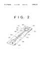
- FIG. 2is a perspective view of each of the head assemblies according to the first embodiment of the present invention.
- FIG. 3is a fragmentary cross-sectional view of an MR head of each of the head assemblies
- FIG. 4is an enlarged fragmentary perspective view of the head assembly according to the first embodiment of the present invention.
- FIG. 5is an enlarged fragmentary perspective view of a head assembly according to a second embodiment of the present invention.
- FIG. 6is a perspective view of a head assembly according to a third embodiment of the present invention.
- FIG. 7is an enlarged fragmentary perspective view of the head assembly according to the third embodiment of the present invention.
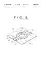
- FIG. 8is an enlarged fragmentary perspective view of a head assembly according to a fourth embodiment of the present invention.
- FIG. 9is an enlarged fragmentary perspective view of a head assembly according to a fifth embodiment of the present invention.
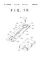
- FIG. 10is a perspective view of a head assembly according to a sixth embodiment of the present invention.
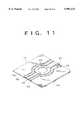
- FIG. 11is an enlarged fragmentary perspective view of the head assembly according to the sixth embodiment of the present invention.
- FIG. 12is a perspective view of a head assembly according to a modification of the first embodiment shown in FIG. 2.
- FIG. 1shows in exploded perspective view of a magnetic disk drive equipped with head assemblies according to a first embodiment of the present invention.
- the magnetic disk drivehas a housing (disk enclosure) 12 comprising a base 14 and a cover 16.
- the base 14supports thereon a spindle hub (not shown) rotatable by an inner hub motor.
- Magnetic disks 20 alternating with spacers (not shown)are mounted on the spindle hub, and fastened to the spindle hub by a disk clamp 18. The magnetic disks 20 thus mounted on the spindle hub are spaced along the spindle hub by the spacers.
- a rotary actuator 22comprises an actuator arm assembly 26 and a magnetic circuit 28.
- the actuator arm assembly 26is rotatably mounted on a shaft 24 fixedly mounted on the base 14.
- the actuator arm assembly 26includes a plurality of actuator arms 30 extending in one direction from the shaft 24 and a coil support 36 extending away from the actuator arms 30.
- the actuator arms 30support respective head assemblies 35 according to a first embodiment of the present invention on their respective tip ends.
- Each of the head assemblies 35comprises a head slider 32 and a suspension 34 which supports the head slider 32 on its tip end.
- the coil support 36supports a coil 38 thereon.
- the magnetic circuit 28 and the coil 38 which is inserted in a gap in the magnetic circuit 28jointly make up a voice coil motor (VCM) 40.
- VCMvoice coil motor
- a flexible printed circuit (FPC) 42 for transmitting signals from MR elements on the head sliders 32has one end fixed by a fixing member 44 and is electrically connected to a connector (not shown).
- the base 14supports an annular gasket assembly 46 extending on and along an upper edge thereof.
- the cover 16is fastened to the base 14 by screws with the annular gasket assembly 46 interposed therebetween, thereby sealing the housing 12.
- FIG. 2shows in perspective each of the head assemblies 35 according to the first embodiment of the present invention.
- the head slider 32which has an MR head 32a shown in detail in FIG. 3, is mounted on the tip end of the suspension 34 that is made of stainless steel, for example.
- the suspension 34has a hole 65 defined in its proximal end for attachment to the actuator arm 30.
- the MR head 32ahas an electrically conductive substrate 66 and a nonmagnetic insulating layer 68 made of alumina (Al 2 O 3 ), for example, which is disposed on the electrically conductive substrate 66.
- First and second magnetic shields 70, 72made of nickel-iron (Ni--Fe), for example, are embedded in the nonmagnetic insulating layer 68.
- the first and second magnetic shields 70, 72define a gap 74 therebetween at a tip end surface 75 (facing the magnetic disk 20) of the head 32a for increasing the resolution.
- a magnetoresistive element (MR element) 76made of nickel-iron (Ni--Fe), for example, in spaced relation to the tip end surface 75
- a front flux guide 78made of nickel-iron (Ni--Fe), for example, and having an end exposed at the tip end surface 75 and an opposite end magnetically coupled to the MR element 76.
- the front flux guide 78serves to guide magnetic fluxes from the recording medium (the magnetic disk 20) to the MR element 76.
- the MR element 76has a pair of terminals connected to a sense current source for supplying a constant sense current to the MR element 76.
- a magnetic pole 84 embedded in the nonmagnetic insulating layer 68has an end exposed at the tip end surface 75 and an opposite end coupled to the second magnetic shield 72.
- a conductor coil 82is wound substantially around the junction between the magnetic pole 84 and the second magnetic shield 72.
- the MR element 76is used to read information recorded on the magnetic disk 20. Specifically, a signal magnetic flux from a recording track on the magnetic disk 20 is received by the head 32a and introduced through the front flux guide 78 into the MR element 76, thereby magnetizing the MR element 76. The magnetic flux that has passed through the MR element 76 is absorbed through the rear flux guide 80 into the first and second magnetic shields 70, 72.
- the resistance of the MR element 76varies depending on a change in the magnitude of the signal magnetic flux. Since the MR element 76 is being supplied with a constant sense current from the sense current source, the voltage between the terminals of the MR element 76 varies as the resistance of the MR element 76 varies. Therefore, the information recorded on the magnetic disk 20 can be reproduced as a voltage signal from the MR element 76.
- an MR wiring pattern 48comprising a pair of lead lines 50, 52 and a coil wiring pattern 54 comprising a pair of lead lines 56, 78 are printed on the suspension 34.
- Each of the lead lines 50, 52, 56, 58is made of copper, for example.
- the lead lines 50, 52have ends connected to the terminals of the MR element 76, and the lead lines 56, 58 have ends connected to the coil 82.
- the suspension 34has a pair of ribs 62 (only one shown) integrally formed therewith along opposite side edges for increasing the rigidity of the suspension 34.
- a spacer 64is fixed by adhesive to the proximal end of the suspension 34.
- the lead lines 50, 52are connected to each other by an MR short circuit pattern 60.
- the MR short circuit pattern 60is made of such a material which can easily be broken after the head assembly 35 is installed on the actuator arm 30.
- the MR short circuit pattern 60is made of a solder material having a low melting point.
- the MR short circuit pattern 60is also heated, and can be blown off by compressed air or absorbed away under vacuum. Therefore, when the head assembly 35 is assembled, the lead lines 50, 52 are electrically disconnected from each other.
- the MR short circuit pattern 60is made of an alloy having a low melting point.
- a laser beamis applied to the MR short circuit pattern 60 to cut it off. Since the laser beam may be focused into a small spot, it can reliably cut off the MR short circuit pattern 60 even if the suspension 34 is small in size. Such a laser beam cutting process can easily be automatized.
- FIG. 5shows in enlarged fragmentary perspective a head assembly according to a second embodiment of the present invention.
- the head assembly according to the second embodimentdiffers from the head assembly according to the first embodiment in that it additionally has a ground line 86 disposed on the suspension 34 between the lead lines 50, 52 and connecting the first and second magnetic shields 70, 72 to ground.
- the lead lines 50, 52are connected to the ground line 86 by respective MR-shield short circuit patterns 88, 90, which are made of such a material which can easily be broken after the head assembly is installed on the actuator arm 30.
- lead lines 50, 52are connected to the ground line 86 by respective MR-shield short circuit patterns 88, 90 in the second embodiment shown in FIG. 5, the lead lines 50, 52 may be connected to the ground line 86 by a single continuous short circuit pattern.
- the suspension 34has a hole 94 defined in its proximal end behind a short circuit pattern 60a which interconnects the lead lines 50, 52.
- the actuator arm 30has a tooth or projection 92 on the distal end thereof for insertion into the hole 94 and a hole 31 defined in the distal end thereof for insertion of a pin 93 for attaching the head assembly 35 to the actuator arm 30.
- the pin 93is press-fitted through the hole 65 in the suspension 34 into the hole 31 in the actuator arm 30.
- the tooth 92is inserted into the hole 94 in the suspension 34, the short circuit pattern 60a is broken off by the tooth 92. Therefore, at the same time that the head assembly 35 is installed on the actuator arm 30, the short circuit pattern 60a is automatically broken off by the tooth 92.
- the head assembly 35can thus be assembled with ease.
- FIG. 8shows in enlarged fragmentary perspective a head assembly according to a fourth embodiment of the present invention.
- the lead lines 50, 52are selectively short-circuited and disconnected by a short circuit switch 96.
- the short circuit switch 96is made of a bimetal or a shape memory alloy. At a room temperature, the short circuit switch 96 is pressed against the lead lines 50, 52.
- this embodimentalso employs the tooth 92 that can be inserted into the hole 94 according to the third embodiment shown in FIGS. 6 and 7.
- the short circuit switch 96short-circuits the lead lines 50, 52 under normal conditions. However, when the head assembly 35 is installed on the actuator arm 30, the tooth 92 inserted into the hole 94 pushes upwardly the short circuit switch 96 as indicated by the imaginary lines in FIG. 8, thereby electrically disconnecting the lead lines 50, 52.
- FIG. 9shows in enlarged fragmentary perspective a head assembly according to a fifth embodiment of the present invention.
- the head assembly according to the fifth embodimentis similar to the head assembly according to the second embodiment except that the lead lines 50, 52 and the ground line 86 are selectively short-circuited or disconnected by two short circuit switches 98, 100.
- Each of the short circuit switches 98, 100is made of a bimetal or a shape memory alloy. At a room temperature, the short circuit switches 98, 100 are pressed against the lead lines 50, 52 and the ground line 86.
- this embodimentalso employs two teeth on the tip end of the actuator 30 and two holes defined in the suspension 34 behind the respective short circuit switches 98, 100 in a manner similar to the third embodiment shown in FIGS. 6 and 7.
- the teethare inserted into the respective holes, lifting the short circuit switches 98, 100 off the lead lines 50, 52 and the ground line 86, which are thus electrically disconnected from each other.
- FIG. 10shows in perspective a head assembly according to a sixth embodiment of the present invention.
- FIG. 11shows in enlarged fragmentary perspective the head assembly according to the sixth embodiment of the present invention.
- an inspection arm 102 of the magnetic disk drivehas a tooth 104 on the distal end thereof and a hole 103 defined in the distal end thereof for insertion of the pin 93.
- the suspension 34has a hole 94 defined in the proximal end thereof behind the short circuit switch 96 for insertion of the tooth 104.
- the short circuit switch 96is lifted off the lead lines 50, 52 by the tooth 104 inserted in the hole 94, thereby electrically disconnecting the lead lines 50, 52 from each other.
- the lead lines 50, 52are short-circuited by the short circuit switch 96 because the tooth 104 is retracted out of the hole 94. Therefore, even when the head assembly 35 needs to be installed and detached repeatedly for inspection until it is finally assembled, the MR element 76 is protected against being burned out.
- FIG. 12there is shown a modification of the first embodiment shown in FIG. 2.
- a tab 110 made of polyimideis suspended from the side edge of the suspension 34 and terminals 112, 114, 116 and 118 connected respectively to the lead lines 50, 52, 56 and 58 are formed on the tab 110.
- the lead lines 50 and 52 on the tab 110are connected to each other by an MR short circuit pattern 120.
- the MR short circuit pattern 120is made of, for example, solder material having a low meeting point.
- the MR short circuit pattern 1120is formed on the tab 110 suspended from the side edge of the suspension 34, it is easy to cut off the MR short circuit pattern 120 after a plurality of the head assemblies 35 are mounted on the respective actuator arms 30.
- the terminals 112, 114, 116 and 118are to be connected to terminals on an interconnection flexible printed circuit sheet which is to be bonded to a side face of the actuator arm 30.
- the present inventionhas been described with respect to the head assembly whose head slider has the MR element.
- the principles of the present inventionare also applicable to a head slider which has a general electromagnetic transducer for preventing the electromagnetic transducer from being adversely affected by electrostatic charge buildups.
- the terminals of the MR element and/or the terminals of the MR element and the magnetic shieldsare electrically short-circuited by the short circuit pattern or the short circuit switch, an excessive current produced due to an electrostatic charge flows through the short circuit pattern or the short circuit switch and is prevented from flowing through the MR element.
Landscapes
- Adjustment Of The Magnetic Head Position Track Following On Tapes (AREA)
- Supporting Of Heads In Record-Carrier Devices (AREA)
- Magnetic Heads (AREA)
Abstract
Description
Claims (12)
Applications Claiming Priority (2)
| Application Number | Priority Date | Filing Date | Title |
|---|---|---|---|
| JP03955397AJP3874875B2 (en) | 1997-02-24 | 1997-02-24 | Magnetic disk unit |
| JP9-039553 | 1997-02-24 |
Publications (1)
| Publication Number | Publication Date |
|---|---|
| US5991121Atrue US5991121A (en) | 1999-11-23 |
Family
ID=12556267
Family Applications (1)
| Application Number | Title | Priority Date | Filing Date |
|---|---|---|---|
| US08/905,327Expired - Fee RelatedUS5991121A (en) | 1997-02-24 | 1997-08-01 | Head assembly having short circuit pattern short-circuiting a pair of lead lines |
Country Status (2)
| Country | Link |
|---|---|
| US (1) | US5991121A (en) |
| JP (1) | JP3874875B2 (en) |
Cited By (11)
| Publication number | Priority date | Publication date | Assignee | Title |
|---|---|---|---|---|
| US6075676A (en)* | 1998-04-28 | 2000-06-13 | Fujitsu Limited | Head assembly including shorted head leads for preventing damage of head during manufacture of a magnetic storage system |
| US6160688A (en)* | 1997-12-16 | 2000-12-12 | Nec Corporation | Magneto-resistive composite head and a magnetic disk device, having grounded magnetic shielding layers |
| US6163443A (en)* | 1998-02-19 | 2000-12-19 | Fujitsu Limited | Actuator having MR element protecting means |
| US20010001588A1 (en)* | 1998-01-06 | 2001-05-24 | Robert T. J. Matz | Integrated lead head supension assembly having an etched laminated load beam and flexure with deposited conductors |
| US6275361B1 (en)* | 1999-05-13 | 2001-08-14 | Maxtor Corporation | Protecting a magnetoresistive head against electrostatic discharge |
| US6518521B1 (en) | 1999-09-02 | 2003-02-11 | Hutchinson Technology Incorporated | Switchable shunts for integrated lead suspensions |
| US20040022169A1 (en)* | 1998-11-13 | 2004-02-05 | Tdk Corporation | Write/read head supporting mechanism, and write/read system |
| US6700748B1 (en) | 2000-04-28 | 2004-03-02 | International Business Machines Corporation | Methods for creating ground paths for ILS |
| US6872896B1 (en) | 2001-09-12 | 2005-03-29 | Hutchinson Technology Incorporated | Elongated bridge shunt |
| US20050254176A1 (en)* | 2004-05-12 | 2005-11-17 | Mcreynolds Dave P | Disc drive integral actuator pins |
| US20060098367A1 (en)* | 2004-10-28 | 2006-05-11 | Hitachi Global Storage Technologies Netherlands B.V. | System, method, and apparatus for electrically testing lead-to-lead shorting during magnetoresistive sensor fabrication |
Families Citing this family (2)
| Publication number | Priority date | Publication date | Assignee | Title |
|---|---|---|---|---|
| US6326553B1 (en)* | 1998-10-16 | 2001-12-04 | Samsung Electronics, Co., Ltd | Scheme to avoid electrostatic discharge damage to MR/GMR head gimbal/stack assembly in hard disk applications |
| CN100351902C (en)* | 2001-12-29 | 2007-11-28 | 易拓控股公司 | Hard disk drive read and write magnetic sensor to eliminate overcurrent impact device |
Citations (15)
| Publication number | Priority date | Publication date | Assignee | Title |
|---|---|---|---|---|
| US4317149A (en)* | 1980-06-02 | 1982-02-23 | International Business Machines Corporation | Magnetic head having static discharge means |
| JPH04366409A (en)* | 1991-06-13 | 1992-12-18 | Fujitsu Ltd | Thin-film magnetic head and method for preventing its insulation breakdown |
| JPH07141636A (en)* | 1993-11-16 | 1995-06-02 | Alps Electric Co Ltd | Composite type magnetic head and fpc |
| US5465186A (en)* | 1994-01-26 | 1995-11-07 | International Business Machines Corporation | Shorted magnetoresistive head leads for electrical overstress and electrostatic discharge protection during manufacture of a magnetic storage system |
| US5467881A (en)* | 1994-06-28 | 1995-11-21 | International Business Machines Corporation | Method of manufacturing an MR read head which eliminates lead-to-shield shorts at the ABS of the MR read head |
| US5491605A (en)* | 1994-12-23 | 1996-02-13 | International Business Machines Corporation | Shorted magnetoresistive head elements for electrical overstress and electrostatic discharge protection |
| JPH08167123A (en)* | 1994-12-13 | 1996-06-25 | Hitachi Ltd | Magnetic head manufacturing method, substrate having magnetic head element group, and method of manufacturing substrate having magnetic head element group |
| US5539598A (en)* | 1994-12-08 | 1996-07-23 | International Business Machines Corporation | Electrostatic protection for a shielded MR sensor |
| JPH08315321A (en)* | 1995-05-16 | 1996-11-29 | Yamaha Corp | Connector structure of lead wire end of mr head |
| US5615072A (en)* | 1994-08-10 | 1997-03-25 | Thermik Geratebau Gmbh | Temperature-sensitive switch |
| US5638237A (en)* | 1995-08-25 | 1997-06-10 | International Business Machines Corporation | Fusible-link removable shorting of magnetoresistive heads for electrostatic discharge protection |
| US5644454A (en)* | 1996-03-11 | 1997-07-01 | International Business Machines Corporation | Electrostatic discharge protection system for MR heads |
| US5699212A (en)* | 1996-05-01 | 1997-12-16 | International Business Machines Corporation | Method of electrostatic discharge protection of magnetic heads in a magnetic storage system |
| US5754355A (en)* | 1995-09-21 | 1998-05-19 | International Business Machines Corporation | Disk drive apparatus and read error recovery method in a disk drive apparatus |
| US5759428A (en)* | 1996-03-15 | 1998-06-02 | International Business Machines Corporation | Method of laser cutting a metal line on an MR head |
- 1997
- 1997-02-24JPJP03955397Apatent/JP3874875B2/ennot_activeExpired - Fee Related
- 1997-08-01USUS08/905,327patent/US5991121A/ennot_activeExpired - Fee Related
Patent Citations (16)
| Publication number | Priority date | Publication date | Assignee | Title |
|---|---|---|---|---|
| US4317149A (en)* | 1980-06-02 | 1982-02-23 | International Business Machines Corporation | Magnetic head having static discharge means |
| JPH04366409A (en)* | 1991-06-13 | 1992-12-18 | Fujitsu Ltd | Thin-film magnetic head and method for preventing its insulation breakdown |
| JPH07141636A (en)* | 1993-11-16 | 1995-06-02 | Alps Electric Co Ltd | Composite type magnetic head and fpc |
| US5465186A (en)* | 1994-01-26 | 1995-11-07 | International Business Machines Corporation | Shorted magnetoresistive head leads for electrical overstress and electrostatic discharge protection during manufacture of a magnetic storage system |
| US5467881A (en)* | 1994-06-28 | 1995-11-21 | International Business Machines Corporation | Method of manufacturing an MR read head which eliminates lead-to-shield shorts at the ABS of the MR read head |
| US5615072A (en)* | 1994-08-10 | 1997-03-25 | Thermik Geratebau Gmbh | Temperature-sensitive switch |
| US5539598A (en)* | 1994-12-08 | 1996-07-23 | International Business Machines Corporation | Electrostatic protection for a shielded MR sensor |
| JPH08167123A (en)* | 1994-12-13 | 1996-06-25 | Hitachi Ltd | Magnetic head manufacturing method, substrate having magnetic head element group, and method of manufacturing substrate having magnetic head element group |
| US5491605A (en)* | 1994-12-23 | 1996-02-13 | International Business Machines Corporation | Shorted magnetoresistive head elements for electrical overstress and electrostatic discharge protection |
| JPH08315321A (en)* | 1995-05-16 | 1996-11-29 | Yamaha Corp | Connector structure of lead wire end of mr head |
| US5638237A (en)* | 1995-08-25 | 1997-06-10 | International Business Machines Corporation | Fusible-link removable shorting of magnetoresistive heads for electrostatic discharge protection |
| US5754355A (en)* | 1995-09-21 | 1998-05-19 | International Business Machines Corporation | Disk drive apparatus and read error recovery method in a disk drive apparatus |
| US5644454A (en)* | 1996-03-11 | 1997-07-01 | International Business Machines Corporation | Electrostatic discharge protection system for MR heads |
| US5710682A (en)* | 1996-03-11 | 1998-01-20 | International Business Machines Corporation | Electrostatic discharge protection system for MR heads |
| US5759428A (en)* | 1996-03-15 | 1998-06-02 | International Business Machines Corporation | Method of laser cutting a metal line on an MR head |
| US5699212A (en)* | 1996-05-01 | 1997-12-16 | International Business Machines Corporation | Method of electrostatic discharge protection of magnetic heads in a magnetic storage system |
Cited By (23)
| Publication number | Priority date | Publication date | Assignee | Title |
|---|---|---|---|---|
| US6160688A (en)* | 1997-12-16 | 2000-12-12 | Nec Corporation | Magneto-resistive composite head and a magnetic disk device, having grounded magnetic shielding layers |
| US20010001588A1 (en)* | 1998-01-06 | 2001-05-24 | Robert T. J. Matz | Integrated lead head supension assembly having an etched laminated load beam and flexure with deposited conductors |
| US6700747B2 (en)* | 1998-01-06 | 2004-03-02 | Hutchinson Technology Incorporated | Integrated lead head suspension assembly having an etched laminated load beam and flexure with deposited conductors |
| US6163443A (en)* | 1998-02-19 | 2000-12-19 | Fujitsu Limited | Actuator having MR element protecting means |
| US6075676A (en)* | 1998-04-28 | 2000-06-13 | Fujitsu Limited | Head assembly including shorted head leads for preventing damage of head during manufacture of a magnetic storage system |
| US20050254172A1 (en)* | 1998-11-13 | 2005-11-17 | Tdk Corporation | Write/read head supporting mechanism, and write/read system |
| US20040022169A1 (en)* | 1998-11-13 | 2004-02-05 | Tdk Corporation | Write/read head supporting mechanism, and write/read system |
| US7161765B2 (en)* | 1998-11-13 | 2007-01-09 | Tdk Corporation | Write/read head supporting mechanism, and write/read system |
| US7050266B2 (en)* | 1998-11-13 | 2006-05-23 | Tdk Corporation | Write/read head supporting mechanism and write/read system having a flexible grounding member |
| US6275361B1 (en)* | 1999-05-13 | 2001-08-14 | Maxtor Corporation | Protecting a magnetoresistive head against electrostatic discharge |
| US6518521B1 (en) | 1999-09-02 | 2003-02-11 | Hutchinson Technology Incorporated | Switchable shunts for integrated lead suspensions |
| US6723931B2 (en)* | 1999-09-02 | 2004-04-20 | Hutchinson Technology Inc. | Method of operating switchable shunts for integrated lead suspensions |
| US6700748B1 (en) | 2000-04-28 | 2004-03-02 | International Business Machines Corporation | Methods for creating ground paths for ILS |
| US6872896B1 (en) | 2001-09-12 | 2005-03-29 | Hutchinson Technology Incorporated | Elongated bridge shunt |
| US7041920B1 (en) | 2001-09-12 | 2006-05-09 | Hutchinson Technology Incorporated | Elongated bridge shunt switch formed by stretching and rupturing a conducting bridge |
| US20060180444A1 (en)* | 2001-09-12 | 2006-08-17 | Hutchinson Technology Incorporated | Elongated bridge shunt formed by stretching and rupturing a conducting bridge |
| US7230194B2 (en) | 2001-09-12 | 2007-06-12 | Hutchinson Technology Incorporated | Elongated bridge shunt formed by stretching and rupturing a conducting bridge |
| US20050254176A1 (en)* | 2004-05-12 | 2005-11-17 | Mcreynolds Dave P | Disc drive integral actuator pins |
| US7355818B2 (en) | 2004-05-12 | 2008-04-08 | Seagate Technology Llc | Disc drive integral actuator pins |
| US20060098367A1 (en)* | 2004-10-28 | 2006-05-11 | Hitachi Global Storage Technologies Netherlands B.V. | System, method, and apparatus for electrically testing lead-to-lead shorting during magnetoresistive sensor fabrication |
| US7282376B2 (en) | 2004-10-28 | 2007-10-16 | Hitachi Global Storage Technologies Netherlands Bv | System, method, and apparatus for electrically testing lead-to-lead shorting during magnetoresistive sensor fabrication |
| US20070290694A1 (en)* | 2004-10-28 | 2007-12-20 | Mr. Arley Cleveland | System and apparatus for electrically testing lead-to-lead shorting during magnetoresistive sensor fabrication |
| US7737703B2 (en) | 2004-10-28 | 2010-06-15 | Hitachi Global Storage Technologies Netherlands B.V. | System and apparatus for electrically testing lead-to-lead shorting during magnetoresistive sensor fabrication |
Also Published As
| Publication number | Publication date |
|---|---|
| JPH10241132A (en) | 1998-09-11 |
| JP3874875B2 (en) | 2007-01-31 |
Similar Documents
| Publication | Publication Date | Title |
|---|---|---|
| KR100269903B1 (en) | Actuator having mr element protecting means | |
| US6075676A (en) | Head assembly including shorted head leads for preventing damage of head during manufacture of a magnetic storage system | |
| US6404706B1 (en) | Laser mounting for a thermally assisted GMR head | |
| US7006330B1 (en) | Head stack assembly including a ground conductive pad for grounding a slider to a gimbal | |
| US5991121A (en) | Head assembly having short circuit pattern short-circuiting a pair of lead lines | |
| US6160688A (en) | Magneto-resistive composite head and a magnetic disk device, having grounded magnetic shielding layers | |
| US6377411B1 (en) | Head IC, head amplifier circuit, head suspension assembly, and magnetic disk drive for avoiding electrostatic breakdown of magnetic head | |
| JPH0367314B2 (en) | ||
| US5978176A (en) | Magnetic head for a magnetic disk having a slider with indented portions for providing heat dissipation | |
| US6614624B2 (en) | Suspension and head gimbal assembly with the suspension | |
| US6836391B2 (en) | Magnetic head slider and magnetic head assembly with short-circuiting switching element | |
| EP0811967A2 (en) | Magnetic head unit, method of manufacturing the same and magnetic recording and reproducing apparatus using the same | |
| US6507467B1 (en) | Comb shunt for ESD protection | |
| US4750071A (en) | Magnetic head assembly including a pair of heads disposed in the vicinity of each other | |
| JP4054801B2 (en) | Interconnect circuit that dissipates static charge on head slider, electrostatic voltage dissipation method | |
| JPH1145423A (en) | Magnetic head slider and magnetic head assembly | |
| US6650519B1 (en) | ESD protection by a high-to-low resistance shunt | |
| JP3224752B2 (en) | Magnetoresistive head including low reluctance paths selectively located between shields | |
| JP4081937B2 (en) | Manufacturing method of rotary magnetic head device | |
| US7859796B2 (en) | Disk drive and arm coil support assembly | |
| JPS61144712A (en) | Magnetic head | |
| KR0155046B1 (en) | Devices for Improving Conductivity from Thin Film Heads in Hard Disk Drives | |
| JPH0444610A (en) | Composite thin film magnetic head and its manufacturing method | |
| JP2752900B2 (en) | Head carriage assembly | |
| JPH1186253A (en) | Magnetic disk storage |
Legal Events
| Date | Code | Title | Description |
|---|---|---|---|
| AS | Assignment | Owner name:FUJITSU LIMITED, JAPAN Free format text:ASSIGNMENT OF ASSIGNORS INTEREST;ASSIGNOR:KANDA, EIICHI;REEL/FRAME:008666/0275 Effective date:19970718 | |
| FEPP | Fee payment procedure | Free format text:PAYOR NUMBER ASSIGNED (ORIGINAL EVENT CODE: ASPN); ENTITY STATUS OF PATENT OWNER: LARGE ENTITY | |
| CC | Certificate of correction | ||
| FPAY | Fee payment | Year of fee payment:4 | |
| FPAY | Fee payment | Year of fee payment:8 | |
| AS | Assignment | Owner name:TOSHIBA STORAGE DEVICE CORPORATION, JAPAN Free format text:ASSIGNMENT OF ASSIGNORS INTEREST;ASSIGNOR:FUJITSU LIMITED;REEL/FRAME:023419/0031 Effective date:20091014 Owner name:TOSHIBA STORAGE DEVICE CORPORATION, JAPAN Free format text:ASSIGNMENT OF ASSIGNORS INTEREST;ASSIGNOR:FUJITSU LIMITED;REEL/FRAME:023861/0881 Effective date:20091014 Owner name:TOSHIBA STORAGE DEVICE CORPORATION,JAPAN Free format text:ASSIGNMENT OF ASSIGNORS INTEREST;ASSIGNOR:FUJITSU LIMITED;REEL/FRAME:023861/0881 Effective date:20091014 | |
| XAS | Not any more in us assignment database | Free format text:ASSIGNMENT OF ASSIGNORS INTEREST;ASSIGNOR:FUJITSU LIMITED;REEL/FRAME:023419/0031 | |
| REMI | Maintenance fee reminder mailed | ||
| LAPS | Lapse for failure to pay maintenance fees | ||
| STCH | Information on status: patent discontinuation | Free format text:PATENT EXPIRED DUE TO NONPAYMENT OF MAINTENANCE FEES UNDER 37 CFR 1.362 | |
| FP | Lapsed due to failure to pay maintenance fee | Effective date:20111123 |