US5991015A - Beam monitoring assembly - Google Patents
Beam monitoring assemblyDownload PDFInfo
- Publication number
- US5991015A US5991015AUS09/167,292US16729298AUS5991015AUS 5991015 AUS5991015 AUS 5991015AUS 16729298 AUS16729298 AUS 16729298AUS 5991015 AUS5991015 AUS 5991015A
- Authority
- US
- United States
- Prior art keywords
- split
- far
- mounting plate
- field
- receive
- Prior art date
- Legal status (The legal status is an assumption and is not a legal conclusion. Google has not performed a legal analysis and makes no representation as to the accuracy of the status listed.)
- Expired - Lifetime
Links
- 238000012544monitoring processMethods0.000titleclaimsabstractdescription26
- 230000003287optical effectEffects0.000claimsdescription22
- 238000001816coolingMethods0.000claimsdescription8
- 230000007935neutral effectEffects0.000claimsdescription3
- 239000012809cooling fluidSubstances0.000claimsdescription2
- 238000003384imaging methodMethods0.000abstractdescription4
- 238000005259measurementMethods0.000abstractdescription4
- 238000012795verificationMethods0.000abstractdescription4
- 238000000034methodMethods0.000abstractdescription3
- 238000003754machiningMethods0.000description13
- 238000003466weldingMethods0.000description7
- 238000003491arrayMethods0.000description6
- 239000007787solidSubstances0.000description6
- 238000005520cutting processMethods0.000description5
- 238000005553drillingMethods0.000description5
- 239000000463materialSubstances0.000description5
- 238000012545processingMethods0.000description4
- 238000004891communicationMethods0.000description3
- 239000011521glassSubstances0.000description3
- 229910052751metalInorganic materials0.000description3
- 239000002184metalSubstances0.000description3
- 238000005086pumpingMethods0.000description3
- 229910000831SteelInorganic materials0.000description2
- 229910052782aluminiumInorganic materials0.000description2
- XAGFODPZIPBFFR-UHFFFAOYSA-NaluminiumChemical compound[Al]XAGFODPZIPBFFR-UHFFFAOYSA-N0.000description2
- 238000004519manufacturing processMethods0.000description2
- 239000010959steelSubstances0.000description2
- 229910019655synthetic inorganic crystalline materialInorganic materials0.000description2
- RYGMFSIKBFXOCR-UHFFFAOYSA-NCopperChemical compound[Cu]RYGMFSIKBFXOCR-UHFFFAOYSA-N0.000description1
- 229910052779NeodymiumInorganic materials0.000description1
- 238000010521absorption reactionMethods0.000description1
- 239000011149active materialSubstances0.000description1
- 230000009286beneficial effectEffects0.000description1
- 229910052802copperInorganic materials0.000description1
- 239000010949copperSubstances0.000description1
- 239000013078crystalSubstances0.000description1
- 230000003247decreasing effectEffects0.000description1
- 230000000694effectsEffects0.000description1
- 238000010304firingMethods0.000description1
- 239000012530fluidSubstances0.000description1
- 230000004927fusionEffects0.000description1
- 238000010438heat treatmentMethods0.000description1
- 230000002452interceptive effectEffects0.000description1
- 238000012986modificationMethods0.000description1
- 230000004048modificationEffects0.000description1
- QEFYFXOXNSNQGX-UHFFFAOYSA-Nneodymium atomChemical compound[Nd]QEFYFXOXNSNQGX-UHFFFAOYSA-N0.000description1
- -1neodymium yttrium aluminumChemical compound0.000description1
- 230000005855radiationEffects0.000description1
- 229910052594sapphireInorganic materials0.000description1
- 239000010980sapphireSubstances0.000description1
- 230000000007visual effectEffects0.000description1
- XLYOFNOQVPJJNP-UHFFFAOYSA-NwaterSubstancesOXLYOFNOQVPJJNP-UHFFFAOYSA-N0.000description1
- 229910019901yttrium aluminum garnetInorganic materials0.000description1
Images
Classifications
- G—PHYSICS
- G01—MEASURING; TESTING
- G01B—MEASURING LENGTH, THICKNESS OR SIMILAR LINEAR DIMENSIONS; MEASURING ANGLES; MEASURING AREAS; MEASURING IRREGULARITIES OF SURFACES OR CONTOURS
- G01B11/00—Measuring arrangements characterised by the use of optical techniques
- G01B11/26—Measuring arrangements characterised by the use of optical techniques for measuring angles or tapers; for testing the alignment of axes
- G01B11/27—Measuring arrangements characterised by the use of optical techniques for measuring angles or tapers; for testing the alignment of axes for testing the alignment of axes
- G01B11/272—Measuring arrangements characterised by the use of optical techniques for measuring angles or tapers; for testing the alignment of axes for testing the alignment of axes using photoelectric detection means
Definitions
- This inventionrelates generally to a beam monitoring assembly that monitors a laser beam for alignment and performance verification purposes and, more particularly, to a beam monitoring assembly that provides real time, non-intrusive monitoring of the near-field and far-field spacial mode and beam power of a laser beam using beam optics included in a laser head enclosure.
- a solid state slab laserwill include one or more gain modules each having a solid state laser gain medium, such as a crystal of neodymium yttrium aluminum garnet (Nd:YAG), Yb:YAG, Ti: sapphire or neodymium glass (Nd:glass), and an optical pumping source to produce a population inversion in the gain medium.
- the gain mediumtypically has a slab configuration with a rectangular cross-section, an optically polished major side and end faces.
- the optical pumping sourcegenerally is one or more diode arrays positioned adjacent to the side faces of the slab.
- the laser gain mediumabsorbs light radiation from the diode arrays to create a population inversion within the medium to produce a laser beam output.
- the end faces of the slabare preferably formed at a non-perpendicular angle to the side faces so that light travels longitudinally in a zig-zag pattern through the laser gain medium as it is reflected off of the side faces.
- a high power solid state slab laser of this typeis disclosed in U.S. Pat. No. 5,555,254 issued to Injeyan et al., Sep. 10, 1996, and U.S. Pat. application Ser. No. 08/683,585, filed Jul. 15, 1996, titled "Diode Laser Pumped Solid State Laser Gain Module", and assigned to the assignee of the instant invention.
- the diode arraysare switched on and off or pumped in a controlled manner to generate a pulsed laser beam emitted from the gain medium that has a particular pulse rate and pulse width.
- the light output of the diode arrayscan be accurately tuned to the absorption line of the active material of the laser gain medium to achieve a high pumping efficiency.
- An increase in the pulse rate and/or pulse widthincreases the power output of the laser beam.
- the diode arraysare fired in a controlled manner to set the pulse width and pulse rate of the output beam.
- the firing of the various diode arrays for multiple gain modulescan be controlled independently of each other in sequence to further control the overall pulse width and rate for the laser beam, or generate a continuous wave (CW) beam. Therefore, depending on the particular application, the pulse rate and pulse width of the beam output is controlled for efficient laser operation for that application.
- CWcontinuous wave
- a single machining operationmay include various degrees of cutting, welding, and drilling of a single workpiece or multiple workpieces.
- the machining operationmay require a welding operation and then immediately thereafter, drilling of a series of holes and/or cutting the workpiece.
- the welding operationgenerally requires different power levels than cutting and drilling operations, and the welding process itself may require different laser power levels.
- the lasercan be calibrated to weld a certain material, such as steel. If the operator then changes to a different material, such as a different steel, aluminum, copper, etc., different laser settings and output parameters would be required.
- the near-field imageis the image of the beam as it leaves the laser
- the far-field imageis the image of the beam at its focus, such as when it contacts the workpiece.
- the near-field image of the beamneeds to have a high degree of intensity and wave front uniformity
- the far-field imageneeds to have a high degree of beam circularity and intensity uniformity.
- Optical systemsare known for displaying the near-field and far-field images of a laser beam.
- these optical systemsare typically large compared to the laser itself, and are not readily compatible to being combined with existing laser systems because of cost, complexity and size.
- a beam monitoring assemblythat provides near-field imaging, far-field imaging and power measurements of a laser beam in real-time for alignment and performance verification purposes.
- the monitoring assemblyincludes a holographic beam splitter that splits the laser beam from the laser into a series of separate split beams having varying beam powers. A portion of this beam is directed to a power meter to measure the power of the beam.
- One of the split beamsis directed to a near-field camera that provides a near-field image of the beam.
- Another one of the split beamsis directed to a far-field lens that focuses the split beam onto a far-field camera that provides a far-field image of the beam.
- the near-field and far-field images of the beamare displayed on an operator control panel in real-time.
- Suitable computer electronics and camera electronicsare provided to process the electrical signals from the power meter and cameras.
- the beam splitter, near-field and far-field cameras, power meter and other optics and electronicsare mounted to a common base plate, all positioned within a common housing of a compact size suitable to fit in a laser head enclosure.
- the base plateis cooled by a suitable cooling system to reduce inaccuracies caused by heating of the optical components.
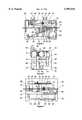
- FIG. 1is a top plan view of a beam monitoring assembly according to an embodiment of the present invention
- FIG. 2is an end plan view of the beam monitoring assembly shown in FIG. 1;
- FIG. 3is a side plan view of the beam monitoring assembly shown in FIG. 1.
- FIG. 1shows a top plan view
- FIG. 2shows an end plan view
- FIG. 3shows a side plan view of a beam monitoring assembly 10 according to the invention.
- the beam monitoring assembly 10is positioned in the path of a laser beam 12 generated by a laser (not shown) to provide a near-field image, a far-field image and a power measurement of the beam 12 during real time operation of the laser.
- the assembly 10can be used with any type of suitable laser, and has a particular application for a diode slab laser (discussed above) used in PLM operations.
- the assembly 10is intended to be included within a laser head enclosure as an accessory, and is thus compact in size for this purpose.
- Diode slab lasers of the type used in PLM operationstypically include a control panel (not shown) that an operator of the machining operation uses to control the machining process.
- the control panelwould include processing circuitry and display devices to allow the operator to view the near-field and far-field images, and the power measurement of the beam 12 for resonator cavity alignment and during the machining process for performance verification.
- the assembly 10includes various optical components secured to a common base plate 14 by bolts or the like within a metal housing 16.
- the base plate 14has different levels, as shown, to accommodate the positioning of the various optical components within the housing 16, as will be described in more detail below.
- the housing 16is mounted to an optical bench (not shown) by three mounting brackets 18 at a location just beyond the laser resonator cavity (not shown) so that entrance and exit apertures (not shown) in the ends of the housing 16 are aligned with the laser beam 12.
- the laser beam 12enters the housing 16 through the entrance aperture in an end plate 20, and exits the housing through the exit aperture in an end plate 22.
- the beam 12enters the housing 16 and contacts a holographic beam splitter 24 that is bolted to the base plate 14 in a position relative to the entrance aperture.
- the beam splitter 24is a commercially available optical product from Gentec, Inc. of Quebec, Canada, and its operation is well known to those skilled in the art. In one embodiment, most of the intensity of the beam 12 passes straight through the beam splitter 24, where about 0.2% of the beam 12 is split off.
- the beam splitter 24operates by emitting a split beam on each side of the laser beam 12 every 10° relative to the propagation direction of the laser beam 12 in a fanning out type arrangement. Split beams at greater angles from the laser beam 12, successively drop off in intensity by about three magnitudes.
- a first split beam 28 and a second split beam 30are separated from the laser beam 12, and are directed about 10° relative to the direction of the beam 12 on each side of the beam 12. Both of the split beams 28 and 30 have an intensity of about 1 ⁇ 10 -3 of the intensity of the beam 12.
- a third split beam 32is separated from the laser beam 12 in a direction of about 20° relative to the propagation direction of the beam 12, and has an intensity of about 1 ⁇ 10 -6 of the intensity of the beam 12. Although not shown, this pattern of split beam continues out from the beam splitter 24 with decreasing intensity. The other beams are not shown, and because their intensity is so low, they do not interfere with the operation of the monitoring assembly 10.
- the split beam 28contacts an optical splitter in a mount 34, such as a glass wedge, that is bolted to the base plate 14. Most of the intensity of the split beam 28 passes through the splitter 34 and contacts a power meter 36, also bolted to the base plate 14 in the appropriate position.
- the power meter 36is a known optical power meter also available from Gentec, Inc. and has part number PS310. In this embodiment, the power meter 36 has a diameter of about two inches.
- the power meter 36generates an electrical signal based on the intensity of the split beam 28 that is then processed and displayed on the operator control panel. Because the proportionality of the split portion of the beam 28 from the laser beam 12 is known, the power of the laser beam 12 can be determined in real-time to more accurately monitor the machining operation.
- a computer communications electronics unit 38is mounted to the base plate 14 by a mounting structure 52, and provides the electronics for processing the signals from the power meter 36.
- the communications electronics unit 38is a remote modulator data acquisition that provides an analog to RS485 communications computer connection, and is available from Industrial Computer Source of San Diego, Calif.
- a portion of the split beam 28(approximately 2-3%) is reflected from the splitter 34, and is directed towards a near-field camera 42 bolted to the base plate 14 in a position to be in line with the reflected portion of the beam 28.
- the reflected beam 28passes through a series of neutral density filters 44 in front of the camera 42 to reduce the intensity of the reflected beam 28 to prevent saturation of the camera 42.
- the near-field camera 42is a commercially available camera from Cohu of San Diego, Calif.
- the camera 42provides electrical signals indicative of an image of the split beam 28, which is a reproduction of the laser beam 12, that is displayed on the operator control panel.
- the split beam 32impinges a far-field lens 46 bolted to the base plate 14 in a position to be aligned with the beam 32.
- the lens 46is a 300 mm focusing lens to provide the far-field focusing, and produce a representation of the beam 12 as it would appear at the workpiece (not shown).
- the focused beam 32is reflected off of a mounted reflector 48, also bolted to the base plate 14, and is directed to a far-field camera 50.
- the far-field camera 50is also bolted to the base plate 14 in a position to be aligned with the focused and reflected beam 32.
- the lens 46focuses the image of the laser beam 12 onto the optics of the far-field camera 50 to generate a far-field image of the laser beam 12.
- the far-field camera 50is also available from Cohu. As is apparent, because the split beam 28 is one beam away from the laser beam 12, and the split beam 32 is two beams away from the laser beam 12, the intensity of the split beam 32 is three magnitudes in intensity lower than the intensity of the split beam 28. Of course, as discussed above, the intensity of the beam that actually contacts the near-field camera 42 is much less than the intensity of the split beam 28 because of the operation of the splitter 34.
- the split beam 30is not used by the monitoring assembly 10, and is therefore sent to a heat dump 52 that is bolted to the base plate 14.
- the heat dump 52can be any optical collector, such as a block of aluminum, that is suitable to collect the beam 30. It is necessary to collect the beam 30 to prevent it from interfering with the operation of the assembly 10 because it has a significantly higher power than the other beams split from the splitter 24.
- a cooling tube 54acts to cool the base plate 14 to increase the accuracy of the assembly 10.
- the cooling tube 54is soldered to a metal block 56 that is bolted to the base plate 14. By running a cooling fluid, such as water from a fluid source (not shown), through the tube 54, the base plate 14 can be suitably cooled to reduce the heat build-up within the housing 16.
- Two camera electronics units 58are supported by a metal tray, 91, located under and bolted to the base plate 14 by bolts outside of the housing 16 and between the mounting brackets 18. Each camera electronics unit 58 receives the electrical signals from the near-field camera 42 and the far-field camera 50 over electrical cables 60 and 62, respectively.
- the camera electronics units 58are connected to the control panel by electrical cables (not shown) attached at electrical connectors 64 and 66 to connect the camera electronics 58 to the control panel.
- the beam monitoring assembly 10 of the inventionis intended to be of a compact size suitable to be positioned within a laser head enclosure, such as the enclosure for a diode slab laser.
- the laser beam 12has a beam height of about 0.35 inches, and the distance between the bottom of the brackets 18 and the center of the beam 12 is about 4.675 inches.
- the assembly 10has a length of about 12.9 inches, a width of about 7.4 inches and a height of about 8.7 inches.
Landscapes
- Physics & Mathematics (AREA)
- General Physics & Mathematics (AREA)
- Photometry And Measurement Of Optical Pulse Characteristics (AREA)
Abstract
Description
Claims (19)
Priority Applications (1)
| Application Number | Priority Date | Filing Date | Title |
|---|---|---|---|
| US09/167,292US5991015A (en) | 1998-10-06 | 1998-10-06 | Beam monitoring assembly |
Applications Claiming Priority (1)
| Application Number | Priority Date | Filing Date | Title |
|---|---|---|---|
| US09/167,292US5991015A (en) | 1998-10-06 | 1998-10-06 | Beam monitoring assembly |
Publications (1)
| Publication Number | Publication Date |
|---|---|
| US5991015Atrue US5991015A (en) | 1999-11-23 |
Family
ID=22606757
Family Applications (1)
| Application Number | Title | Priority Date | Filing Date |
|---|---|---|---|
| US09/167,292Expired - LifetimeUS5991015A (en) | 1998-10-06 | 1998-10-06 | Beam monitoring assembly |
Country Status (1)
| Country | Link |
|---|---|
| US (1) | US5991015A (en) |
Cited By (12)
| Publication number | Priority date | Publication date | Assignee | Title |
|---|---|---|---|---|
| US6081544A (en)* | 1998-04-08 | 2000-06-27 | Trw Inc. | Flexure mounting of optical resonator for precision lasers |
| US6201214B1 (en)* | 1998-02-19 | 2001-03-13 | M. J. Technologies, Limited | Laser drilling with optical feedback |
| US6313910B1 (en)* | 1998-09-11 | 2001-11-06 | Dataray, Inc. | Apparatus for measurement of optical beams |
| US6793494B2 (en)* | 2000-06-19 | 2004-09-21 | Cubic Corporation | Method of aligning a laser beam of a SAT |
| US20060138351A1 (en)* | 2004-12-24 | 2006-06-29 | Masayuki Jyumonji | Laser anneal apparatus |
| US20100155382A1 (en)* | 2005-08-05 | 2010-06-24 | Valeo Thermal Systems Japan Corporation | Method for Machining Valve Mechanism Component Member |
| US20110176068A1 (en)* | 2010-01-20 | 2011-07-21 | Microvision, Inc. | Closed Loop Feedback for Electronic Beam Alignment |
| US20110259862A1 (en)* | 2008-09-05 | 2011-10-27 | Mtt Technologies Limited | Additive Manufacturing Apparatus with a Chamber and a Removably-Mountable Optical Module; Method of Preparing a Laser Processing Apparatus with such Removably-Mountable Optical Module |
| US20140125760A1 (en)* | 2012-11-05 | 2014-05-08 | Honeywell International Inc. | Visual system having multiple cameras |
| CN115032847A (en)* | 2022-08-10 | 2022-09-09 | 中国工程物理研究院应用电子学研究所 | Sum frequency light output device |
| US11446774B2 (en) | 2015-10-30 | 2022-09-20 | Seurat Technologies, Inc. | Dynamic optical assembly for laser-based additive manufacturing |
| US12162074B2 (en) | 2020-11-25 | 2024-12-10 | Lawrence Livermore National Security, Llc | System and method for large-area pulsed laser melting of metallic powder in a laser powder bed fusion application |
Citations (2)
| Publication number | Priority date | Publication date | Assignee | Title |
|---|---|---|---|---|
| US5408318A (en)* | 1993-08-02 | 1995-04-18 | Nearfield Systems Incorporated | Wide range straightness measuring stem using a polarized multiplexed interferometer and centered shift measurement of beam polarization components |
| US5872626A (en)* | 1997-09-16 | 1999-02-16 | Lockheed Martin Corporation | Consolidated laser alignment and test station |
- 1998
- 1998-10-06USUS09/167,292patent/US5991015A/ennot_activeExpired - Lifetime
Patent Citations (2)
| Publication number | Priority date | Publication date | Assignee | Title |
|---|---|---|---|---|
| US5408318A (en)* | 1993-08-02 | 1995-04-18 | Nearfield Systems Incorporated | Wide range straightness measuring stem using a polarized multiplexed interferometer and centered shift measurement of beam polarization components |
| US5872626A (en)* | 1997-09-16 | 1999-02-16 | Lockheed Martin Corporation | Consolidated laser alignment and test station |
Cited By (17)
| Publication number | Priority date | Publication date | Assignee | Title |
|---|---|---|---|---|
| US6201214B1 (en)* | 1998-02-19 | 2001-03-13 | M. J. Technologies, Limited | Laser drilling with optical feedback |
| US6081544A (en)* | 1998-04-08 | 2000-06-27 | Trw Inc. | Flexure mounting of optical resonator for precision lasers |
| US6313910B1 (en)* | 1998-09-11 | 2001-11-06 | Dataray, Inc. | Apparatus for measurement of optical beams |
| US6793494B2 (en)* | 2000-06-19 | 2004-09-21 | Cubic Corporation | Method of aligning a laser beam of a SAT |
| US20060138351A1 (en)* | 2004-12-24 | 2006-06-29 | Masayuki Jyumonji | Laser anneal apparatus |
| US7550694B2 (en)* | 2004-12-24 | 2009-06-23 | Advanced Lcd Technologies Development Center Co., Ltd. | Laser anneal apparatus |
| US20100155382A1 (en)* | 2005-08-05 | 2010-06-24 | Valeo Thermal Systems Japan Corporation | Method for Machining Valve Mechanism Component Member |
| US20110259862A1 (en)* | 2008-09-05 | 2011-10-27 | Mtt Technologies Limited | Additive Manufacturing Apparatus with a Chamber and a Removably-Mountable Optical Module; Method of Preparing a Laser Processing Apparatus with such Removably-Mountable Optical Module |
| US9114478B2 (en)* | 2008-09-05 | 2015-08-25 | Mtt Technologies Limited | Additive manufacturing apparatus with a chamber and a removably-mountable optical module; method of preparing a laser processing apparatus with such removably-mountable optical module |
| US20110176068A1 (en)* | 2010-01-20 | 2011-07-21 | Microvision, Inc. | Closed Loop Feedback for Electronic Beam Alignment |
| WO2011090884A3 (en)* | 2010-01-20 | 2011-11-24 | Microvision, Inc. | Closed loop feedback for electronic beam alignment |
| US8675141B2 (en) | 2010-01-20 | 2014-03-18 | Microvision, Inc. | Closed loop feedback for electronic beam alignment |
| US20140125760A1 (en)* | 2012-11-05 | 2014-05-08 | Honeywell International Inc. | Visual system having multiple cameras |
| US9338370B2 (en)* | 2012-11-05 | 2016-05-10 | Honeywell International Inc. | Visual system having multiple cameras |
| US11446774B2 (en) | 2015-10-30 | 2022-09-20 | Seurat Technologies, Inc. | Dynamic optical assembly for laser-based additive manufacturing |
| US12162074B2 (en) | 2020-11-25 | 2024-12-10 | Lawrence Livermore National Security, Llc | System and method for large-area pulsed laser melting of metallic powder in a laser powder bed fusion application |
| CN115032847A (en)* | 2022-08-10 | 2022-09-09 | 中国工程物理研究院应用电子学研究所 | Sum frequency light output device |
Similar Documents
| Publication | Publication Date | Title |
|---|---|---|
| US6163010A (en) | Method and apparatus for laser cutting materials | |
| US5991015A (en) | Beam monitoring assembly | |
| EP1008212B1 (en) | High efficiency, high power direct diode laser systems and methods therefor | |
| US5059764A (en) | Diode-pumped, solid state laser-based workstation for precision materials processing and machining | |
| US6184490B1 (en) | Material irradiation apparatus with a beam source that produces a processing beam for a workpiece, and a process for operation thereof | |
| US5280491A (en) | Two dimensional scan amplifier laser | |
| US7102118B2 (en) | Beam formation unit comprising two axicon lenses, and device comprising one such beam formation unit for introducing radiation energy into a workpiece consisting of a weakly-absorbent material | |
| US4927226A (en) | Multiplexer for high power CW lasers | |
| WO2003007679B1 (en) | High intensity and high power solid state laser amplifying system and method | |
| US6266198B1 (en) | Consolidated laser alignment and test station | |
| KR20070096847A (en) | Laser processing equipment | |
| EP0961688A1 (en) | Device for laser writing on materials | |
| KR20160091243A (en) | Laser beam amplification by homogenous pumping of an amplification medium | |
| US7495191B2 (en) | Laser treatment apparatus | |
| EP0580867B1 (en) | Laser | |
| RU2004112773A (en) | LASER CUTTING MACHINE FOR DIAMONDS | |
| EP0770448B1 (en) | Method and apparatus for laser cutting materials | |
| WO1997015417A1 (en) | Method and apparatus for laser cutting materials | |
| Beck et al. | Beam addition of Nd: YAG high-power lasers | |
| KR100479890B1 (en) | Laser based apparatus for precision processing and machining of materials, and method for cutting a manufactured object | |
| Hübner et al. | Compact 1kW diode laser module emitting at 780nm for the efficient direct additive manufacturing of aluminum | |
| JPH05104266A (en) | Laser processing equipment | |
| CN120497742A (en) | Solid resonant cavity adjusting device and method for medium infrared femtosecond laser generation | |
| CA2234895A1 (en) | Method and apparatus for laser cutting materials | |
| JP3257489B2 (en) | Laser processing equipment |
Legal Events
| Date | Code | Title | Description |
|---|---|---|---|
| AS | Assignment | Owner name:TRW INC., CALIFORNIA Free format text:ASSIGNMENT OF ASSIGNORS INTEREST;ASSIGNORS:ZAMEL, JAMES M.;SZOT, JOHN A.;MOYER, RICHARD H.;REEL/FRAME:009515/0228 Effective date:19981005 | |
| STCF | Information on status: patent grant | Free format text:PATENTED CASE | |
| AS | Assignment | Owner name:NORTHROP GRUMMAN CORPORATION, CALIFORNIA Free format text:ASSIGNMENT OF ASSIGNORS INTEREST;ASSIGNOR:TRW, INC. N/K/A NORTHROP GRUMMAN SPACE AND MISSION SYSTEMS CORPORATION, AN OHIO CORPORATION;REEL/FRAME:013751/0849 Effective date:20030122 Owner name:NORTHROP GRUMMAN CORPORATION,CALIFORNIA Free format text:ASSIGNMENT OF ASSIGNORS INTEREST;ASSIGNOR:TRW, INC. N/K/A NORTHROP GRUMMAN SPACE AND MISSION SYSTEMS CORPORATION, AN OHIO CORPORATION;REEL/FRAME:013751/0849 Effective date:20030122 | |
| FPAY | Fee payment | Year of fee payment:4 | |
| REMI | Maintenance fee reminder mailed | ||
| FPAY | Fee payment | Year of fee payment:8 | |
| FEPP | Fee payment procedure | Free format text:PAYOR NUMBER ASSIGNED (ORIGINAL EVENT CODE: ASPN); ENTITY STATUS OF PATENT OWNER: LARGE ENTITY | |
| AS | Assignment | Owner name:NORTHROP GRUMMAN SPACE & MISSION SYSTEMS CORP.,CAL Free format text:ASSIGNMENT OF ASSIGNORS INTEREST;ASSIGNOR:NORTHROP GRUMMAN CORPORTION;REEL/FRAME:023699/0551 Effective date:20091125 Owner name:NORTHROP GRUMMAN SPACE & MISSION SYSTEMS CORP., CA Free format text:ASSIGNMENT OF ASSIGNORS INTEREST;ASSIGNOR:NORTHROP GRUMMAN CORPORTION;REEL/FRAME:023699/0551 Effective date:20091125 | |
| AS | Assignment | Owner name:NORTHROP GRUMMAN SYSTEMS CORPORATION,CALIFORNIA Free format text:ASSIGNMENT OF ASSIGNORS INTEREST;ASSIGNOR:NORTHROP GRUMMAN SPACE & MISSION SYSTEMS CORP.;REEL/FRAME:023915/0446 Effective date:20091210 Owner name:NORTHROP GRUMMAN SYSTEMS CORPORATION, CALIFORNIA Free format text:ASSIGNMENT OF ASSIGNORS INTEREST;ASSIGNOR:NORTHROP GRUMMAN SPACE & MISSION SYSTEMS CORP.;REEL/FRAME:023915/0446 Effective date:20091210 | |
| FPAY | Fee payment | Year of fee payment:12 |