US5990871A - Ergonomic pointing device - Google Patents
Ergonomic pointing deviceDownload PDFInfo
- Publication number
- US5990871A US5990871AUS08/422,484US42248495AUS5990871AUS 5990871 AUS5990871 AUS 5990871AUS 42248495 AUS42248495 AUS 42248495AUS 5990871 AUS5990871 AUS 5990871A
- Authority
- US
- United States
- Prior art keywords
- housing
- pointing device
- ball
- button
- user
- Prior art date
- Legal status (The legal status is an assumption and is not a legal conclusion. Google has not performed a legal analysis and makes no representation as to the accuracy of the status listed.)
- Expired - Lifetime
Links
Images


Classifications
- G—PHYSICS
- G06—COMPUTING OR CALCULATING; COUNTING
- G06F—ELECTRIC DIGITAL DATA PROCESSING
- G06F3/00—Input arrangements for transferring data to be processed into a form capable of being handled by the computer; Output arrangements for transferring data from processing unit to output unit, e.g. interface arrangements
- G06F3/01—Input arrangements or combined input and output arrangements for interaction between user and computer
- G06F3/03—Arrangements for converting the position or the displacement of a member into a coded form
- G06F3/033—Pointing devices displaced or positioned by the user, e.g. mice, trackballs, pens or joysticks; Accessories therefor
- G06F3/0354—Pointing devices displaced or positioned by the user, e.g. mice, trackballs, pens or joysticks; Accessories therefor with detection of 2D relative movements between the device, or an operating part thereof, and a plane or surface, e.g. 2D mice, trackballs, pens or pucks
- G06F3/03549—Trackballs
Definitions
- This inventionrelates to pointing devices for entering commands into a computer or other interactive system, and more particularly, to a trackball-type pointing device that is ergonomically designed, and in a preferred embodiment, is particularly well suited for children.
- Pointing devices for entering commands into a computer or other interactive systemare well known in the art.
- Some pointing devicesinclude a rotatable ball and one or more depressible keys, sometimes referred to as buttons.
- Electronic encoderssense rotation of the ball, and generate a signal indicative of the ball's rotation to control movement of a cursor on a screen of the computer. Depressing the keys permits a user to enter various commands into the computer, based on the location of the cursor and the software that is being used.
- the rotatable ballextends from a bottom surface of the pointing device for contacting a work surface, such as a tabletop.
- a work surfacesuch as a tabletop.
- the movement of the pointing device across a work surfacecauses rotation of the ball and the desired movement of the cursor on the screen.
- the rotatable ballextends from a top surface of the pointing device and the ball is moved through contact with a user's hand.
- the movement of the trackball against the handcauses the desired movement of the cursor on the screen.
- pointing devicesare designed for adults. As such, a child may have difficulty positioning the cursor and then depressing the keys; a child may not be able to control the movement of the pointing device with the level of precision typically required to accurately position the cursor; or a child may not be able to reach the desktop to move and use the pointing device.
- an ergonomically designed trackball-type pointing devicehaving a substantially elliptical housing.
- the housinghas a first gripping area for a left hand of a user and a second gripping area for a right hand of the user.
- the gripping areasare provided with texture, for example, raised ridges, to provide a tactile and visual cue for placement of the user's hand, and to enhance secure contact with the user's hand.
- a relatively large ballis contained in the housing, a portion of the ball extending upward from an upper surface of the housing.
- the ballis sized to optimize manipulation of the ball by users having a hand size in the range of a 5th percentile 2 year old North American child to a 95th percentile 6 year old North American child.
- the ease with which the ball may be rotated by a useris set to provide sufficient resistance to accommodate the motor skills of a child aged 2-6.
- a buttonis located in a front region of the housing for entering commands into a computer, the location, size and shape of the button being configured to optimize both the target area and activation of the button.
- the housingslopes in an upward direction from a front region of the housing to a rear region of the housing, to orient the product to the user.
- a bottom surface of the housinghas feet to stabilize the pointing device and thereby allow a user to comfortably and accurately use the pointing device on a work surface or in the lap of the user.
- the housingis further designed to ensure that the ball is captured and retained by the housing. As a result, users, particularly children, cannot easily remove the ball, thereby helping to ensure that the ball does not get lost or damaged, and that users do not place their hands or other objects in the pointing device.
- the housingis also configured to minimize the amount of dust and debris that may enter the housing via the clearance opening between the ball and housing.
- a protective coveris provided that encases the PCB to form an encoder chassis assembly. The protective cover also shields the PCB from being handled when, for example, the pointing device housing is opened to clean the inner workings and surfaces of the pointing device.
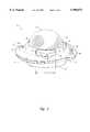
- FIG. 1is a front isometric view of a pointing device provided in accordance with a preferred embodiment of the present invention.
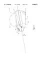
- FIG. 2is a right side elevational view of the pointing device of FIG. 1.
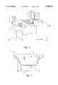
- FIG. 3is a bottom plan view of the pointing device of FIG. 1.
- FIG. 4is a top plan view of the pointing device of FIG. 1.
- FIG. 5is an illustration of the pointing device of FIG. 1 in use.
- FIG. 6is an exploded isometric view of the pointing device of FIG. 1.
- FIG. 7is a cross-sectional front elevational view of the pointing device of FIG. 1.
- a trackball-type pointing device 10provided in accordance with a preferred embodiment of the present invention is ergonomically designed, and in a preferred embodiment, is particularly well suited for young children, aged 2-6.
- the housing 12is substantially elliptical, the size and rounded edges of the housing 12 making it suitable for a user to position and use the pointing device 10 in his or her lap.
- a diameter 39 of a bottom surface 46is 3.75-6.25 inches, which corresponds to the range of interthigh crest dimensions expected for a 5th percentile 2-year old.
- diameter 41 of pointing device 10is 3.75-6.25 inches, the particular dimensions of the bottom region of pointing device 10 being selected according to the targeted age group.
- diameter 39is approximately 4 inches and diameter 41 is approximately 5 inches such that the pointing device is sized to be securely and comfortably held on the lap of a seated child aged 2-6.
- the pointing devicemay be positioned on a work surface, such as a table or desktop.
- a plurality of non-skid feet 45are provided on the bottom surface 46 of housing 12, as illustrated in FIG. 3.
- the housing 12is also symmetrical to allow the pointing device 10 to be grasped and used by either or both hands of a user.
- the housing 12has a first gripping area or handle 18 for a left hand of a user, and a second gripping area or handle 20 for a right hand of the user.
- a top surface 17 of each of gripping areas 18 and 20is provided with texture, for example, raised ridges 22, to provide a tactile and visual cue for the placement of the user's hands, and to enhance secure contact between the pointing device 10 and the user's hands.
- the housing 12slopes in upward direction from a front region 26 of the housing to a rear region 42, the positive slope being preferred to orient the product to the user.
- Orientationis believed to be important to ensure that the directional movement of the ball corresponds to the expected movement of the cursor 13 on a screen 11, such as of a computer 9.
- rolling the ball 14 "upwards” as illustrated by reference arrow 15should produce a corresponding movement of the cursor 13 upwards on the screen 11.
- rolling the ball 14 "downwards” as illustrated by reference arrow 19should cause the cursor 13 to move downward on the screen 11. It is therefore important to provide a visual cue to the user to orient the device with the front region 26 of the housing closest to the user.
- the slope 44 of housing 12is in the range of 5°-15°, to ensure that the slope is clearly discernible to a child aged 2-6 yet not require a movement beyond the comfortable range of motion for the child's hand when moving the hand from the front region 26 to the rear region 42 of pointing device 10. It is believed that optimal results are achieved when the slope 44 is 9°-11°.
- a relatively large ball 14is provided in housing 12, a portion of the ball 14 extending upward from an upper surface 16 of housing 12.
- the ball 14is sized to optimize manipulation of the ball by users having a hand length falling within an anthropometrically defined range, from a 5th percentile North American 2 year old to a 95th percentile North American 6 year old.
- the rangeis based on hand size, a larger percentage being assigned to a larger hand, and vice versa.
- This means that the ergonomic pointing device described hereinis believed to accommodate a group of users ranging from a 2 year old child in the fifth percentile, having a relatively small hand, to a 6 year old child in the ninety-fifth percentile, having a relative large hand. It will be appreciated that users falling outside of this design range may still enjoy advantages from the preferred embodiment and that alternative preferred embodiments can be developed for other target user groups, for example, 7-10 year olds, in accordance with the present invention.
- the diameter of the ballis 3.38-6.7 inches. It is believed that optimal results are achieved when a diameter of the ball is 3.75-4.5 inches, and in particular 4 inches.
- the ballmay be controlled by a left hand or right hand or even both hands of a user.
- the ball 14thereby accommodates the motor skills of children aged 2-6, given that the relatively large contact area allows the user to control the ball with larger movements that use more muscles and are therefore relatively easy to make when compared to the ease with which children aged 2-6 may make fine, precise, and smaller movements.
- ball 1 having a diameter of 3.0 incheswas too small for all of the users that the observers were able to review and assign a rating.
- ball 2 having a diameter of 5.0 inches and ball 3 having a diameter of 4.75 incheswere both too big.
- the housingis configured to capture over 1/2 of the surface area of the ball. This prevents users, particularly children, from easily removing the ball, and from placing their hands or other objects into the pointing device.
- the tolerance or gap 47 between the twois 0.5 mm ⁇ 0.3 mm as illustrated in FIGS. 1 and 4, and a lip 50 is provided around opening 48 in which ball 14 sits. This close tolerance further minimizes the amount of dust and debris that may enter housing 12 via gap 47, thereby improving the length of time the pointing device may be accurately operated without needing to open the housing and clean an inner region of the pointing device.
- lip 50is polished to further ensure that dust or other debris slides away from gap 47.
- a printed circuit board (PCB) 23 contained in housing 12is protected by being encased by a cover having a top bracket 21 and a bottom bracket 27 that screw together to form an encoder chassis assembly. Therefore, when it is desired to clean encoder wheels 29 and an inner bottom region 37 of housing 12, four screws 35 are removed and a top half 31 of housing 12 is removed from a bottom half 33 of housing 12. Ball 14 may also then be removed, exposing inner region 37. Encoder wheels 29 are also accessible for cleaning through a gap between bracket 21 and bracket 27; however, printed circuit board 23 is encased in brackets 21 and 27.
- the ease with which the ball may be rotated by a useris set to provide sufficient resistance to accommodate the motor skills of children aged 2-6, thereby ensuring that a child user will have adequate control over the movement of the ball to accurately position the cursor.
- a button 24is provided in a front region 26 of housing 12, the button location, size, and shape being configured to optimize a target area and activation of the button 24.
- placement of the button in a front region 26 of housing 12is preferred given that in typical postures during use, both on the lap of a user and on a work surface, movement of the hand from the ball 14 to the button 24 requires a movement of the forearm more within the neutral range of movement, as opposed to a movement from the ball 14 to a rear region 42 of the housing, which requires an extension of the forearm.
- the placement of the button 24 in the front region of the pointing deviceis in keeping with stereotypical behavior and expectancies for children aged 2-6.
- the front location of the button 24is also equally accessible to both left- and right-handed use of the pointing device 10.
- the button 24is shaped in an elongated oval, curving concentrically with the ball 14.
- Button 24has a length 28 of 1.75-2.5 inches, a width 30 of 0.5-0.75 inch, and comprises approximately 40°-60° of arc 32.
- This button size and shapeoptimizes the target area and activation of the button 24, given that the elongated oval accommodates activation within a range of angles expected when either the left or right hand, index finger or thumb, is moved from the top of the ball 14 to the front region 26 of the device, without interfering with the gripping areas 18 and 20 to either side of the button.
- the arc 32 of the buttonis too large, the button 24 will interfere with gripping areas 18 and 20, and if arc 22 is too small, the button presents a target that requires more precise alignment of hand movement than is optimal for children aged 2-6.
- a first end 34 and second end 36 of button 24are fully radiused for comfortable, safe contact, and to present a larger and less directional activation area to the user.
- a front edge 38 of button 24is raised to ensure that the button will activate a switch 25 in the pointing device, no matter where on its surface the button is depressed.
- a usergrasps the pointing device 10 via gripping areas 18 and 20, and positions the pointing device with the front region 26 nearest to the user.
- the pointing device 10may be placed on a work surface or on the user's lap.
- a userplaces a hand on the ball 14, and rotates the ball to cause a desired corresponding movement of the cursor 13 on the monitor 11.
- the userstrikes the button 24 with a thumb or finger of the user's hand, thereby entering a command into the computer 9.
Landscapes
- Engineering & Computer Science (AREA)
- General Engineering & Computer Science (AREA)
- Theoretical Computer Science (AREA)
- Human Computer Interaction (AREA)
- Physics & Mathematics (AREA)
- General Physics & Mathematics (AREA)
- Position Input By Displaying (AREA)
Abstract
Description
TABLE 1 ______________________________________ Frequency Count Too Too Ball Size Small Big OK Good Overall Ball # (inches) (-1) (-1) (.5) (+1) N/A Rating ______________________________________ 1 3.0 8 -- -- -- 1 too small 2 5.0 -- 6 -- -- 3 too big 3 4.75 -- 4 2 1 1 -2 = too big 4 4.5 -- 1 7 -- 1 2.5 = ok 5 4 -- -- 4 3 2 5 = good 6 3.5 2 -- 3 1 3 .5 = ok ______________________________________
Claims (17)
Priority Applications (2)
| Application Number | Priority Date | Filing Date | Title |
|---|---|---|---|
| TW084103561ATW288131B (en) | 1995-04-12 | 1995-04-12 | Ergonomic pointing device |
| US08/422,484US5990871A (en) | 1995-04-12 | 1995-04-12 | Ergonomic pointing device |
Applications Claiming Priority (1)
| Application Number | Priority Date | Filing Date | Title |
|---|---|---|---|
| US08/422,484US5990871A (en) | 1995-04-12 | 1995-04-12 | Ergonomic pointing device |
Publications (1)
| Publication Number | Publication Date |
|---|---|
| US5990871Atrue US5990871A (en) | 1999-11-23 |
Family
ID=23675092
Family Applications (1)
| Application Number | Title | Priority Date | Filing Date |
|---|---|---|---|
| US08/422,484Expired - LifetimeUS5990871A (en) | 1995-04-12 | 1995-04-12 | Ergonomic pointing device |
Country Status (2)
| Country | Link |
|---|---|
| US (1) | US5990871A (en) |
| TW (1) | TW288131B (en) |
Cited By (10)
| Publication number | Priority date | Publication date | Assignee | Title |
|---|---|---|---|---|
| USD480400S1 (en) | 2002-07-09 | 2003-10-07 | Active Release Techniques Llc | Ergonomic electronic input device |
| US20040017272A1 (en)* | 2002-02-19 | 2004-01-29 | Smith Stephanie L. | Low cost dielectric tuning for E-plane filters |
| US6724366B2 (en)* | 2001-04-03 | 2004-04-20 | Peter James Crawford | Thumb actuated x-y input device |
| FR2860675A1 (en)* | 2003-10-03 | 2005-04-08 | Marie Madeleine Renee Bernard | Interactive communication providing process for telecommunication application, involves pushing share button by remote user for local user to remotely view document field identical with time |
| US6922700B1 (en)* | 2000-05-16 | 2005-07-26 | International Business Machines Corporation | System and method for similarity indexing and searching in high dimensional space |
| US6922186B2 (en) | 2001-03-15 | 2005-07-26 | Curtis Whitcomb | Ergonomic computer mouse |
| US6921054B2 (en)* | 2002-06-12 | 2005-07-26 | Jimmy-Quang V. Doan | Ergonomic mouse |
| US20060250364A1 (en)* | 2005-05-09 | 2006-11-09 | Alex Gorbunov | Ergonomic computer mouse |
| US20070284809A1 (en)* | 2003-02-27 | 2007-12-13 | Canon Kabushiki Kaisha | Sheet handling apparatus and image forming apparatus |
| US8314772B1 (en) | 2009-08-28 | 2012-11-20 | Coe Stanley S | Computer mouse |
Citations (34)
| Publication number | Priority date | Publication date | Assignee | Title |
|---|---|---|---|---|
| US3395589A (en)* | 1966-06-06 | 1968-08-06 | Orbit Instr Corp | Motion converting apparatus |
| US3625083A (en)* | 1969-10-17 | 1971-12-07 | Singer Co | Track ball encoder |
| US4404865A (en)* | 1982-02-10 | 1983-09-20 | Wico Corporation | Trackball device |
| USD272921S (en) | 1982-02-04 | 1984-03-06 | Wico Corporation | Control for a video game or the like |
| US4533830A (en)* | 1982-12-16 | 1985-08-06 | Disc Instruments, Inc. | Optical encoder with a shutter clutched for directional movement |
| US4538476A (en)* | 1983-05-12 | 1985-09-03 | Luque Tom R | Cursor control assembly |
| GB2154306A (en)* | 1984-02-16 | 1985-09-04 | Depraz S A | "X-Y" Input device |
| USD281776S (en) | 1983-11-21 | 1985-12-17 | Illinois Tool Works Inc. | Remote control hemisphere switch |
| US4562347A (en)* | 1983-09-23 | 1985-12-31 | Trace Systems, Inc. | Input device featuring both trackball and mouse capability |
| US4581609A (en)* | 1983-02-28 | 1986-04-08 | Alps Electric Co., Ltd. | X-Y position input device for display system |
| USD291318S (en) | 1985-01-14 | 1987-08-11 | Wico Distribution Company, L.P. | Combined trackball and mouse |
| USD292600S (en) | 1984-04-09 | 1987-11-03 | Asea Aktiebolag | Track ball unit |
| US4786892A (en)* | 1986-02-22 | 1988-11-22 | Alps Electric Co., Ltd. | X-Y direction input device having changeable orientation of input axes and switch activation |
| USD299140S (en) | 1985-05-24 | 1988-12-27 | Hal Laboratory, Inc. | Cursor control for computer display |
| US4799049A (en)* | 1985-01-25 | 1989-01-17 | Avila Harold C | Image position control |
| US4801931A (en)* | 1986-10-25 | 1989-01-31 | Hewlett-Packard Company | Device for controlling the motion of a video-screen cursor |
| US4823634A (en)* | 1987-11-03 | 1989-04-25 | Culver Craig F | Multifunction tactile manipulatable control |
| USD302010S (en) | 1986-07-21 | 1989-07-04 | Itac Systems, Inc. | Computer cursor control |
| US4913387A (en)* | 1989-03-17 | 1990-04-03 | Hewlett-Packard Company | Apparatus for removably mounting a computer input device |
| US4952919A (en)* | 1989-04-06 | 1990-08-28 | Tektronix, Inc. | Trackball mechanism |
| USD315552S (en) | 1989-12-22 | 1991-03-19 | Curtis Manufacturing Company, Inc. | Trackball for a computer |
| US5008528A (en)* | 1989-07-14 | 1991-04-16 | Logitech S.A. | Invertible trackball |
| USD326261S (en) | 1991-03-08 | 1992-05-19 | Microsoft Corporation | Trackball for computer |
| US5122654A (en)* | 1990-05-25 | 1992-06-16 | Logitech, Inc. | Ergonomic thumb-actuated trackball combined with control switches |
| EP0509337A2 (en)* | 1991-04-05 | 1992-10-21 | Logitech Inc | Track ball mounted on keyboard |
| US5187468A (en)* | 1989-10-23 | 1993-02-16 | Microsoft Corporation | Pointing device with adjustable clamp attachable to a keyboard |
| USD335656S (en) | 1990-12-27 | 1993-05-18 | Microsoft Corporation | Pointed instrument with a combined tilting and coupling assembly |
| US5252970A (en)* | 1991-01-30 | 1993-10-12 | David Baronowsky | Ergonomic multi-axis controller |
| US5268675A (en)* | 1989-10-23 | 1993-12-07 | Microsoft Corporation | Computer command and pointing device with multi-axis engagement assembly |
| US5281958A (en)* | 1989-10-23 | 1994-01-25 | Microsoft Corporation | Pointing device with adjustable clamp attachable to a keyboard |
| USD347628S (en) | 1992-12-23 | 1994-06-07 | Microsoft Corporation | Computer trackball |
| US5334997A (en)* | 1992-12-22 | 1994-08-02 | David Scallon | Foot-operated computer control |
| US5340067A (en)* | 1992-03-27 | 1994-08-23 | Martin Teresa A | Hand and wrist support for computer mouse |
| USD350344S (en) | 1992-10-13 | 1994-09-06 | International Business Machines Corporation | Computer pointing device |
- 1995
- 1995-04-12USUS08/422,484patent/US5990871A/ennot_activeExpired - Lifetime
- 1995-04-12TWTW084103561Apatent/TW288131B/enactive
Patent Citations (34)
| Publication number | Priority date | Publication date | Assignee | Title |
|---|---|---|---|---|
| US3395589A (en)* | 1966-06-06 | 1968-08-06 | Orbit Instr Corp | Motion converting apparatus |
| US3625083A (en)* | 1969-10-17 | 1971-12-07 | Singer Co | Track ball encoder |
| USD272921S (en) | 1982-02-04 | 1984-03-06 | Wico Corporation | Control for a video game or the like |
| US4404865A (en)* | 1982-02-10 | 1983-09-20 | Wico Corporation | Trackball device |
| US4533830A (en)* | 1982-12-16 | 1985-08-06 | Disc Instruments, Inc. | Optical encoder with a shutter clutched for directional movement |
| US4581609A (en)* | 1983-02-28 | 1986-04-08 | Alps Electric Co., Ltd. | X-Y position input device for display system |
| US4538476A (en)* | 1983-05-12 | 1985-09-03 | Luque Tom R | Cursor control assembly |
| US4562347A (en)* | 1983-09-23 | 1985-12-31 | Trace Systems, Inc. | Input device featuring both trackball and mouse capability |
| USD281776S (en) | 1983-11-21 | 1985-12-17 | Illinois Tool Works Inc. | Remote control hemisphere switch |
| GB2154306A (en)* | 1984-02-16 | 1985-09-04 | Depraz S A | "X-Y" Input device |
| USD292600S (en) | 1984-04-09 | 1987-11-03 | Asea Aktiebolag | Track ball unit |
| USD291318S (en) | 1985-01-14 | 1987-08-11 | Wico Distribution Company, L.P. | Combined trackball and mouse |
| US4799049A (en)* | 1985-01-25 | 1989-01-17 | Avila Harold C | Image position control |
| USD299140S (en) | 1985-05-24 | 1988-12-27 | Hal Laboratory, Inc. | Cursor control for computer display |
| US4786892A (en)* | 1986-02-22 | 1988-11-22 | Alps Electric Co., Ltd. | X-Y direction input device having changeable orientation of input axes and switch activation |
| USD302010S (en) | 1986-07-21 | 1989-07-04 | Itac Systems, Inc. | Computer cursor control |
| US4801931A (en)* | 1986-10-25 | 1989-01-31 | Hewlett-Packard Company | Device for controlling the motion of a video-screen cursor |
| US4823634A (en)* | 1987-11-03 | 1989-04-25 | Culver Craig F | Multifunction tactile manipulatable control |
| US4913387A (en)* | 1989-03-17 | 1990-04-03 | Hewlett-Packard Company | Apparatus for removably mounting a computer input device |
| US4952919A (en)* | 1989-04-06 | 1990-08-28 | Tektronix, Inc. | Trackball mechanism |
| US5008528A (en)* | 1989-07-14 | 1991-04-16 | Logitech S.A. | Invertible trackball |
| US5268675A (en)* | 1989-10-23 | 1993-12-07 | Microsoft Corporation | Computer command and pointing device with multi-axis engagement assembly |
| US5281958A (en)* | 1989-10-23 | 1994-01-25 | Microsoft Corporation | Pointing device with adjustable clamp attachable to a keyboard |
| US5187468A (en)* | 1989-10-23 | 1993-02-16 | Microsoft Corporation | Pointing device with adjustable clamp attachable to a keyboard |
| USD315552S (en) | 1989-12-22 | 1991-03-19 | Curtis Manufacturing Company, Inc. | Trackball for a computer |
| US5122654A (en)* | 1990-05-25 | 1992-06-16 | Logitech, Inc. | Ergonomic thumb-actuated trackball combined with control switches |
| USD335656S (en) | 1990-12-27 | 1993-05-18 | Microsoft Corporation | Pointed instrument with a combined tilting and coupling assembly |
| US5252970A (en)* | 1991-01-30 | 1993-10-12 | David Baronowsky | Ergonomic multi-axis controller |
| USD326261S (en) | 1991-03-08 | 1992-05-19 | Microsoft Corporation | Trackball for computer |
| EP0509337A2 (en)* | 1991-04-05 | 1992-10-21 | Logitech Inc | Track ball mounted on keyboard |
| US5340067A (en)* | 1992-03-27 | 1994-08-23 | Martin Teresa A | Hand and wrist support for computer mouse |
| USD350344S (en) | 1992-10-13 | 1994-09-06 | International Business Machines Corporation | Computer pointing device |
| US5334997A (en)* | 1992-12-22 | 1994-08-02 | David Scallon | Foot-operated computer control |
| USD347628S (en) | 1992-12-23 | 1994-06-07 | Microsoft Corporation | Computer trackball |
Non-Patent Citations (7)
| Title |
|---|
| Formative studies in the development of a new computer pointing device for young children Erik F. Strommen, Educational Technology/Apr. 1992.* |
| Krohn, Nico, "Two Prohance Trackballs Offer Easy Thumb Control," Infoworld, Oct. 1, 1990. |
| Krohn, Nico, Two Prohance Trackballs Offer Easy Thumb Control, Infoworld , Oct. 1, 1990.* |
| Lusty, Susan and Lincoln Spector, "Keyboards, Mice, and Trackballs With the Personal Touch," PC World, Jum. 1990. |
| Lusty, Susan and Lincoln Spector, Keyboards, Mice, and Trackballs With the Personal Touch, PC World , Jum. 1990.* |
| Webster, Bruce F., "The Macintosh Portable," MACWORLD, Nov. 1989. |
| Webster, Bruce F., The Macintosh Portable, MACWORLD , Nov. 1989.* |
Cited By (11)
| Publication number | Priority date | Publication date | Assignee | Title |
|---|---|---|---|---|
| US6922700B1 (en)* | 2000-05-16 | 2005-07-26 | International Business Machines Corporation | System and method for similarity indexing and searching in high dimensional space |
| US6922186B2 (en) | 2001-03-15 | 2005-07-26 | Curtis Whitcomb | Ergonomic computer mouse |
| US6724366B2 (en)* | 2001-04-03 | 2004-04-20 | Peter James Crawford | Thumb actuated x-y input device |
| USRE40324E1 (en)* | 2001-04-03 | 2008-05-20 | Dhol New Ventures, Llc | Thumb actuated X-Y input device |
| US20040017272A1 (en)* | 2002-02-19 | 2004-01-29 | Smith Stephanie L. | Low cost dielectric tuning for E-plane filters |
| US6921054B2 (en)* | 2002-06-12 | 2005-07-26 | Jimmy-Quang V. Doan | Ergonomic mouse |
| USD480400S1 (en) | 2002-07-09 | 2003-10-07 | Active Release Techniques Llc | Ergonomic electronic input device |
| US20070284809A1 (en)* | 2003-02-27 | 2007-12-13 | Canon Kabushiki Kaisha | Sheet handling apparatus and image forming apparatus |
| FR2860675A1 (en)* | 2003-10-03 | 2005-04-08 | Marie Madeleine Renee Bernard | Interactive communication providing process for telecommunication application, involves pushing share button by remote user for local user to remotely view document field identical with time |
| US20060250364A1 (en)* | 2005-05-09 | 2006-11-09 | Alex Gorbunov | Ergonomic computer mouse |
| US8314772B1 (en) | 2009-08-28 | 2012-11-20 | Coe Stanley S | Computer mouse |
Also Published As
| Publication number | Publication date |
|---|---|
| TW288131B (en) | 1996-10-11 |
Similar Documents
| Publication | Publication Date | Title |
|---|---|---|
| US5414445A (en) | Ergonomic pointing device | |
| US5563628A (en) | Hand held computer cursor controller and command input device | |
| US5894303A (en) | Computer mouse and shell therefore | |
| US6181322B1 (en) | Pointing device having selection buttons operable from movement of a palm portion of a person's hands | |
| US7277083B2 (en) | Ergonomically designed computer gaming device | |
| US6922186B2 (en) | Ergonomic computer mouse | |
| US6323843B2 (en) | Computer mouse | |
| KR100645857B1 (en) | Dual axis articulated computer input device and method of operation | |
| US20050052412A1 (en) | Hand manipulated data apparatus for computers and video games | |
| US4650934A (en) | Hand movement controller | |
| US5990871A (en) | Ergonomic pointing device | |
| US20060001646A1 (en) | Finger worn and operated input device | |
| US6104383A (en) | Thumb-actuated computer pointing-input device | |
| US7006075B1 (en) | Ergonomic computer mouse | |
| US6275215B1 (en) | Mouse having buttons which can be operated both vertically and horizontally | |
| US6031523A (en) | Meta-rest improved PC mouse | |
| US7286114B2 (en) | Track ball structure | |
| US8614677B2 (en) | Mouse with adjustable switch | |
| US20080106441A1 (en) | Keyboard in the form of a carpet or a mat | |
| WO2002001589A1 (en) | A user input device for a game simulation apparatus | |
| JP3148760B2 (en) | Input device | |
| AU2002234245B2 (en) | Computer mouse | |
| WO2003010648A1 (en) | A pointing device | |
| CA1241090A (en) | Hand movement controller | |
| KR200262391Y1 (en) | Ergonomic computer mouse |
Legal Events
| Date | Code | Title | Description |
|---|---|---|---|
| AS | Assignment | Owner name:MICROSOFT CORPORATION, WASHINGTON Free format text:ASSIGNMENT OF ASSIGNORS INTEREST;ASSIGNORS:ADAMS, ADITHA MAY;KANEKO, STEVEN T.;VAN ENGELEN, FERDINAND;AND OTHERS;REEL/FRAME:007518/0405;SIGNING DATES FROM 19950407 TO 19950604 | |
| STCF | Information on status: patent grant | Free format text:PATENTED CASE | |
| FPAY | Fee payment | Year of fee payment:4 | |
| FPAY | Fee payment | Year of fee payment:8 | |
| FPAY | Fee payment | Year of fee payment:12 | |
| AS | Assignment | Owner name:MICROSOFT TECHNOLOGY LICENSING, LLC, WASHINGTON Free format text:ASSIGNMENT OF ASSIGNORS INTEREST;ASSIGNOR:MICROSOFT CORPORATION;REEL/FRAME:034541/0001 Effective date:20141014 | |
| AS | Assignment | Owner name:MICROSOFT CORPORATION, WASHINGTON Free format text:ASSIGNMENT OF ASSIGNORS INTEREST;ASSIGNOR:MICROSOFT TECHNOLOGY LICENSING, LLC;REEL/FRAME:036930/0248 Effective date:20150128 | |
| AS | Assignment | Owner name:MICROSOFT TECHNOLOGY LICENSING, LLC, WASHINGTON Free format text:ASSIGNMENT OF ASSIGNORS INTEREST;ASSIGNOR:MICROSOFT CORPORATION;REEL/FRAME:041517/0431 Effective date:20170123 | |
| AS | Assignment | Owner name:MICROSOFT TECHNOLOGY LICENSING, LLC, WASHINGTON Free format text:CORRECTIVE ASSIGNMENT TO CORRECT THE PATENT NUMBER 6030518 PREVIOUSLY RECORDED ON REEL 041517 FRAME 0431. ASSIGNOR(S) HEREBY CONFIRMS THE ASSIGNMENT;ASSIGNOR:MICROSOFT CORPORATION;REEL/FRAME:042334/0251 Effective date:20170123 |