US5990582A - Computer fan speed control device - Google Patents
Computer fan speed control deviceDownload PDFInfo
- Publication number
- US5990582A US5990582AUS08/942,447US94244797AUS5990582AUS 5990582 AUS5990582 AUS 5990582AUS 94244797 AUS94244797 AUS 94244797AUS 5990582 AUS5990582 AUS 5990582A
- Authority
- US
- United States
- Prior art keywords
- fan
- voltage
- input
- speed
- switch
- Prior art date
- Legal status (The legal status is an assumption and is not a legal conclusion. Google has not performed a legal analysis and makes no representation as to the accuracy of the status listed.)
- Expired - Lifetime
Links
Images


Classifications
- G—PHYSICS
- G06—COMPUTING OR CALCULATING; COUNTING
- G06F—ELECTRIC DIGITAL DATA PROCESSING
- G06F9/00—Arrangements for program control, e.g. control units
- G06F9/06—Arrangements for program control, e.g. control units using stored programs, i.e. using an internal store of processing equipment to receive or retain programs
- G06F9/44—Arrangements for executing specific programs
- G06F9/4401—Bootstrapping
- G06F9/4411—Configuring for operating with peripheral devices; Loading of device drivers
- F—MECHANICAL ENGINEERING; LIGHTING; HEATING; WEAPONS; BLASTING
- F04—POSITIVE - DISPLACEMENT MACHINES FOR LIQUIDS; PUMPS FOR LIQUIDS OR ELASTIC FLUIDS
- F04D—NON-POSITIVE-DISPLACEMENT PUMPS
- F04D29/00—Details, component parts, or accessories
- F04D29/60—Mounting; Assembling; Disassembling
- F04D29/601—Mounting; Assembling; Disassembling specially adapted for elastic fluid pumps
- G—PHYSICS
- G06—COMPUTING OR CALCULATING; COUNTING
- G06F—ELECTRIC DIGITAL DATA PROCESSING
- G06F11/00—Error detection; Error correction; Monitoring
- G06F11/07—Responding to the occurrence of a fault, e.g. fault tolerance
- G06F11/0703—Error or fault processing not based on redundancy, i.e. by taking additional measures to deal with the error or fault not making use of redundancy in operation, in hardware, or in data representation
- G06F11/0706—Error or fault processing not based on redundancy, i.e. by taking additional measures to deal with the error or fault not making use of redundancy in operation, in hardware, or in data representation the processing taking place on a specific hardware platform or in a specific software environment
- G06F11/0748—Error or fault processing not based on redundancy, i.e. by taking additional measures to deal with the error or fault not making use of redundancy in operation, in hardware, or in data representation the processing taking place on a specific hardware platform or in a specific software environment in a remote unit communicating with a single-box computer node experiencing an error/fault
- G—PHYSICS
- G06—COMPUTING OR CALCULATING; COUNTING
- G06F—ELECTRIC DIGITAL DATA PROCESSING
- G06F11/00—Error detection; Error correction; Monitoring
- G06F11/07—Responding to the occurrence of a fault, e.g. fault tolerance
- G06F11/0703—Error or fault processing not based on redundancy, i.e. by taking additional measures to deal with the error or fault not making use of redundancy in operation, in hardware, or in data representation
- G06F11/0766—Error or fault reporting or storing
- G06F11/0772—Means for error signaling, e.g. using interrupts, exception flags, dedicated error registers
- G—PHYSICS
- G06—COMPUTING OR CALCULATING; COUNTING
- G06F—ELECTRIC DIGITAL DATA PROCESSING
- G06F11/00—Error detection; Error correction; Monitoring
- G06F11/22—Detection or location of defective computer hardware by testing during standby operation or during idle time, e.g. start-up testing
- G06F11/2294—Detection or location of defective computer hardware by testing during standby operation or during idle time, e.g. start-up testing by remote test
- G—PHYSICS
- G06—COMPUTING OR CALCULATING; COUNTING
- G06F—ELECTRIC DIGITAL DATA PROCESSING
- G06F11/00—Error detection; Error correction; Monitoring
- G06F11/30—Monitoring
- G06F11/32—Monitoring with visual or acoustical indication of the functioning of the machine
- G06F11/324—Display of status information
- G06F11/328—Computer systems status display
- G—PHYSICS
- G06—COMPUTING OR CALCULATING; COUNTING
- G06F—ELECTRIC DIGITAL DATA PROCESSING
- G06F11/00—Error detection; Error correction; Monitoring
- G06F11/30—Monitoring
- G06F11/34—Recording or statistical evaluation of computer activity, e.g. of down time, of input/output operation ; Recording or statistical evaluation of user activity, e.g. usability assessment
- G06F11/3466—Performance evaluation by tracing or monitoring
- G—PHYSICS
- G06—COMPUTING OR CALCULATING; COUNTING
- G06F—ELECTRIC DIGITAL DATA PROCESSING
- G06F13/00—Interconnection of, or transfer of information or other signals between, memories, input/output devices or central processing units
- G06F13/38—Information transfer, e.g. on bus
- G06F13/40—Bus structure
- G06F13/4004—Coupling between buses
- G06F13/4027—Coupling between buses using bus bridges
- G—PHYSICS
- G06—COMPUTING OR CALCULATING; COUNTING
- G06F—ELECTRIC DIGITAL DATA PROCESSING
- G06F13/00—Interconnection of, or transfer of information or other signals between, memories, input/output devices or central processing units
- G06F13/38—Information transfer, e.g. on bus
- G06F13/40—Bus structure
- G06F13/4063—Device-to-bus coupling
- G06F13/4068—Electrical coupling
- G06F13/4081—Live connection to bus, e.g. hot-plugging
- G—PHYSICS
- G06—COMPUTING OR CALCULATING; COUNTING
- G06F—ELECTRIC DIGITAL DATA PROCESSING
- G06F21/00—Security arrangements for protecting computers, components thereof, programs or data against unauthorised activity
- G06F21/30—Authentication, i.e. establishing the identity or authorisation of security principals
- G06F21/305—Authentication, i.e. establishing the identity or authorisation of security principals by remotely controlling device operation
- G—PHYSICS
- G06—COMPUTING OR CALCULATING; COUNTING
- G06F—ELECTRIC DIGITAL DATA PROCESSING
- G06F21/00—Security arrangements for protecting computers, components thereof, programs or data against unauthorised activity
- G06F21/30—Authentication, i.e. establishing the identity or authorisation of security principals
- G06F21/31—User authentication
- H—ELECTRICITY
- H04—ELECTRIC COMMUNICATION TECHNIQUE
- H04L—TRANSMISSION OF DIGITAL INFORMATION, e.g. TELEGRAPHIC COMMUNICATION
- H04L12/00—Data switching networks
- H04L12/02—Details
- H04L12/12—Arrangements for remote connection or disconnection of substations or of equipment thereof
- H—ELECTRICITY
- H04—ELECTRIC COMMUNICATION TECHNIQUE
- H04L—TRANSMISSION OF DIGITAL INFORMATION, e.g. TELEGRAPHIC COMMUNICATION
- H04L41/00—Arrangements for maintenance, administration or management of data switching networks, e.g. of packet switching networks
- H04L41/12—Discovery or management of network topologies
- H—ELECTRICITY
- H04—ELECTRIC COMMUNICATION TECHNIQUE
- H04L—TRANSMISSION OF DIGITAL INFORMATION, e.g. TELEGRAPHIC COMMUNICATION
- H04L41/00—Arrangements for maintenance, administration or management of data switching networks, e.g. of packet switching networks
- H04L41/22—Arrangements for maintenance, administration or management of data switching networks, e.g. of packet switching networks comprising specially adapted graphical user interfaces [GUI]
- H—ELECTRICITY
- H04—ELECTRIC COMMUNICATION TECHNIQUE
- H04L—TRANSMISSION OF DIGITAL INFORMATION, e.g. TELEGRAPHIC COMMUNICATION
- H04L49/00—Packet switching elements
- H04L49/90—Buffering arrangements
- H—ELECTRICITY
- H04—ELECTRIC COMMUNICATION TECHNIQUE
- H04L—TRANSMISSION OF DIGITAL INFORMATION, e.g. TELEGRAPHIC COMMUNICATION
- H04L67/00—Network arrangements or protocols for supporting network services or applications
- H04L67/01—Protocols
- H04L67/10—Protocols in which an application is distributed across nodes in the network
- H04L67/1001—Protocols in which an application is distributed across nodes in the network for accessing one among a plurality of replicated servers
- G—PHYSICS
- G06—COMPUTING OR CALCULATING; COUNTING
- G06F—ELECTRIC DIGITAL DATA PROCESSING
- G06F11/00—Error detection; Error correction; Monitoring
- G06F11/07—Responding to the occurrence of a fault, e.g. fault tolerance
- G06F11/0703—Error or fault processing not based on redundancy, i.e. by taking additional measures to deal with the error or fault not making use of redundancy in operation, in hardware, or in data representation
- G06F11/0793—Remedial or corrective actions
- G—PHYSICS
- G06—COMPUTING OR CALCULATING; COUNTING
- G06F—ELECTRIC DIGITAL DATA PROCESSING
- G06F11/00—Error detection; Error correction; Monitoring
- G06F11/30—Monitoring
- G06F11/3058—Monitoring arrangements for monitoring environmental properties or parameters of the computing system or of the computing system component, e.g. monitoring of power, currents, temperature, humidity, position, vibrations
- G—PHYSICS
- G06—COMPUTING OR CALCULATING; COUNTING
- G06F—ELECTRIC DIGITAL DATA PROCESSING
- G06F11/00—Error detection; Error correction; Monitoring
- G06F11/30—Monitoring
- G06F11/34—Recording or statistical evaluation of computer activity, e.g. of down time, of input/output operation ; Recording or statistical evaluation of user activity, e.g. usability assessment
- G06F11/3466—Performance evaluation by tracing or monitoring
- G06F11/3476—Data logging
- G—PHYSICS
- G06—COMPUTING OR CALCULATING; COUNTING
- G06F—ELECTRIC DIGITAL DATA PROCESSING
- G06F11/00—Error detection; Error correction; Monitoring
- G06F11/30—Monitoring
- G06F11/34—Recording or statistical evaluation of computer activity, e.g. of down time, of input/output operation ; Recording or statistical evaluation of user activity, e.g. usability assessment
- G06F11/3466—Performance evaluation by tracing or monitoring
- G06F11/3495—Performance evaluation by tracing or monitoring for systems
- G—PHYSICS
- G06—COMPUTING OR CALCULATING; COUNTING
- G06F—ELECTRIC DIGITAL DATA PROCESSING
- G06F2201/00—Indexing scheme relating to error detection, to error correction, and to monitoring
- G06F2201/86—Event-based monitoring
- G—PHYSICS
- G06—COMPUTING OR CALCULATING; COUNTING
- G06F—ELECTRIC DIGITAL DATA PROCESSING
- G06F3/00—Input arrangements for transferring data to be processed into a form capable of being handled by the computer; Output arrangements for transferring data from processing unit to output unit, e.g. interface arrangements
- G06F3/06—Digital input from, or digital output to, record carriers, e.g. RAID, emulated record carriers or networked record carriers
- G06F3/0601—Interfaces specially adapted for storage systems
- G06F3/0668—Interfaces specially adapted for storage systems adopting a particular infrastructure
- G06F3/0671—In-line storage system
- G06F3/0673—Single storage device
- H—ELECTRICITY
- H04—ELECTRIC COMMUNICATION TECHNIQUE
- H04L—TRANSMISSION OF DIGITAL INFORMATION, e.g. TELEGRAPHIC COMMUNICATION
- H04L41/00—Arrangements for maintenance, administration or management of data switching networks, e.g. of packet switching networks
- H04L41/02—Standardisation; Integration
- H04L41/0213—Standardised network management protocols, e.g. simple network management protocol [SNMP]
- Y—GENERAL TAGGING OF NEW TECHNOLOGICAL DEVELOPMENTS; GENERAL TAGGING OF CROSS-SECTIONAL TECHNOLOGIES SPANNING OVER SEVERAL SECTIONS OF THE IPC; TECHNICAL SUBJECTS COVERED BY FORMER USPC CROSS-REFERENCE ART COLLECTIONS [XRACs] AND DIGESTS
- Y02—TECHNOLOGIES OR APPLICATIONS FOR MITIGATION OR ADAPTATION AGAINST CLIMATE CHANGE
- Y02D—CLIMATE CHANGE MITIGATION TECHNOLOGIES IN INFORMATION AND COMMUNICATION TECHNOLOGIES [ICT], I.E. INFORMATION AND COMMUNICATION TECHNOLOGIES AIMING AT THE REDUCTION OF THEIR OWN ENERGY USE
- Y02D30/00—Reducing energy consumption in communication networks
- Y02D30/50—Reducing energy consumption in communication networks in wire-line communication networks, e.g. low power modes or reduced link rate
Definitions
- Appendix Awhich forms a part of this disclosure, is a list of commonly owned copending U.S. patent applications. Each one of the applications listed in Appendix A is hereby incorporated herein in its entirety by reference thereto.
- the inventionrelates to computer equipment and, in particular, relates to a system and a method for sensing and controlling the speed of one or more cooling fans used to cool personal computers.
- heat sinksare often attached to heat generating electronic components, such as microprocessors, and fans are also used for forced air cooling of the electronic components. Specifically, fans are used to blow air over the heat generating electronic components and also to blow the accumulated hot air away from the atmosphere surrounding the components to thereby lower the air temperature and allow for more heat to be radiated out of the component.
- a plurality of fansare used to cool the chassis section of the personal computer.
- the number of fansis selected to provide a desired amount of forced air cooling with some redundancy.
- the redundancyis provided so that if one or more of the fans fail, adequate cooling can still be provided by the remaining fans. This redundancy, however, increases the overall cost of the computer as more fans are installed than are actually needed for normal cooling operations. Further, it will be appreciated that when all of the fans are operating, the fans are generating an increased amount of noise.
- multi-speed fansare currently available for use with personal computers, if one of these fans fail, the prior art personal computers are often unable to detect the failure and to take corrective action.
- multi-speed fanscan be used to provide varying cooling capacity within the personal computer chassis, these systems are not generally capable of accommodating a failure of one or more of the fans.
- the multi-speed fansare also generally selected so as to provide more cooling capacity than is actually required to account for the subsequent loss of one or more fans. This of course causes greater power drain on the power supply, results in noisier computers and also decreases the longevity of the fans themselves.
- One embodiment of the inventionincludes a cooling apparatus for a computer that comprises a first voltage source providing a first voltage, a reference voltage source providing a reference voltage, a fan having a first input and a second input which is adapted to be mounted in a computer so as to be able to blow air over components in the computer wherein the fan operates at a speed that is related to the voltage that is applied during the first and second inputs on the fan.
- This apparatusmay also include a voltage divider connected to the first voltage source and the positive input of the fan wherein the second input of the fan is connected to the reference voltage source.
- a switchmay be connected between the first input of the fan so that when the switch is in a first position, the fan receives a first input voltage that operates a first speed and when the switch is in a second position, the fan is connected to the first voltage source via the voltage divider such that the fan receives a second input voltage and operates a second speed wherein the second input voltage and the second speed have a lesser magnitude than the first input voltage and the first speed.
- the present inventionincludes a current independent voltage divider such that the reduction in magnitude between the first input voltage and the second input voltage is substantially independent of the current that is drawn by the fan.
- the voltage divideris comprised of a zener diode that is positioned in series between the first voltage source and the first input of the fan.
- the switchis comprised of an open collector gate, P-channel MOSFET that is connected in series between the first voltage source and the first input of the fan so as to be positioned in parallel with the voltage divider.
- a cooling apparatusfor a computer.
- the cooling apparatusincludes a voltage source which provides a first voltage, a fan having an input that is adapted to be mounted in a computer wherein the fan operates at a speed that is related to the voltage that is received by the fan, a current independent voltage divider that is connected to the voltage source and to the input of the fan wherein the voltage provided to the input of the fan from the current independent voltage divider is a first input voltage substantially regardless of the current drawn by the fan, and a switch connected to the fan and the voltage source so that when the switch is in a first position, the fan receives the first input voltage and operates at a first speed and when the switch is in a second position the fan receives a second input voltage and operates at a second speed wherein the first speed is less than the second speed.
- the current independent voltage divideris comprised of a zener diode that is positioned in series between the voltage source and the first input of the fan.
- the switchis connected in series between the voltage source and the input of the fan so as to be positioned in parallel with the voltage divider.
- a cooling apparatus for a computerwhich comprises a voltage source providing a first voltage, a fan having an input that is adapted to be mounted in a computer wherein the fan operates at a speed that is related to the voltage that is received by the fan, a zener diode divider that is connected to the voltage source and to the input of the fan wherein the voltage provided to the input of the fan is a first input voltage substantially regardless of the current drawn by the fan, and a switch connected to the fan and the voltage source so that when the switch is in a first position, the fan receives the first input voltage and operates at a first speed and when the switch is in a second position the fan receives a second input voltage and operates at a second speed, wherein the first speed is less than the second speed.
- the switchis connected in series between the first voltage source and the input of the fan so as to be positioned in parallel with the voltage divider.
- a cooling apparatus for a computerwhich comprises a first voltage source providing a first voltage, a reference voltage source providing a reference voltage, a fan having a first input and a second input which is adapted to be mounted in a computer so as to be able to blow air inside the computer wherein the fan operates at a speed that is proportional to the voltage that is applied between the first and second inputs on the fan, a zener diode voltage divider connected to the first voltage source and to the first input of the fan wherein the second input of the fan is connected to the reference voltage source, and a switch connected to the first input of the fan and the first voltage source so as to be connected in parallel with the zener diode voltage dividers so that when the switch closes, the switch directly applies the first voltage to the first input of the fan and when the switch is open the first input of the fan receives a second voltage that is less than the first voltage from the zener diode voltage divider such that the speed of operation of the fan upon receiving the second
- some embodiments of the inventionprovide a cooling system which allows for less expensive fans to operate at two separate speeds.
- the cooling systemmay incorporate a circuit which is substantially independent of the current that is drawn by the fan thereby allowing a plurality of different fans to be used without requiring the circuit to be redesigned.
- FIG. 1is a perspective view of one exemplary cooling fan mounted adjacent an electrical component of a personal computer
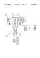
- FIG. 2is a block diagram illustrating one embodiment of a control circuit for a single speed DC fan
- FIG. 3is an electrical schematic illustrating the control circuit of FIG. 2 in greater detail
- FIG. 4is a block diagram illustrating one embodiment of a cooling system for a personal computer that incorporates a control system for controlling a plurality of fans used to cool a computer;
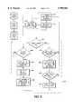
- FIG. 5is a block diagram and flow chart illustrating the operation of the control system for controlling a plurality of fans used to cool a computer.
- FIG. 1illustrates a typical cooling fan assembly 100 used in one embodiment of the invention.
- the cooling fan assembly 100includes a fan 101 that has a fan blade 102 that is mounted about a shaft 104 so as to be positioned within a housing 106.
- the housing 106is attached to a mount 108 that is mounted in the personal computer so that the fan blades 102 can cool an electrical component 110.
- the cooling fan assembly 100is mounted on posts 112 that are attached to a printed circuit board 114 so that the cooling fan blades 102 blow cool air over an integrated circuit 110 that is mounted on the printed circuit board 114. In this manner, the operation of the fan assembly 100 reduces the ambient temperature surrounding the integrated circuit 110 and thereby dissipates the heat that is produced by the integrated circuit 110.
- the fan 101may be mounted in any of a number of well-known manners without departing from the spirit of the invention.
- the fanmay also be mounted in a sidewall of a chassis of the computer so as to allow the fan to draw cool air into the chassis from the outside environment or to expel hot air from the chassis to the cooler outside environment.
- a control circuit 120(FIG. 2) is used to control the operation of the fan assembly 100 in a manner that will be described below.
- the fan assembly 100includes a DC fan 101 such as a Model FBA09Ap12M single speed fan manufactured by Panasonic. It will be appreciated from the following discussion that the control circuit 120 of this embodiment can be used in conjunction with DC fan assemblies such as single speed fans that are mounted in any of a number of well-known manners within the chassis of a personal computer or any other electronic device requiring forced air cooling.
- the control circuit 120is described in greater detail. Specifically, the DC fan 101 is electrically connected between a positive voltage source 122 and a negative voltage source 124. A zener fixed voltage divider 126 is connected in series between the DC fan 100 and the positive voltage source 122. Similarly, an electronic switch 128 is also connected in series between the DC fan 101 and the positive voltage source 122 so that the electronic switch 128 is connected in parallel with the zener fixed voltage divider 126.
- the control circuit 120operates as follows.
- the DC fan 101receives the full differential between the positive voltage source 122 and the negative voltage source 124 when the electronic switch 128 is closed.
- the DC fan 101sees a smaller applied voltage when the electronic switch 128 is opened and the voltage is applied across the zener fixed voltage divider 126.
- a zener fixed voltage divider 126reduces the voltage that is applied across the DC fan by a known amount, V Z .
- V Za known amount
- the voltage drop V Z across the zener fixed voltage divideris generally independent of the current that is being drawn by the fan 101. Specifically, different fans from different manufacturers will draw different amounts of current. If a resistor network were used to produce the voltage drop for low speed operation of the fan, the resistor network would have to be tailored for each manufacturer's fans. Using a zener diode based voltage divider results in substantially the same voltage drop occurring regardless of the current that is being drawn by the fan 101.
- FIG. 3is an electrical schematic which illustrates one embodiment of the fan control circuit 120 in greater detail.
- the electronic switch 128 in this embodimentis comprised of an open collector gate, P-channel MOSFET.
- the MOSFET switch 128receives a speed control signal from a speed control circuit (not shown) through a gate 130.
- the speed control signalcan be a control signal that is provided by a processor of the personal computer.
- the processorwould typically receive a signal from a tachometer associated with the fan and use this signal to adjust the speed of the fan to optimize the fan performance.
- a control systemthat can be used in conjunction with the fan speed control circuit 120 will be described in greater detail in reference to FIGS. 4-6 below. This embodiment of a control system senses the speed of one of a plurality of fans and then induces other fans within the system to operate at higher speeds upon sensing that a fan is no longer operating in a desired manner.
- the speed control signalcan be used to enable or disable the MOSFET switch 128.
- the MOSFET switch 128When the MOSFET switch 128 is enabled, the 12 volts DC power from the power supply is applied across a biasing resistor 134 such as a 1 Kohm resistor that is positioned in parallel with the fan 101.
- the MOSFET switch 128When the MOSFET switch 128 is enabled, the fan 101 effectively sees the entire 12 volts DC from the power supply across its input and output. This results in the fan 101 operating at a higher speed.
- the fan 101provides greater cooling capacity at a cost of increased power consumption by the fan assembly 101, greater wear on the fan 101 and more noise.
- a noise filtering capacitor 136may also be connected in parallel to the biasing resistor 134 and the positive and negative inputs of the fan assembly 100 in a well known manner.
- the speed control signalcan be used to open the MOSFET switch 128 so that the fan assembly 100 only sees 8.7 volts DC which results in the fan 101 operating at a slower speed.
- the zener diodeexperiences zener breakdown which effectively results in the zener diode operating as a low resistance conductor while reducing the voltage that is applied across the fan 101 to 8.7 volts.
- control circuitry 120is capable of operating a single speed DC fan 101 at a low speed by applying only 8.7 volts DC to the fan, thereby causing the fan 101 to spin at a slower speed and thereby prolonging the life of the fan and decreasing the noise produced by the fan.
- control circuit 120can also be configured so as to apply 12 volts DC to thereby operate the fan 101 at a higher speed which will result in more cooling of the computer components.
- the circuit 120 of this embodimentalso includes a biasing resistor 132 such as a 33 Kohm resistor which is selected so that when the speed control input signal is to turn the gate 128 off, the gate is open and the resistor 132 between the gate of the MOSFET 128 and the source of the MOSFET 128 biases the MOSFET in the off condition.
- a biasing resistor 132such as a 33 Kohm resistor which is selected so that when the speed control input signal is to turn the gate 128 off, the gate is open and the resistor 132 between the gate of the MOSFET 128 and the source of the MOSFET 128 biases the MOSFET in the off condition.
- the speed control inputis such as to bias the MOSFET 128 to turn on, the gate pin of the MOSFET 128 is pulled to ground giving the 12 volts across the gate-source junction and thereby turning the MOSFET switch on and shorting across the zener diode 126.
- this embodiment of the control circuitis capable of being used in conjunction with a DC fan so as to operate the DC fan 101 at a variety of speeds.
- the control circuit 120can therefore be used to increase or decrease the speed of the fan 101 as required to achieve the desired cooling effect of the components while reducing the wear and tear on the fans and the noise produced by the fans.
- the use of the zener diodewill allow the circuit 120 to be used with a plurality of different fans from different manufacturers while still providing the same voltage differential between low speed and high speed operation regardless of the current drawn by the fan.
- FIG. 4is a block diagram which illustrates another implementation of a control circuit 220 which is similar to the control circuit 120 described above in reference to FIGS. 2 and 3. Specifically, in FIG. 4, the control circuit 220 is adapted to control the speed of a plurality of DC fans 202 which are substantially similar to the fan 101 described above.
- the control circuit 220includes an electronic switch 228 similar to the electronic switch 128 that is described above.
- the electronic switch 228is connected in series with the fans 202 which are connected in parallel.
- the electronic switch 228is also connected in parallel to a zener fixed voltage divider 226 similar to the voltage divider 126 described above.
- the control circuit 220also includes a microprocessor 230 which receives signals from tachometer outputs 240 that are attached to each of the fans 202.
- the fans 202see a lower DC voltage as a result of the zener voltage divider 226 being in series with the fans 202.
- the microprocessor 230is adapted to send a control signal along the switch control signal line 250 to the electronic switch 228.
- the electronic switch 228then shorts out a zener fixed voltage divider 226. This results in the full voltage differential between a positive voltage source 222 and a negative voltage source 224 being applied across the inputs to the fans 202 in the manner that was described above.
- control system 200is adapted to determine when one of a plurality of fans 202 is no longer operating such that the cooling system 200 is no longer providing adequate cooling to the computer. At which point, the microprocessor 230 provides a signal on the switch control signal line 250 to enable the electronic switch 228. This results in the zener fixed voltage divider 226 being shorted out and a greater voltage being applied to the DC fans 202. This results in the DC fans 202 that are continuing to operate to increase their speed of rotation, thereby increasing their cooling capacity.
- the microprocessor 230continues to monitor the tachometer output 240 of the plurality of fans 202 such that when the fan that is operating incorrectly comes back on line, the microprocessor monitor then sends a signal along the switch control signal line 250 to the electronic switch 228 which opens the electronic switch 228.
- the voltage that is applied to the DC fan 202is lowered as a result of these zener fixed voltage divider 226 being positioned in series with the fans. This will result in the fans 202 operating at a slower speed, thereby decreasing the wear and tear on the fans and the noise produced by the fans.
- the control system 200is capable of monitoring the speed of rotation of a number of fans when the fans were operating at a first speed.
- the microprocessor 230determines that one of the fans is no longer operating, the microprocessor can then increase the voltage to the remaining operating fans to thereby increase the speed of operation of the remaining fans 202 and to thereby increase the cooling capacity provided by these fans. Consequently, the control system 200 is capable of correcting a situation where the failure of one or more of the fans would result in too little cooling capacity being provided by the remaining fans.
- FIG. 5is a block diagram which illustrates the operation and configuration of the control system 200 in greater detail.
- the tachometer outputs of each of the fans 202are provided to a multiplexer 260.
- the fans 202include intrinsic tachometers.
- an external sensoris used with a simpler fan, in the manner described below in reference to FIG. 6, to provide a tachometer output to the multiplexer 260.
- the multiplexer 260is under the control of the microprocessor 230 in the sense that the microprocessor 230 can, in a state 272, induce the multiplexer 260 to sample each of the tachometer outputs 240 from the fans 202.
- the tachometer outputis provided to the microprocessor 230 such that the microprocessor 230, in a state 274, can sense the speed of the fan 202.
- the speed of the fan 202is directly proportional to the cooling capacity that is provided by the fan 202.
- the microprocessor 230can then determine, in decision state 276, whether the speed of the fan 202 is above the desired limit.
- the microprocessor 230can then determine, in state 280, whether the fan speed is equal to zero based upon the fan speed that was detected in state 274. In this embodiment, if the fan speed detected by the microprocessor 230 in state 274 is equal to zero, this means that the fan is being replaced. As will be described in greater detail below, once the fan is replaced, the voltage applied to the plurality of fans can be lowered to the lower voltage value.
- the microprocessor 230sets, in state 282, a bit entitled hot -- swap -- fan register equal to one. This indicates this fan is being replaced. Subsequently, the microprocessor 230 then sets a bit in the fan -- fault register, in state 284, corresponding to the fan 202 to one. Setting the bit in the fan -- fault register to one results in a high output being provided, in state 286, along the switch control signal line 250 (FIG. 4), thereby closing the switch 228 and shorting out the fixed zener voltage divider 226 causing the remaining fans 202 to operate at the higher speed.
- the microprocessor 230also sends a signal, in state 286, to a non-volatile RAM (not shown) recording that the fan 202 is no longer operating correctly. This allows a maintenance person to identify which fans are not operating correctly for subsequent replacement and/or repair of the incorrectly operating fans 202.
- the microprocessor 230is capable of evaluating the speed of a particular fan 202 and determining whether it is underspeed. The microprocessor 230 also determines whether the speed is equal to zero or is simply less than the desired speed. The microprocessor 230 also induces a high output to be provided on the switch control signal line 250 to the electronic switch 228 upon sensing that any of the fans 202 is operating at a speed that is less than the desired limit. This results in a greater voltage being applied to the remaining fans 202 thereby increasing the speed of operation of these fans to offset the loss of cooling capacity due to the incorrectly operating fan.
- the processor 230determines, in decision state 276, that the speed of the fan 202 is above the minimum limit, the processor 230 then determines, in decision state 290, whether the hot -- swap -- fan register bit has been set for this particular fan 202. If the hot -- swap -- fan bit has been set, that means that the fan was previously stopped and is now operating correctly which indicates the bad fan 202 has been replaced.
- the processor 230clearing, in state 292, the bits and fan -- fault and hot -- swap -- fan registers corresponding to this particular fan 202.
- the processor 230determines, in decision state 294, whether the fan -- fault register is all clear and, if so, the processor 230 then sends a low signal on the switch control signal line 250 to the electronic switch 228 (FIG. 4) to open the electronic switch 228.
- the processor 230sequentially evaluates the tachometer output lines of each of the fans 202 to determine the speed of the fan 202. If any one of the fans is not operating at the correct speed, the processor 230 then sends a signal to the switch thereby disabling the zener voltage divider 226 and increasing the voltage to the remaining fans 202 to cause these fans 202 to speed up. The processor 230 continues to monitor the speed of operation of each of the fans 202, including any fan that was previously sensed as not operating correctly. If the fans are operating correctly, then the processor 230 opens the switch 228 and positions the voltage divider 226 in series with the DC fans 202 to thereby reduce the voltage that is being applied to the DC fans.
- a circuit for controlling the operation of fanwhich incorporates a zener diode divider that can be selectively switched into series with the power input of a fan to decrease the voltage that is provided to the fan. This allows the fan to operate at a lower speed thereby prolonging the longevity of the fan and also decreasing the noise produced by the fan.
- a cooling systemis provided which incorporates the zener diode control circuit and a plurality of fans.
- the cooling systemmay also include a microprocessor that senses the speed of operation of the plurality of fans and, upon sensing that one or more fans are no longer operating at a desired speed, the microprocessor closes a switch to short out the zener bridge divider so that the remaining fans receive a higher voltage to offset the loss of cooling capacity resulting from the loss of the fan.
- a microprocessorthat senses the speed of operation of the plurality of fans and, upon sensing that one or more fans are no longer operating at a desired speed, the microprocessor closes a switch to short out the zener bridge divider so that the remaining fans receive a higher voltage to offset the loss of cooling capacity resulting from the loss of the fan.
Landscapes
- Engineering & Computer Science (AREA)
- Theoretical Computer Science (AREA)
- General Engineering & Computer Science (AREA)
- General Physics & Mathematics (AREA)
- Physics & Mathematics (AREA)
- Computer Hardware Design (AREA)
- Quality & Reliability (AREA)
- Computer Security & Cryptography (AREA)
- Software Systems (AREA)
- Signal Processing (AREA)
- Computer Networks & Wireless Communication (AREA)
- Computing Systems (AREA)
- Mechanical Engineering (AREA)
- Human Computer Interaction (AREA)
- Cooling Or The Like Of Electrical Apparatus (AREA)
Abstract
Description
______________________________________ Application Filing Title No. Date ______________________________________ "Hardware and Software Architecture for 60/047,016 May 13, 1997 Inter-Connecting an Environmental Management System with a Remote Interface" "Self Management Protocol for a 60/046,416 May 13, 1997 Fly-By-Wire Service Processor" "Isolated Interrupt Structure for 60/047,003 May 13, 1997 Input/Output Architecture" "Three Bus Server Architecture with a 60/046,490 May 13, 1997 Legacy PCI Bus and Mirrored I/O PCI Buses" "Computer System Hardware Infra- 60/046,398 May 13, 1997 structure for Hot Plugging Single and Multi-Function PC Cards Without Embedded Bridges" "Computer System Hardware Infra- 60/046,312 May 13, 1997 structure for Hot Plugging Multi-Function PCI Cards With Embedded Bridges" ______________________________________
______________________________________ Appendix A Incorporation by Reference of Commonly Owned Applications The following patent applications, commonly owned and filed October 1, 1997, are hereby incorporated herein in their entirety by reference thereto: Application Attorney Title No. Docket No. ______________________________________ "System Architecture for Remote 08/942,160 MNFRAME.002A1 Access and Control of Environ- mental Management" "Method of Remote Access and 08/942,215 MNFRAME.002A2 Control of Environmental Management" "System for Independent 08/942,410 MNFRAME.002A3 Powering of Diagnostic Processes on a Computer System" "Method of Independent Powering 08/942,320 MNFRAME.002A4 of Diagnostic Processes on a Computer System" "Diagnostic and Managing 08/942,402 MNFRAME.005A1 Distributed Processor System" "Method for Managing a Distri- 08/942,448 MNFRAME.005A2 buted Processor System" "System for Mapping Environ- 08/942,222 MNFRAME.005A3 mental Resources to Memory for Program Access" "Method for Mapping Environ- 08/942,214 MNFRAME.005A4 mental Resources to Memory for Program Access" "Hot Add of Devices Software 08/942,309 MNFRAME.006A1 Architecture" "Method for The Hot Add of 08/942,306 MNFRAME.006A2 Devices" "Hot Swap of Devices Software 08/942,311 MNFRAME.006A3 Architecture" "Method for The Hot Swap of 08/942,457 MNFRAME.006A4 Devices" "Method for the Hot Add of a 08/943,072 MNFRAME.006A5 Network Adapter on a System Including a Dynamically Loaded Adapter Driver" "Method for the Hot Add of a 08/942,069 MNFRAME.006A6 Mass Storage Adapter on a System Including a Statically Loaded Adapter Driver" "Method for the Hot Add of a 08/942,465 MNFRAME.006A7 Network Adapter on a System Including a Statically Loaded Adapter Driver" "Method for the Hot Add of a 08/962,963 MNFRAME.006A8 Mass Storage Adapter on a System Including a Dynamically Loaded Adapter Driver" "Method for the Hot Swap of a 08/943,078 MNFRAME.006A9 Network Adapter on a System Including a Dynamically Loaded Adapter Driver" "Method for the Hot Swap of a 08/942,336 MNFRAME.006A10 Mass Storage Adapter on a System Including a Statically Loaded Adapter Driver" "Method for the Hot Swap of a 08/942,459 MNFRAME.006A11 Network Adapter on a System Including a Statically Loaded Adapter Driver" "Method for the Hot Swap of a 08/942,458 MNFRAME.006A12 Mass Storage Adapter on a System Including a Dynamically Loaded Adapter Driver" "Method of Performing an 08/942,463 MNFRAME.008A Extensive Diagnostic Test in Conjunction with a BIOS Test Routine" "Apparatus for Performing an 08/942,163 MNFRAME.009A Extensive Diagnostic Test in Conjunction with a BIOS Test Routine" "Configuration Management 08/941,268 MNFRAME.010A Method for Hot Adding and Hot Replacing Devices" "Configuration Management 08/942,408 MNFRAME.011A System for Hot Adding and Hot Replacing Devices" "Apparatus for Interfacing Buses" 08/942,382 MNFRAME.012A "Method for Interfacing Buses" 08/942,413 MNFRAME.013A "Computer Fan Speed Control 08/942,216 MNFRAME.017A Method" "System for Powering Up and 08/943,076 MNFRAME.018A Powering Down a Server" "Method of Powering Up and 08/943,077 MNFRAME.019A Powering Down a Server" "System for Resetting a Server" 08/942,333 MNFRAME.020A "Method of Resetting a Server" 08/942,405 MNFRAME.021A "System for Displaying Flight 08/942,070 MNFRAME.022A Recorder" "Method of Displaying Flight 08/942,068 MNFRAME.023A Recorder" "Synchronous Communication 08/943,355 MNFRAME.024A Interface" "Synchronous Communication 08/942,004 MNFRAME.025A Emulation" "Software System Facilitating the 08/942,317 MNFRAME.026A Replacement or Insertion of Devices in a Computer System" "Method for Facilitating the 08/942,316 MNFRAME.027A Replacement or Insertion of Devices in a Computer System" "System Management Graphical 08/943,357 MNFRAME.028A User Interface" "Display of System Information" 08/942,195 MNFRAME.029A "Data Management System 08/942,129 MNFRAME.030A Supporting Hot Plug Operations on a Computer" "Data Management Method 08/942,124 MNFRAME.031A Supporting Hot Plug Operations on a Computer" "Alert Configurator and Manager" 08/942,005 MNFRAME.032A "Managing Computer System 08/943,356 MNFRAME.033A Alerts" "Computer Fan Speed Control 08/940,301 MNFRAME.034A System" "Computer Fan Speed Control 08/941,267 MNFRAME.035A System Method" "Black Box Recorder for 08/942,381 MNFRAME.036A Information System Events" "Method of Recording 08/942,164 MNFRAME.037A Information System Events" "Method for Automatically 08/942,168 MNFRAME.040A Reporting a System Failure in a Server" "System for Automatically 08/942,384 MNFRAME.041A Reporting a System Failure in a Server" "Expansion of PCI Bus Loading 08/942,404 MNFRAME.042A Capacity" "Method for Expanding PCI Bus 08/942,223 MNFRAME.043A Loading Capacity" "System for Displaying System 08/942,347 MNFRAME.044A Status" "Method of Displaying System 08/942,071 MNFRAME.045A Status" "Fault Tolerant Computer System" 08/942,194 MNFRAME.046A "Method for Hot Swapping of 08/943,044 MNFRAME.047A Network Components" "A Method for Communicating a 08/942,221 MNFRAME.048A Software Generated Pulse Waveform Between Two Servers in a Network" "A System for Communicating a 08/942,409 MNFRAME.049A Software Generated Pulse Waveform Between Two Servers in a Network" "Method for Clustering Software 08/942,318 MNFRAME.050A Applications" "System for Clustering Software 08/942,411 MNFRAME.051A Applications" "Method for Automatically 08/942,319 MNFRAME.052A Configuring a Server after Hot Add of a Device" "System for Automatically 08/942,331 MNFRAME.053A Configuring a Server after Hot Add of a Device" "Method of Automatically 08/942,412 MNFRAME.054A Configuring and Formatting a Computer System and Installing Software" "System for Automatically 08/941,955 MNFRAME.055A Configuring and Formatting a Computer System and Installing Software" "Determining Slot Numbers in a 08/942,462 MNFRAME.056A Computer" "System for Detecting Errors 08/942,169 MNFRAME.058A in a Network" "Method of Detecting Errors 08/940,302 MNFRAME.059A in a Network" "System for Detecting Network 08/942,407 MNFRAME.060A Errors" "Method of Detecting Network 08/942,573 MNFRAME.061A Errors" ______________________________________
Claims (19)
Priority Applications (1)
| Application Number | Priority Date | Filing Date | Title |
|---|---|---|---|
| US08/942,447US5990582A (en) | 1997-05-13 | 1997-10-01 | Computer fan speed control device |
Applications Claiming Priority (7)
| Application Number | Priority Date | Filing Date | Title |
|---|---|---|---|
| US4649097P | 1997-05-13 | 1997-05-13 | |
| US4641697P | 1997-05-13 | 1997-05-13 | |
| US4701697P | 1997-05-13 | 1997-05-13 | |
| US4639897P | 1997-05-13 | 1997-05-13 | |
| US4631297P | 1997-05-13 | 1997-05-13 | |
| US4700397P | 1997-05-13 | 1997-05-13 | |
| US08/942,447US5990582A (en) | 1997-05-13 | 1997-10-01 | Computer fan speed control device |
Publications (1)
| Publication Number | Publication Date |
|---|---|
| US5990582Atrue US5990582A (en) | 1999-11-23 |
Family
ID=27567995
Family Applications (1)
| Application Number | Title | Priority Date | Filing Date |
|---|---|---|---|
| US08/942,447Expired - LifetimeUS5990582A (en) | 1997-05-13 | 1997-10-01 | Computer fan speed control device |
Country Status (1)
| Country | Link |
|---|---|
| US (1) | US5990582A (en) |
Cited By (35)
| Publication number | Priority date | Publication date | Assignee | Title |
|---|---|---|---|---|
| US6186889B1 (en)* | 1999-01-08 | 2001-02-13 | Lucent Technologies Inc. | Fan assembly module |
| WO2001049093A1 (en)* | 1999-12-23 | 2001-07-05 | Analog Devices, Inc. | Fan speed control system |
| US6259172B1 (en)* | 1998-07-15 | 2001-07-10 | Samsung Electronics Co., Ltd. | Cooling fan controlling apparatus for computer |
| US6265790B1 (en)* | 1998-10-07 | 2001-07-24 | Intel Corporation | Computer system fan circuit |
| US6400113B1 (en) | 2000-07-19 | 2002-06-04 | International Business Machines Corporation | Apparatus and method for monitoring fan speeds within a computing system |
| US6428282B1 (en)* | 1999-06-14 | 2002-08-06 | Hewlett-Packard Company | System with fan speed synchronization control |
| US6617709B2 (en)* | 2000-11-10 | 2003-09-09 | Delta Electronics, Inc. | Controlling device for a heat-dissipating system |
| US20030193307A1 (en)* | 2002-04-10 | 2003-10-16 | Steven Burstein | Method and apparatus for controlling a fan |
| US6657325B2 (en)* | 2001-01-11 | 2003-12-02 | International Business Machines Corporation | Multiple fan sensing circuit and method for monitoring multiple cooling fans utilizing a single fan sense input |
| US20040001542A1 (en)* | 2002-07-01 | 2004-01-01 | Miller Wayne A. | Method and apparatus for measuring the rotational speed of a fan |
| US20040027763A1 (en)* | 2002-08-06 | 2004-02-12 | Dhuey Michael J. | Quiet fan speed control |
| US6747424B1 (en) | 2000-10-02 | 2004-06-08 | International Business Machines Corporation | Integrated fan speed control and fault detection circuitry |
| GB2396258A (en)* | 2002-12-11 | 2004-06-16 | Eric Tsai | Control device for fans in a computer power supply |
| US20040228091A1 (en)* | 2003-03-31 | 2004-11-18 | Tatsuya Miyairi | Information processing apparatus and fan control method |
| US20040257024A1 (en)* | 2003-06-11 | 2004-12-23 | Marando Eileen M. | Programmable PWM stretching for tachometer measurement |
| US20050040777A1 (en)* | 2003-08-08 | 2005-02-24 | Len Bekker | Method and apparatus for generating accurate fan tachometer readings |
| US6874327B1 (en) | 2003-12-01 | 2005-04-05 | Standard Microsystems Corporation | Fan control system with improved temperature resolution |
| US20050156544A1 (en)* | 2004-01-16 | 2005-07-21 | Marando Eileen M. | Autofan combination of zones |
| US20050186083A1 (en)* | 2004-02-23 | 2005-08-25 | Standard Microsystems Corporation | Mapping a plurality of sensors to respective zones in a fan control system |
| US20050217293A1 (en)* | 2004-03-31 | 2005-10-06 | Thomson Licensing S.A. | Circuit for controlling a cooling device |
| US20050238336A1 (en)* | 2003-09-22 | 2005-10-27 | Bekker Leonid A | Method and apparatus to achieve accurate fan tachometer with programmable look-up table |
| US20050256670A1 (en)* | 2004-05-11 | 2005-11-17 | Standard Microsystems Corporation | Method and apparatus to achieve accurate fan tachometer readings for fans with different speeds |
| US20060108962A1 (en)* | 2004-11-24 | 2006-05-25 | Standard Microsystems Corporation | Adaptive controller for PC cooling fans |
| US20060228237A1 (en)* | 2004-10-19 | 2006-10-12 | Winkler Wolfgang A | Assembly used for cooling a circuit board or similar |
| US20060232931A1 (en)* | 2005-04-07 | 2006-10-19 | Harman Becker Automotive Systems Gmbh | Fan for ventilating electrical and electronic equipment |
| US20060232231A1 (en)* | 2005-04-18 | 2006-10-19 | Delta Electronics, Inc. | Fan module and control device thereof |
| US7151349B1 (en) | 2004-04-08 | 2006-12-19 | Analog Devices, Inc. | Fan speed control |
| US20070113107A1 (en)* | 2005-11-16 | 2007-05-17 | Fujitsu Limited | Control device |
| US20070145934A1 (en)* | 2005-12-27 | 2007-06-28 | Standard Microsystems Corporation | Dynamic hysteresis for autofan control |
| US20080042603A1 (en)* | 2006-08-17 | 2008-02-21 | Zippy Technology Corp. | Cooling-fan rotation-speed control circuit |
| CN100400890C (en)* | 2005-04-26 | 2008-07-09 | 台达电子工业股份有限公司 | Fan module and control device thereof |
| US20090220219A1 (en)* | 2008-02-29 | 2009-09-03 | Mcleod Scott C | Delta-Sigma Modulator for a Fan Driver |
| US7667733B1 (en) | 2003-07-18 | 2010-02-23 | Oswald David L | Computer monitor receiver |
| US20100215510A1 (en)* | 2009-02-26 | 2010-08-26 | Chao-Ming Tsai | RPM Controller Using Drive Profiles |
| US20100244759A1 (en)* | 2009-03-31 | 2010-09-30 | Lenovo(Singapore) Pte. Ltd. | Safety features for moving components of electronic devices |
Citations (70)
| Publication number | Priority date | Publication date | Assignee | Title |
|---|---|---|---|---|
| US3345551A (en)* | 1966-05-10 | 1967-10-03 | Bendix Corp | Variable speed control for a dc motor |
| US3940671A (en)* | 1974-08-12 | 1976-02-24 | Chicago Dynamic Industries, Inc. | Control circuit for amusement device |
| US4296363A (en)* | 1974-09-09 | 1981-10-20 | Outboard Marine Corporation | Speed selection for a direct current permanent magnet motor |
| US4449182A (en)* | 1981-10-05 | 1984-05-15 | Digital Equipment Corporation | Interface between a pair of processors, such as host and peripheral-controlling processors in data processing systems |
| US4465958A (en)* | 1982-04-26 | 1984-08-14 | Allied Corporation | Motor speed control circuit |
| US4751440A (en)* | 1987-11-16 | 1988-06-14 | Dang Chi H | Electrical control circuit for isokinetic exercise equipment |
| US4835737A (en)* | 1986-07-21 | 1989-05-30 | American Telephone And Telegraph Company, At&T Bell Laboratories | Method and apparatus for controlled removal and insertion of circuit modules |
| US4949245A (en)* | 1988-10-21 | 1990-08-14 | Modular Computer Systems, Inc. | Intermediate memory system for connecting microcomputers to a rotating disk memory |
| US4992709A (en)* | 1989-06-20 | 1991-02-12 | Lightolier, Inc. | Switching circuit providing adjustable capacitive series voltage dropping circuit with a fractional horsepower motor |
| US4999787A (en)* | 1988-07-15 | 1991-03-12 | Bull Hn Information Systems Inc. | Hot extraction and insertion of logic boards in an on-line communication system |
| US5210855A (en)* | 1989-06-09 | 1993-05-11 | International Business Machines Corporation | System for computer peripheral bus for allowing hot extraction on insertion without disrupting adjacent devices |
| US5269011A (en)* | 1990-09-24 | 1993-12-07 | Emc Corporation | Dynamically reconfigurable data storage system with storage system controllers selectively operable as channel adapters on storage device adapters |
| US5272584A (en)* | 1990-12-07 | 1993-12-21 | International Business Machines Corporation | Hot-plugging circuit for the interconnection of cards to boards |
| US5317693A (en)* | 1991-04-04 | 1994-05-31 | Digital Equipment Corporation | Computer peripheral device network with peripheral address resetting capabilities |
| US5329625A (en)* | 1992-04-15 | 1994-07-12 | International Business Machines Corp. | System to service processor interface for a tablet computer |
| US5337413A (en)* | 1992-02-06 | 1994-08-09 | Tandem Computers Incorporated | Environment monitoring system for standard interface bus computer systems |
| US5386567A (en)* | 1992-01-20 | 1995-01-31 | International Business Machines Corp. | Hot removable and insertion of attachments on fully initialized computer systems |
| US5483419A (en)* | 1991-09-24 | 1996-01-09 | Teac Corporation | Hot-swappable multi-cartridge docking module |
| US5493574A (en)* | 1992-09-24 | 1996-02-20 | Zilog, Inc. | Power efficient RAM disk and a method of emulating a rotating memory disk |
| US5493666A (en)* | 1990-03-19 | 1996-02-20 | Apple Computer, Inc. | Memory architecture using page mode writes and single level write buffering |
| US5517646A (en)* | 1994-04-25 | 1996-05-14 | Compaq Computer Corp. | Expansion device configuration system having two configuration modes which uses automatic expansion configuration sequence during first mode and configures the device individually during second mode |
| US5528721A (en)* | 1992-05-04 | 1996-06-18 | John Svoboda | Direct current motor speed control apparatus |
| US5555510A (en)* | 1994-08-02 | 1996-09-10 | Intel Corporation | Automatic computer card insertion and removal algorithm |
| US5564024A (en)* | 1994-08-02 | 1996-10-08 | Pemberton; Adam C. | Apparatus for connecting and disconnecting peripheral devices to a powered bus |
| US5568610A (en)* | 1995-05-15 | 1996-10-22 | Dell Usa, L.P. | Method and apparatus for detecting the insertion or removal of expansion cards using capacitive sensing |
| US5577155A (en)* | 1993-12-03 | 1996-11-19 | Buchbinder; Carl | Rectifier based motor speed/brake control |
| US5579491A (en)* | 1994-07-07 | 1996-11-26 | Dell U.S.A., L.P. | Local proactive hot swap request/acknowledge system |
| US5581712A (en)* | 1994-11-17 | 1996-12-03 | Intel Corporation | Method and apparatus for managing live insertion of CPU and I/O boards into a computer system |
| US5588144A (en)* | 1993-12-03 | 1996-12-24 | Hitachi, Ltd. | Storage system having a bus common to a plurality of kinds of groups of packages |
| US5606672A (en)* | 1995-01-27 | 1997-02-25 | Intel Corporation | Method and apparatus for multiplexing signals from a bus bridge to an ISA bus interface and an ATA bus interface |
| US5608876A (en)* | 1995-05-22 | 1997-03-04 | International Business Machines Corporation | Add-in board with enable-disable expansion ROM for PCI bus computers |
| US5615207A (en)* | 1995-06-07 | 1997-03-25 | Advanced Micro Devices, Inc. | Side bus to dynamically off load main bus |
| US5632021A (en)* | 1995-10-25 | 1997-05-20 | Cisco Systems Inc. | Computer system with cascaded peripheral component interconnect (PCI) buses |
| US5638289A (en)* | 1994-03-18 | 1997-06-10 | Fujitsu Limited | Method and apparatus allowing hot replacement of circuit boards |
| US5644470A (en)* | 1995-11-02 | 1997-07-01 | International Business Machines Corporation | Autodocking hardware for installing and/or removing adapter cards without opening the computer system cover |
| US5644731A (en)* | 1995-07-07 | 1997-07-01 | Sun Microsystems, Inc. | Method and apparatus for hot plugging/unplugging a sub-system to an electrically powered system |
| US5651006A (en)* | 1994-06-14 | 1997-07-22 | Hitachi, Ltd. | Hierarchical network management system |
| US5652832A (en)* | 1995-11-13 | 1997-07-29 | Systemsoft Corporation | Method and apparatus for diagnosis and correction of peripheral device allocation faults |
| US5680288A (en)* | 1995-06-07 | 1997-10-21 | International Business Machines Corporation | Hot plugging of an adapter card |
| US5687079A (en)* | 1994-04-08 | 1997-11-11 | Sun Microsystems, Inc. | Method and apparatus for improved control of computer cooling fan speed |
| US5696970A (en)* | 1993-04-01 | 1997-12-09 | Intel Corporation | Architecture for implementing PCMCIA card services under the windows operating system in enhanced mode |
| US5726506A (en)* | 1995-06-05 | 1998-03-10 | Alantec Corporation | Hot insertion power arrangement |
| US5740378A (en)* | 1995-08-17 | 1998-04-14 | Videoserver, Inc. | Hot swap bus architecture |
| US5748426A (en)* | 1996-04-29 | 1998-05-05 | Paradyne Corporation | Method for interfacing to a powered bus |
| US5747889A (en)* | 1996-07-31 | 1998-05-05 | Hewlett-Packard Company | Redundant power supply and storage system |
| US5754797A (en)* | 1995-02-13 | 1998-05-19 | Mitsubishi Denki Kabushiki Kaisha | Apparatus for allowing smooth hot insertion and removal of a peripheral by gradually applying and removing power to the peripheral |
| US5761045A (en)* | 1995-12-22 | 1998-06-02 | Apple Computer, Inc. | Modular, redundant, hot swappable, blind mate power supply system |
| US5761033A (en)* | 1993-02-19 | 1998-06-02 | Sejus Corporation | Open computer system with externally interconnected peripheral modules |
| US5764968A (en)* | 1995-08-21 | 1998-06-09 | Kabushiki Kaisha Toshiba | Clock supply permission/inhibition control system |
| US5765198A (en)* | 1996-02-01 | 1998-06-09 | Cray Research, Inc. | Transparent relocation of real memory addresses in the main memory of a data processor |
| US5768541A (en)* | 1995-06-15 | 1998-06-16 | Dell U.S.A., L.P. | System for hot-plugging peripheral device to computer bus and disconnecting peripheral device upon detecting predetermined sequence of keystrokes inputted by user through keyboard |
| US5768542A (en)* | 1994-06-08 | 1998-06-16 | Intel Corporation | Method and apparatus for automatically configuring circuit cards in a computer system |
| US5781798A (en)* | 1993-12-30 | 1998-07-14 | International Business Machines Corporation | Method and apparatus for providing hot swapping capability in a computer system with static peripheral driver software |
| US5784576A (en)* | 1996-10-31 | 1998-07-21 | International Business Machines Corp. | Method and apparatus for adding and removing components of a data processing system without powering down |
| US5790831A (en)* | 1994-11-01 | 1998-08-04 | Opti Inc. | VL-bus/PCI-bus bridge |
| US5793987A (en)* | 1996-04-18 | 1998-08-11 | Cisco Systems, Inc. | Hot plug port adapter with separate PCI local bus and auxiliary bus |
| US5794035A (en)* | 1993-12-13 | 1998-08-11 | International Business Machines Corporation | Device driver and input/output hardware research manager |
| US5796185A (en)* | 1996-10-15 | 1998-08-18 | Sony Corporation | Circuit card present sense and protective power supply inhibit for airborne application of ATM switch unit |
| US5796981A (en)* | 1994-09-16 | 1998-08-18 | Cirrus Logic, Inc. | Method and apparatus for providing register compatibility between non-identical integrated circuits |
| US5799036A (en)* | 1995-06-29 | 1998-08-25 | Staples; Leven E. | Computer system which provides analog audio communication between a PC card and the computer's sound system |
| US5798828A (en)* | 1996-03-13 | 1998-08-25 | American Research Corporation Of Virginbia | Laser aligned five-axis position measurement device |
| US5802552A (en)* | 1993-06-30 | 1998-09-01 | Intel Corporation | System and method for allocating and sharingpage buffers for a flash memory device |
| US5802393A (en)* | 1993-11-12 | 1998-09-01 | International Business Machines Corporation | Computer system for detecting and accessing BIOS ROM on local bus peripheral bus or expansion bus |
| US5802269A (en)* | 1996-06-28 | 1998-09-01 | Intel Corporation | Method and apparatus for power management of distributed direct memory access (DDMA) devices |
| US5805834A (en)* | 1994-03-30 | 1998-09-08 | Zilog, Inc. | Hot reconfigurable parallel bus bridging circuit |
| US5809224A (en)* | 1995-10-13 | 1998-09-15 | Compaq Computer Corporation | On-line disk array reconfiguration |
| US5812858A (en)* | 1994-09-16 | 1998-09-22 | Cirrus Logic, Inc. | Method and apparatus for providing register and interrupt compatibility between non-identical integrated circuits |
| US5812757A (en)* | 1993-10-08 | 1998-09-22 | Mitsubishi Denki Kabushiki Kaisha | Processing board, a computer, and a fault recovery method for the computer |
| US5815117A (en)* | 1997-01-02 | 1998-09-29 | Raytheon Company | Digital direction finding receiver |
| US5822547A (en)* | 1996-05-31 | 1998-10-13 | Texas Instruments Incorporated | Method and apparatus for providing a portable computer with hot pluggable modular bays |
- 1997
- 1997-10-01USUS08/942,447patent/US5990582A/ennot_activeExpired - Lifetime
Patent Citations (73)
| Publication number | Priority date | Publication date | Assignee | Title |
|---|---|---|---|---|
| US3345551A (en)* | 1966-05-10 | 1967-10-03 | Bendix Corp | Variable speed control for a dc motor |
| US3940671A (en)* | 1974-08-12 | 1976-02-24 | Chicago Dynamic Industries, Inc. | Control circuit for amusement device |
| US4296363A (en)* | 1974-09-09 | 1981-10-20 | Outboard Marine Corporation | Speed selection for a direct current permanent magnet motor |
| US4449182B1 (en)* | 1981-10-05 | 1989-12-12 | ||
| US4449182A (en)* | 1981-10-05 | 1984-05-15 | Digital Equipment Corporation | Interface between a pair of processors, such as host and peripheral-controlling processors in data processing systems |
| US4465958A (en)* | 1982-04-26 | 1984-08-14 | Allied Corporation | Motor speed control circuit |
| US4835737A (en)* | 1986-07-21 | 1989-05-30 | American Telephone And Telegraph Company, At&T Bell Laboratories | Method and apparatus for controlled removal and insertion of circuit modules |
| US4751440A (en)* | 1987-11-16 | 1988-06-14 | Dang Chi H | Electrical control circuit for isokinetic exercise equipment |
| US4999787A (en)* | 1988-07-15 | 1991-03-12 | Bull Hn Information Systems Inc. | Hot extraction and insertion of logic boards in an on-line communication system |
| US4949245A (en)* | 1988-10-21 | 1990-08-14 | Modular Computer Systems, Inc. | Intermediate memory system for connecting microcomputers to a rotating disk memory |
| US5210855A (en)* | 1989-06-09 | 1993-05-11 | International Business Machines Corporation | System for computer peripheral bus for allowing hot extraction on insertion without disrupting adjacent devices |
| US4992709A (en)* | 1989-06-20 | 1991-02-12 | Lightolier, Inc. | Switching circuit providing adjustable capacitive series voltage dropping circuit with a fractional horsepower motor |
| US5493666A (en)* | 1990-03-19 | 1996-02-20 | Apple Computer, Inc. | Memory architecture using page mode writes and single level write buffering |
| US5269011A (en)* | 1990-09-24 | 1993-12-07 | Emc Corporation | Dynamically reconfigurable data storage system with storage system controllers selectively operable as channel adapters on storage device adapters |
| US5272584A (en)* | 1990-12-07 | 1993-12-21 | International Business Machines Corporation | Hot-plugging circuit for the interconnection of cards to boards |
| US5317693A (en)* | 1991-04-04 | 1994-05-31 | Digital Equipment Corporation | Computer peripheral device network with peripheral address resetting capabilities |
| US5483419A (en)* | 1991-09-24 | 1996-01-09 | Teac Corporation | Hot-swappable multi-cartridge docking module |
| US5386567A (en)* | 1992-01-20 | 1995-01-31 | International Business Machines Corp. | Hot removable and insertion of attachments on fully initialized computer systems |
| US5337413A (en)* | 1992-02-06 | 1994-08-09 | Tandem Computers Incorporated | Environment monitoring system for standard interface bus computer systems |
| US5329625A (en)* | 1992-04-15 | 1994-07-12 | International Business Machines Corp. | System to service processor interface for a tablet computer |
| US5528721A (en)* | 1992-05-04 | 1996-06-18 | John Svoboda | Direct current motor speed control apparatus |
| US5493574A (en)* | 1992-09-24 | 1996-02-20 | Zilog, Inc. | Power efficient RAM disk and a method of emulating a rotating memory disk |
| US5761033A (en)* | 1993-02-19 | 1998-06-02 | Sejus Corporation | Open computer system with externally interconnected peripheral modules |
| US5696970A (en)* | 1993-04-01 | 1997-12-09 | Intel Corporation | Architecture for implementing PCMCIA card services under the windows operating system in enhanced mode |
| US5802552A (en)* | 1993-06-30 | 1998-09-01 | Intel Corporation | System and method for allocating and sharingpage buffers for a flash memory device |
| US5812757A (en)* | 1993-10-08 | 1998-09-22 | Mitsubishi Denki Kabushiki Kaisha | Processing board, a computer, and a fault recovery method for the computer |
| US5802393A (en)* | 1993-11-12 | 1998-09-01 | International Business Machines Corporation | Computer system for detecting and accessing BIOS ROM on local bus peripheral bus or expansion bus |
| US5577155A (en)* | 1993-12-03 | 1996-11-19 | Buchbinder; Carl | Rectifier based motor speed/brake control |
| US5781767A (en)* | 1993-12-03 | 1998-07-14 | Hitachi, Ltd. | Package blocking method for a storage system having a bus common to a plurality of kinds of groups of packages |
| US5588144A (en)* | 1993-12-03 | 1996-12-24 | Hitachi, Ltd. | Storage system having a bus common to a plurality of kinds of groups of packages |
| US5794035A (en)* | 1993-12-13 | 1998-08-11 | International Business Machines Corporation | Device driver and input/output hardware research manager |
| US5781798A (en)* | 1993-12-30 | 1998-07-14 | International Business Machines Corporation | Method and apparatus for providing hot swapping capability in a computer system with static peripheral driver software |
| US5638289A (en)* | 1994-03-18 | 1997-06-10 | Fujitsu Limited | Method and apparatus allowing hot replacement of circuit boards |
| US5805834A (en)* | 1994-03-30 | 1998-09-08 | Zilog, Inc. | Hot reconfigurable parallel bus bridging circuit |
| US5687079A (en)* | 1994-04-08 | 1997-11-11 | Sun Microsystems, Inc. | Method and apparatus for improved control of computer cooling fan speed |
| US5517646A (en)* | 1994-04-25 | 1996-05-14 | Compaq Computer Corp. | Expansion device configuration system having two configuration modes which uses automatic expansion configuration sequence during first mode and configures the device individually during second mode |
| US5768542A (en)* | 1994-06-08 | 1998-06-16 | Intel Corporation | Method and apparatus for automatically configuring circuit cards in a computer system |
| US5651006A (en)* | 1994-06-14 | 1997-07-22 | Hitachi, Ltd. | Hierarchical network management system |
| US5579491A (en)* | 1994-07-07 | 1996-11-26 | Dell U.S.A., L.P. | Local proactive hot swap request/acknowledge system |
| US5664119A (en)* | 1994-07-07 | 1997-09-02 | Dell Usa, L.P. | Local proactive hot swap request/acknowledge system |
| US5555510A (en)* | 1994-08-02 | 1996-09-10 | Intel Corporation | Automatic computer card insertion and removal algorithm |
| US5564024A (en)* | 1994-08-02 | 1996-10-08 | Pemberton; Adam C. | Apparatus for connecting and disconnecting peripheral devices to a powered bus |
| US5812858A (en)* | 1994-09-16 | 1998-09-22 | Cirrus Logic, Inc. | Method and apparatus for providing register and interrupt compatibility between non-identical integrated circuits |
| US5796981A (en)* | 1994-09-16 | 1998-08-18 | Cirrus Logic, Inc. | Method and apparatus for providing register compatibility between non-identical integrated circuits |
| US5790831A (en)* | 1994-11-01 | 1998-08-04 | Opti Inc. | VL-bus/PCI-bus bridge |
| US5581712A (en)* | 1994-11-17 | 1996-12-03 | Intel Corporation | Method and apparatus for managing live insertion of CPU and I/O boards into a computer system |
| US5606672A (en)* | 1995-01-27 | 1997-02-25 | Intel Corporation | Method and apparatus for multiplexing signals from a bus bridge to an ISA bus interface and an ATA bus interface |
| US5754797A (en)* | 1995-02-13 | 1998-05-19 | Mitsubishi Denki Kabushiki Kaisha | Apparatus for allowing smooth hot insertion and removal of a peripheral by gradually applying and removing power to the peripheral |
| US5568610A (en)* | 1995-05-15 | 1996-10-22 | Dell Usa, L.P. | Method and apparatus for detecting the insertion or removal of expansion cards using capacitive sensing |
| US5608876A (en)* | 1995-05-22 | 1997-03-04 | International Business Machines Corporation | Add-in board with enable-disable expansion ROM for PCI bus computers |
| US5726506A (en)* | 1995-06-05 | 1998-03-10 | Alantec Corporation | Hot insertion power arrangement |
| US5680288A (en)* | 1995-06-07 | 1997-10-21 | International Business Machines Corporation | Hot plugging of an adapter card |
| US5615207A (en)* | 1995-06-07 | 1997-03-25 | Advanced Micro Devices, Inc. | Side bus to dynamically off load main bus |
| US5768541A (en)* | 1995-06-15 | 1998-06-16 | Dell U.S.A., L.P. | System for hot-plugging peripheral device to computer bus and disconnecting peripheral device upon detecting predetermined sequence of keystrokes inputted by user through keyboard |
| US5799036A (en)* | 1995-06-29 | 1998-08-25 | Staples; Leven E. | Computer system which provides analog audio communication between a PC card and the computer's sound system |
| US5644731A (en)* | 1995-07-07 | 1997-07-01 | Sun Microsystems, Inc. | Method and apparatus for hot plugging/unplugging a sub-system to an electrically powered system |
| US5740378A (en)* | 1995-08-17 | 1998-04-14 | Videoserver, Inc. | Hot swap bus architecture |
| US5764968A (en)* | 1995-08-21 | 1998-06-09 | Kabushiki Kaisha Toshiba | Clock supply permission/inhibition control system |
| US5809224A (en)* | 1995-10-13 | 1998-09-15 | Compaq Computer Corporation | On-line disk array reconfiguration |
| US5632021A (en)* | 1995-10-25 | 1997-05-20 | Cisco Systems Inc. | Computer system with cascaded peripheral component interconnect (PCI) buses |
| US5644470A (en)* | 1995-11-02 | 1997-07-01 | International Business Machines Corporation | Autodocking hardware for installing and/or removing adapter cards without opening the computer system cover |
| US5652832A (en)* | 1995-11-13 | 1997-07-29 | Systemsoft Corporation | Method and apparatus for diagnosis and correction of peripheral device allocation faults |
| US5761045A (en)* | 1995-12-22 | 1998-06-02 | Apple Computer, Inc. | Modular, redundant, hot swappable, blind mate power supply system |
| US5765198A (en)* | 1996-02-01 | 1998-06-09 | Cray Research, Inc. | Transparent relocation of real memory addresses in the main memory of a data processor |
| US5798828A (en)* | 1996-03-13 | 1998-08-25 | American Research Corporation Of Virginbia | Laser aligned five-axis position measurement device |
| US5793987A (en)* | 1996-04-18 | 1998-08-11 | Cisco Systems, Inc. | Hot plug port adapter with separate PCI local bus and auxiliary bus |
| US5748426A (en)* | 1996-04-29 | 1998-05-05 | Paradyne Corporation | Method for interfacing to a powered bus |
| US5822547A (en)* | 1996-05-31 | 1998-10-13 | Texas Instruments Incorporated | Method and apparatus for providing a portable computer with hot pluggable modular bays |
| US5802269A (en)* | 1996-06-28 | 1998-09-01 | Intel Corporation | Method and apparatus for power management of distributed direct memory access (DDMA) devices |
| US5747889A (en)* | 1996-07-31 | 1998-05-05 | Hewlett-Packard Company | Redundant power supply and storage system |
| US5796185A (en)* | 1996-10-15 | 1998-08-18 | Sony Corporation | Circuit card present sense and protective power supply inhibit for airborne application of ATM switch unit |
| US5784576A (en)* | 1996-10-31 | 1998-07-21 | International Business Machines Corp. | Method and apparatus for adding and removing components of a data processing system without powering down |
| US5815117A (en)* | 1997-01-02 | 1998-09-29 | Raytheon Company | Digital direction finding receiver |
Cited By (56)
| Publication number | Priority date | Publication date | Assignee | Title |
|---|---|---|---|---|
| US6259172B1 (en)* | 1998-07-15 | 2001-07-10 | Samsung Electronics Co., Ltd. | Cooling fan controlling apparatus for computer |
| US6265790B1 (en)* | 1998-10-07 | 2001-07-24 | Intel Corporation | Computer system fan circuit |
| US6186889B1 (en)* | 1999-01-08 | 2001-02-13 | Lucent Technologies Inc. | Fan assembly module |
| US6428282B1 (en)* | 1999-06-14 | 2002-08-06 | Hewlett-Packard Company | System with fan speed synchronization control |
| US20030234630A1 (en)* | 1999-12-23 | 2003-12-25 | John Blake | Fan speed control system |
| US20030137267A1 (en)* | 1999-12-23 | 2003-07-24 | John Blake | Fan speed control system |
| US7483270B2 (en) | 1999-12-23 | 2009-01-27 | Semiconductor Components Industries, L.L.C. | Fan speed control system |
| WO2001049093A1 (en)* | 1999-12-23 | 2001-07-05 | Analog Devices, Inc. | Fan speed control system |
| US6400113B1 (en) | 2000-07-19 | 2002-06-04 | International Business Machines Corporation | Apparatus and method for monitoring fan speeds within a computing system |
| US6747424B1 (en) | 2000-10-02 | 2004-06-08 | International Business Machines Corporation | Integrated fan speed control and fault detection circuitry |
| US6617709B2 (en)* | 2000-11-10 | 2003-09-09 | Delta Electronics, Inc. | Controlling device for a heat-dissipating system |
| US6657325B2 (en)* | 2001-01-11 | 2003-12-02 | International Business Machines Corporation | Multiple fan sensing circuit and method for monitoring multiple cooling fans utilizing a single fan sense input |
| DE10102185B4 (en)* | 2001-01-18 | 2005-06-23 | Delta Electronics, Inc. | Control device for a fan |
| US7075261B2 (en) | 2002-04-10 | 2006-07-11 | Standard Microsystems Corporation | Method and apparatus for controlling a fan |
| US20030193307A1 (en)* | 2002-04-10 | 2003-10-16 | Steven Burstein | Method and apparatus for controlling a fan |
| US20040001542A1 (en)* | 2002-07-01 | 2004-01-01 | Miller Wayne A. | Method and apparatus for measuring the rotational speed of a fan |
| US20040027763A1 (en)* | 2002-08-06 | 2004-02-12 | Dhuey Michael J. | Quiet fan speed control |
| US6924568B2 (en)* | 2002-08-06 | 2005-08-02 | Apple Computer, Inc. | Quiet fan speed control |
| GB2396258A (en)* | 2002-12-11 | 2004-06-16 | Eric Tsai | Control device for fans in a computer power supply |
| US20040228091A1 (en)* | 2003-03-31 | 2004-11-18 | Tatsuya Miyairi | Information processing apparatus and fan control method |
| US20040257024A1 (en)* | 2003-06-11 | 2004-12-23 | Marando Eileen M. | Programmable PWM stretching for tachometer measurement |
| US6919703B2 (en) | 2003-06-11 | 2005-07-19 | Standard Microsystems Corporation | Programmable PWM stretching for tachometer measurement |
| US7667733B1 (en) | 2003-07-18 | 2010-02-23 | Oswald David L | Computer monitor receiver |
| US20050040777A1 (en)* | 2003-08-08 | 2005-02-24 | Len Bekker | Method and apparatus for generating accurate fan tachometer readings |
| US7076159B2 (en) | 2003-08-08 | 2006-07-11 | Standard Microsystems Corporation | Method and apparatus for generating accurate fan tachometer readings |
| US7092623B2 (en) | 2003-09-22 | 2006-08-15 | Standard Microsystems Corporation | Method and apparatus to achieve accurate fan tachometer with programmable look-up table |
| US20050238336A1 (en)* | 2003-09-22 | 2005-10-27 | Bekker Leonid A | Method and apparatus to achieve accurate fan tachometer with programmable look-up table |
| US6874327B1 (en) | 2003-12-01 | 2005-04-05 | Standard Microsystems Corporation | Fan control system with improved temperature resolution |
| US20050156544A1 (en)* | 2004-01-16 | 2005-07-21 | Marando Eileen M. | Autofan combination of zones |
| US7064511B2 (en) | 2004-01-16 | 2006-06-20 | Standard Microsystems Corporation | Autofan combination of zones |
| US20050186083A1 (en)* | 2004-02-23 | 2005-08-25 | Standard Microsystems Corporation | Mapping a plurality of sensors to respective zones in a fan control system |
| US7295897B2 (en) | 2004-02-23 | 2007-11-13 | Standard Microsystems Corporation | Mapping a plurality of sensors to respective zones in a fan control system |
| US20050217293A1 (en)* | 2004-03-31 | 2005-10-06 | Thomson Licensing S.A. | Circuit for controlling a cooling device |
| US7151349B1 (en) | 2004-04-08 | 2006-12-19 | Analog Devices, Inc. | Fan speed control |
| US7069172B2 (en) | 2004-05-11 | 2006-06-27 | Standard Microsystems Corporation | Method and apparatus for accurate fan tachometer readings of PWM fans with different speeds |
| US20050256670A1 (en)* | 2004-05-11 | 2005-11-17 | Standard Microsystems Corporation | Method and apparatus to achieve accurate fan tachometer readings for fans with different speeds |
| US20060228237A1 (en)* | 2004-10-19 | 2006-10-12 | Winkler Wolfgang A | Assembly used for cooling a circuit board or similar |
| EP2436933A3 (en)* | 2004-10-19 | 2018-01-24 | Ebm-Papst St. Georgen GmbH & CO. KG | Support frame for fan |
| US7390172B2 (en) | 2004-10-19 | 2008-06-24 | Ebm-Papst St. Georgen Gmbh & Co. Kg | Assembly used for cooling a circuit board or similar |
| US20060108962A1 (en)* | 2004-11-24 | 2006-05-25 | Standard Microsystems Corporation | Adaptive controller for PC cooling fans |
| US20060232931A1 (en)* | 2005-04-07 | 2006-10-19 | Harman Becker Automotive Systems Gmbh | Fan for ventilating electrical and electronic equipment |
| US20060232231A1 (en)* | 2005-04-18 | 2006-10-19 | Delta Electronics, Inc. | Fan module and control device thereof |
| US7271561B2 (en)* | 2005-04-18 | 2007-09-18 | Delta Electronic, Inc. | Fan module and control device thereof |
| CN100400890C (en)* | 2005-04-26 | 2008-07-09 | 台达电子工业股份有限公司 | Fan module and control device thereof |
| US20070113107A1 (en)* | 2005-11-16 | 2007-05-17 | Fujitsu Limited | Control device |
| US20070145934A1 (en)* | 2005-12-27 | 2007-06-28 | Standard Microsystems Corporation | Dynamic hysteresis for autofan control |
| US7394217B2 (en) | 2005-12-27 | 2008-07-01 | Standard Microsystems Corporation | Dynamic hysteresis for autofan control |
| US20080042603A1 (en)* | 2006-08-17 | 2008-02-21 | Zippy Technology Corp. | Cooling-fan rotation-speed control circuit |
| US7841837B2 (en)* | 2006-08-17 | 2010-11-30 | Zippy Technology Corp. | Cooling-fan rotation-speed control circuit |
| US7863849B2 (en) | 2008-02-29 | 2011-01-04 | Standard Microsystems Corporation | Delta-sigma modulator for a fan driver |
| US20090220219A1 (en)* | 2008-02-29 | 2009-09-03 | Mcleod Scott C | Delta-Sigma Modulator for a Fan Driver |
| US20100215510A1 (en)* | 2009-02-26 | 2010-08-26 | Chao-Ming Tsai | RPM Controller Using Drive Profiles |
| US8241008B2 (en) | 2009-02-26 | 2012-08-14 | Standard Microsystems Corporation | RPM controller using drive profiles |
| US9212664B2 (en) | 2009-02-26 | 2015-12-15 | Standard Microsystems Corporation | RPM controller using drive profiles |
| US9624937B2 (en)* | 2009-03-31 | 2017-04-18 | Lenovo (Singapore) Pte. Ltd. | Safety features for moving components of electronic devices |
| US20100244759A1 (en)* | 2009-03-31 | 2010-09-30 | Lenovo(Singapore) Pte. Ltd. | Safety features for moving components of electronic devices |
Similar Documents
| Publication | Publication Date | Title |
|---|---|---|
| US5990582A (en) | Computer fan speed control device | |
| US6247898B1 (en) | Computer fan speed control system | |
| US6526333B1 (en) | Computer fan speed control system method | |
| US5962933A (en) | Computer fan speed control method | |
| US5889965A (en) | Method for the hot swap of a network adapter on a system including a dynamically loaded adapter driver | |
| US5892928A (en) | Method for the hot add of a network adapter on a system including a dynamically loaded adapter driver | |
| JP2642613B2 (en) | Control interface for customer replaceable fan units | |
| US6145098A (en) | System for displaying system status | |
| US6249828B1 (en) | Method for the hot swap of a mass storage adapter on a system including a statically loaded adapter driver | |
| US6148355A (en) | Configuration management method for hot adding and hot replacing devices | |
| US7305316B2 (en) | Microcontroller methods of improving reliability in DC brushless motors and cooling fans | |
| US6597972B2 (en) | Integrated fan assembly utilizing an embedded fan controller | |
| US6247080B1 (en) | Method for the hot add of devices | |
| US6163849A (en) | Method of powering up or powering down a server to a maintenance state | |
| US7624303B2 (en) | Generation of system power-good signal in hot-swap power controllers | |
| US6813150B2 (en) | Computer system | |
| US6243773B1 (en) | Configuration management system for hot adding and hot replacing devices | |
| US6269412B1 (en) | Apparatus for recording information system events | |
| US6173346B1 (en) | Method for hot swapping a programmable storage adapter using a programmable processor for selectively enabling or disabling power to adapter slot in response to respective request signals | |
| CN100375054C (en) | Monitoring diagnosis device of computer main board failure | |
| US5930736A (en) | Fan monitoring system | |
| US6179486B1 (en) | Method for hot add of a mass storage adapter on a system including a dynamically loaded adapter driver | |
| US6219734B1 (en) | Method for the hot add of a mass storage adapter on a system including a statically loaded adapter driver | |
| US6202111B1 (en) | Method for the hot add of a network adapter on a system including a statically loaded adapter driver | |
| US10928451B2 (en) | Information handling system optional component detection and management |
Legal Events
| Date | Code | Title | Description |
|---|---|---|---|
| AS | Assignment | Owner name:MICRON ELECTRONICS, INC., IDAHO Free format text:ASSIGNMENT OF ASSIGNORS INTEREST;ASSIGNORS:HENDERSON, MICHAEL G.;AMDAHL, CARLTON G.;SMITH, DENNIS H.;REEL/FRAME:009338/0501;SIGNING DATES FROM 19971103 TO 19971126 | |
| STCF | Information on status: patent grant | Free format text:PATENTED CASE | |
| AS | Assignment | Owner name:MEI CALIFORNIA, INC., CALIFORNIA Free format text:ASSIGNMENT OF ASSIGNORS INTEREST;ASSIGNOR:MICRON ELECTRONICS, INC.;REEL/FRAME:011658/0956 Effective date:20010322 | |
| AS | Assignment | Owner name:MICRON TECHNOLOGY, INC., IDAHO Free format text:ASSIGNMENT OF ASSIGNORS INTEREST;ASSIGNOR:MEI CALIFORNIA INC;REEL/FRAME:012232/0436 Effective date:20010322 | |
| FPAY | Fee payment | Year of fee payment:4 | |
| FEPP | Fee payment procedure | Free format text:PAYOR NUMBER ASSIGNED (ORIGINAL EVENT CODE: ASPN); ENTITY STATUS OF PATENT OWNER: LARGE ENTITY | |
| FPAY | Fee payment | Year of fee payment:8 | |
| FEPP | Fee payment procedure | Free format text:PAYER NUMBER DE-ASSIGNED (ORIGINAL EVENT CODE: RMPN); ENTITY STATUS OF PATENT OWNER: LARGE ENTITY Free format text:PAYOR NUMBER ASSIGNED (ORIGINAL EVENT CODE: ASPN); ENTITY STATUS OF PATENT OWNER: LARGE ENTITY | |
| AS | Assignment | Owner name:ROUND ROCK RESEARCH, LLC,NEW YORK Free format text:ASSIGNMENT OF ASSIGNORS INTEREST;ASSIGNOR:MICRON TECHNOLOGY, INC.;REEL/FRAME:023786/0416 Effective date:20091223 Owner name:ROUND ROCK RESEARCH, LLC, NEW YORK Free format text:ASSIGNMENT OF ASSIGNORS INTEREST;ASSIGNOR:MICRON TECHNOLOGY, INC.;REEL/FRAME:023786/0416 Effective date:20091223 | |
| FPAY | Fee payment | Year of fee payment:12 |