US5989276A - Percutaneous bypass graft and securing system - Google Patents
Percutaneous bypass graft and securing systemDownload PDFInfo
- Publication number
- US5989276A US5989276AUS08/966,003US96600397AUS5989276AUS 5989276 AUS5989276 AUS 5989276AUS 96600397 AUS96600397 AUS 96600397AUS 5989276 AUS5989276 AUS 5989276A
- Authority
- US
- United States
- Prior art keywords
- graft
- tissue
- vessel
- heating element
- wall
- Prior art date
- Legal status (The legal status is an assumption and is not a legal conclusion. Google has not performed a legal analysis and makes no representation as to the accuracy of the status listed.)
- Expired - Fee Related
Links
Images


Classifications
- A—HUMAN NECESSITIES
- A61—MEDICAL OR VETERINARY SCIENCE; HYGIENE
- A61B—DIAGNOSIS; SURGERY; IDENTIFICATION
- A61B17/00—Surgical instruments, devices or methods
- A61B17/11—Surgical instruments, devices or methods for performing anastomosis; Buttons for anastomosis
- A—HUMAN NECESSITIES
- A61—MEDICAL OR VETERINARY SCIENCE; HYGIENE
- A61F—FILTERS IMPLANTABLE INTO BLOOD VESSELS; PROSTHESES; DEVICES PROVIDING PATENCY TO, OR PREVENTING COLLAPSING OF, TUBULAR STRUCTURES OF THE BODY, e.g. STENTS; ORTHOPAEDIC, NURSING OR CONTRACEPTIVE DEVICES; FOMENTATION; TREATMENT OR PROTECTION OF EYES OR EARS; BANDAGES, DRESSINGS OR ABSORBENT PADS; FIRST-AID KITS
- A61F2/00—Filters implantable into blood vessels; Prostheses, i.e. artificial substitutes or replacements for parts of the body; Appliances for connecting them with the body; Devices providing patency to, or preventing collapsing of, tubular structures of the body, e.g. stents
- A61F2/02—Prostheses implantable into the body
- A61F2/04—Hollow or tubular parts of organs, e.g. bladders, tracheae, bronchi or bile ducts
- A61F2/06—Blood vessels
- A61F2/064—Blood vessels with special features to facilitate anastomotic coupling
- A—HUMAN NECESSITIES
- A61—MEDICAL OR VETERINARY SCIENCE; HYGIENE
- A61F—FILTERS IMPLANTABLE INTO BLOOD VESSELS; PROSTHESES; DEVICES PROVIDING PATENCY TO, OR PREVENTING COLLAPSING OF, TUBULAR STRUCTURES OF THE BODY, e.g. STENTS; ORTHOPAEDIC, NURSING OR CONTRACEPTIVE DEVICES; FOMENTATION; TREATMENT OR PROTECTION OF EYES OR EARS; BANDAGES, DRESSINGS OR ABSORBENT PADS; FIRST-AID KITS
- A61F2/00—Filters implantable into blood vessels; Prostheses, i.e. artificial substitutes or replacements for parts of the body; Appliances for connecting them with the body; Devices providing patency to, or preventing collapsing of, tubular structures of the body, e.g. stents
- A61F2/02—Prostheses implantable into the body
- A61F2/24—Heart valves ; Vascular valves, e.g. venous valves; Heart implants, e.g. passive devices for improving the function of the native valve or the heart muscle; Transmyocardial revascularisation [TMR] devices; Valves implantable in the body
- A61F2/2421—Heart valves ; Vascular valves, e.g. venous valves; Heart implants, e.g. passive devices for improving the function of the native valve or the heart muscle; Transmyocardial revascularisation [TMR] devices; Valves implantable in the body with non-pivoting rigid closure members
- A61F2/2424—Ball valves
- A—HUMAN NECESSITIES
- A61—MEDICAL OR VETERINARY SCIENCE; HYGIENE
- A61B—DIAGNOSIS; SURGERY; IDENTIFICATION
- A61B17/00—Surgical instruments, devices or methods
- A61B17/34—Trocars; Puncturing needles
- A—HUMAN NECESSITIES
- A61—MEDICAL OR VETERINARY SCIENCE; HYGIENE
- A61B—DIAGNOSIS; SURGERY; IDENTIFICATION
- A61B17/00—Surgical instruments, devices or methods
- A61B17/00234—Surgical instruments, devices or methods for minimally invasive surgery
- A61B2017/00238—Type of minimally invasive operation
- A61B2017/00243—Type of minimally invasive operation cardiac
- A61B2017/00247—Making holes in the wall of the heart, e.g. laser Myocardial revascularization
- A61B2017/00252—Making holes in the wall of the heart, e.g. laser Myocardial revascularization for by-pass connections, i.e. connections from heart chamber to blood vessel or from blood vessel to blood vessel
- A—HUMAN NECESSITIES
- A61—MEDICAL OR VETERINARY SCIENCE; HYGIENE
- A61B—DIAGNOSIS; SURGERY; IDENTIFICATION
- A61B17/00—Surgical instruments, devices or methods
- A61B17/11—Surgical instruments, devices or methods for performing anastomosis; Buttons for anastomosis
- A61B2017/1107—Surgical instruments, devices or methods for performing anastomosis; Buttons for anastomosis for blood vessels
- A—HUMAN NECESSITIES
- A61—MEDICAL OR VETERINARY SCIENCE; HYGIENE
- A61B—DIAGNOSIS; SURGERY; IDENTIFICATION
- A61B17/00—Surgical instruments, devices or methods
- A61B17/11—Surgical instruments, devices or methods for performing anastomosis; Buttons for anastomosis
- A61B2017/1135—End-to-side connections, e.g. T- or Y-connections
- A—HUMAN NECESSITIES
- A61—MEDICAL OR VETERINARY SCIENCE; HYGIENE
- A61B—DIAGNOSIS; SURGERY; IDENTIFICATION
- A61B18/00—Surgical instruments, devices or methods for transferring non-mechanical forms of energy to or from the body
- A61B2018/00315—Surgical instruments, devices or methods for transferring non-mechanical forms of energy to or from the body for treatment of particular body parts
- A61B2018/00345—Vascular system
- A61B2018/00351—Heart
- A61B2018/00392—Transmyocardial revascularisation
- A—HUMAN NECESSITIES
- A61—MEDICAL OR VETERINARY SCIENCE; HYGIENE
- A61F—FILTERS IMPLANTABLE INTO BLOOD VESSELS; PROSTHESES; DEVICES PROVIDING PATENCY TO, OR PREVENTING COLLAPSING OF, TUBULAR STRUCTURES OF THE BODY, e.g. STENTS; ORTHOPAEDIC, NURSING OR CONTRACEPTIVE DEVICES; FOMENTATION; TREATMENT OR PROTECTION OF EYES OR EARS; BANDAGES, DRESSINGS OR ABSORBENT PADS; FIRST-AID KITS
- A61F2/00—Filters implantable into blood vessels; Prostheses, i.e. artificial substitutes or replacements for parts of the body; Appliances for connecting them with the body; Devices providing patency to, or preventing collapsing of, tubular structures of the body, e.g. stents
- A61F2/0004—Closure means for urethra or rectum, i.e. anti-incontinence devices or support slings against pelvic prolapse
- A61F2/0009—Closure means for urethra or rectum, i.e. anti-incontinence devices or support slings against pelvic prolapse placed in or outside the body opening close to the surface of the body
- A—HUMAN NECESSITIES
- A61—MEDICAL OR VETERINARY SCIENCE; HYGIENE
- A61F—FILTERS IMPLANTABLE INTO BLOOD VESSELS; PROSTHESES; DEVICES PROVIDING PATENCY TO, OR PREVENTING COLLAPSING OF, TUBULAR STRUCTURES OF THE BODY, e.g. STENTS; ORTHOPAEDIC, NURSING OR CONTRACEPTIVE DEVICES; FOMENTATION; TREATMENT OR PROTECTION OF EYES OR EARS; BANDAGES, DRESSINGS OR ABSORBENT PADS; FIRST-AID KITS
- A61F2/00—Filters implantable into blood vessels; Prostheses, i.e. artificial substitutes or replacements for parts of the body; Appliances for connecting them with the body; Devices providing patency to, or preventing collapsing of, tubular structures of the body, e.g. stents
- A61F2/0004—Closure means for urethra or rectum, i.e. anti-incontinence devices or support slings against pelvic prolapse
- A61F2/0022—Closure means for urethra or rectum, i.e. anti-incontinence devices or support slings against pelvic prolapse placed deep in the body opening
- A—HUMAN NECESSITIES
- A61—MEDICAL OR VETERINARY SCIENCE; HYGIENE
- A61F—FILTERS IMPLANTABLE INTO BLOOD VESSELS; PROSTHESES; DEVICES PROVIDING PATENCY TO, OR PREVENTING COLLAPSING OF, TUBULAR STRUCTURES OF THE BODY, e.g. STENTS; ORTHOPAEDIC, NURSING OR CONTRACEPTIVE DEVICES; FOMENTATION; TREATMENT OR PROTECTION OF EYES OR EARS; BANDAGES, DRESSINGS OR ABSORBENT PADS; FIRST-AID KITS
- A61F2/00—Filters implantable into blood vessels; Prostheses, i.e. artificial substitutes or replacements for parts of the body; Appliances for connecting them with the body; Devices providing patency to, or preventing collapsing of, tubular structures of the body, e.g. stents
- A61F2/02—Prostheses implantable into the body
- A61F2/24—Heart valves ; Vascular valves, e.g. venous valves; Heart implants, e.g. passive devices for improving the function of the native valve or the heart muscle; Transmyocardial revascularisation [TMR] devices; Valves implantable in the body
- A61F2/2475—Venous valves
- A—HUMAN NECESSITIES
- A61—MEDICAL OR VETERINARY SCIENCE; HYGIENE
- A61F—FILTERS IMPLANTABLE INTO BLOOD VESSELS; PROSTHESES; DEVICES PROVIDING PATENCY TO, OR PREVENTING COLLAPSING OF, TUBULAR STRUCTURES OF THE BODY, e.g. STENTS; ORTHOPAEDIC, NURSING OR CONTRACEPTIVE DEVICES; FOMENTATION; TREATMENT OR PROTECTION OF EYES OR EARS; BANDAGES, DRESSINGS OR ABSORBENT PADS; FIRST-AID KITS
- A61F2250/00—Special features of prostheses classified in groups A61F2/00 - A61F2/26 or A61F2/82 or A61F9/00 or A61F11/00 or subgroups thereof
- A61F2250/0058—Additional features; Implant or prostheses properties not otherwise provided for
- A61F2250/0067—Means for introducing or releasing pharmaceutical products into the body
- A—HUMAN NECESSITIES
- A61—MEDICAL OR VETERINARY SCIENCE; HYGIENE
- A61M—DEVICES FOR INTRODUCING MEDIA INTO, OR ONTO, THE BODY; DEVICES FOR TRANSDUCING BODY MEDIA OR FOR TAKING MEDIA FROM THE BODY; DEVICES FOR PRODUCING OR ENDING SLEEP OR STUPOR
- A61M29/00—Dilators with or without means for introducing media, e.g. remedies
- A61M29/02—Dilators made of swellable material
Definitions
- the present inventionrelates to grafts implantable to bypass an obstruction or other undesirable condition within a vessel or other tubular organ, and more particularly to systems for deploying such grafts and fixation elements for securing them.
- bypass graftsare particularly useful in treating vascular diseases, but have other applications including treatment of urinary incontinence, infertility, and gastrointestinal defects such as occlusions and ulcers.
- Stenosed vesselscause ischemia which potentially leads to tissue infarction.
- Conventional techniques to treat partially occluded vesselsinclude balloon angioplasty, stent deployment, and surgery to attach a graft to bypass the stenosed lesion.
- Surgical implantation of a bypass grafttypically requires performing a thoracotomy, placing the patient on a cardiopulmonary bypass system, and using cardioplegia to induce cardiac arrest. This permits a suturing of the graft between cardiac vessels without the risk of excess blood loss or the need to accommodate motion of the heart.
- bypass graftsinvolve a thoracostomy to produce a conduit to the stenosed lesion.
- This approachuses endoscopic visualization to position the graft.
- the delivery for such graftrequires modified surgical instruments (e.g., clamps, scissors, scalpels, etc.) and further involves ports inserted through small (approximately one inch) incisions to provide access into the thoracic cavity.
- Another objectis to provide a more effective fixation means for securing a deployed bypass graft.
- a further objectis to provide a system for bypass graft deployment, in which features incorporated within the graft reduce the time and difficulty of deployment.
- Yet another objectis to provide an improved process for deploying and securing grafts along body lumens to bypass obstructions and other undesirable features within the lumens.
- the graftincludes a tubular graft wall having opposite first and second open ends.
- the graftdefines a fluid flow lumen between these ends.
- the tubular graftis adapted for a selected placement with the first end at a first location in body tissue and the second end at a second location in body tissue, to provide a fluid flow path between the first and second locations to bypass an obstruction between those locations.
- the graftalso includes a graft fixation mechanism operable to heat the graft wall at least near the first end following placement, to thermally secure the graft wall and adjacent tissue.
- the preferred fixation apparatusis an electrically conductive heating element mounted to the graft wall near the first end.
- the elementcan be annular, and may incorporate a feature to mechanically secure the graft, e.g., a collet or a grommet.
- an electrically conductive heating element or other fixation apparatuscan be used to secure the second end of the graft at the second location.
- the heating elementscan be coupled to an RF power source and used in conjunction with an indifferent electrode, to secure the graft by ohmic heating.
- the systemincludes an elongate and flexible carrier having a proximal end and a distal end.
- the carrieris insertable by the distal end for intralumenal movement toward a selected site along a body lumen while the proximal end remains outside the body.
- a tissue perforating mechanismnear the distal end of the carrier, is positionable at a first location near the selected site, and operable from the proximal end of the carrier to form a first opening through tissue at the first location. Further, the mechanism is positionable at a second location near the selected site and operable to form a second opening through tissue at the second location.
- An elongate graft guidesupported by the carrier and disposed near the distal end, is movable into a guiding position in which the guide extends from the first location through the first opening to the second location and through the second opening.
- the systemfurther includes a tubular graft adapted to be mounted to the carrier for movement along the carrier.
- a graft controlleris operable to move the graft distally along the carrier toward the graft guide, and then distally along the graft guide when the guide is in the guiding position, to a bypass location in which the graft extends from the first location to the second location and also extends through the first and second openings.
- the preferred carrieris a catheter having a catheter lumen.
- An elongate dilatoris contained slideably within the lumen, and has a tapered distal tip.
- An elongate needleis slideably contained within the dilator.
- the dilatorprovides the graft guide, while the tissue perforating mechanism includes the needle and the distal tip of the dilator.
- a distal end region of the catheterprovides the graft guide.
- the dilator and needleare used to perforate and dilate tissue to form the first and second openings.
- the dilatoris not used to guide the graft, but is used to guide the catheter, particularly the distal end region which in turn is used for positioning the graft after withdrawal of the dilator.
- an alternative systemfor implanting a bypass graft without the need for a catheter.
- This systemincludes a tissue dilating member having at its distal end a tissue dilating tip converging in the distal direction.
- a tissue puncturing toolis supported within the dilating member and extends in the distal direction from the dilating tip.
- the toolis adapted to puncture or perforate a tissue wall to form an orifice enlargeable by the dilating tip.
- the systemincludes a graft with a substantially fluid impervious graft wall. First, second and third openings are formed through the graft wall at first, second and third spaced-apart regions of the wall, respectively.
- the graftis adapted for a removable mounting on the dilating member in which the dilating member extends through the first and third openings, with the first opening near the dilating tip and the third opening proximally of the first opening. This enables use of the dilating member to insert the first region of the graft wall into a first orifice in the tissue wall, for fixation of the first region in the first orifice.
- the graftfurther is slideable relative to the dilating member to permit a proximal withdrawal of the dilating member from the first region after its fixation, and further to allow an insertion of the dilating member into the second opening for securing the second region of the graft wall within a second orifice in the tissue wall.
- the graftprovides a fluid flow conduit between the first orifice and the second orifice.
- a closure mechanismis provided for closing the third opening, following withdrawal of the dilating member from the graft, after the first and second regions have been secured.
- Another aspect of the present inventionis a process for translumenally deploying a bypass graft, including the following steps:
- tissue perforating mechanismmounted near a distal end of the catheter to form a first opening through a tissue wall defining the body lumen
- tissue perforating mechanismadvancing tissue perforating mechanism through the first opening, and then to a selected location spaced apart from the first opening, then using the mechanism to form a second opening through tissue at the selected location;
- bypass graftsare deployed more easily using techniques that are considerably less invasive, and upon deployment are more reliably secured.
- FIG. 1is a side view, partially in section, of a bypass graft constructed according to the present invention and secured within a vessel;
- FIGS. 2-7illustrate alternative couplings for mechanically fixing the opposite ends of bypass grafts
- FIG. 8illustrates an alternative embodiment graft incorporating structural supports
- FIGS. 9-16illustrate alternative embodiment grafts incorporating valves
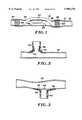
- FIGS. 17 and 18are side sectional views of a bypass graft and system for securing the graft to a vessel wall, in accordance with the present invention.
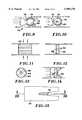
- FIGS. 19 and 20illustrate tissue dilators of alternative embodiment deployment systems employing thermal bonding
- FIG. 21is a schematic illustration of a circuit for thermal bonding
- FIGS. 22-25illustrate alternative embodiment dilators
- FIG. 26illustrates a tissue perforating needle used with the dilators of the various deployment systems
- FIG. 27is a sectional view of a needle and dilator contained within a catheter
- FIG. 28illustrates an alternative embodiment dilator within a catheter
- FIGS. 29a-hillustrate a series of steps of a percutaneous deployment and fixation of a bypass graft according to the present invention
- FIGS. 30a-dillustrate an alternative deployment and fixation procedure
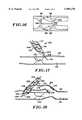
- FIGS. 31a-cillustrate a further alternative deployment and fixation
- FIG. 32shows several bypass grafts secured to the heart
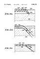
- FIGS. 33 and 34illustrate an alternative graft secured within a vessel.
- bypass graft 16secured within a blood vessel 18, in a manner to bypass a lesion 20 within the vessel.
- Bypass graft 16has a tubular wall 22 formed of a graft material, e.g., a polymer such as PTFE, urethane, polyimide, nylon, silicone, or polyethylene.
- the polymermay be extruded, blow molded, or dipped, and formed either directly into a tubing, or formed first as a sheet having opposed ends or edges bonded together to provide the tubular configuration.
- the edge bondcan be formed by a variety of methods including ultrasonic welding, thermal bonding, sewing, adhesives, or with radio frequency (RF) energy.
- the graftcan be a saphenous vein or other vessel from the patient.
- bypass graft 16incorporates a radially expandable stent 26.
- the graftincorporates a similar stent 28 at its distal end region 30.
- the stentsare radially expanded using a dilatation balloon or a mechanism such as those described in co-pending patent application Ser. No. 08/911,838 entitled “Mechanical Stent and Graft Delivery System,” filed Aug. 15, 1997.
- the graft end regionscan have a self-expanding structure, as described in co-pending patent application Ser. No. 08/932,566 entitled “Radially Expanding Prostheses and Systems for Their Deployment,” filed Sep. 19, 1997. In either event, each stent and its surrounding graft material are expanded into intimate contact with wall 22 of vessel 18, thus to secure the graft.
- graft 16bypasses lesion 20, in the sense that a medial region 32 of the graft is disposed outside of vessel 18.
- the graftcan be considered to exit the vessel at an exit opening or orifice 34 through vessel wall 35, and re-enter the vessel at a return opening or orifice 36.
- FIG. 2illustrates an annular collet 38 attached to one end of a graft 40.
- the colletmay be laminated or bonded to the graft, and is pre-formed to have a segment 42 extending radially beyond the graft. Segment 42 also is collapsible into a low profile to facilitate introduction through vasculature and deployment through the vessel wall. When released, the collet assumes the pre-formed configuration as shown.
- a portion 44 of the graftmay extend along collet segment 42 to secure the vessel wall between the graft material and the collet and provide additional support for attaching the graft to the vessel.
- FIGS. 3 and 4illustrate a collet 46 in which the radially extending collet segment is comprised of eight radially extended collet members 48.
- a membrane 50may be joined to the collet members to prevent fluid flow through the tissue wall puncture site.
- FIG. 5shows a further alternative support mechanism in the form of an annular grommet 52 secured to end region 54 of a graft 56.
- the grommetincorporates a convergence 58 to facilitate insertion through a vessel wall orifice, and a necked down feature 60 to capture the vessel wall immediately about the orifice.
- flexible bands 62can be fixed to an end region of a graft 64 as shown in FIGS. 6 and 7.
- Each band or other flexible memberis compressible into the reduced profile shown in FIG. 6 and remains in that profile while constrained, e.g., by a surrounding catheter.
- band 62assumes the radially enlarged, more circular profile shown in FIG. 7.
- Pluralities of such bandscan be provided in crossing patterns at the graft ends, if desired.
- the graftcan incorporate structural support members 66.
- the support memberscan be constructed of metal or a polymer having a higher modulus of elasticity than the graft material. As shown in FIG. 8, support members 66 can be distributed throughout the graft, with a greater density at the graft end regions to enhance fixation within openings through tissue. Support members 66 can have elliptical or rectangular profiles that enhance their strength in a selected direction.
- support memberscan be used in lieu of stents 26 and 28 for securing graft ends within a vessel.
- the support membersmay be laminated in the graft material. Fabrication can involve extruding or dipping an initial graft layer, winding the support members on the layer, then extruding or dipping to form a second layer covering the support members. Alternatively, the separate layers may be bonded together, or support members may be threaded through the graft material.
- thermal bondingmay be employed to augment the mechanical fixation and form a more positive fluid seal.
- electrode strips 68are mounted to the graft near the graft ends, and coupled through wires 70 to an energy source (e.g., an RF generator) which generates a current to heat adjacent tissue.
- an energy sourcee.g., an RF generator
- the graft edgesare thermally secured to the vessel wall by a coagulation of the tissue to the electrode, or by desiccation of the vessel wall to provide an interference fit between the reduced-diameter vessel and the graft, especially where the graft and support members exert a radial force. This better secures the graft to the vessel wall and prevents leaks at the graft edges.
- Suitable materials for the electrodeswhich are body compatible as well as electrically conductive, are platinum, platinum-iridium, stainless steel, and gold.
- signal wires 70are removed from the graft by delivering a D.C. current through the signal wires at an amplitude sufficient to cause a breakdown of the signal wire, e.g., at a reduced-diameter weak point near its associated electrode.
- the signal wirecan be cleaved, or mechanically removed by applying tension to sever the wire at a reduced-diameter neck region.
- FIGS. 9-16show a variety of graft constructions.
- a valve 72includes a valve ball 74 within a surrounding structure that provides a valve seat 76 on one side of the ball, and upper and lower retainers 78 and 80 on the other side of the ball.
- the valveis open and allows flow in the direction of the arrows, around the valve ball and through open spaces between the valve ball and surrounding structure in the area not occupied by the upper and lower retainers.
- valvefunctions as a pressure relief valve in that the flow from left to right as viewed in the figure must be sufficient to overcome the tendency of retainers 78 and 80 to urge the ball valve against the valve seat.
- FIG. 11shows a valve 82 designed to react to the muscular contraction to restore normal vessel function. Muscular contraction forces the valve ends inward, opening the valve to permit fluid flow.
- the force required to open the valvemay be selected, depending on the material, wall thickness, length, and geometry.
- a solid valverequires more force than a valve in which material is selectively removed to maintain the valve function yet decrease the required compressive force to open the valve.
- FIGS. 12-14show a one-way valve 84 having a membrane 86 that closes over valve support struts 88 when no external pressure is present.
- membrane 86distends outwardly away from the struts as seen in FIG. 14, permitting the flow of fluids. Fluid flow in the opposite direction (right to left as viewed in FIGS. 12 and 14) is prevented.
- FIGS. 9-10 and 12-14act as pressure relief valves, in the sense that they may be tailored to require a selected force to open them, and they remain open only when the applied pressure exceeds the valve resistance. As a result, these valves characteristically remain open for short periods of time.
- FIGS. 15 and 16show a pressure relief valve 90 that opens due to pressure exerted on the valve, and remains open until a compressive closure force is applied.
- Valve 90includes a plunger 92 movable within a surrounding structure including a valve seat 94 and a knob structure 96 for retaining the valve against the valve seat.
- the outer structurewhich can be the graft itself, includes a flexible section 98 including a protrusion 100 that can be flexed radially inwardly responsive to external pressure.
- the knob structuremaintains the valve closed until pressure against the valve, i.e., acting from left to right as viewed in FIG. 16, exceeds a selected threshold and opens the valve to allow rightward flow. Even after such pressure subsides, the valve remains open until external, radially inward pressure is applied to compress flexible section 98 of the graft. This moves the plunger leftward, returning it beyond the knob structure against the valve seat, thus closing the valve once again.
- Valve 90is particularly well-suited for treating urinary incontinence.
- bladder pressureexceeds the relief valve pressure threshold, the valve is opened to permit the flow of urine.
- muscular contractions or other external squeezingflexes section 98 to return plunger 92 to the valve seat, thus closing the valve.
- Systems for deploying graftsmay require an incision, or alternatively may involve translumenal delivery for a substantially noninvasive procedure.
- the systemmust restrain the graft during introduction through sheathes positioned via the Seldinger technique or a surgical cut-down, advancement through the vasculature and into the target vessel. Unwanted perforations of the vessel or other tissue must be avoided. This requires flexibility to follow a guide wire positioned in the target vessel. Further, the system must facilitate easy and accurate deployment of the graft and delivery components. If a partially deployed graft needs to be altered as to location, the system should permit recapture and repositioning.
- Graft delivery systemsmay incorporate the capacity to mechanically create intimate contact of the graft with surrounded tissue, especially at the graft ends. This capability is discussed in the aforementioned application Ser. No. 08/911,838 entitled “Mechanical Stent and Graft Delivery System.”
- FIGS. 17 and 18show a bypass graft deployment system 102 that requires an incision.
- the systemincludes a dilator 104 having a tapered (distally converging) distal tip 106.
- a needle 108is mounted coaxially within the dilator, and has a sharp cutting edge 110 for puncturing or perforating tissue.
- a bypass graft 112, having a grommet 114 or other suitable fixation mechanism,is supported on and surrounds the dilator.
- Needle 108which can be slideably contained within the dilator if desired, is introduced into the insertion port and punctures a wall 116 of a vessel 118 on one side of a stenosed lesion 120.
- the dilatorthen is advanced over the needle to enlarge the puncture to provide an orifice for fixation of the graft.
- graft 112is advanced over the dilator sufficiently to position grommet 114 within the orifice.
- a first region 122 of the graftis secured, so that an opening 124 of the graft is in fluid communication with vessel 118.
- graft 112has two further openings: an opening 126 surrounded by graft material and a second grommet 128; and a more proximally disposed opening 130, where no grommet or other fixation device is provided.
- the dilator and needleare withdrawn from opening 126, and further are withdrawn from a region 132 of the graft surrounding opening 130 so that the dilator and needle are completely free of the graft. Then opening 130, which is provided only to allow access of the dilator and needle, is closed to prevent fluid leakage from the graft.
- One suitable closure mechanismis a purse-string, formed by threading a suture through the graft material in region 132.
- Other closure mechanismsinclude staples or adhesives.
- the bypass graftmay have four or more openings to accommodate three or more fluid couplings to vasculature or organ cavities.
- FIG. 19shows a dilator 136 with a central lumen 138 for a needle (needle not shown).
- the dilatoralso incorporates a lumen 140, through which a signal wire can extend for coupling with a dilator electrode 142.
- Electrode 142delivers RF energy to a grommet 144 at the distal end of a graft 146 surrounding the dilator, thus to thermally secure the grommet to a tissue wall 148 of a vessel 150.
- a dilator 152includes, along with a central needle lumen 154, a signal wire lumen 156 and a balloon inflation lumen 158 open to a balloon 160 near the distal end of the dilator.
- the dilatorsupports a surrounding graft 162 having a collet 164 at its distal end.
- balloon 160is inflated to temporarily secure the dilator, which also bends a portion of collet 164 into the retaining position as shown.
- An electrode 170mounted on the exterior of balloon 160, receives a current from a signal wire contained in lumen 156, for thermally bonding collet 164 to the surrounding tissue. After thermal bonding, the balloon is deflated and the dilator withdrawn.
- FIG. 21illustrates a schematic circuit for ohmic heating of tissue, usable in conjunction with electrode 170, other dilator supported electrodes, or electrodes mounted directly to a graft as previously described.
- An RF power generator 174is coupled to the electrode through a signal wire 176.
- An indifferent electrode 178spaced apart from electrode 170 and typically placed on a patient externally, is coupled to the RF generator through a conductor 180. Thus, a current is generated through tissue between electrodes 170 and 178, heating the tissue to form the bond.
- FIGS. 22 and 23are sectional views of a distal region of a dilator 182, taken at different angles to show different lumens through the dilator.
- Lumens 184 and 186 in FIG. 22accommodate signal wires to sensors or transducers 188 and 190 (further discussed below), which can be used to direct placement of the dilator at puncture sites.
- Sensor 188is positioned for axial sensing, while a sensor 190 is oriented for lateral sensing.
- Several sensors 190can be angularly spaced apart from one another about the dilator circumference.
- Lumens 192 and 194, shown in FIG. 23,accommodate signal wires 196 to electrodes 198 used for thermal bonding.
- a steering mechanismcan be incorporated into the dilator to facilitate positioning of the dilator and needle for tissue perforations.
- a ring 198is embedded in the dilator distal tip, surrounding needle lumen 200.
- a wire 202is attached to ring 198. By pulling wire 202, the distal tip can be biased downwardly as viewed in the figure.
- magnetsmay be incorporated into the dilator near its distal tip, as indicated at 206 for a dilator 208 shown in FIG. 25.
- Such magnetsmay be formed of ferrite materials, or alternatively may be formed by winding conductive coils around the dilator to form electromagnets when current is supplied.
- the dilator magnetsare used in conjunction with a guide wire 209 advanced beyond a stenosed lesion 210 within a vessel 212.
- the guide wireis formed of metal, and to further enhance magnetic attraction may incorporate a magnet 214 of opposite polarity to the dilator magnet. Magnetic positioning facilitates placing bypass grafts through tortuous vessels or over long distances beyond the lesion. Alternatively, known imaging techniques can be used to locate the dilator magnets.
- a needlealso can be provided with steering capability, in particular by forming a hollow needle 216 and securing a wire 218 to a distal portion of a needle through a weld or solder joint 220.
- a sensor 222 at the needle tip, coupled to wires 224 contained within the needle lumen,can be used to sense a position of the needle tip.
- a further needle enhancementis a stop 226. When open as shown in FIG. 26, stop 226 limits the degree to which needle 216 can be inserted into tissue, thus preventing excessive, damaging perforations. At the same time, stop 226 is collapsible into a diameter substantially the same as that of the needle when the needle is withdrawn into a dilator.
- Intralumenal graft deployment systemsalso utilize dilators and needles as described, but further incorporate catheters.
- a suitable arrangementas shown in FIG. 27, includes a needle 228 surrounded by a dilator 230, which in turn is surrounded by a catheter 232, all components being coaxial and circular in profile.
- FIG. 28incorporates non-circular features into a dilator 234 and a lumen of a catheter 236.
- the non-circular matching featuresallow transmittal of torque from catheter 236 to dilator 234, enabling selective rotation of the dilator by rotating the catheter.
- FIGS. 29a-29hillustrate progressive steps in a percutaneous, intralumenal deployment of a graft 238, to bypass a lesion in a vessel 240.
- the systemincludes a catheter 242 with a lumen 244 containing graft 238, a dilator 246 and a needle 248 within the dilator.
- the catheter and other componentsare advanced intralumenally to the proximal side of lesion 250 as shown in FIG. 29a.
- Sensors 252facilitate positioning.
- Such sensorscan include ultrasonic transducers of piezoelectric material, infrared transducers, or fiber-optic elements.
- a radiopaque contrast materialmay be injected to enhance fluoroscopic visualization.
- needle 248is advanced to puncture vessel wall 254.
- a stop 256restricts movement of a needle if necessary.
- dilator 246is advanced, collapsing stop 256 and enlarging the puncture to provide a suitable orifice through the vessel wall.
- the orifice and dilatortend to form a seal, preventing excess blood leakage as the dilator is advanced along and outside of the vessel.
- the dilatormay have a pre-shaped distal end to facilitate positioning, as shown in FIG. 29c.
- needle 248is advanced beyond the dilator to puncture vessel wall 254 (FIG. 29d).
- stop 256prevents excessive needle advancement, if necessary.
- the stopcan limit needle travel relative to the dilator.
- dilator 246is advanced over the needle (FIG. 29e), collapsing the stop and enlarging the puncture by its distal tip, entering the vessel once again.
- needle 248may be completely retracted if desired.
- graft 238then is advanced over dilator 246, until the graft re-enters the vessel, i.e., has its opposite ends contained, each in its respective orifice.
- a collet 258 at the distal end of the graftprevents graft retraction, and a collet 260 anchors the proximal end of the graft.
- the dilatorcan be retracted back into catheter 242, as shown in FIG. 29g.
- a hollow stylet 262is used to advance the graft, and also to maintain the graft in place during subsequent withdrawal of the dilator.
- the catheter, stylet and dilatorare withdrawn, leaving graft 238 secured, as seen in FIG. 29h.
- FIGS. 30a-dshow an alternative system and graft deployment process, in which a graft 264 is guided to its bypass location within a catheter rather than over a dilator.
- the systemincludes a catheter 266 containing a dilator 268, which in turn contains a puncturing needle 270. These components are advanced to a position proximate a lesion 272 within a vessel 274. Dilator 268 is pre-formed with a bend at its distal region, and when positioned as shown in FIG. 30a, is directed upwardly toward the vessel wall as shown, to direct the needle toward the first intended puncture.
- dilator 268can be advanced over the needle, outside of and along the vessel.
- the dilatoris rotated, preferably by the catheter using non-circular profile features as described above, to reorient the tip and point it back toward the vessel as shown in FIG. 30b.
- Catheter 266is advanced along the dilator, through the orifice and outside of the vessel.
- a balloon 276 surrounding the cathetercan be inflated at this point, to maintain the catheter against proximal withdrawal.
- needle 270is advanced to form the puncture for a re-entry orifice (FIG. 30c).
- the dilator tipis used to enlarge the orifice, permitting advancement of the dilator into vessel 274, followed by advancement of catheter 266 over the dilator, through the orifice and into the vessel as well.
- Balloon 276can be reinflated at this point, to temporarily secure the catheter.
- a graftcan be inserted into the catheter and moved distally along the catheter using a stylet 278, until the graft reaches a bypass location in which each end of the graft is contained within its respective orifice.
- Withdrawal of the catheter(not shown), while the stylet maintains the graft in the bypass location, allows collets or other fixation mechanisms to expand and secure the graft.
- This procedureis particularly suited for smaller lesions, where the dilator need travel only a short distance along the vessel.
- FIGS. 31a-cillustrate a further alternative system and procedure for forming a bypass from a vessel to an organ cavity.
- a catheter 280 containing a dilator 282 and a needle 284is advanced to an intended puncture site 286 within a vessel 288.
- the punctureis formed as previously described, and the dilator is advanced through tissue to an organ cavity 290.
- the catheteris advanced over the dilator, becoming open to the cavity as shown in FIG. 31b.
- Collets 293 and 295secure the catheter.
- a valve 296 within the catheterlimits flow to the direction indicated by the arrow.
- a graft 298 incorporating a valve 300is positioned near lesion 302, to prevent backflow toward the lesion.
- FIG. 32illustrates two bypass grafts 304 and 306 used to couple the aorta to coronary vasculature in accordance with the present invention.
- FIG. 33illustrates a graft 306 collapsed around a catheter body 308, deployed in a target vessel across a stenosed lesion 310.
- the catheter and graftare translumenally advanced to the position shown.
- the opposite ends of the graftcontain expandable stents 314 and 316, expanded in place with a mechanism such as those described in the aforementioned application Ser. No. 08/911,838.
- the graft endscan have self-expanding characteristics.
- FIG. 34shows the graft expanded.
- the endsare fully expanded into intimate contact with the vessel wall.
- graft 306is expanded only to a nominal diameter.
- the diameteris selected to reduce the flow of resistance and increase cardiac output, yet prevent damage to the endothelial wall. For example, a 50% expansion usually is sufficient to open the vessel while preventing excess damage.
- a large space between the exterior of the graft and the vessel wallaccommodates growth of the stenosed lesion, and tends to contain such growth along the vessel wall so that the vessel remains open.
- graft 308should have inherent radial stability, for example, by employing structural supports as previously discussed.
- graft structural stability and fixationcan be enhanced by forming grafts with two or more layers, with pockets formed between the layers to contain biocompatible foams which solidify when activated to provide further support. Drug solutions also can be provided in such pockets.
- channelsmay be formed through the lesion by cutting a slit through the vessel wall in the targeted region.
- a mechanical deployment system as described in the aforementioned patent application Ser. No. 08/911,838can be used to form the required channel.
- a more easily deployed graftis more reliably secured, to effectively bypass lesions and other blockages.
Landscapes
- Health & Medical Sciences (AREA)
- Life Sciences & Earth Sciences (AREA)
- Veterinary Medicine (AREA)
- Public Health (AREA)
- Engineering & Computer Science (AREA)
- Biomedical Technology (AREA)
- Heart & Thoracic Surgery (AREA)
- Animal Behavior & Ethology (AREA)
- General Health & Medical Sciences (AREA)
- Cardiology (AREA)
- Vascular Medicine (AREA)
- Oral & Maxillofacial Surgery (AREA)
- Surgery (AREA)
- Transplantation (AREA)
- Gastroenterology & Hepatology (AREA)
- Nuclear Medicine, Radiotherapy & Molecular Imaging (AREA)
- Pulmonology (AREA)
- Medical Informatics (AREA)
- Molecular Biology (AREA)
- Prostheses (AREA)
- Media Introduction/Drainage Providing Device (AREA)
- Surgical Instruments (AREA)
- Pharmaceuticals Containing Other Organic And Inorganic Compounds (AREA)
- Medicines That Contain Protein Lipid Enzymes And Other Medicines (AREA)
Abstract
Description
Claims (35)
Priority Applications (7)
| Application Number | Priority Date | Filing Date | Title |
|---|---|---|---|
| US08/966,003US5989276A (en) | 1996-11-08 | 1997-11-07 | Percutaneous bypass graft and securing system |
| US09/415,776US6293955B1 (en) | 1996-09-20 | 1999-10-08 | Percutaneous bypass graft and securing system |
| US09/903,219US20010051809A1 (en) | 1996-11-08 | 2001-07-10 | Percutaneous bypass graft and securing system |
| US09/991,455US6652544B2 (en) | 1996-11-08 | 2001-11-21 | Percutaneous bypass graft and securing system |
| US10/243,488US20030014063A1 (en) | 1996-11-08 | 2002-09-12 | Percutaneous bypass graft and securing system |
| US10/243,325US20030014062A1 (en) | 1996-11-08 | 2002-09-12 | Percutaneous bypass graft and securing system |
| US10/243,260US7083631B2 (en) | 1996-11-08 | 2002-09-12 | Percutaneous bypass graft and securing system |
Applications Claiming Priority (2)
| Application Number | Priority Date | Filing Date | Title |
|---|---|---|---|
| US3073396P | 1996-11-08 | 1996-11-08 | |
| US08/966,003US5989276A (en) | 1996-11-08 | 1997-11-07 | Percutaneous bypass graft and securing system |
Related Child Applications (3)
| Application Number | Title | Priority Date | Filing Date |
|---|---|---|---|
| US08/932,566ContinuationUS6149681A (en) | 1996-09-20 | 1997-09-19 | Radially expanding prostheses and systems for their deployment |
| US09/415,776ContinuationUS6293955B1 (en) | 1996-09-20 | 1999-10-08 | Percutaneous bypass graft and securing system |
| US09/903,219ContinuationUS20010051809A1 (en) | 1996-11-08 | 2001-07-10 | Percutaneous bypass graft and securing system |
Publications (1)
| Publication Number | Publication Date |
|---|---|
| US5989276Atrue US5989276A (en) | 1999-11-23 |
Family
ID=21855718
Family Applications (6)
| Application Number | Title | Priority Date | Filing Date |
|---|---|---|---|
| US08/966,003Expired - Fee RelatedUS5989276A (en) | 1996-09-20 | 1997-11-07 | Percutaneous bypass graft and securing system |
| US09/903,219AbandonedUS20010051809A1 (en) | 1996-11-08 | 2001-07-10 | Percutaneous bypass graft and securing system |
| US09/991,455Expired - Fee RelatedUS6652544B2 (en) | 1996-11-08 | 2001-11-21 | Percutaneous bypass graft and securing system |
| US10/243,488AbandonedUS20030014063A1 (en) | 1996-11-08 | 2002-09-12 | Percutaneous bypass graft and securing system |
| US10/243,325AbandonedUS20030014062A1 (en) | 1996-11-08 | 2002-09-12 | Percutaneous bypass graft and securing system |
| US10/243,260Expired - Fee RelatedUS7083631B2 (en) | 1996-11-08 | 2002-09-12 | Percutaneous bypass graft and securing system |
Family Applications After (5)
| Application Number | Title | Priority Date | Filing Date |
|---|---|---|---|
| US09/903,219AbandonedUS20010051809A1 (en) | 1996-11-08 | 2001-07-10 | Percutaneous bypass graft and securing system |
| US09/991,455Expired - Fee RelatedUS6652544B2 (en) | 1996-11-08 | 2001-11-21 | Percutaneous bypass graft and securing system |
| US10/243,488AbandonedUS20030014063A1 (en) | 1996-11-08 | 2002-09-12 | Percutaneous bypass graft and securing system |
| US10/243,325AbandonedUS20030014062A1 (en) | 1996-11-08 | 2002-09-12 | Percutaneous bypass graft and securing system |
| US10/243,260Expired - Fee RelatedUS7083631B2 (en) | 1996-11-08 | 2002-09-12 | Percutaneous bypass graft and securing system |
Country Status (5)
| Country | Link |
|---|---|
| US (6) | US5989276A (en) |
| EP (1) | EP1011458A2 (en) |
| JP (1) | JP2001503657A (en) |
| AU (1) | AU721415B2 (en) |
| WO (1) | WO1998019625A2 (en) |
Cited By (167)
| Publication number | Priority date | Publication date | Assignee | Title |
|---|---|---|---|---|
| US6241741B1 (en) | 1998-03-09 | 2001-06-05 | Corvascular Surgical Systems, Inc. | Anastomosis device and method |
| US6254564B1 (en) | 1998-09-10 | 2001-07-03 | Percardia, Inc. | Left ventricular conduit with blood vessel graft |
| US6253768B1 (en) | 1999-08-04 | 2001-07-03 | Percardia, Inc. | Vascular graft bypass |
| US6264662B1 (en)* | 1998-07-21 | 2001-07-24 | Sulzer Vascutek Ltd. | Insertion aid for a bifurcated prosthesis |
| WO2001039672A3 (en)* | 1999-11-30 | 2002-01-17 | St Jude Medical Cardiovascular | Medical grafting methods and apparatus |
| WO2001070133A3 (en)* | 2000-03-20 | 2002-02-28 | Jan Otto Solem | Method and system for bypassing an artery block |
| US6361559B1 (en) | 1998-06-10 | 2002-03-26 | Converge Medical, Inc. | Thermal securing anastomosis systems |
| US20020173809A1 (en)* | 1999-09-01 | 2002-11-21 | Fleischman Sidney D. | Sutureless anastomosis system deployment concepts |
| US6485513B1 (en)* | 1999-10-08 | 2002-11-26 | The General Hospital Corporation | Percutaneous stent graft and method for vascular bypass |
| US20020183769A1 (en)* | 2001-05-30 | 2002-12-05 | St. Jude Medical Atg, Inc. | Medical grafting methods and apparatus |
| US6494889B1 (en) | 1999-09-01 | 2002-12-17 | Converge Medical, Inc. | Additional sutureless anastomosis embodiments |
| US20030014062A1 (en)* | 1996-11-08 | 2003-01-16 | Houser Russell A. | Percutaneous bypass graft and securing system |
| US6517558B2 (en) | 1999-01-15 | 2003-02-11 | Ventrica, Inc. | Methods and devices for forming vascular anastomoses |
| US20030093095A1 (en)* | 2001-07-05 | 2003-05-15 | Whayne James G. | Distal anastomosis system |
| US20030109828A1 (en)* | 2001-10-22 | 2003-06-12 | Oleg Shikhman | Removable sleeve |
| US20030130671A1 (en)* | 1999-11-23 | 2003-07-10 | Duhaylongsod Francis G. | Anastomosis device and method |
| US6605053B1 (en) | 1999-09-10 | 2003-08-12 | Percardia, Inc. | Conduit designs and related methods for optimal flow control |
| US20030167064A1 (en)* | 1999-09-01 | 2003-09-04 | Whayne James G. | Advanced anastomosis systems (II) |
| US6626920B2 (en) | 2001-07-05 | 2003-09-30 | Converge Medical, Inc. | Distal anastomosis system |
| US6635214B2 (en) | 1999-09-10 | 2003-10-21 | Ventrica, Inc. | Manufacturing conduits for use in placing a target vessel in fluid communication with a source of blood |
| US20030220682A1 (en)* | 2002-05-22 | 2003-11-27 | Dennis Kujawski | Stent with segmented graft |
| US20030229365A1 (en)* | 2002-06-10 | 2003-12-11 | Whayne James G. | Angled vascular anastomosis system |
| US20040034406A1 (en)* | 2002-08-19 | 2004-02-19 | Thramann Jeffrey J. | Vascular stent grafts |
| US6694983B2 (en) | 1998-09-10 | 2004-02-24 | Percardia, Inc. | Delivery methods for left ventricular conduit |
| US6695859B1 (en) | 1999-04-05 | 2004-02-24 | Coalescent Surgical, Inc. | Apparatus and methods for anastomosis |
| US6699256B1 (en)* | 1999-06-04 | 2004-03-02 | St. Jude Medical Atg, Inc. | Medical grafting apparatus and methods |
| US20040050393A1 (en)* | 2002-09-12 | 2004-03-18 | Steve Golden | Anastomosis apparatus and methods |
| US20040068278A1 (en)* | 1999-12-06 | 2004-04-08 | Converge Medical Inc. | Anastomosis systems |
| US6726694B2 (en)* | 1999-04-16 | 2004-04-27 | Integrated Vascular Interventional Technologies, L.C. (Ivit, Lc) | Intraluminally directed anvil apparatus and related methods and systems |
| US20040113306A1 (en)* | 1999-05-19 | 2004-06-17 | Rapacki Alan R | Manufacturing conduits for use in placing a target vessel in fluid communication with a source of blood |
| US20040181273A1 (en)* | 2003-03-10 | 2004-09-16 | Evan Brasington | Dilator with expandable member |
| US6808498B2 (en) | 1998-02-13 | 2004-10-26 | Ventrica, Inc. | Placing a guide member into a heart chamber through a coronary vessel and delivering devices for placing the coronary vessel in communication with the heart chamber |
| US20040225233A1 (en)* | 2003-05-09 | 2004-11-11 | Frankowski Brian J. | Magnetic guidewires |
| US20050004585A1 (en)* | 1998-10-02 | 2005-01-06 | Hall Andrew F. | Magnetically navigable and/or controllable device for removing material from body lumens and cavities |
| WO2004016195A3 (en)* | 2002-08-19 | 2005-01-27 | Jeffrey J M D Thramann | Vascular stent grafts |
| US6858035B2 (en) | 2001-07-05 | 2005-02-22 | Converge Medical, Inc. | Distal anastomosis system |
| US20050060020A1 (en)* | 2003-09-17 | 2005-03-17 | Scimed Life Systems, Inc. | Covered stent with biologically active material |
| US20050154444A1 (en)* | 2003-10-10 | 2005-07-14 | Arshad Quadri | System and method for endoluminal grafting of bifurcated and branched vessels |
| US6960219B2 (en)* | 1999-03-09 | 2005-11-01 | St. Jude Medical Atg, Inc. | Medical grafting methods and apparatus |
| US6962595B1 (en) | 2002-01-22 | 2005-11-08 | Cardica, Inc. | Integrated anastomosis system |
| US20050251163A1 (en)* | 2001-07-05 | 2005-11-10 | Converge Medical, Inc. | Vascular anastomosis systems |
| US20050273159A1 (en)* | 2004-01-22 | 2005-12-08 | Opie John C | Monocusp valve construction and defect closure device for deep vein regurgitation |
| US20060069401A1 (en)* | 2004-09-27 | 2006-03-30 | Wright David W | Fastener apparatus for tissue and methods of deployment and manufacture |
| US7025773B2 (en) | 1999-01-15 | 2006-04-11 | Medtronic, Inc. | Methods and devices for placing a conduit in fluid communication with a target vessel |
| US20060142791A1 (en)* | 1998-03-09 | 2006-06-29 | Chapman Troy J | Anastomosis device and method |
| US20060276883A1 (en)* | 2005-06-01 | 2006-12-07 | Cook Incorporated | Tapered and distally stented elephant trunk stent graft |
| US7182771B1 (en) | 2001-12-20 | 2007-02-27 | Russell A. Houser | Vascular couplers, techniques, methods, and accessories |
| US7223274B2 (en) | 2002-01-23 | 2007-05-29 | Cardica, Inc. | Method of performing anastomosis |
| US20070123964A1 (en)* | 2003-01-21 | 2007-05-31 | Baylis Medical Company | Magnetically guidable energy delivery apparatus and method of using same |
| US20080045984A1 (en)* | 1999-04-16 | 2008-02-21 | Integrated Vascular Interventional Technologies, L.C. | Methods for anastomosing an everted vessel with another vessel |
| US7335216B2 (en) | 2002-01-22 | 2008-02-26 | Cardica, Inc. | Tool for creating an opening in tissue |
| US20080109058A1 (en)* | 2005-06-01 | 2008-05-08 | Cook Incorporated | Intraoperative Anastomosis Method |
| US7462162B2 (en) | 2001-09-04 | 2008-12-09 | Broncus Technologies, Inc. | Antiproliferative devices for maintaining patency of surgically created channels in a body organ |
| WO2008115924A3 (en)* | 2007-03-20 | 2008-12-24 | Medtronic Vascular Inc | Helical screw puncture tip |
| US20090125100A1 (en)* | 2007-11-13 | 2009-05-14 | Cook Incorporated | Intraluminal Bypass Prosthesis and Prosthesis Delivery and Deployment Kit |
| US7547313B2 (en) | 1998-06-03 | 2009-06-16 | Medtronic, Inc. | Tissue connector apparatus and methods |
| US7578828B2 (en) | 1999-01-15 | 2009-08-25 | Medtronic, Inc. | Methods and devices for placing a conduit in fluid communication with a target vessel |
| US7585306B2 (en) | 2003-12-24 | 2009-09-08 | Maquet Cardiovascular Llc | Anastomosis device, tools and methods of using |
| US20100023132A1 (en)* | 2008-07-28 | 2010-01-28 | Incube Laboratories LLC | System and method for scaffolding anastomoses |
| US7708712B2 (en) | 2001-09-04 | 2010-05-04 | Broncus Technologies, Inc. | Methods and devices for maintaining patency of surgically created channels in a body organ |
| US7722643B2 (en) | 1999-03-01 | 2010-05-25 | Medtronic, Inc. | Tissue connector apparatus and methods |
| US7744611B2 (en) | 2000-10-10 | 2010-06-29 | Medtronic, Inc. | Minimally invasive valve repair procedure and apparatus |
| US7763040B2 (en) | 1998-06-03 | 2010-07-27 | Medtronic, Inc. | Tissue connector apparatus and methods |
| US20100204776A1 (en)* | 2006-07-07 | 2010-08-12 | Graft Technologies, Inc., a Texas corporation | System and Method for Providing a Graft in a Vascular Environment |
| US7815590B2 (en) | 1999-08-05 | 2010-10-19 | Broncus Technologies, Inc. | Devices for maintaining patency of surgically created channels in tissue |
| US7879047B2 (en) | 2003-12-10 | 2011-02-01 | Medtronic, Inc. | Surgical connection apparatus and methods |
| US7896892B2 (en) | 2000-03-31 | 2011-03-01 | Medtronic, Inc. | Multiple bias surgical fastener |
| US7918870B2 (en) | 2005-09-12 | 2011-04-05 | Bridgepoint Medical, Inc. | Endovascular devices and methods |
| US7938819B2 (en) | 2005-09-12 | 2011-05-10 | Bridgepoint Medical, Inc. | Endovascular devices and methods |
| US7963973B2 (en) | 1998-06-03 | 2011-06-21 | Medtronic, Inc. | Multiple loop tissue connector apparatus and methods |
| US7993356B2 (en) | 1998-02-13 | 2011-08-09 | Medtronic, Inc. | Delivering a conduit into a heart wall to place a coronary vessel in communication with a heart chamber and removing tissue from the vessel or heart wall to facilitate such communication |
| US8002740B2 (en) | 2003-07-18 | 2011-08-23 | Broncus Technologies, Inc. | Devices for maintaining patency of surgically created channels in tissue |
| US8012164B1 (en) | 2002-01-22 | 2011-09-06 | Cardica, Inc. | Method and apparatus for creating an opening in the wall of a tubular vessel |
| US8029519B2 (en) | 2003-08-22 | 2011-10-04 | Medtronic, Inc. | Eversion apparatus and methods |
| US8034064B2 (en) | 1999-04-16 | 2011-10-11 | Vital Access Corporation | Methods for forming an anastomosis opening in a side of a blood vessel |
| US8083727B2 (en) | 2005-09-12 | 2011-12-27 | Bridgepoint Medical, Inc. | Endovascular devices and methods for exploiting intramural space |
| US8105345B2 (en) | 2002-10-04 | 2012-01-31 | Medtronic, Inc. | Anastomosis apparatus and methods |
| US8118822B2 (en) | 1999-03-01 | 2012-02-21 | Medtronic, Inc. | Bridge clip tissue connector apparatus and methods |
| US8162963B2 (en) | 2004-06-17 | 2012-04-24 | Maquet Cardiovascular Llc | Angled anastomosis device, tools and method of using |
| US8172863B2 (en) | 2008-04-28 | 2012-05-08 | Bridgepoint Medical, Inc. | Methods and apparatus for crossing occlusions in blood vessels |
| US8177836B2 (en) | 2008-03-10 | 2012-05-15 | Medtronic, Inc. | Apparatus and methods for minimally invasive valve repair |
| US20120143234A1 (en)* | 2010-02-26 | 2012-06-07 | Wilson Fletcher T | Systems and methods for endoluminal valve creation |
| US8202246B2 (en) | 2008-02-05 | 2012-06-19 | Bridgepoint Medical, Inc. | Crossing occlusions in blood vessels |
| US8211124B2 (en) | 2003-07-25 | 2012-07-03 | Medtronic, Inc. | Sealing clip, delivery systems, and methods |
| US8308682B2 (en) | 2003-07-18 | 2012-11-13 | Broncus Medical Inc. | Devices for maintaining patency of surgically created channels in tissue |
| US8323261B2 (en) | 2005-09-12 | 2012-12-04 | Bridgepoint Medical, Inc. | Methods of accessing an intramural space |
| US8337425B2 (en) | 2008-02-05 | 2012-12-25 | Bridgepoint Medical, Inc. | Endovascular device with a tissue piercing distal probe and associated methods |
| US8394114B2 (en) | 2003-09-26 | 2013-03-12 | Medtronic, Inc. | Surgical connection apparatus and methods |
| US8409167B2 (en) | 2004-07-19 | 2013-04-02 | Broncus Medical Inc | Devices for delivering substances through an extra-anatomic opening created in an airway |
| US8414635B2 (en) | 1999-02-01 | 2013-04-09 | Idev Technologies, Inc. | Plain woven stents |
| US8419788B2 (en) | 2006-10-22 | 2013-04-16 | Idev Technologies, Inc. | Secured strand end devices |
| US8512360B2 (en) | 1998-02-13 | 2013-08-20 | Medtronic, Inc. | Conduits for use in placing a target vessel in fluid communication with source of blood |
| US8518060B2 (en) | 2009-04-09 | 2013-08-27 | Medtronic, Inc. | Medical clip with radial tines, system and method of using same |
| US8529583B1 (en) | 1999-09-03 | 2013-09-10 | Medtronic, Inc. | Surgical clip removal apparatus |
| US8632556B2 (en) | 2007-10-22 | 2014-01-21 | Bridgepoint Medical, Inc. | Methods and devices for crossing chronic total occlusions |
| US8668704B2 (en) | 2009-04-24 | 2014-03-11 | Medtronic, Inc. | Medical clip with tines, system and method of using same |
| US8709034B2 (en) | 2011-05-13 | 2014-04-29 | Broncus Medical Inc. | Methods and devices for diagnosing, monitoring, or treating medical conditions through an opening through an airway wall |
| US8876881B2 (en) | 2006-10-22 | 2014-11-04 | Idev Technologies, Inc. | Devices for stent advancement |
| US20150094744A1 (en)* | 2012-05-25 | 2015-04-02 | H. Lee Moffitt Cancer Center And Research Institute, Inc. | Vascular anastomosis stent |
| US9023095B2 (en) | 2010-05-27 | 2015-05-05 | Idev Technologies, Inc. | Stent delivery system with pusher assembly |
| US20150134051A1 (en)* | 2012-08-16 | 2015-05-14 | Phraxis Inc. | Arterial and venous anchor devices forming an anastomotic connector and system for delivery |
| US9060802B2 (en) | 2006-11-21 | 2015-06-23 | Bridgepoint Medical, Inc. | Endovascular devices and methods for exploiting intramural space |
| US9345532B2 (en) | 2011-05-13 | 2016-05-24 | Broncus Medical Inc. | Methods and devices for ablation of tissue |
| US9827005B2 (en) | 2011-04-20 | 2017-11-28 | The Board Of Trustees Of The Leland Stanford Junior University | Systems and methods for endoluminal valve creation |
| US9955990B2 (en) | 2013-01-10 | 2018-05-01 | Intervene, Inc. | Systems and methods for endoluminal valve creation |
| US10105157B2 (en) | 2014-03-24 | 2018-10-23 | Intervene, Inc. | Devices, systems, and methods for controlled hydrodissection of vessel walls |
| US10231613B2 (en) | 2013-09-27 | 2019-03-19 | Intervene, Inc. | Visualization devices, systems, and methods for informing intravascular procedures on blood vessel valves |
| US10272260B2 (en) | 2011-11-23 | 2019-04-30 | Broncus Medical Inc. | Methods and devices for diagnosing, monitoring, or treating medical conditions through an opening through an airway wall |
| US10292807B2 (en) | 2012-02-07 | 2019-05-21 | Intervene, Inc. | Systems and methods for endoluminal valve creation |
| US10456239B2 (en) | 2011-06-15 | 2019-10-29 | Phraxis Inc. | Anastomotic connector and system for delivery |
| US10603018B2 (en) | 2014-12-16 | 2020-03-31 | Intervene, Inc. | Intravascular devices, systems, and methods for the controlled dissection of body lumens |
| US10646247B2 (en) | 2016-04-01 | 2020-05-12 | Intervene, Inc. | Intraluminal tissue modifying systems and associated devices and methods |
| US10751056B2 (en) | 2017-10-23 | 2020-08-25 | High Desert Radiology, P.C. | Methods and apparatus for percutaneous bypass graft |
| US10888354B2 (en) | 2006-11-21 | 2021-01-12 | Bridgepoint Medical, Inc. | Endovascular devices and methods for exploiting intramural space |
| US10993805B2 (en) | 2008-02-26 | 2021-05-04 | Jenavalve Technology, Inc. | Stent for the positioning and anchoring of a valvular prosthesis in an implantation site in the heart of a patient |
| US11020141B2 (en) | 2005-09-12 | 2021-06-01 | Bridgepoint Medical, Inc. | Endovascular devices and methods |
| US11065138B2 (en) | 2016-05-13 | 2021-07-20 | Jenavalve Technology, Inc. | Heart valve prosthesis delivery system and method for delivery of heart valve prosthesis with introducer sheath and loading system |
| US11185405B2 (en) | 2013-08-30 | 2021-11-30 | Jenavalve Technology, Inc. | Radially collapsible frame for a prosthetic valve and method for manufacturing such a frame |
| US11197754B2 (en) | 2017-01-27 | 2021-12-14 | Jenavalve Technology, Inc. | Heart valve mimicry |
| US11298511B2 (en) | 2006-11-21 | 2022-04-12 | Bridgepoint Medical, Inc. | Endovascular devices and methods for exploiting intramural space |
| US11337800B2 (en) | 2015-05-01 | 2022-05-24 | Jenavalve Technology, Inc. | Device and method with reduced pacemaker rate in heart valve replacement |
| US11357624B2 (en) | 2007-04-13 | 2022-06-14 | Jenavalve Technology, Inc. | Medical device for treating a heart valve insufficiency |
| US11464485B2 (en) | 2018-12-27 | 2022-10-11 | Avent, Inc. | Transducer-mounted needle assembly with improved electrical connection to power source |
| US11517431B2 (en) | 2005-01-20 | 2022-12-06 | Jenavalve Technology, Inc. | Catheter system for implantation of prosthetic heart valves |
| US11564794B2 (en) | 2008-02-26 | 2023-01-31 | Jenavalve Technology, Inc. | Stent for the positioning and anchoring of a valvular prosthesis in an implantation site in the heart of a patient |
| US11564797B2 (en) | 2015-08-25 | 2023-01-31 | Innovein, Inc. | Venous valve prosthesis |
| US11589981B2 (en) | 2010-05-25 | 2023-02-28 | Jenavalve Technology, Inc. | Prosthetic heart valve and transcatheter delivered endoprosthesis comprising a prosthetic heart valve and a stent |
| US11647980B2 (en) | 2018-12-27 | 2023-05-16 | Avent, Inc. | Methods for needle identification on an ultrasound display screen by determining a meta-frame rate of the data signals |
| US11660137B2 (en) | 2006-09-29 | 2023-05-30 | Boston Scientific Medical Device Limited | Connector system for electrosurgical device |
| US11684447B2 (en) | 2012-05-31 | 2023-06-27 | Boston Scientific Medical Device Limited | Radiofrequency perforation apparatus |
| US11724070B2 (en) | 2019-12-19 | 2023-08-15 | Boston Scientific Medical Device Limited | Methods for determining a position of a first medical device with respect to a second medical device, and related systems and medical devices |
| US11744638B2 (en) | 2006-09-29 | 2023-09-05 | Boston Scientific Medical Device Limited | Electrosurgical device |
| US11759190B2 (en) | 2019-10-18 | 2023-09-19 | Boston Scientific Medical Device Limited | Lock for medical devices, and related systems and methods |
| US11766290B2 (en) | 2015-09-09 | 2023-09-26 | Boston Scientific Medical Device Limited | Epicardial access system and methods |
| US11793446B2 (en) | 2020-06-17 | 2023-10-24 | Boston Scientific Medical Device Limited | Electroanatomical mapping system with visualization of energy-delivery and elongated needle assemblies |
| US11801087B2 (en) | 2019-11-13 | 2023-10-31 | Boston Scientific Medical Device Limited | Apparatus and methods for puncturing tissue |
| US11819243B2 (en) | 2020-03-19 | 2023-11-21 | Boston Scientific Medical Device Limited | Medical sheath and related systems and methods |
| US11826075B2 (en) | 2020-04-07 | 2023-11-28 | Boston Scientific Medical Device Limited | Elongated medical assembly |
| US11878131B2 (en) | 2017-12-05 | 2024-01-23 | Boston Scientific Medical Device Limited | Transseptal guide wire puncture system |
| US11931098B2 (en) | 2020-02-19 | 2024-03-19 | Boston Scientific Medical Device Limited | System and method for carrying out a medical procedure |
| US11937796B2 (en) | 2020-06-18 | 2024-03-26 | Boston Scientific Medical Device Limited | Tissue-spreader assembly |
| US11937873B2 (en) | 2013-03-12 | 2024-03-26 | Boston Scientific Medical Device Limited | Electrosurgical device having a lumen |
| US11938285B2 (en) | 2020-06-17 | 2024-03-26 | Boston Scientific Medical Device Limited | Stop-movement device for elongated medical assembly |
| US11980412B2 (en) | 2020-09-15 | 2024-05-14 | Boston Scientific Medical Device Limited | Elongated medical sheath |
| US11986209B2 (en) | 2020-02-25 | 2024-05-21 | Boston Scientific Medical Device Limited | Methods and devices for creation of communication between aorta and left atrium |
| US11992238B2 (en) | 2008-02-05 | 2024-05-28 | Boston Scientific Scimed, Inc. | Endovascular device with a tissue piercing distal probe and associated methods |
| US11998238B2 (en) | 2013-08-07 | 2024-06-04 | Boston Scientific Medical Device Limited | Methods and devices for puncturing tissue |
| US12005202B2 (en) | 2020-08-07 | 2024-06-11 | Boston Scientific Medical Device Limited | Catheter having tissue-engaging device |
| US12011210B2 (en) | 2013-03-15 | 2024-06-18 | Boston Scientific Medical Device Limited | Electrosurgical device having a distal aperture |
| US12011279B2 (en) | 2020-04-07 | 2024-06-18 | Boston Scientific Medical Device Limited | Electro-anatomic mapping system |
| US12042178B2 (en) | 2020-07-21 | 2024-07-23 | Boston Scientific Medical Device Limited | System of medical devices and method for pericardial puncture |
| US12082792B2 (en) | 2020-02-25 | 2024-09-10 | Boston Scientific Medical Device Limited | Systems and methods for creating a puncture between aorta and the left atrium |
| US12121461B2 (en) | 2015-03-20 | 2024-10-22 | Jenavalve Technology, Inc. | Heart valve prosthesis delivery system and method for delivery of heart valve prosthesis with introducer sheath |
| US12128199B2 (en) | 2016-01-07 | 2024-10-29 | Boston Scientific Medical Device Limited | Hybrid transseptal dilator and methods of using the same |
| US12156642B2 (en) | 2019-04-29 | 2024-12-03 | Boston Scientific Medical Device Limited | Transseptal systems, devices and methods |
| US12171658B2 (en) | 2022-11-09 | 2024-12-24 | Jenavalve Technology, Inc. | Catheter system for sequential deployment of an expandable implant |
| US12171622B2 (en) | 2017-08-10 | 2024-12-24 | Boston Scientific Medical Device Limited | Heat exchange and temperature sensing device and method of use |
| US12207836B2 (en) | 2016-11-01 | 2025-01-28 | Boston Scientific Medical Device Limited | Methods and devices for puncturing tissue |
| US12220543B2 (en) | 2020-09-10 | 2025-02-11 | Boston Scientific Medical Device Limited | Elongated medical catheter including marker band |
| US12251159B2 (en) | 2013-03-12 | 2025-03-18 | Boston Scientific Medical Device Limited | Medical device having a support structure |
| US12257401B2 (en) | 2013-12-20 | 2025-03-25 | Boston Scientific Medical Device Limited | Steerable medical device handle |
| US12343042B2 (en) | 2020-07-16 | 2025-07-01 | Boston Scientific Medical Device Limited | Pericardial puncture device and method |
| US12370354B2 (en) | 2018-05-08 | 2025-07-29 | Boston Scientific Medical Device Limited | Coupling mechanisms for medical devices |
| US12396785B2 (en) | 2020-08-12 | 2025-08-26 | Boston Scientific Medical Device Limited | System of medical devices and method for pericardial puncture |
| US12414854B2 (en) | 2010-05-20 | 2025-09-16 | Jenavalve Technology, Inc. | Catheter system for introducing an expandable stent into the body of a patient |
| US12420067B2 (en) | 2020-05-12 | 2025-09-23 | Boston Scientific Medical Device Limited | Guidewire assembly |
| US12440266B2 (en) | 2022-04-08 | 2025-10-14 | Boston Scientific Medical Device Limited | Transvascular electrosurgical devices and systems and methods of using the same |
Families Citing this family (117)
| Publication number | Priority date | Publication date | Assignee | Title |
|---|---|---|---|---|
| ATE440559T1 (en)* | 1995-10-13 | 2009-09-15 | Medtronic Vascular Inc | DEVICE FOR INTERSTITIAL TRANSVASCULAR PROCEDURES |
| AU733341B2 (en) | 1996-02-02 | 2001-05-10 | Transvascular, Inc. | A device, system and method for interstitial transvascular intervention |
| WO1998046115A2 (en) | 1997-04-11 | 1998-10-22 | Transvascular, Inc. | Methods and apparatus for transmyocardial direct coronary revascularization |
| US6193734B1 (en) | 1998-01-23 | 2001-02-27 | Heartport, Inc. | System for performing vascular anastomoses |
| US6352543B1 (en)* | 2000-04-29 | 2002-03-05 | Ventrica, Inc. | Methods for forming anastomoses using magnetic force |
| US6206913B1 (en) | 1998-08-12 | 2001-03-27 | Vascular Innovations, Inc. | Method and system for attaching a graft to a blood vessel |
| US6461320B1 (en)* | 1998-08-12 | 2002-10-08 | Cardica, Inc. | Method and system for attaching a graft to a blood vessel |
| US6641610B2 (en) | 1998-09-10 | 2003-11-04 | Percardia, Inc. | Valve designs for left ventricular conduits |
| US6475226B1 (en) | 1999-02-03 | 2002-11-05 | Scimed Life Systems, Inc. | Percutaneous bypass apparatus and method |
| AU5150600A (en) | 1999-05-18 | 2000-12-05 | Vascular Innovations, Inc. | Tissue punch |
| US6428550B1 (en)* | 1999-05-18 | 2002-08-06 | Cardica, Inc. | Sutureless closure and deployment system for connecting blood vessels |
| US6673088B1 (en) | 1999-05-18 | 2004-01-06 | Cardica, Inc. | Tissue punch |
| US7048751B2 (en) | 2001-12-06 | 2006-05-23 | Cardica, Inc. | Implantable medical device such as an anastomosis device |
| US7303570B2 (en) | 1999-07-28 | 2007-12-04 | Cardica, Inc. | Anastomosis tool having a connector holder |
| US7371243B1 (en) | 1999-07-28 | 2008-05-13 | Cardica, Inc. | Surgical apparatus and method for anastomosis |
| US7014644B1 (en) | 1999-07-28 | 2006-03-21 | Cardica, Inc. | Tissue bonding system and method for controlling a tissue site during anastomosis |
| US7300444B1 (en) | 1999-07-28 | 2007-11-27 | Cardica, Inc. | Surgical system and method for connecting hollow tissue structures |
| US7063712B2 (en) | 2001-04-27 | 2006-06-20 | Cardica, Inc. | Anastomosis method |
| US7285131B1 (en) | 1999-07-28 | 2007-10-23 | Cardica, Inc. | System for performing anastomosis |
| US6391038B2 (en) | 1999-07-28 | 2002-05-21 | Cardica, Inc. | Anastomosis system and method for controlling a tissue site |
| NL1014559C2 (en)* | 2000-02-11 | 2001-08-14 | Surgical Innovations Vof | Umbrella stent. |
| NL1014364C2 (en)* | 2000-02-11 | 2001-08-14 | Surgical Innovations Vof | Endoluminal grafting method for treating body conduit e.g. artery, aorta, involves introducing side graft into side branch through primary graft, afterwhich side graft is fixed to primary graft |
| US8518062B2 (en) | 2000-04-29 | 2013-08-27 | Medtronic, Inc. | Devices and methods for forming magnetic anastomoses between vessels |
| US20050080439A1 (en)* | 2000-04-29 | 2005-04-14 | Carson Dean F. | Devices and methods for forming magnetic anastomoses and ports in vessels |
| US7232449B2 (en) | 2000-04-29 | 2007-06-19 | Medtronic, Inc. | Components, systems and methods for forming anastomoses using magnetism or other coupling means |
| US6776785B1 (en) | 2000-10-12 | 2004-08-17 | Cardica, Inc. | Implantable superelastic anastomosis device |
| US6554764B1 (en) | 2000-11-13 | 2003-04-29 | Cardica, Inc. | Graft vessel preparation device and methods for using the same |
| US7909837B2 (en)* | 2000-12-13 | 2011-03-22 | Medtronic, Inc. | Methods, devices and systems for forming magnetic anastomoses |
| US20020143347A1 (en)* | 2000-12-13 | 2002-10-03 | Ventrica, Inc. | Extravascular anastomotic components and methods for forming vascular anastomoses |
| US20020095166A1 (en) | 2001-01-16 | 2002-07-18 | Jaime Vargas | Incision tensioning system and method for using the same |
| US6953464B2 (en)* | 2001-02-21 | 2005-10-11 | Novare Surgical Systems, Inc. | Anastomosis occlusion device |
| AU2003223672A1 (en)* | 2002-04-17 | 2003-11-03 | Tyco Healthcare Group Lp | Method and apparatus for anastomosis including an expandable anchor |
| US20040122362A1 (en)* | 2002-09-10 | 2004-06-24 | Houser Russell A. | Pseudo aneurysm repair system |
| US20040111143A1 (en)* | 2002-12-06 | 2004-06-10 | Fischell Robert E. | Introducer sheath for the ostial placement of a stent |
| US20050049675A1 (en)* | 2003-03-28 | 2005-03-03 | Board Of Regents, The University Of Texas System | Medical devices and related methods |
| EP1648280A4 (en)* | 2003-06-18 | 2007-08-15 | Univ Leland Stanford Junior | ELECTRO-ADHESIVE TISSUE MANIPULATOR |
| US20050149093A1 (en)* | 2003-10-30 | 2005-07-07 | Pokorney James L. | Valve bypass graft device, tools, and method |
| US7232440B2 (en) | 2003-11-17 | 2007-06-19 | Sherwood Services Ag | Bipolar forceps having monopolar extension |
| US12303105B2 (en) | 2004-04-12 | 2025-05-20 | Boston Scientific Scimed, Inc. | Luminal structure anchoring devices and methods |
| US20050228413A1 (en)* | 2004-04-12 | 2005-10-13 | Binmoeller Kenneth F | Automated transluminal tissue targeting and anchoring devices and methods |
| US8425539B2 (en)* | 2004-04-12 | 2013-04-23 | Xlumena, Inc. | Luminal structure anchoring devices and methods |
| EP1765451B1 (en)* | 2004-06-14 | 2021-11-17 | Edwards Lifesciences Corporation | Devices for arterio-venous fistula creation |
| US9138228B2 (en)* | 2004-08-11 | 2015-09-22 | Emory University | Vascular conduit device and system for implanting |
| US7641688B2 (en)* | 2004-09-16 | 2010-01-05 | Evera Medical, Inc. | Tissue augmentation device |
| JP5111112B2 (en)* | 2004-12-08 | 2012-12-26 | エックスルミナ, インコーポレイテッド | Device for performing needle-guided therapy |
| GB2423132A (en)* | 2005-02-15 | 2006-08-16 | Martin Lister | Ball heart valve |
| CN103190942A (en)* | 2005-05-12 | 2013-07-10 | 阿尔斯塔西斯公司 | Access and closure device and method |
| US9480589B2 (en)* | 2005-05-13 | 2016-11-01 | Boston Scientific Scimed, Inc. | Endoprosthesis delivery system |
| WO2006127412A1 (en)* | 2005-05-20 | 2006-11-30 | The Cleveland Clinic Foundation | Apparatus and methods for repairing the function of a diseased valve and method for making same |
| US8784437B2 (en)* | 2005-06-09 | 2014-07-22 | Xlumena, Inc. | Methods and devices for endosonography-guided fundoplexy |
| US8777967B2 (en)* | 2005-06-09 | 2014-07-15 | Xlumena, Inc. | Methods and devices for anchoring to tissue |
| WO2007016166A2 (en)* | 2005-07-27 | 2007-02-08 | Cook Critical Care Incorporated | Stent/graft device and method for open surgical placement |
| WO2007028112A2 (en)* | 2005-09-02 | 2007-03-08 | Medtronic Vascular, Inc. | Methods and apparatus for treatment of aneurysms adjacent to branch arteries |
| DE102005046333B3 (en)* | 2005-09-27 | 2006-10-19 | Viega Gmbh & Co. Kg | Press-tool for connecting pipes has jaws whose rear ends can overlap as they are opened, allowing them to be used on large diameter pipes |
| US20080039878A1 (en)* | 2006-07-06 | 2008-02-14 | Williams Michael S | Systems and methods for restoring function of diseased bowel |
| US10004584B2 (en) | 2006-07-10 | 2018-06-26 | First Quality Hygienic, Inc. | Resilient intravaginal device |
| WO2008008794A2 (en) | 2006-07-10 | 2008-01-17 | Mc Neil-Ppc, Inc. | Resilient device |
| US10219884B2 (en) | 2006-07-10 | 2019-03-05 | First Quality Hygienic, Inc. | Resilient device |
| US8613698B2 (en) | 2006-07-10 | 2013-12-24 | Mcneil-Ppc, Inc. | Resilient device |
| US7717892B2 (en) | 2006-07-10 | 2010-05-18 | Mcneil-Ppc, Inc. | Method of treating urinary incontinence |
| US7846123B2 (en) | 2007-04-24 | 2010-12-07 | Emory University | Conduit device and system for implanting a conduit device in a tissue wall |
| US7922064B2 (en)* | 2007-05-16 | 2011-04-12 | The Invention Science Fund, I, LLC | Surgical fastening device with cutter |
| US8485411B2 (en) | 2007-05-16 | 2013-07-16 | The Invention Science Fund I, Llc | Gentle touch surgical stapler |
| US7798385B2 (en) | 2007-05-16 | 2010-09-21 | The Invention Science Fund I, Llc | Surgical stapling instrument with chemical sealant |
| US7832611B2 (en) | 2007-05-16 | 2010-11-16 | The Invention Science Fund I, Llc | Steerable surgical stapler |
| US7810691B2 (en) | 2007-05-16 | 2010-10-12 | The Invention Science Fund I, Llc | Gentle touch surgical stapler |
| US7823761B2 (en) | 2007-05-16 | 2010-11-02 | The Invention Science Fund I, Llc | Maneuverable surgical stapler |
| US7988026B2 (en) | 2007-09-06 | 2011-08-02 | Cardica, Inc. | Endocutter with staple feed |
| US9168039B1 (en) | 2007-09-06 | 2015-10-27 | Cardica, Inc. | Surgical stapler with staples of different sizes |
| US8070036B1 (en) | 2007-09-06 | 2011-12-06 | Cardica, Inc | True multi-fire surgical stapler configured to fire staples of different sizes |
| US20090125097A1 (en)* | 2007-11-13 | 2009-05-14 | Medtronic Vascular, Inc. | Device and Method for Stent Graft Fenestration in Situ |
| WO2009086269A2 (en)* | 2007-12-21 | 2009-07-09 | Massachusetts Institute Of Technology | Endovascular devices/catheter platforms and methods for achieving congruency in sequentially deployed devices |
| US20090198329A1 (en) | 2008-02-01 | 2009-08-06 | Kesten Randy J | Breast implant with internal flow dampening |
| US8454632B2 (en) | 2008-05-12 | 2013-06-04 | Xlumena, Inc. | Tissue anchor for securing tissue layers |
| IT1392503B1 (en)* | 2009-01-07 | 2012-03-09 | Sambusseti | ORTHOTOPIC ENDOPROSTHESIS OF ARTIFICIAL BLADDER |
| EP2408380A4 (en)* | 2009-03-17 | 2015-04-08 | Cytograft Tissue Engineering Inc | Guided percutaneous bypass |
| US20110137394A1 (en)* | 2009-05-29 | 2011-06-09 | Xlumena, Inc. | Methods and systems for penetrating adjacent tissue layers |
| US20100268029A1 (en)* | 2009-04-21 | 2010-10-21 | Xlumena, Inc. | Methods and apparatus for advancing a device from one body lumen to another |
| US9364259B2 (en)* | 2009-04-21 | 2016-06-14 | Xlumena, Inc. | System and method for delivering expanding trocar through a sheath |
| JP5535313B2 (en)* | 2009-05-29 | 2014-07-02 | エックスルミナ, インコーポレイテッド | Device and method for deploying a stent across adjacent tissue layers |
| WO2011005812A2 (en)* | 2009-07-07 | 2011-01-13 | Marwan Tabbara | Surgical methods, devices, and kits |
| US20140155804A1 (en)* | 2009-07-07 | 2014-06-05 | Marwan Tabbara | Surgical devices and kits |
| US20110054487A1 (en)* | 2009-09-02 | 2011-03-03 | Circulite, Inc. | Coaxial transseptal guide-wire and needle assembly |
| CA2768567C (en)* | 2009-09-14 | 2017-03-21 | Circulite, Inc. | Endovascular anastomotic connector device, delivery system, and methods of delivery and use |
| US8333727B2 (en)* | 2009-10-08 | 2012-12-18 | Circulite, Inc. | Two piece endovascular anastomotic connector |
| US9750866B2 (en) | 2010-02-11 | 2017-09-05 | Circulite, Inc. | Cannula lined with tissue in-growth material |
| CA2787632C (en)* | 2010-02-11 | 2017-05-16 | Circulite, Inc. | Cannula lined with tissue in-growth material and method of using the same |
| WO2012007047A1 (en)* | 2010-07-16 | 2012-01-19 | Ethicon Endo-Surgery, Inc. | A device and method for directing bile from the gallbladder in the intestine |
| JP6130302B2 (en) | 2011-01-28 | 2017-05-17 | アピカ カーディオヴァスキュラー リミテッド | System for sealing tissue wall stings |
| WO2012106422A2 (en) | 2011-02-01 | 2012-08-09 | Georgia Tech Research Corporation | Systems for implanting and using a conduit within a tissue wall |
| WO2012170364A1 (en) | 2011-06-10 | 2012-12-13 | Medtronic, Inc. | Wire electrode devices for tonsillectomy and adenoidectomy |
| ES2696081T3 (en) | 2012-04-23 | 2019-01-14 | Pq Bypass Inc | System for circumventing occlusions in a femoral artery |
| JP6360042B2 (en) | 2012-05-17 | 2018-07-18 | ボストン サイエンティフィック サイムド,インコーポレイテッドBoston Scientific Scimed,Inc. | Method and device for access across adjacent tissue layers |
| CN104936551B (en)* | 2012-09-28 | 2018-07-13 | 洛克斯医药公司 | Methods, systems and devices for treating hypertension |
| US10448953B2 (en) | 2013-01-23 | 2019-10-22 | Rox Medical, Inc. | Methods, systems and devices for treating cardiac arrhythmias |
| EP2948104B1 (en) | 2013-01-25 | 2019-07-24 | Apica Cardiovascular Limited | Systems for percutaneous access, stabilization and closure of organs |
| ES2980140T3 (en) | 2013-02-21 | 2024-09-30 | Boston Scient Scimed Inc | Devices for forming an anastomosis |
| EP2968717A4 (en) | 2013-03-15 | 2017-02-22 | Apk Advanced Medical Technologies, Inc. | Devices, systems, and methods for implanting and using a connnector in a tissue wall |
| US20150174371A1 (en)* | 2013-12-23 | 2015-06-25 | Cook Medical Technologies Llc | System for bypassing vascular occlusion having puncturing mechanism and method |
| US10485909B2 (en) | 2014-10-31 | 2019-11-26 | Thoratec Corporation | Apical connectors and instruments for use in a heart wall |
| WO2016085420A1 (en)* | 2014-11-28 | 2016-06-02 | Bebi̇ller Yazilim Medi̇kal Endüstri̇yel Tarimsal Araştirmalar Ve Tarim Ürünleri̇ Ti̇caret Ve Sanayi̇ Li̇mi̇ted Şi̇rketi̇ | Catheter maintaining blood flow by vein bypass |
| US10912647B2 (en) | 2015-08-25 | 2021-02-09 | Innovein, Inc. | Vascular valve prosthesis |
| US10154844B2 (en) | 2016-07-25 | 2018-12-18 | Virender K. Sharma | Magnetic anastomosis device and delivery system |
| US10561423B2 (en) | 2016-07-25 | 2020-02-18 | Virender K. Sharma | Cardiac shunt device and delivery system |
| US11304698B2 (en) | 2016-07-25 | 2022-04-19 | Virender K. Sharma | Cardiac shunt device and delivery system |
| US12364480B2 (en) | 2016-07-25 | 2025-07-22 | Virender K. Sharma | Magnetic anastomosis device with opposing coil directionality |
| WO2018067537A1 (en) | 2016-10-07 | 2018-04-12 | Pq Bypass Inc. | Systems and methods for delivering stent grafts |
| EP3379222B1 (en) | 2017-03-22 | 2020-12-30 | Methode Electronics Malta Ltd. | Magnetoelastic based sensor assembly |
| WO2019139898A1 (en)* | 2018-01-09 | 2019-07-18 | Univeristy Of Pittsburgh - Of The Commonwealth System Of Higher Education | Electromagetic system for rapid cannulation of fenestrated endovascular grafts |
| US11135882B2 (en) | 2018-02-27 | 2021-10-05 | Methode Electronics, Inc. | Towing systems and methods using magnetic field sensing |
| US11491832B2 (en) | 2018-02-27 | 2022-11-08 | Methode Electronics, Inc. | Towing systems and methods using magnetic field sensing |
| US11221262B2 (en) | 2018-02-27 | 2022-01-11 | Methode Electronics, Inc. | Towing systems and methods using magnetic field sensing |
| US11084342B2 (en) | 2018-02-27 | 2021-08-10 | Methode Electronics, Inc. | Towing systems and methods using magnetic field sensing |
| DE18907724T1 (en) | 2018-02-27 | 2021-03-25 | Methode Electronics, Inc. | Towing systems and methods using magnetic field measurement |
| US11014417B2 (en) | 2018-02-27 | 2021-05-25 | Methode Electronics, Inc. | Towing systems and methods using magnetic field sensing |
| EP4017384A1 (en) | 2019-08-22 | 2022-06-29 | Edwards Lifesciences Corporation | Puncture needles |
| CR20220218A (en) | 2019-11-14 | 2022-08-22 | Edwards Lifesciences Corp | Transcatheter medical implant delivery |
Citations (25)
| Publication number | Priority date | Publication date | Assignee | Title |
|---|---|---|---|---|
| US5078736A (en)* | 1990-05-04 | 1992-01-07 | Interventional Thermodynamics, Inc. | Method and apparatus for maintaining patency in the body passages |
| US5391156A (en)* | 1992-06-30 | 1995-02-21 | Ethicon, Inc. | Flexible encoscopic surgical port |
| US5405322A (en)* | 1993-08-12 | 1995-04-11 | Boston Scientific Corporation | Method for treating aneurysms with a thermal source |
| US5443497A (en)* | 1993-11-22 | 1995-08-22 | The Johns Hopkins University | Percutaneous prosthetic by-pass graft and method of use |
| WO1997013463A1 (en)* | 1995-10-13 | 1997-04-17 | Transvascular, Inc. | Methods and apparatus for bypassing arterial obstructions and/or performing other transvascular procedures |
| WO1997013471A1 (en)* | 1995-10-13 | 1997-04-17 | Transvascular, Inc. | A device, system and method for interstitial transvascular intervention |
| US5628784A (en)* | 1994-01-18 | 1997-05-13 | Strecker; Ernst P. | Endoprosthesis that can be percutaneously implanted in the body of a patient |
| WO1997027893A1 (en)* | 1996-02-02 | 1997-08-07 | Transvascular, Inc. | Methods and apparatus for blocking flow through blood vessels |
| WO1997027898A1 (en)* | 1996-02-02 | 1997-08-07 | Transvascular, Inc. | Methods and apparatus for connecting openings formed in adjacent blood vessels or other anatomical structures |
| WO1997027897A1 (en)* | 1996-02-02 | 1997-08-07 | Transvascular, Inc. | A device, system and method for interstitial transvascular intervention |
| US5665117A (en)* | 1995-11-27 | 1997-09-09 | Rhodes; Valentine J. | Endovascular prosthesis with improved sealing means for aneurysmal arterial disease and method of use |
| US5695504A (en)* | 1995-02-24 | 1997-12-09 | Heartport, Inc. | Devices and methods for performing a vascular anastomosis |
| US5697968A (en)* | 1995-08-10 | 1997-12-16 | Aeroquip Corporation | Check valve for intraluminal graft |
| US5702418A (en)* | 1995-09-12 | 1997-12-30 | Boston Scientific Corporation | Stent delivery system |
| WO1998006356A1 (en)* | 1996-08-13 | 1998-02-19 | Heartstent Corporation | Method and apparatus for performing coronary artery bypass surgery |
| WO1998008456A1 (en)* | 1996-08-26 | 1998-03-05 | Transvascular, Inc. | Methods and apparatus for transmyocardial direct coronary revascularization |
| US5749375A (en)* | 1991-07-03 | 1998-05-12 | Maginot; Thomas J. | Method for implanting an end portion of a graft within the body of a patient during a bypass grafting procedure |
| WO1998019630A2 (en)* | 1996-11-07 | 1998-05-14 | Vascular Science Inc. | Tubular medical graft connectors |
| WO1998019618A1 (en)* | 1996-11-07 | 1998-05-14 | Vascular Science Inc. | Tubular body structure marking methods and apparatus |
| WO1998019631A1 (en)* | 1996-11-07 | 1998-05-14 | Vascular Science Inc. | Artificial medical graft methods and apparatus |
| WO1998019629A2 (en)* | 1996-11-07 | 1998-05-14 | Vascular Science Inc. | Medical grafting connectors and fasteners |
| WO1998019634A2 (en)* | 1996-11-07 | 1998-05-14 | Vascular Science Inc. | Medical grafting methods and apparatus |
| WO1998019632A1 (en)* | 1996-11-07 | 1998-05-14 | Vascular Science Inc. | Artificial tubular body organ grafts |
| WO1998019608A1 (en)* | 1996-11-07 | 1998-05-14 | Vascular Science Inc. | Medical instrument with extendable snare |
| WO1998019732A1 (en)* | 1996-11-07 | 1998-05-14 | Vascular Science Inc. | Steerable instrument for use in medical procedures |
Family Cites Families (116)
| Publication number | Priority date | Publication date | Assignee | Title |
|---|---|---|---|---|
| US491708A (en)* | 1893-02-14 | Electric motor and dynamo mica insulator | ||
| US4036705A (en)* | 1974-09-03 | 1977-07-19 | Eidschun Jr Charles Douglas | Method for metal exchange |
| US4214587A (en) | 1979-02-12 | 1980-07-29 | Sakura Chester Y Jr | Anastomosis device and method |
| US4366819A (en) | 1980-11-17 | 1983-01-04 | Kaster Robert L | Anastomotic fitting |
| US4368736A (en) | 1980-11-17 | 1983-01-18 | Kaster Robert L | Anastomotic fitting |
| US4917091A (en) | 1982-06-24 | 1990-04-17 | Unilink Ab | Annular fastening means |
| SE431609B (en) | 1982-06-24 | 1984-02-20 | Unilink Ab | SURGICAL INSTRUMENT FOR THE ASTAD COMMAND OF ANASTOMOS AND ITS PARTS |
| US4607637A (en) | 1983-07-22 | 1986-08-26 | Anders Berggren | Surgical instrument for performing anastomosis with the aid of ring-like fastening elements and the fastening elements for performing anastomosis |
| US5190546A (en) | 1983-10-14 | 1993-03-02 | Raychem Corporation | Medical devices incorporating SIM alloy elements |
| US5067957A (en) | 1983-10-14 | 1991-11-26 | Raychem Corporation | Method of inserting medical devices incorporating SIM alloy elements |
| US4665906A (en) | 1983-10-14 | 1987-05-19 | Raychem Corporation | Medical devices incorporating sim alloy elements |
| US4787386A (en) | 1984-04-10 | 1988-11-29 | Idea Research Investment Fund, Inc. | Anastomosis devices, and kits |
| US4657019A (en) | 1984-04-10 | 1987-04-14 | Idea Research Investment Fund, Inc. | Anastomosis devices and kits |
| US4917087A (en) | 1984-04-10 | 1990-04-17 | Walsh Manufacturing (Mississuaga) Limited | Anastomosis devices, kits and method |
| JPS6425265U (en)* | 1987-08-06 | 1989-02-13 | ||
| US4950227A (en) | 1988-11-07 | 1990-08-21 | Boston Scientific Corporation | Stent delivery system |
| US5035702A (en)* | 1990-06-18 | 1991-07-30 | Taheri Syde A | Method and apparatus for providing an anastomosis |
| US5122154A (en)* | 1990-08-15 | 1992-06-16 | Rhodes Valentine J | Endovascular bypass graft |
| US5234447A (en) | 1990-08-28 | 1993-08-10 | Robert L. Kaster | Side-to-end vascular anastomotic staple apparatus |
| US5156613A (en) | 1991-02-13 | 1992-10-20 | Interface Biomedical Laboratories Corp. | Collagen welding rod material for use in tissue welding |
| US5690675A (en) | 1991-02-13 | 1997-11-25 | Fusion Medical Technologies, Inc. | Methods for sealing of staples and other fasteners in tissue |
| US5749895A (en) | 1991-02-13 | 1998-05-12 | Fusion Medical Technologies, Inc. | Method for bonding or fusion of biological tissue and material |
| CA2103727A1 (en) | 1991-02-13 | 1992-08-14 | Philip N. Sawyer | Filler material for use in tissue welding |
| US5669934A (en) | 1991-02-13 | 1997-09-23 | Fusion Medical Technologies, Inc. | Methods for joining tissue by applying radiofrequency energy to performed collagen films and sheets |
| CA2079417C (en)* | 1991-10-28 | 2003-01-07 | Lilip Lau | Expandable stents and method of making same |
| FR2683449A1 (en)* | 1991-11-08 | 1993-05-14 | Cardon Alain | ENDOPROTHESIS FOR TRANSLUMINAL IMPLANTATION. |
| FR2685208B1 (en) | 1991-12-23 | 1998-02-27 | Ela Medical Sa | VENTRICULAR CANNULA DEVICE. |
| US5657429A (en) | 1992-08-10 | 1997-08-12 | Computer Motion, Inc. | Automated endoscope system optimal positioning |
| US5762458A (en) | 1996-02-20 | 1998-06-09 | Computer Motion, Inc. | Method and apparatus for performing minimally invasive cardiac procedures |
| US5725538A (en) | 1992-10-09 | 1998-03-10 | United States Surgical Corporation | Surgical clip applier |
| US5868761A (en) | 1992-10-09 | 1999-02-09 | United States Surgical Corporation | Surgical clip applier |
| US6036699A (en) | 1992-12-10 | 2000-03-14 | Perclose, Inc. | Device and method for suturing tissue |
| AU689094B2 (en) | 1993-04-22 | 1998-03-26 | C.R. Bard Inc. | Non-migrating vascular prosthesis and minimally invasive placement system therefor |
| AU1091095A (en) | 1993-11-08 | 1995-05-29 | Harrison M. Lazarus | Intraluminal vascular graft and method |
| US5503635A (en) | 1993-11-12 | 1996-04-02 | United States Surgical Corporation | Apparatus and method for performing compressional anastomoses |
| DK145593A (en) | 1993-12-23 | 1995-06-24 | Joergen A Rygaard | Surgical double instrument for performing connection mlm. arteries (end-to-side anastomosis) |
| US5609627A (en) | 1994-02-09 | 1997-03-11 | Boston Scientific Technology, Inc. | Method for delivering a bifurcated endoluminal prosthesis |
| US5972023A (en) | 1994-08-15 | 1999-10-26 | Eva Corporation | Implantation device for an aortic graft method of treating aortic aneurysm |
| CA2175720C (en)* | 1996-05-03 | 2011-11-29 | Ian M. Penn | Bifurcated stent and method for the manufacture and delivery of same |
| CA2134997C (en)* | 1994-11-03 | 2009-06-02 | Ian M. Penn | Stent |
| US5720755A (en) | 1995-01-18 | 1998-02-24 | Dakov; Pepi | Tubular suturing device and methods of use |
| US6030392A (en) | 1995-01-18 | 2000-02-29 | Motorola, Inc. | Connector for hollow anatomical structures and methods of use |
| US5591226A (en) | 1995-01-23 | 1997-01-07 | Schneider (Usa) Inc. | Percutaneous stent-graft and method for delivery thereof |
| US5709713A (en)* | 1995-03-31 | 1998-01-20 | Cardiovascular Concepts, Inc. | Radially expansible vascular prosthesis having reversible and other locking structures |
| US5824036A (en)* | 1995-09-29 | 1998-10-20 | Datascope Corp | Stent for intraluminal grafts and device and methods for delivering and assembling same |
| JP2701020B2 (en)* | 1995-10-11 | 1998-01-21 | 関西ペイント株式会社 | Automotive coating protection sheet |
| US5591195A (en) | 1995-10-30 | 1997-01-07 | Taheri; Syde | Apparatus and method for engrafting a blood vessel |
| JPH10512180A (en) | 1995-10-30 | 1998-11-24 | フィリップス エレクトロニクス ネムローゼ フェンノートシャップ | Vacuum cleaner hose assembly with swivel bend and vacuum cleaner comprising the same |
| AU701033B2 (en) | 1995-10-31 | 1999-01-21 | Bernafon Ag | Method and anastomotic instrument for use when performing an end-to-side anastomosis |
| JP3209430B2 (en) | 1996-02-29 | 2001-09-17 | オチコン アクツイエセルスカプ | Anastomotic device for use when performing end-to-end anastomosis |
| ATE217775T1 (en) | 1996-04-30 | 2002-06-15 | Oticon As | ANASTOMOTIC INSTRUMENT FOR USE IN A TERMINOLATERAL ANASTOMOSIS |
| SE509388C2 (en) | 1996-05-17 | 1999-01-18 | Jan Otto Solem | Branching device for a blood vessel |
| US5676670A (en) | 1996-06-14 | 1997-10-14 | Beth Israel Deaconess Medical Center | Catheter apparatus and method for creating a vascular bypass in-vivo |
| US5797920A (en) | 1996-06-14 | 1998-08-25 | Beth Israel Deaconess Medical Center | Catheter apparatus and method using a shape-memory alloy cuff for creating a bypass graft in-vivo |
| US5728133A (en) | 1996-07-09 | 1998-03-17 | Cardiologics, L.L.C. | Anchoring device and method for sealing percutaneous punctures in vessels |
| SE509389C2 (en) | 1996-07-24 | 1999-01-18 | Solem Jan Otto | Device for connecting the end of a first blood vessel to the side of a second blood vessel |
| US5779721A (en) | 1996-07-26 | 1998-07-14 | Kensey Nash Corporation | System and method of use for revascularizing stenotic bypass grafts and other blood vessels |
| CZ289275B6 (en) | 1996-08-21 | 2001-12-12 | Milan Mudr. Csc. Krajíček | Anastomosis insert in vascular system |
| US5810884A (en) | 1996-09-09 | 1998-09-22 | Beth Israel Deaconess Medical Center | Apparatus and method for closing a vascular perforation after percutaneous puncture of a blood vessel in a living subject |
| US6293955B1 (en) | 1996-09-20 | 2001-09-25 | Converge Medical, Inc. | Percutaneous bypass graft and securing system |
| EP1011524A4 (en) | 1996-09-20 | 2001-04-25 | Medical Inc Converge | Radially expanding prostheses and systems for their deployment |
| US5755778A (en)* | 1996-10-16 | 1998-05-26 | Nitinol Medical Technologies, Inc. | Anastomosis device |
| US5861003A (en) | 1996-10-23 | 1999-01-19 | The Cleveland Clinic Foundation | Apparatus and method for occluding a defect or aperture within body surface |
| EP1723931B1 (en)* | 1996-11-04 | 2012-01-04 | Advanced Stent Technologies, Inc. | Extendible stent apparatus and method for deploying the same |
| US6036702A (en) | 1997-04-23 | 2000-03-14 | Vascular Science Inc. | Medical grafting connectors and fasteners |
| US5976178A (en) | 1996-11-07 | 1999-11-02 | Vascular Science Inc. | Medical grafting methods |
| US6120432A (en) | 1997-04-23 | 2000-09-19 | Vascular Science Inc. | Medical grafting methods and apparatus |
| WO1998019635A1 (en) | 1996-11-07 | 1998-05-14 | Vascular Science Inc. | Methods and apparatus for handling tubing used in medical procedures |
| US5972017A (en) | 1997-04-23 | 1999-10-26 | Vascular Science Inc. | Method of installing tubular medical graft connectors |
| US6019788A (en) | 1996-11-08 | 2000-02-01 | Gore Enterprise Holdings, Inc. | Vascular shunt graft and junction for same |
| JP2001503657A (en) | 1996-11-08 | 2001-03-21 | ハウザー,ラッセル,エイ. | Transcutaneous bypass graft and fixation system |
| ZA9710342B (en) | 1996-11-25 | 1998-06-10 | Alza Corp | Directional drug delivery stent and method of use. |
| US6010529A (en) | 1996-12-03 | 2000-01-04 | Atrium Medical Corporation | Expandable shielded vessel support |
| US5968053A (en) | 1997-01-31 | 1999-10-19 | Cardiac Assist Technologies, Inc. | Method and apparatus for implanting a graft in a vessel of a patient |
| DE19704261C2 (en) | 1997-02-05 | 1999-01-28 | Aesculap Ag & Co Kg | Surgical instrument |
| US6026814A (en) | 1997-03-06 | 2000-02-22 | Scimed Life Systems, Inc. | System and method for percutaneous coronary artery bypass |
| US6035856A (en) | 1997-03-06 | 2000-03-14 | Scimed Life Systems | Percutaneous bypass with branching vessel |
| US7708769B1 (en) | 1997-03-13 | 2010-05-04 | United States Surgical Corporation | Graft attachment assembly |
| US5944730A (en) | 1997-05-19 | 1999-08-31 | Cardio Medical Solutions, Inc. | Device and method for assisting end-to-side anastomosis |
| US6056762A (en) | 1997-05-22 | 2000-05-02 | Kensey Nash Corporation | Anastomosis system and method of use |
| AU7288298A (en) | 1997-06-05 | 1998-12-21 | Vascular Science Inc. | Minimally invasive medical bypass methods and apparatus using partial relocationof tubular body conduit |
| US6213126B1 (en) | 1997-06-19 | 2001-04-10 | Scimed Life Systems, Inc. | Percutaneous artery to artery bypass using heart tissue as a portion of a bypass conduit |
| US6092526A (en) | 1997-06-19 | 2000-07-25 | Scimed Life Systems, Inc. | Percutaneous chamber-to-artery bypass |
| US6443158B1 (en) | 1997-06-19 | 2002-09-03 | Scimed Life Systems, Inc. | Percutaneous coronary artery bypass through a venous vessel |
| US5957940A (en) | 1997-06-30 | 1999-09-28 | Eva Corporation | Fasteners for use in the surgical repair of aneurysms |
| US5944750A (en) | 1997-06-30 | 1999-08-31 | Eva Corporation | Method and apparatus for the surgical repair of aneurysms |
| EP0894475A1 (en)* | 1997-07-31 | 1999-02-03 | Medtronic, Inc. | Temporary vascular seal for anastomosis |
| US6063114A (en) | 1997-09-04 | 2000-05-16 | Kensey Nash Corporation | Connector system for vessels, ducts, lumens or hollow organs and methods of use |
| US6017352A (en) | 1997-09-04 | 2000-01-25 | Kensey Nash Corporation | Systems for intravascular procedures and methods of use |
| US5968090A (en) | 1997-09-08 | 1999-10-19 | United States Surgical Corp. | Endovascular graft and method |
| US5984955A (en) | 1997-09-11 | 1999-11-16 | Wisselink; Willem | System and method for endoluminal grafting of bifurcated or branched vessels |
| US5964782A (en) | 1997-09-18 | 1999-10-12 | Scimed Life Systems, Inc. | Closure device and method |
| US6074416A (en) | 1997-10-09 | 2000-06-13 | St. Jude Medical Cardiovascular Group, Inc. | Wire connector structures for tubular grafts |
| US6001124A (en) | 1997-10-09 | 1999-12-14 | Vascular Science, Inc. | Oblique-angle graft connectors |
| US5868759A (en) | 1997-10-10 | 1999-02-09 | United States Surgical Corporation | Surgical clip applier |
| US6068654A (en) | 1997-12-23 | 2000-05-30 | Vascular Science, Inc. | T-shaped medical graft connector |
| US6048362A (en) | 1998-01-12 | 2000-04-11 | St. Jude Medical Cardiovascular Group, Inc. | Fluoroscopically-visible flexible graft structures |
| EP1685808B1 (en) | 1998-01-30 | 2016-09-14 | St.Jude Medical ATG, Inc. | Device for use in closing septal defects and an installation assembly for such device |
| US6007576A (en) | 1998-02-06 | 1999-12-28 | Mcclellan; Scott B. | End to side anastomic implant |
| US5944738A (en) | 1998-02-06 | 1999-08-31 | Aga Medical Corporation | Percutaneous catheter directed constricting occlusion device |
| US6036703A (en) | 1998-02-06 | 2000-03-14 | Ethicon Endo-Surgery Inc. | Method and apparatus for establishing anastomotic passageways |
| ES2243050T3 (en) | 1998-03-09 | 2005-11-16 | Ethicon, Inc. | ANASTOMOSIS DEVICE. |
| NO981277D0 (en) | 1998-03-20 | 1998-03-20 | Erik Fosse | Method and apparatus for suture-free anastomosis |
| US5989287A (en) | 1998-05-06 | 1999-11-23 | Av Healing Llc | Vascular graft assemblies and methods for implanting same |
| KR20010052459A (en) | 1998-05-29 | 2001-06-25 | 바이-패스, 인크. | Methods and devices for vascular surgery |
| EP1085837A4 (en) | 1998-05-29 | 2004-06-02 | By Pass Inc | Vascular port device |
| US6599302B2 (en)* | 1998-06-10 | 2003-07-29 | Converge Medical, Inc. | Aortic aneurysm treatment systems |
| US6461320B1 (en) | 1998-08-12 | 2002-10-08 | Cardica, Inc. | Method and system for attaching a graft to a blood vessel |
| US6117147A (en) | 1998-09-30 | 2000-09-12 | Sulzer Carbomedics Inc. | Device and method for reinforcing an anastomotic site |
| NL1010386C2 (en)* | 1998-10-23 | 2000-04-26 | Eric Berreklouw | Anastomosis device. |
| US6113612A (en) | 1998-11-06 | 2000-09-05 | St. Jude Medical Cardiovascular Group, Inc. | Medical anastomosis apparatus |
| US6152937A (en)* | 1998-11-06 | 2000-11-28 | St. Jude Medical Cardiovascular Group, Inc. | Medical graft connector and methods of making and installing same |
| US6059824A (en) | 1998-12-23 | 2000-05-09 | Taheri; Syde A. | Mated main and collateral stent and method for treatment of arterial disease |
| US6126007A (en)* | 1998-12-30 | 2000-10-03 | St. Jude Medical, Inc. | Tissue valve holder |
| EP1161185A2 (en)* | 1999-03-09 | 2001-12-12 | St. Jude Medical Cardiovascular Group, Inc. | Medical grafting methods and apparatus |
| EP1235521A2 (en)* | 1999-12-06 | 2002-09-04 | Converge Medical, Inc. | End-side anastomosis systems |
- 1997
- 1997-11-07JPJP52184998Apatent/JP2001503657A/ennot_activeCeased
- 1997-11-07EPEP97950588Apatent/EP1011458A2/ennot_activeWithdrawn
- 1997-11-07USUS08/966,003patent/US5989276A/ennot_activeExpired - Fee Related
- 1997-11-07AUAU53551/98Apatent/AU721415B2/ennot_activeCeased
- 1997-11-07WOPCT/US1997/020494patent/WO1998019625A2/ennot_activeApplication Discontinuation
- 2001
- 2001-07-10USUS09/903,219patent/US20010051809A1/ennot_activeAbandoned
- 2001-11-21USUS09/991,455patent/US6652544B2/ennot_activeExpired - Fee Related
- 2002
- 2002-09-12USUS10/243,488patent/US20030014063A1/ennot_activeAbandoned
- 2002-09-12USUS10/243,325patent/US20030014062A1/ennot_activeAbandoned
- 2002-09-12USUS10/243,260patent/US7083631B2/ennot_activeExpired - Fee Related
Patent Citations (25)
| Publication number | Priority date | Publication date | Assignee | Title |
|---|---|---|---|---|
| US5078736A (en)* | 1990-05-04 | 1992-01-07 | Interventional Thermodynamics, Inc. | Method and apparatus for maintaining patency in the body passages |
| US5749375A (en)* | 1991-07-03 | 1998-05-12 | Maginot; Thomas J. | Method for implanting an end portion of a graft within the body of a patient during a bypass grafting procedure |
| US5391156A (en)* | 1992-06-30 | 1995-02-21 | Ethicon, Inc. | Flexible encoscopic surgical port |
| US5405322A (en)* | 1993-08-12 | 1995-04-11 | Boston Scientific Corporation | Method for treating aneurysms with a thermal source |
| US5443497A (en)* | 1993-11-22 | 1995-08-22 | The Johns Hopkins University | Percutaneous prosthetic by-pass graft and method of use |
| US5628784A (en)* | 1994-01-18 | 1997-05-13 | Strecker; Ernst P. | Endoprosthesis that can be percutaneously implanted in the body of a patient |
| US5695504A (en)* | 1995-02-24 | 1997-12-09 | Heartport, Inc. | Devices and methods for performing a vascular anastomosis |
| US5697968A (en)* | 1995-08-10 | 1997-12-16 | Aeroquip Corporation | Check valve for intraluminal graft |
| US5702418A (en)* | 1995-09-12 | 1997-12-30 | Boston Scientific Corporation | Stent delivery system |
| WO1997013463A1 (en)* | 1995-10-13 | 1997-04-17 | Transvascular, Inc. | Methods and apparatus for bypassing arterial obstructions and/or performing other transvascular procedures |
| WO1997013471A1 (en)* | 1995-10-13 | 1997-04-17 | Transvascular, Inc. | A device, system and method for interstitial transvascular intervention |
| US5665117A (en)* | 1995-11-27 | 1997-09-09 | Rhodes; Valentine J. | Endovascular prosthesis with improved sealing means for aneurysmal arterial disease and method of use |
| WO1997027898A1 (en)* | 1996-02-02 | 1997-08-07 | Transvascular, Inc. | Methods and apparatus for connecting openings formed in adjacent blood vessels or other anatomical structures |
| WO1997027893A1 (en)* | 1996-02-02 | 1997-08-07 | Transvascular, Inc. | Methods and apparatus for blocking flow through blood vessels |
| WO1997027897A1 (en)* | 1996-02-02 | 1997-08-07 | Transvascular, Inc. | A device, system and method for interstitial transvascular intervention |
| WO1998006356A1 (en)* | 1996-08-13 | 1998-02-19 | Heartstent Corporation | Method and apparatus for performing coronary artery bypass surgery |
| WO1998008456A1 (en)* | 1996-08-26 | 1998-03-05 | Transvascular, Inc. | Methods and apparatus for transmyocardial direct coronary revascularization |
| WO1998019618A1 (en)* | 1996-11-07 | 1998-05-14 | Vascular Science Inc. | Tubular body structure marking methods and apparatus |
| WO1998019630A2 (en)* | 1996-11-07 | 1998-05-14 | Vascular Science Inc. | Tubular medical graft connectors |
| WO1998019631A1 (en)* | 1996-11-07 | 1998-05-14 | Vascular Science Inc. | Artificial medical graft methods and apparatus |
| WO1998019629A2 (en)* | 1996-11-07 | 1998-05-14 | Vascular Science Inc. | Medical grafting connectors and fasteners |
| WO1998019634A2 (en)* | 1996-11-07 | 1998-05-14 | Vascular Science Inc. | Medical grafting methods and apparatus |
| WO1998019632A1 (en)* | 1996-11-07 | 1998-05-14 | Vascular Science Inc. | Artificial tubular body organ grafts |
| WO1998019608A1 (en)* | 1996-11-07 | 1998-05-14 | Vascular Science Inc. | Medical instrument with extendable snare |
| WO1998019732A1 (en)* | 1996-11-07 | 1998-05-14 | Vascular Science Inc. | Steerable instrument for use in medical procedures |
Cited By (319)
| Publication number | Priority date | Publication date | Assignee | Title |
|---|---|---|---|---|
| US6652544B2 (en) | 1996-11-08 | 2003-11-25 | Converge Medical, Inc. | Percutaneous bypass graft and securing system |
| US20030014061A1 (en)* | 1996-11-08 | 2003-01-16 | Houser Russell A. | Percutaneous bypass graft and securing system |
| US7083631B2 (en) | 1996-11-08 | 2006-08-01 | Converge Medical, Inc. | Percutaneous bypass graft and securing system |
| US20030014062A1 (en)* | 1996-11-08 | 2003-01-16 | Houser Russell A. | Percutaneous bypass graft and securing system |
| US20030014063A1 (en)* | 1996-11-08 | 2003-01-16 | Houser Russell A. | Percutaneous bypass graft and securing system |
| US8512360B2 (en) | 1998-02-13 | 2013-08-20 | Medtronic, Inc. | Conduits for use in placing a target vessel in fluid communication with source of blood |
| US7993356B2 (en) | 1998-02-13 | 2011-08-09 | Medtronic, Inc. | Delivering a conduit into a heart wall to place a coronary vessel in communication with a heart chamber and removing tissue from the vessel or heart wall to facilitate such communication |
| US6808498B2 (en) | 1998-02-13 | 2004-10-26 | Ventrica, Inc. | Placing a guide member into a heart chamber through a coronary vessel and delivering devices for placing the coronary vessel in communication with the heart chamber |
| US6241741B1 (en) | 1998-03-09 | 2001-06-05 | Corvascular Surgical Systems, Inc. | Anastomosis device and method |
| US20060142791A1 (en)* | 1998-03-09 | 2006-06-29 | Chapman Troy J | Anastomosis device and method |
| US7763040B2 (en) | 1998-06-03 | 2010-07-27 | Medtronic, Inc. | Tissue connector apparatus and methods |
| US7547313B2 (en) | 1998-06-03 | 2009-06-16 | Medtronic, Inc. | Tissue connector apparatus and methods |
| US7963973B2 (en) | 1998-06-03 | 2011-06-21 | Medtronic, Inc. | Multiple loop tissue connector apparatus and methods |
| US6648901B2 (en) | 1998-06-10 | 2003-11-18 | Converge Medical, Inc. | Anastomosis systems |
| US6599302B2 (en) | 1998-06-10 | 2003-07-29 | Converge Medical, Inc. | Aortic aneurysm treatment systems |
| US6361559B1 (en) | 1998-06-10 | 2002-03-26 | Converge Medical, Inc. | Thermal securing anastomosis systems |
| US6740101B2 (en) | 1998-06-10 | 2004-05-25 | Converge Medical, Inc. | Sutureless anastomosis systems |
| US6887249B1 (en) | 1998-06-10 | 2005-05-03 | Converge Medical Inc. | Positioning systems for sutureless anastomosis systems |
| AU761192B2 (en)* | 1998-06-10 | 2003-05-29 | Converge Medical, Inc. | Sutureless anastomosis systems |
| US20020099394A1 (en)* | 1998-06-10 | 2002-07-25 | Houser Russell A. | Sutureless anastomosis systems |
| US6843795B1 (en) | 1998-06-10 | 2005-01-18 | Converge Medical, Inc. | Anastomotic connector for sutureless anastomosis systems |
| US6648900B2 (en) | 1998-06-10 | 2003-11-18 | Converge Medical, Inc. | Anastomosis systems |
| US6264662B1 (en)* | 1998-07-21 | 2001-07-24 | Sulzer Vascutek Ltd. | Insertion aid for a bifurcated prosthesis |
| US7736327B2 (en) | 1998-09-10 | 2010-06-15 | Jenavalve Technology, Inc. | Methods and conduits for flowing blood from a heart chamber to a blood vessel |
| US6881199B2 (en) | 1998-09-10 | 2005-04-19 | Percardia, Inc. | Left ventricular conduit with blood vessel graft |
| US8597226B2 (en) | 1998-09-10 | 2013-12-03 | Jenavalve Technology, Inc. | Methods and conduits for flowing blood from a heart chamber to a blood vessel |
| US6254564B1 (en) | 1998-09-10 | 2001-07-03 | Percardia, Inc. | Left ventricular conduit with blood vessel graft |
| US6694983B2 (en) | 1998-09-10 | 2004-02-24 | Percardia, Inc. | Delivery methods for left ventricular conduit |
| US7704222B2 (en) | 1998-09-10 | 2010-04-27 | Jenavalve Technology, Inc. | Methods and conduits for flowing blood from a heart chamber to a blood vessel |
| US8216174B2 (en) | 1998-09-10 | 2012-07-10 | Jenavalve Technology, Inc. | Methods and conduits for flowing blood from a heart chamber to a blood vessel |
| US20050004585A1 (en)* | 1998-10-02 | 2005-01-06 | Hall Andrew F. | Magnetically navigable and/or controllable device for removing material from body lumens and cavities |
| US6517558B2 (en) | 1999-01-15 | 2003-02-11 | Ventrica, Inc. | Methods and devices for forming vascular anastomoses |
| US7578828B2 (en) | 1999-01-15 | 2009-08-25 | Medtronic, Inc. | Methods and devices for placing a conduit in fluid communication with a target vessel |
| US7025773B2 (en) | 1999-01-15 | 2006-04-11 | Medtronic, Inc. | Methods and devices for placing a conduit in fluid communication with a target vessel |
| US8414635B2 (en) | 1999-02-01 | 2013-04-09 | Idev Technologies, Inc. | Plain woven stents |
| US9925074B2 (en) | 1999-02-01 | 2018-03-27 | Board Of Regents, The University Of Texas System | Plain woven stents |
| US8974516B2 (en) | 1999-02-01 | 2015-03-10 | Board Of Regents, The University Of Texas System | Plain woven stents |
| US8876880B2 (en) | 1999-02-01 | 2014-11-04 | Board Of Regents, The University Of Texas System | Plain woven stents |
| US8118822B2 (en) | 1999-03-01 | 2012-02-21 | Medtronic, Inc. | Bridge clip tissue connector apparatus and methods |
| US7722643B2 (en) | 1999-03-01 | 2010-05-25 | Medtronic, Inc. | Tissue connector apparatus and methods |
| US7892255B2 (en) | 1999-03-01 | 2011-02-22 | Medtronic, Inc. | Tissue connector apparatus and methods |
| US8353921B2 (en) | 1999-03-01 | 2013-01-15 | Medtronic, Inc | Tissue connector apparatus and methods |
| US6960219B2 (en)* | 1999-03-09 | 2005-11-01 | St. Jude Medical Atg, Inc. | Medical grafting methods and apparatus |
| US7422602B2 (en)* | 1999-03-09 | 2008-09-09 | St. Jude Medical Atg, Inc. | Medical grafting methods and apparatus |
| US6695859B1 (en) | 1999-04-05 | 2004-02-24 | Coalescent Surgical, Inc. | Apparatus and methods for anastomosis |
| US8211131B2 (en) | 1999-04-05 | 2012-07-03 | Medtronic, Inc. | Apparatus and methods for anastomosis |
| US7938840B2 (en) | 1999-04-05 | 2011-05-10 | Medtronic, Inc. | Apparatus and methods for anastomosis |
| US7922734B2 (en) | 1999-04-16 | 2011-04-12 | Vital Access Corporation | Methods for forming an anastomosis with a vessel having everted tissue |
| US7981126B2 (en) | 1999-04-16 | 2011-07-19 | Vital Access Corporation | Locking compression plate anastomosis apparatus |
| US6726694B2 (en)* | 1999-04-16 | 2004-04-27 | Integrated Vascular Interventional Technologies, L.C. (Ivit, Lc) | Intraluminally directed anvil apparatus and related methods and systems |
| US8109949B2 (en) | 1999-04-16 | 2012-02-07 | Vital Access Corporation | Systems for forming an anastomosis |
| US7901417B2 (en) | 1999-04-16 | 2011-03-08 | Vital Access Corporation | Systems for forming an anastomosis with an anvil and an apparatus having at least one guide |
| US20080045984A1 (en)* | 1999-04-16 | 2008-02-21 | Integrated Vascular Interventional Technologies, L.C. | Methods for anastomosing an everted vessel with another vessel |
| US8034064B2 (en) | 1999-04-16 | 2011-10-11 | Vital Access Corporation | Methods for forming an anastomosis opening in a side of a blood vessel |
| US20040113306A1 (en)* | 1999-05-19 | 2004-06-17 | Rapacki Alan R | Manufacturing conduits for use in placing a target vessel in fluid communication with a source of blood |
| US7285235B2 (en) | 1999-05-19 | 2007-10-23 | Medtronic, Inc. | Manufacturing conduits for use in placing a target vessel in fluid communication with a source of blood |
| US6699256B1 (en)* | 1999-06-04 | 2004-03-02 | St. Jude Medical Atg, Inc. | Medical grafting apparatus and methods |
| US6253768B1 (en) | 1999-08-04 | 2001-07-03 | Percardia, Inc. | Vascular graft bypass |
| US6605113B2 (en) | 1999-08-04 | 2003-08-12 | Percardia Inc. | Vascular graft bypass |
| US7815590B2 (en) | 1999-08-05 | 2010-10-19 | Broncus Technologies, Inc. | Devices for maintaining patency of surgically created channels in tissue |
| US20030167064A1 (en)* | 1999-09-01 | 2003-09-04 | Whayne James G. | Advanced anastomosis systems (II) |
| US20020173809A1 (en)* | 1999-09-01 | 2002-11-21 | Fleischman Sidney D. | Sutureless anastomosis system deployment concepts |
| US6494889B1 (en) | 1999-09-01 | 2002-12-17 | Converge Medical, Inc. | Additional sutureless anastomosis embodiments |
| US8529583B1 (en) | 1999-09-03 | 2013-09-10 | Medtronic, Inc. | Surgical clip removal apparatus |
| US6605053B1 (en) | 1999-09-10 | 2003-08-12 | Percardia, Inc. | Conduit designs and related methods for optimal flow control |
| US6635214B2 (en) | 1999-09-10 | 2003-10-21 | Ventrica, Inc. | Manufacturing conduits for use in placing a target vessel in fluid communication with a source of blood |
| US6485513B1 (en)* | 1999-10-08 | 2002-11-26 | The General Hospital Corporation | Percutaneous stent graft and method for vascular bypass |
| US20030130671A1 (en)* | 1999-11-23 | 2003-07-10 | Duhaylongsod Francis G. | Anastomosis device and method |
| US20030195535A1 (en)* | 1999-11-30 | 2003-10-16 | St. Jude Medical Atg, Inc. | Medical grafting methods & apparatus |
| US6866674B2 (en) | 1999-11-30 | 2005-03-15 | St. Jude Medical Atg, Inc. | Medical grafting methods and apparatus |
| US20020091398A1 (en)* | 1999-11-30 | 2002-07-11 | St. Jude Medical Cardiovascular Group, Inc. | Medical grafting methods and apparatus |
| WO2001039672A3 (en)* | 1999-11-30 | 2002-01-17 | St Jude Medical Cardiovascular | Medical grafting methods and apparatus |
| US6602263B1 (en) | 1999-11-30 | 2003-08-05 | St. Jude Medical Atg, Inc. | Medical grafting methods and apparatus |
| US20040068278A1 (en)* | 1999-12-06 | 2004-04-08 | Converge Medical Inc. | Anastomosis systems |
| WO2001070133A3 (en)* | 2000-03-20 | 2002-02-28 | Jan Otto Solem | Method and system for bypassing an artery block |
| US6585650B1 (en) | 2000-03-20 | 2003-07-01 | Jomed N.V. | Method and system for bypassing an artery block |
| US7896892B2 (en) | 2000-03-31 | 2011-03-01 | Medtronic, Inc. | Multiple bias surgical fastener |
| US8353092B2 (en) | 2000-03-31 | 2013-01-15 | Medtronic, Inc. | Multiple bias surgical fastener |
| US7744611B2 (en) | 2000-10-10 | 2010-06-29 | Medtronic, Inc. | Minimally invasive valve repair procedure and apparatus |
| US7914544B2 (en) | 2000-10-10 | 2011-03-29 | Medtronic, Inc. | Minimally invasive valve repair procedure and apparatus |
| US20020183769A1 (en)* | 2001-05-30 | 2002-12-05 | St. Jude Medical Atg, Inc. | Medical grafting methods and apparatus |
| US20030093095A1 (en)* | 2001-07-05 | 2003-05-15 | Whayne James G. | Distal anastomosis system |
| US6972023B2 (en) | 2001-07-05 | 2005-12-06 | Converge Medical, Inc. | Distal anastomosis system |
| US20050251163A1 (en)* | 2001-07-05 | 2005-11-10 | Converge Medical, Inc. | Vascular anastomosis systems |
| US20060064119A9 (en)* | 2001-07-05 | 2006-03-23 | Converge Medical, Inc. | Vascular anastomosis systems |
| US6626920B2 (en) | 2001-07-05 | 2003-09-30 | Converge Medical, Inc. | Distal anastomosis system |
| US6858035B2 (en) | 2001-07-05 | 2005-02-22 | Converge Medical, Inc. | Distal anastomosis system |
| US7462162B2 (en) | 2001-09-04 | 2008-12-09 | Broncus Technologies, Inc. | Antiproliferative devices for maintaining patency of surgically created channels in a body organ |
| US7708712B2 (en) | 2001-09-04 | 2010-05-04 | Broncus Technologies, Inc. | Methods and devices for maintaining patency of surgically created channels in a body organ |
| US20030109828A1 (en)* | 2001-10-22 | 2003-06-12 | Oleg Shikhman | Removable sleeve |
| US8012165B2 (en) | 2001-10-22 | 2011-09-06 | Interventional Therapies | Removable sleeve |
| US7182771B1 (en) | 2001-12-20 | 2007-02-27 | Russell A. Houser | Vascular couplers, techniques, methods, and accessories |
| US20090054970A1 (en)* | 2001-12-20 | 2009-02-26 | Cardiovascular Technologies, Inc. | Methods and Devices for Coupling a Device Insertable within a Mammalian Body |
| US20070225642A1 (en)* | 2001-12-20 | 2007-09-27 | Houser Russell A | Catheter Securement Device |
| US7335216B2 (en) | 2002-01-22 | 2008-02-26 | Cardica, Inc. | Tool for creating an opening in tissue |
| US6962595B1 (en) | 2002-01-22 | 2005-11-08 | Cardica, Inc. | Integrated anastomosis system |
| US8012164B1 (en) | 2002-01-22 | 2011-09-06 | Cardica, Inc. | Method and apparatus for creating an opening in the wall of a tubular vessel |
| US7029482B1 (en) | 2002-01-22 | 2006-04-18 | Cardica, Inc. | Integrated anastomosis system |
| US7455677B2 (en) | 2002-01-22 | 2008-11-25 | Cardica, Inc. | Anastomosis device having a deployable section |
| US7223274B2 (en) | 2002-01-23 | 2007-05-29 | Cardica, Inc. | Method of performing anastomosis |
| US20110093055A1 (en)* | 2002-05-22 | 2011-04-21 | Boston Scientific Scimed, Inc. | Stent with segmented graft |
| US20030220682A1 (en)* | 2002-05-22 | 2003-11-27 | Dennis Kujawski | Stent with segmented graft |
| US8197533B2 (en) | 2002-05-22 | 2012-06-12 | Dennis Kujawski | Stent with segmented graft |
| US7887575B2 (en)* | 2002-05-22 | 2011-02-15 | Boston Scientific Scimed, Inc. | Stent with segmented graft |
| US20030229365A1 (en)* | 2002-06-10 | 2003-12-11 | Whayne James G. | Angled vascular anastomosis system |
| US20040034406A1 (en)* | 2002-08-19 | 2004-02-19 | Thramann Jeffrey J. | Vascular stent grafts |
| WO2004016195A3 (en)* | 2002-08-19 | 2005-01-27 | Jeffrey J M D Thramann | Vascular stent grafts |
| US7976556B2 (en) | 2002-09-12 | 2011-07-12 | Medtronic, Inc. | Anastomosis apparatus and methods |
| US8066724B2 (en) | 2002-09-12 | 2011-11-29 | Medtronic, Inc. | Anastomosis apparatus and methods |
| US20040050393A1 (en)* | 2002-09-12 | 2004-03-18 | Steve Golden | Anastomosis apparatus and methods |
| US8105345B2 (en) | 2002-10-04 | 2012-01-31 | Medtronic, Inc. | Anastomosis apparatus and methods |
| US8298251B2 (en) | 2002-10-04 | 2012-10-30 | Medtronic, Inc. | Anastomosis apparatus and methods |
| US20070123964A1 (en)* | 2003-01-21 | 2007-05-31 | Baylis Medical Company | Magnetically guidable energy delivery apparatus and method of using same |
| US8092450B2 (en)* | 2003-01-21 | 2012-01-10 | Baylis Medical Company Inc. | Magnetically guidable energy delivery apparatus and method of using same |
| US20040181273A1 (en)* | 2003-03-10 | 2004-09-16 | Evan Brasington | Dilator with expandable member |
| US20100121345A1 (en)* | 2003-03-10 | 2010-05-13 | Boston Scientific Scimed, Inc. | Dilator with expandable member |
| US8491620B2 (en) | 2003-03-10 | 2013-07-23 | Boston Scientific Scimed, Inc. | Dilator with expandable member |
| US7655021B2 (en)* | 2003-03-10 | 2010-02-02 | Boston Scientific Scimed, Inc. | Dilator with expandable member |
| US20040225233A1 (en)* | 2003-05-09 | 2004-11-11 | Frankowski Brian J. | Magnetic guidewires |
| US9533128B2 (en) | 2003-07-18 | 2017-01-03 | Broncus Medical Inc. | Devices for maintaining patency of surgically created channels in tissue |
| US8308682B2 (en) | 2003-07-18 | 2012-11-13 | Broncus Medical Inc. | Devices for maintaining patency of surgically created channels in tissue |
| US8002740B2 (en) | 2003-07-18 | 2011-08-23 | Broncus Technologies, Inc. | Devices for maintaining patency of surgically created channels in tissue |
| US8211124B2 (en) | 2003-07-25 | 2012-07-03 | Medtronic, Inc. | Sealing clip, delivery systems, and methods |
| US8029519B2 (en) | 2003-08-22 | 2011-10-04 | Medtronic, Inc. | Eversion apparatus and methods |
| US20050060020A1 (en)* | 2003-09-17 | 2005-03-17 | Scimed Life Systems, Inc. | Covered stent with biologically active material |
| US8394114B2 (en) | 2003-09-26 | 2013-03-12 | Medtronic, Inc. | Surgical connection apparatus and methods |
| US20090012602A1 (en)* | 2003-10-10 | 2009-01-08 | Cardiaq Valve Technologies, Inc. | System and method for endoluminal grafting of bifurcated and branched vessels |
| US20050154444A1 (en)* | 2003-10-10 | 2005-07-14 | Arshad Quadri | System and method for endoluminal grafting of bifurcated and branched vessels |
| US7425219B2 (en) | 2003-10-10 | 2008-09-16 | Arshad Quadri | System and method for endoluminal grafting of bifurcated and branched vessels |
| US7879047B2 (en) | 2003-12-10 | 2011-02-01 | Medtronic, Inc. | Surgical connection apparatus and methods |
| US7585306B2 (en) | 2003-12-24 | 2009-09-08 | Maquet Cardiovascular Llc | Anastomosis device, tools and methods of using |
| US20050273159A1 (en)* | 2004-01-22 | 2005-12-08 | Opie John C | Monocusp valve construction and defect closure device for deep vein regurgitation |
| US8162963B2 (en) | 2004-06-17 | 2012-04-24 | Maquet Cardiovascular Llc | Angled anastomosis device, tools and method of using |
| US8784400B2 (en) | 2004-07-19 | 2014-07-22 | Broncus Medical Inc. | Devices for delivering substances through an extra-anatomic opening created in an airway |
| US8608724B2 (en) | 2004-07-19 | 2013-12-17 | Broncus Medical Inc. | Devices for delivering substances through an extra-anatomic opening created in an airway |
| US8409167B2 (en) | 2004-07-19 | 2013-04-02 | Broncus Medical Inc | Devices for delivering substances through an extra-anatomic opening created in an airway |
| US10369339B2 (en) | 2004-07-19 | 2019-08-06 | Broncus Medical Inc. | Devices for delivering substances through an extra-anatomic opening created in an airway |
| US11357960B2 (en) | 2004-07-19 | 2022-06-14 | Broncus Medical Inc. | Devices for delivering substances through an extra-anatomic opening created in an airway |
| US20060069401A1 (en)* | 2004-09-27 | 2006-03-30 | Wright David W | Fastener apparatus for tissue and methods of deployment and manufacture |
| US9486216B2 (en) | 2004-09-27 | 2016-11-08 | David W. Wright | Fastener apparatus for tissue and methods of deployment and manufacture |
| US11517431B2 (en) | 2005-01-20 | 2022-12-06 | Jenavalve Technology, Inc. | Catheter system for implantation of prosthetic heart valves |
| US20060276883A1 (en)* | 2005-06-01 | 2006-12-07 | Cook Incorporated | Tapered and distally stented elephant trunk stent graft |
| US20080109058A1 (en)* | 2005-06-01 | 2008-05-08 | Cook Incorporated | Intraoperative Anastomosis Method |
| US11607245B2 (en) | 2005-09-12 | 2023-03-21 | Boston Scientific Scimed, Inc. | Endovascular devices and methods for exploiting intramural space |
| US12161358B2 (en) | 2005-09-12 | 2024-12-10 | Boston Scientific Scimed, Inc. | Endovascular devices and methods |
| US10939928B2 (en) | 2005-09-12 | 2021-03-09 | Bridgepoint Medical, Inc. | Endovascular devices and methods for exploiting intramural space |
| US8323261B2 (en) | 2005-09-12 | 2012-12-04 | Bridgepoint Medical, Inc. | Methods of accessing an intramural space |
| US12214144B2 (en) | 2005-09-12 | 2025-02-04 | Boston Scientific Scimed, Inc. | Endovascular devices and methods |
| US11020141B2 (en) | 2005-09-12 | 2021-06-01 | Bridgepoint Medical, Inc. | Endovascular devices and methods |
| US8512310B2 (en) | 2005-09-12 | 2013-08-20 | Bridgepoint Medical, Inc. | Endovascular devices and methods for exploiting intramural space |
| US10342569B2 (en) | 2005-09-12 | 2019-07-09 | Bridgeport Medical, Inc. | Endovascular devices and methods |
| US10315010B2 (en) | 2005-09-12 | 2019-06-11 | Bridgepoint Medical, Inc. | Endovascular devices and methods |
| US11076882B2 (en) | 2005-09-12 | 2021-08-03 | Bridgepoint Medical, Inc. | Endovascular devices and methods |
| US12251128B2 (en) | 2005-09-12 | 2025-03-18 | Boston Scientific Scimed, Inc. | Endovascular devices and methods for exploiting intramural space |
| US11229776B2 (en) | 2005-09-12 | 2022-01-25 | Bridgepoint Medical, Inc. | Endovascular devices and methods |
| US8636712B2 (en) | 2005-09-12 | 2014-01-28 | Bridgepoint Medical, Inc. | Endovascular devices and methods |
| US10166035B2 (en) | 2005-09-12 | 2019-01-01 | Bridgepoint Medical, Inc. | Endovascular devices and methods for exploiting intramural space |
| US10143487B2 (en) | 2005-09-12 | 2018-12-04 | Bridgepoint Medical, Inc. | Endovascular devices and methods |
| US9237897B2 (en) | 2005-09-12 | 2016-01-19 | Bridgepoint Medical, Inc. | Endovascular devices and methods |
| US7918870B2 (en) | 2005-09-12 | 2011-04-05 | Bridgepoint Medical, Inc. | Endovascular devices and methods |
| US11793978B2 (en) | 2005-09-12 | 2023-10-24 | Boston Scientific Scimed, Inc. | Endovascular devices and methods |
| US10806487B2 (en) | 2005-09-12 | 2020-10-20 | Bridgepoint Medical, Inc. | Endovascular devices and methods for exploiting intramural space |
| US8083727B2 (en) | 2005-09-12 | 2011-12-27 | Bridgepoint Medical, Inc. | Endovascular devices and methods for exploiting intramural space |
| US12295597B2 (en) | 2005-09-12 | 2025-05-13 | Boston Scientific Scimed, Inc. | Endovascular devices and methods for exploiting intramural space |
| US7938819B2 (en) | 2005-09-12 | 2011-05-10 | Bridgepoint Medical, Inc. | Endovascular devices and methods |
| US8961494B2 (en) | 2005-09-12 | 2015-02-24 | Bridgepoint Medical, Inc. | Endovascular devices and methods for exploiting intramural space |
| US9788855B2 (en) | 2005-09-12 | 2017-10-17 | Bridgepoint Medical, Inc. | Endovascular devices and methods for exploiting intramural space |
| US8025655B2 (en) | 2005-09-12 | 2011-09-27 | Bridgepoint Medical, Inc. | Endovascular devices and methods |
| US11779361B2 (en) | 2005-09-12 | 2023-10-10 | Boston Scientific Scimed, Inc. | Endovascular devices and methods for exploiting intramural space |
| US9308019B2 (en) | 2005-09-12 | 2016-04-12 | Bridgepoint Medical, Inc. | Endovascular devices and methods for exploiting intramural space |
| US11826070B2 (en) | 2005-09-12 | 2023-11-28 | Boston Scientific Scimed, Inc. | Endovascular devices and methods |
| WO2007090075A3 (en)* | 2006-01-27 | 2007-12-21 | Baylis Medical Co Inc | Magnetically guidable energy delivery apparatus and method of using same |
| US8808362B2 (en) | 2006-07-07 | 2014-08-19 | Graft Technologies, Inc. | System and method for providing a graft in a vascular environment |
| US8123797B2 (en)* | 2006-07-07 | 2012-02-28 | Graft Technologies, Inc. | System and method for providing a graft in a vascular environment |
| US20100204776A1 (en)* | 2006-07-07 | 2010-08-12 | Graft Technologies, Inc., a Texas corporation | System and Method for Providing a Graft in a Vascular Environment |
| US11666377B2 (en) | 2006-09-29 | 2023-06-06 | Boston Scientific Medical Device Limited | Electrosurgical device |
| US11660137B2 (en) | 2006-09-29 | 2023-05-30 | Boston Scientific Medical Device Limited | Connector system for electrosurgical device |
| US12161390B2 (en) | 2006-09-29 | 2024-12-10 | Boston Scientific Medical Device Limited | Connector system for electrosurgical device |
| US11744638B2 (en) | 2006-09-29 | 2023-09-05 | Boston Scientific Medical Device Limited | Electrosurgical device |
| US9913969B2 (en) | 2006-10-05 | 2018-03-13 | Broncus Medical Inc. | Devices for delivering substances through an extra-anatomic opening created in an airway |
| US9408730B2 (en) | 2006-10-22 | 2016-08-09 | Idev Technologies, Inc. | Secured strand end devices |
| US9149374B2 (en) | 2006-10-22 | 2015-10-06 | Idev Technologies, Inc. | Methods for manufacturing secured strand end devices |
| US9408729B2 (en) | 2006-10-22 | 2016-08-09 | Idev Technologies, Inc. | Secured strand end devices |
| US9895242B2 (en) | 2006-10-22 | 2018-02-20 | Idev Technologies, Inc. | Secured strand end devices |
| US9585776B2 (en) | 2006-10-22 | 2017-03-07 | Idev Technologies, Inc. | Secured strand end devices |
| US9629736B2 (en) | 2006-10-22 | 2017-04-25 | Idev Technologies, Inc. | Secured strand end devices |
| US10470902B2 (en) | 2006-10-22 | 2019-11-12 | Idev Technologies, Inc. | Secured strand end devices |
| US8966733B2 (en) | 2006-10-22 | 2015-03-03 | Idev Technologies, Inc. | Secured strand end devices |
| US8739382B2 (en) | 2006-10-22 | 2014-06-03 | Idev Technologies, Inc. | Secured strand end devices |
| US8876881B2 (en) | 2006-10-22 | 2014-11-04 | Idev Technologies, Inc. | Devices for stent advancement |
| US8419788B2 (en) | 2006-10-22 | 2013-04-16 | Idev Technologies, Inc. | Secured strand end devices |
| US12194259B2 (en) | 2006-11-21 | 2025-01-14 | Boston Scientific Scimed, Inc. | Endovascular devices and methods for exploiting intramural space |
| US11298511B2 (en) | 2006-11-21 | 2022-04-12 | Bridgepoint Medical, Inc. | Endovascular devices and methods for exploiting intramural space |
| US10888354B2 (en) | 2006-11-21 | 2021-01-12 | Bridgepoint Medical, Inc. | Endovascular devices and methods for exploiting intramural space |
| US9060802B2 (en) | 2006-11-21 | 2015-06-23 | Bridgepoint Medical, Inc. | Endovascular devices and methods for exploiting intramural space |
| US10537716B2 (en) | 2006-11-21 | 2020-01-21 | Bridgepoint Medical, Inc. | Endovascular devices and methods for exploiting intramural space |
| US9717889B2 (en) | 2006-11-21 | 2017-08-01 | Bridgepoint Medical, Inc. | Endovascular devices and methods for exploiting intramural space |
| US12115325B2 (en) | 2006-11-21 | 2024-10-15 | Boston Scientific Scimed, Inc. | Endovascular devices and methods for exploiting intramural space |
| WO2008115924A3 (en)* | 2007-03-20 | 2008-12-24 | Medtronic Vascular Inc | Helical screw puncture tip |
| US11357624B2 (en) | 2007-04-13 | 2022-06-14 | Jenavalve Technology, Inc. | Medical device for treating a heart valve insufficiency |
| US11510663B2 (en) | 2007-10-22 | 2022-11-29 | Boston Scientific Scimed, Inc. | Methods and devices for crossing chronic total occlusions |
| US8632556B2 (en) | 2007-10-22 | 2014-01-21 | Bridgepoint Medical, Inc. | Methods and devices for crossing chronic total occlusions |
| US10448940B2 (en) | 2007-10-22 | 2019-10-22 | Bridgepoint Medical, Inc. | Methods and devices for crossing chronic total occlusions |
| US12059145B2 (en) | 2007-10-22 | 2024-08-13 | Boston Scientific Scimed, Inc. | Methods and devices for crossing chronic total occlusions |
| US20090125100A1 (en)* | 2007-11-13 | 2009-05-14 | Cook Incorporated | Intraluminal Bypass Prosthesis and Prosthesis Delivery and Deployment Kit |
| US11992238B2 (en) | 2008-02-05 | 2024-05-28 | Boston Scientific Scimed, Inc. | Endovascular device with a tissue piercing distal probe and associated methods |
| US11065002B2 (en) | 2008-02-05 | 2021-07-20 | Bridgepoint Medical, Inc. | Crossing occlusions in blood vessels |
| US9872685B2 (en) | 2008-02-05 | 2018-01-23 | Bridgepoint Medical, Inc. | Crossing occlusions in blood vessels |
| US8337425B2 (en) | 2008-02-05 | 2012-12-25 | Bridgepoint Medical, Inc. | Endovascular device with a tissue piercing distal probe and associated methods |
| US10575869B2 (en) | 2008-02-05 | 2020-03-03 | Bridgepoint Medical, Inc. | Endovascular device with a tissue piercing distal probe and associated methods |
| US8202246B2 (en) | 2008-02-05 | 2012-06-19 | Bridgepoint Medical, Inc. | Crossing occlusions in blood vessels |
| US11540857B2 (en) | 2008-02-05 | 2023-01-03 | Boston Scientific Scimed, Inc. | Endovascular device with a tissue piercing distal probe and associated methods |
| US12232957B2 (en) | 2008-02-26 | 2025-02-25 | Jenavalve Technology, Inc. | Stent for the positioning and anchoring of a valvular prosthesis in an implantation site in the heart of a patient |
| US11154398B2 (en) | 2008-02-26 | 2021-10-26 | JenaValve Technology. Inc. | Stent for the positioning and anchoring of a valvular prosthesis in an implantation site in the heart of a patient |
| US10993805B2 (en) | 2008-02-26 | 2021-05-04 | Jenavalve Technology, Inc. | Stent for the positioning and anchoring of a valvular prosthesis in an implantation site in the heart of a patient |
| US11564794B2 (en) | 2008-02-26 | 2023-01-31 | Jenavalve Technology, Inc. | Stent for the positioning and anchoring of a valvular prosthesis in an implantation site in the heart of a patient |
| US8177836B2 (en) | 2008-03-10 | 2012-05-15 | Medtronic, Inc. | Apparatus and methods for minimally invasive valve repair |
| US8709028B2 (en) | 2008-04-28 | 2014-04-29 | Bridgepoint Medical, Inc. | Methods and appartus for crossing occlusions in blood vessels |
| US9005225B2 (en) | 2008-04-28 | 2015-04-14 | Bridgepoint Medical, Inc. | Methods and appartus for crossing occlusions in blood vessels |
| US8496679B2 (en) | 2008-04-28 | 2013-07-30 | Bridgepoint Medical, Inc. | Methods and apparatus for crossing occlusions in blood vessels |
| US8172863B2 (en) | 2008-04-28 | 2012-05-08 | Bridgepoint Medical, Inc. | Methods and apparatus for crossing occlusions in blood vessels |
| US20100023132A1 (en)* | 2008-07-28 | 2010-01-28 | Incube Laboratories LLC | System and method for scaffolding anastomoses |
| US9820746B2 (en)* | 2008-07-28 | 2017-11-21 | Incube Laboratories LLC | System and method for scaffolding anastomoses |
| US8518060B2 (en) | 2009-04-09 | 2013-08-27 | Medtronic, Inc. | Medical clip with radial tines, system and method of using same |
| US8668704B2 (en) | 2009-04-24 | 2014-03-11 | Medtronic, Inc. | Medical clip with tines, system and method of using same |
| US10881480B2 (en) | 2010-02-26 | 2021-01-05 | The Board Of Trustees Of The Leland Stanford Junior University | Systems and methods for endoluminal valve creation |
| US20120143234A1 (en)* | 2010-02-26 | 2012-06-07 | Wilson Fletcher T | Systems and methods for endoluminal valve creation |
| US9545289B2 (en)* | 2010-02-26 | 2017-01-17 | The Board Of Trustees Of The Leland Stanford Junior University | Systems and methods for endoluminal valve creation |
| US9814538B2 (en) | 2010-02-26 | 2017-11-14 | The Board Of Trustees Of The Leland Stanford Junior University | Systems and methods for endoluminal valve creation |
| US12414854B2 (en) | 2010-05-20 | 2025-09-16 | Jenavalve Technology, Inc. | Catheter system for introducing an expandable stent into the body of a patient |
| US11589981B2 (en) | 2010-05-25 | 2023-02-28 | Jenavalve Technology, Inc. | Prosthetic heart valve and transcatheter delivered endoprosthesis comprising a prosthetic heart valve and a stent |
| US12121460B2 (en) | 2010-05-27 | 2024-10-22 | Idev Technologies, Inc. | Stent delivery system with pusher assembly |
| US9023095B2 (en) | 2010-05-27 | 2015-05-05 | Idev Technologies, Inc. | Stent delivery system with pusher assembly |
| US9827005B2 (en) | 2011-04-20 | 2017-11-28 | The Board Of Trustees Of The Leland Stanford Junior University | Systems and methods for endoluminal valve creation |
| US11147581B2 (en) | 2011-04-20 | 2021-10-19 | The Board Of Trustees Of The Leland Stanford Junior University | Systems and methods for endoluminal valve creation |
| US9949752B2 (en) | 2011-04-20 | 2018-04-24 | The Board Of Trustees Of The Leland Stanford Junior University | Systems and methods for endoluminal valve creation |
| US9486229B2 (en) | 2011-05-13 | 2016-11-08 | Broncus Medical Inc. | Methods and devices for excision of tissue |
| US12016640B2 (en) | 2011-05-13 | 2024-06-25 | Broncus Medical Inc. | Methods and devices for diagnosing, monitoring, or treating medical conditions through an opening through an airway wall |
| US8709034B2 (en) | 2011-05-13 | 2014-04-29 | Broncus Medical Inc. | Methods and devices for diagnosing, monitoring, or treating medical conditions through an opening through an airway wall |
| US9421070B2 (en) | 2011-05-13 | 2016-08-23 | Broncus Medical Inc. | Methods and devices for diagnosing, monitoring, or treating medical conditions through an opening through an airway wall |
| US9345532B2 (en) | 2011-05-13 | 2016-05-24 | Broncus Medical Inc. | Methods and devices for ablation of tissue |
| US8932316B2 (en) | 2011-05-13 | 2015-01-13 | Broncus Medical Inc. | Methods and devices for diagnosing, monitoring, or treating medical conditions through an opening through an airway wall |
| US9993306B2 (en) | 2011-05-13 | 2018-06-12 | Broncus Medical Inc. | Methods and devices for diagnosing, monitoring, or treating medical conditions through an opening through an airway wall |
| US10631938B2 (en) | 2011-05-13 | 2020-04-28 | Broncus Medical Inc. | Methods and devices for diagnosing, monitoring, or treating medical conditions through an opening through an airway wall |
| US10456239B2 (en) | 2011-06-15 | 2019-10-29 | Phraxis Inc. | Anastomotic connector and system for delivery |
| US10272260B2 (en) | 2011-11-23 | 2019-04-30 | Broncus Medical Inc. | Methods and devices for diagnosing, monitoring, or treating medical conditions through an opening through an airway wall |
| US10292807B2 (en) | 2012-02-07 | 2019-05-21 | Intervene, Inc. | Systems and methods for endoluminal valve creation |
| US11812990B2 (en) | 2012-02-07 | 2023-11-14 | Intervene, Inc. | Systems and methods for endoluminal valve creation |
| US10758335B2 (en) | 2012-02-07 | 2020-09-01 | Intervene, Inc. | Systems and methods for endoluminal valve creation |
| US20150094744A1 (en)* | 2012-05-25 | 2015-04-02 | H. Lee Moffitt Cancer Center And Research Institute, Inc. | Vascular anastomosis stent |
| US11684447B2 (en) | 2012-05-31 | 2023-06-27 | Boston Scientific Medical Device Limited | Radiofrequency perforation apparatus |
| US10786346B2 (en) | 2012-06-15 | 2020-09-29 | Phraxis Inc. | Arterial anchor devices forming an anastomotic connector |
| US11020215B2 (en) | 2012-06-15 | 2021-06-01 | Phraxis, Inc. | Venous anchor devices forming an anastomotic connector |
| US10835366B2 (en)* | 2012-08-16 | 2020-11-17 | Phraxis Inc. | Arterial and venous anchor devices forming an anastomotic connector and system for delivery |
| US20150134051A1 (en)* | 2012-08-16 | 2015-05-14 | Phraxis Inc. | Arterial and venous anchor devices forming an anastomotic connector and system for delivery |
| US11911061B2 (en) | 2013-01-10 | 2024-02-27 | Intervene, Inc. | Systems and methods for endoluminal valve creation |
| US10874413B2 (en) | 2013-01-10 | 2020-12-29 | Intervene, Inc. | Systems and methods for endoluminal valve creation |
| US9955990B2 (en) | 2013-01-10 | 2018-05-01 | Intervene, Inc. | Systems and methods for endoluminal valve creation |
| US11937873B2 (en) | 2013-03-12 | 2024-03-26 | Boston Scientific Medical Device Limited | Electrosurgical device having a lumen |
| US12262942B2 (en) | 2013-03-12 | 2025-04-01 | Boston Scientific Medical Device Limited | Electrosurgical device having a lumen |
| US12251159B2 (en) | 2013-03-12 | 2025-03-18 | Boston Scientific Medical Device Limited | Medical device having a support structure |
| US12011210B2 (en) | 2013-03-15 | 2024-06-18 | Boston Scientific Medical Device Limited | Electrosurgical device having a distal aperture |
| US11998238B2 (en) | 2013-08-07 | 2024-06-04 | Boston Scientific Medical Device Limited | Methods and devices for puncturing tissue |
| US12433639B2 (en) | 2013-08-07 | 2025-10-07 | Boston Scientific Medical Device Limited | Methods and devices for puncturing tissue |
| US11185405B2 (en) | 2013-08-30 | 2021-11-30 | Jenavalve Technology, Inc. | Radially collapsible frame for a prosthetic valve and method for manufacturing such a frame |
| US12318281B2 (en) | 2013-08-30 | 2025-06-03 | Jenavalve Technology, Inc. | Radially collapsible frame for a prosthetic valve and method for manufacturing such a frame |
| US10231613B2 (en) | 2013-09-27 | 2019-03-19 | Intervene, Inc. | Visualization devices, systems, and methods for informing intravascular procedures on blood vessel valves |
| US11330975B2 (en) | 2013-09-27 | 2022-05-17 | Intervene, Inc. | Visualization devices, systems, and methods for informing intravascular procedures on blood vessel valves |
| US12257401B2 (en) | 2013-12-20 | 2025-03-25 | Boston Scientific Medical Device Limited | Steerable medical device handle |
| US11246623B2 (en) | 2014-03-24 | 2022-02-15 | Intervene, Inc. | Visualization devices for use during percutaneous tissue dissection and associated systems and methods |
| US10188419B2 (en) | 2014-03-24 | 2019-01-29 | Intervene, Inc. | Visualization devices for use during percutaneous tissue dissection and associated systems and methods |
| US10105157B2 (en) | 2014-03-24 | 2018-10-23 | Intervene, Inc. | Devices, systems, and methods for controlled hydrodissection of vessel walls |
| US10603018B2 (en) | 2014-12-16 | 2020-03-31 | Intervene, Inc. | Intravascular devices, systems, and methods for the controlled dissection of body lumens |
| US12121461B2 (en) | 2015-03-20 | 2024-10-22 | Jenavalve Technology, Inc. | Heart valve prosthesis delivery system and method for delivery of heart valve prosthesis with introducer sheath |
| US11337800B2 (en) | 2015-05-01 | 2022-05-24 | Jenavalve Technology, Inc. | Device and method with reduced pacemaker rate in heart valve replacement |
| US12343255B2 (en) | 2015-05-01 | 2025-07-01 | Jenavalve Technology, Inc. | Device and method with reduced pacemaker rate in heart valve replacement |
| US11564797B2 (en) | 2015-08-25 | 2023-01-31 | Innovein, Inc. | Venous valve prosthesis |
| US12369970B2 (en) | 2015-09-09 | 2025-07-29 | Boston Scientific Medical Device Limited | Epicardial access system and methods |
| US11766290B2 (en) | 2015-09-09 | 2023-09-26 | Boston Scientific Medical Device Limited | Epicardial access system and methods |
| US12128199B2 (en) | 2016-01-07 | 2024-10-29 | Boston Scientific Medical Device Limited | Hybrid transseptal dilator and methods of using the same |
| US11877767B2 (en) | 2016-04-01 | 2024-01-23 | Intervene, Inc | Intraluminal tissue modifying systems and associated devices and methods |
| US10646247B2 (en) | 2016-04-01 | 2020-05-12 | Intervene, Inc. | Intraluminal tissue modifying systems and associated devices and methods |
| US12295613B2 (en) | 2016-04-01 | 2025-05-13 | Intervene, Inc. | Intraluminal tissue modifying systems and associated devices and methods |
| US11234727B2 (en) | 2016-04-01 | 2022-02-01 | Intervene, Inc. | Intraluminal tissue modifying systems and associated devices and methods |
| US11065138B2 (en) | 2016-05-13 | 2021-07-20 | Jenavalve Technology, Inc. | Heart valve prosthesis delivery system and method for delivery of heart valve prosthesis with introducer sheath and loading system |
| US12207836B2 (en) | 2016-11-01 | 2025-01-28 | Boston Scientific Medical Device Limited | Methods and devices for puncturing tissue |
| US11197754B2 (en) | 2017-01-27 | 2021-12-14 | Jenavalve Technology, Inc. | Heart valve mimicry |
| US12433745B2 (en) | 2017-01-27 | 2025-10-07 | Jenavalve Technology, Inc. | Heart valve mimicry |
| US12171622B2 (en) | 2017-08-10 | 2024-12-24 | Boston Scientific Medical Device Limited | Heat exchange and temperature sensing device and method of use |
| US12396820B2 (en) | 2017-08-10 | 2025-08-26 | Boston Scientific Medical Device Limited | Heat exchange and temperature sensing device and method of use |
| US10751056B2 (en) | 2017-10-23 | 2020-08-25 | High Desert Radiology, P.C. | Methods and apparatus for percutaneous bypass graft |
| US11878131B2 (en) | 2017-12-05 | 2024-01-23 | Boston Scientific Medical Device Limited | Transseptal guide wire puncture system |
| US12370354B2 (en) | 2018-05-08 | 2025-07-29 | Boston Scientific Medical Device Limited | Coupling mechanisms for medical devices |
| US11464485B2 (en) | 2018-12-27 | 2022-10-11 | Avent, Inc. | Transducer-mounted needle assembly with improved electrical connection to power source |
| US11647980B2 (en) | 2018-12-27 | 2023-05-16 | Avent, Inc. | Methods for needle identification on an ultrasound display screen by determining a meta-frame rate of the data signals |
| US12156642B2 (en) | 2019-04-29 | 2024-12-03 | Boston Scientific Medical Device Limited | Transseptal systems, devices and methods |
| US11759190B2 (en) | 2019-10-18 | 2023-09-19 | Boston Scientific Medical Device Limited | Lock for medical devices, and related systems and methods |
| US11801087B2 (en) | 2019-11-13 | 2023-10-31 | Boston Scientific Medical Device Limited | Apparatus and methods for puncturing tissue |
| US12246148B2 (en) | 2019-12-19 | 2025-03-11 | Boston Scientific Medical Device Limited | Methods for determining a position of a first medical device with respect to a second medical device, and related systems and medical devices |
| US11724070B2 (en) | 2019-12-19 | 2023-08-15 | Boston Scientific Medical Device Limited | Methods for determining a position of a first medical device with respect to a second medical device, and related systems and medical devices |
| US12369969B2 (en) | 2020-02-19 | 2025-07-29 | Boston Scientific Medical Device Limited | System and method for carrying out a medical procedure |
| US11931098B2 (en) | 2020-02-19 | 2024-03-19 | Boston Scientific Medical Device Limited | System and method for carrying out a medical procedure |
| US12082792B2 (en) | 2020-02-25 | 2024-09-10 | Boston Scientific Medical Device Limited | Systems and methods for creating a puncture between aorta and the left atrium |
| US11986209B2 (en) | 2020-02-25 | 2024-05-21 | Boston Scientific Medical Device Limited | Methods and devices for creation of communication between aorta and left atrium |
| US11819243B2 (en) | 2020-03-19 | 2023-11-21 | Boston Scientific Medical Device Limited | Medical sheath and related systems and methods |
| US11826075B2 (en) | 2020-04-07 | 2023-11-28 | Boston Scientific Medical Device Limited | Elongated medical assembly |
| US12011279B2 (en) | 2020-04-07 | 2024-06-18 | Boston Scientific Medical Device Limited | Electro-anatomic mapping system |
| US12420067B2 (en) | 2020-05-12 | 2025-09-23 | Boston Scientific Medical Device Limited | Guidewire assembly |
| US11793446B2 (en) | 2020-06-17 | 2023-10-24 | Boston Scientific Medical Device Limited | Electroanatomical mapping system with visualization of energy-delivery and elongated needle assemblies |
| US11938285B2 (en) | 2020-06-17 | 2024-03-26 | Boston Scientific Medical Device Limited | Stop-movement device for elongated medical assembly |
| US11937796B2 (en) | 2020-06-18 | 2024-03-26 | Boston Scientific Medical Device Limited | Tissue-spreader assembly |
| US12343042B2 (en) | 2020-07-16 | 2025-07-01 | Boston Scientific Medical Device Limited | Pericardial puncture device and method |
| US12042178B2 (en) | 2020-07-21 | 2024-07-23 | Boston Scientific Medical Device Limited | System of medical devices and method for pericardial puncture |
| US12005202B2 (en) | 2020-08-07 | 2024-06-11 | Boston Scientific Medical Device Limited | Catheter having tissue-engaging device |
| US12396785B2 (en) | 2020-08-12 | 2025-08-26 | Boston Scientific Medical Device Limited | System of medical devices and method for pericardial puncture |
| US12220543B2 (en) | 2020-09-10 | 2025-02-11 | Boston Scientific Medical Device Limited | Elongated medical catheter including marker band |
| US11980412B2 (en) | 2020-09-15 | 2024-05-14 | Boston Scientific Medical Device Limited | Elongated medical sheath |
| US12440266B2 (en) | 2022-04-08 | 2025-10-14 | Boston Scientific Medical Device Limited | Transvascular electrosurgical devices and systems and methods of using the same |
| US12171658B2 (en) | 2022-11-09 | 2024-12-24 | Jenavalve Technology, Inc. | Catheter system for sequential deployment of an expandable implant |
Also Published As
| Publication number | Publication date |
|---|---|
| JP2001503657A (en) | 2001-03-21 |
| AU721415B2 (en) | 2000-07-06 |
| US20030014061A1 (en) | 2003-01-16 |
| US20030014063A1 (en) | 2003-01-16 |
| US7083631B2 (en) | 2006-08-01 |
| EP1011458A2 (en) | 2000-06-28 |
| US20010051809A1 (en) | 2001-12-13 |
| US6652544B2 (en) | 2003-11-25 |
| US20030014062A1 (en) | 2003-01-16 |
| AU5355198A (en) | 1998-05-29 |
| WO1998019625A2 (en) | 1998-05-14 |
| US20020052637A1 (en) | 2002-05-02 |
| WO1998019625A3 (en) | 1998-07-02 |
Similar Documents
| Publication | Publication Date | Title |
|---|---|---|
| US5989276A (en) | Percutaneous bypass graft and securing system | |
| US6293955B1 (en) | Percutaneous bypass graft and securing system | |
| US20200368053A1 (en) | Varying diameter vascular implant and balloon | |
| AU2021232831B2 (en) | Fenestration devices, systems, and methods | |
| US10349976B2 (en) | Expandable percutaneous sheath | |
| US7169164B2 (en) | Apparatus for implanting devices in atrial appendages | |
| US20020033180A1 (en) | Device, an introducer and a method for providing a supplemental flow of blood | |
| JPH10507649A (en) | Method and apparatus for performing multiple actions | |
| IES20030539A2 (en) | Stents and stent delivery system | |
| US20070010781A1 (en) | Implantable aorto-coronary sinus shunt for myocardial revascularization | |
| WO2007002616A2 (en) | Implantable aorto-coronary sinus shunt for myocardial revascularization and method of usng the same |
Legal Events
| Date | Code | Title | Description |
|---|---|---|---|
| AS | Assignment | Owner name:ADVANCED BYPASS TECHNOLOGIES, INC., CALIFORNIA Free format text:ASSIGNMENT OF ASSIGNORS INTEREST;ASSIGNORS:HOUSER, RUSSELL A.;WHAYNE, JAMES G.;FLEISHMAN, SIDNEY D.;REEL/FRAME:009989/0319 Effective date:19990513 | |
| AS | Assignment | Owner name:IMPERIAL BANK, CALIFORNIA Free format text:SECURITY AGREEMENT;ASSIGNOR:CONVERGE MEDICAL, INC.,FORMERLY KNOWN AS ADVANCED BYPASS TECHNOLOGIES, INC.;REEL/FRAME:011467/0941 Effective date:20001122 | |
| FPAY | Fee payment | Year of fee payment:4 | |
| AS | Assignment | Owner name:EDWARDS LIFESCIENCES, LLC, CALIFORNIA Free format text:SECURITY INTEREST;ASSIGNOR:CONVERGE MEDICAL, INC.;REEL/FRAME:014025/0421 Effective date:20030917 Owner name:FORWARD VENTURES IV B, L.P., CALIFORNIA Free format text:SECURITY INTEREST;ASSIGNOR:CONVERGE MEDICAL, INC.;REEL/FRAME:014025/0421 Effective date:20030917 Owner name:FORWARD VENTURES IV, L.P., CALIFORNIA Free format text:SECURITY INTEREST;ASSIGNOR:CONVERGE MEDICAL, INC.;REEL/FRAME:014025/0421 Effective date:20030917 Owner name:HAMILTON TECHNOLOGY VENTURES L.P., CALIFORNIA Free format text:SECURITY INTEREST;ASSIGNOR:CONVERGE MEDICAL, INC.;REEL/FRAME:014025/0421 Effective date:20030917 Owner name:JAFCO G-8 (A) INVESTMENT ENTERPRISE PARTNERSHIP, J Free format text:SECURITY INTEREST;ASSIGNOR:CONVERGE MEDICAL, INC.;REEL/FRAME:014025/0421 Effective date:20030917 Owner name:JAFCO G-8 (B) INVESTMENT ENTERPRISE PARTNERSHIP, J Free format text:SECURITY INTEREST;ASSIGNOR:CONVERGE MEDICAL, INC.;REEL/FRAME:014025/0421 Effective date:20030917 Owner name:JAFCO GC-1 INVESTMENT ENTERPRISE PARTNERSHIP, JAPA Free format text:SECURITY INTEREST;ASSIGNOR:CONVERGE MEDICAL, INC.;REEL/FRAME:014025/0421 Effective date:20030917 Owner name:ST. PAUL VENTURE CAPITAL VI, LLC, MINNESOTA Free format text:SECURITY INTEREST;ASSIGNOR:CONVERGE MEDICAL, INC.;REEL/FRAME:014025/0421 Effective date:20030917 | |
| AS | Assignment | Owner name:CONVERGE MEDICAL, INC., CALIFORNIA Free format text:RELEASE OF SECURITY AGREEMENT;ASSIGNORS:ST. PAUL VENTURE CAPITAL VI, LLC;FORWARD VENTURES IV, LP;FORWARD VENTURES IV B, LP;AND OTHERS;REEL/FRAME:014128/0591 Effective date:20031022 | |
| REMI | Maintenance fee reminder mailed | ||
| LAPS | Lapse for failure to pay maintenance fees | ||
| STCH | Information on status: patent discontinuation | Free format text:PATENT EXPIRED DUE TO NONPAYMENT OF MAINTENANCE FEES UNDER 37 CFR 1.362 | |
| FP | Lapsed due to failure to pay maintenance fee | Effective date:20071123 |