US5989271A - Flexible tip rheolytic thrombectomy catheter and method of constructing same - Google Patents
Flexible tip rheolytic thrombectomy catheter and method of constructing sameDownload PDFInfo
- Publication number
- US5989271A US5989271AUS09/188,631US18863198AUS5989271AUS 5989271 AUS5989271 AUS 5989271AUS 18863198 AUS18863198 AUS 18863198AUS 5989271 AUS5989271 AUS 5989271A
- Authority
- US
- United States
- Prior art keywords
- catheter
- tube
- flexible tip
- tubular shell
- rigid tubular
- Prior art date
- Legal status (The legal status is an assumption and is not a legal conclusion. Google has not performed a legal analysis and makes no representation as to the accuracy of the status listed.)
- Expired - Fee Related
Links
- 238000013151thrombectomyMethods0.000titleclaimsabstractdescription32
- 238000000034methodMethods0.000titleabstractdescription18
- 239000004033plasticSubstances0.000claimsabstractdescription39
- 229920003023plasticPolymers0.000claimsabstractdescription39
- 208000007536ThrombosisDiseases0.000claimsabstractdescription23
- 239000000463materialSubstances0.000claimsdescription14
- 239000000853adhesiveSubstances0.000claimsdescription8
- 230000001070adhesive effectEffects0.000claimsdescription8
- 239000004417polycarbonateSubstances0.000claimsdescription6
- 229920000515polycarbonatePolymers0.000claimsdescription6
- 239000012530fluidSubstances0.000claimsdescription4
- 229920000642polymerPolymers0.000claimsdescription4
- 229920001651CyanoacrylatePolymers0.000claimsdescription3
- MWCLLHOVUTZFKS-UHFFFAOYSA-NMethyl cyanoacrylateChemical compoundCOC(=O)C(=C)C#NMWCLLHOVUTZFKS-UHFFFAOYSA-N0.000claimsdescription3
- 230000037431insertionEffects0.000claims1
- 238000003780insertionMethods0.000claims1
- 229920002635polyurethanePolymers0.000claims1
- 239000004814polyurethaneSubstances0.000claims1
- 230000009977dual effectEffects0.000abstractdescription46
- FAPWRFPIFSIZLT-UHFFFAOYSA-MSodium chlorideChemical compound[Na+].[Cl-]FAPWRFPIFSIZLT-UHFFFAOYSA-M0.000abstractdescription33
- 239000011780sodium chlorideSubstances0.000abstractdescription33
- 210000005166vasculatureAnatomy0.000abstractdescription7
- 238000010276constructionMethods0.000abstractdescription4
- 239000007921spraySubstances0.000abstract1
- 239000011257shell materialSubstances0.000description35
- 230000001732thrombotic effectEffects0.000description19
- 230000003902lesionEffects0.000description11
- 210000001367arteryAnatomy0.000description8
- 230000002792vascularEffects0.000description7
- 230000023597hemostasisEffects0.000description6
- 230000007704transitionEffects0.000description6
- 229920002614Polyether block amidePolymers0.000description4
- 239000004830Super GlueSubstances0.000description4
- 238000004873anchoringMethods0.000description4
- 229920006332epoxy adhesivePolymers0.000description4
- FGBJXOREULPLGL-UHFFFAOYSA-Nethyl cyanoacrylateChemical compoundCCOC(=O)C(=C)C#NFGBJXOREULPLGL-UHFFFAOYSA-N0.000description4
- 230000037361pathwayEffects0.000description4
- 241000973497Siphonognathus argyrophanesSpecies0.000description3
- 230000000712assemblyEffects0.000description3
- 238000000429assemblyMethods0.000description3
- 210000004204blood vesselAnatomy0.000description3
- 230000007423decreaseEffects0.000description3
- 238000013461designMethods0.000description3
- 238000006073displacement reactionMethods0.000description3
- 239000007788liquidSubstances0.000description3
- 239000002184metalSubstances0.000description3
- 230000036961partial effectEffects0.000description3
- 230000008569processEffects0.000description3
- 230000004308accommodationEffects0.000description2
- 230000000694effectsEffects0.000description2
- 230000010102embolizationEffects0.000description2
- 238000010348incorporationMethods0.000description2
- NRTLIYOWLVMQBO-UHFFFAOYSA-N5-chloro-1,3-dimethyl-N-(1,1,3-trimethyl-1,3-dihydro-2-benzofuran-4-yl)pyrazole-4-carboxamideChemical compoundC=12C(C)OC(C)(C)C2=CC=CC=1NC(=O)C=1C(C)=NN(C)C=1ClNRTLIYOWLVMQBO-UHFFFAOYSA-N0.000description1
- JOYRKODLDBILNP-UHFFFAOYSA-NEthyl urethaneChemical compoundCCOC(N)=OJOYRKODLDBILNP-UHFFFAOYSA-N0.000description1
- 230000009471actionEffects0.000description1
- 230000002411adverseEffects0.000description1
- 238000005054agglomerationMethods0.000description1
- 230000002776aggregationEffects0.000description1
- 210000004351coronary vesselAnatomy0.000description1
- 230000003247decreasing effectEffects0.000description1
- 230000008021depositionEffects0.000description1
- 230000001627detrimental effectEffects0.000description1
- 229920002457flexible plasticPolymers0.000description1
- 239000012634fragmentSubstances0.000description1
- 230000000266injurious effectEffects0.000description1
- 208000014674injuryDiseases0.000description1
- 230000000670limiting effectEffects0.000description1
- 238000012986modificationMethods0.000description1
- 230000004048modificationEffects0.000description1
- 238000004806packaging method and processMethods0.000description1
- 239000002245particleSubstances0.000description1
- 230000035515penetrationEffects0.000description1
- 229920000570polyetherPolymers0.000description1
- 230000000750progressive effectEffects0.000description1
- 238000005086pumpingMethods0.000description1
- 239000007779soft materialSubstances0.000description1
- 239000000126substanceSubstances0.000description1
- 238000012360testing methodMethods0.000description1
- 230000008733traumaEffects0.000description1
- 230000000472traumatic effectEffects0.000description1
Images


Classifications
- A—HUMAN NECESSITIES
- A61—MEDICAL OR VETERINARY SCIENCE; HYGIENE
- A61B—DIAGNOSIS; SURGERY; IDENTIFICATION
- A61B17/00—Surgical instruments, devices or methods
- A61B17/32—Surgical cutting instruments
- A61B17/3203—Fluid jet cutting instruments
- A61B17/32037—Fluid jet cutting instruments for removing obstructions from inner organs or blood vessels, e.g. for atherectomy
- A—HUMAN NECESSITIES
- A61—MEDICAL OR VETERINARY SCIENCE; HYGIENE
- A61B—DIAGNOSIS; SURGERY; IDENTIFICATION
- A61B17/00—Surgical instruments, devices or methods
- A61B17/22—Implements for squeezing-off ulcers or the like on inner organs of the body; Implements for scraping-out cavities of body organs, e.g. bones; for invasive removal or destruction of calculus using mechanical vibrations; for removing obstructions in blood vessels, not otherwise provided for
- A61B2017/22038—Implements for squeezing-off ulcers or the like on inner organs of the body; Implements for scraping-out cavities of body organs, e.g. bones; for invasive removal or destruction of calculus using mechanical vibrations; for removing obstructions in blood vessels, not otherwise provided for with a guide wire
- A61B2017/22045—Implements for squeezing-off ulcers or the like on inner organs of the body; Implements for scraping-out cavities of body organs, e.g. bones; for invasive removal or destruction of calculus using mechanical vibrations; for removing obstructions in blood vessels, not otherwise provided for with a guide wire fixed to the catheter; guiding tip
Definitions
- the present inventionrelates to a flexible tip rheolytic thrombectomy catheter and method of using same for removal of thrombus from a body vessel or other body cavity and to a method of constructing the same.
- a vacuum suctionis applied to the hose to remove the debris that is created from the broken-up tissue.
- This deviceis not intended to pass through tortuous pathways found in the fragile vessels of the heart, and any attempt to employ the device for such purpose would be far too traumatic to the patient.
- Another drainage catheterdescribed by Griep in U.S. Pat. No. 5,320,599, has a discharge channel and a pressure channel.
- the channelsare formed into a single catheter tube such that the two tubes are fixed with respect to each other. This catheter could not provide the flexibility needed to negotiate the tortuous vascular pathways found in the vessels of the heart.
- the general purpose of the present inventionis to provide a flexible tip rheolytic thrombectomy catheter for removal of thrombus from a body vessel or other body cavity and a method of constructing the same.
- a flexible tip rheolytic thrombectomy catheteris a surgical device which is advanced through tortuous vasculature for subsequent removal of material such as thrombus from a vessel or other body cavity.
- a flexible tip rheolytic thrombectomy catheter for removing tissue from a vessel or other body cavityincludes an outer assembly comprising a first or dual lumen tube with an open distal end and having a large and a small lumen; and an inner assembly comprising a high pressure second or hypo-tube having a high pressure lumen.
- the outer assembly and the inner assemblyare shown as separate units for purposes of illustration and together form flexible tip rheolytic thrombectomy catheter which is operated as a single unit catheter.
- the flexible tip rheolytic thrombectomy catheterhas a tapered and flexible tip which is attached at the distal end of a flexible tip assembly to allow advancement of the inner assembly and the outer assembly together as a single unit catheter within vasculature of a tortuous nature, as well as along vasculature which is not necessarily tortuous.
- the flexible tip rheolytic thrombectomy catheterincludes a high pressure hypo-tube, residing in and extending beyond the small lumen of the dual lumen tube, the end of which is shaped in the form of a toroidal loop for directing one or more jets of saline to impinge upon thrombotic tissue at or near the distal end of the dual lumen tube.
- the large lumen of the dual lumen tubefunctions as an evacuation tube and as a passageway for a guidewire.
- the flexible tip rheolytic thrombectomy catheterpreferably is flexible and can pass over a standard guidewire through tortuous vascular pathways.
- the present inventionalso provides a method of removing thrombus from an obstructed body vessel.
- the methodincludes the steps of:
- the flexible tip assemblycarries a distally projecting tapered and flexible tip to facilitate further distal advancement of the catheter within the vasculature to a further vascular site containing thrombus so as to remove additional distally situated thrombus.
- the present inventionis a catheter combination made with a first or dual lumen tube, being a part of an outer assembly, the dual lumen tube having a proximal end, an open distal end, and a web member extending along the interior of the dual lumen tube which defines a large lumen and a small lumen each extending between the proximal end and the open distal end; a second or hypo-tube, being a part of an inner assembly, the hypo-tube being aligned in the small lumen of the dual lumen tube, the hypo-tube having a proximal end, a distal end, and a lumen extending between the proximal end and the distal end; and a flexible tip assembly, being also a part of the inner assembly, the flexible tip assembly being located at the hypo-tube distal end and including the termination of the hypo-tube which is formed into a toroidal loop having rearwardly facing jets for directing fluid exiting the lumen of the hypo-tube, a hard plastic shell having a rearwardly or
- the flexible tip rheolytic thrombectomy catheterfunctions to improve the guidewire tracking of the catheter by incorporation of a flexible tip assembly including a soft tapered and flexible tip of polyether block amide, or other suitable material, which can also be radio-opaque, thereby allowing the catheter distal end to flex, to track, and to be led through vessel junctions or tortuous path vessels having angular displacement without binding or hanging up during tracking.
- the flexible tip assemblyimproves the tracking of the catheter along a guidewire by creating a stiffness transition zone between the extreme distal catheter tip (tapered and flexible tip) and the relatively stiff, gap region of the flexible tip assembly at the distal catheter end wherein the distal hypo-tube end is held in a fixed position (90°) to the toroidal loop which is fixed by adhesive in a shell of hard polycarbonate plastic or other suitable shell material.
- the stiffness transition zoneacts to guide, direct and to lead the stiff gap region in the proper tortuous direction and to be taken and led through a turn rather than to be allowed to continue in a straight direction or to bind or hang up during a transition from one vessel to another vessel.
- the flexible and tapered tipdoes not act as a lever arm, when negotiating vessel bends or transitioning from vessel to vessel, which can result in the subsequent distortion of the 90-degree alignment of the toroidal loop to the distal hypo-tube end, which would be detrimental to jet alignment.
- This distortionis alleviated by a proximally extending support extension of the hard polycarbonate plastic shell which, with the hard plastic shell and the toroidal loop secured within, serves to protect the 90-degree alignment from being subjected to lever forces, in addition to creating a certain amount of give in the flexible tip assembly to lessen forces acting adversely to gap alignment.
- the strength of the bond between the distally located toroidal loop (which is metal) and the soft urethane tapered and flexible tipwhich is achieved by the use of the intermediate hard polycarbonate shell component.
- the high strength bond between the plastic of the hard shell and the metal of the toroidal loopis important to maintain the parallel and concentric relationship between the toroidal loop and an inner body at the aligned dual lumen tube distal end from lever forces created by the tip assembly.
- One significant aspect and feature of the present inventionis a toroidal loop which is oriented to direct jets of saline in a proximal direction.
- Another significant aspect and feature of the present inventionis a toroidal loop having jets located on and distributed along the locus of a circle whose center is concentric with the toroidal loop, and located on the proximal toroidal loop region.
- a tip assemblycomprising a hard plastic shell, a tubular support extension extending proximally from the hard plastic shell, a toroidal loop aligned within the hard plastic shell, and a soft tapered and flexible tip extending distally from the hard plastic shell.
- Yet another significant aspect and feature of the present inventionis a hard plastic shell having a proximally oriented open orifice surrounding a greater portion of and providing for fixation of a toroidal loop to the interior of the hard plastic shell.
- Still another significant aspect and feature of the present inventionis a hard plastic shell having a tubular support extension for accommodation of one end of a hypo-tube to maintain the parallel and concentric relationship between the toroidal loop and an inner body at the aligned dual lumen tube distal end from lever forces created by the flexible tip assembly.
- a further significant aspect and feature of the present inventionis a soft tapered and flexible tip provided at the distal end of the catheter to allow advancement of the catheter within the vasculature.
- a still further significant aspect and feature of the present inventionis a soft tapered and flexible tip which is distally more flexible and distally more limber for successful initial entry into a branch vessel followed by a progressive limberness decrease proximally for steering of the distal catheter end subsequent to initial branch vessel entry.
- One object of the present inventionis to provide a flexible tip rheolytic thrombectomy catheter of such size, flexibility and construction as to enable it to pass readily through the tortuous pathways found in the fragile vessels of the heart or other body vessels.
- Another object of the present inventionis to provide a flexible tip rheolytic thrombectomy catheter with means for producing one or more jets of saline and projecting them in a proximal direction toward a site of thrombus and toward an evacuation passage.
- a further object of the present inventionis to provide an improved method of removing thrombus from an obstructed body vessel.
- a further object of the present inventionis a flexible tip symmetric over-the-wire thrombectomy catheter with a flexible plastic tip bonded to a metal toroidal loop with sufficient bond strength to prevent catastrophic failure of the bond resulting in foreign body embolization.
- a further object of the present inventionis a catheter of small dimension to be allowed access to small tortuous path vessels.
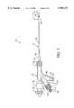
- FIG. 1is a side view of the present invention, a flexible tip rheolytic thrombectomy catheter useful for the removal of thrombus;
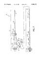
- FIG. 2is a semi-exploded side view of the flexible tip rheolytic thrombectomy catheter depicting the two major assemblies thereof, viz., an outer assembly and an inner assembly;
- FIG. 3is a cross sectional side view of a manifold and adjacent components constituting parts of the outer assembly
- FIG. 4is an isometric exploded view of the flexible tip assembly
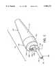
- FIG. 5is an isometric view of the assembled flexible tip assembly
- FIG. 6is a cross section view along line 6--6 of FIG. 1 illustrating the relationship of an outer body at the dual lumen tube distal end to the flexible tip assembly;
- FIG. 7is a partial cross section view of the junction of the hard plastic shell and the tapered and flexible tip
- FIG. 8is a cross section view of the dual lumen tube at the distal end along line 8--8 of FIG. 6;
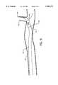
- FIG. 9is a view in cross section depicting the flexible tip assembly entering a branch artery or vessel, a tortuous path.
- FIG. 10is a view in cross section and partial cutaway depicting the operation of the distal end of the flexible tip rheolytic thrombectomy catheter at the site of a thrombotic deposit and lesion.
- FIG. 1illustrates a side view of a flexible tip rheolytic thrombectomy catheter 10 useful for the removal of thrombus
- FIG. 2illustrates a semi-exploded side view of the flexible tip rheolytic thrombectomy catheter 10.
- the flexible tip rheolytic thrombectomy catheter 10includes two major assemblies: namely, an outer assembly 12 and an inner assembly 14.
- the outer assembly 12 and the inner assembly 14are illustrated as separated, for the purpose of clarity, but in actual practice the majority of inner assembly 14 resides within the outer assembly and remains stationary with respect to the outer assembly 12.
- the inner assembly 14is constructed to fixedly align and to be held by a small lumen 47 of the dual lumen tube 38 (FIG.
- Externally visible components, or portions of components, of the outer assembly 12 of the rheolytic thrombectomy catheter 10, as illustrated in FIGS. 1 and 2,include a manifold 16, a hemostasis nut 18 secured in the proximal end 20 of the manifold 16, a Luer connection 22 located at the proximal end 23 of an angled manifold branch 24 extending from the manifold 16, a Luer connection 26 located at the proximal end 28 of an angled manifold branch 30 extending from the manifold 16, Luer fitting 32 secured to the distal end 34 of the manifold 16, a strain relief 36 secured to the distal end 34 of the manifold 16 by the Luer fitting 32, a first or dual lumen tube 38 of polyether block amide, polymer or other suitable materials, having a distal end 40 secured to the manifold 16 by the strain relief 36 and Luer fitting 32, and a flexible tip
- the externally visible components of the inner assembly 14, illustrated in FIG. 2,include a high pressure second or hypo-tube 44, a filter housing/high pressure connection assembly 46 concentrically aligned to and secured over and about the hypo-tube proximal end 48, and the flexible tip assembly 42 at the hypo-tube distal end 50.
- the high pressure hypo-tube 44is drawn and is tapered in incremental steps to provide degrees of flexibility along its length.
- the hypo-tube 44can include a hypo-tube portion 44a at the hypo-tube proximal end 48 having an outer diameter range of 0.015 to 0.025 inches, and can include a plurality of incrementally stepped down hypo-tube portions 44b-44n each of lesser outer diameter, where the last hypo-tube portion 44n is stepped down to an outer diameter range of 0.015 to 0.008 inches or less at the hypo-tube distal end 50.
- the hypo-tube 44becomes increasingly more flexible from the hypo-tube proximal end 48 towards the hypo-tube distal end 50 due to the incremental diameter decrease along its length. Increasing flexibility along the length of the hypo-tube 44 allows for easier flexed penetration into tortuous vascular paths.
- hypo-tube 44is stepped down in increments, the hypo-tube 44 can also be fashioned of a constantly decreasing outer diameter to provide increasing flexibility along its length and shall not be construed to be limiting to the scope of the invention.
- the tapered and flexible tipis characterized by a length to maximum diameter ratio of 1 to 10.
- FIG. 3illustrates a cross sectional side view of the manifold 16 and adjacent components, where all numerals correspond to those elements previously or otherwise described.
- the manifold 16includes a tapered centrally located main passage 52 aligned along the longitudinal axis of the manifold 16, a branch passage 54 extending along the axis of the branch 24 which intersects and is connected to the centrally located main passage 52, and another branch passage 55 extending along the axis of the branch 30 and intersecting the passage 54 of branch 24.
- the manifold proximal end 20houses a multi-radius cavity 56 for accommodation of the hemostasis nut 18 and an O-ring 58 which is compressed by action of the hemostasis nut 18 to act as a seal with or without a guidewire in place.
- a passage 60aligns centrally to the longitudinal axis of the hemostasis nut 18 and connects to the centrally located main passage 52, which is tapered so as to aid the front loading of a guidewire with the use of a guide
- the filter housing/high pressure connection assembly 46which is secured to the Luer connection 22 by a Luer fitting 61, includes a cylindrical-like body 62 having a threaded external surface 64, a tubular cavity 66, fine and coarse filters 68 and 70 residing in the tubular cavity 66, a central passage 72 extending through the body 62 and connecting with the tubular cavity 66, and an anchoring plug 74 within the tubular cavity 66 into which the hypo-tube 44 proximal end 48 suitably secures.
- the central passage 72communicates through the fine and course filters 68 and 70 with the centrally located lumen 76 (FIG. 4) of the hypo-tube 44.
- the strain relief 36is comprised of a tube 78 having a central bore 80 which accommodates the dual lumen tube 38, an external annular flange 82, and a tapered proximal tube mouth end 84. It is to be noted that the outer diameter of the tube 78 is constant from the annular flange 82 to the distal tube end 85, and that the outer diameter of the tube 78 steadily decreases from the annular flange 82 to the tapered proximal tube mouth end 84 to provide a tapered tube surface 86 which conforms, for purpose of a proper fit, to the tapered surface 87 of the tapered centrally located main passage 52.
- the tapered proximal tube mouth end 84 of the tube 78allows for easily accomplished alignment of guidewires or other assemblies with a large lumen 90 located in and extending along the interior of dual lumen tube 38.
- the Luer fitting 32threadingly engages a Luer connection 88 and bears against the annular flange 82 of the strain relief 36 to force the tapered tube surface 86 of the strain relief 36 against the tapered surface 87 of the tapered centrally located main passage 52 to effect a suitable seal.
- a small lumen 47(FIGS. 6 and 8) aligns in and extends along the interior of the dual lumen tube 38 parallel to the large lumen 90 and extends distally to the distal end 40 of the tubular dual lumen tube 38.
- the small lumen 47accommodates the hypo-tube 44 which connects at one end to the filter housing/high pressure connection assembly 46 and at the other to the flexible tip assembly 42, as shown in FIG. 6.
- FIG. 4illustrates an isometric exploded view of the flexible tip assembly 42, where all numerals correspond to those elements previously or otherwise described.
- the flexible tip assembly 42includes a tapered and flexible tip 94 of soft plastic polymer made of polyether block amides, or other such suitable material, and also includes a one-piece hard plastic polycarbonate shell 96 having a support extension 98 made of polycarbonate extending therefrom.
- a toroidal loop 100is located at the hypo-tube distal end 50 and is housed in and fixed within the hard plastic shell 96.
- the toroidal loop 100includes a plurality of jets 99a-99n on the rearward or proximally facing portion thereof each directed and/or aimed proximally at a slight inwardly projecting angle, as depicted in FIG. 7.
- the jets 99a-99nare located on the proximal region of the toroidal loop 100 and distributed as required along the locus of a circle having a common center with the toroidal loop 100.
- the hard plastic shell 96 and support extension 98are a one-piece structure including a cylindrical portion 102 aligned parallel to the longitudinal axis of the hypo-tube 44 and having an annular curved portion 104 extending rearwardly and inwardly from the cylindrical portion 102 to terminate substantially in a circular orifice 106.
- a cylindrical-like cavity 108 interior to the hard plastic shell 96accommodates the toroidal loop 100, as later described in detail in connection with FIG. 6.
- the support extension 98includes an interior curved surface 110 which accommodates and captures the hypo-tube distal end 50.
- the one-piece tapered and flexible tip 94includes a tapered surface 112 and an adjoining tubular member 114.
- a passage 116aligns along the axis of the tapered and flexible tip 94 and is utilized to accommodate a guidewire.
- the diameter of the tubular member 114is appropriately sized to align to and fit and be secured, such as with cyanoacrylate adhesive, within the cavity 108 of the hard plastic shell 96.
- the respective centers of the hard plastic shell 96, the toroidal loop 100 and the passage 116 of the tapered and flexible tip 94align about a mutual central longitudinal axis to provide a suitable guidewire path through the flexible tip assembly 42.
- FIG. 5illustrates an isometric view of the assembled flexible tip assembly 42, where all numerals correspond to those elements previously or otherwise described.
- FIG. 6illustrates a cross-section view along line 6--6 of FIG. 1 illustrating the relationship of an inner body 118 at the dual lumen tube distal end 40 to the flexible tip assembly 42, or stiff gap region, where all numerals correspond to those elements previously or otherwise described.
- the tapering of the tapered and flexible tip 94creates a stiffness transitional zone whereby the distal tip is more flexible than those tip regions positioned proximally. Increased flexibility as well as a smaller profile or cross-section at the most distal tip region allows for better tracking about a tortuous turn.
- Incorporation of the hard plastic shell 96allows a strong transitional bond and relationship to be maintained between the toroidal loop 100 and the tapered and flexible tip 94 while maintaining alignment integrity along the stiff gap region without undue stress placed across the gap 119 defined as the parallel and constant spacing between the distal annular region of the cylindrical inner body 118 and proximal annular region of the toroidal loop 100 residing in the hard plastic shell 96. Maintaining a constant and parallel spacing along and across the gap 119 is of great importance in maintaining proper flow of saline jet flow within the confines of the gap 119 and within the confines of the inner body 118.
- the cylindrical inner body 118aligns to and snappingly engages the dual lumen tube distal end 40 and is further secured thereto by aid of a radio-opaque outer body 120.
- the inner body 118includes a substantially annular tube 122 having an annular ring 124 thereabout which engages an annular groove 126 located on the interior of the distal end 40 of the dual lumen tube 38, an interior ramped annular inlet 128 aligned to and adjacent to a lumen 130, and an outer annular surface 132 which accommodates the radio-opaque outer body 120.
- epoxy adhesive 134is applied to smoothen transition from the outer body 120 to the dual lumen tube 38 and to aid in fastening the radio-opaque outer body 120 to the dual lumen tube distal end 40.
- the hypo-tube 44aligns in and is secured, by the filter housing/high pressure connection assembly 46, in the small lumen 47 of the dual lumen tube 38, and extends, at its distal end 50, through and is offset from the center of and is tangentially adjacent to one side of the lumen 130; extends through and is offset from the center of and is adjacent to one side of the ramped annular inlet 128; extends through, is glued to, such as by cyanoacrylate adhesive, and is captured by the support extension 98; and then terminates in the toroidal loop 100 previously described.
- the toroidal loop 100resides within the cavity 108 and is located and fastened by cyanoacrylate adhesive against the inner surface of the annular curved portion 104 of the hard plastic shell 96.
- the cavity 108could include additional capture geometry to allow snap-engagement of the toroidal loop 100, with or without adhesive, in the position shown. Care is exercised in the construction process, as later described, to preclude the deposition of adhesive material on the proximally facing jets 99a-99n located proximally on the toroidal loop 100.
- the proximally facing jets 99a-99nalign to direct saline jet flow proximally at a slight and inwardly projecting angle, as shown in FIG. 7.
- the saline jet flowbreaks up thrombotic material which is subsequently entrained and directed by the saline jet flow through the ramped annular inlet 128 and lumen 130 of the inner body 118 and thence into the large lumen 90, which functions as an evacuation lumen, of the dual lumen tube 38 for particulate and fluid evacuation.
- FIG. 7illustrates a partial cross-section view of the junction of the hard plastic shell 96 and the tapered and flexible tip 94, where all numerals correspond to those elements previously or otherwise described.
- Jets 99a-99nare fashioned in the proximal side of the toroidal loop 100 and are aligned at a slight and suitable angle to the longitudinal axis 135.
- Saline jet flow 136is directed at a slight inwardly projecting angle in a proximal direction from the jets 99a-99n through the orifice 106 formed between the annular curved portion 104 to break up and carry away thrombotic material, as previously described.
- FIG. 8illustrates a cross-section view of the dual lumen tube 38 at the distal end 40 along line 8--8 of FIG. 6, where all numerals correspond to those elements previously or otherwise described.
- the dual lumen tube 38is molded, extruded or otherwise formed to include an arcuate web 92 extending across the inner circumference of the dual lumen tube 38 to form the small lumen 47.
- the remaining area between the arcuate web 92 and the inner circumference of the dual lumen tube 38forms the large lumen 90 which can accommodate a guidewire or which can be utilized for evacuation of saline and/or thrombotic or other particulate.
- the hypo-tube 44within the small lumen 47.
- FIGS. 9 and 10best illustrate, in cross section and/or cutaway view, the mode of operation of the flexible tip rheolytic thrombectomy catheter 10 with particular attention to the dual lumen tube distal end 40 and flexible tip assembly 42 positioned in a blood vessel 138, artery or the like, enroute to (FIG. 9), or at the site of (FIG. 10) a thrombotic deposit and lesion 140 (FIG. 10).
- FIG. 9shows the flexible tip assembly 42 entering a branch artery or vessel 142, a tortuous path
- FIG. 10shows the operation of the distal end 40 of the dual lumen tube 38 of the flexible tip rheolytic thrombectomy catheter 10 at the site of a thrombotic deposit and lesion 140.
- a guidewire 144is first advanced percutaneously through the tortuous vasculature, such as through the blood vessel 138 and then into the branch artery or vessel 142, to the site of the thrombotic deposit and lesion such as or similar to the thrombotic deposit and lesion 140.
- the guidewiretypically has a diameter of 0.014 to 0.018 inch.
- the main passage 52 of the manifold 16 and the exhaust lumen 90 of the dual lumen tube 38serve as an evacuation tube.
- the rheolytic thrombectomy catheter 10can then be activated by providing high pressure liquid, preferably saline, to the proximal end of the dual lumen tube 38 via the manifold 16.
- High pressure saline, or other liquid, from the manifold 16is provided and flows through the lumen 76 of the hypo-tube 44 to exit jets 99a-99n of the toroidal loop 100.
- the high pressure saline jet flow 136exits the jets 99a-99n as retrograde jets of high velocity saline each being directed at a slight angle through the gap 119 and toward the ramped annular inlet 128 and lumen 130 of the inner body 118 and into the large lumen 90 of the dual lumen tube 38 for subsequent evacuation.
- Saline jet flow 136 from the high velocity saline jets 99a-99ndislodges tissue from the thrombotic deposit and lesion 140 and entrains it into the saline jet flow 136 where it is broken up into smaller fragments. Impingement of the saline jet flow 136 onto the dual lumen tube distal end 40 creates a stagnation pressure within the large lumen 90 that drives the debris particles of tissue from the thrombotic deposit and lesion 140 toward the proximal end of the dual lumen tube 38.
- a positive displacement piston pump(not illustrated) can be used to provide liquid, preferably saline, under pressure to the hypo-tube proximal end 48 via the filter housing/high pressure connection assembly 46 at the manifold branch 24.
- a pressure ranging from 500-15,000 psiwill provide the energy to create a useful high velocity jet as the saline exits the jets 99a-99n located at the proximal side of the toroidal loop 100.
- the flow rate of salinecan be controlled by adjusting the pumping rate of the positive displacement piston pump.
- the proximal end of the dual lumen tube 38interfaces with a metering device, such as a roller pump, through the Luer connection 26 at the manifold branch 30 prior to discharge of the evacuated thrombotic debris into a collection bag for disposal.
- the rate of evacuationcan be controlled by adjusting the rate of a roller pump (not illustrated) connected to the manifold branch 30.
- the rate of saline inflowcan be balanced with the rate of removal of thrombotic debris by simultaneous adjustment of the piston pump and the roller pump.
- the rate of saline inflowcan be less than, equal to, or greater than the rate of removal of thrombotic debris.
- the rate of thrombus removalcan be set to slightly exceed the rate of saline inflow to reduce the likelihood for distal embolization of thrombotic tissue.
- the flexible tip rheolytic thrombectomy catheter 10contains a high pressure hypo-tube 44 which is drawn down proximally to distally in successively smaller diameters which results in increased flexibility over a limited length.
- the hypo-tube 44is then closed on the distal end with a plasma weld technique.
- This distal end 40is then fashioned into a 90-degree bend of an appropriate length and then looped into a toroidal loop 100 of chosen dimensions.
- hypo-tube 44is threaded proximal end first through orifice 106 of the hard plastic shell 96.
- the shell 96is snappingly engaged with the toroidal loop 100 and the hypo-tube distal end 50 engages the support extension 98.
- the shelled toroidal assemblyis then appropriately inserted into a specialized tool such that all of the jets 99a-99n are masked such that they will not become occluded when cyanoacrylate adhesive is deposited onto the interface of the toroidal loop 100 and cavity 108 of the hard plastic shell 96 which is done to produce an appropriate bond intensity between the toroidal loop 100 and the hard plastic shell 96 that is required by the design.
- This assemblyis further constructed by adding a concentrically affixed inner body 118 by way of alignment slot 155, in relation to the toroidal loop 100 and hard plastic shell 96, to the hypo-tube 44 such as to produce an optimally scaled gap 119.
- a radio-opaque outer body 120is then guided into position over the outer diameter of the distal end 40 of the dual lumen tube 38 such that the dual lumen tube 38 is compressively held.
- this jointis further improved by the use of epoxy adhesive 134 or cyanoacrylate or another suitable material.
- the transition between the outer body 120 and dual lumen tube 38is minimized by the use of epoxy adhesive 134 or another suitable adhesive or with a sufficiently tapered outer body 120.
- the tapered and flexible tip 94which is also made of a polyether block amide polymer or another suitable flexible and possibly soft material can be attached at any point in the process but is optimally attached at a point in the process to minimize the agglomeration of foreign material to its tapered surface 112.
- Cyanoacrylate or another appropriate adhesiveis applied controllably and effectively to the flexible tip tubular member 114.
- the tapered and flexible tip 94is then mechanically inserted into an appropriately mated cavity 108 of the hard plastic shell 96 which is done to produce an appropriate bond intensity between the hard plastic shell 96 and the tapered and flexible tip 94 that is required by the design.
- the previously described assemblyis then either proximally inserted into the manifold 16 into passage 52, through passage 54 or distally through passage 54 and then passage 52.
- the suitably preassembled filter housing/high pressure connection 46is affixed to the hypo-tube proximal end 48 by way of a compressive anchoring plug 74.
- the strain relief 36is placed over the proximal end of the dual lumen tube 38.
- the tapered surface 86 of the strain relief 36which is composed of a proper flexible material is then compressively captured and seated so as to produce an appropriate seal against tapered surface 87 and dual lumen tube 38 of the manifold 16 by way of Luer fitting 32 which mechanically advances the strain relief 36 by way of physical interference of the annular flange 82 and the torquedly advanced Luer fitting 32.
- the filter housing/high pressure connection 46is similarly seated and sealed against tapered surface 155 of passage 54 by way of Luer fitting 61. These seals are designed such that pressures of 0 to 300 psi can be easily contained without the aid of further intervention by way of adhesive or another similar substance.
- the O-ring 58 and hemostasis nut 18can be positioned into manifold 16 at any point in the assembly operation.
- the flexible tip rheolytic thrombectomy catheter 12which has been assembled to the previously described degree then is allowed to continue on into normal catheter testing, packaging, etc. procedures.
Landscapes
- Health & Medical Sciences (AREA)
- Surgery (AREA)
- Life Sciences & Earth Sciences (AREA)
- Biomedical Technology (AREA)
- Nuclear Medicine, Radiotherapy & Molecular Imaging (AREA)
- Engineering & Computer Science (AREA)
- Vascular Medicine (AREA)
- Heart & Thoracic Surgery (AREA)
- Medical Informatics (AREA)
- Molecular Biology (AREA)
- Animal Behavior & Ethology (AREA)
- General Health & Medical Sciences (AREA)
- Public Health (AREA)
- Veterinary Medicine (AREA)
- Surgical Instruments (AREA)
Abstract
Description
______________________________________ 10 flexible tip rheolytic 44a-n hypo-tube portion thrombectomy catheter 45 small lumen 12 outer assembly filter housing/high 14 inner assembly pressure connection 16 manifold assembly 18 hemostasis nut small lumen hypo-tube proximal end 20 manifold proximal end 50 hypo-tube distal end 22 Luer connection passage (main) 23 proximal end passage (branch 24) 24 manifold branch passage (branch 30) 26 Luer connection 28 proximal end multi-radius cavity 30 manifold branch O-ring 32 Luer fitting passage 34 distal end Luer fitting 36 strain relief body 38 dual lumen tube threaded surface 40 distal end tubular cavity 42 flexible tip assembly 68 fine filter 44 high pressure second 70 coarse filter or hypo-tube 72 passage 74 anchoring plug 76 lumen (hypo-tube) tubular member 78 tube passage 80 bore inner body 82 annular flange gap 84 tapered proximal tube 120 radio-opaque outer body mouth end annular tube 85 distal tube end annular ring 86 tapered tube surface 126 annular groove 87 tapered surface ramped annular inlet 88 Luer connection lumen 90 exhaust lumen (large) 132 annular surface 92 arcuate web epoxy adhesive 94 tapered and flexible 135 longitudinal axis tip saline jet flow 96 hard plastic shell blood vessel 98 support extension thrombotic deposit and 99a-n jets lesion 100 toroidal loop branch artery or vessel 102 cylindrical portion 144 guidewire 104 annular curved portion 155 tapered surface 106 orifice 108 cavity 110 curved surface 112 tapered surface ______________________________________
Claims (19)
Priority Applications (1)
| Application Number | Priority Date | Filing Date | Title |
|---|---|---|---|
| US09/188,631US5989271A (en) | 1998-11-09 | 1998-11-09 | Flexible tip rheolytic thrombectomy catheter and method of constructing same |
Applications Claiming Priority (1)
| Application Number | Priority Date | Filing Date | Title |
|---|---|---|---|
| US09/188,631US5989271A (en) | 1998-11-09 | 1998-11-09 | Flexible tip rheolytic thrombectomy catheter and method of constructing same |
Publications (1)
| Publication Number | Publication Date |
|---|---|
| US5989271Atrue US5989271A (en) | 1999-11-23 |
Family
ID=22693943
Family Applications (1)
| Application Number | Title | Priority Date | Filing Date |
|---|---|---|---|
| US09/188,631Expired - Fee RelatedUS5989271A (en) | 1998-11-09 | 1998-11-09 | Flexible tip rheolytic thrombectomy catheter and method of constructing same |
Country Status (1)
| Country | Link |
|---|---|
| US (1) | US5989271A (en) |
Cited By (115)
| Publication number | Priority date | Publication date | Assignee | Title |
|---|---|---|---|---|
| US6241703B1 (en)* | 1996-08-19 | 2001-06-05 | Angiosonics Inc. | Ultrasound transmission apparatus having a tip |
| US6371969B1 (en) | 1997-05-08 | 2002-04-16 | Scimed Life Systems, Inc. | Distal protection device and method |
| US6371971B1 (en) | 1999-11-15 | 2002-04-16 | Scimed Life Systems, Inc. | Guidewire filter and methods of use |
| US6371970B1 (en) | 1999-07-30 | 2002-04-16 | Incept Llc | Vascular filter having articulation region and methods of use in the ascending aorta |
| US6530939B1 (en) | 1999-07-30 | 2003-03-11 | Incept, Llc | Vascular device having articulation region and methods of use |
| US6537295B2 (en) | 2001-03-06 | 2003-03-25 | Scimed Life Systems, Inc. | Wire and lock mechanism |
| US6544279B1 (en) | 2000-08-09 | 2003-04-08 | Incept, Llc | Vascular device for emboli, thrombus and foreign body removal and methods of use |
| US6544280B1 (en) | 1999-02-24 | 2003-04-08 | Scimed Life Systems, Inc. | Intravascular filter and method |
| US6572578B1 (en) | 2000-08-25 | 2003-06-03 | Patrick A. Blanchard | Fluid-jet catheter and its application to flexible endoscopy |
| US6589263B1 (en) | 1999-07-30 | 2003-07-08 | Incept Llc | Vascular device having one or more articulation regions and methods of use |
| US20030130672A1 (en)* | 2002-01-10 | 2003-07-10 | Scimed Life Systems, Inc. | Aspirating balloon catheter for treating vulnerable plaque |
| US6616681B2 (en) | 2000-10-05 | 2003-09-09 | Scimed Life Systems, Inc. | Filter delivery and retrieval device |
| US6616679B1 (en) | 1999-07-30 | 2003-09-09 | Incept, Llc | Rapid exchange vascular device for emboli and thrombus removal and methods of use |
| US6620182B1 (en) | 1999-07-30 | 2003-09-16 | Incept Llc | Vascular filter having articulation region and methods of use in the ascending aorta |
| US6620148B1 (en) | 1999-08-04 | 2003-09-16 | Scimed Life Systems, Inc. | Filter flush system and methods of use |
| US6652505B1 (en) | 1999-08-03 | 2003-11-25 | Scimed Life Systems Inc. | Guided filter with support wire and methods of use |
| US6663651B2 (en) | 2001-01-16 | 2003-12-16 | Incept Llc | Systems and methods for vascular filter retrieval |
| US6673090B2 (en) | 1999-08-04 | 2004-01-06 | Scimed Life Systems, Inc. | Percutaneous catheter and guidewire for filtering during ablation of myocardial or vascular tissue |
| US6676682B1 (en) | 1997-05-08 | 2004-01-13 | Scimed Life Systems, Inc. | Percutaneous catheter and guidewire having filter and medical device deployment capabilities |
| US6676627B1 (en)* | 1990-08-06 | 2004-01-13 | Possis Medical, Inc. | Crossflow thrombectomy catheter and system |
| US6689151B2 (en) | 2001-01-25 | 2004-02-10 | Scimed Life Systems, Inc. | Variable wall thickness for delivery sheath housing |
| US6755847B2 (en) | 2001-10-05 | 2004-06-29 | Scimed Life Systems, Inc. | Emboli capturing device and method of manufacture therefor |
| US6951570B2 (en) | 2001-07-02 | 2005-10-04 | Rubicon Medical, Inc. | Methods, systems, and devices for deploying a filter from a filter device |
| US6962598B2 (en) | 2001-07-02 | 2005-11-08 | Rubicon Medical, Inc. | Methods, systems, and devices for providing embolic protection |
| US6997939B2 (en) | 2001-07-02 | 2006-02-14 | Rubicon Medical, Inc. | Methods, systems, and devices for deploying an embolic protection filter |
| US7052500B2 (en) | 2001-10-19 | 2006-05-30 | Scimed Life Systems, Inc. | Embolus extractor |
| US20060129091A1 (en)* | 2004-12-10 | 2006-06-15 | Possis Medical, Inc. | Enhanced cross stream mechanical thrombectomy catheter with backloading manifold |
| US7094249B1 (en) | 1997-03-06 | 2006-08-22 | Boston Scientific Scimed, Inc. | Distal protection device and method |
| US20060282116A1 (en)* | 2004-01-20 | 2006-12-14 | Scimed Life Systems, Inc. | Sheath for use with an embolic protection filtering protection |
| US7204464B2 (en) | 2005-01-21 | 2007-04-17 | Boston Scientific Scimed, Inc. | Medical wire holder |
| US7220269B1 (en)* | 2003-11-06 | 2007-05-22 | Possis Medical, Inc. | Thrombectomy catheter system with occluder and method of using same |
| US7320697B2 (en) | 1999-07-30 | 2008-01-22 | Boston Scientific Scimed, Inc. | One piece loop and coil |
| WO2008051898A3 (en)* | 2006-10-22 | 2008-07-03 | Via Biomedical Inc | Devices and methods for unwrapping or preventing the wrapping of elongated medical devices |
| US20080188831A1 (en)* | 2007-02-06 | 2008-08-07 | Possis Medical, Inc. | Miniature flexible thrombectomy catheter |
| US20080275393A1 (en)* | 2004-08-24 | 2008-11-06 | Bonnette Michael J | Isolation thrombectomy catheter system |
| US20080289181A1 (en)* | 2007-02-06 | 2008-11-27 | Possis Medical, Inc. | Method of manufacturing a miniature flexible thrombectomy catheter |
| US20080300574A1 (en)* | 2005-07-06 | 2008-12-04 | Amir Belson | Intravenous Catheter Insertion Device and Method of Use |
| US20080312672A1 (en)* | 2007-06-12 | 2008-12-18 | Possis Medical, Inc. | Forwardly directed fluid jet crossing catheter |
| US20080312681A1 (en)* | 2006-10-16 | 2008-12-18 | Possis Medical, Inc. | Catheter for removal of an organized embolic thrombus |
| US7473265B2 (en) | 2004-03-15 | 2009-01-06 | Boston Scientific Scimed, Inc. | Filter media and methods of manufacture |
| US7478465B1 (en) | 2005-01-10 | 2009-01-20 | Boston Scientific Scimed, Inc. | Method of securing a restraining member on a medical device |
| US20090171267A1 (en)* | 2007-12-26 | 2009-07-02 | Medrad, Inc. | Rheolytic thrombectomy catheter with self-inflating proximal balloon with drug infusion capabilities |
| US7563272B2 (en) | 1999-07-16 | 2009-07-21 | Boston Scientific Scimed, Inc. | Emboli filtration system and methods of use |
| US7572244B2 (en) | 2004-08-02 | 2009-08-11 | Medrad, Inc. | Miniature cross stream thrombectomy catheter |
| US7594926B2 (en) | 2001-11-09 | 2009-09-29 | Boston Scientific Scimed, Inc. | Methods, systems and devices for delivering stents |
| US7621904B2 (en) | 2004-10-21 | 2009-11-24 | Boston Scientific Scimed, Inc. | Catheter with a pre-shaped distal tip |
| US7632242B2 (en) | 2004-12-09 | 2009-12-15 | Boston Scientific Scimed, Inc. | Catheter including a compliant balloon |
| US7651514B2 (en) | 2003-12-11 | 2010-01-26 | Boston Scientific Scimed, Inc. | Nose rider improvement for filter exchange and methods of use |
| US7695465B2 (en) | 2001-07-30 | 2010-04-13 | Boston Scientific Scimed, Inc. | Chronic total occlusion device with variable stiffness shaft |
| US7708770B2 (en) | 2001-11-09 | 2010-05-04 | Boston Scientific Scimed, Inc. | Stent delivery device with embolic protection |
| US7780611B2 (en) | 2003-05-01 | 2010-08-24 | Boston Scientific Scimed, Inc. | Medical instrument with controlled torque transmission |
| US7794472B2 (en) | 2004-08-11 | 2010-09-14 | Boston Scientific Scimed, Inc. | Single wire intravascular filter |
| US7875050B2 (en) | 1997-09-30 | 2011-01-25 | Target Therapeutics, Inc. | Mechanical clot treatment device |
| US7998163B2 (en) | 2002-10-03 | 2011-08-16 | Boston Scientific Scimed, Inc. | Expandable retrieval device |
| US8038696B2 (en) | 2004-12-06 | 2011-10-18 | Boston Scientific Scimed, Inc. | Sheath for use with an embolic protection filter |
| US8123777B2 (en) | 2001-07-24 | 2012-02-28 | Incept, Llc | Apparatus and methods for aspirating emboli |
| US8162878B2 (en) | 2005-12-05 | 2012-04-24 | Medrad, Inc. | Exhaust-pressure-operated balloon catheter system |
| US8236024B2 (en) | 2001-02-20 | 2012-08-07 | Boston Scientific Scimed, Inc. | Low profile emboli capture device |
| US8241315B2 (en) | 2004-06-24 | 2012-08-14 | Boston Scientific Scimed, Inc. | Apparatus and method for treating occluded vasculature |
| US8303538B2 (en) | 2007-12-17 | 2012-11-06 | Medrad, Inc. | Rheolytic thrombectomy catheter with self-inflating distal balloon |
| US8444669B2 (en) | 2008-12-15 | 2013-05-21 | Boston Scientific Scimed, Inc. | Embolic filter delivery system and method |
| US8468678B2 (en) | 2002-10-02 | 2013-06-25 | Boston Scientific Scimed, Inc. | Expandable retrieval device |
| US8480629B2 (en) | 2005-01-28 | 2013-07-09 | Boston Scientific Scimed, Inc. | Universal utility board for use with medical devices and methods of use |
| US8535344B2 (en) | 2003-09-12 | 2013-09-17 | Rubicon Medical, Inc. | Methods, systems, and devices for providing embolic protection and removing embolic material |
| US20130267891A1 (en)* | 2012-01-26 | 2013-10-10 | Covidien Lp | Thrombectomy catheter systems |
| US8562555B2 (en) | 2001-07-17 | 2013-10-22 | John M. MacMahon | Fluid exchange system for controlled and localized irrigation and aspiration |
| US8647294B2 (en) | 2008-03-20 | 2014-02-11 | Medrad, Inc. | Direct stream hydrodynamic catheter system |
| US8795322B2 (en) | 2002-04-01 | 2014-08-05 | W. L. Gore & Associates, Inc. | Methods of manufacture and use of endoluminal devices |
| US8821478B2 (en) | 2011-03-04 | 2014-09-02 | Boston Scientific Scimed, Inc. | Catheter with variable stiffness |
| US20140316392A1 (en)* | 2013-03-15 | 2014-10-23 | The Regents Of The University Of California | Method, Apparatus, and a System for a Water Jet |
| US9023076B2 (en) | 2002-10-17 | 2015-05-05 | W. L. Gore & Associates, Inc. | Embolic filter frame having looped support strut elements |
| US9204887B2 (en) | 2012-08-14 | 2015-12-08 | W. L. Gore & Associates, Inc. | Devices and systems for thrombus treatment |
| US9254144B2 (en) | 2007-03-30 | 2016-02-09 | Covidien Lp | Methods and apparatus for thrombectomy system |
| US9522254B2 (en) | 2013-01-30 | 2016-12-20 | Vascular Pathways, Inc. | Systems and methods for venipuncture and catheter placement |
| US9586023B2 (en) | 1998-02-06 | 2017-03-07 | Boston Scientific Limited | Direct stream hydrodynamic catheter system |
| US9616201B2 (en) | 2011-01-31 | 2017-04-11 | Vascular Pathways, Inc. | Intravenous catheter and insertion device with reduced blood spatter |
| US9675784B2 (en) | 2007-04-18 | 2017-06-13 | Vascular Pathways, Inc. | Intravenous catheter insertion and blood sample devices and method of use |
| US20170172590A1 (en)* | 2014-03-21 | 2017-06-22 | Terumo Kabushiki Kaisha | Calculus retrieving/removing device and method |
| US9827084B2 (en) | 2007-10-26 | 2017-11-28 | Embolitech, Llc | Intravascular guidewire filter system for pulmonary embolism protection and embolism removal or maceration |
| US9861792B2 (en) | 2011-02-25 | 2018-01-09 | C. R. Bard, Inc. | Medical component insertion device including a retractable needle |
| US9872971B2 (en) | 2010-05-14 | 2018-01-23 | C. R. Bard, Inc. | Guidewire extension system for a catheter placement device |
| US9950139B2 (en) | 2010-05-14 | 2018-04-24 | C. R. Bard, Inc. | Catheter placement device including guidewire and catheter control elements |
| US10232146B2 (en) | 2014-09-05 | 2019-03-19 | C. R. Bard, Inc. | Catheter insertion device including retractable needle |
| US10335262B2 (en)* | 2007-02-02 | 2019-07-02 | Covidien Lp | Embolic protection devices having short landing zones |
| US20190209745A1 (en)* | 2018-01-10 | 2019-07-11 | Boston Scientific Scimed, Inc. | Aspiration medical device |
| US10384039B2 (en) | 2010-05-14 | 2019-08-20 | C. R. Bard, Inc. | Catheter insertion device including top-mounted advancement components |
| US10493262B2 (en) | 2016-09-12 | 2019-12-03 | C. R. Bard, Inc. | Blood control for a catheter insertion device |
| EP3689274A1 (en)* | 2007-02-05 | 2020-08-05 | Boston Scientific Limited | Thrombectomy system |
| USD903100S1 (en) | 2015-05-01 | 2020-11-24 | C. R. Bard, Inc. | Catheter placement device |
| USD903101S1 (en) | 2011-05-13 | 2020-11-24 | C. R. Bard, Inc. | Catheter |
| US11000678B2 (en) | 2010-05-14 | 2021-05-11 | C. R. Bard, Inc. | Catheter placement device and method |
| WO2021097215A1 (en)* | 2019-11-14 | 2021-05-20 | Ischemicure Ltd | Devices, systems and methods to remove blood clots |
| USD921884S1 (en) | 2018-07-27 | 2021-06-08 | Bard Access Systems, Inc. | Catheter insertion device |
| US11040176B2 (en) | 2015-05-15 | 2021-06-22 | C. R. Bard, Inc. | Catheter placement device including an extensible needle safety component |
| US11065017B2 (en) | 2018-01-25 | 2021-07-20 | Ischemicure Ltd. | Devices, systems and methods to remove blood clots |
| US11103263B2 (en) | 2015-07-24 | 2021-08-31 | Ichor Vascular Inc. | Embolectomy system and methods of making and using same |
| US11129702B2 (en) | 2018-05-09 | 2021-09-28 | Boston Scientific Scimed, Inc. | Pedal access embolic filtering sheath |
| US11389626B2 (en) | 2018-03-07 | 2022-07-19 | Bard Access Systems, Inc. | Guidewire advancement and blood flashback systems for a medical device insertion system |
| US11400260B2 (en) | 2017-03-01 | 2022-08-02 | C. R. Bard, Inc. | Catheter insertion device |
| US11490909B2 (en) | 2014-05-19 | 2022-11-08 | Walk Vascular, Llc | Systems and methods for removal of blood and thrombotic material |
| US11497521B2 (en) | 2008-10-13 | 2022-11-15 | Walk Vascular, Llc | Assisted aspiration catheter system |
| US11510689B2 (en) | 2016-04-06 | 2022-11-29 | Walk Vascular, Llc | Systems and methods for thrombolysis and delivery of an agent |
| US11559665B2 (en) | 2019-08-19 | 2023-01-24 | Becton, Dickinson And Company | Midline catheter placement device |
| WO2023002926A1 (en)* | 2021-07-20 | 2023-01-26 | 大塚テクノ株式会社 | Urinary catheter and jointing part for urinary catheter |
| US11602617B2 (en) | 2019-04-18 | 2023-03-14 | Michael Bonnette | Pumpless thrombectomy system |
| JP2023516439A (en)* | 2020-03-04 | 2023-04-19 | シファメド・ホールディングス・エルエルシー | Thrombectomy system and related methods |
| US11672561B2 (en) | 2015-09-03 | 2023-06-13 | Walk Vascular, Llc | Systems and methods for manipulating medical devices |
| US11678905B2 (en) | 2018-07-19 | 2023-06-20 | Walk Vascular, Llc | Systems and methods for removal of blood and thrombotic material |
| US11826064B2 (en) | 2018-06-15 | 2023-11-28 | Incuvate, Llc | Systems and methods for aspiration and monitoring |
| US11925779B2 (en) | 2010-05-14 | 2024-03-12 | C. R. Bard, Inc. | Catheter insertion device including top-mounted advancement components |
| US11969176B2 (en) | 2021-05-04 | 2024-04-30 | Boston Scientific Scimed, Inc. | Aspiration medical device |
| US12171444B2 (en) | 2021-02-15 | 2024-12-24 | Walk Vascular, Llc | Systems and methods for removal of blood and thrombotic material |
| US12274458B2 (en) | 2021-02-15 | 2025-04-15 | Walk Vascular, Llc | Systems and methods for removal of blood and thrombotic material |
| US12280222B2 (en) | 2023-08-28 | 2025-04-22 | Incuvate, Llc | Systems and methods for injection and aspiration |
| US12440652B2 (en) | 2019-09-20 | 2025-10-14 | Bard Peripheral Vascular, Inc. | Intravenous catheter-placement device and method thereof |
Citations (2)
| Publication number | Priority date | Publication date | Assignee | Title |
|---|---|---|---|---|
| US5320599A (en)* | 1990-02-14 | 1994-06-14 | Cordis Corporation | Drainage catheter |
| US5370609A (en)* | 1990-08-06 | 1994-12-06 | Possis Medical, Inc. | Thrombectomy device |
- 1998
- 1998-11-09USUS09/188,631patent/US5989271A/ennot_activeExpired - Fee Related
Patent Citations (2)
| Publication number | Priority date | Publication date | Assignee | Title |
|---|---|---|---|---|
| US5320599A (en)* | 1990-02-14 | 1994-06-14 | Cordis Corporation | Drainage catheter |
| US5370609A (en)* | 1990-08-06 | 1994-12-06 | Possis Medical, Inc. | Thrombectomy device |
Cited By (223)
| Publication number | Priority date | Publication date | Assignee | Title |
|---|---|---|---|---|
| US6676627B1 (en)* | 1990-08-06 | 2004-01-13 | Possis Medical, Inc. | Crossflow thrombectomy catheter and system |
| US6805684B2 (en)* | 1990-08-06 | 2004-10-19 | Possis Medical, Inc. | Thrombectomy catheter and system |
| US6719718B2 (en)* | 1990-08-06 | 2004-04-13 | Possis Medical, Inc. | Thrombectomy catheter and system |
| US6241703B1 (en)* | 1996-08-19 | 2001-06-05 | Angiosonics Inc. | Ultrasound transmission apparatus having a tip |
| US7094249B1 (en) | 1997-03-06 | 2006-08-22 | Boston Scientific Scimed, Inc. | Distal protection device and method |
| US6371969B1 (en) | 1997-05-08 | 2002-04-16 | Scimed Life Systems, Inc. | Distal protection device and method |
| US6964673B2 (en) | 1997-05-08 | 2005-11-15 | Scimed Life Systems, Inc. | Percutaneous catheter and guidewire having filter and medical device deployment capabilities |
| US7691123B2 (en) | 1997-05-08 | 2010-04-06 | Boston Scientific Scimed, Inc. | Percutaneous catheter and guidewire having filter and medical device deployment capabilities |
| US6676682B1 (en) | 1997-05-08 | 2004-01-13 | Scimed Life Systems, Inc. | Percutaneous catheter and guidewire having filter and medical device deployment capabilities |
| US8486104B2 (en) | 1997-09-30 | 2013-07-16 | Stryker Corporation | Mechanical clot treatment device with distal filter |
| US7875050B2 (en) | 1997-09-30 | 2011-01-25 | Target Therapeutics, Inc. | Mechanical clot treatment device |
| US10321932B2 (en) | 1998-02-06 | 2019-06-18 | Boston Scientific Limited | Direct stream hydrodynamic catheter system |
| US9586023B2 (en) | 1998-02-06 | 2017-03-07 | Boston Scientific Limited | Direct stream hydrodynamic catheter system |
| US7618433B2 (en) | 1999-02-24 | 2009-11-17 | Boston Scientific Scimed, Inc. | Intravascular filter and method |
| US8303618B2 (en) | 1999-02-24 | 2012-11-06 | Boston Scientific Scimed, Inc. | Intravascular filter and method |
| US9119706B2 (en) | 1999-02-24 | 2015-09-01 | Boston Scientific Scimed Inc. | Intravascular filter and method |
| US6544280B1 (en) | 1999-02-24 | 2003-04-08 | Scimed Life Systems, Inc. | Intravascular filter and method |
| US7563272B2 (en) | 1999-07-16 | 2009-07-21 | Boston Scientific Scimed, Inc. | Emboli filtration system and methods of use |
| US7699866B2 (en) | 1999-07-16 | 2010-04-20 | Boston Scientific Scimed, Inc. | Emboli filtration system and methods of use |
| US8617201B2 (en) | 1999-07-30 | 2013-12-31 | Incept Llc | Vascular device for emboli, thrombus and foreign body removal and methods of use |
| US6589263B1 (en) | 1999-07-30 | 2003-07-08 | Incept Llc | Vascular device having one or more articulation regions and methods of use |
| US6616679B1 (en) | 1999-07-30 | 2003-09-09 | Incept, Llc | Rapid exchange vascular device for emboli and thrombus removal and methods of use |
| US6620182B1 (en) | 1999-07-30 | 2003-09-16 | Incept Llc | Vascular filter having articulation region and methods of use in the ascending aorta |
| USRE43902E1 (en) | 1999-07-30 | 2013-01-01 | Incept, Llc | Vascular device for emboli, thrombus and foreign body removal and methods of use |
| US9283066B2 (en) | 1999-07-30 | 2016-03-15 | Incept Llc | Vascular device for emboli, thrombus and foreign body removal and methods of use |
| USRE43882E1 (en) | 1999-07-30 | 2012-12-25 | Incept, Llc | Vascular device for emboli, thrombus and foreign body removal and methods of use |
| US7410491B2 (en) | 1999-07-30 | 2008-08-12 | Incept Llc | Vascular device for emboli, thrombus and foreign body removal and methods of use |
| US6530939B1 (en) | 1999-07-30 | 2003-03-11 | Incept, Llc | Vascular device having articulation region and methods of use |
| US7320697B2 (en) | 1999-07-30 | 2008-01-22 | Boston Scientific Scimed, Inc. | One piece loop and coil |
| US6371970B1 (en) | 1999-07-30 | 2002-04-16 | Incept Llc | Vascular filter having articulation region and methods of use in the ascending aorta |
| US7235061B2 (en) | 1999-08-03 | 2007-06-26 | Boston Scientific Scimed, Inc. | Guided filter with support wire and methods of use |
| US6652505B1 (en) | 1999-08-03 | 2003-11-25 | Scimed Life Systems Inc. | Guided filter with support wire and methods of use |
| US7326226B2 (en) | 1999-08-04 | 2008-02-05 | Boston Scientific Scimed, Inc. | Percutaneous catheter and guidewire for filtering during ablation of myocardial or vascular tissue |
| US6673090B2 (en) | 1999-08-04 | 2004-01-06 | Scimed Life Systems, Inc. | Percutaneous catheter and guidewire for filtering during ablation of myocardial or vascular tissue |
| US6620148B1 (en) | 1999-08-04 | 2003-09-16 | Scimed Life Systems, Inc. | Filter flush system and methods of use |
| US8444665B2 (en) | 1999-08-04 | 2013-05-21 | Boston Scientific Scimed, Inc. | Filter flush system and methods of use |
| US6371971B1 (en) | 1999-11-15 | 2002-04-16 | Scimed Life Systems, Inc. | Guidewire filter and methods of use |
| US6544279B1 (en) | 2000-08-09 | 2003-04-08 | Incept, Llc | Vascular device for emboli, thrombus and foreign body removal and methods of use |
| US6572578B1 (en) | 2000-08-25 | 2003-06-03 | Patrick A. Blanchard | Fluid-jet catheter and its application to flexible endoscopy |
| US7229464B2 (en) | 2000-10-05 | 2007-06-12 | Scimed Life Systems, Inc. | Filter delivery and retrieval device |
| US6616681B2 (en) | 2000-10-05 | 2003-09-09 | Scimed Life Systems, Inc. | Filter delivery and retrieval device |
| US8460336B2 (en) | 2001-01-16 | 2013-06-11 | Incept Llc | Systems and methods for vascular filter retrieval |
| US6663651B2 (en) | 2001-01-16 | 2003-12-16 | Incept Llc | Systems and methods for vascular filter retrieval |
| US7097652B2 (en) | 2001-01-25 | 2006-08-29 | Scimed Life Systems, Inc. | Variable wall thickness for delivery sheath housing |
| US6689151B2 (en) | 2001-01-25 | 2004-02-10 | Scimed Life Systems, Inc. | Variable wall thickness for delivery sheath housing |
| US8236024B2 (en) | 2001-02-20 | 2012-08-07 | Boston Scientific Scimed, Inc. | Low profile emboli capture device |
| US6537295B2 (en) | 2001-03-06 | 2003-03-25 | Scimed Life Systems, Inc. | Wire and lock mechanism |
| US6991642B2 (en) | 2001-03-06 | 2006-01-31 | Scimed Life Systems, Inc. | Wire and lock mechanism |
| US8262690B2 (en) | 2001-03-06 | 2012-09-11 | Boston Scientific Scimed, Inc. | Wire and lock mechanism |
| US6962598B2 (en) | 2001-07-02 | 2005-11-08 | Rubicon Medical, Inc. | Methods, systems, and devices for providing embolic protection |
| US6951570B2 (en) | 2001-07-02 | 2005-10-04 | Rubicon Medical, Inc. | Methods, systems, and devices for deploying a filter from a filter device |
| US6997939B2 (en) | 2001-07-02 | 2006-02-14 | Rubicon Medical, Inc. | Methods, systems, and devices for deploying an embolic protection filter |
| US8562555B2 (en) | 2001-07-17 | 2013-10-22 | John M. MacMahon | Fluid exchange system for controlled and localized irrigation and aspiration |
| US8123777B2 (en) | 2001-07-24 | 2012-02-28 | Incept, Llc | Apparatus and methods for aspirating emboli |
| US7695465B2 (en) | 2001-07-30 | 2010-04-13 | Boston Scientific Scimed, Inc. | Chronic total occlusion device with variable stiffness shaft |
| US6755847B2 (en) | 2001-10-05 | 2004-06-29 | Scimed Life Systems, Inc. | Emboli capturing device and method of manufacture therefor |
| US7320698B2 (en) | 2001-10-05 | 2008-01-22 | Boston Scientific Scimed, Inc. | Emboli capturing device and method of manufacture therefor |
| US7052500B2 (en) | 2001-10-19 | 2006-05-30 | Scimed Life Systems, Inc. | Embolus extractor |
| US8579957B2 (en) | 2001-11-09 | 2013-11-12 | Boston Scientific Scimed, Inc. | Stent delivery device with embolic protection |
| US7708770B2 (en) | 2001-11-09 | 2010-05-04 | Boston Scientific Scimed, Inc. | Stent delivery device with embolic protection |
| US7594926B2 (en) | 2001-11-09 | 2009-09-29 | Boston Scientific Scimed, Inc. | Methods, systems and devices for delivering stents |
| US7189250B2 (en) | 2002-01-10 | 2007-03-13 | Scimed Life Systems, Inc. | Aspirating balloon catheter for treating vulnerable plaque |
| US20030130672A1 (en)* | 2002-01-10 | 2003-07-10 | Scimed Life Systems, Inc. | Aspirating balloon catheter for treating vulnerable plaque |
| US8795322B2 (en) | 2002-04-01 | 2014-08-05 | W. L. Gore & Associates, Inc. | Methods of manufacture and use of endoluminal devices |
| US8801750B2 (en) | 2002-04-01 | 2014-08-12 | W.L. Gore & Associates, Inc. | Methods of manufacture and use of endoluminal devices |
| US8468678B2 (en) | 2002-10-02 | 2013-06-25 | Boston Scientific Scimed, Inc. | Expandable retrieval device |
| US7998163B2 (en) | 2002-10-03 | 2011-08-16 | Boston Scientific Scimed, Inc. | Expandable retrieval device |
| US9023076B2 (en) | 2002-10-17 | 2015-05-05 | W. L. Gore & Associates, Inc. | Embolic filter frame having looped support strut elements |
| US9642691B2 (en) | 2002-10-17 | 2017-05-09 | W. L. Gore & Associates, Inc | Vessel occlusion device and method of using same |
| US9023077B2 (en) | 2002-10-17 | 2015-05-05 | W.L. Gore & Associates, Inc. | Embolic filter frame having looped support strut elements |
| US8845552B2 (en) | 2003-05-01 | 2014-09-30 | Boston Scientific Scimed, Inc. | Medical instrument with controlled torque transmission |
| US8292829B2 (en) | 2003-05-01 | 2012-10-23 | Boston Scientific Scimed, Inc. | Medical instrument with controlled torque transmission |
| US7780611B2 (en) | 2003-05-01 | 2010-08-24 | Boston Scientific Scimed, Inc. | Medical instrument with controlled torque transmission |
| US8998843B2 (en) | 2003-06-05 | 2015-04-07 | Boston Scientific Limited | Enhanced cross stream mechanical thrombectomy catheter |
| US9833257B2 (en) | 2003-06-05 | 2017-12-05 | Boston Scientific Limited | Enhanced cross stream mechanical thrombectomy catheter |
| US8535344B2 (en) | 2003-09-12 | 2013-09-17 | Rubicon Medical, Inc. | Methods, systems, and devices for providing embolic protection and removing embolic material |
| US7220269B1 (en)* | 2003-11-06 | 2007-05-22 | Possis Medical, Inc. | Thrombectomy catheter system with occluder and method of using same |
| US7651514B2 (en) | 2003-12-11 | 2010-01-26 | Boston Scientific Scimed, Inc. | Nose rider improvement for filter exchange and methods of use |
| US20060282116A1 (en)* | 2004-01-20 | 2006-12-14 | Scimed Life Systems, Inc. | Sheath for use with an embolic protection filtering protection |
| US7473265B2 (en) | 2004-03-15 | 2009-01-06 | Boston Scientific Scimed, Inc. | Filter media and methods of manufacture |
| US8241315B2 (en) | 2004-06-24 | 2012-08-14 | Boston Scientific Scimed, Inc. | Apparatus and method for treating occluded vasculature |
| US7572244B2 (en) | 2004-08-02 | 2009-08-11 | Medrad, Inc. | Miniature cross stream thrombectomy catheter |
| US7794472B2 (en) | 2004-08-11 | 2010-09-14 | Boston Scientific Scimed, Inc. | Single wire intravascular filter |
| US20080275393A1 (en)* | 2004-08-24 | 2008-11-06 | Bonnette Michael J | Isolation thrombectomy catheter system |
| US7621904B2 (en) | 2004-10-21 | 2009-11-24 | Boston Scientific Scimed, Inc. | Catheter with a pre-shaped distal tip |
| US8403912B2 (en) | 2004-10-21 | 2013-03-26 | Boston Scientific Scimed, Inc. | Catheter with a pre-shaped distal tip |
| US7896861B2 (en) | 2004-10-21 | 2011-03-01 | Boston Scientific Scimed, Inc. | Catheter with a pre-shaped distal tip |
| US8038696B2 (en) | 2004-12-06 | 2011-10-18 | Boston Scientific Scimed, Inc. | Sheath for use with an embolic protection filter |
| US7632242B2 (en) | 2004-12-09 | 2009-12-15 | Boston Scientific Scimed, Inc. | Catheter including a compliant balloon |
| US8021329B2 (en) | 2004-12-09 | 2011-09-20 | Boston Scientific Scimed, Inc., | Catheter including a compliant balloon |
| US8540668B2 (en) | 2004-12-09 | 2013-09-24 | Boston Scientific Scimed, Inc. | Catheter including a compliant balloon |
| US9433762B2 (en) | 2004-12-09 | 2016-09-06 | Boston Scientific Scimed, Inc. | Catheter including a compliant balloon |
| US10314609B2 (en) | 2004-12-10 | 2019-06-11 | Boston Scientific Limited | Enhanced cross stream mechanical thrombectomy catheter |
| US8162877B2 (en) | 2004-12-10 | 2012-04-24 | Medrad, Inc. | Enhanced cross stream mechanical thrombectomy catheter |
| US20060129091A1 (en)* | 2004-12-10 | 2006-06-15 | Possis Medical, Inc. | Enhanced cross stream mechanical thrombectomy catheter with backloading manifold |
| US8597238B2 (en) | 2004-12-10 | 2013-12-03 | Medrad, Inc. | Enhanced cross stream mechanical thrombectomy catheter |
| US20080300532A1 (en)* | 2004-12-10 | 2008-12-04 | Possis Medical, Inc. | Enhanced cross stream mechanical thrombectomy catheter |
| US7478465B1 (en) | 2005-01-10 | 2009-01-20 | Boston Scientific Scimed, Inc. | Method of securing a restraining member on a medical device |
| US7204464B2 (en) | 2005-01-21 | 2007-04-17 | Boston Scientific Scimed, Inc. | Medical wire holder |
| US8480629B2 (en) | 2005-01-28 | 2013-07-09 | Boston Scientific Scimed, Inc. | Universal utility board for use with medical devices and methods of use |
| US10912930B2 (en) | 2005-07-06 | 2021-02-09 | Vascular Pathways, Inc. | Intravenous catheter insertion device and method of use |
| US11020571B2 (en) | 2005-07-06 | 2021-06-01 | Vascular Pathways, Inc. | Intravenous catheter insertion device and method of use |
| US8728035B2 (en) | 2005-07-06 | 2014-05-20 | Vascular Pathways, Inc. | Intravenous catheter insertion device and method of use |
| US11577054B2 (en) | 2005-07-06 | 2023-02-14 | Vascular Pathways, Inc. | Intravenous catheter insertion device and method of use |
| US20080300574A1 (en)* | 2005-07-06 | 2008-12-04 | Amir Belson | Intravenous Catheter Insertion Device and Method of Use |
| US10806906B2 (en) | 2005-07-06 | 2020-10-20 | Vascular Pathways, Inc. | Intravenous catheter insertion device and method of use |
| US11925778B2 (en) | 2005-07-06 | 2024-03-12 | Vascular Pathways, Inc. | Intravenous catheter insertion device |
| US12370349B2 (en) | 2005-07-06 | 2025-07-29 | Vascular Pathways, Inc. | Intravenous catheter insertion device and method of use |
| US10220191B2 (en) | 2005-07-06 | 2019-03-05 | Vascular Pathways, Inc. | Intravenous catheter insertion device and method of use |
| US9162037B2 (en) | 2005-07-06 | 2015-10-20 | Vascular Pathways, Inc. | Intravenous catheter insertion device and method of use |
| US8162878B2 (en) | 2005-12-05 | 2012-04-24 | Medrad, Inc. | Exhaust-pressure-operated balloon catheter system |
| US9149609B2 (en) | 2006-10-16 | 2015-10-06 | Embolitech, Llc | Catheter for removal of an organized embolic thrombus |
| US20080312681A1 (en)* | 2006-10-16 | 2008-12-18 | Possis Medical, Inc. | Catheter for removal of an organized embolic thrombus |
| WO2008051898A3 (en)* | 2006-10-22 | 2008-07-03 | Via Biomedical Inc | Devices and methods for unwrapping or preventing the wrapping of elongated medical devices |
| US10335262B2 (en)* | 2007-02-02 | 2019-07-02 | Covidien Lp | Embolic protection devices having short landing zones |
| EP3689274A1 (en)* | 2007-02-05 | 2020-08-05 | Boston Scientific Limited | Thrombectomy system |
| US11653945B2 (en) | 2007-02-05 | 2023-05-23 | Walk Vascular, Llc | Thrombectomy apparatus and method |
| US12369940B2 (en) | 2007-02-05 | 2025-07-29 | Walk Vascular, Llc | Thrombectomy apparatus and method |
| US7996974B2 (en) | 2007-02-06 | 2011-08-16 | Medrad, Inc. | Method of manufacturing a miniature flexible thrombectomy catheter |
| US20080188831A1 (en)* | 2007-02-06 | 2008-08-07 | Possis Medical, Inc. | Miniature flexible thrombectomy catheter |
| US20080289181A1 (en)* | 2007-02-06 | 2008-11-27 | Possis Medical, Inc. | Method of manufacturing a miniature flexible thrombectomy catheter |
| US8012117B2 (en) | 2007-02-06 | 2011-09-06 | Medrad, Inc. | Miniature flexible thrombectomy catheter |
| US9254144B2 (en) | 2007-03-30 | 2016-02-09 | Covidien Lp | Methods and apparatus for thrombectomy system |
| US9757540B2 (en) | 2007-04-18 | 2017-09-12 | Vascular Pathways, Inc. | Intravenous catheter insertion and blood sample devices and method of use |
| US9675784B2 (en) | 2007-04-18 | 2017-06-13 | Vascular Pathways, Inc. | Intravenous catheter insertion and blood sample devices and method of use |
| US10525236B2 (en) | 2007-05-07 | 2020-01-07 | Vascular Pathways, Inc. | Intravenous catheter insertion and blood sample devices and method of use |
| US10086171B2 (en) | 2007-05-07 | 2018-10-02 | Vascular Pathways, Inc. | Intravenous catheter insertion and blood sample devices and method of use |
| US10799680B2 (en) | 2007-05-07 | 2020-10-13 | Vascular Pathways, Inc. | Intravenous catheter insertion and blood sample devices and method of use |
| US20080312672A1 (en)* | 2007-06-12 | 2008-12-18 | Possis Medical, Inc. | Forwardly directed fluid jet crossing catheter |
| US8974418B2 (en)* | 2007-06-12 | 2015-03-10 | Boston Scientific Limited | Forwardly directed fluid jet crossing catheter |
| US10806559B2 (en) | 2007-10-26 | 2020-10-20 | Surmodics Md, Llc | Intravascular guidewire filter system for pulmonary embolism protection and embolism removal or maceration |
| US9827084B2 (en) | 2007-10-26 | 2017-11-28 | Embolitech, Llc | Intravascular guidewire filter system for pulmonary embolism protection and embolism removal or maceration |
| US12268587B2 (en) | 2007-10-26 | 2025-04-08 | Surmodics Md, Llc | Intra vascular guidewire filter system for pulmonary embolism protection and embolism removal or maceration |
| US8303538B2 (en) | 2007-12-17 | 2012-11-06 | Medrad, Inc. | Rheolytic thrombectomy catheter with self-inflating distal balloon |
| WO2009082669A1 (en)* | 2007-12-26 | 2009-07-02 | Medrad, Inc. | Rheolytic thrombectomy catheter with self-inflating proximal balloon with drug infusion capabilities |
| US8439878B2 (en)* | 2007-12-26 | 2013-05-14 | Medrad, Inc. | Rheolytic thrombectomy catheter with self-inflating proximal balloon with drug infusion capabilities |
| US20090171267A1 (en)* | 2007-12-26 | 2009-07-02 | Medrad, Inc. | Rheolytic thrombectomy catheter with self-inflating proximal balloon with drug infusion capabilities |
| US12420060B2 (en) | 2008-03-20 | 2025-09-23 | Boston Scientific Limited | Direct stream hydrodynamic catheter system |
| US8647294B2 (en) | 2008-03-20 | 2014-02-11 | Medrad, Inc. | Direct stream hydrodynamic catheter system |
| US11464941B2 (en) | 2008-03-20 | 2022-10-11 | Boston Scientific Limited | Direct stream hydrodynamic catheter system |
| US12329406B2 (en) | 2008-10-13 | 2025-06-17 | Walk Vascular, Llc | Assisted aspiration catheter system |
| US11497521B2 (en) | 2008-10-13 | 2022-11-15 | Walk Vascular, Llc | Assisted aspiration catheter system |
| US8444669B2 (en) | 2008-12-15 | 2013-05-21 | Boston Scientific Scimed, Inc. | Embolic filter delivery system and method |
| US10722685B2 (en) | 2010-05-14 | 2020-07-28 | C. R. Bard, Inc. | Catheter placement device including guidewire and catheter control elements |
| US11278702B2 (en) | 2010-05-14 | 2022-03-22 | C. R. Bard, Inc. | Guidewire extension system for a catheter placement device |
| US9872971B2 (en) | 2010-05-14 | 2018-01-23 | C. R. Bard, Inc. | Guidewire extension system for a catheter placement device |
| US10384039B2 (en) | 2010-05-14 | 2019-08-20 | C. R. Bard, Inc. | Catheter insertion device including top-mounted advancement components |
| US11925779B2 (en) | 2010-05-14 | 2024-03-12 | C. R. Bard, Inc. | Catheter insertion device including top-mounted advancement components |
| US12296115B2 (en) | 2010-05-14 | 2025-05-13 | C. R. Bard, Inc. | Insertion device |
| US9950139B2 (en) | 2010-05-14 | 2018-04-24 | C. R. Bard, Inc. | Catheter placement device including guidewire and catheter control elements |
| US10688281B2 (en) | 2010-05-14 | 2020-06-23 | C. R. Bard, Inc. | Catheter placement device including guidewire and catheter control elements |
| US10688280B2 (en) | 2010-05-14 | 2020-06-23 | C. R. Bard, Inc. | Catheter placement device including guidewire and catheter control elements |
| US11000678B2 (en) | 2010-05-14 | 2021-05-11 | C. R. Bard, Inc. | Catheter placement device and method |
| US11135406B2 (en) | 2010-05-14 | 2021-10-05 | C. R. Bard, Inc. | Catheter insertion device including top-mounted advancement components |
| US11202886B2 (en) | 2011-01-31 | 2021-12-21 | Vascular Pathways, Inc. | Intravenous catheter and insertion device with reduced blood spatter |
| US9616201B2 (en) | 2011-01-31 | 2017-04-11 | Vascular Pathways, Inc. | Intravenous catheter and insertion device with reduced blood spatter |
| US10328239B2 (en) | 2011-01-31 | 2019-06-25 | Vascular Pathways, Inc. | Intravenous catheter and insertion device with reduced blood spatter |
| US11931534B2 (en) | 2011-02-25 | 2024-03-19 | C. R. Bard, Inc. | Medical component insertion device including a retractable needle |
| US11123524B2 (en) | 2011-02-25 | 2021-09-21 | C. R. Bard, Inc. | Medical component insertion device including a retractable needle |
| US9861792B2 (en) | 2011-02-25 | 2018-01-09 | C. R. Bard, Inc. | Medical component insertion device including a retractable needle |
| US8821478B2 (en) | 2011-03-04 | 2014-09-02 | Boston Scientific Scimed, Inc. | Catheter with variable stiffness |
| USD903101S1 (en) | 2011-05-13 | 2020-11-24 | C. R. Bard, Inc. | Catheter |
| US9238122B2 (en)* | 2012-01-26 | 2016-01-19 | Covidien Lp | Thrombectomy catheter systems |
| US20130267891A1 (en)* | 2012-01-26 | 2013-10-10 | Covidien Lp | Thrombectomy catheter systems |
| US10932810B2 (en) | 2012-01-26 | 2021-03-02 | Covidien Lp | Thrombectomy catheter systems |
| US10064643B2 (en) | 2012-01-26 | 2018-09-04 | Covidien Lp | Thrombectomy catheter systems |
| US11207095B2 (en) | 2012-08-14 | 2021-12-28 | W. L. Gore & Associates, Inc. | Devices and systems for thrombus treatment |
| US9308007B2 (en) | 2012-08-14 | 2016-04-12 | W. L. Gore & Associates, Inc. | Devices and systems for thrombus treatment |
| US9204887B2 (en) | 2012-08-14 | 2015-12-08 | W. L. Gore & Associates, Inc. | Devices and systems for thrombus treatment |
| US10105158B2 (en) | 2012-08-14 | 2018-10-23 | W.L. Gore Associates, Inc | Devices and systems for thrombus treatment |
| US9579119B2 (en) | 2012-08-14 | 2017-02-28 | W. L. Gore & Associates, Inc. | Devices and systems for thrombus treatment |
| US10695084B2 (en) | 2012-08-14 | 2020-06-30 | W. L. Gore & Associates, Inc. | Devices and systems for thrombus treatment |
| US9522254B2 (en) | 2013-01-30 | 2016-12-20 | Vascular Pathways, Inc. | Systems and methods for venipuncture and catheter placement |
| US10265507B2 (en) | 2013-01-30 | 2019-04-23 | Vascular Pathways, Inc. | Systems and methods for venipuncture and catheter placement |
| US9867636B2 (en)* | 2013-03-15 | 2018-01-16 | The Regents Of The University Of California | Method, apparatus, and a system for a water jet |
| US20140316392A1 (en)* | 2013-03-15 | 2014-10-23 | The Regents Of The University Of California | Method, Apparatus, and a System for a Water Jet |
| US20170172590A1 (en)* | 2014-03-21 | 2017-06-22 | Terumo Kabushiki Kaisha | Calculus retrieving/removing device and method |
| US10470783B2 (en)* | 2014-03-21 | 2019-11-12 | Terumo Kabushiki Kaisha | Calculus retrieving/removing device and method |
| US12150659B2 (en) | 2014-05-19 | 2024-11-26 | Walk Vascular, Llc | Systems and methods for removal of blood and thrombotic material |
| US11490909B2 (en) | 2014-05-19 | 2022-11-08 | Walk Vascular, Llc | Systems and methods for removal of blood and thrombotic material |
| US12156665B2 (en) | 2014-05-19 | 2024-12-03 | Walk Vascular, Llc | Systems and methods for removal of blood and thrombotic material |
| US10232146B2 (en) | 2014-09-05 | 2019-03-19 | C. R. Bard, Inc. | Catheter insertion device including retractable needle |
| US11565089B2 (en) | 2014-09-05 | 2023-01-31 | C. R. Bard, Inc. | Catheter insertion device including retractable needle |
| US11033719B2 (en) | 2014-09-05 | 2021-06-15 | C. R. Bard, Inc. | Catheter insertion device including retractable needle |
| USD903100S1 (en) | 2015-05-01 | 2020-11-24 | C. R. Bard, Inc. | Catheter placement device |
| USD1069106S1 (en) | 2015-05-01 | 2025-04-01 | C. R. Bard, Inc. | Catheter placement device |
| US12161819B2 (en) | 2015-05-15 | 2024-12-10 | C. R. Bard, Inc. | Catheter placement device including an extensible needle safety component |
| US11040176B2 (en) | 2015-05-15 | 2021-06-22 | C. R. Bard, Inc. | Catheter placement device including an extensible needle safety component |
| US11103263B2 (en) | 2015-07-24 | 2021-08-31 | Ichor Vascular Inc. | Embolectomy system and methods of making and using same |
| US11672561B2 (en) | 2015-09-03 | 2023-06-13 | Walk Vascular, Llc | Systems and methods for manipulating medical devices |
| US11510689B2 (en) | 2016-04-06 | 2022-11-29 | Walk Vascular, Llc | Systems and methods for thrombolysis and delivery of an agent |
| US11759618B2 (en) | 2016-09-12 | 2023-09-19 | C. R. Bard, Inc. | Blood control for a catheter insertion device |
| US10493262B2 (en) | 2016-09-12 | 2019-12-03 | C. R. Bard, Inc. | Blood control for a catheter insertion device |
| US12403294B2 (en) | 2016-09-12 | 2025-09-02 | C. R. Bard, Inc. | Blood control for a catheter insertion device |
| US12357796B2 (en) | 2017-03-01 | 2025-07-15 | C. R. Bard, Inc. | Catheter insertion device |
| US11400260B2 (en) | 2017-03-01 | 2022-08-02 | C. R. Bard, Inc. | Catheter insertion device |
| US20190209745A1 (en)* | 2018-01-10 | 2019-07-11 | Boston Scientific Scimed, Inc. | Aspiration medical device |
| US11931060B2 (en)* | 2018-01-10 | 2024-03-19 | Boston Scientific Scimed, Inc. | Aspiration medical device |
| US11793532B2 (en) | 2018-01-25 | 2023-10-24 | Ischemicure Ltd. | Devices, systems and methods to remove blood clots |
| US12336727B2 (en) | 2018-01-25 | 2025-06-24 | Ischemicure Ltd. | Devices, systems and methods to remove blood clots |
| US11065017B2 (en) | 2018-01-25 | 2021-07-20 | Ischemicure Ltd. | Devices, systems and methods to remove blood clots |
| US11950795B1 (en) | 2018-01-25 | 2024-04-09 | Ischemicure Ltd. | Devices, systems and methods to image blood clots |
| US12017020B2 (en) | 2018-03-07 | 2024-06-25 | Bard Access Systems, Inc. | Guidewire advancement and blood flashback systems for a medical device insertion system |
| US11389626B2 (en) | 2018-03-07 | 2022-07-19 | Bard Access Systems, Inc. | Guidewire advancement and blood flashback systems for a medical device insertion system |
| US11129702B2 (en) | 2018-05-09 | 2021-09-28 | Boston Scientific Scimed, Inc. | Pedal access embolic filtering sheath |
| US11826064B2 (en) | 2018-06-15 | 2023-11-28 | Incuvate, Llc | Systems and methods for aspiration and monitoring |
| US11678905B2 (en) | 2018-07-19 | 2023-06-20 | Walk Vascular, Llc | Systems and methods for removal of blood and thrombotic material |
| USD921884S1 (en) | 2018-07-27 | 2021-06-08 | Bard Access Systems, Inc. | Catheter insertion device |
| US11602617B2 (en) | 2019-04-18 | 2023-03-14 | Michael Bonnette | Pumpless thrombectomy system |
| US11559665B2 (en) | 2019-08-19 | 2023-01-24 | Becton, Dickinson And Company | Midline catheter placement device |
| US11883615B2 (en) | 2019-08-19 | 2024-01-30 | Becton, Dickinson And Company | Midline catheter placement device |
| US12440652B2 (en) | 2019-09-20 | 2025-10-14 | Bard Peripheral Vascular, Inc. | Intravenous catheter-placement device and method thereof |
| WO2021097215A1 (en)* | 2019-11-14 | 2021-05-20 | Ischemicure Ltd | Devices, systems and methods to remove blood clots |
| JP2023516439A (en)* | 2020-03-04 | 2023-04-19 | シファメド・ホールディングス・エルエルシー | Thrombectomy system and related methods |
| US12274458B2 (en) | 2021-02-15 | 2025-04-15 | Walk Vascular, Llc | Systems and methods for removal of blood and thrombotic material |
| US12171445B2 (en) | 2021-02-15 | 2024-12-24 | Walk Vascular, Llc | Systems and methods for removal of blood and thrombotic material |
| US12171444B2 (en) | 2021-02-15 | 2024-12-24 | Walk Vascular, Llc | Systems and methods for removal of blood and thrombotic material |
| US11969176B2 (en) | 2021-05-04 | 2024-04-30 | Boston Scientific Scimed, Inc. | Aspiration medical device |
| US12303151B2 (en) | 2021-05-04 | 2025-05-20 | Boston Scientific Scimed, Inc. | Aspiration medical device |
| WO2023002926A1 (en)* | 2021-07-20 | 2023-01-26 | 大塚テクノ株式会社 | Urinary catheter and jointing part for urinary catheter |
| JP7737695B2 (en) | 2021-07-20 | 2025-09-11 | 大塚テクノ株式会社 | Urethral catheters and connecting parts for urinary catheters |
| JP2023015798A (en)* | 2021-07-20 | 2023-02-01 | 大塚テクノ株式会社 | Urethral catheter and joining component for urethral catheter |
| US12280222B2 (en) | 2023-08-28 | 2025-04-22 | Incuvate, Llc | Systems and methods for injection and aspiration |
Similar Documents
| Publication | Publication Date | Title |
|---|---|---|
| US5989271A (en) | Flexible tip rheolytic thrombectomy catheter and method of constructing same | |
| US6676637B1 (en) | Single operator exchange fluid jet thrombectomy method | |
| US6224570B1 (en) | Rheolytic thrombectomy catheter and method of using same | |
| US12239333B2 (en) | Single insertion delivery system for treating embolism and associated systems and methods | |
| AU658832B2 (en) | Asymmetric water jet atherectomy | |
| US6764483B1 (en) | Thrombectomy catheter and system | |
| EP1382366B1 (en) | Rapid exchange fluid jet thrombectomy device | |
| US5681336A (en) | Therapeutic device for treating vien graft lesions | |
| AU2003252706B2 (en) | Suction catheter | |
| US6936056B2 (en) | Intravascular system for occluded blood vessels and guidewire for use therein | |
| US6482215B1 (en) | Adjustable vessel cleaner and method | |
| US5795322A (en) | Catheter with filter and thrombus-discharge device | |
| EP0737450B1 (en) | Catheter with filter and thrombidischarge device | |
| JP4387941B2 (en) | Shaft and wire locking system | |
| US5458573A (en) | Everting toposcopic dilation catheter | |
| US20140155830A1 (en) | Direct stream hydrodynamic catheter system | |
| EP1092396B1 (en) | Crossflow thrombectomy catheter and system | |
| EP2967598B1 (en) | Hydrodynamic eccentrically pivoting catheter | |
| US20060200191A1 (en) | Method and apparatuses for treating an intravascular occlusion | |
| EP0934729A1 (en) | Apparatus for tissue excision and removal by fluid jet | |
| JPH09503137A (en) | Method and apparatus for connecting an ultrasonic transmission member to an ultrasonic generator | |
| US20050182437A1 (en) | Guidewire assembly including a repeatably inflatable occlusive balloon on a guidewire ensheathed with a spiral coil | |
| WO2003000316A1 (en) | Single operator exchange fluid jet thrombectomy device | |
| US7572244B2 (en) | Miniature cross stream thrombectomy catheter | |
| WO2003000311A2 (en) | Single operator exchange fluid jet thrombectomy method |
Legal Events
| Date | Code | Title | Description |
|---|---|---|---|
| AS | Assignment | Owner name:POSSIS MEDICAL, INC., MINNESOTA Free format text:ASSIGNMENT OF ASSIGNORS INTEREST;ASSIGNORS:BONNETTE, MICHAEL J.;MORRIS, PH.D., JOHN EDWARD;WIESEL, STEVEN E.;AND OTHERS;REEL/FRAME:009679/0103 Effective date:19981109 | |
| AS | Assignment | Owner name:POSSIS MEDICAL, INC., MINNESOTA Free format text:ASSIGNMENT OF ASSIGNORS INTEREST;ASSIGNORS:BONNETTE, MICHAEL J.;MORRIS, JOHN EDWARD, PH.D.;WIESEL, STEVEN E.;AND OTHERS;REEL/FRAME:009863/0970;SIGNING DATES FROM 19981215 TO 19990107 | |
| FEPP | Fee payment procedure | Free format text:PAYOR NUMBER ASSIGNED (ORIGINAL EVENT CODE: ASPN); ENTITY STATUS OF PATENT OWNER: LARGE ENTITY | |
| FPAY | Fee payment | Year of fee payment:4 | |
| FPAY | Fee payment | Year of fee payment:8 | |
| FEPP | Fee payment procedure | Free format text:PAYOR NUMBER ASSIGNED (ORIGINAL EVENT CODE: ASPN); ENTITY STATUS OF PATENT OWNER: LARGE ENTITY Free format text:PAYER NUMBER DE-ASSIGNED (ORIGINAL EVENT CODE: RMPN); ENTITY STATUS OF PATENT OWNER: LARGE ENTITY | |
| FEPP | Fee payment procedure | Free format text:PAT HOLDER NO LONGER CLAIMS SMALL ENTITY STATUS, ENTITY STATUS SET TO UNDISCOUNTED (ORIGINAL EVENT CODE: STOL); ENTITY STATUS OF PATENT OWNER: LARGE ENTITY | |
| AS | Assignment | Owner name:MEDRAD, INC., PENNSYLVANIA Free format text:MERGER;ASSIGNOR:POSSIS MEDICAL, INC.;REEL/FRAME:022062/0848 Effective date:20081209 Owner name:MEDRAD, INC.,PENNSYLVANIA Free format text:MERGER;ASSIGNOR:POSSIS MEDICAL, INC.;REEL/FRAME:022062/0848 Effective date:20081209 | |
| CC | Certificate of correction | ||
| REMI | Maintenance fee reminder mailed | ||
| LAPS | Lapse for failure to pay maintenance fees | ||
| STCH | Information on status: patent discontinuation | Free format text:PATENT EXPIRED DUE TO NONPAYMENT OF MAINTENANCE FEES UNDER 37 CFR 1.362 | |
| FP | Lapsed due to failure to pay maintenance fee | Effective date:20111123 |