US5989116A - High-speed bone-in loin slicer - Google Patents
High-speed bone-in loin slicerDownload PDFInfo
- Publication number
- US5989116A US5989116AUS09/018,509US1850998AUS5989116AUS 5989116 AUS5989116 AUS 5989116AUS 1850998 AUS1850998 AUS 1850998AUS 5989116 AUS5989116 AUS 5989116A
- Authority
- US
- United States
- Prior art keywords
- blade
- food product
- slicing
- loin
- slicer
- Prior art date
- Legal status (The legal status is an assumption and is not a legal conclusion. Google has not performed a legal analysis and makes no representation as to the accuracy of the status listed.)
- Expired - Fee Related
Links
Images


Classifications
- B—PERFORMING OPERATIONS; TRANSPORTING
- B26—HAND CUTTING TOOLS; CUTTING; SEVERING
- B26D—CUTTING; DETAILS COMMON TO MACHINES FOR PERFORATING, PUNCHING, CUTTING-OUT, STAMPING-OUT OR SEVERING
- B26D7/00—Details of apparatus for cutting, cutting-out, stamping-out, punching, perforating, or severing by means other than cutting
- B26D7/06—Arrangements for feeding or delivering work of other than sheet, web, or filamentary form
- B26D7/0608—Arrangements for feeding or delivering work of other than sheet, web, or filamentary form by pushers
- B—PERFORMING OPERATIONS; TRANSPORTING
- B26—HAND CUTTING TOOLS; CUTTING; SEVERING
- B26D—CUTTING; DETAILS COMMON TO MACHINES FOR PERFORATING, PUNCHING, CUTTING-OUT, STAMPING-OUT OR SEVERING
- B26D1/00—Cutting through work characterised by the nature or movement of the cutting member or particular materials not otherwise provided for; Apparatus or machines therefor; Cutting members therefor
- B26D1/0006—Cutting members therefor
- B—PERFORMING OPERATIONS; TRANSPORTING
- B26—HAND CUTTING TOOLS; CUTTING; SEVERING
- B26D—CUTTING; DETAILS COMMON TO MACHINES FOR PERFORATING, PUNCHING, CUTTING-OUT, STAMPING-OUT OR SEVERING
- B26D1/00—Cutting through work characterised by the nature or movement of the cutting member or particular materials not otherwise provided for; Apparatus or machines therefor; Cutting members therefor
- B26D1/01—Cutting through work characterised by the nature or movement of the cutting member or particular materials not otherwise provided for; Apparatus or machines therefor; Cutting members therefor involving a cutting member which does not travel with the work
- B26D1/12—Cutting through work characterised by the nature or movement of the cutting member or particular materials not otherwise provided for; Apparatus or machines therefor; Cutting members therefor involving a cutting member which does not travel with the work having a cutting member moving about an axis
- B26D1/25—Cutting through work characterised by the nature or movement of the cutting member or particular materials not otherwise provided for; Apparatus or machines therefor; Cutting members therefor involving a cutting member which does not travel with the work having a cutting member moving about an axis with a non-circular cutting member
- B26D1/26—Cutting through work characterised by the nature or movement of the cutting member or particular materials not otherwise provided for; Apparatus or machines therefor; Cutting members therefor involving a cutting member which does not travel with the work having a cutting member moving about an axis with a non-circular cutting member moving about an axis substantially perpendicular to the line of cut
- B26D1/28—Cutting through work characterised by the nature or movement of the cutting member or particular materials not otherwise provided for; Apparatus or machines therefor; Cutting members therefor involving a cutting member which does not travel with the work having a cutting member moving about an axis with a non-circular cutting member moving about an axis substantially perpendicular to the line of cut and rotating continuously in one direction during cutting
- B—PERFORMING OPERATIONS; TRANSPORTING
- B26—HAND CUTTING TOOLS; CUTTING; SEVERING
- B26D—CUTTING; DETAILS COMMON TO MACHINES FOR PERFORATING, PUNCHING, CUTTING-OUT, STAMPING-OUT OR SEVERING
- B26D5/00—Arrangements for operating and controlling machines or devices for cutting, cutting-out, stamping-out, punching, perforating, or severing by means other than cutting
- B26D5/20—Arrangements for operating and controlling machines or devices for cutting, cutting-out, stamping-out, punching, perforating, or severing by means other than cutting with interrelated action between the cutting member and work feed
- B—PERFORMING OPERATIONS; TRANSPORTING
- B26—HAND CUTTING TOOLS; CUTTING; SEVERING
- B26D—CUTTING; DETAILS COMMON TO MACHINES FOR PERFORATING, PUNCHING, CUTTING-OUT, STAMPING-OUT OR SEVERING
- B26D7/00—Details of apparatus for cutting, cutting-out, stamping-out, punching, perforating, or severing by means other than cutting
- B26D7/0006—Means for guiding the cutter
- B—PERFORMING OPERATIONS; TRANSPORTING
- B26—HAND CUTTING TOOLS; CUTTING; SEVERING
- B26D—CUTTING; DETAILS COMMON TO MACHINES FOR PERFORATING, PUNCHING, CUTTING-OUT, STAMPING-OUT OR SEVERING
- B26D7/00—Details of apparatus for cutting, cutting-out, stamping-out, punching, perforating, or severing by means other than cutting
- B26D7/01—Means for holding or positioning work
- B26D7/02—Means for holding or positioning work with clamping means
- B26D7/04—Means for holding or positioning work with clamping means providing adjustable clamping pressure
- B—PERFORMING OPERATIONS; TRANSPORTING
- B26—HAND CUTTING TOOLS; CUTTING; SEVERING
- B26D—CUTTING; DETAILS COMMON TO MACHINES FOR PERFORATING, PUNCHING, CUTTING-OUT, STAMPING-OUT OR SEVERING
- B26D1/00—Cutting through work characterised by the nature or movement of the cutting member or particular materials not otherwise provided for; Apparatus or machines therefor; Cutting members therefor
- B26D1/0006—Cutting members therefor
- B26D2001/002—Materials or surface treatments therefor, e.g. composite materials
- B—PERFORMING OPERATIONS; TRANSPORTING
- B26—HAND CUTTING TOOLS; CUTTING; SEVERING
- B26D—CUTTING; DETAILS COMMON TO MACHINES FOR PERFORATING, PUNCHING, CUTTING-OUT, STAMPING-OUT OR SEVERING
- B26D1/00—Cutting through work characterised by the nature or movement of the cutting member or particular materials not otherwise provided for; Apparatus or machines therefor; Cutting members therefor
- B26D1/0006—Cutting members therefor
- B26D2001/0046—Cutting members therefor rotating continuously about an axis perpendicular to the edge
- B—PERFORMING OPERATIONS; TRANSPORTING
- B26—HAND CUTTING TOOLS; CUTTING; SEVERING
- B26D—CUTTING; DETAILS COMMON TO MACHINES FOR PERFORATING, PUNCHING, CUTTING-OUT, STAMPING-OUT OR SEVERING
- B26D1/00—Cutting through work characterised by the nature or movement of the cutting member or particular materials not otherwise provided for; Apparatus or machines therefor; Cutting members therefor
- B26D1/0006—Cutting members therefor
- B26D2001/0053—Cutting members therefor having a special cutting edge section or blade section
- B—PERFORMING OPERATIONS; TRANSPORTING
- B26—HAND CUTTING TOOLS; CUTTING; SEVERING
- B26D—CUTTING; DETAILS COMMON TO MACHINES FOR PERFORATING, PUNCHING, CUTTING-OUT, STAMPING-OUT OR SEVERING
- B26D1/00—Cutting through work characterised by the nature or movement of the cutting member or particular materials not otherwise provided for; Apparatus or machines therefor; Cutting members therefor
- B26D1/0006—Cutting members therefor
- B26D2001/006—Cutting members therefor the cutting blade having a special shape, e.g. a special outline, serrations
- B—PERFORMING OPERATIONS; TRANSPORTING
- B26—HAND CUTTING TOOLS; CUTTING; SEVERING
- B26D—CUTTING; DETAILS COMMON TO MACHINES FOR PERFORATING, PUNCHING, CUTTING-OUT, STAMPING-OUT OR SEVERING
- B26D7/00—Details of apparatus for cutting, cutting-out, stamping-out, punching, perforating, or severing by means other than cutting
- B26D7/01—Means for holding or positioning work
- B26D2007/011—Means for holding or positioning work by clamping claws, e.g. in high speed slicers for food products
- B—PERFORMING OPERATIONS; TRANSPORTING
- B26—HAND CUTTING TOOLS; CUTTING; SEVERING
- B26D—CUTTING; DETAILS COMMON TO MACHINES FOR PERFORATING, PUNCHING, CUTTING-OUT, STAMPING-OUT OR SEVERING
- B26D2210/00—Machines or methods used for cutting special materials
- B26D2210/02—Machines or methods used for cutting special materials for cutting food products, e.g. food slicers
- B—PERFORMING OPERATIONS; TRANSPORTING
- B26—HAND CUTTING TOOLS; CUTTING; SEVERING
- B26D—CUTTING; DETAILS COMMON TO MACHINES FOR PERFORATING, PUNCHING, CUTTING-OUT, STAMPING-OUT OR SEVERING
- B26D5/00—Arrangements for operating and controlling machines or devices for cutting, cutting-out, stamping-out, punching, perforating, or severing by means other than cutting
- B26D5/08—Means for actuating the cutting member to effect the cut
- B26D5/16—Cam means
- Y—GENERAL TAGGING OF NEW TECHNOLOGICAL DEVELOPMENTS; GENERAL TAGGING OF CROSS-SECTIONAL TECHNOLOGIES SPANNING OVER SEVERAL SECTIONS OF THE IPC; TECHNICAL SUBJECTS COVERED BY FORMER USPC CROSS-REFERENCE ART COLLECTIONS [XRACs] AND DIGESTS
- Y10—TECHNICAL SUBJECTS COVERED BY FORMER USPC
- Y10T—TECHNICAL SUBJECTS COVERED BY FORMER US CLASSIFICATION
- Y10T83/00—Cutting
- Y10T83/202—With product handling means
- Y10T83/2092—Means to move, guide, or permit free fall or flight of product
- Y10T83/2183—Product mover including gripper means
- Y10T83/2187—Reciprocating product handler
- Y—GENERAL TAGGING OF NEW TECHNOLOGICAL DEVELOPMENTS; GENERAL TAGGING OF CROSS-SECTIONAL TECHNOLOGIES SPANNING OVER SEVERAL SECTIONS OF THE IPC; TECHNICAL SUBJECTS COVERED BY FORMER USPC CROSS-REFERENCE ART COLLECTIONS [XRACs] AND DIGESTS
- Y10—TECHNICAL SUBJECTS COVERED BY FORMER USPC
- Y10T—TECHNICAL SUBJECTS COVERED BY FORMER US CLASSIFICATION
- Y10T83/00—Cutting
- Y10T83/444—Tool engages work during dwell of intermittent workfeed
- Y10T83/445—With work-moving clamp jaw
- Y—GENERAL TAGGING OF NEW TECHNOLOGICAL DEVELOPMENTS; GENERAL TAGGING OF CROSS-SECTIONAL TECHNOLOGIES SPANNING OVER SEVERAL SECTIONS OF THE IPC; TECHNICAL SUBJECTS COVERED BY FORMER USPC CROSS-REFERENCE ART COLLECTIONS [XRACs] AND DIGESTS
- Y10—TECHNICAL SUBJECTS COVERED BY FORMER USPC
- Y10T—TECHNICAL SUBJECTS COVERED BY FORMER US CLASSIFICATION
- Y10T83/00—Cutting
- Y10T83/444—Tool engages work during dwell of intermittent workfeed
- Y10T83/4493—Tool motion initiates work feed and vice versa
Definitions
- the present inventionrelates to a high-speed meat slicer and, in particular, a meat slicer for meat sections having large skeletal bones therein, such as pork loins.
- an excessive amount of bone dustmay be scattered across a face of sliced meat when the cutting edge is not sufficiently hardened so that it remains sharp through large numbers of cutting cycles.
- the bladehas a cutting edge with teeth (such as a band saw) such teeth are typically designed for tearing or sawing off slices of meat, thus also producing bone dust.
- a bone-in meat slicing apparatusthat can reliably perform high speed meat slicing operations, and cleanly slice such large skeletal bones.
- a meat slicerthat can slice at high speeds bone-in pork loins, wherein the bones are cleanly cut, the slices have a consistent thickness, and wherein there is a substantial reduction of bone dust scattered across the cut face of the meat slices.
- the present inventionis a high-speed meat slicer for slicing meat sections having large skeletal bones therein.
- the meat slicer of the present inventionprovides a novel high-speed rotating blade that has a compressive strength of approximately 5 to 10 times that of ordinary steel.
- the present inventionprovides novel techniques for securing bone-in meat sections to be sliced so that there is no movement of the meat section that would cause either the blade or the meat to misalign and produce a poor cut and/or blade failure when slicing the meat section.
- the blade of the present inventionis made of a tungsten/steel alloy of approximately: 2.5% tungsten, 1% chromium, 0.1% carbon, 0.15% silica, and the remainder being a high-speed steel mixture.
- the bladeis made of a high-speed stainless steel such as is used for cutting food products, wherein this steel is additionally hardened through a zirconium vapor deposition process. That is, it is an aspect of the present invention that a blade of one of the above compositions can be provided that has a compressive strength in a range of 600,000 to 900,000 pounds per square inch with a rupture strength in a range of 100,000 to 130,000 pounds per square inch.
- the blade of the present inventionhas a compressive strength of approximately 5 to 10 times that of bones such as found in pork loins.
- the novel blade of the present inventionhas a novel configuration in that the blade has a spiral or seashell profile with a meat slicing edge substantially extending radially from a center of mass of the blade.
- the bladehas significant strength in the plane of rotation wherein meat slicing is performed.
- the mechanism for securing the meat sections in position for slicingincludes a slot or chamber in which the meat sections are deposited and subsequently secured on substantially all sides so that the meat sections cannot become misaligned during the slicing process.
- the securing mechanismincludes a cover for enclosing the meat receiving slot, wherein the cover is held in place by one of: a pneumatic device, a hydraulic device, an electrical device, as one skilled in the at will understand.
- a mechanism for fixing the position of a meat section being slicedwherein the mechanism iteratively fixes the meat section during a slicing operation and releases the meat section for subsequent incremental movement toward the blade between slicing operations.
- a meat slicing controllercoordinates: (a) an indexing of the meat slices toward the blade with, (b) the rotational position of the slicing edge of the blade so that the meat slices are moved toward the blade only between slicing operations.
- this meat sliceris capable of high speed slicing of bone-in pork loins.
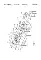
- FIG. 1is a perspective view of the loin slicer 20 of the present invention, illustrating this loin slicer in operation.
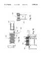
- FIG. 2is a side view of the novel blade 32 used for slicing meat in the present invention.
- FIG. 3Ashows another view of the loin slicer 20 of the present invention, wherein this view shows the side of the blade housing 28 that is hidden in FIG. 1.
- FIG. 3Bshows a cross sectional view of the blade housing 28 as viewed from cross section 3B labeled in FIG. 3A.
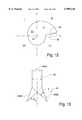
- FIG. 4shows a perspective view of the loin indexing plate 174.
- FIG. 5provides a more detailed view of the loin press 200 and the camming mechanism for iteratively holding and releasing a loin during slicing.
- FIGS. 6-11show drawings for an alternative embodiment of the present invention. In particular, these figures can be described as follows.
- FIG. 6illustrates an overall plan view of the alternative loin slicing system of the present invention.
- This figureshows a loin push bar 501, a loin holding mechanism 502, a loin in-feed conveyor 503, a control panel 504, a loin chop discharge conveyor 505, a slicer blade/guard 506, loin holding mechanism 502, having: tensioning sprockets 1000 for maintaining tension on the loin contacting belts 1001.
- FIGS. 7A, 7B and 7Cshow the top, front and side views, respectively, of the loin holding mechanism 502 and the slicer blade/guard 506.
- the labels 601-608refer respectively to a top view of the stainless steel loin conveying belt 601, the spring-loaded loin holding mechanism 602, front view of the loin conveying belt 603, apparatus framework 604, inside blade guard assembly 605, outer blade guard assembly 606, servo motor 607, and sliced product discharge conveyer 608.
- FIGS. 8A and 8Bshow the front and back of 605 and 606, respectively, of the blade guard assembly.
- FIGS. 9A and 9Bshow the front and back of an inner blade guard assembly, respectively, wherein the inner blade guard assembly resides within the outer blade guard assembly having the front and back components as illustrated in FIGS. 8A and 8B.
- FIGS. 10A, 10B and 10Cshow the top, front and side views of the loin in-feed conveyor 503, respectively.
- FIGS. 11A, 11B and 11Cshow the front, top and back views, respectively, of the tensioning sprockets 1000, these also being shown in spring-loaded loin holding mechanism in FIG. 6 as the tensioning sprockets and belts for loin holding mechanism 502.
- FIG. 12shows the blade 32 in relation to a loin 82 and normal reference axes x and y.
- FIG. 13shows a magnified view of the cutting edge 44 of the blade 32.
- FIG. 1shows a perspective view of the novel loin slicer of the present invention, wherein some portions of the loin slicer 20 have been cut away to better illustrate certain internal structures.
- the loin slicer 20includes a slicing assembly 24 that includes a disk-like blade housing 28 having a diameter of approximately 5 feet (but may vary from 2 feet to 6 feet).
- the blade housing 28includes within its interior a blade 32 that rotates on a shaft 34, wherein the shaft is coincident with the axis 36 that is normal, or substantially so, to the large disk-like vertical housing surfaces such as the surfaces 40a and 40b. Note that the blade is also shown in FIG. 2, wherein it is evident that the blade has a shell-like or involute profile with opposed surfaces 42a and 42b (FIGS.
- the blade 32varies in thickness and density, as will be described in further detail hereinbelow. Further note that the blade 32 has a center of mass that is offset from both the axis of rotation and the moment of inertia about the shaft 34 as will be described in detail hereinbelow. Thus, the blade 32 functions much like an ax or cleaver head swinging from a relatively lightweight shaft, thereby allowing the slicing force induced by the offset center of mass to enhance the slicing force applied to a bone-in loin during acceleration toward the loin.
- the blade and the shaftare rotated by a direct drive servo motor 48 (FIG. 3A) that is on the opposite side of the housing 28 from that shown in FIG. 1.
- a direct drive servo motor 48(FIG. 3A) that is on the opposite side of the housing 28 from that shown in FIG. 1.
- two blade alignment shim disks 52(FIGS. 3A and 3B) that in at least one embodiment includes a self-lubricating plastic, such as an ultra high molecular weight (UHMW) or a Delron plastic, for tightly confining the blade 32 to its intended rotational path. That is, the shim disks 52 are provided on each side of the blade 32 so that when the blade is rotated at high speed (e.g.
- the shim disksreduce blade vibrations that might cause the blade to shatter upon contact with high density bones within a pork loin and/or provide a poor cut through the pork loin by, for example, shattering the bone within a pork loin or creating a substantial amount of bone fragments that are distributed across the cut face of a pork loin slice.
- the slicing assembly 24also includes a support 54 (FIG. 3A) that has an annular blade housing cradle 56 and at least two legs 60 with extended feet 64 for firmly securing the slicing assembly 24 to the floor in a manner that tends to reduce vibrations caused by rotation of the blade 32.
- the loin slicer 20further includes a pork loin indexing and hold-down subassembly 70 that accurately controls the feeding of a bone-in pork loin (e.g., pork loin 82) to the rotating blade 32 for slicing.
- the indexing and hold-down subassembly 70includes a pork loin processing slot 74 that extends perpendicular to the face of the blade 32.
- the processing slot 74is designed to receive pork loins 82, wherein the pork loins are incrementally moved toward the blade 32 so that repeated portions can be sliced from the pork loin with an accuracy of 1/8" variation or less.
- the sidewalls 76have slanted sidewalls 76 that tend to follow the contours of a typical pork loin provided in the processing slot 74.
- the sidewalls 76are angled at a 30° angle from the horizontal.
- the bottom surface 78 upon which the majority of the pork loin 82 being processed restsmay have various contours different from the substantially flat bottom surface shown in FIG. 1.
- the bottom surface 78may be convex to thereby more easily conform to the rib curvature of the pork loins 82 being processed.
- a hinge 90that hinges a loin hold-down cover 94 to the processing slot 74.
- the loin hold-down cover 94is cut away in order to show the interior of the processing slot during the processing of the pork loin 82. That is, the loin hold-down cover 94 extends substantially over the entire processing slot 74 with the exception of a cut-out portion adjacent to the blade housing 28. That is, the cut out portion is adjacent a cutting window 98 that allows the rotating blade 32 to come in contact with a predetermined thickness of the loin 82 that is pushed through the cutting window.
- pivot attachments 108a and 108bAttached to the exterior surface of the loin hold-down cover 94 are two pivot attachments 108a and 108b. These pivot attachments have a pivot pin 112 for pivotally connecting the pivot attachments 108 to corresponding shafts 116a and 116b, respectively, wherein each shaft is part of a corresponding pneumatically, hydraulically or electrically activated cylinder assembly 124a and 124b for controlling the extension of the shafts 116 extending out from the pneumatic cylinders 128a and 128b that are also included in corresponding pneumatic cylinder assemblies 124a and 124b, respectively.
- the loin hold-down cover 94rotates about its hinge 90 to close over the processing slot 74 and any loin 82 therein for thereby securing the loin 82 on substantially all sides during processing. Conversely, when the shafts 116 recede into the pneumatic cylinders 128, the loin hold-down cover 94 rotates about hinge 90 to expose the processing slot 74.
- the pneumatic cylinder assemblies 124are secured to a slanted housing 136.
- Pneumatic hoses or lines 140connect each of the pneumatic cylinder assemblies 124 with a port (not shown) for a pneumatic controller 142 located below the processing slot 74. Accordingly, the pneumatic controller governs the air pressure provided to the pneumatic cylinder assemblies 124 for opening the loin hold-down cover 94 from the processing slot 74 and closing the loin hold-down cover 94 over the processing slot 74 to, for example, hold the loin 82 in a predetermined orientation and position for slicing with the blade 32.
- the pneumatic controller 142is signally connected to a loin slicer controller 148 that controls and monitors the processing of loins 82 by the loin slicer 20. Accordingly, the loin slicer controller 148 is also signally connected to the motor 48 for monitoring and governing the speed of this motor. More precisely, the loin slicer controller 148 is signally connected to a motor actuator provided within the housing for the motor 48 for monitoring and governing the rotation rate of the shaft 34.
- the loin slicer controller 148is also signally connected to a motor controller 154 within the housing 156 for thereby controlling a motor 155 also within the housing 156, the motor being used for rotationally extending the threaded shaft 164 from the shaft housing 168.
- the motor 155 and motor controller 154 residing within the housing 156are used to iteratively rotate the threaded shaft 164 a predetermined number of turns to thereby urge a predetermined thickness of the loin 82 through the cutting window 98 according to signals provided by the loin slicer controller 148.
- the threaded housing 168 and the threaded shaft 164instead of having the threaded housing 168 and the threaded shaft 164 extending substantially beyond the processing slot 74 (as shown in FIG.
- the loin indexing plate 174can be urged toward the blade by a linear motor that can be, for example, housed immediately underneath the bottom surface 78 wherein this bottom surface would then contain a channel (not shown) extending the length of the bottom surface and perpendicular to the blade 32.
- a slidable pushing plate(also not shown) can be provided that is slidable within the channel and operatively connected to the linear motor so that this motor can urge the slidable pushing plate toward the blade 32.
- the loin indexing platecan be appropriately indexed for urging the loin 82 toward the blade 32.
- a servo stepper motor in combination with a worm gearmay be used to urge the loin indexing plate 174 and the loin 82 toward the blade 32 as one skilled in the art will understand.
- the loin 82is held in place not only by the processing slot and the loin hold-down cover 94, but also by a loin indexing plate 174 that is attached to the threaded shaft 164 in a manner that allows the shaft 164 to rotate without rotating the loin indexing plate 174. Accordingly, the loin indexing plate 174 firmly secures the end of the loin furthest from the blade 32 from unintended movement as well as uniformly urging the loin 82 toward the blade 32 according to the actuation of the motor 155 within the housing 156. Note that the loin indexing plate 174 is shown from a different perspective in FIG. 4, wherein the face 178 of the loin indexing plate that contacts the end surface of the loin 182 is shown.
- each of the projections 182may have an expandable component that expands once the projection has entered into the end of the loin 82.
- an expandable componentcan be pneumatically, hydraulically, or electrically driven.
- the projections 182may have barbed components that are biased for expansion and can be activated for retracting. Thus, the end portion of the loin 82 through which the projections 182 extend can be easily removed by activating the barbed components to retract.
- the loin 82is also secured adjacent the cutting window by a loin press 200 that fits within the cut-out portion of the loin hold-down cover 94.
- the present embodiment of the loin press 200is also shown from a different perspective in FIG. 5. Accordingly, it should be noted that the bottom face 204 of the loin press can be concave for thereby matching a typical contour of the top of the loin 82 to which this face comes in contact. Further note that the bottom face 204 includes a plurality of projections 208 for securing the loin press to the top of the loin during a cutting operation for thereby inhibiting any undesired movement of the loin 82 when a portion thereof is being sliced off.
- a compressible housing 216Connected to the top surface 212 of the loin press 200 is a compressible housing 216 that is in turn connected to a vertical shaft 220 (best shown in FIG. 5).
- the compressible housing 216may include an enclosed compression spring 224 therein so that a downward force applied to the vertical shaft 220 can be variably applied, via the spring, through the loin press 200 to the loin 82.
- the loin press 200can accommodate and firmly hold loins of varying size and thickness due to the compressibility of the compressible housing 216 and the compression spring 224 included therein.
- the end of the vertical shaft 220 opposite the connection to the compressible housing 216is pivotally attached to pivot arm 230 via pivot assembly 234.
- the pivot arm 230is additionally attached in a middle area to a stationary shaft 238 at a pivot point 242 that allows the portions of the pivot arm 230 on each side of the stationary shaft 238 to rock or pivot in a reciprocating see-saw fashion. Accordingly, when the portion of the pivot arm 230 furthest from the shaft 220 is urged upward, then the loin press 200 is urged downward toward the loin 82. Conversely, when the portion of the pivot arm furthest from the shaft 220 is urged downward, then the loin press 200 is urged upward away from the loin 82.
- the end of the pivot arm 230 furthest from the pivot 234has a cam follower 246 attached thereto for following the cam path 250 that is recessed within the cam disk 254.
- the cam follower 246traverses the oblong cam path 250 with each rotation of the blade 32.
- the portion of the pivot arm 230 on the cam follower side of the stationary shaft 238is raised and correspondingly the loin press 200 is lowered for contacting the loin 82.
- the loin press 200is raised allowing the loin 82 to be moved forward by the loin indexing plate 74.
- the loin press 200can be synchronized with the blade for holding or pressing downward on the loin 82 just before and during the slicing of the loin by the blade 32 and then subsequently releasing the loin 82 so that the loin can be moved further towards the blade 32 for the next slicing operation.
- the loin slicer 20also includes a loin feed table 290 for loading pork loins thereon in preparation for subsequently providing these loins to the processing slot 74.
- a userprovides a loin 82 on the loin feed table 290 in an orientation substantially identical to the orientation of the loin 82 within the processing slot 74.
- a usermay then provide input to a control console such as that of the loin slicer controller 148, for activating the pneumatic controller 142 for opening the hold-down cover 94.
- a control consolefixedly attached to the loin slicer 20 and having user activatable mechanisms (e.g.
- buttons, switches, etc.) specifically designed for the operations of the loin slicer 20may be used for entering user commands, wherein the user commands can (de)activate various components of the loin slicer 20 such as: opening/closing the hold-down cover 94, activating/deactivating blade 32 rotation, and emergency stop for immediately ceasing both blade rotation and activation of motor 155. Accordingly, once the user has the loin hold-down cover 94 in an open position, the user can provide one or more loins 82 in the processing slot 74.
- the userthen supplies activation loin slicer control commands (via the loin slicer controller 148 or some alternative control console) for causing the pneumatic controller 142 to activate the pneumatic cylinder assemblies 124 so that the shafts 116 extend and thereby cause the loin hold-down cover 94 to close over the newly provided one or more loins within the processing slot 74.
- the usermay then enter loin slicer commands for activating the motor 48 so that the blade 32 and the cam disk 254 commence rotation.
- the loin slicer controller 148Once the loin slicer controller 148 has detected that the blade has reached a predetermined rotation rate about the shaft 34, and additionally has received consistent feedback as to when the blade 32 is in a position to slice a pork loin 82, the loin slicer controller 148 outputs information to the user indicating that loin slicing can commence. Accordingly, assuming that the user requests commencement of slicing, the loin slicer controller 148 synchronizes the activation of the motor 155 within the housing 156 for indexing the one or more loins 82 toward the cutting window 98 with the position of the blade cutting edge 44 so that the threaded shaft 164 rotatably extends from the shaft housing 168 only during that portion of the rotation of the blade 32 wherein the blade is entirely clear of the cutting window 98.
- the loin slicer controller 148activates the motor 155 within the housing 156 to again urge the loin 82 into the cutting window 98 in preparation for severing a next predetermined thickness of the loin from the loin 82.
- the blade 32can slice the loin 82 approximately every 0.75 seconds and that these slices are substantially free of bone dust and bone fragments due to, for example, the tightly controlled positioning and orientation of both the blade 32 and the loin 82. That is, the shim disks 52 assist in maintaining the blade 32 in an orientation that causes the cutting edge 44 of the blade 32 to enter the loin substantially perpendicular to the large primary bone residing therein. Further, the loin hold-down cover 94 and the loin press 200 facilitate in securing the loin 82 so that there is effectively no movement of the loin when the blade 32 is slicing therethrough.
- the loin 82is held securely in place within the processing slot 74 on all sides so that there is virtually no movement of the loin 82 during slicing even though the bone may have a compressive strength up to 105,000 pounds per square inch (more precisely, between 60,000 pounds per square inch and 105,000 per square inch), this being on the order of the same compressive strength of steel at an average of 120,000 pounds per square inch.
- the loin slicer blade 32has the following features:
- the moment of inertia (Io) of the blade 32is offset from the center of mass of the blade so that the blade is able to gather gravitational momentum for slicing, as will be discussed in further detail hereinbelow.
- the blade surfaces 42a and 42bare sufficiently large to effectively dampen the vibration inherent from both rotating the blade 32 and contacting the loin 82.
- the force of impact (f I ) on the loin 82is equal to the force of acceleration due to gravity (f G ), plus the force of inertia (f M ) from the motor 48 (shown in FIG. 3A).
- the motor 48is a servo motor, wherein the amperage to this motor can be varied.
- the amperage to the motor 48may be increased as needed once the loin 82 has been sliced so that the cutting edge 44 rotates about the shaft 34 until the cutting edge is in quadrant I, and more preferably, at least at an angle of 45° within this quadrant.
- the rotation of the cutting edge 44(at least through quadrants III, IV, and the initial portion of I) is at least partially due to a "flywheel" effect from the offset moment of inertia (Io). This is beneficial in that the torque on the motor 48 can be reduced during the upswing of the cutting edge 44 through quadrants IV and I.
- the motor 48can compensate for any additional inertia necessary on the upswing so long as: (load inertia)/(motor inertia) is in the range of 1.1 to 2.4, and more preferably in the range of 1.6 to 2.1. Note that if (load inertia)/(motor inertia) is greater than 2.4 (and, in many cases, greater than 2.1), the torque can quickly damage the motor 48. Relatedly, note that since the center of mass of the blade 32 is offset from the center of gravity, the motor inertia is increased by the square of this offset. This important in determining where to locate the center of mass and remain within acceptable force torque limits for the motor 48. Further note that the motor 48 may be an continuous duty servo motor having an operatively connected gear box (not shown) for assisting in reducing the torque applied to the motor 48.
- a dynamic brake(not shown) may be included for braking the blade 32 rotation if the blade begins to rotate too fast.
- a dynamic brake(not shown) may be included for braking the blade 32 rotation if the blade begins to rotate too fast.
- a dynamic brake(not shown) may be included for braking the blade 32 rotation if the blade begins to rotate too fast.
- the second moment of inertia of the blade 32 of the present embodimentis offset from the center of mass such that for "p", a point on the perimeter of the blade 32 that is furthest away from the center of mass of the blade, the second moment of inertia is 20% to 80% farther away from p. In other words, if the center of mass of the blade 32 is 8 inches from p, then the second movement of inertia will be 9.6 to 14.4 inches from p.
- a more preferred additional percentageis 25% to 40% from the center of mass instead of 20% to 80%.
- the mass of the blade and size of the servomotor required to drive the bladeare inversely related to one another for providing a given force of impact on the loin 82. For example, if a 10 pound blade is used, a 1 horsepower direct drive servo motor may be all that is required. However, if a 5 pound blade is used, the corresponding horsepower for generating the same force of impact may be three horsepower.
- the range of masses for the blademay be 1 to 15 pounds with corresponding horsepower ranges being 10 to 0.5 horsepower. In one preferred embodiment, the weight of the blade 32 is 3 to 7 pounds with motor 48 having a horsepower rating of approximately 3 to 0.5.
- the servo motor 48accelerates the angular rate of change about the blade's axis of rotation during the blade's downward slicing swing (due to, e.g., gravity assistance), and the blade deaccelerates on the upward swing (due to gravitational effects on the center of mass being offset from the rotational axis of the blade).
- at least the acceleration of the slicing swingmay be enhanced by variation of coil amperage to the motor 48 and/or increasing percentage of offset between the moment of inertia and the center of mass as discussed hereinabove.
- the force of impact of the blade 32 on the loin 82is highly variable based upon loin temperature, composition and mass, as well as blade mass and the acceleration curve of the blade.
- pork loins 82it is necessary to overcome an average bone compression strength of 105,000 lb./in. If a blade 32 of 3 to 7 pounds rotates at an average rate of 200 revolutions per minute, then such a blade can be expected to deliver between 450,000 and 900,000 lb./in. force of impact.
- the orientation of the blade 32 relative to the loin 82is such that the cutting edge 44 contacts the large loin bone in a manner to transmit the impact force substantially in a direction that the loin 82 has a substantial resistance to impact (e.g., a high point of the bone).
- the force of impact on the loin 82can be considered to be purely a compressive force.
- the blade impact forcemay be considered as a combination of compressive and shear forces.
- a key feature for successful slicing of the loin 82is the effectiveness of dampening the vibration applied to the blade 32.
- the blade 32has solid surfaces 42a and 42b for dampening blade vibration. That is, it is believed that blade 32 vibrations can be effectively dampened by having a relatively large percentage of blade surface area surrounding the shaft 34, and having this surface area contacted by vibration dampening stabilizers such as shim disks 52. More precisely, if a circle is drawn around the shaft 34, using the shaft as a center point, wherein the circle has a radius equal to the distance between this center point and the center of mass of the blade 32, then it is believed that 40% or more of the circular area must be coincident with a solid surface of the blade.
- thisprovides enough surface area to effectively dampen the blade 32 when using a self lubricating material such as UHMW or Delron plastic or other materials tightly pressed against the blade surfaces 42a and 42b.
- a dampening materialis also required at or near the blade tip to inhibit vibration.
- the blade tipis the furthest part away from the base of the shaft 34 and subject to the greatest deviations due to vibration which must be dampened.
- One embodiment of the blade 32 of the present inventionis provided from a tungsten/steel alloy of approximately: 2-3% tungsten, 0.75-1.5% chromium, 0.1 5-1.5% carbon, 0.1-0.35% silica, and the remainder being a high speed steel mixture as one skilled in the art will understand.
- the tungsten steel alloy of the blade 32has a compressive strength of approximately 450,000-900,000 pounds per square inch with a rupture strength of approximately 100,000 pounds per square inch.
- the compressive strength of the bladeis approximately seven times greater than its rupture strength, and the compressive strength is approximately seven times that of the bones within pork loins 82.
- the thickness 270due to the high strength characteristics of the tungsten steel alloy, the thickness 270 (FIG.
- the thinner blade 32may reduce bone fracturing, bone chipping, uneven cut, and/or excessive bone dust on loin slices provided with thicker blades having lower strength characteristics and therefore requiring thicker and likely blunter blades.
- zirconiumcan be impregnated into and/or coated onto the blade 32 through a process know as low temperature arc vapor deposition, as one skilled in the art will understand. That is, by inducing an arc around the y-axis (i.e., the central axis extending perpendicular to the diameter) of a zirconium cylinder, a cathodic reaction of the zirconium molecules occurs.
- the blade 32(having a steel and/or steel-tungsten alloy composition) is placed in a vacuum at 3-5 torr near the zirconium cylinder thereby allowing the molecules of the blade to fuse with the zirconium molecules deposited on the blade during the vapor deposition process.
- the new alloy created on the surfaces 42a, 42b of the blade 32has a hardness of 70-90 on the Rockwell ⁇ c ⁇ scale, thereby increasing the blade strength and wear characteristics 5 to times that of a typical blade for slicing a bone-in loin 82.
- the thickness of the blade 32 near the cutting edge 44can be reduced to within the range of 0.15 to 0.20 inches.
- the edge 44 of the blade 32has a configuration so that it functions substantially as a meat cleaver upon entering the loin 82 and subsequently also functions as a serrated knife when slicing through the non-bone portions of the loin 82.
- this dual functionality of the edge 44is provided by the offset center of mass and the acceleration curve of the blade and servo motor respectfully in conjunction with the fine serrated edges machined out in the blade edge as shown in FIG. 13.
- the serrations 2000are bent an angle of ⁇ from the axis line 2004. This angle being in the range of 5° to 30°.
- the present cutting edge 44 designincreases blade edge strength during impact and increases blade life. Note that more preferably ⁇ is 10° to 20°. Further note that “t” is approximately 0.167 inches and “S” varies between 0.1 and 0.06 inches.
- the present inventionmay also be used with a conveyor for feeding loins 82 to the blade 32.
- at least four to five sides of the portion of the loin adjacent to the cutting windowi.e., the top, bottom, and both sides of the loin and the distal end from the blade 32
- the loin 82is held in position during slicing by the following components: the bottom surface 78 and the sidewalls 76 of the slot 74 as well as by the loin hold-down cover 94, and the loin press 200 and the loin indexing plate 174.
- the loin securing componentscontact the loin 82 about the surface of the cross-section for inhibiting the movement of the loin from a preferred position. More precisely, for each angle of approximately 90° having a vertex at a center of the planar cross-section (i.e., parallel to the slicing plane) of the large bone within a pork loin 82, the angle also being in the cross-sectional plane, the loin slicer provides resistance to movement of the loin 82 in directions subtended by the angle wherein the force for movement is generally outwardly directed from the large loin bone. Further this resistance is effective against the high impact forces (e.g. up to 105,000 lbs/in 2 ) generated when the blade 32 contacts the large loin bone.
- high impact forcese.g. up to 105,000 lbs/in 2
- Such a loin chop receiving apparatusmay provide for stacking the newly sliced loin chops and/or providing each such loin chop to a conveyor for subsequent weighing and packaging thereof.
- FIGS. 6-11BThe following is a brief description of an alternative embodiment of the present invention whose components are shown in FIGS. 6-11B.
- Two main sensorsare utilized, one of these sensors is to allow the loin slicing system to sense the presence of a loin 82 before activating the pusher (e.g., a loin indexing plate 174).
- the message panelwill eventually display ⁇ Machine is Resetting Blade and Pusher ⁇ thereby indicating that the loin slicing system is nearing a "ready" status.
- an output conveyor for receiving the resulting loins slicesmust be on while the loin slicing system is in operation.
- the input conveyor for providing the loins 82 for slicingwill be energized automatically.
- the loin slicing systemwill reset the location of the blade 32 and the pusher.
- the blade edge 44must be in quadrant I (FIG. 12) and be angled 30°-40° from the x axis for start-up.
- loin slicing systemmay be equipped with multiple blades 32, select the number of blades desired for use in loin slicing.
- the loin slicing systemis developed to allow the last one to two inches of the loin to be pushed out of the system without being sliced so that these pieces can be processed separately for further processing.
- the loin slicing systemis not responding to any command:
- the blade motormight have malfunctioned.
- the Loin 82is skewed during feeding to blade:
- the Loin 82is over fed prior to slicing:
- the status of the sensorwill change only when the correct location of the loin 82 is reached.
- Widthis not consistent:
Landscapes
- Life Sciences & Earth Sciences (AREA)
- Forests & Forestry (AREA)
- Engineering & Computer Science (AREA)
- Mechanical Engineering (AREA)
- Meat, Egg Or Seafood Products (AREA)
Abstract
Description
__________________________________________________________________________ MOTORIZED CONVEYERS: 1 CONVEYOR MOTOR 1 PC VARIABLE SPEED MOTOR, Wash-down Motor, Killmorgan/IDC/Galil Control, USDA Approved 2 CONVEYOR MOTOR 1 PC SERVO MOTOR, Wash Down, Galil Control, Killmorgan USDA Approved 3 CONVEYOR MOTOR 1 PC VARIABLE SPEED MOTOR, Galil Control, Killmorgan, USDA Approved TIMING BELTS: 4 TIMING BELT 4 PCS 420H200 SINGLE SIDED l/2" PITCH 2" WIDE 42" LONG- Wash Down, JASEN UHMW/USDA 5 TIMING BELT l8 PC D390H200 DUAL-SIDE 1/2" PITCH 2" WIDE 39" Long Wash-Down, UHMW/USDA TIMING SHAFTS: 6 SHAFT, TIMING BELT PULLIES 21 PC SS, SHAFT FOR PULLIES IN CONTACT WITH MEAT SS. TENSIONERS &DRIVING PULLIES 36"/EA. 7 SHAFT, DRIVING PULLIES 5 PCS SS SHAFT CONNECTS TO SERVO MOTOR McM6112K19, P 1466 16mm 2000 mm LONG/EA BEARINGS: 8 LINEAR BALL BEARING 144 PC SS 5/8" DIA ID, McM6262K14, P 1467 9 LINEAR BALL BEARING RETAINER RINGS 290 PC BERGER, SS 1 1/8" SHAFT Q2-112 p. 476 50 pc/PKG 10 BLADE RESTRICTION R PLATE SHAFT 3 PCS SS 3/8" Dia. 36" L BERGER S1-74 11LINEAR BALL BEARINGS 28 PC McM Stainles Steel 3/8" Diam. 626K12 McM Stainless Steel 3/8" Dia. 6262K12 P. 1467 12BALL BEARINGS 156 PC Stainiess Steel 5 mm ID. 42 MM OD, 13 mm Thickness SS. Steel 15 mm ID, 42 mm OD, 13 mm THK BLADE: 13 BLADE 1 PC 62-65RC Hardened Stainless Steel, 0.160"× 36"× 12" 14 HOLE GROMMETS 100 PC McM 9600K36- Rubber, 100 Pcs/Pkg McM 9600K36 Rubber P. 2653 100 PCS/PKG 15 LARGE DIA. TFE TUBE 3 PCS McM 8556K57 5" OD × 4" ID × 6" L P. 2591 PILLOW-BLOCKS: 16 PILLOW BLOCK, 2 PCS McM 57685K17, P. 1455 For 1 1/2" Dia. Shaft 17 TEF PLATE 6 PCS McM 8545K157 3/8" × 12" × 36" 2 PCS McM 8545K47 3/8" × 24" × 24" 1 PC McM 8545K67 3/8" × 12" × 24" 18 6/6 NYLON PLATE 2 PC McM 8539K57 3/8" × 24" × 48" 1 PC McM 8539K37 3/8" × 12" × 24" INFEED CONVEYOR LOIN ARRIVAL: 19 ADJUSTABLE CONVEYOR H-STAND 2 PC McM 5766K53 18" W 31"˜37" H P. 407 20 ADJUSTABLE CONVEYOR H-STAND 2 PC McM 5766K73 30" W 31"˜37" H P. 407 21 CONVEYOR BELT 1 PC McM 6116K161 PVC 14" Wide 22 CONVEYOR BELT LASING 1 PC McM 5999K95 14" Wide Stainless Steel P. 1437 23 CONVEYOR BELT 1 PC McM 6116K166 PVC.156"THK 24" Wide. 24 CONVEYOR BELT 1PC McM 5999K95 24" Wide Stainless Steel P. 1437 25 STAINLESS STEEL SHAFT 2 PC McM 6112K22 25 mm Dia. 2000 mm L. P. 1466 26 STAINLESS STEEL SHAFT 1 PC McM 6112K6 50 mm Dia. 2000 mm L. P. 1466 27 FLANGED PILLOW 12 PC McM 58845K32 25 mm Shaft Stainless S. Steel P. 1457 28 S. STEEL CHANNEL 4 PCS 4" × l 9/16" × 3/16" 10 Ft. UPPER HOLD DOWN UNIT: 29 TOP PRESSURE ROLLER BRACKET 1 PC Stainless Steel, 10" × 24" × 3/32" 30 TOP PRESSURE YOKE 3 PCS Stainless Steel, 1/4" × 30" 31 TOP PRESSURE ROLLER SHAFT 3 PCS Stainless Steel 1/2" D × 97" L 32 TOP PRESSURE ROLLER 3 PCS UHMW, 10" D × l0" L SIDE SUPPORT: 33 SIDE RESTRICTOR PULLEY YOKE 36 PCS Stainless Steel, 4" D × 4" L 34 TENSIONER YOKE 36 PCS Stainless Steel, 4" D × 10" L 35 FRONT MOUNTNG BAR 24 PCS Stainless Steel, 2" × 24" L 36 CONNECTING BLOCK 12 PCS Stainless Steel, l2" × 36" 37 BEARING PLATE 12 PCS Stainiess Steel 48" × 24" 38 REAR SUPPORTING PLATE 12 PCS Stainless Steel, 48" × 24" 39 IDE RESTRICTOR & TENSIONER SHAFT 72 PCS Stainless Steel, 21/4" D × 32" 40 SIDE PRESSURE PLATE MOUNTING BAR 4 PCS Stainless Steel, 2" D × 36" CUTTING CONVEYOR: 41 CUTTING CONVEYOR SIDE CHANNEL 2 PCS Steel, 3 layers of enamel painting, One Hot, Two Cold Spray 42 CUTTING CONVEYOR LOWER LEG 4 PCS Steel, 3 layers of enamel painting, One Hot, Two Cold Spray 43 CUTTING CONVEYOR UPPER LEG 4 PCS Steel, 3 layers of enamel painting, One Hot, Two Cold Spray 44 SUPPORTING BRACKET 4 PCS Steel, 3 Layers of enamel painting, One Hot, Two Cold Spray 45 CONNECTING BAR 4 PCS Steel, 3 layers of enamel painting, One Hot, Two Cold Spray CONVEYOR BELT: 46 SUPPORTING BRACKET 4 PCS McM 6116K 166PVC 156" L 24" W Steel, 3 layers of enamel painting, One Hot, Two Cold Spray 47 TIMING BELT PULLEY FOLLOWER & TENSIONER 72 PCS Stainless Steel, 4" D × 4" L 48 TIMING BELT PULLEY DRIVER 12 PCS STAINLESS STEEL, 4" D × 4"L SECURITY COVERS: 49 MACHINE WHOLE COVER 2 PCS STAINLESS STEEL, SIDES 50 CONVEYOR GUIDING RAIL NO. 3 CONVEYOR 2 PCS UHMW 1/8" × 10' × 4" McM 8730K43 FDA Apprd. 51 CONVEYOR GUIDING RAIL, NO. 1 CONVEYOR 2 PCS UHMW 1/8" × 10' × 6" McM 8730K54 FDA Apprd. 52 NO.3 CONVEYOR GUIDING RAIL BRACKET 8 PCS Stainless Steel 2" W × 6" L × 1/4" 53 NO.1 CONVEYOR GUIDING RAIL BRACKET 6 PCS Stainless Steel 2" W × 12" L × 1/4" 54 CONVEYOR BELT TENSIONER ASS'Y 3 SETS UHMW Roller, Steel Slide & Spring BLADE: 55 BLADE GUIDE 1 SET 7/8" THK. Stainless Steel, and UHMW, 2 Plates, 60"D 56 BLADE ROLLERS ASS'Y 2 SETS Stainless Steel Bracket, 11/8" Dia. Roller 57 BLADE GUARD 1 PC 1"-16 Stainless Steel Bar 58 NO. 2 CUTTING CONVEYOR BELTING PRONGS Stainless Steel, 401 SS 120" L × 48" W 59 BIG DIA. TEF TOP ROLLER & BRACKET ASS'Y 3 SETS Stainless Steel, 40155 &TFE 60 SPRINGS LEE Springs, SS 0.0125 Spring Coeficient, 3/32" D × 8" L 61 BLADE MOTOR STAND 1 PC S. Steel, L-Bracket, 10" × 10" × 10" 62 LARGE TIMING BELT PULLEY: 26 PCS Stainless Steel, 1/2" Pitch, 19 Grooves, 3.25" Dia. 63 SMALL TIMING BELT PULLEY: 72 PCS Stainless Steel, 1/2" Pitch, 16 Grooves. 2.50" Dia. BLADE MOTOR: 68 BLADE SERVO MOTOR 1 PC SERVO MOTOR, IDC, Killmorgen, USDA Wash-Down 69 CHOPPING BLOCK SUPPORTING LEGS (BACK) 2 PCS S. Steel, 32" × 4"Square 70 CHOPPING BLOCK SUPPORTING LEGS (FRONT) 2 PCS S. Steel, 32" × 4" Square 71 CHOPPING BLOCK (FRONT) 1 PC S. Steel, 2" × 2" × 8" 72 CHOPPING BLOCK (BACK) 1 PC S. Steel, 2" × 2" × 8" 73 SLIDING SHOULDER SCREW 2 PCS S. Steel, 7" L × 11/4" D PUSHER ASSEMBLY: 74 Pusher Assembly 1 PC 108" Indexing System, High Speed Bet Driven, 5 m/s IDC Indexing, IDC Driver, IDC Controller 75 Front UHMW Head 1 4" × 4",Stainless Steel Tubing 76 Limit Switch, Home position 1 IDC Sensor Magnetic, 5-30 VDC 77 Limit Switch, Max. Travel 1 IDC Sensor Magnetic, 5-30VDC 78 Loin Arrival, Optical Sensor 1 Keyence, Opticai Sensor, 5-30 VDC 79 Loin Shieid 1 Stanless Steel, 401, 36" × 12" × 1/16" 80 Slice Chute 1 Stainless Steel 1/16" Thick __________________________________________________________________________
Claims (29)
Priority Applications (1)
| Application Number | Priority Date | Filing Date | Title |
|---|---|---|---|
| US09/018,509US5989116A (en) | 1998-02-03 | 1998-02-03 | High-speed bone-in loin slicer |
Applications Claiming Priority (1)
| Application Number | Priority Date | Filing Date | Title |
|---|---|---|---|
| US09/018,509US5989116A (en) | 1998-02-03 | 1998-02-03 | High-speed bone-in loin slicer |
Publications (1)
| Publication Number | Publication Date |
|---|---|
| US5989116Atrue US5989116A (en) | 1999-11-23 |
Family
ID=21788286
Family Applications (1)
| Application Number | Title | Priority Date | Filing Date |
|---|---|---|---|
| US09/018,509Expired - Fee RelatedUS5989116A (en) | 1998-02-03 | 1998-02-03 | High-speed bone-in loin slicer |
Country Status (1)
| Country | Link |
|---|---|
| US (1) | US5989116A (en) |
Cited By (81)
| Publication number | Priority date | Publication date | Assignee | Title |
|---|---|---|---|---|
| US20020017178A1 (en)* | 2000-08-14 | 2002-02-14 | Gass Stephen F. | Motion detecting system for use in a safety system for power equipment |
| WO2004078431A1 (en)* | 2003-03-04 | 2004-09-16 | Cfs Kempten Gmbh | Method and device for cutting food, whereby the rotary speed and/or the rotary direction of the blade and/or the rotor are adjusted |
| US6857345B2 (en) | 2000-08-14 | 2005-02-22 | Sd3, Llc | Brake positioning system |
| US6877410B2 (en) | 2000-09-29 | 2005-04-12 | Sd3, Llc | Miter saw with improved safety system |
| US20050132854A1 (en)* | 2001-10-26 | 2005-06-23 | Mark Kovacs | Slicer carriage tracking arrangement and associated method of controlling food product carriage |
| US6920814B2 (en) | 2000-08-14 | 2005-07-26 | Sd3, Llc | Cutting tool safety system |
| US6945149B2 (en) | 2001-07-25 | 2005-09-20 | Sd3, Llc | Actuators for use in fast-acting safety systems |
| US20060021487A1 (en)* | 2004-07-30 | 2006-02-02 | William Dickover | Serrated blade for slicing machine |
| US6997090B2 (en) | 2001-08-13 | 2006-02-14 | Sd3, Llc | Safety systems for power equipment |
| US7024975B2 (en) | 2000-08-14 | 2006-04-11 | Sd3, Llc | Brake mechanism for power equipment |
| US7055417B1 (en) | 1999-10-01 | 2006-06-06 | Sd3, Llc | Safety system for power equipment |
| US7100483B2 (en) | 2000-08-14 | 2006-09-05 | Sd3, Llc | Firing subsystem for use in a fast-acting safety system |
| EP1704973A1 (en)* | 2005-03-22 | 2006-09-27 | Uwe Dipl.-Ing. Reifenhäuser | Method and apparatus for slicing elongated food products |
| US7137326B2 (en) | 2000-08-14 | 2006-11-21 | Sd3, Llc | Translation stop for use in power equipment |
| US7171879B2 (en) | 2001-07-02 | 2007-02-06 | Sd3, Llc | Discrete proximity detection system |
| US7210383B2 (en) | 2000-08-14 | 2007-05-01 | Sd3, Llc | Detection system for power equipment |
| WO2007002819A3 (en)* | 2005-06-29 | 2007-06-28 | Premark Feg Llc | Programmable slicer with powered food carriage |
| US7284467B2 (en) | 2000-08-14 | 2007-10-23 | Sd3, Llc | Apparatus and method for detecting dangerous conditions in power equipment |
| US7290472B2 (en) | 2002-01-14 | 2007-11-06 | Sd3, Llc | Miter saw with improved safety system |
| US7308843B2 (en) | 2000-08-14 | 2007-12-18 | Sd3, Llc | Spring-biased brake mechanism for power equipment |
| US7347851B1 (en) | 2004-03-09 | 2008-03-25 | Leo B Kriksunov | Needleless hypodermic jet injector apparatus and method |
| US7350445B2 (en) | 2003-08-20 | 2008-04-01 | Sd3, Llc | Brake cartridge for power equipment |
| US7350444B2 (en) | 2000-08-14 | 2008-04-01 | Sd3, Llc | Table saw with improved safety system |
| US7353737B2 (en) | 2001-08-13 | 2008-04-08 | Sd3, Llc | Miter saw with improved safety system |
| US7357056B2 (en) | 2000-09-29 | 2008-04-15 | Sd3, Llc | Cutting tool safety system |
| US7359174B2 (en) | 2000-08-14 | 2008-04-15 | Sd3, Llc | Motion detecting system for use in a safety system for power equipment |
| US20080190305A1 (en)* | 2005-08-12 | 2008-08-14 | Premark Feg L.L.C. | Food Product Slicer Wtih Carriage Drive |
| EP1958742A1 (en)* | 2007-02-15 | 2008-08-20 | AEW Delford Systems Limited | Holding down food products in slicing machines |
| US7421315B2 (en) | 2001-11-13 | 2008-09-02 | Sd3, Llc | Detection system for power equipment |
| US7472634B2 (en) | 2003-08-20 | 2009-01-06 | Sd3, Llc | Woodworking machines with overmolded arbors |
| US7481140B2 (en) | 2005-04-15 | 2009-01-27 | Sd3, Llc | Detection systems for power equipment |
| US7509899B2 (en) | 2000-08-14 | 2009-03-31 | Sd3, Llc | Retraction system for use in power equipment |
| US20090120256A1 (en)* | 2007-10-22 | 2009-05-14 | Pasek James E | Food Article Feed Apparatus for a Food Article Slicing Machine |
| US7536238B2 (en) | 2003-12-31 | 2009-05-19 | Sd3, Llc | Detection systems for power equipment |
| US7600455B2 (en) | 2000-08-14 | 2009-10-13 | Sd3, Llc | Logic control for fast-acting safety system |
| DE102008019776A1 (en)* | 2008-04-18 | 2009-10-22 | CFS Bühl GmbH | Method, device and knife for slicing food |
| US7621205B2 (en) | 1999-10-01 | 2009-11-24 | Sd3, Llc | Band saw with safety system |
| US7707920B2 (en) | 2003-12-31 | 2010-05-04 | Sd3, Llc | Table saws with safety systems |
| US7712403B2 (en) | 2001-07-03 | 2010-05-11 | Sd3, Llc | Actuators for use in fast-acting safety systems |
| US20100116107A1 (en)* | 2008-11-10 | 2010-05-13 | Ross Industries, Inc. | Apparatus and method for efficient smear-less slicing of meat, poultry and similar food products |
| US7784507B2 (en) | 2000-09-29 | 2010-08-31 | Sd3, Llc | Router with improved safety system |
| US7827890B2 (en) | 2004-01-29 | 2010-11-09 | Sd3, Llc | Table saws with safety systems and systems to mount and index attachments |
| DE102009020633A1 (en)* | 2009-05-09 | 2010-11-11 | Bizerba Gmbh & Co. Kg | Slicer for e.g. meat, has circular knife driven for separating slices of food strand, and feed device feeding food strand by electric linear motor in driven manner and comprising feed arm, which is connected with rotor of linear motor |
| US7836804B2 (en) | 2003-08-20 | 2010-11-23 | Sd3, Llc | Woodworking machines with overmolded arbors |
| US20110162496A1 (en)* | 2009-11-12 | 2011-07-07 | Uwe Reifenhaeuser | Method and device for cutting a bone containing material string into slices |
| US8065943B2 (en) | 2000-09-18 | 2011-11-29 | Sd3, Llc | Translation stop for use in power equipment |
| EP2359992A3 (en)* | 2010-02-24 | 2011-12-28 | Uwe Reifenhäuser | Machine for cutting elongated food |
| US8100039B2 (en) | 2000-08-14 | 2012-01-24 | Sd3, Llc | Miter saw with safety system |
| US8186255B2 (en) | 2000-09-29 | 2012-05-29 | Sd3, Llc | Contact detection system for power equipment |
| US20120174722A1 (en)* | 2009-06-25 | 2012-07-12 | Weber Maschinenbau Gmbh Breidenbach | Cutting blade |
| EP2543485A1 (en)* | 2011-07-08 | 2013-01-09 | Weber Maschinenbau GmbH Breidenbach | Device for cutting a food product |
| US20130068076A1 (en)* | 2010-06-11 | 2013-03-21 | Cfs Buhl Gmbh | Method and device for adjusting the cutting gap of slicing device |
| EP2153950A3 (en)* | 2008-08-16 | 2013-03-27 | Bizerba GmbH & Co. KG | Cutting machine for food |
| US20130133498A1 (en)* | 2010-08-13 | 2013-05-30 | Bizerba Gmbh & Co. Kg | Slicer |
| US8459157B2 (en) | 2003-12-31 | 2013-06-11 | Sd3, Llc | Brake cartridges and mounting systems for brake cartridges |
| US20150135915A1 (en)* | 2013-11-15 | 2015-05-21 | C. & E. Fein Gmbh | Saw Blade For An Oscillatingly Driven Saw |
| US20160303669A1 (en)* | 2015-04-20 | 2016-10-20 | HE&M Inc. | Band saw blade sensor and control system |
| CN106078865A (en)* | 2016-06-28 | 2016-11-09 | 刘凡 | A kind of fresh meat slicer device people |
| US9724840B2 (en) | 1999-10-01 | 2017-08-08 | Sd3, Llc | Safety systems for power equipment |
| US9737942B2 (en) | 2012-04-05 | 2017-08-22 | Weber Maschinenbau Gmbh Breidenbach | Interface between knife and knife holder |
| CN108262787A (en)* | 2017-12-08 | 2018-07-10 | 浙江工业大学之江学院 | A kind of automatic clinical microtome |
| CN108312212A (en)* | 2018-02-27 | 2018-07-24 | 广东知识城运营服务有限公司 | A kind of slicing device |
| CN108466298A (en)* | 2018-03-14 | 2018-08-31 | 赣州市万研教育咨询有限公司 | A kind of gynemetrics puerpera fruit of a cubeb litsea tree trunk cutting equipment |
| CN108544555A (en)* | 2018-05-11 | 2018-09-18 | 鄢仁明 | A kind of internal medicine detection Chinese medicinal material slicing device |
| US10118308B2 (en) | 2013-10-17 | 2018-11-06 | Sawstop Holding Llc | Systems to mount and index riving knives and spreaders in table saws |
| JP2018183831A (en)* | 2017-04-25 | 2018-11-22 | 株式会社なんつね | Chop cutter |
| CN109049076A (en)* | 2018-08-30 | 2018-12-21 | 赵爱 | Automatic sugarcane cutting machine |
| CN109176631A (en)* | 2018-07-17 | 2019-01-11 | 常州信息职业技术学院 | Electric automatization slicer |
| CN109483622A (en)* | 2018-10-10 | 2019-03-19 | 安徽源和堂药业股份有限公司 | A kind of processing of herbal decoction piece is with chopping medicine machine |
| CN110465980A (en)* | 2019-09-09 | 2019-11-19 | 安庆万草千木农业科技有限公司 | A kind of intelligent Chinese medicine material slice batch charging mechanism and feeding method |
| CN110744631A (en)* | 2019-10-25 | 2020-02-04 | 徐州鼎元机械有限公司 | Intelligent plastic cutting equipment for automobile part production |
| CN110840638A (en)* | 2019-11-28 | 2020-02-28 | 四川大学华西医院 | A cartilage slicer for plastic surgery |
| CN111098347A (en)* | 2019-11-25 | 2020-05-05 | 重庆德庄农产品开发有限公司 | Tripe shred device |
| CN111300508A (en)* | 2020-03-09 | 2020-06-19 | 江西竹海农业发展有限公司 | High-efficient section device of bamboo shoots processing of thunder |
| US10703003B2 (en)* | 2014-01-24 | 2020-07-07 | Smithfield Foods, Inc. | Method and apparatus for spiral ham slicing |
| CN111844185A (en)* | 2020-05-28 | 2020-10-30 | 亳州市楚王制药机械制造有限公司 | Stepless speed regulation slicing machine |
| CN111873028A (en)* | 2020-07-14 | 2020-11-03 | 王发云 | Plantain core section device |
| CN112025805A (en)* | 2020-08-25 | 2020-12-04 | 山东工业职业学院 | Electric automatization slicer |
| CN115302558A (en)* | 2022-06-01 | 2022-11-08 | 集美大学 | A mechanical variable speed and automatic compression feeding rhizome slicer |
| US12208194B2 (en) | 2018-06-13 | 2025-01-28 | Stryker European Operations Limited | Bone fragment collector and processor |
| US12274629B2 (en) | 2019-12-18 | 2025-04-15 | Stryker European Operations Limited | Bone fragment collector and processor |
Citations (4)
| Publication number | Priority date | Publication date | Assignee | Title |
|---|---|---|---|---|
| US4181053A (en)* | 1976-06-29 | 1980-01-01 | Danepak Ltd. | Food slicers |
| US4273013A (en)* | 1979-07-09 | 1981-06-16 | Sunbeam Corporation | Slicing machine |
| US4312252A (en)* | 1976-05-25 | 1982-01-26 | Danepak Ltd. | Food slicers |
| US5862730A (en)* | 1997-01-17 | 1999-01-26 | Premark Feg L.L.C. | Slicer with staged dynamic braking system |
- 1998
- 1998-02-03USUS09/018,509patent/US5989116A/ennot_activeExpired - Fee Related
Patent Citations (4)
| Publication number | Priority date | Publication date | Assignee | Title |
|---|---|---|---|---|
| US4312252A (en)* | 1976-05-25 | 1982-01-26 | Danepak Ltd. | Food slicers |
| US4181053A (en)* | 1976-06-29 | 1980-01-01 | Danepak Ltd. | Food slicers |
| US4273013A (en)* | 1979-07-09 | 1981-06-16 | Sunbeam Corporation | Slicing machine |
| US5862730A (en)* | 1997-01-17 | 1999-01-26 | Premark Feg L.L.C. | Slicer with staged dynamic braking system |
Cited By (139)
| Publication number | Priority date | Publication date | Assignee | Title |
|---|---|---|---|---|
| US8196499B2 (en) | 1999-10-01 | 2012-06-12 | Sd3, Llc | Power equipment with detection and reaction systems |
| US8408106B2 (en) | 1999-10-01 | 2013-04-02 | Sd3, Llc | Method of operating power equipment with detection and reaction systems |
| US7621205B2 (en) | 1999-10-01 | 2009-11-24 | Sd3, Llc | Band saw with safety system |
| US9969014B2 (en) | 1999-10-01 | 2018-05-15 | Sawstop Holding Llc | Power equipment with detection and reaction systems |
| US9925683B2 (en) | 1999-10-01 | 2018-03-27 | Sawstop Holding Llc | Table saws |
| US7788999B2 (en) | 1999-10-01 | 2010-09-07 | Sd3, Llc | Brake mechanism for power equipment |
| US9724840B2 (en) | 1999-10-01 | 2017-08-08 | Sd3, Llc | Safety systems for power equipment |
| US9522476B2 (en) | 1999-10-01 | 2016-12-20 | Sd3, Llc | Power equipment with detection and reaction systems |
| US7525055B2 (en) | 1999-10-01 | 2009-04-28 | Sd3, Llc | Switch box for power tools with safety systems |
| US7895927B2 (en) | 1999-10-01 | 2011-03-01 | Sd3, Llc | Power equipment with detection and reaction systems |
| US7055417B1 (en) | 1999-10-01 | 2006-06-06 | Sd3, Llc | Safety system for power equipment |
| US7347131B2 (en) | 1999-10-01 | 2008-03-25 | Sd3, Llc | Miter saw with improved safety system |
| US10335972B2 (en) | 1999-10-01 | 2019-07-02 | Sawstop Holding Llc | Table Saws |
| US7509899B2 (en) | 2000-08-14 | 2009-03-31 | Sd3, Llc | Retraction system for use in power equipment |
| US6920814B2 (en) | 2000-08-14 | 2005-07-26 | Sd3, Llc | Cutting tool safety system |
| US7210383B2 (en) | 2000-08-14 | 2007-05-01 | Sd3, Llc | Detection system for power equipment |
| US8100039B2 (en) | 2000-08-14 | 2012-01-24 | Sd3, Llc | Miter saw with safety system |
| US7228772B2 (en) | 2000-08-14 | 2007-06-12 | Sd3, Llc | Brake positioning system |
| US8522655B2 (en) | 2000-08-14 | 2013-09-03 | Sd3, Llc | Logic control for fast-acting safety system |
| US8371196B2 (en) | 2000-08-14 | 2013-02-12 | Sd3, Llc | Motion detecting system for use in a safety system for power equipment |
| US7350444B2 (en) | 2000-08-14 | 2008-04-01 | Sd3, Llc | Table saw with improved safety system |
| US7308843B2 (en) | 2000-08-14 | 2007-12-18 | Sd3, Llc | Spring-biased brake mechanism for power equipment |
| US8191450B2 (en) | 2000-08-14 | 2012-06-05 | Sd3, Llc | Power equipment with detection and reaction systems |
| US7100483B2 (en) | 2000-08-14 | 2006-09-05 | Sd3, Llc | Firing subsystem for use in a fast-acting safety system |
| US6857345B2 (en) | 2000-08-14 | 2005-02-22 | Sd3, Llc | Brake positioning system |
| US7284467B2 (en) | 2000-08-14 | 2007-10-23 | Sd3, Llc | Apparatus and method for detecting dangerous conditions in power equipment |
| US8151675B2 (en) | 2000-08-14 | 2012-04-10 | Sd3, Llc | Logic control for fast-acting safety system |
| US7137326B2 (en) | 2000-08-14 | 2006-11-21 | Sd3, Llc | Translation stop for use in power equipment |
| US7359174B2 (en) | 2000-08-14 | 2008-04-15 | Sd3, Llc | Motion detecting system for use in a safety system for power equipment |
| US20020017178A1 (en)* | 2000-08-14 | 2002-02-14 | Gass Stephen F. | Motion detecting system for use in a safety system for power equipment |
| US8051759B2 (en) | 2000-08-14 | 2011-11-08 | Sd3, Llc | Motion detecting system for use in a safety system for power equipment |
| US7921754B2 (en) | 2000-08-14 | 2011-04-12 | Sd3, Llc | Logic control for fast-acting safety system |
| US7024975B2 (en) | 2000-08-14 | 2006-04-11 | Sd3, Llc | Brake mechanism for power equipment |
| US7832314B2 (en) | 2000-08-14 | 2010-11-16 | Sd3, Llc | Brake positioning system |
| US20100251866A1 (en)* | 2000-08-14 | 2010-10-07 | Gass Stephen F | Motion detecting system for use in a safety system for power equipment |
| US7600455B2 (en) | 2000-08-14 | 2009-10-13 | Sd3, Llc | Logic control for fast-acting safety system |
| US9038515B2 (en) | 2000-08-14 | 2015-05-26 | Sd3, Llc | Logic control for fast-acting safety system |
| US7225712B2 (en)* | 2000-08-14 | 2007-06-05 | Sd3, Llc | Motion detecting system for use in a safety system for power equipment |
| US7681479B2 (en) | 2000-08-14 | 2010-03-23 | Sd3, Llc | Motion detecting system for use in a safety system for power equipment |
| US8065943B2 (en) | 2000-09-18 | 2011-11-29 | Sd3, Llc | Translation stop for use in power equipment |
| US8061245B2 (en) | 2000-09-29 | 2011-11-22 | Sd3, Llc | Safety methods for use in power equipment |
| US7784507B2 (en) | 2000-09-29 | 2010-08-31 | Sd3, Llc | Router with improved safety system |
| US8186255B2 (en) | 2000-09-29 | 2012-05-29 | Sd3, Llc | Contact detection system for power equipment |
| US7357056B2 (en) | 2000-09-29 | 2008-04-15 | Sd3, Llc | Cutting tool safety system |
| US6877410B2 (en) | 2000-09-29 | 2005-04-12 | Sd3, Llc | Miter saw with improved safety system |
| US7171879B2 (en) | 2001-07-02 | 2007-02-06 | Sd3, Llc | Discrete proximity detection system |
| US7591210B2 (en) | 2001-07-02 | 2009-09-22 | Sd3, Llc | Discrete proximity detection system |
| US7712403B2 (en) | 2001-07-03 | 2010-05-11 | Sd3, Llc | Actuators for use in fast-acting safety systems |
| US6945149B2 (en) | 2001-07-25 | 2005-09-20 | Sd3, Llc | Actuators for use in fast-acting safety systems |
| US7353737B2 (en) | 2001-08-13 | 2008-04-08 | Sd3, Llc | Miter saw with improved safety system |
| US6997090B2 (en) | 2001-08-13 | 2006-02-14 | Sd3, Llc | Safety systems for power equipment |
| US7398718B2 (en)* | 2001-10-26 | 2008-07-15 | Premark Feg L.L.C. | Method for controlling a slicing operation |
| US20050132854A1 (en)* | 2001-10-26 | 2005-06-23 | Mark Kovacs | Slicer carriage tracking arrangement and associated method of controlling food product carriage |
| US7421315B2 (en) | 2001-11-13 | 2008-09-02 | Sd3, Llc | Detection system for power equipment |
| US7290472B2 (en) | 2002-01-14 | 2007-11-06 | Sd3, Llc | Miter saw with improved safety system |
| WO2004078431A1 (en)* | 2003-03-04 | 2004-09-16 | Cfs Kempten Gmbh | Method and device for cutting food, whereby the rotary speed and/or the rotary direction of the blade and/or the rotor are adjusted |
| US7472634B2 (en) | 2003-08-20 | 2009-01-06 | Sd3, Llc | Woodworking machines with overmolded arbors |
| US7350445B2 (en) | 2003-08-20 | 2008-04-01 | Sd3, Llc | Brake cartridge for power equipment |
| US7836804B2 (en) | 2003-08-20 | 2010-11-23 | Sd3, Llc | Woodworking machines with overmolded arbors |
| US7866239B2 (en) | 2003-12-31 | 2011-01-11 | Sd3, Llc | Elevation mechanism for table saws |
| US8498732B2 (en) | 2003-12-31 | 2013-07-30 | Sd3, Llc | Detection systems for power equipment |
| US20170312837A1 (en)* | 2003-12-31 | 2017-11-02 | Sd3, Llc | Table saws |
| US7707920B2 (en) | 2003-12-31 | 2010-05-04 | Sd3, Llc | Table saws with safety systems |
| US8459157B2 (en) | 2003-12-31 | 2013-06-11 | Sd3, Llc | Brake cartridges and mounting systems for brake cartridges |
| US9623498B2 (en) | 2003-12-31 | 2017-04-18 | Sd3, Llc | Table saws |
| US8122807B2 (en) | 2003-12-31 | 2012-02-28 | Sd3, Llc | Table saws with safety systems |
| US8489223B2 (en) | 2003-12-31 | 2013-07-16 | Sd3, Llc | Detection systems for power equipment |
| US7991503B2 (en) | 2003-12-31 | 2011-08-02 | Sd3, Llc | Detection systems for power equipment |
| US10442108B2 (en)* | 2003-12-31 | 2019-10-15 | Sawstop Holding Llc | Table saws |
| US7536238B2 (en) | 2003-12-31 | 2009-05-19 | Sd3, Llc | Detection systems for power equipment |
| US8087438B2 (en) | 2003-12-31 | 2012-01-03 | Sd3, Llc | Detection systems for power equipment |
| US7827893B2 (en) | 2003-12-31 | 2010-11-09 | Sd3, Llc | Elevation mechanism for table saws |
| US10052786B2 (en) | 2004-01-29 | 2018-08-21 | Sawstop Holding Llc | Table saws with safety systems and systems to mount and index attachments |
| US7827890B2 (en) | 2004-01-29 | 2010-11-09 | Sd3, Llc | Table saws with safety systems and systems to mount and index attachments |
| US8505424B2 (en) | 2004-01-29 | 2013-08-13 | Sd3, Llc | Table saws with safety systems and systems to mount and index attachments |
| US10882207B2 (en) | 2004-01-29 | 2021-01-05 | Sawstop Holding Llc | Table saws with safety systems and systems to mount and index attachments |
| US7347851B1 (en) | 2004-03-09 | 2008-03-25 | Leo B Kriksunov | Needleless hypodermic jet injector apparatus and method |
| US20060021487A1 (en)* | 2004-07-30 | 2006-02-02 | William Dickover | Serrated blade for slicing machine |
| EP1704973A1 (en)* | 2005-03-22 | 2006-09-27 | Uwe Dipl.-Ing. Reifenhäuser | Method and apparatus for slicing elongated food products |
| US7481140B2 (en) | 2005-04-15 | 2009-01-27 | Sd3, Llc | Detection systems for power equipment |
| US20090211417A1 (en)* | 2005-06-29 | 2009-08-27 | Premark Feg L.L.C. | Programmable Slicer With Powered Food Carriage |
| WO2007002819A3 (en)* | 2005-06-29 | 2007-06-28 | Premark Feg Llc | Programmable slicer with powered food carriage |
| US20110162498A1 (en)* | 2005-06-29 | 2011-07-07 | Rummel Samuel A | Progammable slicer with powered food carriage |
| AU2006263634B2 (en)* | 2005-06-29 | 2011-01-20 | Premark Feg L.L.C. | Programmable slicer with powered food carriage |
| US20080190305A1 (en)* | 2005-08-12 | 2008-08-14 | Premark Feg L.L.C. | Food Product Slicer Wtih Carriage Drive |
| EP1958742A1 (en)* | 2007-02-15 | 2008-08-20 | AEW Delford Systems Limited | Holding down food products in slicing machines |
| US20090188358A1 (en)* | 2007-10-22 | 2009-07-30 | David Hansen | Output Conveyor for a Food Article Slicing Machine |
| US8616103B2 (en)* | 2007-10-22 | 2013-12-31 | Formax, Inc | Knife blade retraction mechanism for a food article slicing machine |
| US20090120256A1 (en)* | 2007-10-22 | 2009-05-14 | Pasek James E | Food Article Feed Apparatus for a Food Article Slicing Machine |
| US20090173196A1 (en)* | 2007-10-22 | 2009-07-09 | Lindee Scott A | Maintenance and Safety System for a Food Article Slicing Machine |
| US20090151527A1 (en)* | 2007-10-22 | 2009-06-18 | Lindee Scott A | Knife Blade Retraction Mechanism for a Food Article Slicing Machine |
| US8549966B2 (en) | 2007-10-22 | 2013-10-08 | Formax, Inc. | Output conveyor for a food article slicing machine |
| US20090188357A1 (en)* | 2007-10-22 | 2009-07-30 | Lindee Scott A | Information Carrier System for a Food Article Slicing Machine |
| US8978529B2 (en) | 2007-10-22 | 2015-03-17 | Formax, Inc. | Food article feed apparatus for a food article slicing machine |
| US8850938B2 (en) | 2007-10-22 | 2014-10-07 | Formax, Inc. | Maintenance and safety system for a food article slicing machine |
| US9272428B2 (en) | 2008-04-18 | 2016-03-01 | Gea Food Solutions Germany Gmbh | Method, device and measuring device for cutting open foodstuff |
| DE102008019776A1 (en)* | 2008-04-18 | 2009-10-22 | CFS Bühl GmbH | Method, device and knife for slicing food |
| EP2153950A3 (en)* | 2008-08-16 | 2013-03-27 | Bizerba GmbH & Co. KG | Cutting machine for food |
| US20100116107A1 (en)* | 2008-11-10 | 2010-05-13 | Ross Industries, Inc. | Apparatus and method for efficient smear-less slicing of meat, poultry and similar food products |
| WO2010054332A3 (en)* | 2008-11-10 | 2010-07-08 | Ross Industries, Inc. | Apparatus and method for efficient smear-less slicing of meat, poultry and similar food products |
| DE102009020633A1 (en)* | 2009-05-09 | 2010-11-11 | Bizerba Gmbh & Co. Kg | Slicer for e.g. meat, has circular knife driven for separating slices of food strand, and feed device feeding food strand by electric linear motor in driven manner and comprising feed arm, which is connected with rotor of linear motor |
| US20120174722A1 (en)* | 2009-06-25 | 2012-07-12 | Weber Maschinenbau Gmbh Breidenbach | Cutting blade |
| US20110162496A1 (en)* | 2009-11-12 | 2011-07-07 | Uwe Reifenhaeuser | Method and device for cutting a bone containing material string into slices |
| US8584562B2 (en)* | 2009-11-12 | 2013-11-19 | Uwe Reifenhaeuser | Method and device for cutting a bone containing material string into slices |
| EP2359992A3 (en)* | 2010-02-24 | 2011-12-28 | Uwe Reifenhäuser | Machine for cutting elongated food |
| US20130068076A1 (en)* | 2010-06-11 | 2013-03-21 | Cfs Buhl Gmbh | Method and device for adjusting the cutting gap of slicing device |
| US9815218B2 (en)* | 2010-08-13 | 2017-11-14 | Bizerba Gmbh & Co. Kg | Slicer with pulse-width modulation control unit |
| US20130133498A1 (en)* | 2010-08-13 | 2013-05-30 | Bizerba Gmbh & Co. Kg | Slicer |
| EP2543485A1 (en)* | 2011-07-08 | 2013-01-09 | Weber Maschinenbau GmbH Breidenbach | Device for cutting a food product |
| US9962782B2 (en) | 2012-04-05 | 2018-05-08 | Weber Maschinenbau Gmbh Breidenbach | Interface between knife and knife holder |
| US9737942B2 (en) | 2012-04-05 | 2017-08-22 | Weber Maschinenbau Gmbh Breidenbach | Interface between knife and knife holder |
| US10118308B2 (en) | 2013-10-17 | 2018-11-06 | Sawstop Holding Llc | Systems to mount and index riving knives and spreaders in table saws |
| US20150135915A1 (en)* | 2013-11-15 | 2015-05-21 | C. & E. Fein Gmbh | Saw Blade For An Oscillatingly Driven Saw |
| US10220539B2 (en)* | 2013-11-15 | 2019-03-05 | C. & E. Fein Gmbh | Saw blade for an oscillatingly driven saw |
| US10703003B2 (en)* | 2014-01-24 | 2020-07-07 | Smithfield Foods, Inc. | Method and apparatus for spiral ham slicing |
| US9902000B2 (en)* | 2015-04-20 | 2018-02-27 | HE&M Inc. | Band saw blade sensor and control system |
| US20160303669A1 (en)* | 2015-04-20 | 2016-10-20 | HE&M Inc. | Band saw blade sensor and control system |
| CN106078865A (en)* | 2016-06-28 | 2016-11-09 | 刘凡 | A kind of fresh meat slicer device people |
| JP2018183831A (en)* | 2017-04-25 | 2018-11-22 | 株式会社なんつね | Chop cutter |
| CN108262787A (en)* | 2017-12-08 | 2018-07-10 | 浙江工业大学之江学院 | A kind of automatic clinical microtome |
| CN108312212A (en)* | 2018-02-27 | 2018-07-24 | 广东知识城运营服务有限公司 | A kind of slicing device |
| CN108466298B (en)* | 2018-03-14 | 2020-02-11 | 齐广涛 | Gynaecology and obstetrics's obstetrics is with litsea cubeba trunk cutting equipment |
| CN108466298A (en)* | 2018-03-14 | 2018-08-31 | 赣州市万研教育咨询有限公司 | A kind of gynemetrics puerpera fruit of a cubeb litsea tree trunk cutting equipment |
| CN108544555B (en)* | 2018-05-11 | 2020-12-25 | 青岛市市立医院 | Internal medicine detects with chinese-medicinal material section device |
| CN108544555A (en)* | 2018-05-11 | 2018-09-18 | 鄢仁明 | A kind of internal medicine detection Chinese medicinal material slicing device |
| US12208194B2 (en) | 2018-06-13 | 2025-01-28 | Stryker European Operations Limited | Bone fragment collector and processor |
| CN109176631A (en)* | 2018-07-17 | 2019-01-11 | 常州信息职业技术学院 | Electric automatization slicer |
| CN109049076A (en)* | 2018-08-30 | 2018-12-21 | 赵爱 | Automatic sugarcane cutting machine |
| CN109483622A (en)* | 2018-10-10 | 2019-03-19 | 安徽源和堂药业股份有限公司 | A kind of processing of herbal decoction piece is with chopping medicine machine |
| CN110465980A (en)* | 2019-09-09 | 2019-11-19 | 安庆万草千木农业科技有限公司 | A kind of intelligent Chinese medicine material slice batch charging mechanism and feeding method |
| CN110744631A (en)* | 2019-10-25 | 2020-02-04 | 徐州鼎元机械有限公司 | Intelligent plastic cutting equipment for automobile part production |
| CN111098347A (en)* | 2019-11-25 | 2020-05-05 | 重庆德庄农产品开发有限公司 | Tripe shred device |
| CN110840638A (en)* | 2019-11-28 | 2020-02-28 | 四川大学华西医院 | A cartilage slicer for plastic surgery |
| US12274629B2 (en) | 2019-12-18 | 2025-04-15 | Stryker European Operations Limited | Bone fragment collector and processor |
| CN111300508A (en)* | 2020-03-09 | 2020-06-19 | 江西竹海农业发展有限公司 | High-efficient section device of bamboo shoots processing of thunder |
| CN111844185A (en)* | 2020-05-28 | 2020-10-30 | 亳州市楚王制药机械制造有限公司 | Stepless speed regulation slicing machine |
| CN111873028A (en)* | 2020-07-14 | 2020-11-03 | 王发云 | Plantain core section device |
| CN112025805A (en)* | 2020-08-25 | 2020-12-04 | 山东工业职业学院 | Electric automatization slicer |
| CN115302558A (en)* | 2022-06-01 | 2022-11-08 | 集美大学 | A mechanical variable speed and automatic compression feeding rhizome slicer |
Similar Documents
| Publication | Publication Date | Title |
|---|---|---|
| US5989116A (en) | High-speed bone-in loin slicer | |
| CA1101315A (en) | Centering device for feeding articles to a food slicer | |
| US5649463A (en) | Slicing station for a food loaf slicing machine | |
| US20070151431A1 (en) | Food cutting machine | |
| US7600459B2 (en) | Drive mechanism and slicing apparatus for food slicing machine | |
| US7278344B2 (en) | Shear mechanism for a slicing machine | |
| KR101770166B1 (en) | High speed meat slicer | |
| KR100984546B1 (en) | Meat slicer having a rotating blade | |
| KR100984543B1 (en) | Meat Slicer | |
| KR101783328B1 (en) | Meat cutting device | |
| US20030221528A1 (en) | Self-centering slicer orifice for food loaf slicing machine | |
| US5338250A (en) | Plate deboner | |
| GB2497085A (en) | Food cutter plate for a food processor | |
| US20130167701A1 (en) | Slicing machine for food | |
| NZ198261A (en) | Apparatus for portioning meat: bandsaw with horizontal cutting flight | |
| GB2378378A (en) | Rotary cutter with protruding blade, having serrated and smooth sections | |
| EP2914406B1 (en) | Slicing apparatus and slicing method | |
| US11667047B2 (en) | Blade, slicing machine equipped therewith and method of operating the slicing machine | |
| EP1020260A3 (en) | Apparatus for slicing foodstuff | |
| US12441021B2 (en) | Blade assembly and counterweight mechanism for a high-speed food slicing apparatus, and methods associated with the same | |
| JP4416596B2 (en) | Meat slicer and meat slice method | |
| CA1097195A (en) | Band saw for meat | |
| JPS6262129B2 (en) | ||
| JP2002370193A (en) | Meat slicer | |
| KR20030062250A (en) | Food product slicer |
Legal Events
| Date | Code | Title | Description |
|---|---|---|---|
| AS | Assignment | Owner name:SWIFT & COMPANY, INC., COLORADO Free format text:ASSIGNMENT OF ASSIGNORS INTEREST;ASSIGNORS:JOHNSON, BRUCE A.;CLIFF, JOHN W., JR.;REEL/FRAME:009003/0273 Effective date:19980202 | |
| AS | Assignment | Owner name:CITICORP USA, INC., DELAWARE Free format text:SECURITY AGREEMENT;ASSIGNOR:SWIFT PORK COMPANY;REEL/FRAME:013315/0970 Effective date:20020919 | |
| FPAY | Fee payment | Year of fee payment:4 | |
| FPAY | Fee payment | Year of fee payment:8 | |
| AS | Assignment | Owner name:SWIFT BEEF COMPANY, COLORADO Free format text:RELEASE OF SECURITY INTEREST;ASSIGNOR:CITICORP USA, INC.;REEL/FRAME:019850/0436 Effective date:20070906 | |
| AS | Assignment | Owner name:JBS USA, LLC, COLORADO Free format text:CHANGE OF NAME;ASSIGNORS:JBS SWIFT & COMPANY;SWIFT & COMPANY, INC.;REEL/FRAME:026365/0573 Effective date:20081223 | |
| REMI | Maintenance fee reminder mailed | ||
| AS | Assignment | Owner name:JPMORGAN CHASE BANK, N.A., AS ADMINISTRATIVE AGENT Free format text:SECURITY AGREEMENT;ASSIGNORS:JBS USA, LLC;SWIFT BEEF COMPANY;SKIPPACK CREEK CORPORATION;REEL/FRAME:026529/0169 Effective date:20110527 | |
| AS | Assignment | Owner name:JPMORGAN CHASE BANK, N.A., TEXAS Free format text:SHORT-FORM PATENT SECURITY AGREEMENT;ASSIGNORS:JBS USA, LLC;SWIFT BEEF COMPANY;SKIPPACK CREEK CORPORATION;REEL/FRAME:026539/0389 Effective date:20110630 | |
| LAPS | Lapse for failure to pay maintenance fees | ||
| STCH | Information on status: patent discontinuation | Free format text:PATENT EXPIRED DUE TO NONPAYMENT OF MAINTENANCE FEES UNDER 37 CFR 1.362 | |
| FP | Lapsed due to failure to pay maintenance fee | Effective date:20111123 | |
| AS | Assignment | Owner name:BANK OF AMERICA, N.A., AS ADMINISTRATIVE AGENT, WI Free format text:ASSIGNMENT OF ASSIGNORS INTEREST;ASSIGNOR:JP MORGAN CHASE BANK, N.A.;REEL/FRAME:034094/0983 Effective date:20140815 | |
| AS | Assignment | Owner name:BARCLAYS BANK PLC, AS ADMINISTRATIVE AGENT, NEW YO Free format text:SUCCESSOR AGENT AGREEMENT;ASSIGNOR:JPMORGAN CHASE BANK, N.A., AS ADMINISTRATIVE AGENT;REEL/FRAME:042069/0001 Effective date:20170202 | |
| AS | Assignment | Owner name:BARCLAYS BANK PLC, AS ADMINISTRATIVE AGENT, NEW YO Free format text:CORRECTIVE ASSIGNMENT TO CORRECT THE REMOVE DUPLICATE APPLICATION NUMBER 12575964 PREVIOUSLY RECORDED ON REEL 042069 FRAME 001. ASSIGNOR(S) HEREBY CONFIRMS THE SUCCESSOR AGENT AGREEMENT;ASSIGNOR:JPMORGAN CHASE BANK, N.A., AS ADMINISTRATIVE AGENT;REEL/FRAME:042362/0227 Effective date:20170202 | |
| AS | Assignment | Owner name:SKIPPACK CREEK CORPORATION, COLORADO Free format text:RELEASE OF SECURITY INTEREST IN PATENTS;ASSIGNOR:BANK OF AMERICA, N.A.;REEL/FRAME:047649/0718 Effective date:20181012 Owner name:SWIFT BEEF COMPANY, COLORADO Free format text:RELEASE OF SECURITY INTEREST IN PATENTS;ASSIGNOR:BANK OF AMERICA, N.A.;REEL/FRAME:047649/0718 Effective date:20181012 Owner name:JBS USA LUX S.A., LUXEMBOURG Free format text:RELEASE OF SECURITY INTEREST IN PATENTS;ASSIGNOR:BANK OF AMERICA, N.A.;REEL/FRAME:047649/0718 Effective date:20181012 | |
| AS | Assignment | Owner name:SKIPPACK CREEK COMPANY, COLORADO Free format text:RELEASE BY SECURED PARTY;ASSIGNOR:BARCLAYS BANK PLC;REEL/FRAME:061546/0289 Effective date:20220926 Owner name:SWIFT BEEF COMPANY, COLORADO Free format text:RELEASE BY SECURED PARTY;ASSIGNOR:BARCLAYS BANK PLC;REEL/FRAME:061546/0289 Effective date:20220926 Owner name:JBS USA LUX S.A. (F/K/A JBS USA, LLC), LUXEMBOURG Free format text:RELEASE BY SECURED PARTY;ASSIGNOR:BARCLAYS BANK PLC;REEL/FRAME:061546/0289 Effective date:20220926 |