US5988880A - Resealable closure mechanism - Google Patents
Resealable closure mechanismDownload PDFInfo
- Publication number
- US5988880A US5988880AUS09/083,554US8355498AUS5988880AUS 5988880 AUS5988880 AUS 5988880AUS 8355498 AUS8355498 AUS 8355498AUS 5988880 AUS5988880 AUS 5988880A
- Authority
- US
- United States
- Prior art keywords
- closure
- panel section
- base strip
- surface portion
- bent surface
- Prior art date
- Legal status (The legal status is an assumption and is not a legal conclusion. Google has not performed a legal analysis and makes no representation as to the accuracy of the status listed.)
- Expired - Fee Related
Links
- 230000007246mechanismEffects0.000titledescription46
- 238000007789sealingMethods0.000claimsabstractdescription9
- 239000000565sealantSubstances0.000claimsdescription22
- 238000000034methodMethods0.000claimsdescription8
- 238000004519manufacturing processMethods0.000claimsdescription6
- 239000000463materialSubstances0.000description4
- 238000004806packaging method and processMethods0.000description4
- 238000005452bendingMethods0.000description3
- 238000001125extrusionMethods0.000description3
- 235000013305foodNutrition0.000description3
- 239000012768molten materialSubstances0.000description3
- 230000008569processEffects0.000description3
- 230000007704transitionEffects0.000description3
- 230000013011matingEffects0.000description2
- 230000004048modificationEffects0.000description2
- 238000012986modificationMethods0.000description2
- -1polyethylenePolymers0.000description2
- 239000004698PolyethyleneSubstances0.000description1
- 239000004743PolypropyleneSubstances0.000description1
- 239000012530fluidSubstances0.000description1
- 239000007788liquidSubstances0.000description1
- 229920000573polyethylenePolymers0.000description1
- 229920001155polypropylenePolymers0.000description1
- 239000002699waste materialSubstances0.000description1
Images


Classifications
- B—PERFORMING OPERATIONS; TRANSPORTING
- B65—CONVEYING; PACKING; STORING; HANDLING THIN OR FILAMENTARY MATERIAL
- B65D—CONTAINERS FOR STORAGE OR TRANSPORT OF ARTICLES OR MATERIALS, e.g. BAGS, BARRELS, BOTTLES, BOXES, CANS, CARTONS, CRATES, DRUMS, JARS, TANKS, HOPPERS, FORWARDING CONTAINERS; ACCESSORIES, CLOSURES, OR FITTINGS THEREFOR; PACKAGING ELEMENTS; PACKAGES
- B65D33/00—Details of, or accessories for, sacks or bags
- B65D33/16—End- or aperture-closing arrangements or devices
- B65D33/25—Riveting; Dovetailing; Screwing; using press buttons or slide fasteners
- B65D33/2508—Riveting; Dovetailing; Screwing; using press buttons or slide fasteners using slide fasteners with interlocking members having a substantially uniform section throughout the length of the fastener; Sliders therefor
- B65D33/2541—Riveting; Dovetailing; Screwing; using press buttons or slide fasteners using slide fasteners with interlocking members having a substantially uniform section throughout the length of the fastener; Sliders therefor characterised by the slide fastener, e.g. adapted to interlock with a sheet between the interlocking members having sections of particular shape
- B—PERFORMING OPERATIONS; TRANSPORTING
- B65—CONVEYING; PACKING; STORING; HANDLING THIN OR FILAMENTARY MATERIAL
- B65D—CONTAINERS FOR STORAGE OR TRANSPORT OF ARTICLES OR MATERIALS, e.g. BAGS, BARRELS, BOTTLES, BOXES, CANS, CARTONS, CRATES, DRUMS, JARS, TANKS, HOPPERS, FORWARDING CONTAINERS; ACCESSORIES, CLOSURES, OR FITTINGS THEREFOR; PACKAGING ELEMENTS; PACKAGES
- B65D33/00—Details of, or accessories for, sacks or bags
- B65D33/16—End- or aperture-closing arrangements or devices
- B65D33/25—Riveting; Dovetailing; Screwing; using press buttons or slide fasteners
- B65D33/2508—Riveting; Dovetailing; Screwing; using press buttons or slide fasteners using slide fasteners with interlocking members having a substantially uniform section throughout the length of the fastener; Sliders therefor
- B65D33/2516—Riveting; Dovetailing; Screwing; using press buttons or slide fasteners using slide fasteners with interlocking members having a substantially uniform section throughout the length of the fastener; Sliders therefor comprising tamper-indicating means, e.g. located within the fastener
- B65D33/2533—Riveting; Dovetailing; Screwing; using press buttons or slide fasteners using slide fasteners with interlocking members having a substantially uniform section throughout the length of the fastener; Sliders therefor comprising tamper-indicating means, e.g. located within the fastener the slide fastener being located between the product compartment and the tamper indicating means
- Y—GENERAL TAGGING OF NEW TECHNOLOGICAL DEVELOPMENTS; GENERAL TAGGING OF CROSS-SECTIONAL TECHNOLOGIES SPANNING OVER SEVERAL SECTIONS OF THE IPC; TECHNICAL SUBJECTS COVERED BY FORMER USPC CROSS-REFERENCE ART COLLECTIONS [XRACs] AND DIGESTS
- Y10—TECHNICAL SUBJECTS COVERED BY FORMER USPC
- Y10S—TECHNICAL SUBJECTS COVERED BY FORMER USPC CROSS-REFERENCE ART COLLECTIONS [XRACs] AND DIGESTS
- Y10S24/00—Buckles, buttons, clasps
- Y10S24/30—Separable-fastener or required component thereof
- Y10S24/50—Separable-fastener or required component thereof including member having elongated, resilient, interlocking face with identical, parallel cross-sections throughout its length
- Y—GENERAL TAGGING OF NEW TECHNOLOGICAL DEVELOPMENTS; GENERAL TAGGING OF CROSS-SECTIONAL TECHNOLOGIES SPANNING OVER SEVERAL SECTIONS OF THE IPC; TECHNICAL SUBJECTS COVERED BY FORMER USPC CROSS-REFERENCE ART COLLECTIONS [XRACs] AND DIGESTS
- Y10—TECHNICAL SUBJECTS COVERED BY FORMER USPC
- Y10T—TECHNICAL SUBJECTS COVERED BY FORMER US CLASSIFICATION
- Y10T24/00—Buckles, buttons, clasps, etc.
- Y10T24/25—Zipper or required component thereof
- Y10T24/2532—Zipper or required component thereof having interlocking surface with continuous cross section
- Y10T24/2534—Opposed interlocking surface having dissimilar cross section
- Y—GENERAL TAGGING OF NEW TECHNOLOGICAL DEVELOPMENTS; GENERAL TAGGING OF CROSS-SECTIONAL TECHNOLOGIES SPANNING OVER SEVERAL SECTIONS OF THE IPC; TECHNICAL SUBJECTS COVERED BY FORMER USPC CROSS-REFERENCE ART COLLECTIONS [XRACs] AND DIGESTS
- Y10—TECHNICAL SUBJECTS COVERED BY FORMER USPC
- Y10T—TECHNICAL SUBJECTS COVERED BY FORMER US CLASSIFICATION
- Y10T24/00—Buckles, buttons, clasps, etc.
- Y10T24/45—Separable-fastener or required component thereof [e.g., projection and cavity to complete interlock]
- Y10T24/45152—Each mating member having similarly shaped, sized, and operated interlocking or intermeshable face
- Y10T24/45157—Zipper-type [e.g., slider]
- Y10T24/45168—Zipper-type [e.g., slider] for container [e.g., bag]
Definitions
- the present inventiongenerally relates to closure arrangements for polymeric packages and, in particular, to resealable closure mechanisms for polymeric packages.
- Resealable packagesare convenient in that they can be closed and resealed after the initial opening to preserve the enclosed contents. The need to locate a storage container for the unused portion of the products in the package is thus avoided. As such, providing products in resealable packages appreciably enhances the marketability of those products.
- the resealable closure mechanismis often produced as a separate item from the package and is attached to and made integral with the package at a later point in the manufacturing process.
- Each separate closure profileincludes a base strip and interlocking member.
- One closure profilemay have a rib or male member and the other, a mating groove or female member.
- the male or female memberextends from the front face of the base strip.
- the rib and grooveform a pressure fastenable and releasable closure mechanism.
- the back side, or sometimes an extended portion of the front face of the base stripis sealed to the package film so this closure mechanism is disposed between the package walls adjacent to the openable side of the package.
- closure arrangementOne disadvantage of this closure arrangement is that the side seals often are not leak-proof. When the sides of the package are sealed, the sealing process leaves a gap above or below the closure mechanism due to the larger thickness of the closure profiles relative to the package films. This gap allows materials, and in particular fluids, to leak out the side of the package.
- one example embodimentinvolves a resealable package.
- the resealable packageincludes a first panel section sealed to a second panel section along two side edges and a bottom edge. The sealed edges define an enclosed region having a mouth that provides access to the enclosed region.
- the packagealso includes a closure arrangement for opening and sealing the mouth.
- the closure arrangementis oriented in the mouth and secured to the first and second panel sections.
- the closure arrangement and a seal along one of the side edgesdefine a gap having a first area.
- the closure arrangementincludes two closure profiles. Each closure profile has a base strip and an interlocking closure member extending from the base strip. The two closure profiles are designed to selectively interlock.
- the interlocking closure member of the first closure profileis designed to reduce the area of the gap.
- another example embodimentinvolves a method of manufacturing a resealable package having first and second opposing panel sections and an interior.
- the methodincludes placing the first panel section adjacent to the second panel section; placing a closure arrangement between the first panel section and the second panel section, the closure arrangement providing access to the interior of the package and having structure as described herein; securing the closure arrangement to the first and second panel sections; and sealing a plurality of edges of the first panel section to a plurality of edges of the second panel section.
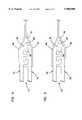
- FIG. 1is a perspective view of a flexible, resealable package, according to an example embodiment of the present invention
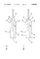
- FIG. 2is a fragmented, cross-sectional, somewhat schematic view of a resealable closure mechanism, according to an example embodiment of the present invention
- FIG. 3is a fragmented, cross-sectional, somewhat schematic view of the resealable closure mechanism of FIG. 2 at the side seal of the package of FIG. 1, also according to an example embodiment of the present invention
- FIG. 4is a fragmented, cross-sectional, somewhat schematic view of a resealable closure mechanism, according to a second example embodiment of the present invention.
- FIG. 5is a fragmented, cross-sectional, somewhat schematic view of a resealable closure mechanism, according to a third example embodiment of the present invention.
- FIG. 6is a fragmented, cross-sectional, somewhat schematic view of a resealable closure mechanism, according to a fourth example embodiment of the present invention.
- FIG. 7is a fragmented, cross-sectional, somewhat schematic view of a resealable closure mechanism, according to a fifth example embodiment of the present invention.
- FIG. 8is a fragmented, cross-sectional, somewhat schematic view of a resealable closure mechanism, according to a sixth example embodiment of the present invention.
- FIG. 9is a fragmented, cross-sectional, somewhat schematic view of a resealable closure mechanism, according to a seventh example embodiment of the present invention.
- the present inventionis believed to be applicable to a variety of packaging arrangements.
- the inventionhas been found to be particularly advantageous for manufacturing resealable closure mechanisms.
- An appreciation of various aspects of the inventionis best gained through a discussion of an application example for such a packaging arrangement.
- FIG. 1illustrates an example type of package 10 that benefits from the use of such resealable closure mechanisms.
- FIG. 1illustrates an example packaging arrangement in the form of a flexible package 10 having a closure mechanism 14 constructed in accordance with the present invention.
- the flexible package 10includes first and second opposed panel sections 16, 18, typically made from a flexible, polymeric film.
- the first and second panel sections 16, 18are heat-sealed together along two edges 20, 22 and meet at a fold line 23 in order to form a three-edged containment section for a product within the interior of the package 10.
- the fold line 23comprises a product supporting bottom or bottom edge 25, depending on the orientation that the package 10 is held.
- two separate panel sections 16, 18 of polymeric filmmay be used and heat-sealed together along the two opposite edges 20, 22 and along the bottom edge 25.
- Accessis provided to the interior 24 of the package 10 through a mouth 26.
- the package 10includes tear strings and/or notches at the mouth 26 to assist with opening the package 10.
- the package 10includes a product side and a consumer side.
- product siderefers to the volume inside of the package 10 between the closure mechanism 14, the two side edges 20, 22, and the bottom edge 25.
- the “consumer side”refers to a side opposite of the product side, and is in the region of the package 10 accessible by the user.
- the flexible package 10may be used to hold a variety of products. Such products may include groceries, edible food products, clothing, liquids, and other articles.
- a resealable closure mechanism 14is illustrated in FIG. 1 at the mouth 26 of the flexible package 10. Each closure mechanism 14 extends the entire width of the package 10.
- the closure mechanism 14can be one of a variety of closure mechanisms.
- the resealable closure mechanism 14 of FIG. 1is shown in the specific form of a dual-track zipper-type mechanism 14.
- dual-trackit is meant that the closure mechanism has two sets of interlocking closure flanges.
- the resealable closure mechanism 14 of FIG. 1is shown in the specific form of a single-track zipper-type mechanism.
- single-trackit is meant that the closure mechanism has a single set of interlocking closure flanges.
- zipper-type mechanismit is meant a structure having oppositely disposed interlocking or mating profiles, which under the application of pressure, will interlock and block access between the profiles.
- the closure mechanism 14is shown in expanded form and includes an elongated male closure profile 40 and an elongated female closure profile 42.
- the closure profiles 40, 42are manufactured separately from each other.
- the male closure profile 40is comprised of a base strip 46, an interlocking closure member 47, two gripping ridges 66, 68, and a sealant layer 55.
- the interlocking closure member 47has two interlocking closure flanges 48, 50 and two guide posts 52, 54.
- the sealant layer 55is attached to the first panel section 16 of the package 10 of FIG. 1.
- the sealant layer 55facilitates bonding between the closure profile 40 and the first panel section 16.
- the base strip 46is attached to the sealant layer 55.
- the interlocking closure flanges 48, 50extend out from the base strip 46 and are generally perpendicular to the base strip 46.
- the guide posts 52, 54also extend out from the base strip 46 and are generally perpendicular to the base strip 46.
- the guide posts 52, 54aid in holding the closure mechanism 14 closed and in aligning the male closure profile 40 with the female closure profile 42.
- the gripping ridges 66, 68extend out from the base strip 46 and aid the consumer in grasping the closure profile 40.
- the male closure profile 40does not have a sealant layer 55.
- the base strip 46is attached directly to the first panel section 16 of the package 10 of FIG. 1.
- the female closure profile 42is likewise comprised of a base strip 56, an interlocking closure member 57, two gripping ridges 70, 72, and a sealant layer 63.
- the interlocking closure member 57has two interlocking closure flanges 58, 60 and a guide post 62.
- the sealant layer 63is attached to the second panel section 18 of the package 10 of FIG. 1.
- the sealant layer 63facilitates bonding between the closure profile 42 and the second panel section 18.
- the base strip 56is attached to the sealant layer 63.
- the interlocking closure flanges 58, 60extend out from the base strip 56 and are generally perpendicular to the base strip 56.
- the guide post 62also extends out from the base strip 56 and is generally perpendicular to the base strip 56.
- the guide post 62aids in holding the closure mechanism 14 closed and in aligning the female closure profile 42 with the male closure profile 40.
- the gripping ridges 70, 72extend out from the base strip 56 and aid the consumer in grasping the closure profile 42.
- the female closure profile 42does not have a sealant layer 63.
- the base strip 56is attached directly to the second panel section 18 of the package 10 of FIG. 1 or directly heat sealed to a bag wall film that has the sealant layer.
- the male and female closure profiles 40, 42are designed to engage with one another to form a resealable closure mechanism 14.
- the interlocking closure flanges 48, 50 of the male closure profile 40 and the interlocking closure flanges 58, 60 of the female closure profile 42extend from the base strips 46, 56, respectively, a sufficient distance to allow mechanical engagement therebetween.
- Pressureis applied to the closure profiles 40, 42 as they engage and form a resealable closure mechanism 14.
- the consumergrasps the male closure profile 40 from the consumer side of the package 10 and pulls it away from the female closure profile 42, causing the two closure profiles 40, 42 to disengage.
- the gripping ridges 66, 68 of the male closure profile 40 and the gripping ridges 70, 72 of the female closure profile 42provide the consumer with a place to grasp the closure profiles 40, 42 to pull them apart.
- the closure profiles 40, 42are also sealed together at side edges 20, 22 of FIG. 1 to further aid in aligning the closure profiles 40, 42.
- the closure profiles 40, 42are formed by two separate extrusions or through two separate openings of the common extrusion.
- the resealable closure mechanism 14is made of a flexible polymeric material, such as polyethylene or polypropylene.
- the closure arrangement illustrated in FIG. 2is manufactured using conventional extrusion and heat sealing techniques.
- the closure profiles 40, 42are extruded through a die plate fed by a plurality of extruders. These extruders carry the different molten materials for forming the closure profiles 40, 42.
- the die plateincludes input ports, output ports, and channels connecting these input ports to output ports.
- the extrudersfeed the different molten materials to different input ports, and the channels are designed to configure the molten materials into the shape of the closure profiles 40, 42.
- the sealant layers 55, 63are coextruded with the closure profiles 40, 42, such that the sealant layers 55, 63 are bonded to the base strips 46, 56, respectively, of the male and female closure profiles 40, 42, respectively.
- FIG. 3is a cross-sectional view of the package 10 of FIG. 1 taken along one of the side seal edges 20.
- the closure profiles 40, 42 of FIG. 2are shown in their interlocked position. In this embodiment, the closure profiles 40, 42 do not have sealant layers and are bonded directly to package films 16, 18, respectively.
- the interlocking closure flanges 58, 60 of the female closure profile 42have mechanically engaged with the interlocking closure flanges 48, 50 of the male closure profile 40.
- the package 10is hermetically sealed along the side edge 20. The sealing process incompletely seals the side edge 20.
- the sealing processleaves a gap, or transition triangle, either on the product side or the consumer side of the closure mechanism 14.
- the gapis on the product side of the closure mechanism 14 and is represented as region 78.
- the region 78generally has a triangular cross-section and has two legs 80, 82.
- the legs 80, 82define an angle A with respect to the base strips 46, 56, respectively.
- the large area of the region 78allows materials to pass through the side edge 20.
- the closure profiles 40, 42are designed to reduce the area of the region 78, and thereby further seal the side edge 20 of package 10 of FIG. 1.
- the guide post 54 of the male closure profile 40 and the interlocking closure flange 60 of the female closure profile 42are bent at points 84, 86, respectively.
- the angle of the bends 84, 86is approximately equal to angle A of the triangular region 78.
- the bending of the guide post 54 and the interlocking closure flange 60allows the side edges 20, 22 to be sealed closer to the closure mechanism 14, thus reducing the area of the region 78.
- the closure profiles 140, 142have structure analogous to the closure profiles 40, 42, respectively, of FIG. 2.
- the guide post 154 of the male closure profile 140is bent at 184.
- the interlocking closure flange 160 of the female closure profile 142is bent at 186.
- the bending of the guide post 154 and the interlocking closure flange 160allows the side edges 20, 22 of the package 10 of FIG. 1 to be sealed closer to the closure mechanism 114.
- a protrusion or horizontal rib 190is coextruded with the male closure profile 140.
- the horizontal rib 190extends outwardly from the guide post 154 and is generally perpendicular to the guide post 154.
- the horizontal rib 190further reduces the area of the triangular region 178.
- the horizontal rib 190is shaped as a rib or knob.
- the horizontal rib 190could be one of a variety of shapes designed to take up space and reduce the area of the region 178.
- the closure profiles 240, 242have structure analogous to the closure profiles 140, 142, respectively, of FIG. 4.
- the guide post 254 of the male closure profile 240is bent at 284.
- the interlocking closure flange 260 of the female closure profile 242is bent at 286.
- a protrusion or horizontal rib 290is coextruded with the male closure profile 240.
- the horizontal rib 290extends outwardly from the guide post 254.
- the horizontal rib 290further reduces the area of the triangular region 278.
- the horizontal rib 290is triangularly shaped congruous to the triangular region 278.
- the triangular shape of the horizontal rib 290allows the size of the horizontal rib 290 to be greater, while still fitting within the triangular region 278, thus further reducing the area of the region 278.
- the closure profiles 340, 342have structure analogous to the closure profiles 40, 42 of FIG. 3.
- the guide post 354 of the male closure profile 340is bent at 384.
- the interlocking closure flange 360 of the female closure profile 342is bent at 386.
- a protrusion or finger 390is coextruded with the male closure profile 340.
- the finger 390extends outwardly from the guide post 354 at the same angle as the angle at 384. This angle is approximately the same as angle A of the triangular region 78 of FIG. 3. The finger 390 further reduces the area of the region 378.
- the closure profiles 440, 442have structure analogous to the closure profiles 40, 42, respectively, of FIG. 3.
- the base strip 446 of the male closure profile 440has an extension 491 that is bent at 484.
- the base strip 456 of the female closure profile 442has an extension 492 that is bent at 486.
- the angle of these bends 484, 486is approximately the same as angle A of the triangular region 78 of FIG. 3.
- the base extensions 491, 492are coextruded with the closure profiles 440, 442, respectively.
- the base extensions 491, 492extend into the transition triangle 478, reducing the area of the region 478.
- the closure profiles 540, 542have structure analogous to the closure profiles 40, 42, respectively, of FIG. 3.
- the sealant layer 555 of the male closure profile 540is extended into the triangular region 578 and is bent at 584.
- the sealant layer 563 of the female closure profile 542is extended into the region 578 and is bent at 586.
- the angle of these bends 584, 586is approximately the same as angle A of the triangular region 78 of FIG. 3.
- the sealant layers 555, 563are coextruded with the closure profiles 540, 542. The extension of the sealant layers 555, 563 into the region 578 reduces the area of the region 578.
- the male closure profile 640is comprised of a base strip 646 and an interlocking closure member 647.
- the interlocking closure member 647has an interlocking closure flange 648.
- the base strip 646is attached to the first package film 16 of package 10 of FIG. 1.
- the male closure profile 640also includes a ridge 650.
- the ridge 650extends out from the base strip 646.
- the shape and size of ridge 650are designed to reduce the area of the triangular region 678.
- the ridge 650is coextruded with the male closure profile 640.
- the female closure profile 642is comprised of a base strip 656 and an interlocking closure member 657.
- the interlocking closure member 657has two interlocking closure flanges 658, 660.
- the base strip 656is attached to the second package film 18 of package 10 of FIG. 1.
- the male and female closure profiles 640, 642are designed to engage with one another to form a resealable closure mechanism 614.
- the interlocking closure flange 648 of the male closure profile 640 and the interlocking closure flanges 658, 660 of the female closure profile 642extend from the base strips 646, 656, respectively, a sufficient distance to allow mechanical engagement therebetween.
- Pressureis applied to the closure profiles 640, 642 as they engage and form a resealable closure mechanism 614.
- the consumergrasps the male closure profile 640 from the consumer side of the package 10 and pulls it away from the female closure profile 642, causing the two closure profiles 640, 642 to disengage.
- Closure profiles 640, 642are also sealed together at edges 20, 22 of FIG. 1 to further aid an aligning of the closure profiles 640, 642.
Landscapes
- Engineering & Computer Science (AREA)
- Mechanical Engineering (AREA)
- Packages (AREA)
Abstract
Description
Claims (14)
Priority Applications (1)
| Application Number | Priority Date | Filing Date | Title |
|---|---|---|---|
| US09/083,554US5988880A (en) | 1998-05-22 | 1998-05-22 | Resealable closure mechanism |
Applications Claiming Priority (1)
| Application Number | Priority Date | Filing Date | Title |
|---|---|---|---|
| US09/083,554US5988880A (en) | 1998-05-22 | 1998-05-22 | Resealable closure mechanism |
Publications (1)
| Publication Number | Publication Date |
|---|---|
| US5988880Atrue US5988880A (en) | 1999-11-23 |
Family
ID=22179085
Family Applications (1)
| Application Number | Title | Priority Date | Filing Date |
|---|---|---|---|
| US09/083,554Expired - Fee RelatedUS5988880A (en) | 1998-05-22 | 1998-05-22 | Resealable closure mechanism |
Country Status (1)
| Country | Link |
|---|---|
| US (1) | US5988880A (en) |
Cited By (27)
| Publication number | Priority date | Publication date | Assignee | Title |
|---|---|---|---|---|
| US6511406B1 (en)* | 1999-05-27 | 2003-01-28 | Aru Corporation | Method and apparatus for producing a compression preservation bag |
| US6582122B2 (en)* | 2000-04-10 | 2003-06-24 | Kabushiki Kaisha Aichi Shokai | Chuck and plastic packaging bag with chuck |
| US20030236158A1 (en)* | 2002-06-24 | 2003-12-25 | Pawloski James C. | Method of and apparatus for producing a reclosable pouch |
| US20040086206A1 (en)* | 2002-10-30 | 2004-05-06 | Mladomir Tomic | Leak-proof package design including reclosable zipper having slider including a full-length plow |
| US20040136617A1 (en)* | 2003-01-02 | 2004-07-15 | Gerrits Robert P. | Liquid tight locking arrangement with sealing fingers |
| US20060124490A1 (en)* | 2004-12-10 | 2006-06-15 | Saint-Gobain Technical Fabrics Canada, Ltd | Packaged roll of textile fabric and method of packaging same |
| US7137736B2 (en) | 2003-05-19 | 2006-11-21 | S.C. Johnson Home Storage, Inc. | Closure device for a reclosable pouch |
| US7419300B2 (en) | 2004-06-16 | 2008-09-02 | S.C. Johnson Home Storage, Inc. | Pouch having fold-up handles |
| US7494333B2 (en) | 2004-06-04 | 2009-02-24 | S.C. Johnson Home Storage, Inc. | Apparatus for forming multiple closure elements |
| US7784160B2 (en) | 2007-03-16 | 2010-08-31 | S.C. Johnson & Son, Inc. | Pouch and airtight resealable closure mechanism therefor |
| US7850368B2 (en) | 2004-06-04 | 2010-12-14 | S.C. Johnson & Son, Inc. | Closure device for a reclosable pouch |
| US7857515B2 (en) | 2007-06-15 | 2010-12-28 | S.C. Johnson Home Storage, Inc. | Airtight closure mechanism for a reclosable pouch |
| US7874731B2 (en) | 2007-06-15 | 2011-01-25 | S.C. Johnson Home Storage, Inc. | Valve for a recloseable container |
| US7887238B2 (en) | 2007-06-15 | 2011-02-15 | S.C. Johnson Home Storage, Inc. | Flow channels for a pouch |
| US7886412B2 (en) | 2007-03-16 | 2011-02-15 | S.C. Johnson Home Storage, Inc. | Pouch and airtight resealable closure mechanism therefor |
| US7946766B2 (en) | 2007-06-15 | 2011-05-24 | S.C. Johnson & Son, Inc. | Offset closure mechanism for a reclosable pouch |
| US7967509B2 (en) | 2007-06-15 | 2011-06-28 | S.C. Johnson & Son, Inc. | Pouch with a valve |
| US8469593B2 (en) | 2011-02-22 | 2013-06-25 | S.C. Johnson & Son, Inc. | Reclosable bag having a press-to-vent zipper |
| US8550716B2 (en) | 2010-06-22 | 2013-10-08 | S.C. Johnson & Son, Inc. | Tactile enhancement mechanism for a closure mechanism |
| US8568031B2 (en) | 2011-02-22 | 2013-10-29 | S.C. Johnson & Son, Inc. | Clicking closure device for a reclosable pouch |
| US20130299512A1 (en)* | 2012-05-14 | 2013-11-14 | Naira Gevorkian | Collapsible dispensing tube with internal press-to-close sealers to prevent reverse flow of the content towards the closed end |
| US8974118B2 (en) | 2010-10-29 | 2015-03-10 | S.C. Johnson & Son, Inc. | Reclosable bag having a sound producing zipper |
| US20150113833A1 (en)* | 2013-10-31 | 2015-04-30 | Back Beat, Inc. | Removable accessories for footwear and footwear with removable accessories |
| US9327875B2 (en) | 2010-10-29 | 2016-05-03 | S.C. Johnson & Son, Inc. | Reclosable bag having a loud sound during closing |
| US11180286B2 (en) | 2010-10-29 | 2021-11-23 | S. C. Johnson & Son, Inc. | Reclosable bag having a loud sound during closing |
| USD992411S1 (en)* | 2021-05-13 | 2023-07-18 | Xiaoqun GU | Packaging bag |
| US12409978B2 (en) | 2023-04-13 | 2025-09-09 | S. C. Johnson & Son, Inc. | Closure system for pouch or container |
Citations (20)
| Publication number | Priority date | Publication date | Assignee | Title |
|---|---|---|---|---|
| US2144755A (en)* | 1937-01-11 | 1939-01-24 | Eugene L Alexander | Closure device |
| US3986914A (en)* | 1972-02-11 | 1976-10-19 | Uly-Pak, Inc. | Heat-sealing method for plastic containers |
| US4561108A (en)* | 1983-12-30 | 1985-12-24 | Union Carbide Corporation | Interlocking closure bag for use in high temperature environment |
| US4658433A (en)* | 1985-09-11 | 1987-04-14 | First Brands Corporation | Rib and groove closure bag with bead sealed sides |
| US4736496A (en)* | 1982-12-27 | 1988-04-12 | The Dow Chemical Company | Closure for thermoplastic containers |
| US4756629A (en)* | 1987-04-23 | 1988-07-12 | Minigrip, Inc. | System for producing non-compatible zipper film |
| US4832505A (en)* | 1988-03-11 | 1989-05-23 | Minigrip, Inc. | Tamper evident link bags |
| US4854017A (en)* | 1986-07-22 | 1989-08-08 | First Brands Corporation | Multiposition interlocking closure fastening device |
| US4890935A (en)* | 1988-08-16 | 1990-01-02 | Minigrip, Inc. | Leak resistant zipper |
| US4907321A (en)* | 1987-06-22 | 1990-03-13 | First Brands Corporation | Enhanced color change interlocking closure strip |
| US4949527A (en)* | 1988-06-29 | 1990-08-21 | Zip-Pak Incorporated | Method of forming a reclosable tray |
| US5012561A (en)* | 1990-05-18 | 1991-05-07 | The Dow Chemical Company | Closure for reclosable thermoplastic containers |
| US5118202A (en)* | 1989-03-02 | 1992-06-02 | Bruno Edward C | Tamper proof, recloseable plastic bag containing an object and method of making the same |
| US5209574A (en)* | 1991-11-22 | 1993-05-11 | Minigrip, Inc. | Reclosable plastic bag with sliderless zipper |
| US5351369A (en)* | 1992-06-16 | 1994-10-04 | Illinois Tool Works, Inc. | Moisture-resistant fastener |
| US5369847A (en)* | 1992-03-25 | 1994-12-06 | Yoshida Kogyo K.K. | Flexible fastener |
| US5372428A (en)* | 1994-04-04 | 1994-12-13 | Bruno; Edward C. | Tamper evident bag with perforations on the sides and on the flanges |
| US5558439A (en)* | 1995-06-08 | 1996-09-24 | Minigrip Inc. | Wedge zipper |
| US5577305A (en)* | 1995-05-08 | 1996-11-26 | Johnson; James R. | Fastener assembly |
| US5810478A (en)* | 1997-02-26 | 1998-09-22 | Custom Packaging Systems, Inc. | Bulk bag with lift straps and exterior liner |
- 1998
- 1998-05-22USUS09/083,554patent/US5988880A/ennot_activeExpired - Fee Related
Patent Citations (20)
| Publication number | Priority date | Publication date | Assignee | Title |
|---|---|---|---|---|
| US2144755A (en)* | 1937-01-11 | 1939-01-24 | Eugene L Alexander | Closure device |
| US3986914A (en)* | 1972-02-11 | 1976-10-19 | Uly-Pak, Inc. | Heat-sealing method for plastic containers |
| US4736496A (en)* | 1982-12-27 | 1988-04-12 | The Dow Chemical Company | Closure for thermoplastic containers |
| US4561108A (en)* | 1983-12-30 | 1985-12-24 | Union Carbide Corporation | Interlocking closure bag for use in high temperature environment |
| US4658433A (en)* | 1985-09-11 | 1987-04-14 | First Brands Corporation | Rib and groove closure bag with bead sealed sides |
| US4854017A (en)* | 1986-07-22 | 1989-08-08 | First Brands Corporation | Multiposition interlocking closure fastening device |
| US4756629A (en)* | 1987-04-23 | 1988-07-12 | Minigrip, Inc. | System for producing non-compatible zipper film |
| US4907321A (en)* | 1987-06-22 | 1990-03-13 | First Brands Corporation | Enhanced color change interlocking closure strip |
| US4832505A (en)* | 1988-03-11 | 1989-05-23 | Minigrip, Inc. | Tamper evident link bags |
| US4949527A (en)* | 1988-06-29 | 1990-08-21 | Zip-Pak Incorporated | Method of forming a reclosable tray |
| US4890935A (en)* | 1988-08-16 | 1990-01-02 | Minigrip, Inc. | Leak resistant zipper |
| US5118202A (en)* | 1989-03-02 | 1992-06-02 | Bruno Edward C | Tamper proof, recloseable plastic bag containing an object and method of making the same |
| US5012561A (en)* | 1990-05-18 | 1991-05-07 | The Dow Chemical Company | Closure for reclosable thermoplastic containers |
| US5209574A (en)* | 1991-11-22 | 1993-05-11 | Minigrip, Inc. | Reclosable plastic bag with sliderless zipper |
| US5369847A (en)* | 1992-03-25 | 1994-12-06 | Yoshida Kogyo K.K. | Flexible fastener |
| US5351369A (en)* | 1992-06-16 | 1994-10-04 | Illinois Tool Works, Inc. | Moisture-resistant fastener |
| US5372428A (en)* | 1994-04-04 | 1994-12-13 | Bruno; Edward C. | Tamper evident bag with perforations on the sides and on the flanges |
| US5577305A (en)* | 1995-05-08 | 1996-11-26 | Johnson; James R. | Fastener assembly |
| US5558439A (en)* | 1995-06-08 | 1996-09-24 | Minigrip Inc. | Wedge zipper |
| US5810478A (en)* | 1997-02-26 | 1998-09-22 | Custom Packaging Systems, Inc. | Bulk bag with lift straps and exterior liner |
Cited By (42)
| Publication number | Priority date | Publication date | Assignee | Title |
|---|---|---|---|---|
| US6511406B1 (en)* | 1999-05-27 | 2003-01-28 | Aru Corporation | Method and apparatus for producing a compression preservation bag |
| US6582122B2 (en)* | 2000-04-10 | 2003-06-24 | Kabushiki Kaisha Aichi Shokai | Chuck and plastic packaging bag with chuck |
| US20030236158A1 (en)* | 2002-06-24 | 2003-12-25 | Pawloski James C. | Method of and apparatus for producing a reclosable pouch |
| US20040086206A1 (en)* | 2002-10-30 | 2004-05-06 | Mladomir Tomic | Leak-proof package design including reclosable zipper having slider including a full-length plow |
| US6817763B2 (en)* | 2002-10-30 | 2004-11-16 | Reynolds Consumer Products, Inc. | Leak-proof package design including reclosable zipper having slider including a full-length plow |
| US20040136617A1 (en)* | 2003-01-02 | 2004-07-15 | Gerrits Robert P. | Liquid tight locking arrangement with sealing fingers |
| US7189001B2 (en) | 2003-01-02 | 2007-03-13 | Reynolds Consumer Products, Inc. | Liquid tight locking arrangement with sealing fingers |
| US7410298B2 (en) | 2003-05-19 | 2008-08-12 | S.C. Johnson Home Storage, Inc. | Closure device for a reclosable pouch |
| US7137736B2 (en) | 2003-05-19 | 2006-11-21 | S.C. Johnson Home Storage, Inc. | Closure device for a reclosable pouch |
| US7850368B2 (en) | 2004-06-04 | 2010-12-14 | S.C. Johnson & Son, Inc. | Closure device for a reclosable pouch |
| US7494333B2 (en) | 2004-06-04 | 2009-02-24 | S.C. Johnson Home Storage, Inc. | Apparatus for forming multiple closure elements |
| US7419300B2 (en) | 2004-06-16 | 2008-09-02 | S.C. Johnson Home Storage, Inc. | Pouch having fold-up handles |
| US7168561B2 (en)* | 2004-12-10 | 2007-01-30 | Saint-Gobain Technical Fabrics Canada, Ltd. | Packaged roll of textile fabric and method of packaging same |
| WO2006063097A3 (en)* | 2004-12-10 | 2007-01-04 | Saint Gobain Technical Fabrics | Packaged roll of textile fabric and method of packaging same |
| US20060124490A1 (en)* | 2004-12-10 | 2006-06-15 | Saint-Gobain Technical Fabrics Canada, Ltd | Packaged roll of textile fabric and method of packaging same |
| US7886412B2 (en) | 2007-03-16 | 2011-02-15 | S.C. Johnson Home Storage, Inc. | Pouch and airtight resealable closure mechanism therefor |
| US7784160B2 (en) | 2007-03-16 | 2010-08-31 | S.C. Johnson & Son, Inc. | Pouch and airtight resealable closure mechanism therefor |
| US8827556B2 (en) | 2007-03-16 | 2014-09-09 | S.C. Johnson & Son, Inc. | Pouch and airtight resealable closure mechanism therefor |
| US8176604B2 (en) | 2007-03-16 | 2012-05-15 | S.C. Johnson & Son, Inc. | Pouch and airtight resealable closure mechanism therefor |
| US7946766B2 (en) | 2007-06-15 | 2011-05-24 | S.C. Johnson & Son, Inc. | Offset closure mechanism for a reclosable pouch |
| US7967509B2 (en) | 2007-06-15 | 2011-06-28 | S.C. Johnson & Son, Inc. | Pouch with a valve |
| US7874731B2 (en) | 2007-06-15 | 2011-01-25 | S.C. Johnson Home Storage, Inc. | Valve for a recloseable container |
| US8231273B2 (en) | 2007-06-15 | 2012-07-31 | S.C. Johnson & Son, Inc. | Flow channel profile and a complementary groove for a pouch |
| US7857515B2 (en) | 2007-06-15 | 2010-12-28 | S.C. Johnson Home Storage, Inc. | Airtight closure mechanism for a reclosable pouch |
| US7887238B2 (en) | 2007-06-15 | 2011-02-15 | S.C. Johnson Home Storage, Inc. | Flow channels for a pouch |
| US8550716B2 (en) | 2010-06-22 | 2013-10-08 | S.C. Johnson & Son, Inc. | Tactile enhancement mechanism for a closure mechanism |
| US9327875B2 (en) | 2010-10-29 | 2016-05-03 | S.C. Johnson & Son, Inc. | Reclosable bag having a loud sound during closing |
| US12275561B2 (en) | 2010-10-29 | 2025-04-15 | S. C. Johnson & Son, Inc. | Reclosable bag having a loud sound during closing |
| US11691789B2 (en) | 2010-10-29 | 2023-07-04 | S. C. Johnson & Son, Inc. | Reclosable bag having a loud sound during closing |
| US11180286B2 (en) | 2010-10-29 | 2021-11-23 | S. C. Johnson & Son, Inc. | Reclosable bag having a loud sound during closing |
| US8974118B2 (en) | 2010-10-29 | 2015-03-10 | S.C. Johnson & Son, Inc. | Reclosable bag having a sound producing zipper |
| US9914563B2 (en) | 2010-10-29 | 2018-03-13 | S. C. Johnson & Son, Inc. | Reclosable bag having a loud sound during closing |
| US10011396B2 (en) | 2011-02-22 | 2018-07-03 | S. C. Johnson & Son, Inc. | Reclosable pouch having a clicking closure device |
| US9475616B2 (en) | 2011-02-22 | 2016-10-25 | S.C. Johnson & Son, Inc. | Reclosable pouch having a clicking closure device |
| US9126735B2 (en) | 2011-02-22 | 2015-09-08 | S.C. Johnson & Son, Inc. | Reclosable pouch having a clicking closure device |
| US10618697B2 (en) | 2011-02-22 | 2020-04-14 | S. C. Johnson & Son, Inc. | Reclosable pouch having a clicking closure device |
| US8568031B2 (en) | 2011-02-22 | 2013-10-29 | S.C. Johnson & Son, Inc. | Clicking closure device for a reclosable pouch |
| US8469593B2 (en) | 2011-02-22 | 2013-06-25 | S.C. Johnson & Son, Inc. | Reclosable bag having a press-to-vent zipper |
| US20130299512A1 (en)* | 2012-05-14 | 2013-11-14 | Naira Gevorkian | Collapsible dispensing tube with internal press-to-close sealers to prevent reverse flow of the content towards the closed end |
| US20150113833A1 (en)* | 2013-10-31 | 2015-04-30 | Back Beat, Inc. | Removable accessories for footwear and footwear with removable accessories |
| USD992411S1 (en)* | 2021-05-13 | 2023-07-18 | Xiaoqun GU | Packaging bag |
| US12409978B2 (en) | 2023-04-13 | 2025-09-09 | S. C. Johnson & Son, Inc. | Closure system for pouch or container |
Similar Documents
| Publication | Publication Date | Title |
|---|---|---|
| US5988880A (en) | Resealable closure mechanism | |
| US5983466A (en) | Leakproof resealable slider closure mechanism | |
| US5947603A (en) | Resealable closure mechanism having a slider device and separate housing | |
| US6533456B1 (en) | Reclosable stand-up package, and methods | |
| US6231236B1 (en) | Resealable package having venting structure and methods | |
| US5718024A (en) | Closure arrangement with tapered flange | |
| US6461042B1 (en) | Resealable closure mechanism having a slider device | |
| EP1375369B1 (en) | Closure for a package | |
| US6164826A (en) | Resealable spout for side-gusseted packages | |
| US5238306A (en) | Method of producing a sealing system for a reclosable webbed-wall package, and system made | |
| US4848928A (en) | Package with reclosable fin and method | |
| US6217215B1 (en) | Closure mechanism having a perceptible feedback system | |
| US4787754A (en) | Reclosable flexible bags having fastener profiles attached to exterior walls thereof and a method of making same | |
| US8827556B2 (en) | Pouch and airtight resealable closure mechanism therefor | |
| EP0982117B1 (en) | Intermediate Layer for Fastener Tape | |
| CA2308729C (en) | Adhesively secured snap closure for flexible packages and flexible packages including the same | |
| EP1020369B1 (en) | Resealable flexible package | |
| EP0945359A2 (en) | Zip lock bag closure with pealable seal | |
| US6402375B1 (en) | Resealable closure mechanism having a slider device | |
| EP1366999A1 (en) | Reclosable packaging | |
| US6092931A (en) | Closure mechanism with a heat-insulating layer | |
| EP1590253B1 (en) | Recloseable bag | |
| US6063224A (en) | Method for separate closure extrusion | |
| US6247844B1 (en) | Resealable slider closure mechanism with separate plow | |
| EP0956241B1 (en) | Multicompartment thermoplastic bag |
Legal Events
| Date | Code | Title | Description |
|---|---|---|---|
| AS | Assignment | Owner name:REYNOLDS CONSUMER PRODUCTS, INC., VIRGINIA Free format text:ASSIGNMENT OF ASSIGNORS INTEREST;ASSIGNOR:TOMIC, MLADOMIR;REEL/FRAME:009199/0041 Effective date:19980518 | |
| FPAY | Fee payment | Year of fee payment:4 | |
| FPAY | Fee payment | Year of fee payment:8 | |
| FEPP | Fee payment procedure | Free format text:PAYOR NUMBER ASSIGNED (ORIGINAL EVENT CODE: ASPN); ENTITY STATUS OF PATENT OWNER: LARGE ENTITY | |
| AS | Assignment | Owner name:CREDIT SUISSE, SYDNEY BRANCH, AUSTRALIA Free format text:NOTICE AND CONFIRMATION OF GRANT OF SECURITY INTEREST IN PATENTS;ASSIGNOR:REYNOLDS CONSUMER PRODUCTS, INC.;REEL/FRAME:020828/0496 Effective date:20080229 Owner name:CREDIT SUISSE, SYDNEY BRANCH,AUSTRALIA Free format text:NOTICE AND CONFIRMATION OF GRANT OF SECURITY INTEREST IN PATENTS;ASSIGNOR:REYNOLDS CONSUMER PRODUCTS, INC.;REEL/FRAME:020828/0496 Effective date:20080229 | |
| AS | Assignment | Owner name:REYNOLDS CONSUMER PRODUCTS, INC., VIRGINIA Free format text:TERMINATION AND RELEASE OF SECURITY INTEREST;ASSIGNOR:CREDIT SUISSE, SYDNEY BRANCH;REEL/FRAME:023546/0309 Effective date:20091105 Owner name:REYNOLDS CONSUMER PRODUCTS, INC.,VIRGINIA Free format text:TERMINATION AND RELEASE OF SECURITY INTEREST;ASSIGNOR:CREDIT SUISSE, SYDNEY BRANCH;REEL/FRAME:023546/0309 Effective date:20091105 | |
| AS | Assignment | Owner name:THE BANK OF NEW YORK MELLON, NEW YORK Free format text:SECURITY AGREEMENT;ASSIGNORS:CLOSURE SYSTEMS INTERNATIONAL INC.;REYNOLDS CONSUMER PRODUCTS INC.;REYNOLDS FOIL INC.;AND OTHERS;REEL/FRAME:023574/0312 Effective date:20091105 Owner name:THE BANK OF NEW YORK MELLON,NEW YORK Free format text:SECURITY AGREEMENT;ASSIGNORS:CLOSURE SYSTEMS INTERNATIONAL INC.;REYNOLDS CONSUMER PRODUCTS INC.;REYNOLDS FOIL INC.;AND OTHERS;REEL/FRAME:023574/0312 Effective date:20091105 | |
| REMI | Maintenance fee reminder mailed | ||
| LAPS | Lapse for failure to pay maintenance fees | ||
| STCH | Information on status: patent discontinuation | Free format text:PATENT EXPIRED DUE TO NONPAYMENT OF MAINTENANCE FEES UNDER 37 CFR 1.362 | |
| FP | Lapsed due to failure to pay maintenance fee | Effective date:20111123 | |
| AS | Assignment | Owner name:REYNOLDS PRESTO PRODUCTS INC., VIRGINIA Free format text:CHANGE OF NAME;ASSIGNOR:REYNOLDS CONSUMER PRODUCTS, INC.;REEL/FRAME:027742/0980 Effective date:20111220 | |
| AS | Assignment | Owner name:REYNOLDS CONSUMER PRODUCTS LLC (F/K/A REYNOLDS FOIL INC.), ILLINOIS Free format text:RELEASE OF SECURITY INTEREST IN CERTAIN PATENT COLLATERAL;ASSIGNOR:THE BANK OF NEW YORK MELLON, AS COLLATERAL AGENT;REEL/FRAME:051798/0051 Effective date:20200204 Owner name:REYNOLDS PRESTO PRODUCTS INC. (F/K/A REYNOLDS CONSUMER PRODUCTS, INC.), ILLINOIS Free format text:RELEASE OF SECURITY INTEREST IN CERTAIN PATENT COLLATERAL;ASSIGNOR:THE BANK OF NEW YORK MELLON, AS COLLATERAL AGENT;REEL/FRAME:051798/0051 Effective date:20200204 |