US5988862A - Integrated system for quickly and accurately imaging and modeling three dimensional objects - Google Patents
Integrated system for quickly and accurately imaging and modeling three dimensional objectsDownload PDFInfo
- Publication number
- US5988862A US5988862AUS08/638,961US63896196AUS5988862AUS 5988862 AUS5988862 AUS 5988862AUS 63896196 AUS63896196 AUS 63896196AUS 5988862 AUS5988862 AUS 5988862A
- Authority
- US
- United States
- Prior art keywords
- scan
- region
- points
- scanning
- user
- Prior art date
- Legal status (The legal status is an assumption and is not a legal conclusion. Google has not performed a legal analysis and makes no representation as to the accuracy of the status listed.)
- Expired - Lifetime
Links
- 238000003384imaging methodMethods0.000titleclaimsdescription12
- 238000011960computer-aided designMethods0.000claimsabstractdescription34
- 238000000034methodMethods0.000claimsdescription66
- 230000006870functionEffects0.000claimsdescription30
- 238000000926separation methodMethods0.000claimsdescription2
- 239000002131composite materialSubstances0.000claims2
- GNFTZDOKVXKIBK-UHFFFAOYSA-N3-(2-methoxyethoxy)benzohydrazideChemical compoundCOCCOC1=CC=CC(C(=O)NN)=C1GNFTZDOKVXKIBK-UHFFFAOYSA-N0.000claims1
- 239000000470constituentSubstances0.000abstractdescription2
- 230000003287optical effectEffects0.000description39
- 230000000007visual effectEffects0.000description30
- 238000005259measurementMethods0.000description27
- 230000008569processEffects0.000description24
- 230000008685targetingEffects0.000description20
- 238000010586diagramMethods0.000description17
- 230000002452interceptive effectEffects0.000description15
- 230000003993interactionEffects0.000description11
- 230000008676importEffects0.000description10
- 230000011218segmentationEffects0.000description10
- 238000012937correctionMethods0.000description9
- 239000000835fiberSubstances0.000description9
- 238000004364calculation methodMethods0.000description8
- 239000013078crystalSubstances0.000description8
- 230000010354integrationEffects0.000description8
- 230000007246mechanismEffects0.000description8
- 238000012800visualizationMethods0.000description8
- 238000006243chemical reactionMethods0.000description7
- 238000010276constructionMethods0.000description7
- 230000008859changeEffects0.000description6
- 238000013461designMethods0.000description6
- 238000010304firingMethods0.000description6
- 238000011160researchMethods0.000description6
- 230000004044responseEffects0.000description6
- 230000009977dual effectEffects0.000description5
- 230000000694effectsEffects0.000description5
- 230000033001locomotionEffects0.000description5
- 238000012423maintenanceMethods0.000description5
- 230000008447perceptionEffects0.000description5
- 230000006835compressionEffects0.000description4
- 238000007906compressionMethods0.000description4
- 238000005520cutting processMethods0.000description4
- 238000012217deletionMethods0.000description4
- 230000037430deletionEffects0.000description4
- 238000012545processingMethods0.000description4
- 238000012935AveragingMethods0.000description3
- 241001057362CyraSpecies0.000description3
- 230000005540biological transmissionEffects0.000description3
- 238000004422calculation algorithmMethods0.000description3
- 238000004891communicationMethods0.000description3
- 238000005516engineering processMethods0.000description3
- 238000009499grossingMethods0.000description3
- 238000007726management methodMethods0.000description3
- 238000004519manufacturing processMethods0.000description3
- 238000001208nuclear magnetic resonance pulse sequenceMethods0.000description3
- 238000002310reflectometryMethods0.000description3
- 238000009877renderingMethods0.000description3
- 230000009466transformationEffects0.000description3
- 230000009471actionEffects0.000description2
- 230000003466anti-cipated effectEffects0.000description2
- 230000003667anti-reflective effectEffects0.000description2
- 230000008901benefitEffects0.000description2
- 230000002457bidirectional effectEffects0.000description2
- 238000000576coating methodMethods0.000description2
- 230000001427coherent effectEffects0.000description2
- 238000005094computer simulationMethods0.000description2
- 230000003750conditioning effectEffects0.000description2
- 230000001419dependent effectEffects0.000description2
- 238000009826distributionMethods0.000description2
- 230000007613environmental effectEffects0.000description2
- 238000007667floatingMethods0.000description2
- 238000003780insertionMethods0.000description2
- 230000037431insertionEffects0.000description2
- 230000002045lasting effectEffects0.000description2
- 238000013507mappingMethods0.000description2
- 239000000463materialSubstances0.000description2
- 238000005457optimizationMethods0.000description2
- 230000036961partial effectEffects0.000description2
- 238000002360preparation methodMethods0.000description2
- 230000009467reductionEffects0.000description2
- 230000002829reductive effectEffects0.000description2
- 239000007787solidSubstances0.000description2
- 230000003068static effectEffects0.000description2
- 239000000126substanceSubstances0.000description2
- 238000012360testing methodMethods0.000description2
- 238000009966trimmingMethods0.000description2
- 229910001369BrassInorganic materials0.000description1
- XUIMIQQOPSSXEZ-UHFFFAOYSA-NSiliconChemical compound[Si]XUIMIQQOPSSXEZ-UHFFFAOYSA-N0.000description1
- 229910000831SteelInorganic materials0.000description1
- 230000001133accelerationEffects0.000description1
- 230000004913activationEffects0.000description1
- 238000004458analytical methodMethods0.000description1
- 238000013459approachMethods0.000description1
- 230000003190augmentative effectEffects0.000description1
- 230000006399behaviorEffects0.000description1
- 230000003542behavioural effectEffects0.000description1
- 239000010951brassSubstances0.000description1
- 239000011248coating agentSubstances0.000description1
- 230000008878couplingEffects0.000description1
- 238000010168coupling processMethods0.000description1
- 238000005859coupling reactionMethods0.000description1
- 238000013523data managementMethods0.000description1
- 238000013500data storageMethods0.000description1
- 230000007423decreaseEffects0.000description1
- 230000003247decreasing effectEffects0.000description1
- 230000001934delayEffects0.000description1
- 238000011161developmentMethods0.000description1
- 230000018109developmental processEffects0.000description1
- 239000006185dispersionSubstances0.000description1
- 238000006073displacement reactionMethods0.000description1
- 238000009429electrical wiringMethods0.000description1
- 230000002708enhancing effectEffects0.000description1
- JEIPFZHSYJVQDO-UHFFFAOYSA-Nferric oxideChemical compoundO=[Fe]O[Fe]=OJEIPFZHSYJVQDO-UHFFFAOYSA-N0.000description1
- 239000003365glass fiberSubstances0.000description1
- 238000005286illuminationMethods0.000description1
- 230000006872improvementEffects0.000description1
- 238000005304joiningMethods0.000description1
- 230000000670limiting effectEffects0.000description1
- 230000007774longtermEffects0.000description1
- 239000011159matrix materialSubstances0.000description1
- 238000010297mechanical methods and processMethods0.000description1
- 239000002184metalSubstances0.000description1
- 238000012986modificationMethods0.000description1
- 230000004048modificationEffects0.000description1
- 230000006855networkingEffects0.000description1
- 230000010287polarizationEffects0.000description1
- 230000002028prematureEffects0.000description1
- 238000003825pressingMethods0.000description1
- 238000001454recorded imageMethods0.000description1
- 239000011347resinSubstances0.000description1
- 229920005989resinPolymers0.000description1
- 230000035945sensitivityEffects0.000description1
- 229910052710siliconInorganic materials0.000description1
- 239000010703siliconSubstances0.000description1
- 238000004088simulationMethods0.000description1
- 239000010959steelSubstances0.000description1
- 238000012546transferMethods0.000description1
- 230000001131transforming effectEffects0.000description1
- 238000013519translationMethods0.000description1
Images


Classifications
- G—PHYSICS
- G01—MEASURING; TESTING
- G01B—MEASURING LENGTH, THICKNESS OR SIMILAR LINEAR DIMENSIONS; MEASURING ANGLES; MEASURING AREAS; MEASURING IRREGULARITIES OF SURFACES OR CONTOURS
- G01B11/00—Measuring arrangements characterised by the use of optical techniques
- G01B11/002—Measuring arrangements characterised by the use of optical techniques for measuring two or more coordinates
- G—PHYSICS
- G01—MEASURING; TESTING
- G01B—MEASURING LENGTH, THICKNESS OR SIMILAR LINEAR DIMENSIONS; MEASURING ANGLES; MEASURING AREAS; MEASURING IRREGULARITIES OF SURFACES OR CONTOURS
- G01B11/00—Measuring arrangements characterised by the use of optical techniques
- G01B11/24—Measuring arrangements characterised by the use of optical techniques for measuring contours or curvatures
- G—PHYSICS
- G01—MEASURING; TESTING
- G01C—MEASURING DISTANCES, LEVELS OR BEARINGS; SURVEYING; NAVIGATION; GYROSCOPIC INSTRUMENTS; PHOTOGRAMMETRY OR VIDEOGRAMMETRY
- G01C11/00—Photogrammetry or videogrammetry, e.g. stereogrammetry; Photographic surveying
- G—PHYSICS
- G01—MEASURING; TESTING
- G01C—MEASURING DISTANCES, LEVELS OR BEARINGS; SURVEYING; NAVIGATION; GYROSCOPIC INSTRUMENTS; PHOTOGRAMMETRY OR VIDEOGRAMMETRY
- G01C15/00—Surveying instruments or accessories not provided for in groups G01C1/00 - G01C13/00
- G01C15/002—Active optical surveying means
- G—PHYSICS
- G01—MEASURING; TESTING
- G01S—RADIO DIRECTION-FINDING; RADIO NAVIGATION; DETERMINING DISTANCE OR VELOCITY BY USE OF RADIO WAVES; LOCATING OR PRESENCE-DETECTING BY USE OF THE REFLECTION OR RERADIATION OF RADIO WAVES; ANALOGOUS ARRANGEMENTS USING OTHER WAVES
- G01S17/00—Systems using the reflection or reradiation of electromagnetic waves other than radio waves, e.g. lidar systems
- G01S17/88—Lidar systems specially adapted for specific applications
- G01S17/89—Lidar systems specially adapted for specific applications for mapping or imaging
- G—PHYSICS
- G01—MEASURING; TESTING
- G01S—RADIO DIRECTION-FINDING; RADIO NAVIGATION; DETERMINING DISTANCE OR VELOCITY BY USE OF RADIO WAVES; LOCATING OR PRESENCE-DETECTING BY USE OF THE REFLECTION OR RERADIATION OF RADIO WAVES; ANALOGOUS ARRANGEMENTS USING OTHER WAVES
- G01S7/00—Details of systems according to groups G01S13/00, G01S15/00, G01S17/00
- G01S7/48—Details of systems according to groups G01S13/00, G01S15/00, G01S17/00 of systems according to group G01S17/00
- G01S7/481—Constructional features, e.g. arrangements of optical elements
- G01S7/4817—Constructional features, e.g. arrangements of optical elements relating to scanning
- G—PHYSICS
- G01—MEASURING; TESTING
- G01S—RADIO DIRECTION-FINDING; RADIO NAVIGATION; DETERMINING DISTANCE OR VELOCITY BY USE OF RADIO WAVES; LOCATING OR PRESENCE-DETECTING BY USE OF THE REFLECTION OR RERADIATION OF RADIO WAVES; ANALOGOUS ARRANGEMENTS USING OTHER WAVES
- G01S7/00—Details of systems according to groups G01S13/00, G01S15/00, G01S17/00
- G01S7/48—Details of systems according to groups G01S13/00, G01S15/00, G01S17/00 of systems according to group G01S17/00
- G01S7/481—Constructional features, e.g. arrangements of optical elements
- G01S7/4818—Constructional features, e.g. arrangements of optical elements using optical fibres
Definitions
- the present inventionrelates generally to systems that document the geometry and other attributes of objects in three dimensions and, specifically, to a system that employs a scanning lidar (range finding laser) to quickly and accurately sense the position in three-dimensional space of selected points on the surface of an object to generate a point cloud which represents the sensed positions of the selected points; that recognizes geometric shapes represented by groups of points in the point cloud, and that generates a model that represents these geometric shapes.
- the modelmay be transformed into a further model usable by computer-aided design (CAD) tools, including conventional CAD tools.
- CADcomputer-aided design
- mapping a structureconventionally requires three basic steps:
- the field data gathering stepis performed by a team of surveyors who manually measure and record dimensions of pertinent components of the structure such as walls, ceilings, beams, columns, doors, windows, fixtures, pipes, conduits and equipment.
- the surveyorsattempt to determine the geometry of the components as well as the relative location of the components in the structure.
- the surveyorsrecorded the data in a field notebook.
- the field-collected datais then organized and reduced to tables and organized sketches, and a CAD operator or drafter utilizes these tables to generate final drawings or models.
- the field stephas been somewhat automated by using a laser ranging device built into or mounted on an electronic theodolite.
- Precision reflection targets(retro reflectors) are placed at the locations of the object for which measurements are desired.
- the laser ranging deviceobtains a precise measurement of the distance between the instrument and the target, which the theodolite provides an accurate indication of the horizontal and vertical angle offsets to the point relative to a given coordinate system.
- the distance and angle dataare either recorded automatically on a magnetic device connected to the instrument or are reduced within the instrument to Cartesian coordinates relative to the instrument axes. This procedure is then repeated as many times as necessary to map a desired number of points of the object.
- the collected coordinates datacan then be plotted directly on a CAD system.
- Another known field gathering data processemploys stereo photography and aerial photogrammetry. That is, stereoscopic images are taken of the objects and the resulting stereo photographs are registered either manually or using computerized techniques to reproduce the relative location of the camera picture plane location at the time each photograph was taken.
- the data reduction and preparation stepis performed manually by a specially trained operator. Specifically, with the aid of specially mounted stereoscopic viewing lenses, the operator digitizes the coordinates of a sufficient number of points to allow the definition of the objects using the stereo photographs. Again, the digitized data is input into a CAD system or is manually drawn on paper.
- the present inventionis an integrated system for generating a model of a three-dimensional object.
- a scanning laser devicescans the three-dimensional object and generates a point cloud.
- the points of the point cloudeach indicate a location of a corresponding point on a surface of the object.
- a first modelis generated, responsive to the point cloud, representing constituent geometric shapes of the object.
- a data fileis generated, responsive to the first model, that can be inputted to a computer-aided design system.
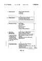
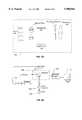
- FIG. 1is a block diagram of a system in accordance with an embodiment of the invention.
- FIG. 1Ashows the overall flow of how one may use an embodiment of the invention to scan an object, organize acquired points, fit geometric shapes to the organized point, manipulate the fitted geometric shapes, and display the resulting manipulated geometric shapes.
- FIG. 2is a more detailed block diagram of the system of FIG. 1.
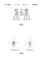
- FIGS. 3 and 3Ashow the physical arrangement of the FDV of the FIG. 1 system, and also shows how the FDV is coupled to the tripod by a fork mount.
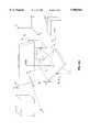
- FIG. 4shows an example coordinate system relative to the FDV of the FIG. 1 system.
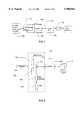
- FIG. 5is a block diagram of one embodiment of an FDV in accordance with the invention.
- FIG. 6is a block diagram of the optical transceiver of the FIG. 5 FDV.
- FIG. 6Ashows a dual mirror arrangement of the scanner shown in FIG. 6.
- FIG. 7is a block diagram which shows an embodiment of the laser.
- FIG. 7Ais a block diagram of the beam expander shown in FIG. 6.
- FIG. 8an embodiment of the duplexer.
- FIG. 8Ashows a partially-reflecting duplexer
- FIG. 9shows an embodiment of the window of the FIG. 8 duplexer.
- FIG. 10is a flowchart that shows calculations performed by the FDV DSP.
- FIGS. 11A and Bshow a unidirectional scan pattern and a bidirectional scan pattern, respectively.
- FIG. 12is a block diagram of an embodiment of the FDV processor.
- FIG. 13is a block diagram of circuitry for setting a desired position of an FDV mirror.
- FIG. 14is a block diagram of a signal conditioning and energy integration circuit of the timing circuit shown in FIG. 12.
- FIGS. 15 through 38illustrate the flow of CGP software.
- FIG. 39is a schematic diagram illustrating the framework of the computer graphics perception software utilized in the subject invention.
- FIG. 40is a diagram illustrating the mesh/mesh mutual cut operation used in the visual magic tool kit software of the subject invention.
- FIG. 1is a block diagram that illustrates the invention in its broadest aspect.
- a Field Digital Vision (FDV) module 10includes a scanning sensor for scanning an object 20 and for sensing the position in three-dimensional space of selected points on the surface of the object 20.
- the FDV module 10generates a point cloud 30 which represents the sensed positions of the selected points.
- the point cloud 30also represents other attributes of the sensed positions, such as reflectivity, surface color and texture.
- a Computer Graphics Perception (CGP) module 40interacts with the FDV to provide control and targeting functions for the FDV module 10 sensor.
- the CGP module 40uses the point cloud, the CGP module 40 recognizes geometric shapes represented by groups of points in the point cloud 30, and the CGP module generates a CGP model 42 that represents these geometric shapes. From the CGP model 42, the CGP module 40 generates a further model usable by computer-aided design (CAD) tools 50.
- CADcomputer-aided design
- the CAD toolsmay be conventional.
- FIG. 1Ashows the overall flow of how one may use an embodiment of the invention to scan an object, organize acquired points, fit geometric shapes to the organized point, manipulate the fitted geometric shapes, and display the resulting manipulated geometric shapes.
- the FDV 10includes a scanning laser system (lidar) 210 that scans points of the object 20 and that generates a lidar data signal that precisely represents the position in three-dimensional space of each scanned point.
- the lidar data signal for groups of scanned pointscollectively constitute the point cloud 30.
- a video system 220preferably including both wide angle and narrow angle CCD cameras, is provided.
- the wide angle CCD camera of the video system 220acquires a video image of the object 20 and provides, to the CGP 40 via a control/interface module 230 of the FDV 10, a signal that represents the acquired video image.
- the CGP 40In response to user input relative to the signal that represents the acquired video image, the CGP 40 provides a scanning control signal to the lidar 210, via the control/interface module 230, for controlling which points on the surface of the object 20 the lidar 210 scans. More particularly, the scanning control signal provided from the CGP 40 controls an accurate and repeatable beam steering mechanism to steer a laser beam of the lidar 210.
- the narrow angle CCD camera of the video system 220captures the intensity of the laser return from each laser impingement point, along with texture and color information, and provides this captured information to the CGP 40.
- the CGP 40is constituted of a data processing system (e.g., a notebook computer or a graphics workstation) and special purpose software that when executed configures the CGP 40 data processing system to perform the FDV 10 control and targeting functions, and also to perform the CGP model generation functions.
- a data processing systeme.g., a notebook computer or a graphics workstation
- special purpose softwarethat when executed configures the CGP 40 data processing system to perform the FDV 10 control and targeting functions, and also to perform the CGP model generation functions.
- the CGP 40controls the scanning lidar 210 of the FDV 10 by providing a lidar control signal to the FDV 10 that controls which points of the object 20 the FDV 10 scans.
- User inputis provided to the CGP which defines what portions of the object 20 to scan, and at what resolution.
- Each data point in the point cloud 30 generated by the FDVrepresents both distance to a corresponding laser impingement point from an FDV 10 "origin point” and the angle from the origin point to the laser impingement point.
- the CGP softwareconfigures the CGP 40 computer to process the data points of the point cloud 30, generated by the lidar 210 as a result of scanning the object 20, to display and visualize the scanned portions of the object 20. More specifically, the CGP software configures the CGP 40 computer to recognize geometric shapes in the object 20 ("graphic perception") and, using these recognized geometric shapes, to perform geometry construction, 3D model construction, 3D visualization, and database functions for automated acquisition or manual input of object attributes, generation of plans, sections, and dimensions, data query, and CAD interfaces, and networking options.
- FIG. 5is a block diagram of one embodiment of an FDV 10 in accordance with the invention.
- a lidar transceiver 502includes a laser, transmit optics, receive optics and detector for generating ranging and intensity data.
- a scanning system 504includes dual orthogonal scanning mirrors, galvo motors, and encoders for steering the laser beam and determining the azimuth and altitude angles of the laser beam from the positions of the mirrors.
- a wide angle video system 506generates targeting video information and a narrow angle video system 507 generates color and texture information. Control/interface circuitry handles the exchange of data between the FDV 10 and the CGP 40.
- the laseris preferably of the type disclosed in U.S. Pat. Nos. 5,132,977; 5,386,427; and 5,381,431, assigned to Massachusetts Institute of Technology.
- the beam generated by such a laserhas special properties such as being capable of producing pulse widths less than 1 nsec.
- the short pulsewidthprovides high accuracy, since radar theory shows that the accuracy is proportional to the inverse of the pulse time.
- the laser itselfis physically quite small, especially useful for portable applications.
- the beamcan be kept small over a large distance interval. In fact with a 1 cm exit aperture, the beam will remain less than 6 mm over 50 m.
- the laser beamis directed by the orthogonal scanner mirrors to a laser impingement point on the surface of the object 20.
- the rangecan be determined by any of a number of conventional lidar techniques. For example, the "time of flight" of a laser pulse to travel from the laser, and then back to the detector, is determined. The range is determined based on the constant speed of light, with appropriate adjustments being made for atmospheric factors.
- a system in accordance with the present inventioncan provide high ranging accuracy at high acquisition rates. For example, at 100 m ranges, a 1 mm accuracy can be achieved on a single shot basis, with anywhere from 1000 to 5000 data points being acquired per second.
- the FDV 10is physically housed in a box made of metal or other suitable housing material.
- the boxis suspended from its side panels by a fork mount mechanism.
- the fork mount systemis supported on a turntable, and the turntable is mountable on a tripod.
- the FDV 10can be rotated horizontally (“azimuth rotation") and vertically ("elevation tilt", or "altitude”).
- a position of the tripodis referred to as a "setting” or “positioning”
- the rotation and tilt of the FDV 10 in the fork mountis referred to as "pointing" or “orientation”.
- a "view”is generally associated with a given setting and orientation.
- the fork mount systempreferably includes high accuracy azimuth and altitude rotation measuring devices (e.g., conventional theodolite-type optical or electronic encoders) to provide precise rotation and tilt data of the FDV 10.
- high accuracy azimuth and altitude rotation measuring devicese.g., conventional theodolite-type optical or electronic encoders
- This featurecan allow the automatic integration of scans taken from the same tripod setting, but with a different orientation of the FDV. In the event these devices are not used, and for scans taken from different settings and orientations, these scans can be integrated using techniques described later in this disclosure.
- two orthogonal mirrors of the FDV 10provide a field of view of approximately 40° by 40° ("Field of View", or "View” is defined as the maximum size of the area projected by the laser maximum deflections of the beam in degrees).
- the field of viewcan be increased or decreased by resizing the mirrors and certain parts of the optical train.
- the fork mount described aboveis utilized to allow pointing of the FDV's 40° ⁇ 40° field of view anywhere over a projected sphere thus affording a wide range of flexibility in imaging large objects or groups of objects from the same setting. Other mounting methods may be used to accomplish the same purpose.
- High accuracy and repeatability electronic encodersread the rotational angles of the orthogonal mirrors, and the readings of the mirror rotation angles are precisely timed to coincide with the range reading.
- the systemis Class II FDA eye safe.
- a first embodimenthas ⁇ 6 mm spacial accuracy over a range of ⁇ 50 m.
- autofocus capability and 5-6 picosecond electronicsare included, which extends the system's range accuracy to ⁇ 1 mm and ⁇ 1 mm spacial accuracy over ⁇ 50 m.
- the range (and accuracy) of the systemcan be significantly influenced by the choice of eye safety classification selected, but these limitations are not inherent limitations of the invention itself.
- FIG. 6A block diagram of the optical transceiver 502 of the FDV 10 is shown in FIG. 6.
- the optical transceiver 502that transmits an optical pulse to a spot on target, and receiving a reflected optical pulse for the target. Given the constant speed of light, the optical transceiver calibrates the distance to the spot on the target.
- the laserfires an optical pulse which lasts less than 250 psec in response to an external command provided from a laser controller 604.
- the laser 602produces a pulse, preferably at a wavelength of 532 nm, within 100-300 ⁇ secs after an external signal emanating from a digital signal processor which provides central control of real time events.
- the time delayis a complicated function of recent laser history and environmental conditions. This function is not completely known at present. However, a software algorithm, which is described elsewhere, is employed to estimate the time delay with adequate accuracy for the required measurements.
- the laser beam output of the laser 602is transmitted through a beam expander 606 that is focused to adjust the size of a light spot that will eventually impinge upon a point on the object 20.
- the focussed optical pulseis then transmitted through a duplexer 608, which is an optical system for aligning the outgoing optical path with the incoming optical path.
- the duplexer 608directs a significant first portion of the light energy of the outgoing optical pulse to spot on the object 20 via a scanner 614, but a second, much smaller portion, of the light energy of the outgoing optical pulse is directed to a receiver telescope 610.
- the portion of the outgoing optical pulse that propagates to the object 20impinges on the spot on the object 20, and some of the energy of the optical pulse is reflected off the object 20 in a direction back to the duplexer 608.
- the returning optical pulseis directed by the duplexer 608 to a receiver telescope 610, which focuses the received energy onto a detector 612.
- the detector 612converts the received optical pulse energy into electrical energy, and the output of the detector 612 is a series of electrical pulses, the first (which is generated by the detector 612 in response to the second, small portion, of the transmitted pulse not directed toward the object 20) occurs at a short fixed (i.e., fixed by the length of the optical path through the beam expander 606, the duplexer 608 and the receiver telescope 610) and the second of which occurs as light energy returns from the object 20.
- Both the second, small portion of the transmitted pulse not directed toward the object, and the return optical pulse reflected from the spot on the objectare provided to the timing circuit 616 which calculates the time of flight to the spot on the object. The range to the spot on the object can then be readily calculated from the calculated time of flight.
- FIG. 7is a block diagram which shows an embodiment of the laser 602.
- the heart of the laser system 602is a conventional laser chip 702 that include two bonded crystals coated with antireflective dielectric coatings on their faces.
- the laser chip 602is pumped with a solid state diode 704 operating at 808.5 nm ⁇ 3 nm.
- the output frequency of the diode pump 704is adjusted by changing its temperature with a thermoelectric cooler 706.
- the temperature of the pump diode 704is measured with a thermistor 708, and the measured temperature is fed back into the diode power supply 710.
- the required temperaturevaries with each individual diode, but it typically ranges from 20° to 30° C.
- the output power of the pump diodeis typically 1 watt, launched into a 100 ⁇ m core glass fiber.
- the output of the crystal laseris approximately 35 mw average power at 1.064 ⁇ m, which corresponds to 1 ⁇ J pulses lasting about 280 psec at a repetition rate of 10 KHz.
- the multimode fiberis preferably terminated by an SMA905 solid brass connector, with the crystal of the laser chip 702 is glued to one end of the connector with an optical resin.
- a piece of KTP frequency doubling crystal 712is held within a few millimeters of the face of the laser chip crystal 702. This provides an ultimate output from the laser 602 having a 12 mw average power at 532 nm, which corresponds to 0.8 mJ pulses lasting approximately 218 psec. This ultimate output from the laser 602 is nearly diffraction limited (i.e., one which has theoretically minimum divergence, given a specific wavelength and waist diameter), with an apparent waist diameter of 56 m.
- Embodiments of the inventionmeet FDA Class II eye safe system design specifications are potentially more commercially viable.
- the maximum energy per pulse that can be transmitted at 532 nmis 0.2 ⁇ J.
- the average power transmittedis largely dependent on the pulse repetition rate, and is given by the following table
- the beam expander 606is entirely conventional (e.g., Melles Griot model number 09LBM013, 10 ⁇ beam expander).
- the transceiverhas cross axis accuracy which is proportional to the size of the laser beam impinging on the intended target.
- the base design of 6mm accuracyhas a simple beam expander.
- the lasercan be collimated with a fixed 10 ⁇ beam expander which has an aperture of ⁇ 1 cm to produce a beam whose 1/e 2*power beam width is less than 6 mm over a range of 50 m.
- FIG. 7Ashows a further embodiment 750 of the beam expander 606 that includes features which allow the system of the invention to measure ranges at an accuracy of approximately 1 mm at 50 m. This is because the impingement spot on the object 20 of the laser beam expanded by a conventional beam expander is collimated, and produces a spot of no more than 6 mm over a 50 m range. However, a beam can be focused through a 50 mm aperture to a spot of size no more than 1 mm over a 50 m range--but the spot will be much larger at other ranges.
- the beam expander 606 of a system having 1 mm accuracy at 50 mincludes a movable optical element 752 which can change the size of the focused spot.
- the beam expander 606includes an adjustable aperture, and means for controlling the adjustment, so that the distance, from the laser, over which the beam stays at 1 mm in diameter remains approximately constant.
- f/Dis held constant, the depth of focus will not be a function of the range of the focused spot, f.
- a linear servo motor(see FIG. 7) is employed for controlling the position of the focusing mechanism, and a transducer provides position feedback.
- the lensis mounted in an annular ring, which prevents it from rotating or misaligning while it is being translated.
- FIG. 8An embodiment of the duplexer 608 is shown in FIG. 8.
- the optical system of the duplexer 608is configured such that the outgoing beam from the beam expander 606 to the scanner 614 is coaxial with the return beam reflected from the object 20. Thus, only one scanner 614 need be provided.
- a window 802is provided, with a 50% beamsplitter 804 attached over the window 802. When an optical pulse is transmitted from the laser 602 and through the beam expander 606, the pulse impinges upon the beam splitter 804.
- a partially-reflecting duplexer 850is employed. With this duplexer, a fraction of the light pulse provided from the beam expander proceeds through the window to the receiver telescope 610, and can be used for other purposes such as for calibration. The remainder of the light pulse proceeds to the object 20. Most of the return light pulse from the object 20 continues on through the window and is collected by the receiver telescope 610.
- the windowis AR coated on the receiver side, and partially mirrored on the laser side. The entire window is used to steer the outgoing beam, since a 50 mm aperture is required to focus the spot to 1 mm at 50 m.
- the partial reflectanceis chosen in view of the laser transmission power and the applicable eye-safe classification level. For example, if the laser transmission power is four times the allowable level of the applicable eye-safe level, then the partial mirroring is chosen to reflect 25% and absorb 75%.
- the laser 602emits a strongly polarized beam so that the reflective coating can be optimized to have slightly different reflection coefficients for the two planar polarizations (20%-S and 30%-P).
- the power of the beam impinged onto the object 20can be fine tuned merely by physically rotating the laser body.
- the receiver telescope 610may be a simple 50 mm aperture lens.
- the lensis preferably selected so that the variation in pulse energy entering the detector does not change as a function of the distance to the target over the range of distances for which the instrument is designed.
- a multiple element lenscan be designed to minimize the variation in received pulse energy as a function of range somewhat more effectively than a single element lens. That is, at the greatest expected distance, the focal length of the lens is such that all the incoming light, which is effectively collimated since it is generated by a point source in the far field, is focused to completely fill the detector.
- the receiver opticscan be improved in some cases by using a two element, adjustable focus, newtonian telescope (e.g., similar to the 1 mm beam expander).
- the detector 612converts optical pulses to electrical pulses which can be processed by the elapsed time measurement electronics (timing circuit 616).
- the detector 612is an avalanche photodiode (APD) with greater than 1 GHz electrical bandwidth.
- APDavalanche photodiode
- the intensities of all the pulsesare recorded. The intensity information is used to make a correction to the range measurement derived from the timing information.
- the scanner 614may be conventional.
- the scanner 614directs the outgoing pulses from the duplexer 608 to a desired position on the object 20 and directs the incoming return pulse into the receiver telescope 610.
- the scanner 614directs light to the narrow field ccd camera to collect color and texture in the immediate vicinity of the scanned laser points, which provides for precise registration of color and texture obtained with the lidar acquired point geometry.
- the scanner 614includes a dual mirror arrangement (see FIG. 6A) for beam steering, although any conventional high accuracy and repeatability beam steering mechanism may be employed.
- the dual mirror arrangementincludes two mirrors which are rotated on orthogonal axes by moving coil motors. These motors have an integral position decoder which has angular repeatability of less than 1 microradian.
- the mount for the scannersis integrally formed with the supports for the laser and other optics. This system provides 40 degrees of optical motion in both altitude (elevation) and azimuth at several hertz.
- the function of the timing circuitis to accept the output signal of an Avalanche Photo Diode (APD) and to provide data from which the relative times between electrical pulses can be calculated.
- APDAvalanche Photo Diode
- Relative Time DataFor each input pulse sequence, up to 3 sets of 9 bytes each to calculate 3 relative times.
- PurposeProvide data which can be used to compensate the relative time measurements for effects due to the amplitudes of pulses in the received sequence.
- Receiver CommandsSet threshold DAC, Set Hysteresis DAC, Set Holdoff Delay, Set Full Scale Time, Set Control Byte, Reset, Enable, Read Status byte, Read Data Byte Count, Read Next Data Byte
- APD Power Connector9 pin subminiature D receptacle supplying +12V at 120 mA
- a digital signal processor integrated circuitcontrols all the time critical functions of the FDV--scanner control, laser firing. It also provides fast floating point computation capability for making geometry corrections, calibration corrections, and video lens corrections, and video compression.
- the digital signal processoris interrupted at regular time intervals, typically about 10 usec. At each of these time intervals, a check is made to see what real time calculations are outstanding.
- the electronics for the scannerare a simple precision PID controller which are driven by a digital signal from the DSP.
- the controller circuitdoes not have an error signal output.
- An external precision analog differential amplifierprovides an error signal (the difference between the command signal and the actual displacement), which is sampled by the DSP at low resolution.
- the DSPthen computes the exact scan position by computing the sum of the command signal and the error signal.
- the digital signal processorgenerates the trajectories for the analog scanner controller, and makes measurements of the difference between the desired trajectory and the actual position. It predicts the time at which the laser pump is turned on so that the laser will fire at the desired angle. These predictions are made at regular time intervals.
- FIG. 10is a flow chart that shows the calculations performed at each time interval.
- the userdefines areas within the view of the scanner that are to be scanned, and indicates the density of points to sample within the scanned region.
- the objective of picking a good trajectoryare the conflicting needs of doing the move quickly and accurately.
- Accurate movementrequires minimum torque, which would otherwise deform the apparatus. This limits the speed with which motions can be made.
- a calculationis performed to determine the current position of each mirror. The particular calculation used depends upon the type of scanning employed.
- scanningis uni-directional (i.e., always proceeds from left to right, or right to left, on parallel lines).
- FIG. 11Ashows such a unidirectional scan pattern.
- the scan mirrorretraces to the beginning of the next line without making any range measurements. The retrace can proceed quite quickly since no measurements are being made during the retrace.
- FIG. 11Bshows such a bi-directional scan pattern. This is not as efficient as it might seem because the retrace time is used for other calculations, and because the resulting scan pattern is not as regular.
- Both raster scanning methodsrequire traversing a straight line in the minimum time, starting at zero velocity and ending at zero velocity.
- the torque applied to the mirroris proportional to the angular acceleration, which must zero at the beginning and end of the scan since the mirror is at rest. It can be shown that the trajectory that makes such a minimum energy move between two points is given by the sum of a straight line and a full cycle of a sin.
- a disadvantage of raster scanningis that since the speed of the trajectory is varying, the scanning efficiency is not optimal.
- a spiral patterncan achieve a constant speed trajectory which permits a uniform point distribution.
- the systemIn addition to scanning a range image, the system is capable of performing a number of functions which are common in surveying.
- the scannercan be made to search for important features, or locations of high reflectivities. This allows the system to perform normal surveying functions by finding a target whose location is approximated identified, and reporting its exact angles and position.
- the capacitive encoders in the moving coil motorshave tremendous repeatability, but relatively poor accuracy. A number of calibration activities need to be continuously performed to ensure system accuracy.
- each scanneris calibrated over its complete range of angles.
- a mapis created and stored of the measurements of apparent angles for thousands of accurately measured points using an external resolver that is traceable to NBS standards.
- the DSPlinearly interpolates between these measured points on every angle measurement.
- the accuracy of angle measurementis improved by determining scale or offset errors in the encoder during operation. Two methods are described.
- a first methodis to provide a pair of mechanical stops on the scanner shaft. Periodically, the scanner is driven into these mechanical stops with a known force (current), and a measurement is taken of the apparent angle. These two measurements provide an accurate gauge of any scale or offset errors in the encoder.
- a second methodis to install a pair of autocollimators at two stable angles pointing at the back side of the mirrors. An autocollimator gives a very accurate reading when the mirror is close to perpendicular to its optic axis, and can give resolution better than 1 ⁇ rad. The mirror is adjusted until it comes perpendicular to each autocollimator in turn, and this permits estimating any required scale or offset adjustments.
- a circuitis added to estimate the energy in each detected pulse, and a table of corrections is maintained to improve the range estimates.
- Two different circuitshave been employed to make a measurement of the pulse energy for this purpose.
- the firstis a gated integrator, the gate being open at the beginning of a pulse, and closed at the end.
- the secondconsists of an integrator with a time constant scaled to the width of the pulse, followed by a peak detector which has a time constant much longer than the pulse width. The output of the peak detector is sampled shortly after the pulse is detected.
- a 20 m single mode fiberis provided in the optical path to provide range system checks, and to calibrate the timing circuits.
- One end of the fiberis placed in the transmit path, and is either obscured partially or completely by a movable aperture.
- the far end of the fiberis aimed into the lidar receiver aperture.
- the fiber itselfmay be coated at both ends, so that a single pulse introduced into the system can produce multiple output pulses, all with extremely repeatable intervals. Individual pulses in the train can be distinguished by setting a range gate in the timing circuit which ignores all received pulses before a programmable length of time.
- the precise delay of the fiberprovides an accurate calibration of the gain and offset errors in the timing circuit. This intermittent calibration is used in all subsequent range measurements.
- the energy of the detected pulsescan be varied over the dynamic range of the receiver, at one particular time delay.
- the intensity and the measured time valuesproduce a map of the range walk correction required for each intensity, and this correction is applied to subsequent measurements.
- This correctioncan provide accuracy of 1 mm over the dynamic range of the instrument, particularly as a result of the great repeatability of the laser pulse waveform.
- the output of the FDV after a range scanconsists of points in spherical coordinates with respect to a coordinate system in the scanner.
- the raw dataconsists of mirror angles and time intervals.
- the DSPcomputes the spherical coordinates of the scanned points by taking into account scanner geometry (mirror thickness, optic axes, mirror offsets, etc.) and all the appropriate calibration adjustments.
- the digital signal processoris responsible for controlling the firing of the pulsed laser, but it can only do so indirectly.
- the processorhas control of the timing for starting the pump diode, which causes the passive q-switch to fire after saturation has occurred.
- the delayis a function of junction temperature, which in turn is a complex function of ambient temperature and recent history of laser firing.
- the delaygenerally ranges between 100-300 usecs.
- the pump delaydoes not change quickly if the firing rate does not change quickly.
- accuracy of a few microsecondscan be achieved by estimating the next pump delay to be the same as that in the previous firing cycle.
- the digital signal processormeasures the pump delay by reading an internal counter when the pump is started and when the laser actually fires, causing an interrupt. Since the interrupt latency is less than a microsecond, this becomes the timing accuracy to which the pump delay can be measured.
- the decision to fire the laseramounts to computing the time at which point the pump diode is started.
- the FDVis designed to perform under the control of a remote host computer which contains graphical controls for a user to specify areas to be scanned.
- the remote machinecontrols the FDV through a bidirectional serial byte stream, which is effected in any of a number of media: ethernet, EPP parallel port, serial port.
- a processor in the FDVis assigned the task of decoding messages, and scheduling the required activity.
- FIG. 12is a block diagram of the FDV processor.
- the host machineacts as a master, sending a well defined message protocol to command the FDV.
- the FDVresponds with data and status information.
- actions which can be requestedare:
- each scanner in the dual mirror systemrequires a 16 to 18 bit digital word to set the desired position, which is applied to a precision digital to analog converter to create a voltage proportional to the desired position.
- a precision digital to analog converterto create a voltage proportional to the desired position.
- a precision difference signalis generated, and the difference is measured to 12 bit accuracy. This provides an economic method of making 18 bit position measurements while only using an inexpensive 12 bit converter.
- Two methodshave been developed for this purpose: an optical and a mechanical means.
- the scanner shaftis gently placed against one of two mechanical stops, and the current in the scanner controller is adjusted to a specific value, which provides a known force.
- the position signalis adjusted until there is no position error, and this gives the calibrated position measurement.
- two autocollimatorsare aimed at the back of the scanner mirrors, which have also been polished and mirror coated. When the scanner mirrors are exactly aligned with one of the collimators, the output from the split photodetector in the autocollimator is balanced. By placing the scanner in each of these precise angles in turn, an offset and scale correction for the scanner encoder can be calculated.
- the purpose of the timing circuitis to provide the relative time between the start pulse and the stop pulse, in picoseconds.
- a signal conditioning and energy integration circuitan embodiment of which is shown in FIG. 14
- a time interval analyzerBoth communicate directly with the DSP.
- systemshave been produced with a commercial timing instrument, the Stanford Research Systems SR620 time interval analyzer.
- the interface to this instrumentis through an IEEE488 interface.
- the communications interface to the Stanford Research Systems SR620 time interval analyzeris IEEE488.
- a custom time interval measurement circuithas been developed which utilizes a separately patented interpolation technology.
- the circuitemploys a clock, typically operating at >100 mhz, which is used to make a coarse count of 10 nsec intervals between stop and start pulses. Additionally, there is an interpolator which divides each 10 nsec coarse count into 1000 smaller increments, providing 10 psec resolution. This system has approximately 5 psec jitter. Differential time measurements can be made with less than 20 psec RMS error, which corresponds to about 3 mm.
- This circuitcommunicates with the DSP using a dedicated serial bus, and employs a packet protocol: the DSP arms the circuit by sending a single byte. When the timing circuit completes its task, it sends a sequence of bytes which represent both the time delay between start and stop pulses, and the intensity of each pulse.
- the DSPhas three lines for laser control: one starts the laser pump, the second indicates that the laser has fired, and the third indicates that the return pulse from a target has been detected.
- the DSPsamples the analog pulse amplitude signal. This happens typically within 1 ⁇ sec.
- the useris provided on the host a video representation of the scene from which he can choose a portion to be range scanned. In most cases this will correspond to the scene rendered in ambient illumination.
- a second approachis to utilize standard commercial CCD video cameras to acquire an image.
- One CCD camera with a wide angle lensis aligned with the range scanner with as small an offset as possible.
- a second camera with a 5 degree field of viewis placed so that its optic axis is coaxial with the transceiver.
- a much smaller field of viewis accessible through the scanner, and can be scanned with the same resolution as the transceiver. This allows targeting small or distant objects.
- the wide angle lensintroduces a fish-bowl effect in the image captured by the CCD sitting behind the lens. Straight lines in the world are not straight in the image. This distortion increases with the distance from the center of the lens. This distortion is removed by comparing the image the camera produces when aimed at a carefully designed and printed calibration target image. The difference in the anticipated image and the recorded image provides the information needed to warp subsequently acquired images to eliminate the distortion.
- Each video imageis compressed prior to transfer.
- JPEG standard image compressionIt is relatively fast, and creates reasonably small compressed images for communication.
- Another desirable featureis that the algorithm operates on blocks, which permits us to do interleave image capture, alignment, compression, and transmission in parallel--significantly enhancing throughput.
- a second camerawith a narrow field of view (e.g., approximately 5°) is placed such that it is coaxial with the scanning laser beam.
- the field of viewis adjusted so that the pixel resolution is approximately the same as the voxel resolution of the lidar system.
- the cameracan be operated while the laser is activated. When this is done, a small group of pixels will be illuminated by the laser, and the centroid of these pixels will correspond to the point which would be measured by the lidar.
- a video imageis captured, it can be mapped onto a surface which is estimated by a lidar scan.
- the FDV 10is preferably controlled by the CGP 40 computer.
- the CGP 40 computerBy interacting with a display of the CGP 40 computer, not only can the FDV targeting be controlled, but also the scanned points can be displayed. This facilitates the CGP modeling functions. These functions are performed in two windows which divide the computer display screen. The first window shows the video image of the target scene (the Video Window or Targeting Window); the second shows the scanned points and later the constructed model (the Scanned Point Window or Model Window).
- the innovations mentioned abovewill be detailed below and in the CGP section.
- the time required to scan the object 20can be minimized. For example, in general, it is not required to scan the entire object 20 at a high resolution in order to accurately model the object, even when high detail is required. In particular, many objects are formed of regular geometry, such as planes or cylinders that can be scanned highly accurately at low resolution. Even when an area of the object 20 is scanned at lower resolution, the actual accuracy of each point (in terms of its relative location to all other points in the frame) is still as high as the maximum accuracy of the system.
- multiple scans of varying resolutionsmay be performed within the same view.
- the automated FDV interface, targeting, control and display systemgives the user, in the targeting window of the CGP 40 computer display, tools such as pull down menus and stretch bounding boxes to graphically identify the areas of interest and their desired resolution.
- the FDV 10can acquire up to 1000 ⁇ 1000 points per scan frame (defined as the collection of scanned points in a given bounding box).
- a viewcan have as many scan frames (or scans) as desired, but may be limited by the amount of memory installed in a particular embodiment of the CGP 40 computer.
- the FDVis first pointed in the general direction of an object to be measured.
- the targeting CCD cameracaptures a video frame of the target area and displays it on the target window of the computer screen.
- the FDV's fork mount's rotation and tilt abilitycan be used to make final pointing adjustments prior to scanning. In that event a new video frame is acquired for targeting the adjusted area.
- the softwareconfigures the CGP 40 computer to allow the user to start modeling (replacing scanned points with geometric surfaces such as triangulated meshes, planes, cylinders etc) within the model window even while the FDV continues to scan the object. That is, the user can start the modeling process even after only the first scan frame is acquired.
- the softwareconfigures the CGP 40 computer to perform such tasks as basic object surface fitting tools and semi-automated surface recognition tools to be used in completing the model.
- the CGP software and its toolsare more fully described in another section of this document.
- Non-geometric "attribute data" relating to the objects in the scenesuch as component specifications, affixed to components of the object by a bar code or other label, can be acquired during the scan and associated with the particular component in the CGP model.
- the resulting modelcan be viewed and queried within the model window in a variety of ways and it can be uploaded to any of a umber of CAD programs for further editing or design.
- the CGPis comprised of a suite of software modules running on a portable PC computer or a graphics workstation (CGP Computer).
- the CGP softwareutilizes standard graphics libraries and database functionality operating on a personal computer or workstation.
- the CGPallows the user to perform real time 3D data acquisition and modeling in the field.
- the CGP software's functionalityincludes FDV control, targeting and data acquisition; display and visualization of scanned points; surface segmentation and fitting; manual 3D CAD model construction; 3D visualization; interaction with part and model databases; and the ability to export data in standard data exchange formats to other CAD systems for further processing.
- FDV controltargeting and data acquisition
- display and visualization of scanned pointssurface segmentation and fitting
- manual 3D CAD model construction3D visualization
- interaction with part and model databasesand the ability to export data in standard data exchange formats to other CAD systems for further processing.
- the CGP softwarehas many additional innovations which will be obvious from the following description of the software system.
- the data acquisition and modeling processdivides into the following steps: scan control, point acquisition, segmentation, geometry fitting, geometry manipulation, scene integration, model annotation, and geometry display and query. Each step of this process is described individually below.
- a first type of window 10displays a video image of the target scene used to define regions to be scanned by the FDV.
- a second type of window 20displays an interactive 3D model consisting of the scanned points and constructed surface geometry; multiple views of the same model may be displayed simultaneously.
- the CGPprovides additional windows for controlling the FDV hardware, indicating status parameters of the system, and interacting with any number of external CAD and database systems.
- scan controlis the process of indicating which portions of a real world scene are to be scanned.
- Scan controlis performed using a video image of the scene 10.
- the video imaging devicetypically a simple video camera
- the video imaging deviceprovides an image of the real world scene on the computer display which the user, using a pointing device such as a mouse, indicates a region to be scanned. This region is delineated by any of a number of well known computer graphics techniques such as dragging out a rectangle 15 bounding the region to be scanned.
- the userindicates the density of the scanning operation by defining either the number of samples in each direction or the angular separation between adjacent samples.
- the computerthen translates such region and scan resolution information into a set of commands for the scanner. These commands are communicated to the FDV which is assumed to perform the commands, gather the desired data, and return the scanned data 25 to the CGP for display and further processing.
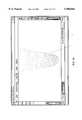
- the data returned from the FDVconsists of an ordered grid of three dimensional points 25. Each point consists of its coordinates in three-space as well a measurement of the intensity of the reflected laser pulse at that point. Each point returned is displayed in the data window 20 as it is generated by the FDV at its three dimensional location. In addition, each point may be color mapped to the intensity of the reflected laser pulse at that point.
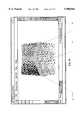
- the display of the intensity information(FIG. 37) provides a more intuitive understanding of the shape of the targeted object than that provided by the uniform intensity display of points (FIG. 36).
- This intensity displaymay be used as a precisely aligned low resolution video image of the exact view of the scanner to delineate the area of additional scans to be taken.
- the ordered grid of points generated in this manneris referred to as a scan field.
- Multiple, possibly overlapping scan fieldsmay be gathered and simultaneously displayed in the manner disclosed above.
- the collection of such scan fieldscan be readily manipulated and viewed (see Geometry Display and Query below) as a rigid three dimensional object.
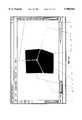
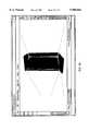
- Segmentationis the process of grouping points whose surface type is represented in the software by a geometric primitive and cutting such points to isolate them as a new set.
- FIG. 17which describes a scan of a corner of a room
- a scan fieldis initially a single entity.
- a subset of the points in a scan fieldcan be delineated using standard computer graphic techniques such as outlining a polygonal domain 10.
- subsets of points 11, 12, and 13 which have been cut from a scan fieldare displayed in a different color and are stored as distinct and independent scan fields.
- the three subsets of pointshave been selected in such a manner that each subset belongs uniquely to one of three planes making up the corner of the room.
- the segmentation processcan be automated.
- One embodiment of such automatic segmentationapplies coplanarity tests to identify groups of points which can be described within a fixed tolerance by a single plane.
- groups of pointscan be identified that lie on a single cylindrical surface.
- Automatic segmentationcan be combined with geometry fitting (disclosed below) to generate surfaces from scan fields with minimal user interaction.
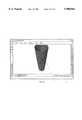
- a geometric description of the surface(s) represented by that scan fieldcan be obtained by creating a triangulated mesh connecting adjacent points. Any of a number of standard mesh generation techniques well known in the art may be applied to the scan field. In the preferred embodiment, adjacent points are connected by triangles only when the depth differences of such points do not exceed a fixed threshold set by the user.
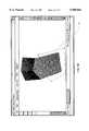
- a scan of a statuette of a horse sitting atop a boxcan be rapidly converted into a surface mesh (FIG. 38).
- This representationis particularly appropriate for complex surfaces such as natural terrain which cannot be approximated by simple geometric primitives.
- Geometrical primitivessuch as planes, cylinders, etc.
- Geometrical primitivescan be used to replace groups of scanned points using known geometric fitting algorithms thereby providing the best fit between the selected points and the chosen primitive.
- the new surfacecan be colored and rendered and the user can invoke commands to allow the calculation and display of statistics relating to how well the fit has been performed.
- the usercan also perform measurements such as radius of a cylinder or the location of the primitive relative to other objects in the data window.
- the scan fields 11, 12, and 13 defined in FIG. 19,have been fit (as shown in FIG. 20) with planar patches 21, 22, and 23.
- a set of points 31can be converted into a best fit cylinder 41 at the request of the user.
- the three dimensional CAD model of FIG. 32can be constructed.
- the CGPprovides a method permitting an operator to automatically and rapidly fit a group of points representing an object in the view (such as a valve or a flange) with a predefined geometric model of the real object.
- the predefined modelcan be an item from a manufacturer's catalog having a three dimensional graphical representation of the object or an object previously generated using the CGP's modeling capabilities.
- predefined partscan be associated with additional database information such as model number, date of manufacture, or maintenance records.
- Modelingis the process of turning points and their attributes into meaningful computer graphical representations of reality that can be used for a variety of purposes such as graphical visualization and design.
- an objectmay include information regarding the connectivity to its immediate neighbors. For example, a pipe might indicate that it connects to a valve, or a plane representing the ceiling of a room might indicate its connection to four supporting walls.
- a usercan indicate connectivity between geometric primitives by extending and intersecting those primitives. For example, with reference to FIGS. 20, 21, and 22, the user can generate the precise location of a corner point in a room by intersecting the planes representing two walls and a ceiling.
- the userhas generated the floor plane 21 and two wall planes 22 and 23 using the geometry fitting techniques disclosed above.
- the CGPhas generated the lines of intersection of pairs of these planes.
- intersection line 31is the geometric intersection computed mathematically from the intersection of lines 21 and 22.
- lines 32 and 33were generated by the intersection of pairs of planes 21, 23 and 22, 23 respectively.
- the planescan then be extended to the lines of intersection by projecting the convex hull of a planar region onto the intersection line of that plane with another plane.
- planes 21 and 22 of FIG. 21are extended to line, 31 of FIG. 21 to generate planes 41 and 42 of FIG. 22.
- the processcan be integrated in a single tool requiring only one user interaction.
- the automated corner tooltakes a scan field 5, segments the points as disclosed above, fits three planes to the scan fields, merges them in their respective intersection lines, and thus defines the complete geometrical corner as shown in FIG. 23. Note that the only user interaction required was to define a scan field that covers just a single corner.
- cylinderscan be extended as far as the intersection point of their axis with another primitive such as a plane.
- a planeWith respect to FIG. 26, the user can extend cylinder 20 as far as necessary so that its axis ends in the two planes 11 and 12. The result of this operation is indicated in FIG. 27 as cylinder 30.
- cylinderscan be extended to a mutual point of intersection between their respective axes, or, if such an intersection point does not exist, the points of closest proximity between the two axes.
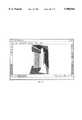
- FIG. 33displays a scan field containing a collection of pipes and elbows joining those pipes.
- FIG. 34demonstrates the best-fitting pipes generated by the user using segmentation and fitting techniques disclosed above.
- an arc of a specified radiusis determined and fit between the two lines representing the axes of the two pipe segments (for examples, segments 20 and 21 of FIG. 34); a suitable piece of a torus is then constructed around this arc segment, and the two pipe segments are extended to join smoothly with the ends of this elbow part as shown in FIG. 35.
- Scan fields taken in the same field of view of the scannerare inherently registered with respect to the same shared 3D space. If, however, the FDV is moved between scanning operations, additional effort is required to construct a consistent, combined CAD model. Scan fields taken from different scanner positions must be registered based on suitable primitives viewed from both positions.
- the first methodis based on the fact that two views of the same object can be registered by matching three non-degenerate planes in each view. For example, if a particular corner of a room consisting of two walls and the ceiling is visible in two separate scans taken from different scanner positions, the two scenes can be positioned so as to align each of the wall and ceiling surfaces.
- the second methoduses overlapping regions of arbitrary surfaces and uses an iterative, global minimization technique to find the relative positioning parameters between the two views which minimize the distances between the surfaces of one view and those of the other as described in Turk and Levoy, "Zippered Polygon Meshes from Range Images", SIGGRAPH 1994.
- individual parts in the above geometrical modelcan be annotated with additional, possibly non-geometric, information such as material references, part numbers, and references to external databases and catalogues.
- This informationcan be entered manually by the user or alternatively can be generated automatically by using the scanner to read suitable bar code or character information from the real world object being scanned.
- this additional informationis stored in an external database, the user may click on an individual part in the geometrical model and recover such additional information through other windows. Similarly, queries may be made of the database requesting all parts which meet some selection criteria to be highlighted.
- Access to the geometrical CAD modelis available to the user through an interactive state-of-the-art computer graphics renderer.
- this rendereris the ability to manipulate the CAD model using standard graphical interaction techniques such as a crystal ball interface or interactive fly-through.
- the usermay choose to selectively view certain portions of the model either by placing objects in separate ⁇ layers ⁇ and viewing only selected layers, limiting the geometrical extent with clipping planes, or choosing to view symbolic abstractions of certain geometrical parts such as the isometric center lines of cylindrical pipes.
- Geometric attributes of the modelmay be extracted in an interactive manner. Coordinates of individual points, distances between geometric primitives, and angles between the normals of different facets are readily available to the user.
- the resulting modelcan be uploaded to any of a number of CAD programs for further editing or design.
- Geometryis represented initially as a cloud of points; later as a mesh, as a detailed model copied from a library or catalog, or as simplified model generated interactively.
- This geometrycan be enhanced with color, intensity, texture, or even video information which gets added to the individual surfaces of the element.
- tagscan be provided with tags or "layer" information for classification purposes.
- the usermay choose tags from previously defined hierarchical menus; e.g., the choices at a first level night be:
- Arbitrary textual informationcan be attached to each element via a text window. This may contain summary information from a catalog or notes concerning the modeling.
- Elementscan be linked to other information contained in external databases, such as the type of a valve or pump, its ratings, its manufacturer, its maintenance schedule. This information in the external database may be in the form of a hyperlinked database.
- the systemprovides the capabilities to control the scan management and the video gathering. Later we may provide a user interface to provide more selective ways of indicating the areas that need to be scanned: one option is the "thick-brush" paradigm in which the user outlines the features that should be incorporated in the model; the system then goes and finds the corresponding features in the world and automatically selects a suitable scan region for the chosen edge, pipe, or I-beam.
- the systemprovides the capabilities for efficient multi-tasking, so that several windows can be opened simultaneously, providing views into one or more catalogs or databases, while a scanning process or a modeling operation are under way.
- These elementscan be provided with color, intensity, texture, or texture map information. Other attributes can be assigned to these objects, and various kind of linkages can be established.
- Sets of objectscan be selected interactively and grouped hierarchically.
- Pairwise view alignmentbased on registration features or based on an optimization process that tries to register the overlapping portions of two meshes by minimizing their mutual distances.
- Geometrical informationcan be extracted from the model at any time. Cut sections can be created, and distances between two points or angles between to planes can be extracted.
- the attribute information associated with that elementscan be fetched from the database. If this information is large and organized in a hyperlinked document format, then the corresponding database browser will be opened and the root page for this object will be presented.
- Data generated within the CYRAX CGPcan be exported in an ASCII text format in the form of ".crx" files.
- the crx formatshould be able to encode all information that is self-contained within a CYRAX model. This should allow sophisticated users to build external programs that can search CYRAX models for specialized analyses (such as counting all elements of a particular type) or to make global modifications to such a model (e.g., replace all I-beams of a particular type) without the need to go through any other database system.
- Cyra Technologies' Field Digital Vision (FDV) unitprovides portable, rapid, and accurate laser range scanning technology in the field.
- the FDVlike a three-dimensional camera, is pointed at a target which it then scans to generate a range image.
- a range imageis like a digital photographic image except that each pixel of the image is a point in space rather than a colored two-dimensional point.
- the FDVpermits a user to rapidly gather three-dimensional data about an object by gathering thousands of points from that object.
- the Computer Graphics Perception (CGP) software kitprovides the functionality necessary to convert collections of range images into three-dimensional, intelligent models. These models can be generated by surveyors as the FDV generates the range images or can be Generated in the office by CAD operators from gathered data. Because of the wide range of modelling tasks. Requirements, and paradigms within the various three-dimensional modelling communities, the CGP is designed to support a general framework which can be integrated easily with standard CAD tools, facility management software, and intelligent modelling environments.
- the functionality of the CGPtakes you from range image to complete, annotated, intelligent models.
- the structure, detail, and content of the resulting modelis under the complete control of the user allowing the generation of ten minute rapid visualization models to multi-layer, intelligent facility documentation models.
- the various forms of modelling availableintegrate easily and consistently to permit highly detailed and annotated submodels of interest to coexist with low resolution, automatically generated shrink-wrap models of ⁇ context ⁇ structures intended only to aid in visualization.
- the CGPis structured around a database (FIG. 39).
- the data stored in the databasecan come from a variety sources including raw range scans and video images generated by the FDV, geometric entities generated by the CGP modelling process, geometric entities and associated product information imported from catalogues, and annotation data such as facility maintenance information.
- Data within the databaseis classified as either ⁇ internal ⁇ or external ⁇ data depending upon whether the content of the data is meaningful to the CGP system.
- Internal datasuch as geometry, scan points, and geometric annotations is used directly by the CGP is general purpose data required to meet the modelling needs of a wide range of user communities.
- External data stored in the databasehas meaning only in the context of general database queries or external, application specific software.
- Examples of external datainclude the date a pump in a chemical plant was serviced, the manufacturer of a particular part, or a pointer to the home page of the designer of an architectural subsystem. While internal data can reference external data elements, the CGP has no way to understand, manipulate, or present this data and must rely on external queries and external packages to make use of it. A more complete description of this concept is presented in the section "Intelligent Modeling".
- the reality acquisition processsubdivides into two processes: scanning and modelling.
- the CGPprovides all of the necessary controls to operate the FDV scanner to gather video images and range scans both of which are archived in the database. Control over the amount of data gathered, the resolution of that data, and the exact region to be scanned is provided to the user through the Scan Control tools.
- Three toolkitsare provided by the CGP to develop range scans into geometric models depending upon the type of model desired and the contents of the scene being modelled. Each toolkit is optimized for a particular style of geometric modelling and thus the use of different toolkits for different portions of the modelling task is expected.
- the Visual Magic toolkitprovides rapid mesh generation functionality for general purpose model construction of complex objects or scenes.
- the Prefab Labprovides mechanisms for replacing range and mesh data with prefabricated parts whose models are input from external catalogues or are instantiations of objects generated using the CGP.
- the Structure Shopprovides point, line, and plane primitives and various Euclidean operations on these primitives useful for the construction of basic structural geometry such as architectural structures.
- the Inquiry and Presentation systemis a visual front-end to the database which allows users to view, query, and augment the external data within the database.
- the userwill have the ability to walk through generated models and subsystems. visualize portions of the database, or generate basic structural diagrams.
- External informationsuch as maintenance plans, subsystem names, and references to other databases can be associated with objects in the CGP database. This data can be queried, retrieved, and updated by a user community throughout the lifecycle of the real world system which the database represents.
- the Data Exchange systempermits the CGP to be coupled to existing CAD systems. This coupling comes in the form of data conversion routines to and from various CAD formats. Vendor part catalogues which have not been generated using the FDV and CGP can be imported into the system for use in the Prefab Lab. A part which needs to be redesigned can be exported from the CGP database to AutoCAD or other CAD packages to be reworked and then imported back into the CGP database.
- the various systems and toolkits of FIG. 39are tightly integrated into a single coherent system from the perspective of the user.
- the useroperates in the visual window-icon-mouse-and-pointer environment and moves from module to module simply by pulling down a different menu or accessing a different tool bar.
- Most operationsdo not require keyboard input or arcane command line arguments typical in many CAD systems; rather, the user models geometry by selecting commands from a small but powerful tool set and clicking on the objects upon which he wishes these commands to operate.
- Visual interactivityis key to the field usability of the system and thus a focal point in the development of the CGP.
- the documentis divided into sections based upon the system framework of FIG. 39. Each subsystem and toolkit is described by way of the functionality which it provides and the type of data it receives and generates. Indications are made throughout the document as to where expanded functionality will be added which exceeds the scope of the first generation system. These indications are intended to clarify the structure of the first generation system, provide an understanding of extensibility requirements which must be built into the first generation system, and indicate the vision of the complete system which will be developed over the next three years.
- the FDVcan capture both video and range data and present this data to the CGP.
- the CGPis responsible for providing the FDV with information about the location and resolution of the scan to be taken.
- the FDVuses a novel video based targeting method which permits the accurate targeting of small objects at large distances and the CGP provides access to this method.
- the Scan Control mechanismsstrongly support the visual interactivity and point-and-click operation paradigms which underly the usage model of the full system.
- Pressing the video capture tool buttoncauses an RGB image of the scene from the FDV's standard video camera to be transferred into the CGP and displayed in the targeting, window.
- a video imagemay be named, annotated, and stored in the database at the request of the user.
- a video imagemay be associated with a set of range scans (see Range-Video Association below).
- the zoom capture toolis available to the user when a standard RGB image of a scene is present in the targeting window. Clicking on the zoom capture tool and then clicking at a point on the image in the targeting window causes the FDV to capture and display a bore sighted zoom image taken in the direction of the point indicated.
- the bore sighted video imagemay be named, annotated, stored in the database, and associated with a set of range scans in the same manner as can a standard video image.
- An Unzoom toolpermits the user to return to the standard view.
- a video image browserpermits the user to search for an image in the database by flipping through thumbnails of video images. All of the range scans associated with a video image can be highlighted or selected, or the user can set the viewing point of a model viewer to be the position from which a video image was taken.
- the video image browserwill ultimately become part of the full featured query interface for the smart modelling system. Queries such as "find all of the range scans associated with this image” or “find all of the video images taken on Dec. 12, 1995” will be part of a general purpose visual database query unit.
- the special purpose queries listed aboveprovide a starting point in this direction.
- the scanning toolis available to the user whenever a video image (standard or zoom) is present in the targeting, window.
- the userindicates a scan by dragging out an axis aligned box on the video image in the targeting window.
- the FDVwill generate a range scan from the region of space indicated.
- a range scanis an axis aligned, approximately rectangular grid of depth information. Slight errors in mirror positioning in the FDV prevent an exactly rectangular grid.
- a range scanhas an X and a Y resolution indicating the number of points scanned in each of these directions. The X and Y resolution may be set by the user in terms of the number of points or the distance between points for some fixed distance.
- Each grid point in the range scanis associated with a three-dimensional Cartesian point and an intensity value measuring the laser intensity response at that point.
- the combination of a three-dimensional Cartesian point and a laser intensity valuedefines a scan point.
- a range scanby definition, is an array of scan points ordered by rows and columns.
- a range scanmay also contain flagged invalid points where the scanner failed to acquire an actual scan point.
- Range scansare automatically inserted into the working database. They may be named and annotated manually.
- range scansare automatically associated with the video image used for targeting that scan.
- the associated video imageeither standard or zoom
- the databaseif it has not been stored previously
- an association between the video image and the range scanis made. This association can be used to access a picture of a region scanned or to isolate the scans taken from a given location.
- Scan points being acquired by the FDVmay be viewed (see Model Display) in any active data world view while the scan is taking place. These points are not for any operation other than display until the scan is complete.
- a scan cancellation toolis available while the FDV is generating a range scan. This feature terminates the collection of scan points. The incomplete range scan taken up to this point is inserted in the database.
- the Visual Magic (VM) toolkitprovides rapid visualization tools for converting scan points into triangular mesh models of a scene with minimal user interaction.
- the focus of the operations in the VM toolkitis to provide extremely general functionality capable of modelling any object.
- the VM toolkithas no notion of primitives beyond that of the triangular mesh. This permits a wide variety of robust operations to be performed on a single, general purpose data types. Any geometric surface in the CGP can be converted into a triangular mesh and opera ted upon u sing the Visual Magic tool set.
- the Range Scan to Gridded Mesh toolprovides the simplest way to generate a model using the FDV.
- the usercan select that scan and click Range Scan to Gridded Mesh to generate a triangular mesh from that scan.
- the generated meshis triangulated based upon the rectangular gridding of the scan.
- the gridded meshis differentiated from a non-gridded mesh which was not generated directly from a range scan.
- a gridded meshmaintains information about the location of the scanner and the row and column ordering of its points. Invalid points are not included in the mesh and triangles whose size exceeds a user specified parameter are also excluded.
- the range scanis replaced in the database with the mesh.
- Meshescan be viewed in a number of waves including wire-frame Gourand shaded, and as a hidden line drawing (see Model Display).
- Gridded meshesmay be simplified by removing triangles in regions which are essentially planar. The user can select a gridded mesh and click on this tool to remove as many triangles as appropriate given a user specified parameter for the maximum error to be in induced into the mesh. The original gridded mesh is replace with the simplified gridded mesh in the database.
- An entire gridded mesh or regions within a gridded meshmay be smoothed by averaging the range depth of each point with its neighbors.
- the type of averaging(Gaussian. simple average. etc) and the size of the neighborhood to averaged over is specified by the user. Smoothing can be limited to a particular region by selecting a polygonal region of the mesh prior to selecting this tool.
- the original meshis replaced with the smoothed mesh in the database. Multiple smoothing iterations can be performed on the mesh or region by repeated activation of this tool.
- Two mesheswhich have been approximately aligned manually (see Freehand Rotate, Freehand Translate. and Move to Attach) can be aligned more precisely using the Mesh Alignment tool.
- the first mesh indicatedis the anchor mesh and does not move.
- the second meshis adjusted to achieve a greater alignment between the two meshes in the regions where the two meshes overlap.
- the original meshesare maintained in the database with the global transformation matrix of the second mesh altered.
- This stepwould typically precede a Mesh Zippering step but might also be used to register two scenes (determine their relative positions in world space) generated with the Structure Shop or Prefab Lab taken from different but overlapping viewpoints. In the latter case, non-mesh geometric primitives would be temporarily converted to meshes (see Object Polymorphism) to perform the alignment operation.
- Two meshesmay be merged into a single mesh using the Mesh Zippering tool.
- the resulting meshis always non-gridded.
- Mesh zipperingsews together regions of overlap between two meshes whenever the distance between the overlap is less than some user specified threshold. Typically this operation is preceded by a mesh alignment.
- the two original meshesare replaced by the joined, non-gridded mesh.
- a meshmay be cut with another mesh by using the Cut Mesh with Mesh tool. Both meshes can be either gridded or non-gridded.
- the first mesh selectedis the a mesh to be cut.
- the second meshis the cutting mesh and will not be chanted by the operation.
- the lines of intersection of the two meshesis computed and the cut mesh is divided alone, the line of intersection. Additional points are inserted into the cut mesh as necessary to give a smooth intersection (no gaps) with the cutting mesh.
- the cut meshis replaced in the database with some number of non-gridded meshes representing the various components into which the cut mesh was sliced.
- This operationwould typically be followed by the deletion of some number of the cut components and would permit the clean intersection, for example, of a mesh representing a pipe at a skewed angle with a wall or other more complicated object.
- Object Polymorphismis extremely powerful.
- the Trim Mesh Overlap toolperforms this operation by cutting the trimmed mesh at regions where overlap begins (within some user specified distance), discarding the overlapping portions of the trimmed mesh, and adding vertices as necessary to form a seamless join to a static mesh.
- the two input meshescan be either gridded or non-gridded.
- the static meshremains in the database unchanged.
- the trimmed meshis divided into one or more component meshes which are always non-gridded.
- This tool combined with Object Polymorphismpermits the replacement of parts of a mesh with prefabricated objects (from the Prefab Lab below) while maintaining visual connectivity of the various parts in a scene.
- the Prefab Lab (PL) toolkitprovides for the integration of preconstructed submodels into a scanned scene. These submodels can be Generated within the PL toolkit. imported from external catalogues or CAD programs, or constructed from parts generated using other toolkits.
- the Prefab Labsupports two notions which play a key role in the construction and use of intelligent models: the grouped object and the prototype.
- a grouped objectis simply a collection of geometric primitives or other grouped objects which act as a single entity. This is conceptually equivalent to the grouping of objects in most drawing programs. Grouped objects exist in the same coordinate space and act as a rigid object. Operations performed on the group are performed on all objects within that group.
- a prototypeis a class of object which exists outside of a geometric scene for the primary purpose of instantiating that object within the scene.
- a prototypemay be formed from either a single Geometric primitive or a grouped object.
- a prototypeis essentially a ⁇ meta-object ⁇ which stores general information about all instantiations of that prototype. Instantiations of a prototype are called parts. An example will help to clarify.
- a person generating a model of his kitchenconstructs a three-dimensional mesh model of a chair.
- the Visual Magic toolkithe Generates separate meshes for each of the legs of the chair and the seat. To avoid scanning each of the four legs. he generates a model of one leg and then uses copy and past tools to place the object in the scene four times. At this point, he decides to change the color of the legs of the chair to blue. If he changes the color of one leg, will all of the legs change color? This depends upon whether or not the legs are parts, that is, instantiations of a prototype (in which case, they share information such as color) or simply copies of an object (in which case, there is no stored relationship between the legs).
- a prototype stored in the databasemay not be instantiated anywhere within a scene. It has an existence beyond its appearance in an active database. An object, however, is entirely self-contained as an entity in a scene. Removing an object from a scene removes it from the database.
- the Group tooltakes a set of one or more objects or parts and generates a new grouped object which is a hierarchical collection of these input objects.
- the grouped objectmay be generated from geometric primitives, parts, or other grouped objects.
- the entities from which a grouped object were formedare replaced in the database by the new grouped object.
- the Ungroup toolremoves a grouped object from the database and replaces it with instantiations of its components
- the Cut toolallows the user to delete one or more objects or parts from a scene for later Paste operations.
- the entityis removed from the active database and stored in the Copy/Cut buffer.
- the Copy toolis identical to the Cut tool except that the original object or part is not removed from the active database.
- the Copy/Cut bufferis a single level buffer which stores only the last entity cut or copied.
- the Paste toolplaces the entity in the Copy/Cut buffer into the active database. If the entity in the Copy/Cut buffer is a part, a new part is created in the active database. If the entity in the Copy/Cut buffer is an object, a duplicate of this object is copied into the active database.
- a single Copy/Cut bufferexists across all databases during a session so that the entities can be cut and paste from one database to another.
- the Copy/Cut bufferis essentially a one object database which can be viewed, edited, and manipulated as desired (see Data Viewing).
- Entitiescan be translated interactively using the Freehand Translate tool.
- a translation manipulatoris generated around the selected entity permitting the entity to be translated interactively.
- the new positionis reflected in the database.
- Entitiescan be rotated interactively using the Freehand Rotate tool.
- a rotation manipulatoris generated around the selected entity permitting the entity to be rotated interactively.
- the new orientationis reflected in the database.
- One entitycan be moved so as to orient properly with another entity using the Move to attach tool.
- the userselects up to three points on the object to be moved and corresponding attachment points on a fixed object.
- the interfaceforces the attachment points to be consistent (that is, there exists a way to position the movable object so that all attachments are made).
- the entity to be movedis repositioned and oriented so as to enforce the attachments and the updated location is reflected in the database. Note that attachments are temporary and cease to exist upon the completion of the operation. To join the objects once they have been attached, the user should use the Group tool.
- the Paste Attach toolis identical to the Attach tool above but it permits the user to attach an object from the Cut/Copy buffer into the active data world.
- Entitiescan be scaled interactively using the Freehand Scale tool.
- a scalingmanipulatoris generated around the selected entity permitting the entity to be scaled interactively.
- the new scaleis reflected in the database.
- Scalingcan be performed in the X,Y, and Z directions of the local coordinate system of the entity.
- scaling constraintsuniform scale, uniform scale in X and Y, etc
- scaling preferencesare mandated by the part.
- Scale attachmentis analogous to Move to Attach except the object is scaled under its constraints to make the required attachments. The new scaling of the object is reflected in the database.
- the Prototype toolgenerates a prototype from an object or primitive and stores that prototype in the database.
- the original object or primitiveis removed from the database and replaced with an instantiation of the newly generated prototype
- the prototypewill persist in the database even if all parts associated with it are deleted from the active database unless an explicit Part Deletion is requested.
- a name and annotationmay be attached to a prototype.
- the Prototype Browserprovides the ability to search through all of the prototypes in the database. Prototypes are displayed within the browser and can be dragged from the browser into an active data world.
- the Move to Attach and Scale to Attachcan also be used to generate a part from a prototype attached to objects in an active data world. New parts generated from the prototype browser are stored in the active database with the associated placement information.
- the Part to Object toolconverts a part into an object, copying all of the information from the prototype into an object unassociated with that prototype. This permits the user to take a part which almost meets his needs and edit that part without affecting other objects generated from the same prototype.
- Polymorphismis the ability of the system to automatically convert objects of one type into objects of another type so as to permit a tool which requires arguments of a certain type to operate properly. If the object being converted to a different type is not changed by the operation, then the polymorphism is temporary and transparent to the user. If the object being converted is changed by the operation, then the user is informed that the polymorphism will be permanent and given an opportunity to cancel the operation.
- the primary form of polyrnorphismis the required ability to convert every object or part in the system into a triangular mesh.
- Grouped objectscan be converted into a triangular mesh by taking the union of the triangular meshes formed by converting their components into triangular meshes.
- the requirement of the system that it be possible to morph every object into a triangular meshis essentially a requirement that every piece of primitive geometry in the system provide functionality for conversion to a triangular mesh.
- Grouped objects which are permanently morphed into triangular meshesmaintain their hierarchical structure but as a collection of meshes instead of objects.
- Annotations, names. and other external database informationis maintained within the hierarchy.
- the systemprovides a set of geometric primitives which can be instantiated, moved, scaled, displayed, and converted to meshes.
- These primitivesare basic geometric shapes from which other geometry can be assembled such as the cube, cylinder, cone, prism, disc, and the like. Because no primitive specific operations are provided, adding a primitive to the system requires nothing more than a basic parameterization of the primitive which captures its geometry, a display generator, a conversion to a mesh, and an encapsulated database representation.
- the display generation and mesh conversion routinestake a single floating point value between zero and one as a complexity argument to assist in the determination of the detail to provide (for example, the number of planar faces to use to approximate a cylinder). This argument may be set at any time by the user of the system.
- Prefab Primitivesare inherently simple and are not used to represent objects such as I-beams which can be constructed as groups of other prefab primitives such as stretched cubes.
- a parameterized prototypewould allow the user to set, for example, the width of a groove, the spacing of a set of holes, or the number of legs on a stool. This would permit a smaller catalogue of prototypes to service a larger need but requires significantly more complex functionality for prototype description.
- the Structure Shopprovides additional functionality for the generation of large, primarily planar structures such as buildings as well as support structures and basic functionality for point and line surveying.
- the Structure Shopadds the point, line, and plane objects to the palette available to the user and provides simple interactive functionality for manipulating these objects.
- the usercan cut out points from a range scan using the Extract Scan Points tool.
- the userselects a range scan and then either traces out a loop around the points he wishes to extract or draw a polygon around these points.
- the range scan selectedis replaced with two range scans containing separately the points inside and the points outside of the drawn region.
- Range scan namesare augmented with a unique identifier (i.e. RS35 divides into RS35 1 and RS35 -- 2) and annotations are copied into each new component scan.
- the plane objecta set of bounded polygons lying in a plane.
- the multi-contoured boundaryconsists of edges and vertices which can be shared between juxtaposed planes as necessary.
- the Plane from Points toolcalculates the best-fit plane given a set of points.
- the set of pointscan originate either from a range scan or from a mesh (and by polymorphism this implies that they can originate from any geometric object or part).
- the boundary of the planeis generated by projecting the points into the best fit plane and computing the convex hull.
- the original object from which the points were derivedis deleted from the database or remains intact.
- the new plane objectis inserted into the database.
- the Corner from Points toolGenerates three plane objects from a set of points.
- the set of pointscan originate either from a range scan or from a mesh.
- the three planesshare a corner vertex and three edges extending from that vertex. With the exception of the shared vertex and a pair of shared edges, each plane object is bounded by the convex hull of its points when projected into its plane.
- the original object from which the points were derivedis deleted from the database or remains intact.
- the three new plane objectsare inserted into the database.
- Holes and additional contourscan be added to plane objects using this tool.
- the userdraws a contour onto the infinite plane of which the plane object is a part.
- the resulting contouris subtracted from the given plane object causing the addition and deletion of vertices as necessary.
- the Add Regionthe new contour region is unioned with the existing, polygons and vertices are added and removed as necessary.
- the usercan drag vertices of a polygon with the mouse. These vertices are constrained to lie in the plane specified by their plane object.
- the usercan also identify one or two snapping planes to allow precise placement of vertices.
- the addition of one snapping planecreates snapping regions around all of the vertices of that plane as well as a weaker (smaller) snapping region everywhere in that plane.
- the usercan easily drag a vertex so that it aligns with another plane or attaches to a vertex in another plane.
- Vertices which are shared by two planescan be dragged only in the line which is the intersection of their two planes. Vertices which are shared by more than two planes cannot be dragged,
- Verticesalso interact with the other contours within the same plane. Snapping occurs with all edges and vertices of these other contours. When a contour which bounds a filled region is moved it may intersect with other contours representing regions or holes. The result of moving a vertex of such a contour is the union of all filled regions within that polygon. Similarly, when moving a vertex of a contour which bounds a hole, the filled region of this contour is subtracted from all other filled polygons in that plane. The new position of the vertex is reflected in the database and edges which use this vertex as an endpoint are also updated.
- Verticesmay be inserted or deleted with this tool. Vertices are inserted by clicking on the location of the insertion point. Vertices are deleted by indicating the vertex. Vertices which are shared are deleted from all of the plane objects in which they participate. All such changes are reflected in the database.
- the usercan merge two plane objects with the Merge Planes tool. This operation checks that the two objects are near coplanar and warns the user before continuing if they are not.
- Merging planescauses the two indicated plane objects to be replaced in the database by a single plane object which is a best fit plane to all of the points from which the two original objects were generated. Vertices from the original plane objects are projected into the new plane while maintaining the constraints imposed by vertex sharing. The boundary of the new object is the union of the boundaries of all of the merged plane objects.
- the Point to Free Point toolgenerates a free standing point from either a scan point, a mesh point, or a vertex.
- the free pointis a specially marked vertex which exists outside of any surface.
- Free pointsare a non-surface data object and thus cannot be converted into a mesh.
- Free standing pointsare primarily intended to permit basic surveying (property lines, etc) using the FDV. Free points can be named and annotated and are stored in the database.
- the Make Free Line toolGenerates a free standing line from two free standing points.
- the free lineexists outside of any surface and therefore cannot be converted into a mesh.
- Free standing linesare primarily intended to permit basic surveying (property lines, etc) using the FDV. Free lines can be named and annotated and are stored in the database.
- the Inquiry and Presentation toolkitprovides functionality for querying and displaying the data as well as for modifying non-geometric data stored within the database.
- This toolkitwhile providing tight integration with the various other toolkits in the system, will be separable into an independent system for distribution to users who are not expected to use either the FDV unit or the model reconstruction tools but who wish to access the information generated by the various Cyra tools.
- the geometric contents of a data worldmay be viewed using an interactive, visual browser which displays a three-dimensional representation of that data world. Every geometric object or part belongs to one data world which is a subset of a database. Any number of data world views may be opened and used independently. Operations which do not involve a particular viewpoint (unlike, for example, the Extract Scan Points tool) may be performed using multiple views of the same data world by indicating some operands in one view and other operands in any number of other views.
- a data world viewmay be zoomed in and out, rotated, and panned by the user. These operations will be interactive provided that the size and complexity of the model and the required frame rate do not exceed the ability of the platform to generate frames at interactive speeds.
- the usercan navigate through a model using a fly through paradigm in which the user controls the movement (speed, direction, and orientation) of an imaginary eve which views the scene.
- This fly throughwill be interactive provided that the size and complexity of the model and the required frame rate do not exceed the ability of the platform to generate frames at interactive speeds.
- the usermay save a current viewpoint in a data world with a name and annotation.
- a named viewmay be loaded into any data world viewing window thereby replacing that window's viewpoint with the saved viewpoint.
- a named viewmay be deleted from the database at the request of the user.
- the six standard views(left, right, front, back, top, and bottom) relative to a user-specified origin and at a user-specified distance are immediately available in any data world view.
- a data worldmay be viewed using either an orthographic or perspective projection. Operations from all of the various toolkits will function correctly regardless of which projection is being used.
- the usercan merge one data world into a second data world by specifying pairs of corresponding points in the two data worlds.
- the usermust provide at least three non-degenerate pairs of points.
- a transformation which repositions the second data world so that the correspondences will be met as closely as possible (in a least squares sense)is calculated from the point pairs.
- the second data worldis removed from the database and all data within that data world is copied into the first data world with the calculated transformation.
- the distance between two user-specified locations in the modelcan be calculated and displayed using the Distance tool.
- Every object, part, or primitivecan provide any number of named visual representations.
- the usercan specify which of these named visual representations is to be used for a given object, part, or primitive or for an entire scene by setting an object's "representation attribute".
- Every objectis provided with a default representation which is used if the named visual representation does not exist for that object or if no named visual representation is provided.
- a named visual representationis either a system provided drawing style such as wireframe or bounding box or else a pointer to another model such as a lower resolution version of the model or a symbolic representation of that object (two cones representing a complex valve).
- a primitiveprovides at least the following representation attribute values of which "surface” is normally marked as the default: wireframe, hidden line, surface. bounding, box. and invisible.
- Surface property parameterssuch as color and reflectivity are also provided through the visual representation by providing attribute/value pairs as part of an object's visual representation.
- An entity in a hierarchyuses its closest ancestors' value for an attribute if no value is specified for that attribute in the entity. Every attribute required for the drawing of an object (such as color or line width) must be provided with a corresponding default in case no value is specified by the entity or its ancestors.
- the attributes which will be supported by all primitives in the first release of the CGPare ambient color, diffuse color, specular color, emissive color, shininess, transparency, show name, and show annotations. In addition, certain primitives will support the "show dimension" attribute. Range scans will support the "use intensity pseudocoloring attribute".
- a usercan create a named visual representation to permit him to view a database using a different parameter set than others using the database.
- This visual representationis given a name and is stored in the database.
- all of the current attribute/value pairs for each object in the data worldis associated with the named visual representation.
- Changes effected by the user to the data worldaffect only the attribute/value pairs of the currently loaded visual representation.
- a piping engineermight generate a visual representation of a data world in which all pipes are displayed as cylinders during one session and a second visual representations in which pipes are displayed as center lines to be used during another session. This, of course, presumes that the pipe object provides a named representation attribute for center lines.
- An annotationis a typed data field associated with an object, primitive, part, or prototype.
- Annotationspermit the inclusion of application specific data in the CGP database. This data can be in any of the ISO standard data types (don't recall what these are but there are only half a dozen of them and they are supported by every database). Each annotation is referenced by name. Annotations associated with a prototype apply to every part generated with that prototype unless the value of the annotation is explicitly over-ridden by the part.
- Every entityhas, at a minimum, a name and type annotation.
- the usercan select a set of entities using an SQL query on the annotations of all entities in a data world. Such queries are handed directly to the database and the degree of SQL support provided will be based on the database selected.
- the entities which are returned by the queriesare marked as selected and may be used as arguments to all tools which permit operations on multiple objects.
- Data stored by the CGP within the databaseis also accessible to the user via a read-only front end to CGP's database structures.
- the Data Exchange toolkitprovides the functionality necessary to seamlessly integrate the CGP with other CAD packages and vendor provided catalogues.
- the toolkitwill ultimately import and export a wide variety of file types dependent upon market need.
- the export functiongenerates a single binary data file representing selected objects, a data world, or a database in CRX, Cyra's proprietary data format.
- the import functionpermits the reading of this data format.
- the export functiongenerates a DXF data file representing selected objects, a data world, or a database in this general purpose CAD standard format.
- Import DXF fileloads an entity or set of entities stored in a DXF file into the CGP.
- the export RGB functiongenerates an RGB video image file from a selected video image.
- Import RGBgenerates a video image object in the CGP from an RGB video image file.
- the export Inventor functiongenerates an Inventor file representing selected objects, a data world, or a database in the Inventor file format.
- the resulting modelwhen viewed using a standard Inventor viewer will be identical to the model as viewed in the CGP.
- the import functionloads an entity or set of entities stored in an Inventor file into the CGP.
- the CGP version of this Inventor filewill be limited in the following ways.
- the export PostScript functiongenerates a PostScript file or prints directly to a printer the view represented in a selected data world.
- the user interfaceis expected to have iconic tool palettes, function key shortcuts, menus, and windows. Most of the functionality will be accessible using only the mouse.
- the user interface of the systemwill be consistent with standard interfaces and interaction paradigms on a given platform.
- the CGPwill run on a 100 MHz Pentium Processor running Windows NT in a laptop box.
- the systemwill provide a minimum of 48 Mbytes of RAM with a 512 kbyte cache
- the platformis expected to have an 800 ⁇ 600, 256 color display and at least one Gbyte of disk space.
- the systemwill communicate with the hardware via an ethernet over PCMCIA.
- the first port of the CGPis expected to be to a Silicon Graphics platform to provide in-the-office model reconstruction in a graphics intensive environment.
- the CGPwill provide an interactive help system which provides context sensitive help in a format corresponding to the standard interface for applications on a given platform. All functionality accessible to the user will be documented in the help system.
- the CGPwill allow the user to Undo any number of operations (to the functional limits of the system such as memory and disk space) performed during a session.
- Hard copy documentationwill be provided for the system including, at a minimum, a field guide which can be used by a surveyor on-site.
Landscapes
- Physics & Mathematics (AREA)
- Engineering & Computer Science (AREA)
- General Physics & Mathematics (AREA)
- Radar, Positioning & Navigation (AREA)
- Remote Sensing (AREA)
- Computer Networks & Wireless Communication (AREA)
- Electromagnetism (AREA)
- Multimedia (AREA)
- Length Measuring Devices By Optical Means (AREA)
- Optical Radar Systems And Details Thereof (AREA)
- Image Processing (AREA)
Abstract
Description
______________________________________ ENERGY AVERAGE REPETITION CLASS PER PULSE POWER RATE ______________________________________ I .2 μJ .39 μW 1.95 Hz IIA .2 μJ 3.9 μW 19.5 Hz II .2 μJ 1.0mW 5 kHz IIIA .2 μJ 5.0mW 25 kHz ______________________________________
Claims (20)
Priority Applications (18)
| Application Number | Priority Date | Filing Date | Title |
|---|---|---|---|
| US08/638,961US5988862A (en) | 1996-04-24 | 1996-04-24 | Integrated system for quickly and accurately imaging and modeling three dimensional objects |
| EP97927605AEP0895577B1 (en) | 1996-04-24 | 1997-04-24 | Integrated system for imaging and modeling three-dimensional objects |
| DE69733014TDE69733014T8 (en) | 1996-04-24 | 1997-04-24 | INTEGRATED SYSTEM FOR SHAPING AND MODELING THREE-DIMENSIONAL OBJECTS |
| CA002252409ACA2252409A1 (en) | 1996-04-24 | 1997-04-24 | Integrated system for imaging and modeling three-dimensional objects |
| AT97927605TATE293244T1 (en) | 1996-04-24 | 1997-04-24 | INTEGRATED SYSTEM FOR IMAGING AND MODELING THREE-DIMENSIONAL OBJECTS |
| PCT/US1997/006793WO1997040342A2 (en) | 1996-04-24 | 1997-04-24 | Integrated system for imaging and modeling three-dimensional objects |
| JP53830897AJP4400894B2 (en) | 1996-04-24 | 1997-04-24 | Integrated device for imaging and modeling 3D objects |
| US09/177,777US6473079B1 (en) | 1996-04-24 | 1998-10-23 | Integrated system for quickly and accurately imaging and modeling three-dimensional objects |
| US09/177,913US6246468B1 (en) | 1996-04-24 | 1998-10-23 | Integrated system for quickly and accurately imaging and modeling three-dimensional objects |
| US09/177,935US6847462B1 (en) | 1996-04-24 | 1998-10-23 | Integrated system for quickly and accurately imaging and modeling three-dimensional objects |
| US09/177,949US6330523B1 (en) | 1996-04-24 | 1998-10-23 | Integrated system for quickly and accurately imaging and modeling three-dimensional objects |
| US09/981,177US6512993B2 (en) | 1996-04-24 | 2001-10-17 | Integrated system for quickly and accurately imaging and modeling three-dimensional objects |
| US10/079,243US6512518B2 (en) | 1996-04-24 | 2002-02-20 | Integrated system for quickly and accurately imaging and modeling three-dimensional objects |
| US10/079,007US20030001835A1 (en) | 1996-04-24 | 2002-02-20 | Integrated system for quickly and accurately imaging and modeling three-dimensional objects |
| US10/079,203US6734849B2 (en) | 1996-04-24 | 2002-02-20 | Integrated system for quickly and accurately imaging and modeling three-dimensional objects |
| US10/079,213US20020149585A1 (en) | 1996-04-24 | 2002-02-20 | Integrated system for quickly and accurately imaging and modeling three-dimensional objects |
| US10/662,580US7184036B2 (en) | 1996-04-24 | 2003-09-15 | Integrated system for quickly and accurately imaging and modeling three-dimensional objects |
| US10/994,975US7215430B2 (en) | 1996-04-24 | 2004-11-22 | Integrated system for quickly and accurately imaging and modeling three-dimensional objects |
Applications Claiming Priority (1)
| Application Number | Priority Date | Filing Date | Title |
|---|---|---|---|
| US08/638,961US5988862A (en) | 1996-04-24 | 1996-04-24 | Integrated system for quickly and accurately imaging and modeling three dimensional objects |
Related Parent Applications (1)
| Application Number | Title | Priority Date | Filing Date |
|---|---|---|---|
| PCT/US1997/006793ContinuationWO1997040342A2 (en) | 1996-04-24 | 1997-04-24 | Integrated system for imaging and modeling three-dimensional objects |
Related Child Applications (2)
| Application Number | Title | Priority Date | Filing Date |
|---|---|---|---|
| PCT/US1997/006793Continuation-In-PartWO1997040342A2 (en) | 1996-04-24 | 1997-04-24 | Integrated system for imaging and modeling three-dimensional objects |
| US09/177,913ContinuationUS6246468B1 (en) | 1996-04-24 | 1998-10-23 | Integrated system for quickly and accurately imaging and modeling three-dimensional objects |
Publications (1)
| Publication Number | Publication Date |
|---|---|
| US5988862Atrue US5988862A (en) | 1999-11-23 |
Family
ID=24562171
Family Applications (12)
| Application Number | Title | Priority Date | Filing Date |
|---|---|---|---|
| US08/638,961Expired - LifetimeUS5988862A (en) | 1996-04-24 | 1996-04-24 | Integrated system for quickly and accurately imaging and modeling three dimensional objects |
| US09/177,777Expired - LifetimeUS6473079B1 (en) | 1996-04-24 | 1998-10-23 | Integrated system for quickly and accurately imaging and modeling three-dimensional objects |
| US09/177,949Expired - LifetimeUS6330523B1 (en) | 1996-04-24 | 1998-10-23 | Integrated system for quickly and accurately imaging and modeling three-dimensional objects |
| US09/177,913Expired - LifetimeUS6246468B1 (en) | 1996-04-24 | 1998-10-23 | Integrated system for quickly and accurately imaging and modeling three-dimensional objects |
| US09/177,935Expired - LifetimeUS6847462B1 (en) | 1996-04-24 | 1998-10-23 | Integrated system for quickly and accurately imaging and modeling three-dimensional objects |
| US09/981,177Expired - LifetimeUS6512993B2 (en) | 1996-04-24 | 2001-10-17 | Integrated system for quickly and accurately imaging and modeling three-dimensional objects |
| US10/079,243Expired - LifetimeUS6512518B2 (en) | 1996-04-24 | 2002-02-20 | Integrated system for quickly and accurately imaging and modeling three-dimensional objects |
| US10/079,213AbandonedUS20020149585A1 (en) | 1996-04-24 | 2002-02-20 | Integrated system for quickly and accurately imaging and modeling three-dimensional objects |
| US10/079,007AbandonedUS20030001835A1 (en) | 1996-04-24 | 2002-02-20 | Integrated system for quickly and accurately imaging and modeling three-dimensional objects |
| US10/079,203Expired - LifetimeUS6734849B2 (en) | 1996-04-24 | 2002-02-20 | Integrated system for quickly and accurately imaging and modeling three-dimensional objects |
| US10/662,580Expired - Fee RelatedUS7184036B2 (en) | 1996-04-24 | 2003-09-15 | Integrated system for quickly and accurately imaging and modeling three-dimensional objects |
| US10/994,975Expired - Fee RelatedUS7215430B2 (en) | 1996-04-24 | 2004-11-22 | Integrated system for quickly and accurately imaging and modeling three-dimensional objects |
Family Applications After (11)
| Application Number | Title | Priority Date | Filing Date |
|---|---|---|---|
| US09/177,777Expired - LifetimeUS6473079B1 (en) | 1996-04-24 | 1998-10-23 | Integrated system for quickly and accurately imaging and modeling three-dimensional objects |
| US09/177,949Expired - LifetimeUS6330523B1 (en) | 1996-04-24 | 1998-10-23 | Integrated system for quickly and accurately imaging and modeling three-dimensional objects |
| US09/177,913Expired - LifetimeUS6246468B1 (en) | 1996-04-24 | 1998-10-23 | Integrated system for quickly and accurately imaging and modeling three-dimensional objects |
| US09/177,935Expired - LifetimeUS6847462B1 (en) | 1996-04-24 | 1998-10-23 | Integrated system for quickly and accurately imaging and modeling three-dimensional objects |
| US09/981,177Expired - LifetimeUS6512993B2 (en) | 1996-04-24 | 2001-10-17 | Integrated system for quickly and accurately imaging and modeling three-dimensional objects |
| US10/079,243Expired - LifetimeUS6512518B2 (en) | 1996-04-24 | 2002-02-20 | Integrated system for quickly and accurately imaging and modeling three-dimensional objects |
| US10/079,213AbandonedUS20020149585A1 (en) | 1996-04-24 | 2002-02-20 | Integrated system for quickly and accurately imaging and modeling three-dimensional objects |
| US10/079,007AbandonedUS20030001835A1 (en) | 1996-04-24 | 2002-02-20 | Integrated system for quickly and accurately imaging and modeling three-dimensional objects |
| US10/079,203Expired - LifetimeUS6734849B2 (en) | 1996-04-24 | 2002-02-20 | Integrated system for quickly and accurately imaging and modeling three-dimensional objects |
| US10/662,580Expired - Fee RelatedUS7184036B2 (en) | 1996-04-24 | 2003-09-15 | Integrated system for quickly and accurately imaging and modeling three-dimensional objects |
| US10/994,975Expired - Fee RelatedUS7215430B2 (en) | 1996-04-24 | 2004-11-22 | Integrated system for quickly and accurately imaging and modeling three-dimensional objects |
Country Status (7)
| Country | Link |
|---|---|
| US (12) | US5988862A (en) |
| EP (1) | EP0895577B1 (en) |
| JP (1) | JP4400894B2 (en) |
| AT (1) | ATE293244T1 (en) |
| CA (1) | CA2252409A1 (en) |
| DE (1) | DE69733014T8 (en) |
| WO (1) | WO1997040342A2 (en) |
Cited By (414)
| Publication number | Priority date | Publication date | Assignee | Title |
|---|---|---|---|---|
| US6065021A (en)* | 1998-04-07 | 2000-05-16 | Adobe Systems Incorporated | Apparatus and method for alignment of graphical elements in electronic document |
| US6195662B1 (en)* | 1997-06-27 | 2001-02-27 | Juxtacomm Technologies Inc. | System for transforming and exchanging data between distributed heterogeneous computer systems |
| US6201546B1 (en)* | 1998-05-29 | 2001-03-13 | Point Cloud, Inc. | Systems and methods for generating three dimensional, textured models |
| US6256038B1 (en)* | 1998-12-10 | 2001-07-03 | The Board Of Trustees Of The Leland Stanford Junior University | Parameterized surface fitting technique having independent control of fitting and parameterization |
| US20010025229A1 (en)* | 1998-07-22 | 2001-09-27 | Soeren Moritz | Device and method for generating a virtual model of an installation |
| US6304680B1 (en)* | 1997-10-27 | 2001-10-16 | Assembly Guidance Systems, Inc. | High resolution, high accuracy process monitoring system |
| US20010038705A1 (en)* | 1999-03-08 | 2001-11-08 | Orametrix, Inc. | Scanning system and calibration method for capturing precise three-dimensional information of objects |
| WO2001084479A1 (en)* | 2000-04-28 | 2001-11-08 | Orametirix, Inc. | Method and system for scanning a surface and generating a three-dimensional object |
| US20020006217A1 (en)* | 2000-04-28 | 2002-01-17 | Orametrix, Inc. | Methods for registration of three-dimensional frames to create three-dimensional virtual models of objects |
| US6374198B1 (en)* | 1996-07-11 | 2002-04-16 | Mirai S.R.L. | Method for the creation of tridimensional numerical models |
| US20020059177A1 (en)* | 2000-07-11 | 2002-05-16 | Paul Hansen | Method of forming a template and associated computer device and computer software program product |
| EP1209441A1 (en)* | 2000-11-24 | 2002-05-29 | Mensi | Three-dimensional shape-measuring instrument with laser scanner |
| US6407735B2 (en)* | 1997-11-13 | 2002-06-18 | Crump Group Inc. | Method for generating surface representations of objects from layered data |
| US6413084B1 (en) | 2000-04-28 | 2002-07-02 | Ora Metrix, Inc. | Method and system of scanning |
| WO2002029355A3 (en)* | 2000-10-04 | 2002-07-18 | Lorant Szabo | Automatic method for meshing 3d virtual copies |
| US6445824B2 (en)* | 1997-04-25 | 2002-09-03 | Canon Kabushiki Kaisha | Data transmission with receiver side control |
| US20020158880A1 (en)* | 2001-04-25 | 2002-10-31 | Williams Steven P. | Methods, apparatus and computer program products for modeling three-dimensional colored objects |
| US6480266B2 (en)* | 2000-03-10 | 2002-11-12 | Asahi Kogaku Kogyo Kabushiki Kaisha | Autofocus distance-measuring optical system |
| US20020191075A1 (en)* | 2000-10-16 | 2002-12-19 | Makoto Doi | Iris imaging device |
| US20030007560A1 (en)* | 2001-07-06 | 2003-01-09 | Vision Iii Imaging, Inc. | Image segmentation by means of temporal parallax difference induction |
| DE10132226A1 (en)* | 2001-06-29 | 2003-01-16 | Kpv Ag Bern | Method for generation of a 3-D copy of a template body, especially a person's head, using a CCD camera array scanner to record light section data in a portable apparatus, so that a model can be produced later in a remote location |
| US6512518B2 (en)* | 1996-04-24 | 2003-01-28 | Cyra Technologies, Inc. | Integrated system for quickly and accurately imaging and modeling three-dimensional objects |
| US20030031360A1 (en)* | 2001-08-07 | 2003-02-13 | Southwest Research Institute | Apparatus and methods of generation of textures with depth buffers |
| WO2002086416A3 (en)* | 2001-04-25 | 2003-02-20 | Amnis Corp | Method and apparatus for correcting crosstalk and spatial resolution for multichannel imaging |
| US6532299B1 (en) | 2000-04-28 | 2003-03-11 | Orametrix, Inc. | System and method for mapping a surface |
| US6545676B1 (en)* | 1999-05-24 | 2003-04-08 | Parametric Technology Corporation | Method and system for creating a tessellated approximation of an outer envelope of a complex model |
| US6545749B1 (en)* | 1998-09-17 | 2003-04-08 | Spectra Precision Ab | Electronic distance measuring device |
| US6559860B1 (en)* | 1998-09-29 | 2003-05-06 | Rockwell Software Inc. | Method and apparatus for joining and manipulating graphical objects in a graphical user interface |
| US20030110013A1 (en)* | 2001-12-12 | 2003-06-12 | Konia Corporation | Maintenance information supply system with a host computer and an electronic device |
| US6580428B1 (en)* | 1999-05-24 | 2003-06-17 | Parametric Technology Corporation | Method and system for identifying peripheral elements of a complex model |
| US6584378B1 (en)* | 1999-10-29 | 2003-06-24 | Abb Flexible Automation | Device and a method for determining coordinates and orientation |
| US20030121673A1 (en)* | 1999-07-14 | 2003-07-03 | Kacyra Ben K. | Advanced applications for 3-D autoscanning LIDAR system |
| KR20030071100A (en)* | 2002-02-27 | 2003-09-03 | 한창석 | Method of Manufacturing Large Scale Molding Using Reverse Engineering Techniques |
| KR20030071101A (en)* | 2002-02-27 | 2003-09-03 | 한창석 | Method of Manufacturing Large Scale Relief Using Reverse Engineering Techniques |
| US6639684B1 (en) | 2000-09-13 | 2003-10-28 | Nextengine, Inc. | Digitizer using intensity gradient to image features of three-dimensional objects |
| US6654690B2 (en)* | 2001-04-05 | 2003-11-25 | Harris Corporation | Automated method for making a topographical model and related system |
| US6665569B1 (en)* | 2000-01-12 | 2003-12-16 | Parametric Technology Corporation | Method and system for dynamically updating geometric models |
| WO2004006181A2 (en) | 2002-07-10 | 2004-01-15 | Harman Becker Automotive Systems Gmbh | System for generating three-dimensional electronic models of objects |
| US20040039465A1 (en)* | 2002-08-23 | 2004-02-26 | Boyer Larry Paul | Modular tooling approach to major structural repair |
| US20040041805A1 (en)* | 2001-07-31 | 2004-03-04 | Tomoaki Hayano | Automatic generating device for 3-d structure shape, automatic generating method, program therefor, and recording medium recording the program |
| US6707415B1 (en)* | 2002-12-20 | 2004-03-16 | Honeywell International Inc. | Method and system for generating weather and ground reflectivity information |
| US6705526B1 (en) | 1995-12-18 | 2004-03-16 | Metrologic Instruments, Inc. | Automated method of and system for dimensioning objects transported through a work environment using contour tracing, vertice detection, corner point detection, and corner point reduction methods on two-dimensional range data maps captured by an amplitude modulated laser scanning beam |
| US6713125B1 (en) | 2002-03-13 | 2004-03-30 | 3D Systems, Inc. | Infiltration of three-dimensional objects formed by solid freeform fabrication |
| EP1402230A1 (en)* | 2001-06-29 | 2004-03-31 | Square D Company | Overhead dimensioning system and method |
| US6728423B1 (en) | 2000-04-28 | 2004-04-27 | Orametrix, Inc. | System and method for mapping a surface |
| US6728608B2 (en) | 2002-08-23 | 2004-04-27 | Applied Perception, Inc. | System and method for the creation of a terrain density model |
| US6744932B1 (en) | 2000-04-28 | 2004-06-01 | Orametrix, Inc. | System and method for mapping a surface |
| US6744914B1 (en) | 2000-04-28 | 2004-06-01 | Orametrix, Inc. | Method and system for generating a three-dimensional object |
| US6759979B2 (en) | 2002-01-22 | 2004-07-06 | E-Businesscontrols Corp. | GPS-enhanced system and method for automatically capturing and co-registering virtual models of a site |
| US20040148048A1 (en)* | 2002-11-11 | 2004-07-29 | Farnworth Warren M. | Methods for recognizing features as one or more objects are being fabricated by programmed material consolidation techniques |
| US6771276B1 (en)* | 2000-10-27 | 2004-08-03 | Macromedia, Inc. | Two-dimensional drawing environment utilizing perspective grids |
| US6771809B1 (en) | 2000-04-28 | 2004-08-03 | Orametrix, Inc. | Method and system for registering data |
| US6792398B1 (en)* | 1998-07-17 | 2004-09-14 | Sensable Technologies, Inc. | Systems and methods for creating virtual objects in a sketch mode in a haptic virtual reality environment |
| US20040207640A1 (en)* | 1996-02-08 | 2004-10-21 | Palm Charles S. | 3D stereo browser for the internet |
| US6816607B2 (en) | 2001-05-16 | 2004-11-09 | Siemens Corporate Research, Inc. | System for modeling static and dynamic three dimensional anatomical structures by 3-D models |
| US20040246462A1 (en)* | 2000-08-30 | 2004-12-09 | Pentax Precision Co., Ltd. | Surveying instrument having an optical distance meter and an autofocus system, and a surveying instrument having a detachable autofocus system |
| US6831640B2 (en) | 1998-07-17 | 2004-12-14 | Sensable Technologies, Inc. | Systems and methods for sculpting virtual objects in a haptic virtual reality environment |
| US20050018901A1 (en)* | 2003-07-23 | 2005-01-27 | Orametrix, Inc. | Method for creating single 3D surface model from a point cloud |
| US6856407B2 (en) | 2000-09-13 | 2005-02-15 | Nextengine, Inc. | Method for depth detection in 3D imaging providing a depth measurement for each unitary group of pixels |
| US20050038553A1 (en)* | 2003-08-15 | 2005-02-17 | York International Corporation | System and method for managing the production of a custom designed product |
| US20050036675A1 (en)* | 2000-09-13 | 2005-02-17 | Knighton Mark S. | Digital communication of captured three-dimensional object over a network |
| US6859269B2 (en)* | 2002-03-20 | 2005-02-22 | Kabushiki Kaisha Topcon | Surveying instrument and method for acquiring image data by using the surveying instrument |
| US20050043916A1 (en)* | 2003-08-20 | 2005-02-24 | Hon Hai Precision Industry Co., Ltd. | Point cloud data importing system and method |
| US6867770B2 (en) | 2000-12-14 | 2005-03-15 | Sensable Technologies, Inc. | Systems and methods for voxel warping |
| US20050063593A1 (en)* | 2003-09-19 | 2005-03-24 | Nelson James M. | Scalable method for rapidly detecting potential ground vehicle under cover using visualization of total occlusion footprint in point cloud population |
| US6873942B1 (en)* | 2000-02-21 | 2005-03-29 | Original Engineering Consultants Co., Ltd. | 3-D structure design system, a method for designing 3-D structure and a recording medium readable by a computer having a program allowing the computer to execute the method recorded therein |
| US6879384B2 (en)* | 2001-12-19 | 2005-04-12 | Riegl Laser Measurement Systems, Gmbh | Process and apparatus for measuring an object space |
| US20050091007A1 (en)* | 2003-10-22 | 2005-04-28 | Lindenbaum Michael N. | Apparatus and method for inputting measurements into a software product to construct software models of architectural structures |
| US20050111700A1 (en)* | 2003-10-03 | 2005-05-26 | O'boyle Michael E. | Occupant detection system |
| US20050125770A1 (en)* | 2003-11-13 | 2005-06-09 | Arsenault Stephane M. | Method and system for surveying and modeling a site |
| US20050176812A1 (en)* | 2003-11-06 | 2005-08-11 | Pamela Cohen | Method of treating cancer |
| WO2005078543A1 (en) | 2004-02-06 | 2005-08-25 | The Boeing Company | Methods and systems for large-scale airframe assembly |
| US20050195459A1 (en)* | 1997-04-30 | 2005-09-08 | Eric Hoffman | Method and apparatus for directing energy based range detection sensors |
| US20050205755A1 (en)* | 2004-03-16 | 2005-09-22 | Walsh Gregory C | Laser operation for survey instruments |
| US20050223337A1 (en)* | 2004-03-16 | 2005-10-06 | Wheeler Mark D | Browsers for large geometric data visualization |
| US6958752B2 (en) | 2001-01-08 | 2005-10-25 | Sensable Technologies, Inc. | Systems and methods for three-dimensional modeling |
| US6961443B2 (en) | 2000-06-15 | 2005-11-01 | Automotive Systems Laboratory, Inc. | Occupant sensor |
| US6968299B1 (en)* | 2000-04-14 | 2005-11-22 | International Business Machines Corporation | Method and apparatus for reconstructing a surface using a ball-pivoting algorithm |
| US6968073B1 (en)* | 2001-04-24 | 2005-11-22 | Automotive Systems Laboratory, Inc. | Occupant detection system |
| EP1600564A1 (en)* | 2004-05-24 | 2005-11-30 | Leica Geosystems AG | Method for controlling a surface modification machine |
| US6971580B2 (en) | 1999-06-07 | 2005-12-06 | Metrologic Instruments, Inc. | Automated method of and system for dimensioning objects over a conveyor belt structure by applying contouring tracing, vertice detection, corner point detection, and corner point reduction methods to two-dimensional range data maps of the space above the conveyor belt captured by an amplitude modulated laser scanning beam |
| US20050279914A1 (en)* | 2004-03-16 | 2005-12-22 | Jerry Dimsdale | Contact-free slip ring for survey instrumentation |
| US20050285855A1 (en)* | 2004-06-23 | 2005-12-29 | Coretech System Co., Ltd. | Method of rapidly building multiple three-dimensional pipes |
| US20060007422A1 (en)* | 2004-07-06 | 2006-01-12 | Jerry Dimsdale | System and method for determining range in 3D imaging systems |
| US20060006309A1 (en)* | 2004-07-06 | 2006-01-12 | Jerry Dimsdale | Method and apparatus for high resolution 3D imaging |
| US20060013443A1 (en)* | 2004-07-15 | 2006-01-19 | Harris Corporation | Method and system for simultaneously registering multi-dimensional topographical points |
| US20060013442A1 (en)* | 2004-07-15 | 2006-01-19 | Harris Corporation | Bare earth digital elevation model extraction for three-dimensional registration from topographical points |
| US20060012081A1 (en)* | 2004-07-16 | 2006-01-19 | Bran Ferren | Custom prototyping |
| US20060025878A1 (en)* | 2004-07-30 | 2006-02-02 | Bran Ferren | Interior design using rapid prototyping |
| US6996505B1 (en) | 2000-06-21 | 2006-02-07 | Raindrop Geomagic, Inc. | Methods, apparatus and computer program products for automatically generating nurbs models of triangulated surfaces using homeomorphisms |
| US20060031044A1 (en)* | 2004-08-04 | 2006-02-09 | Bran Ferren | Identification of interior design features |
| US20060031252A1 (en)* | 2004-07-16 | 2006-02-09 | Bran Ferren | Personalized prototyping |
| US20060045174A1 (en)* | 2004-08-31 | 2006-03-02 | Ittiam Systems (P) Ltd. | Method and apparatus for synchronizing a transmitter clock of an analog modem to a remote clock |
| US20060074967A1 (en)* | 2004-10-05 | 2006-04-06 | Shaburov Victor V | Visual query modeling for configurable patterns |
| US20060075382A1 (en)* | 2004-10-05 | 2006-04-06 | Shaburov Victor V | Developing applications using configurable patterns |
| US20060074942A1 (en)* | 2004-10-05 | 2006-04-06 | Shaburov Victor V | Visual database modeling |
| US7038698B1 (en)* | 1996-02-08 | 2006-05-02 | Palm Charles S | 3D stereo browser for the internet |
| US7046839B1 (en) | 2000-09-19 | 2006-05-16 | Spg Hydro International Inc. | Techniques for photogrammetric systems |
| US20060109481A1 (en)* | 2004-11-23 | 2006-05-25 | Kevin Gallup | Method and apparatus for creating cavities in packaging materials for artifacts, art objects and fragile or other valuable items |
| EP1669776A1 (en)* | 2004-12-11 | 2006-06-14 | Leica Geosystems AG | Handheld distance measuring apparatus and a method therefore |
| US7068836B1 (en) | 2000-04-28 | 2006-06-27 | Orametrix, Inc. | System and method for mapping a surface |
| US20060151604A1 (en)* | 2002-01-02 | 2006-07-13 | Xiaoxun Zhu | Automated method of and system for dimensioning objects over a conveyor belt structure by applying contouring tracing, vertice detection, corner point detection, and corner point reduction methods to two-dimensional range data maps of the space above the conveyor belt captured by an amplitude modulated laser scanning beam |
| EP1681533A1 (en)* | 2005-01-14 | 2006-07-19 | Leica Geosystems AG | Method and geodesic instrument for surveying at least one target |
| US20060170870A1 (en)* | 2005-02-01 | 2006-08-03 | Laser Projection Technologies, Inc. | Laser projection with object feature detection |
| US7092860B1 (en)* | 1999-02-03 | 2006-08-15 | Mitutoyo Corporation | Hardware simulation systems and methods for vision inspection systems |
| US20060181527A1 (en)* | 2005-02-11 | 2006-08-17 | England James N | Method and apparatus for specifying and displaying measurements within a 3D rangefinder data set |
| US20060182314A1 (en)* | 2005-02-11 | 2006-08-17 | England James N | Method and apparatus for displaying a calculated geometric entity within one or more 3D rangefinder data sets |
| US7095418B2 (en) | 2003-10-30 | 2006-08-22 | Sensable Technologies, Inc. | Apparatus and methods for texture mapping |
| US20060193179A1 (en)* | 2005-02-11 | 2006-08-31 | England James N | Method and apparatus for determining the geometric correspondence between multiple 3D rangefinder data sets |
| US20060193521A1 (en)* | 2005-02-11 | 2006-08-31 | England James N | Method and apparatus for making and displaying measurements based upon multiple 3D rangefinder data sets |
| US7103499B2 (en) | 2002-04-26 | 2006-09-05 | Sensable Technologies, Inc. | 3-D selection and manipulation with a multiple dimension haptic interface |
| US20060197867A1 (en)* | 2005-03-02 | 2006-09-07 | Peter Johnson | Imaging head and imaging system |
| US7108692B2 (en) | 2001-01-19 | 2006-09-19 | Storz-Endoskop Gmbh | Apparatus for applying light to a vessel wall |
| US20060210076A1 (en)* | 2000-09-13 | 2006-09-21 | Knighton Mark S | Imaging system with respository on a distributed network |
| US20060229952A1 (en)* | 2000-02-16 | 2006-10-12 | Harris Scott C | Enhancing Touch and Feel on the Internet |
| US20060244746A1 (en)* | 2005-02-11 | 2006-11-02 | England James N | Method and apparatus for displaying a 2D image data set combined with a 3D rangefinder data set |
| US20060267978A1 (en)* | 2005-05-27 | 2006-11-30 | Litke Nathan J | Method for constructing surface parameterizations |
| US7149596B2 (en) | 2004-01-13 | 2006-12-12 | Sensable Technologies, Inc. | Apparatus and methods for modifying a model of an object to enforce compliance with a manufacturing constraint |
| EP1731923A1 (en)* | 2005-05-31 | 2006-12-13 | Rheinmetall Landsysteme GmbH | Distance determining method and display and distance measuring system, in particular as assistance means for bridge laying |
| US20070010924A1 (en)* | 2005-07-11 | 2007-01-11 | Kabushiki Kaisha Topcon | Geographic data collecting system |
| US20070008515A1 (en)* | 2005-07-11 | 2007-01-11 | Kabushiki Kaisha Topcon | Geographic data collecting system |
| US20070016853A1 (en)* | 2005-07-14 | 2007-01-18 | Molsoft, Llc | Structured documents and systems, methods and computer programs for creating, producing and displaying three dimensional objects and other related information in those structured documents |
| US7184051B1 (en)* | 1999-09-10 | 2007-02-27 | Sony Computer Entertainment Inc. | Method of and apparatus for rendering an image simulating fluid motion, with recording medium and program therefor |
| US7190371B2 (en) | 1996-02-08 | 2007-03-13 | Palm Charles S | 3D stereo browser for the internet |
| US7190832B2 (en) | 2001-07-17 | 2007-03-13 | Amnis Corporation | Computational methods for the segmentation of images of objects from background in a flow imaging instrument |
| US20070064976A1 (en)* | 2005-09-20 | 2007-03-22 | Deltasphere, Inc. | Methods, systems, and computer program products for acquiring three-dimensional range information |
| US7225404B1 (en) | 1996-04-04 | 2007-05-29 | Massachusetts Institute Of Technology | Method and apparatus for determining forces to be applied to a user through a haptic interface |
| US20070130239A1 (en)* | 2005-11-21 | 2007-06-07 | Wheeler Mark D | Identification of edge regions from 3D point data |
| US20070136408A1 (en)* | 2005-11-21 | 2007-06-14 | Wheeler Mark D | Identification of occluded edge regions from 3D point data |
| US7233351B1 (en) | 2001-02-23 | 2007-06-19 | Nextengine, Inc. | Method for high resolution incremental imaging |
| US20070198587A1 (en)* | 2006-02-08 | 2007-08-23 | Fujitsu Limited | Numerical analysis data creating method and apparatus, and computer-readable program |
| US7305367B1 (en)* | 2000-12-13 | 2007-12-04 | Quickparts.Com | Instantaneous price quotation system for custom manufactured parts |
| US7319466B1 (en) | 1996-08-02 | 2008-01-15 | Sensable Technologies, Inc. | Method and apparatus for generating and interfacing with a haptic virtual reality environment |
| US20080071559A1 (en)* | 2006-09-19 | 2008-03-20 | Juha Arrasvuori | Augmented reality assisted shopping |
| US20080074640A1 (en)* | 2006-09-22 | 2008-03-27 | Walsh Gregory C | Lidar system |
| US20080088623A1 (en)* | 2006-10-13 | 2008-04-17 | Richard William Bukowski | Image-mapped point cloud with ability to accurately represent point coordinates |
| US20080123961A1 (en)* | 2003-09-19 | 2008-05-29 | The Boeing Company | Scalable method for rapidly detecting potential ground vehicle under cover using visualization of total occlusion footprint in point cloud population |
| US7382378B2 (en) | 2003-10-30 | 2008-06-03 | Sensable Technologies, Inc. | Apparatus and methods for stenciling an image |
| US7411688B1 (en) | 2006-03-17 | 2008-08-12 | Arius3D Inc. | Method and system for laser intensity calibration in a three-dimensional multi-color laser scanning system |
| US20080243429A1 (en)* | 2007-03-29 | 2008-10-02 | Kenichiro Yoshino | Three-dimensional position-measuring apparatus |
| US20080246943A1 (en)* | 2005-02-01 | 2008-10-09 | Laser Projection Technologies, Inc. | Laser radar projection with object feature detection and ranging |
| US20080300823A1 (en)* | 2007-06-04 | 2008-12-04 | Marsh Bobby J | Methods and systems for manufacturing large components |
| US20090010495A1 (en)* | 2004-07-26 | 2009-01-08 | Automotive Systems Laboratory, Inc. | Vulnerable Road User Protection System |
| US20090015585A1 (en)* | 2007-05-22 | 2009-01-15 | Mark Klusza | Raster image data association with a three dimensional model |
| US20090021475A1 (en)* | 2007-07-20 | 2009-01-22 | Wolfgang Steinle | Method for displaying and/or processing image data of medical origin using gesture recognition |
| US20090021476A1 (en)* | 2007-07-20 | 2009-01-22 | Wolfgang Steinle | Integrated medical display system |
| US20090033655A1 (en)* | 2007-08-02 | 2009-02-05 | Boca Remus F | System and method of three-dimensional pose estimation |
| CN100462982C (en)* | 2003-08-26 | 2009-02-18 | 鸿富锦精密工业(深圳)有限公司 | Point cloud import system and method |
| US20090066691A1 (en)* | 2007-09-11 | 2009-03-12 | Philip Kramer | Method for rendering an object |
| US20090080766A1 (en)* | 2007-09-10 | 2009-03-26 | Herbert Daxauer | Method and apparatus for the Three-Dimensional Digitization of objects |
| US20090103773A1 (en)* | 2007-10-23 | 2009-04-23 | Leica Geoystems Ag | Smart picking in 3d point clouds |
| US7525670B1 (en)* | 2008-04-02 | 2009-04-28 | Eastman Kodak Company | Distance and orientation measurement of an object |
| US20090149986A1 (en)* | 2000-07-19 | 2009-06-11 | John Bean Technologies Corporation | Method and system for portioning foodstuff to user-specified shape |
| US20090153667A1 (en)* | 2007-12-14 | 2009-06-18 | Kabushiki Kaisha Topcon | Surveying instrument |
| US20090167843A1 (en)* | 2006-06-08 | 2009-07-02 | Izzat Hekmat Izzat | Two pass approach to three dimensional Reconstruction |
| US20090167483A1 (en)* | 2007-12-27 | 2009-07-02 | Saje Holdings, Inc. | Lighting system and control method thereof |
| US20090195790A1 (en)* | 2005-09-02 | 2009-08-06 | Neptec | Imaging system and method |
| US20090222237A1 (en)* | 2008-03-03 | 2009-09-03 | Kabushiki Kaisha Topcon | Geographical data collecting device |
| US20090225161A1 (en)* | 2008-03-04 | 2009-09-10 | Kabushiki Kaisha Topcon | Geographical data collecting device |
| US20090231327A1 (en)* | 2008-03-12 | 2009-09-17 | Harris Corporation | Method for visualization of point cloud data |
| US20090232388A1 (en)* | 2008-03-12 | 2009-09-17 | Harris Corporation | Registration of 3d point cloud data by creation of filtered density images |
| US20090241359A1 (en)* | 2008-03-26 | 2009-10-01 | Kabushiki Kaisha Topcon | Surveying device and surveying system |
| US7626589B2 (en) | 2003-12-10 | 2009-12-01 | Sensable Technologies, Inc. | Haptic graphical user interface for adjusting mapped texture |
| US20090303239A1 (en)* | 2008-06-04 | 2009-12-10 | Darwin Ang | Methods and systems for creating and editing a graph data structure |
| KR100933716B1 (en) | 2006-07-13 | 2009-12-24 | 주식회사 아이너스기술 | Automatic 3D Scan Data Sorting System and Method |
| US20090323121A1 (en)* | 2005-09-09 | 2009-12-31 | Robert Jan Valkenburg | A 3D Scene Scanner and a Position and Orientation System |
| US20100034422A1 (en)* | 2008-08-06 | 2010-02-11 | Toyota Motor Engineering & Manufacturing North America, Inc. | Object tracking using linear features |
| US20100033371A1 (en)* | 2008-08-07 | 2010-02-11 | Kabushiki Kaisha Topcon | GPS-installed all-azimuth camera and spatial data collecting device |
| US20100076582A1 (en)* | 2004-03-16 | 2010-03-25 | Searete Llc | System for making custom prototypes |
| US20100086220A1 (en)* | 2008-10-08 | 2010-04-08 | Harris Corporation | Image registration using rotation tolerant correlation method |
| US7711179B2 (en) | 2004-04-21 | 2010-05-04 | Nextengine, Inc. | Hand held portable three dimensional scanner |
| US20100134596A1 (en)* | 2006-03-31 | 2010-06-03 | Reinhard Becker | Apparatus and method for capturing an area in 3d |
| US20100157280A1 (en)* | 2008-12-19 | 2010-06-24 | Ambercore Software Inc. | Method and system for aligning a line scan camera with a lidar scanner for real time data fusion in three dimensions |
| US20100209013A1 (en)* | 2009-02-13 | 2010-08-19 | Harris Corporation | Registration of 3d point cloud data to 2d electro-optical image data |
| US20100207936A1 (en)* | 2009-02-13 | 2010-08-19 | Harris Corporation | Fusion of a 2d electro-optical image and 3d point cloud data for scene interpretation and registration performance assessment |
| US20100208981A1 (en)* | 2009-02-13 | 2010-08-19 | Harris Corporation | Method for visualization of point cloud data based on scene content |
| US20100217417A1 (en)* | 2009-02-10 | 2010-08-26 | Siemens Corporation | System and method for prototyping by learning from examples |
| US20100226589A1 (en)* | 2003-08-26 | 2010-09-09 | Electronic Data Systems Corporation | System, method, and computer program product for smoothing |
| US20100284572A1 (en)* | 2009-05-06 | 2010-11-11 | Honeywell International Inc. | Systems and methods for extracting planar features, matching the planar features, and estimating motion from the planar features |
| US20100302094A1 (en)* | 2009-06-02 | 2010-12-02 | Honeywell International Inc. | Systems and methods for using nexrad information to verify weather radar information |
| US20100302093A1 (en)* | 2009-05-27 | 2010-12-02 | Honeywell International Inc. | Systems and methods for aircraft to aircraft exchange of radar information over low bandwidth communication channels |
| US7881896B2 (en) | 2002-02-14 | 2011-02-01 | Faro Technologies, Inc. | Portable coordinate measurement machine with integrated line laser scanner |
| US7889209B2 (en) | 2003-12-10 | 2011-02-15 | Sensable Technologies, Inc. | Apparatus and methods for wrapping texture onto the surface of a virtual object |
| CN101424520B (en)* | 2007-10-31 | 2011-03-23 | 鸿富锦精密工业(深圳)有限公司 | Method for detecting partial contour outline of object curved surface |
| US20110069300A1 (en)* | 2008-05-19 | 2011-03-24 | Crump Craig D | Method and Apparatus for Single-Axis Cross-Sectional Scanning of Parts |
| US20110074624A1 (en)* | 2009-09-30 | 2011-03-31 | Honeywell International Inc. | Systems and methods for preparing ground-based weather radar information for use in an installation vehicle |
| US20110113170A1 (en)* | 2009-02-13 | 2011-05-12 | Faro Technologies, Inc. | Interface |
| US20110115812A1 (en)* | 2009-11-13 | 2011-05-19 | Harris Corporation | Method for colorization of point cloud data based on radiometric imagery |
| CN102126162A (en)* | 2010-12-26 | 2011-07-20 | 北京航空航天大学 | Numerical control machine processing online measurement method |
| US7995834B1 (en) | 2006-01-20 | 2011-08-09 | Nextengine, Inc. | Multiple laser scanner |
| US20110200249A1 (en)* | 2010-02-17 | 2011-08-18 | Harris Corporation | Surface detection in images based on spatial data |
| US8046732B2 (en) | 2005-12-30 | 2011-10-25 | Sap Ag | Distribution of data changes in pattern configurations |
| US20110304628A1 (en)* | 2010-06-10 | 2011-12-15 | Autodesk, Inc. | Pipe reconstruction from unorganized point cloud data |
| US20110313733A1 (en)* | 2010-06-18 | 2011-12-22 | Fujitsu Limited | Contact defining device, contact defining method, and non-transitory computer readable storage medium |
| WO2012005140A1 (en)* | 2010-07-05 | 2012-01-12 | 株式会社トプコン | Point cloud data processing device, point cloud data processing system, point cloud data processing method, and point cloud data processing program |
| US20120124113A1 (en)* | 2010-11-05 | 2012-05-17 | University of Maribor | LIGHT DETECTION AND RANGING (LiDAR)DATA COMPRESSION AND DECOMPRESSION METHODS AND APPARATUS |
| US8199977B2 (en) | 2010-05-07 | 2012-06-12 | Honeywell International Inc. | System and method for extraction of features from a 3-D point cloud |
| US20120150573A1 (en)* | 2010-12-13 | 2012-06-14 | Omar Soubra | Real-time site monitoring design |
| DE102011005746A1 (en) | 2011-03-18 | 2012-09-20 | Robert Bosch Gmbh | Measuring device for multi-dimensional measurement of a target object |
| US20120239353A1 (en)* | 2011-03-17 | 2012-09-20 | Aditazz, Inc. | System and method for realizing a building system |
| US20120268464A1 (en)* | 2010-01-07 | 2012-10-25 | Suzhou Superengine Graphics Software Co., Ltd. | Method and device for processing spatial data |
| US20120275688A1 (en)* | 2004-08-30 | 2012-11-01 | Commonwealth Scientific And Industrial Research Organisation | Method for automated 3d imaging |
| US20120303586A1 (en)* | 2009-12-04 | 2012-11-29 | Abb Research Ltd | System and method for data integration of engineering tools |
| US20120320193A1 (en)* | 2010-05-12 | 2012-12-20 | Leica Geosystems Ag | Surveying instrument |
| US8384914B2 (en) | 2009-07-22 | 2013-02-26 | Faro Technologies, Inc. | Device for optically scanning and measuring an environment |
| US20130050474A1 (en)* | 2010-05-10 | 2013-02-28 | Leica Geosystems Ag | Surveying method |
| US8437535B2 (en) | 2006-09-19 | 2013-05-07 | Roboticvisiontech Llc | System and method of determining object pose |
| CN103245290A (en)* | 2013-04-15 | 2013-08-14 | 南信大影像技术工程(苏州)有限公司 | Physical dimension detection method for industrial irregularly-shaped components |
| US8521418B2 (en) | 2011-09-26 | 2013-08-27 | Honeywell International Inc. | Generic surface feature extraction from a set of range data |
| US8532969B2 (en)* | 2010-12-30 | 2013-09-10 | Geo-science Research Institute of Shengli Oil Field Co. Ltd. of Sinopec | Numerical simulation method for characterizing fluid channelling along large-aperture fractures of reservoirs |
| US8559699B2 (en) | 2008-10-10 | 2013-10-15 | Roboticvisiontech Llc | Methods and apparatus to facilitate operations in image based systems |
| US20130342657A1 (en)* | 2012-06-15 | 2013-12-26 | Nikon Corporation | Stereo vision camera for laser radar |
| US8625106B2 (en) | 2009-07-22 | 2014-01-07 | Faro Technologies, Inc. | Method for optically scanning and measuring an object |
| US8660365B2 (en) | 2010-07-29 | 2014-02-25 | Honeywell International Inc. | Systems and methods for processing extracted plane features |
| US8699036B2 (en) | 2010-07-29 | 2014-04-15 | Faro Technologies, Inc. | Device for optically scanning and measuring an environment |
| US8699007B2 (en) | 2010-07-26 | 2014-04-15 | Faro Technologies, Inc. | Device for optically scanning and measuring an environment |
| US8705016B2 (en) | 2009-11-20 | 2014-04-22 | Faro Technologies, Inc. | Device for optically scanning and measuring an environment |
| US8705012B2 (en) | 2010-07-26 | 2014-04-22 | Faro Technologies, Inc. | Device for optically scanning and measuring an environment |
| US8730477B2 (en) | 2010-07-26 | 2014-05-20 | Faro Technologies, Inc. | Device for optically scanning and measuring an environment |
| CN103822644A (en)* | 2014-02-14 | 2014-05-28 | 北京航天控制仪器研究所 | Camera calibration method of three-dimensional laser imaging system |
| US20140240317A1 (en)* | 2013-02-28 | 2014-08-28 | Lg Electronics Inc. | Distance detecting device capable of increasing power of output light and image processing apparatus including the same |
| US8830485B2 (en) | 2012-08-17 | 2014-09-09 | Faro Technologies, Inc. | Device for optically scanning and measuring an environment |
| WO2014144435A1 (en)* | 2013-03-15 | 2014-09-18 | Rezvan Amir H | Remotely viewing and auditing cell sites using a digital data structure |
| US20140298666A1 (en)* | 2013-04-05 | 2014-10-09 | Leica Geosystems Ag | Surface determination for objects by means of geodetically precise single point determination and scanning |
| WO2014184669A2 (en) | 2013-03-15 | 2014-11-20 | Leica Geosystems Ag | Model based scan line encoder |
| US8896819B2 (en) | 2009-11-20 | 2014-11-25 | Faro Technologies, Inc. | Device for optically scanning and measuring an environment |
| US20150006126A1 (en)* | 2013-07-01 | 2015-01-01 | Mitsubishi Electic Research Laboratories, Inc. | Method for Fitting Primitive Shapes to 3D Point Clouds Using Distance Fields |
| US8934009B2 (en) | 2010-09-02 | 2015-01-13 | Kabushiki Kaisha Topcon | Measuring method and measuring device |
| US20150016712A1 (en)* | 2013-04-11 | 2015-01-15 | Digimarc Corporation | Methods for object recognition and related arrangements |
| US8958654B1 (en)* | 2001-04-25 | 2015-02-17 | Lockheed Martin Corporation | Method and apparatus for enhancing three-dimensional imagery data |
| US8963921B1 (en) | 2011-11-02 | 2015-02-24 | Bentley Systems, Incorporated | Technique for enhanced perception of 3-D structure in point clouds |
| US20150077762A1 (en)* | 2011-11-19 | 2015-03-19 | Hexagon Technology Center Gmbh | Method for measuring spatial points |
| US8997362B2 (en) | 2012-07-17 | 2015-04-07 | Faro Technologies, Inc. | Portable articulated arm coordinate measuring machine with optical communications bus |
| US9009000B2 (en) | 2010-01-20 | 2015-04-14 | Faro Technologies, Inc. | Method for evaluating mounting stability of articulated arm coordinate measurement machine using inclinometers |
| US9052721B1 (en)* | 2012-08-28 | 2015-06-09 | Google Inc. | Method for correcting alignment of vehicle mounted laser scans with an elevation map for obstacle detection |
| US9074878B2 (en) | 2012-09-06 | 2015-07-07 | Faro Technologies, Inc. | Laser scanner |
| US9074883B2 (en) | 2009-03-25 | 2015-07-07 | Faro Technologies, Inc. | Device for optically scanning and measuring an environment |
| US20150213644A1 (en)* | 2014-01-28 | 2015-07-30 | Electronics And Telecommunications Research Institute | Multi-primitive fitting device and operation method thereof |
| US9113023B2 (en) | 2009-11-20 | 2015-08-18 | Faro Technologies, Inc. | Three-dimensional scanner with spectroscopic energy detector |
| US9123165B2 (en) | 2013-01-21 | 2015-09-01 | Honeywell International Inc. | Systems and methods for 3D data based navigation using a watershed method |
| US9132352B1 (en) | 2010-06-24 | 2015-09-15 | Gregory S. Rabin | Interactive system and method for rendering an object |
| US20150261184A1 (en)* | 2014-03-13 | 2015-09-17 | Seiko Epson Corporation | Holocam Systems and Methods |
| US9147282B1 (en) | 2011-11-02 | 2015-09-29 | Bentley Systems, Incorporated | Two-dimensionally controlled intuitive tool for point cloud exploration and modeling |
| US9153067B2 (en) | 2013-01-21 | 2015-10-06 | Honeywell International Inc. | Systems and methods for 3D data based navigation using descriptor vectors |
| US9161019B2 (en) | 2012-09-10 | 2015-10-13 | Aemass, Inc. | Multi-dimensional data capture of an environment using plural devices |
| US9163922B2 (en) | 2010-01-20 | 2015-10-20 | Faro Technologies, Inc. | Coordinate measurement machine with distance meter and camera to determine dimensions within camera images |
| US9168654B2 (en) | 2010-11-16 | 2015-10-27 | Faro Technologies, Inc. | Coordinate measuring machines with dual layer arm |
| US9210288B2 (en) | 2009-11-20 | 2015-12-08 | Faro Technologies, Inc. | Three-dimensional scanner with dichroic beam splitters to capture a variety of signals |
| US9208608B2 (en) | 2012-05-23 | 2015-12-08 | Glasses.Com, Inc. | Systems and methods for feature tracking |
| US9236024B2 (en) | 2011-12-06 | 2016-01-12 | Glasses.Com Inc. | Systems and methods for obtaining a pupillary distance measurement using a mobile computing device |
| US9251624B2 (en) | 2010-08-11 | 2016-02-02 | Kabushiki Kaisha Topcon | Point cloud position data processing device, point cloud position data processing system, point cloud position data processing method, and point cloud position data processing program |
| EP2990827A1 (en) | 2014-08-29 | 2016-03-02 | Leica Geosystems AG | Range data compression |
| US9279662B2 (en) | 2012-09-14 | 2016-03-08 | Faro Technologies, Inc. | Laser scanner |
| US9286715B2 (en) | 2012-05-23 | 2016-03-15 | Glasses.Com Inc. | Systems and methods for adjusting a virtual try-on |
| US20160086353A1 (en)* | 2014-09-24 | 2016-03-24 | University of Maribor | Method and apparatus for near-lossless compression and decompression of 3d meshes and point clouds |
| US9329271B2 (en) | 2010-05-10 | 2016-05-03 | Faro Technologies, Inc. | Method for optically scanning and measuring an environment |
| US20160125226A1 (en)* | 2013-09-17 | 2016-05-05 | Shenzhen Institutes Of Advanced Technology Chinese Academy Of Sciences | Method and system for automatically optimizing quality of point cloud data |
| US9372265B2 (en) | 2012-10-05 | 2016-06-21 | Faro Technologies, Inc. | Intermediate two-dimensional scanning with a three-dimensional scanner to speed registration |
| US9371099B2 (en) | 2004-11-03 | 2016-06-21 | The Wilfred J. and Louisette G. Lagassey Irrevocable Trust | Modular intelligent transportation system |
| US9383753B1 (en)* | 2012-09-26 | 2016-07-05 | Google Inc. | Wide-view LIDAR with areas of special attention |
| US9396545B2 (en) | 2010-06-10 | 2016-07-19 | Autodesk, Inc. | Segmentation of ground-based laser scanning points from urban environment |
| US9410793B2 (en) | 2013-08-06 | 2016-08-09 | Laser Projection Technologies, Inc. | Virtual laser projection system and method |
| US9417056B2 (en) | 2012-01-25 | 2016-08-16 | Faro Technologies, Inc. | Device for optically scanning and measuring an environment |
| US9417316B2 (en) | 2009-11-20 | 2016-08-16 | Faro Technologies, Inc. | Device for optically scanning and measuring an environment |
| US9483853B2 (en) | 2012-05-23 | 2016-11-01 | Glasses.Com Inc. | Systems and methods to display rendered images |
| US20160318145A1 (en)* | 2014-01-24 | 2016-11-03 | Mitsubishi Electric Corporation | Tool shape measurement device and tool shape measurement method |
| US20160328862A1 (en)* | 2015-05-06 | 2016-11-10 | Korea University Research And Business Foundation | Method for extracting outer space feature information from spatial geometric data |
| US20160343176A1 (en)* | 2015-05-19 | 2016-11-24 | Hand Held Products, Inc. | Evaluating image values |
| US9513107B2 (en) | 2012-10-05 | 2016-12-06 | Faro Technologies, Inc. | Registration calculation between three-dimensional (3D) scans based on two-dimensional (2D) scan data from a 3D scanner |
| CN106247936A (en)* | 2016-08-26 | 2016-12-21 | 江苏省工程勘测研究院有限责任公司 | Land acquisition and removal physical investigation method and investigation system based on three-dimensional laser scanning |
| US9529083B2 (en) | 2009-11-20 | 2016-12-27 | Faro Technologies, Inc. | Three-dimensional scanner with enhanced spectroscopic energy detector |
| US9544565B1 (en)* | 2013-05-03 | 2017-01-10 | Vy Corporation | Process and method for three dimensional data acquisition |
| US9542001B2 (en) | 2010-01-14 | 2017-01-10 | Brainlab Ag | Controlling a surgical navigation system |
| US9551575B2 (en) | 2009-03-25 | 2017-01-24 | Faro Technologies, Inc. | Laser scanner having a multi-color light source and real-time color receiver |
| US9557166B2 (en) | 2014-10-21 | 2017-01-31 | Hand Held Products, Inc. | Dimensioning system with multipath interference mitigation |
| US9575004B2 (en)* | 2014-11-17 | 2017-02-21 | The Boeing Company | Automated low cost method for illuminating, evaluating, and qualifying surfaces and surface coatings |
| US9582824B2 (en) | 1999-09-22 | 2017-02-28 | Scott C. Harris | Enhancing touch and feel on the Internet |
| US9600892B2 (en)* | 2014-11-06 | 2017-03-21 | Symbol Technologies, Llc | Non-parametric method of and system for estimating dimensions of objects of arbitrary shape |
| US9607239B2 (en) | 2010-01-20 | 2017-03-28 | Faro Technologies, Inc. | Articulated arm coordinate measurement machine having a 2D camera and method of obtaining 3D representations |
| US9628775B2 (en) | 2010-01-20 | 2017-04-18 | Faro Technologies, Inc. | Articulated arm coordinate measurement machine having a 2D camera and method of obtaining 3D representations |
| CN106964105A (en)* | 2015-11-10 | 2017-07-21 | 罗伯特·博世有限公司 | For treadmill belt, control device with control unit and laser pitch sensors |
| TWI594204B (en)* | 2013-10-16 | 2017-08-01 | 鴻海精密工業股份有限公司 | System and method for smoothing point clouds |
| US20170227642A1 (en)* | 2016-02-04 | 2017-08-10 | Goodrich Corporation | Stereo range with lidar correction |
| US9733080B2 (en) | 2009-10-02 | 2017-08-15 | Kabushiki Kaisha Topcon | Wide-angle image pickup unit and measuring device |
| US9752864B2 (en) | 2014-10-21 | 2017-09-05 | Hand Held Products, Inc. | Handheld dimensioning system with feedback |
| US9762793B2 (en) | 2014-10-21 | 2017-09-12 | Hand Held Products, Inc. | System and method for dimensioning |
| US9779276B2 (en) | 2014-10-10 | 2017-10-03 | Hand Held Products, Inc. | Depth sensor based auto-focus system for an indicia scanner |
| US9779546B2 (en) | 2012-05-04 | 2017-10-03 | Intermec Ip Corp. | Volume dimensioning systems and methods |
| US9784566B2 (en) | 2013-03-13 | 2017-10-10 | Intermec Ip Corp. | Systems and methods for enhancing dimensioning |
| US9805240B1 (en) | 2016-04-18 | 2017-10-31 | Symbol Technologies, Llc | Barcode scanning and dimensioning |
| US9802364B2 (en) | 2011-10-18 | 2017-10-31 | 3D Systems, Inc. | Systems and methods for construction of an instruction set for three-dimensional printing of a user-customizableimage of a three-dimensional structure |
| US9823059B2 (en) | 2014-08-06 | 2017-11-21 | Hand Held Products, Inc. | Dimensioning system with guided alignment |
| US9835486B2 (en) | 2015-07-07 | 2017-12-05 | Hand Held Products, Inc. | Mobile dimensioner apparatus for use in commerce |
| US9841311B2 (en) | 2012-10-16 | 2017-12-12 | Hand Held Products, Inc. | Dimensioning system |
| US9857167B2 (en) | 2015-06-23 | 2018-01-02 | Hand Held Products, Inc. | Dual-projector three-dimensional scanner |
| US20180031680A1 (en)* | 2016-07-29 | 2018-02-01 | Samsung Electronics Co., Ltd. | Beam steering device and optical apparatus including the same |
| US9897434B2 (en) | 2014-10-21 | 2018-02-20 | Hand Held Products, Inc. | Handheld dimensioning system with measurement-conformance feedback |
| DE102007044605B4 (en) | 2006-09-19 | 2018-03-15 | Taiwan Instrument Co. Ltd. | surveying equipment |
| US9939259B2 (en) | 2012-10-04 | 2018-04-10 | Hand Held Products, Inc. | Measuring object dimensions using mobile computer |
| US9939263B2 (en)* | 2014-11-14 | 2018-04-10 | Leica Geosystems Ag | Geodetic surveying system |
| US9940721B2 (en) | 2016-06-10 | 2018-04-10 | Hand Held Products, Inc. | Scene change detection in a dimensioner |
| US10007858B2 (en) | 2012-05-15 | 2018-06-26 | Honeywell International Inc. | Terminals and methods for dimensioning objects |
| US20180182176A1 (en)* | 2013-09-11 | 2018-06-28 | Qualcomm Incorporated | Structural modeling using depth sensors |
| US10015478B1 (en) | 2010-06-24 | 2018-07-03 | Steven M. Hoffberg | Two dimensional to three dimensional moving image converter |
| CN108279420A (en)* | 2018-02-07 | 2018-07-13 | 北京大学 | The synchronous laser scanning multidimensional low coverage remote sensing system and method for obtaining terrestrial object information |
| US10025314B2 (en) | 2016-01-27 | 2018-07-17 | Hand Held Products, Inc. | Vehicle positioning and object avoidance |
| US10060729B2 (en) | 2014-10-21 | 2018-08-28 | Hand Held Products, Inc. | Handheld dimensioner with data-quality indication |
| US10067231B2 (en) | 2012-10-05 | 2018-09-04 | Faro Technologies, Inc. | Registration calculation of three-dimensional scanner data performed between scans based on measurements by two-dimensional scanner |
| US10066982B2 (en) | 2015-06-16 | 2018-09-04 | Hand Held Products, Inc. | Calibrating a volume dimensioner |
| US10094650B2 (en) | 2015-07-16 | 2018-10-09 | Hand Held Products, Inc. | Dimensioning and imaging items |
| US10134120B2 (en) | 2014-10-10 | 2018-11-20 | Hand Held Products, Inc. | Image-stitching for dimensioning |
| US10140724B2 (en) | 2009-01-12 | 2018-11-27 | Intermec Ip Corporation | Semi-automatic dimensioning with imager on a portable device |
| US10140725B2 (en) | 2014-12-05 | 2018-11-27 | Symbol Technologies, Llc | Apparatus for and method of estimating dimensions of an object associated with a code in automatic response to reading the code |
| US10145955B2 (en) | 2016-02-04 | 2018-12-04 | Symbol Technologies, Llc | Methods and systems for processing point-cloud data with a line scanner |
| US10163216B2 (en) | 2016-06-15 | 2018-12-25 | Hand Held Products, Inc. | Automatic mode switching in a volume dimensioner |
| US10164776B1 (en) | 2013-03-14 | 2018-12-25 | goTenna Inc. | System and method for private and point-to-point communication between computing devices |
| US10162471B1 (en) | 2012-09-28 | 2018-12-25 | Bentley Systems, Incorporated | Technique to dynamically enhance the visualization of 3-D point clouds |
| US10175037B2 (en) | 2015-12-27 | 2019-01-08 | Faro Technologies, Inc. | 3-D measuring device with battery pack |
| US10203402B2 (en) | 2013-06-07 | 2019-02-12 | Hand Held Products, Inc. | Method of error correction for 3D imaging device |
| US10225544B2 (en) | 2015-11-19 | 2019-03-05 | Hand Held Products, Inc. | High resolution dot pattern |
| US10247547B2 (en) | 2015-06-23 | 2019-04-02 | Hand Held Products, Inc. | Optical pattern projector |
| US10249030B2 (en) | 2015-10-30 | 2019-04-02 | Hand Held Products, Inc. | Image transformation for indicia reading |
| US10275565B2 (en) | 2015-11-06 | 2019-04-30 | The Boeing Company | Advanced automated process for the wing-to-body join of an aircraft with predictive surface scanning |
| US10281259B2 (en) | 2010-01-20 | 2019-05-07 | Faro Technologies, Inc. | Articulated arm coordinate measurement machine that uses a 2D camera to determine 3D coordinates of smoothly continuous edge features |
| US10321127B2 (en) | 2012-08-20 | 2019-06-11 | Intermec Ip Corp. | Volume dimensioning system calibration systems and methods |
| US10339352B2 (en) | 2016-06-03 | 2019-07-02 | Hand Held Products, Inc. | Wearable metrological apparatus |
| US10352689B2 (en) | 2016-01-28 | 2019-07-16 | Symbol Technologies, Llc | Methods and systems for high precision locationing with depth values |
| US10354411B2 (en) | 2016-12-20 | 2019-07-16 | Symbol Technologies, Llc | Methods, systems and apparatus for segmenting objects |
| CN110062893A (en)* | 2016-10-07 | 2019-07-26 | Cmte发展有限公司 | The system and method for point cloud diagnostic check for object shapes and posture |
| US10393506B2 (en) | 2015-07-15 | 2019-08-27 | Hand Held Products, Inc. | Method for a mobile dimensioning device to use a dynamic accuracy compatible with NIST standard |
| US10395147B2 (en)* | 2017-10-30 | 2019-08-27 | Rakuten, Inc. | Method and apparatus for improved segmentation and recognition of images |
| US10394979B2 (en)* | 2015-08-26 | 2019-08-27 | Shenzhen Institutes Of Advanced Technology Chinese Academy Of Sciences | Method and device for elastic object deformation modeling |
| US10410350B2 (en) | 2017-10-30 | 2019-09-10 | Rakuten, Inc. | Skip architecture neural network machine and method for improved semantic segmentation |
| US10451405B2 (en) | 2016-11-22 | 2019-10-22 | Symbol Technologies, Llc | Dimensioning system for, and method of, dimensioning freight in motion along an unconstrained path in a venue |
| US10521914B2 (en) | 2017-09-07 | 2019-12-31 | Symbol Technologies, Llc | Multi-sensor object recognition system and method |
| US10572763B2 (en) | 2017-09-07 | 2020-02-25 | Symbol Technologies, Llc | Method and apparatus for support surface edge detection |
| US10584962B2 (en) | 2018-05-01 | 2020-03-10 | Hand Held Products, Inc | System and method for validating physical-item security |
| US10591918B2 (en) | 2017-05-01 | 2020-03-17 | Symbol Technologies, Llc | Fixed segmented lattice planning for a mobile automation apparatus |
| US10663590B2 (en) | 2017-05-01 | 2020-05-26 | Symbol Technologies, Llc | Device and method for merging lidar data |
| US10712730B2 (en) | 2018-10-04 | 2020-07-14 | The Boeing Company | Methods of synchronizing manufacturing of a shimless assembly |
| US10721451B2 (en) | 2016-03-23 | 2020-07-21 | Symbol Technologies, Llc | Arrangement for, and method of, loading freight into a shipping container |
| US10726273B2 (en) | 2017-05-01 | 2020-07-28 | Symbol Technologies, Llc | Method and apparatus for shelf feature and object placement detection from shelf images |
| US10733748B2 (en) | 2017-07-24 | 2020-08-04 | Hand Held Products, Inc. | Dual-pattern optical 3D dimensioning |
| US10731970B2 (en) | 2018-12-13 | 2020-08-04 | Zebra Technologies Corporation | Method, system and apparatus for support structure detection |
| US10740911B2 (en) | 2018-04-05 | 2020-08-11 | Symbol Technologies, Llc | Method, system and apparatus for correcting translucency artifacts in data representing a support structure |
| US10775165B2 (en) | 2014-10-10 | 2020-09-15 | Hand Held Products, Inc. | Methods for improving the accuracy of dimensioning-system measurements |
| US10776661B2 (en) | 2016-08-19 | 2020-09-15 | Symbol Technologies, Llc | Methods, systems and apparatus for segmenting and dimensioning objects |
| US10809078B2 (en) | 2018-04-05 | 2020-10-20 | Symbol Technologies, Llc | Method, system and apparatus for dynamic path generation |
| US10823572B2 (en) | 2018-04-05 | 2020-11-03 | Symbol Technologies, Llc | Method, system and apparatus for generating navigational data |
| US10832436B2 (en) | 2018-04-05 | 2020-11-10 | Symbol Technologies, Llc | Method, system and apparatus for recovering label positions |
| US10869175B2 (en) | 2014-11-04 | 2020-12-15 | Nathan Schumacher | System and method for generating a three-dimensional model using flowable probes |
| US10909708B2 (en) | 2016-12-09 | 2021-02-02 | Hand Held Products, Inc. | Calibrating a dimensioner using ratios of measurable parameters of optic ally-perceptible geometric elements |
| US10949798B2 (en) | 2017-05-01 | 2021-03-16 | Symbol Technologies, Llc | Multimodal localization and mapping for a mobile automation apparatus |
| US11003188B2 (en) | 2018-11-13 | 2021-05-11 | Zebra Technologies Corporation | Method, system and apparatus for obstacle handling in navigational path generation |
| US11010920B2 (en) | 2018-10-05 | 2021-05-18 | Zebra Technologies Corporation | Method, system and apparatus for object detection in point clouds |
| US11010964B2 (en) | 2017-03-14 | 2021-05-18 | Alibaba Group Holding Limited | Method and device for generating three-dimensional graphic file and presenting three-dimensional graphic on client |
| US11015938B2 (en) | 2018-12-12 | 2021-05-25 | Zebra Technologies Corporation | Method, system and apparatus for navigational assistance |
| US11029762B2 (en) | 2015-07-16 | 2021-06-08 | Hand Held Products, Inc. | Adjusting dimensioning results using augmented reality |
| US11042161B2 (en) | 2016-11-16 | 2021-06-22 | Symbol Technologies, Llc | Navigation control method and apparatus in a mobile automation system |
| US11047672B2 (en) | 2017-03-28 | 2021-06-29 | Hand Held Products, Inc. | System for optically dimensioning |
| US11062520B2 (en)* | 2019-09-09 | 2021-07-13 | Ford Global Technologies, Llc | Ergonomic assessment using a wearable device |
| US11074720B1 (en)* | 2020-02-07 | 2021-07-27 | Aptiv Technologies Limited | System and method for calibrating intrinsic parameters of a camera using optical raytracing techniques |
| US11079240B2 (en) | 2018-12-07 | 2021-08-03 | Zebra Technologies Corporation | Method, system and apparatus for adaptive particle filter localization |
| US11080566B2 (en) | 2019-06-03 | 2021-08-03 | Zebra Technologies Corporation | Method, system and apparatus for gap detection in support structures with peg regions |
| US11084692B2 (en)* | 2017-07-21 | 2021-08-10 | Tadano Ltd. | Guide information display device, crane equipped with same, and guide information display method |
| US11093896B2 (en) | 2017-05-01 | 2021-08-17 | Symbol Technologies, Llc | Product status detection system |
| US11090811B2 (en) | 2018-11-13 | 2021-08-17 | Zebra Technologies Corporation | Method and apparatus for labeling of support structures |
| US11100303B2 (en) | 2018-12-10 | 2021-08-24 | Zebra Technologies Corporation | Method, system and apparatus for auxiliary label detection and association |
| US11107238B2 (en) | 2019-12-13 | 2021-08-31 | Zebra Technologies Corporation | Method, system and apparatus for detecting item facings |
| US11151743B2 (en) | 2019-06-03 | 2021-10-19 | Zebra Technologies Corporation | Method, system and apparatus for end of aisle detection |
| US11150346B2 (en) | 2016-08-17 | 2021-10-19 | Topcon Corporation | Measuring method and laser scanner |
| US11200677B2 (en) | 2019-06-03 | 2021-12-14 | Zebra Technologies Corporation | Method, system and apparatus for shelf edge detection |
| US20210390724A1 (en)* | 2020-06-15 | 2021-12-16 | Zebra Technologies Corporation | Three-Dimensional Sensor Acuity Recovery Assistance |
| CN114026458A (en)* | 2019-04-17 | 2022-02-08 | 密歇根大学董事会 | Multi-dimensional material sensing system and method |
| US11252366B2 (en) | 2019-11-19 | 2022-02-15 | Waymo Llc | Sensor read out mode for high resolution and low light imaging in-sync with LIDAR timing |
| US20220122220A1 (en)* | 2020-10-21 | 2022-04-21 | Zebra Technologies Corporation | Parallax-Tolerant Panoramic Image Generation |
| US11327504B2 (en) | 2018-04-05 | 2022-05-10 | Symbol Technologies, Llc | Method, system and apparatus for mobile automation apparatus localization |
| US11341663B2 (en) | 2019-06-03 | 2022-05-24 | Zebra Technologies Corporation | Method, system and apparatus for detecting support structure obstructions |
| US11367092B2 (en) | 2017-05-01 | 2022-06-21 | Symbol Technologies, Llc | Method and apparatus for extracting and processing price text from an image set |
| US11392891B2 (en) | 2020-11-03 | 2022-07-19 | Zebra Technologies Corporation | Item placement detection and optimization in material handling systems |
| US11398075B2 (en) | 2018-02-23 | 2022-07-26 | Kaarta, Inc. | Methods and systems for processing and colorizing point clouds and meshes |
| US11402846B2 (en) | 2019-06-03 | 2022-08-02 | Zebra Technologies Corporation | Method, system and apparatus for mitigating data capture light leakage |
| US11416000B2 (en) | 2018-12-07 | 2022-08-16 | Zebra Technologies Corporation | Method and apparatus for navigational ray tracing |
| US20220260717A1 (en)* | 2019-06-27 | 2022-08-18 | Valeo Schalter Und Sensoren Gmbh | Determining a pitch angle position of an active optical sensor system |
| CN114923413A (en)* | 2022-05-26 | 2022-08-19 | 广东省高速公路有限公司 | Automatic discrimination method for point cloud steel structure quality based on three-dimensional laser scanner |
| US11449059B2 (en) | 2017-05-01 | 2022-09-20 | Symbol Technologies, Llc | Obstacle detection for a mobile automation apparatus |
| US11450024B2 (en) | 2020-07-17 | 2022-09-20 | Zebra Technologies Corporation | Mixed depth object detection |
| US11506500B2 (en) | 2016-03-11 | 2022-11-22 | Kaarta, Inc. | Aligning measured signal data with SLAM localization data and uses thereof |
| US11507103B2 (en) | 2019-12-04 | 2022-11-22 | Zebra Technologies Corporation | Method, system and apparatus for localization-based historical obstacle handling |
| US11506483B2 (en) | 2018-10-05 | 2022-11-22 | Zebra Technologies Corporation | Method, system and apparatus for support structure depth determination |
| US11567201B2 (en)* | 2016-03-11 | 2023-01-31 | Kaarta, Inc. | Laser scanner with real-time, online ego-motion estimation |
| US11573325B2 (en) | 2016-03-11 | 2023-02-07 | Kaarta, Inc. | Systems and methods for improvements in scanning and mapping |
| US11585662B2 (en) | 2016-03-11 | 2023-02-21 | Kaarta, Inc. | Laser scanner with real-time, online ego-motion estimation |
| US11592826B2 (en) | 2018-12-28 | 2023-02-28 | Zebra Technologies Corporation | Method, system and apparatus for dynamic loop closure in mapping trajectories |
| US11600084B2 (en) | 2017-05-05 | 2023-03-07 | Symbol Technologies, Llc | Method and apparatus for detecting and interpreting price label text |
| US11639846B2 (en) | 2019-09-27 | 2023-05-02 | Honeywell International Inc. | Dual-pattern optical 3D dimensioning |
| CN116168176A (en)* | 2023-04-23 | 2023-05-26 | 深圳大学 | Building geometry and deformation extraction method combining InSAR and laser point cloud |
| US11662739B2 (en) | 2019-06-03 | 2023-05-30 | Zebra Technologies Corporation | Method, system and apparatus for adaptive ceiling-based localization |
| US11756283B2 (en) | 2020-12-16 | 2023-09-12 | Waymo Llc | Smart sensor implementations of region of interest operating modes |
| US20230306687A1 (en)* | 2022-03-25 | 2023-09-28 | Sony Group Corporation | Mesh zippering |
| US11815601B2 (en) | 2017-11-17 | 2023-11-14 | Carnegie Mellon University | Methods and systems for geo-referencing mapping systems |
| US11822333B2 (en) | 2020-03-30 | 2023-11-21 | Zebra Technologies Corporation | Method, system and apparatus for data capture illumination control |
| US11830136B2 (en) | 2018-07-05 | 2023-11-28 | Carnegie Mellon University | Methods and systems for auto-leveling of point clouds and 3D models |
| CN117152399A (en)* | 2023-10-30 | 2023-12-01 | 长沙能川信息科技有限公司 | Model making method, device, equipment and storage medium based on transformer substation |
| US11847832B2 (en) | 2020-11-11 | 2023-12-19 | Zebra Technologies Corporation | Object classification for autonomous navigation systems |
| US11933647B2 (en) | 2020-03-03 | 2024-03-19 | Waymo Llc | Sensor region of interest selection based on multisensor data |
| US11954882B2 (en) | 2021-06-17 | 2024-04-09 | Zebra Technologies Corporation | Feature-based georegistration for mobile computing devices |
| US11960286B2 (en) | 2019-06-03 | 2024-04-16 | Zebra Technologies Corporation | Method, system and apparatus for dynamic task sequencing |
| US11962924B2 (en) | 2019-09-05 | 2024-04-16 | Waymo, LLC | Smart sensor with region of interest capabilities |
| US11978011B2 (en) | 2017-05-01 | 2024-05-07 | Symbol Technologies, Llc | Method and apparatus for object status detection |
| US12014533B2 (en) | 2018-04-03 | 2024-06-18 | Carnegie Mellon University | Methods and systems for real or near real-time point cloud map data confidence evaluation |
| US12223589B2 (en)* | 2012-06-25 | 2025-02-11 | Yoldas Askan | Method of generating a smooth image from point cloud data |
| EP4506656A1 (en)* | 2023-08-01 | 2025-02-12 | JUKI Corporation | Three-dimensional measurement device, component mounting apparatus, and three-dimensional measurement method |
| CN114026458B (en)* | 2019-04-17 | 2025-10-10 | 密歇根大学董事会 | Multi-dimensional material sensing system and method |
Families Citing this family (703)
| Publication number | Priority date | Publication date | Assignee | Title |
|---|---|---|---|---|
| US6446030B1 (en)* | 1998-01-24 | 2002-09-03 | Quantapoint, Inc. | Method and apparatus for establishing the layout of a building |
| US6333749B1 (en)* | 1998-04-17 | 2001-12-25 | Adobe Systems, Inc. | Method and apparatus for image assisted modeling of three-dimensional scenes |
| US6748112B1 (en)* | 1998-07-28 | 2004-06-08 | General Electric Company | Method and apparatus for finding shape deformations in objects having smooth surfaces |
| AU6410699A (en)* | 1998-10-13 | 2000-05-01 | Chris Cheah | Method and system for controlled distribution of information over a network |
| WO2000025089A1 (en)* | 1998-10-28 | 2000-05-04 | Measurement Devices Limited | Apparatus and method for obtaining 3d images |
| DE19902363C2 (en)* | 1999-01-21 | 2001-11-29 | Daimler Chrysler Ag | Method and device for the digital processing of computer graphics in the form of three-dimensional data fields obtained by means of optical measuring systems |
| JP2000221037A (en)* | 1999-01-29 | 2000-08-11 | Topcon Corp | Automatic surveying instrument and 3D measurement method |
| US6738508B1 (en) | 2000-04-28 | 2004-05-18 | Orametrix, Inc. | Method and system for registering data |
| JP2000259814A (en)* | 1999-03-11 | 2000-09-22 | Toshiba Corp | Image processing apparatus and method |
| EP1169144B1 (en) | 1999-04-07 | 2011-11-30 | Federal Express Corporation | System and method for dimensioning objects |
| US8160994B2 (en)* | 1999-07-21 | 2012-04-17 | Iopener Media Gmbh | System for simulating events in a real environment |
| US6647131B1 (en)* | 1999-08-27 | 2003-11-11 | Intel Corporation | Motion detection using normal optical flow |
| US7161688B1 (en) | 1999-08-31 | 2007-01-09 | Brett Bonner | Mass scanning and dimensioning system |
| US7212201B1 (en)* | 1999-09-23 | 2007-05-01 | New York University | Method and apparatus for segmenting an image in order to locate a part thereof |
| KR100351674B1 (en)* | 1999-10-29 | 2002-09-10 | 한국과학기술원 | Surface element layer formation method for improving hexahedral mesh shape in finite element method |
| US6621918B1 (en) | 1999-11-05 | 2003-09-16 | H Innovation, Inc. | Teleradiology systems for rendering and visualizing remotely-located volume data sets |
| US6957177B1 (en)* | 1999-12-10 | 2005-10-18 | Microsoft Corporation | Geometric model database for use in ubiquitous computing |
| FR2802324B1 (en)* | 1999-12-10 | 2004-07-23 | Inst Francais Du Petrole | METHOD FOR GENERATING A MESH ON A HETEROGENEOUS FORMATION CROSSED BY ONE OR MORE GEOMETRIC DISCONTINUITIES FOR THE PURPOSE OF MAKING SIMULATIONS |
| JP2001183108A (en)* | 1999-12-27 | 2001-07-06 | Minolta Co Ltd | Distance measuring apparatus |
| AU2001232762A1 (en)* | 2000-01-31 | 2001-08-07 | Julian A. Eccleshall | Method and apparatus for recording a three dimensional figure on a two dimensional surface allowing clothing patterns to be produced |
| US6650402B2 (en)* | 2000-02-10 | 2003-11-18 | Oceanit Laboratories, Inc. | Omni-directional cloud height indicator |
| JP4341135B2 (en)* | 2000-03-10 | 2009-10-07 | コニカミノルタホールディングス株式会社 | Object recognition device |
| JP5033291B2 (en)* | 2000-04-07 | 2012-09-26 | ピルツ ゲーエムベーハー アンド コー.カーゲー | Protective device for safeguarding hazardous areas and method for checking the functional reliability of the device |
| US6547397B1 (en) | 2000-04-19 | 2003-04-15 | Laser Projection Technologies, Inc. | Apparatus and method for projecting a 3D image |
| US7471821B2 (en)* | 2000-04-28 | 2008-12-30 | Orametrix, Inc. | Method and apparatus for registering a known digital object to scanned 3-D model |
| US6968075B1 (en)* | 2000-05-09 | 2005-11-22 | Chang Kurt C | System and method for three-dimensional shape and size measurement |
| WO2001088654A2 (en)* | 2000-05-18 | 2001-11-22 | Visionix Ltd. | Spectacles fitting system and fitting methods |
| US6771840B1 (en)* | 2000-05-18 | 2004-08-03 | Leica Geosystems Hds, Inc. | Apparatus and method for identifying the points that lie on a surface of interest |
| US6804380B1 (en)* | 2000-05-18 | 2004-10-12 | Leica Geosystems Hds, Inc. | System and method for acquiring tie-point location information on a structure |
| US6633290B1 (en) | 2000-05-18 | 2003-10-14 | Cyra Technologies, Inc. | Apparatus and method for forming 2D views of a structure from 3D point data |
| US6604068B1 (en)* | 2000-05-18 | 2003-08-05 | Cyra Technologies, Inc. | System and method for concurrently modeling any element of a model |
| DE10066379B4 (en) | 2000-05-20 | 2008-07-10 | Trimble Jena Gmbh | Method and device for realizing an information and data flow for geodetic devices |
| CA2414405C (en)* | 2000-06-29 | 2010-06-01 | Object Reservoir, Inc. | Method and system for modeling geological structures using an unstructured four-dimensional mesh |
| US6546309B1 (en)* | 2000-06-29 | 2003-04-08 | Kinney & Lange, P.A. | Virtual fitting room |
| US6608913B1 (en)* | 2000-07-17 | 2003-08-19 | Inco Limited | Self-contained mapping and positioning system utilizing point cloud data |
| IL137635A0 (en)* | 2000-08-01 | 2001-10-31 | Visionix Ltd | Apparatus for interactive optometry |
| EP1307269A1 (en) | 2000-08-02 | 2003-05-07 | Timothy James Ball | Simulation system |
| JP4608152B2 (en)* | 2000-09-12 | 2011-01-05 | ソニー株式会社 | Three-dimensional data processing apparatus, three-dimensional data processing method, and program providing medium |
| US7050876B1 (en) | 2000-10-06 | 2006-05-23 | Phonak Ltd. | Manufacturing methods and systems for rapid production of hearing-aid shells |
| US6909794B2 (en)* | 2000-11-22 | 2005-06-21 | R2 Technology, Inc. | Automated registration of 3-D medical scans of similar anatomical structures |
| IL146597A0 (en)* | 2001-11-20 | 2002-08-14 | Gordon Goren | Method and system for creating meaningful summaries from interrelated sets of information |
| DE10103870B4 (en)* | 2001-01-30 | 2004-02-05 | Daimlerchrysler Ag | Method for image recognition in motor vehicles |
| DK1368986T3 (en)* | 2001-03-02 | 2012-02-27 | 3Shape As | Method of modeling custom made earpieces |
| US20040062433A1 (en)* | 2001-03-16 | 2004-04-01 | Munsell William Paul, Jr. | Method to approximate section properties of mechnical elements through data obtained from digital images |
| US7365672B2 (en)* | 2001-03-16 | 2008-04-29 | Battelle Memorial Institute | Detection of a concealed object |
| US7405692B2 (en)* | 2001-03-16 | 2008-07-29 | Battelle Memorial Institute | Detecting concealed objects at a checkpoint |
| GB2374743A (en)* | 2001-04-04 | 2002-10-23 | Instro Prec Ltd | Surface profile measurement |
| US7319777B2 (en) | 2001-04-04 | 2008-01-15 | Instro Precision Limited | Image analysis apparatus |
| US20020164067A1 (en)* | 2001-05-02 | 2002-11-07 | Synapix | Nearest neighbor edge selection from feature tracking |
| US6816534B2 (en)* | 2001-05-03 | 2004-11-09 | General Atomics | Tunable single frequency filter for lasers |
| KR20040012844A (en)* | 2001-05-17 | 2004-02-11 | 제노젠 코퍼레이션 | Method and apparatus for determining target depth, brightness and size within a body region |
| CA2348212A1 (en)* | 2001-05-24 | 2002-11-24 | Will Bauer | Automatic pan/tilt pointing device, luminaire follow-spot, and 6dof 3d position/orientation calculation information gathering system |
| IL143503A0 (en) | 2001-05-31 | 2002-04-21 | Visionix Ltd | Aberration correction spectacle lens |
| US7061628B2 (en)* | 2001-06-27 | 2006-06-13 | Southwest Research Institute | Non-contact apparatus and method for measuring surface profile |
| JP4125673B2 (en)* | 2001-07-04 | 2008-07-30 | オキーズ | Data export system connected to 2D or 3D geometric entities |
| US20030028361A1 (en)* | 2001-07-24 | 2003-02-06 | Nelson Daniel W. | Computer program and method for simulating physical instruments |
| US7039723B2 (en)* | 2001-08-31 | 2006-05-02 | Hinnovation, Inc. | On-line image processing and communication system |
| US7023432B2 (en)* | 2001-09-24 | 2006-04-04 | Geomagic, Inc. | Methods, apparatus and computer program products that reconstruct surfaces from data point sets |
| US20030086595A1 (en)* | 2001-11-07 | 2003-05-08 | Hui Hu | Display parameter-dependent pre-transmission processing of image data |
| AT412028B (en)* | 2001-11-09 | 2004-08-26 | Riegl Laser Measurement Sys | DEVICE FOR RECORDING AN OBJECT SPACE |
| JP3673749B2 (en)* | 2001-11-12 | 2005-07-20 | ファナック株式会社 | Simulation device |
| US7117047B1 (en)* | 2001-12-04 | 2006-10-03 | Assembly Guidance Systems, Inc. | High accuracy inspection system and method for using same |
| US6922234B2 (en)* | 2002-01-23 | 2005-07-26 | Quantapoint, Inc. | Method and apparatus for generating structural data from laser reflectance images |
| US20030161505A1 (en)* | 2002-02-12 | 2003-08-28 | Lawrence Schrank | System and method for biometric data capture and comparison |
| JP4085671B2 (en)* | 2002-03-29 | 2008-05-14 | コニカミノルタホールディングス株式会社 | Data processing method, data processing program, and recording medium |
| US7310431B2 (en)* | 2002-04-10 | 2007-12-18 | Canesta, Inc. | Optical methods for remotely measuring objects |
| US7439987B2 (en)* | 2002-04-17 | 2008-10-21 | The Boeing Company | Vector graphic normalizer |
| US7092075B2 (en)* | 2002-05-15 | 2006-08-15 | Carnegie Mellon University | Apparatus and method for detecting obstacles |
| US7199793B2 (en)* | 2002-05-21 | 2007-04-03 | Mok3, Inc. | Image-based modeling and photo editing |
| US6791542B2 (en)* | 2002-06-17 | 2004-09-14 | Mitsubishi Electric Research Laboratories, Inc. | Modeling 3D objects with opacity hulls |
| EP1662228A1 (en)* | 2004-11-19 | 2006-05-31 | Harman Becker Automotive Systems GmbH | Scanning of three-dimensional objects |
| US7399220B2 (en)* | 2002-08-02 | 2008-07-15 | Kriesel Marshall S | Apparatus and methods for the volumetric and dimensional measurement of livestock |
| ES2447418T3 (en)* | 2002-08-27 | 2014-03-12 | Dralle A/S | Procedure and automatic measurement and tracking system for logs, industrial wood and planks |
| JP2004093504A (en) | 2002-09-03 | 2004-03-25 | Topcon Corp | Surveying equipment |
| US7030875B2 (en)* | 2002-09-04 | 2006-04-18 | Honda Motor Company Ltd. | Environmental reasoning using geometric data structure |
| US7342228B1 (en)* | 2002-09-06 | 2008-03-11 | Oceanit Laboratories, Inc. | Method and apparatus for measurement of aerosols and imaging |
| US7133734B2 (en)* | 2002-09-20 | 2006-11-07 | Richard Backer | Method for creating a sculpture |
| WO2004032001A1 (en)* | 2002-10-01 | 2004-04-15 | Agency For Science, Technology And Research | An object representation method |
| US6931294B2 (en)* | 2002-10-08 | 2005-08-16 | The Boeing Company | Method for generating three-dimensional CAD models of complex products or systems |
| US7129942B2 (en)* | 2002-12-10 | 2006-10-31 | International Business Machines Corporation | System and method for performing domain decomposition for multiresolution surface analysis |
| US7398481B2 (en)* | 2002-12-10 | 2008-07-08 | Science Applications International Corporation (Saic) | Virtual environment capture |
| US7218330B1 (en)* | 2003-01-07 | 2007-05-15 | Microsoft Corporation | Method and system for selecting elements in a graphical user interface |
| US7619626B2 (en)* | 2003-03-01 | 2009-11-17 | The Boeing Company | Mapping images from one or more sources into an image for display |
| US7148861B2 (en)* | 2003-03-01 | 2006-12-12 | The Boeing Company | Systems and methods for providing enhanced vision imaging with decreased latency |
| DE10312611A1 (en) | 2003-03-21 | 2004-09-30 | Daimlerchrysler Ag | Method and device for detecting an object in the environment of a motor vehicle |
| US6811264B2 (en)* | 2003-03-21 | 2004-11-02 | Mitsubishi Electric Research Laboratories, Inc. | Geometrically aware projector |
| WO2004085956A2 (en)* | 2003-03-24 | 2004-10-07 | D3D, L.P. | Laser digitizer system for dental applications |
| US7257248B2 (en)* | 2003-03-27 | 2007-08-14 | General Electric Company | Non-contact measurement system and method |
| US8198576B2 (en)* | 2003-03-28 | 2012-06-12 | Aprolase Development Co., Llc | Three-dimensional LADAR module with alignment reference insert circuitry comprising high density interconnect structure |
| US7436494B1 (en) | 2003-03-28 | 2008-10-14 | Irvine Sensors Corp. | Three-dimensional ladar module with alignment reference insert circuitry |
| JP4024719B2 (en)* | 2003-04-14 | 2007-12-19 | 株式会社トプコン | Electronic surveying instrument |
| US7242460B2 (en)* | 2003-04-18 | 2007-07-10 | Sarnoff Corporation | Method and apparatus for automatic registration and visualization of occluded targets using ladar data |
| AU2003902102A0 (en)* | 2003-05-02 | 2003-05-22 | The Institute For Eye Research | Contact lens |
| JP4151476B2 (en)* | 2003-05-14 | 2008-09-17 | ソニー株式会社 | Laser beam stabilization method and laser beam generator |
| US20040257331A1 (en)* | 2003-06-19 | 2004-12-23 | Kazutora Yoshino | 3 Dimensional input device |
| US6764185B1 (en)* | 2003-08-07 | 2004-07-20 | Mitsubishi Electric Research Laboratories, Inc. | Projector as an input and output device |
| JP2005100176A (en)* | 2003-09-25 | 2005-04-14 | Sony Corp | Image processor and its method |
| US7487870B2 (en) | 2003-11-05 | 2009-02-10 | Tom Ceulemans | Device and kit for visualizing a cutting regime of a diamond, and a method for determining a cutting regime |
| TWI266035B (en)* | 2003-11-11 | 2006-11-11 | Hon Hai Prec Ind Co Ltd | A system and method for measuring point-cloud |
| DE10359415A1 (en)* | 2003-12-16 | 2005-07-14 | Trimble Jena Gmbh | Method for calibrating a surveying device |
| US20050157931A1 (en)* | 2004-01-15 | 2005-07-21 | Delashmit Walter H.Jr. | Method and apparatus for developing synthetic three-dimensional models from imagery |
| US7580816B2 (en)* | 2004-02-06 | 2009-08-25 | The Boeing Company | Apparatus and methods for creating sketch-based eggcrate substructures for composite parts |
| WO2005081630A2 (en)* | 2004-03-01 | 2005-09-09 | Chaim Ash | A system and a method for performing wireless measurements by means of a portable coordinate system |
| WO2005084248A2 (en)* | 2004-03-01 | 2005-09-15 | Quantapoint, Inc | Method and apparatus for creating a registration network of a scene |
| US7382238B2 (en)* | 2004-03-01 | 2008-06-03 | Sensys Networks, Inc. | Method and apparatus for operating and using wireless vehicular sensor node reporting vehicular sensor data and/or ambient conditions |
| US7262783B2 (en)* | 2004-03-03 | 2007-08-28 | Virtual Iris Studios, Inc. | System for delivering and enabling interactivity with images |
| US7542050B2 (en) | 2004-03-03 | 2009-06-02 | Virtual Iris Studios, Inc. | System for delivering and enabling interactivity with images |
| US7327857B2 (en)* | 2004-03-09 | 2008-02-05 | General Electric Company | Non-contact measurement method and apparatus |
| FI117490B (en)* | 2004-03-15 | 2006-10-31 | Geodeettinen Laitos | Procedure for defining attributes for tree stocks using a laser scanner, image information and interpretation of individual trees |
| BRPI0509830A (en)* | 2004-04-29 | 2007-10-16 | Landmark Graphics Corp | device and method for zooming in on an editable surface |
| DE102004022606A1 (en)* | 2004-05-07 | 2005-12-15 | Envisiontec Gmbh | Method for producing a three-dimensional object with improved separation of hardened material layers from a building level |
| US7714855B2 (en)* | 2004-05-17 | 2010-05-11 | Siemens Medical Solutions Usa, Inc. | Volume rendering processing distribution in a graphics processing unit |
| US7199872B2 (en)* | 2004-05-18 | 2007-04-03 | Leica Geosystems Ag | Method and apparatus for ground-based surveying in sites having one or more unstable zone(s) |
| JP4427389B2 (en)* | 2004-06-10 | 2010-03-03 | 株式会社トプコン | Surveying instrument |
| EP1610091A1 (en)* | 2004-06-23 | 2005-12-28 | Leica Geosystems AG | Scanner system and method for surface acquisition |
| US7649616B2 (en)* | 2004-07-08 | 2010-01-19 | Lockheed Martin Corporation | Fiber laser ladar |
| US7571081B2 (en) | 2004-07-15 | 2009-08-04 | Harris Corporation | System and method for efficient visualization and comparison of LADAR point data to detailed CAD models of targets |
| US7304645B2 (en)* | 2004-07-15 | 2007-12-04 | Harris Corporation | System and method for improving signal to noise ratio in 3-D point data scenes under heavy obscuration |
| PL1619469T3 (en)* | 2004-07-22 | 2008-05-30 | Bea Sa | Light scanning device for detection around automatic doors |
| DE602004020883D1 (en)* | 2004-07-22 | 2009-06-10 | Bea Sa | Thermo-sensitive device for detecting the presence of automatic doors |
| JP2006030147A (en)* | 2004-07-22 | 2006-02-02 | Hitachi Ltd | Environment recognition system and moving mechanism |
| US7545373B2 (en) | 2004-08-03 | 2009-06-09 | Nextpat Limited | Applications with integrated capture |
| NZ534677A (en)* | 2004-08-18 | 2007-10-26 | Hgm Design Ltd | Model generation and distribution system |
| WO2006121457A2 (en)* | 2004-08-18 | 2006-11-16 | Sarnoff Corporation | Method and apparatus for performing three-dimensional computer modeling |
| US7522163B2 (en)* | 2004-08-28 | 2009-04-21 | David Holmes | Method and apparatus for determining offsets of a part from a digital image |
| JP2006099385A (en)* | 2004-09-29 | 2006-04-13 | Fujitsu Ltd | Shape design support program |
| JP2006098256A (en)* | 2004-09-30 | 2006-04-13 | Ricoh Co Ltd | 3D surface model creation system, image processing system, program, and information recording medium |
| JP4680558B2 (en)* | 2004-09-30 | 2011-05-11 | 株式会社リコー | Imaging and 3D shape restoration method, and imaging and 3D shape restoration system |
| US7316847B2 (en) | 2004-10-29 | 2008-01-08 | Macneil David F | Vehicle floor tray |
| JP4428208B2 (en)* | 2004-11-16 | 2010-03-10 | 株式会社デンソー | Vehicle object recognition device |
| WO2006053644A1 (en)* | 2004-11-17 | 2006-05-26 | Tecosim Technische Simulation Gmbh | Method for generating a calculation model for a mechanical structure |
| TWI303768B (en)* | 2004-11-26 | 2008-12-01 | Hon Hai Prec Ind Co Ltd | Method and system for cutting point-cloud automatically |
| WO2006058292A2 (en)* | 2004-11-29 | 2006-06-01 | Purdue Research Foundation | Methods for retrieving shapes and drawings |
| US7440084B2 (en)* | 2004-12-16 | 2008-10-21 | Arete' Associates | Micromechanical and related lidar apparatus and method, and fast light-routing components |
| AT501456B1 (en)* | 2004-12-16 | 2007-05-15 | Riegl Laser Measurement Sys | SYSTEM AND METHOD FOR RECORDING A VOLUME RECORD SET |
| US7414706B2 (en)* | 2004-12-22 | 2008-08-19 | Northrop Grumman Corporation | Method and apparatus for imaging a target using cloud obscuration prediction and detection |
| US7493243B2 (en)* | 2004-12-27 | 2009-02-17 | Seoul National University Industry Foundation | Method and system of real-time graphical simulation of large rotational deformation and manipulation using modal warping |
| KR100803203B1 (en)* | 2005-02-04 | 2008-02-14 | 삼성전자주식회사 | A device and method for correcting position information of a moving object and a computer-readable recording medium storing a computer program for controlling the device. |
| US7275014B1 (en)* | 2005-02-10 | 2007-09-25 | At&T Corporation | Distributed graph layout for sensor node networks |
| US10417700B2 (en)* | 2005-03-03 | 2019-09-17 | Refinitiv Us Organization Llc | System and method for graphical display of multivariate data |
| CA2656163C (en)* | 2005-03-11 | 2011-07-19 | Creaform Inc. | Auto-referenced system and apparatus for three-dimensional scanning |
| US8082120B2 (en)* | 2005-03-11 | 2011-12-20 | Creaform Inc. | Hand-held self-referenced apparatus for three-dimensional scanning |
| US7301497B2 (en)* | 2005-04-05 | 2007-11-27 | Eastman Kodak Company | Stereo display for position sensing systems |
| DE102005016525A1 (en)* | 2005-04-08 | 2006-10-19 | Degudent Gmbh | Method for three-dimensional shape detection of a body |
| US9247215B1 (en) | 2005-04-22 | 2016-01-26 | Custom Manufacturing & Engineering, Inc. | Laser sensor system |
| DE102005019158A1 (en)* | 2005-04-25 | 2006-10-26 | Robert Bosch Gmbh | Test piece shape, roughness and surface span determining device has scanning equipment with elliptical scanning surface, which extends in direction of principal axis of test piece or transverse to main movement direction |
| US7852335B2 (en)* | 2005-05-09 | 2010-12-14 | Siemens Medical Solutions Usa, Inc. | Volume rendering processing distribution in a graphics processing unit |
| JP4599515B2 (en)* | 2005-05-27 | 2010-12-15 | コニカミノルタセンシング株式会社 | Method and apparatus for aligning three-dimensional shape data |
| US7925391B2 (en)* | 2005-06-02 | 2011-04-12 | The Boeing Company | Systems and methods for remote display of an enhanced image |
| JP4819403B2 (en)* | 2005-06-06 | 2011-11-24 | 株式会社トプコン | Distance measuring device |
| KR100602594B1 (en) | 2005-06-10 | 2006-07-19 | 주식회사 아이너스기술 | System and method for recalculating analysis results of 3D measurement data |
| RU2416783C2 (en)† | 2005-06-28 | 2011-04-20 | Скэнэлайз Пти Лтд | System and method of measuring and mapping surface relative reference mark |
| US7391561B2 (en) | 2005-07-29 | 2008-06-24 | Aculight Corporation | Fiber- or rod-based optical source featuring a large-core, rare-earth-doped photonic-crystal device for generation of high-power pulsed radiation and method |
| US7430352B2 (en) | 2005-07-29 | 2008-09-30 | Aculight Corporation | Multi-segment photonic-crystal-rod waveguides for amplification of high-power pulsed optical radiation and associated method |
| US7646473B1 (en)* | 2005-08-25 | 2010-01-12 | Sandia Corporation | Determining position inside building via laser rangefinder and handheld computer |
| US20090169113A1 (en)* | 2005-09-21 | 2009-07-02 | Nhega, Llc | Automatic and Semi-Automatic Detection of Planar Shapes from 2D Images |
| US7417717B2 (en)* | 2005-10-05 | 2008-08-26 | Utah State University | System and method for improving lidar data fidelity using pixel-aligned lidar/electro-optic data |
| KR20080064155A (en) | 2005-10-14 | 2008-07-08 | 어플라이드 리써치 어쏘시에이츠 뉴질랜드 리미티드 | Method and apparatus for monitoring surface features |
| US7417718B2 (en)* | 2005-10-28 | 2008-08-26 | Sharp Kabushiki Kaisha | Optical distance measuring apparatus |
| US7737973B2 (en)* | 2005-10-31 | 2010-06-15 | Leica Geosystems Ag | Determining appearance of points in point cloud based on normal vectors of points |
| US20070097351A1 (en)* | 2005-11-01 | 2007-05-03 | Leupold & Stevens, Inc. | Rotary menu display and targeting reticles for laser rangefinders and the like |
| US20070116338A1 (en)* | 2005-11-23 | 2007-05-24 | General Electric Company | Methods and systems for automatic segmentation of biological structure |
| JP2009517672A (en)* | 2005-12-02 | 2009-04-30 | トリンブル アーベイ | Surveying device and surveying method |
| KR100991652B1 (en) | 2005-12-15 | 2010-11-02 | 엠.브이.로모노소프 모스크바 스테이트 유니버시티 피직스 디파트먼트 | Diagnostic method, equipment and serum production method for the implementation of the method |
| US20070139444A1 (en)* | 2005-12-16 | 2007-06-21 | Dupont Keith A | Methods and apparatus predicting variations in material properties |
| US7443393B2 (en)* | 2006-01-19 | 2008-10-28 | International Business Machines Corporation | Method, system, and program product for re-meshing of a three-dimensional input model using progressive implicit approximating levels |
| US8197070B2 (en)* | 2006-01-24 | 2012-06-12 | Seiko Epson Corporation | Color-based feature identification |
| US7505949B2 (en)* | 2006-01-31 | 2009-03-17 | Caterpillar Inc. | Process model error correction method and system |
| DE102006006791B4 (en)* | 2006-02-14 | 2011-12-29 | Motiondrive Ag | Method, system and scale for the determination and / or simulation of size ratios |
| US7944548B2 (en) | 2006-03-07 | 2011-05-17 | Leica Geosystems Ag | Increasing measurement rate in time of flight measurement apparatuses |
| KR20070092006A (en)* | 2006-03-08 | 2007-09-12 | 포스앤핏 주식회사 | Recording medium containing 3D image processing method and program for realizing the same |
| US7583365B2 (en)* | 2006-03-29 | 2009-09-01 | Mensi, S.A. | Method of scanning a scene and corresponding scanning device |
| DE102006019963B4 (en) | 2006-04-28 | 2023-12-07 | Envisiontec Gmbh | Device and method for producing a three-dimensional object by layer-by-layer solidifying a material that can be solidified under the influence of electromagnetic radiation using mask exposure |
| DE102006019964C5 (en) | 2006-04-28 | 2021-08-26 | Envisiontec Gmbh | Device and method for producing a three-dimensional object by means of mask exposure |
| EP1934554A4 (en)* | 2006-05-02 | 2010-07-14 | Quality Vision Internat Inc | Laser range sensor system optics adapter and method |
| KR100753536B1 (en) | 2006-05-04 | 2007-08-30 | 주식회사 아이너스기술 | Method to detect 2D sketch data from raw model data for 3D reverse engineering modeling |
| CN101067810A (en) | 2006-05-05 | 2007-11-07 | 鸿富锦精密工业(深圳)有限公司 | Point cloud format analysis system and method |
| US7613539B2 (en)* | 2006-05-09 | 2009-11-03 | Inus Technology, Inc. | System and method for mesh and body hybrid modeling using 3D scan data |
| US7821513B2 (en) | 2006-05-09 | 2010-10-26 | Inus Technology, Inc. | System and method for analyzing modeling accuracy while performing reverse engineering with 3D scan data |
| FR2901043B1 (en)* | 2006-05-12 | 2008-07-18 | Rech S De L Ecole Nationale Su | METHOD FOR MAKING A MODEL WITH FINISHED ELEMENTS OF A SINGLE BODY OF COMPLEX SHAPE AND STRUCTURE |
| US7844081B2 (en)* | 2006-05-15 | 2010-11-30 | Battelle Memorial Institute | Imaging systems and methods for obtaining and using biometric information |
| US20070276539A1 (en)* | 2006-05-25 | 2007-11-29 | Babak Habibi | System and method of robotically engaging an object |
| US7768700B1 (en) | 2006-11-30 | 2010-08-03 | Lockheed Martin Corporation | Method and apparatus for optical gain fiber having segments of differing core sizes |
| US7400992B2 (en)* | 2006-06-01 | 2008-07-15 | Quality Vision International, Inc. | Fitting multidimensional measurement data to tolerance zones having regard for the uncertainty of the measurements |
| CN100383823C (en)* | 2006-06-08 | 2008-04-23 | 东南大学 | Hole filling method in point cloud of 3D scanning |
| US20080015823A1 (en)* | 2006-06-16 | 2008-01-17 | Tectonic Network, Inc. | Extensible building information model toolset |
| US7742152B2 (en)* | 2006-06-23 | 2010-06-22 | University Of Kansas | Coherent detection scheme for FM chirped laser radar |
| USRE46672E1 (en) | 2006-07-13 | 2018-01-16 | Velodyne Lidar, Inc. | High definition LiDAR system |
| US7636610B2 (en)* | 2006-07-19 | 2009-12-22 | Envisiontec Gmbh | Method and device for producing a three-dimensional object, and computer and data carrier useful therefor |
| DE102006036346B4 (en)* | 2006-08-03 | 2010-12-30 | Fraunhofer-Gesellschaft zur Förderung der angewandten Forschung e.V. | Method for automated 3-D object recognition and orientation |
| US8749543B2 (en)* | 2006-08-15 | 2014-06-10 | Microsoft Corporation | Three dimensional polygon mesh deformation using subspace energy projection |
| US10775308B2 (en)* | 2006-08-24 | 2020-09-15 | Xenogen Corporation | Apparatus and methods for determining optical tissue properties |
| EP1901033B1 (en)* | 2006-09-12 | 2018-01-17 | Joanneum Research Forschungsgesellschaft mbH | Apparatus and method for mobile contactless measurement, determination and evaluation of body contours |
| US7945310B2 (en)* | 2006-09-18 | 2011-05-17 | Stryker Corporation | Surgical instrument path computation and display for endoluminal surgery |
| US20080071141A1 (en)* | 2006-09-18 | 2008-03-20 | Abhisuek Gattani | Method and apparatus for measuring attributes of an anatomical feature during a medical procedure |
| US7824328B2 (en)* | 2006-09-18 | 2010-11-02 | Stryker Corporation | Method and apparatus for tracking a surgical instrument during surgery |
| US8248413B2 (en)* | 2006-09-18 | 2012-08-21 | Stryker Corporation | Visual navigation system for endoscopic surgery |
| US8248414B2 (en)* | 2006-09-18 | 2012-08-21 | Stryker Corporation | Multi-dimensional navigation of endoscopic video |
| US7900165B2 (en)* | 2007-03-30 | 2011-03-01 | Synopsys, Inc. | Determining a design attribute by estimation and by calibration of estimated value |
| JP5073256B2 (en)* | 2006-09-22 | 2012-11-14 | 株式会社トプコン | POSITION MEASUREMENT DEVICE, POSITION MEASUREMENT METHOD, AND POSITION MEASUREMENT PROGRAM |
| JP5057734B2 (en)* | 2006-09-25 | 2012-10-24 | 株式会社トプコン | Surveying method, surveying system, and surveying data processing program |
| JP5466807B2 (en) | 2006-09-26 | 2014-04-09 | 株式会社トプコン | Laser scanner |
| GB2442496A (en)* | 2006-10-02 | 2008-04-09 | Univ Sheffield | Evaluating displacements at discontinuities within a body |
| US8054500B2 (en)* | 2006-10-10 | 2011-11-08 | Hewlett-Packard Development Company, L.P. | Acquiring three-dimensional structure using two-dimensional scanner |
| WO2008044943A1 (en)* | 2006-10-11 | 2008-04-17 | Jewel Soft Holdings Limited | Improved 3-dimensional scanning apparatus and method |
| EP2082188B1 (en)* | 2006-10-20 | 2013-06-05 | TomTom Global Content B.V. | Computer arrangement for and method of matching location data of different sources |
| US9747698B2 (en)* | 2006-10-21 | 2017-08-29 | Sam Stathis | System for accurately and precisely locating and marking a position in space using wireless communications and robotics |
| EP2078212A4 (en)* | 2006-10-30 | 2010-12-29 | Autonosys Inc | Scanning system for lidar |
| US7892474B2 (en) | 2006-11-15 | 2011-02-22 | Envisiontec Gmbh | Continuous generative process for producing a three-dimensional object |
| CN101192307B (en)* | 2006-11-17 | 2012-05-23 | 鸿富锦精密工业(深圳)有限公司 | Point cloud triangular topological relations construction method |
| WO2008066856A2 (en)* | 2006-11-27 | 2008-06-05 | Northeastern University | Patient specific ankle-foot orthotic device |
| CN101190132B (en)* | 2006-11-28 | 2010-12-08 | 深圳迈瑞生物医疗电子股份有限公司 | Pretreatment method and apparatus for ultrasonic imaging |
| US20080181485A1 (en)* | 2006-12-15 | 2008-07-31 | Beis Jeffrey S | System and method of identifying objects |
| PE20080048A1 (en) | 2006-12-20 | 2008-02-25 | Scanalyse Pty Ltd | SYSTEM FOR MEASURING THE DISPLACEMENT OF A SURFACE RELATIVE TO A REFERENCE BASE |
| US7941213B2 (en)* | 2006-12-28 | 2011-05-10 | Medtronic, Inc. | System and method to evaluate electrode position and spacing |
| US8003039B2 (en) | 2007-01-17 | 2011-08-23 | 3D Systems, Inc. | Method for tilting solid image build platform for reducing air entrainment and for build release |
| WO2008089788A1 (en)* | 2007-01-25 | 2008-07-31 | Trimble Ab | Prediction algorithm for scanning an object |
| CN101636632B (en)* | 2007-01-26 | 2012-05-30 | 特里伯耶拿有限公司 | Optical instrument and method for obtaining distance and image information |
| CN101652628B (en)* | 2007-01-26 | 2012-07-04 | 特里伯耶拿有限公司 | Optical instrument and method for obtaining distance and image information |
| EP1956553B1 (en)* | 2007-02-09 | 2009-08-19 | Agfa-Gevaert | Visual enhancement of interval changes using a temporal subtraction technique. |
| US7639347B2 (en)* | 2007-02-14 | 2009-12-29 | Leica Geosystems Ag | High-speed laser ranging system including a fiber laser |
| DE102007010236B4 (en)* | 2007-03-02 | 2008-11-20 | Toposys Topographische Systemdaten Gmbh | Device and method for distance determination by means of light pulses |
| JP5141050B2 (en)* | 2007-03-07 | 2013-02-13 | 富士通株式会社 | Design method and program |
| US9858712B2 (en)* | 2007-04-09 | 2018-01-02 | Sam Stathis | System and method capable of navigating and/or mapping any multi-dimensional space |
| CN101711125B (en) | 2007-04-18 | 2016-03-16 | 美敦力公司 | Long-term implantable active fixed medical electronic leads for non-fluoroscopy implants |
| CN101290684B (en)* | 2007-04-19 | 2012-07-18 | 深圳迈瑞生物医疗电子股份有限公司 | Three-dimensional ultrasound pattern rapid plotting method and apparatus |
| JP5263804B2 (en) | 2007-04-20 | 2013-08-14 | 株式会社トプコン | Multipoint measuring method and surveying device |
| US8773423B2 (en)* | 2007-05-07 | 2014-07-08 | Microsoft Corporation | Creating optimized gradient mesh of a vector-based image from a raster-based image |
| US7995055B1 (en)* | 2007-05-25 | 2011-08-09 | Google Inc. | Classifying objects in a scene |
| US20080303810A1 (en)* | 2007-06-07 | 2008-12-11 | Seockhoon Bae | System and method for calculating loft surfaces using 3d scan data |
| WO2008152647A2 (en)* | 2007-06-15 | 2008-12-18 | Ben Gurion University Of The Negev Research And Development Authority | Three-dimensional imaging method and apparatus |
| US8179594B1 (en) | 2007-06-29 | 2012-05-15 | Lockheed Martin Corporation | Method and apparatus for spectral-beam combining of fanned-in laser beams with chromatic-dispersion compensation using a plurality of diffractive gratings |
| WO2009003515A1 (en)* | 2007-07-02 | 2009-01-08 | Trimble Jena Gmbh | Feature detection apparatus and metod for measuring object distances |
| ATE553910T1 (en) | 2007-07-04 | 2012-05-15 | Envisiontec Gmbh | METHOD AND DEVICE FOR PRODUCING A THREE-DIMENSIONAL OBJECT |
| DE102007034950B4 (en)* | 2007-07-26 | 2009-10-29 | Siemens Ag | Method for the selective safety monitoring of entrained flow gasification reactors |
| US8111907B2 (en)* | 2007-07-31 | 2012-02-07 | United Technologies Corporation | Method for repeatable optical determination of object geometry dimensions and deviations |
| GB0715368D0 (en)* | 2007-08-07 | 2007-09-19 | Qinetiq Ltd | Range-finding method and apparatus |
| US8081302B2 (en)* | 2007-08-17 | 2011-12-20 | Princeton Satellite Systems, Inc. | Multimode optical sensor |
| US10310071B1 (en) | 2007-09-17 | 2019-06-04 | The United States Of America As Represented By The Secretary Of The Army | Standoff geophysical anomaly detection system and method |
| US8116519B2 (en)* | 2007-09-26 | 2012-02-14 | Honda Motor Co., Ltd. | 3D beverage container localizer |
| EP2052693B2 (en)* | 2007-10-26 | 2021-02-17 | Envisiontec GmbH | Process and freeform fabrication system for producing a three-dimensional object |
| US8766972B2 (en)* | 2007-10-29 | 2014-07-01 | Moshe Itzhak MARKOWITZ | Method and system for efficient transmission of rich three-dimensional geometry and animation content over narrow band communication networks |
| US7705291B2 (en)* | 2007-11-02 | 2010-04-27 | Woundmatrix, Inc. | Apparatus and method for wound diagnosis |
| JP2011505610A (en) | 2007-11-07 | 2011-02-24 | テレ アトラス ベスローテン フエンノートシャップ | Method and apparatus for mapping distance sensor data to image sensor data |
| US7750840B2 (en)* | 2007-12-04 | 2010-07-06 | Raytheon Company | Method and apparatus for assessing contact clusters |
| US10378891B2 (en) | 2007-12-28 | 2019-08-13 | Outotec Pty Ltd | System and method for measuring and mapping a surface relative to a reference |
| CN101520319B (en)* | 2008-02-27 | 2012-02-22 | 邹小平 | Composite three-dimensional laser measurement system and measurement method |
| JP5081014B2 (en)* | 2008-02-28 | 2012-11-21 | 株式会社トプコン | Target and three-dimensional shape measuring apparatus using the same |
| US7894044B1 (en) | 2008-03-11 | 2011-02-22 | Oceanit Laboratories, Inc. | Laser for coherent LIDAR |
| US20090232355A1 (en)* | 2008-03-12 | 2009-09-17 | Harris Corporation | Registration of 3d point cloud data using eigenanalysis |
| US7821619B2 (en)* | 2008-03-19 | 2010-10-26 | Raytheon Company | Rapid scan LADAR 3D imaging with compact digital beam formation |
| WO2009115122A1 (en) | 2008-03-20 | 2009-09-24 | Trimble Ab | Geodetic scanner with increased efficiency |
| CN102016633B (en)* | 2008-03-20 | 2016-11-23 | 塞德斯股份公司 | Sensor for monitoring a monitored area |
| US8839798B2 (en) | 2008-04-18 | 2014-09-23 | Medtronic, Inc. | System and method for determining sheath location |
| US8520930B2 (en)* | 2008-04-18 | 2013-08-27 | 3D Scanners Ltd. | Method and computer program for improving the dimensional acquisition of an object |
| WO2009127526A1 (en)* | 2008-04-18 | 2009-10-22 | 3D Scanners Ltd | Method and computer program for improving the dimensional acquisition of an object |
| US8532734B2 (en)* | 2008-04-18 | 2013-09-10 | Regents Of The University Of Minnesota | Method and apparatus for mapping a structure |
| US8340751B2 (en)* | 2008-04-18 | 2012-12-25 | Medtronic, Inc. | Method and apparatus for determining tracking a virtual point defined relative to a tracked member |
| US8663120B2 (en)* | 2008-04-18 | 2014-03-04 | Regents Of The University Of Minnesota | Method and apparatus for mapping a structure |
| US8260395B2 (en)* | 2008-04-18 | 2012-09-04 | Medtronic, Inc. | Method and apparatus for mapping a structure |
| US8494608B2 (en)* | 2008-04-18 | 2013-07-23 | Medtronic, Inc. | Method and apparatus for mapping a structure |
| US8384714B2 (en)* | 2008-05-13 | 2013-02-26 | The Board Of Trustees Of The Leland Stanford Junior University | Systems, methods and devices for motion capture using video imaging |
| US8160992B2 (en) | 2008-05-15 | 2012-04-17 | Xerox Corporation | System and method for selecting a package structural design |
| US8915831B2 (en)* | 2008-05-15 | 2014-12-23 | Xerox Corporation | System and method for automating package assembly |
| KR101591085B1 (en)* | 2008-05-19 | 2016-02-02 | 삼성전자주식회사 | Apparatus and method for creating and playing video files |
| US8265425B2 (en)* | 2008-05-20 | 2012-09-11 | Honda Motor Co., Ltd. | Rectangular table detection using hybrid RGB and depth camera sensors |
| JP5006272B2 (en)* | 2008-06-13 | 2012-08-22 | 株式会社東芝 | Wire drawing component drawing creation apparatus and method, and program |
| US8284190B2 (en)* | 2008-06-25 | 2012-10-09 | Microsoft Corporation | Registration of street-level imagery to 3D building models |
| WO2010002070A1 (en)* | 2008-06-30 | 2010-01-07 | Korea Institute Of Oriental Medicine | Method for grouping 3d models to classify constitution |
| GB0811985D0 (en)* | 2008-07-01 | 2008-07-30 | Univ Huddersfield | Surface analysis apparatus and method |
| KR101495333B1 (en)* | 2008-07-02 | 2015-02-25 | 삼성전자 주식회사 | Obstacle detecting apparatus and method |
| GB0813320D0 (en)* | 2008-07-21 | 2008-08-27 | Autotrakker Ltd | Cargo measurement |
| KR200448418Y1 (en)* | 2008-07-22 | 2010-04-09 | 김학대 | Fruit harvester |
| WO2010013266A1 (en)* | 2008-07-30 | 2010-02-04 | Iride Italia S.R.L. | Apparatus and method for the disassembly and re-assembly of a factory |
| US8400619B1 (en)* | 2008-08-22 | 2013-03-19 | Intelligent Automation, Inc. | Systems and methods for automatic target tracking and beam steering |
| US8379020B2 (en)* | 2008-08-25 | 2013-02-19 | Harris Corporation | Image processing device using selective neighboring voxel removal and related methods |
| US8456471B2 (en)* | 2008-08-26 | 2013-06-04 | Leica Geosystems | Point-cloud clip filter |
| US9132599B2 (en)* | 2008-09-05 | 2015-09-15 | Xerox Corporation | System and method for image registration for packaging |
| US8134492B1 (en)* | 2008-09-11 | 2012-03-13 | Lockheed Martin Corporation | Method for scanning a radar search volume within an allowable scan time |
| US8223065B1 (en) | 2008-09-11 | 2012-07-17 | Lockheed Martin Corporation | Methods and systems for partitioning a radar acquisition volume |
| DE102008052904B4 (en)* | 2008-10-23 | 2024-05-02 | MTU Aero Engines AG | Method for determining mechanical properties of a blading |
| US8174720B2 (en)* | 2008-11-06 | 2012-05-08 | Xerox Corporation | Packaging digital front end |
| US8334893B2 (en)* | 2008-11-07 | 2012-12-18 | Honeywell International Inc. | Method and apparatus for combining range information with an optical image |
| US8397181B2 (en)* | 2008-11-17 | 2013-03-12 | Honeywell International Inc. | Method and apparatus for marking a position of a real world object in a see-through display |
| US8031332B2 (en)* | 2008-11-20 | 2011-10-04 | Trimble Navigation Limited | Layout method |
| US20100138185A1 (en)* | 2008-12-02 | 2010-06-03 | Electronics And Telecommunications Research Institute | Device for three-dimensionally measuring block and system having the device |
| US10203268B2 (en) | 2008-12-04 | 2019-02-12 | Laura P. Solliday | Methods for measuring and modeling the process of prestressing concrete during tensioning/detensioning based on electronic distance measurements |
| US8451267B2 (en)* | 2008-12-12 | 2013-05-28 | Hitachi Plant Technologies, Ltd. | Pipe installation support apparatus |
| US9493024B2 (en)* | 2008-12-16 | 2016-11-15 | Xerox Corporation | System and method to derive structure from image |
| US8175681B2 (en) | 2008-12-16 | 2012-05-08 | Medtronic Navigation Inc. | Combination of electromagnetic and electropotential localization |
| JP5688876B2 (en) | 2008-12-25 | 2015-03-25 | 株式会社トプコン | Calibration method for laser scanner measurement system |
| US8379929B2 (en)* | 2009-01-08 | 2013-02-19 | Trimble Navigation Limited | Methods and apparatus for performing angular measurements |
| CN102341812B (en)* | 2009-01-08 | 2014-08-27 | 天宝导航有限公司 | Methods and systems for determining angles and locations of points |
| US8526110B1 (en) | 2009-02-17 | 2013-09-03 | Lockheed Martin Corporation | Spectral-beam combining for high-power fiber-ring-laser systems |
| US8649555B1 (en) | 2009-02-18 | 2014-02-11 | Lucasfilm Entertainment Company Ltd. | Visual tracking framework |
| US8699755B2 (en)* | 2009-02-20 | 2014-04-15 | Navteq B.V. | Determining travel path features based on retroreflectivity |
| GB2480217B (en)* | 2009-02-23 | 2013-03-13 | 2G Robotics Inc | Laser scanner assembly |
| EP2401575B1 (en)* | 2009-02-25 | 2019-12-25 | Dimensional Photonics International, Inc. | Method and apparatus for generating a display of a three-dimensional surface |
| US8170706B2 (en)* | 2009-02-27 | 2012-05-01 | Xerox Corporation | Package generation system |
| US8260583B2 (en)* | 2009-03-12 | 2012-09-04 | Siemens Product Lifecycle Management Software Inc. | System and method for identifying wall faces in an object model |
| US8149390B2 (en)* | 2009-03-31 | 2012-04-03 | The United States Of America As Represented By The Secretary Of The Navy | User interface for laser targeting system |
| US8452569B2 (en)* | 2009-03-31 | 2013-05-28 | The United States Of America As Represented By The Secretary Of The Navy | Laser targeting system |
| US8004660B2 (en)* | 2009-03-31 | 2011-08-23 | The United States Of America As Represented By The Secretary Of The Navy | Method and system for determination of detection probability of a target object based on vibration |
| US8447563B2 (en) | 2009-03-31 | 2013-05-21 | The United States Of America As Represented By The Secretary Of The Navy | Method and system for determination of detection probability or a target object based on a range |
| US8164507B2 (en)* | 2009-04-21 | 2012-04-24 | Raytheon Company | Fusing multi-sensor data to provide estimates of structures |
| CN101871775B (en)* | 2009-04-21 | 2012-09-19 | 鸿富锦精密工业(深圳)有限公司 | Three coordinate measuring machine programming system and method |
| CN101871767B (en)* | 2009-04-25 | 2012-05-30 | 鸿富锦精密工业(深圳)有限公司 | System and method for detecting form and position tolerance of components |
| CN101876536B (en)* | 2009-04-29 | 2012-09-19 | 鸿富锦精密工业(深圳)有限公司 | Three-dimensional color scale comparison dynamic analysis method |
| US8253621B1 (en)* | 2009-05-15 | 2012-08-28 | Lockheed Martin Corporation | Method for scanning a radar search volume and correcting for rotation of covariance ellipse |
| US8526705B2 (en)* | 2009-06-10 | 2013-09-03 | Apple Inc. | Driven scanning alignment for complex shapes |
| CA2763826C (en) | 2009-06-17 | 2020-04-07 | 3Shape A/S | Focus scanning apparatus |
| US8243144B2 (en)* | 2009-07-31 | 2012-08-14 | Seiko Epson Corporation | Light transport matrix from homography |
| KR20110021091A (en) | 2009-08-25 | 2011-03-04 | 현대중공업 주식회사 | Ship block shape and area measuring device |
| US8775130B2 (en)* | 2009-08-27 | 2014-07-08 | Xerox Corporation | System for automatically generating package designs and concepts |
| US8494614B2 (en) | 2009-08-31 | 2013-07-23 | Regents Of The University Of Minnesota | Combination localization system |
| US8494613B2 (en) | 2009-08-31 | 2013-07-23 | Medtronic, Inc. | Combination localization system |
| KR20110026910A (en)* | 2009-09-09 | 2011-03-16 | 현대중공업 주식회사 | Ship block operation management device |
| TWI473025B (en)* | 2009-09-10 | 2015-02-11 | Hon Hai Prec Ind Co Ltd | Camera device and identity recognation method for the same |
| US8372330B2 (en) | 2009-10-19 | 2013-02-12 | Global Filtration Systems | Resin solidification substrate and assembly |
| US8355774B2 (en)* | 2009-10-30 | 2013-01-15 | Medtronic, Inc. | System and method to evaluate electrode position and spacing |
| US20110119570A1 (en)* | 2009-11-18 | 2011-05-19 | Xerox Corporation | Automated variable dimension digital document advisor |
| US9082207B2 (en)* | 2009-11-18 | 2015-07-14 | Xerox Corporation | System and method for automatic layout of printed material on a three-dimensional structure |
| US8503840B2 (en) | 2010-08-23 | 2013-08-06 | Lockheed Martin Corporation | Optical-fiber array method and apparatus |
| US8441718B2 (en) | 2009-11-23 | 2013-05-14 | Lockheed Martin Corporation | Spectrally beam combined laser system and method at eye-safer wavelengths |
| WO2011070927A1 (en) | 2009-12-11 | 2011-06-16 | 株式会社トプコン | Point group data processing device, point group data processing method, and point group data processing program |
| JP5449079B2 (en)* | 2009-12-11 | 2014-03-19 | 三菱電機株式会社 | Stereoscopic video viewing restriction device and method, stereoscopic video viewing restriction notification device and method, video viewing device and method, and video viewing system |
| US10152198B2 (en)* | 2009-12-15 | 2018-12-11 | Dassault Systèmes | Method and system for editing a product assembly |
| US8328706B2 (en)* | 2009-12-17 | 2012-12-11 | Xerox Corporation | System and method for converting a printed substrate |
| US8643874B2 (en)* | 2009-12-18 | 2014-02-04 | Xerox Corporation | Method and system for generating a workflow to produce a dimensional document |
| US8538167B2 (en)* | 2010-01-07 | 2013-09-17 | Raytheon Company | Designating corridors to provide estimates of structures |
| US8290741B2 (en)* | 2010-01-13 | 2012-10-16 | Raytheon Company | Fusing multi-sensor data sets according to relative geometrical relationships |
| US8271224B2 (en)* | 2010-01-13 | 2012-09-18 | Raytheon Company | Fusing structures from multi-sensor data |
| TR201208632T2 (en) | 2010-01-27 | 2012-10-22 | Engi̇n Tuncer Temel | A system and method for simultaneous positioning, reconnection and gain / phase calibration of antenna arrays. |
| US8994790B2 (en)* | 2010-02-25 | 2015-03-31 | The Board Of Trustees Of The Leland Stanford Junior University | Motion capture with low input data constraints |
| US8611670B2 (en)* | 2010-02-25 | 2013-12-17 | The Board Of Trustees Of The Leland Stanford Junior University | Intelligent part identification for use with scene characterization or motion capture |
| US20110208685A1 (en)* | 2010-02-25 | 2011-08-25 | Hariraam Varun Ganapathi | Motion Capture Using Intelligent Part Identification |
| DE112011101288T5 (en) | 2010-04-12 | 2013-02-07 | Lockheed Martin Corporation | Beam diagnostic and feedback system and methods for spectrally beam combined lasers |
| FI20105476L (en)* | 2010-04-30 | 2011-10-31 | Vaisala Oyj | Method and equipment for measuring atmospheric humidity or temperature profile or cloud height |
| US9031314B2 (en) | 2010-05-03 | 2015-05-12 | Northern Digital Inc. | Establishing coordinate systems for measurement |
| US20130083967A1 (en)* | 2010-05-26 | 2013-04-04 | Ambercore Software Inc. | System and Method for Extracting Features in a Medium from Data Having Spatial Coordinates |
| US20110304619A1 (en)* | 2010-06-10 | 2011-12-15 | Autodesk, Inc. | Primitive quadric surface extraction from unorganized point cloud data |
| CA2801097C (en)* | 2010-06-16 | 2015-08-04 | Forensic Technology Wai, Inc. | Acquisition of 3d topographic images of tool marks using non-linear photometric stereo method |
| JP5343042B2 (en)* | 2010-06-25 | 2013-11-13 | 株式会社トプコン | Point cloud data processing apparatus and point cloud data processing program |
| EP2405237A1 (en)* | 2010-07-07 | 2012-01-11 | Leica Geosystems AG | Target Point Recognition Method and Surveying Instrument |
| JP5912234B2 (en) | 2010-07-16 | 2016-04-27 | 株式会社トプコン | measuring device |
| KR101021989B1 (en)* | 2010-08-03 | 2011-03-16 | (주)유 바이오메드 | Image acquisition device of clinical animal |
| US8599367B2 (en) | 2010-08-04 | 2013-12-03 | Alliant Techsystems Inc. | Apparatus and methods for obtaining multi-dimensional spatial and spectral data with LIDAR detection |
| US9229106B2 (en) | 2010-08-13 | 2016-01-05 | Ryan Dotson | Enhancement of range measurement resolution using imagery |
| US8427364B1 (en) | 2010-09-10 | 2013-04-23 | Lockheed Martin Corporation | Method and system for scanning a radar search volume and correcting for 3D orientation of covariance ellipsoid |
| CN102436674A (en)* | 2010-09-29 | 2012-05-02 | 国际商业机器公司 | Method and system for establishing model data |
| FR2965935B1 (en)* | 2010-10-06 | 2012-11-16 | Sagem Defense Securite | OPTRONIC OBSERVATION AND / OR VIEWING DEVICE OF A SCENE COMPRISING A TELEMETRE, AND ASSOCIATED TELEMETRY METHOD |
| US8509522B2 (en)* | 2010-10-15 | 2013-08-13 | Autodesk, Inc. | Camera translation using rotation from device |
| US8149161B1 (en) | 2010-10-18 | 2012-04-03 | Lockheed Martin Coporation | Method and system for azimuthal containment using largest gap method |
| JP5653715B2 (en) | 2010-10-27 | 2015-01-14 | 株式会社トプコン | Laser surveyor |
| US9086272B2 (en)* | 2010-10-27 | 2015-07-21 | Nikon Corporation | Profile measuring apparatus, method for manufacturing structure, and structure manufacturing system |
| US8325351B2 (en) | 2010-10-29 | 2012-12-04 | Trimble Navigation Limited | Layout method |
| US9424371B2 (en)* | 2010-11-05 | 2016-08-23 | Autodesk, Inc. | Click to accept as built modeling |
| JP5839929B2 (en)* | 2010-11-19 | 2016-01-06 | キヤノン株式会社 | Information processing apparatus, information processing system, information processing method, and program |
| JP5628648B2 (en)* | 2010-11-30 | 2014-11-19 | 株式会社トプコン | Surveying device and surveying device communication system including the same |
| KR101163453B1 (en) | 2010-12-07 | 2012-07-18 | 현대자동차주식회사 | Measuring method of distance from object using laser sensor and vision sensor |
| CN102564302A (en) | 2010-12-10 | 2012-07-11 | 通用电气公司 | Measuring system and method |
| JP5839971B2 (en)* | 2010-12-14 | 2016-01-06 | キヤノン株式会社 | Information processing apparatus, information processing method, and program |
| CN102538665B (en)* | 2010-12-25 | 2016-03-09 | 赛恩倍吉科技顾问(深圳)有限公司 | Measurement result graphical output system and method |
| CN103339659A (en)* | 2011-01-07 | 2013-10-02 | 兰德马克绘图国际公司 | Systems and methods for the construction of closed bodies during 3d modeling |
| US10157495B2 (en)* | 2011-03-04 | 2018-12-18 | General Electric Company | Method and device for displaying a two-dimensional image of a viewed object simultaneously with an image depicting the three-dimensional geometry of the viewed object |
| US8818124B1 (en)* | 2011-03-04 | 2014-08-26 | Exelis, Inc. | Methods, apparatus, and systems for super resolution of LIDAR data sets |
| JP5753409B2 (en)* | 2011-03-07 | 2015-07-22 | 株式会社トプコン | Panorama image creation method and three-dimensional laser scanner |
| JP5748521B2 (en)* | 2011-03-29 | 2015-07-15 | 株式会社トプコン | Laser scanner and moving object detection method |
| WO2012141235A1 (en) | 2011-04-13 | 2012-10-18 | 株式会社トプコン | Three-dimensional point group position data processing device, three-dimensional point group position data processing system, three-dimensional point group position data processing method and program |
| US9196086B2 (en) | 2011-04-26 | 2015-11-24 | Here Global B.V. | Method, system, and computer-readable data storage device for creating and displaying three-dimensional features on an electronic map display |
| DE102011100919A1 (en)* | 2011-05-09 | 2012-11-15 | Lufthansa Technik Ag | Method for the automated detection of individual parts of a complex differential structure |
| US8825392B2 (en) | 2011-06-30 | 2014-09-02 | Navteq B.V. | Map view |
| US9437005B2 (en)* | 2011-07-08 | 2016-09-06 | Canon Kabushiki Kaisha | Information processing apparatus and information processing method |
| US8885883B2 (en) | 2011-07-22 | 2014-11-11 | Raytheon Company | Enhancing GMAPD LADAR images using 3-D wallis statistical differencing |
| CN103782189A (en)* | 2011-07-26 | 2014-05-07 | 赫克斯冈技术中心 | Laser scanner |
| JP2014527663A (en) | 2011-07-29 | 2014-10-16 | ヘキサゴン メトロロジー,インコーポレイテッド | Coordinate measurement system data organization |
| US9081092B1 (en) | 2011-08-03 | 2015-07-14 | Lockheed Martin Corporation | Covariance rotation with perspective projection for creating radar search volumes from remote cues |
| US8749580B1 (en)* | 2011-08-12 | 2014-06-10 | Google Inc. | System and method of texturing a 3D model from video |
| US8890863B1 (en) | 2011-08-12 | 2014-11-18 | Google Inc. | Automatic method for photo texturing geolocated 3-D models from geolocated imagery |
| US8913784B2 (en) | 2011-08-29 | 2014-12-16 | Raytheon Company | Noise reduction in light detection and ranging based imaging |
| US8417005B1 (en)* | 2011-09-15 | 2013-04-09 | Sunnybrook Health Sciences Centre | Method for automatic three-dimensional segmentation of magnetic resonance images |
| JP5762913B2 (en)* | 2011-10-04 | 2015-08-12 | 株式会社東芝 | Three-dimensional data processing apparatus, method and program |
| GB2496576A (en)* | 2011-10-07 | 2013-05-22 | Expro North Sea Ltd | Method And Apparatus For Determining Topography Within Awellb re Environment |
| US9222771B2 (en) | 2011-10-17 | 2015-12-29 | Kla-Tencor Corp. | Acquisition of information for a construction site |
| JP5817422B2 (en)* | 2011-10-18 | 2015-11-18 | 朝日航洋株式会社 | Building extraction apparatus, method and program |
| CN103092576A (en)* | 2011-10-28 | 2013-05-08 | 鸿富锦精密工业(深圳)有限公司 | System and method for outputting measuring program |
| US20130113782A1 (en)* | 2011-11-09 | 2013-05-09 | Amadeus Burger | Method for determining characteristics of a unique location of a selected situs and determining the position of an environmental condition at situs |
| US8693730B2 (en) | 2011-11-15 | 2014-04-08 | Macdonald Dettwiler & Associates Inc. | Method of real-time tracking of moving/flexible surfaces |
| US9179844B2 (en) | 2011-11-28 | 2015-11-10 | Aranz Healthcare Limited | Handheld skin measuring or monitoring device |
| US8666119B1 (en) | 2011-11-29 | 2014-03-04 | Lucasfilm Entertainment Company Ltd. | Geometry tracking |
| WO2013082538A1 (en) | 2011-11-30 | 2013-06-06 | Waba Fun, Llc | Systems and methods for authenticating objects using ir |
| US8720074B2 (en)* | 2011-12-06 | 2014-05-13 | Trimble Navigation Limited | Robotic leveling |
| DE102011089837A1 (en) | 2011-12-23 | 2013-06-27 | Hilti Aktiengesellschaft | Optical system |
| US8912947B1 (en) | 2012-01-09 | 2014-12-16 | Lockheed Martin Corporation | System and method for partitioning acquisition volumes using rotated covariance |
| US8731247B2 (en) | 2012-01-20 | 2014-05-20 | Geodigital International Inc. | Densifying and colorizing point cloud representation of physical surface using image data |
| EP2620746A1 (en) | 2012-01-30 | 2013-07-31 | Hexagon Technology Center GmbH | Surveying device with scan functionality and single-point measuring mode |
| US8912948B1 (en) | 2012-01-30 | 2014-12-16 | Lockheed Martin Corporation | System and method for cued acquisition azimuth and elevation extent calculation using perspective projection |
| US9891320B2 (en) | 2012-01-30 | 2018-02-13 | Hexagon Technology Center Gmbh | Measurement system with a measuring device and a scanning module |
| EP2620745A1 (en) | 2012-01-30 | 2013-07-31 | Hexagon Technology Center GmbH | Measuring system with a measuring device and a scan module |
| US8396254B1 (en)* | 2012-02-09 | 2013-03-12 | Google Inc. | Methods and systems for estimating a location of a robot |
| US9336627B2 (en) | 2012-03-12 | 2016-05-10 | Hntb Holdings Ltd. | Creating a model of a scanned surface for comparison to a reference-surface model |
| US8786835B1 (en)* | 2012-03-26 | 2014-07-22 | Lockheed Martin Corporation | System, apparatus and method for detecting presence and range of an object |
| PL398681A1 (en) | 2012-04-02 | 2013-10-14 | Incomesolutions Spólka Z Ograniczona Odpowiedzialnoscia | Method and system of spatial visualization of objects and control system platform included in this system, especially for a virtual fitting room |
| DE102012102915A1 (en)* | 2012-04-03 | 2013-10-10 | Gea Farm Technologies Gmbh | Method and device for optically determining a position and / or orientation of an object in space |
| EP2839313A4 (en)* | 2012-04-17 | 2015-12-23 | Commw Scient Ind Res Org | IMAGING SYSTEM AND THREE-DIMENSIONAL SCAN BEAM |
| US20130287288A1 (en)* | 2012-04-25 | 2013-10-31 | General Electric Company | Method and device for determining the offset distance between two surfaces |
| US9007368B2 (en) | 2012-05-07 | 2015-04-14 | Intermec Ip Corp. | Dimensioning system calibration systems and methods |
| EP2662705A1 (en)* | 2012-05-07 | 2013-11-13 | Hexagon Technology Center GmbH | Surveying apparatus having a range camera |
| DE102012009688B4 (en)* | 2012-05-09 | 2016-01-07 | Db Systel Gmbh | Method, signal sequence and computer system for creating, managing, compressing and evaluating 3D data of a three-dimensional terrain model and a computer program with program code for performing the method on a computer |
| KR101357051B1 (en) | 2012-05-22 | 2014-02-04 | 한국생산기술연구원 | Three dimensional scanning system and three dimensional image acqusition method using the same |
| KR101391298B1 (en)* | 2012-08-21 | 2014-05-07 | 한국생산기술연구원 | Three dimensional laser scanning system |
| US9091535B2 (en)* | 2012-05-22 | 2015-07-28 | Korea Institute Of Industrial Technology | 3D scanning system and method of obtaining 3D image |
| JP5806169B2 (en)* | 2012-06-21 | 2015-11-10 | トヨタ自動車株式会社 | Design data generation apparatus, generation method thereof, and program |
| US9420265B2 (en)* | 2012-06-29 | 2016-08-16 | Mitsubishi Electric Research Laboratories, Inc. | Tracking poses of 3D camera using points and planes |
| EP2872954A1 (en) | 2012-07-13 | 2015-05-20 | ABB Technology Ltd. | A method for programming an industrial robot in a virtual environment |
| US8757479B2 (en) | 2012-07-31 | 2014-06-24 | Xerox Corporation | Method and system for creating personalized packaging |
| US8994734B2 (en) | 2012-07-31 | 2015-03-31 | Xerox Corporation | Package definition system |
| US9453907B2 (en)* | 2012-08-15 | 2016-09-27 | Digital Signal Corporation | System and method for field calibrating video and lidar subsystems using facial features |
| US20140063189A1 (en)* | 2012-08-28 | 2014-03-06 | Digital Signal Corporation | System and Method for Refining Coordinate-Based Three-Dimensional Images Obtained from a Three-Dimensional Measurement System |
| JP6056016B2 (en)* | 2012-09-14 | 2017-01-11 | 株式会社ミツトヨ | Three-dimensional model generation method, system and program |
| KR101403945B1 (en)* | 2012-10-31 | 2014-07-01 | 한국 천문 연구원 | Photoelectrical Control Apparatus for Satellite Laser Ranging System |
| US9314986B2 (en) | 2012-10-31 | 2016-04-19 | Xerox Corporation | Method and system for applying an adaptive perforation cut to a substrate |
| US10180496B2 (en) | 2012-11-21 | 2019-01-15 | Nikon Corporation | Laser radar with remote local oscillator |
| US9638799B2 (en)* | 2012-11-21 | 2017-05-02 | Nikon Corporation | Scan mirrors for laser radar |
| US9245209B2 (en) | 2012-11-21 | 2016-01-26 | Xerox Corporation | Dynamic bleed area definition for printing of multi-dimensional substrates |
| US10119816B2 (en) | 2012-11-21 | 2018-11-06 | Nikon Metrology Nv | Low drift reference for laser radar |
| US9473712B2 (en) | 2012-11-30 | 2016-10-18 | Waba Fun, Llc | Systems and methods for preventing friendly fire through infrared recognition and authentication |
| US9046600B2 (en)* | 2012-12-05 | 2015-06-02 | Toyota Motor Engineering & Manufacturing North America, Inc. | Method and apparatus for intensity calibration of multi-beam lidar sensors |
| US9823351B2 (en) | 2012-12-18 | 2017-11-21 | Uber Technologies, Inc. | Multi-clad fiber based optical apparatus and methods for light detection and ranging sensors |
| US9189888B1 (en)* | 2013-01-14 | 2015-11-17 | Bentley Systems, Incorporated | Point cloud modeling based on user-provided seed |
| EP2946369A1 (en)* | 2013-01-18 | 2015-11-25 | Intergraph Corporation | Associating a point cloud image with a piping line drawing and applying dimensions regarding the same |
| EP2946367B1 (en)* | 2013-01-21 | 2018-03-07 | Vricon Systems Aktiebolag | A method and an apparatus for estimating values for a set of parameters of an imaging system |
| US9285477B1 (en) | 2013-01-25 | 2016-03-15 | Apple Inc. | 3D depth point cloud from timing flight of 2D scanned light beam pulses |
| US9470520B2 (en) | 2013-03-14 | 2016-10-18 | Apparate International C.V. | LiDAR scanner |
| US9196084B2 (en) | 2013-03-15 | 2015-11-24 | Urc Ventures Inc. | Determining object volume from mobile device images |
| US8990014B2 (en)* | 2013-03-15 | 2015-03-24 | Trx Systems, Inc. | Method to scale inertial location data using directional and/or scale confidence constraints |
| CN103234453B (en)* | 2013-04-15 | 2015-11-18 | 南信大影像技术工程(苏州)有限公司 | Based on the detection method of the special-shaped component geometrical axis position relationship of space length |
| KR101879858B1 (en)* | 2013-06-01 | 2018-07-19 | (주)지오투정보기술 | Spatial modelling system for modelling spatial data by extracting common feature using comparison process between coordinate information of target object extracted from corrected image and coordinate information of arial photograph |
| EP2813809A1 (en) | 2013-06-06 | 2014-12-17 | Canon Kabushiki Kaisha | Device and method for measuring the dimensions of an objet and method for producing an item using said device |
| CN105518437A (en) | 2013-06-10 | 2016-04-20 | 莱乐温特处理有限公司 | Systems and methods for infrared detection |
| US9239950B2 (en) | 2013-07-01 | 2016-01-19 | Hand Held Products, Inc. | Dimensioning system |
| US20150032420A1 (en)* | 2013-07-25 | 2015-01-29 | Ansys, Inc. | Systems and Methods for Creating Engineering Models |
| US9754165B2 (en)* | 2013-07-30 | 2017-09-05 | The Boeing Company | Automated graph local constellation (GLC) method of correspondence search for registration of 2-D and 3-D data |
| US20150042757A1 (en)* | 2013-08-09 | 2015-02-12 | Makerbot Industries, Llc | Laser scanning systems and methods |
| AR097367A1 (en)* | 2013-08-16 | 2016-03-09 | Landmark Graphics Corp | GENERATION OF A PERSONALIZED RESERVATION FROM MULTIPLE COMPARTMENTS REPRESENTING ONE OR VARIOUS GEOLOGICAL STRUCTURES |
| CN104422396B (en)* | 2013-08-29 | 2018-07-06 | 鸿富锦精密工业(深圳)有限公司 | Assembling product gap three dimensional analysis system and method |
| US9464885B2 (en) | 2013-08-30 | 2016-10-11 | Hand Held Products, Inc. | System and method for package dimensioning |
| KR101555027B1 (en)* | 2013-09-10 | 2015-09-22 | 김성무 | Appapatus for three-dimensional shape measurment and method the same |
| US9355495B2 (en)* | 2013-10-09 | 2016-05-31 | Trimble Navigation Limited | Method and system for 3D modeling using feature detection |
| CN103542868B (en)* | 2013-11-05 | 2016-02-10 | 武汉海达数云技术有限公司 | Based on the vehicle-mounted laser point cloud noise automatic removal method of angle and intensity |
| CN103679647B (en)* | 2013-11-11 | 2016-09-21 | 北京航天控制仪器研究所 | A kind of point cloud model true color processing method of three-dimensional laser imaging system |
| AU2014352833B2 (en) | 2013-11-22 | 2019-12-05 | Aurora Operations, Inc. | LiDAR scanner calibration |
| US9412040B2 (en)* | 2013-12-04 | 2016-08-09 | Mitsubishi Electric Research Laboratories, Inc. | Method for extracting planes from 3D point cloud sensor data |
| EP3077768B1 (en)* | 2013-12-05 | 2020-01-15 | Trimble AB | Distance measurement instrument with scanning function |
| IL230099A (en)* | 2013-12-23 | 2017-09-28 | Israel Aerospace Ind Ltd | Monitoring of steering-angle during aircraft transport |
| US9417261B2 (en) | 2014-01-23 | 2016-08-16 | Honeywell International Inc. | Atomic referenced optical accelerometer |
| US9760659B2 (en) | 2014-01-30 | 2017-09-12 | Xerox Corporation | Package definition system with non-symmetric functional elements as a function of package edge property |
| US10010387B2 (en) | 2014-02-07 | 2018-07-03 | 3Shape A/S | Detecting tooth shade |
| US9527244B2 (en) | 2014-02-10 | 2016-12-27 | Global Filtration Systems | Apparatus and method for forming three-dimensional objects from solidifiable paste |
| US9366872B2 (en) | 2014-02-18 | 2016-06-14 | Lockheed Martin Corporation | Apparatus and method for fiber-laser output-beam shaping for spectral beam combination |
| JP6535020B2 (en)* | 2014-03-02 | 2019-06-26 | ブイ.ティー.エム.(バーチャル テープ メジャー)テクノロジーズ リミテッド | System for measuring 3D distance and dimensions of visible objects in endoscopic images |
| KR101427369B1 (en) | 2014-03-27 | 2014-08-08 | (주)아세아항측 | System for producing indoor map using LIDAR |
| US9098754B1 (en) | 2014-04-25 | 2015-08-04 | Google Inc. | Methods and systems for object detection using laser point clouds |
| US10462450B2 (en)* | 2014-04-28 | 2019-10-29 | Autodesk, Inc. | Combining two-dimensional images with depth data to detect junctions or edges |
| EP3228982B1 (en)* | 2014-05-05 | 2025-01-22 | Hexagon Technology Center GmbH | Surveying system |
| US9892212B2 (en) | 2014-05-19 | 2018-02-13 | Xerox Corporation | Creation of variable cut files for package design |
| WO2015179695A1 (en)* | 2014-05-21 | 2015-11-26 | Smart Multimedia, Inc. | Point cloud systems and methods |
| TWI508026B (en)* | 2014-05-29 | 2015-11-11 | Wistron Corp | Method, apparatus and computer program product for producing prototype diagram of three dimentional object |
| CN104034278A (en)* | 2014-06-05 | 2014-09-10 | 北京必可测科技股份有限公司 | Method and device for boiler detection |
| IL233692A (en)* | 2014-07-17 | 2017-04-30 | Elbit Systems Electro-Optics Elop Ltd | System and method for analyzing quality criteria of a radiation spot |
| US10412594B2 (en) | 2014-07-31 | 2019-09-10 | At&T Intellectual Property I, L.P. | Network planning tool support for 3D data |
| US9934339B2 (en) | 2014-08-15 | 2018-04-03 | Wichita State University | Apparatus and method for simulating machining and other forming operations |
| CA2958204A1 (en)* | 2014-08-15 | 2016-02-18 | Aeye, Inc. | Methods and systems for ladar transmission |
| AU2015327063A1 (en) | 2014-09-29 | 2017-04-20 | Fondazione Cariplo | Method and device for detecting the form of sails |
| US9417058B1 (en) | 2014-10-24 | 2016-08-16 | Matrox Electronic Systems Ltd. | Detecting a position of a sheet of light in an image |
| CN104318579A (en)* | 2014-11-07 | 2015-01-28 | 钟若飞 | Laser point cloud network constructing method with scanning lines |
| CN104457566A (en)* | 2014-11-10 | 2015-03-25 | 西北工业大学 | Spatial positioning method not needing teaching robot system |
| EP3032277B1 (en) | 2014-12-12 | 2021-04-07 | Leica Geosystems AG | Laser tracker |
| US10192283B2 (en) | 2014-12-22 | 2019-01-29 | Cognex Corporation | System and method for determining clutter in an acquired image |
| US9797716B2 (en) | 2015-01-09 | 2017-10-24 | Ricoh Company, Ltd. | Estimating surface properties using a plenoptic camera |
| WO2016138567A1 (en)* | 2015-03-05 | 2016-09-09 | Commonwealth Scientific And Industrial Research Organisation | Structure modelling |
| US10175360B2 (en) | 2015-03-31 | 2019-01-08 | Faro Technologies, Inc. | Mobile three-dimensional measuring instrument |
| KR102614323B1 (en) | 2015-04-01 | 2023-12-14 | 바야비전 리미티드 | Create a 3D map of a scene using passive and active measurements |
| JP2016197392A (en)* | 2015-04-02 | 2016-11-24 | スリーディー・システムズ・コリア・インコーポレイテッド | Method of generating dimensions from geometric shape generated using three-dimensional scanner |
| US9916402B2 (en) | 2015-05-18 | 2018-03-13 | Xerox Corporation | Creation of cut files to fit a large package flat on one or more substrates |
| US9916401B2 (en) | 2015-05-18 | 2018-03-13 | Xerox Corporation | Creation of cut files for personalized package design using multiple substrates |
| KR101552828B1 (en) | 2015-05-27 | 2015-09-14 | (주)이지스 | Method for Obtaining Polygon Information of Three-dimensional Object Model |
| DE102015214148A1 (en)* | 2015-07-08 | 2017-01-12 | Robert Bosch Gmbh | System with a laser measuring module |
| US9858640B1 (en)* | 2015-07-15 | 2018-01-02 | Hrl Laboratories, Llc | Device and method for merging 3D point clouds from sparsely distributed viewpoints |
| CN105874349B (en)* | 2015-07-31 | 2018-06-12 | 深圳市大疆创新科技有限公司 | Detection device, detection system, detection method and movable equipment |
| US10282591B2 (en) | 2015-08-24 | 2019-05-07 | Qualcomm Incorporated | Systems and methods for depth map sampling |
| JP6577295B2 (en)* | 2015-08-26 | 2019-09-18 | 株式会社トプコン | measuring device |
| JP6584226B2 (en)* | 2015-08-26 | 2019-10-02 | 株式会社トプコン | measuring device |
| US11131756B2 (en) | 2015-09-29 | 2021-09-28 | Qualcomm Incorporated | LIDAR system with reflected signal strength measurement |
| EP3165945B1 (en) | 2015-11-03 | 2024-01-03 | Leica Geosystems AG | Surface measuring device for determining the 3d coordinates of a surface |
| US10452949B2 (en) | 2015-11-12 | 2019-10-22 | Cognex Corporation | System and method for scoring clutter for use in 3D point cloud matching in a vision system |
| US11493454B2 (en) | 2015-11-13 | 2022-11-08 | Cognex Corporation | System and method for detecting defects on a specular surface with a vision system |
| US10046459B2 (en) | 2015-11-16 | 2018-08-14 | Abb Schweiz Ag | Three-dimensional visual servoing for robot positioning |
| US10564285B2 (en)* | 2015-11-19 | 2020-02-18 | DSCG Solutions, Inc. | Estimation of motion in six degrees of freedom (6DOF) using LIDAR |
| US10778877B2 (en) | 2015-11-30 | 2020-09-15 | Photopotech LLC | Image-capture device |
| US10114467B2 (en) | 2015-11-30 | 2018-10-30 | Photopotech LLC | Systems and methods for processing image information |
| US10306156B2 (en)* | 2015-11-30 | 2019-05-28 | Photopotech LLC | Image-capture device |
| JP6852085B2 (en) | 2015-11-30 | 2021-03-31 | ルミナー テクノロジーズ インコーポレイテッド | Photodetection and ranging systems with distributed lasers and multiple sensor heads, and pulsed lasers for photodetection and ranging systems |
| US11217009B2 (en) | 2015-11-30 | 2022-01-04 | Photopotech LLC | Methods for collecting and processing image information to produce digital assets |
| US10706621B2 (en) | 2015-11-30 | 2020-07-07 | Photopotech LLC | Systems and methods for processing image information |
| US10627490B2 (en) | 2016-01-31 | 2020-04-21 | Velodyne Lidar, Inc. | Multiple pulse, LIDAR based 3-D imaging |
| EP3203264B1 (en)* | 2016-02-04 | 2024-08-28 | Mettler-Toledo GmbH | Method of imaging an object for tracking and documentation during transportation and storage |
| WO2017137158A1 (en)* | 2016-02-10 | 2017-08-17 | Testo SE & Co. KGaA | Method and image recording device for determining a geometric measurement variable of a selection object |
| US9754374B1 (en) | 2016-02-12 | 2017-09-05 | Matrox Electronic Systems Ltd. | Detection of a sheet of light based on second derivative |
| US12123950B2 (en) | 2016-02-15 | 2024-10-22 | Red Creamery, LLC | Hybrid LADAR with co-planar scanning and imaging field-of-view |
| US11556000B1 (en) | 2019-08-22 | 2023-01-17 | Red Creamery Llc | Distally-actuated scanning mirror |
| CA3014668A1 (en)* | 2016-02-15 | 2017-08-24 | Formsolver, Llc | Systems and methods for generating an energy model and tracking evolution of an energy model |
| US12399279B1 (en) | 2016-02-15 | 2025-08-26 | Red Creamery Llc | Enhanced hybrid LIDAR with high-speed scanning |
| US12399278B1 (en) | 2016-02-15 | 2025-08-26 | Red Creamery Llc | Hybrid LIDAR with optically enhanced scanned laser |
| US10782393B2 (en) | 2016-02-18 | 2020-09-22 | Aeye, Inc. | Ladar receiver range measurement using distinct optical path for reference light |
| US9933513B2 (en) | 2016-02-18 | 2018-04-03 | Aeye, Inc. | Method and apparatus for an adaptive ladar receiver |
| US20170242104A1 (en) | 2016-02-18 | 2017-08-24 | Aeye, Inc. | Ladar Transmitter with Induced Phase Drift for Improved Gaze on Scan Area Portions |
| US9868212B1 (en)* | 2016-02-18 | 2018-01-16 | X Development Llc | Methods and apparatus for determining the pose of an object based on point cloud data |
| US10042159B2 (en) | 2016-02-18 | 2018-08-07 | Aeye, Inc. | Ladar transmitter with optical field splitter/inverter |
| DE102016002186A1 (en)* | 2016-02-24 | 2017-08-24 | Testo SE & Co. KGaA | Method and image processing device for determining a geometric measured variable of an object |
| US20170277187A1 (en)* | 2016-02-29 | 2017-09-28 | Optecks, Llc | Aerial Three-Dimensional Scanner |
| KR102040156B1 (en)* | 2016-03-02 | 2019-11-05 | 한국전자통신연구원 | Apparatus and method for editing 3D data of a building |
| SE539697C2 (en) | 2016-03-05 | 2017-10-31 | Minalyze Ab | System and method for analyzing drill core samples. |
| KR20170105701A (en)* | 2016-03-09 | 2017-09-20 | 한국전자통신연구원 | Scanning device and operating method thereof |
| EP3430428B1 (en) | 2016-03-19 | 2025-04-02 | Velodyne Lidar USA, Inc. | Integrated illumination and detection for lidar based 3-d imaging |
| US9495764B1 (en) | 2016-03-21 | 2016-11-15 | URC Ventures, Inc. | Verifying object measurements determined from mobile device images |
| US10403037B1 (en) | 2016-03-21 | 2019-09-03 | URC Ventures, Inc. | Verifying object measurements determined from mobile device images |
| US10026230B2 (en)* | 2016-03-30 | 2018-07-17 | Daqri, Llc | Augmented point cloud for a visualization system and method |
| JP6699722B2 (en)* | 2016-04-22 | 2020-05-27 | 株式会社ニコン | Image measuring method, image measuring program, image measuring apparatus, and article manufacturing method |
| US10013527B2 (en) | 2016-05-02 | 2018-07-03 | Aranz Healthcare Limited | Automatically assessing an anatomical surface feature and securely managing information related to the same |
| GB2550567A (en)* | 2016-05-20 | 2017-11-29 | Nokia Technologies Oy | Point Cloud Matching Method |
| WO2017210418A1 (en) | 2016-06-01 | 2017-12-07 | Velodyne Lidar, Inc. | Multiple pixel scanning lidar |
| US10557942B2 (en) | 2016-06-07 | 2020-02-11 | DSCG Solutions, Inc. | Estimation of motion using LIDAR |
| WO2017223099A1 (en) | 2016-06-24 | 2017-12-28 | Relevant Play, Llc | Authenticable digital code and associated systems and methods |
| ES2899284T3 (en) | 2016-07-15 | 2022-03-10 | Fastbrick Ip Pty Ltd | Vehicle incorporating a brick laying machine |
| ES2899585T3 (en) | 2016-07-15 | 2022-03-14 | Fastbrick Ip Pty Ltd | Material transport boom |
| US10297079B2 (en)* | 2016-07-20 | 2019-05-21 | Toyota Motor Engineering & Manufacturing North America, Inc. | Systems and methods for providing a combined visualizable representation for evaluating a target object |
| US10482621B2 (en) | 2016-08-01 | 2019-11-19 | Cognex Corporation | System and method for improved scoring of 3D poses and spurious point removal in 3D image data |
| US10380767B2 (en) | 2016-08-01 | 2019-08-13 | Cognex Corporation | System and method for automatic selection of 3D alignment algorithms in a vision system |
| US10546373B2 (en) | 2016-08-03 | 2020-01-28 | Sightline Innovation Inc. | System and method for integrated laser scanning and signal processing |
| WO2018023736A1 (en)* | 2016-08-05 | 2018-02-08 | SZ DJI Technology Co., Ltd. | System and method for positioning a movable object |
| US10120075B2 (en) | 2016-08-19 | 2018-11-06 | Faro Technologies, Inc. | Using a two-dimensional scanner to speed registration of three-dimensional scan data |
| GB2553363B (en)* | 2016-09-05 | 2019-09-04 | Return To Scene Ltd | Method and system for recording spatial information |
| JP6571616B2 (en)* | 2016-09-05 | 2019-09-04 | ファナック株式会社 | Robot simulation device |
| US10380749B2 (en) | 2016-09-26 | 2019-08-13 | Faro Technologies, Inc. | Device and method for indoor mobile mapping of an environment |
| US11675078B2 (en)* | 2016-10-06 | 2023-06-13 | GM Global Technology Operations LLC | LiDAR system |
| US10282854B2 (en) | 2016-10-12 | 2019-05-07 | Faro Technologies, Inc. | Two-dimensional mapping system and method of operation |
| US11116407B2 (en) | 2016-11-17 | 2021-09-14 | Aranz Healthcare Limited | Anatomical surface assessment methods, devices and systems |
| DE102016122830A1 (en)* | 2016-11-25 | 2018-05-30 | NoKra Optische Prüftechnik und Automation GmbH | Method and arrangement for distance measurement |
| JP2018091656A (en)* | 2016-11-30 | 2018-06-14 | キヤノン株式会社 | Information processing apparatus, measuring apparatus, system, calculation method, program, and article manufacturing method |
| US10529119B2 (en) | 2016-12-25 | 2020-01-07 | Biosense Webster (Israel) Ltd. | Fast rendering of quadrics and marking of silhouettes thereof |
| US10386467B2 (en) | 2017-02-17 | 2019-08-20 | Aeye, Inc. | Ladar pulse deconfliction apparatus |
| CN108510546B (en)* | 2017-02-28 | 2021-10-01 | 北京航空航天大学 | A camera calibration method suitable for simultaneous detection system of atlas and structure information |
| US10186049B1 (en) | 2017-03-06 | 2019-01-22 | URC Ventures, Inc. | Determining changes in object structure over time using mobile device images |
| US9810786B1 (en)* | 2017-03-16 | 2017-11-07 | Luminar Technologies, Inc. | Optical parametric oscillator for lidar system |
| US9905992B1 (en) | 2017-03-16 | 2018-02-27 | Luminar Technologies, Inc. | Self-Raman laser for lidar system |
| US9810775B1 (en)* | 2017-03-16 | 2017-11-07 | Luminar Technologies, Inc. | Q-switched laser for LIDAR system |
| US10824773B2 (en) | 2017-03-28 | 2020-11-03 | Faro Technologies, Inc. | System and method of scanning an environment and generating two dimensional images of the environment |
| US10007001B1 (en) | 2017-03-28 | 2018-06-26 | Luminar Technologies, Inc. | Active short-wave infrared four-dimensional camera |
| US10545240B2 (en) | 2017-03-28 | 2020-01-28 | Luminar Technologies, Inc. | LIDAR transmitter and detector system using pulse encoding to reduce range ambiguity |
| EP3593166B1 (en) | 2017-03-31 | 2024-04-17 | Velodyne Lidar USA, Inc. | Integrated lidar illumination power control |
| JP6916578B2 (en)* | 2017-03-31 | 2021-08-11 | 株式会社トプコン | Laser scanner |
| JP7076947B2 (en)* | 2017-03-31 | 2022-05-30 | 株式会社トプコン | Surveying equipment, surveying method and control program of surveying equipment |
| WO2018185560A2 (en) | 2017-04-04 | 2018-10-11 | Aranz Healthcare Limited | Anatomical surface assessment methods, devices and systems |
| WO2018191442A1 (en) | 2017-04-11 | 2018-10-18 | Agerpoint, Inc. | Forestry management tool for assessing risk of catastrophic tree failure due to weather events |
| CN110809704B (en) | 2017-05-08 | 2022-11-01 | 威力登激光雷达美国有限公司 | LIDAR data acquisition and control |
| MX2019014044A (en)* | 2017-05-23 | 2020-07-28 | Lux Modus Ltd | Automated pipeline construction modelling. |
| CN108955670B (en)* | 2017-05-25 | 2021-02-09 | 百度在线网络技术(北京)有限公司 | Information acquisition method and device |
| KR101858902B1 (en)* | 2017-06-26 | 2018-05-16 | 한국도로공사 | System for extracting position information of object in point cloud data by using component |
| US10393504B2 (en)* | 2017-06-29 | 2019-08-27 | The Boeing Company | Optical coordinate measurement system |
| KR101953626B1 (en)* | 2017-06-29 | 2019-03-06 | 서강대학교산학협력단 | Method of tracking an object based on multiple histograms and system using the method |
| WO2019006511A1 (en) | 2017-07-05 | 2019-01-10 | Fastbrick Ip Pty Ltd | Real time position and orientation tracker |
| US10967578B2 (en) | 2017-07-11 | 2021-04-06 | Daniel S. Clark | 5D part growing machine with volumetric display technology |
| US11919246B2 (en) | 2017-07-11 | 2024-03-05 | Daniel S. Clark | 5D part growing machine with volumetric display technology |
| US10643379B2 (en)* | 2017-07-31 | 2020-05-05 | Quantum Spatial, Inc. | Systems and methods for facilitating imagery and point-cloud based facility modeling and remote change detection |
| WO2019033170A1 (en) | 2017-08-17 | 2019-02-21 | Fastbrick Ip Pty Ltd | Laser tracker with improved roll angle measurement |
| CN111213098B (en) | 2017-08-17 | 2024-03-15 | 快砖知识产权私人有限公司 | Communication systems for interactive systems |
| US11002857B2 (en) | 2017-09-15 | 2021-05-11 | Aeye, Inc. | Ladar system with intelligent selection of shot list frames based on field of view data |
| US11415676B2 (en) | 2017-10-09 | 2022-08-16 | Luminar, Llc | Interlaced scan patterns for lidar system |
| US11415675B2 (en) | 2017-10-09 | 2022-08-16 | Luminar, Llc | Lidar system with adjustable pulse period |
| CN111212799B (en) | 2017-10-11 | 2023-04-14 | 快砖知识产权私人有限公司 | Machine for conveying objects and multi-compartment carousel for use therewith |
| KR101942370B1 (en)* | 2017-10-19 | 2019-01-25 | 인천대학교 산학협력단 | Graphic processing apparatus and method for supporting enhancement of mesh quality based on movement order assignment of free vertices |
| AU2018360836B2 (en) | 2017-11-02 | 2023-11-02 | Airworks Solutions, Inc. | Methods and apparatus for automatically defining computer-aided design files using machine learning, image analytics, and/or computer vision |
| US10989795B2 (en)* | 2017-11-21 | 2021-04-27 | Faro Technologies, Inc. | System for surface analysis and method thereof |
| US11294041B2 (en)* | 2017-12-08 | 2022-04-05 | Velodyne Lidar Usa, Inc. | Systems and methods for improving detection of a return signal in a light ranging and detection system |
| FI129042B (en)* | 2017-12-15 | 2021-05-31 | Oy Mapvision Ltd | Machine vision system with a computer generated virtual reference object |
| CN108133028B (en)* | 2017-12-28 | 2020-08-04 | 北京天睿空间科技股份有限公司 | Aircraft listing method based on combination of video analysis and positioning information |
| US10914612B2 (en) | 2018-01-29 | 2021-02-09 | Faro Technologies, Inc. | Indexed optical encoder |
| US10957072B2 (en) | 2018-02-21 | 2021-03-23 | Cognex Corporation | System and method for simultaneous consideration of edges and normals in image features by a vision system |
| US10664974B2 (en)* | 2018-02-23 | 2020-05-26 | Toyota Motor Engineering & Manufacturing North America, Inc. | System and method for object detection using edge characteristics |
| CN108489513B (en)* | 2018-03-13 | 2020-08-28 | 北京麦格天宝科技股份有限公司 | System and method for calibrating scanning point cloud azimuth of underground space |
| US11562505B2 (en) | 2018-03-25 | 2023-01-24 | Cognex Corporation | System and method for representing and displaying color accuracy in pattern matching by a vision system |
| RU2682376C1 (en)* | 2018-04-02 | 2019-03-19 | Федеральное государственное бюджетное образовательное учреждение высшего образования "Рязанский государственный радиотехнический университет" | Passive vision system reliability and accuracy improvement method |
| KR102042343B1 (en)* | 2018-04-13 | 2019-11-07 | 경북대학교 산학협력단 | Apparatus and method for genaration of depth image based on point-cloud data obtained by 3d scanning and method for identifing 3d object using the same |
| US11055532B2 (en) | 2018-05-02 | 2021-07-06 | Faro Technologies, Inc. | System and method of representing and tracking time-based information in two-dimensional building documentation |
| KR102030040B1 (en)* | 2018-05-09 | 2019-10-08 | 한화정밀기계 주식회사 | Method for automatic bin modeling for bin picking and apparatus thereof |
| CN108759665B (en)* | 2018-05-25 | 2021-04-27 | 哈尔滨工业大学 | Spatial target three-dimensional reconstruction precision analysis method based on coordinate transformation |
| US11946761B2 (en) | 2018-06-04 | 2024-04-02 | The Research Foundation For The State University Of New York | System and method associated with expedient determination of location of one or more object(s) within a bounded perimeter of 3D space based on mapping and navigation to a precise POI destination using a smart laser pointer device |
| CN112689552A (en) | 2018-07-16 | 2021-04-20 | 快砖知识产权私人有限公司 | Active damping system |
| US12214500B2 (en) | 2018-07-16 | 2025-02-04 | Fastbrick Ip Pty Ltd | Backup tracking for an interaction system |
| US10769543B2 (en) | 2018-08-01 | 2020-09-08 | Forcepoint Llc | Double-layered image classification endpoint solution |
| EP3834176A4 (en)* | 2018-08-10 | 2022-05-11 | Onscale, Inc. | Hybrid meshing method for finite element analysis |
| US10679367B2 (en)* | 2018-08-13 | 2020-06-09 | Hand Held Products, Inc. | Methods, systems, and apparatuses for computing dimensions of an object using angular estimates |
| US11971507B2 (en) | 2018-08-24 | 2024-04-30 | Velodyne Lidar Usa, Inc. | Systems and methods for mitigating optical crosstalk in a light ranging and detection system |
| CN109188448B (en)* | 2018-09-07 | 2020-03-06 | 百度在线网络技术(北京)有限公司 | Point cloud non-ground point filtering method and device and storage medium |
| US10712434B2 (en) | 2018-09-18 | 2020-07-14 | Velodyne Lidar, Inc. | Multi-channel LIDAR illumination driver |
| EP3628964B1 (en)* | 2018-09-28 | 2024-02-14 | Hexagon Technology Center GmbH | Opto-electro-mechanical beam manipulation system |
| US10883823B2 (en)* | 2018-10-18 | 2021-01-05 | Cyberoptics Corporation | Three-dimensional sensor with counterposed channels |
| US10598788B1 (en) | 2018-10-25 | 2020-03-24 | Aeye, Inc. | Adaptive control of Ladar shot selection using spatial index of prior Ladar return data |
| US11024050B2 (en) | 2018-11-05 | 2021-06-01 | Faro Technologies, Inc. | System and method of scanning an environment |
| US11082010B2 (en) | 2018-11-06 | 2021-08-03 | Velodyne Lidar Usa, Inc. | Systems and methods for TIA base current detection and compensation |
| US12309535B2 (en) | 2018-11-29 | 2025-05-20 | 9373-6817 Quebec Inc. | Projection device for displaying construction plans |
| DE102018221530A1 (en) | 2018-12-12 | 2020-06-18 | Robert Bosch Gmbh | LiDAR system and motor vehicle |
| EP3671261A1 (en)* | 2018-12-21 | 2020-06-24 | Leica Geosystems AG | 3d surveillance system comprising lidar and multispectral imaging for object classification |
| US12061263B2 (en) | 2019-01-07 | 2024-08-13 | Velodyne Lidar Usa, Inc. | Systems and methods for a configurable sensor system |
| US11885958B2 (en) | 2019-01-07 | 2024-01-30 | Velodyne Lidar Usa, Inc. | Systems and methods for a dual axis resonant scanning mirror |
| KR102000965B1 (en)* | 2019-01-08 | 2019-07-17 | 국방과학연구소 | Method and apparatus for determining aiming point of flight vehicle |
| US11486701B2 (en) | 2019-02-06 | 2022-11-01 | Faro Technologies, Inc. | System and method for performing a real-time wall detection |
| US11681030B2 (en) | 2019-03-05 | 2023-06-20 | Waymo Llc | Range calibration of light detectors |
| US10921450B2 (en) | 2019-04-24 | 2021-02-16 | Aeye, Inc. | Ladar system and method with frequency domain shuttering |
| WO2020227275A1 (en)* | 2019-05-06 | 2020-11-12 | Sap National Security Services, Inc. | System and method for enhancing a 3d rendering of a lidar point cloud |
| JP7311225B2 (en)* | 2019-05-15 | 2023-07-19 | 株式会社トプコン | Measuring system, measuring method and measuring program |
| WO2020234653A1 (en) | 2019-05-20 | 2020-11-26 | Aranz Healthcare Limited | Automated or partially automated anatomical surface assessment methods, devices and systems |
| JP7226534B2 (en) | 2019-05-22 | 2023-02-21 | 日本電気株式会社 | Model generation device, model generation system, model generation method, program |
| EP3742398A1 (en)* | 2019-05-22 | 2020-11-25 | Bentley Systems, Inc. | Determining one or more scanner positions in a point cloud |
| US11279035B1 (en)* | 2019-05-23 | 2022-03-22 | Amazon Technologies, Inc. | LIDAR safely rings |
| US11080870B2 (en)* | 2019-06-19 | 2021-08-03 | Faro Technologies, Inc. | Method and apparatus for registering three-dimensional point clouds |
| US11265491B2 (en) | 2019-06-20 | 2022-03-01 | Cilag Gmbh International | Fluorescence imaging with fixed pattern noise cancellation |
| US11233960B2 (en) | 2019-06-20 | 2022-01-25 | Cilag Gmbh International | Fluorescence imaging with fixed pattern noise cancellation |
| US11187657B2 (en) | 2019-06-20 | 2021-11-30 | Cilag Gmbh International | Hyperspectral imaging with fixed pattern noise cancellation |
| US11221414B2 (en) | 2019-06-20 | 2022-01-11 | Cilag Gmbh International | Laser mapping imaging with fixed pattern noise cancellation |
| US11187658B2 (en) | 2019-06-20 | 2021-11-30 | Cilag Gmbh International | Fluorescence imaging with fixed pattern noise cancellation |
| US11237270B2 (en) | 2019-06-20 | 2022-02-01 | Cilag Gmbh International | Hyperspectral, fluorescence, and laser mapping imaging with fixed pattern noise cancellation |
| US10613203B1 (en) | 2019-07-01 | 2020-04-07 | Velodyne Lidar, Inc. | Interference mitigation for light detection and ranging |
| US20220270901A1 (en)* | 2019-07-29 | 2022-08-25 | Lam Research Corporation | Integrated hardware-software computer vision system for autonomous control and inspection of substrate processing systems |
| KR102428840B1 (en)* | 2019-10-16 | 2022-08-04 | (주)아인스에스엔씨 | Computing system implementing and operating models describing transition between multiple resolution-based models |
| CN110725188B (en)* | 2019-10-17 | 2021-08-10 | 惠冰 | System precision site calibration method for road vehicle-mounted three-dimensional laser system |
| US11747453B1 (en) | 2019-11-04 | 2023-09-05 | Waymo Llc | Calibration system for light detection and ranging (lidar) devices |
| EP3825730A1 (en) | 2019-11-21 | 2021-05-26 | Bentley Systems, Incorporated | Assigning each point of a point cloud to a scanner position of a plurality of different scanner positions in a point cloud |
| JP6693616B1 (en)* | 2019-12-11 | 2020-05-13 | 計測技研株式会社 | Surveying system and surveying method |
| RU2734070C9 (en)* | 2019-12-24 | 2022-04-27 | Федеральное государственное бюджетное военное образовательное учреждение высшего образования "Военно-космическая академия имени А.Ф. Можайского" Министерства обороны Российской Федерации | Method of measuring spatial distance between small objects |
| CN111121734A (en)* | 2020-01-03 | 2020-05-08 | 中国船舶重工集团公司第七0七研究所 | Device and method for measuring deformation of inertial equipment mounting base |
| RU2729511C1 (en)* | 2020-02-11 | 2020-08-07 | Федеральное государственное бюджетное образовательное учреждение высшего образования "Рязанский государственный радиотехнический университет имени В.Ф. Уткина" | Method for improving reliability and accuracy of a passive vision system |
| CN113269211B (en)* | 2020-02-14 | 2024-09-06 | 神盾股份有限公司 | Integration method and system of processing unit in sensor and computing unit in memory |
| CN111288965B (en)* | 2020-03-22 | 2020-12-15 | 嘉兴市盛康信息科技有限公司 | Cloud processing tilt state identification system |
| US12385265B2 (en) | 2020-04-22 | 2025-08-12 | Fastbrick Ip Pty Ltd | Block transfer apparatus and improved clamping assembly for use therewith |
| US12050272B2 (en)* | 2020-04-30 | 2024-07-30 | Uatc, Llc | Light detection and ranging (LIDAR) system |
| CN111578916B (en)* | 2020-05-06 | 2021-11-19 | 深圳广田集团股份有限公司 | Intelligent paying-off construction method in decoration engineering based on BIM technology |
| EP4150378A1 (en) | 2020-05-13 | 2023-03-22 | Luminar, LLC | Lidar system with high-resolution scan pattern |
| US11016197B1 (en)* | 2020-06-29 | 2021-05-25 | Aurora Innovation, Inc. | LIDAR system |
| EP4174780A4 (en)* | 2020-06-30 | 2024-02-07 | Sony Group Corporation | Information processing device and method |
| JP7512711B2 (en)* | 2020-07-01 | 2024-07-09 | コニカミノルタ株式会社 | system |
| EP4179172A4 (en) | 2020-07-08 | 2024-08-07 | Fastbrick IP Pty Ltd | ADHESIVE APPLICATION SYSTEM |
| US11402510B2 (en) | 2020-07-21 | 2022-08-02 | Leddartech Inc. | Systems and methods for wide-angle LiDAR using non-uniform magnification optics |
| US11828853B2 (en) | 2020-07-21 | 2023-11-28 | Leddartech Inc. | Beam-steering device particularly for LIDAR systems |
| CA3125623C (en) | 2020-07-21 | 2023-06-27 | Leddartech Inc. | Beam-steering device particularly for lidar systems |
| WO2022025784A1 (en)* | 2020-07-28 | 2022-02-03 | Общество с ограниченной ответственностью "Смартсенсор" | Data transfer and processing in a lidar/video camera system |
| CA3185711A1 (en)* | 2020-07-31 | 2022-02-03 | Mikael Artursson | Method and system for measuring volume of a drill core sample |
| US11501478B2 (en) | 2020-08-17 | 2022-11-15 | Faro Technologies, Inc. | System and method of automatic room segmentation for two-dimensional laser floorplans |
| DE102020211306A1 (en) | 2020-09-09 | 2022-03-10 | Robert Bosch Gesellschaft mit beschränkter Haftung | Cluster analysis of a point cloud |
| CN112233056B (en)* | 2020-10-16 | 2024-03-12 | 北京恒华伟业科技股份有限公司 | Point cloud fusion method and device for multi-source data and storage medium |
| US12181878B2 (en) | 2020-10-22 | 2024-12-31 | Waymo Llc | Velocity estimation and object tracking for autonomous vehicle applications |
| EP4238042A4 (en)* | 2020-10-29 | 2024-09-25 | PT Blink Limited | PARAMETER-BASED DESIGN |
| US12233905B2 (en)* | 2020-11-02 | 2025-02-25 | Waymo Llc | Classification of objects based on motion patterns for autonomous vehicle applications |
| US11841439B2 (en) | 2020-11-02 | 2023-12-12 | Waymo Llc | Point cloud segmentation using a coherent lidar for autonomous vehicle applications |
| US12050267B2 (en) | 2020-11-09 | 2024-07-30 | Waymo Llc | Doppler-assisted object mapping for autonomous vehicle applications |
| CN112505662B (en)* | 2020-11-19 | 2024-06-25 | 合肥师范学院 | Method for judging and optimizing near-field saturation problem of laser radar |
| DE102020131497A1 (en) | 2020-11-27 | 2022-06-02 | Bayerische Motoren Werke Aktiengesellschaft | Method of constructing a component, electronic computing device, computer program product and computer-readable medium |
| WO2022118402A1 (en)* | 2020-12-02 | 2022-06-09 | 日本電信電話株式会社 | Optical communication device and optical communication method |
| US11656629B1 (en) | 2020-12-08 | 2023-05-23 | Waymo Llc | Detection of particulate matter in autonomous vehicle applications |
| US20220222909A1 (en)* | 2021-01-08 | 2022-07-14 | Insurance Services Office, Inc. | Systems and Methods for Adjusting Model Locations and Scales Using Point Clouds |
| US11989899B2 (en) | 2021-02-09 | 2024-05-21 | Everypoint, Inc. | Determining object structure using physically mounted devices with only partial view of object |
| US11282291B1 (en)* | 2021-02-09 | 2022-03-22 | URC Ventures, Inc. | Determining object structure using fixed-location cameras with only partial view of object |
| US12158547B2 (en) | 2021-02-18 | 2024-12-03 | Lg Innotek Co., Ltd. | Method for characterizing lidar point cloud quality |
| US11741618B2 (en) | 2021-03-22 | 2023-08-29 | Everypoint, Inc. | Performing object modeling by combining visual data from images with motion data of the image acquisition device |
| US11604264B2 (en) | 2021-03-26 | 2023-03-14 | Aeye, Inc. | Switchable multi-lens Lidar receiver |
| US11500093B2 (en) | 2021-03-26 | 2022-11-15 | Aeye, Inc. | Hyper temporal lidar using multiple matched filters to determine target obliquity |
| US11635495B1 (en) | 2021-03-26 | 2023-04-25 | Aeye, Inc. | Hyper temporal lidar with controllable tilt amplitude for a variable amplitude scan mirror |
| US11474212B1 (en) | 2021-03-26 | 2022-10-18 | Aeye, Inc. | Hyper temporal lidar with dynamic laser control and shot order simulation |
| US11686846B2 (en) | 2021-03-26 | 2023-06-27 | Aeye, Inc. | Bistatic lidar architecture for vehicle deployments |
| US11630188B1 (en) | 2021-03-26 | 2023-04-18 | Aeye, Inc. | Hyper temporal lidar with dynamic laser control using safety models |
| US11467263B1 (en) | 2021-03-26 | 2022-10-11 | Aeye, Inc. | Hyper temporal lidar with controllable variable laser seed energy |
| CN113240789B (en)* | 2021-04-13 | 2023-05-23 | 青岛小鸟看看科技有限公司 | Virtual object construction method and device |
| US20220351417A1 (en)* | 2021-04-27 | 2022-11-03 | Faro Technologies, Inc. | Occlusion detection for laser scan-point coloring |
| US12216474B1 (en) | 2021-05-04 | 2025-02-04 | Waymo Llc | Vibrometry-based behavior prediction for autonomous vehicle applications |
| EP4102484A3 (en)* | 2021-06-09 | 2023-02-08 | Honeywell International Inc. | Aircraft identification |
| US11747454B2 (en)* | 2021-06-21 | 2023-09-05 | Cyngn, Inc. | Granularity-flexible existence-based object detection |
| USD983717S1 (en) | 2021-07-02 | 2023-04-18 | Macneil Ip Llc | Scraper panels for golf cart mat |
| US20230041814A1 (en)* | 2021-08-06 | 2023-02-09 | Lenovo (Singapore) Pte. Ltd. | System and method for demonstrating objects at remote locations |
| JP7747474B2 (en)* | 2021-09-13 | 2025-10-01 | 株式会社トプコン | Laser scanning device, laser scanning method, and laser scanning program |
| EP4155664B1 (en) | 2021-09-27 | 2025-06-25 | Leica Geosystems AG | Measuring device comprising a targeting unit and a scanning module |
| TWI810688B (en)* | 2021-10-25 | 2023-08-01 | 財團法人中興工程顧問社 | Intelligent displacement monitoring system and method thereof |
| CN113985438B (en)* | 2021-11-12 | 2022-08-12 | 河北农业大学 | A system and method for reconstructing a three-dimensional model of a plant |
| US12008716B2 (en)* | 2021-11-19 | 2024-06-11 | Electronic Arts Inc. | Systems and methods for generating a simplified polygonal mesh |
| CN113989166B (en)* | 2021-12-27 | 2022-03-15 | 贝壳技术有限公司 | Panorama vertical correction method and device, electronic device and storage medium |
| JP2023102935A (en) | 2022-01-13 | 2023-07-26 | 株式会社リコー | 3D shape generation device, 3D shape generation system, 3D shape generation method and program |
| EP4242584B1 (en) | 2022-03-11 | 2025-05-21 | Leica Geosystems AG | A reference free calibration method for a point cloud measuring module combined with a geodetic single point measurement unit |
| IT202200006446A1 (en)* | 2022-03-31 | 2023-10-01 | Nicola Benvenuti | PANEL FOR OVERLAYING PERSPECTIVE IMAGES ON TRANSPARENT SUPPORT |
| CN115143887B (en)* | 2022-09-05 | 2022-11-15 | 常州市建筑科学研究院集团股份有限公司 | Method for correcting measurement result of visual monitoring equipment and visual monitoring system |
| EP4361558A1 (en) | 2022-10-24 | 2024-05-01 | Leica Geosystems AG | A point cloud aided calibration of a combined geodetic survey instrument |
| TWI861640B (en)* | 2022-12-20 | 2024-11-11 | 財團法人印刷創新科技研究發展中心 | Curved image positioning printing device |
| US12293467B2 (en)* | 2023-03-27 | 2025-05-06 | Electronic Arts Inc. | Systems and methods for smoothing and simplifying proxy meshes |
| US20250035436A1 (en)* | 2023-07-27 | 2025-01-30 | Aptiv Technologies Limited | NLS Using a Bounded Linear Initial Search Space and a Fixed Grid with Pre-Calculated Variables |
Citations (29)
| Publication number | Priority date | Publication date | Assignee | Title |
|---|---|---|---|---|
| JPS574564A (en)* | 1980-06-11 | 1982-01-11 | Hitachi Ltd | Optical device for calibrating laser range finder |
| US4658218A (en)* | 1984-12-10 | 1987-04-14 | The United States Of America As Represented By The Secretary Of The Navy | Circuit for synchronizing a mode-locked oscillator-amplifier dye laser with a streak camera detection system |
| JPS62108172A (en)* | 1985-11-07 | 1987-05-19 | Fuji Electric Co Ltd | How to correct the offset error of a rangefinder |
| US4860304A (en)* | 1988-02-02 | 1989-08-22 | Massachusetts Institute Of Technology | Solid state microlaser |
| US4907586A (en)* | 1988-03-31 | 1990-03-13 | Intelligent Surgical Lasers | Method for reshaping the eye |
| US4928152A (en)* | 1986-02-24 | 1990-05-22 | Electricite De France | Process and device for optically measuring the distance and the velocity of a target |
| US4973111A (en)* | 1988-09-14 | 1990-11-27 | Case Western Reserve University | Parametric image reconstruction using a high-resolution, high signal-to-noise technique |
| US5006721A (en)* | 1990-03-23 | 1991-04-09 | Perceptron, Inc. | Lidar scanning system |
| FR2662244A1 (en)* | 1990-05-15 | 1991-11-22 | Mensi | Device for measuring the aiming of laser radiation |
| US5110203A (en)* | 1991-08-28 | 1992-05-05 | The United States Of America As Represented By The Secretary Of The Navy | Three dimensional range imaging system |
| US5114226A (en)* | 1987-03-20 | 1992-05-19 | Digital Optronics Corporation | 3-Dimensional vision system utilizing coherent optical detection |
| DE4109844C1 (en)* | 1991-03-26 | 1992-06-11 | Eltro Gmbh, Gesellschaft Fuer Strahlungstechnik, 6900 Heidelberg, De | Laser range finder with fibre=optic propagation time component - couples two glass fibres to photodiode, one being in closed ring form or bounded at both sides by reflectors |
| US5132977A (en)* | 1989-09-07 | 1992-07-21 | Massachusetts Institute Of Technology | Coupled-cavity Q-switched laser |
| JPH06188501A (en)* | 1991-12-11 | 1994-07-08 | Toshiba Corp | Q switch laser unit |
| US5337149A (en)* | 1992-11-12 | 1994-08-09 | Kozah Ghassan F | Computerized three dimensional data acquisition apparatus and method |
| US5381431A (en)* | 1993-08-13 | 1995-01-10 | Massachusetts Institute Of Technology | Picosecond Q-switched microlasers |
| US5384717A (en)* | 1992-11-23 | 1995-01-24 | Ford Motor Company | Non-contact method of obtaining dimensional information about an object |
| US5386427A (en)* | 1994-02-10 | 1995-01-31 | Massachusetts Institute Of Technology | Thermally controlled lenses for lasers |
| US5394413A (en)* | 1994-02-08 | 1995-02-28 | Massachusetts Institute Of Technology | Passively Q-switched picosecond microlaser |
| US5402364A (en)* | 1993-01-15 | 1995-03-28 | Sanyo Machine Works, Ltd. | Three dimensional measuring apparatus |
| US5414647A (en)* | 1992-11-23 | 1995-05-09 | Ford Motor Company | Non-contact method and system for building CAD models by integrating high density data scans |
| GB2292605A (en)* | 1994-08-24 | 1996-02-28 | Guy Richard John Fowler | Scanning arrangement for determining 3D characteristics of an object |
| US5531520A (en)* | 1994-09-01 | 1996-07-02 | Massachusetts Institute Of Technology | System and method of registration of three-dimensional data sets including anatomical body data |
| US5606409A (en)* | 1994-12-27 | 1997-02-25 | General Electric Company | Laser ranging system calibration device |
| US5623335A (en)* | 1995-05-04 | 1997-04-22 | Bushnell Corporation | Laser range finder with target quality display |
| US5638164A (en)* | 1994-08-09 | 1997-06-10 | Development Authority, Rafael State of Israel--Ministry of Defense Armament | Apparatus and method for laser imaging |
| US5638163A (en)* | 1995-06-07 | 1997-06-10 | Hughes Electronics | Low cost laser range finder system architecture |
| US5689446A (en)* | 1995-11-03 | 1997-11-18 | Amfit, Inc. | Foot contour digitizer |
| US5719664A (en)* | 1994-10-04 | 1998-02-17 | Commissariat A L'energie Atomique | Telemetry device having a microlaser |
Family Cites Families (34)
| Publication number | Priority date | Publication date | Assignee | Title |
|---|---|---|---|---|
| US3894787A (en)* | 1969-05-19 | 1975-07-15 | Battelle Development Corp | Holograms |
| US4088964A (en)* | 1975-01-22 | 1978-05-09 | Clow Richard G | Multi-mode threshold laser |
| US4189233A (en)* | 1977-03-07 | 1980-02-19 | Westinghouse Electric Corp. | Passive optical range simulator device |
| DE2816682A1 (en)* | 1978-04-18 | 1979-12-20 | Max Planck Gesellschaft | ARRANGEMENT FOR DETERMINING THE INFLUENCE OF PHYSICAL QUANTITIES ON THE LENGTH OF A WAY |
| US4594000A (en)* | 1983-04-04 | 1986-06-10 | Ball Corporation | Method and apparatus for optically measuring distance and velocity |
| US4830486A (en)* | 1984-03-16 | 1989-05-16 | Goodwin Frank E | Frequency modulated lasar radar |
| CA1313040C (en)* | 1988-03-31 | 1993-01-26 | Mitsuaki Uesugi | Method and apparatus for measuring a three-dimensional curved surface shape |
| US4957369A (en)* | 1989-01-23 | 1990-09-18 | California Institute Of Technology | Apparatus for measuring three-dimensional surface geometries |
| US5589929A (en)* | 1991-11-04 | 1996-12-31 | Li; Ming-Chiang | RF signal train generator and interferoceivers |
| US5231470A (en)* | 1991-09-06 | 1993-07-27 | Koch Stephen K | Scanning system for three-dimensional object digitizing |
| US5216476A (en)* | 1991-10-15 | 1993-06-01 | Synectics Corporation | Photogrammetric laser system |
| US5469536A (en)* | 1992-02-25 | 1995-11-21 | Imageware Software, Inc. | Image editing system including masking capability |
| US5412474A (en)* | 1992-05-08 | 1995-05-02 | Smithsonian Institution | System for measuring distance between two points using a variable frequency coherent source |
| US5576948A (en)* | 1992-07-28 | 1996-11-19 | Robotic Vision Systems, Inc. | Machine vision for adaptive laser beam steering |
| GB2272123B (en)* | 1992-11-03 | 1996-08-07 | Marconi Gec Ltd | Laser radar system |
| WO1995006291A1 (en)* | 1993-08-27 | 1995-03-02 | Apple Computer, Inc. | System and method for generating smooth low degree polynomial spline surfaces over irregular meshes |
| US5619709A (en)* | 1993-09-20 | 1997-04-08 | Hnc, Inc. | System and method of context vector generation and retrieval |
| US6407817B1 (en)* | 1993-12-20 | 2002-06-18 | Minolta Co., Ltd. | Measuring system with improved method of reading image data of an object |
| US5668631A (en)* | 1993-12-20 | 1997-09-16 | Minolta Co., Ltd. | Measuring system with improved method of reading image data of an object |
| JP2838968B2 (en)* | 1994-01-31 | 1998-12-16 | 日本電気株式会社 | Mesh generation method for semiconductor device simulator |
| US5461637A (en)* | 1994-03-16 | 1995-10-24 | Micracor, Inc. | High brightness, vertical cavity semiconductor lasers |
| US5561526A (en)* | 1994-05-26 | 1996-10-01 | Lockheed Missiles & Space Company, Inc. | Three-dimensional measurement device and system |
| US5530711A (en)* | 1994-09-01 | 1996-06-25 | The United States Of America As Represented By The Secretary Of The Navy | Low threshold diode-pumped tunable dye laser |
| US5848188A (en)* | 1994-09-08 | 1998-12-08 | Ckd Corporation | Shape measure device |
| US5673082A (en)* | 1995-04-10 | 1997-09-30 | The United States Of America As Represented By The Administrator Of The National Aeronautics And Space Administration | Light-directed ranging system implementing single camera system for telerobotics applications |
| JP3280834B2 (en)* | 1995-09-04 | 2002-05-13 | 沖電気工業株式会社 | Signal judging device and receiving device in coded communication system, signal judging method, and channel state estimating method |
| US5644141A (en)* | 1995-10-12 | 1997-07-01 | The United States Of America As Represented By The Administrator Of The National Aeronautics And Space Administration | Apparatus and method for high-speed characterization of surfaces |
| US6141105A (en)* | 1995-11-17 | 2000-10-31 | Minolta Co., Ltd. | Three-dimensional measuring device and three-dimensional measuring method |
| AU709574B2 (en)* | 1995-12-26 | 1999-09-02 | Kabushiki Kaisha Toshiba | Strip crown measuring method and control method for continuous rolling machines |
| US5988862A (en)* | 1996-04-24 | 1999-11-23 | Cyra Technologies, Inc. | Integrated system for quickly and accurately imaging and modeling three dimensional objects |
| US5892575A (en)* | 1996-05-10 | 1999-04-06 | Massachusetts Institute Of Technology | Method and apparatus for imaging a scene using a light detector operating in non-linear geiger-mode |
| JP2918499B2 (en)* | 1996-09-17 | 1999-07-12 | 株式会社エイ・ティ・アール人間情報通信研究所 | Face image information conversion method and face image information conversion device |
| US5715270A (en)* | 1996-09-27 | 1998-02-03 | Mcdonnell Douglas Corporation | High efficiency, high power direct diode laser systems and methods therefor |
| US6064759A (en)* | 1996-11-08 | 2000-05-16 | Buckley; B. Shawn | Computer aided inspection machine |
- 1996
- 1996-04-24USUS08/638,961patent/US5988862A/ennot_activeExpired - Lifetime
- 1997
- 1997-04-24JPJP53830897Apatent/JP4400894B2/ennot_activeExpired - Lifetime
- 1997-04-24WOPCT/US1997/006793patent/WO1997040342A2/enactiveIP Right Grant
- 1997-04-24DEDE69733014Tpatent/DE69733014T8/enactiveActive
- 1997-04-24ATAT97927605Tpatent/ATE293244T1/ennot_activeIP Right Cessation
- 1997-04-24EPEP97927605Apatent/EP0895577B1/ennot_activeExpired - Lifetime
- 1997-04-24CACA002252409Apatent/CA2252409A1/ennot_activeAbandoned
- 1998
- 1998-10-23USUS09/177,777patent/US6473079B1/ennot_activeExpired - Lifetime
- 1998-10-23USUS09/177,949patent/US6330523B1/ennot_activeExpired - Lifetime
- 1998-10-23USUS09/177,913patent/US6246468B1/ennot_activeExpired - Lifetime
- 1998-10-23USUS09/177,935patent/US6847462B1/ennot_activeExpired - Lifetime
- 2001
- 2001-10-17USUS09/981,177patent/US6512993B2/ennot_activeExpired - Lifetime
- 2002
- 2002-02-20USUS10/079,243patent/US6512518B2/ennot_activeExpired - Lifetime
- 2002-02-20USUS10/079,213patent/US20020149585A1/ennot_activeAbandoned
- 2002-02-20USUS10/079,007patent/US20030001835A1/ennot_activeAbandoned
- 2002-02-20USUS10/079,203patent/US6734849B2/ennot_activeExpired - Lifetime
- 2003
- 2003-09-15USUS10/662,580patent/US7184036B2/ennot_activeExpired - Fee Related
- 2004
- 2004-11-22USUS10/994,975patent/US7215430B2/ennot_activeExpired - Fee Related
Patent Citations (29)
| Publication number | Priority date | Publication date | Assignee | Title |
|---|---|---|---|---|
| JPS574564A (en)* | 1980-06-11 | 1982-01-11 | Hitachi Ltd | Optical device for calibrating laser range finder |
| US4658218A (en)* | 1984-12-10 | 1987-04-14 | The United States Of America As Represented By The Secretary Of The Navy | Circuit for synchronizing a mode-locked oscillator-amplifier dye laser with a streak camera detection system |
| JPS62108172A (en)* | 1985-11-07 | 1987-05-19 | Fuji Electric Co Ltd | How to correct the offset error of a rangefinder |
| US4928152A (en)* | 1986-02-24 | 1990-05-22 | Electricite De France | Process and device for optically measuring the distance and the velocity of a target |
| US5114226A (en)* | 1987-03-20 | 1992-05-19 | Digital Optronics Corporation | 3-Dimensional vision system utilizing coherent optical detection |
| US4860304A (en)* | 1988-02-02 | 1989-08-22 | Massachusetts Institute Of Technology | Solid state microlaser |
| US4907586A (en)* | 1988-03-31 | 1990-03-13 | Intelligent Surgical Lasers | Method for reshaping the eye |
| US4973111A (en)* | 1988-09-14 | 1990-11-27 | Case Western Reserve University | Parametric image reconstruction using a high-resolution, high signal-to-noise technique |
| US5132977A (en)* | 1989-09-07 | 1992-07-21 | Massachusetts Institute Of Technology | Coupled-cavity Q-switched laser |
| US5006721A (en)* | 1990-03-23 | 1991-04-09 | Perceptron, Inc. | Lidar scanning system |
| FR2662244A1 (en)* | 1990-05-15 | 1991-11-22 | Mensi | Device for measuring the aiming of laser radiation |
| DE4109844C1 (en)* | 1991-03-26 | 1992-06-11 | Eltro Gmbh, Gesellschaft Fuer Strahlungstechnik, 6900 Heidelberg, De | Laser range finder with fibre=optic propagation time component - couples two glass fibres to photodiode, one being in closed ring form or bounded at both sides by reflectors |
| US5110203A (en)* | 1991-08-28 | 1992-05-05 | The United States Of America As Represented By The Secretary Of The Navy | Three dimensional range imaging system |
| JPH06188501A (en)* | 1991-12-11 | 1994-07-08 | Toshiba Corp | Q switch laser unit |
| US5337149A (en)* | 1992-11-12 | 1994-08-09 | Kozah Ghassan F | Computerized three dimensional data acquisition apparatus and method |
| US5384717A (en)* | 1992-11-23 | 1995-01-24 | Ford Motor Company | Non-contact method of obtaining dimensional information about an object |
| US5414647A (en)* | 1992-11-23 | 1995-05-09 | Ford Motor Company | Non-contact method and system for building CAD models by integrating high density data scans |
| US5402364A (en)* | 1993-01-15 | 1995-03-28 | Sanyo Machine Works, Ltd. | Three dimensional measuring apparatus |
| US5381431A (en)* | 1993-08-13 | 1995-01-10 | Massachusetts Institute Of Technology | Picosecond Q-switched microlasers |
| US5394413A (en)* | 1994-02-08 | 1995-02-28 | Massachusetts Institute Of Technology | Passively Q-switched picosecond microlaser |
| US5386427A (en)* | 1994-02-10 | 1995-01-31 | Massachusetts Institute Of Technology | Thermally controlled lenses for lasers |
| US5638164A (en)* | 1994-08-09 | 1997-06-10 | Development Authority, Rafael State of Israel--Ministry of Defense Armament | Apparatus and method for laser imaging |
| GB2292605A (en)* | 1994-08-24 | 1996-02-28 | Guy Richard John Fowler | Scanning arrangement for determining 3D characteristics of an object |
| US5531520A (en)* | 1994-09-01 | 1996-07-02 | Massachusetts Institute Of Technology | System and method of registration of three-dimensional data sets including anatomical body data |
| US5719664A (en)* | 1994-10-04 | 1998-02-17 | Commissariat A L'energie Atomique | Telemetry device having a microlaser |
| US5606409A (en)* | 1994-12-27 | 1997-02-25 | General Electric Company | Laser ranging system calibration device |
| US5623335A (en)* | 1995-05-04 | 1997-04-22 | Bushnell Corporation | Laser range finder with target quality display |
| US5638163A (en)* | 1995-06-07 | 1997-06-10 | Hughes Electronics | Low cost laser range finder system architecture |
| US5689446A (en)* | 1995-11-03 | 1997-11-18 | Amfit, Inc. | Foot contour digitizer |
Non-Patent Citations (103)
| Title |
|---|
| "Take a Photo, Create a Model", Computer Graphic World, May 1994,. pp. 58-59. |
| A.B. Dobrzeniecks, N.D. Levitt, "Interactive and Intuitive Segmentation of Volumetric Data: The Segmentview System and the Kooshball Algorithm," Instittute of Electrical and Electronics Engineers. Proceedings of the International Conference on Image Processing (ICIP), vol. 3, Oct. 23-26, 1995, Washington, pp. 540-543. |
| A.B. Dobrzeniecks, N.D. Levitt, Interactive and Intuitive Segmentation of Volumetric Data: The Segmentview System and the Kooshball Algorithm, Instittute of Electrical and Electronics Engineers. Proceedings of the International Conference on Image Processing (ICIP), vol. 3, Oct. 23 26, 1995, Washington, pp. 540 543.* |
| A.J. M a kynen, J.T. Kostamovaara & R. Myllyl a , Tracking Laser Radar for 3 D Shape Measurements of Large Industrial Objects Based on Time of Flight Laser Rangefinding and Position Sensitive Detection Techniques, IEEE Transactions on Instrumentation and Measurement, vol. 43, No. 1, Feb. 1994, pp. 40 49.* |
| A.J. Makynen, J.T. Kostamovaara & R. Myllyla, "Tracking Laser Radar for 3-D Shape Measurements of Large Industrial Objects Based on Time-of-Flight Laser Rangefinding and Position-Sensitive Detection Techniques," IEEE Transactions on Instrumentation and Measurement, vol. 43, No. 1, Feb. 1994, pp. 40-49. |
| Advertisement, "MDL's Quarryman ALS", ACSM Bulletin, Jul./Aug. 1996, p. 36. |
| Advertisement, MDL s Quarryman ALS , ACSM Bulletin, Jul./Aug. 1996, p. 36.* |
| Application Notes, Issue 2, IBEO Systems, Inc., Sep. 1993, 6 pages in length.* |
| Article by W. Niemeier & P. Wild, "Use of Laser Scanners for the Determination of Building Geometries," Dec. 1995, pp. 275-284c. |
| Article by W. Niemeier & P. Wild, Use of Laser Scanners for the Determination of Building Geometries, Dec. 1995, pp. 275 284c.* |
| B. Simon & T.T. Wohlers, Capturing Surface Data, DesignNet, Mar. 1992, on page in length.* |
| B. Turko, "A Picosecond Resolution Time Digitizer for Laser Ranging", IEEE Transactions on Nuclear Sciences, vol. NS-25, No. 1, Feb. 1978, pp. 75-80. |
| B. Turko, A Picosecond Resolution Time Digitizer for Laser Ranging , IEEE Transactions on Nuclear Sciences, vol. NS 25, No. 1, Feb. 1978, pp. 75 80.* |
| Brochure by Automated Precision, Inc., "Precision Measurement and Sensing Instruments for Manufacturing," 1996, pp. front cover, 1-15 & back cover. |
| Brochure by Automated Precision, Inc., Precision Measurement and Sensing Instruments for Manufacturing, 1996, pp. front cover, 1 15 & back cover.* |
| Brochure by Azimuth "Laser Ranging Systems," including Product Description LRY-750E, Mar. 1996, 10 pages in length. |
| Brochure by Azimuth Laser Ranging Systems, including Product Description LRY 750E, Mar. 1996, 10 pages in length.* |
| Brochure by CATCO, Laser Mapping System, Jan. 1996, 27 pages in length.* |
| Brochure by IBEO Systems, Inc., Information on the LADAR Scanning System, IBEO Systems, Oct. 13, 1994, 20 pages in length.* |
| Brochure by John E. Chance & Associates, Inc., "TruckMap,"May 1994, 2 pages in length. |
| Brochure by John E. Chance & Associates, Inc., TruckMap, May 1994, 2 pages in length.* |
| Brochure by Laser Atlanta, Prosurvey 1000 and Geolink Mapping Systems, Jul. 1992, 10 pages in length.* |
| Brochure by Perceptron, "Simultaneous 2-D and 3-D images from a single general-purpose camera!," may 1995, 5 pages in length. |
| Brochure by Perceptron, Simultaneous 2 D and 3 D images from a single general purpose camera , may 1995, 5 pages in length.* |
| Brochure, "Acccess problems? Prism Problems? Gota do it fast?", Cubic Precision, date unknown, 5 pages in length. |
| Brochure, "On-line 3-D Measuring Systms," Mapvision II, date unknown, 4 pages in length. |
| Brochure, "TV Auto-Scanning Laser System (TV-ALS)," MDL Technologies, Inc., date unknown, 4 pages in length. |
| Brochure, 3D Laser Digitizing Systems, Laser Design, Inc., date unknown, 5 pages in length.* |
| Brochure, Acccess problems Prism Problems Gota do it fast , Cubic Precision, date unknown, 5 pages in length.* |
| Brochure, Bechtel Corp., 1993, 4 pages in length.* |
| Brochure, Cyberware Color 3D Digitizer, date unknown, 7 pages in length.* |
| Brochure, Kreon, 1995, 7 pages in length.* |
| Brochure, Micro Scan 3D, CyberOptics Corp., 1995, 1 page in length.* |
| Brochure, On line 3 D Measuring Systms, Mapvision II, date unknown, 4 pages in length.* |
| Brochure, Photo Modeler, EOS System, 1995, 2 pages in length.* |
| Brochure, Spatial Positioning Systems, Inc. (SPI), 1996, 4 pages in length.* |
| Brochure, Surveyor ALS (Auto Scanning Laser System), MDL Technologies, Inc., date unknown, 3 pages in length.* |
| Brochure, TV Auto Scanning Laser System (TV ALS), MDL Technologies, Inc., date unknown, 4 pages in length.* |
| C. Bradley & G.W. Vickers, "Free-form surface reconstruction for machine vision rapid prototyping," Optical Engineering, Sep. 1993, vol. 32, No. 9, pp. 2191-2200. |
| C. Bradley & G.W. Vickers, "Free-form surface reconstruction for machine vision rapid prototyping," Optical Engineering, vol. 32, No. 9, Sep. 1993, pp. 2191-2200. |
| C. Bradley & G.W. Vickers, Free form surface reconstruction for machine vision rapid prototyping, Optical Engineering, Sep. 1993, vol. 32, No. 9, pp. 2191 2200.* |
| C. Bradley & G.W. Vickers, Free form surface reconstruction for machine vision rapid prototyping, Optical Engineering, vol. 32, No. 9, Sep. 1993, pp. 2191 2200.* |
| C. W. Liao & G. Medioni, Surface Approximation of a Cloud of 3D Points, Graphical Models and Image Processing, vol. 57, No. 1, Jan. 1995, pp. 67 74.* |
| C.-W. Liao & G. Medioni, "Surface Approximation of a Cloud of 3D Points," Graphical Models and Image Processing, vol. 57, No. 1, Jan. 1995, pp. 67-74. |
| Coticchia, Mark E. CAD/CAM/CAE Systems, Second Edition. Marcel Dekker, Inc. New York, NY. p. 438, 1993.* |
| D. Knopp, "Megamodels from MicroStation--Photography goes 3D," MicroStation Manger, Aug. 1994, pp. 60-63. |
| D. Knopp, Megamodels from MicroStation Photography goes 3D, MicroStation Manger, Aug. 1994, pp. 60 63.* |
| D.S. Schwartz, "Vision Metrology System: An Automated Noncontact Three-Dimensional Measurement System," General Dynamics Corporation, Copyright 1989, 7 pages in length. |
| D.S. Schwartz, Vision Metrology System: An Automated Noncontact Three Dimensional Measurement System, General Dynamics Corporation, Copyright 1989, 7 pages in length.* |
| E.S. Cameron & R. Doshi, "The Design and Manufacture of a High-Resolution Laser Radar Scanner," SPIE Laser Radar IV, vol. 1103, 1989, pp. 190-197. |
| E.S. Cameron & R. Doshi, The Design and Manufacture of a High Resolution Laser Radar Scanner, SPIE Laser Radar IV, vol. 1103, 1989, pp. 190 197.* |
| H. Aillsto, J. Kostamovaara, I.Moring & R. Myllyl a , Applic ations of Laser Radar, Sensor Review, vol. 13, No. 1, 1993, pp. 26 28.* |
| H. Aillsto, J. Kostamovaara, I.Moring & R. Myllyla, "Applic ations of Laser Radar," Sensor Review, vol. 13, No. 1, 1993, pp. 26-28. |
| I. Kaisto, J. Kostamovaara, "Laser Rangefinding Techniques in the Sensing of 3-D Objects" SPIE, vol. 1260, Sensing and Reconstruction of Three-Dimensional Objects and Scenes, 1990, pp. 122-133. |
| I. Kaisto, J. Kostamovaara, Laser Rangefinding Techniques in the Sensing of 3 D Objects SPIE, vol. 1260, Sensing and Reconstruction of Three Dimensional Objects and Scenes, 1990, pp. 122 133.* |
| I. Kaisto, J. Kostamovaara, M. Mannien & R. Myllyl a , Laser radar based measuring systems for large scale assembly application, SPIE, vol. 2088, 1994, pp. 121 131.* |
| I. Kaisto, J. Kostamovaara, M. Mannien & R. Myllyla, "Laser radar based measuring systems for large scale assembly application," SPIE, vol. 2088, 1994, pp. 121-131. |
| J.D. Spinhirne, "Micro Pulse Lidar," IEEE Transactions of Geoscience and Remote Sensing, vol. 31, No. 1, Jan. 1993, pp. 48-55. |
| J.D. Spinhirne, Micro Pulse Lidar, IEEE Transactions of Geoscience and Remote Sensing, vol. 31, No. 1, Jan. 1993, pp. 48 55.* |
| J.H. Park, T.G. Chang & J.S. Choi, "Three-Dimensional Object Representation and Recognition Based on Surface Normal Images," Pattern Recognition, vol. 26, No. 6, Jun. 1993, pp. 913-921. |
| J.H. Park, T.G. Chang & J.S. Choi, Three Dimensional Object Representation and Recognition Based on Surface Normal Images, Pattern Recognition, vol. 26, No. 6, Jun. 1993, pp. 913 921.* |
| K. M a a tt a , J. Kostamovaara & R. Myllyl a , Profiling of hot surfaces by pulsed time of flight laser range finder techniques, Applied Optics, vol. 32, No. 27, Sep. 20, 1993, pp. 5334 5347.* |
| K. Maatta, J. Kostamovaara & R. Myllyla,"Profiling of hot surfaces by pulsed time-of-flight laser range finder techniques," Applied Optics, vol. 32, No. 27, Sep. 20, 1993, pp. 5334-5347. |
| K. Nakazawa & C. Suzuki, "Development of 3-D Robot Vision Sensor with Fiber Grating," IECON'91 1991 International Conference on Industrial Electronics, Control and Instrumentation, vol. 3, Oct. 28-Nov. 1, 1991, Kobe Japan, pp. 2368-2372. |
| K. Nakazawa & C. Suzuki, Development of 3 D Robot Vision Sensor with Fiber Grating, IECON 91 1991 International Conference on Industrial Electronics, Control and Instrumentation, vol. 3, Oct. 28 Nov. 1, 1991, Kobe Japan, pp. 2368 2372.* |
| K.W. Wong, A.G. Wiley, & M. Lew, "GPS-Guided Vision Systems for Real-Time Surveying", Journal of Surveying Engineering, vol. 115, No. 2, May 1989, pp. 243-251. |
| K.W. Wong, A.G. Wiley, & M. Lew, GPS Guided Vision Systems for Real Time Surveying , Journal of Surveying Engineering, vol. 115, No. 2, May 1989, pp. 243 251.* |
| M. Laasonen, "Surveying and Data Processing in Building Renovation," Surveying Science in Finland, vol. 11, No. 1-2, 1993, pp. 3-14, reformated pp. 1-7. |
| M. Laasonen, Surveying and Data Processing in Building Renovation, Surveying Science in Finland, vol. 11, No. 1 2, 1993, pp. 3 14, reformated pp. 1 7.* |
| M. Scherer, "Uni-Scan: A System for Automatic Architectural Surveying," date unknown, pp. 285-284c. |
| M. Scherer, Uni Scan: A System for Automatic Architectural Surveying, date unknown, pp. 285 284c.* |
| M.H. Tulloch, Laser Rangefinder/Speed Guns Find New Uses, Photonics Spectra, Jul. 1992, one page in length.* |
| N. Woodbury, M. Brubacher & J.R. Woodbury, "Noninvasive Tank Gauging With Frequency-Modulated Laser Ranging," Sensors, Sep. 1993, pp. 27-31. |
| N. Woodbury, M. Brubacher & J.R. Woodbury, Noninvasive Tank Gauging With Frequency Modulated Laser Ranging, Sensors, Sep. 1993, pp. 27 31.* |
| N.S. Raja & A.K. Jain, "Obtaining Generic Parts from Range Images Using a Multi-View Representation," Image Understanding, vol. 60, No. 1, Jul. 1994, pp. 44-64. |
| N.S. Raja & A.K. Jain, Obtaining Generic Parts from Range Images Using a Multi View Representation, Image Understanding, vol. 60, No. 1, Jul. 1994, pp. 44 64.* |
| P. V a h a , K. K a ns a l a , I Kaisto & R. Heikkil a , Application of 3 D CAD and 3 D Coordinate Meter in Frame Erection , Automation and Robotics in Construction X, Elsevier Science Publishers B.V., 1993, pp. 487 494.* |
| P. Vaha, K. Kansala, I Kaisto & R. Heikkila, "Application of 3-D CAD and 3-D Coordinate Meter in Frame Erection", Automation and Robotics in Construction X, Elsevier Science Publishers B.V., 1993, pp. 487-494. |
| P.F. Hemler, G.L. Bilbro & W.E. Snyder, "Active Model Matching in Range Images," IEEE International Conference on Robotics and Automation, Raleigh, NC, vol. 1, Mar. 31-Apr. 3, 1987, vol. 1, pp. 228-233. |
| P.F. Hemler, G.L. Bilbro & W.E. Snyder, Active Model Matching in Range Images, IEEE International Conference on Robotics and Automation, Raleigh, NC, vol. 1, Mar. 31 Apr. 3, 1987, vol. 1, pp. 228 233.* |
| R.E. Garrett, "Advanced Technology for Blasters," Rock Products, Jan. 1996, pp. 37-42. |
| R.E. Garrett, Advanced Technology for Blasters, Rock Products, Jan. 1996, pp. 37 42.* |
| R.J. Pinheiro, C.D. Crane & J.S. Tulenko, Laser Range Image Interpretation for Automated Mapping of Hazardous Enviroments, 1995.* |
| R.R. Clark, "A Laser Distance Measurement Sensor for Industry and Robotics," Sensors, Jun. 1994, pp. 43-45 & 47. |
| R.R. Clark, A Laser Distance Measurement Sensor for Industry and Robotics, Sensors, Jun. 1994, pp. 43 45 & 47.* |
| S. Ball, Autoscanning Laser Systems a Valuable Took, Sep. 1996, 2 pages in length.* |
| S. Tamua, E. K. Kim, R. Close & Y. Sato, Error Correction in Laser Scanner Three Dimensional Measurement by Two Axis Model and Coarse Fine Parameter Search, Pattern Recognition, vol. 27, No. 3, Mar. 1994, pp. 331 338.* |
| S. Tamua, E.-K. Kim, R. Close & Y. Sato, "Error Correction in Laser Scanner Three-Dimensional Measurement by Two-Axis Model and Coarse-Fine Parameter Search," Pattern Recognition, vol. 27, No. 3, Mar. 1994, pp. 331-338. |
| S. Y. Lu & R.K. Johnson, A New True 3 D Motion Camera System from Lawrence Livermore, Advanced Imaging, Jul. 1995, pp. 51 & 54.* |
| S.G. Nadabar & A.K. Jain, "Fusion of Range and Intensity Images on a Connection Machine (CM-2)," Pattern Recognition, vol. 28, No. 1, Jan. 1995, pp. 11-26. |
| S.G. Nadabar & A.K. Jain, Fusion of Range and Intensity Images on a Connection Machine (CM 2), Pattern Recognition, vol. 28, No. 1, Jan. 1995, pp. 11 26.* |
| S.-Y. Lu & R.K. Johnson, "A New True 3-D Motion Camera System from Lawrence Livermore," Advanced Imaging, Jul. 1995, pp. 51 & 54. |
| T. Kanade, A. Gruss & L.R. Carley, "A Very Fast VLSI Rangefinger," Proceedings of the 1991 IEEE International Conference on Robotics and Automation, Sacramento, California, Apr. 1991, pp. 1322-1329. |
| T. Kanade, A. Gruss & L.R. Carley, A Very Fast VLSI Rangefinger, Proceedings of the 1991 IEEE International Conference on Robotics and Automation, Sacramento, California, Apr. 1991, pp. 1322 1329.* |
| T. Wohlers, "The Challenge of 3D Digitizing," Computer Graphics World, Nov. 1995, pp. 21-22. |
| T. Wohlers, 3D Digitizing Systems, Computer Graphics World, Apr. 1994, pp. 59 61.* |
| T. Wohlers, 3D Digitizing Systems, Computer Graphics World, Apr. 1994, pp. 59-61. |
| T. Wohlers, The Challenge of 3D Digitizing, Computer Graphics World, Nov. 1995, pp. 21 22.* |
| T.C. Strand, "Optical three-dimensional sensing for machine vision," Optical Engineering, vol. 24, No. 1, Jan./Feb. 1995, pp. 33-40. |
| T.C. Strand, Optical three dimensional sensing for machine vision, Optical Engineering, vol. 24, No. 1, Jan./Feb. 1995, pp. 33 40.* |
| T.T. Wohlers, "3D Digitizers," Computer Graphics World, Jul. 1992, pp. 73-77. |
| T.T. Wohlers, 3D Digitizers, Computer Graphics World, Jul. 1992, pp. 73 77.* |
| Take a Photo, Create a Model , Computer Graphic World, May 1994,. pp. 58 59.* |
Cited By (656)
| Publication number | Priority date | Publication date | Assignee | Title |
|---|---|---|---|---|
| US6705526B1 (en) | 1995-12-18 | 2004-03-16 | Metrologic Instruments, Inc. | Automated method of and system for dimensioning objects transported through a work environment using contour tracing, vertice detection, corner point detection, and corner point reduction methods on two-dimensional range data maps captured by an amplitude modulated laser scanning beam |
| US20040207640A1 (en)* | 1996-02-08 | 2004-10-21 | Palm Charles S. | 3D stereo browser for the internet |
| US7190371B2 (en) | 1996-02-08 | 2007-03-13 | Palm Charles S | 3D stereo browser for the internet |
| US7038698B1 (en)* | 1996-02-08 | 2006-05-02 | Palm Charles S | 3D stereo browser for the internet |
| US7154506B2 (en) | 1996-02-08 | 2006-12-26 | Palm Charles S | 3D stereo browser for the internet |
| US7091991B2 (en)* | 1996-02-08 | 2006-08-15 | Palm Charles S | 3D stereo browser for the internet |
| US7225404B1 (en) | 1996-04-04 | 2007-05-29 | Massachusetts Institute Of Technology | Method and apparatus for determining forces to be applied to a user through a haptic interface |
| US6512518B2 (en)* | 1996-04-24 | 2003-01-28 | Cyra Technologies, Inc. | Integrated system for quickly and accurately imaging and modeling three-dimensional objects |
| US6374198B1 (en)* | 1996-07-11 | 2002-04-16 | Mirai S.R.L. | Method for the creation of tridimensional numerical models |
| US7319466B1 (en) | 1996-08-02 | 2008-01-15 | Sensable Technologies, Inc. | Method and apparatus for generating and interfacing with a haptic virtual reality environment |
| US7800609B2 (en) | 1996-08-02 | 2010-09-21 | Sensable Technologies, Inc. | Method and apparatus for generating and interfacing with a haptic virtual reality environment |
| US6445824B2 (en)* | 1997-04-25 | 2002-09-03 | Canon Kabushiki Kaisha | Data transmission with receiver side control |
| US20050195459A1 (en)* | 1997-04-30 | 2005-09-08 | Eric Hoffman | Method and apparatus for directing energy based range detection sensors |
| US7365891B2 (en) | 1997-04-30 | 2008-04-29 | Quantapoint, Inc. | Method and apparatus for directing energy based range detection sensors |
| US6195662B1 (en)* | 1997-06-27 | 2001-02-27 | Juxtacomm Technologies Inc. | System for transforming and exchanging data between distributed heterogeneous computer systems |
| US6304680B1 (en)* | 1997-10-27 | 2001-10-16 | Assembly Guidance Systems, Inc. | High resolution, high accuracy process monitoring system |
| US6407735B2 (en)* | 1997-11-13 | 2002-06-18 | Crump Group Inc. | Method for generating surface representations of objects from layered data |
| US6065021A (en)* | 1998-04-07 | 2000-05-16 | Adobe Systems Incorporated | Apparatus and method for alignment of graphical elements in electronic document |
| US6201546B1 (en)* | 1998-05-29 | 2001-03-13 | Point Cloud, Inc. | Systems and methods for generating three dimensional, textured models |
| US7864173B2 (en) | 1998-07-17 | 2011-01-04 | Sensable Technologies, Inc. | Systems and methods for creating virtual objects in a sketch mode in a haptic virtual reality environment |
| US6831640B2 (en) | 1998-07-17 | 2004-12-14 | Sensable Technologies, Inc. | Systems and methods for sculpting virtual objects in a haptic virtual reality environment |
| US7102635B2 (en) | 1998-07-17 | 2006-09-05 | Sensable Technologies, Inc. | Systems and methods for sculpting virtual objects in a haptic virtual reality environment |
| US8576222B2 (en) | 1998-07-17 | 2013-11-05 | 3D Systems, Inc. | Systems and methods for interfacing with a virtual object in a haptic virtual environment |
| US7259761B2 (en) | 1998-07-17 | 2007-08-21 | Sensable Technologies, Inc. | Systems and methods for sculpting virtual objects in a haptic virtual reality environment |
| US6792398B1 (en)* | 1998-07-17 | 2004-09-14 | Sensable Technologies, Inc. | Systems and methods for creating virtual objects in a sketch mode in a haptic virtual reality environment |
| US20010025229A1 (en)* | 1998-07-22 | 2001-09-27 | Soeren Moritz | Device and method for generating a virtual model of an installation |
| US7054793B2 (en)* | 1998-07-22 | 2006-05-30 | Siemens Aktiengesellschaft | Device and method for generating a virtual model of an installation |
| US6545749B1 (en)* | 1998-09-17 | 2003-04-08 | Spectra Precision Ab | Electronic distance measuring device |
| US6559860B1 (en)* | 1998-09-29 | 2003-05-06 | Rockwell Software Inc. | Method and apparatus for joining and manipulating graphical objects in a graphical user interface |
| US20040004629A1 (en)* | 1998-09-29 | 2004-01-08 | Hamilton Jeffrey L. | System and methodology providing graphical objects in an industrial automation environment |
| US6256038B1 (en)* | 1998-12-10 | 2001-07-03 | The Board Of Trustees Of The Leland Stanford Junior University | Parameterized surface fitting technique having independent control of fitting and parameterization |
| US7092860B1 (en)* | 1999-02-03 | 2006-08-15 | Mitutoyo Corporation | Hardware simulation systems and methods for vision inspection systems |
| US20010038705A1 (en)* | 1999-03-08 | 2001-11-08 | Orametrix, Inc. | Scanning system and calibration method for capturing precise three-dimensional information of objects |
| US7068825B2 (en) | 1999-03-08 | 2006-06-27 | Orametrix, Inc. | Scanning system and calibration method for capturing precise three-dimensional information of objects |
| US6545676B1 (en)* | 1999-05-24 | 2003-04-08 | Parametric Technology Corporation | Method and system for creating a tessellated approximation of an outer envelope of a complex model |
| US6580428B1 (en)* | 1999-05-24 | 2003-06-17 | Parametric Technology Corporation | Method and system for identifying peripheral elements of a complex model |
| US6971580B2 (en) | 1999-06-07 | 2005-12-06 | Metrologic Instruments, Inc. | Automated method of and system for dimensioning objects over a conveyor belt structure by applying contouring tracing, vertice detection, corner point detection, and corner point reduction methods to two-dimensional range data maps of the space above the conveyor belt captured by an amplitude modulated laser scanning beam |
| US7313506B2 (en)* | 1999-07-14 | 2007-12-25 | Leica Geosystems Hds, Inc. | Advanced applications for 3-D autoscanning LIDAR system |
| US20040252288A1 (en)* | 1999-07-14 | 2004-12-16 | Kacyra Ben K. | Advanced applications for 3-D autoscanning lidar system |
| US20030121673A1 (en)* | 1999-07-14 | 2003-07-03 | Kacyra Ben K. | Advanced applications for 3-D autoscanning LIDAR system |
| US6781683B2 (en)* | 1999-07-14 | 2004-08-24 | Leica Geosystems Hds, Inc. | Advance applications for 3-D autoscanning LIDAR system |
| US7184051B1 (en)* | 1999-09-10 | 2007-02-27 | Sony Computer Entertainment Inc. | Method of and apparatus for rendering an image simulating fluid motion, with recording medium and program therefor |
| US9582824B2 (en) | 1999-09-22 | 2017-02-28 | Scott C. Harris | Enhancing touch and feel on the Internet |
| US6584378B1 (en)* | 1999-10-29 | 2003-06-24 | Abb Flexible Automation | Device and a method for determining coordinates and orientation |
| US6665569B1 (en)* | 2000-01-12 | 2003-12-16 | Parametric Technology Corporation | Method and system for dynamically updating geometric models |
| US7617135B2 (en)* | 2000-02-16 | 2009-11-10 | Illinois Computer Research, Llc | Enhancing touch and feel on the internet |
| US20060229952A1 (en)* | 2000-02-16 | 2006-10-12 | Harris Scott C | Enhancing Touch and Feel on the Internet |
| US6873942B1 (en)* | 2000-02-21 | 2005-03-29 | Original Engineering Consultants Co., Ltd. | 3-D structure design system, a method for designing 3-D structure and a recording medium readable by a computer having a program allowing the computer to execute the method recorded therein |
| US6480266B2 (en)* | 2000-03-10 | 2002-11-12 | Asahi Kogaku Kogyo Kabushiki Kaisha | Autofocus distance-measuring optical system |
| US6968299B1 (en)* | 2000-04-14 | 2005-11-22 | International Business Machines Corporation | Method and apparatus for reconstructing a surface using a ball-pivoting algorithm |
| US6771809B1 (en) | 2000-04-28 | 2004-08-03 | Orametrix, Inc. | Method and system for registering data |
| WO2001084479A1 (en)* | 2000-04-28 | 2001-11-08 | Orametirix, Inc. | Method and system for scanning a surface and generating a three-dimensional object |
| US6744932B1 (en) | 2000-04-28 | 2004-06-01 | Orametrix, Inc. | System and method for mapping a surface |
| US6744914B1 (en) | 2000-04-28 | 2004-06-01 | Orametrix, Inc. | Method and system for generating a three-dimensional object |
| US6728423B1 (en) | 2000-04-28 | 2004-04-27 | Orametrix, Inc. | System and method for mapping a surface |
| US7068836B1 (en) | 2000-04-28 | 2006-06-27 | Orametrix, Inc. | System and method for mapping a surface |
| US6413084B1 (en) | 2000-04-28 | 2002-07-02 | Ora Metrix, Inc. | Method and system of scanning |
| US7027642B2 (en) | 2000-04-28 | 2006-04-11 | Orametrix, Inc. | Methods for registration of three-dimensional frames to create three-dimensional virtual models of objects |
| US6532299B1 (en) | 2000-04-28 | 2003-03-11 | Orametrix, Inc. | System and method for mapping a surface |
| US20020006217A1 (en)* | 2000-04-28 | 2002-01-17 | Orametrix, Inc. | Methods for registration of three-dimensional frames to create three-dimensional virtual models of objects |
| US6961443B2 (en) | 2000-06-15 | 2005-11-01 | Automotive Systems Laboratory, Inc. | Occupant sensor |
| US6996505B1 (en) | 2000-06-21 | 2006-02-07 | Raindrop Geomagic, Inc. | Methods, apparatus and computer program products for automatically generating nurbs models of triangulated surfaces using homeomorphisms |
| US20020059177A1 (en)* | 2000-07-11 | 2002-05-16 | Paul Hansen | Method of forming a template and associated computer device and computer software program product |
| US8166856B2 (en)* | 2000-07-19 | 2012-05-01 | John Bean Technologies Corporation | Method for portioning foodstuff to user-specified shape |
| US20090149986A1 (en)* | 2000-07-19 | 2009-06-11 | John Bean Technologies Corporation | Method and system for portioning foodstuff to user-specified shape |
| US9770838B2 (en) | 2000-07-19 | 2017-09-26 | John Bean Technologies Corporation | System for portioning foodstuff to user-specified shape |
| US20040246462A1 (en)* | 2000-08-30 | 2004-12-09 | Pentax Precision Co., Ltd. | Surveying instrument having an optical distance meter and an autofocus system, and a surveying instrument having a detachable autofocus system |
| US20060072121A1 (en)* | 2000-09-13 | 2006-04-06 | Knighton Mark S | Digitizer using plural capture methods to image features of 3-D objects |
| US20040061871A1 (en)* | 2000-09-13 | 2004-04-01 | Knighton Mark S. | Digitizer using intensity gradient to image features of three-dimensional objects |
| US6856407B2 (en) | 2000-09-13 | 2005-02-15 | Nextengine, Inc. | Method for depth detection in 3D imaging providing a depth measurement for each unitary group of pixels |
| US6639684B1 (en) | 2000-09-13 | 2003-10-28 | Nextengine, Inc. | Digitizer using intensity gradient to image features of three-dimensional objects |
| US20050036675A1 (en)* | 2000-09-13 | 2005-02-17 | Knighton Mark S. | Digital communication of captured three-dimensional object over a network |
| US7358986B1 (en) | 2000-09-13 | 2008-04-15 | Nextengine, Inc. | Digital imaging system having distribution controlled over a distributed network |
| US7659995B2 (en) | 2000-09-13 | 2010-02-09 | NextPat, Ltd. | Digitizer using plural capture methods to image features of 3-D objects |
| US7050585B2 (en) | 2000-09-13 | 2006-05-23 | Nextengine, Inc. | Imaging system monitored or controlled to ensure fidelity of file captured |
| US20060210076A1 (en)* | 2000-09-13 | 2006-09-21 | Knighton Mark S | Imaging system with respository on a distributed network |
| US6980302B2 (en) | 2000-09-13 | 2005-12-27 | Nextengine, Inc. | Three dimensional digitizer using multiple methods |
| US7046839B1 (en) | 2000-09-19 | 2006-05-16 | Spg Hydro International Inc. | Techniques for photogrammetric systems |
| WO2002029355A3 (en)* | 2000-10-04 | 2002-07-18 | Lorant Szabo | Automatic method for meshing 3d virtual copies |
| US20020191075A1 (en)* | 2000-10-16 | 2002-12-19 | Makoto Doi | Iris imaging device |
| US6771276B1 (en)* | 2000-10-27 | 2004-08-03 | Macromedia, Inc. | Two-dimensional drawing environment utilizing perspective grids |
| FR2817339A1 (en)* | 2000-11-24 | 2002-05-31 | Mensi | THREE-DIMENSIONAL LIFTING DEVICE OF A LASER EMISSION SCENE |
| EP1209441A1 (en)* | 2000-11-24 | 2002-05-29 | Mensi | Three-dimensional shape-measuring instrument with laser scanner |
| US7305367B1 (en)* | 2000-12-13 | 2007-12-04 | Quickparts.Com | Instantaneous price quotation system for custom manufactured parts |
| US6867770B2 (en) | 2000-12-14 | 2005-03-15 | Sensable Technologies, Inc. | Systems and methods for voxel warping |
| US7212203B2 (en) | 2000-12-14 | 2007-05-01 | Sensable Technologies, Inc. | Systems and methods for voxel warping |
| US6958752B2 (en) | 2001-01-08 | 2005-10-25 | Sensable Technologies, Inc. | Systems and methods for three-dimensional modeling |
| US7710415B2 (en) | 2001-01-08 | 2010-05-04 | Sensable Technologies, Inc. | Systems and methods for three-dimensional modeling |
| US7108692B2 (en) | 2001-01-19 | 2006-09-19 | Storz-Endoskop Gmbh | Apparatus for applying light to a vessel wall |
| US7233351B1 (en) | 2001-02-23 | 2007-06-19 | Nextengine, Inc. | Method for high resolution incremental imaging |
| US6654690B2 (en)* | 2001-04-05 | 2003-11-25 | Harris Corporation | Automated method for making a topographical model and related system |
| US6968073B1 (en)* | 2001-04-24 | 2005-11-22 | Automotive Systems Laboratory, Inc. | Occupant detection system |
| WO2002086416A3 (en)* | 2001-04-25 | 2003-02-20 | Amnis Corp | Method and apparatus for correcting crosstalk and spatial resolution for multichannel imaging |
| US6853373B2 (en)* | 2001-04-25 | 2005-02-08 | Raindrop Geomagic, Inc. | Methods, apparatus and computer program products for modeling three-dimensional colored objects |
| US7006710B2 (en) | 2001-04-25 | 2006-02-28 | Amnis Corporation | Method and apparatus for correcting crosstalk and spatial resolution for multichannel imaging |
| US6763149B2 (en) | 2001-04-25 | 2004-07-13 | Amnis Corporation | Method and apparatus for correcting crosstalk and spatial resolution for multichannel imaging |
| US8958654B1 (en)* | 2001-04-25 | 2015-02-17 | Lockheed Martin Corporation | Method and apparatus for enhancing three-dimensional imagery data |
| US20040161165A1 (en)* | 2001-04-25 | 2004-08-19 | Amnis Corporation | Method and apparatus for correcting crosstalk and spatial resolution for multichannel imaging |
| US20020158880A1 (en)* | 2001-04-25 | 2002-10-31 | Williams Steven P. | Methods, apparatus and computer program products for modeling three-dimensional colored objects |
| US6816607B2 (en) | 2001-05-16 | 2004-11-09 | Siemens Corporate Research, Inc. | System for modeling static and dynamic three dimensional anatomical structures by 3-D models |
| EP1402230A1 (en)* | 2001-06-29 | 2004-03-31 | Square D Company | Overhead dimensioning system and method |
| DE10132226A1 (en)* | 2001-06-29 | 2003-01-16 | Kpv Ag Bern | Method for generation of a 3-D copy of a template body, especially a person's head, using a CCD camera array scanner to record light section data in a portable apparatus, so that a model can be produced later in a remote location |
| WO2003005299A3 (en)* | 2001-07-06 | 2003-03-13 | Vision Iii Imaging Inc | Image segmentation by means of temporal parallax difference induction |
| US20030007560A1 (en)* | 2001-07-06 | 2003-01-09 | Vision Iii Imaging, Inc. | Image segmentation by means of temporal parallax difference induction |
| US20070098258A1 (en)* | 2001-07-06 | 2007-05-03 | Vision Iii Imaging, Inc. | Image segmentation by means of temporal parallax difference induction |
| US7340094B2 (en) | 2001-07-06 | 2008-03-04 | Vision Iii Imaging, Inc. | Image segmentation by means of temporal parallax difference induction |
| US7162083B2 (en) | 2001-07-06 | 2007-01-09 | Vision Iii Imaging Inc. | Image segmentation by means of temporal parallax difference induction |
| US7190832B2 (en) | 2001-07-17 | 2007-03-13 | Amnis Corporation | Computational methods for the segmentation of images of objects from background in a flow imaging instrument |
| US20040041805A1 (en)* | 2001-07-31 | 2004-03-04 | Tomoaki Hayano | Automatic generating device for 3-d structure shape, automatic generating method, program therefor, and recording medium recording the program |
| US7098909B2 (en)* | 2001-07-31 | 2006-08-29 | Cad Center Corporation | Automatic generating device for 3-d structure shape, automatic generating method, program therefor, and recording medium recording the program |
| US20030031360A1 (en)* | 2001-08-07 | 2003-02-13 | Southwest Research Institute | Apparatus and methods of generation of textures with depth buffers |
| WO2003014766A3 (en)* | 2001-08-07 | 2003-11-20 | Southwest Res Inst | Apparatus and methods of generation of textures with depth buffers |
| US7164785B2 (en)* | 2001-08-07 | 2007-01-16 | Southwest Research Institute | Apparatus and methods of generation of textures with depth buffers |
| US6895368B2 (en)* | 2001-12-12 | 2005-05-17 | Konica Corporation | Maintenance information supply system with a host computer and an electronic device |
| US20030110013A1 (en)* | 2001-12-12 | 2003-06-12 | Konia Corporation | Maintenance information supply system with a host computer and an electronic device |
| US6879384B2 (en)* | 2001-12-19 | 2005-04-12 | Riegl Laser Measurement Systems, Gmbh | Process and apparatus for measuring an object space |
| US7344082B2 (en) | 2002-01-02 | 2008-03-18 | Metrologic Instruments, Inc. | Automated method of and system for dimensioning objects over a conveyor belt structure by applying contouring tracing, vertice detection, corner point detection, and corner point reduction methods to two-dimensional range data maps of the space above the conveyor belt captured by an amplitude modulated laser scanning beam |
| US20060151604A1 (en)* | 2002-01-02 | 2006-07-13 | Xiaoxun Zhu | Automated method of and system for dimensioning objects over a conveyor belt structure by applying contouring tracing, vertice detection, corner point detection, and corner point reduction methods to two-dimensional range data maps of the space above the conveyor belt captured by an amplitude modulated laser scanning beam |
| US6759979B2 (en) | 2002-01-22 | 2004-07-06 | E-Businesscontrols Corp. | GPS-enhanced system and method for automatically capturing and co-registering virtual models of a site |
| USRE41175E1 (en) | 2002-01-22 | 2010-03-30 | Intelisum, Inc. | GPS-enhanced system and method for automatically capturing and co-registering virtual models of a site |
| US8931182B2 (en) | 2002-02-14 | 2015-01-13 | Faro Technologies, Inc. | Portable coordinate measurement machine having a handle that includes electronics |
| US7881896B2 (en) | 2002-02-14 | 2011-02-01 | Faro Technologies, Inc. | Portable coordinate measurement machine with integrated line laser scanner |
| US8595948B2 (en) | 2002-02-14 | 2013-12-03 | Faro Technologies, Inc. | Portable coordinate measurement machine with a rotatable handle |
| US9410787B2 (en) | 2002-02-14 | 2016-08-09 | Faro Technologies, Inc. | Portable coordinate measurement machine having a bearing assembly with an optical encoder |
| US9513100B2 (en) | 2002-02-14 | 2016-12-06 | Faro Technologies, Inc. | Portable coordinate measurement machine having a handle that includes electronics |
| US8607467B2 (en) | 2002-02-14 | 2013-12-17 | Faro Technologies, Inc. | Portable coordinate measurement machine |
| US8572858B2 (en) | 2002-02-14 | 2013-11-05 | Faro Technologies, Inc. | Portable coordinate measurement machine having a removable external sensor |
| US10168134B2 (en) | 2002-02-14 | 2019-01-01 | Faro Technologies, Inc. | Portable coordinate measurement machine having a handle that includes electronics |
| KR20030071101A (en)* | 2002-02-27 | 2003-09-03 | 한창석 | Method of Manufacturing Large Scale Relief Using Reverse Engineering Techniques |
| KR20030071100A (en)* | 2002-02-27 | 2003-09-03 | 한창석 | Method of Manufacturing Large Scale Molding Using Reverse Engineering Techniques |
| US6713125B1 (en) | 2002-03-13 | 2004-03-30 | 3D Systems, Inc. | Infiltration of three-dimensional objects formed by solid freeform fabrication |
| US6859269B2 (en)* | 2002-03-20 | 2005-02-22 | Kabushiki Kaisha Topcon | Surveying instrument and method for acquiring image data by using the surveying instrument |
| US7103499B2 (en) | 2002-04-26 | 2006-09-05 | Sensable Technologies, Inc. | 3-D selection and manipulation with a multiple dimension haptic interface |
| EP1556823A4 (en)* | 2002-07-10 | 2010-12-08 | Harman Becker Automotive Sys | System for generating three-dimensional electronic models of objects |
| US7689032B2 (en) | 2002-07-10 | 2010-03-30 | Harman Becker Automotive Systems Gmbh | Scanning system for three-dimensional objects |
| US7643669B2 (en)* | 2002-07-10 | 2010-01-05 | Harman Becker Automotive Systems Gmbh | System for generating three-dimensional electronic models of objects |
| US20060188143A1 (en)* | 2002-07-10 | 2006-08-24 | Marek Strassenburg-Kleciak | Scanning system for three-dimensional objects |
| US7561165B2 (en) | 2002-07-10 | 2009-07-14 | Harman Becker Automotive Systems Gmbh | System for texturizing electronic representations of objects |
| WO2004006181A2 (en) | 2002-07-10 | 2004-01-15 | Harman Becker Automotive Systems Gmbh | System for generating three-dimensional electronic models of objects |
| US20060110026A1 (en)* | 2002-07-10 | 2006-05-25 | Marek Strassenburg-Kleciak | System for generatingthree-dimensional electronic models of objects |
| WO2004006181A3 (en)* | 2002-07-10 | 2004-04-01 | Harman Int Ind | System for generating three-dimensional electronic models of objects |
| US20060152522A1 (en)* | 2002-07-10 | 2006-07-13 | Marek Strassenburg-Kleciak | System for texturizing electronic representations of objects |
| US6728608B2 (en) | 2002-08-23 | 2004-04-27 | Applied Perception, Inc. | System and method for the creation of a terrain density model |
| US20040039465A1 (en)* | 2002-08-23 | 2004-02-26 | Boyer Larry Paul | Modular tooling approach to major structural repair |
| US20040148048A1 (en)* | 2002-11-11 | 2004-07-29 | Farnworth Warren M. | Methods for recognizing features as one or more objects are being fabricated by programmed material consolidation techniques |
| US6707415B1 (en)* | 2002-12-20 | 2004-03-16 | Honeywell International Inc. | Method and system for generating weather and ground reflectivity information |
| US7305121B2 (en)* | 2003-07-23 | 2007-12-04 | Orametrix, Inc. | Method for creating single 3D surface model from a point cloud |
| US20070160284A1 (en)* | 2003-07-23 | 2007-07-12 | Orametrix, Inc. | Method for creating single 3D surface model from a point cloud |
| US20050018901A1 (en)* | 2003-07-23 | 2005-01-27 | Orametrix, Inc. | Method for creating single 3D surface model from a point cloud |
| US7215810B2 (en) | 2003-07-23 | 2007-05-08 | Orametrix, Inc. | Method for creating single 3D surface model from a point cloud |
| US20050038553A1 (en)* | 2003-08-15 | 2005-02-17 | York International Corporation | System and method for managing the production of a custom designed product |
| US20050043916A1 (en)* | 2003-08-20 | 2005-02-24 | Hon Hai Precision Industry Co., Ltd. | Point cloud data importing system and method |
| US9082220B2 (en) | 2003-08-26 | 2015-07-14 | Siemens Product Lifecycle Management Software Inc. | System, method, and computer program product for smoothing |
| CN100462982C (en)* | 2003-08-26 | 2009-02-18 | 鸿富锦精密工业(深圳)有限公司 | Point cloud import system and method |
| US20100226589A1 (en)* | 2003-08-26 | 2010-09-09 | Electronic Data Systems Corporation | System, method, and computer program product for smoothing |
| US20080123961A1 (en)* | 2003-09-19 | 2008-05-29 | The Boeing Company | Scalable method for rapidly detecting potential ground vehicle under cover using visualization of total occlusion footprint in point cloud population |
| US8294712B2 (en) | 2003-09-19 | 2012-10-23 | The Boeing Company | Scalable method for rapidly detecting potential ground vehicle under cover using visualization of total occlusion footprint in point cloud population |
| US20050063593A1 (en)* | 2003-09-19 | 2005-03-24 | Nelson James M. | Scalable method for rapidly detecting potential ground vehicle under cover using visualization of total occlusion footprint in point cloud population |
| US7406181B2 (en) | 2003-10-03 | 2008-07-29 | Automotive Systems Laboratory, Inc. | Occupant detection system |
| US20050111700A1 (en)* | 2003-10-03 | 2005-05-26 | O'boyle Michael E. | Occupant detection system |
| US20050091007A1 (en)* | 2003-10-22 | 2005-04-28 | Lindenbaum Michael N. | Apparatus and method for inputting measurements into a software product to construct software models of architectural structures |
| US7181371B2 (en)* | 2003-10-22 | 2007-02-20 | Eflection, Inc. | Apparatus and method for inputting measurements into a software product to construct software models of architectural structures |
| US20070118337A1 (en)* | 2003-10-22 | 2007-05-24 | Lindenbaum Michael N | Apparatus and method for inputting measurements into a software product to construct software models of architectural structures |
| US7400331B2 (en) | 2003-10-30 | 2008-07-15 | Sensable Technologies, Inc. | Apparatus and methods for texture mapping |
| US7382378B2 (en) | 2003-10-30 | 2008-06-03 | Sensable Technologies, Inc. | Apparatus and methods for stenciling an image |
| US7808509B2 (en) | 2003-10-30 | 2010-10-05 | Sensable Technologies, Inc. | Apparatus and methods for stenciling an image |
| US7095418B2 (en) | 2003-10-30 | 2006-08-22 | Sensable Technologies, Inc. | Apparatus and methods for texture mapping |
| US20050176812A1 (en)* | 2003-11-06 | 2005-08-11 | Pamela Cohen | Method of treating cancer |
| US20050125770A1 (en)* | 2003-11-13 | 2005-06-09 | Arsenault Stephane M. | Method and system for surveying and modeling a site |
| US8456484B2 (en) | 2003-12-10 | 2013-06-04 | 3D Systems, Inc. | Apparatus and methods for wrapping texture onto the surface of a virtual object |
| US7626589B2 (en) | 2003-12-10 | 2009-12-01 | Sensable Technologies, Inc. | Haptic graphical user interface for adjusting mapped texture |
| US8174535B2 (en) | 2003-12-10 | 2012-05-08 | Sensable Technologies, Inc. | Apparatus and methods for wrapping texture onto the surface of a virtual object |
| US7889209B2 (en) | 2003-12-10 | 2011-02-15 | Sensable Technologies, Inc. | Apparatus and methods for wrapping texture onto the surface of a virtual object |
| US7149596B2 (en) | 2004-01-13 | 2006-12-12 | Sensable Technologies, Inc. | Apparatus and methods for modifying a model of an object to enforce compliance with a manufacturing constraint |
| EP1719030B2 (en)† | 2004-02-06 | 2017-11-08 | The Boeing Company | Methods and systems for large-scale airframe assembly |
| WO2005078543A1 (en) | 2004-02-06 | 2005-08-25 | The Boeing Company | Methods and systems for large-scale airframe assembly |
| US20050279914A1 (en)* | 2004-03-16 | 2005-12-22 | Jerry Dimsdale | Contact-free slip ring for survey instrumentation |
| US7697581B2 (en) | 2004-03-16 | 2010-04-13 | Leica Geosystems Ag | Laser operation for survey instruments |
| US20050223337A1 (en)* | 2004-03-16 | 2005-10-06 | Wheeler Mark D | Browsers for large geometric data visualization |
| US7323670B2 (en) | 2004-03-16 | 2008-01-29 | Leica Geosystems Hds Llc | Laser operation for survey instruments |
| US20050205755A1 (en)* | 2004-03-16 | 2005-09-22 | Walsh Gregory C | Laser operation for survey instruments |
| US20100076582A1 (en)* | 2004-03-16 | 2010-03-25 | Searete Llc | System for making custom prototypes |
| US8260448B2 (en)* | 2004-03-16 | 2012-09-04 | The Invention Science Fund I, Llc | System for imaging items produced by rapid prototyping |
| US7187823B2 (en) | 2004-03-16 | 2007-03-06 | Leica Geosystems Hds Llc | Contact-free slip ring for survey instrumentation |
| US20080084902A1 (en)* | 2004-03-16 | 2008-04-10 | Walsh Gregory C | Laser operation for survey instruments |
| US8042056B2 (en)* | 2004-03-16 | 2011-10-18 | Leica Geosystems Ag | Browsers for large geometric data visualization |
| US7711179B2 (en) | 2004-04-21 | 2010-05-04 | Nextengine, Inc. | Hand held portable three dimensional scanner |
| US9549168B2 (en) | 2004-04-21 | 2017-01-17 | Nextpat Limited | Hand held portable three dimensional scanner |
| US8699829B2 (en) | 2004-04-21 | 2014-04-15 | Nextpat Limited | Hand held portable three dimensional scanner |
| US8116559B2 (en) | 2004-04-21 | 2012-02-14 | Nextengine, Inc. | Hand held portable three dimensional scanner |
| US20070214687A1 (en)* | 2004-05-24 | 2007-09-20 | Leica Geosystems Ag | Method for controlling a surface-modifying machine |
| EP1600564A1 (en)* | 2004-05-24 | 2005-11-30 | Leica Geosystems AG | Method for controlling a surface modification machine |
| WO2005116348A1 (en)* | 2004-05-24 | 2005-12-08 | Leica Geosystems Ag | Method for controlling a surface-modifying machine |
| US7899598B2 (en)* | 2004-05-24 | 2011-03-01 | Leica Geosystems Ag | Method for controlling a surface-modifying machine |
| US20050285855A1 (en)* | 2004-06-23 | 2005-12-29 | Coretech System Co., Ltd. | Method of rapidly building multiple three-dimensional pipes |
| US20070252974A1 (en)* | 2004-07-06 | 2007-11-01 | Dimsdale Engineering, Llc. | System and method for determining range in 3d imaging systems |
| US20100188504A1 (en)* | 2004-07-06 | 2010-07-29 | Dimsdale Engineering, Llc | Method and apparatus for high resolution 3d imaging as a function of camera position, camera trajectory and range |
| US20060007422A1 (en)* | 2004-07-06 | 2006-01-12 | Jerry Dimsdale | System and method for determining range in 3D imaging systems |
| US7453553B2 (en) | 2004-07-06 | 2008-11-18 | Dimsdale Engineering, Llc | System and method for determining range in 3D imaging systems |
| US7236235B2 (en) | 2004-07-06 | 2007-06-26 | Dimsdale Engineering, Llc | System and method for determining range in 3D imaging systems |
| US20060006309A1 (en)* | 2004-07-06 | 2006-01-12 | Jerry Dimsdale | Method and apparatus for high resolution 3D imaging |
| US8547532B2 (en) | 2004-07-06 | 2013-10-01 | Topcon Positioning Systems, Inc. | System and method for determining range in 3D imaging systems |
| US20090076758A1 (en)* | 2004-07-06 | 2009-03-19 | Dimsdale Engineering, Llc. | System and method for determining range in 3d imaging systems |
| US7991222B2 (en) | 2004-07-06 | 2011-08-02 | Topcon Positioning Systems, Inc. | Method and apparatus for high resolution 3D imaging as a function of camera position, camera trajectory and range |
| US7697748B2 (en) | 2004-07-06 | 2010-04-13 | Dimsdale Engineering, Llc | Method and apparatus for high resolution 3D imaging as a function of camera position, camera trajectory and range |
| US20060013443A1 (en)* | 2004-07-15 | 2006-01-19 | Harris Corporation | Method and system for simultaneously registering multi-dimensional topographical points |
| US20060013442A1 (en)* | 2004-07-15 | 2006-01-19 | Harris Corporation | Bare earth digital elevation model extraction for three-dimensional registration from topographical points |
| US7298891B2 (en) | 2004-07-15 | 2007-11-20 | Harris Corporation | Bare earth digital elevation model extraction for three-dimensional registration from topographical points |
| US7567731B2 (en) | 2004-07-15 | 2009-07-28 | Harris Corporation | Method and system for simultaneously registering multi-dimensional topographical points |
| US20060031252A1 (en)* | 2004-07-16 | 2006-02-09 | Bran Ferren | Personalized prototyping |
| US10215562B2 (en) | 2004-07-16 | 2019-02-26 | Invention Science Find I, LLC | Personalized prototyping |
| US20060012081A1 (en)* | 2004-07-16 | 2006-01-19 | Bran Ferren | Custom prototyping |
| US8594370B2 (en) | 2004-07-26 | 2013-11-26 | Automotive Systems Laboratory, Inc. | Vulnerable road user protection system |
| US8509523B2 (en) | 2004-07-26 | 2013-08-13 | Tk Holdings, Inc. | Method of identifying an object in a visual scene |
| US20090010495A1 (en)* | 2004-07-26 | 2009-01-08 | Automotive Systems Laboratory, Inc. | Vulnerable Road User Protection System |
| US20060025878A1 (en)* | 2004-07-30 | 2006-02-02 | Bran Ferren | Interior design using rapid prototyping |
| US20060031044A1 (en)* | 2004-08-04 | 2006-02-09 | Bran Ferren | Identification of interior design features |
| US20120275688A1 (en)* | 2004-08-30 | 2012-11-01 | Commonwealth Scientific And Industrial Research Organisation | Method for automated 3d imaging |
| US20060045174A1 (en)* | 2004-08-31 | 2006-03-02 | Ittiam Systems (P) Ltd. | Method and apparatus for synchronizing a transmitter clock of an analog modem to a remote clock |
| US20060074942A1 (en)* | 2004-10-05 | 2006-04-06 | Shaburov Victor V | Visual database modeling |
| US8126937B2 (en) | 2004-10-05 | 2012-02-28 | Sap Ag | Visual database modeling |
| US20060074967A1 (en)* | 2004-10-05 | 2006-04-06 | Shaburov Victor V | Visual query modeling for configurable patterns |
| US7366723B2 (en)* | 2004-10-05 | 2008-04-29 | Sap Ag | Visual query modeling for configurable patterns |
| US7953767B2 (en) | 2004-10-05 | 2011-05-31 | Sap Ag | Developing applications using configurable patterns |
| US20060075382A1 (en)* | 2004-10-05 | 2006-04-06 | Shaburov Victor V | Developing applications using configurable patterns |
| US9371099B2 (en) | 2004-11-03 | 2016-06-21 | The Wilfred J. and Louisette G. Lagassey Irrevocable Trust | Modular intelligent transportation system |
| US10979959B2 (en) | 2004-11-03 | 2021-04-13 | The Wilfred J. and Louisette G. Lagassey Irrevocable Trust | Modular intelligent transportation system |
| US20060109481A1 (en)* | 2004-11-23 | 2006-05-25 | Kevin Gallup | Method and apparatus for creating cavities in packaging materials for artifacts, art objects and fragile or other valuable items |
| US7167252B2 (en) | 2004-11-23 | 2007-01-23 | Kevin Gallup | Method and apparatus for creating cavities in packaging materials for artifacts, art objects and fragile or other valuable items |
| EP1669776A1 (en)* | 2004-12-11 | 2006-06-14 | Leica Geosystems AG | Handheld distance measuring apparatus and a method therefore |
| CN101103248B (en)* | 2005-01-14 | 2010-08-11 | 莱卡地球系统公开股份有限公司 | Method and geodetic device for surveying at least one target |
| US20080205707A1 (en)* | 2005-01-14 | 2008-08-28 | Leica Geosystems Ag | Method And Geodetic Device For Surveying At Least One Target |
| US9933512B2 (en) | 2005-01-14 | 2018-04-03 | Leica Geosystems Ag | Method and geodetic device for surveying at least one target |
| US8331624B2 (en)* | 2005-01-14 | 2012-12-11 | Leica Geosystems Ag | Method and geodetic device for surveying at least one target |
| AU2006205802B2 (en)* | 2005-01-14 | 2010-06-17 | Leica Geosystems Ag | Method and geodetic device for surveying at least one target |
| EP1681533A1 (en)* | 2005-01-14 | 2006-07-19 | Leica Geosystems AG | Method and geodesic instrument for surveying at least one target |
| WO2006075017A1 (en)* | 2005-01-14 | 2006-07-20 | Leica Geosystems Ag | Method and geodetic device for surveying at least one target |
| US20080246943A1 (en)* | 2005-02-01 | 2008-10-09 | Laser Projection Technologies, Inc. | Laser radar projection with object feature detection and ranging |
| US7306339B2 (en) | 2005-02-01 | 2007-12-11 | Laser Projection Technologies, Inc. | Laser projection with object feature detection |
| US8085388B2 (en) | 2005-02-01 | 2011-12-27 | Laser Projection Technologies, Inc. | Laser radar projection with object feature detection and ranging |
| US20060170870A1 (en)* | 2005-02-01 | 2006-08-03 | Laser Projection Technologies, Inc. | Laser projection with object feature detection |
| US7403268B2 (en) | 2005-02-11 | 2008-07-22 | Deltasphere, Inc. | Method and apparatus for determining the geometric correspondence between multiple 3D rangefinder data sets |
| US7477360B2 (en) | 2005-02-11 | 2009-01-13 | Deltasphere, Inc. | Method and apparatus for displaying a 2D image data set combined with a 3D rangefinder data set |
| US20060193179A1 (en)* | 2005-02-11 | 2006-08-31 | England James N | Method and apparatus for determining the geometric correspondence between multiple 3D rangefinder data sets |
| US7777761B2 (en) | 2005-02-11 | 2010-08-17 | Deltasphere, Inc. | Method and apparatus for specifying and displaying measurements within a 3D rangefinder data set |
| US20060244746A1 (en)* | 2005-02-11 | 2006-11-02 | England James N | Method and apparatus for displaying a 2D image data set combined with a 3D rangefinder data set |
| US20060182314A1 (en)* | 2005-02-11 | 2006-08-17 | England James N | Method and apparatus for displaying a calculated geometric entity within one or more 3D rangefinder data sets |
| US20060193521A1 (en)* | 2005-02-11 | 2006-08-31 | England James N | Method and apparatus for making and displaying measurements based upon multiple 3D rangefinder data sets |
| US7974461B2 (en) | 2005-02-11 | 2011-07-05 | Deltasphere, Inc. | Method and apparatus for displaying a calculated geometric entity within one or more 3D rangefinder data sets |
| US7477359B2 (en) | 2005-02-11 | 2009-01-13 | Deltasphere, Inc. | Method and apparatus for making and displaying measurements based upon multiple 3D rangefinder data sets |
| US20060181527A1 (en)* | 2005-02-11 | 2006-08-17 | England James N | Method and apparatus for specifying and displaying measurements within a 3D rangefinder data set |
| US8879825B2 (en) | 2005-02-11 | 2014-11-04 | Deltasphere, Inc. | Method and apparatus for displaying a calculated geometric entity within one or more 3D rangefinder data sets |
| US20060197867A1 (en)* | 2005-03-02 | 2006-09-07 | Peter Johnson | Imaging head and imaging system |
| US7576738B2 (en)* | 2005-05-27 | 2009-08-18 | California Institute Of Technology | Method for constructing surface parameterizations |
| US20060267978A1 (en)* | 2005-05-27 | 2006-11-30 | Litke Nathan J | Method for constructing surface parameterizations |
| EP1731923A1 (en)* | 2005-05-31 | 2006-12-13 | Rheinmetall Landsysteme GmbH | Distance determining method and display and distance measuring system, in particular as assistance means for bridge laying |
| US7933001B2 (en) | 2005-07-11 | 2011-04-26 | Kabushiki Kaisha Topcon | Geographic data collecting system |
| US8319952B2 (en) | 2005-07-11 | 2012-11-27 | Kabushiki Kaisha Topcon | Geographic data collecting system |
| US20070010924A1 (en)* | 2005-07-11 | 2007-01-11 | Kabushiki Kaisha Topcon | Geographic data collecting system |
| US20110096319A1 (en)* | 2005-07-11 | 2011-04-28 | Kabushiki Kaisha Topcon | Geographic data collecting system |
| US20070008515A1 (en)* | 2005-07-11 | 2007-01-11 | Kabushiki Kaisha Topcon | Geographic data collecting system |
| US20070016853A1 (en)* | 2005-07-14 | 2007-01-18 | Molsoft, Llc | Structured documents and systems, methods and computer programs for creating, producing and displaying three dimensional objects and other related information in those structured documents |
| US7880738B2 (en) | 2005-07-14 | 2011-02-01 | Molsoft Llc | Structured documents and systems, methods and computer programs for creating, producing and displaying three dimensional objects and other related information in those structured documents |
| US20090195790A1 (en)* | 2005-09-02 | 2009-08-06 | Neptec | Imaging system and method |
| US20090323121A1 (en)* | 2005-09-09 | 2009-12-31 | Robert Jan Valkenburg | A 3D Scene Scanner and a Position and Orientation System |
| US8625854B2 (en) | 2005-09-09 | 2014-01-07 | Industrial Research Limited | 3D scene scanner and a position and orientation system |
| US20070064976A1 (en)* | 2005-09-20 | 2007-03-22 | Deltasphere, Inc. | Methods, systems, and computer program products for acquiring three-dimensional range information |
| US7551771B2 (en) | 2005-09-20 | 2009-06-23 | Deltasphere, Inc. | Methods, systems, and computer program products for acquiring three-dimensional range information |
| US7995054B2 (en)* | 2005-11-21 | 2011-08-09 | Leica Geosystems Ag | Identification of edge regions from 3D point data |
| US7843448B2 (en)* | 2005-11-21 | 2010-11-30 | Leica Geosystems Ag | Identification of occluded edge regions from 3D point data |
| US20070130239A1 (en)* | 2005-11-21 | 2007-06-07 | Wheeler Mark D | Identification of edge regions from 3D point data |
| US20070136408A1 (en)* | 2005-11-21 | 2007-06-14 | Wheeler Mark D | Identification of occluded edge regions from 3D point data |
| US8046732B2 (en) | 2005-12-30 | 2011-10-25 | Sap Ag | Distribution of data changes in pattern configurations |
| US7995834B1 (en) | 2006-01-20 | 2011-08-09 | Nextengine, Inc. | Multiple laser scanner |
| US20070198587A1 (en)* | 2006-02-08 | 2007-08-23 | Fujitsu Limited | Numerical analysis data creating method and apparatus, and computer-readable program |
| US8533184B2 (en)* | 2006-02-08 | 2013-09-10 | Fujitsu Limited | Numerical analysis data creating method and apparatus, and computer-readable program |
| US7411688B1 (en) | 2006-03-17 | 2008-08-12 | Arius3D Inc. | Method and system for laser intensity calibration in a three-dimensional multi-color laser scanning system |
| US20100134596A1 (en)* | 2006-03-31 | 2010-06-03 | Reinhard Becker | Apparatus and method for capturing an area in 3d |
| US20090167843A1 (en)* | 2006-06-08 | 2009-07-02 | Izzat Hekmat Izzat | Two pass approach to three dimensional Reconstruction |
| KR100933716B1 (en) | 2006-07-13 | 2009-12-24 | 주식회사 아이너스기술 | Automatic 3D Scan Data Sorting System and Method |
| US20080071559A1 (en)* | 2006-09-19 | 2008-03-20 | Juha Arrasvuori | Augmented reality assisted shopping |
| DE102007044605B4 (en) | 2006-09-19 | 2018-03-15 | Taiwan Instrument Co. Ltd. | surveying equipment |
| US8437535B2 (en) | 2006-09-19 | 2013-05-07 | Roboticvisiontech Llc | System and method of determining object pose |
| US7701558B2 (en) | 2006-09-22 | 2010-04-20 | Leica Geosystems Ag | LIDAR system |
| US20080074640A1 (en)* | 2006-09-22 | 2008-03-27 | Walsh Gregory C | Lidar system |
| US20080088623A1 (en)* | 2006-10-13 | 2008-04-17 | Richard William Bukowski | Image-mapped point cloud with ability to accurately represent point coordinates |
| US7990397B2 (en) | 2006-10-13 | 2011-08-02 | Leica Geosystems Ag | Image-mapped point cloud with ability to accurately represent point coordinates |
| US20080243429A1 (en)* | 2007-03-29 | 2008-10-02 | Kenichiro Yoshino | Three-dimensional position-measuring apparatus |
| US7788062B2 (en) | 2007-03-29 | 2010-08-31 | Kabushiki Kaisha Topcon | Three-dimensional position-measuring apparatus |
| US20090015585A1 (en)* | 2007-05-22 | 2009-01-15 | Mark Klusza | Raster image data association with a three dimensional model |
| US20090021514A1 (en)* | 2007-05-22 | 2009-01-22 | Mark Klusza | Handling raster image 3d objects |
| US7536271B2 (en) | 2007-06-04 | 2009-05-19 | The Boeing Company | Methods and systems for manufacturing large components |
| US20080300823A1 (en)* | 2007-06-04 | 2008-12-04 | Marsh Bobby J | Methods and systems for manufacturing large components |
| US20090021475A1 (en)* | 2007-07-20 | 2009-01-22 | Wolfgang Steinle | Method for displaying and/or processing image data of medical origin using gesture recognition |
| EP2031531A2 (en) | 2007-07-20 | 2009-03-04 | BrainLAB AG | Integrated medical technical display system |
| US20090021476A1 (en)* | 2007-07-20 | 2009-01-22 | Wolfgang Steinle | Integrated medical display system |
| US20090033655A1 (en)* | 2007-08-02 | 2009-02-05 | Boca Remus F | System and method of three-dimensional pose estimation |
| US7957583B2 (en)* | 2007-08-02 | 2011-06-07 | Roboticvisiontech Llc | System and method of three-dimensional pose estimation |
| US20090080766A1 (en)* | 2007-09-10 | 2009-03-26 | Herbert Daxauer | Method and apparatus for the Three-Dimensional Digitization of objects |
| US8345954B2 (en)* | 2007-09-10 | 2013-01-01 | Steinbichler Optotechnik Gmbh | Method and apparatus for the three-dimensional digitization of objects |
| US8243072B2 (en)* | 2007-09-11 | 2012-08-14 | Philip Kramer | Method for rendering an object |
| US20090066691A1 (en)* | 2007-09-11 | 2009-03-12 | Philip Kramer | Method for rendering an object |
| US20090103773A1 (en)* | 2007-10-23 | 2009-04-23 | Leica Geoystems Ag | Smart picking in 3d point clouds |
| US8396284B2 (en)* | 2007-10-23 | 2013-03-12 | Leica Geosystems Ag | Smart picking in 3D point clouds |
| CN101424520B (en)* | 2007-10-31 | 2011-03-23 | 鸿富锦精密工业(深圳)有限公司 | Method for detecting partial contour outline of object curved surface |
| US8184267B2 (en) | 2007-12-14 | 2012-05-22 | Kabushiki Kaisha Topcon | Surveying instrument |
| US20090153667A1 (en)* | 2007-12-14 | 2009-06-18 | Kabushiki Kaisha Topcon | Surveying instrument |
| US20090167483A1 (en)* | 2007-12-27 | 2009-07-02 | Saje Holdings, Inc. | Lighting system and control method thereof |
| US8427274B2 (en) | 2007-12-27 | 2013-04-23 | Saje Holdings, Inc. | Lighting system and control method thereof |
| US20090222237A1 (en)* | 2008-03-03 | 2009-09-03 | Kabushiki Kaisha Topcon | Geographical data collecting device |
| US8280677B2 (en) | 2008-03-03 | 2012-10-02 | Kabushiki Kaisha Topcon | Geographical data collecting device |
| US8717432B2 (en) | 2008-03-04 | 2014-05-06 | Kabushiki Kaisha Topcon | Geographical data collecting device |
| US20090225161A1 (en)* | 2008-03-04 | 2009-09-10 | Kabushiki Kaisha Topcon | Geographical data collecting device |
| US20090232388A1 (en)* | 2008-03-12 | 2009-09-17 | Harris Corporation | Registration of 3d point cloud data by creation of filtered density images |
| US20090231327A1 (en)* | 2008-03-12 | 2009-09-17 | Harris Corporation | Method for visualization of point cloud data |
| US20090241359A1 (en)* | 2008-03-26 | 2009-10-01 | Kabushiki Kaisha Topcon | Surveying device and surveying system |
| US7965383B2 (en)* | 2008-03-26 | 2011-06-21 | Kabushiki Kaisha Topcon | Surveying device and surveying system |
| US7525670B1 (en)* | 2008-04-02 | 2009-04-28 | Eastman Kodak Company | Distance and orientation measurement of an object |
| US20110069300A1 (en)* | 2008-05-19 | 2011-03-24 | Crump Craig D | Method and Apparatus for Single-Axis Cross-Sectional Scanning of Parts |
| US9324129B2 (en) | 2008-05-19 | 2016-04-26 | Craig D. Crump | Method and apparatus for single-axis cross-sectional scanning of parts |
| US20090303239A1 (en)* | 2008-06-04 | 2009-12-10 | Darwin Ang | Methods and systems for creating and editing a graph data structure |
| WO2009149262A1 (en)* | 2008-06-04 | 2009-12-10 | Us Biomedical Information Systems, Inc. | Methods and systems for creating and editing a graph data structure |
| US8705792B2 (en)* | 2008-08-06 | 2014-04-22 | Toyota Motor Engineering & Manufacturing North America, Inc. | Object tracking using linear features |
| US20100034422A1 (en)* | 2008-08-06 | 2010-02-11 | Toyota Motor Engineering & Manufacturing North America, Inc. | Object tracking using linear features |
| US20100033371A1 (en)* | 2008-08-07 | 2010-02-11 | Kabushiki Kaisha Topcon | GPS-installed all-azimuth camera and spatial data collecting device |
| US7982665B2 (en) | 2008-08-07 | 2011-07-19 | Kabushiki Kaisha Topcon | GPS-installed all-azimuth camera and spatial data collecting device |
| US20100086220A1 (en)* | 2008-10-08 | 2010-04-08 | Harris Corporation | Image registration using rotation tolerant correlation method |
| US8155452B2 (en) | 2008-10-08 | 2012-04-10 | Harris Corporation | Image registration using rotation tolerant correlation method |
| US8559699B2 (en) | 2008-10-10 | 2013-10-15 | Roboticvisiontech Llc | Methods and apparatus to facilitate operations in image based systems |
| US20100157280A1 (en)* | 2008-12-19 | 2010-06-24 | Ambercore Software Inc. | Method and system for aligning a line scan camera with a lidar scanner for real time data fusion in three dimensions |
| US10845184B2 (en) | 2009-01-12 | 2020-11-24 | Intermec Ip Corporation | Semi-automatic dimensioning with imager on a portable device |
| US10140724B2 (en) | 2009-01-12 | 2018-11-27 | Intermec Ip Corporation | Semi-automatic dimensioning with imager on a portable device |
| US8380644B2 (en)* | 2009-02-10 | 2013-02-19 | Siemens Audiologische Technik Gmbh | System and method for prototyping by learning from examples wherein a prototype is calculated for each shape class cluster |
| US20100217417A1 (en)* | 2009-02-10 | 2010-08-26 | Siemens Corporation | System and method for prototyping by learning from examples |
| US8719474B2 (en) | 2009-02-13 | 2014-05-06 | Faro Technologies, Inc. | Interface for communication between internal and external devices |
| US20110113170A1 (en)* | 2009-02-13 | 2011-05-12 | Faro Technologies, Inc. | Interface |
| US8179393B2 (en) | 2009-02-13 | 2012-05-15 | Harris Corporation | Fusion of a 2D electro-optical image and 3D point cloud data for scene interpretation and registration performance assessment |
| US20100209013A1 (en)* | 2009-02-13 | 2010-08-19 | Harris Corporation | Registration of 3d point cloud data to 2d electro-optical image data |
| US20100208981A1 (en)* | 2009-02-13 | 2010-08-19 | Harris Corporation | Method for visualization of point cloud data based on scene content |
| US20100207936A1 (en)* | 2009-02-13 | 2010-08-19 | Harris Corporation | Fusion of a 2d electro-optical image and 3d point cloud data for scene interpretation and registration performance assessment |
| US8290305B2 (en) | 2009-02-13 | 2012-10-16 | Harris Corporation | Registration of 3D point cloud data to 2D electro-optical image data |
| US9074883B2 (en) | 2009-03-25 | 2015-07-07 | Faro Technologies, Inc. | Device for optically scanning and measuring an environment |
| US9551575B2 (en) | 2009-03-25 | 2017-01-24 | Faro Technologies, Inc. | Laser scanner having a multi-color light source and real-time color receiver |
| US20100284572A1 (en)* | 2009-05-06 | 2010-11-11 | Honeywell International Inc. | Systems and methods for extracting planar features, matching the planar features, and estimating motion from the planar features |
| US8340400B2 (en) | 2009-05-06 | 2012-12-25 | Honeywell International Inc. | Systems and methods for extracting planar features, matching the planar features, and estimating motion from the planar features |
| US8223062B2 (en) | 2009-05-27 | 2012-07-17 | Honeywell International Inc. | Systems and methods for aircraft to aircraft exchange of radar information over low bandwidth communication channels |
| US20100302093A1 (en)* | 2009-05-27 | 2010-12-02 | Honeywell International Inc. | Systems and methods for aircraft to aircraft exchange of radar information over low bandwidth communication channels |
| US20100302094A1 (en)* | 2009-06-02 | 2010-12-02 | Honeywell International Inc. | Systems and methods for using nexrad information to verify weather radar information |
| US8022859B2 (en) | 2009-06-02 | 2011-09-20 | Honeywell International Inc. | Systems and methods for using nexrad information to verify weather radar information |
| US8384914B2 (en) | 2009-07-22 | 2013-02-26 | Faro Technologies, Inc. | Device for optically scanning and measuring an environment |
| US8625106B2 (en) | 2009-07-22 | 2014-01-07 | Faro Technologies, Inc. | Method for optically scanning and measuring an object |
| US8054214B2 (en) | 2009-09-30 | 2011-11-08 | Honeywell International Inc. | Systems and methods for preparing ground-based weather radar information for use in an installation vehicle |
| US20110074624A1 (en)* | 2009-09-30 | 2011-03-31 | Honeywell International Inc. | Systems and methods for preparing ground-based weather radar information for use in an installation vehicle |
| US9733080B2 (en) | 2009-10-02 | 2017-08-15 | Kabushiki Kaisha Topcon | Wide-angle image pickup unit and measuring device |
| US20110115812A1 (en)* | 2009-11-13 | 2011-05-19 | Harris Corporation | Method for colorization of point cloud data based on radiometric imagery |
| US9417316B2 (en) | 2009-11-20 | 2016-08-16 | Faro Technologies, Inc. | Device for optically scanning and measuring an environment |
| US8705016B2 (en) | 2009-11-20 | 2014-04-22 | Faro Technologies, Inc. | Device for optically scanning and measuring an environment |
| US9113023B2 (en) | 2009-11-20 | 2015-08-18 | Faro Technologies, Inc. | Three-dimensional scanner with spectroscopic energy detector |
| US9529083B2 (en) | 2009-11-20 | 2016-12-27 | Faro Technologies, Inc. | Three-dimensional scanner with enhanced spectroscopic energy detector |
| US9210288B2 (en) | 2009-11-20 | 2015-12-08 | Faro Technologies, Inc. | Three-dimensional scanner with dichroic beam splitters to capture a variety of signals |
| US8896819B2 (en) | 2009-11-20 | 2014-11-25 | Faro Technologies, Inc. | Device for optically scanning and measuring an environment |
| US20120303586A1 (en)* | 2009-12-04 | 2012-11-29 | Abb Research Ltd | System and method for data integration of engineering tools |
| US10789761B2 (en)* | 2010-01-07 | 2020-09-29 | Suzhou Superengine Graphics Software Co., Ltd. | Method and device for processing spatial data |
| US20120268464A1 (en)* | 2010-01-07 | 2012-10-25 | Suzhou Superengine Graphics Software Co., Ltd. | Method and device for processing spatial data |
| US10064693B2 (en) | 2010-01-14 | 2018-09-04 | Brainlab Ag | Controlling a surgical navigation system |
| US9542001B2 (en) | 2010-01-14 | 2017-01-10 | Brainlab Ag | Controlling a surgical navigation system |
| US10060722B2 (en) | 2010-01-20 | 2018-08-28 | Faro Technologies, Inc. | Articulated arm coordinate measurement machine having a 2D camera and method of obtaining 3D representations |
| US9163922B2 (en) | 2010-01-20 | 2015-10-20 | Faro Technologies, Inc. | Coordinate measurement machine with distance meter and camera to determine dimensions within camera images |
| US9628775B2 (en) | 2010-01-20 | 2017-04-18 | Faro Technologies, Inc. | Articulated arm coordinate measurement machine having a 2D camera and method of obtaining 3D representations |
| US10281259B2 (en) | 2010-01-20 | 2019-05-07 | Faro Technologies, Inc. | Articulated arm coordinate measurement machine that uses a 2D camera to determine 3D coordinates of smoothly continuous edge features |
| US9009000B2 (en) | 2010-01-20 | 2015-04-14 | Faro Technologies, Inc. | Method for evaluating mounting stability of articulated arm coordinate measurement machine using inclinometers |
| US9607239B2 (en) | 2010-01-20 | 2017-03-28 | Faro Technologies, Inc. | Articulated arm coordinate measurement machine having a 2D camera and method of obtaining 3D representations |
| US20110200249A1 (en)* | 2010-02-17 | 2011-08-18 | Harris Corporation | Surface detection in images based on spatial data |
| US8199977B2 (en) | 2010-05-07 | 2012-06-12 | Honeywell International Inc. | System and method for extraction of features from a 3-D point cloud |
| US9329271B2 (en) | 2010-05-10 | 2016-05-03 | Faro Technologies, Inc. | Method for optically scanning and measuring an environment |
| US20130050474A1 (en)* | 2010-05-10 | 2013-02-28 | Leica Geosystems Ag | Surveying method |
| US9109890B2 (en)* | 2010-05-10 | 2015-08-18 | Leica Geosystems Ag | Surveying method |
| US9684078B2 (en) | 2010-05-10 | 2017-06-20 | Faro Technologies, Inc. | Method for optically scanning and measuring an environment |
| US10215563B2 (en) | 2010-05-12 | 2019-02-26 | Leica Geosystems Ag | Surveying instrument |
| US20120320193A1 (en)* | 2010-05-12 | 2012-12-20 | Leica Geosystems Ag | Surveying instrument |
| US20110304628A1 (en)* | 2010-06-10 | 2011-12-15 | Autodesk, Inc. | Pipe reconstruction from unorganized point cloud data |
| US9396545B2 (en) | 2010-06-10 | 2016-07-19 | Autodesk, Inc. | Segmentation of ground-based laser scanning points from urban environment |
| US8605093B2 (en)* | 2010-06-10 | 2013-12-10 | Autodesk, Inc. | Pipe reconstruction from unorganized point cloud data |
| US20110313733A1 (en)* | 2010-06-18 | 2011-12-22 | Fujitsu Limited | Contact defining device, contact defining method, and non-transitory computer readable storage medium |
| US8868388B2 (en)* | 2010-06-18 | 2014-10-21 | Fujitsu Limited | Contact defining device, contact defining method, and non-transitory computer readable storage medium |
| US10015478B1 (en) | 2010-06-24 | 2018-07-03 | Steven M. Hoffberg | Two dimensional to three dimensional moving image converter |
| US9132352B1 (en) | 2010-06-24 | 2015-09-15 | Gregory S. Rabin | Interactive system and method for rendering an object |
| US9795882B1 (en) | 2010-06-24 | 2017-10-24 | Gregory S. Rabin | Interactive system and method |
| US11470303B1 (en) | 2010-06-24 | 2022-10-11 | Steven M. Hoffberg | Two dimensional to three dimensional moving image converter |
| WO2012005140A1 (en)* | 2010-07-05 | 2012-01-12 | 株式会社トプコン | Point cloud data processing device, point cloud data processing system, point cloud data processing method, and point cloud data processing program |
| CN102959355B (en)* | 2010-07-05 | 2016-03-02 | 株式会社拓普康 | Point group data treating apparatus, point group data disposal system, point group data disposal route and point group data handling procedure |
| JP2012013660A (en)* | 2010-07-05 | 2012-01-19 | Topcon Corp | Point group data processing device, point group data processing system, point group data processing method, and point group data processing program |
| CN102959355A (en)* | 2010-07-05 | 2013-03-06 | 株式会社拓普康 | Point cloud data processing device, point cloud data processing system, point cloud data processing method, and point cloud data processing program |
| US8730477B2 (en) | 2010-07-26 | 2014-05-20 | Faro Technologies, Inc. | Device for optically scanning and measuring an environment |
| US8705012B2 (en) | 2010-07-26 | 2014-04-22 | Faro Technologies, Inc. | Device for optically scanning and measuring an environment |
| US8699007B2 (en) | 2010-07-26 | 2014-04-15 | Faro Technologies, Inc. | Device for optically scanning and measuring an environment |
| US8699036B2 (en) | 2010-07-29 | 2014-04-15 | Faro Technologies, Inc. | Device for optically scanning and measuring an environment |
| US8660365B2 (en) | 2010-07-29 | 2014-02-25 | Honeywell International Inc. | Systems and methods for processing extracted plane features |
| US9251624B2 (en) | 2010-08-11 | 2016-02-02 | Kabushiki Kaisha Topcon | Point cloud position data processing device, point cloud position data processing system, point cloud position data processing method, and point cloud position data processing program |
| US8934009B2 (en) | 2010-09-02 | 2015-01-13 | Kabushiki Kaisha Topcon | Measuring method and measuring device |
| US9300321B2 (en)* | 2010-11-05 | 2016-03-29 | University of Maribor | Light detection and ranging (LiDAR)data compression and decompression methods and apparatus |
| US20120124113A1 (en)* | 2010-11-05 | 2012-05-17 | University of Maribor | LIGHT DETECTION AND RANGING (LiDAR)DATA COMPRESSION AND DECOMPRESSION METHODS AND APPARATUS |
| US9168654B2 (en) | 2010-11-16 | 2015-10-27 | Faro Technologies, Inc. | Coordinate measuring machines with dual layer arm |
| US20120150573A1 (en)* | 2010-12-13 | 2012-06-14 | Omar Soubra | Real-time site monitoring design |
| CN102126162A (en)* | 2010-12-26 | 2011-07-20 | 北京航空航天大学 | Numerical control machine processing online measurement method |
| CN102126162B (en)* | 2010-12-26 | 2013-09-25 | 北京航空航天大学 | Numerical control machine processing online measurement method |
| US8532969B2 (en)* | 2010-12-30 | 2013-09-10 | Geo-science Research Institute of Shengli Oil Field Co. Ltd. of Sinopec | Numerical simulation method for characterizing fluid channelling along large-aperture fractures of reservoirs |
| US20120239353A1 (en)* | 2011-03-17 | 2012-09-20 | Aditazz, Inc. | System and method for realizing a building system |
| US9607110B2 (en)* | 2011-03-17 | 2017-03-28 | Aditazz, Inc. | System and method for realizing a building system |
| DE102011005746A1 (en) | 2011-03-18 | 2012-09-20 | Robert Bosch Gmbh | Measuring device for multi-dimensional measurement of a target object |
| US9638520B2 (en) | 2011-03-18 | 2017-05-02 | Robert Bosch Gmbh | Measuring apparatus and measuring device for measuring a target object in a multidimensional manner |
| WO2012126659A1 (en) | 2011-03-18 | 2012-09-27 | Robert Bosch Gmbh | Measuring apparatus and measuring device for measuring a target object in a multidimensional manner |
| US8521418B2 (en) | 2011-09-26 | 2013-08-27 | Honeywell International Inc. | Generic surface feature extraction from a set of range data |
| US9802364B2 (en) | 2011-10-18 | 2017-10-31 | 3D Systems, Inc. | Systems and methods for construction of an instruction set for three-dimensional printing of a user-customizableimage of a three-dimensional structure |
| US8963921B1 (en) | 2011-11-02 | 2015-02-24 | Bentley Systems, Incorporated | Technique for enhanced perception of 3-D structure in point clouds |
| US9147282B1 (en) | 2011-11-02 | 2015-09-29 | Bentley Systems, Incorporated | Two-dimensionally controlled intuitive tool for point cloud exploration and modeling |
| US20150077762A1 (en)* | 2011-11-19 | 2015-03-19 | Hexagon Technology Center Gmbh | Method for measuring spatial points |
| US9529085B2 (en)* | 2011-11-29 | 2016-12-27 | Hexagon Technology Center Gmbh | Method for measuring spatial points |
| US9236024B2 (en) | 2011-12-06 | 2016-01-12 | Glasses.Com Inc. | Systems and methods for obtaining a pupillary distance measurement using a mobile computing device |
| US9417056B2 (en) | 2012-01-25 | 2016-08-16 | Faro Technologies, Inc. | Device for optically scanning and measuring an environment |
| US10467806B2 (en) | 2012-05-04 | 2019-11-05 | Intermec Ip Corp. | Volume dimensioning systems and methods |
| US9779546B2 (en) | 2012-05-04 | 2017-10-03 | Intermec Ip Corp. | Volume dimensioning systems and methods |
| US10007858B2 (en) | 2012-05-15 | 2018-06-26 | Honeywell International Inc. | Terminals and methods for dimensioning objects |
| US10635922B2 (en) | 2012-05-15 | 2020-04-28 | Hand Held Products, Inc. | Terminals and methods for dimensioning objects |
| US9311746B2 (en) | 2012-05-23 | 2016-04-12 | Glasses.Com Inc. | Systems and methods for generating a 3-D model of a virtual try-on product |
| US9286715B2 (en) | 2012-05-23 | 2016-03-15 | Glasses.Com Inc. | Systems and methods for adjusting a virtual try-on |
| US9483853B2 (en) | 2012-05-23 | 2016-11-01 | Glasses.Com Inc. | Systems and methods to display rendered images |
| US9235929B2 (en) | 2012-05-23 | 2016-01-12 | Glasses.Com Inc. | Systems and methods for efficiently processing virtual 3-D data |
| US9208608B2 (en) | 2012-05-23 | 2015-12-08 | Glasses.Com, Inc. | Systems and methods for feature tracking |
| US9378584B2 (en) | 2012-05-23 | 2016-06-28 | Glasses.Com Inc. | Systems and methods for rendering virtual try-on products |
| US10147233B2 (en) | 2012-05-23 | 2018-12-04 | Glasses.Com Inc. | Systems and methods for generating a 3-D model of a user for a virtual try-on product |
| US20130342657A1 (en)* | 2012-06-15 | 2013-12-26 | Nikon Corporation | Stereo vision camera for laser radar |
| US12223589B2 (en)* | 2012-06-25 | 2025-02-11 | Yoldas Askan | Method of generating a smooth image from point cloud data |
| US8997362B2 (en) | 2012-07-17 | 2015-04-07 | Faro Technologies, Inc. | Portable articulated arm coordinate measuring machine with optical communications bus |
| US8830485B2 (en) | 2012-08-17 | 2014-09-09 | Faro Technologies, Inc. | Device for optically scanning and measuring an environment |
| US10805603B2 (en) | 2012-08-20 | 2020-10-13 | Intermec Ip Corp. | Volume dimensioning system calibration systems and methods |
| US10321127B2 (en) | 2012-08-20 | 2019-06-11 | Intermec Ip Corp. | Volume dimensioning system calibration systems and methods |
| US9052721B1 (en)* | 2012-08-28 | 2015-06-09 | Google Inc. | Method for correcting alignment of vehicle mounted laser scans with an elevation map for obstacle detection |
| US9074878B2 (en) | 2012-09-06 | 2015-07-07 | Faro Technologies, Inc. | Laser scanner |
| US10244228B2 (en) | 2012-09-10 | 2019-03-26 | Aemass, Inc. | Multi-dimensional data capture of an environment using plural devices |
| US10893257B2 (en) | 2012-09-10 | 2021-01-12 | Aemass, Inc. | Multi-dimensional data capture of an environment using plural devices |
| US9161019B2 (en) | 2012-09-10 | 2015-10-13 | Aemass, Inc. | Multi-dimensional data capture of an environment using plural devices |
| US10132611B2 (en) | 2012-09-14 | 2018-11-20 | Faro Technologies, Inc. | Laser scanner |
| US9279662B2 (en) | 2012-09-14 | 2016-03-08 | Faro Technologies, Inc. | Laser scanner |
| US9983590B2 (en) | 2012-09-26 | 2018-05-29 | Waymo Llc | Wide-view LIDAR with areas of special attention |
| US12093052B2 (en) | 2012-09-26 | 2024-09-17 | Waymo Llc | Wide-view LIDAR with areas of special attention |
| US11467595B2 (en) | 2012-09-26 | 2022-10-11 | Waymo Llc | Wide-view LIDAR with areas of special attention |
| US10871779B2 (en) | 2012-09-26 | 2020-12-22 | Waymo Llc | Wide-view LIDAR with areas of special attention |
| US9383753B1 (en)* | 2012-09-26 | 2016-07-05 | Google Inc. | Wide-view LIDAR with areas of special attention |
| US11402845B2 (en) | 2012-09-26 | 2022-08-02 | Waymo Llc | Wide-view LIDAR with areas of special attention |
| US11126192B2 (en) | 2012-09-26 | 2021-09-21 | Waymo Llc | Wide-view LIDAR with areas of special attention |
| US10162471B1 (en) | 2012-09-28 | 2018-12-25 | Bentley Systems, Incorporated | Technique to dynamically enhance the visualization of 3-D point clouds |
| US9939259B2 (en) | 2012-10-04 | 2018-04-10 | Hand Held Products, Inc. | Measuring object dimensions using mobile computer |
| US9618620B2 (en) | 2012-10-05 | 2017-04-11 | Faro Technologies, Inc. | Using depth-camera images to speed registration of three-dimensional scans |
| US9372265B2 (en) | 2012-10-05 | 2016-06-21 | Faro Technologies, Inc. | Intermediate two-dimensional scanning with a three-dimensional scanner to speed registration |
| US11112501B2 (en) | 2012-10-05 | 2021-09-07 | Faro Technologies, Inc. | Using a two-dimensional scanner to speed registration of three-dimensional scan data |
| US10739458B2 (en) | 2012-10-05 | 2020-08-11 | Faro Technologies, Inc. | Using two-dimensional camera images to speed registration of three-dimensional scans |
| US10203413B2 (en) | 2012-10-05 | 2019-02-12 | Faro Technologies, Inc. | Using a two-dimensional scanner to speed registration of three-dimensional scan data |
| US11035955B2 (en) | 2012-10-05 | 2021-06-15 | Faro Technologies, Inc. | Registration calculation of three-dimensional scanner data performed between scans based on measurements by two-dimensional scanner |
| US9739886B2 (en) | 2012-10-05 | 2017-08-22 | Faro Technologies, Inc. | Using a two-dimensional scanner to speed registration of three-dimensional scan data |
| US9746559B2 (en) | 2012-10-05 | 2017-08-29 | Faro Technologies, Inc. | Using two-dimensional camera images to speed registration of three-dimensional scans |
| US11815600B2 (en) | 2012-10-05 | 2023-11-14 | Faro Technologies, Inc. | Using a two-dimensional scanner to speed registration of three-dimensional scan data |
| US10067231B2 (en) | 2012-10-05 | 2018-09-04 | Faro Technologies, Inc. | Registration calculation of three-dimensional scanner data performed between scans based on measurements by two-dimensional scanner |
| US9513107B2 (en) | 2012-10-05 | 2016-12-06 | Faro Technologies, Inc. | Registration calculation between three-dimensional (3D) scans based on two-dimensional (2D) scan data from a 3D scanner |
| US10908013B2 (en) | 2012-10-16 | 2021-02-02 | Hand Held Products, Inc. | Dimensioning system |
| US9841311B2 (en) | 2012-10-16 | 2017-12-12 | Hand Held Products, Inc. | Dimensioning system |
| US9153067B2 (en) | 2013-01-21 | 2015-10-06 | Honeywell International Inc. | Systems and methods for 3D data based navigation using descriptor vectors |
| US9123165B2 (en) | 2013-01-21 | 2015-09-01 | Honeywell International Inc. | Systems and methods for 3D data based navigation using a watershed method |
| US20140240317A1 (en)* | 2013-02-28 | 2014-08-28 | Lg Electronics Inc. | Distance detecting device capable of increasing power of output light and image processing apparatus including the same |
| US9784566B2 (en) | 2013-03-13 | 2017-10-10 | Intermec Ip Corp. | Systems and methods for enhancing dimensioning |
| US10164776B1 (en) | 2013-03-14 | 2018-12-25 | goTenna Inc. | System and method for private and point-to-point communication between computing devices |
| US9832487B2 (en) | 2013-03-15 | 2017-11-28 | Leica Geosystems, Ag | Model-based scan line encoder |
| WO2014184669A3 (en)* | 2013-03-15 | 2015-03-05 | Leica Geosystems Ag | Model based scan line encoder |
| WO2014144435A1 (en)* | 2013-03-15 | 2014-09-18 | Rezvan Amir H | Remotely viewing and auditing cell sites using a digital data structure |
| WO2014184669A2 (en) | 2013-03-15 | 2014-11-20 | Leica Geosystems Ag | Model based scan line encoder |
| US9377298B2 (en)* | 2013-04-05 | 2016-06-28 | Leica Geosystems Ag | Surface determination for objects by means of geodetically precise single point determination and scanning |
| US20140298666A1 (en)* | 2013-04-05 | 2014-10-09 | Leica Geosystems Ag | Surface determination for objects by means of geodetically precise single point determination and scanning |
| US9478063B2 (en)* | 2013-04-11 | 2016-10-25 | Digimarc Corporation | Methods for object recognition and related arrangements |
| US20170236037A1 (en)* | 2013-04-11 | 2017-08-17 | Digimarc Corporation | Methods for object recognition and related arrangements |
| US20150016712A1 (en)* | 2013-04-11 | 2015-01-15 | Digimarc Corporation | Methods for object recognition and related arrangements |
| US9269022B2 (en)* | 2013-04-11 | 2016-02-23 | Digimarc Corporation | Methods for object recognition and related arrangements |
| US20160171744A1 (en)* | 2013-04-11 | 2016-06-16 | Digimarc Corporation | Methods for object recognition and related arrangements |
| US10963735B2 (en)* | 2013-04-11 | 2021-03-30 | Digimarc Corporation | Methods for object recognition and related arrangements |
| US9990565B2 (en)* | 2013-04-11 | 2018-06-05 | Digimarc Corporation | Methods for object recognition and related arrangements |
| CN103245290A (en)* | 2013-04-15 | 2013-08-14 | 南信大影像技术工程(苏州)有限公司 | Physical dimension detection method for industrial irregularly-shaped components |
| US9544565B1 (en)* | 2013-05-03 | 2017-01-10 | Vy Corporation | Process and method for three dimensional data acquisition |
| US10228452B2 (en) | 2013-06-07 | 2019-03-12 | Hand Held Products, Inc. | Method of error correction for 3D imaging device |
| US10203402B2 (en) | 2013-06-07 | 2019-02-12 | Hand Held Products, Inc. | Method of error correction for 3D imaging device |
| US20150006126A1 (en)* | 2013-07-01 | 2015-01-01 | Mitsubishi Electic Research Laboratories, Inc. | Method for Fitting Primitive Shapes to 3D Point Clouds Using Distance Fields |
| US9208609B2 (en)* | 2013-07-01 | 2015-12-08 | Mitsubishi Electric Research Laboratories, Inc. | Method for fitting primitive shapes to 3D point clouds using distance fields |
| US9410793B2 (en) | 2013-08-06 | 2016-08-09 | Laser Projection Technologies, Inc. | Virtual laser projection system and method |
| US20180182176A1 (en)* | 2013-09-11 | 2018-06-28 | Qualcomm Incorporated | Structural modeling using depth sensors |
| US10789776B2 (en)* | 2013-09-11 | 2020-09-29 | Qualcomm Incorporated | Structural modeling using depth sensors |
| US9684817B2 (en)* | 2013-09-17 | 2017-06-20 | Shenzhen Institutes Of Advanced Technology Chinese Academy Of Sciences | Method and system for automatically optimizing quality of point cloud data |
| US20160125226A1 (en)* | 2013-09-17 | 2016-05-05 | Shenzhen Institutes Of Advanced Technology Chinese Academy Of Sciences | Method and system for automatically optimizing quality of point cloud data |
| TWI594204B (en)* | 2013-10-16 | 2017-08-01 | 鴻海精密工業股份有限公司 | System and method for smoothing point clouds |
| US10322483B2 (en)* | 2014-01-24 | 2019-06-18 | Mitsubishi Electric Corporation | Tool shape measurement device and tool shape measurement method |
| US20160318145A1 (en)* | 2014-01-24 | 2016-11-03 | Mitsubishi Electric Corporation | Tool shape measurement device and tool shape measurement method |
| US9613457B2 (en)* | 2014-01-28 | 2017-04-04 | Electronics And Telecommunications Research Institute | Multi-primitive fitting device and operation method thereof |
| US20150213644A1 (en)* | 2014-01-28 | 2015-07-30 | Electronics And Telecommunications Research Institute | Multi-primitive fitting device and operation method thereof |
| CN103822644A (en)* | 2014-02-14 | 2014-05-28 | 北京航天控制仪器研究所 | Camera calibration method of three-dimensional laser imaging system |
| CN103822644B (en)* | 2014-02-14 | 2016-08-17 | 北京航天控制仪器研究所 | A kind of camera calibration method of three-dimensional laser imaging system |
| US20150261184A1 (en)* | 2014-03-13 | 2015-09-17 | Seiko Epson Corporation | Holocam Systems and Methods |
| US9438891B2 (en)* | 2014-03-13 | 2016-09-06 | Seiko Epson Corporation | Holocam systems and methods |
| US9823059B2 (en) | 2014-08-06 | 2017-11-21 | Hand Held Products, Inc. | Dimensioning system with guided alignment |
| US10240914B2 (en) | 2014-08-06 | 2019-03-26 | Hand Held Products, Inc. | Dimensioning system with guided alignment |
| EP2990827A1 (en) | 2014-08-29 | 2016-03-02 | Leica Geosystems AG | Range data compression |
| US9734595B2 (en)* | 2014-09-24 | 2017-08-15 | University of Maribor | Method and apparatus for near-lossless compression and decompression of 3D meshes and point clouds |
| US20160086353A1 (en)* | 2014-09-24 | 2016-03-24 | University of Maribor | Method and apparatus for near-lossless compression and decompression of 3d meshes and point clouds |
| US10810715B2 (en) | 2014-10-10 | 2020-10-20 | Hand Held Products, Inc | System and method for picking validation |
| US10134120B2 (en) | 2014-10-10 | 2018-11-20 | Hand Held Products, Inc. | Image-stitching for dimensioning |
| US10775165B2 (en) | 2014-10-10 | 2020-09-15 | Hand Held Products, Inc. | Methods for improving the accuracy of dimensioning-system measurements |
| US10859375B2 (en) | 2014-10-10 | 2020-12-08 | Hand Held Products, Inc. | Methods for improving the accuracy of dimensioning-system measurements |
| US9779276B2 (en) | 2014-10-10 | 2017-10-03 | Hand Held Products, Inc. | Depth sensor based auto-focus system for an indicia scanner |
| US10402956B2 (en) | 2014-10-10 | 2019-09-03 | Hand Held Products, Inc. | Image-stitching for dimensioning |
| US10121039B2 (en) | 2014-10-10 | 2018-11-06 | Hand Held Products, Inc. | Depth sensor based auto-focus system for an indicia scanner |
| US10393508B2 (en) | 2014-10-21 | 2019-08-27 | Hand Held Products, Inc. | Handheld dimensioning system with measurement-conformance feedback |
| US10060729B2 (en) | 2014-10-21 | 2018-08-28 | Hand Held Products, Inc. | Handheld dimensioner with data-quality indication |
| US10218964B2 (en) | 2014-10-21 | 2019-02-26 | Hand Held Products, Inc. | Dimensioning system with feedback |
| US9897434B2 (en) | 2014-10-21 | 2018-02-20 | Hand Held Products, Inc. | Handheld dimensioning system with measurement-conformance feedback |
| US9557166B2 (en) | 2014-10-21 | 2017-01-31 | Hand Held Products, Inc. | Dimensioning system with multipath interference mitigation |
| US9752864B2 (en) | 2014-10-21 | 2017-09-05 | Hand Held Products, Inc. | Handheld dimensioning system with feedback |
| US9762793B2 (en) | 2014-10-21 | 2017-09-12 | Hand Held Products, Inc. | System and method for dimensioning |
| US10869175B2 (en) | 2014-11-04 | 2020-12-15 | Nathan Schumacher | System and method for generating a three-dimensional model using flowable probes |
| US9600892B2 (en)* | 2014-11-06 | 2017-03-21 | Symbol Technologies, Llc | Non-parametric method of and system for estimating dimensions of objects of arbitrary shape |
| US9939263B2 (en)* | 2014-11-14 | 2018-04-10 | Leica Geosystems Ag | Geodetic surveying system |
| US9575004B2 (en)* | 2014-11-17 | 2017-02-21 | The Boeing Company | Automated low cost method for illuminating, evaluating, and qualifying surfaces and surface coatings |
| US10140725B2 (en) | 2014-12-05 | 2018-11-27 | Symbol Technologies, Llc | Apparatus for and method of estimating dimensions of an object associated with a code in automatic response to reading the code |
| US9727978B2 (en)* | 2015-05-06 | 2017-08-08 | Korea University Research And Business Foundation | Method for extracting outer space feature information from spatial geometric data |
| US20160328862A1 (en)* | 2015-05-06 | 2016-11-10 | Korea University Research And Business Foundation | Method for extracting outer space feature information from spatial geometric data |
| US11403887B2 (en) | 2015-05-19 | 2022-08-02 | Hand Held Products, Inc. | Evaluating image values |
| US10593130B2 (en)* | 2015-05-19 | 2020-03-17 | Hand Held Products, Inc. | Evaluating image values |
| US20180033214A1 (en)* | 2015-05-19 | 2018-02-01 | Hand Held Products, Inc. | Evaluating image values |
| US20160343176A1 (en)* | 2015-05-19 | 2016-11-24 | Hand Held Products, Inc. | Evaluating image values |
| US9786101B2 (en)* | 2015-05-19 | 2017-10-10 | Hand Held Products, Inc. | Evaluating image values |
| US11906280B2 (en) | 2015-05-19 | 2024-02-20 | Hand Held Products, Inc. | Evaluating image values |
| US10066982B2 (en) | 2015-06-16 | 2018-09-04 | Hand Held Products, Inc. | Calibrating a volume dimensioner |
| US10247547B2 (en) | 2015-06-23 | 2019-04-02 | Hand Held Products, Inc. | Optical pattern projector |
| US9857167B2 (en) | 2015-06-23 | 2018-01-02 | Hand Held Products, Inc. | Dual-projector three-dimensional scanner |
| US9835486B2 (en) | 2015-07-07 | 2017-12-05 | Hand Held Products, Inc. | Mobile dimensioner apparatus for use in commerce |
| US10612958B2 (en) | 2015-07-07 | 2020-04-07 | Hand Held Products, Inc. | Mobile dimensioner apparatus to mitigate unfair charging practices in commerce |
| US10393506B2 (en) | 2015-07-15 | 2019-08-27 | Hand Held Products, Inc. | Method for a mobile dimensioning device to use a dynamic accuracy compatible with NIST standard |
| US11353319B2 (en) | 2015-07-15 | 2022-06-07 | Hand Held Products, Inc. | Method for a mobile dimensioning device to use a dynamic accuracy compatible with NIST standard |
| US11029762B2 (en) | 2015-07-16 | 2021-06-08 | Hand Held Products, Inc. | Adjusting dimensioning results using augmented reality |
| US10094650B2 (en) | 2015-07-16 | 2018-10-09 | Hand Held Products, Inc. | Dimensioning and imaging items |
| US10394979B2 (en)* | 2015-08-26 | 2019-08-27 | Shenzhen Institutes Of Advanced Technology Chinese Academy Of Sciences | Method and device for elastic object deformation modeling |
| US10249030B2 (en) | 2015-10-30 | 2019-04-02 | Hand Held Products, Inc. | Image transformation for indicia reading |
| US10275565B2 (en) | 2015-11-06 | 2019-04-30 | The Boeing Company | Advanced automated process for the wing-to-body join of an aircraft with predictive surface scanning |
| US11188688B2 (en) | 2015-11-06 | 2021-11-30 | The Boeing Company | Advanced automated process for the wing-to-body join of an aircraft with predictive surface scanning |
| CN106964105A (en)* | 2015-11-10 | 2017-07-21 | 罗伯特·博世有限公司 | For treadmill belt, control device with control unit and laser pitch sensors |
| US10225544B2 (en) | 2015-11-19 | 2019-03-05 | Hand Held Products, Inc. | High resolution dot pattern |
| US10175037B2 (en) | 2015-12-27 | 2019-01-08 | Faro Technologies, Inc. | 3-D measuring device with battery pack |
| US10747227B2 (en) | 2016-01-27 | 2020-08-18 | Hand Held Products, Inc. | Vehicle positioning and object avoidance |
| US10025314B2 (en) | 2016-01-27 | 2018-07-17 | Hand Held Products, Inc. | Vehicle positioning and object avoidance |
| US10352689B2 (en) | 2016-01-28 | 2019-07-16 | Symbol Technologies, Llc | Methods and systems for high precision locationing with depth values |
| US10145955B2 (en) | 2016-02-04 | 2018-12-04 | Symbol Technologies, Llc | Methods and systems for processing point-cloud data with a line scanner |
| US10254402B2 (en)* | 2016-02-04 | 2019-04-09 | Goodrich Corporation | Stereo range with lidar correction |
| US20170227642A1 (en)* | 2016-02-04 | 2017-08-10 | Goodrich Corporation | Stereo range with lidar correction |
| US11567201B2 (en)* | 2016-03-11 | 2023-01-31 | Kaarta, Inc. | Laser scanner with real-time, online ego-motion estimation |
| US11585662B2 (en) | 2016-03-11 | 2023-02-21 | Kaarta, Inc. | Laser scanner with real-time, online ego-motion estimation |
| US11573325B2 (en) | 2016-03-11 | 2023-02-07 | Kaarta, Inc. | Systems and methods for improvements in scanning and mapping |
| US11506500B2 (en) | 2016-03-11 | 2022-11-22 | Kaarta, Inc. | Aligning measured signal data with SLAM localization data and uses thereof |
| US10721451B2 (en) | 2016-03-23 | 2020-07-21 | Symbol Technologies, Llc | Arrangement for, and method of, loading freight into a shipping container |
| US9805240B1 (en) | 2016-04-18 | 2017-10-31 | Symbol Technologies, Llc | Barcode scanning and dimensioning |
| US10872214B2 (en) | 2016-06-03 | 2020-12-22 | Hand Held Products, Inc. | Wearable metrological apparatus |
| US10339352B2 (en) | 2016-06-03 | 2019-07-02 | Hand Held Products, Inc. | Wearable metrological apparatus |
| US9940721B2 (en) | 2016-06-10 | 2018-04-10 | Hand Held Products, Inc. | Scene change detection in a dimensioner |
| US10163216B2 (en) | 2016-06-15 | 2018-12-25 | Hand Held Products, Inc. | Automatic mode switching in a volume dimensioner |
| US10417769B2 (en) | 2016-06-15 | 2019-09-17 | Hand Held Products, Inc. | Automatic mode switching in a volume dimensioner |
| US10605901B2 (en)* | 2016-07-29 | 2020-03-31 | Samsung Electronics Co., Ltd. | Beam steering device and optical apparatus including the same |
| US20180031680A1 (en)* | 2016-07-29 | 2018-02-01 | Samsung Electronics Co., Ltd. | Beam steering device and optical apparatus including the same |
| US11150346B2 (en) | 2016-08-17 | 2021-10-19 | Topcon Corporation | Measuring method and laser scanner |
| US10776661B2 (en) | 2016-08-19 | 2020-09-15 | Symbol Technologies, Llc | Methods, systems and apparatus for segmenting and dimensioning objects |
| CN106247936A (en)* | 2016-08-26 | 2016-12-21 | 江苏省工程勘测研究院有限责任公司 | Land acquisition and removal physical investigation method and investigation system based on three-dimensional laser scanning |
| CN106247936B (en)* | 2016-08-26 | 2018-12-11 | 江苏省工程勘测研究院有限责任公司 | Land acquisition and removal physical investigation method and investigation system based on three-dimensional laser scanning |
| CN110062893A (en)* | 2016-10-07 | 2019-07-26 | Cmte发展有限公司 | The system and method for point cloud diagnostic check for object shapes and posture |
| US11042161B2 (en) | 2016-11-16 | 2021-06-22 | Symbol Technologies, Llc | Navigation control method and apparatus in a mobile automation system |
| US10451405B2 (en) | 2016-11-22 | 2019-10-22 | Symbol Technologies, Llc | Dimensioning system for, and method of, dimensioning freight in motion along an unconstrained path in a venue |
| US10909708B2 (en) | 2016-12-09 | 2021-02-02 | Hand Held Products, Inc. | Calibrating a dimensioner using ratios of measurable parameters of optic ally-perceptible geometric elements |
| US10354411B2 (en) | 2016-12-20 | 2019-07-16 | Symbol Technologies, Llc | Methods, systems and apparatus for segmenting objects |
| US11010964B2 (en) | 2017-03-14 | 2021-05-18 | Alibaba Group Holding Limited | Method and device for generating three-dimensional graphic file and presenting three-dimensional graphic on client |
| US11047672B2 (en) | 2017-03-28 | 2021-06-29 | Hand Held Products, Inc. | System for optically dimensioning |
| US11449059B2 (en) | 2017-05-01 | 2022-09-20 | Symbol Technologies, Llc | Obstacle detection for a mobile automation apparatus |
| US10949798B2 (en) | 2017-05-01 | 2021-03-16 | Symbol Technologies, Llc | Multimodal localization and mapping for a mobile automation apparatus |
| US11978011B2 (en) | 2017-05-01 | 2024-05-07 | Symbol Technologies, Llc | Method and apparatus for object status detection |
| US10726273B2 (en) | 2017-05-01 | 2020-07-28 | Symbol Technologies, Llc | Method and apparatus for shelf feature and object placement detection from shelf images |
| US10591918B2 (en) | 2017-05-01 | 2020-03-17 | Symbol Technologies, Llc | Fixed segmented lattice planning for a mobile automation apparatus |
| US11367092B2 (en) | 2017-05-01 | 2022-06-21 | Symbol Technologies, Llc | Method and apparatus for extracting and processing price text from an image set |
| US11093896B2 (en) | 2017-05-01 | 2021-08-17 | Symbol Technologies, Llc | Product status detection system |
| US10663590B2 (en) | 2017-05-01 | 2020-05-26 | Symbol Technologies, Llc | Device and method for merging lidar data |
| US11600084B2 (en) | 2017-05-05 | 2023-03-07 | Symbol Technologies, Llc | Method and apparatus for detecting and interpreting price label text |
| US11084692B2 (en)* | 2017-07-21 | 2021-08-10 | Tadano Ltd. | Guide information display device, crane equipped with same, and guide information display method |
| US10733748B2 (en) | 2017-07-24 | 2020-08-04 | Hand Held Products, Inc. | Dual-pattern optical 3D dimensioning |
| US10521914B2 (en) | 2017-09-07 | 2019-12-31 | Symbol Technologies, Llc | Multi-sensor object recognition system and method |
| US10572763B2 (en) | 2017-09-07 | 2020-02-25 | Symbol Technologies, Llc | Method and apparatus for support surface edge detection |
| US10395147B2 (en)* | 2017-10-30 | 2019-08-27 | Rakuten, Inc. | Method and apparatus for improved segmentation and recognition of images |
| US10410350B2 (en) | 2017-10-30 | 2019-09-10 | Rakuten, Inc. | Skip architecture neural network machine and method for improved semantic segmentation |
| US11815601B2 (en) | 2017-11-17 | 2023-11-14 | Carnegie Mellon University | Methods and systems for geo-referencing mapping systems |
| CN108279420B (en)* | 2018-02-07 | 2024-01-26 | 北京大学 | Laser scanning multidimensional short-distance remote sensing system and method for synchronously acquiring ground object information |
| CN108279420A (en)* | 2018-02-07 | 2018-07-13 | 北京大学 | The synchronous laser scanning multidimensional low coverage remote sensing system and method for obtaining terrestrial object information |
| US11398075B2 (en) | 2018-02-23 | 2022-07-26 | Kaarta, Inc. | Methods and systems for processing and colorizing point clouds and meshes |
| US12014533B2 (en) | 2018-04-03 | 2024-06-18 | Carnegie Mellon University | Methods and systems for real or near real-time point cloud map data confidence evaluation |
| US10809078B2 (en) | 2018-04-05 | 2020-10-20 | Symbol Technologies, Llc | Method, system and apparatus for dynamic path generation |
| US10740911B2 (en) | 2018-04-05 | 2020-08-11 | Symbol Technologies, Llc | Method, system and apparatus for correcting translucency artifacts in data representing a support structure |
| US10823572B2 (en) | 2018-04-05 | 2020-11-03 | Symbol Technologies, Llc | Method, system and apparatus for generating navigational data |
| US11327504B2 (en) | 2018-04-05 | 2022-05-10 | Symbol Technologies, Llc | Method, system and apparatus for mobile automation apparatus localization |
| US10832436B2 (en) | 2018-04-05 | 2020-11-10 | Symbol Technologies, Llc | Method, system and apparatus for recovering label positions |
| US10584962B2 (en) | 2018-05-01 | 2020-03-10 | Hand Held Products, Inc | System and method for validating physical-item security |
| US11830136B2 (en) | 2018-07-05 | 2023-11-28 | Carnegie Mellon University | Methods and systems for auto-leveling of point clouds and 3D models |
| US11294357B2 (en) | 2018-10-04 | 2022-04-05 | The Boeing Company | Methods of synchronizing manufacturing of a shimless assembly |
| US11415968B2 (en) | 2018-10-04 | 2022-08-16 | The Boeing Company | Methods of synchronizing manufacturing of a shimless assembly |
| US10712730B2 (en) | 2018-10-04 | 2020-07-14 | The Boeing Company | Methods of synchronizing manufacturing of a shimless assembly |
| US11010920B2 (en) | 2018-10-05 | 2021-05-18 | Zebra Technologies Corporation | Method, system and apparatus for object detection in point clouds |
| US11506483B2 (en) | 2018-10-05 | 2022-11-22 | Zebra Technologies Corporation | Method, system and apparatus for support structure depth determination |
| US11090811B2 (en) | 2018-11-13 | 2021-08-17 | Zebra Technologies Corporation | Method and apparatus for labeling of support structures |
| US11003188B2 (en) | 2018-11-13 | 2021-05-11 | Zebra Technologies Corporation | Method, system and apparatus for obstacle handling in navigational path generation |
| US11079240B2 (en) | 2018-12-07 | 2021-08-03 | Zebra Technologies Corporation | Method, system and apparatus for adaptive particle filter localization |
| US11416000B2 (en) | 2018-12-07 | 2022-08-16 | Zebra Technologies Corporation | Method and apparatus for navigational ray tracing |
| US11100303B2 (en) | 2018-12-10 | 2021-08-24 | Zebra Technologies Corporation | Method, system and apparatus for auxiliary label detection and association |
| US11015938B2 (en) | 2018-12-12 | 2021-05-25 | Zebra Technologies Corporation | Method, system and apparatus for navigational assistance |
| US10731970B2 (en) | 2018-12-13 | 2020-08-04 | Zebra Technologies Corporation | Method, system and apparatus for support structure detection |
| US11592826B2 (en) | 2018-12-28 | 2023-02-28 | Zebra Technologies Corporation | Method, system and apparatus for dynamic loop closure in mapping trajectories |
| CN114026458B (en)* | 2019-04-17 | 2025-10-10 | 密歇根大学董事会 | Multi-dimensional material sensing system and method |
| CN114026458A (en)* | 2019-04-17 | 2022-02-08 | 密歇根大学董事会 | Multi-dimensional material sensing system and method |
| US11080566B2 (en) | 2019-06-03 | 2021-08-03 | Zebra Technologies Corporation | Method, system and apparatus for gap detection in support structures with peg regions |
| US11402846B2 (en) | 2019-06-03 | 2022-08-02 | Zebra Technologies Corporation | Method, system and apparatus for mitigating data capture light leakage |
| US11341663B2 (en) | 2019-06-03 | 2022-05-24 | Zebra Technologies Corporation | Method, system and apparatus for detecting support structure obstructions |
| US11151743B2 (en) | 2019-06-03 | 2021-10-19 | Zebra Technologies Corporation | Method, system and apparatus for end of aisle detection |
| US11200677B2 (en) | 2019-06-03 | 2021-12-14 | Zebra Technologies Corporation | Method, system and apparatus for shelf edge detection |
| US11960286B2 (en) | 2019-06-03 | 2024-04-16 | Zebra Technologies Corporation | Method, system and apparatus for dynamic task sequencing |
| US11662739B2 (en) | 2019-06-03 | 2023-05-30 | Zebra Technologies Corporation | Method, system and apparatus for adaptive ceiling-based localization |
| US20220260717A1 (en)* | 2019-06-27 | 2022-08-18 | Valeo Schalter Und Sensoren Gmbh | Determining a pitch angle position of an active optical sensor system |
| US11962924B2 (en) | 2019-09-05 | 2024-04-16 | Waymo, LLC | Smart sensor with region of interest capabilities |
| US11062520B2 (en)* | 2019-09-09 | 2021-07-13 | Ford Global Technologies, Llc | Ergonomic assessment using a wearable device |
| US11639846B2 (en) | 2019-09-27 | 2023-05-02 | Honeywell International Inc. | Dual-pattern optical 3D dimensioning |
| US11665450B2 (en) | 2019-11-19 | 2023-05-30 | Waymo Llc | Sensor read out mode for high resolution and low light imaging in-sync with lidar timing |
| US11252366B2 (en) | 2019-11-19 | 2022-02-15 | Waymo Llc | Sensor read out mode for high resolution and low light imaging in-sync with LIDAR timing |
| US11507103B2 (en) | 2019-12-04 | 2022-11-22 | Zebra Technologies Corporation | Method, system and apparatus for localization-based historical obstacle handling |
| US11107238B2 (en) | 2019-12-13 | 2021-08-31 | Zebra Technologies Corporation | Method, system and apparatus for detecting item facings |
| US11074720B1 (en)* | 2020-02-07 | 2021-07-27 | Aptiv Technologies Limited | System and method for calibrating intrinsic parameters of a camera using optical raytracing techniques |
| US11933647B2 (en) | 2020-03-03 | 2024-03-19 | Waymo Llc | Sensor region of interest selection based on multisensor data |
| US11822333B2 (en) | 2020-03-30 | 2023-11-21 | Zebra Technologies Corporation | Method, system and apparatus for data capture illumination control |
| US11836940B2 (en)* | 2020-06-15 | 2023-12-05 | Zebra Technologies Corporation | Three-dimensional sensor acuity recovery assistance |
| US20210390724A1 (en)* | 2020-06-15 | 2021-12-16 | Zebra Technologies Corporation | Three-Dimensional Sensor Acuity Recovery Assistance |
| US11450024B2 (en) | 2020-07-17 | 2022-09-20 | Zebra Technologies Corporation | Mixed depth object detection |
| US20220122220A1 (en)* | 2020-10-21 | 2022-04-21 | Zebra Technologies Corporation | Parallax-Tolerant Panoramic Image Generation |
| US11593915B2 (en)* | 2020-10-21 | 2023-02-28 | Zebra Technologies Corporation | Parallax-tolerant panoramic image generation |
| US11392891B2 (en) | 2020-11-03 | 2022-07-19 | Zebra Technologies Corporation | Item placement detection and optimization in material handling systems |
| US11847832B2 (en) | 2020-11-11 | 2023-12-19 | Zebra Technologies Corporation | Object classification for autonomous navigation systems |
| US11756283B2 (en) | 2020-12-16 | 2023-09-12 | Waymo Llc | Smart sensor implementations of region of interest operating modes |
| US11954882B2 (en) | 2021-06-17 | 2024-04-09 | Zebra Technologies Corporation | Feature-based georegistration for mobile computing devices |
| US20230306687A1 (en)* | 2022-03-25 | 2023-09-28 | Sony Group Corporation | Mesh zippering |
| CN114923413A (en)* | 2022-05-26 | 2022-08-19 | 广东省高速公路有限公司 | Automatic discrimination method for point cloud steel structure quality based on three-dimensional laser scanner |
| CN116168176A (en)* | 2023-04-23 | 2023-05-26 | 深圳大学 | Building geometry and deformation extraction method combining InSAR and laser point cloud |
| EP4506656A1 (en)* | 2023-08-01 | 2025-02-12 | JUKI Corporation | Three-dimensional measurement device, component mounting apparatus, and three-dimensional measurement method |
| CN117152399A (en)* | 2023-10-30 | 2023-12-01 | 长沙能川信息科技有限公司 | Model making method, device, equipment and storage medium based on transformer substation |
Also Published As
| Publication number | Publication date |
|---|---|
| WO1997040342A3 (en) | 1998-07-30 |
| US6246468B1 (en) | 2001-06-12 |
| CA2252409A1 (en) | 1997-10-30 |
| US20020158870A1 (en) | 2002-10-31 |
| JP2000509150A (en) | 2000-07-18 |
| EP0895577A2 (en) | 1999-02-10 |
| DE69733014T2 (en) | 2006-02-09 |
| US6512993B2 (en) | 2003-01-28 |
| JP4400894B2 (en) | 2010-01-20 |
| US6847462B1 (en) | 2005-01-25 |
| ATE293244T1 (en) | 2005-04-15 |
| US6512518B2 (en) | 2003-01-28 |
| US20050099637A1 (en) | 2005-05-12 |
| US6330523B1 (en) | 2001-12-11 |
| US20020059042A1 (en) | 2002-05-16 |
| US7215430B2 (en) | 2007-05-08 |
| US20040051711A1 (en) | 2004-03-18 |
| US20020149585A1 (en) | 2002-10-17 |
| DE69733014T8 (en) | 2006-04-27 |
| WO1997040342A2 (en) | 1997-10-30 |
| EP0895577B1 (en) | 2005-04-13 |
| US7184036B2 (en) | 2007-02-27 |
| US20030001835A1 (en) | 2003-01-02 |
| US20020145607A1 (en) | 2002-10-10 |
| US6734849B2 (en) | 2004-05-11 |
| US6473079B1 (en) | 2002-10-29 |
| DE69733014D1 (en) | 2005-05-19 |
Similar Documents
| Publication | Publication Date | Title |
|---|---|---|
| US5988862A (en) | Integrated system for quickly and accurately imaging and modeling three dimensional objects | |
| US6420698B1 (en) | Integrated system for quickly and accurately imaging and modeling three-dimensional objects | |
| KR100660351B1 (en) | 3D Electronic Model Generation System of Objects | |
| Beraldin et al. | Real world modelling through high resolution digital 3D imaging of objects and structures | |
| Van Genechten et al. | Theory and practice on Terrestrial Laser Scanning: Training material based on practical applications | |
| Wujanz et al. | Survey configuration for terrestrial laser scanning | |
| Abmayr et al. | Realistic 3D reconstruction–combining laserscan data with RGB color information | |
| Ioannidis | Laser scanning issues for the geometrical recording of a complex statue | |
| CN118260825A (en) | Real-scene three-dimensional model space analysis method | |
| Guidi et al. | Digital three-dimensional modelling of Donatello's David by frequency-modulated laser radar | |
| Palmer et al. | Urban modeling from LIDAR data in an integrated GIS environment | |
| Rakitina et al. | An overview of 3D laser scanning technology | |
| Zdobytskyi et al. | Ways to increase efficiency of lidar scan system of three-dimensional objects | |
| Mettenleiter et al. | 3D Laserscanning for Engineering and Architectural Heritage Conservation | |
| Ab et al. | Three Dimensional Modelling Of Building Using FARO LASER SCANNER And Autocad 2011 Software | |
| Katwal | The State of the Art of Range Imaging as of 2004 | |
| Santana Quintero et al. | Application of Terrestrial Laser Scanning for Risk Mapping | |
| Laserscanning | Survey Configuration for Terrestrial Laser Scanning |
Legal Events
| Date | Code | Title | Description |
|---|---|---|---|
| AS | Assignment | Owner name:CYRA TECHNOLOGIES, INC, CALIFORNIA Free format text:ASSIGNMENT OF ASSIGNORS INTEREST;ASSIGNORS:KACYRA, BEN;DIMSDALE, JERRY;BRUNKHART, MARK;REEL/FRAME:008027/0651 Effective date:19960702 | |
| AS | Assignment | Owner name:VENTURE BANKING GROUP, A DIVISION OF CUPERTINO NAT Free format text:SECURITY INTEREST;ASSIGNOR:CYRA TECHNOLOGIES, INC.;REEL/FRAME:009916/0128 Effective date:19990108 | |
| STCF | Information on status: patent grant | Free format text:PATENTED CASE | |
| AS | Assignment | Owner name:VENTURE BANKING GROUP, A DIVISION OF CUPERTINO NAT Free format text:SECURITY INTEREST;ASSIGNOR:CYRA TECHNOLOGIES, INC.;REEL/FRAME:010859/0826 Effective date:20000306 | |
| FEPP | Fee payment procedure | Free format text:PAT HOLDER NO LONGER CLAIMS SMALL ENTITY STATUS, ENTITY STATUS SET TO UNDISCOUNTED (ORIGINAL EVENT CODE: STOL); ENTITY STATUS OF PATENT OWNER: LARGE ENTITY Free format text:PAYOR NUMBER ASSIGNED (ORIGINAL EVENT CODE: ASPN); ENTITY STATUS OF PATENT OWNER: LARGE ENTITY | |
| FPAY | Fee payment | Year of fee payment:4 | |
| FPAY | Fee payment | Year of fee payment:8 | |
| FEPP | Fee payment procedure | Free format text:PAYOR NUMBER ASSIGNED (ORIGINAL EVENT CODE: ASPN); ENTITY STATUS OF PATENT OWNER: LARGE ENTITY Free format text:PAYER NUMBER DE-ASSIGNED (ORIGINAL EVENT CODE: RMPN); ENTITY STATUS OF PATENT OWNER: LARGE ENTITY | |
| AS | Assignment | Owner name:LEICA GEOSYSTEMS HDS, INC., CALIFORNIA Free format text:CHANGE OF NAME;ASSIGNOR:CYRA TECHNOLOGIES, INC.;REEL/FRAME:020817/0288 Effective date:20040407 Owner name:LEICA GEOSYSTEMS HDS LLC, CALIFORNIA Free format text:CHANGE OF NAME;ASSIGNOR:LEICA GEOSYSTEMS HDS, INC.;REEL/FRAME:020817/0298 Effective date:20040910 | |
| AS | Assignment | Owner name:LEICA GEOSYSTEMS AG, SWITZERLAND Free format text:ASSIGNMENT OF ASSIGNORS INTEREST;ASSIGNOR:LEICA GEOSYSTEMS HDS, LLC;REEL/FRAME:021230/0813 Effective date:20080626 Owner name:LEICA GEOSYSTEMS AG,SWITZERLAND Free format text:ASSIGNMENT OF ASSIGNORS INTEREST;ASSIGNOR:LEICA GEOSYSTEMS HDS, LLC;REEL/FRAME:021230/0813 Effective date:20080626 | |
| FPAY | Fee payment | Year of fee payment:12 |