US5987744A - Method for supporting one or more electronic components - Google Patents
Method for supporting one or more electronic componentsDownload PDFInfo
- Publication number
- US5987744A US5987744AUS08/888,348US88834897AUS5987744AUS 5987744 AUS5987744 AUS 5987744AUS 88834897 AUS88834897 AUS 88834897AUS 5987744 AUS5987744 AUS 5987744A
- Authority
- US
- United States
- Prior art keywords
- conductive
- layer
- layers
- sheet
- forming
- Prior art date
- Legal status (The legal status is an assumption and is not a legal conclusion. Google has not performed a legal analysis and makes no representation as to the accuracy of the status listed.)
- Expired - Fee Related
Links
- 238000000034methodMethods0.000titleclaimsabstractdescription35
- 150000001875compoundsChemical class0.000claimsabstractdescription60
- 238000002955isolationMethods0.000claimsabstractdescription50
- 238000005530etchingMethods0.000claimsabstractdescription31
- 239000004020conductorSubstances0.000claimsabstractdescription19
- 239000010410layerSubstances0.000claimsdescription238
- 239000003989dielectric materialSubstances0.000claimsdescription35
- 230000015572biosynthetic processEffects0.000claimsdescription22
- 238000011049fillingMethods0.000claimsdescription9
- 239000011241protective layerSubstances0.000claimsdescription4
- 239000012790adhesive layerSubstances0.000claimsdescription3
- 238000003475laminationMethods0.000abstractdescription8
- RYGMFSIKBFXOCR-UHFFFAOYSA-NCopperChemical compound[Cu]RYGMFSIKBFXOCR-UHFFFAOYSA-N0.000abstractdescription6
- 229910052802copperInorganic materials0.000abstractdescription6
- 239000010949copperSubstances0.000abstractdescription6
- 239000000758substrateSubstances0.000description24
- 239000000463materialSubstances0.000description16
- 238000007747platingMethods0.000description13
- 229910000679solderInorganic materials0.000description10
- PXHVJJICTQNCMI-UHFFFAOYSA-NNickelChemical compound[Ni]PXHVJJICTQNCMI-UHFFFAOYSA-N0.000description9
- 238000003384imaging methodMethods0.000description9
- 239000012792core layerSubstances0.000description7
- 238000005553drillingMethods0.000description7
- 239000007921spraySubstances0.000description6
- 239000002245particleSubstances0.000description5
- 239000010931goldSubstances0.000description4
- 238000007639printingMethods0.000description4
- 238000007650screen-printingMethods0.000description4
- 229910052759nickelInorganic materials0.000description3
- 239000007787solidSubstances0.000description3
- 230000006978adaptationEffects0.000description2
- 239000000969carrierSubstances0.000description2
- 239000011248coating agentSubstances0.000description2
- 238000000576coating methodMethods0.000description2
- 230000008878couplingEffects0.000description2
- 238000010168coupling processMethods0.000description2
- 238000005859coupling reactionMethods0.000description2
- 239000008393encapsulating agentSubstances0.000description2
- 238000005516engineering processMethods0.000description2
- 229910052737goldInorganic materials0.000description2
- 238000004519manufacturing processMethods0.000description2
- 238000012986modificationMethods0.000description2
- 230000004048modificationEffects0.000description2
- 238000000465mouldingMethods0.000description2
- 239000000853adhesiveSubstances0.000description1
- 230000001070adhesive effectEffects0.000description1
- 230000032798delaminationEffects0.000description1
- 238000005538encapsulationMethods0.000description1
- -1for exampleSubstances0.000description1
- 239000003365glass fiberSubstances0.000description1
- PCHJSUWPFVWCPO-UHFFFAOYSA-NgoldChemical compound[Au]PCHJSUWPFVWCPO-UHFFFAOYSA-N0.000description1
- 238000000227grindingMethods0.000description1
- 238000005498polishingMethods0.000description1
- 229920000642polymerPolymers0.000description1
- 239000004065semiconductorSubstances0.000description1
- 239000000126substanceSubstances0.000description1
- 229910052718tinInorganic materials0.000description1
Images


Classifications
- H—ELECTRICITY
- H01—ELECTRIC ELEMENTS
- H01L—SEMICONDUCTOR DEVICES NOT COVERED BY CLASS H10
- H01L21/00—Processes or apparatus adapted for the manufacture or treatment of semiconductor or solid state devices or of parts thereof
- H01L21/02—Manufacture or treatment of semiconductor devices or of parts thereof
- H01L21/04—Manufacture or treatment of semiconductor devices or of parts thereof the devices having potential barriers, e.g. a PN junction, depletion layer or carrier concentration layer
- H01L21/48—Manufacture or treatment of parts, e.g. containers, prior to assembly of the devices, using processes not provided for in a single one of the groups H01L21/18 - H01L21/326 or H10D48/04 - H10D48/07
- H01L21/4814—Conductive parts
- H01L21/4846—Leads on or in insulating or insulated substrates, e.g. metallisation
- H01L21/486—Via connections through the substrate with or without pins
- H—ELECTRICITY
- H01—ELECTRIC ELEMENTS
- H01L—SEMICONDUCTOR DEVICES NOT COVERED BY CLASS H10
- H01L21/00—Processes or apparatus adapted for the manufacture or treatment of semiconductor or solid state devices or of parts thereof
- H01L21/02—Manufacture or treatment of semiconductor devices or of parts thereof
- H01L21/04—Manufacture or treatment of semiconductor devices or of parts thereof the devices having potential barriers, e.g. a PN junction, depletion layer or carrier concentration layer
- H01L21/48—Manufacture or treatment of parts, e.g. containers, prior to assembly of the devices, using processes not provided for in a single one of the groups H01L21/18 - H01L21/326 or H10D48/04 - H10D48/07
- H01L21/4814—Conductive parts
- H01L21/4846—Leads on or in insulating or insulated substrates, e.g. metallisation
- H01L21/4857—Multilayer substrates
- H—ELECTRICITY
- H01—ELECTRIC ELEMENTS
- H01L—SEMICONDUCTOR DEVICES NOT COVERED BY CLASS H10
- H01L23/00—Details of semiconductor or other solid state devices
- H01L23/48—Arrangements for conducting electric current to or from the solid state body in operation, e.g. leads, terminal arrangements ; Selection of materials therefor
- H01L23/488—Arrangements for conducting electric current to or from the solid state body in operation, e.g. leads, terminal arrangements ; Selection of materials therefor consisting of soldered or bonded constructions
- H01L23/498—Leads, i.e. metallisations or lead-frames on insulating substrates, e.g. chip carriers
- H01L23/49822—Multilayer substrates
- H—ELECTRICITY
- H01—ELECTRIC ELEMENTS
- H01L—SEMICONDUCTOR DEVICES NOT COVERED BY CLASS H10
- H01L23/00—Details of semiconductor or other solid state devices
- H01L23/48—Arrangements for conducting electric current to or from the solid state body in operation, e.g. leads, terminal arrangements ; Selection of materials therefor
- H01L23/488—Arrangements for conducting electric current to or from the solid state body in operation, e.g. leads, terminal arrangements ; Selection of materials therefor consisting of soldered or bonded constructions
- H01L23/498—Leads, i.e. metallisations or lead-frames on insulating substrates, e.g. chip carriers
- H01L23/49827—Via connections through the substrates, e.g. pins going through the substrate, coaxial cables
- H—ELECTRICITY
- H05—ELECTRIC TECHNIQUES NOT OTHERWISE PROVIDED FOR
- H05K—PRINTED CIRCUITS; CASINGS OR CONSTRUCTIONAL DETAILS OF ELECTRIC APPARATUS; MANUFACTURE OF ASSEMBLAGES OF ELECTRICAL COMPONENTS
- H05K3/00—Apparatus or processes for manufacturing printed circuits
- H05K3/44—Manufacturing insulated metal core circuits or other insulated electrically conductive core circuits
- H05K3/445—Manufacturing insulated metal core circuits or other insulated electrically conductive core circuits having insulated holes or insulated via connections through the metal core
- H—ELECTRICITY
- H01—ELECTRIC ELEMENTS
- H01L—SEMICONDUCTOR DEVICES NOT COVERED BY CLASS H10
- H01L2224/00—Indexing scheme for arrangements for connecting or disconnecting semiconductor or solid-state bodies and methods related thereto as covered by H01L24/00
- H01L2224/01—Means for bonding being attached to, or being formed on, the surface to be connected, e.g. chip-to-package, die-attach, "first-level" interconnects; Manufacturing methods related thereto
- H01L2224/02—Bonding areas; Manufacturing methods related thereto
- H01L2224/04—Structure, shape, material or disposition of the bonding areas prior to the connecting process
- H01L2224/05—Structure, shape, material or disposition of the bonding areas prior to the connecting process of an individual bonding area
- H01L2224/0554—External layer
- H01L2224/0555—Shape
- H01L2224/05552—Shape in top view
- H01L2224/05553—Shape in top view being rectangular
- H—ELECTRICITY
- H01—ELECTRIC ELEMENTS
- H01L—SEMICONDUCTOR DEVICES NOT COVERED BY CLASS H10
- H01L2224/00—Indexing scheme for arrangements for connecting or disconnecting semiconductor or solid-state bodies and methods related thereto as covered by H01L24/00
- H01L2224/01—Means for bonding being attached to, or being formed on, the surface to be connected, e.g. chip-to-package, die-attach, "first-level" interconnects; Manufacturing methods related thereto
- H01L2224/10—Bump connectors; Manufacturing methods related thereto
- H01L2224/15—Structure, shape, material or disposition of the bump connectors after the connecting process
- H01L2224/16—Structure, shape, material or disposition of the bump connectors after the connecting process of an individual bump connector
- H01L2224/161—Disposition
- H01L2224/16151—Disposition the bump connector connecting between a semiconductor or solid-state body and an item not being a semiconductor or solid-state body, e.g. chip-to-substrate, chip-to-passive
- H01L2224/16221—Disposition the bump connector connecting between a semiconductor or solid-state body and an item not being a semiconductor or solid-state body, e.g. chip-to-substrate, chip-to-passive the body and the item being stacked
- H01L2224/16225—Disposition the bump connector connecting between a semiconductor or solid-state body and an item not being a semiconductor or solid-state body, e.g. chip-to-substrate, chip-to-passive the body and the item being stacked the item being non-metallic, e.g. insulating substrate with or without metallisation
- H—ELECTRICITY
- H01—ELECTRIC ELEMENTS
- H01L—SEMICONDUCTOR DEVICES NOT COVERED BY CLASS H10
- H01L2224/00—Indexing scheme for arrangements for connecting or disconnecting semiconductor or solid-state bodies and methods related thereto as covered by H01L24/00
- H01L2224/01—Means for bonding being attached to, or being formed on, the surface to be connected, e.g. chip-to-package, die-attach, "first-level" interconnects; Manufacturing methods related thereto
- H01L2224/26—Layer connectors, e.g. plate connectors, solder or adhesive layers; Manufacturing methods related thereto
- H01L2224/31—Structure, shape, material or disposition of the layer connectors after the connecting process
- H01L2224/32—Structure, shape, material or disposition of the layer connectors after the connecting process of an individual layer connector
- H01L2224/321—Disposition
- H01L2224/32151—Disposition the layer connector connecting between a semiconductor or solid-state body and an item not being a semiconductor or solid-state body, e.g. chip-to-substrate, chip-to-passive
- H01L2224/32221—Disposition the layer connector connecting between a semiconductor or solid-state body and an item not being a semiconductor or solid-state body, e.g. chip-to-substrate, chip-to-passive the body and the item being stacked
- H01L2224/32225—Disposition the layer connector connecting between a semiconductor or solid-state body and an item not being a semiconductor or solid-state body, e.g. chip-to-substrate, chip-to-passive the body and the item being stacked the item being non-metallic, e.g. insulating substrate with or without metallisation
- H—ELECTRICITY
- H01—ELECTRIC ELEMENTS
- H01L—SEMICONDUCTOR DEVICES NOT COVERED BY CLASS H10
- H01L2224/00—Indexing scheme for arrangements for connecting or disconnecting semiconductor or solid-state bodies and methods related thereto as covered by H01L24/00
- H01L2224/01—Means for bonding being attached to, or being formed on, the surface to be connected, e.g. chip-to-package, die-attach, "first-level" interconnects; Manufacturing methods related thereto
- H01L2224/42—Wire connectors; Manufacturing methods related thereto
- H01L2224/47—Structure, shape, material or disposition of the wire connectors after the connecting process
- H01L2224/48—Structure, shape, material or disposition of the wire connectors after the connecting process of an individual wire connector
- H01L2224/4805—Shape
- H01L2224/4809—Loop shape
- H01L2224/48091—Arched
- H—ELECTRICITY
- H01—ELECTRIC ELEMENTS
- H01L—SEMICONDUCTOR DEVICES NOT COVERED BY CLASS H10
- H01L2224/00—Indexing scheme for arrangements for connecting or disconnecting semiconductor or solid-state bodies and methods related thereto as covered by H01L24/00
- H01L2224/01—Means for bonding being attached to, or being formed on, the surface to be connected, e.g. chip-to-package, die-attach, "first-level" interconnects; Manufacturing methods related thereto
- H01L2224/42—Wire connectors; Manufacturing methods related thereto
- H01L2224/47—Structure, shape, material or disposition of the wire connectors after the connecting process
- H01L2224/48—Structure, shape, material or disposition of the wire connectors after the connecting process of an individual wire connector
- H01L2224/4805—Shape
- H01L2224/4809—Loop shape
- H01L2224/48095—Kinked
- H—ELECTRICITY
- H01—ELECTRIC ELEMENTS
- H01L—SEMICONDUCTOR DEVICES NOT COVERED BY CLASS H10
- H01L2224/00—Indexing scheme for arrangements for connecting or disconnecting semiconductor or solid-state bodies and methods related thereto as covered by H01L24/00
- H01L2224/01—Means for bonding being attached to, or being formed on, the surface to be connected, e.g. chip-to-package, die-attach, "first-level" interconnects; Manufacturing methods related thereto
- H01L2224/42—Wire connectors; Manufacturing methods related thereto
- H01L2224/47—Structure, shape, material or disposition of the wire connectors after the connecting process
- H01L2224/48—Structure, shape, material or disposition of the wire connectors after the connecting process of an individual wire connector
- H01L2224/481—Disposition
- H01L2224/48151—Connecting between a semiconductor or solid-state body and an item not being a semiconductor or solid-state body, e.g. chip-to-substrate, chip-to-passive
- H01L2224/48221—Connecting between a semiconductor or solid-state body and an item not being a semiconductor or solid-state body, e.g. chip-to-substrate, chip-to-passive the body and the item being stacked
- H01L2224/48225—Connecting between a semiconductor or solid-state body and an item not being a semiconductor or solid-state body, e.g. chip-to-substrate, chip-to-passive the body and the item being stacked the item being non-metallic, e.g. insulating substrate with or without metallisation
- H01L2224/48227—Connecting between a semiconductor or solid-state body and an item not being a semiconductor or solid-state body, e.g. chip-to-substrate, chip-to-passive the body and the item being stacked the item being non-metallic, e.g. insulating substrate with or without metallisation connecting the wire to a bond pad of the item
- H—ELECTRICITY
- H01—ELECTRIC ELEMENTS
- H01L—SEMICONDUCTOR DEVICES NOT COVERED BY CLASS H10
- H01L2224/00—Indexing scheme for arrangements for connecting or disconnecting semiconductor or solid-state bodies and methods related thereto as covered by H01L24/00
- H01L2224/01—Means for bonding being attached to, or being formed on, the surface to be connected, e.g. chip-to-package, die-attach, "first-level" interconnects; Manufacturing methods related thereto
- H01L2224/42—Wire connectors; Manufacturing methods related thereto
- H01L2224/47—Structure, shape, material or disposition of the wire connectors after the connecting process
- H01L2224/48—Structure, shape, material or disposition of the wire connectors after the connecting process of an individual wire connector
- H01L2224/484—Connecting portions
- H01L2224/48463—Connecting portions the connecting portion on the bonding area of the semiconductor or solid-state body being a ball bond
- H01L2224/48465—Connecting portions the connecting portion on the bonding area of the semiconductor or solid-state body being a ball bond the other connecting portion not on the bonding area being a wedge bond, i.e. ball-to-wedge, regular stitch
- H—ELECTRICITY
- H01—ELECTRIC ELEMENTS
- H01L—SEMICONDUCTOR DEVICES NOT COVERED BY CLASS H10
- H01L2224/00—Indexing scheme for arrangements for connecting or disconnecting semiconductor or solid-state bodies and methods related thereto as covered by H01L24/00
- H01L2224/73—Means for bonding being of different types provided for in two or more of groups H01L2224/10, H01L2224/18, H01L2224/26, H01L2224/34, H01L2224/42, H01L2224/50, H01L2224/63, H01L2224/71
- H01L2224/732—Location after the connecting process
- H01L2224/73201—Location after the connecting process on the same surface
- H01L2224/73203—Bump and layer connectors
- H01L2224/73204—Bump and layer connectors the bump connector being embedded into the layer connector
- H—ELECTRICITY
- H01—ELECTRIC ELEMENTS
- H01L—SEMICONDUCTOR DEVICES NOT COVERED BY CLASS H10
- H01L2224/00—Indexing scheme for arrangements for connecting or disconnecting semiconductor or solid-state bodies and methods related thereto as covered by H01L24/00
- H01L2224/73—Means for bonding being of different types provided for in two or more of groups H01L2224/10, H01L2224/18, H01L2224/26, H01L2224/34, H01L2224/42, H01L2224/50, H01L2224/63, H01L2224/71
- H01L2224/732—Location after the connecting process
- H01L2224/73251—Location after the connecting process on different surfaces
- H01L2224/73265—Layer and wire connectors
- H—ELECTRICITY
- H01—ELECTRIC ELEMENTS
- H01L—SEMICONDUCTOR DEVICES NOT COVERED BY CLASS H10
- H01L2224/00—Indexing scheme for arrangements for connecting or disconnecting semiconductor or solid-state bodies and methods related thereto as covered by H01L24/00
- H01L2224/80—Methods for connecting semiconductor or other solid state bodies using means for bonding being attached to, or being formed on, the surface to be connected
- H01L2224/85—Methods for connecting semiconductor or other solid state bodies using means for bonding being attached to, or being formed on, the surface to be connected using a wire connector
- H01L2224/8538—Bonding interfaces outside the semiconductor or solid-state body
- H01L2224/85399—Material
- H01L2224/854—Material with a principal constituent of the material being a metal or a metalloid, e.g. boron (B), silicon (Si), germanium (Ge), arsenic (As), antimony (Sb), tellurium (Te) and polonium (Po), and alloys thereof
- H01L2224/85438—Material with a principal constituent of the material being a metal or a metalloid, e.g. boron (B), silicon (Si), germanium (Ge), arsenic (As), antimony (Sb), tellurium (Te) and polonium (Po), and alloys thereof the principal constituent melting at a temperature of greater than or equal to 950°C and less than 1550°C
- H01L2224/85444—Gold (Au) as principal constituent
- H—ELECTRICITY
- H01—ELECTRIC ELEMENTS
- H01L—SEMICONDUCTOR DEVICES NOT COVERED BY CLASS H10
- H01L24/00—Arrangements for connecting or disconnecting semiconductor or solid-state bodies; Methods or apparatus related thereto
- H01L24/01—Means for bonding being attached to, or being formed on, the surface to be connected, e.g. chip-to-package, die-attach, "first-level" interconnects; Manufacturing methods related thereto
- H01L24/42—Wire connectors; Manufacturing methods related thereto
- H01L24/47—Structure, shape, material or disposition of the wire connectors after the connecting process
- H01L24/48—Structure, shape, material or disposition of the wire connectors after the connecting process of an individual wire connector
- H—ELECTRICITY
- H01—ELECTRIC ELEMENTS
- H01L—SEMICONDUCTOR DEVICES NOT COVERED BY CLASS H10
- H01L2924/00—Indexing scheme for arrangements or methods for connecting or disconnecting semiconductor or solid-state bodies as covered by H01L24/00
- H01L2924/0001—Technical content checked by a classifier
- H01L2924/00014—Technical content checked by a classifier the subject-matter covered by the group, the symbol of which is combined with the symbol of this group, being disclosed without further technical details
- H—ELECTRICITY
- H01—ELECTRIC ELEMENTS
- H01L—SEMICONDUCTOR DEVICES NOT COVERED BY CLASS H10
- H01L2924/00—Indexing scheme for arrangements or methods for connecting or disconnecting semiconductor or solid-state bodies as covered by H01L24/00
- H01L2924/01—Chemical elements
- H01L2924/01019—Potassium [K]
- H—ELECTRICITY
- H01—ELECTRIC ELEMENTS
- H01L—SEMICONDUCTOR DEVICES NOT COVERED BY CLASS H10
- H01L2924/00—Indexing scheme for arrangements or methods for connecting or disconnecting semiconductor or solid-state bodies as covered by H01L24/00
- H01L2924/01—Chemical elements
- H01L2924/01029—Copper [Cu]
- H—ELECTRICITY
- H01—ELECTRIC ELEMENTS
- H01L—SEMICONDUCTOR DEVICES NOT COVERED BY CLASS H10
- H01L2924/00—Indexing scheme for arrangements or methods for connecting or disconnecting semiconductor or solid-state bodies as covered by H01L24/00
- H01L2924/01—Chemical elements
- H01L2924/01078—Platinum [Pt]
- H—ELECTRICITY
- H01—ELECTRIC ELEMENTS
- H01L—SEMICONDUCTOR DEVICES NOT COVERED BY CLASS H10
- H01L2924/00—Indexing scheme for arrangements or methods for connecting or disconnecting semiconductor or solid-state bodies as covered by H01L24/00
- H01L2924/01—Chemical elements
- H01L2924/01079—Gold [Au]
- H—ELECTRICITY
- H01—ELECTRIC ELEMENTS
- H01L—SEMICONDUCTOR DEVICES NOT COVERED BY CLASS H10
- H01L2924/00—Indexing scheme for arrangements or methods for connecting or disconnecting semiconductor or solid-state bodies as covered by H01L24/00
- H01L2924/10—Details of semiconductor or other solid state devices to be connected
- H01L2924/11—Device type
- H01L2924/14—Integrated circuits
- H—ELECTRICITY
- H01—ELECTRIC ELEMENTS
- H01L—SEMICONDUCTOR DEVICES NOT COVERED BY CLASS H10
- H01L2924/00—Indexing scheme for arrangements or methods for connecting or disconnecting semiconductor or solid-state bodies as covered by H01L24/00
- H01L2924/15—Details of package parts other than the semiconductor or other solid state devices to be connected
- H01L2924/151—Die mounting substrate
- H01L2924/1515—Shape
- H01L2924/15153—Shape the die mounting substrate comprising a recess for hosting the device
- H—ELECTRICITY
- H01—ELECTRIC ELEMENTS
- H01L—SEMICONDUCTOR DEVICES NOT COVERED BY CLASS H10
- H01L2924/00—Indexing scheme for arrangements or methods for connecting or disconnecting semiconductor or solid-state bodies as covered by H01L24/00
- H01L2924/15—Details of package parts other than the semiconductor or other solid state devices to be connected
- H01L2924/151—Die mounting substrate
- H01L2924/1517—Multilayer substrate
- H—ELECTRICITY
- H01—ELECTRIC ELEMENTS
- H01L—SEMICONDUCTOR DEVICES NOT COVERED BY CLASS H10
- H01L2924/00—Indexing scheme for arrangements or methods for connecting or disconnecting semiconductor or solid-state bodies as covered by H01L24/00
- H01L2924/15—Details of package parts other than the semiconductor or other solid state devices to be connected
- H01L2924/151—Die mounting substrate
- H01L2924/153—Connection portion
- H01L2924/1531—Connection portion the connection portion being formed only on the surface of the substrate opposite to the die mounting surface
- H01L2924/15311—Connection portion the connection portion being formed only on the surface of the substrate opposite to the die mounting surface being a ball array, e.g. BGA
- H—ELECTRICITY
- H01—ELECTRIC ELEMENTS
- H01L—SEMICONDUCTOR DEVICES NOT COVERED BY CLASS H10
- H01L2924/00—Indexing scheme for arrangements or methods for connecting or disconnecting semiconductor or solid-state bodies as covered by H01L24/00
- H01L2924/15—Details of package parts other than the semiconductor or other solid state devices to be connected
- H01L2924/181—Encapsulation
- H—ELECTRICITY
- H05—ELECTRIC TECHNIQUES NOT OTHERWISE PROVIDED FOR
- H05K—PRINTED CIRCUITS; CASINGS OR CONSTRUCTIONAL DETAILS OF ELECTRIC APPARATUS; MANUFACTURE OF ASSEMBLAGES OF ELECTRICAL COMPONENTS
- H05K2201/00—Indexing scheme relating to printed circuits covered by H05K1/00
- H05K2201/09—Shape and layout
- H05K2201/09818—Shape or layout details not covered by a single group of H05K2201/09009 - H05K2201/09809
- H05K2201/09881—Coating only between conductors, i.e. flush with the conductors
- H—ELECTRICITY
- H05—ELECTRIC TECHNIQUES NOT OTHERWISE PROVIDED FOR
- H05K—PRINTED CIRCUITS; CASINGS OR CONSTRUCTIONAL DETAILS OF ELECTRIC APPARATUS; MANUFACTURE OF ASSEMBLAGES OF ELECTRICAL COMPONENTS
- H05K2203/00—Indexing scheme relating to apparatus or processes for manufacturing printed circuits covered by H05K3/00
- H05K2203/03—Metal processing
- H05K2203/0323—Working metal substrate or core, e.g. by etching, deforming
- H—ELECTRICITY
- H05—ELECTRIC TECHNIQUES NOT OTHERWISE PROVIDED FOR
- H05K—PRINTED CIRCUITS; CASINGS OR CONSTRUCTIONAL DETAILS OF ELECTRIC APPARATUS; MANUFACTURE OF ASSEMBLAGES OF ELECTRICAL COMPONENTS
- H05K2203/00—Indexing scheme relating to apparatus or processes for manufacturing printed circuits covered by H05K3/00
- H05K2203/07—Treatments involving liquids, e.g. plating, rinsing
- H05K2203/0703—Plating
- H05K2203/0733—Method for plating stud vias, i.e. massive vias formed by plating the bottom of a hole without plating on the walls
- H—ELECTRICITY
- H05—ELECTRIC TECHNIQUES NOT OTHERWISE PROVIDED FOR
- H05K—PRINTED CIRCUITS; CASINGS OR CONSTRUCTIONAL DETAILS OF ELECTRIC APPARATUS; MANUFACTURE OF ASSEMBLAGES OF ELECTRICAL COMPONENTS
- H05K3/00—Apparatus or processes for manufacturing printed circuits
- H05K3/02—Apparatus or processes for manufacturing printed circuits in which the conductive material is applied to the surface of the insulating support and is thereafter removed from such areas of the surface which are not intended for current conducting or shielding
- H05K3/06—Apparatus or processes for manufacturing printed circuits in which the conductive material is applied to the surface of the insulating support and is thereafter removed from such areas of the surface which are not intended for current conducting or shielding the conductive material being removed chemically or electrolytically, e.g. by photo-etch process
- H—ELECTRICITY
- H05—ELECTRIC TECHNIQUES NOT OTHERWISE PROVIDED FOR
- H05K—PRINTED CIRCUITS; CASINGS OR CONSTRUCTIONAL DETAILS OF ELECTRIC APPARATUS; MANUFACTURE OF ASSEMBLAGES OF ELECTRICAL COMPONENTS
- H05K3/00—Apparatus or processes for manufacturing printed circuits
- H05K3/10—Apparatus or processes for manufacturing printed circuits in which conductive material is applied to the insulating support in such a manner as to form the desired conductive pattern
- H05K3/20—Apparatus or processes for manufacturing printed circuits in which conductive material is applied to the insulating support in such a manner as to form the desired conductive pattern by affixing prefabricated conductor pattern
- H05K3/205—Apparatus or processes for manufacturing printed circuits in which conductive material is applied to the insulating support in such a manner as to form the desired conductive pattern by affixing prefabricated conductor pattern using a pattern electroplated or electroformed on a metallic carrier
- H—ELECTRICITY
- H05—ELECTRIC TECHNIQUES NOT OTHERWISE PROVIDED FOR
- H05K—PRINTED CIRCUITS; CASINGS OR CONSTRUCTIONAL DETAILS OF ELECTRIC APPARATUS; MANUFACTURE OF ASSEMBLAGES OF ELECTRICAL COMPONENTS
- H05K3/00—Apparatus or processes for manufacturing printed circuits
- H05K3/40—Forming printed elements for providing electric connections to or between printed circuits
- H05K3/4038—Through-connections; Vertical interconnect access [VIA] connections
- H05K3/4053—Through-connections; Vertical interconnect access [VIA] connections by thick-film techniques
- H05K3/4069—Through-connections; Vertical interconnect access [VIA] connections by thick-film techniques for via connections in organic insulating substrates
- Y—GENERAL TAGGING OF NEW TECHNOLOGICAL DEVELOPMENTS; GENERAL TAGGING OF CROSS-SECTIONAL TECHNOLOGIES SPANNING OVER SEVERAL SECTIONS OF THE IPC; TECHNICAL SUBJECTS COVERED BY FORMER USPC CROSS-REFERENCE ART COLLECTIONS [XRACs] AND DIGESTS
- Y10—TECHNICAL SUBJECTS COVERED BY FORMER USPC
- Y10T—TECHNICAL SUBJECTS COVERED BY FORMER US CLASSIFICATION
- Y10T29/00—Metal working
- Y10T29/49—Method of mechanical manufacture
- Y10T29/49002—Electrical device making
- Y10T29/49117—Conductor or circuit manufacturing
- Y10T29/49124—On flat or curved insulated base, e.g., printed circuit, etc.
- Y10T29/49155—Manufacturing circuit on or in base
- Y10T29/49165—Manufacturing circuit on or in base by forming conductive walled aperture in base
Definitions
- This inventionrelates to a method for eliminating a drilling step and optionally a plating step used in fabrication of a substrate for supporting one or more electronic components such as integrated circuit die, and to the substrate resulting therefrom.
- this inventionrelates to a ball grid array structure having a support layer formed of a conductive material, the support layer having holes with isolated conductive islands located in the holes.
- a semiconductor diealso called an “integrated circuit” chip or IC chip
- electrical circuitry formed thereincan be mounted on a "ball grid array” (BGA) substrate using, for example, flip chip (also called “controlled collapse chip connection") structure 111 (FIG. 1A), wire bond structure 112 or tape automated bond (TAB) structure 113 described in "Ball Grid Array Technology", edited by John H. Lau, McGraw-Hill, 1995 that is incorporated by reference herein in its entirety. See also U.S. Pat. Nos. 5,420,460, 5,409,865, 5,397,921, 4,940,181 and 5,216,278.
- FIG. 1Bdiscloses a BGA package 120 with an IC chip 128 mounted on BGA substrate 125's first side 121 using wire bond structure 112 (FIG. 1A), and an array (also called “area array") of solder balls 122A-122J (where J is the number of balls) attached to BGA substrate 125's second side 123.
- BGA substrate 125has a number of plated vias 125A-125K (where K is the number of vias) that electrically couple IC chip 128 to solder balls 122A-122J.
- BGA package 120is typically assembled independent of, and then mounted on a structure, such as a printed circuit board 126.
- the diameter of a plated via in an IC packagelimits the number of vias that can be formed in a given area, which in turn limits the smallest possible size of an IC package.
- the cost of fabricating the smallest possible IC package using conventional processesis very high, as compared to the cost of making a larger IC package.
- Such conventional processesinclude use of a glass-fiber embedded polymer (such as bismaleimide-triazine ("BT") from Mitsubishi Gas Chemical Corp. Japan) as a core layer.
- the core layertypically has a thickness of 2 milli-inches to 30 milli-inches.
- Such a core layerprovides structural support to an IC package typically built around the core layer.
- Such a core layerrequires the associated steps of drilling via holes, and plating the drilled via holes. Such drilling and plating steps typically account for the majority of the cost of forming a BGA package or a printed circuit board using conventional processes and materials.
- a structure for supporting one or more electronic componentsis formed of multiple layers, including a support layer formed of a conductive material, such as a sheet of copper, that is thicker than any other layer in the structure to thereby provide structural support to all other layers in the structure.
- the support layeris formed from the sheet of conductive material by etching to remove conductive material from predetermined annular regions to thereby simultaneously form islands and one or more portions having annular gaps, hereinafter “isolation gaps," surrounding the islands.
- the isolation gapsare filled with a dielectric material to form isolation rings that are located between the support layer portions and the islands.
- a support layer as described aboveprovides structural support for e.g. a ball grid array package built around the support layer. Conductive islands in the support layer allow circuitry formed on one side of the support layer to be electrically connected to circuitry formed on the other side of the support layer. Such a support layer therefore eliminates the need for a conventional core layer of BT material.
- a support layer with conductive islands as described abovealso eliminates the prior art need for drilling and plating holes to form vias in the support layer.
- Etching a conductive sheet as described aboveis cheaper, faster and simpler than conventional drilling.
- etchingprovides better yield and allows formation of a smaller dimension conductive element than possible by drilling.
- portions of a support layercan be used as a ground plane or as a power plane, thereby eliminating the need for such additional layers in the structure.
- a portion of the support layercan also be used as a heat sink for absorbing heat generated by, for example, an integrated circuit die attached to a side of the support layer.
- a multilayered structure in accordance with this inventionalso includes two compound layers formed on two sides of the support layer.
- Each compound layerincludes a layer of dielectric material (hereinafter “dielectric layer”) with a number of via holes.
- dielectric layera layer of dielectric material
- Each via holeis formed adjacent to a conductive island such that a conductive element located in the via hole is electrically coupled to the conductive island.
- the structurealso includes two layers of conductive material (hereinafter “conductive layers”) formed on the two respective compound layers such that a trace of a first conductive layer is coupled to a trace of a second conductive layer through two conductive elements in the respective two compound layers and an island in the support layer.
- a multilayered structure in accordance with this inventioncan be formed by a number of processes described below, either alone or by some combination thereof.
- a support layeris formed from a sheet of copper on which is screen printed (or spray coated) a layer of photoimageable dielectric material, followed by imaging and developing the dielectric material to form via holes.
- the via holesare filled with a conductive paste (e.g. 50% by volume of conductive particles dispersed in 50% by volume of binding material) using a stencil printer.
- a conductive layeris formed on the compound layer, for example by lamination.
- a number of isolation gaps and islandsare simultaneously formed in the support layer by etching.
- isolation ringscan be placed in each isolation gap, for example by screen printing a dielectric material, or by dispensing with a syringe. Then, a dielectric layer is formed on the support layer, followed by formation of via holes and filling the via holes, thereby to form a second compound layer. If the optional step is not used the isolation gaps are filled during formation of the dielectric layer. Next, a second conductive layer is formed on the second compound layer. Then, the two conductive layers are printed and etched to form traces on the two sides. Therefore, a trace on one side of the multilayered structure is electrically coupled to a trace on the other side of the structure through a conductive element, and island and another conductive element.
- the protruding portioncan be removed by an optional polishing step, to form a substantially flat surface necessary for further processing.
- conductive elements in the via holes and tracescan be formed by plating.
- the via holes and the conductive layersare plated simultaneously, followed by printing and etching of the conductive layers to define traces.
- via holes and predetermined regions of the compound layerare plated to form the conductive elements and traces in the predetermined regions. This second variation eliminates the need for the printing and etching steps used in the first variation.
- the compound layersare formed simultaneously on two sides of a conductive sheet followed by simultaneous formation of the conductive layers on the two compound layers.
- the isolation gaps and the conductive islands in the conductive sheetare formed towards the end of the entire process, i.e. after formation of the compound and conductive layers.
- at least one of the dielectric layershas a number of annular gaps (hereinafter "access gaps") adjacent to locations of to-be-formed isolation gaps in the support layer. Then via holes in the dielectric layers are filled with a conductive paste (as described above).
- two conductive layersare formed on the respective two dielectric layers, for example, by lamination.
- tracesare defined in the two conductive layers.
- the conductive layers' annular areas that cover access gaps in the dielectric layersare also etched to ensure access by an etching solution to the support layer.
- the support layeris etched to form the isolation gaps.
- conductive elements in the via holes and conductive tracescan be formed by plating.
- simultaneous formation of compound layers and conductive layersresults in a substantially flat structure which reduces the problem of warpage of the structure.
- simultaneous laminationeliminates an additional lamination step otherwise required by a sequential process, and thereby reduces cost.
- simultaneous formation steps described abovereduce the processing time required to form a structure, thereby increasing throughput and further reducing cost.
- simultaneous formationresults in a symmetric thermal history on the two sides of a structure, thereby reducing the possibility of delamination due to warpage during operation of the structure.
- a removable substratesuch as a sheet of nickel, is used to form a support layer.
- a dielectric materialis screen printed or spray coated on the removable substrate at locations of to-be-formed isolation gaps, to form dielectric isolation rings.
- a photoimageable dielectric materialcan be applied on the removable substrate at locations of to-be-formed isolation gaps by imaging and developing. Then a conductive material is plated on the removable substrate at all regions free of the dielectric material to thereby form a support layer that includes the dielectric rings and the plated material.
- Adhesion between the plated material and the isolation ringscan be improved by either a curing step after the support layer is formed, or by an adhesion improving step (for example by increasing roughness) before the plating step. Then the removable substrate is removed, e.g. peeled off from the support layer.
- the support layeris processed by one or more steps described above, for example, by sandwiching between two compound layers followed by formation of two conductive layers.
- Use of a photoimageable process to form an isolation ringallows the isolation ring to be made substantially smaller than possible in some other embodiments. Moreover, the process of this embodiment eliminates the step of placing the isolation ring into the isolation gaps, and therefore reduces cost, although a plating step is required.
- a sheet of conductive materialis etched at predetermined locations to form a support layer having a number of through holes.
- a dielectric materialis applied, for example by a spray coater, on both sides of the support layer as well as inside the through holes to form dielectric layers on the support layer and reel shaped dielectric elements around the through holes respectively.
- a number of conductive elementsare formed in holes in the dielectric elements, for example by filling with a conductive paste.
- conductive pasteis also filled in via holes in the dielectric layers. The dielectric elements insulate the conductive elements from the support layer.
- FIG. 1Aillustrates, in cross-sectional views, three different conventional structures for mounting an integrated circuit chip on a ball grid array substrate.
- FIG. 1Billustrates, in a perspective view, a conventional ball grid array package mounted on a printed circuit board.
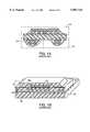
- FIG. 2Aillustrates, in a cross-sectional view, a ball grid array package including a multilayered structure for supporting a die in accordance with the invention.
- FIG. 2Billustrates, in an enlarged cut-away perspective view a portion of the structure of FIG. 2A in box 2B.
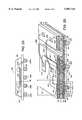
- FIGS. 3A-3Iillustrate, in cross-sectional views, a process for forming a structure in one embodiment of the invention.
- FIG. 3Jillustrates a variation of the process illustrated in FIGS. 3A-3I.
- FIGS. 4A-4Dillustrate, in cross-sectional views, another process for forming a structure in accordance with the invention.
- FIGS. 5A-5Dillustrate, in cross-sectional views, yet another process for forming a structure in accordance with the invention.
- FIGs. 6A-6Cillustrate, in cross-sectional views, still another process for forming a structure in accordance with the invention.
- FIGS. 7A-7Dillustrate, in cross-sectional views, still another process for forming a structure in accordance with the invention.
- FIGS. 8A-8Billustrate in a cross-sectional view and an enlarged view, respectively, similar to FIGS. 2A-2B, a die attached by conductive balls to the multilayered structure.
- a multilayered structure for supporting one or more electronic componentsincludes a support layer formed of a conductive material, such as a sheet of copper, that is thicker than any other layer in the structure.
- the support layerhas a number of conductive islands separated from other portions of the support layer by isolation gaps that are annular in shape.
- a ring of dielectric materialalso called “isolation ring” is located in each of the isolation gaps.
- Other layers of the multilayered structureare formed around and supported by the support layer.
- an integrated circuit package 200includes a structure 201 on which is mounted an integrated circuit die (also called "IC die") 202.
- IC die 202is attached to structure 201 by a die attach adhesive 203, and a number of bond wires 204A-204N (where N is the number of bond wires) electrically couple pads 202A-202N (FIG. 2B) to contacts 201A-201N of structure 201.
- a number of bond wires 204A-204Nwhere N is the number of bond wires electrically couple pads 202A-202N (FIG. 2B) to contacts 201A-201N of structure 201.
- FIGS. 2A-2BFor clarity, not all parts, e.g. pads 202A-202N, bond wires 204A-204N and contacts 201A-201N are shown in FIGS. 2A-2B.
- IC package 200also includes an encapsulant 208 formed on side 207 of structure 201, to thereby enclose IC die 202, bond wires 204A-204N and contacts 201A-201N.
- Structure 201is a multilayered structure that includes support layer 210 formed of a conductive material, such as a sheet of copper. Support layer 210 is sandwiched between dielectric layers 220 and 230 which in turn are sandwiched between conductive layers 240 and 250. Support layer 210 has a number of annular isolation gaps 211A, 211B . . . and a corresponding number of conductive islands 212A, 212B . . . surrounded by isolation gaps 211A-P, 211B . . . Conductive islands 212A, 212B . . . have a dimension Die.(e.g.
- isolation rings 213A, 213B . . .are formed between islands 212A, 212B . . . and portion 215 when a dielectric material is placed in isolation gaps 211A, 211B . . .
- support layer 210also includes another portion 216 on which is mounted IC die 202, and portion 216 is coupled to a source (not shown) of ground reference voltage, to thereby allow portion 216 to function as a ground reference plane.
- portion 216functions as a heat sink to absorb the heat generated by IC die 202.
- Portion 216passes the heat to conductive elements, e.g. element 232I, that then pass the heat to the substrate balls, e.g. ball 205I.
- portions 215 and 216 of support layer 210are separated from each other by a channel 217, thereby to allow portion 215 to be used as, for example, a power reference plane.
- support layer 210is sandwiched between compound layers 220 and 230 that are formed on the two sides 219A and 219B respectively of support layer 210.
- Each of compound layers 220 and 230includes respectively dielectric layers 221 and 231 in which are formed a number of via holes 221A, 221B . . . and via holes 231A, 231B . . . 231I.
- Compound layers 220 and 230also include a number of conductive elements 222A, 222B . . . and 232A, 232B . . . 232I located in the respective via holes 221A, 221B . . . and 231A, 231B . . . 231I.
- Structure 201also includes conductive layers 240 and 250 that are formed on compound layers 220 and 230 and etched to form contacts 201A, 201B . . . and 251A-251I respectively.
- Contacts 201A, 201B . . .are suitable for coupling to pads 202A, 202B of IC die 202, while contacts 251A-251I are suitable for coupling to substrate balls 205A-205I.
- tracese.g. traces 241A, 241B, are also formed on compound layers 220 and 230.
- Structure 201also includes protective layers formed of, for example, a solder mask material, such as layer 260 on portions of conductive layer 250 and compound layer 230, to thereby protect structure 201.
- each of isolation gaps 211A, 211B . . .has a height equal to thickness Ts of support layer 210, thereby to physically isolate each of islands 212A-212N from portion 215 of layer 210.
- each isolation gaphas an inner diameter Dhi of, e.g. 14 milli-inches, that is smaller than an outer diameter Dho of e.g. 16 milli-inches.
- an optional channel 217 of a height equal to sheet thickness Tsis also formed, thereby to isolate portion 215 from another portion 216 of layer 210.
- support layer 210is thicker than any other layer in multilayered structure 201 and thereby provides structural support to all other layers built around support layer 210.
- Use of etching as described below to form support layer 210eliminates the need for drilling holes and the associated costs and time needed to form a prior art IC package using a BT core layer.
- Structure 201 described above in reference to FIGS. 2A-2Bcan be formed by a number of processes.
- a support layeris formed from a sheet 311 of conductive material, e.g. copper.
- Sheet 311has a thickness Ts in the range of, for example, 3-20 milli-inches, preferably 5 milli-inches.
- Sheet 311can be of a large size sufficient to form a large number of IC package substrates simultaneously, which ball grid array substrates are obtained by dividing, e.g. by etching or routing at the end of the process (prior to mounting IC die).
- a sheet 311 of area 18 inches by 24 inchescan be processed as described below in reference to FIGS.
- FIGS. 3A-3Hare derived by adding 100, 200, . . . 600 to reference numerals in FIGS. 2A-2B that identify similar features.
- a compound layer 330is formed on a side 319B of sheet 311 (FIG. 3A) followed by formation of a conductive layer 350 on compound layer 330 (FIG. 3B).
- an adhesive layer(such as an oxide layer not shown) can be formed on side 319B of conductive sheet 311 followed by formation of a layer 331 of dielectric material for example by screen printing.
- a rough surfacecan be formed by e.g. etching or grinding, to improve adhesion of the applied dielectric material.
- the dielectric material used to form dielectric layer 331 in two alternative variations of this embodimentis nonphotoimageable or photoimageable.
- a number of via holese.g. via holes 331A-331M, are formed in dielectric layer 331 during the screen printing step.
- the photoimageable dielectric materialcan be screen printed or spray coated followed by imaging and developing the dielectric material to form via holes 331A-331M.
- conductive elements 332A-332Mcan be formed by filling via holes 331A-331M with a material, such as a conductive paste of the type described briefly below and in detail in U.S. patent application Ser. No. 08/538,886, filed Oct. 4, 1995, that was incorporated by reference above.
- a conductive pastecontains a binding material that is heavily loaded with conductive particles, for example, particles 333A-333S (FIG. 3C) in binding material 334 such that each of particles 333A-333S is in physical contact with one or more of particles 333A-333S so as to form a conductive element 332A through binding material 334.
- a conductive layer 350(FIG. 3D) is formed on compound layer 330, for example by lamination.
- sheet 311is etched to form a number of islands 312A, 312B . . . by printing and etching annular regions 313A, 313B . . . surrounding the to-be-formed islands 312A, 312B . . . thereby to form isolation gaps 311A, 311B . . .
- islands 312A, 312B . . .each have a smaller diameter D is (FIG. 3E) of, e.g. 4 milli-inches, and a larger diameter Dil of e.g. 6 milli-inches, due to isotropic etching.
- a dielectric materialis filled in various isolation gaps, e.g. isolation gap 311A (FIG. 3F) to form an isolation ring 313A surrounding island 312A. If a portion 391A (FIG. 3f) of the dielectric material protrudes outside of side 319A, the protruding portion can be polished off in another optional step.
- compound layer 320(FIG. 3G) is formed in a manner similar to that described above for compound layer 330.
- the dielectric material of dielectric layer 321 included in compound layer 320is removed from a region 326 over portion 316, thereby to expose a surface 316A of portion 316 (FIG. 3H).
- a conductive layer 340is formed. Conductive layers 340 and 350 are etched to form a group of traces 341A, 341B . . . and a second group of traces 351A, 351B . . . Traces 341A, 341B . . . are coupled to the respective conductive elements 322A, 322B . . .
- conductive traces 351A-351Iare coupled to conductive elements 332A-332I. Islands 312A, 312B . . . are in contact with conductive elements 322A, 322B . . . and 332A, 332B . . . Therefore, traces 341A, 341B . . . are coupled to traces 351A, 351B. Moreover, portions of support layer 310, such as portions 315 and 316 are in contact with certain of the conductive elements, e.g. portion 316 contacts conductive element 332I (FIG. 3G). Then, a solder mask material is applied to form layers 360 and 370 (FIG.
- a portion 316can be used as a reference plane for, for example, a ground reference voltage.
- portion 315can be used as a reference plane for, for example, a power reference voltage signal.
- portions 315 and 316can be electrically coupled to each other to form a single reference plane.
- conductive layers 340 and 350are formed by lamination
- conductive layers 340 and 350are formed by plating.
- the conductive material used in the plating stepis also plated into via holes 331A, 331B . . . in a manner well known in the art, as described in U.S. Pat. No. 5,097,593.
- a second compound layer 320 and a second conductive layer 340are not formed. Instead, bond wires, e.g.
- wire 304Aare directly attached to conductive islands, e.g. island 312B, as illustrated in FIG. 3J, after application of a Ni/Au layer on island 312B.
- islandsare formed approximately as solid cylinders, e.g. by jet etching.
- layers 330, 350, 320 and 340are formed sequentially as described above in reference to FIGS. 3A-3H, such layers can be formed simultaneously.
- compound layers 420 and 430(FIG. 4A) are formed simultaneously on the two sides 419A and 419B, respectively, of sheet 411.
- dielectric layers 421 and 431are formed on the respective sides 419A and 419B simultaneously, for example, by use of a photoimageable dielectric material.
- via holes 421A, 421B . . . and 431A, 431B . . .are formed in the respective dielectric layers 420 and 430, by imaging and developing.
- a number of annular openings 471A, 471B . . .are formed in dielectric layer 430 at locations adjacent to the to-be-formed isolation gaps in sheet 411.
- Via holes 421A, 421B . . . and 431A, 431B . . . in respective dielectric layers 421 and 431are filled with a conductive paste (described above) to form conductive elements 422A, 422B . . . and 432A, . . . respectively.
- conductive layers 440 and 450are formed on compound layers 420 and 430 respectively, for example, by lamination.
- traces 441A, 441B . . . and 451A, 451B . . .are defined in conductive layers 440 and 450, for example, by etching.
- conductive layers 440 and 450are also etched in annular areas 472A, 472B . . . that cover annular openings 471A, 471B . . . thereby to expose annular openings 471A, 471B . . . . If thickness Ts (FIG.
- isolation gaps 411A, 411B . . .can be formed (e.g. by etching) during the trace definition step. If such a process is used, traces 441A, 441B . . . and 451A, 451B . . . are protected with a coating, e.g. Ni/Au or Sn or solder prior to etching to form isolation gaps 411A, 411B . . .
- thickness Td of compound layers 421 and 431is about 2 milli-inches, which is also smaller than thickness Ts of support layer 410.
- conductive layers 440 and 450are protected, for example, by application of a resist material (not shown) after formation of traces 441A, 441B . . . and 451A, 451B . . ., and then sheet 411 is etched through annular gaps 471A, 471B . . . to thereby form isolation gaps 411A, 411B . . . .
- solder mask layers 460 and 480are formed on a compound layer 420 and conductive layer 440 on one side and on compound layer 430 and conductive layer 450 on the other side, thereby to form structure 401 (FIG. 4D).
- conductive balls 405A, 405B . . .e.g. formed of solder
- a dienot shown
- conductive elementsare formed by plating of via holes in a dielectric layer, as described below in reference to FIGS. 5A-5D.
- a dielectric materialis used to form a dielectric layer 531 on side 519A of sheet 511 (FIG. 5A).
- Dielectric layer 531has a number of via holes 531A-531I, that are formed by imaging and developing a photoimageable material used to form layer 531.
- Each of via holes 531A-531Ihas a diameter Dv of, for example, 6 milli-inches which is larger than twice the thickness Tc (e.g.
- conductive layer 550is formed on dielectric layer 531, for example, by plating.
- via holes 531A-531I of dielectric layer 531are plated such that a number of conductive elements 532A-532I are formed in via holes 531A-531I.
- Conductive elements 532A-532Iare formed in contact with the side 519B of sheet 511.
- sheet 511is etched on side 519A, in annular regions 572A-572I, thereby to form isolation gaps 511A-511I (FIG. 5B) surrounding islands 512A-512I, in a manner similar to that described above for FIG. 3D.
- a dielectric layer 521(FIG. 5C) is formed on side 519A on support layer 510.
- isolation gaps 511A-511Ican be filled to form isolation rings 513A-5131 around respective conductive islands 512A-512I.
- a number of via holes 521A-521Iare formed in dielectric layer 521, for example, by stencil printing, or alternatively by imaging and developing a photoimageable dielectric material used to form layer 521.
- a conductive layer 540is formed on dielectric layer 521, such that via holes 521A-521I are plated, to form conductive elements 522A-522I.
- conductive elements 522A-522I and 532A-532Iare illustrated in FIGS. 5A-5D as having a cup shape, such conductive elements can have other shapes (e.g. solid cylinder).
- conductive layers 540 and 550are etched to form traces 541A, 541B . . . and 551A, 551B
- protective layers 560 and 580are formed, for example, by applying a solder mask material to thereby complete formation of structure 501.
- solder balls 505A-505Iare formed on the respective traces of structure 501, to complete formation of a ball grid array package.
- a removable substrate 690such as a sheet of nickel is used to form a support layer of the invention.
- a dielectric materialis screen printed (or spray coated) on a first side 690A of removable substrate 690 at predetermined locations, thereby to form annular isolation rings, e.g. rings 613A, 613B . . .
- a photoimageable dielectric materialcan be applied all over removable substrate 690. After imaging and developing, dielectric material remains as isolation rings 613A, 613B . . . at the predetermined locations. Thereafter, a conductive material is plated on removable substrate 690 at all regions that are free of dielectric material, i.e.
- isolation rings 613A, 613B . . .e.g. portion 615 and islands 612A, 612B
- support layer 610FIG. 6B
- removable substrate 690is removed, e.g. peeled off (FIG. 6C).
- two compound layersare formed on the two sides 610A and 610B, and a conductive layer is formed on each of the compound layers in a manner similar to the steps discussed above, for example in reference to FIGS. 3A-3D.
- Adhesion between plated material 611 and isolation rings 613A, 613B . . .can be improved by either a curing step after support layer 610 is formed, or by an adhesion improving step, for example by increasing roughness of isolation rings 613A, 613B . . . before the plating step.
- a sheet 711 (FIG. 7A) of conductive materialis etched at predetermined locations 701A and 701B to form through holes 711A and 711B (FIG. 7B).
- Through holes 711A and 711Beach have a diameter Dt1 that is at least a multiple of thickness Ts of sheet 711.
- Dt1is 8 mils
- Tsis 2 mils.
- a dielectric materialis applied, for example by a spray coater, on the surfaces of holes 711A and 711B as well as on the sides 719A and 719B of sheet 711.
- Such application of dielectric materialforms dielectric layers 720, 730 (FIG. 7C) and a number of reel shaped dielectric elements 791A, 791B . . . around holes 711A, 711B . . .
- Each of dielectric layers 720 and 730has a thickness Td that is smaller than diameter Dt1 such that even after application of the dielectric material, through holes 790A, 790B . . . remain in dielectric elements 791A, 791B . . . Through holes 790A, 790B . .
- Dielectric layers 720 and 730also have a number of via holes 720A-720I and 730A-730I that are formed, for example by imaging and developing or, alternatively, during a screen printing step.
- a number of conductive elementsare formed in through holes 790A, 790B . . . , for example by filling with a conductive paste to form solid cylindrical conductive elements 712A, 712B . . . (FIG. 7D).
- via holes 720A-720I and 730A-730Iare also filled with the conductive paste to form e.g. thermal vias.
- conductive layers 740 and 750are formed on the compound layers 720 and 730 followed by etching to form traces, e.g. traces 741A, 741B, 751A and 751B.
- the conductive elementse.g. elements 712A and 712B, are insulated from portions of sheet 711 by reel shaped dielectric elements 791A, 791B . . .
- die 802(FIGS. 8A, 8B) is attached to multilayer substrate 801 by a number of conductive balls (also called die attach balls) 804A, 804B . . . 804N.
- a number of pads 802A-802N of die 802are coupled by the respective die attach balls 804A-804N to contacts 801A-801N of multilayered structure 801.
- Multilayered structure 801has a number of traces of the type similar to traces 241A and 241B (FIG. 2B) and also has other parts similar to those discussed above in reference to structure 201.
- a structure of three conductive layershas been described above, two such structures can be laminated to each other to form a structure of six conductive layers.
- a third compound layer(not shown) can be formed. Then two such structures can be laminated, with the third compound layers of the two structures facing each other, to form a single six layered structure.
Landscapes
- Engineering & Computer Science (AREA)
- Microelectronics & Electronic Packaging (AREA)
- Physics & Mathematics (AREA)
- Condensed Matter Physics & Semiconductors (AREA)
- General Physics & Mathematics (AREA)
- Computer Hardware Design (AREA)
- Power Engineering (AREA)
- Manufacturing & Machinery (AREA)
- Ceramic Engineering (AREA)
- Production Of Multi-Layered Print Wiring Board (AREA)
- Internal Circuitry In Semiconductor Integrated Circuit Devices (AREA)
Abstract
Description
Claims (8)
Priority Applications (1)
| Application Number | Priority Date | Filing Date | Title |
|---|---|---|---|
| US08/888,348US5987744A (en) | 1996-04-10 | 1997-07-01 | Method for supporting one or more electronic components |
Applications Claiming Priority (2)
| Application Number | Priority Date | Filing Date | Title |
|---|---|---|---|
| US08/631,875US5872338A (en) | 1996-04-10 | 1996-04-10 | Multilayer board having insulating isolation rings |
| US08/888,348US5987744A (en) | 1996-04-10 | 1997-07-01 | Method for supporting one or more electronic components |
Related Parent Applications (1)
| Application Number | Title | Priority Date | Filing Date |
|---|---|---|---|
| US08/631,875DivisionUS5872338A (en) | 1996-04-10 | 1996-04-10 | Multilayer board having insulating isolation rings |
Publications (1)
| Publication Number | Publication Date |
|---|---|
| US5987744Atrue US5987744A (en) | 1999-11-23 |
Family
ID=24533138
Family Applications (2)
| Application Number | Title | Priority Date | Filing Date |
|---|---|---|---|
| US08/631,875Expired - Fee RelatedUS5872338A (en) | 1996-04-10 | 1996-04-10 | Multilayer board having insulating isolation rings |
| US08/888,348Expired - Fee RelatedUS5987744A (en) | 1996-04-10 | 1997-07-01 | Method for supporting one or more electronic components |
Family Applications Before (1)
| Application Number | Title | Priority Date | Filing Date |
|---|---|---|---|
| US08/631,875Expired - Fee RelatedUS5872338A (en) | 1996-04-10 | 1996-04-10 | Multilayer board having insulating isolation rings |
Country Status (4)
| Country | Link |
|---|---|
| US (2) | US5872338A (en) |
| AU (1) | AU2433597A (en) |
| TW (1) | TW353859B (en) |
| WO (1) | WO1997038563A1 (en) |
Cited By (25)
| Publication number | Priority date | Publication date | Assignee | Title |
|---|---|---|---|---|
| US6169664B1 (en)* | 1998-01-05 | 2001-01-02 | Texas Instruments Incorporated | Selective performance enhancements for interconnect conducting paths |
| US6181569B1 (en)* | 1999-06-07 | 2001-01-30 | Kishore K. Chakravorty | Low cost chip size package and method of fabricating the same |
| US6285067B1 (en)* | 1999-04-26 | 2001-09-04 | Sanyo Electric Co., Ltd. | Electronic device and method for manufacturing the same |
| US20020027022A1 (en)* | 2000-07-27 | 2002-03-07 | Fujitsu Limited | Front-and-back electrically conductive substrate and method for manufacturing same |
| US6534391B1 (en)* | 2001-08-17 | 2003-03-18 | Amkor Technology, Inc. | Semiconductor package having substrate with laser-formed aperture through solder mask layer |
| US6660559B1 (en) | 2001-06-25 | 2003-12-09 | Amkor Technology, Inc. | Method of making a chip carrier package using laser ablation |
| WO2004097896A3 (en)* | 2003-04-26 | 2005-05-06 | Freescale Semiconductor Inc | A packaged integrated circuit having a heat spreader and method therefor |
| US20050230821A1 (en)* | 2004-04-15 | 2005-10-20 | Kheng Lee T | Semiconductor packages, and methods of forming semiconductor packages |
| US7180171B1 (en) | 2004-01-08 | 2007-02-20 | Smart Modular Technologies, Inc. | Single IC packaging solution for multi chip modules |
| US20080079776A1 (en)* | 2006-09-28 | 2008-04-03 | Frank Edward Anderson | Micro-Fluid Ejection Heads with Chips in Pockets |
| US20080111233A1 (en)* | 2006-11-10 | 2008-05-15 | Pendse Rajendra D | Semiconductor package with embedded die |
| US20080251279A1 (en)* | 2006-11-30 | 2008-10-16 | Shinko Electric Industries Co., Ltd. | Wiring board and method of manufacturing the same |
| US20090008140A1 (en)* | 2007-07-05 | 2009-01-08 | Occam Portfolio Llc | Electronic Assemblies Without Solder and Methods for their Manufacture |
| US20090103274A1 (en)* | 2005-06-24 | 2009-04-23 | Nxp B.V. | Warpage preventing substrates and method of making same |
| US20090114435A1 (en)* | 2007-01-18 | 2009-05-07 | Fujitsu Limited | Electronic device and method of manufacturing same |
| US20090261466A1 (en)* | 2006-11-10 | 2009-10-22 | Stats Chippac, Ltd. | Semiconductor Device and Method of Forming Vertical Interconnect Structure Using Stud Bumps |
| US20100148360A1 (en)* | 2008-12-12 | 2010-06-17 | Stats Chippac, Ltd. | Semiconductor Device and Method of Forming a Vertical Interconnect Structure for 3-D FO-WLCSP |
| US20100208436A1 (en)* | 2007-09-19 | 2010-08-19 | Dieter Cremer | Multilayer Circuit Board and Use of a Multilayer Circuit Board |
| US8592992B2 (en) | 2011-12-14 | 2013-11-26 | Stats Chippac, Ltd. | Semiconductor device and method of forming vertical interconnect structure with conductive micro via array for 3-D Fo-WLCSP |
| US9064936B2 (en) | 2008-12-12 | 2015-06-23 | Stats Chippac, Ltd. | Semiconductor device and method of forming a vertical interconnect structure for 3-D FO-WLCSP |
| US9082806B2 (en) | 2008-12-12 | 2015-07-14 | Stats Chippac, Ltd. | Semiconductor device and method of forming a vertical interconnect structure for 3-D FO-WLCSP |
| US9293401B2 (en) | 2008-12-12 | 2016-03-22 | Stats Chippac, Ltd. | Semiconductor device and method for forming a low profile embedded wafer level ball grid array molded laser package (EWLP-MLP) |
| US9640504B2 (en) | 2009-03-17 | 2017-05-02 | STATS ChipPAC Pte. Ltd. | Semiconductor device and method of providing z-interconnect conductive pillars with inner polymer core |
| US20170170098A1 (en)* | 2015-12-10 | 2017-06-15 | Intel Corporation | Flex circuit for accessing pins of a chip carrier |
| WO2020038503A1 (en)* | 2018-08-22 | 2020-02-27 | Gentherm Gmbh | Circuit module consisting of a plurality of components interconnected in an electrically conductive manner and method for producing a circuit module of this kind |
Families Citing this family (68)
| Publication number | Priority date | Publication date | Assignee | Title |
|---|---|---|---|---|
| US6962829B2 (en)* | 1996-10-31 | 2005-11-08 | Amkor Technology, Inc. | Method of making near chip size integrated circuit package |
| JPH1167809A (en)* | 1997-08-26 | 1999-03-09 | Sanyo Electric Co Ltd | Semiconductor device |
| US6346842B1 (en)* | 1997-12-12 | 2002-02-12 | Intel Corporation | Variable delay path circuit |
| JPH11307689A (en)* | 1998-02-17 | 1999-11-05 | Seiko Epson Corp | Semiconductor device, substrate for semiconductor device, manufacturing method thereof, and electronic equipment |
| SG75841A1 (en)* | 1998-05-02 | 2000-10-24 | Eriston Invest Pte Ltd | Flip chip assembly with via interconnection |
| US6603079B2 (en)* | 1999-02-05 | 2003-08-05 | Mack Technologies Florida, Inc. | Printed circuit board electrical interconnects |
| US6411718B1 (en) | 1999-04-28 | 2002-06-25 | Sound Physics Labs, Inc. | Sound reproduction employing unity summation aperture loudspeakers |
| TW512467B (en)* | 1999-10-12 | 2002-12-01 | North Kk | Wiring circuit substrate and manufacturing method therefor |
| US6356452B1 (en)* | 1999-10-13 | 2002-03-12 | Micron Technology, Inc. | Soldermask opening to prevent delamination |
| JP2001217279A (en)* | 2000-02-01 | 2001-08-10 | Mitsubishi Electric Corp | High density mounting equipment |
| US7061084B2 (en)* | 2000-02-29 | 2006-06-13 | Advanced Semiconductor Engineering, Inc. | Lead-bond type chip package and manufacturing method thereof |
| JP2001308226A (en) | 2000-04-24 | 2001-11-02 | Nec Corp | Semiconductor device |
| US6916683B2 (en)* | 2000-05-11 | 2005-07-12 | Micron Technology, Inc. | Methods of fabricating a molded ball grid array |
| US6400574B1 (en) | 2000-05-11 | 2002-06-04 | Micron Technology, Inc. | Molded ball grid array |
| US7262082B1 (en) | 2000-10-13 | 2007-08-28 | Bridge Semiconductor Corporation | Method of making a three-dimensional stacked semiconductor package with a metal pillar and a conductive interconnect in an encapsulant aperture |
| US6908788B1 (en) | 2000-10-13 | 2005-06-21 | Bridge Semiconductor Corporation | Method of connecting a conductive trace to a semiconductor chip using a metal base |
| US6876072B1 (en) | 2000-10-13 | 2005-04-05 | Bridge Semiconductor Corporation | Semiconductor chip assembly with chip in substrate cavity |
| US7075186B1 (en) | 2000-10-13 | 2006-07-11 | Bridge Semiconductor Corporation | Semiconductor chip assembly with interlocked contact terminal |
| US6949408B1 (en) | 2000-10-13 | 2005-09-27 | Bridge Semiconductor Corporation | Method of connecting a conductive trace and an insulative base to a semiconductor chip using multiple etch steps |
| US7319265B1 (en) | 2000-10-13 | 2008-01-15 | Bridge Semiconductor Corporation | Semiconductor chip assembly with precision-formed metal pillar |
| US7129575B1 (en) | 2000-10-13 | 2006-10-31 | Bridge Semiconductor Corporation | Semiconductor chip assembly with bumped metal pillar |
| US7129113B1 (en) | 2000-10-13 | 2006-10-31 | Bridge Semiconductor Corporation | Method of making a three-dimensional stacked semiconductor package with a metal pillar in an encapsulant aperture |
| US7264991B1 (en) | 2000-10-13 | 2007-09-04 | Bridge Semiconductor Corporation | Method of connecting a conductive trace to a semiconductor chip using conductive adhesive |
| US6984576B1 (en) | 2000-10-13 | 2006-01-10 | Bridge Semiconductor Corporation | Method of connecting an additively and subtractively formed conductive trace and an insulative base to a semiconductor chip |
| US7190080B1 (en) | 2000-10-13 | 2007-03-13 | Bridge Semiconductor Corporation | Semiconductor chip assembly with embedded metal pillar |
| US7132741B1 (en) | 2000-10-13 | 2006-11-07 | Bridge Semiconductor Corporation | Semiconductor chip assembly with carved bumped terminal |
| US7414319B2 (en) | 2000-10-13 | 2008-08-19 | Bridge Semiconductor Corporation | Semiconductor chip assembly with metal containment wall and solder terminal |
| US7071089B1 (en) | 2000-10-13 | 2006-07-04 | Bridge Semiconductor Corporation | Method of making a semiconductor chip assembly with a carved bumped terminal |
| US7009297B1 (en) | 2000-10-13 | 2006-03-07 | Bridge Semiconductor Corporation | Semiconductor chip assembly with embedded metal particle |
| US7094676B1 (en) | 2000-10-13 | 2006-08-22 | Bridge Semiconductor Corporation | Semiconductor chip assembly with embedded metal pillar |
| US6872591B1 (en) | 2000-10-13 | 2005-03-29 | Bridge Semiconductor Corporation | Method of making a semiconductor chip assembly with a conductive trace and a substrate |
| US6801438B1 (en)* | 2000-10-24 | 2004-10-05 | Touch Future Technolocy Ltd. | Electrical circuit and method of formation |
| US20040217472A1 (en)* | 2001-02-16 | 2004-11-04 | Integral Technologies, Inc. | Low cost chip carrier with integrated antenna, heat sink, or EMI shielding functions manufactured from conductive loaded resin-based materials |
| JP3418615B2 (en)* | 2001-06-12 | 2003-06-23 | 沖電気工業株式会社 | Semiconductor device and method of manufacturing the same |
| US20030059976A1 (en)* | 2001-09-24 | 2003-03-27 | Nathan Richard J. | Integrated package and methods for making same |
| US20030153119A1 (en)* | 2002-02-14 | 2003-08-14 | Nathan Richard J. | Integrated circuit package and method for fabrication |
| US7538415B1 (en) | 2003-11-20 | 2009-05-26 | Bridge Semiconductor Corporation | Semiconductor chip assembly with bumped terminal, filler and insulative base |
| US7425759B1 (en) | 2003-11-20 | 2008-09-16 | Bridge Semiconductor Corporation | Semiconductor chip assembly with bumped terminal and filler |
| JP4431747B2 (en)* | 2004-10-22 | 2010-03-17 | 富士通株式会社 | Manufacturing method of semiconductor device |
| US7268421B1 (en) | 2004-11-10 | 2007-09-11 | Bridge Semiconductor Corporation | Semiconductor chip assembly with welded metal pillar that includes enlarged ball bond |
| US7446419B1 (en) | 2004-11-10 | 2008-11-04 | Bridge Semiconductor Corporation | Semiconductor chip assembly with welded metal pillar of stacked metal balls |
| US7560813B2 (en) | 2005-06-14 | 2009-07-14 | John Trezza | Chip-based thermo-stack |
| US7687400B2 (en)* | 2005-06-14 | 2010-03-30 | John Trezza | Side stacking apparatus and method |
| US8456015B2 (en)* | 2005-06-14 | 2013-06-04 | Cufer Asset Ltd. L.L.C. | Triaxial through-chip connection |
| US7781886B2 (en)* | 2005-06-14 | 2010-08-24 | John Trezza | Electronic chip contact structure |
| US7851348B2 (en)* | 2005-06-14 | 2010-12-14 | Abhay Misra | Routingless chip architecture |
| US7989958B2 (en)* | 2005-06-14 | 2011-08-02 | Cufer Assett Ltd. L.L.C. | Patterned contact |
| US7838997B2 (en)* | 2005-06-14 | 2010-11-23 | John Trezza | Remote chip attachment |
| US7521806B2 (en)* | 2005-06-14 | 2009-04-21 | John Trezza | Chip spanning connection |
| US20060281303A1 (en)* | 2005-06-14 | 2006-12-14 | John Trezza | Tack & fuse chip bonding |
| US7534722B2 (en) | 2005-06-14 | 2009-05-19 | John Trezza | Back-to-front via process |
| US7786592B2 (en) | 2005-06-14 | 2010-08-31 | John Trezza | Chip capacitive coupling |
| US20060278996A1 (en)* | 2005-06-14 | 2006-12-14 | John Trezza | Active packaging |
| US7767493B2 (en)* | 2005-06-14 | 2010-08-03 | John Trezza | Post & penetration interconnection |
| KR100797698B1 (en)* | 2005-09-27 | 2008-01-23 | 삼성전기주식회사 | High density printed circuit board manufacturing method |
| US7687397B2 (en)* | 2006-06-06 | 2010-03-30 | John Trezza | Front-end processed wafer having through-chip connections |
| US20070281460A1 (en)* | 2006-06-06 | 2007-12-06 | Cubic Wafer, Inc. | Front-end processed wafer having through-chip connections |
| JP5269799B2 (en)* | 2006-10-17 | 2013-08-21 | キューファー アセット リミテッド. エル.エル.シー. | Wafer via formation |
| US7705613B2 (en)* | 2007-01-03 | 2010-04-27 | Abhay Misra | Sensitivity capacitive sensor |
| US7670874B2 (en)* | 2007-02-16 | 2010-03-02 | John Trezza | Plated pillar package formation |
| US7847404B1 (en) | 2007-03-29 | 2010-12-07 | Integrated Device Technology, Inc. | Circuit board assembly and packaged integrated circuit device with power and ground channels |
| US7850060B2 (en)* | 2007-04-05 | 2010-12-14 | John Trezza | Heat cycle-able connection |
| US7748116B2 (en)* | 2007-04-05 | 2010-07-06 | John Trezza | Mobile binding in an electronic connection |
| US7960210B2 (en)* | 2007-04-23 | 2011-06-14 | Cufer Asset Ltd. L.L.C. | Ultra-thin chip packaging |
| TWI351903B (en)* | 2007-07-25 | 2011-11-01 | Unimicron Technology Corp | A circuit board structure with concave conductive |
| US20120025930A1 (en)* | 2010-07-30 | 2012-02-02 | International Business Machines Corporation | Programmable antifuse matrix for module decoupling |
| US20160014878A1 (en)* | 2014-04-25 | 2016-01-14 | Rogers Corporation | Thermal management circuit materials, method of manufacture thereof, and articles formed therefrom |
| TWI594671B (en)* | 2014-12-17 | 2017-08-01 | Flexible circuit board micro-aperture conductive through-hole structure and manufacturing method |
Citations (183)
| Publication number | Priority date | Publication date | Assignee | Title |
|---|---|---|---|---|
| US3335327A (en)* | 1965-01-06 | 1967-08-08 | Augat Inc | Holder for attaching flat pack to printed circuit board |
| US3384879A (en)* | 1964-03-13 | 1968-05-21 | Bbc Brown Boveri & Cie | Diode-matrix device for data storing and translating purposes |
| US3615913A (en)* | 1968-11-08 | 1971-10-26 | Westinghouse Electric Corp | Polyimide and polyamide-polyimide as a semiconductor surface passivator and protectant coating |
| US3808576A (en)* | 1971-01-15 | 1974-04-30 | Mica Corp | Circuit board with resistance layer |
| US3857683A (en)* | 1973-07-27 | 1974-12-31 | Mica Corp | Printed circuit board material incorporating binary alloys |
| US3923359A (en)* | 1971-07-09 | 1975-12-02 | Pressey Handel Und Investments | Multi-layer printed-circuit boards |
| US4024629A (en)* | 1974-12-31 | 1977-05-24 | International Business Machines Corporation | Fabrication techniques for multilayer ceramic modules |
| US4090667A (en)* | 1977-05-13 | 1978-05-23 | Aries Electronics, Inc. | Universally programmable shorting plug for an integrated circuit socket |
| US4146863A (en)* | 1976-03-11 | 1979-03-27 | Siemens Aktiengesellschaft | One-piece fusible conductor for low-voltage fuses |
| US4238839A (en)* | 1979-04-19 | 1980-12-09 | National Semiconductor Corporation | Laser programmable read only memory |
| US4245273A (en)* | 1979-06-29 | 1981-01-13 | International Business Machines Corporation | Package for mounting and interconnecting a plurality of large scale integrated semiconductor devices |
| US4247981A (en)* | 1979-06-18 | 1981-02-03 | Western Electric Company, Inc. | Methods of assembling interconnect members with printed circuit boards |
| US4386051A (en)* | 1980-09-19 | 1983-05-31 | Edgington Robert E | Tin, lead, zinc alloy |
| US4399372A (en)* | 1979-12-14 | 1983-08-16 | Nippon Telegraph And Telephone Public Corporation | Integrated circuit having spare parts activated by a high-to-low adjustable resistance device |
| US4413272A (en)* | 1979-09-05 | 1983-11-01 | Fujitsu Limited | Semiconductor devices having fuses |
| US4420820A (en)* | 1980-12-29 | 1983-12-13 | Signetics Corporation | Programmable read-only memory |
| US4424578A (en)* | 1980-07-14 | 1984-01-03 | Tokyo Shibaura Denki Kabushiki Kaisha | Bipolar prom |
| US4433331A (en)* | 1981-12-14 | 1984-02-21 | Bell Telephone Laboratories, Incorporated | Programmable logic array interconnection matrix |
| US4434134A (en)* | 1981-04-10 | 1984-02-28 | International Business Machines Corporation | Pinned ceramic substrate |
| US4455495A (en)* | 1979-10-01 | 1984-06-19 | Hitachi, Ltd. | Programmable semiconductor integrated circuitry including a programming semiconductor element |
| US4458297A (en)* | 1981-01-16 | 1984-07-03 | Mosaic Systems, Inc. | Universal interconnection substrate |
| US4488262A (en)* | 1981-06-25 | 1984-12-11 | International Business Machines Corporation | Electronically programmable read only memory |
| US4491860A (en)* | 1982-04-23 | 1985-01-01 | Signetics Corporation | TiW2 N Fusible links in semiconductor integrated circuits |
| US4507756A (en)* | 1982-03-23 | 1985-03-26 | Texas Instruments Incorporated | Avalanche fuse element as programmable device |
| US4507757A (en)* | 1982-03-23 | 1985-03-26 | Texas Instruments Incorporated | Avalanche fuse element in programmable memory |
| US4547830A (en)* | 1979-09-11 | 1985-10-15 | Rohm Company Limited | Device for protection of a semiconductor device |
| US4562639A (en)* | 1982-03-23 | 1986-01-07 | Texas Instruments Incorporated | Process for making avalanche fuse element with isolated emitter |
| US4565712A (en)* | 1980-04-24 | 1986-01-21 | Tokyo Shibaura Denki Kabushiki Kaisha | Method of making a semiconductor read only memory |
| US4566186A (en)* | 1984-06-29 | 1986-01-28 | Tektronix, Inc. | Multilayer interconnect circuitry using photoimageable dielectric |
| US4569120A (en)* | 1983-03-07 | 1986-02-11 | Signetics Corporation | Method of fabricating a programmable read-only memory cell incorporating an antifuse utilizing ion implantation |
| US4569121A (en)* | 1983-03-07 | 1986-02-11 | Signetics Corporation | Method of fabricating a programmable read-only memory cell incorporating an antifuse utilizing deposition of amorphous semiconductor layer |
| US4585490A (en)* | 1981-12-07 | 1986-04-29 | Massachusetts Institute Of Technology | Method of making a conductive path in multi-layer metal structures by low power laser beam |
| US4590589A (en)* | 1982-12-21 | 1986-05-20 | Zoran Corporation | Electrically programmable read only memory |
| US4609241A (en)* | 1984-05-25 | 1986-09-02 | 4C Electronics, Inc. | Programmable programmed socket |
| US4642160A (en)* | 1985-08-12 | 1987-02-10 | Interconnect Technology Inc. | Multilayer circuit board manufacturing |
| US4652974A (en)* | 1985-10-28 | 1987-03-24 | International Business Machines Corporation | Method and structure for effecting engineering changes in a multiple device module package |
| US4651409A (en)* | 1984-02-09 | 1987-03-24 | Ncr Corporation | Method of fabricating a high density, low power, merged vertical fuse/bipolar transistor |
| US4678889A (en)* | 1984-11-06 | 1987-07-07 | Nec Corporation | Method of laser trimming in semiconductor wafer |
| US4689411A (en)* | 1981-04-10 | 1987-08-25 | Otsuka Kagaku Yakuhin Kabushiki Kaisha | 4-thio azetidinone intermediates and process for the preparation of the same |
| US4700116A (en)* | 1985-03-29 | 1987-10-13 | Hitachi, Ltd. | System for controlling brushless DC motor |
| US4700214A (en)* | 1983-12-15 | 1987-10-13 | Laserpath Corporation | Electrical circuitry |
| US4710592A (en)* | 1985-06-25 | 1987-12-01 | Nec Corporation | Multilayer wiring substrate with engineering change pads |
| US4721868A (en)* | 1986-09-23 | 1988-01-26 | Advanced Micro Devices, Inc. | IC input circuitry programmable for realizing multiple functions from a single input |
| US4726991A (en)* | 1986-07-10 | 1988-02-23 | Eos Technologies Inc. | Electrical overstress protection material and process |
| US4731704A (en)* | 1984-09-03 | 1988-03-15 | Siemens Aktiengesellschaft | Arrangement for modifying electrical printed circuit boards |
| US4732780A (en)* | 1985-09-26 | 1988-03-22 | General Electric Company | Method of making hermetic feedthrough in ceramic substrate |
| US4748490A (en)* | 1985-08-01 | 1988-05-31 | Texas Instruments Incorporated | Deep polysilicon emitter antifuse memory cell |
| US4757359A (en)* | 1986-04-07 | 1988-07-12 | American Microsystems, Inc. | Thin oxide fuse |
| US4780670A (en)* | 1985-03-04 | 1988-10-25 | Xerox Corporation | Active probe card for high resolution/low noise wafer level testing |
| US4786904A (en)* | 1986-12-15 | 1988-11-22 | Zoran Corporation | Electronically programmable gate array having programmable interconnect lines |
| US4789760A (en)* | 1985-04-30 | 1988-12-06 | Advanced Micro Devices, Inc. | Via in a planarized dielectric and process for producing same |
| US4791075A (en)* | 1987-10-05 | 1988-12-13 | Motorola, Inc. | Process for making a hermetic low cost pin grid array package |
| US4792646A (en)* | 1985-04-03 | 1988-12-20 | Ibiden Kabushiki Kaisha | Ceramic wiring board and its production |
| US4792835A (en)* | 1986-12-05 | 1988-12-20 | Texas Instruments Incorporated | MOS programmable memories using a metal fuse link and process for making the same |
| US4796074A (en)* | 1987-04-27 | 1989-01-03 | Instant Circuit Corporation | Method of fabricating a high density masked programmable read-only memory |
| US4796075A (en)* | 1983-12-21 | 1989-01-03 | Advanced Micro Devices, Inc. | Fusible link structure for integrated circuits |
| US4799128A (en)* | 1985-12-20 | 1989-01-17 | Ncr Corporation | Multilayer printed circuit board with domain partitioning |
| US4799984A (en)* | 1987-09-18 | 1989-01-24 | E. I. Du Pont De Nemours And Company | Method for fabricating multilayer circuits |
| US4803595A (en)* | 1986-11-17 | 1989-02-07 | International Business Machines Corporation | Interposer chip technique for making engineering changes between interconnected semiconductor chips |
| US4808967A (en)* | 1985-05-29 | 1989-02-28 | Ohmega Electronics | Circuit board material |
| US4821142A (en)* | 1986-06-06 | 1989-04-11 | Hitachi, Ltd. | Ceramic multilayer circuit board and semiconductor module |
| US4823181A (en)* | 1986-05-09 | 1989-04-18 | Actel Corporation | Programmable low impedance anti-fuse element |
| US4829404A (en)* | 1987-04-27 | 1989-05-09 | Flexmark, Inc. | Method of producing a flexible circuit and master grid therefor |
| US4839864A (en)* | 1987-03-09 | 1989-06-13 | Mitsubishi Denki Kabushiki Kaisha | Semiconductor memory device comprising programmable redundancy circuit |
| US4841099A (en)* | 1988-05-02 | 1989-06-20 | Xerox Corporation | Electrically insulating polymer matrix with conductive path formed in situ |
| US4840924A (en)* | 1984-07-11 | 1989-06-20 | Nec Corporation | Method of fabricating a multichip package |
| US4845315A (en)* | 1984-05-02 | 1989-07-04 | Mosaic Systems | Cable system |
| US4847732A (en)* | 1983-09-15 | 1989-07-11 | Mosaic Systems, Inc. | Wafer and method of making same |
| US4864165A (en)* | 1985-03-22 | 1989-09-05 | Advanced Micro Devices, Inc. | ECL programmable logic array with direct testing means for verification of programmed state |
| US4873506A (en)* | 1988-03-09 | 1989-10-10 | Cooper Industries, Inc. | Metallo-organic film fractional ampere fuses and method of making |
| US4874711A (en)* | 1987-05-26 | 1989-10-17 | Georgia Tech Research Corporation | Method for altering characteristics of active semiconductor devices |
| US4876220A (en)* | 1986-05-16 | 1989-10-24 | Actel Corporation | Method of making programmable low impedance interconnect diode element |
| US4881114A (en)* | 1986-05-16 | 1989-11-14 | Actel Corporation | Selectively formable vertical diode circuit element |
| US4882611A (en)* | 1988-07-21 | 1989-11-21 | Zoran Corporation | Double layer voltage-programmable device and method of manufacturing same |
| US4888574A (en)* | 1985-05-29 | 1989-12-19 | 501 Ohmega Electronics, Inc. | Circuit board material and method of making |
| US4888665A (en)* | 1988-02-19 | 1989-12-19 | Microelectronics And Computer Technology Corporation | Customizable circuitry |
| US4892776A (en)* | 1987-09-02 | 1990-01-09 | Ohmega Electronics, Inc. | Circuit board material and electroplating bath for the production thereof |
| US4893167A (en)* | 1986-07-11 | 1990-01-09 | Pull S.A. | Method for programmable laser connection of two superimposed conductors of the interconnect system of an integrated circuit |
| US4897836A (en)* | 1987-10-20 | 1990-01-30 | Gazelle Microcircuits, Inc. | Programmable connection path circuit |
| US4899205A (en)* | 1986-05-09 | 1990-02-06 | Actel Corporation | Electrically-programmable low-impedance anti-fuse element |
| US4910418A (en)* | 1988-12-29 | 1990-03-20 | Gazelle Microcircuits, Inc. | Semiconductor fuse programmable array structure |
| US4910584A (en)* | 1981-10-30 | 1990-03-20 | Fujitsu Limited | Semiconductor device |
| US4914055A (en)* | 1989-08-24 | 1990-04-03 | Advanced Micro Devices, Inc. | Semiconductor antifuse structure and method |
| US4915983A (en)* | 1985-06-10 | 1990-04-10 | The Foxboro Company | Multilayer circuit board fabrication process |
| US4920454A (en)* | 1983-09-15 | 1990-04-24 | Mosaic Systems, Inc. | Wafer scale package system and header and method of manufacture thereof |
| US4924287A (en)* | 1985-01-20 | 1990-05-08 | Avner Pdahtzur | Personalizable CMOS gate array device and technique |
| US4933738A (en)* | 1988-04-25 | 1990-06-12 | Elron Electronic Industries, Ltd. | Customizable semiconductor devices |
| US4935584A (en)* | 1988-05-24 | 1990-06-19 | Tektronix, Inc. | Method of fabricating a printed circuit board and the PCB produced |
| US4937475A (en)* | 1988-09-19 | 1990-06-26 | Massachusetts Institute Of Technology | Laser programmable integrated circuit |
| US4940181A (en)* | 1989-04-06 | 1990-07-10 | Motorola, Inc. | Pad grid array for receiving a solder bumped chip carrier |
| US4943538A (en)* | 1986-05-09 | 1990-07-24 | Actel Corporation | Programmable low impedance anti-fuse element |
| US4949084A (en)* | 1985-10-29 | 1990-08-14 | Ohio Associated Enterprises, Inc. | Programmable integrated crosspoint switch |
| US4964948A (en)* | 1985-04-16 | 1990-10-23 | Protocad, Inc. | Printed circuit board through hole technique |
| US4969124A (en)* | 1989-03-07 | 1990-11-06 | National Semiconductor Corporation | Method for vertical fuse testing |
| US4970579A (en)* | 1988-09-21 | 1990-11-13 | International Business Machines Corp. | Integrated circuit package with improved cooling means |
| US4974048A (en)* | 1989-03-10 | 1990-11-27 | The Boeing Company | Integrated circuit having reroutable conductive paths |
| US4977357A (en)* | 1988-01-11 | 1990-12-11 | Shrier Karen P | Overvoltage protection device and material |
| US4992333A (en)* | 1988-11-18 | 1991-02-12 | G&H Technology, Inc. | Electrical overstress pulse protection |
| US5003486A (en)* | 1989-02-24 | 1991-03-26 | Nero Technologies Ltd. | Programmable safety electrical socket controller |
| US5014002A (en) | 1989-04-18 | 1991-05-07 | Vlsi Technology, Inc. | ATE jumper programmable interface board |
| US5027191A (en) | 1989-05-11 | 1991-06-25 | Westinghouse Electric Corp. | Cavity-down chip carrier with pad grid array |
| US5030113A (en) | 1990-11-05 | 1991-07-09 | Itt Corporation | One-piece insulator body and flexible circuit |
| US5055321A (en) | 1988-04-28 | 1991-10-08 | Ibiden Co., Ltd. | Adhesive for electroless plating, printed circuit boards and method of producing the same |
| US5055973A (en) | 1990-01-17 | 1991-10-08 | Aptix Corporation | Custom tooled printed circuit board |
| US5060116A (en) | 1990-04-20 | 1991-10-22 | Grobman Warren D | Electronics system with direct write engineering change capability |
| US5068634A (en) | 1988-01-11 | 1991-11-26 | Electromer Corporation | Overvoltage protection device and material |
| US5077451A (en) | 1990-01-17 | 1991-12-31 | Aptix Corporation | Custom tooled printed circuit board |
| US5087589A (en) | 1987-06-12 | 1992-02-11 | Massachusetts Institute Of Technology | Selectively programmable interconnections in multilayer integrated circuits |
| US5092032A (en) | 1990-05-28 | 1992-03-03 | International Business Machines Corp. | Manufacturing method for a multilayer printed circuit board |
| US5099149A (en) | 1990-12-19 | 1992-03-24 | At&T Bell Laboratories | Programmable integrated circuit |
| US5099380A (en) | 1990-04-19 | 1992-03-24 | Electromer Corporation | Electrical connector with overvoltage protection feature |
| US5097593A (en) | 1988-12-16 | 1992-03-24 | International Business Machines Corporation | Method of forming a hybrid printed circuit board |
| US5106773A (en) | 1990-10-09 | 1992-04-21 | Texas Instruments Incorporated | Programmable gate array and methods for its fabrication |
| US5108541A (en) | 1991-03-06 | 1992-04-28 | International Business Machines Corp. | Processes for electrically conductive decals filled with inorganic insulator material |
| US5120679A (en) | 1991-06-04 | 1992-06-09 | Vlsi Technology, Inc. | Anti-fuse structures and methods for making same |
| US5136366A (en) | 1990-11-05 | 1992-08-04 | Motorola, Inc. | Overmolded semiconductor package with anchoring means |
| US5142263A (en) | 1991-02-13 | 1992-08-25 | Electromer Corporation | Surface mount device with overvoltage protection feature |
| US5144567A (en) | 1988-02-26 | 1992-09-01 | Preh-Werke Gmbh & Co. Kg | Programmable plug and cable for computer keyboards |
| US5148355A (en) | 1988-12-24 | 1992-09-15 | Technology Applications Company Limited | Method for making printed circuits |
| US5148265A (en) | 1990-09-24 | 1992-09-15 | Ist Associates, Inc. | Semiconductor chip assemblies with fan-in leads |
| US5155577A (en) | 1991-01-07 | 1992-10-13 | International Business Machines Corporation | Integrated circuit carriers and a method for making engineering changes in said carriers |
| US5159535A (en) | 1987-03-11 | 1992-10-27 | International Business Machines Corporation | Method and apparatus for mounting a flexible film semiconductor chip carrier on a circuitized substrate |
| US5166556A (en) | 1991-01-22 | 1992-11-24 | Myson Technology, Inc. | Programmable antifuse structure, process, logic cell and architecture for programmable integrated circuits |
| US5170931A (en) | 1987-03-11 | 1992-12-15 | International Business Machines Corporation | Method and apparatus for mounting a flexible film semiconductor chip carrier on a circuitized substrate |
| US5181096A (en) | 1990-04-12 | 1993-01-19 | Actel Corporation | Electrically programmable antifuse incorporating dielectric and amorphous silicon interlayer |
| US5181859A (en) | 1991-04-29 | 1993-01-26 | Trw Inc. | Electrical connector circuit wafer |
| US5189387A (en) | 1991-07-11 | 1993-02-23 | Electromer Corporation | Surface mount device with foldback switching overvoltage protection feature |
| US5191511A (en) | 1991-02-08 | 1993-03-02 | Kabushiki Kaisha Toshiba | Semiconductor device including a package having a plurality of bumps arranged in a grid form as external terminals |
| US5196724A (en) | 1991-04-26 | 1993-03-23 | Quicklogic Corporation | Programmable interconnect structures and programmable integrated circuits |
| US5200652A (en) | 1991-11-13 | 1993-04-06 | Micron Technology, Inc. | Programmable/reprogrammable structure combining both antifuse and fuse elements |
| US5203075A (en) | 1991-08-12 | 1993-04-20 | Inernational Business Machines | Method of bonding flexible circuit to cicuitized substrate to provide electrical connection therebetween using different solders |
| US5210940A (en) | 1990-07-24 | 1993-05-18 | Nippon Cmk Corp. | Method of producing a printed circuit board |
| US5216278A (en) | 1990-12-04 | 1993-06-01 | Motorola, Inc. | Semiconductor device having a pad array carrier package |
| US5218679A (en) | 1990-03-01 | 1993-06-08 | Fuji Electric Co., Ltd. | Programmable controller with input/output signal converting circuit for variably setting a number of inputs and/or outputs |
| US5220490A (en) | 1990-10-25 | 1993-06-15 | Microelectronics And Computer Technology Corporation | Substrate interconnect allowing personalization using spot surface links |
| US5229549A (en) | 1989-11-13 | 1993-07-20 | Sumitomo Electric Industries, Ltd. | Ceramic circuit board and a method of manufacturing the ceramic circuit board |
| US5233217A (en) | 1991-05-03 | 1993-08-03 | Crosspoint Solutions | Plug contact with antifuse |
| US5231751A (en) | 1991-10-29 | 1993-08-03 | International Business Machines Corporation | Process for thin film interconnect |
| US5248517A (en) | 1991-11-15 | 1993-09-28 | Electromer Corporation | Paintable/coatable overvoltage protection material and devices made therefrom |
| US5250470A (en) | 1989-12-22 | 1993-10-05 | Oki Electric Industry Co., Ltd. | Method for manufacturing a semiconductor device with corrosion resistant leads |
| US5250228A (en) | 1991-11-06 | 1993-10-05 | Raychem Corporation | Conductive polymer composition |
| US5258643A (en) | 1991-07-25 | 1993-11-02 | Massachusetts Institute Of Technology | Electrically programmable link structures and methods of making same |
| US5260848A (en) | 1990-07-27 | 1993-11-09 | Electromer Corporation | Foldback switching material and devices |
| US5260519A (en) | 1992-09-23 | 1993-11-09 | International Business Machines Corporation | Multilayer ceramic substrate with graded vias |
| US5262754A (en) | 1992-09-23 | 1993-11-16 | Electromer Corporation | Overvoltage protection element |
| US5262352A (en) | 1992-08-31 | 1993-11-16 | Motorola, Inc. | Method for forming an interconnection structure for conductive layers |
| US5264729A (en) | 1992-07-29 | 1993-11-23 | Lsi Logic Corporation | Semiconductor package having programmable interconnect |
| US5282271A (en) | 1991-10-30 | 1994-01-25 | I-Cube Design Systems, Inc. | I/O buffering system to a programmable switching apparatus |
| US5282312A (en) | 1991-12-31 | 1994-02-01 | Tessera, Inc. | Multi-layer circuit construction methods with customization features |
| US5287620A (en) | 1991-06-18 | 1994-02-22 | Fujitsu Limited | Process of producing multiple-layer glass-ceramic circuit board |
| US5291062A (en) | 1993-03-01 | 1994-03-01 | Motorola, Inc. | Area array semiconductor device having a lid with functional contacts |
| US5294750A (en) | 1990-09-18 | 1994-03-15 | Ngk Insulators, Ltd. | Ceramic packages and ceramic wiring board |
| US5300208A (en) | 1989-08-14 | 1994-04-05 | International Business Machines Corporation | Fabrication of printed circuit boards using conducting polymer |
| US5311053A (en) | 1991-06-12 | 1994-05-10 | Aptix Corporation | Interconnection network |
| US5317801A (en) | 1990-04-23 | 1994-06-07 | Nippon Mektron, Ltd. | Method of manufacture of multilayer circuit board |
| US5321322A (en) | 1991-11-27 | 1994-06-14 | Aptix Corporation | Programmable interconnect architecture without active devices |
| US5329153A (en) | 1992-04-10 | 1994-07-12 | Crosspoint Solutions, Inc. | Antifuse with nonstoichiometric tin layer and method of manufacture thereof |
| US5345106A (en) | 1990-06-01 | 1994-09-06 | Robert Bosch Gmbh | Electronic circuit component with heat sink mounted on a lead frame |
| US5347258A (en) | 1993-04-07 | 1994-09-13 | Zycon Corporation | Annular resistor coupled with printed circuit board through-hole |
| US5349248A (en) | 1992-09-03 | 1994-09-20 | Xilinx, Inc. | Adaptive programming method for antifuse technology |
| US5367764A (en) | 1991-12-31 | 1994-11-29 | Tessera, Inc. | Method of making a multi-layer circuit assembly |
| US5377124A (en) | 1989-09-20 | 1994-12-27 | Aptix Corporation | Field programmable printed circuit board |
| EP0336359B1 (en) | 1988-04-04 | 1995-01-25 | Hitachi, Ltd. | Semiconductor package |
| US5397921A (en) | 1993-09-03 | 1995-03-14 | Advanced Semiconductor Assembly Technology | Tab grid array |
| US5404637A (en) | 1992-05-01 | 1995-04-11 | Nippon Cmk Corp. | Method of manufacturing multilayer printed wiring board |
| US5410806A (en) | 1993-09-15 | 1995-05-02 | Lsi Logic Corporation | Method for fabricating conductive epoxy grid array semiconductors packages |
| US5420456A (en) | 1992-04-02 | 1995-05-30 | International Business Machines Corporation | ZAG fuse for reduced blow-current application |
| US5420460A (en) | 1993-08-05 | 1995-05-30 | Vlsi Technology, Inc. | Thin cavity down ball grid array package based on wirebond technology |
| US5421083A (en) | 1994-04-01 | 1995-06-06 | Motorola, Inc. | Method of manufacturing a circuit carrying substrate having coaxial via holes |
| US5435480A (en) | 1993-12-23 | 1995-07-25 | International Business Machines Corporation | Method for filling plated through holes |
| US5436412A (en) | 1992-10-30 | 1995-07-25 | International Business Machines Corporation | Interconnect structure having improved metallization |
| US5438166A (en) | 1987-09-29 | 1995-08-01 | Microelectronics And Computer Technology Corporation | Customizable circuitry |
| US5464790A (en) | 1992-09-23 | 1995-11-07 | Actel Corporation | Method of fabricating an antifuse element having an etch-stop dielectric layer |
| US5468995A (en) | 1994-07-05 | 1995-11-21 | Motorola, Inc. | Semiconductor device having compliant columnar electrical connections |
| US5481795A (en) | 1992-05-06 | 1996-01-09 | Matsushita Electric Industrial Co., Ltd. | Method of manufacturing organic substrate used for printed circuits |
| US5487218A (en) | 1994-11-21 | 1996-01-30 | International Business Machines Corporation | Method for making printed circuit boards with selectivity filled plated through holes |
| US5502889A (en) | 1988-06-10 | 1996-04-02 | Sheldahl, Inc. | Method for electrically and mechanically connecting at least two conductive layers |
| US5537108A (en) | 1994-02-08 | 1996-07-16 | Prolinx Labs Corporation | Method and structure for programming fuses |
| US5572409A (en) | 1994-02-08 | 1996-11-05 | Prolinx Labs Corporation | Apparatus including a programmable socket adapter for coupling an electronic component to a component socket on a printed circuit board |
| US5574311A (en) | 1994-01-28 | 1996-11-12 | Fujitsu Limited | Device having pins formed of hardened mixture of conductive metal particle and resin |
| US5583378A (en) | 1994-05-16 | 1996-12-10 | Amkor Electronics, Inc. | Ball grid array integrated circuit package with thermal conductor |
| US5583376A (en) | 1995-01-03 | 1996-12-10 | Motorola, Inc. | High performance semiconductor device with resin substrate and method for making the same |
| US5612574A (en) | 1995-06-06 | 1997-03-18 | Texas Instruments Incorporated | Semiconductor structures using high-dielectric-constant materials and an adhesion layer |
Family Cites Families (1)
| Publication number | Priority date | Publication date | Assignee | Title |
|---|---|---|---|---|
| US4689441A (en)* | 1985-04-05 | 1987-08-25 | International Business Machines Corporation | Routing method and pattern for reducing cross talk noise problems on printed interconnection boards |
- 1996
- 1996-04-10USUS08/631,875patent/US5872338A/ennot_activeExpired - Fee Related
- 1996-06-03TWTW085106623Apatent/TW353859B/enactive
- 1997
- 1997-04-10AUAU24335/97Apatent/AU2433597A/ennot_activeAbandoned
- 1997-04-10WOPCT/US1997/005430patent/WO1997038563A1/enactiveApplication Filing
- 1997-07-01USUS08/888,348patent/US5987744A/ennot_activeExpired - Fee Related
Patent Citations (189)
| Publication number | Priority date | Publication date | Assignee | Title |
|---|---|---|---|---|
| US3384879A (en)* | 1964-03-13 | 1968-05-21 | Bbc Brown Boveri & Cie | Diode-matrix device for data storing and translating purposes |
| US3335327A (en)* | 1965-01-06 | 1967-08-08 | Augat Inc | Holder for attaching flat pack to printed circuit board |
| US3615913A (en)* | 1968-11-08 | 1971-10-26 | Westinghouse Electric Corp | Polyimide and polyamide-polyimide as a semiconductor surface passivator and protectant coating |
| US3808576A (en)* | 1971-01-15 | 1974-04-30 | Mica Corp | Circuit board with resistance layer |
| US3923359A (en)* | 1971-07-09 | 1975-12-02 | Pressey Handel Und Investments | Multi-layer printed-circuit boards |
| US3857683A (en)* | 1973-07-27 | 1974-12-31 | Mica Corp | Printed circuit board material incorporating binary alloys |
| US4024629A (en)* | 1974-12-31 | 1977-05-24 | International Business Machines Corporation | Fabrication techniques for multilayer ceramic modules |
| US4146863A (en)* | 1976-03-11 | 1979-03-27 | Siemens Aktiengesellschaft | One-piece fusible conductor for low-voltage fuses |
| US4090667A (en)* | 1977-05-13 | 1978-05-23 | Aries Electronics, Inc. | Universally programmable shorting plug for an integrated circuit socket |
| US4238839A (en)* | 1979-04-19 | 1980-12-09 | National Semiconductor Corporation | Laser programmable read only memory |
| US4247981A (en)* | 1979-06-18 | 1981-02-03 | Western Electric Company, Inc. | Methods of assembling interconnect members with printed circuit boards |
| US4245273A (en)* | 1979-06-29 | 1981-01-13 | International Business Machines Corporation | Package for mounting and interconnecting a plurality of large scale integrated semiconductor devices |
| US4413272A (en)* | 1979-09-05 | 1983-11-01 | Fujitsu Limited | Semiconductor devices having fuses |
| US4547830A (en)* | 1979-09-11 | 1985-10-15 | Rohm Company Limited | Device for protection of a semiconductor device |
| US4455495A (en)* | 1979-10-01 | 1984-06-19 | Hitachi, Ltd. | Programmable semiconductor integrated circuitry including a programming semiconductor element |
| US4399372A (en)* | 1979-12-14 | 1983-08-16 | Nippon Telegraph And Telephone Public Corporation | Integrated circuit having spare parts activated by a high-to-low adjustable resistance device |
| US4565712A (en)* | 1980-04-24 | 1986-01-21 | Tokyo Shibaura Denki Kabushiki Kaisha | Method of making a semiconductor read only memory |
| US4424578A (en)* | 1980-07-14 | 1984-01-03 | Tokyo Shibaura Denki Kabushiki Kaisha | Bipolar prom |
| US4386051A (en)* | 1980-09-19 | 1983-05-31 | Edgington Robert E | Tin, lead, zinc alloy |
| US4420820A (en)* | 1980-12-29 | 1983-12-13 | Signetics Corporation | Programmable read-only memory |
| US4458297A (en)* | 1981-01-16 | 1984-07-03 | Mosaic Systems, Inc. | Universal interconnection substrate |
| US4689411A (en)* | 1981-04-10 | 1987-08-25 | Otsuka Kagaku Yakuhin Kabushiki Kaisha | 4-thio azetidinone intermediates and process for the preparation of the same |
| US4434134A (en)* | 1981-04-10 | 1984-02-28 | International Business Machines Corporation | Pinned ceramic substrate |
| US4488262A (en)* | 1981-06-25 | 1984-12-11 | International Business Machines Corporation | Electronically programmable read only memory |
| US4910584A (en)* | 1981-10-30 | 1990-03-20 | Fujitsu Limited | Semiconductor device |
| US4585490A (en)* | 1981-12-07 | 1986-04-29 | Massachusetts Institute Of Technology | Method of making a conductive path in multi-layer metal structures by low power laser beam |
| US4433331A (en)* | 1981-12-14 | 1984-02-21 | Bell Telephone Laboratories, Incorporated | Programmable logic array interconnection matrix |
| US4507757A (en)* | 1982-03-23 | 1985-03-26 | Texas Instruments Incorporated | Avalanche fuse element in programmable memory |
| US4507756A (en)* | 1982-03-23 | 1985-03-26 | Texas Instruments Incorporated | Avalanche fuse element as programmable device |
| US4562639A (en)* | 1982-03-23 | 1986-01-07 | Texas Instruments Incorporated | Process for making avalanche fuse element with isolated emitter |
| US4491860A (en)* | 1982-04-23 | 1985-01-01 | Signetics Corporation | TiW2 N Fusible links in semiconductor integrated circuits |
| US4590589A (en)* | 1982-12-21 | 1986-05-20 | Zoran Corporation | Electrically programmable read only memory |
| US4569121A (en)* | 1983-03-07 | 1986-02-11 | Signetics Corporation | Method of fabricating a programmable read-only memory cell incorporating an antifuse utilizing deposition of amorphous semiconductor layer |
| US4569120A (en)* | 1983-03-07 | 1986-02-11 | Signetics Corporation | Method of fabricating a programmable read-only memory cell incorporating an antifuse utilizing ion implantation |
| US4920454A (en)* | 1983-09-15 | 1990-04-24 | Mosaic Systems, Inc. | Wafer scale package system and header and method of manufacture thereof |
| US4847732A (en)* | 1983-09-15 | 1989-07-11 | Mosaic Systems, Inc. | Wafer and method of making same |
| US4700214A (en)* | 1983-12-15 | 1987-10-13 | Laserpath Corporation | Electrical circuitry |
| US4796075A (en)* | 1983-12-21 | 1989-01-03 | Advanced Micro Devices, Inc. | Fusible link structure for integrated circuits |
| US4651409A (en)* | 1984-02-09 | 1987-03-24 | Ncr Corporation | Method of fabricating a high density, low power, merged vertical fuse/bipolar transistor |
| US4845315A (en)* | 1984-05-02 | 1989-07-04 | Mosaic Systems | Cable system |
| US4609241A (en)* | 1984-05-25 | 1986-09-02 | 4C Electronics, Inc. | Programmable programmed socket |
| US4566186A (en)* | 1984-06-29 | 1986-01-28 | Tektronix, Inc. | Multilayer interconnect circuitry using photoimageable dielectric |
| US4840924A (en)* | 1984-07-11 | 1989-06-20 | Nec Corporation | Method of fabricating a multichip package |
| US4731704A (en)* | 1984-09-03 | 1988-03-15 | Siemens Aktiengesellschaft | Arrangement for modifying electrical printed circuit boards |
| US4678889A (en)* | 1984-11-06 | 1987-07-07 | Nec Corporation | Method of laser trimming in semiconductor wafer |
| US4924287A (en)* | 1985-01-20 | 1990-05-08 | Avner Pdahtzur | Personalizable CMOS gate array device and technique |
| US4780670A (en)* | 1985-03-04 | 1988-10-25 | Xerox Corporation | Active probe card for high resolution/low noise wafer level testing |
| US4864165A (en)* | 1985-03-22 | 1989-09-05 | Advanced Micro Devices, Inc. | ECL programmable logic array with direct testing means for verification of programmed state |
| US4700116A (en)* | 1985-03-29 | 1987-10-13 | Hitachi, Ltd. | System for controlling brushless DC motor |
| US4792646A (en)* | 1985-04-03 | 1988-12-20 | Ibiden Kabushiki Kaisha | Ceramic wiring board and its production |
| US4964948A (en)* | 1985-04-16 | 1990-10-23 | Protocad, Inc. | Printed circuit board through hole technique |
| US4789760A (en)* | 1985-04-30 | 1988-12-06 | Advanced Micro Devices, Inc. | Via in a planarized dielectric and process for producing same |
| US4808967A (en)* | 1985-05-29 | 1989-02-28 | Ohmega Electronics | Circuit board material |
| US4888574A (en)* | 1985-05-29 | 1989-12-19 | 501 Ohmega Electronics, Inc. | Circuit board material and method of making |
| US4915983A (en)* | 1985-06-10 | 1990-04-10 | The Foxboro Company | Multilayer circuit board fabrication process |
| US4710592A (en)* | 1985-06-25 | 1987-12-01 | Nec Corporation | Multilayer wiring substrate with engineering change pads |
| US4748490A (en)* | 1985-08-01 | 1988-05-31 | Texas Instruments Incorporated | Deep polysilicon emitter antifuse memory cell |
| US4642160A (en)* | 1985-08-12 | 1987-02-10 | Interconnect Technology Inc. | Multilayer circuit board manufacturing |
| US4732780A (en)* | 1985-09-26 | 1988-03-22 | General Electric Company | Method of making hermetic feedthrough in ceramic substrate |
| US4652974A (en)* | 1985-10-28 | 1987-03-24 | International Business Machines Corporation | Method and structure for effecting engineering changes in a multiple device module package |
| US4949084A (en)* | 1985-10-29 | 1990-08-14 | Ohio Associated Enterprises, Inc. | Programmable integrated crosspoint switch |
| US4799128A (en)* | 1985-12-20 | 1989-01-17 | Ncr Corporation | Multilayer printed circuit board with domain partitioning |
| US4757359A (en)* | 1986-04-07 | 1988-07-12 | American Microsystems, Inc. | Thin oxide fuse |
| US4823181A (en)* | 1986-05-09 | 1989-04-18 | Actel Corporation | Programmable low impedance anti-fuse element |
| US4943538A (en)* | 1986-05-09 | 1990-07-24 | Actel Corporation | Programmable low impedance anti-fuse element |
| US4899205A (en)* | 1986-05-09 | 1990-02-06 | Actel Corporation | Electrically-programmable low-impedance anti-fuse element |
| US4876220A (en)* | 1986-05-16 | 1989-10-24 | Actel Corporation | Method of making programmable low impedance interconnect diode element |
| US4881114A (en)* | 1986-05-16 | 1989-11-14 | Actel Corporation | Selectively formable vertical diode circuit element |
| US4821142A (en)* | 1986-06-06 | 1989-04-11 | Hitachi, Ltd. | Ceramic multilayer circuit board and semiconductor module |
| US4726991A (en)* | 1986-07-10 | 1988-02-23 | Eos Technologies Inc. | Electrical overstress protection material and process |
| US4916809A (en)* | 1986-07-11 | 1990-04-17 | Bull S.A. | Method for programmable laser connection of two superimposed conductors of the interconnect system of an integrated circuit |
| US4893167A (en)* | 1986-07-11 | 1990-01-09 | Pull S.A. | Method for programmable laser connection of two superimposed conductors of the interconnect system of an integrated circuit |
| US4721868A (en)* | 1986-09-23 | 1988-01-26 | Advanced Micro Devices, Inc. | IC input circuitry programmable for realizing multiple functions from a single input |
| US4803595A (en)* | 1986-11-17 | 1989-02-07 | International Business Machines Corporation | Interposer chip technique for making engineering changes between interconnected semiconductor chips |
| US4792835A (en)* | 1986-12-05 | 1988-12-20 | Texas Instruments Incorporated | MOS programmable memories using a metal fuse link and process for making the same |
| US4786904A (en)* | 1986-12-15 | 1988-11-22 | Zoran Corporation | Electronically programmable gate array having programmable interconnect lines |
| US4839864A (en)* | 1987-03-09 | 1989-06-13 | Mitsubishi Denki Kabushiki Kaisha | Semiconductor memory device comprising programmable redundancy circuit |
| US5170931A (en) | 1987-03-11 | 1992-12-15 | International Business Machines Corporation | Method and apparatus for mounting a flexible film semiconductor chip carrier on a circuitized substrate |
| US5159535A (en) | 1987-03-11 | 1992-10-27 | International Business Machines Corporation | Method and apparatus for mounting a flexible film semiconductor chip carrier on a circuitized substrate |
| US4796074A (en)* | 1987-04-27 | 1989-01-03 | Instant Circuit Corporation | Method of fabricating a high density masked programmable read-only memory |
| US4829404A (en)* | 1987-04-27 | 1989-05-09 | Flexmark, Inc. | Method of producing a flexible circuit and master grid therefor |
| US4874711A (en)* | 1987-05-26 | 1989-10-17 | Georgia Tech Research Corporation | Method for altering characteristics of active semiconductor devices |
| US5087589A (en) | 1987-06-12 | 1992-02-11 | Massachusetts Institute Of Technology | Selectively programmable interconnections in multilayer integrated circuits |
| US4892776A (en)* | 1987-09-02 | 1990-01-09 | Ohmega Electronics, Inc. | Circuit board material and electroplating bath for the production thereof |
| US4799984A (en)* | 1987-09-18 | 1989-01-24 | E. I. Du Pont De Nemours And Company | Method for fabricating multilayer circuits |
| US5438166A (en) | 1987-09-29 | 1995-08-01 | Microelectronics And Computer Technology Corporation | Customizable circuitry |
| US4791075A (en)* | 1987-10-05 | 1988-12-13 | Motorola, Inc. | Process for making a hermetic low cost pin grid array package |
| US4897836A (en)* | 1987-10-20 | 1990-01-30 | Gazelle Microcircuits, Inc. | Programmable connection path circuit |
| US4977357A (en)* | 1988-01-11 | 1990-12-11 | Shrier Karen P | Overvoltage protection device and material |
| US5068634A (en) | 1988-01-11 | 1991-11-26 | Electromer Corporation | Overvoltage protection device and material |
| US4888665A (en)* | 1988-02-19 | 1989-12-19 | Microelectronics And Computer Technology Corporation | Customizable circuitry |
| US5144567A (en) | 1988-02-26 | 1992-09-01 | Preh-Werke Gmbh & Co. Kg | Programmable plug and cable for computer keyboards |
| US4873506A (en)* | 1988-03-09 | 1989-10-10 | Cooper Industries, Inc. | Metallo-organic film fractional ampere fuses and method of making |
| EP0336359B1 (en) | 1988-04-04 | 1995-01-25 | Hitachi, Ltd. | Semiconductor package |
| US4933738A (en)* | 1988-04-25 | 1990-06-12 | Elron Electronic Industries, Ltd. | Customizable semiconductor devices |
| US5055321A (en) | 1988-04-28 | 1991-10-08 | Ibiden Co., Ltd. | Adhesive for electroless plating, printed circuit boards and method of producing the same |
| US4841099A (en)* | 1988-05-02 | 1989-06-20 | Xerox Corporation | Electrically insulating polymer matrix with conductive path formed in situ |
| US4935584A (en)* | 1988-05-24 | 1990-06-19 | Tektronix, Inc. | Method of fabricating a printed circuit board and the PCB produced |
| US5502889A (en) | 1988-06-10 | 1996-04-02 | Sheldahl, Inc. | Method for electrically and mechanically connecting at least two conductive layers |
| US4882611A (en)* | 1988-07-21 | 1989-11-21 | Zoran Corporation | Double layer voltage-programmable device and method of manufacturing same |
| US4937475B1 (en)* | 1988-09-19 | 1994-03-29 | Massachusetts Inst Technology | Laser programmable integrated circuit |
| US4937475A (en)* | 1988-09-19 | 1990-06-26 | Massachusetts Institute Of Technology | Laser programmable integrated circuit |
| US4970579A (en)* | 1988-09-21 | 1990-11-13 | International Business Machines Corp. | Integrated circuit package with improved cooling means |
| US4992333A (en)* | 1988-11-18 | 1991-02-12 | G&H Technology, Inc. | Electrical overstress pulse protection |
| US5097593A (en) | 1988-12-16 | 1992-03-24 | International Business Machines Corporation | Method of forming a hybrid printed circuit board |
| US5148355A (en) | 1988-12-24 | 1992-09-15 | Technology Applications Company Limited | Method for making printed circuits |
| US4910418A (en)* | 1988-12-29 | 1990-03-20 | Gazelle Microcircuits, Inc. | Semiconductor fuse programmable array structure |
| US5003486A (en)* | 1989-02-24 | 1991-03-26 | Nero Technologies Ltd. | Programmable safety electrical socket controller |
| US4969124A (en)* | 1989-03-07 | 1990-11-06 | National Semiconductor Corporation | Method for vertical fuse testing |
| US4974048A (en)* | 1989-03-10 | 1990-11-27 | The Boeing Company | Integrated circuit having reroutable conductive paths |
| US4940181A (en)* | 1989-04-06 | 1990-07-10 | Motorola, Inc. | Pad grid array for receiving a solder bumped chip carrier |
| US5014002A (en) | 1989-04-18 | 1991-05-07 | Vlsi Technology, Inc. | ATE jumper programmable interface board |
| US5027191A (en) | 1989-05-11 | 1991-06-25 | Westinghouse Electric Corp. | Cavity-down chip carrier with pad grid array |
| US5300208A (en) | 1989-08-14 | 1994-04-05 | International Business Machines Corporation | Fabrication of printed circuit boards using conducting polymer |
| US4914055A (en)* | 1989-08-24 | 1990-04-03 | Advanced Micro Devices, Inc. | Semiconductor antifuse structure and method |
| US5377124A (en) | 1989-09-20 | 1994-12-27 | Aptix Corporation | Field programmable printed circuit board |
| US5229549A (en) | 1989-11-13 | 1993-07-20 | Sumitomo Electric Industries, Ltd. | Ceramic circuit board and a method of manufacturing the ceramic circuit board |
| US5250470A (en) | 1989-12-22 | 1993-10-05 | Oki Electric Industry Co., Ltd. | Method for manufacturing a semiconductor device with corrosion resistant leads |
| US5077451A (en) | 1990-01-17 | 1991-12-31 | Aptix Corporation | Custom tooled printed circuit board |
| US5055973A (en) | 1990-01-17 | 1991-10-08 | Aptix Corporation | Custom tooled printed circuit board |
| US5218679A (en) | 1990-03-01 | 1993-06-08 | Fuji Electric Co., Ltd. | Programmable controller with input/output signal converting circuit for variably setting a number of inputs and/or outputs |
| US5181096A (en) | 1990-04-12 | 1993-01-19 | Actel Corporation | Electrically programmable antifuse incorporating dielectric and amorphous silicon interlayer |
| US5099380A (en) | 1990-04-19 | 1992-03-24 | Electromer Corporation | Electrical connector with overvoltage protection feature |
| US5060116A (en) | 1990-04-20 | 1991-10-22 | Grobman Warren D | Electronics system with direct write engineering change capability |
| US5317801A (en) | 1990-04-23 | 1994-06-07 | Nippon Mektron, Ltd. | Method of manufacture of multilayer circuit board |
| US5092032A (en) | 1990-05-28 | 1992-03-03 | International Business Machines Corp. | Manufacturing method for a multilayer printed circuit board |
| US5345106A (en) | 1990-06-01 | 1994-09-06 | Robert Bosch Gmbh | Electronic circuit component with heat sink mounted on a lead frame |
| US5210940A (en) | 1990-07-24 | 1993-05-18 | Nippon Cmk Corp. | Method of producing a printed circuit board |
| US5260848A (en) | 1990-07-27 | 1993-11-09 | Electromer Corporation | Foldback switching material and devices |
| US5294750A (en) | 1990-09-18 | 1994-03-15 | Ngk Insulators, Ltd. | Ceramic packages and ceramic wiring board |
| US5148265A (en) | 1990-09-24 | 1992-09-15 | Ist Associates, Inc. | Semiconductor chip assemblies with fan-in leads |
| US5106773A (en) | 1990-10-09 | 1992-04-21 | Texas Instruments Incorporated | Programmable gate array and methods for its fabrication |
| US5220490A (en) | 1990-10-25 | 1993-06-15 | Microelectronics And Computer Technology Corporation | Substrate interconnect allowing personalization using spot surface links |
| US5136366A (en) | 1990-11-05 | 1992-08-04 | Motorola, Inc. | Overmolded semiconductor package with anchoring means |
| US5030113A (en) | 1990-11-05 | 1991-07-09 | Itt Corporation | One-piece insulator body and flexible circuit |
| US5216278A (en) | 1990-12-04 | 1993-06-01 | Motorola, Inc. | Semiconductor device having a pad array carrier package |
| US5099149A (en) | 1990-12-19 | 1992-03-24 | At&T Bell Laboratories | Programmable integrated circuit |
| US5155577A (en) | 1991-01-07 | 1992-10-13 | International Business Machines Corporation | Integrated circuit carriers and a method for making engineering changes in said carriers |
| US5166556A (en) | 1991-01-22 | 1992-11-24 | Myson Technology, Inc. | Programmable antifuse structure, process, logic cell and architecture for programmable integrated circuits |
| US5191511A (en) | 1991-02-08 | 1993-03-02 | Kabushiki Kaisha Toshiba | Semiconductor device including a package having a plurality of bumps arranged in a grid form as external terminals |
| US5142263A (en) | 1991-02-13 | 1992-08-25 | Electromer Corporation | Surface mount device with overvoltage protection feature |
| US5108541A (en) | 1991-03-06 | 1992-04-28 | International Business Machines Corp. | Processes for electrically conductive decals filled with inorganic insulator material |
| US5196724A (en) | 1991-04-26 | 1993-03-23 | Quicklogic Corporation | Programmable interconnect structures and programmable integrated circuits |
| US5362676A (en) | 1991-04-26 | 1994-11-08 | Quicklogic Corporation | Programmable interconnect structures and programmable integrated circuits |
| US5319238A (en) | 1991-04-26 | 1994-06-07 | Quicklogic Corporation | Programmable interconnect structures and programmable integrated circuits |
| US5181859A (en) | 1991-04-29 | 1993-01-26 | Trw Inc. | Electrical connector circuit wafer |
| US5233217A (en) | 1991-05-03 | 1993-08-03 | Crosspoint Solutions | Plug contact with antifuse |
| US5120679A (en) | 1991-06-04 | 1992-06-09 | Vlsi Technology, Inc. | Anti-fuse structures and methods for making same |
| US5311053A (en) | 1991-06-12 | 1994-05-10 | Aptix Corporation | Interconnection network |
| US5287620A (en) | 1991-06-18 | 1994-02-22 | Fujitsu Limited | Process of producing multiple-layer glass-ceramic circuit board |
| US5189387A (en) | 1991-07-11 | 1993-02-23 | Electromer Corporation | Surface mount device with foldback switching overvoltage protection feature |
| US5258643A (en) | 1991-07-25 | 1993-11-02 | Massachusetts Institute Of Technology | Electrically programmable link structures and methods of making same |
| US5203075A (en) | 1991-08-12 | 1993-04-20 | Inernational Business Machines | Method of bonding flexible circuit to cicuitized substrate to provide electrical connection therebetween using different solders |
| US5231751A (en) | 1991-10-29 | 1993-08-03 | International Business Machines Corporation | Process for thin film interconnect |
| US5282271A (en) | 1991-10-30 | 1994-01-25 | I-Cube Design Systems, Inc. | I/O buffering system to a programmable switching apparatus |
| US5250228A (en) | 1991-11-06 | 1993-10-05 | Raychem Corporation | Conductive polymer composition |
| US5200652A (en) | 1991-11-13 | 1993-04-06 | Micron Technology, Inc. | Programmable/reprogrammable structure combining both antifuse and fuse elements |
| US5248517A (en) | 1991-11-15 | 1993-09-28 | Electromer Corporation | Paintable/coatable overvoltage protection material and devices made therefrom |
| US5321322A (en) | 1991-11-27 | 1994-06-14 | Aptix Corporation | Programmable interconnect architecture without active devices |
| US5282312A (en) | 1991-12-31 | 1994-02-01 | Tessera, Inc. | Multi-layer circuit construction methods with customization features |
| US5367764A (en) | 1991-12-31 | 1994-11-29 | Tessera, Inc. | Method of making a multi-layer circuit assembly |
| US5420456A (en) | 1992-04-02 | 1995-05-30 | International Business Machines Corporation | ZAG fuse for reduced blow-current application |
| US5329153A (en) | 1992-04-10 | 1994-07-12 | Crosspoint Solutions, Inc. | Antifuse with nonstoichiometric tin layer and method of manufacture thereof |
| US5404637A (en) | 1992-05-01 | 1995-04-11 | Nippon Cmk Corp. | Method of manufacturing multilayer printed wiring board |
| US5481795A (en) | 1992-05-06 | 1996-01-09 | Matsushita Electric Industrial Co., Ltd. | Method of manufacturing organic substrate used for printed circuits |
| US5264729A (en) | 1992-07-29 | 1993-11-23 | Lsi Logic Corporation | Semiconductor package having programmable interconnect |
| US5262352A (en) | 1992-08-31 | 1993-11-16 | Motorola, Inc. | Method for forming an interconnection structure for conductive layers |
| US5408130A (en) | 1992-08-31 | 1995-04-18 | Motorola, Inc. | Interconnection structure for conductive layers |
| US5349248A (en) | 1992-09-03 | 1994-09-20 | Xilinx, Inc. | Adaptive programming method for antifuse technology |
| US5464790A (en) | 1992-09-23 | 1995-11-07 | Actel Corporation | Method of fabricating an antifuse element having an etch-stop dielectric layer |
| US5262754A (en) | 1992-09-23 | 1993-11-16 | Electromer Corporation | Overvoltage protection element |
| US5260519A (en) | 1992-09-23 | 1993-11-09 | International Business Machines Corporation | Multilayer ceramic substrate with graded vias |
| US5436412A (en) | 1992-10-30 | 1995-07-25 | International Business Machines Corporation | Interconnect structure having improved metallization |
| US5291062A (en) | 1993-03-01 | 1994-03-01 | Motorola, Inc. | Area array semiconductor device having a lid with functional contacts |
| US5347258A (en) | 1993-04-07 | 1994-09-13 | Zycon Corporation | Annular resistor coupled with printed circuit board through-hole |
| US5420460A (en) | 1993-08-05 | 1995-05-30 | Vlsi Technology, Inc. | Thin cavity down ball grid array package based on wirebond technology |
| US5409865A (en) | 1993-09-03 | 1995-04-25 | Advanced Semiconductor Assembly Technology | Process for assembling a TAB grid array package for an integrated circuit |
| US5397921A (en) | 1993-09-03 | 1995-03-14 | Advanced Semiconductor Assembly Technology | Tab grid array |
| US5410806A (en) | 1993-09-15 | 1995-05-02 | Lsi Logic Corporation | Method for fabricating conductive epoxy grid array semiconductors packages |
| US5435480A (en) | 1993-12-23 | 1995-07-25 | International Business Machines Corporation | Method for filling plated through holes |
| US5574311A (en) | 1994-01-28 | 1996-11-12 | Fujitsu Limited | Device having pins formed of hardened mixture of conductive metal particle and resin |
| US5572409A (en) | 1994-02-08 | 1996-11-05 | Prolinx Labs Corporation | Apparatus including a programmable socket adapter for coupling an electronic component to a component socket on a printed circuit board |
| US5537108A (en) | 1994-02-08 | 1996-07-16 | Prolinx Labs Corporation | Method and structure for programming fuses |
| US5421083A (en) | 1994-04-01 | 1995-06-06 | Motorola, Inc. | Method of manufacturing a circuit carrying substrate having coaxial via holes |
| US5583378A (en) | 1994-05-16 | 1996-12-10 | Amkor Electronics, Inc. | Ball grid array integrated circuit package with thermal conductor |
| US5468995A (en) | 1994-07-05 | 1995-11-21 | Motorola, Inc. | Semiconductor device having compliant columnar electrical connections |
| US5487218A (en) | 1994-11-21 | 1996-01-30 | International Business Machines Corporation | Method for making printed circuit boards with selectivity filled plated through holes |
| US5583376A (en) | 1995-01-03 | 1996-12-10 | Motorola, Inc. | High performance semiconductor device with resin substrate and method for making the same |
| US5612574A (en) | 1995-06-06 | 1997-03-18 | Texas Instruments Incorporated | Semiconductor structures using high-dielectric-constant materials and an adhesion layer |
Non-Patent Citations (71)
| Title |
|---|
| "A Large Format Modified TEA CO2 Laser Based Process For Cost Effective Small Via Generation", J.M. Morrison etc., MCM 1994 Proceedings, pp. 369-377. |
| "A Laser Linking Process For Restructurable VLSI", G. H. Chapman, etc., CLEO, Apr., 1982, pp. 1-4. |
| "A New Circuit Substrate For MCM-L", Yusuke Wada etc., ICEMCM, 1995, pp. 59-64. |
| "A Novel MOS PROM Using a Highly Resistive Poly-Si Resistor", Masafumi Tanimoto etc., IEEE, 1980, 4 pages. |
| "Advanced Single Poly BiCMOS Technology For High Performance Programmable TTL/ECL Applications", Ali Iranmanesh etc., IEEE Bipolar Circuits and Technology Meeting, 1990, 4 pages. |
| "An Advancement in the Design and Application of Current-Limiting Fuses", R. Ranjan etc., General Electric Company, believed to be published prior to Apr. 10, 1996, pp. 36-40. |
| "An Enhanced Performance Low Cost BGA Package", Marrs, etc., Amkor Electronics, Inc., pp. 214-225. |
| "An Ultra High Speed ECL Programmable Logic Device", Fred Ki etc., IEEE Bipolar Circuits and Technology Meeting, 1990, 5 pages. |
| "Antifuse Structure Comparison For Field Programmable Gate Arrays", Steve Chiang etc., IEEE, 1992, pp. 611-614. |
| "Ball Grid Array Technology", John H. Lau, McGraw-Hill, Inc., 1995, p. 38. |
| "Characteriziang Quickturn ASICS: It's Done With Mirrors", Ron Iscoff, Semiconductor International, Aug. 1990, 6 pages. |
| "CMOS Resistive Fuse Circuits", Hae-Seung Lee etc., Dept. of Electrical Engineering and Computer Science, Massachusetts Institute of Technology, 1990, pp. 109-110. |
| "CMOS Resistive Fuses For Image Smoothing and Segmentation", Paul C. Yu etc., IEEE, 1992, pp. 545-553. |
| "Conducting Filament of the Programmed Metal Electrode Amorphose Silicon Antifuse", Kathryn E. Gordon etc., IEEE, 1993, pp. 27-30. |
| "Dielectric Based Antifuse For Logic and Memory ICs", Esmat Hamdy etc., IEEE 1988, pp. 786-789. |
| "Distribution Fuses of Nearest Future", T. Lipski, 3rd International Conference on Future Trends in Distribution Switch Gear, Jul. 26, 1990, pp. 41-45. |
| "High-Performance Scalable Switch Design", Joshua Silver, ASIC & EDA, Jun. 1994, pp. 38-48. |
| "I/O Buffering System to a Programmable Switching Apparatus", Wen-Jai Hsieh etc., Official Gazette, Jan. 25, 1994, one page. |
| "Interconnect Devices for Field Programmable Gate Array", Chenming Hu, IEEE, 1992, pp. 591-594. |
| "Interplay of Energies in Circuit Breaker and Fuse Combinations", Bernie DiMarco etc., IEEE, 1991, pp. 1765-1769. |
| "Laser Personalization of NMOS Digital Topologies", James B. Gullett etc., IEEE, 1983, pp. 1249-1252. |
| "Matsushita Team Eliminates Holes in High-Density PCB", Tsuda, Nikkei Electronics Asia, Mar. 1995 pp. 69-70. |
| "Polyswitch Resettable Fuses for Circuit Protection Information Package", Raychem Corporation, Electronics Division, Nov. 9, 1992. |
| "Printed Circuit Board Design Guidelines For Ball Grid Array Packages", Johnston, Motorola, Inc., pp. 255-260. |
| "Process Considerations In Restructurable VLSI For Wafer-Scale Integratin", P. W. Wyatt, etc., IEDM, 1984, pp. 626-629. |
| "Rigid-Flex" The Old and the New, Jahn Stopperan, Shendahl, Inc., 1990, 4 pages. |
| "TAIYO PSR-4000 Photoimageable Solder Mask (Two-Part Aqueous Developing System)", Taiyo America, Inc., Feb. 24, 1992, pp. 1-8. |
| "The Application of Laser Process Technology to Thin Film Packaging", T.F. Redmond etc., IEEE, 1992, pp. 1066-1071. |
| A Large Format Modified TEA CO 2 Laser Based Process For Cost Effective Small Via Generation , J.M. Morrison etc., MCM 1994 Proceedings, pp. 369 377.* |
| A Laser Linking Process For Restructurable VLSI , G. H. Chapman, etc., CLEO, Apr., 1982, pp. 1 4.* |
| A New Circuit Substrate For MCM L , Yusuke Wada etc., ICEMCM, 1995, pp. 59 64.* |
| A Novel MOS PROM Using a Highly Resistive Poly Si Resistor , Masafumi Tanimoto etc., IEEE, 1980, 4 pages.* |
| Advanced Single Poly BiCMOS Technology For High Performance Programmable TTL/ECL Applications , Ali Iranmanesh etc., IEEE Bipolar Circuits and Technology Meeting, 1990, 4 pages.* |
| An Advancement in the Design and Application of Current Limiting Fuses , R. Ranjan etc., General Electric Company, believed to be published prior to Apr. 10, 1996, pp. 36 40.* |
| An Enhanced Performance Low Cost BGA Package , Marrs, etc., Amkor Electronics, Inc., pp. 214 225.* |
| An Ultra High Speed ECL Programmable Logic Device , Fred Ki etc., IEEE Bipolar Circuits and Technology Meeting, 1990, 5 pages.* |
| Antifuse Structure Comparison For Field Programmable Gate Arrays , Steve Chiang etc., IEEE, 1992, pp. 611 614.* |
| ASM Handbook, vol. 3, "Alloy Phase Diagrams", ASM International, believed to be published prior to Apr. 10, 1996, 4 pages. |
| ASM Handbook, vol. 3, Alloy Phase Diagrams , ASM International, believed to be published prior to Apr. 10, 1996, 4 pages.* |
| Ball Grid Array Technology , John H. Lau, McGraw Hill, Inc., 1995, p. 38.* |
| C. Hu, "Interconnect Devices for Field Programmable Gate Array", IEDM, 1992, pp. 591-594. |
| C. Hu, Interconnect Devices for Field Programmable Gate Array , IEDM, 1992, pp. 591 594.* |
| Characteriziang Quickturn ASICS: It s Done With Mirrors , Ron Iscoff, Semiconductor International, Aug. 1990, 6 pages.* |
| CMOS Resistive Fuse Circuits , Hae Seung Lee etc., Dept. of Electrical Engineering and Computer Science, Massachusetts Institute of Technology, 1990, pp. 109 110.* |
| CMOS Resistive Fuses For Image Smoothing and Segmentation , Paul C. Yu etc., IEEE, 1992, pp. 545 553.* |
| Conducting Filament of the Programmed Metal Electrode Amorphose Silicon Antifuse , Kathryn E. Gordon etc., IEEE, 1993, pp. 27 30.* |
| Dielectric Based Antifuse For Logic and Memory ICs , Esmat Hamdy etc., IEEE 1988, pp. 786 789.* |
| Distribution Fuses of Nearest Future , T. Lipski, 3rd International Conference on Future Trends in Distribution Switch Gear, Jul. 26, 1990, pp. 41 45.* |
| G.R. Ruschau et al., "Critical Volume Fractions in Conductive Composites", Journal of Composite Materials, vol. 26, No. 18/1992, pp. 2727-2735. |
| G.R. Ruschau et al., Critical Volume Fractions in Conductive Composites , Journal of Composite Materials, vol. 26, No. 18/1992, pp. 2727 2735.* |
| High Performance Scalable Switch Design , Joshua Silver, ASIC & EDA, Jun. 1994, pp. 38 48.* |
| Hwang, Jennie S., "Solder Paste in Electronics Packaging Technology and Applications in Surface Mount, Hybrid Circuits, and Component Assembly", Van Nostrand Reinhold, 1992, pp. xv-xx and 59-62. |
| Hwang, Jennie S., Solder Paste in Electronics Packaging Technology and Applications in Surface Mount, Hybrid Circuits, and Component Assembly , Van Nostrand Reinhold, 1992, pp. xv xx and 59 62.* |
| I/O Buffering System to a Programmable Switching Apparatus , Wen Jai Hsieh etc., Official Gazette, Jan. 25, 1994, one page.* |
| Interconnect Devices for Field Programmable Gate Array , Chenming Hu, IEEE, 1992, pp. 591 594.* |
| Interplay of Energies in Circuit Breaker and Fuse Combinations , Bernie DiMarco etc., IEEE, 1991, pp. 1765 1769.* |
| K. Gordon, et al., "Conducting Filament of the Programmed Metal Electrode Amorphous Silicon Antifuse", IEDM, 1993, pp. 27-30. |
| K. Gordon, et al., Conducting Filament of the Programmed Metal Electrode Amorphous Silicon Antifuse , IEDM, 1993, pp. 27 30.* |
| Laser Personalization of NMOS Digital Topologies , James B. Gullett etc., IEEE, 1983, pp. 1249 1252.* |
| Letter to Hugo Goris from J. Rapaille, Philips Components, dated Jul. 6, 1994, two pages.* |
| Matsushita Team Eliminates Holes in High Density PCB , Tsuda, Nikkei Electronics Asia, Mar. 1995 pp. 69 70.* |
| Polyswitch Resettable Fuses for Circuit Protection Information Package , Raychem Corporation, Electronics Division, Nov. 9, 1992.* |
| Printed Circuit Board Design Guidelines For Ball Grid Array Packages , Johnston, Motorola, Inc., pp. 255 260.* |
| Process Considerations In Restructurable VLSI For Wafer Scale Integratin , P. W. Wyatt, etc., IEDM, 1984, pp. 626 629.* |
| Rigid Flex The Old and the New, Jahn Stopperan, Shendahl, Inc., 1990, 4 pages.* |
| S. Chiang, et al., "Antifuse Structure Comparison for Field Programmable Gate Arrays", IEDM, 1992, pp. 611-614. |
| S. Chiang, et al., "Conductive Channel in ONO Formed by Controlled Dielectric Breakdown", 1992 Symposium on VLSI Technology Digest of Technical Papers, pp. 20-21. |
| S. Chiang, et al., Antifuse Structure Comparison for Field Programmable Gate Arrays , IEDM, 1992, pp. 611 614.* |
| S. Chiang, et al., Conductive Channel in ONO Formed by Controlled Dielectric Breakdown , 1992 Symposium on VLSI Technology Digest of Technical Papers, pp. 20 21.* |
| TAIYO PSR 4000 Photoimageable Solder Mask (Two Part Aqueous Developing System) , Taiyo America, Inc., Feb. 24, 1992, pp. 1 8.* |
| The Application of Laser Process Technology to Thin Film Packaging , T.F. Redmond etc., IEEE, 1992, pp. 1066 1071.* |
Cited By (54)
| Publication number | Priority date | Publication date | Assignee | Title |
|---|---|---|---|---|
| US6169664B1 (en)* | 1998-01-05 | 2001-01-02 | Texas Instruments Incorporated | Selective performance enhancements for interconnect conducting paths |
| US6461893B2 (en) | 1999-04-26 | 2002-10-08 | Sanyo Electric Co., Ltd. | Method for manufacturing an electronic device |
| US6285067B1 (en)* | 1999-04-26 | 2001-09-04 | Sanyo Electric Co., Ltd. | Electronic device and method for manufacturing the same |
| US6181569B1 (en)* | 1999-06-07 | 2001-01-30 | Kishore K. Chakravorty | Low cost chip size package and method of fabricating the same |
| US6350668B1 (en)* | 1999-06-07 | 2002-02-26 | Kishore K. Chakravorty | Low cost chip size package and method of fabricating the same |
| US20040173890A1 (en)* | 2000-07-27 | 2004-09-09 | Fujitsu Limited | Front-and-back electrically conductive substrate and method for manufacturing same |
| EP1176641A3 (en)* | 2000-07-27 | 2004-06-30 | Fujitsu Limited | Front-and-back electrically conductive substrate and method for manufacturing same |
| US7579553B2 (en) | 2000-07-27 | 2009-08-25 | Fujitsu Limited | Front-and-back electrically conductive substrate |
| US20020027022A1 (en)* | 2000-07-27 | 2002-03-07 | Fujitsu Limited | Front-and-back electrically conductive substrate and method for manufacturing same |
| US7222420B2 (en) | 2000-07-27 | 2007-05-29 | Fujitsu Limited | Method for making a front and back conductive substrate |
| US6660559B1 (en) | 2001-06-25 | 2003-12-09 | Amkor Technology, Inc. | Method of making a chip carrier package using laser ablation |
| US6534391B1 (en)* | 2001-08-17 | 2003-03-18 | Amkor Technology, Inc. | Semiconductor package having substrate with laser-formed aperture through solder mask layer |
| WO2004097896A3 (en)* | 2003-04-26 | 2005-05-06 | Freescale Semiconductor Inc | A packaged integrated circuit having a heat spreader and method therefor |
| US20070031996A1 (en)* | 2003-04-26 | 2007-02-08 | Chopin Sheila F | Packaged integrated circuit having a heat spreader and method therefor |
| US7180171B1 (en) | 2004-01-08 | 2007-02-20 | Smart Modular Technologies, Inc. | Single IC packaging solution for multi chip modules |
| US20060055052A1 (en)* | 2004-04-15 | 2006-03-16 | Kheng Lee T | Semiconductor packages |
| US20060134826A1 (en)* | 2004-04-15 | 2006-06-22 | Kheng Lee T | Methods of forming semiconductor packages |
| US7262499B2 (en) | 2004-04-15 | 2007-08-28 | Micron Technology, Inc. | Semiconductor packages |
| US7572670B2 (en) | 2004-04-15 | 2009-08-11 | Micron Technology, Inc. | Methods of forming semiconductor packages |
| US20050230821A1 (en)* | 2004-04-15 | 2005-10-20 | Kheng Lee T | Semiconductor packages, and methods of forming semiconductor packages |
| US8383954B2 (en)* | 2005-06-24 | 2013-02-26 | Taiwan Semiconductor Manufacturing Company, Ltd. | Warpage preventing substrates |
| US20090103274A1 (en)* | 2005-06-24 | 2009-04-23 | Nxp B.V. | Warpage preventing substrates and method of making same |
| US20080079776A1 (en)* | 2006-09-28 | 2008-04-03 | Frank Edward Anderson | Micro-Fluid Ejection Heads with Chips in Pockets |
| US8061811B2 (en)* | 2006-09-28 | 2011-11-22 | Lexmark International, Inc. | Micro-fluid ejection heads with chips in pockets |
| US20090261466A1 (en)* | 2006-11-10 | 2009-10-22 | Stats Chippac, Ltd. | Semiconductor Device and Method of Forming Vertical Interconnect Structure Using Stud Bumps |
| US8174119B2 (en) | 2006-11-10 | 2012-05-08 | Stats Chippac, Ltd. | Semiconductor package with embedded die |
| US9385074B2 (en) | 2006-11-10 | 2016-07-05 | STATS ChipPAC Pte. Ltd. | Semiconductor package with embedded die |
| US9263361B2 (en) | 2006-11-10 | 2016-02-16 | Stats Chippac, Ltd. | Semiconductor device having a vertical interconnect structure using stud bumps |
| US8525337B2 (en) | 2006-11-10 | 2013-09-03 | Stats Chippac, Ltd. | Semiconductor device and method of forming stud bumps over embedded die |
| US20080111233A1 (en)* | 2006-11-10 | 2008-05-15 | Pendse Rajendra D | Semiconductor package with embedded die |
| US8193034B2 (en) | 2006-11-10 | 2012-06-05 | Stats Chippac, Ltd. | Semiconductor device and method of forming vertical interconnect structure using stud bumps |
| US20080251279A1 (en)* | 2006-11-30 | 2008-10-16 | Shinko Electric Industries Co., Ltd. | Wiring board and method of manufacturing the same |
| US20090114435A1 (en)* | 2007-01-18 | 2009-05-07 | Fujitsu Limited | Electronic device and method of manufacturing same |
| US8356406B2 (en)* | 2007-01-18 | 2013-01-22 | Fujitsu Limited | Electronic device and method of manufacturing same |
| US20090008140A1 (en)* | 2007-07-05 | 2009-01-08 | Occam Portfolio Llc | Electronic Assemblies Without Solder and Methods for their Manufacture |
| US7926173B2 (en)* | 2007-07-05 | 2011-04-19 | Occam Portfolio Llc | Method of making a circuit assembly |
| US20100208436A1 (en)* | 2007-09-19 | 2010-08-19 | Dieter Cremer | Multilayer Circuit Board and Use of a Multilayer Circuit Board |
| US8179682B2 (en)* | 2007-09-19 | 2012-05-15 | Continental Automotive Gmbh | Multilayer circuit board and use of a multilayer circuit board |
| US10622293B2 (en) | 2008-12-12 | 2020-04-14 | Jcet Semiconductor (Shaoxing) Co., Ltd. | Semiconductor device and method for forming a low profile embedded wafer level ball grid array molded laser package (EWLB-MLP) |
| US8796846B2 (en)* | 2008-12-12 | 2014-08-05 | Stats Chippac, Ltd. | Semiconductor device with a vertical interconnect structure for 3-D FO-WLCSP |
| US10475779B2 (en) | 2008-12-12 | 2019-11-12 | STATS ChipPAC Pte. Ltd. | Semiconductor device and method of forming a vertical interconnect structure for 3-D FO-WLCSP |
| US9064936B2 (en) | 2008-12-12 | 2015-06-23 | Stats Chippac, Ltd. | Semiconductor device and method of forming a vertical interconnect structure for 3-D FO-WLCSP |
| US9082806B2 (en) | 2008-12-12 | 2015-07-14 | Stats Chippac, Ltd. | Semiconductor device and method of forming a vertical interconnect structure for 3-D FO-WLCSP |
| US20100148360A1 (en)* | 2008-12-12 | 2010-06-17 | Stats Chippac, Ltd. | Semiconductor Device and Method of Forming a Vertical Interconnect Structure for 3-D FO-WLCSP |
| US9293401B2 (en) | 2008-12-12 | 2016-03-22 | Stats Chippac, Ltd. | Semiconductor device and method for forming a low profile embedded wafer level ball grid array molded laser package (EWLP-MLP) |
| US9401331B2 (en) | 2008-12-12 | 2016-07-26 | STATS ChipPAC Pte. Ltd. | Semiconductor device and method of forming a vertical interconnect structure for 3-D FO-WLCSP |
| US9768155B2 (en) | 2008-12-12 | 2017-09-19 | STATS ChipPAC Pte. Ltd. | Semiconductor device and method of forming a vertical interconnect structure for 3-D FO-WLCSP |
| US9847324B2 (en) | 2008-12-12 | 2017-12-19 | STATS ChipPAC Pte. Ltd. | Semiconductor device and method of forming a vertical interconnect structure for 3-D FO-WLCSP |
| US9640504B2 (en) | 2009-03-17 | 2017-05-02 | STATS ChipPAC Pte. Ltd. | Semiconductor device and method of providing z-interconnect conductive pillars with inner polymer core |
| US8994185B2 (en) | 2011-12-14 | 2015-03-31 | Stats Chippac, Ltd. | Semiconductor device and method of forming vertical interconnect structure with conductive micro via array for 3-D Fo-WLCSP |
| US8592992B2 (en) | 2011-12-14 | 2013-11-26 | Stats Chippac, Ltd. | Semiconductor device and method of forming vertical interconnect structure with conductive micro via array for 3-D Fo-WLCSP |
| US20170170098A1 (en)* | 2015-12-10 | 2017-06-15 | Intel Corporation | Flex circuit for accessing pins of a chip carrier |
| US10269696B2 (en)* | 2015-12-10 | 2019-04-23 | Intel Corporation | Flex circuit for accessing pins of a chip carrier |
| WO2020038503A1 (en)* | 2018-08-22 | 2020-02-27 | Gentherm Gmbh | Circuit module consisting of a plurality of components interconnected in an electrically conductive manner and method for producing a circuit module of this kind |
Also Published As
| Publication number | Publication date |
|---|---|
| TW353859B (en) | 1999-03-01 |
| AU2433597A (en) | 1997-10-29 |
| WO1997038563A1 (en) | 1997-10-16 |
| US5872338A (en) | 1999-02-16 |
Similar Documents
| Publication | Publication Date | Title |
|---|---|---|
| US5987744A (en) | Method for supporting one or more electronic components | |
| US7190071B2 (en) | Semiconductor package and method for fabricating the same | |
| US5592025A (en) | Pad array semiconductor device | |
| US5895967A (en) | Ball grid array package having a deformable metal layer and method | |
| US5661088A (en) | Electronic component and method of packaging | |
| US5796589A (en) | Ball grid array integrated circuit package that has vias located within the solder pads of a package | |
| EP0977259B1 (en) | Semiconductor device and method of producing the same | |
| US5376588A (en) | Method for making high pin count package for semiconductor device | |
| US6507114B2 (en) | BOC semiconductor package including a semiconductor die and a substrate bonded circuit side down to the die | |
| US6800505B2 (en) | Semiconductor device including edge bond pads and related methods | |
| US7906835B2 (en) | Oblong peripheral solder ball pads on a printed circuit board for mounting a ball grid array package | |
| US20020070443A1 (en) | Microelectronic package having an integrated heat sink and build-up layers | |
| US5849608A (en) | Semiconductor chip package | |
| US7829997B2 (en) | Interconnect for chip level power distribution | |
| US7501313B2 (en) | Method of making semiconductor BGA package having a segmented voltage plane | |
| US20020134582A1 (en) | Integrated circuit package and method | |
| KR20050023538A (en) | Multi chip package having center pads and method for manufacturing the same | |
| US20010030357A1 (en) | Semiconductor apparatus substrate, semiconductor apparatus, and method of manufacturing thereof and electronic apparatus | |
| US6020626A (en) | Semiconductor device | |
| US7307352B2 (en) | Semiconductor package having changed substrate design using special wire bonding | |
| US20040070948A1 (en) | Cavity-down ball grid array semiconductor package with heat spreader | |
| US6207354B1 (en) | Method of making an organic chip carrier package | |
| US7101733B2 (en) | Leadframe with a chip pad for two-sided stacking and method for manufacturing the same | |
| CN110010483A (en) | A kind of radio frequency chip three-dimension packaging technique of electro-magnetic screen function | |
| KR100248203B1 (en) | Micro ball grid array package |
Legal Events
| Date | Code | Title | Description |
|---|---|---|---|
| AS | Assignment | Owner name:TRANSAMERICA BUSINESS CREDIT CORPORATION, ILLINOIS Free format text:SECURITY AGREEMENT;ASSIGNOR:PROLINX LABS CORPORATION;REEL/FRAME:009317/0448 Effective date:19980612 | |
| AS | Assignment | Owner name:ALPINE TECHNOLOGY VENTURE L.P., CALIFORNIA Free format text:SECURITY INTEREST;ASSIGNOR:PROLINX LABS CORPORATION;REEL/FRAME:010078/0966 Effective date:19990119 Owner name:UNICAP ELECTRONICS INDUSTRIAL CORP., TAIWAN Free format text:SECURITY INTEREST;ASSIGNOR:PROLINX LABS CORPORATION;REEL/FRAME:010078/0966 Effective date:19990119 Owner name:TECHNOLOGIES FOR INFORMATION & ENTERTAINMENT III, Free format text:SECURITY INTEREST;ASSIGNOR:PROLINX LABS CORPORATION;REEL/FRAME:010078/0966 Effective date:19990119 Owner name:INROADS CAPITAL PARTNERS, ILLINOIS Free format text:SECURITY INTEREST;ASSIGNOR:PROLINX LABS CORPORATION;REEL/FRAME:010078/0966 Effective date:19990119 Owner name:ALPINE TECHNOLOGY VENTURES II. L.P., CALIFORNIA Free format text:SECURITY INTEREST;ASSIGNOR:PROLINX LABS CORPORATION;REEL/FRAME:010078/0966 Effective date:19990119 Owner name:WU, PAUL Y., CALIFORNIA Free format text:SECURITY INTEREST;ASSIGNOR:PROLINX LABS CORPORATION;REEL/FRAME:010078/0966 Effective date:19990119 Owner name:CHANG, JIM, CALIFORNIA Free format text:SECURITY INTEREST;ASSIGNOR:PROLINX LABS CORPORATION;REEL/FRAME:010078/0966 Effective date:19990119 Owner name:TECHNOLOGIES FOR INFORMATION AND PUBLISHING, L.P., Free format text:SECURITY INTEREST;ASSIGNOR:PROLINX LABS CORPORATION;REEL/FRAME:010078/0966 Effective date:19990119 Owner name:NATHAN, RICHARD J., CALIFORNIA Free format text:SECURITY INTEREST;ASSIGNOR:PROLINX LABS CORPORATION;REEL/FRAME:010078/0966 Effective date:19990119 Owner name:ROSS, KIRK A., CALIFORNIA Free format text:SECURITY INTEREST;ASSIGNOR:PROLINX LABS CORPORATION;REEL/FRAME:010078/0966 Effective date:19990119 Owner name:CHIANG, STEVE, CALIFORNIA Free format text:SECURITY INTEREST;ASSIGNOR:PROLINX LABS CORPORATION;REEL/FRAME:010078/0966 Effective date:19990119 Owner name:DELAWARE CHARTER GUARANTEE & TRUST CO. FBO JONATHA Free format text:SECURITY INTEREST;ASSIGNOR:PROLINX LABS CORPORATION;REEL/FRAME:010078/0966 Effective date:19990119 Owner name:CHENOK, ALEXANDER, CALIFORNIA Free format text:SECURITY INTEREST;ASSIGNOR:PROLINX LABS CORPORATION;REEL/FRAME:010078/0966 Effective date:19990119 | |
| REMI | Maintenance fee reminder mailed | ||
| LAPS | Lapse for failure to pay maintenance fees | ||
| FP | Lapsed due to failure to pay maintenance fee | Effective date:20031123 | |
| STCH | Information on status: patent discontinuation | Free format text:PATENT EXPIRED DUE TO NONPAYMENT OF MAINTENANCE FEES UNDER 37 CFR 1.362 |