US5987349A - Method for determining the position and orientation of two moveable objects in three-dimensional space - Google Patents
Method for determining the position and orientation of two moveable objects in three-dimensional spaceDownload PDFInfo
- Publication number
- US5987349A US5987349AUS08/844,365US84436597AUS5987349AUS 5987349 AUS5987349 AUS 5987349AUS 84436597 AUS84436597 AUS 84436597AUS 5987349 AUS5987349 AUS 5987349A
- Authority
- US
- United States
- Prior art keywords
- probe
- moveable
- image
- relative
- electromagnetic
- Prior art date
- Legal status (The legal status is an assumption and is not a legal conclusion. Google has not performed a legal analysis and makes no representation as to the accuracy of the status listed.)
- Expired - Lifetime
Links
Images


Classifications
- A—HUMAN NECESSITIES
- A61—MEDICAL OR VETERINARY SCIENCE; HYGIENE
- A61B—DIAGNOSIS; SURGERY; IDENTIFICATION
- A61B5/00—Measuring for diagnostic purposes; Identification of persons
- A61B5/0059—Measuring for diagnostic purposes; Identification of persons using light, e.g. diagnosis by transillumination, diascopy, fluorescence
- A61B5/0073—Measuring for diagnostic purposes; Identification of persons using light, e.g. diagnosis by transillumination, diascopy, fluorescence by tomography, i.e. reconstruction of 3D images from 2D projections
- A—HUMAN NECESSITIES
- A61—MEDICAL OR VETERINARY SCIENCE; HYGIENE
- A61B—DIAGNOSIS; SURGERY; IDENTIFICATION
- A61B34/00—Computer-aided surgery; Manipulators or robots specially adapted for use in surgery
- A61B34/20—Surgical navigation systems; Devices for tracking or guiding surgical instruments, e.g. for frameless stereotaxis
- A—HUMAN NECESSITIES
- A61—MEDICAL OR VETERINARY SCIENCE; HYGIENE
- A61B—DIAGNOSIS; SURGERY; IDENTIFICATION
- A61B5/00—Measuring for diagnostic purposes; Identification of persons
- A61B5/0059—Measuring for diagnostic purposes; Identification of persons using light, e.g. diagnosis by transillumination, diascopy, fluorescence
- A61B5/0062—Arrangements for scanning
- A61B5/0064—Body surface scanning
- A—HUMAN NECESSITIES
- A61—MEDICAL OR VETERINARY SCIENCE; HYGIENE
- A61B—DIAGNOSIS; SURGERY; IDENTIFICATION
- A61B5/00—Measuring for diagnostic purposes; Identification of persons
- A61B5/06—Devices, other than using radiation, for detecting or locating foreign bodies ; Determining position of diagnostic devices within or on the body of the patient
- A—HUMAN NECESSITIES
- A61—MEDICAL OR VETERINARY SCIENCE; HYGIENE
- A61B—DIAGNOSIS; SURGERY; IDENTIFICATION
- A61B5/00—Measuring for diagnostic purposes; Identification of persons
- A61B5/103—Measuring devices for testing the shape, pattern, colour, size or movement of the body or parts thereof, for diagnostic purposes
- A61B5/107—Measuring physical dimensions, e.g. size of the entire body or parts thereof
- A61B5/1077—Measuring of profiles
- A—HUMAN NECESSITIES
- A61—MEDICAL OR VETERINARY SCIENCE; HYGIENE
- A61B—DIAGNOSIS; SURGERY; IDENTIFICATION
- A61B6/00—Apparatus or devices for radiation diagnosis; Apparatus or devices for radiation diagnosis combined with radiation therapy equipment
- A61B6/12—Arrangements for detecting or locating foreign bodies
- A—HUMAN NECESSITIES
- A61—MEDICAL OR VETERINARY SCIENCE; HYGIENE
- A61B—DIAGNOSIS; SURGERY; IDENTIFICATION
- A61B6/00—Apparatus or devices for radiation diagnosis; Apparatus or devices for radiation diagnosis combined with radiation therapy equipment
- A61B6/50—Apparatus or devices for radiation diagnosis; Apparatus or devices for radiation diagnosis combined with radiation therapy equipment specially adapted for specific body parts; specially adapted for specific clinical applications
- A61B6/501—Apparatus or devices for radiation diagnosis; Apparatus or devices for radiation diagnosis combined with radiation therapy equipment specially adapted for specific body parts; specially adapted for specific clinical applications for diagnosis of the head, e.g. neuroimaging or craniography
- A—HUMAN NECESSITIES
- A61—MEDICAL OR VETERINARY SCIENCE; HYGIENE
- A61B—DIAGNOSIS; SURGERY; IDENTIFICATION
- A61B6/00—Apparatus or devices for radiation diagnosis; Apparatus or devices for radiation diagnosis combined with radiation therapy equipment
- A61B6/52—Devices using data or image processing specially adapted for radiation diagnosis
- A61B6/5211—Devices using data or image processing specially adapted for radiation diagnosis involving processing of medical diagnostic data
- A61B6/5229—Devices using data or image processing specially adapted for radiation diagnosis involving processing of medical diagnostic data combining image data of a patient, e.g. combining a functional image with an anatomical image
- A61B6/5235—Devices using data or image processing specially adapted for radiation diagnosis involving processing of medical diagnostic data combining image data of a patient, e.g. combining a functional image with an anatomical image combining images from the same or different ionising radiation imaging techniques, e.g. PET and CT
- A—HUMAN NECESSITIES
- A61—MEDICAL OR VETERINARY SCIENCE; HYGIENE
- A61B—DIAGNOSIS; SURGERY; IDENTIFICATION
- A61B8/00—Diagnosis using ultrasonic, sonic or infrasonic waves
- A—HUMAN NECESSITIES
- A61—MEDICAL OR VETERINARY SCIENCE; HYGIENE
- A61B—DIAGNOSIS; SURGERY; IDENTIFICATION
- A61B8/00—Diagnosis using ultrasonic, sonic or infrasonic waves
- A61B8/52—Devices using data or image processing specially adapted for diagnosis using ultrasonic, sonic or infrasonic waves
- A61B8/5215—Devices using data or image processing specially adapted for diagnosis using ultrasonic, sonic or infrasonic waves involving processing of medical diagnostic data
- A61B8/5238—Devices using data or image processing specially adapted for diagnosis using ultrasonic, sonic or infrasonic waves involving processing of medical diagnostic data for combining image data of patient, e.g. merging several images from different acquisition modes into one image
- A—HUMAN NECESSITIES
- A61—MEDICAL OR VETERINARY SCIENCE; HYGIENE
- A61B—DIAGNOSIS; SURGERY; IDENTIFICATION
- A61B90/00—Instruments, implements or accessories specially adapted for surgery or diagnosis and not covered by any of the groups A61B1/00 - A61B50/00, e.g. for luxation treatment or for protecting wound edges
- A61B90/10—Instruments, implements or accessories specially adapted for surgery or diagnosis and not covered by any of the groups A61B1/00 - A61B50/00, e.g. for luxation treatment or for protecting wound edges for stereotaxic surgery, e.g. frame-based stereotaxis
- A—HUMAN NECESSITIES
- A61—MEDICAL OR VETERINARY SCIENCE; HYGIENE
- A61B—DIAGNOSIS; SURGERY; IDENTIFICATION
- A61B90/00—Instruments, implements or accessories specially adapted for surgery or diagnosis and not covered by any of the groups A61B1/00 - A61B50/00, e.g. for luxation treatment or for protecting wound edges
- A61B90/36—Image-producing devices or illumination devices not otherwise provided for
- A—HUMAN NECESSITIES
- A61—MEDICAL OR VETERINARY SCIENCE; HYGIENE
- A61B—DIAGNOSIS; SURGERY; IDENTIFICATION
- A61B17/00—Surgical instruments, devices or methods
- A61B17/56—Surgical instruments or methods for treatment of bones or joints; Devices specially adapted therefor
- A61B17/58—Surgical instruments or methods for treatment of bones or joints; Devices specially adapted therefor for osteosynthesis, e.g. bone plates, screws or setting implements
- A61B17/68—Internal fixation devices, including fasteners and spinal fixators, even if a part thereof projects from the skin
- A61B17/70—Spinal positioners or stabilisers, e.g. stabilisers comprising fluid filler in an implant
- A61B17/7074—Tools specially adapted for spinal fixation operations other than for bone removal or filler handling
- A—HUMAN NECESSITIES
- A61—MEDICAL OR VETERINARY SCIENCE; HYGIENE
- A61B—DIAGNOSIS; SURGERY; IDENTIFICATION
- A61B34/00—Computer-aided surgery; Manipulators or robots specially adapted for use in surgery
- A61B34/10—Computer-aided planning, simulation or modelling of surgical operations
- A61B2034/101—Computer-aided simulation of surgical operations
- A61B2034/105—Modelling of the patient, e.g. for ligaments or bones
- A—HUMAN NECESSITIES
- A61—MEDICAL OR VETERINARY SCIENCE; HYGIENE
- A61B—DIAGNOSIS; SURGERY; IDENTIFICATION
- A61B34/00—Computer-aided surgery; Manipulators or robots specially adapted for use in surgery
- A61B34/10—Computer-aided planning, simulation or modelling of surgical operations
- A61B2034/107—Visualisation of planned trajectories or target regions
- A—HUMAN NECESSITIES
- A61—MEDICAL OR VETERINARY SCIENCE; HYGIENE
- A61B—DIAGNOSIS; SURGERY; IDENTIFICATION
- A61B34/00—Computer-aided surgery; Manipulators or robots specially adapted for use in surgery
- A61B34/20—Surgical navigation systems; Devices for tracking or guiding surgical instruments, e.g. for frameless stereotaxis
- A61B2034/2046—Tracking techniques
- A61B2034/2055—Optical tracking systems
- A—HUMAN NECESSITIES
- A61—MEDICAL OR VETERINARY SCIENCE; HYGIENE
- A61B—DIAGNOSIS; SURGERY; IDENTIFICATION
- A61B34/00—Computer-aided surgery; Manipulators or robots specially adapted for use in surgery
- A61B34/20—Surgical navigation systems; Devices for tracking or guiding surgical instruments, e.g. for frameless stereotaxis
- A61B2034/2068—Surgical navigation systems; Devices for tracking or guiding surgical instruments, e.g. for frameless stereotaxis using pointers, e.g. pointers having reference marks for determining coordinates of body points
- A—HUMAN NECESSITIES
- A61—MEDICAL OR VETERINARY SCIENCE; HYGIENE
- A61B—DIAGNOSIS; SURGERY; IDENTIFICATION
- A61B34/00—Computer-aided surgery; Manipulators or robots specially adapted for use in surgery
- A61B34/20—Surgical navigation systems; Devices for tracking or guiding surgical instruments, e.g. for frameless stereotaxis
- A61B2034/2072—Reference field transducer attached to an instrument or patient
- A—HUMAN NECESSITIES
- A61—MEDICAL OR VETERINARY SCIENCE; HYGIENE
- A61B—DIAGNOSIS; SURGERY; IDENTIFICATION
- A61B90/00—Instruments, implements or accessories specially adapted for surgery or diagnosis and not covered by any of the groups A61B1/00 - A61B50/00, e.g. for luxation treatment or for protecting wound edges
- A61B90/36—Image-producing devices or illumination devices not otherwise provided for
- A61B2090/363—Use of fiducial points
- A—HUMAN NECESSITIES
- A61—MEDICAL OR VETERINARY SCIENCE; HYGIENE
- A61B—DIAGNOSIS; SURGERY; IDENTIFICATION
- A61B90/00—Instruments, implements or accessories specially adapted for surgery or diagnosis and not covered by any of the groups A61B1/00 - A61B50/00, e.g. for luxation treatment or for protecting wound edges
- A61B90/36—Image-producing devices or illumination devices not otherwise provided for
- A61B2090/364—Correlation of different images or relation of image positions in respect to the body
- A—HUMAN NECESSITIES
- A61—MEDICAL OR VETERINARY SCIENCE; HYGIENE
- A61B—DIAGNOSIS; SURGERY; IDENTIFICATION
- A61B90/00—Instruments, implements or accessories specially adapted for surgery or diagnosis and not covered by any of the groups A61B1/00 - A61B50/00, e.g. for luxation treatment or for protecting wound edges
- A61B90/39—Markers, e.g. radio-opaque or breast lesions markers
- A61B2090/3925—Markers, e.g. radio-opaque or breast lesions markers ultrasonic
- A61B2090/3929—Active markers
- A—HUMAN NECESSITIES
- A61—MEDICAL OR VETERINARY SCIENCE; HYGIENE
- A61B—DIAGNOSIS; SURGERY; IDENTIFICATION
- A61B90/00—Instruments, implements or accessories specially adapted for surgery or diagnosis and not covered by any of the groups A61B1/00 - A61B50/00, e.g. for luxation treatment or for protecting wound edges
- A61B90/39—Markers, e.g. radio-opaque or breast lesions markers
- A61B2090/3937—Visible markers
- A61B2090/3945—Active visible markers, e.g. light emitting diodes
- A—HUMAN NECESSITIES
- A61—MEDICAL OR VETERINARY SCIENCE; HYGIENE
- A61B—DIAGNOSIS; SURGERY; IDENTIFICATION
- A61B90/00—Instruments, implements or accessories specially adapted for surgery or diagnosis and not covered by any of the groups A61B1/00 - A61B50/00, e.g. for luxation treatment or for protecting wound edges
- A61B90/39—Markers, e.g. radio-opaque or breast lesions markers
- A61B2090/3954—Markers, e.g. radio-opaque or breast lesions markers magnetic, e.g. NMR or MRI
- A—HUMAN NECESSITIES
- A61—MEDICAL OR VETERINARY SCIENCE; HYGIENE
- A61B—DIAGNOSIS; SURGERY; IDENTIFICATION
- A61B90/00—Instruments, implements or accessories specially adapted for surgery or diagnosis and not covered by any of the groups A61B1/00 - A61B50/00, e.g. for luxation treatment or for protecting wound edges
- A61B90/39—Markers, e.g. radio-opaque or breast lesions markers
- A61B2090/397—Markers, e.g. radio-opaque or breast lesions markers electromagnetic other than visible, e.g. microwave
- A61B2090/3975—Markers, e.g. radio-opaque or breast lesions markers electromagnetic other than visible, e.g. microwave active
- A61B2090/3979—Markers, e.g. radio-opaque or breast lesions markers electromagnetic other than visible, e.g. microwave active infrared
- A—HUMAN NECESSITIES
- A61—MEDICAL OR VETERINARY SCIENCE; HYGIENE
- A61B—DIAGNOSIS; SURGERY; IDENTIFICATION
- A61B90/00—Instruments, implements or accessories specially adapted for surgery or diagnosis and not covered by any of the groups A61B1/00 - A61B50/00, e.g. for luxation treatment or for protecting wound edges
- A61B90/39—Markers, e.g. radio-opaque or breast lesions markers
- A61B2090/3983—Reference marker arrangements for use with image guided surgery
- A—HUMAN NECESSITIES
- A61—MEDICAL OR VETERINARY SCIENCE; HYGIENE
- A61B—DIAGNOSIS; SURGERY; IDENTIFICATION
- A61B5/00—Measuring for diagnostic purposes; Identification of persons
- A61B5/05—Detecting, measuring or recording for diagnosis by means of electric currents or magnetic fields; Measuring using microwaves or radio waves
- A61B5/055—Detecting, measuring or recording for diagnosis by means of electric currents or magnetic fields; Measuring using microwaves or radio waves involving electronic [EMR] or nuclear [NMR] magnetic resonance, e.g. magnetic resonance imaging
- A—HUMAN NECESSITIES
- A61—MEDICAL OR VETERINARY SCIENCE; HYGIENE
- A61B—DIAGNOSIS; SURGERY; IDENTIFICATION
- A61B90/00—Instruments, implements or accessories specially adapted for surgery or diagnosis and not covered by any of the groups A61B1/00 - A61B50/00, e.g. for luxation treatment or for protecting wound edges
- A61B90/10—Instruments, implements or accessories specially adapted for surgery or diagnosis and not covered by any of the groups A61B1/00 - A61B50/00, e.g. for luxation treatment or for protecting wound edges for stereotaxic surgery, e.g. frame-based stereotaxis
- A61B90/14—Fixators for body parts, e.g. skull clamps; Constructional details of fixators, e.g. pins
- A—HUMAN NECESSITIES
- A61—MEDICAL OR VETERINARY SCIENCE; HYGIENE
- A61B—DIAGNOSIS; SURGERY; IDENTIFICATION
- A61B90/00—Instruments, implements or accessories specially adapted for surgery or diagnosis and not covered by any of the groups A61B1/00 - A61B50/00, e.g. for luxation treatment or for protecting wound edges
- A61B90/39—Markers, e.g. radio-opaque or breast lesions markers
Definitions
- This inventionrelates to an improved method and apparatus for determining, in real time, the position of the tip of an invasive probe inside a three-dimensional object and displaying its position relative to a geometrical model of that object visually displayed on a computer screen. More specifically, this invention relates to an improved method and apparatus of interactively determining the position of a probe tip inside the head of a patient during intracranial surgery relative to a three-dimensional internal diagnostic image of that patient.
- Computed tomographyprovides important detailed internal diagnostic images of human medical patients.
- CTcomputed tomography
- MRImagnetic resonance imaging
- other methodsprovide important detailed internal diagnostic images of human medical patients.
- CTcomputed tomography
- MRImagnetic resonance imaging
- other methodsprovide important detailed internal diagnostic images of human medical patients.
- CTcomputed tomography
- MRImagnetic resonance imaging
- anomalous tissuemay be obviously distinct from normal healthy tissue in the images, the difference may not be as visible in the patient on the operating table.
- intracranial surgerythe region of interest may not always be accessible to direct view.
- apparatusto help a surgeon relate locations in the diagnostic images to the corresponding locations in the actual anatomy and vice versa.
- Prior art similar to the present invention as a wholeincludes methods of correlating three-dimensional internal medical images of a patient with the corresponding actual physical locations on the patient in the operating room during surgery.
- U.S. Pat. No. 4,791,934does describe a semi-automated system which does that, but it requires additional radiographic imaging in the operating room at the time of surgery as the means to correlate the coordinate systems of the diagnostic image and the live patient.
- the systemuses a computer-driven robot arm to position a surgical tool. In particular, it does not display the location of an input probe positioned interactively by the surgeon.
- a more interactive methoduses undesirable fluoroscopy in the operating room to help guide surgical tools (U.S. Pat. No. 4,750,487).
- the present inventiondoes not comprise tie imaging apparatus used to generate the internal three-dimensional image or model of the human patient or other object, the invention does input the data from such an apparatus.
- an imaging devicemight be a computed tomography (CT) or magnetic resonance (MRI) imager.
- CTcomputed tomography
- MRImagnetic resonance
- the inventioninputs the data in an electronic digital format from such an imager over a conventional communication network or through magnetic tape or disk media.
- Numerous three-dimensional mensuration methodsproject a thin beam or a plane of light onto an object and optically sense where the light intersects the object.
- Examples of simple distance rangefinding devices using this general approachare described in U.S. Pat. Nos. 4,660,970; 4,701,049; 4,705,395; 4,709,156; 4,733,969; 4,743,770; 4,753,528; 4,761,072; 4,764,016; 4,782,239; and 4,825,091.
- Examples of inventions using a plane of light to sense an object's shapeinclude U.S. Pat. Nos.
- the internal imaging devices themselves(such as computed tomography, magnetic resonance, or ultrasonic imaging) are unsuited for tracking the spatial location of the manually held probe even though they are unencumbered by line-of-sight restrictions.
- a few other methods and apparatusrelate to the present invention. They track the position of one or more specific moveable points in three-dimensional space.
- the moveable pointsare generally represented by small radiating emitters which move relative to fixed position sensors. Some methods interchange the roles of the emitters and sensors.
- the typical forms of radiationare light (U.S. Pat. No. 4,836,778), sound (U.S. Pat. No. 3,821,469), and magnetic fields (U.S. Pat. No. 3,983,474).
- Other methodsinclude clumsy mechanical arms or cables (U.S. Pat. No. 4,779,212).
- Some electro-optical approachesuse a pair of video cameras plus a computer to calculate the position of homologous points in a pair of stereographic video images (for example. U.S. Pat. Nos. 4,836,778 and 4,829,373).
- the points of interestmay be passive reflectors or flashing light emitters. The latter simplify finding, distinguishing, and calculating the points.
- Probes with a pointing tip and sonic localizing emitters on themhave been publicly marketed for several years.
- the present inventionalso utilizes a stylus, but it employs tiny light emitters, not sound emitters, and the method of sensing their positions is different.
- the paper by Fuchs, et al., (1978)best describes the method used by the present invention to track the surgical probe in three-dimensional space. It is based on using three or more one-dimensional sensors, each comprising a cylindrical lens and a linear array of photodetectors such as a charge-coupled semiconductor device (CCD) or a differential-voltage position sensitive detector (PSD).
- CCDcharge-coupled semiconductor device
- PSDdifferential-voltage position sensitive detector
- the sensorsdetermine intersecting planes which all contain a single radiating light emitter. Calculation of the point of intersection of the planes gives the location of the emitter. The calculation is based on the locations, orientations, and other details concerning the one-dimensional sensors and is a straihtforward application of analytic geometry. This electro-optical method, however, has not been previously used for the purpose of the present invention.
- a first objective of the present inventionis to provide accurate, three-dimensional mensuration of the location and orientation of an instrument on or inside an object, which could be (but is not limited to) a surgical patient in an operating room.
- a second objective of this inventionis to provide an electro-optical mensuration system which is inexpensive, easy to use, reliable, and portable and which employs a manually positioned probe or other pointing instrument.
- a third objective of this inventionis to provide a simple, non-invasive means of establishing a correspondence between a predetermined coordinate system of the object and a coordinate system of a three-dimensional, geometrical computer model of that object where the computer model has been provided as input data to this invention.
- a fourth objective of this inventionis to relate a measured location on or inside the object to the corresponding location in the computer model of that object according to the established correspondence between the coordinate systems of the object and the model.
- a fifth objective of this inventionis to display a cut-away view or a cross-sectional slice of that model on the graphics screen of the invention, where the slice may be a planar cross-section of the geometrical model, where the slice approximately intersects the location in the model corresponding to the measured location. A marker may then be superimposed on the displaced slice to indicate the location on the slice corresponding to the measured location.
- a sixth objective of this inventionis specifically to help a surgeon locate diseased tissue while avoiding healthy critical structures, especially in cranial neurosurgery.
- the optical mensuration and correlation apparatuscomprises a hand held probe having an invasive tip for touching or for inserting into an object.
- Two or more light emitters mounted in spaced relation to each other on the external portion of the probe remaining outside the objectare sequentially strobed to emit light.
- a computer coupled to the probe and to the light sensorsreceives data from the sensors and calculates the position and orientation of the probe, with respect to the predetermined coordinate system.
- the computerdetermines the position and orientation of the invasive portion of the probe inside the object by correlating the position of the invasive portion of the probe relative to the predetermined coordinate system with a model of the object defined relative to the predetermined coordinate system.
- a display device coupled to the computerindicates the location of the invasive portion of the probe in the object by displaying a representation of the location of the invasive portion of the probe with respect to the model of the object.
- the method of this inventionincludes the steps of detecting the position of the probe relative to the predetermined coordinate system, computing the position and orientation of the invasive portion of the probe relative to the predetermined coordinate system, determining the position and orientation of the invasive portion of the probe inside the object by correlating the position of the invasive portion of the probe relative to the predetermined coordinate system with the model of the object, and indicating the location of the invasive portion of the probe in the object by displaying a representation of the location of the invasive portion of the probe with respect to the model of the object.
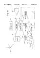
- FIGS. 1A-Bare block diagrams of the optical mensuration and correlation apparatus of the present invention showing the major components.
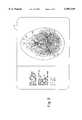
- FIG. 2is a perspective drawing illustrating the invention in use by a surgeon performing intracranial surgery on a patient, and showing a cursor on the display screen that marks the corresponding position of the invasive tip of the probe within the image of previously obtained model data.
- FIG. 3is a sample of the display showing a position of tip of the probe with respect to previously obtained model data and showing the reference points on the patient's skull display as triangles.
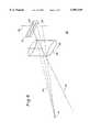
- FIG. 4is a schematic perspective representation of one of the one-dimensional photodetectors of the present invention.
- FIG. 5is a graph of the image intensity (manifested as a voltage or current) versus locations on the photodetector surface for a typical light detector used by the optical mensuration and correlation apparatus of the present invention.
- FIGS. 6 and 7are diagrams of the major steps performed by the computer to calculate the position of the invasive portion of the probe with respect to the model of the object and to display the image slice.
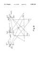
- FIG. 8is an illustration of the manner in which the three one-dimensional measurements determine three intersecting planes intersecting at a uniquely determined point.
- the optical mensuration and correlation apparatus 10 of the present inventionis shown schematically in FIG. 1 and comprises a hand-held invasive probe 12 housing at least two light emitters 14, 16, mounted co-linear with one another and with the tip 18 of the probe 12. At least thee remotely located, one-dimensional light energy sensors 20, 22, and 24 are mounted in fixed, spaced relationship to each other and are located at known positions and orientations with respect to a predetermined reference coordinate system frame 80. Three light sensors 20, 22, and 24 sense the light projected by the individual light emitters 14, 16 and generate electrical output signals from which are derived the location of the probe 12 and, consequently, the probe tip 18, with respect to the fixed coordinate system 80.
- the three sensors 20, 22, 24could sense and derive the locations of other, optional reference emitters 70, 72 and 74 (FIG. 1B) in the same manner for the probe emitters 14 and 16.
- the role of these reference emittersis to automate the calculation of the transformation matrix between the coordinate system of the model's image 13 (FIG. 2) of the object and the coordinate system of the sensors and the object itself 11.
- a control unit 30connected to the moveable probe 12 via a data line 26 and coupled to the remotely located sensors 20, 22, and 24 via data lines 28, 23, and 34, respectively, synchronizes the time multiplexing of the two light emitters 14, 16, controls the operation of the sensors 20, 22, and 24, and receives data from these sensors as will be completely described below.
- a coordinate computer 36coupled to the control unit 30 by a data line 38, calculates the three-dimensional spatial positions of the probe 12 and the probe tip 18, and correlates those positions with data from a model 13 of the object 11 which has been previously stored electronically in an electronically accessible database 40 and from correlation information 42. Finally, the computer 36 displays a representation 76 of the position of the probe tip 18 with respect to the computer image 13 of the object 11 on display screen 44 (FIG. 2) as will be fully described below.
- the probe 12can be used without the cable 26 coupling it to the control unit 30 by employing distinctive modulation of the light emitters 14 and 16. For example, the pulse durations or frequencies of each can be different.
- the controller 30,by detecting the pulse duration or frequency, can determine to which light emitter the sensors 20, 22, and 24 are reacting.
- the optical mensuration and correlation apparatus 10 of the present inventionis primarily designed to aid surgeons performing delicate intracranial surgery, and the remaining description is directed to such a surgical embodiment although many other surgical applications besides cranial surgery are possible. Moreover, the optical mensuration and correlation apparatus 10 of this invention may be used for other purposes in many various non-medical fields.
- the physical object 11 of interestis the head or cranium of a patient
- the model of the craniumis constructed using a series of parallel internal image slices (of known mutual spatial relationship such as those obtained by means of computed tomography (CT) or nuclear magnetic resonance (NMR). These image slices are then digitized, forming a three-dimensional computer model of the patient's cranium which is then stored in the electronically accessible database 40.
- CTcomputed tomography
- NMRnuclear magnetic resonance
- a surgeonplaces the tip 18 of the probe 12 at any point on or inside the cranium 11 of the patient.
- the position sensors 20, 22, and 24detect the locations of the emitters 14, 16 attached to the portion of the probe 12 that remains outside the patient's body. That is, the light produced by the emitters 14, 16 must be visible to the sensors 20, 22, and 24.
- These point emitters 14, 16radiate light through a wide angle so that they are visible at the sensors over a wide range of probe orientations.
- the sensors 20, 22, and 24, the control unit 30, and the computer 36determine the three-dimensional location of each emitter 14, 16, and compute its coordinates in the predetermined coordinate system 80.
- the computer 36can then calculate the location of the tip 18 of the probe 12 with respect to the predetermined coordinate system 80, according to the locations of the emitters with respect to the predetermined coordinate system 80 and the dimensions of the probe, which dimensions had been placed into the memory (not shown) of the computer 36 beforehand as will be described fully below.
- the computer 36uses the relationship between the model of the cranium stored in the database 40 and the coordinate system 80 to calculate the location of the probe tip 18 in relation to the model 11.
- the computer 36displays the model-relative location 76 of the tip 18 on a display screen 44.
- the computer 36accomplishes this display by accessing a CT or NMR image slice 13 stored in the database 40 that is closest to the location of the probe tip 18, and then superimposes a suitable icon 76 representing the tip 18 on the image 13 as shown in FIGS. 2 and 3.
- the surgeonknows the precise location of the probe tip 18 in the patient's cranium relative to the image data by merely observing the display screen 44.
- An advanced form of the present inventioncould derive and display an arbitrary oblique cross-section through the multiple image slices, where the cross-section is perpendicular to the probe direction.
- the probe 12houses the two light emitters 14, 16, which are rigidly attached to the probe 12. Since only two emitters are used, the emitters 14, 16 must be collinear with the tip 18 of the probe 12 so that the computer 36 can determine uniquely the position of the tip 18 in three dimensions. Moreover, for reasonable measurement accuracy, the emitters 14, 16 should be at least as far from each other as they are from the tip 18. In any case, the geometrical relationship of the emitters 14, 16 to each other and to the probe tip 18 should be specified to the computer 36 beforehand so that the computer 36 can compute the exact location and orientation of the tip 18 based on the locations of the individual light emitters 14, 16.
- the use of three emittersdoes not require that the probe tip be colinear with the emitters. Three or more emitters provides full orientation information.
- the inventionis described as showing only a cursor as locating the relative position of the probe tip 18, the invention can be modified to display a line or shaped graphic to indicate the location of the points of all of the inserted portion of the probe. This would entail only the determination of additional points along the probe.
- the two light emitters 14, 16can be high intensity light emitting diodes (LEDs), which are preferably time multiplexed or strobed by control unit 30 in a predetermined manner such that only one light emitter LED is "on” or emitting light at any one time as will be described in more detail below.
- LEDshigh intensity light emitting diodes
- the light emitted from any one of these emitters 14, 16is detected by each of the three emitter sensors 20, 22, and 24, which then determine the position of each particular emitter in relation to the known positions of the detectors 20, 22, and 24 at the time it is strobed or illuminated.
- Each of the one-dimensional sensors 20, 22, and 24 used in the preferred embodiment 10 of the present inventionare identical to one another in every respect. Therefore, for the purpose of giving a detailed description of this embodiment, only the sensor 20 is shown and described in detail, since the remaining sensors 22 and 24 are identical.
- a one-dimensional sensor 20comprises a cylindrical lens 46 having a longitudinal axis 48 which is orthogonal to the optical axis 50 of the sensor 20.
- a linear photodetector 52such as a charge coupled device (CCD) with several thousand elements or a similar device capable of linear light detection with an elongated aperture 54, is positioned in such a manner that the optical axis 50 passes through the aperture 54 and such that the long axis of the aperture 54 is orthogonal to the longitudinal axis 48 of the lens 46.
- Light beams 56 from the emitters 14, 16are focused by the cylindrical lens 46 into a real image line 58 on the surface 60 of linear photodetector 52.
- the photodetector 52then generates an output 68 (FIG. 5) that is related to the position of real image line 58 on the surface 60 of photodetector 52, thus characterizing the location of the image itself. That is, those elements of the detector 52 illuminated by the real image line 58 will generate a strong signal while those not illuminated will generate none or very small signals. Thus, a graph of image intensity (or signal strength) versus location on the surface of the photodetector will resemble the signal peak curve 68 shown in FIG. 5.
- the "all-emitters-off" (or background), signal level 66is never quite zero due to the effects of environmental light, electronic noise, and imperfections in the sensor. In any event, since the image of the illuminated emitter is focused into line 58, only the horizontal displacement of emitter 14 from optical axis 50 is measured by detector 52, hence the designation "one-dimensional detector.”
- a single one-dimensional detector 20can only locate the plane on which an illuminated emitter 14 lies, and the detector 20 cannot, by itself, determine the unique point in space at which illuminated emitter 14 is located.
- To precisely locate the location in space of the illuminated emitter 14requires three such detectors positioned in spaced relationship to each other since the intersection of three planes are required to define a point.
- the light sensors 20, 22, and 24are mounted so that their optical axes are not all parallel.
- two light sensorssuch as sensors 20, 24 in FIG. 2 are situated so that their respective axes 48 (FIG. 4) are in parallel spaced relationship with the third detector 22 situated between the other two but with its axis 48 perpendicular to the axes of the other two. That is, the sensors 20, 22, and 24 should be arranged along a line or arc (FIG. 2), such that each sensor 20, 22, and 24 is generally equidistant from the center of the volume in which the measurements are made equally spaced, and all aimed at the center of the measurement volume.
- the middle sensorshould be oriented so as to measure the angular elevation of the light emitters as described above.
- the two outer sensorstherefore, measure the horizontal angle (azimuth) relative to themselves. Data from the outer sensors are used to stereographically calculate both horizontal position and distance from the sensors as will be described below.
- the accuracy of three-dimensional measurementsdepends on the angle formed between the outer two sensors 20 and 24, where the emitter to be measured is at the vertex of the angle. Accuracy improves as that angle approaches a right angle. All three sensors 20, 22, and 24 must be spaced so that the desired measurement volume is completely within their field of view which can be accomplished by making the focal length of the lens 46 short enough to provide coverage of the desired field of view. Alternatively, additional sensors, identical to sensors 20, 22, and 4, could be used either to broaden coverage of the field of view or to enhance measurement resolution.
- the sensors 20, 22, and 24can detect the exact position of each emitter in turn.
- computer 36can determine the exact location and orientation of the probe tip 18. Since only one of the emitters 14, 16 is on at any one time, the detectors 20, 22, and 24 locate the position of that particular illuminated emitter only. If the strobe rate, that is, the frequency at which the emitters 14, 16 are turned on and off in sequence, is fast enough, the detectors 20, 22, and 24 can, for all practical purposes, determine the position and orientation of the probe tip 18 at any instant in time.
- the detectors or sensors 20, 22, and 24need only distinguish which of the light emitters 14, 16 is “on” or illuminated at any one time. In the preferred embodiment 10 of the present invention, this function is accomplished by strobing or illuminating each of the emitters 14, 16 in sequence, as described above. However, other methods could be used to allow the detectors or sensors 20, 22, and 24 to distinguish the respective pilot light emitters 14, 16 from one another. For example, different colors of light could be used in conjunction with detectors capable of distinguishing those particular colors or wavelengths of light. Alternatively, the respective light emitters 14, 16 could be modulated with a unique "tone" for each emitter. The control unit 30 or computer 36 could then be programmed to demodulate the tone, to determine to which particular emitter 14 or 16 the position signal belongs. Numerous other methods of distinguishing the light emitters 14 and 16 are possible and would be readily apparent to persons having ordinary skill in the art. Therefore, the present invention should not be regarded as limited to the particular strobing method shown and described herein.
- Auto-focusing or multiple-lens opticsmay be integrated into the sensors 20, 22, and 24 to improve the performance of the system.
- the simple, fixed-focus optics shown and described herein and in FIG. 4 for one sensorprovide a good level of performance if the focal length of the lenses 46 are kept short and if the working range of the probe 12 is restricted. Even if the real image of a light emitter 14 or 16 is somewhat out of focus on the photodetector 52, the angular measurement of the image is still useable.
- a useable measurement for each of the sensors 20, 22, or 24 to generatecould be any of the following: (1) the position of the photodetector element with peak intensity, (2) the intensity-weighted average of all overthreshhold elements, or simply (3) the average of the minimum and maximum elements where the intensity is over some threshold as will be completely described below.
- the photodetector 52should be placed at the focus for the farthest typical operating distance of the light emitters. Closer emitters will form slightly de-focused images 58, but they require less precise angular measurement for a given distance accuracy. Furthermore, their de-focused real images are brighter, which increases the brightness gradient at the edges of the image.
- the real image 58 of the currently activated emittermust be significantly brighter than the rest of the light falling on the photodetector 52. Otherwise, other lights or reflective surfaces in the field of view of the sensors will hinder the detection of the emitter's real image. Therefore, it is desirable to include in the apparatus circuitry to subtract the background light focused on the photodetectors as will be described in detail below.
- This circuitryenhances use of the invention where the sensors are to detect the light emitters against relatively bright backgrounds. While the light emitters are all momentarily extinguished, the one-dimensional data from each sensor are saved in a memory. This could be done in an analog delay line or by digitally sampling the output signal and storing it in a digital memory.
- the saved dataare subtracted from the current data generated by the illuminated emitter. If the background data are stored digitally, the new data is also digitized, and the stored background data is digitally subtracted from the new data.
- FIG. 5A graphical representation of the light intensity of the image, or equivalently, the generated output voltage amplitude for each element in the row of photodetector elements, is shown in FIG. 5.
- the graphdepicts typical background image intensities 66 with all emitters off, the intensities 68 with one light emitter on, and the element-by-element difference 64 between the intensities with the emitter off and those with it on.
- the measurementswill likely contain some random electronic noise, and two consecutive measurements for a given photodetector element may differ slightly even where the background is unchanged. Therefore, the differential intensities 64 between two consecutive measurements 66, 68 also contain some random electronic noise. However, the two measurements differ substantially only at the location of the light emitter image, and this difference exceeds the threshold level 62.
- control unit 30supplies power to the light emitters 14, 16, and the light sensors 20, 22, and 24.
- a control and synchronization unit 84 and light source sequencer 88time-multiplexes or strobes the emitter lights 14, 16 individually, as described above, so that the position and orientation of the probe tip 18 (FIG. 1) can be determined from the signals received from the light sensors 20, 22, and 24.
- the angular data signals received from the light sensors 20, 22, and 24are converted by an analog-to-digital converter 92.
- three analog-to-digital convertersare used, as shown in FIG. 6, but only one is labeled and described herein for brevity since the other two analog-to-digital converters are identical and are used to convert the signals from the sensors 22 and 24.
- the control and synchronization unit 84also controls three switches, of which switch 93 is typical, which store all digital data received from the sensors 20, 22, and 24 when the light emitters 14, 16 are off and stores these data in a background memory 94. Then, when the light emitters 14, 16 are illuminated in sequence by light source sequencer 18, the control and synchronization unit 84 changes the state of switch 93 which then redirects the data from the three sensors 20, 22, and 24 to a subtraction unit 91. The subtraction unit 91 subtracts the background data from the illuminated data, thus resulting in a signal relatively free from the background noise signal 66 (FIG. 5) since it has been subtracted from the signal.
- switch 93is typical, which store all digital data received from the sensors 20, 22, and 24 when the light emitters 14, 16 are off and stores these data in a background memory 94. Then, when the light emitters 14, 16 are illuminated in sequence by light source sequencer 18, the control and synchronization unit 84 changes the state of switch 93 which then redirects the data from the three sensors
- a 1-D (one-dimensional) position calculation unit 95determines the location of the real image line 58 on the CCD sensor 52 (FIG. 4) by measuring the locations of the edges 67, 69 of the signal blip 68 (FIG. 5) generated by the CCD sensor based on a predetermined threshold signal level 62. The 1-D position calculation unit 95 then averages the distance between the two edges to find the center of the signal peak as shown in FIG. 5. This method of determining the center of the signal peak is well known in the art and need not be described in further detail. Moreover, numerous other methods of determining the location of the signal peak or its centroid are known in the art and will be obvious to those of ordinary skill in the art.
- the method useddepends on the signal characteristics of the light sensor used as well as the characteristics of the lens system used to focus the light onto the surface of the detector, in addition to other parameters. Those practicing this invention with the various alternates described herein would have no trouble selecting a signal detection algorithm best suited to the particular characteristics of the sensors.
- control unit 30transmits the position data to the computer 36. That is when the computer 36 is ready to compute the current location of the illuminated emitter 14 or 16 on the probe 12, the latest angular data from all sensors 20, 22, and 24 are provided for analyzation. If the sensors generate data faster than the control unit 30 can process them, the unprocessed angular data are simply discarded.
- the operation of the computer 36is most advantageously set forth in FIG. 7.
- the computer 36calculates one-dimensional positions for each light emitter 14, 16, based on the location of the signal peak from each respective sensor 10, 22, and 24. These one-dimensional position signals are then used to determine the three-dimensional spatial coordinates of the emitters 14, 16, and thus for the probe 12 relative to the predetermined coordinate system 80 by coordinate transformation methods which are well-known in the art.
- the output signals from the computer 36can be in any form desired by the operator or required by the application system, such as XYZ coordinate triples based upon some predetermined stationary rectangular coordinate system 80.
- FIG. 8 and the following paragraphsdescribe in detail how the position of a single light emitter 14, 16 is determined from the data returned from the sensors 20, 22, and 24.
- the following descriptionapplies to these three sensors 20, 22, and 24 only. If there are more than three such sensors, the calculation can be performed using any three of the sensors. Furthermore, if more than three sensors are used, the average of the points calculated from all combinations of three sensors could be used to increase accuracy. Another option is to use the point calculated from the three sensors closest to the light emitters 14, 16.
- the following parametersare considered to be known:
- T[i]a parametric value between 0 and 1 indicating where the peak or center of the line image of the emitter intersects the line segment between DO[i] and DI[i] is supplied for each sensor.
- the coordinates of point Sare to be calculated, where S is the location of the light emitter.
- the three-dimensional coordinates of the above pointsare all referenced to a predetermined coordinate system 80.
- the cylindrical lens and linear photodetectordo not directly measure an angle A of the light emitter about its lens axis; rather, they measure a value T[i] linearly related to the tangent of that angle by
- Cis a constant of proportionality that is related to and determined empirically by, the dimensions of a particular system.
- Function F(t)could be a polynomial in variable T, or it could be a value interpolated from an empirically determined table.
- P[i]is a unique plane determined by the three points D[i], LO[i], and Ll[i], which are never collinear.
- Sis the point of intersection of the planes PO[1], P[2], and P[3] determined by sensors 20, 22, and 24.
- Sis a unique point if at least two sensor lens axes are not parallel and if no two lens axes are collinear. The intersection point is found by finding the common solution S of the three equations defining the planes P[i].
- the location of each of the probe's light emittersis computed, the location of the probe's tip 18 can be calculated. The method of making such a determination is well known using the teaching of analytic geometry and matrix manipulations.
- Mis a linear transformation matrix describing the relationship between a point R in the model space and a point S in the sensor space
- the imaging phaseprecedes the normal operation of the present invention.
- the body of the object of interestis used to build a three-dimensional geometrical model.
- the objectwas the head of a human intracanial surgical patient because the invention is advantageously used in stereotactic neurosurgery.
- the three-dimensional modelmay comprise digital data from a series of internal cross-sectional images obtained from computed tomography (CT), magnetic resonance (MR), ultrasound, or some other diagnostic medical scanner.
- CTcomputed tomography
- MRmagnetic resonance
- ultrasoundor some other diagnostic medical scanner.
- the image datastored in a suitable, electronic memory 40 which can be accessed later by the computer 36.
- the datais considered to be stored as a series of parallel two-dimensional rectangular arrays of picture elements (pixels), each pixel being an integer representing relative density. If the object is relatively rigid like a human head, this three-dimensional model may be created before the correlation and operational phases of the invention and possibly at another location.
- non-collinear reference points 71, 73, and 75(FIGS. 2 and 3), must be identified relative to the object 11. These may be represented by ink spots, tatoos, radiopaque beads, well-defined rigid anatomical landmarks, locations on a stereotactic frame, sterile pins temporarily inserted into rigid tissue or bone of a surgical patient, or some other reference means. The coordinates of these reference points are measured and recorded relative to the coordinate system of the imaging device. One way to accomplish this is to capture the reference points as part of the three dimensional model itself.
- radiopaque pinscould be placed within the image planes of diagnostic CT slices; the pin locations, if not automatically detectable because of their high density, can be identified interactively by the surgeon using a cursor on the computer display of the CT slices. See FIG. 3.
- the correlation modeimmediately precedes the normal operational phase of the present invention and must take place in the operating room.
- the inventionaccesses the data of the three-dimensional geometrical model of the patient, including the reference point coordinates which were recorded earlier.
- the surgeonplaces the tip of the probe 18 at each of the reference points 71, 73, and 75 on the patient, in turn, as directed by the computer program.
- Thisestablishes a relationship between the locations of these reference points in the model space and their current physical locations in the predetermined coordinate system 80. In turn, this establishes a linear mathematical relationship between all points the model and coordinate system 80.
- the position data 21 of the probe emitters 14, 16 generated by the sensors 20, 22, 24 and control unit 30are converted into three-dimensional coordinates relative to the predetermined coordinate space of the sensors 20, 22, 24.
- the computer 36uses dimensional parameters describing the relationship among the probe emitters 14, 16 and probe tip 18, the computer 36 determines the coordinates of the probe tip 22 in a step 39.
- the probe tip 22is placed at each of the reference points 71, 73, and 75. Their coordinates in the sensor space along with their coordinates 46 in the image space determine a unique linear transformation relating the two spaces in a step 45. This is a known calculation in analytic geometry and matrix mathematics.
- a more automated method of determining the locations of the reference points 71, 73, and 75is to place other emitters 70, 72 and 74 (FIG. 1B) at those reference points and use the sensors 20, 22, 24 to determine their locations relative to the predetermined coordinate system 80 of the sensors.
- the correlation phasecould be automatically initiated by the computer 36 except for the manual attachment of the additional emitters 70, 72, 74 at the reference points 71, 73, 75 just before using the device.
- the correlation phasecould be frequently but briefly repeated from time to time (continuously or initiated by the operator), interspersed in the operational phase for the purpose of recalculating the linear transformations M and M' should the object (such as a surgical patient) move relative to the sensors 20, 22, 24.
- the tip coordinatesare transformed in a step 44 using the transformation computed in the step 45.
- the new transformed coordinates, relative to the image space,are used to determine the plane of some two-dimensional cross-section through the three-dimensional image model 41 accessible in the accessible memory 43.
- the simplest methodis simply to choose the existing diagnostic image plane located closest to the probe tip's coordinates relative to the model space.
- a more advanced methodrequires synthesizing a cross-sectional image at some other angle through the model using the data from multiple image slices.
- a step 47transforms the two-dimensional cross-sectional slice to a screen image and places a cursor on it to mark the location of the probe tip in the image space. Scaling and viewing parameters determine how the image is displayed. Because the surgeon cannot simultaneously view the patient (object) and the computer display screen, the step 47 would only be executed when a button on the probe is pressed, freezing the image and the position of the probe tip marker at that instant.
- the computer systemcould generate the displayed image slice at an arbitrary angle, for example, in the plane perpendicular to the direction the probe is pointing.
- the computerwould simply display any one or more convenient image slices through the location of the probe tip.
- the displayed slicemight simply be the original CT slice closest to that location.
- the computerwould then display on the image a cursor at the current position of the probe tip.
- An alternative means to record the location of the reference points in the coordinate space of the imaging apparatus during the imaging phaseemploys an additional, separate instance of the three-dimensional position mensuration probe, sensors, control unit, and computer of the present invention.
- the additional sensorswould be permanently attached directly on the imaging apparatus.
- the additional probewould measure the location of the reference points at the time of imaging, and the additional control unit and computer would determine and record their locations relative to the coordinate system of the imaging apparatus.
- the advantage of this approachis that the landmarks or reference pins need not be within the limited cross-sectional slices visible to the imaging device.
- standard x-ray radiographs from several distinct directionscan be used to construct a crude model in lieu of the imaging phase described above. Radiographs from two or more directions would be digitally scanned, and four non-coplanar reference points on them would be identified with a cursor or light pen. In a correlation phase similar to that described above, these four points on the patient would be digitized just prior to surgery. Then, during surgery, the location of the probe tip would be projected onto digitized computer images of the two-dimensional radiographs where the projection is uniquely defined by mapping the reference point coordinates from the model space to the sensor spaces.
- a videotape recording of the computer screencould help document the performance of the procedure.
- Light emitterscould be present on more than one standard surgical tool such as the microscope, scalpel, forceps, and cauterizer, each of which would in effect be a probe.
- optical mensuration and correlation apparatus 10 of the present inventionhas been completely described. While some of the obvious and numerous modifications and equivalents have been described herein, still other modifications and changes will readily occur to those skilled in the art.
- the preferred embodimentuses visible light, since human operators can readily observe if the light sources are operative or whether they are causing troublesome reflections.
- other wavelengths of electromagnetic radiationcould be used without departing from the spirit and scope of the invention. Infrared light would have the advantage of not distracting the surgeon with flashing lights.
- Other modifications to the detector optics and lensesare possible which would alter the image characteristics on the sensors. For example, toroidal lenses could be used which are longitudinally curved along an arc with a radius equal to the focal length of the lens.
- the surfaces of the photodetectorscould also be curved, thus allowing the images of distant light sources to remain in sharp focus, regardless of their positions.
- Various measurements of the detector outputsare also possible. For example, the angle of peak intensity, the intensity-weighted average, or the average of the minimum and maximum angles where the intensity is over some predetermined threshold value could be used.
- numerous enhancements of the digital dataare possible by programming the computer to make the appropriate enhancements as would be obvious to those persons having ordinary skill in the art.
Landscapes
- Health & Medical Sciences (AREA)
- Life Sciences & Earth Sciences (AREA)
- Engineering & Computer Science (AREA)
- Medical Informatics (AREA)
- Surgery (AREA)
- Biomedical Technology (AREA)
- Heart & Thoracic Surgery (AREA)
- Veterinary Medicine (AREA)
- Molecular Biology (AREA)
- Animal Behavior & Ethology (AREA)
- General Health & Medical Sciences (AREA)
- Public Health (AREA)
- Pathology (AREA)
- Nuclear Medicine, Radiotherapy & Molecular Imaging (AREA)
- Physics & Mathematics (AREA)
- Biophysics (AREA)
- Radiology & Medical Imaging (AREA)
- Oral & Maxillofacial Surgery (AREA)
- High Energy & Nuclear Physics (AREA)
- Optics & Photonics (AREA)
- Dentistry (AREA)
- Computer Vision & Pattern Recognition (AREA)
- Neurosurgery (AREA)
- Neurology (AREA)
- Human Computer Interaction (AREA)
- Robotics (AREA)
- Magnetic Resonance Imaging Apparatus (AREA)
- Length Measuring Devices By Optical Means (AREA)
- Image Processing (AREA)
- Measurement Of The Respiration, Hearing Ability, Form, And Blood Characteristics Of Living Organisms (AREA)
- Apparatus For Radiation Diagnosis (AREA)
- Measuring And Recording Apparatus For Diagnosis (AREA)
- Ultra Sonic Daignosis Equipment (AREA)
- Image Analysis (AREA)
Abstract
Description
This is a divisional of application Ser. No. 08/317,805, filed Oct. 04, 1994, now U.S. Pat. No. 5,622,170 which is a continuation of application Ser. No. 08/052,042, filed Apr. 22, 1993, now abandoned which is a continuation-in-part of application Ser. No. 07/909,097, filed Jul. 02, 1992, now U.S. Pat. No. 5,383,454 which is a continuation-in-part of application Ser. No. 07/600,753, filed Oct. 19, 1990, now abandoned.
1. Field of the Invention
This invention relates to an improved method and apparatus for determining, in real time, the position of the tip of an invasive probe inside a three-dimensional object and displaying its position relative to a geometrical model of that object visually displayed on a computer screen. More specifically, this invention relates to an improved method and apparatus of interactively determining the position of a probe tip inside the head of a patient during intracranial surgery relative to a three-dimensional internal diagnostic image of that patient.
2. Brief Description of the Prior Art
Computed tomography (CT), magnetic resonance imaging (MRI), and other methods provide important detailed internal diagnostic images of human medical patients. However, during surgery there often is no obvious, clear-cut relationship between points of interest in the diagnostic images and the corresponding points on the actual patient While anomalous tissue may be obviously distinct from normal healthy tissue in the images, the difference may not be as visible in the patient on the operating table. Furthermore, in intracranial surgery, the region of interest may not always be accessible to direct view. Thus, there exists a need for apparatus to help a surgeon relate locations in the diagnostic images to the corresponding locations in the actual anatomy and vice versa.
The related prior art can be divided into art which is similar to the present invention as a whole and art which is related to individual components of this invention.
Prior art similar to the present invention as a whole includes methods of correlating three-dimensional internal medical images of a patient with the corresponding actual physical locations on the patient in the operating room during surgery. U.S. Pat. No. 4,791,934 does describe a semi-automated system which does that, but it requires additional radiographic imaging in the operating room at the time of surgery as the means to correlate the coordinate systems of the diagnostic image and the live patient. Furthermore, the system uses a computer-driven robot arm to position a surgical tool. In particular, it does not display the location of an input probe positioned interactively by the surgeon.
There have been other attempts to solve the three-dimensional localization problem specifically for stereotactic surgery. One class of solutions has been a variety of mechanical frames, holders, or protractors for surgery (usually intracranial surgery). For examples sea U.S. Pat. Nos. 4,931,056; 4,875,478; 4,841,967; 4,809,694; 4,805,615; 4,723,544; 4,706,665; 4,651,732; and 4,638,798. Generally, these patents are intended to reproduce angles derived from the analysis of internal images, and most require rigidly screwing a stereotactic frame to the skull. In any case, these methods are all inconvenient, time-consuming, and prone to human error.
A more interactive method uses undesirable fluoroscopy in the operating room to help guide surgical tools (U.S. Pat. No. 4,750,487).
More relevant prior art discloses a system built specifically for stereotactic surgery and is discussed in the following reference:
David W. Robens, M.D., et al; "A Frameless Stereotaxic Integration of Computerized Tomographic Imaging and the Operating Microscope", J. Neurosurgery 65, October 1986.
It reports how a sonic three-dimensional digitizer was used to track the position and orientation of the field of view of a surgical microscope. Superimposed on the view in the microscope was the corresponding internal planar slice of a previously obtained computed tomographic (CT) image. The major disadvantages reported about this system were the inaccuracy and instability of the sonic mensuration apparatus.
Although the present invention does not comprise tie imaging apparatus used to generate the internal three-dimensional image or model of the human patient or other object, the invention does input the data from such an apparatus. Such an imaging device might be a computed tomography (CT) or magnetic resonance (MRI) imager. The invention inputs the data in an electronic digital format from such an imager over a conventional communication network or through magnetic tape or disk media.
The following description concentrates on the prior art related specifically to the localizing device, which measures the position of the manual probe and which is a major component of this invention. Previous methods and devices have been utilized to sense the position of a probe or object in three-dimensional space, and employ one of various mensuration methods.
Numerous three-dimensional mensuration methods project a thin beam or a plane of light onto an object and optically sense where the light intersects the object. Examples of simple distance rangefinding devices using this general approach are described in U.S. Pat. Nos. 4,660,970; 4,701,049; 4,705,395; 4,709,156; 4,733,969; 4,743,770; 4,753,528; 4,761,072; 4,764,016; 4,782,239; and 4,825,091. Examples of inventions using a plane of light to sense an object's shape include U.S. Pat. Nos. 4,821,200, 4,701,047, 4,705,401, 4,737,032, 4,745,290, 4,794,262, 4,821,200, 4,743,771, and 4,822,163. In the latter, the accuracy of the surface sample points is usually limited by the typically low resolution of the two-dimensional sensors usually employed (currently about 1 part in 512 for a solid state video camera). Furthermore, these devices do not support the capability to detect the location and orientation of a manually held probe for identifying specific points. Additionally, because of line-of-sight limitations, these devices are generally useless for locating a point within recesses, which is necessary for intracranial surgery.
The internal imaging devices themselves (such as computed tomography, magnetic resonance, or ultrasonic imaging) are unsuited for tracking the spatial location of the manually held probe even though they are unencumbered by line-of-sight restrictions.
A few other methods and apparatus relate to the present invention. They track the position of one or more specific moveable points in three-dimensional space. The moveable points are generally represented by small radiating emitters which move relative to fixed position sensors. Some methods interchange the roles of the emitters and sensors. The typical forms of radiation are light (U.S. Pat. No. 4,836,778), sound (U.S. Pat. No. 3,821,469), and magnetic fields (U.S. Pat. No. 3,983,474). Other methods include clumsy mechanical arms or cables (U.S. Pat. No. 4,779,212). Some electro-optical approaches use a pair of video cameras plus a computer to calculate the position of homologous points in a pair of stereographic video images (for example. U.S. Pat. Nos. 4,836,778 and 4,829,373). The points of interest may be passive reflectors or flashing light emitters. The latter simplify finding, distinguishing, and calculating the points.
Probes with a pointing tip and sonic localizing emitters on them have been publicly marketed for several years. The present invention also utilizes a stylus, but it employs tiny light emitters, not sound emitters, and the method of sensing their positions is different.
Additional prior art related to this patent is found in these references:
Fuchs, H.; Duran, J.; Johnson, B.; "Acquisition and 10 Modeling of Human Body Form Data", Proc. SPIE, vol. 166, 1978, pp. 94-102.
Mesqui, F.; Kaeser, F.; Fischer, P.; "Real-time, Non-invasive Recording and 3-D Display of the Functional Movements of an Arbitrary Mandible Point", SPIE Biostereometrics, Vol. 602, 1985, pp. 77-84.
Yamashita, Y.; Suzuki, N.; Oshima, M. "Three-Dimensional Stereometric Measurement System Using Optical Scanners, Cylindrical Lenses, and Line Sensors", Proc. SPIE, vol. 361, 1983, pp. 67-73.
The paper by Fuchs, et al., (1978) best describes the method used by the present invention to track the surgical probe in three-dimensional space. It is based on using three or more one-dimensional sensors, each comprising a cylindrical lens and a linear array of photodetectors such as a charge-coupled semiconductor device (CCD) or a differential-voltage position sensitive detector (PSD).
The sensors determine intersecting planes which all contain a single radiating light emitter. Calculation of the point of intersection of the planes gives the location of the emitter. The calculation is based on the locations, orientations, and other details concerning the one-dimensional sensors and is a straihtforward application of analytic geometry. This electro-optical method, however, has not been previously used for the purpose of the present invention.
Thus, there still remains a need for a complete apparatus which provides fast, accurate, safe, convenient mensuration of the three-dimensional position of a manual probe and which visually relates that position to the corresponding position on the image of a previously-generated three-dimensional model of an object.
A first objective of the present invention is to provide accurate, three-dimensional mensuration of the location and orientation of an instrument on or inside an object, which could be (but is not limited to) a surgical patient in an operating room.
A second objective of this invention is to provide an electro-optical mensuration system which is inexpensive, easy to use, reliable, and portable and which employs a manually positioned probe or other pointing instrument.
A third objective of this invention is to provide a simple, non-invasive means of establishing a correspondence between a predetermined coordinate system of the object and a coordinate system of a three-dimensional, geometrical computer model of that object where the computer model has been provided as input data to this invention.
A fourth objective of this invention is to relate a measured location on or inside the object to the corresponding location in the computer model of that object according to the established correspondence between the coordinate systems of the object and the model.
A fifth objective of this invention is to display a cut-away view or a cross-sectional slice of that model on the graphics screen of the invention, where the slice may be a planar cross-section of the geometrical model, where the slice approximately intersects the location in the model corresponding to the measured location. A marker may then be superimposed on the displaced slice to indicate the location on the slice corresponding to the measured location.
A sixth objective of this invention, is specifically to help a surgeon locate diseased tissue while avoiding healthy critical structures, especially in cranial neurosurgery.
Additional objects, advantages, and novel features of the invention shall be set forth in part in the following description and in part will become apparent to those skilled in the art upon examination of the following or may be learned by the practice of the invention. The objects and the advantages of the invention may be realized and attained by means of the instrumentalities and in combinations particularly pointed out in the appended claims.
To achieve the foregoing and other objects and in accordance with the invention, as embodied and broadly described herein, the optical mensuration and correlation apparatus comprises a hand held probe having an invasive tip for touching or for inserting into an object. Two or more light emitters mounted in spaced relation to each other on the external portion of the probe remaining outside the object are sequentially strobed to emit light. Three or more light sensors or detectors, the positions of which are known with respect to a predetermined coordinate system, detect the positions of the two or more light emitters positioned on the probe as they are strobed. A computer coupled to the probe and to the light sensors receives data from the sensors and calculates the position and orientation of the probe, with respect to the predetermined coordinate system. The computer then determines the position and orientation of the invasive portion of the probe inside the object by correlating the position of the invasive portion of the probe relative to the predetermined coordinate system with a model of the object defined relative to the predetermined coordinate system. A display device coupled to the computer indicates the location of the invasive portion of the probe in the object by displaying a representation of the location of the invasive portion of the probe with respect to the model of the object.
The method of this invention includes the steps of detecting the position of the probe relative to the predetermined coordinate system, computing the position and orientation of the invasive portion of the probe relative to the predetermined coordinate system, determining the position and orientation of the invasive portion of the probe inside the object by correlating the position of the invasive portion of the probe relative to the predetermined coordinate system with the model of the object, and indicating the location of the invasive portion of the probe in the object by displaying a representation of the location of the invasive portion of the probe with respect to the model of the object.
The accompanying drawing figures, illustrate a preferred embodiment of the present invention and, together with the description, serve to explain the principles of the invention.
FIGS. 1A-B are block diagrams of the optical mensuration and correlation apparatus of the present invention showing the major components.
FIG. 2 is a perspective drawing illustrating the invention in use by a surgeon performing intracranial surgery on a patient, and showing a cursor on the display screen that marks the corresponding position of the invasive tip of the probe within the image of previously obtained model data.
FIG. 3 is a sample of the display showing a position of tip of the probe with respect to previously obtained model data and showing the reference points on the patient's skull display as triangles.
FIG. 4 is a schematic perspective representation of one of the one-dimensional photodetectors of the present invention.
FIG. 5 is a graph of the image intensity (manifested as a voltage or current) versus locations on the photodetector surface for a typical light detector used by the optical mensuration and correlation apparatus of the present invention.
FIGS. 6 and 7 are diagrams of the major steps performed by the computer to calculate the position of the invasive portion of the probe with respect to the model of the object and to display the image slice.
FIG. 8 is an illustration of the manner in which the three one-dimensional measurements determine three intersecting planes intersecting at a uniquely determined point.
The optical mensuration andcorrelation apparatus 10 of the present invention is shown schematically in FIG. 1 and comprises a hand-heldinvasive probe 12 housing at least twolight emitters tip 18 of theprobe 12. At least thee remotely located, one-dimensionallight energy sensors system frame 80. Threelight sensors individual light emitters probe 12 and, consequently, theprobe tip 18, with respect to the fixed coordinatesystem 80. In addition, the threesensors optional reference emitters probe emitters
Acontrol unit 30 connected to themoveable probe 12 via adata line 26 and coupled to the remotely locatedsensors data lines light emitters sensors computer 36, coupled to thecontrol unit 30 by adata line 38, calculates the three-dimensional spatial positions of theprobe 12 and theprobe tip 18, and correlates those positions with data from amodel 13 of the object 11 which has been previously stored electronically in an electronicallyaccessible database 40 and fromcorrelation information 42. Finally, thecomputer 36 displays arepresentation 76 of the position of theprobe tip 18 with respect to thecomputer image 13 of the object 11 on display screen 44 (FIG. 2) as will be fully described below.
Theprobe 12 can be used without thecable 26 coupling it to thecontrol unit 30 by employing distinctive modulation of thelight emitters controller 30, by detecting the pulse duration or frequency, can determine to which light emitter thesensors
The optical mensuration andcorrelation apparatus 10 of the present invention is primarily designed to aid surgeons performing delicate intracranial surgery, and the remaining description is directed to such a surgical embodiment although many other surgical applications besides cranial surgery are possible. Moreover, the optical mensuration andcorrelation apparatus 10 of this invention may be used for other purposes in many various non-medical fields. In the described embodiment, the physical object 11 of interest is the head or cranium of a patient, and the model of the cranium is constructed using a series of parallel internal image slices (of known mutual spatial relationship such as those obtained by means of computed tomography (CT) or nuclear magnetic resonance (NMR). These image slices are then digitized, forming a three-dimensional computer model of the patient's cranium which is then stored in the electronicallyaccessible database 40.
As shown in FIGS. 1A, 1B, 2, and 3 a surgeon places thetip 18 of theprobe 12 at any point on or inside the cranium 11 of the patient. Theposition sensors emitters probe 12 that remains outside the patient's body. That is, the light produced by theemitters sensors point emitters
Thesensors control unit 30, and thecomputer 36 determine the three-dimensional location of eachemitter system 80. Thecomputer 36 can then calculate the location of thetip 18 of theprobe 12 with respect to the predetermined coordinatesystem 80, according to the locations of the emitters with respect to the predetermined coordinatesystem 80 and the dimensions of the probe, which dimensions had been placed into the memory (not shown) of thecomputer 36 beforehand as will be described fully below. Once thecomputer 36 has calculated the location of theprobe tip 18 with respect to the predetermined coordinatesystem 80, thecomputer 36 then uses the relationship between the model of the cranium stored in thedatabase 40 and the coordinatesystem 80 to calculate the location of theprobe tip 18 in relation to the model 11. Finally, thecomputer 36 displays the model-relative location 76 of thetip 18 on adisplay screen 44. In a simple form of the preferred embodiment, thecomputer 36 accomplishes this display by accessing a CT orNMR image slice 13 stored in thedatabase 40 that is closest to the location of theprobe tip 18, and then superimposes asuitable icon 76 representing thetip 18 on theimage 13 as shown in FIGS. 2 and 3. Thus, the surgeon knows the precise location of theprobe tip 18 in the patient's cranium relative to the image data by merely observing thedisplay screen 44. An advanced form of the present invention could derive and display an arbitrary oblique cross-section through the multiple image slices, where the cross-section is perpendicular to the probe direction.
The details of the optical mensuration andcorrelation apparatus 10 of the present invention are best understood by reference to FIGS. 1 and 4 collectively. Essentially, theprobe 12 houses the twolight emitters probe 12. Since only two emitters are used, theemitters tip 18 of theprobe 12 so that thecomputer 36 can determine uniquely the position of thetip 18 in three dimensions. Moreover, for reasonable measurement accuracy, theemitters tip 18. In any case, the geometrical relationship of theemitters probe tip 18 should be specified to thecomputer 36 beforehand so that thecomputer 36 can compute the exact location and orientation of thetip 18 based on the locations of theindividual light emitters probe tip 18, the invention can be modified to display a line or shaped graphic to indicate the location of the points of all of the inserted portion of the probe. This would entail only the determination of additional points along the probe.
The twolight emitters control unit 30 in a predetermined manner such that only one light emitter LED is "on" or emitting light at any one time as will be described in more detail below. The light emitted from any one of theseemitters emitter sensors detectors
Each of the one-dimensional sensors preferred embodiment 10 of the present invention are identical to one another in every respect. Therefore, for the purpose of giving a detailed description of this embodiment, only thesensor 20 is shown and described in detail, since the remainingsensors
In FIG. 4, a one-dimensional sensor 20 comprises acylindrical lens 46 having alongitudinal axis 48 which is orthogonal to theoptical axis 50 of thesensor 20. Alinear photodetector 52, such as a charge coupled device (CCD) with several thousand elements or a similar device capable of linear light detection with anelongated aperture 54, is positioned in such a manner that theoptical axis 50 passes through theaperture 54 and such that the long axis of theaperture 54 is orthogonal to thelongitudinal axis 48 of thelens 46. Light beams 56 from theemitters cylindrical lens 46 into areal image line 58 on thesurface 60 oflinear photodetector 52.
Thephotodetector 52 then generates an output 68 (FIG. 5) that is related to the position ofreal image line 58 on thesurface 60 ofphotodetector 52, thus characterizing the location of the image itself. That is, those elements of thedetector 52 illuminated by thereal image line 58 will generate a strong signal while those not illuminated will generate none or very small signals. Thus, a graph of image intensity (or signal strength) versus location on the surface of the photodetector will resemble thesignal peak curve 68 shown in FIG. 5. The "all-emitters-off" (or background),signal level 66 is never quite zero due to the effects of environmental light, electronic noise, and imperfections in the sensor. In any event, since the image of the illuminated emitter is focused intoline 58, only the horizontal displacement ofemitter 14 fromoptical axis 50 is measured bydetector 52, hence the designation "one-dimensional detector."
Thus, a single one-dimensional detector 20 can only locate the plane on which anilluminated emitter 14 lies, and thedetector 20 cannot, by itself, determine the unique point in space at which illuminatedemitter 14 is located. To precisely locate the location in space of theilluminated emitter 14 requires three such detectors positioned in spaced relationship to each other since the intersection of three planes are required to define a point.
To locate the position of a particular illuminated one ofemitters light sensors sensors third detector 22 situated between the other two but with itsaxis 48 perpendicular to the axes of the other two. That is, thesensors sensor sensors
The accuracy of three-dimensional measurements depends on the angle formed between the outer twosensors sensors lens 46 short enough to provide coverage of the desired field of view. Alternatively, additional sensors, identical tosensors
While this process of detecting the position of a givenilluminated emitter probe tip 18 in three-dimensional space. To do so with only two emitters requires that bothemitters probe tip 18, as described above. Also, the distances between each emitter 14 and 16, (as well as the distances between theemitters 14, 16) and theprobe tip 18 must be known and loaded into the memory of thecomputer 36 before thecomputer 36 can determine the location of theprobe tip 18 from the locations of theemitters emitters sensors computer 36 can determine the exact location and orientation of theprobe tip 18. Since only one of theemitters detectors emitters detectors probe tip 18 at any instant in time.
The detectors orsensors light emitters preferred embodiment 10 of the present invention, this function is accomplished by strobing or illuminating each of theemitters sensors pilot light emitters respective light emitters control unit 30 orcomputer 36 could then be programmed to demodulate the tone, to determine to whichparticular emitter light emitters
Auto-focusing or multiple-lens optics may be integrated into thesensors lenses 46 are kept short and if the working range of theprobe 12 is restricted. Even if the real image of alight emitter photodetector 52, the angular measurement of the image is still useable. A useable measurement for each of thesensors photodetector 52 should be placed at the focus for the farthest typical operating distance of the light emitters. Closer emitters will form slightlyde-focused images 58, but they require less precise angular measurement for a given distance accuracy. Furthermore, their de-focused real images are brighter, which increases the brightness gradient at the edges of the image.
As described so far, thereal image 58 of the currently activated emitter must be significantly brighter than the rest of the light falling on thephotodetector 52. Otherwise, other lights or reflective surfaces in the field of view of the sensors will hinder the detection of the emitter's real image. Therefore, it is desirable to include in the apparatus circuitry to subtract the background light focused on the photodetectors as will be described in detail below. This circuitry enhances use of the invention where the sensors are to detect the light emitters against relatively bright backgrounds. While the light emitters are all momentarily extinguished, the one-dimensional data from each sensor are saved in a memory. This could be done in an analog delay line or by digitally sampling the output signal and storing it in a digital memory. Then, as each emitter is turned on sequentially, the saved data are subtracted from the current data generated by the illuminated emitter. If the background data are stored digitally, the new data is also digitized, and the stored background data is digitally subtracted from the new data.
A graphical representation of the light intensity of the image, or equivalently, the generated output voltage amplitude for each element in the row of photodetector elements, is shown in FIG. 5. The graph depicts typical background image intensities 66 with all emitters off, theintensities 68 with one light emitter on, and the element-by-element difference 64 between the intensities with the emitter off and those with it on. The measurements will likely contain some random electronic noise, and two consecutive measurements for a given photodetector element may differ slightly even where the background is unchanged. Therefore, the differential intensities 64 between twoconsecutive measurements threshold level 62.
The details of the structure and operation of thecontrol unit 30 are best seen in FIG. 6. Specifically, control unit 30 (FIG. 1) supplies power to thelight emitters light sensors synchronization unit 84 andlight source sequencer 88 time-multiplexes or strobes the emitter lights 14, 16 individually, as described above, so that the position and orientation of the probe tip 18 (FIG. 1) can be determined from the signals received from thelight sensors light sensors digital converter 92. Actually, three analog-to-digital converters are used, as shown in FIG. 6, but only one is labeled and described herein for brevity since the other two analog-to-digital converters are identical and are used to convert the signals from thesensors
The control andsynchronization unit 84 also controls three switches, of which switch 93 is typical, which store all digital data received from thesensors light emitters background memory 94. Then, when thelight emitters light source sequencer 18, the control andsynchronization unit 84 changes the state ofswitch 93 which then redirects the data from the threesensors subtraction unit 91. Thesubtraction unit 91 subtracts the background data from the illuminated data, thus resulting in a signal relatively free from the background noise signal 66 (FIG. 5) since it has been subtracted from the signal.
As shown in FIG. 6 in conjunction with FIG. 5, a 1-D (one-dimensional)position calculation unit 95 determines the location of thereal image line 58 on the CCD sensor 52 (FIG. 4) by measuring the locations of theedges threshold signal level 62. The 1-Dposition calculation unit 95 then averages the distance between the two edges to find the center of the signal peak as shown in FIG. 5. This method of determining the center of the signal peak is well known in the art and need not be described in further detail. Moreover, numerous other methods of determining the location of the signal peak or its centroid are known in the art and will be obvious to those of ordinary skill in the art. The method used depends on the signal characteristics of the light sensor used as well as the characteristics of the lens system used to focus the light onto the surface of the detector, in addition to other parameters. Those practicing this invention with the various alternates described herein would have no trouble selecting a signal detection algorithm best suited to the particular characteristics of the sensors.
Finally, control unit 30 (FIG. 1) transmits the position data to thecomputer 36. That is when thecomputer 36 is ready to compute the current location of theilluminated emitter probe 12, the latest angular data from allsensors control unit 30 can process them, the unprocessed angular data are simply discarded.
The operation of thecomputer 36 is most advantageously set forth in FIG. 7. Thecomputer 36 calculates one-dimensional positions for eachlight emitter respective sensor emitters probe 12 relative to the predetermined coordinatesystem 80 by coordinate transformation methods which are well-known in the art. The output signals from thecomputer 36 can be in any form desired by the operator or required by the application system, such as XYZ coordinate triples based upon some predetermined stationary rectangular coordinatesystem 80.
FIG. 8 and the following paragraphs describe in detail how the position of asingle light emitter sensors sensors light emitters
DO[i], one endpoint of each linear photodetector i;
Dl[i], the other endpoint of linear photodetector i;
LO[i], one endpoint of the axis of each lens i; and
Ll[i], the other endpoint of the axis of lens i.
T[i], a parametric value between 0 and 1 indicating where the peak or center of the line image of the emitter intersects the line segment between DO[i] and DI[i] is supplied for each sensor.
The coordinates of point S are to be calculated, where S is the location of the light emitter.
For a CCD photodetector array, T[i] is the index of the element on which the center or peak of the image falls divided by the number of elements on the photodetector array, where i=1,2,3, . . . n, which is a number of sensors being used.
The three-dimensional coordinates of the above points are all referenced to a predetermined coordinatesystem 80. The cylindrical lens and linear photodetector do not directly measure an angle A of the light emitter about its lens axis; rather, they measure a value T[i] linearly related to the tangent of that angle by
tan(A)=C*(2*T[i] -1),
where C is a constant of proportionality that is related to and determined empirically by, the dimensions of a particular system.
The three-dimensional location where the image line intersects the linear photodetector is
D[i]=(1-T[i])*DO[i]+(T[i])*Dl[i]
If the lens is ideal, then S also lies in plane P[i]. In reality, the point D[i] might have to be computed by a non-linear function F(t) that corrects for non-linear aberrations of the lens or the photodetector:
D[i]=(1-F(T[i]))*DO[i]+(F(T[i]))*Dl[i]
Function F(t) could be a polynomial in variable T, or it could be a value interpolated from an empirically determined table.
P[i] is a unique plane determined by the three points D[i], LO[i], and Ll[i], which are never collinear. S is the point of intersection of the planes PO[1], P[2], and P[3] determined bysensors tip 18 can be calculated. The method of making such a determination is well known using the teaching of analytic geometry and matrix manipulations.
If M is a linear transformation matrix describing the relationship between a point R in the model space and a point S in the sensor space, then
R*M=S.
If M' is the inverse of M and if S is a point in the sensor space, then the point in the model space corresponding to S is
R*M'=S.
The preliminary steps required before practicing the method of the invention are now described. Then, after fully describing these preliminary steps, the detailed steps of the method of the optical mensuration and correlation apparatus are described.
Use of the invention takes place in three phases: the imaging phase; the correlation phase; and the normal operational phase. The imaging phase precedes the normal operation of the present invention. During the imaging phase, the body of the object of interest is used to build a three-dimensional geometrical model. In the preceding description, the object was the head of a human intracanial surgical patient because the invention is advantageously used in stereotactic neurosurgery. Accordingly, the three-dimensional model may comprise digital data from a series of internal cross-sectional images obtained from computed tomography (CT), magnetic resonance (MR), ultrasound, or some other diagnostic medical scanner. In any case, the image data stored in a suitable,electronic memory 40 which can be accessed later by thecomputer 36. The data is considered to be stored as a series of parallel two-dimensional rectangular arrays of picture elements (pixels), each pixel being an integer representing relative density. If the object is relatively rigid like a human head, this three-dimensional model may be created before the correlation and operational phases of the invention and possibly at another location.
Also, during the imaging phase, at least threenon-collinear reference points
The correlation mode immediately precedes the normal operational phase of the present invention and must take place in the operating room. During the correlation phase, the invention accesses the data of the three-dimensional geometrical model of the patient, including the reference point coordinates which were recorded earlier. Next the surgeon places the tip of theprobe 18 at each of thereference points system 80. In turn, this establishes a linear mathematical relationship between all points the model and coordinatesystem 80. Thereafter, if the patient is ever moved relative to the sensors, a new relationship must be defined by again digitizing thereference points system 80. That is, the correlation phase must be repeated. Thereafter, a surgeon can relate any locations of interest on the diagnostic images with the corresponding physical locations on his patient during an operation, and vice versa. These could be locations accessible to theprobe tip 18 but not necessarily directly visible to the surgeon.
Having described the function and purpose of the preliminary steps, the detailed method of the present invention is more easily understood. As shown in FIG. 7, theposition data 21 of theprobe emitters sensors control unit 30 are converted into three-dimensional coordinates relative to the predetermined coordinate space of thesensors probe emitters probe tip 18, thecomputer 36 determines the coordinates of theprobe tip 22 in astep 39. During the correlation phase, theprobe tip 22 is placed at each of thereference points coordinates 46 in the image space determine a unique linear transformation relating the two spaces in astep 45. This is a known calculation in analytic geometry and matrix mathematics.
A more automated method of determining the locations of thereference points other emitters sensors system 80 of the sensors. In that case, the correlation phase could be automatically initiated by thecomputer 36 except for the manual attachment of theadditional emitters reference points sensors
During normal operation, the tip coordinates are transformed in astep 44 using the transformation computed in thestep 45. The new transformed coordinates, relative to the image space, are used to determine the plane of some two-dimensional cross-section through the three-dimensional image model 41 accessible in theaccessible memory 43. The simplest method is simply to choose the existing diagnostic image plane located closest to the probe tip's coordinates relative to the model space.
A more advanced method requires synthesizing a cross-sectional image at some other angle through the model using the data from multiple image slices.
In any case, astep 47 transforms the two-dimensional cross-sectional slice to a screen image and places a cursor on it to mark the location of the probe tip in the image space. Scaling and viewing parameters determine how the image is displayed. Because the surgeon cannot simultaneously view the patient (object) and the computer display screen, thestep 47 would only be executed when a button on the probe is pressed, freezing the image and the position of the probe tip marker at that instant.
In a more complex variation of this invention, the computer system could generate the displayed image slice at an arbitrary angle, for example, in the plane perpendicular to the direction the probe is pointing. In simpler cases, the computer would simply display any one or more convenient image slices through the location of the probe tip. For example, the displayed slice might simply be the original CT slice closest to that location. In any case, the computer would then display on the image a cursor at the current position of the probe tip.
An alternative means to record the location of the reference points in the coordinate space of the imaging apparatus during the imaging phase employs an additional, separate instance of the three-dimensional position mensuration probe, sensors, control unit, and computer of the present invention. The additional sensors would be permanently attached directly on the imaging apparatus. The additional probe would measure the location of the reference points at the time of imaging, and the additional control unit and computer would determine and record their locations relative to the coordinate system of the imaging apparatus. The advantage of this approach is that the landmarks or reference pins need not be within the limited cross-sectional slices visible to the imaging device.
As an alternative to true three-dimensional images, standard x-ray radiographs from several distinct directions can be used to construct a crude model in lieu of the imaging phase described above. Radiographs from two or more directions would be digitally scanned, and four non-coplanar reference points on them would be identified with a cursor or light pen. In a correlation phase similar to that described above, these four points on the patient would be digitized just prior to surgery. Then, during surgery, the location of the probe tip would be projected onto digitized computer images of the two-dimensional radiographs where the projection is uniquely defined by mapping the reference point coordinates from the model space to the sensor spaces.
Lastly, a videotape recording of the computer screen (as well as the direct view of the surgeon and patient) could help document the performance of the procedure. Light emitters could be present on more than one standard surgical tool such as the microscope, scalpel, forceps, and cauterizer, each of which would in effect be a probe.
The method and apparatus of the optical mensuration andcorrelation apparatus 10 of the present invention has been completely described. While some of the obvious and numerous modifications and equivalents have been described herein, still other modifications and changes will readily occur to those skilled in the art. For instance, the preferred embodiment uses visible light, since human operators can readily observe if the light sources are operative or whether they are causing troublesome reflections. Clearly, other wavelengths of electromagnetic radiation could be used without departing from the spirit and scope of the invention. Infrared light would have the advantage of not distracting the surgeon with flashing lights. Other modifications to the detector optics and lenses are possible which would alter the image characteristics on the sensors. For example, toroidal lenses could be used which are longitudinally curved along an arc with a radius equal to the focal length of the lens. Similarly, the surfaces of the photodetectors could also be curved, thus allowing the images of distant light sources to remain in sharp focus, regardless of their positions. Various measurements of the detector outputs are also possible. For example, the angle of peak intensity, the intensity-weighted average, or the average of the minimum and maximum angles where the intensity is over some predetermined threshold value could be used. Finally, numerous enhancements of the digital data are possible by programming the computer to make the appropriate enhancements as would be obvious to those persons having ordinary skill in the art.
The foregoing is illustrative of the principles of the invention. Since numerous modifications and changes will readily occur to those skilled in the art given the teachings of the invention, it is not desired to limit the invention to the exact construction and operation shown and described. Accordingly, all suitable modifications and equivalents that may be resorted to in light of disclosure of the invention fall within the scope of the invention as defined by the following claims.
Claims (10)
1. A method for indicating a position of a moveable first object, that is positioned partially within a moveable second object, in real time, on at least one previously taken image comprising an inside view of the moveable second object, wherein the moveable first object and the at least one image of the moveable second object include corresponding reference points, respectively, said method comprising the steps of:
determining the position of a portion of the moveable first object, that is positioned within the moveable second object, relative to a plurality of first reference points located on said first object outside said second object, wherein said first reference points are also in known relationship with electromagnetic radiation emitters, respectively;
emitting first electromagnetic rays, respectively, from said plurality of first emitters, that are in known spatial relationship to said first reference points, to a plurality of first electromagnetic ray receivers unconnected to said first or second objects; wherein said first electromagnetic ray receivers are in known spatial relationships relative to a first three dimensional coordinate system;
determining first angles between at least two of said first electromagnetic rays and at least one reference line;
from said first angles, indirectly determining the locations of said plurality of emitters, relative to the plurality of first electromagnetic ray receivers and indirectly determining, therefrom the position and orientation of said first object relative to said first three dimensional coordinate system;
emitting second electromagnetic rays, respectively, from a plurality of second emitters, in known spatial relationship relative to a plurality of second reference points, to a plurality of second electromagnetic ray receivers unconnected to said first or second objects; wherein said electromagnetic ray receivers are in known spatial relationships relative to a second three dimensional coordinate system;
determining second angles between at least two of said second electromagnetic rays and at least one reference line;
from said second angles, indirectly determining the locations of a plurality of said second emitters, relative to the plurality of second electromagnetic ray receivers, and indirectly determining therefrom the position and orientation of said second object relative to said second three dimensional coordinate system;
correlating the thus independently determined positions and orientations of said first and second objects, whereby determining the position and orientation of the portion of the first object that is within the second object relative to a previously taken image of the inside of said second object;
translating the determined position and orientation of the portion of the first object that is within the second object, and of the second object, into a three dimensional coordination system that is common with that of a previously taken image of the inside of the second object;
displaying an image comprising a previously taken view of an inside of the moveable second object, which view includes the position of the translated position of the first object that is inside the second object; and
displaying an image corresponding to at least a portion of said first object correctly superimposed on an image of the inside of said second object in real time.
2. A method as claimed in claim 1 further including emitting electromagnetic rays from emitters that are in known spatial relationship to said first and second reference points.
3. A method as claimed in claim 1 including correlating and adjusting said orientations substantially every time said second object moves.
4. A method as claimed in claim 1, further including moving both said first and second objects in relation to each other and in relation to said three dimensional coordinate systems; and
tracking said movements on said display in real time.
5. A method for indicating a position of a tip of a moveable surgical probe, which is positioned partially within a moveable body of a patient, in real time, on at least one previously taken body image comprising an inside view of the moveable body, wherein the moveable body and the at least one image of the moveable body include corresponding reference and image points, respectively, said method comprising the steps of:
determining the position of the tip of the moveable surgical probe relative to a plurality of electromagnetic ray emitting, first reference points located on said probe outside said body;
emitting first electromagnetic rays, respectively, from said plurality of first reference points to a plurality of first electromagnetic ray receivers unconnected to said moveable body and unconnected to said probe; wherein said electromagnetic ray receivers are in known positions relative to a first three dimensional coordinate system;
determining first angles between at least two of said first electromagnetic rays and at least one reference line;
from said first angles, indirectly determining the position of said probe tip relative to said first three dimensional coordinate system;
emitting second electromagnetic rays, respectively, from a plurality of second reference points, disposed on said body, to a plurality of second electromagnetic ray receivers unconnected to said moveable body and unconnected to said probe; wherein said electromagnetic ray receivers are in known positions relative to a second three dimensional coordinate system;
determining second angles between at least two of said second electromagnetic rays and at least one reference line;
from said second angles, indirectly determining the positions of the plurality of electromagnetic ray emitting second reference points on the moveable body relative to the plurality of second electromagnetic ray receivers, whereby independently, indirectly determining the position and orientation of said moveable body relative to said second three dimensional coordinate system;
translating the determined position of the tip of the surgical probe into a three dimensional coordination system of the previously taken image of the inside of the moveable body;
translating the determined position of the moveable body into the three dimensional coordination system of the previously taken image of the inside of the moveable body;
displaying a body image comprising said previously taken inside view of the moveable body, which view includes the position of the translated position of the tip of the moveable surgical probe; and
displaying an image corresponding to said tip correctly superimposed on said body image in real time.
6. A method as claimed in claim 5, including making all of said three dimensional coordinate systems the same three dimensional coordinate system.
7. A method as claimed in claim 5 including receiving electromagnetic rays from both said first and second electromagnetic ray emitting points in a single set of electromagnetic ray receivers.
8. A method as claimed in claim 5 further including moving said surgical probe in real time and repeatedly determining the position of said tip in real time.
9. A method as claimed in claim 8 further including selecting an internal image of said moveable body to coordinate with at least some of the repeatedly determined positions of said surgical probe tip.
10. A method as claimed in claim 9 further including displaying, in real time, a representation of said repeatedly determined position of said surgical probe tip and said selected internal image of said moveable body sufficiently frequently to depict movement of said tip relative to internal structures of said body.
Priority Applications (2)
| Application Number | Priority Date | Filing Date | Title |
|---|---|---|---|
| US08/844,365US5987349A (en) | 1990-10-19 | 1997-04-18 | Method for determining the position and orientation of two moveable objects in three-dimensional space |
| US09/220,888US6442416B1 (en) | 1993-04-22 | 1998-12-28 | Determination of the position and orientation of at least one object in space |
Applications Claiming Priority (6)
| Application Number | Priority Date | Filing Date | Title |
|---|---|---|---|
| US60075390A | 1990-10-19 | 1990-10-19 | |
| US07909097US5383454B1 (en) | 1990-10-19 | 1992-07-02 | System for indicating the position of a surgical probe within a head on an image of the head |
| US5204593A | 1993-04-22 | 1993-04-22 | |
| US5204293A | 1993-04-22 | 1993-04-22 | |
| US08/317,805US5622170A (en) | 1990-10-19 | 1994-10-04 | Apparatus for determining the position and orientation of an invasive portion of a probe inside a three-dimensional body |
| US08/844,365US5987349A (en) | 1990-10-19 | 1997-04-18 | Method for determining the position and orientation of two moveable objects in three-dimensional space |
Related Parent Applications (1)
| Application Number | Title | Priority Date | Filing Date |
|---|---|---|---|
| US08/317,805DivisionUS5622170A (en) | 1990-10-19 | 1994-10-04 | Apparatus for determining the position and orientation of an invasive portion of a probe inside a three-dimensional body |
Publications (1)
| Publication Number | Publication Date |
|---|---|
| US5987349Atrue US5987349A (en) | 1999-11-16 |
Family
ID=26730097
Family Applications (4)
| Application Number | Title | Priority Date | Filing Date |
|---|---|---|---|
| US08/317,805Expired - LifetimeUS5622170A (en) | 1990-10-19 | 1994-10-04 | Apparatus for determining the position and orientation of an invasive portion of a probe inside a three-dimensional body |
| US08/844,365Expired - LifetimeUS5987349A (en) | 1990-10-19 | 1997-04-18 | Method for determining the position and orientation of two moveable objects in three-dimensional space |
| US08/967,890Expired - LifetimeUS5920395A (en) | 1993-04-22 | 1997-11-12 | System for locating relative positions of objects in three dimensional space |
| US09/220,888Expired - LifetimeUS6442416B1 (en) | 1993-04-22 | 1998-12-28 | Determination of the position and orientation of at least one object in space |
Family Applications Before (1)
| Application Number | Title | Priority Date | Filing Date |
|---|---|---|---|
| US08/317,805Expired - LifetimeUS5622170A (en) | 1990-10-19 | 1994-10-04 | Apparatus for determining the position and orientation of an invasive portion of a probe inside a three-dimensional body |
Family Applications After (2)
| Application Number | Title | Priority Date | Filing Date |
|---|---|---|---|
| US08/967,890Expired - LifetimeUS5920395A (en) | 1993-04-22 | 1997-11-12 | System for locating relative positions of objects in three dimensional space |
| US09/220,888Expired - LifetimeUS6442416B1 (en) | 1993-04-22 | 1998-12-28 | Determination of the position and orientation of at least one object in space |
Country Status (9)
| Country | Link |
|---|---|
| US (4) | US5622170A (en) |
| EP (2) | EP0700269B1 (en) |
| JP (1) | JPH08509144A (en) |
| AU (1) | AU6666894A (en) |
| CA (1) | CA2161126C (en) |
| DE (2) | DE69431875T2 (en) |
| IL (1) | IL109385A (en) |
| WO (1) | WO1994023647A1 (en) |
| ZA (1) | ZA942812B (en) |
Cited By (155)
| Publication number | Priority date | Publication date | Assignee | Title |
|---|---|---|---|---|
| US6124695A (en)* | 1996-09-19 | 2000-09-26 | Matsushita Electric Industrial Co., Ltd. | Cartesian coordinates robot |
| US6146390A (en) | 1992-04-21 | 2000-11-14 | Sofamor Danek Holdings, Inc. | Apparatus and method for photogrammetric surgical localization |
| US6235038B1 (en) | 1999-10-28 | 2001-05-22 | Medtronic Surgical Navigation Technologies | System for translation of electromagnetic and optical localization systems |
| US6239874B1 (en)* | 1996-11-18 | 2001-05-29 | Armstrong Healthcare Limited | Orientation detector arrangement |
| US6266142B1 (en)* | 1998-09-21 | 2001-07-24 | The Texas A&M University System | Noncontact position and orientation measurement system and method |
| JP2001293007A (en)* | 2000-04-12 | 2001-10-23 | Olympus Optical Co Ltd | Surgical navigation apparatus |
| US6327491B1 (en)* | 1998-07-06 | 2001-12-04 | Neutar, Llc | Customized surgical fixture |
| WO2002024051A2 (en) | 2000-09-23 | 2002-03-28 | The Board Of Trustees Of The Leland Stanford Junior University | Endoscopic targeting method and system |
| US6363940B1 (en) | 1998-05-14 | 2002-04-02 | Calypso Medical Technologies, Inc. | System and method for bracketing and removing tissue |
| US6370224B1 (en) | 1998-06-29 | 2002-04-09 | Sofamor Danek Group, Inc. | System and methods for the reduction and elimination of image artifacts in the calibration of x-ray imagers |
| US6374134B1 (en) | 1992-08-14 | 2002-04-16 | British Telecommunications Public Limited Company | Simultaneous display during surgical navigation |
| US6379302B1 (en) | 1999-10-28 | 2002-04-30 | Surgical Navigation Technologies Inc. | Navigation information overlay onto ultrasound imagery |
| US6381485B1 (en) | 1999-10-28 | 2002-04-30 | Surgical Navigation Technologies, Inc. | Registration of human anatomy integrated for electromagnetic localization |
| US6439576B1 (en)* | 1998-07-30 | 2002-08-27 | Merlin Technologies, Inc. | Electronic missile location |
| US6443960B1 (en)* | 2000-11-24 | 2002-09-03 | Neorad A/S | Apparatus for light beam guided biopsy |
| US6459927B1 (en) | 1999-07-06 | 2002-10-01 | Neutar, Llc | Customizable fixture for patient positioning |
| US6493573B1 (en) | 1999-10-28 | 2002-12-10 | Winchester Development Associates | Method and system for navigating a catheter probe in the presence of field-influencing objects |
| WO2002085212A3 (en)* | 2001-04-10 | 2002-12-12 | Koninkl Philips Electronics Nv | A fluoroscopy intervention method with a cone-beam |
| US6497134B1 (en) | 2000-03-15 | 2002-12-24 | Image Guided Technologies, Inc. | Calibration of an instrument |
| US20030031349A1 (en)* | 2001-07-27 | 2003-02-13 | G.D.S. Giorgi Dynamic Stereotaxy S.R.I. | Device and procedure for computer-assisted microsurgery |
| US6535756B1 (en) | 2000-04-07 | 2003-03-18 | Surgical Navigation Technologies, Inc. | Trajectory storage apparatus and method for surgical navigation system |
| US6559955B2 (en)* | 2000-06-13 | 2003-05-06 | Director-General Of National Institute Of Advanced Industrial Science And Technology, Ministry Of Economy, Trade And Industry | Straightness measuring apparatus for moving stage |
| US6557558B1 (en) | 1999-08-31 | 2003-05-06 | Hitachi, Ltd. | Medical treatment apparatus |
| WO2002047115A3 (en)* | 2000-12-04 | 2003-05-15 | Asyst Technologies | Self teaching robot |
| EP1330992A1 (en)* | 2002-01-23 | 2003-07-30 | Stiftung für Plastische und Aesthetische Wundheilung im Sondervermögen der DT Deutschen Stiftungstreuhend AG | Device and method for establishing the spatial position of an instrument relative to an object |
| US6611141B1 (en) | 1998-12-23 | 2003-08-26 | Howmedica Leibinger Inc | Hybrid 3-D probe tracked by multiple sensors |
| US6671538B1 (en)* | 1999-11-26 | 2003-12-30 | Koninklijke Philips Electronics, N.V. | Interface system for use with imaging devices to facilitate visualization of image-guided interventional procedure planning |
| US20040019266A1 (en)* | 2002-07-29 | 2004-01-29 | Omnisonics Medical Technologies, Inc. | Apparatus and method for radiopaque coating for an ultrasonic medical device |
| US6701179B1 (en) | 1999-10-28 | 2004-03-02 | Michael A. Martinelli | Coil structures and methods for generating magnetic fields |
| US6718194B2 (en) | 2000-11-17 | 2004-04-06 | Ge Medical Systems Global Technology Company, Llc | Computer assisted intramedullary rod surgery system with enhanced features |
| US6725080B2 (en) | 2000-03-01 | 2004-04-20 | Surgical Navigation Technologies, Inc. | Multiple cannula image guided tool for image guided procedures |
| US6730048B1 (en) | 2002-12-23 | 2004-05-04 | Omnisonics Medical Technologies, Inc. | Apparatus and method for ultrasonic medical device with improved visibility in imaging procedures |
| US6730926B2 (en) | 2001-09-05 | 2004-05-04 | Servo-Robot Inc. | Sensing head and apparatus for determining the position and orientation of a target object |
| US6747539B1 (en) | 1999-10-28 | 2004-06-08 | Michael A. Martinelli | Patient-shielding and coil system |
| US6757557B1 (en) | 1992-08-14 | 2004-06-29 | British Telecommunications | Position location system |
| US20040124105A1 (en)* | 2002-12-30 | 2004-07-01 | Keith Seiler | Packaged systems for implanting markers in a patient and methods for manufacturing and using such systems |
| US20040130729A1 (en)* | 2002-08-14 | 2004-07-08 | Bart Van Coppenolle | Optical probe for scanning the features of an object and methods therefor |
| US20040133101A1 (en)* | 2001-06-08 | 2004-07-08 | Mate Timothy P. | Guided radiation therapy system |
| US20040176686A1 (en)* | 2002-12-23 | 2004-09-09 | Omnisonics Medical Technologies, Inc. | Apparatus and method for ultrasonic medical device with improved visibility in imaging procedures |
| WO2004078039A1 (en)* | 2003-03-07 | 2004-09-16 | Philips Intellectual Property & Standards Gmbh | Device and method for locating an instrument within a body |
| US20040207661A1 (en)* | 2002-12-27 | 2004-10-21 | Kabushiki Kaisha Toshiba | Medical imaging apparatus which displays predetermined information in differentiable manner from others |
| US6812842B2 (en) | 2001-12-20 | 2004-11-02 | Calypso Medical Technologies, Inc. | System for excitation of a leadless miniature marker |
| US6822570B2 (en) | 2001-12-20 | 2004-11-23 | Calypso Medical Technologies, Inc. | System for spatially adjustable excitation of leadless miniature marker |
| US6838990B2 (en) | 2001-12-20 | 2005-01-04 | Calypso Medical Technologies, Inc. | System for excitation leadless miniature marker |
| US6892090B2 (en) | 2002-08-19 | 2005-05-10 | Surgical Navigation Technologies, Inc. | Method and apparatus for virtual endoscopy |
| US20050110255A1 (en)* | 2003-11-20 | 2005-05-26 | Little David R. | Internally tethered seat bladder for occupant weight estimation |
| US6947786B2 (en) | 2002-02-28 | 2005-09-20 | Surgical Navigation Technologies, Inc. | Method and apparatus for perspective inversion |
| US6990368B2 (en) | 2002-04-04 | 2006-01-24 | Surgical Navigation Technologies, Inc. | Method and apparatus for virtual digital subtraction angiography |
| US7007699B2 (en) | 1999-10-28 | 2006-03-07 | Surgical Navigation Technologies, Inc. | Surgical sensor |
| US20060058644A1 (en)* | 2004-09-10 | 2006-03-16 | Harald Hoppe | System, device, and method for AD HOC tracking of an object |
| US20060058648A1 (en)* | 2004-07-23 | 2006-03-16 | Eric Meier | Integrated radiation therapy systems and methods for treating a target in a patient |
| US20060095047A1 (en)* | 2004-10-08 | 2006-05-04 | De La Barrera Jose Luis M | System and method for performing arthroplasty of a joint and tracking a plumb line plane |
| USRE39133E1 (en) | 1997-09-24 | 2006-06-13 | Surgical Navigation Technologies, Inc. | Percutaneous registration apparatus and method for use in computer-assisted surgical navigation |
| US20060166176A1 (en)* | 2002-09-10 | 2006-07-27 | University Of Vermont And State Agricultural College | Mathematical circulatory system model |
| US7085400B1 (en) | 2000-06-14 | 2006-08-01 | Surgical Navigation Technologies, Inc. | System and method for image based sensor calibration |
| US20060173299A1 (en)* | 2004-12-14 | 2006-08-03 | Scimed Life Systems, Inc. | Systems and methods for improved three-dimensional imaging of a body lumen |
| US20060215176A1 (en)* | 2002-08-14 | 2006-09-28 | Bart Van Coppenolle | Optical probe for scanning the features of an object and methods thereof |
| US7130676B2 (en) | 1998-08-20 | 2006-10-31 | Sofamor Danek Holdings, Inc. | Fluoroscopic image guided orthopaedic surgery system with intraoperative registration |
| US7135978B2 (en) | 2001-09-14 | 2006-11-14 | Calypso Medical Technologies, Inc. | Miniature resonating marker assembly |
| US7217276B2 (en) | 1999-04-20 | 2007-05-15 | Surgical Navigational Technologies, Inc. | Instrument guidance method and system for image guided surgery |
| US20070179626A1 (en)* | 2005-11-30 | 2007-08-02 | De La Barrera Jose L M | Functional joint arthroplasty method |
| US7289839B2 (en) | 2002-12-30 | 2007-10-30 | Calypso Medical Technologies, Inc. | Implantable marker with a leadless signal transmitter compatible for use in magnetic resonance devices |
| US7313430B2 (en) | 2003-08-28 | 2007-12-25 | Medtronic Navigation, Inc. | Method and apparatus for performing stereotactic surgery |
| US20080039717A1 (en)* | 2006-08-11 | 2008-02-14 | Robert Frigg | Simulated bone or tissue manipulation |
| US7366562B2 (en) | 2003-10-17 | 2008-04-29 | Medtronic Navigation, Inc. | Method and apparatus for surgical navigation |
| US20080107305A1 (en)* | 2006-11-02 | 2008-05-08 | Northern Digital Inc. | Integrated mapping system |
| US20090043556A1 (en)* | 2007-08-07 | 2009-02-12 | Axelson Stuart L | Method of and system for planning a surgery |
| US7494468B2 (en) | 1999-10-05 | 2009-02-24 | Omnisonics Medical Technologies, Inc. | Ultrasonic medical device operating in a transverse mode |
| US7503895B2 (en) | 1999-10-05 | 2009-03-17 | Omnisonics Medical Technologies, Inc. | Ultrasonic device for tissue ablation and sheath for use therewith |
| US7525309B2 (en) | 2005-12-30 | 2009-04-28 | Depuy Products, Inc. | Magnetic sensor array |
| US7542791B2 (en) | 2003-01-30 | 2009-06-02 | Medtronic Navigation, Inc. | Method and apparatus for preplanning a surgical procedure |
| USRE40852E1 (en) | 1995-06-14 | 2009-07-14 | Medtronic Navigation, Inc. | Method and system for navigating a catheter probe |
| US7567834B2 (en) | 2004-05-03 | 2009-07-28 | Medtronic Navigation, Inc. | Method and apparatus for implantation between two vertebral bodies |
| US7570791B2 (en) | 2003-04-25 | 2009-08-04 | Medtronic Navigation, Inc. | Method and apparatus for performing 2D to 3D registration |
| US7599730B2 (en) | 2002-11-19 | 2009-10-06 | Medtronic Navigation, Inc. | Navigation system for cardiac therapies |
| US7606613B2 (en) | 1999-03-23 | 2009-10-20 | Medtronic Navigation, Inc. | Navigational guidance via computer-assisted fluoroscopic imaging |
| US7636595B2 (en) | 2004-10-28 | 2009-12-22 | Medtronic Navigation, Inc. | Method and apparatus for calibrating non-linear instruments |
| US7660623B2 (en) | 2003-01-30 | 2010-02-09 | Medtronic Navigation, Inc. | Six degree of freedom alignment display for medical procedures |
| US7697972B2 (en) | 2002-11-19 | 2010-04-13 | Medtronic Navigation, Inc. | Navigation system for cardiac therapies |
| US7725162B2 (en) | 2000-01-27 | 2010-05-25 | Howmedica Leibinger Inc. | Surgery system |
| US20100168765A1 (en)* | 2008-09-25 | 2010-07-01 | Prosurgics Ltd. | Surgical mechanism control system |
| US7763035B2 (en) | 1997-12-12 | 2010-07-27 | Medtronic Navigation, Inc. | Image guided spinal surgery guide, system and method for use thereof |
| US7794414B2 (en) | 2004-02-09 | 2010-09-14 | Emigrant Bank, N.A. | Apparatus and method for an ultrasonic medical device operating in torsional and transverse modes |
| US7835778B2 (en) | 2003-10-16 | 2010-11-16 | Medtronic Navigation, Inc. | Method and apparatus for surgical navigation of a multiple piece construct for implantation |
| US7835784B2 (en) | 2005-09-21 | 2010-11-16 | Medtronic Navigation, Inc. | Method and apparatus for positioning a reference frame |
| US7840253B2 (en) | 2003-10-17 | 2010-11-23 | Medtronic Navigation, Inc. | Method and apparatus for surgical navigation |
| US20100318099A1 (en)* | 2009-06-16 | 2010-12-16 | Intuitive Surgical, Inc. | Virtual measurement tool for minimally invasive surgery |
| US7998062B2 (en) | 2004-03-29 | 2011-08-16 | Superdimension, Ltd. | Endoscope structures and techniques for navigating to a target in branched structure |
| US8068648B2 (en)* | 2006-12-21 | 2011-11-29 | Depuy Products, Inc. | Method and system for registering a bone of a patient with a computer assisted orthopaedic surgery system |
| US8074662B2 (en) | 1999-10-28 | 2011-12-13 | Medtronic Navigation, Inc. | Surgical communication and power system |
| US8112292B2 (en) | 2006-04-21 | 2012-02-07 | Medtronic Navigation, Inc. | Method and apparatus for optimizing a therapy |
| USRE43328E1 (en) | 1997-11-20 | 2012-04-24 | Medtronic Navigation, Inc | Image guided awl/tap/screwdriver |
| US8165658B2 (en) | 2008-09-26 | 2012-04-24 | Medtronic, Inc. | Method and apparatus for positioning a guide relative to a base |
| US8175681B2 (en) | 2008-12-16 | 2012-05-08 | Medtronic Navigation Inc. | Combination of electromagnetic and electropotential localization |
| US8196589B2 (en) | 2003-12-24 | 2012-06-12 | Calypso Medical Technologies, Inc. | Implantable marker with wireless signal transmitter |
| US8239001B2 (en) | 2003-10-17 | 2012-08-07 | Medtronic Navigation, Inc. | Method and apparatus for surgical navigation |
| USRE43952E1 (en) | 1989-10-05 | 2013-01-29 | Medtronic Navigation, Inc. | Interactive system for local intervention inside a non-homogeneous structure |
| US8452068B2 (en) | 2008-06-06 | 2013-05-28 | Covidien Lp | Hybrid registration method |
| US8452375B2 (en) | 1998-05-14 | 2013-05-28 | Varian Medical Systems, Inc. | Systems and methods for locating and defining a target location within a human body |
| US8473026B2 (en) | 1994-09-15 | 2013-06-25 | Ge Medical Systems Global Technology Company | System for monitoring a position of a medical instrument with respect to a patient's body |
| US8473032B2 (en) | 2008-06-03 | 2013-06-25 | Superdimension, Ltd. | Feature-based registration method |
| US8494614B2 (en) | 2009-08-31 | 2013-07-23 | Regents Of The University Of Minnesota | Combination localization system |
| US8494613B2 (en) | 2009-08-31 | 2013-07-23 | Medtronic, Inc. | Combination localization system |
| US8611984B2 (en) | 2009-04-08 | 2013-12-17 | Covidien Lp | Locatable catheter |
| US8644907B2 (en) | 1999-10-28 | 2014-02-04 | Medtronic Navigaton, Inc. | Method and apparatus for surgical navigation |
| US8643850B1 (en) | 2010-03-02 | 2014-02-04 | Richard L. Hartman | Automated system for load acquisition and engagement |
| US8660635B2 (en) | 2006-09-29 | 2014-02-25 | Medtronic, Inc. | Method and apparatus for optimizing a computer assisted surgical procedure |
| US8663088B2 (en) | 2003-09-15 | 2014-03-04 | Covidien Lp | System of accessories for use with bronchoscopes |
| US8749797B1 (en) | 2010-03-02 | 2014-06-10 | Advanced Optical Systems Inc. | System and method for remotely determining position and orientation of an object |
| US8764725B2 (en) | 2004-02-09 | 2014-07-01 | Covidien Lp | Directional anchoring mechanism, method and applications thereof |
| US8790359B2 (en) | 1999-10-05 | 2014-07-29 | Cybersonics, Inc. | Medical systems and related methods |
| US8862200B2 (en) | 2005-12-30 | 2014-10-14 | DePuy Synthes Products, LLC | Method for determining a position of a magnetic source |
| US8905920B2 (en) | 2007-09-27 | 2014-12-09 | Covidien Lp | Bronchoscope adapter and method |
| US8932207B2 (en) | 2008-07-10 | 2015-01-13 | Covidien Lp | Integrated multi-functional endoscopic tool |
| US8971597B2 (en) | 2005-05-16 | 2015-03-03 | Intuitive Surgical Operations, Inc. | Efficient vision and kinematic data fusion for robotic surgical instruments and other applications |
| US9055881B2 (en) | 2004-04-26 | 2015-06-16 | Super Dimension Ltd. | System and method for image-based alignment of an endoscope |
| US9076212B2 (en) | 2006-05-19 | 2015-07-07 | The Queen's Medical Center | Motion tracking system for real time adaptive imaging and spectroscopy |
| US9168102B2 (en) | 2006-01-18 | 2015-10-27 | Medtronic Navigation, Inc. | Method and apparatus for providing a container to a sterile environment |
| US9186053B2 (en) | 2012-05-03 | 2015-11-17 | Covidien Lp | Methods of using light to repair hernia defects |
| US9237860B2 (en) | 2008-06-05 | 2016-01-19 | Varian Medical Systems, Inc. | Motion compensation for medical imaging and associated systems and methods |
| US9305365B2 (en) | 2013-01-24 | 2016-04-05 | Kineticor, Inc. | Systems, devices, and methods for tracking moving targets |
| US9381417B2 (en) | 2013-08-16 | 2016-07-05 | Shimano Inc. | Bicycle fitting system |
| US9402690B2 (en) | 2008-12-31 | 2016-08-02 | Intuitive Surgical Operations, Inc. | Efficient 3-D telestration for local and remote robotic proctoring |
| US9492240B2 (en) | 2009-06-16 | 2016-11-15 | Intuitive Surgical Operations, Inc. | Virtual measurement tool for minimally invasive surgery |
| US9575140B2 (en) | 2008-04-03 | 2017-02-21 | Covidien Lp | Magnetic interference detection system and method |
| US9606209B2 (en) | 2011-08-26 | 2017-03-28 | Kineticor, Inc. | Methods, systems, and devices for intra-scan motion correction |
| US9675424B2 (en) | 2001-06-04 | 2017-06-13 | Surgical Navigation Technologies, Inc. | Method for calibrating a navigation system |
| US9717461B2 (en) | 2013-01-24 | 2017-08-01 | Kineticor, Inc. | Systems, devices, and methods for tracking and compensating for patient motion during a medical imaging scan |
| US9734589B2 (en) | 2014-07-23 | 2017-08-15 | Kineticor, Inc. | Systems, devices, and methods for tracking and compensating for patient motion during a medical imaging scan |
| US9782141B2 (en) | 2013-02-01 | 2017-10-10 | Kineticor, Inc. | Motion tracking system for real time adaptive motion compensation in biomedical imaging |
| WO2017189450A1 (en)* | 2016-04-26 | 2017-11-02 | Magic Leap, Inc. | Electromagnetic tracking with augmented reality systems |
| US9911187B2 (en)* | 2015-08-19 | 2018-03-06 | Brainlab Ag | Determining a straight line trajectory for a medical procedure |
| US9943247B2 (en) | 2015-07-28 | 2018-04-17 | The University Of Hawai'i | Systems, devices, and methods for detecting false movements for motion correction during a medical imaging scan |
| US10004462B2 (en) | 2014-03-24 | 2018-06-26 | Kineticor, Inc. | Systems, methods, and devices for removing prospective motion correction from medical imaging scans |
| US10327708B2 (en) | 2013-01-24 | 2019-06-25 | Kineticor, Inc. | Systems, devices, and methods for tracking and compensating for patient motion during a medical imaging scan |
| US10418705B2 (en) | 2016-10-28 | 2019-09-17 | Covidien Lp | Electromagnetic navigation antenna assembly and electromagnetic navigation system including the same |
| US10426555B2 (en) | 2015-06-03 | 2019-10-01 | Covidien Lp | Medical instrument with sensor for use in a system and method for electromagnetic navigation |
| US10446931B2 (en) | 2016-10-28 | 2019-10-15 | Covidien Lp | Electromagnetic navigation antenna assembly and electromagnetic navigation system including the same |
| US10478254B2 (en) | 2016-05-16 | 2019-11-19 | Covidien Lp | System and method to access lung tissue |
| US10485450B2 (en)* | 2016-08-30 | 2019-11-26 | Mako Surgical Corp. | Systems and methods for intra-operative pelvic registration |
| US10517505B2 (en) | 2016-10-28 | 2019-12-31 | Covidien Lp | Systems, methods, and computer-readable media for optimizing an electromagnetic navigation system |
| US10582834B2 (en) | 2010-06-15 | 2020-03-10 | Covidien Lp | Locatable expandable working channel and method |
| US10615500B2 (en) | 2016-10-28 | 2020-04-07 | Covidien Lp | System and method for designing electromagnetic navigation antenna assemblies |
| US10638952B2 (en) | 2016-10-28 | 2020-05-05 | Covidien Lp | Methods, systems, and computer-readable media for calibrating an electromagnetic navigation system |
| US10716515B2 (en) | 2015-11-23 | 2020-07-21 | Kineticor, Inc. | Systems, devices, and methods for tracking and compensating for patient motion during a medical imaging scan |
| US10722311B2 (en) | 2016-10-28 | 2020-07-28 | Covidien Lp | System and method for identifying a location and/or an orientation of an electromagnetic sensor based on a map |
| US10751126B2 (en) | 2016-10-28 | 2020-08-25 | Covidien Lp | System and method for generating a map for electromagnetic navigation |
| US10792106B2 (en) | 2016-10-28 | 2020-10-06 | Covidien Lp | System for calibrating an electromagnetic navigation system |
| US10952593B2 (en) | 2014-06-10 | 2021-03-23 | Covidien Lp | Bronchoscope adapter |
| US11006914B2 (en) | 2015-10-28 | 2021-05-18 | Medtronic Navigation, Inc. | Apparatus and method for maintaining image quality while minimizing x-ray dosage of a patient |
| US11219489B2 (en) | 2017-10-31 | 2022-01-11 | Covidien Lp | Devices and systems for providing sensors in parallel with medical tools |
| US11244485B2 (en) | 2016-01-19 | 2022-02-08 | Magic Leap, Inc. | Augmented reality systems and methods utilizing reflections |
| US11331150B2 (en) | 1999-10-28 | 2022-05-17 | Medtronic Navigation, Inc. | Method and apparatus for surgical navigation |
| US12089902B2 (en) | 2019-07-30 | 2024-09-17 | Coviden Lp | Cone beam and 3D fluoroscope lung navigation |
| US12369981B2 (en) | 2023-02-07 | 2025-07-29 | Depuy Ireland Unlimited Company | Systems and methods for bone model registration with adaptive soft tissue thickness |
Families Citing this family (432)
| Publication number | Priority date | Publication date | Assignee | Title |
|---|---|---|---|---|
| US6331180B1 (en) | 1988-05-03 | 2001-12-18 | Sherwood Services Ag | Target-centered stereotaxtic surgical arc system with reorientatable arc axis |
| US5415169A (en)* | 1989-11-21 | 1995-05-16 | Fischer Imaging Corporation | Motorized mammographic biopsy apparatus |
| US6347240B1 (en) | 1990-10-19 | 2002-02-12 | St. Louis University | System and method for use in displaying images of a body part |
| DE69132412T2 (en) | 1990-10-19 | 2001-03-01 | St. Louis University, St. Louis | LOCALIZATION SYSTEM FOR A SURGICAL PROBE FOR USE ON THE HEAD |
| US5662111A (en)* | 1991-01-28 | 1997-09-02 | Cosman; Eric R. | Process of stereotactic optical navigation |
| US6167295A (en) | 1991-01-28 | 2000-12-26 | Radionics, Inc. | Optical and computer graphic stereotactic localizer |
| US6006126A (en) | 1991-01-28 | 1999-12-21 | Cosman; Eric R. | System and method for stereotactic registration of image scan data |
| US6405072B1 (en) | 1991-01-28 | 2002-06-11 | Sherwood Services Ag | Apparatus and method for determining a location of an anatomical target with reference to a medical apparatus |
| US6675040B1 (en)* | 1991-01-28 | 2004-01-06 | Sherwood Services Ag | Optical object tracking system |
| US5762458A (en)* | 1996-02-20 | 1998-06-09 | Computer Motion, Inc. | Method and apparatus for performing minimally invasive cardiac procedures |
| US5732703A (en)* | 1992-11-30 | 1998-03-31 | The Cleveland Clinic Foundation | Stereotaxy wand and tool guide |
| US5517990A (en)* | 1992-11-30 | 1996-05-21 | The Cleveland Clinic Foundation | Stereotaxy wand and tool guide |
| EP0700269B1 (en)* | 1993-04-22 | 2002-12-11 | Image Guided Technologies, Inc. | System for locating relative positions of objects |
| DE9422172U1 (en) | 1993-04-26 | 1998-08-06 | St. Louis University, St. Louis, Mo. | Specify the location of a surgical probe |
| NO302055B1 (en)* | 1993-05-24 | 1998-01-12 | Metronor As | Geometry measurement method and system |
| US5829444A (en)* | 1994-09-15 | 1998-11-03 | Visualization Technology, Inc. | Position tracking and imaging system for use in medical applications |
| US5695501A (en) | 1994-09-30 | 1997-12-09 | Ohio Medical Instrument Company, Inc. | Apparatus for neurosurgical stereotactic procedures |
| ATE228338T1 (en) | 1994-10-07 | 2002-12-15 | Univ St Louis | SURGICAL NAVIGATION ARRANGEMENT INCLUDING REFERENCE AND LOCATION SYSTEMS |
| US6978166B2 (en)* | 1994-10-07 | 2005-12-20 | Saint Louis University | System for use in displaying images of a body part |
| US5762064A (en)* | 1995-01-23 | 1998-06-09 | Northrop Grumman Corporation | Medical magnetic positioning system and method for determining the position of a magnetic probe |
| US6690963B2 (en) | 1995-01-24 | 2004-02-10 | Biosense, Inc. | System for determining the location and orientation of an invasive medical instrument |
| US6259943B1 (en)* | 1995-02-16 | 2001-07-10 | Sherwood Services Ag | Frameless to frame-based registration system |
| US6246898B1 (en)* | 1995-03-28 | 2001-06-12 | Sonometrics Corporation | Method for carrying out a medical procedure using a three-dimensional tracking and imaging system |
| US5868673A (en)* | 1995-03-28 | 1999-02-09 | Sonometrics Corporation | System for carrying out surgery, biopsy and ablation of a tumor or other physical anomaly |
| US6122541A (en)* | 1995-05-04 | 2000-09-19 | Radionics, Inc. | Head band for frameless stereotactic registration |
| KR19990029038A (en)* | 1995-07-16 | 1999-04-15 | 요아브 빨띠에리 | Free aiming of needle ceramic |
| US6256529B1 (en)* | 1995-07-26 | 2001-07-03 | Burdette Medical Systems, Inc. | Virtual reality 3D visualization for surgical procedures |
| US6714841B1 (en)* | 1995-09-15 | 2004-03-30 | Computer Motion, Inc. | Head cursor control interface for an automated endoscope system for optimal positioning |
| DE19639615C5 (en)* | 1996-09-26 | 2008-11-06 | Brainlab Ag | Reflector referencing system for surgical and medical instruments |
| US6351659B1 (en) | 1995-09-28 | 2002-02-26 | Brainlab Med. Computersysteme Gmbh | Neuro-navigation system |
| US5772594A (en)* | 1995-10-17 | 1998-06-30 | Barrick; Earl F. | Fluoroscopic image guided orthopaedic surgery system with intraoperative registration |
| US20020045812A1 (en) | 1996-02-01 | 2002-04-18 | Shlomo Ben-Haim | Implantable sensor for determining position coordinates |
| AU706052B2 (en) | 1996-02-15 | 1999-06-10 | Biosense, Inc. | Movable transmit or receive coils for location system |
| WO1997029710A1 (en) | 1996-02-15 | 1997-08-21 | Biosense, Inc. | Medical probes with field transducers |
| AU720441B2 (en) | 1996-02-15 | 2000-06-01 | Biosense, Inc. | Catheter with lumen |
| ES2241037T3 (en) | 1996-02-15 | 2005-10-16 | Biosense Webster, Inc. | PRECISE DETERMINATION OF THE POSITION OF ENDOSCOPES. |
| US6618612B1 (en) | 1996-02-15 | 2003-09-09 | Biosense, Inc. | Independently positionable transducers for location system |
| AU709081B2 (en) | 1996-02-15 | 1999-08-19 | Biosense, Inc. | Medical procedures and apparatus using intrabody probes |
| IL125755A (en) | 1996-02-15 | 2003-05-29 | Biosense Inc | Catheter calibration and usage monitoring system |
| CA2246332C (en) | 1996-02-15 | 2009-04-14 | Biosense, Inc. | Catheter based surgery |
| EP0886757B1 (en) | 1996-02-27 | 2005-05-25 | Biosense Webster, Inc. | Location system with field actuation sequences |
| DE19609564C1 (en)* | 1996-03-12 | 1997-06-26 | Fraunhofer Ges Forschung | Ultrasonic communication system for location of diagnostic capsule |
| US6177792B1 (en) | 1996-03-26 | 2001-01-23 | Bisense, Inc. | Mutual induction correction for radiator coils of an objects tracking system |
| US6167145A (en) | 1996-03-29 | 2000-12-26 | Surgical Navigation Technologies, Inc. | Bone navigation system |
| JP4183753B2 (en) | 1996-05-06 | 2008-11-19 | バイオセンス・ウェブスター・インコーポレイテッド | Radiator calibration |
| USRE40176E1 (en)* | 1996-05-15 | 2008-03-25 | Northwestern University | Apparatus and method for planning a stereotactic surgical procedure using coordinated fluoroscopy |
| US5795295A (en)* | 1996-06-25 | 1998-08-18 | Carl Zeiss, Inc. | OCT-assisted surgical microscope with multi-coordinate manipulator |
| US6167296A (en)* | 1996-06-28 | 2000-12-26 | The Board Of Trustees Of The Leland Stanford Junior University | Method for volumetric image navigation |
| US6611630B1 (en) | 1996-07-10 | 2003-08-26 | Washington University | Method and apparatus for automatic shape characterization |
| US6226418B1 (en) | 1997-11-07 | 2001-05-01 | Washington University | Rapid convolution based large deformation image matching via landmark and volume imagery |
| US6009212A (en) | 1996-07-10 | 1999-12-28 | Washington University | Method and apparatus for image registration |
| US6408107B1 (en) | 1996-07-10 | 2002-06-18 | Michael I. Miller | Rapid convolution based large deformation image matching via landmark and volume imagery |
| ATE197647T1 (en)* | 1996-08-22 | 2000-12-15 | Synthes Ag | 3-D ULTRASONIC RECORDING DEVICE |
| US6296613B1 (en) | 1997-08-22 | 2001-10-02 | Synthes (U.S.A.) | 3D ultrasound recording device |
| JP3198938B2 (en)* | 1996-09-03 | 2001-08-13 | 株式会社エフ・エフ・シー | Image processing device for mobile camera |
| US6364888B1 (en)* | 1996-09-09 | 2002-04-02 | Intuitive Surgical, Inc. | Alignment of master and slave in a minimally invasive surgical apparatus |
| JP3625845B2 (en)* | 1996-09-16 | 2005-03-02 | スナップ−オン テクノロジーズ インク. | Measuring instrument used mainly with vehicles |
| US5865744A (en)* | 1996-09-16 | 1999-02-02 | Lemelson; Jerome H. | Method and system for delivering therapeutic agents |
| DE19637822C1 (en)* | 1996-09-17 | 1998-03-26 | Deutsch Zentr Luft & Raumfahrt | Micromechanical tool |
| US5845646A (en)* | 1996-11-05 | 1998-12-08 | Lemelson; Jerome | System and method for treating select tissue in a living being |
| US6132441A (en) | 1996-11-22 | 2000-10-17 | Computer Motion, Inc. | Rigidly-linked articulating wrist with decoupled motion transmission |
| US7302288B1 (en)* | 1996-11-25 | 2007-11-27 | Z-Kat, Inc. | Tool position indicator |
| JP3814904B2 (en)* | 1996-12-25 | 2006-08-30 | ソニー株式会社 | Position detection device and remote control device |
| US6119033A (en)* | 1997-03-04 | 2000-09-12 | Biotrack, Inc. | Method of monitoring a location of an area of interest within a patient during a medical procedure |
| US6731966B1 (en) | 1997-03-04 | 2004-05-04 | Zachary S. Spigelman | Systems and methods for targeting a lesion |
| US6026315A (en)* | 1997-03-27 | 2000-02-15 | Siemens Aktiengesellschaft | Method and apparatus for calibrating a navigation system in relation to image data of a magnetic resonance apparatus |
| GB9706797D0 (en) | 1997-04-03 | 1997-05-21 | Sun Electric Uk Ltd | Wireless data transmission |
| US6708184B2 (en) | 1997-04-11 | 2004-03-16 | Medtronic/Surgical Navigation Technologies | Method and apparatus for producing and accessing composite data using a device having a distributed communication controller interface |
| US5970499A (en) | 1997-04-11 | 1999-10-19 | Smith; Kurt R. | Method and apparatus for producing and accessing composite data |
| US6669653B2 (en)* | 1997-05-05 | 2003-12-30 | Trig Medical Ltd. | Method and apparatus for monitoring the progress of labor |
| US6752812B1 (en) | 1997-05-15 | 2004-06-22 | Regent Of The University Of Minnesota | Remote actuation of trajectory guide |
| US5993463A (en) | 1997-05-15 | 1999-11-30 | Regents Of The University Of Minnesota | Remote actuation of trajectory guide |
| US5907395A (en)* | 1997-06-06 | 1999-05-25 | Image Guided Technologies, Inc. | Optical fiber probe for position measurement |
| DE69819289T2 (en)* | 1997-06-23 | 2004-08-05 | Philips Intellectual Property & Standards Gmbh | IMAGE GUIDED SURGICAL SYSTEM |
| EP0999785A4 (en)* | 1997-06-27 | 2007-04-25 | Univ Leland Stanford Junior | METHOD AND APPARATUS FOR GENERATING THREE-DIMENSIONAL IMAGES FOR "NAVIGATION" PURPOSES |
| US6055449A (en)* | 1997-09-22 | 2000-04-25 | Siemens Corporate Research, Inc. | Method for localization of a biopsy needle or similar surgical tool in a radiographic image |
| US6081336A (en)* | 1997-09-26 | 2000-06-27 | Picker International, Inc. | Microscope calibrator |
| US6147480A (en)* | 1997-10-23 | 2000-11-14 | Biosense, Inc. | Detection of metal disturbance |
| US6157853A (en)* | 1997-11-12 | 2000-12-05 | Stereotaxis, Inc. | Method and apparatus using shaped field of repositionable magnet to guide implant |
| EP1079730B1 (en)* | 1997-11-24 | 2007-01-03 | Computerized Medical Systems, Inc. | Real time brachytherapy spatial registration and visualization system |
| US6149592A (en)* | 1997-11-26 | 2000-11-21 | Picker International, Inc. | Integrated fluoroscopic projection image data, volumetric image data, and surgical device position data |
| US6052611A (en)* | 1997-11-28 | 2000-04-18 | Picker International, Inc. | Frameless stereotactic tomographic scanner for image guided interventional procedures |
| US6035228A (en)* | 1997-11-28 | 2000-03-07 | Picker International, Inc. | Frameless stereotactic arm apparatus and method of using same |
| US6064904A (en)* | 1997-11-28 | 2000-05-16 | Picker International, Inc. | Frameless stereotactic CT scanner with virtual needle display for planning image guided interventional procedures |
| US5967982A (en)* | 1997-12-09 | 1999-10-19 | The Cleveland Clinic Foundation | Non-invasive spine and bone registration for frameless stereotaxy |
| AU2022799A (en)* | 1997-12-31 | 1999-07-19 | Surgical Navigation Technologies, Inc. | Wireless probe system for use with a stereotactic surgical device |
| US6122539A (en)* | 1997-12-31 | 2000-09-19 | General Electric Company | Method for verifying accuracy during intra-operative MR imaging |
| US6223066B1 (en) | 1998-01-21 | 2001-04-24 | Biosense, Inc. | Optical position sensors |
| EP0973440B1 (en) | 1998-01-22 | 2006-08-02 | Biosense Webster, Inc. | Intrabody measurement |
| EP1051123A1 (en)* | 1998-01-28 | 2000-11-15 | Eric Richard Cosman | Optical object tracking system |
| US6289235B1 (en) | 1998-03-05 | 2001-09-11 | Wake Forest University | Method and system for creating three-dimensional images using tomosynthetic computed tomography |
| EP1068607A4 (en)* | 1998-04-03 | 2009-07-08 | Image Guided Technologies Inc | Wireless optical instrument for position measurement and method of use therefor |
| US5947900A (en)* | 1998-04-13 | 1999-09-07 | General Electric Company | Dynamic scan plane tracking using MR position monitoring |
| DE19817039A1 (en)* | 1998-04-17 | 1999-10-21 | Philips Patentverwaltung | Arrangement for image guided surgery |
| US6298262B1 (en) | 1998-04-21 | 2001-10-02 | Neutar, Llc | Instrument guidance for stereotactic surgery |
| US6273896B1 (en) | 1998-04-21 | 2001-08-14 | Neutar, Llc | Removable frames for stereotactic localization |
| US6529765B1 (en) | 1998-04-21 | 2003-03-04 | Neutar L.L.C. | Instrumented and actuated guidance fixture for sterotactic surgery |
| US6546277B1 (en)* | 1998-04-21 | 2003-04-08 | Neutar L.L.C. | Instrument guidance system for spinal and other surgery |
| FR2779339B1 (en)* | 1998-06-09 | 2000-10-13 | Integrated Surgical Systems Sa | MATCHING METHOD AND APPARATUS FOR ROBOTIC SURGERY, AND MATCHING DEVICE COMPRISING APPLICATION |
| US6122967A (en)* | 1998-06-18 | 2000-09-26 | The United States Of America As Represented By The United States Department Of Energy | Free motion scanning system |
| ES2304794T3 (en) | 1998-06-22 | 2008-10-16 | Ao Technology Ag | PAREO OF LOCATION THROUGH LOCALIZATION SCREWS. |
| US6081577A (en) | 1998-07-24 | 2000-06-27 | Wake Forest University | Method and system for creating task-dependent three-dimensional images |
| US6145509A (en)* | 1998-07-24 | 2000-11-14 | Eva Corporation | Depth sensor device for use in a surgical procedure |
| US20050105772A1 (en)* | 1998-08-10 | 2005-05-19 | Nestor Voronka | Optical body tracker |
| US6801637B2 (en) | 1999-08-10 | 2004-10-05 | Cybernet Systems Corporation | Optical body tracker |
| US6351662B1 (en) | 1998-08-12 | 2002-02-26 | Neutar L.L.C. | Movable arm locator for stereotactic surgery |
| US6282437B1 (en) | 1998-08-12 | 2001-08-28 | Neutar, Llc | Body-mounted sensing system for stereotactic surgery |
| US6482182B1 (en) | 1998-09-03 | 2002-11-19 | Surgical Navigation Technologies, Inc. | Anchoring system for a brain lead |
| US6195577B1 (en)* | 1998-10-08 | 2001-02-27 | Regents Of The University Of Minnesota | Method and apparatus for positioning a device in a body |
| WO2000021442A1 (en) | 1998-10-09 | 2000-04-20 | Surgical Navigation Technologies, Inc. | Image guided vertebral distractor |
| US6373240B1 (en) | 1998-10-15 | 2002-04-16 | Biosense, Inc. | Metal immune system for tracking spatial coordinates of an object in the presence of a perturbed energy field |
| US6178358B1 (en)* | 1998-10-27 | 2001-01-23 | Hunter Engineering Company | Three-dimensional virtual view wheel alignment display system |
| US6633686B1 (en) | 1998-11-05 | 2003-10-14 | Washington University | Method and apparatus for image registration using large deformation diffeomorphisms on a sphere |
| JP4101951B2 (en)* | 1998-11-10 | 2008-06-18 | オリンパス株式会社 | Surgical microscope |
| US6201887B1 (en)* | 1998-11-17 | 2001-03-13 | General Electric Company | System for determination of faulty circuit boards in ultrasound imaging machines |
| US6852107B2 (en) | 2002-01-16 | 2005-02-08 | Computer Motion, Inc. | Minimally invasive surgical training using robotics and tele-collaboration |
| US8527094B2 (en) | 1998-11-20 | 2013-09-03 | Intuitive Surgical Operations, Inc. | Multi-user medical robotic system for collaboration or training in minimally invasive surgical procedures |
| US6659939B2 (en) | 1998-11-20 | 2003-12-09 | Intuitive Surgical, Inc. | Cooperative minimally invasive telesurgical system |
| US6951535B2 (en) | 2002-01-16 | 2005-10-04 | Intuitive Surgical, Inc. | Tele-medicine system that transmits an entire state of a subsystem |
| US6398726B1 (en) | 1998-11-20 | 2002-06-04 | Intuitive Surgical, Inc. | Stabilizer for robotic beating-heart surgery |
| US6246896B1 (en) | 1998-11-24 | 2001-06-12 | General Electric Company | MRI guided ablation system |
| US6289233B1 (en) | 1998-11-25 | 2001-09-11 | General Electric Company | High speed tracking of interventional devices using an MRI system |
| US6430434B1 (en)* | 1998-12-14 | 2002-08-06 | Integrated Surgical Systems, Inc. | Method for determining the location and orientation of a bone for computer-assisted orthopedic procedures using intraoperatively attached markers |
| EP1650576A1 (en) | 1998-12-23 | 2006-04-26 | Peter D. Jakab | Magnetic resonance scanner with electromagnetic position and orientation tracking device |
| WO2000037955A2 (en)* | 1998-12-23 | 2000-06-29 | Jakab Peter D | Magnetic resonance scanner with electromagnetic position and orientation tracking device |
| US6285902B1 (en) | 1999-02-10 | 2001-09-04 | Surgical Insights, Inc. | Computer assisted targeting device for use in orthopaedic surgery |
| US7575550B1 (en) | 1999-03-11 | 2009-08-18 | Biosense, Inc. | Position sensing based on ultrasound emission |
| US7558616B2 (en) | 1999-03-11 | 2009-07-07 | Biosense, Inc. | Guidance of invasive medical procedures using implantable tags |
| US7174201B2 (en) | 1999-03-11 | 2007-02-06 | Biosense, Inc. | Position sensing system with integral location pad and position display |
| US7590441B2 (en) | 1999-03-11 | 2009-09-15 | Biosense, Inc. | Invasive medical device with position sensing and display |
| US7549960B2 (en) | 1999-03-11 | 2009-06-23 | Biosense, Inc. | Implantable and insertable passive tags |
| CA2367271C (en) | 1999-03-17 | 2008-12-16 | Synthes (U.S.A.) | System and method for ligament graft placement |
| US6498477B1 (en) | 1999-03-19 | 2002-12-24 | Biosense, Inc. | Mutual crosstalk elimination in medical systems using radiator coils and magnetic fields |
| CA2365838C (en)* | 1999-04-07 | 2011-01-18 | Loma Linda University Medical Center | Patient motion monitoring system for proton therapy |
| AU766981B2 (en) | 1999-04-20 | 2003-10-30 | Ao Technology Ag | Device for the percutaneous obtainment of 3D-coordinates on the surface of a human or animal organ |
| AU4365600A (en)* | 1999-04-22 | 2000-11-10 | Medtronic Surgical Navigation Technologies | Apparatus and method for image guided surgery |
| AU768975B2 (en) | 1999-05-03 | 2004-01-15 | Ao Technology Ag | Position detector with auxiliary means for detecting the direction of the gravity vector |
| US6393314B1 (en) | 1999-05-06 | 2002-05-21 | General Electric Company | RF driven resistive ablation system for use in MRI guided therapy |
| GB2352289B (en) | 1999-07-14 | 2003-09-17 | Dennis Majoe | Position and orientation detection system |
| DE19936904A1 (en)* | 1999-07-30 | 2001-02-01 | Biotronik Mess & Therapieg | catheter |
| DE10040498A1 (en) | 1999-09-07 | 2001-03-15 | Zeiss Carl Fa | Device for image-supported processing of working object has display unit for simultaneous visual acquisition of current working object and working object data, freedom of head movement |
| US6206891B1 (en) | 1999-09-14 | 2001-03-27 | Medeye Medical Technology Ltd. | Device and method for calibration of a stereotactic localization system |
| US7217240B2 (en) | 1999-10-01 | 2007-05-15 | Intuitive Surgical, Inc. | Heart stabilizer |
| US6288785B1 (en)* | 1999-10-28 | 2001-09-11 | Northern Digital, Inc. | System for determining spatial position and/or orientation of one or more objects |
| US6290649B1 (en)* | 1999-12-21 | 2001-09-18 | General Electric Company | Ultrasound position sensing probe |
| WO2001054579A1 (en)* | 2000-01-10 | 2001-08-02 | Super Dimension Ltd. | Methods and systems for performing medical procedures with reference to projective images and with respect to pre-stored images |
| FR2807549B1 (en)* | 2000-04-06 | 2004-10-01 | Ge Med Sys Global Tech Co Llc | IMAGE PROCESSING METHOD AND ASSOCIATED DEVICE |
| US7660621B2 (en) | 2000-04-07 | 2010-02-09 | Medtronic, Inc. | Medical device introducer |
| US7366561B2 (en)* | 2000-04-07 | 2008-04-29 | Medtronic, Inc. | Robotic trajectory guide |
| US20030135102A1 (en)* | 2000-05-18 | 2003-07-17 | Burdette Everette C. | Method and system for registration and guidance of intravascular treatment |
| JP4634570B2 (en)* | 2000-06-05 | 2011-02-16 | 株式会社東芝 | MRI equipment |
| US6478802B2 (en) | 2000-06-09 | 2002-11-12 | Ge Medical Systems Global Technology Company, Llc | Method and apparatus for display of an image guided drill bit |
| US6484118B1 (en) | 2000-07-20 | 2002-11-19 | Biosense, Inc. | Electromagnetic position single axis system |
| AU2001285071A1 (en)* | 2000-08-17 | 2002-02-25 | John David | Trajectory guide with instrument immobilizer |
| US6823207B1 (en) | 2000-08-26 | 2004-11-23 | Ge Medical Systems Global Technology Company, Llc | Integrated fluoroscopic surgical navigation and imaging workstation with command protocol |
| AU2001287126A1 (en) | 2000-09-07 | 2002-03-22 | Cbyon, Inc. | Virtual fluoroscopic system and method |
| US7194296B2 (en) | 2000-10-31 | 2007-03-20 | Northern Digital Inc. | Flexible instrument with optical sensors |
| WO2002043569A2 (en) | 2000-11-28 | 2002-06-06 | Intuitive Surgical, Inc. | Endoscopic beating-heart stabilizer and vessel occlusion fastener |
| US6820614B2 (en)* | 2000-12-02 | 2004-11-23 | The Bonutti 2003 Trust -A | Tracheal intubination |
| US6757416B2 (en) | 2000-12-04 | 2004-06-29 | Ge Medical Systems Global Technology Company, Llc | Display of patient image data |
| EP2320430A3 (en)* | 2000-12-08 | 2012-09-05 | Loma Linda University Medical Center | Proton beam therapy control system |
| EP1216651A1 (en)* | 2000-12-21 | 2002-06-26 | BrainLAB AG | Wireless medical acquisition and treatment system |
| US20020149628A1 (en)* | 2000-12-22 | 2002-10-17 | Smith Jeffrey C. | Positioning an item in three dimensions via a graphical representation |
| DE10103870B4 (en)* | 2001-01-30 | 2004-02-05 | Daimlerchrysler Ag | Method for image recognition in motor vehicles |
| DE10108139A1 (en)* | 2001-02-20 | 2002-08-29 | Boegl Max Bauunternehmung Gmbh | Method for measuring and / or machining a workpiece |
| DE10108547B4 (en)* | 2001-02-22 | 2006-04-20 | Siemens Ag | Operating system for controlling surgical instruments based on intra-operative X-ray images |
| US7547307B2 (en) | 2001-02-27 | 2009-06-16 | Smith & Nephew, Inc. | Computer assisted knee arthroplasty instrumentation, systems, and processes |
| US20020131643A1 (en)* | 2001-03-13 | 2002-09-19 | Fels Sol Sidney | Local positioning system |
| US6695786B2 (en) | 2001-03-16 | 2004-02-24 | U-Systems, Inc. | Guide and position monitor for invasive medical instrument |
| US20020165524A1 (en) | 2001-05-01 | 2002-11-07 | Dan Sanchez | Pivot point arm for a robotic system used to perform a surgical procedure |
| EP1401323A4 (en)* | 2001-05-31 | 2009-06-03 | Image Navigation Ltd | IMPLANTOLOGY METHODS GUIDED BY IMAGING |
| US6887245B2 (en)* | 2001-06-11 | 2005-05-03 | Ge Medical Systems Global Technology Company, Llc | Surgical drill for use with a computer assisted surgery system |
| DE10136709B4 (en)* | 2001-07-27 | 2004-09-02 | Siemens Ag | Device for performing surgical interventions and method for displaying image information during such an intervention on a patient |
| DE10143561B4 (en)* | 2001-09-05 | 2011-12-15 | Eads Deutschland Gmbh | Method and system for locating emitters |
| US6728599B2 (en) | 2001-09-07 | 2004-04-27 | Computer Motion, Inc. | Modularity system for computer assisted surgery |
| CN100366217C (en)* | 2001-09-19 | 2008-02-06 | 株式会社日立医药 | Treatment tool and magnetic resonance imager |
| US6587750B2 (en) | 2001-09-25 | 2003-07-01 | Intuitive Surgical, Inc. | Removable infinite roll master grip handle and touch sensor for robotic surgery |
| WO2003029921A2 (en)* | 2001-09-28 | 2003-04-10 | University Of North Carolina At Chapel Hill | Methods and systems for three-dimensional motion control and tracking of a mechanically unattached magnetic probe |
| EP1460938A4 (en) | 2001-11-05 | 2006-07-26 | Computerized Med Syst Inc | Apparatus and method for registration, guidance, and targeting of external beam radiation therapy |
| JP3982247B2 (en)* | 2001-12-06 | 2007-09-26 | 株式会社デンソー | Control device for vehicle generator |
| US6839612B2 (en) | 2001-12-07 | 2005-01-04 | Institute Surgical, Inc. | Microwrist system for surgical procedures |
| US6793653B2 (en) | 2001-12-08 | 2004-09-21 | Computer Motion, Inc. | Multifunctional handle for a medical robotic system |
| US7715602B2 (en)* | 2002-01-18 | 2010-05-11 | Orthosoft Inc. | Method and apparatus for reconstructing bone surfaces during surgery |
| JP2005516724A (en) | 2002-02-11 | 2005-06-09 | スミス アンド ネフュー インコーポレーテッド | Image guided fracture reduction |
| DE10210645B4 (en)* | 2002-03-11 | 2006-04-13 | Siemens Ag | A method of detecting and displaying a medical catheter inserted into an examination area of a patient |
| US7010759B2 (en)* | 2002-04-05 | 2006-03-07 | U-Tech Enviromental Manufacturing Supply, Inc. | Method for real time display of maintenance device location in an internal space |
| AR039475A1 (en)* | 2002-05-01 | 2005-02-23 | Wyeth Corp | 6-ALQUILIDEN-PENEMS TRICICLICOS AS BETA-LACTAMASA INHIBITORS |
| US7187800B2 (en)* | 2002-08-02 | 2007-03-06 | Computerized Medical Systems, Inc. | Method and apparatus for image segmentation using Jensen-Shannon divergence and Jensen-Renyi divergence |
| WO2004012646A2 (en)* | 2002-08-06 | 2004-02-12 | Stereotaxis, Inc. | Virtual device interface control for medical devices |
| US6741364B2 (en)* | 2002-08-13 | 2004-05-25 | Harris Corporation | Apparatus for determining relative positioning of objects and related methods |
| US7317819B2 (en)* | 2002-08-28 | 2008-01-08 | Imaging3, Inc. | Apparatus and method for three-dimensional imaging |
| EP1542591A2 (en)* | 2002-08-29 | 2005-06-22 | Computerized Medical Systems, Inc. | Methods and systems for localizing a medical imaging probe and for spatial registration and mapping of a biopsy needle during a tissue biopsy |
| US7704260B2 (en) | 2002-09-17 | 2010-04-27 | Medtronic, Inc. | Low profile instrument immobilizer |
| US7166114B2 (en) | 2002-09-18 | 2007-01-23 | Stryker Leibinger Gmbh & Co Kg | Method and system for calibrating a surgical tool and adapter thereof |
| AU2003287720A1 (en)* | 2002-11-14 | 2004-06-15 | General Electric Medical Systems Global Technology Company, Llc | Interchangeable localizing devices for use with tracking systems |
| US7945309B2 (en) | 2002-11-22 | 2011-05-17 | Biosense, Inc. | Dynamic metal immunity |
| US7636596B2 (en)* | 2002-12-20 | 2009-12-22 | Medtronic, Inc. | Organ access device and method |
| WO2004057450A1 (en)* | 2002-12-23 | 2004-07-08 | Universita' Degli Studi Di Firenze | Hand pointing apparatus |
| US6877634B2 (en)* | 2002-12-31 | 2005-04-12 | Kimberly-Clark Worldwide, Inc. | High capacity dispensing carton |
| ES2303915T3 (en)* | 2003-01-02 | 2008-09-01 | Loma Linda University Medical Center | MANAGEMENT OF THE CONFIGURATION AND RECOVERY SYSTEM FOR A PROTONIC RAY THERAPEUTIC SYSTEM. |
| US20040171930A1 (en)* | 2003-02-04 | 2004-09-02 | Zimmer Technology, Inc. | Guidance system for rotary surgical instrument |
| US20040152955A1 (en)* | 2003-02-04 | 2004-08-05 | Mcginley Shawn E. | Guidance system for rotary surgical instrument |
| US7458977B2 (en) | 2003-02-04 | 2008-12-02 | Zimmer Technology, Inc. | Surgical navigation instrument useful in marking anatomical structures |
| US7111401B2 (en)* | 2003-02-04 | 2006-09-26 | Eveready Battery Company, Inc. | Razor head having skin controlling means |
| US7896889B2 (en)* | 2003-02-20 | 2011-03-01 | Medtronic, Inc. | Trajectory guide with angled or patterned lumens or height adjustment |
| US7559935B2 (en)* | 2003-02-20 | 2009-07-14 | Medtronic, Inc. | Target depth locators for trajectory guide for introducing an instrument |
| US7119645B2 (en)* | 2003-02-25 | 2006-10-10 | The University Of North Carolina | Methods and systems for controlling motion of and tracking a mechanically unattached probe |
| US7433728B2 (en) | 2003-05-29 | 2008-10-07 | Biosense, Inc. | Dynamic metal immunity by hysteresis |
| US7974680B2 (en) | 2003-05-29 | 2011-07-05 | Biosense, Inc. | Hysteresis assessment for metal immunity |
| US6932823B2 (en)* | 2003-06-24 | 2005-08-23 | Zimmer Technology, Inc. | Detachable support arm for surgical navigation system reference array |
| AU2004203173A1 (en)* | 2003-07-14 | 2005-02-03 | Sunnybrook And Women's College And Health Sciences Centre | Optical image-based position tracking for magnetic resonance imaging |
| US8403828B2 (en)* | 2003-07-21 | 2013-03-26 | Vanderbilt University | Ophthalmic orbital surgery apparatus and method and image-guide navigation system |
| US7321228B2 (en) | 2003-07-31 | 2008-01-22 | Biosense Webster, Inc. | Detection of metal disturbance in a magnetic tracking system |
| US7633633B2 (en)* | 2003-08-29 | 2009-12-15 | Avago Technologies Ecbu Ip (Singapore) Pte. Ltd. | Position determination that is responsive to a retro-reflective object |
| US20050054895A1 (en)* | 2003-09-09 | 2005-03-10 | Hoeg Hans David | Method for using variable direction of view endoscopy in conjunction with image guided surgical systems |
| US7862570B2 (en) | 2003-10-03 | 2011-01-04 | Smith & Nephew, Inc. | Surgical positioners |
| GB0324179D0 (en)* | 2003-10-15 | 2003-11-19 | Isis Innovation | Device for scanning three-dimensional objects |
| US7764985B2 (en) | 2003-10-20 | 2010-07-27 | Smith & Nephew, Inc. | Surgical navigation system component fault interfaces and related processes |
| ATE495706T1 (en) | 2003-11-14 | 2011-02-15 | Smith & Nephew Inc | ADJUSTABLE SURGICAL CUTTING SYSTEMS |
| US7232409B2 (en)* | 2003-11-20 | 2007-06-19 | Karl Storz Development Corp. | Method and apparatus for displaying endoscopic images |
| US6950775B2 (en)* | 2003-12-01 | 2005-09-27 | Snap-On Incorporated | Coordinate measuring system and field-of-view indicators therefor |
| US7376492B2 (en)* | 2003-12-04 | 2008-05-20 | Matrix Electronic Measuring, L.P. | System for measuring points on a vehicle during damage repair |
| US7120524B2 (en)* | 2003-12-04 | 2006-10-10 | Matrix Electronic Measuring, L.P. | System for measuring points on a vehicle during damage repair |
| US7873400B2 (en) | 2003-12-10 | 2011-01-18 | Stryker Leibinger Gmbh & Co. Kg. | Adapter for surgical navigation trackers |
| US7771436B2 (en)* | 2003-12-10 | 2010-08-10 | Stryker Leibinger Gmbh & Co. Kg. | Surgical navigation tracker, system and method |
| CN1933787A (en) | 2004-01-23 | 2007-03-21 | 特拉克斯医疗有限公司 | Methods and apparatus for performing procedures on target locations in the body |
| US7015376B2 (en)* | 2004-01-30 | 2006-03-21 | Pioneer Hi-Bred International, Inc. | Soybean variety 95M80 |
| US20060036162A1 (en)* | 2004-02-02 | 2006-02-16 | Ramin Shahidi | Method and apparatus for guiding a medical instrument to a subsurface target site in a patient |
| US20050182420A1 (en) | 2004-02-13 | 2005-08-18 | Schulte Gregory T. | Low profile apparatus for securing a therapy delivery device within a burr hole |
| US20060052691A1 (en)* | 2004-03-05 | 2006-03-09 | Hall Maleata Y | Adjustable navigated tracking element mount |
| US20050215888A1 (en)* | 2004-03-05 | 2005-09-29 | Grimm James E | Universal support arm and tracking array |
| CA2561493A1 (en) | 2004-03-31 | 2005-10-20 | Smith & Nephew, Inc. | Methods and apparatuses for providing a reference array input device |
| US9033871B2 (en) | 2004-04-07 | 2015-05-19 | Karl Storz Imaging, Inc. | Gravity referenced endoscopic image orientation |
| EP1737375B1 (en) | 2004-04-21 | 2021-08-11 | Smith & Nephew, Inc | Computer-aided navigation systems for shoulder arthroplasty |
| US20050256689A1 (en)* | 2004-05-13 | 2005-11-17 | Conceptual Assets, Inc. | Method and system for measuring attributes on a three-dimenslonal object |
| US20050288574A1 (en)* | 2004-06-23 | 2005-12-29 | Thornton Thomas M | Wireless (disposable) fiducial based registration and EM distoration based surface registration |
| WO2006020187A2 (en)* | 2004-07-16 | 2006-02-23 | The University Of North Carolina At Chapel Hill | Methods, systems and computer program products for full spectrum projection |
| US7776055B2 (en)* | 2004-07-19 | 2010-08-17 | General Electric Company | System and method for tracking progress of insertion of a rod in a bone |
| EP1647236A1 (en) | 2004-10-15 | 2006-04-19 | BrainLAB AG | Apparatus and method for the position checking of markers |
| FR2878615B1 (en) | 2004-11-30 | 2009-09-25 | Raquin Cyrille | SIMULATION SYSTEM FOR SHOOTING OR LAUNCHING PROJECTILE USING A SPECIFIC OBJECT OR LAUNCHER |
| US7497863B2 (en)* | 2004-12-04 | 2009-03-03 | Medtronic, Inc. | Instrument guiding stage apparatus and method for using same |
| US7744606B2 (en)* | 2004-12-04 | 2010-06-29 | Medtronic, Inc. | Multi-lumen instrument guide |
| WO2006067719A2 (en)* | 2004-12-20 | 2006-06-29 | Koninklijke Philips Electronics N.V. | A method, a system and a computer program for integration of medical diagnostic information and a geometric model of a movable body |
| US20060189901A1 (en) | 2005-01-10 | 2006-08-24 | Flaherty J C | Biological interface system with surrogate controlled device |
| US20060161059A1 (en)* | 2005-01-20 | 2006-07-20 | Zimmer Technology, Inc. | Variable geometry reference array |
| US7623250B2 (en)* | 2005-02-04 | 2009-11-24 | Stryker Leibinger Gmbh & Co. Kg. | Enhanced shape characterization device and method |
| US7967742B2 (en)* | 2005-02-14 | 2011-06-28 | Karl Storz Imaging, Inc. | Method for using variable direction of view endoscopy in conjunction with image guided surgical systems |
| WO2006091704A1 (en) | 2005-02-22 | 2006-08-31 | Smith & Nephew, Inc. | In-line milling system |
| JP4417877B2 (en)* | 2005-04-20 | 2010-02-17 | 株式会社セブンスディメンジョンデザイン | Optical transceiver control system |
| US8208988B2 (en)* | 2005-05-13 | 2012-06-26 | General Electric Company | System and method for controlling a medical imaging device |
| US9289267B2 (en)* | 2005-06-14 | 2016-03-22 | Siemens Medical Solutions Usa, Inc. | Method and apparatus for minimally invasive surgery using endoscopes |
| US8784336B2 (en) | 2005-08-24 | 2014-07-22 | C. R. Bard, Inc. | Stylet apparatuses and methods of manufacture |
| US20070078678A1 (en)* | 2005-09-30 | 2007-04-05 | Disilvestro Mark R | System and method for performing a computer assisted orthopaedic surgical procedure |
| US7713471B2 (en)* | 2005-10-31 | 2010-05-11 | Codman Neuro Sciences Sarl | System for protecting circuitry in high-temperature environments |
| US20100023021A1 (en)* | 2005-12-27 | 2010-01-28 | Flaherty J Christopher | Biological Interface and Insertion |
| US20070156126A1 (en)* | 2005-12-29 | 2007-07-05 | Flaherty J C | Medical device insertion system and related methods |
| US20070239153A1 (en)* | 2006-02-22 | 2007-10-11 | Hodorek Robert A | Computer assisted surgery system using alternative energy technology |
| US7353134B2 (en)* | 2006-03-09 | 2008-04-01 | Dean A. Cirielli | Three-dimensional position and motion telemetry input |
| EP1854425A1 (en)* | 2006-05-11 | 2007-11-14 | BrainLAB AG | Position determination for medical devices with redundant position measurement and weighting to prioritise measurements |
| US8635082B2 (en) | 2006-05-25 | 2014-01-21 | DePuy Synthes Products, LLC | Method and system for managing inventories of orthopaedic implants |
| US8560047B2 (en)* | 2006-06-16 | 2013-10-15 | Board Of Regents Of The University Of Nebraska | Method and apparatus for computer aided surgery |
| US7728868B2 (en) | 2006-08-02 | 2010-06-01 | Inneroptic Technology, Inc. | System and method of providing real-time dynamic imagery of a medical procedure site using multiple modalities |
| US20080125630A1 (en)* | 2006-09-11 | 2008-05-29 | Caylor Edward J | System and method for determining a location of an orthopaedic medical device |
| ATE497729T1 (en)* | 2006-10-02 | 2011-02-15 | Hansen Medical Inc | SYSTEM FOR THREE-DIMENSIONAL ULTRASONIC IMAGING |
| US7256899B1 (en) | 2006-10-04 | 2007-08-14 | Ivan Faul | Wireless methods and systems for three-dimensional non-contact shape sensing |
| US8388546B2 (en) | 2006-10-23 | 2013-03-05 | Bard Access Systems, Inc. | Method of locating the tip of a central venous catheter |
| US7794407B2 (en) | 2006-10-23 | 2010-09-14 | Bard Access Systems, Inc. | Method of locating the tip of a central venous catheter |
| WO2008103430A2 (en)* | 2007-02-22 | 2008-08-28 | The University Of North Carolina At Chapel Hill | Methods and systems for multiforce high throughput screening |
| DE102007009764A1 (en)* | 2007-02-27 | 2008-08-28 | Siemens Ag | Catheter application supporting method for treating cardiac arrhythmia, involves determining position of patient during recording of image and/or during recording of electro-anatomical mapping |
| BRPI0808506A2 (en)* | 2007-03-07 | 2014-11-04 | Kmt Robotic Solutions Inc | Methods for Performing a Workpiece Manufacturing Operation Using a Robotic Assembly, and Using a Robotic Arm Assembly. |
| US8816959B2 (en) | 2007-04-03 | 2014-08-26 | General Electric Company | Method and apparatus for obtaining and/or analyzing anatomical images |
| US20080260095A1 (en)* | 2007-04-16 | 2008-10-23 | Predrag Sukovic | Method and apparatus to repeatably align a ct scanner |
| US20090003528A1 (en) | 2007-06-19 | 2009-01-01 | Sankaralingam Ramraj | Target location by tracking of imaging device |
| US9883818B2 (en) | 2007-06-19 | 2018-02-06 | Accuray Incorporated | Fiducial localization |
| TW200907764A (en)* | 2007-08-01 | 2009-02-16 | Unique Instr Co Ltd | Three-dimensional virtual input and simulation apparatus |
| US20090060372A1 (en)* | 2007-08-27 | 2009-03-05 | Riverain Medical Group, Llc | Object removal from images |
| WO2009037611A1 (en)* | 2007-09-17 | 2009-03-26 | Koninklijke Philips Electronics N.V. | A caliper for measuring objects in an image |
| US8265949B2 (en) | 2007-09-27 | 2012-09-11 | Depuy Products, Inc. | Customized patient surgical plan |
| EP2194889B1 (en) | 2007-09-30 | 2015-09-23 | DePuy Products, Inc. | Customized patient-specific orthopaedic surgical instrumentation |
| US10751509B2 (en) | 2007-11-26 | 2020-08-25 | C. R. Bard, Inc. | Iconic representations for guidance of an indwelling medical device |
| US9649048B2 (en) | 2007-11-26 | 2017-05-16 | C. R. Bard, Inc. | Systems and methods for breaching a sterile field for intravascular placement of a catheter |
| US10524691B2 (en) | 2007-11-26 | 2020-01-07 | C. R. Bard, Inc. | Needle assembly including an aligned magnetic element |
| US10449330B2 (en) | 2007-11-26 | 2019-10-22 | C. R. Bard, Inc. | Magnetic element-equipped needle assemblies |
| US8781555B2 (en) | 2007-11-26 | 2014-07-15 | C. R. Bard, Inc. | System for placement of a catheter including a signal-generating stylet |
| US9636031B2 (en) | 2007-11-26 | 2017-05-02 | C.R. Bard, Inc. | Stylets for use with apparatus for intravascular placement of a catheter |
| ES2465915T3 (en) | 2007-11-26 | 2014-06-09 | C.R. Bard, Inc. | Integrated system for intravascular catheter placement |
| US9521961B2 (en) | 2007-11-26 | 2016-12-20 | C. R. Bard, Inc. | Systems and methods for guiding a medical instrument |
| US8849382B2 (en) | 2007-11-26 | 2014-09-30 | C. R. Bard, Inc. | Apparatus and display methods relating to intravascular placement of a catheter |
| ES2595366T3 (en) | 2008-01-09 | 2016-12-29 | Stryker European Holdings I, Llc | Computer-assisted stereotactic surgery system based on a three-dimensional visualization |
| WO2009094646A2 (en) | 2008-01-24 | 2009-07-30 | The University Of North Carolina At Chapel Hill | Methods, systems, and computer readable media for image guided ablation |
| US8478382B2 (en) | 2008-02-11 | 2013-07-02 | C. R. Bard, Inc. | Systems and methods for positioning a catheter |
| US8340379B2 (en) | 2008-03-07 | 2012-12-25 | Inneroptic Technology, Inc. | Systems and methods for displaying guidance data based on updated deformable imaging data |
| CA3194784A1 (en) | 2008-05-20 | 2009-11-26 | University Health Network | Device and method for fluorescence-based imaging and monitoring |
| US8345953B2 (en)* | 2008-05-22 | 2013-01-01 | Matrix Electronic Measuring Properties, Llc | Stereoscopic measurement system and method |
| US8326022B2 (en) | 2008-05-22 | 2012-12-04 | Matrix Electronic Measuring Properties, Llc | Stereoscopic measurement system and method |
| US8249332B2 (en)* | 2008-05-22 | 2012-08-21 | Matrix Electronic Measuring Properties Llc | Stereoscopic measurement system and method |
| US9449378B2 (en) | 2008-05-22 | 2016-09-20 | Matrix Electronic Measuring Properties, Llc | System and method for processing stereoscopic vehicle information |
| US8086026B2 (en)* | 2008-06-27 | 2011-12-27 | Waldean Schulz | Method and system for the determination of object positions in a volume |
| US9901714B2 (en) | 2008-08-22 | 2018-02-27 | C. R. Bard, Inc. | Catheter assembly including ECG sensor and magnetic assemblies |
| US8551074B2 (en) | 2008-09-08 | 2013-10-08 | Bayer Pharma AG | Connector system having a compressible sealing element and a flared fluid path element |
| US20100076721A1 (en)* | 2008-09-23 | 2010-03-25 | Crucial Innovation, Inc. | Dynamic Sizing Apparatus, System, and Method of Using the Same |
| US8437833B2 (en) | 2008-10-07 | 2013-05-07 | Bard Access Systems, Inc. | Percutaneous magnetic gastrostomy |
| WO2010048475A1 (en)* | 2008-10-23 | 2010-04-29 | Immersion Corporation | Systems and methods for ultrasound simulation using depth peeling |
| US20100103432A1 (en)* | 2008-10-27 | 2010-04-29 | Mcginnis William J | Positioning system and method of using same |
| DE102008064105A1 (en)* | 2008-12-19 | 2010-07-08 | Siemens Aktiengesellschaft | Device for determining the position of at least one local coil arranged or to be arranged on a patient couch of a magnetic resonance device, magnetic resonance system with such a device and associated method |
| US8632448B1 (en) | 2009-02-05 | 2014-01-21 | Loma Linda University Medical Center | Proton scattering analysis system |
| US8834394B2 (en)* | 2009-02-06 | 2014-09-16 | Jamshid Ghajar | Apparatus and methods for reducing brain and cervical spine injury |
| US10575979B2 (en) | 2009-02-06 | 2020-03-03 | Jamshid Ghajar | Subject-mounted device to measure relative motion of human joints |
| US8554307B2 (en) | 2010-04-12 | 2013-10-08 | Inneroptic Technology, Inc. | Image annotation in image-guided medical procedures |
| US8690776B2 (en) | 2009-02-17 | 2014-04-08 | Inneroptic Technology, Inc. | Systems, methods, apparatuses, and computer-readable media for image guided surgery |
| US8641621B2 (en) | 2009-02-17 | 2014-02-04 | Inneroptic Technology, Inc. | Systems, methods, apparatuses, and computer-readable media for image management in image-guided medical procedures |
| US11464578B2 (en) | 2009-02-17 | 2022-10-11 | Inneroptic Technology, Inc. | Systems, methods, apparatuses, and computer-readable media for image management in image-guided medical procedures |
| KR101019189B1 (en) | 2009-04-28 | 2011-03-04 | 삼성중공업 주식회사 | Position measuring method and position measuring device |
| WO2010144402A2 (en) | 2009-06-08 | 2010-12-16 | Surgivision, Inc. | Mri-guided surgical systems with preset scan planes |
| US9532724B2 (en) | 2009-06-12 | 2017-01-03 | Bard Access Systems, Inc. | Apparatus and method for catheter navigation using endovascular energy mapping |
| JP5795576B2 (en) | 2009-06-12 | 2015-10-14 | バード・アクセス・システムズ,インコーポレーテッド | Method of operating a computer-based medical device that uses an electrocardiogram (ECG) signal to position an intravascular device in or near the heart |
| CN102625670B (en) | 2009-06-16 | 2015-07-15 | 核磁共振成像介入技术有限公司 | MRI-guided devices and MRI-guided interventional systems that can track and generate dynamic visualizations of the devices in near real time |
| ES2823456T3 (en) | 2009-06-25 | 2021-05-07 | Univ North Carolina Chapel Hill | Method and System for Using Powered Surface Bonded Posts to Assess the Rheology of Biological Fluids |
| EP2464407A4 (en) | 2009-08-10 | 2014-04-02 | Bard Access Systems Inc | Devices and methods for endovascular electrography |
| US20110190580A1 (en)* | 2009-09-28 | 2011-08-04 | Bennett James D | Analysis engine within a network supporting intravaginal monitoring |
| EP2483710A4 (en) | 2009-10-01 | 2016-04-27 | Univ Loma Linda Med | Ion Induced IMPACT Ionization SENSOR AND USES THEREOF |
| WO2011044421A1 (en) | 2009-10-08 | 2011-04-14 | C. R. Bard, Inc. | Spacers for use with an ultrasound probe |
| US8319687B2 (en)* | 2009-12-09 | 2012-11-27 | Trimble Navigation Limited | System for determining position in a work space |
| US8237786B2 (en)* | 2009-12-23 | 2012-08-07 | Applied Precision, Inc. | System and method for dense-stochastic-sampling imaging |
| WO2011097312A1 (en) | 2010-02-02 | 2011-08-11 | C.R. Bard, Inc. | Apparatus and method for catheter navigation and tip location |
| US9207193B2 (en) | 2010-02-12 | 2015-12-08 | Loma Linda University Medical Center | Systems and methodologies for proton computed tomography |
| US10588647B2 (en) | 2010-03-01 | 2020-03-17 | Stryker European Holdings I, Llc | Computer assisted surgery system |
| EP4122385A1 (en) | 2010-05-28 | 2023-01-25 | C. R. Bard, Inc. | Insertion guidance system for needles and medical components |
| EP2912999B1 (en) | 2010-05-28 | 2022-06-29 | C. R. Bard, Inc. | Apparatus for use with needle insertion guidance system |
| US9517107B2 (en) | 2010-07-16 | 2016-12-13 | Stryker European Holdings I, Llc | Surgical targeting system and method |
| CN103228219B (en) | 2010-08-09 | 2016-04-27 | C·R·巴德股份有限公司 | Support and Covering Structures for Ultrasound Probe Heads |
| BR112013002431B1 (en) | 2010-08-20 | 2021-06-29 | C.R. Bard, Inc | SYSTEM FOR RECONFIRMING THE POSITION OF A CATHETER INSIDE A PATIENT |
| US8425425B2 (en)* | 2010-09-20 | 2013-04-23 | M. Dexter Hagy | Virtual image formation method for an ultrasound device |
| US8657809B2 (en) | 2010-09-29 | 2014-02-25 | Stryker Leibinger Gmbh & Co., Kg | Surgical navigation system |
| US8801693B2 (en) | 2010-10-29 | 2014-08-12 | C. R. Bard, Inc. | Bioimpedance-assisted placement of a medical device |
| US20120127012A1 (en)* | 2010-11-24 | 2012-05-24 | Samsung Electronics Co., Ltd. | Determining user intent from position and orientation information |
| EP2680743A4 (en)* | 2011-03-02 | 2014-08-13 | Diagnostic Photonics Inc | PORTABLE OPTICAL PROBE WITH FIXED FOCUS |
| EP2684034A4 (en) | 2011-03-07 | 2014-09-03 | Univ Loma Linda Med | SYSTEMS, DEVICES AND METHODS RELATING TO CALIBRATION OF COMPUTER-COMPUTED PROTONE TRANSMISSION TOMOGRAPHY SCANNER |
| US8407111B2 (en)* | 2011-03-31 | 2013-03-26 | General Electric Company | Method, system and computer program product for correlating information and location |
| US8687172B2 (en) | 2011-04-13 | 2014-04-01 | Ivan Faul | Optical digitizer with improved distance measurement capability |
| CN103764061B (en) | 2011-06-27 | 2017-03-08 | 内布拉斯加大学评议会 | On Tool Tracking System and Computer Assisted Surgery Method |
| US9498231B2 (en) | 2011-06-27 | 2016-11-22 | Board Of Regents Of The University Of Nebraska | On-board tool tracking system and methods of computer assisted surgery |
| US11911117B2 (en) | 2011-06-27 | 2024-02-27 | Board Of Regents Of The University Of Nebraska | On-board tool tracking system and methods of computer assisted surgery |
| RU2609203C2 (en) | 2011-07-06 | 2017-01-30 | Си.Ар. Бард, Инк. | Determination and calibration of needle length for needle guidance system |
| USD699359S1 (en) | 2011-08-09 | 2014-02-11 | C. R. Bard, Inc. | Ultrasound probe head |
| USD724745S1 (en) | 2011-08-09 | 2015-03-17 | C. R. Bard, Inc. | Cap for an ultrasound probe |
| US9167989B2 (en)* | 2011-09-16 | 2015-10-27 | Mako Surgical Corp. | Systems and methods for measuring parameters in joint replacement surgery |
| US9211107B2 (en) | 2011-11-07 | 2015-12-15 | C. R. Bard, Inc. | Ruggedized ultrasound hydrogel insert |
| US8755925B2 (en) | 2011-11-18 | 2014-06-17 | Nike, Inc. | Automated identification and assembly of shoe parts |
| US10552551B2 (en) | 2011-11-18 | 2020-02-04 | Nike, Inc. | Generation of tool paths for shore assembly |
| US9451810B2 (en) | 2011-11-18 | 2016-09-27 | Nike, Inc. | Automated identification of shoe parts |
| US8849620B2 (en) | 2011-11-18 | 2014-09-30 | Nike, Inc. | Automated 3-D modeling of shoe parts |
| US8958901B2 (en) | 2011-11-18 | 2015-02-17 | Nike, Inc. | Automated manufacturing of shoe parts |
| US9767594B2 (en) | 2012-01-10 | 2017-09-19 | Koninklijke Philips N.V. | Image processing apparatus |
| US8670816B2 (en) | 2012-01-30 | 2014-03-11 | Inneroptic Technology, Inc. | Multiple medical device guidance |
| US20150025548A1 (en) | 2012-03-08 | 2015-01-22 | Neutar, Llc | Patient and Procedure Customized Fixation and Targeting Devices for Stereotactic Frames |
| GB2540075B (en)* | 2012-05-18 | 2017-04-19 | Acergy France SAS | Improvements relating to pipe measurement |
| US20150164608A1 (en)* | 2012-06-05 | 2015-06-18 | Brainlab Ag | Accuracy of navigating a medical device |
| EP2861153A4 (en) | 2012-06-15 | 2016-10-19 | Bard Inc C R | Apparatus and methods for detection of a removable cap on an ultrasound probe |
| US9008757B2 (en) | 2012-09-26 | 2015-04-14 | Stryker Corporation | Navigation system including optical and non-optical sensors |
| US10039606B2 (en)* | 2012-09-27 | 2018-08-07 | Stryker European Holdings I, Llc | Rotational position determination |
| EP2915157B1 (en) | 2012-10-30 | 2019-05-08 | Truinject Corp. | System for injection training |
| US9792836B2 (en) | 2012-10-30 | 2017-10-17 | Truinject Corp. | Injection training apparatus using 3D position sensor |
| EP2926115B1 (en) | 2012-11-30 | 2021-05-26 | The University of North Carolina At Chapel Hill | Methods and systems for determining physical properties of a specimen in a portable point of care diagnostic device |
| US10314559B2 (en) | 2013-03-14 | 2019-06-11 | Inneroptic Technology, Inc. | Medical device guidance |
| US10105149B2 (en) | 2013-03-15 | 2018-10-23 | Board Of Regents Of The University Of Nebraska | On-board tool tracking system and methods of computer assisted surgery |
| WO2015109251A1 (en) | 2014-01-17 | 2015-07-23 | Truinject Medical Corp. | Injection site training system |
| WO2015120256A2 (en) | 2014-02-06 | 2015-08-13 | C.R. Bard, Inc. | Systems and methods for guidance and placement of an intravascular device |
| DE102014102398A1 (en)* | 2014-02-25 | 2015-08-27 | Aesculap Ag | Medical instruments and procedures |
| US10290231B2 (en) | 2014-03-13 | 2019-05-14 | Truinject Corp. | Automated detection of performance characteristics in an injection training system |
| JP6321441B2 (en)* | 2014-05-07 | 2018-05-09 | 株式会社ミツトヨ | Three-dimensional measurement system, three-dimensional measurement method, and object to be measured |
| EP3811891B8 (en) | 2014-05-14 | 2025-01-08 | Stryker European Operations Holdings LLC | Navigation system and processor arrangement for tracking the position of a work target |
| KR102258800B1 (en)* | 2014-05-15 | 2021-05-31 | 삼성메디슨 주식회사 | Ultrasound diagnosis apparatus and mehtod thereof |
| JP6769949B2 (en) | 2014-07-24 | 2020-10-14 | ユニバーシティー ヘルス ネットワーク | Data collection and analysis for diagnostic purposes |
| US9901406B2 (en) | 2014-10-02 | 2018-02-27 | Inneroptic Technology, Inc. | Affected region display associated with a medical device |
| US20180296183A1 (en)* | 2014-11-04 | 2018-10-18 | Vib Vzw | Method and apparatus for ultrasound imaging of brain activity |
| KR102477470B1 (en)* | 2014-11-21 | 2022-12-13 | 씽크 써지컬, 인크. | Visible light communication system for transmitting data between visual tracking systems and tracking markers |
| KR20170102233A (en) | 2014-12-01 | 2017-09-08 | 트루인젝트 코프 | Injection training tool emitting omnidirectional light |
| US10188467B2 (en) | 2014-12-12 | 2019-01-29 | Inneroptic Technology, Inc. | Surgical guidance intersection display |
| RU2709118C2 (en)* | 2014-12-16 | 2019-12-16 | Конинклейке Филипс Н.В. | Pulsed light-emitting marker device |
| US10973584B2 (en) | 2015-01-19 | 2021-04-13 | Bard Access Systems, Inc. | Device and method for vascular access |
| WO2016210325A1 (en) | 2015-06-26 | 2016-12-29 | C.R. Bard, Inc. | Connector interface for ecg-based catheter positioning system |
| US9949700B2 (en) | 2015-07-22 | 2018-04-24 | Inneroptic Technology, Inc. | Medical device approaches |
| KR102532287B1 (en)* | 2015-10-08 | 2023-05-15 | 삼성메디슨 주식회사 | Ultrasonic apparatus and control method for the same |
| WO2017070391A2 (en) | 2015-10-20 | 2017-04-27 | Truinject Medical Corp. | Injection system |
| US10134188B2 (en)* | 2015-12-21 | 2018-11-20 | Intel Corporation | Body-centric mobile point-of-view augmented and virtual reality |
| US11000207B2 (en) | 2016-01-29 | 2021-05-11 | C. R. Bard, Inc. | Multiple coil system for tracking a medical device |
| US9675319B1 (en) | 2016-02-17 | 2017-06-13 | Inneroptic Technology, Inc. | Loupe display |
| WO2017151441A2 (en) | 2016-02-29 | 2017-09-08 | Truinject Medical Corp. | Cosmetic and therapeutic injection safety systems, methods, and devices |
| WO2017151716A1 (en) | 2016-03-02 | 2017-09-08 | Truinject Medical Corp. | System for determining a three-dimensional position of a testing tool |
| WO2017151963A1 (en) | 2016-03-02 | 2017-09-08 | Truinject Madical Corp. | Sensory enhanced environments for injection aid and social training |
| KR101790772B1 (en)* | 2016-05-10 | 2017-10-26 | 주식회사 힐세리온 | Portable ultrasound diagnosis system providing ultrasound image for guide |
| CA3037245A1 (en)* | 2016-08-17 | 2018-02-22 | Synaptive Medical (Barbados) Inc. | Wireless active tracking fiducials |
| US10278778B2 (en) | 2016-10-27 | 2019-05-07 | Inneroptic Technology, Inc. | Medical device navigation using a virtual 3D space |
| US10510171B2 (en)* | 2016-11-29 | 2019-12-17 | Biosense Webster (Israel) Ltd. | Visualization of anatomical cavities |
| US10650703B2 (en) | 2017-01-10 | 2020-05-12 | Truinject Corp. | Suture technique training system |
| US10269266B2 (en) | 2017-01-23 | 2019-04-23 | Truinject Corp. | Syringe dose and position measuring apparatus |
| EP3606592B1 (en) | 2017-04-07 | 2025-01-08 | Bard Access Systems, Inc. | Optical fiber-based medical device tracking and monitoring system |
| US10154885B1 (en) | 2017-05-26 | 2018-12-18 | Medline Industries, Inc. | Systems, apparatus and methods for continuously tracking medical items throughout a procedure |
| US10699448B2 (en) | 2017-06-29 | 2020-06-30 | Covidien Lp | System and method for identifying, marking and navigating to a target using real time two dimensional fluoroscopic data |
| US11259879B2 (en) | 2017-08-01 | 2022-03-01 | Inneroptic Technology, Inc. | Selective transparency to assist medical device navigation |
| US11484365B2 (en) | 2018-01-23 | 2022-11-01 | Inneroptic Technology, Inc. | Medical image guidance |
| DE102019004233B4 (en) | 2018-06-15 | 2022-09-22 | Mako Surgical Corp. | SYSTEMS AND METHODS FOR TRACKING OBJECTS |
| US11051829B2 (en) | 2018-06-26 | 2021-07-06 | DePuy Synthes Products, Inc. | Customized patient-specific orthopaedic surgical instrument |
| US10992079B2 (en) | 2018-10-16 | 2021-04-27 | Bard Access Systems, Inc. | Safety-equipped connection systems and methods thereof for establishing electrical connections |
| US11617625B2 (en) | 2019-03-12 | 2023-04-04 | Medline Industries, Lp | Systems, apparatus and methods for properly locating items |
| EP4013338A4 (en) | 2019-08-12 | 2023-08-30 | Bard Access Systems, Inc. | SHAPE DETECTION SYSTEMS AND METHODS FOR MEDICAL DEVICES |
| US12059276B2 (en) | 2019-08-21 | 2024-08-13 | Medline Industries, Lp | Systems, apparatus and methods for automatically counting medical objects, estimating blood loss and/or communicating between medical equipment |
| CN112826497B (en) | 2019-11-25 | 2025-09-09 | 巴德阿克塞斯系统股份有限公司 | Optical tip tracking system and method thereof |
| EP4061272A4 (en) | 2019-11-25 | 2023-11-22 | Bard Access Systems, Inc. | Shape-sensing systems with filters and methods thereof |
| US11269407B2 (en)* | 2020-01-30 | 2022-03-08 | Dell Products L.P. | System and method of determining attributes of a workspace configuration based on eye gaze or head pose |
| US11474310B2 (en) | 2020-02-28 | 2022-10-18 | Bard Access Systems, Inc. | Optical connection systems and methods thereof |
| CN215461207U (en) | 2020-02-28 | 2022-01-11 | 巴德阿克塞斯系统股份有限公司 | Catheter and medical instrument monitoring system |
| CN113332561A (en) | 2020-03-03 | 2021-09-03 | 巴德阿克塞斯系统股份有限公司 | System and method for optical shape sensing and electrical signal conduction |
| WO2021202589A1 (en) | 2020-03-30 | 2021-10-07 | Bard Access Systems, Inc. | Optical and electrical diagnostic systems and methods thereof |
| CN113842536A (en) | 2020-06-26 | 2021-12-28 | 巴德阿克塞斯系统股份有限公司 | Dislocation detection system |
| WO2022005870A1 (en) | 2020-06-29 | 2022-01-06 | Bard Access Systems, Inc. | Automatic dimensional frame reference for fiber optic |
| WO2022011287A1 (en) | 2020-07-10 | 2022-01-13 | Bard Access Systems, Inc. | Continuous fiber optic functionality monitoring and self-diagnostic reporting system |
| WO2022031613A1 (en) | 2020-08-03 | 2022-02-10 | Bard Access Systems, Inc. | Bragg grated fiber optic fluctuation sensing and monitoring system |
| CN114246583A (en) | 2020-09-25 | 2022-03-29 | 巴德阿克塞斯系统股份有限公司 | Fiber Optic Oximetry Systems for Detection and Confirmation |
| CN114344514A (en) | 2020-10-13 | 2022-04-15 | 巴德阿克塞斯系统股份有限公司 | Disinfection enclosure for fiber optic connectors and method thereof |
| CN114518075A (en) | 2020-11-18 | 2022-05-20 | 巴德阿克塞斯系统股份有限公司 | fiber optic stylet holder |
| WO2022115624A1 (en) | 2020-11-24 | 2022-06-02 | Bard Access Systems, Inc. | Steerable fiber optic shape sensing enabled elongated medical instrument |
| WO2022150411A1 (en) | 2021-01-06 | 2022-07-14 | Bard Access Systems, Inc. | Needle guidance using fiber optic shape sensing |
| US12426954B2 (en) | 2021-01-26 | 2025-09-30 | Bard Access Systems, Inc. | Fiber optic shape sensing system associated with port placement |
| US12419694B2 (en) | 2021-10-25 | 2025-09-23 | Bard Access Systems, Inc. | Reference plane for medical device placement |
| US12318149B2 (en) | 2022-03-08 | 2025-06-03 | Bard Access Systems, Inc. | Medical shape sensing devices and systems |
| US12426956B2 (en) | 2022-03-16 | 2025-09-30 | Bard Access Systems, Inc. | Medical system and method for monitoring medical device insertion and illumination patterns |
| US12089815B2 (en) | 2022-03-17 | 2024-09-17 | Bard Access Systems, Inc. | Fiber optic medical systems and devices with atraumatic tip |
| US12343117B2 (en) | 2022-06-28 | 2025-07-01 | Bard Access Systems, Inc. | Fiber optic medical systems and methods for identifying blood vessels |
| US12349984B2 (en) | 2022-06-29 | 2025-07-08 | Bard Access Systems, Inc. | System, method, and apparatus for improved confirm of an anatomical position of a medical instrument |
| JP2024010966A (en)* | 2022-07-13 | 2024-01-25 | 富士フイルム株式会社 | Radiation image processing device, its operating method, and radiation image processing program |
Citations (55)
| Publication number | Priority date | Publication date | Assignee | Title |
|---|---|---|---|---|
| US3821469A (en)* | 1972-05-15 | 1974-06-28 | Amperex Electronic Corp | Graphical data device |
| US3983474A (en)* | 1975-02-21 | 1976-09-28 | Polhemus Navigation Sciences, Inc. | Tracking and determining orientation of object using coordinate transformation means, system and process |
| US4182312A (en)* | 1977-05-20 | 1980-01-08 | Mushabac David R | Dental probe |
| US4209254A (en)* | 1978-02-03 | 1980-06-24 | Thomson-Csf | System for monitoring the movements of one or more point sources of luminous radiation |
| US4341220A (en)* | 1979-04-13 | 1982-07-27 | Pfizer Inc. | Stereotactic surgery apparatus and method |
| US4396945A (en)* | 1981-08-19 | 1983-08-02 | Solid Photography Inc. | Method of sensing the position and orientation of elements in space |
| US4419012A (en)* | 1979-09-11 | 1983-12-06 | Elliott Brothers (London) Limited | Position measuring system |
| US4585350A (en)* | 1983-01-28 | 1986-04-29 | Pryor Timothy R | Pulsed robotic inspection |
| US4608977A (en)* | 1979-08-29 | 1986-09-02 | Brown Russell A | System using computed tomography as for selective body treatment |
| US4638798A (en)* | 1980-09-10 | 1987-01-27 | Shelden C Hunter | Stereotactic method and apparatus for locating and treating or removing lesions |
| US4651732A (en)* | 1983-03-17 | 1987-03-24 | Frederick Philip R | Three-dimensional light guidance system for invasive procedures |
| US4660970A (en)* | 1983-11-25 | 1987-04-28 | Carl-Zeiss-Stiftung | Method and apparatus for the contact-less measuring of objects |
| US4701049A (en)* | 1983-06-22 | 1987-10-20 | B.V. Optische Industrie "De Oude Delft" | Measuring system employing a measuring method based on the triangulation principle for the non-contact measurement of a distance from the surface of a contoured object to a reference level. _ |
| US4705395A (en)* | 1984-10-03 | 1987-11-10 | Diffracto Ltd. | Triangulation data integrity |
| US4705401A (en)* | 1985-08-12 | 1987-11-10 | Cyberware Laboratory Inc. | Rapid three-dimensional surface digitizer |
| US4706665A (en)* | 1984-12-17 | 1987-11-17 | Gouda Kasim I | Frame for stereotactic surgery |
| US4709156A (en)* | 1985-11-27 | 1987-11-24 | Ex-Cell-O Corporation | Method and apparatus for inspecting a surface |
| US4723544A (en)* | 1986-07-09 | 1988-02-09 | Moore Robert R | Hemispherical vectoring needle guide for discolysis |
| US4733969A (en)* | 1986-09-08 | 1988-03-29 | Cyberoptics Corporation | Laser probe for determining distance |
| US4737032A (en)* | 1985-08-26 | 1988-04-12 | Cyberware Laboratory, Inc. | Surface mensuration sensor |
| US4743771A (en)* | 1985-06-17 | 1988-05-10 | View Engineering, Inc. | Z-axis height measurement system |
| US4743770A (en)* | 1986-09-22 | 1988-05-10 | Mitutoyo Mfg. Co., Ltd. | Profile-measuring light probe using a change in reflection factor in the proximity of a critical angle of light |
| US4745290A (en)* | 1987-03-19 | 1988-05-17 | David Frankel | Method and apparatus for use in making custom shoes |
| US4750487A (en)* | 1986-11-24 | 1988-06-14 | Zanetti Paul H | Stereotactic frame |
| US4753528A (en)* | 1983-12-13 | 1988-06-28 | Quantime, Inc. | Laser archery distance device |
| US4761072A (en)* | 1986-09-30 | 1988-08-02 | Diffracto Ltd. | Electro-optical sensors for manual control |
| US4764016A (en)* | 1985-06-14 | 1988-08-16 | Anders Bengtsson | Instrument for measuring the topography of a surface |
| US4779212A (en)* | 1985-09-27 | 1988-10-18 | Levy Nessim I | Distance measuring device |
| US4782239A (en)* | 1985-04-05 | 1988-11-01 | Nippon Kogaku K. K. | Optical position measuring apparatus |
| US4791934A (en)* | 1986-08-07 | 1988-12-20 | Picker International, Inc. | Computer tomography assisted stereotactic surgery system and method |
| US4805615A (en)* | 1985-07-02 | 1989-02-21 | Carol Mark P | Method and apparatus for performing stereotactic surgery |
| US4809694A (en)* | 1987-05-19 | 1989-03-07 | Ferrara Vincent L | Biopsy guide |
| US4821200A (en)* | 1986-04-14 | 1989-04-11 | Jonkopings Lans Landsting | Method and apparatus for manufacturing a modified, three-dimensional reproduction of a soft, deformable object |
| US4822163A (en)* | 1986-06-26 | 1989-04-18 | Robotic Vision Systems, Inc. | Tracking vision sensor |
| US4825091A (en)* | 1987-02-05 | 1989-04-25 | Carl-Zeiss-Stiftung | Optoelectronic distance sensor with visible pilot beam |
| US4829373A (en)* | 1987-08-03 | 1989-05-09 | Vexcel Corporation | Stereo mensuration apparatus |
| US4836778A (en)* | 1987-05-26 | 1989-06-06 | Vexcel Corporation | Mandibular motion monitoring system |
| US4841967A (en)* | 1984-01-30 | 1989-06-27 | Chang Ming Z | Positioning device for percutaneous needle insertion |
| US4875478A (en)* | 1987-04-10 | 1989-10-24 | Chen Harry H | Portable compression grid & needle holder |
| US4931056A (en)* | 1987-09-04 | 1990-06-05 | Neurodynamics, Inc. | Catheter guide apparatus for perpendicular insertion into a cranium orifice |
| US4941967A (en)* | 1983-11-23 | 1990-07-17 | Kinetics Technology International B.V. | Process for re-refining spent lubeoils |
| US4945914A (en)* | 1987-11-10 | 1990-08-07 | Allen George S | Method and apparatus for providing related images over time of a portion of the anatomy using at least four fiducial implants |
| US5027818A (en)* | 1987-12-03 | 1991-07-02 | University Of Florida | Dosimetric technique for stereotactic radiosurgery same |
| US5059789A (en)* | 1990-10-22 | 1991-10-22 | International Business Machines Corp. | Optical position and orientation sensor |
| US5099846A (en)* | 1988-12-23 | 1992-03-31 | Hardy Tyrone L | Method and apparatus for video presentation from a variety of scanner imaging sources |
| US5107139A (en)* | 1990-03-30 | 1992-04-21 | Texas Instruments Incorporated | On-chip transient event detector |
| US5107839A (en)* | 1990-05-04 | 1992-04-28 | Pavel V. Houdek | Computer controlled stereotaxic radiotherapy system and method |
| WO1992006645A1 (en)* | 1990-10-19 | 1992-04-30 | St. Louis University | Surgical probe locating system for head use |
| US5142930A (en)* | 1987-11-10 | 1992-09-01 | Allen George S | Interactive image-guided surgical system |
| US5197476A (en)* | 1989-03-16 | 1993-03-30 | Christopher Nowacki | Locating target in human body |
| US5198877A (en)* | 1990-10-15 | 1993-03-30 | Pixsys, Inc. | Method and apparatus for three-dimensional non-contact shape sensing |
| US5224049A (en)* | 1990-04-10 | 1993-06-29 | Mushabac David R | Method, system and mold assembly for use in preparing a dental prosthesis |
| US5299288A (en)* | 1990-05-11 | 1994-03-29 | International Business Machines Corporation | Image-directed robotic system for precise robotic surgery including redundant consistency checking |
| US5305091A (en)* | 1992-12-07 | 1994-04-19 | Oreo Products Inc. | Optical coordinate measuring system for large objects |
| US5309913A (en)* | 1992-11-30 | 1994-05-10 | The Cleveland Clinic Foundation | Frameless stereotaxy system |
Family Cites Families (8)
| Publication number | Priority date | Publication date | Assignee | Title |
|---|---|---|---|---|
| US4805616A (en) | 1980-12-08 | 1989-02-21 | Pao David S C | Bipolar probes for ophthalmic surgery and methods of performing anterior capsulotomy |
| US4722056A (en)* | 1986-02-18 | 1988-01-26 | Trustees Of Dartmouth College | Reference display systems for superimposing a tomagraphic image onto the focal plane of an operating microscope |
| US4793355A (en)* | 1987-04-17 | 1988-12-27 | Biomagnetic Technologies, Inc. | Apparatus for process for making biomagnetic measurements |
| US4896673A (en)* | 1988-07-15 | 1990-01-30 | Medstone International, Inc. | Method and apparatus for stone localization using ultrasound imaging |
| US5273039A (en)* | 1989-10-16 | 1993-12-28 | Olympus Optical Co., Ltd. | Surgical microscope apparatus having a function to display coordinates of observation point |
| JP3021561B2 (en)* | 1989-10-16 | 2000-03-15 | オリンパス光学工業株式会社 | Surgical microscope device with observation point coordinate display function |
| US5017139A (en) | 1990-07-05 | 1991-05-21 | Mushabac David R | Mechanical support for hand-held dental/medical instrument |
| EP0700269B1 (en)* | 1993-04-22 | 2002-12-11 | Image Guided Technologies, Inc. | System for locating relative positions of objects |
- 1994
- 1994-04-22EPEP94915394Apatent/EP0700269B1/ennot_activeExpired - Lifetime
- 1994-04-22EPEP02004032Apatent/EP1219259B1/ennot_activeExpired - Lifetime
- 1994-04-22DEDE69431875Tpatent/DE69431875T2/ennot_activeExpired - Lifetime
- 1994-04-22JPJP6523546Apatent/JPH08509144A/enactivePending
- 1994-04-22ILIL109385Apatent/IL109385A/ennot_activeIP Right Cessation
- 1994-04-22DEDE69432961Tpatent/DE69432961T2/ennot_activeExpired - Lifetime
- 1994-04-22WOPCT/US1994/004298patent/WO1994023647A1/enactiveIP Right Grant
- 1994-04-22AUAU66668/94Apatent/AU6666894A/ennot_activeAbandoned
- 1994-04-22ZAZA942812Apatent/ZA942812B/enunknown
- 1994-04-22CACA002161126Apatent/CA2161126C/ennot_activeExpired - Fee Related
- 1994-10-04USUS08/317,805patent/US5622170A/ennot_activeExpired - Lifetime
- 1997
- 1997-04-18USUS08/844,365patent/US5987349A/ennot_activeExpired - Lifetime
- 1997-11-12USUS08/967,890patent/US5920395A/ennot_activeExpired - Lifetime
- 1998
- 1998-12-28USUS09/220,888patent/US6442416B1/ennot_activeExpired - Lifetime
Patent Citations (64)
| Publication number | Priority date | Publication date | Assignee | Title |
|---|---|---|---|---|
| US3821469A (en)* | 1972-05-15 | 1974-06-28 | Amperex Electronic Corp | Graphical data device |
| US3983474A (en)* | 1975-02-21 | 1976-09-28 | Polhemus Navigation Sciences, Inc. | Tracking and determining orientation of object using coordinate transformation means, system and process |
| US4182312A (en)* | 1977-05-20 | 1980-01-08 | Mushabac David R | Dental probe |
| US4209254A (en)* | 1978-02-03 | 1980-06-24 | Thomson-Csf | System for monitoring the movements of one or more point sources of luminous radiation |
| US4341220A (en)* | 1979-04-13 | 1982-07-27 | Pfizer Inc. | Stereotactic surgery apparatus and method |
| US4608977A (en)* | 1979-08-29 | 1986-09-02 | Brown Russell A | System using computed tomography as for selective body treatment |
| US4419012A (en)* | 1979-09-11 | 1983-12-06 | Elliott Brothers (London) Limited | Position measuring system |
| US4638798A (en)* | 1980-09-10 | 1987-01-27 | Shelden C Hunter | Stereotactic method and apparatus for locating and treating or removing lesions |
| US4396945A (en)* | 1981-08-19 | 1983-08-02 | Solid Photography Inc. | Method of sensing the position and orientation of elements in space |
| US4585350A (en)* | 1983-01-28 | 1986-04-29 | Pryor Timothy R | Pulsed robotic inspection |
| US4651732A (en)* | 1983-03-17 | 1987-03-24 | Frederick Philip R | Three-dimensional light guidance system for invasive procedures |
| US4701049A (en)* | 1983-06-22 | 1987-10-20 | B.V. Optische Industrie "De Oude Delft" | Measuring system employing a measuring method based on the triangulation principle for the non-contact measurement of a distance from the surface of a contoured object to a reference level. _ |
| US4941967A (en)* | 1983-11-23 | 1990-07-17 | Kinetics Technology International B.V. | Process for re-refining spent lubeoils |
| US4660970A (en)* | 1983-11-25 | 1987-04-28 | Carl-Zeiss-Stiftung | Method and apparatus for the contact-less measuring of objects |
| US4753528A (en)* | 1983-12-13 | 1988-06-28 | Quantime, Inc. | Laser archery distance device |
| US4841967A (en)* | 1984-01-30 | 1989-06-27 | Chang Ming Z | Positioning device for percutaneous needle insertion |
| US4705395A (en)* | 1984-10-03 | 1987-11-10 | Diffracto Ltd. | Triangulation data integrity |
| US4706665A (en)* | 1984-12-17 | 1987-11-17 | Gouda Kasim I | Frame for stereotactic surgery |
| US4782239A (en)* | 1985-04-05 | 1988-11-01 | Nippon Kogaku K. K. | Optical position measuring apparatus |
| US4764016A (en)* | 1985-06-14 | 1988-08-16 | Anders Bengtsson | Instrument for measuring the topography of a surface |
| US4743771A (en)* | 1985-06-17 | 1988-05-10 | View Engineering, Inc. | Z-axis height measurement system |
| US4805615A (en)* | 1985-07-02 | 1989-02-21 | Carol Mark P | Method and apparatus for performing stereotactic surgery |
| US4705401A (en)* | 1985-08-12 | 1987-11-10 | Cyberware Laboratory Inc. | Rapid three-dimensional surface digitizer |
| US4737032A (en)* | 1985-08-26 | 1988-04-12 | Cyberware Laboratory, Inc. | Surface mensuration sensor |
| US4779212A (en)* | 1985-09-27 | 1988-10-18 | Levy Nessim I | Distance measuring device |
| US4709156A (en)* | 1985-11-27 | 1987-11-24 | Ex-Cell-O Corporation | Method and apparatus for inspecting a surface |
| US4821200A (en)* | 1986-04-14 | 1989-04-11 | Jonkopings Lans Landsting | Method and apparatus for manufacturing a modified, three-dimensional reproduction of a soft, deformable object |
| US4822163A (en)* | 1986-06-26 | 1989-04-18 | Robotic Vision Systems, Inc. | Tracking vision sensor |
| US4723544A (en)* | 1986-07-09 | 1988-02-09 | Moore Robert R | Hemispherical vectoring needle guide for discolysis |
| US4791934A (en)* | 1986-08-07 | 1988-12-20 | Picker International, Inc. | Computer tomography assisted stereotactic surgery system and method |
| US4733969A (en)* | 1986-09-08 | 1988-03-29 | Cyberoptics Corporation | Laser probe for determining distance |
| US4743770A (en)* | 1986-09-22 | 1988-05-10 | Mitutoyo Mfg. Co., Ltd. | Profile-measuring light probe using a change in reflection factor in the proximity of a critical angle of light |
| US4761072A (en)* | 1986-09-30 | 1988-08-02 | Diffracto Ltd. | Electro-optical sensors for manual control |
| US4750487A (en)* | 1986-11-24 | 1988-06-14 | Zanetti Paul H | Stereotactic frame |
| US4825091A (en)* | 1987-02-05 | 1989-04-25 | Carl-Zeiss-Stiftung | Optoelectronic distance sensor with visible pilot beam |
| US4745290A (en)* | 1987-03-19 | 1988-05-17 | David Frankel | Method and apparatus for use in making custom shoes |
| US4875478A (en)* | 1987-04-10 | 1989-10-24 | Chen Harry H | Portable compression grid & needle holder |
| US4809694A (en)* | 1987-05-19 | 1989-03-07 | Ferrara Vincent L | Biopsy guide |
| US4836778A (en)* | 1987-05-26 | 1989-06-06 | Vexcel Corporation | Mandibular motion monitoring system |
| US4829373A (en)* | 1987-08-03 | 1989-05-09 | Vexcel Corporation | Stereo mensuration apparatus |
| US4931056A (en)* | 1987-09-04 | 1990-06-05 | Neurodynamics, Inc. | Catheter guide apparatus for perpendicular insertion into a cranium orifice |
| US5094241A (en)* | 1987-11-10 | 1992-03-10 | Allen George S | Apparatus for imaging the anatomy |
| US5119817A (en)* | 1987-11-10 | 1992-06-09 | Allen George S | Apparatus for imaging the anatomy |
| US5016639A (en)* | 1987-11-10 | 1991-05-21 | Allen George S | Method and apparatus for imaging the anatomy |
| US5211164A (en)* | 1987-11-10 | 1993-05-18 | Allen George S | Method of locating a target on a portion of anatomy |
| US5178164A (en)* | 1987-11-10 | 1993-01-12 | Allen George S | Method for implanting a fiducial implant into a patient |
| US4945914A (en)* | 1987-11-10 | 1990-08-07 | Allen George S | Method and apparatus for providing related images over time of a portion of the anatomy using at least four fiducial implants |
| US5097839A (en)* | 1987-11-10 | 1992-03-24 | Allen George S | Apparatus for imaging the anatomy |
| US5142930A (en)* | 1987-11-10 | 1992-09-01 | Allen George S | Interactive image-guided surgical system |
| US4991579A (en)* | 1987-11-10 | 1991-02-12 | Allen George S | Method and apparatus for providing related images over time of a portion of the anatomy using fiducial implants |
| US5027818A (en)* | 1987-12-03 | 1991-07-02 | University Of Florida | Dosimetric technique for stereotactic radiosurgery same |
| US5099846A (en)* | 1988-12-23 | 1992-03-31 | Hardy Tyrone L | Method and apparatus for video presentation from a variety of scanner imaging sources |
| US5197476A (en)* | 1989-03-16 | 1993-03-30 | Christopher Nowacki | Locating target in human body |
| US5107139A (en)* | 1990-03-30 | 1992-04-21 | Texas Instruments Incorporated | On-chip transient event detector |
| US5224049A (en)* | 1990-04-10 | 1993-06-29 | Mushabac David R | Method, system and mold assembly for use in preparing a dental prosthesis |
| US5107839A (en)* | 1990-05-04 | 1992-04-28 | Pavel V. Houdek | Computer controlled stereotaxic radiotherapy system and method |
| US5299288A (en)* | 1990-05-11 | 1994-03-29 | International Business Machines Corporation | Image-directed robotic system for precise robotic surgery including redundant consistency checking |
| US5198877A (en)* | 1990-10-15 | 1993-03-30 | Pixsys, Inc. | Method and apparatus for three-dimensional non-contact shape sensing |
| WO1992006645A1 (en)* | 1990-10-19 | 1992-04-30 | St. Louis University | Surgical probe locating system for head use |
| US5383454A (en)* | 1990-10-19 | 1995-01-24 | St. Louis University | System for indicating the position of a surgical probe within a head on an image of the head |
| US5383454B1 (en)* | 1990-10-19 | 1996-12-31 | Univ St Louis | System for indicating the position of a surgical probe within a head on an image of the head |
| US5059789A (en)* | 1990-10-22 | 1991-10-22 | International Business Machines Corp. | Optical position and orientation sensor |
| US5309913A (en)* | 1992-11-30 | 1994-05-10 | The Cleveland Clinic Foundation | Frameless stereotaxy system |
| US5305091A (en)* | 1992-12-07 | 1994-04-19 | Oreo Products Inc. | Optical coordinate measuring system for large objects |
Non-Patent Citations (8)
| Title |
|---|
| "Acquisition and Modeling of Human Fobdy Form Data"; Henry Fuchs, et al.; SPIE vol. 166, NATO Symposium on Applications of Human Biostereometrics, Jul. 1978; pp. 94-102. |
| "Real-Time, Noninvasive Recording and Three-Dimensional Display of the Functional Movements of an Arbitrary Mandible Point"; F. Mequi et al.; Proceedings vol. 602, Biostereometrics '85; pp. 77-84. |
| "Three-Dimensional Stereometric Measurement System Using Optical Scanners, Cylindrical Lenses, and Line Sensors"; Yasuo Yamashita et al.; Proceedings of SPIE, vol. 361; Biostereometrics '82, San Diego, CA. Aug. 1982; pp. 67-73. |
| Acquisition and Modeling of Human Fobdy Form Data ; Henry Fuchs, et al.; SPIE vol. 166, NATO Symposium on Applications of Human Biostereometrics, Jul. 1978; pp. 94 102.* |
| Real Time, Noninvasive Recording and Three Dimensional Display of the Functional Movements of an Arbitrary Mandible Point ; F. Mequi et al.; Proceedings vol. 602, Biostereometrics 85; pp. 77 84.* |
| Sacdac User s Guide; Version 2e, Mar. 2, 1989; 3 D Coordinate Acquisition Software for the SAC GP8 3D Digitizer and the IBM Personal Computer; pp. 0 1 5 3.* |
| Sacdac User's Guide; Version 2e, Mar. 2, 1989; 3-D Coordinate Acquisition Software for the SAC GP8-3D Digitizer and the IBM Personal Computer; pp. 0-1--5-3. |
| Three Dimensional Stereometric Measurement System Using Optical Scanners, Cylindrical Lenses, and Line Sensors ; Yasuo Yamashita et al.; Proceedings of SPIE, vol. 361; Biostereometrics 82, San Diego, CA. Aug. 1982; pp. 67 73.* |
Cited By (317)
| Publication number | Priority date | Publication date | Assignee | Title |
|---|---|---|---|---|
| USRE43952E1 (en) | 1989-10-05 | 2013-01-29 | Medtronic Navigation, Inc. | Interactive system for local intervention inside a non-homogeneous structure |
| US6491702B2 (en) | 1992-04-21 | 2002-12-10 | Sofamor Danek Holdings, Inc. | Apparatus and method for photogrammetric surgical localization |
| US6146390A (en) | 1992-04-21 | 2000-11-14 | Sofamor Danek Holdings, Inc. | Apparatus and method for photogrammetric surgical localization |
| US6165181A (en) | 1992-04-21 | 2000-12-26 | Sofamor Danek Holdings, Inc. | Apparatus and method for photogrammetric surgical localization |
| US6522907B1 (en) | 1992-08-14 | 2003-02-18 | British Telecommunications Public Limited Company | Surgical navigation |
| US6757557B1 (en) | 1992-08-14 | 2004-06-29 | British Telecommunications | Position location system |
| US8200314B2 (en) | 1992-08-14 | 2012-06-12 | British Telecommunications Public Limited Company | Surgical navigation |
| US6516212B1 (en) | 1992-08-14 | 2003-02-04 | British Telecommunications Public Limited Company | Three dimensional mapping |
| US7174202B2 (en) | 1992-08-14 | 2007-02-06 | British Telecommunications | Medical navigation apparatus |
| US6374134B1 (en) | 1992-08-14 | 2002-04-16 | British Telecommunications Public Limited Company | Simultaneous display during surgical navigation |
| US8473026B2 (en) | 1994-09-15 | 2013-06-25 | Ge Medical Systems Global Technology Company | System for monitoring a position of a medical instrument with respect to a patient's body |
| USRE43750E1 (en) | 1995-06-14 | 2012-10-16 | Medtronic Navigation, Inc. | Method for navigating a catheter probe |
| USRE41066E1 (en) | 1995-06-14 | 2009-12-29 | Metronic Navigation, Inc. | Method and system for navigating a catheter probe |
| USRE40852E1 (en) | 1995-06-14 | 2009-07-14 | Medtronic Navigation, Inc. | Method and system for navigating a catheter probe |
| US6124695A (en)* | 1996-09-19 | 2000-09-26 | Matsushita Electric Industrial Co., Ltd. | Cartesian coordinates robot |
| US6239874B1 (en)* | 1996-11-18 | 2001-05-29 | Armstrong Healthcare Limited | Orientation detector arrangement |
| USRE42226E1 (en) | 1997-09-24 | 2011-03-15 | Medtronic Navigation, Inc. | Percutaneous registration apparatus and method for use in computer-assisted surgical navigation |
| USRE44305E1 (en) | 1997-09-24 | 2013-06-18 | Medtronic Navigation, Inc. | Percutaneous registration apparatus and method for use in computer-assisted surgical navigation |
| USRE42194E1 (en) | 1997-09-24 | 2011-03-01 | Medtronic Navigation, Inc. | Percutaneous registration apparatus and method for use in computer-assisted surgical navigation |
| USRE39133E1 (en) | 1997-09-24 | 2006-06-13 | Surgical Navigation Technologies, Inc. | Percutaneous registration apparatus and method for use in computer-assisted surgical navigation |
| USRE43328E1 (en) | 1997-11-20 | 2012-04-24 | Medtronic Navigation, Inc | Image guided awl/tap/screwdriver |
| USRE46409E1 (en) | 1997-11-20 | 2017-05-23 | Medtronic Navigation, Inc. | Image guided awl/tap/screwdriver |
| USRE46422E1 (en) | 1997-11-20 | 2017-06-06 | Medtronic Navigation, Inc. | Image guided awl/tap/screwdriver |
| US7763035B2 (en) | 1997-12-12 | 2010-07-27 | Medtronic Navigation, Inc. | Image guided spinal surgery guide, system and method for use thereof |
| US8105339B2 (en) | 1997-12-12 | 2012-01-31 | Sofamor Danek Holdings, Inc. | Image guided spinal surgery guide system and method for use thereof |
| US6363940B1 (en) | 1998-05-14 | 2002-04-02 | Calypso Medical Technologies, Inc. | System and method for bracketing and removing tissue |
| US8452375B2 (en) | 1998-05-14 | 2013-05-28 | Varian Medical Systems, Inc. | Systems and methods for locating and defining a target location within a human body |
| US6918919B2 (en) | 1998-05-14 | 2005-07-19 | Calypso Medical Technologies, Inc. | System and method for bracketing and removing tissue |
| US6370224B1 (en) | 1998-06-29 | 2002-04-09 | Sofamor Danek Group, Inc. | System and methods for the reduction and elimination of image artifacts in the calibration of x-ray imagers |
| US20030120143A1 (en)* | 1998-07-06 | 2003-06-26 | Neutar, Llc, A Maine Corporation | Customizable fixture for patient positioning |
| US6327491B1 (en)* | 1998-07-06 | 2001-12-04 | Neutar, Llc | Customized surgical fixture |
| US6738657B1 (en)* | 1998-07-06 | 2004-05-18 | Neutar L.L.C. | Customized surgical fixture |
| US6439576B1 (en)* | 1998-07-30 | 2002-08-27 | Merlin Technologies, Inc. | Electronic missile location |
| US7130676B2 (en) | 1998-08-20 | 2006-10-31 | Sofamor Danek Holdings, Inc. | Fluoroscopic image guided orthopaedic surgery system with intraoperative registration |
| US8768437B2 (en) | 1998-08-20 | 2014-07-01 | Sofamor Danek Holdings, Inc. | Fluoroscopic image guided surgery system with intraoperative registration |
| US6266142B1 (en)* | 1998-09-21 | 2001-07-24 | The Texas A&M University System | Noncontact position and orientation measurement system and method |
| US6611141B1 (en) | 1998-12-23 | 2003-08-26 | Howmedica Leibinger Inc | Hybrid 3-D probe tracked by multiple sensors |
| US7606613B2 (en) | 1999-03-23 | 2009-10-20 | Medtronic Navigation, Inc. | Navigational guidance via computer-assisted fluoroscopic imaging |
| US7996064B2 (en) | 1999-03-23 | 2011-08-09 | Medtronic Navigation, Inc. | System and method for placing and determining an appropriately sized surgical implant |
| US8845655B2 (en) | 1999-04-20 | 2014-09-30 | Medtronic Navigation, Inc. | Instrument guide system |
| US7217276B2 (en) | 1999-04-20 | 2007-05-15 | Surgical Navigational Technologies, Inc. | Instrument guidance method and system for image guided surgery |
| US6459927B1 (en) | 1999-07-06 | 2002-10-01 | Neutar, Llc | Customizable fixture for patient positioning |
| US6557558B1 (en) | 1999-08-31 | 2003-05-06 | Hitachi, Ltd. | Medical treatment apparatus |
| US7503895B2 (en) | 1999-10-05 | 2009-03-17 | Omnisonics Medical Technologies, Inc. | Ultrasonic device for tissue ablation and sheath for use therewith |
| US8790359B2 (en) | 1999-10-05 | 2014-07-29 | Cybersonics, Inc. | Medical systems and related methods |
| US7494468B2 (en) | 1999-10-05 | 2009-02-24 | Omnisonics Medical Technologies, Inc. | Ultrasonic medical device operating in a transverse mode |
| US7657300B2 (en) | 1999-10-28 | 2010-02-02 | Medtronic Navigation, Inc. | Registration of human anatomy integrated for electromagnetic localization |
| US6402762B2 (en) | 1999-10-28 | 2002-06-11 | Surgical Navigation Technologies, Inc. | System for translation of electromagnetic and optical localization systems |
| US11331150B2 (en) | 1999-10-28 | 2022-05-17 | Medtronic Navigation, Inc. | Method and apparatus for surgical navigation |
| US7007699B2 (en) | 1999-10-28 | 2006-03-07 | Surgical Navigation Technologies, Inc. | Surgical sensor |
| US6235038B1 (en) | 1999-10-28 | 2001-05-22 | Medtronic Surgical Navigation Technologies | System for translation of electromagnetic and optical localization systems |
| US9504530B2 (en) | 1999-10-28 | 2016-11-29 | Medtronic Navigation, Inc. | Method and apparatus for surgical navigation |
| US6747539B1 (en) | 1999-10-28 | 2004-06-08 | Michael A. Martinelli | Patient-shielding and coil system |
| US8548565B2 (en) | 1999-10-28 | 2013-10-01 | Medtronic Navigation, Inc. | Registration of human anatomy integrated for electromagnetic localization |
| US7797032B2 (en) | 1999-10-28 | 2010-09-14 | Medtronic Navigation, Inc. | Method and system for navigating a catheter probe in the presence of field-influencing objects |
| US6493573B1 (en) | 1999-10-28 | 2002-12-10 | Winchester Development Associates | Method and system for navigating a catheter probe in the presence of field-influencing objects |
| US8074662B2 (en) | 1999-10-28 | 2011-12-13 | Medtronic Navigation, Inc. | Surgical communication and power system |
| US8644907B2 (en) | 1999-10-28 | 2014-02-04 | Medtronic Navigaton, Inc. | Method and apparatus for surgical navigation |
| US6701179B1 (en) | 1999-10-28 | 2004-03-02 | Michael A. Martinelli | Coil structures and methods for generating magnetic fields |
| US6669635B2 (en) | 1999-10-28 | 2003-12-30 | Surgical Navigation Technologies, Inc. | Navigation information overlay onto ultrasound imagery |
| US6381485B1 (en) | 1999-10-28 | 2002-04-30 | Surgical Navigation Technologies, Inc. | Registration of human anatomy integrated for electromagnetic localization |
| US8057407B2 (en) | 1999-10-28 | 2011-11-15 | Medtronic Navigation, Inc. | Surgical sensor |
| US6379302B1 (en) | 1999-10-28 | 2002-04-30 | Surgical Navigation Technologies Inc. | Navigation information overlay onto ultrasound imagery |
| US8290572B2 (en) | 1999-10-28 | 2012-10-16 | Medtronic Navigation, Inc. | Method and system for navigating a catheter probe in the presence of field-influencing objects |
| US6968224B2 (en) | 1999-10-28 | 2005-11-22 | Surgical Navigation Technologies, Inc. | Method of detecting organ matter shift in a patient |
| US6671538B1 (en)* | 1999-11-26 | 2003-12-30 | Koninklijke Philips Electronics, N.V. | Interface system for use with imaging devices to facilitate visualization of image-guided interventional procedure planning |
| US7725162B2 (en) | 2000-01-27 | 2010-05-25 | Howmedica Leibinger Inc. | Surgery system |
| US10898153B2 (en) | 2000-03-01 | 2021-01-26 | Medtronic Navigation, Inc. | Multiple cannula image guided tool for image guided procedures |
| US7881770B2 (en) | 2000-03-01 | 2011-02-01 | Medtronic Navigation, Inc. | Multiple cannula image guided tool for image guided procedures |
| US6725080B2 (en) | 2000-03-01 | 2004-04-20 | Surgical Navigation Technologies, Inc. | Multiple cannula image guided tool for image guided procedures |
| US6497134B1 (en) | 2000-03-15 | 2002-12-24 | Image Guided Technologies, Inc. | Calibration of an instrument |
| US6535756B1 (en) | 2000-04-07 | 2003-03-18 | Surgical Navigation Technologies, Inc. | Trajectory storage apparatus and method for surgical navigation system |
| US6920347B2 (en) | 2000-04-07 | 2005-07-19 | Surgical Navigation Technologies, Inc. | Trajectory storage apparatus and method for surgical navigation systems |
| US8634897B2 (en) | 2000-04-07 | 2014-01-21 | Medtronic Navigation, Inc. | Trajectory storage apparatus and method for surgical navigation systems |
| US7853305B2 (en) | 2000-04-07 | 2010-12-14 | Medtronic Navigation, Inc. | Trajectory storage apparatus and method for surgical navigation systems |
| JP2001293007A (en)* | 2000-04-12 | 2001-10-23 | Olympus Optical Co Ltd | Surgical navigation apparatus |
| US6559955B2 (en)* | 2000-06-13 | 2003-05-06 | Director-General Of National Institute Of Advanced Industrial Science And Technology, Ministry Of Economy, Trade And Industry | Straightness measuring apparatus for moving stage |
| US8320653B2 (en) | 2000-06-14 | 2012-11-27 | Medtronic Navigation, Inc. | System and method for image based sensor calibration |
| US7831082B2 (en) | 2000-06-14 | 2010-11-09 | Medtronic Navigation, Inc. | System and method for image based sensor calibration |
| US7085400B1 (en) | 2000-06-14 | 2006-08-01 | Surgical Navigation Technologies, Inc. | System and method for image based sensor calibration |
| WO2002024051A2 (en) | 2000-09-23 | 2002-03-28 | The Board Of Trustees Of The Leland Stanford Junior University | Endoscopic targeting method and system |
| US6718194B2 (en) | 2000-11-17 | 2004-04-06 | Ge Medical Systems Global Technology Company, Llc | Computer assisted intramedullary rod surgery system with enhanced features |
| US6922581B2 (en) | 2000-11-17 | 2005-07-26 | Ge Medical Systems Global Technology Company, Llc | Computer assisted intramedullary rod surgery system with enhanced features |
| US20040143184A1 (en)* | 2000-11-17 | 2004-07-22 | Kienzle Thomas C. | Computer assisted intramedullary rod surgery system with enhanced features |
| US6443960B1 (en)* | 2000-11-24 | 2002-09-03 | Neorad A/S | Apparatus for light beam guided biopsy |
| US6591160B2 (en) | 2000-12-04 | 2003-07-08 | Asyst Technologies, Inc. | Self teaching robot |
| WO2002047115A3 (en)* | 2000-12-04 | 2003-05-15 | Asyst Technologies | Self teaching robot |
| WO2002085212A3 (en)* | 2001-04-10 | 2002-12-12 | Koninkl Philips Electronics Nv | A fluoroscopy intervention method with a cone-beam |
| US9675424B2 (en) | 2001-06-04 | 2017-06-13 | Surgical Navigation Technologies, Inc. | Method for calibrating a navigation system |
| US7657302B2 (en) | 2001-06-08 | 2010-02-02 | Calypso Medical Technologies, Inc. | Guided radiation therapy system |
| US7657301B2 (en) | 2001-06-08 | 2010-02-02 | Calypso Medical Technologies, Inc. | Guided radiation therapy system |
| US7657303B2 (en) | 2001-06-08 | 2010-02-02 | Calypso Medical Technologies, Inc. | Guided radiation therapy system |
| US20040133101A1 (en)* | 2001-06-08 | 2004-07-08 | Mate Timothy P. | Guided radiation therapy system |
| US9072895B2 (en) | 2001-06-08 | 2015-07-07 | Varian Medical Systems, Inc. | Guided radiation therapy system |
| US20050261570A1 (en)* | 2001-06-08 | 2005-11-24 | Mate Timothy P | Guided radiation therapy system |
| EP1279376A3 (en)* | 2001-07-27 | 2003-05-07 | G.D.S. Giorgi Dynamic Stereotaxy S.r.l. | Device and procedure for computer-assisted microsurgery |
| US20030031349A1 (en)* | 2001-07-27 | 2003-02-13 | G.D.S. Giorgi Dynamic Stereotaxy S.R.I. | Device and procedure for computer-assisted microsurgery |
| US6730926B2 (en) | 2001-09-05 | 2004-05-04 | Servo-Robot Inc. | Sensing head and apparatus for determining the position and orientation of a target object |
| US7135978B2 (en) | 2001-09-14 | 2006-11-14 | Calypso Medical Technologies, Inc. | Miniature resonating marker assembly |
| US7535363B2 (en) | 2001-09-14 | 2009-05-19 | Calypso Medical Technologies, Inc. | Miniature resonating marker assembly |
| US6822570B2 (en) | 2001-12-20 | 2004-11-23 | Calypso Medical Technologies, Inc. | System for spatially adjustable excitation of leadless miniature marker |
| US7176798B2 (en) | 2001-12-20 | 2007-02-13 | Calypso Medical Technologies, Inc. | System for spatially adjustable excitation of leadless miniature marker |
| US6812842B2 (en) | 2001-12-20 | 2004-11-02 | Calypso Medical Technologies, Inc. | System for excitation of a leadless miniature marker |
| US7696876B2 (en) | 2001-12-20 | 2010-04-13 | Calypso Medical Technologies, Inc. | System for spatially adjustable excitation of leadless miniature marker |
| US20050195084A1 (en)* | 2001-12-20 | 2005-09-08 | Calypso Medical Technologies, Inc. | System for spatially adjustable excitation of leadless miniature marker |
| US6838990B2 (en) | 2001-12-20 | 2005-01-04 | Calypso Medical Technologies, Inc. | System for excitation leadless miniature marker |
| EP1330992A1 (en)* | 2002-01-23 | 2003-07-30 | Stiftung für Plastische und Aesthetische Wundheilung im Sondervermögen der DT Deutschen Stiftungstreuhend AG | Device and method for establishing the spatial position of an instrument relative to an object |
| US6947786B2 (en) | 2002-02-28 | 2005-09-20 | Surgical Navigation Technologies, Inc. | Method and apparatus for perspective inversion |
| US7630753B2 (en) | 2002-02-28 | 2009-12-08 | Medtronic Navigation, Inc. | Method and apparatus for perspective inversion |
| US9757087B2 (en) | 2002-02-28 | 2017-09-12 | Medtronic Navigation, Inc. | Method and apparatus for perspective inversion |
| US6990368B2 (en) | 2002-04-04 | 2006-01-24 | Surgical Navigation Technologies, Inc. | Method and apparatus for virtual digital subtraction angiography |
| US8838199B2 (en) | 2002-04-04 | 2014-09-16 | Medtronic Navigation, Inc. | Method and apparatus for virtual digital subtraction angiography |
| US8696548B2 (en) | 2002-04-17 | 2014-04-15 | Covidien Lp | Endoscope structures and techniques for navigating to a target in branched structure |
| US8696685B2 (en) | 2002-04-17 | 2014-04-15 | Covidien Lp | Endoscope structures and techniques for navigating to a target in branched structure |
| US9642514B2 (en) | 2002-04-17 | 2017-05-09 | Covidien Lp | Endoscope structures and techniques for navigating to a target in a branched structure |
| US10743748B2 (en) | 2002-04-17 | 2020-08-18 | Covidien Lp | Endoscope structures and techniques for navigating to a target in branched structure |
| US9682253B2 (en) | 2002-06-05 | 2017-06-20 | Varian Medical Systems, Inc. | Integrated radiation therapy systems and methods for treating a target in a patient |
| US9616248B2 (en) | 2002-06-05 | 2017-04-11 | Varian Medical Systems, Inc. | Integrated radiation therapy systems and methods for treating a target in a patient |
| US20060074301A1 (en)* | 2002-06-05 | 2006-04-06 | Eric Meier | Integrated radiation therapy systems and methods for treating a target in a patient |
| US20040019266A1 (en)* | 2002-07-29 | 2004-01-29 | Omnisonics Medical Technologies, Inc. | Apparatus and method for radiopaque coating for an ultrasonic medical device |
| US7428061B2 (en)* | 2002-08-14 | 2008-09-23 | Metris Ipr N.V. | Optical probe for scanning the features of an object and methods thereof |
| US20040130729A1 (en)* | 2002-08-14 | 2004-07-08 | Bart Van Coppenolle | Optical probe for scanning the features of an object and methods therefor |
| US7009717B2 (en)* | 2002-08-14 | 2006-03-07 | Metris N.V. | Optical probe for scanning the features of an object and methods therefor |
| US20060215176A1 (en)* | 2002-08-14 | 2006-09-28 | Bart Van Coppenolle | Optical probe for scanning the features of an object and methods thereof |
| US6892090B2 (en) | 2002-08-19 | 2005-05-10 | Surgical Navigation Technologies, Inc. | Method and apparatus for virtual endoscopy |
| US7794230B2 (en)* | 2002-09-10 | 2010-09-14 | University Of Vermont And State Agricultural College | Mathematical circulatory system model |
| US20060166176A1 (en)* | 2002-09-10 | 2006-07-27 | University Of Vermont And State Agricultural College | Mathematical circulatory system model |
| US7599730B2 (en) | 2002-11-19 | 2009-10-06 | Medtronic Navigation, Inc. | Navigation system for cardiac therapies |
| US7697972B2 (en) | 2002-11-19 | 2010-04-13 | Medtronic Navigation, Inc. | Navigation system for cardiac therapies |
| US8401616B2 (en) | 2002-11-19 | 2013-03-19 | Medtronic Navigation, Inc. | Navigation system for cardiac therapies |
| US8467853B2 (en) | 2002-11-19 | 2013-06-18 | Medtronic Navigation, Inc. | Navigation system for cardiac therapies |
| US8060185B2 (en) | 2002-11-19 | 2011-11-15 | Medtronic Navigation, Inc. | Navigation system for cardiac therapies |
| US8046052B2 (en) | 2002-11-19 | 2011-10-25 | Medtronic Navigation, Inc. | Navigation system for cardiac therapies |
| US6730048B1 (en) | 2002-12-23 | 2004-05-04 | Omnisonics Medical Technologies, Inc. | Apparatus and method for ultrasonic medical device with improved visibility in imaging procedures |
| US20040176686A1 (en)* | 2002-12-23 | 2004-09-09 | Omnisonics Medical Technologies, Inc. | Apparatus and method for ultrasonic medical device with improved visibility in imaging procedures |
| US20040207661A1 (en)* | 2002-12-27 | 2004-10-21 | Kabushiki Kaisha Toshiba | Medical imaging apparatus which displays predetermined information in differentiable manner from others |
| US8046707B2 (en)* | 2002-12-27 | 2011-10-25 | Kabushiki Kaisha Toshiba | Medical imaging apparatus which displays predetermined information in differentiable manner from others |
| US7289839B2 (en) | 2002-12-30 | 2007-10-30 | Calypso Medical Technologies, Inc. | Implantable marker with a leadless signal transmitter compatible for use in magnetic resonance devices |
| US20080287779A1 (en)* | 2002-12-30 | 2008-11-20 | Calypso Medical Technologies, Inc. | Packaged Systems for Implanting Markers in a Patient and Methods for Manufacturing and Using Such Systems |
| US7407054B2 (en) | 2002-12-30 | 2008-08-05 | Calypso Medical Technologies, Inc. | Packaged systems for implanting markers in a patient and methods for manufacturing and using such systems |
| US7778687B2 (en) | 2002-12-30 | 2010-08-17 | Calypso Medical Technologies, Inc. | Implantable marker with a leadless signal transmitter compatible for use in magnetic resonance devices |
| US8297030B2 (en) | 2002-12-30 | 2012-10-30 | Varian Medical Systems, Inc. | Methods for manufacturing packaged systems for implanting markers in a patient |
| US8011508B2 (en) | 2002-12-30 | 2011-09-06 | Calypso Medical Technologies, Inc. | Packaged systems for implanting markers in a patient and methods for manufacturing and using such systems |
| US6889833B2 (en) | 2002-12-30 | 2005-05-10 | Calypso Medical Technologies, Inc. | Packaged systems for implanting markers in a patient and methods for manufacturing and using such systems |
| US20040124105A1 (en)* | 2002-12-30 | 2004-07-01 | Keith Seiler | Packaged systems for implanting markers in a patient and methods for manufacturing and using such systems |
| US8857043B2 (en) | 2002-12-30 | 2014-10-14 | Varian Medical Systems, Inc. | Method of manufacturing an implantable marker with a leadless signal transmitter |
| US20050205445A1 (en)* | 2002-12-30 | 2005-09-22 | Calypso Medical Technologies, Inc. | Packaged systems for implanting markers in a patient and methods for manufacturing and using such systems |
| US11684491B2 (en) | 2003-01-30 | 2023-06-27 | Medtronic Navigation, Inc. | Method and apparatus for post-operative tuning of a spinal implant |
| US11707363B2 (en) | 2003-01-30 | 2023-07-25 | Medtronic Navigation, Inc. | Method and apparatus for post-operative tuning of a spinal implant |
| US7542791B2 (en) | 2003-01-30 | 2009-06-02 | Medtronic Navigation, Inc. | Method and apparatus for preplanning a surgical procedure |
| US7660623B2 (en) | 2003-01-30 | 2010-02-09 | Medtronic Navigation, Inc. | Six degree of freedom alignment display for medical procedures |
| US9867721B2 (en) | 2003-01-30 | 2018-01-16 | Medtronic Navigation, Inc. | Method and apparatus for post-operative tuning of a spinal implant |
| US7974677B2 (en) | 2003-01-30 | 2011-07-05 | Medtronic Navigation, Inc. | Method and apparatus for preplanning a surgical procedure |
| US20060241395A1 (en)* | 2003-03-07 | 2006-10-26 | Sascha Kruger | Device and method for locating an instrument within a body |
| WO2004078039A1 (en)* | 2003-03-07 | 2004-09-16 | Philips Intellectual Property & Standards Gmbh | Device and method for locating an instrument within a body |
| CN100382750C (en)* | 2003-03-07 | 2008-04-23 | 皇家飞利浦电子股份有限公司 | Device and method for locating an instrument within a body |
| US7570791B2 (en) | 2003-04-25 | 2009-08-04 | Medtronic Navigation, Inc. | Method and apparatus for performing 2D to 3D registration |
| US7313430B2 (en) | 2003-08-28 | 2007-12-25 | Medtronic Navigation, Inc. | Method and apparatus for performing stereotactic surgery |
| US7925328B2 (en) | 2003-08-28 | 2011-04-12 | Medtronic Navigation, Inc. | Method and apparatus for performing stereotactic surgery |
| US9089261B2 (en) | 2003-09-15 | 2015-07-28 | Covidien Lp | System of accessories for use with bronchoscopes |
| US10383509B2 (en) | 2003-09-15 | 2019-08-20 | Covidien Lp | System of accessories for use with bronchoscopes |
| US8663088B2 (en) | 2003-09-15 | 2014-03-04 | Covidien Lp | System of accessories for use with bronchoscopes |
| US7835778B2 (en) | 2003-10-16 | 2010-11-16 | Medtronic Navigation, Inc. | Method and apparatus for surgical navigation of a multiple piece construct for implantation |
| US8706185B2 (en) | 2003-10-16 | 2014-04-22 | Medtronic Navigation, Inc. | Method and apparatus for surgical navigation of a multiple piece construct for implantation |
| US8271069B2 (en) | 2003-10-17 | 2012-09-18 | Medtronic Navigation, Inc. | Method and apparatus for surgical navigation |
| US8239001B2 (en) | 2003-10-17 | 2012-08-07 | Medtronic Navigation, Inc. | Method and apparatus for surgical navigation |
| US8359730B2 (en) | 2003-10-17 | 2013-01-29 | Medtronic Navigation, Inc. | Method of forming an electromagnetic sensing coil in a medical instrument |
| US7840253B2 (en) | 2003-10-17 | 2010-11-23 | Medtronic Navigation, Inc. | Method and apparatus for surgical navigation |
| US7971341B2 (en) | 2003-10-17 | 2011-07-05 | Medtronic Navigation, Inc. | Method of forming an electromagnetic sensing coil in a medical instrument for a surgical navigation system |
| US8549732B2 (en) | 2003-10-17 | 2013-10-08 | Medtronic Navigation, Inc. | Method of forming an electromagnetic sensing coil in a medical instrument |
| US7818044B2 (en) | 2003-10-17 | 2010-10-19 | Medtronic Navigation, Inc. | Method and apparatus for surgical navigation |
| US7366562B2 (en) | 2003-10-17 | 2008-04-29 | Medtronic Navigation, Inc. | Method and apparatus for surgical navigation |
| US7751865B2 (en) | 2003-10-17 | 2010-07-06 | Medtronic Navigation, Inc. | Method and apparatus for surgical navigation |
| US7000948B2 (en) | 2003-11-20 | 2006-02-21 | Delphi Technologies, Inc. | Internally tethered seat bladder for occupant weight estimation |
| US20050110255A1 (en)* | 2003-11-20 | 2005-05-26 | Little David R. | Internally tethered seat bladder for occupant weight estimation |
| US8196589B2 (en) | 2003-12-24 | 2012-06-12 | Calypso Medical Technologies, Inc. | Implantable marker with wireless signal transmitter |
| US7794414B2 (en) | 2004-02-09 | 2010-09-14 | Emigrant Bank, N.A. | Apparatus and method for an ultrasonic medical device operating in torsional and transverse modes |
| US8764725B2 (en) | 2004-02-09 | 2014-07-01 | Covidien Lp | Directional anchoring mechanism, method and applications thereof |
| US7998062B2 (en) | 2004-03-29 | 2011-08-16 | Superdimension, Ltd. | Endoscope structures and techniques for navigating to a target in branched structure |
| US9055881B2 (en) | 2004-04-26 | 2015-06-16 | Super Dimension Ltd. | System and method for image-based alignment of an endoscope |
| US10321803B2 (en) | 2004-04-26 | 2019-06-18 | Covidien Lp | System and method for image-based alignment of an endoscope |
| US7567834B2 (en) | 2004-05-03 | 2009-07-28 | Medtronic Navigation, Inc. | Method and apparatus for implantation between two vertebral bodies |
| US7953471B2 (en) | 2004-05-03 | 2011-05-31 | Medtronic Navigation, Inc. | Method and apparatus for implantation between two vertebral bodies |
| US8340742B2 (en) | 2004-07-23 | 2012-12-25 | Varian Medical Systems, Inc. | Integrated radiation therapy systems and methods for treating a target in a patient |
| US8244330B2 (en) | 2004-07-23 | 2012-08-14 | Varian Medical Systems, Inc. | Integrated radiation therapy systems and methods for treating a target in a patient |
| US20060058648A1 (en)* | 2004-07-23 | 2006-03-16 | Eric Meier | Integrated radiation therapy systems and methods for treating a target in a patient |
| US20060058644A1 (en)* | 2004-09-10 | 2006-03-16 | Harald Hoppe | System, device, and method for AD HOC tracking of an object |
| US8290570B2 (en) | 2004-09-10 | 2012-10-16 | Stryker Leibinger Gmbh & Co., Kg | System for ad hoc tracking of an object |
| US8007448B2 (en) | 2004-10-08 | 2011-08-30 | Stryker Leibinger Gmbh & Co. Kg. | System and method for performing arthroplasty of a joint and tracking a plumb line plane |
| US20060095047A1 (en)* | 2004-10-08 | 2006-05-04 | De La Barrera Jose Luis M | System and method for performing arthroplasty of a joint and tracking a plumb line plane |
| US7636595B2 (en) | 2004-10-28 | 2009-12-22 | Medtronic Navigation, Inc. | Method and apparatus for calibrating non-linear instruments |
| US20060173299A1 (en)* | 2004-12-14 | 2006-08-03 | Scimed Life Systems, Inc. | Systems and methods for improved three-dimensional imaging of a body lumen |
| US7621874B2 (en) | 2004-12-14 | 2009-11-24 | Scimed Life Systems, Inc. | Systems and methods for improved three-dimensional imaging of a body lumen |
| US8971597B2 (en) | 2005-05-16 | 2015-03-03 | Intuitive Surgical Operations, Inc. | Efficient vision and kinematic data fusion for robotic surgical instruments and other applications |
| US8467851B2 (en) | 2005-09-21 | 2013-06-18 | Medtronic Navigation, Inc. | Method and apparatus for positioning a reference frame |
| US7835784B2 (en) | 2005-09-21 | 2010-11-16 | Medtronic Navigation, Inc. | Method and apparatus for positioning a reference frame |
| US20070179626A1 (en)* | 2005-11-30 | 2007-08-02 | De La Barrera Jose L M | Functional joint arthroplasty method |
| US8148978B2 (en) | 2005-12-30 | 2012-04-03 | Depuy Products, Inc. | Magnetic sensor array |
| US7525309B2 (en) | 2005-12-30 | 2009-04-28 | Depuy Products, Inc. | Magnetic sensor array |
| US8862200B2 (en) | 2005-12-30 | 2014-10-14 | DePuy Synthes Products, LLC | Method for determining a position of a magnetic source |
| US10597178B2 (en) | 2006-01-18 | 2020-03-24 | Medtronic Navigation, Inc. | Method and apparatus for providing a container to a sterile environment |
| US9168102B2 (en) | 2006-01-18 | 2015-10-27 | Medtronic Navigation, Inc. | Method and apparatus for providing a container to a sterile environment |
| US8112292B2 (en) | 2006-04-21 | 2012-02-07 | Medtronic Navigation, Inc. | Method and apparatus for optimizing a therapy |
| US9138175B2 (en) | 2006-05-19 | 2015-09-22 | The Queen's Medical Center | Motion tracking system for real time adaptive imaging and spectroscopy |
| US9867549B2 (en) | 2006-05-19 | 2018-01-16 | The Queen's Medical Center | Motion tracking system for real time adaptive imaging and spectroscopy |
| US10869611B2 (en) | 2006-05-19 | 2020-12-22 | The Queen's Medical Center | Motion tracking system for real time adaptive imaging and spectroscopy |
| US9076212B2 (en) | 2006-05-19 | 2015-07-07 | The Queen's Medical Center | Motion tracking system for real time adaptive imaging and spectroscopy |
| US11474171B2 (en) | 2006-08-11 | 2022-10-18 | DePuy Synthes Products, Inc. | Simulated bone or tissue manipulation |
| US10048330B2 (en) | 2006-08-11 | 2018-08-14 | DePuy Synthes Products, Inc. | Simulated bone or tissue manipulation |
| US9921276B2 (en) | 2006-08-11 | 2018-03-20 | DePuy Synthes Products, Inc. | Simulated bone or tissue manipulation |
| US8565853B2 (en) | 2006-08-11 | 2013-10-22 | DePuy Synthes Products, LLC | Simulated bone or tissue manipulation |
| US20080039717A1 (en)* | 2006-08-11 | 2008-02-14 | Robert Frigg | Simulated bone or tissue manipulation |
| US9597154B2 (en) | 2006-09-29 | 2017-03-21 | Medtronic, Inc. | Method and apparatus for optimizing a computer assisted surgical procedure |
| US8660635B2 (en) | 2006-09-29 | 2014-02-25 | Medtronic, Inc. | Method and apparatus for optimizing a computer assisted surgical procedure |
| US20080107305A1 (en)* | 2006-11-02 | 2008-05-08 | Northern Digital Inc. | Integrated mapping system |
| US8068648B2 (en)* | 2006-12-21 | 2011-11-29 | Depuy Products, Inc. | Method and system for registering a bone of a patient with a computer assisted orthopaedic surgery system |
| US8617173B2 (en) | 2007-08-07 | 2013-12-31 | Stryker Leibinger Gmbh & Co. Kg | System for assessing a fit of a femoral implant |
| US20090043556A1 (en)* | 2007-08-07 | 2009-02-12 | Axelson Stuart L | Method of and system for planning a surgery |
| US8617174B2 (en) | 2007-08-07 | 2013-12-31 | Stryker Leibinger Gmbh & Co. Kg | Method of virtually planning a size and position of a prosthetic implant |
| US8382765B2 (en) | 2007-08-07 | 2013-02-26 | Stryker Leibinger Gmbh & Co. Kg. | Method of and system for planning a surgery |
| US10980400B2 (en) | 2007-09-27 | 2021-04-20 | Covidien Lp | Bronchoscope adapter and method |
| US9668639B2 (en) | 2007-09-27 | 2017-06-06 | Covidien Lp | Bronchoscope adapter and method |
| US9986895B2 (en) | 2007-09-27 | 2018-06-05 | Covidien Lp | Bronchoscope adapter and method |
| US10390686B2 (en) | 2007-09-27 | 2019-08-27 | Covidien Lp | Bronchoscope adapter and method |
| US8905920B2 (en) | 2007-09-27 | 2014-12-09 | Covidien Lp | Bronchoscope adapter and method |
| US9575140B2 (en) | 2008-04-03 | 2017-02-21 | Covidien Lp | Magnetic interference detection system and method |
| US10096126B2 (en) | 2008-06-03 | 2018-10-09 | Covidien Lp | Feature-based registration method |
| US9659374B2 (en) | 2008-06-03 | 2017-05-23 | Covidien Lp | Feature-based registration method |
| US9117258B2 (en) | 2008-06-03 | 2015-08-25 | Covidien Lp | Feature-based registration method |
| US8473032B2 (en) | 2008-06-03 | 2013-06-25 | Superdimension, Ltd. | Feature-based registration method |
| US11783498B2 (en) | 2008-06-03 | 2023-10-10 | Covidien Lp | Feature-based registration method |
| US11074702B2 (en) | 2008-06-03 | 2021-07-27 | Covidien Lp | Feature-based registration method |
| US9237860B2 (en) | 2008-06-05 | 2016-01-19 | Varian Medical Systems, Inc. | Motion compensation for medical imaging and associated systems and methods |
| US11931141B2 (en) | 2008-06-06 | 2024-03-19 | Covidien Lp | Hybrid registration method |
| US9271803B2 (en) | 2008-06-06 | 2016-03-01 | Covidien Lp | Hybrid registration method |
| US10478092B2 (en) | 2008-06-06 | 2019-11-19 | Covidien Lp | Hybrid registration method |
| US8452068B2 (en) | 2008-06-06 | 2013-05-28 | Covidien Lp | Hybrid registration method |
| US8467589B2 (en) | 2008-06-06 | 2013-06-18 | Covidien Lp | Hybrid registration method |
| US10285623B2 (en) | 2008-06-06 | 2019-05-14 | Covidien Lp | Hybrid registration method |
| US10674936B2 (en) | 2008-06-06 | 2020-06-09 | Covidien Lp | Hybrid registration method |
| US8932207B2 (en) | 2008-07-10 | 2015-01-13 | Covidien Lp | Integrated multi-functional endoscopic tool |
| US10912487B2 (en) | 2008-07-10 | 2021-02-09 | Covidien Lp | Integrated multi-function endoscopic tool |
| US11234611B2 (en) | 2008-07-10 | 2022-02-01 | Covidien Lp | Integrated multi-functional endoscopic tool |
| US11241164B2 (en) | 2008-07-10 | 2022-02-08 | Covidien Lp | Integrated multi-functional endoscopic tool |
| US10070801B2 (en) | 2008-07-10 | 2018-09-11 | Covidien Lp | Integrated multi-functional endoscopic tool |
| US20100168765A1 (en)* | 2008-09-25 | 2010-07-01 | Prosurgics Ltd. | Surgical mechanism control system |
| US9639953B2 (en) | 2008-09-25 | 2017-05-02 | Freehand 2010 Ltd | Surgical mechanism control system |
| US9176580B2 (en)* | 2008-09-25 | 2015-11-03 | Freehand 2010 Limited | Surgical mechanism control system |
| US8165658B2 (en) | 2008-09-26 | 2012-04-24 | Medtronic, Inc. | Method and apparatus for positioning a guide relative to a base |
| US8175681B2 (en) | 2008-12-16 | 2012-05-08 | Medtronic Navigation Inc. | Combination of electromagnetic and electropotential localization |
| US8731641B2 (en) | 2008-12-16 | 2014-05-20 | Medtronic Navigation, Inc. | Combination of electromagnetic and electropotential localization |
| US9402690B2 (en) | 2008-12-31 | 2016-08-02 | Intuitive Surgical Operations, Inc. | Efficient 3-D telestration for local and remote robotic proctoring |
| US8611984B2 (en) | 2009-04-08 | 2013-12-17 | Covidien Lp | Locatable catheter |
| US9113813B2 (en) | 2009-04-08 | 2015-08-25 | Covidien Lp | Locatable catheter |
| US10154798B2 (en) | 2009-04-08 | 2018-12-18 | Covidien Lp | Locatable catheter |
| US9492240B2 (en) | 2009-06-16 | 2016-11-15 | Intuitive Surgical Operations, Inc. | Virtual measurement tool for minimally invasive surgery |
| US9155592B2 (en)* | 2009-06-16 | 2015-10-13 | Intuitive Surgical Operations, Inc. | Virtual measurement tool for minimally invasive surgery |
| US20100318099A1 (en)* | 2009-06-16 | 2010-12-16 | Intuitive Surgical, Inc. | Virtual measurement tool for minimally invasive surgery |
| US8494613B2 (en) | 2009-08-31 | 2013-07-23 | Medtronic, Inc. | Combination localization system |
| US8494614B2 (en) | 2009-08-31 | 2013-07-23 | Regents Of The University Of Minnesota | Combination localization system |
| US8749797B1 (en) | 2010-03-02 | 2014-06-10 | Advanced Optical Systems Inc. | System and method for remotely determining position and orientation of an object |
| US8643850B1 (en) | 2010-03-02 | 2014-02-04 | Richard L. Hartman | Automated system for load acquisition and engagement |
| US10582834B2 (en) | 2010-06-15 | 2020-03-10 | Covidien Lp | Locatable expandable working channel and method |
| US9606209B2 (en) | 2011-08-26 | 2017-03-28 | Kineticor, Inc. | Methods, systems, and devices for intra-scan motion correction |
| US10663553B2 (en) | 2011-08-26 | 2020-05-26 | Kineticor, Inc. | Methods, systems, and devices for intra-scan motion correction |
| US9186053B2 (en) | 2012-05-03 | 2015-11-17 | Covidien Lp | Methods of using light to repair hernia defects |
| US9305365B2 (en) | 2013-01-24 | 2016-04-05 | Kineticor, Inc. | Systems, devices, and methods for tracking moving targets |
| US9717461B2 (en) | 2013-01-24 | 2017-08-01 | Kineticor, Inc. | Systems, devices, and methods for tracking and compensating for patient motion during a medical imaging scan |
| US9607377B2 (en) | 2013-01-24 | 2017-03-28 | Kineticor, Inc. | Systems, devices, and methods for tracking moving targets |
| US9779502B1 (en) | 2013-01-24 | 2017-10-03 | Kineticor, Inc. | Systems, devices, and methods for tracking moving targets |
| US10339654B2 (en) | 2013-01-24 | 2019-07-02 | Kineticor, Inc. | Systems, devices, and methods for tracking moving targets |
| US10327708B2 (en) | 2013-01-24 | 2019-06-25 | Kineticor, Inc. | Systems, devices, and methods for tracking and compensating for patient motion during a medical imaging scan |
| US9782141B2 (en) | 2013-02-01 | 2017-10-10 | Kineticor, Inc. | Motion tracking system for real time adaptive motion compensation in biomedical imaging |
| US10653381B2 (en) | 2013-02-01 | 2020-05-19 | Kineticor, Inc. | Motion tracking system for real time adaptive motion compensation in biomedical imaging |
| US9381417B2 (en) | 2013-08-16 | 2016-07-05 | Shimano Inc. | Bicycle fitting system |
| US10004462B2 (en) | 2014-03-24 | 2018-06-26 | Kineticor, Inc. | Systems, methods, and devices for removing prospective motion correction from medical imaging scans |
| US10952593B2 (en) | 2014-06-10 | 2021-03-23 | Covidien Lp | Bronchoscope adapter |
| US11100636B2 (en) | 2014-07-23 | 2021-08-24 | Kineticor, Inc. | Systems, devices, and methods for tracking and compensating for patient motion during a medical imaging scan |
| US9734589B2 (en) | 2014-07-23 | 2017-08-15 | Kineticor, Inc. | Systems, devices, and methods for tracking and compensating for patient motion during a medical imaging scan |
| US10438349B2 (en) | 2014-07-23 | 2019-10-08 | Kineticor, Inc. | Systems, devices, and methods for tracking and compensating for patient motion during a medical imaging scan |
| US10426555B2 (en) | 2015-06-03 | 2019-10-01 | Covidien Lp | Medical instrument with sensor for use in a system and method for electromagnetic navigation |
| US9943247B2 (en) | 2015-07-28 | 2018-04-17 | The University Of Hawai'i | Systems, devices, and methods for detecting false movements for motion correction during a medical imaging scan |
| US10660541B2 (en) | 2015-07-28 | 2020-05-26 | The University Of Hawai'i | Systems, devices, and methods for detecting false movements for motion correction during a medical imaging scan |
| US9911187B2 (en)* | 2015-08-19 | 2018-03-06 | Brainlab Ag | Determining a straight line trajectory for a medical procedure |
| US11801024B2 (en) | 2015-10-28 | 2023-10-31 | Medtronic Navigation, Inc. | Apparatus and method for maintaining image quality while minimizing x-ray dosage of a patient |
| US11006914B2 (en) | 2015-10-28 | 2021-05-18 | Medtronic Navigation, Inc. | Apparatus and method for maintaining image quality while minimizing x-ray dosage of a patient |
| US10716515B2 (en) | 2015-11-23 | 2020-07-21 | Kineticor, Inc. | Systems, devices, and methods for tracking and compensating for patient motion during a medical imaging scan |
| US11244485B2 (en) | 2016-01-19 | 2022-02-08 | Magic Leap, Inc. | Augmented reality systems and methods utilizing reflections |
| US12260476B2 (en) | 2016-01-19 | 2025-03-25 | Magic Leap, Inc. | Augmented reality systems and methods utilizing reflections |
| US10261162B2 (en) | 2016-04-26 | 2019-04-16 | Magic Leap, Inc. | Electromagnetic tracking with augmented reality systems |
| US11460698B2 (en) | 2016-04-26 | 2022-10-04 | Magic Leap, Inc. | Electromagnetic tracking with augmented reality systems |
| US12265221B2 (en) | 2016-04-26 | 2025-04-01 | Magic Leap, Inc. | Electromagnetic tracking with augmented reality systems |
| WO2017189450A1 (en)* | 2016-04-26 | 2017-11-02 | Magic Leap, Inc. | Electromagnetic tracking with augmented reality systems |
| US10948721B2 (en) | 2016-04-26 | 2021-03-16 | Magic Leap, Inc. | Electromagnetic tracking with augmented reality systems |
| US10495718B2 (en) | 2016-04-26 | 2019-12-03 | Magic Leap, Inc. | Electromagnetic tracking with augmented reality systems |
| US11160617B2 (en) | 2016-05-16 | 2021-11-02 | Covidien Lp | System and method to access lung tissue |
| US11786317B2 (en) | 2016-05-16 | 2023-10-17 | Covidien Lp | System and method to access lung tissue |
| US10478254B2 (en) | 2016-05-16 | 2019-11-19 | Covidien Lp | System and method to access lung tissue |
| US20240041350A1 (en)* | 2016-08-30 | 2024-02-08 | Mako Surgical Corp. | Systems and methods for intra-operative pelvic registration |
| US10485450B2 (en)* | 2016-08-30 | 2019-11-26 | Mako Surgical Corp. | Systems and methods for intra-operative pelvic registration |
| US20220125334A1 (en)* | 2016-08-30 | 2022-04-28 | Mako Surgical Corp. | Systems and methods for intra-operative pelvic registration |
| US11246508B2 (en)* | 2016-08-30 | 2022-02-15 | Mako Surgical Corp. | Systems and methods for intra-operative pelvic registration |
| US11813052B2 (en)* | 2016-08-30 | 2023-11-14 | Mako Surgical Corp. | Systems and methods for intra-operative pelvic registration |
| US11672604B2 (en) | 2016-10-28 | 2023-06-13 | Covidien Lp | System and method for generating a map for electromagnetic navigation |
| US10418705B2 (en) | 2016-10-28 | 2019-09-17 | Covidien Lp | Electromagnetic navigation antenna assembly and electromagnetic navigation system including the same |
| US11759264B2 (en) | 2016-10-28 | 2023-09-19 | Covidien Lp | System and method for identifying a location and/or an orientation of an electromagnetic sensor based on a map |
| US10792106B2 (en) | 2016-10-28 | 2020-10-06 | Covidien Lp | System for calibrating an electromagnetic navigation system |
| US10638952B2 (en) | 2016-10-28 | 2020-05-05 | Covidien Lp | Methods, systems, and computer-readable media for calibrating an electromagnetic navigation system |
| US11786314B2 (en) | 2016-10-28 | 2023-10-17 | Covidien Lp | System for calibrating an electromagnetic navigation system |
| US10722311B2 (en) | 2016-10-28 | 2020-07-28 | Covidien Lp | System and method for identifying a location and/or an orientation of an electromagnetic sensor based on a map |
| US10751126B2 (en) | 2016-10-28 | 2020-08-25 | Covidien Lp | System and method for generating a map for electromagnetic navigation |
| US10446931B2 (en) | 2016-10-28 | 2019-10-15 | Covidien Lp | Electromagnetic navigation antenna assembly and electromagnetic navigation system including the same |
| US10517505B2 (en) | 2016-10-28 | 2019-12-31 | Covidien Lp | Systems, methods, and computer-readable media for optimizing an electromagnetic navigation system |
| US10615500B2 (en) | 2016-10-28 | 2020-04-07 | Covidien Lp | System and method for designing electromagnetic navigation antenna assemblies |
| US11219489B2 (en) | 2017-10-31 | 2022-01-11 | Covidien Lp | Devices and systems for providing sensors in parallel with medical tools |
| US12089902B2 (en) | 2019-07-30 | 2024-09-17 | Coviden Lp | Cone beam and 3D fluoroscope lung navigation |
| US12369981B2 (en) | 2023-02-07 | 2025-07-29 | Depuy Ireland Unlimited Company | Systems and methods for bone model registration with adaptive soft tissue thickness |
Also Published As
| Publication number | Publication date |
|---|---|
| IL109385A0 (en) | 1994-07-31 |
| JPH08509144A (en) | 1996-10-01 |
| US5622170A (en) | 1997-04-22 |
| US5920395A (en) | 1999-07-06 |
| DE69432961D1 (en) | 2003-08-21 |
| CA2161126A1 (en) | 1994-10-27 |
| DE69431875D1 (en) | 2003-01-23 |
| US6442416B1 (en) | 2002-08-27 |
| ZA942812B (en) | 1995-11-22 |
| EP0700269B1 (en) | 2002-12-11 |
| AU6666894A (en) | 1994-11-08 |
| WO1994023647A1 (en) | 1994-10-27 |
| DE69432961T2 (en) | 2004-02-12 |
| IL109385A (en) | 1998-03-10 |
| EP0700269A1 (en) | 1996-03-13 |
| EP1219259B1 (en) | 2003-07-16 |
| DE69431875T2 (en) | 2003-05-28 |
| EP1219259A1 (en) | 2002-07-03 |
| CA2161126C (en) | 2007-07-31 |
| EP0700269A4 (en) | 1998-07-22 |
Similar Documents
| Publication | Publication Date | Title |
|---|---|---|
| US5987349A (en) | Method for determining the position and orientation of two moveable objects in three-dimensional space | |
| US5389101A (en) | Apparatus and method for photogrammetric surgical localization | |
| US5836954A (en) | Apparatus and method for photogrammetric surgical localization | |
| US6605041B2 (en) | 3-D ultrasound recording device | |
| US6678545B2 (en) | System for determining the position in a scan image corresponding to the position of an imaging probe | |
| US8131031B2 (en) | Systems and methods for inferred patient annotation | |
| JP2950340B2 (en) | Registration system and registration method for three-dimensional data set | |
| US7831096B2 (en) | Medical navigation system with tool and/or implant integration into fluoroscopic image projections and method of use | |
| US6490473B1 (en) | System and method of interactive positioning | |
| US9320569B2 (en) | Systems and methods for implant distance measurement | |
| EP0946886B1 (en) | Apparatus and method for visualizing ultrasonic images | |
| US7097357B2 (en) | Method and system for improved correction of registration error in a fluoroscopic image | |
| US8682413B2 (en) | Systems and methods for automated tracker-driven image selection | |
| EP0600610B1 (en) | A position determining system and method | |
| JP4204109B2 (en) | Real-time positioning system | |
| JP2001245880A (en) | Method of judging position of medical instrument | |
| JP2004513684A (en) | Endoscope targeting method and system | |
| JPH09507131A (en) | Equipment for computer-assisted microscopic surgery and use of said equipment | |
| US20020172328A1 (en) | 3-D Navigation for X-ray imaging system | |
| CA2264179C (en) | 3d ultrasound recording device | |
| JP2002511015A (en) | Imaging modalities for image guided surgery | |
| KR20210096622A (en) | Spatial Registration Method for Imaging Devices | |
| Harmon et al. | 3D laser scanning for image-guided neurosurgery |
Legal Events
| Date | Code | Title | Description |
|---|---|---|---|
| STCF | Information on status: patent grant | Free format text:PATENTED CASE | |
| FEPP | Fee payment procedure | Free format text:PAYER NUMBER DE-ASSIGNED (ORIGINAL EVENT CODE: RMPN); ENTITY STATUS OF PATENT OWNER: LARGE ENTITY Free format text:PAYOR NUMBER ASSIGNED (ORIGINAL EVENT CODE: ASPN); ENTITY STATUS OF PATENT OWNER: LARGE ENTITY | |
| FEPP | Fee payment procedure | Free format text:PAT HOLDER NO LONGER CLAIMS SMALL ENTITY STATUS, ENTITY STATUS SET TO UNDISCOUNTED (ORIGINAL EVENT CODE: STOL); ENTITY STATUS OF PATENT OWNER: LARGE ENTITY | |
| REFU | Refund | Free format text:REFUND - SURCHARGE, PETITION TO ACCEPT PYMT AFTER EXP, UNINTENTIONAL (ORIGINAL EVENT CODE: R2551); ENTITY STATUS OF PATENT OWNER: LARGE ENTITY | |
| FPAY | Fee payment | Year of fee payment:4 | |
| FPAY | Fee payment | Year of fee payment:8 | |
| FPAY | Fee payment | Year of fee payment:12 |