US5987304A - Repeater with variable bandwidth - Google Patents
Repeater with variable bandwidthDownload PDFInfo
- Publication number
- US5987304A US5987304AUS08/865,940US86594097AUS5987304AUS 5987304 AUS5987304 AUS 5987304AUS 86594097 AUS86594097 AUS 86594097AUS 5987304 AUS5987304 AUS 5987304A
- Authority
- US
- United States
- Prior art keywords
- band
- pass filter
- controllable
- filter units
- band pass
- Prior art date
- Legal status (The legal status is an assumption and is not a legal conclusion. Google has not performed a legal analysis and makes no representation as to the accuracy of the status listed.)
- Expired - Lifetime
Links
Images
Classifications
- H—ELECTRICITY
- H04—ELECTRIC COMMUNICATION TECHNIQUE
- H04B—TRANSMISSION
- H04B7/00—Radio transmission systems, i.e. using radiation field
- H04B7/24—Radio transmission systems, i.e. using radiation field for communication between two or more posts
- H04B7/26—Radio transmission systems, i.e. using radiation field for communication between two or more posts at least one of which is mobile
- H—ELECTRICITY
- H04—ELECTRIC COMMUNICATION TECHNIQUE
- H04B—TRANSMISSION
- H04B7/00—Radio transmission systems, i.e. using radiation field
- H04B7/14—Relay systems
- H04B7/15—Active relay systems
- H04B7/155—Ground-based stations
- H04B7/15528—Control of operation parameters of a relay station to exploit the physical medium
- H—ELECTRICITY
- H04—ELECTRIC COMMUNICATION TECHNIQUE
- H04B—TRANSMISSION
- H04B1/00—Details of transmission systems, not covered by a single one of groups H04B3/00 - H04B13/00; Details of transmission systems not characterised by the medium used for transmission
- H04B1/59—Responders; Transponders
Definitions
- the present inventionrelates to a mobile telephone repeater comprising an uplink for amplifying signals from a mobile telephone to a base station and a downlink for amplifying signals from said base station to said mobile telephone, said two links being provided with a number of parallel amplifier chains, each amplifier chain being designed to pass through a specific frequency band.
- a repeater for use in cellular telephone systemsis a device which amplifies a received RF-signal and retransmits the amplified signal at same carrier frequency.
- a repeateris operative in a rather broad spectrum of radio frequencies in the order of 1-2 GHz.
- a repeaterwill serve several telephone system operators, each operator being assigned a specific frequency band within the broad range of frequencies handled by the repeater. Alternatively, an operator may have his own repeater and use various parts of the available frequency range for different purposes.
- repeatermay be changed by changing the hardware components of the repeater, such as filters or the like.
- hardware changeswill normally be cumbersome and fairly costly.
- repeatersmay be mounted at remote locations, whereby hardware replacements will be particularly expensive.
- the object of the present inventionis to facilitate frequency band changes in the repeater without necessitating hardware replacements.
- a repeaterwhich is characterized in that at least one of the parallel amplifier chains comprises a filter device having a number of band pass filter units coupled in series; at least two of said two band pass filter units have controllable pass bands which at least partly overlap each other; and the centre frequency of these band pass filter units are controllable so as to make the bandwidth of the resulting overlap pass band variable, whereby the effective bandwidth of the amplifier chain is controllable.
- the centre frequencies of the band pass filter unitsmay be controlled electronically, e.g. by the use of mixers coupled to a local oscillator. Oscillators can of course be controlled electronically, without changing any hardware components. Such control may be carried out directly on site or by remote control.
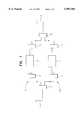
- FIG. 1is a block diagram of a repeater having amplifier chains provided with filter devices according to the invention.
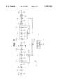
- FIG. 2is a more detailed block diagram of a controllable filter device according to the invention.
- the repeater shown in FIG. 1is basically of the kind disclosed in the document WO95/31866. It comprises a first antenna 1 for radio communication between the repeater and a cellular mobile telephone (not shown) and a second antenna 2 for a corresponding radio communication between the repeater and a base station (not shown).
- the RF-signals received by the first antenna 1are retransmitted, after amplification, by the second antenna 2 at the same (first) carrier frequency.
- the RF-signals received by the second antenna 2are retransmitted from the first antenna 1 at the same (second) carrier frequency.
- the first and second antennas 1, 2are connected via duplex filters 3, 13 to two oppositely directed links, namely an uplink 100 for transferring signals originating from mobile telephones towards the associated base station, and a downlink 200 for transferring signals in the opposite direction.
- the signals received by the first antenna 1are fed through the duplex filter 3 to a multicoupler amplifier 4, which distributes the signals through a number of parallel amplifier chains 6, and further via a combiner 12 and the duplex filter 13 to the second antenna 2.
- the signalsare fed from the second antenna 2 through the duplex filter 13, a multicoupler amplifier 14, a number of parallel amplifier chains 7, a combiner 5, and further via a duplex filter 3 to the first antenna 1.
- Each amplifier 6 and 7, respectively,is designed to pass through a specific frequency channel, the centre frequency and bandwidth of which are controllable in accordance with the present invention.
- FIG. 2A specific example of the amplifier chain 6 is shown in FIG. 2. It should be pointed out that the embodiment of FIG. 2 is illustrated schematically. Thus, FIG. 2 only contains those components which are essential to the present invention, whereas other components, such as possible attenuators, detectors and switching devices for monitoring or adjusting the repeater, e.g. in accordance with the co-pending patent application No. 9600842-0, are left out.
- the amplifier chain in FIG. 2includes a large number of amplifiers A1-A9, a number of down-mixers 20, 20a, 20b, a corresponding number of up-mixers 21a, 21b, 21 and a number of band pass filters 24a, 25, 24b, 26, 24c and 27.
- the carrier waveis radio frequent, e.g. in a frequency range around 1800 MHz.
- the signalis shifted down to an intermediate frequency IF1 of e.g. 200 MHz.
- the signalpasses through a band pass filter 24a, which is relatively broad, and a subsequent amplifier A2.
- the signalpasses through a first filter unit 10 defined by a centre frequency IF2 e.g. in the order of 80 MHz and a bandwidth of e.g. 15 MHz.
- the first band pass filter unitincludes a down-mixer 20a, an amplifier A3, a band pass filter 25, an amplifier A4 and an up-mixer 21a, the two mixers 20a, 21a being connected to a VCO (voltage controlled oscillator) 22, the latter being controlled by a frequency control unit 28.
- the signalupon being shifted back to the frequency range IF1 200 MHz, passes through a relatively broad band pass filter 24b and the amplifier A5.
- the signalpasses through a second band pass filter unit 11 with a relatively narrow bandwidth.
- the filter unit 11includes a down-mixer 20b, an amplifier A6, a band pass filter 26, an amplifier A7, and an up-mixer 21b, the mixers 20b and 21b being connected to a VCO 29, which is likewise controlled by the frequency control unit 28.
- the signalpasses through a relatively broad filter 24c and the amplifier A8 before it is shifted back to the radio frequency range RF in the up-mixer 21. Finally, the signal is passed through a radio frequency filter 27 and the amplifier A9.
- the mixers 20 and 21are connected to a VCO 23, also controlled by the frequency control unit 28.
- the band pass filters 25 and 26 of the two filter units 10 and 11are narrower than the other band pass filters 24a, 24b, 24c and 27. So, the overall bandwidth is primarily dependent on these two filters 25, 26. However, since the oscillators 22 and 29 are controllable, the frequency band entering the respective filter 25, 26 can be shifted upwards or downwards.
- the frequency band entering the fixed filter 25is shifted and will accordingly be cut off at its upper end and, upon arriving at the filter 26 and having been shifted down, it will be cut off at its lower end, so that the resulting frequency band leaving the filter unit 11 will be reduced by 4 MHz in bandwidth.
- the oscillators 22 and 29are shiftable in opposite directions so as to cut off both ends of the frequency band.
- the oscillatorsdo not have to be changed in synchronism in opposite directions.
- the crucial featureis that the two fixed filters 25 and 26 have at least partially overlapping pass bands and that the frequency band entering the respective filter can be shifted. In this way, the bandwidth of the resulting overlap pass band is variable, whereby the effective bandwidth of the amplifier chain is controllable.
- the frequency control unit 28may form a part of a more general control unit serving to control several different functions of the repeater.
- the control unitmay in turn be controlled manually on site or, preferably, electronically by remote control from an operation and monitoring centre.
Landscapes
- Engineering & Computer Science (AREA)
- Computer Networks & Wireless Communication (AREA)
- Signal Processing (AREA)
- Radio Relay Systems (AREA)
- Mobile Radio Communication Systems (AREA)
- Amplifiers (AREA)
- Reduction Or Emphasis Of Bandwidth Of Signals (AREA)
- Cable Transmission Systems, Equalization Of Radio And Reduction Of Echo (AREA)
- Inorganic Insulating Materials (AREA)
- Oscillators With Electromechanical Resonators (AREA)
Abstract
Description
Claims (6)
Applications Claiming Priority (2)
| Application Number | Priority Date | Filing Date | Title |
|---|---|---|---|
| SE9602161 | 1996-05-31 | ||
| SE9602161ASE510569C2 (en) | 1996-05-31 | 1996-05-31 | Variable bandwidth repeater |
Publications (1)
| Publication Number | Publication Date |
|---|---|
| US5987304Atrue US5987304A (en) | 1999-11-16 |
Family
ID=20402832
Family Applications (1)
| Application Number | Title | Priority Date | Filing Date |
|---|---|---|---|
| US08/865,940Expired - LifetimeUS5987304A (en) | 1996-05-31 | 1997-05-30 | Repeater with variable bandwidth |
Country Status (12)
| Country | Link |
|---|---|
| US (1) | US5987304A (en) |
| EP (1) | EP0894373B1 (en) |
| JP (1) | JP2000505263A (en) |
| KR (1) | KR100313486B1 (en) |
| AT (1) | ATE204106T1 (en) |
| AU (1) | AU722385B2 (en) |
| CA (1) | CA2256330C (en) |
| DE (2) | DE894373T1 (en) |
| ES (1) | ES2159138T3 (en) |
| NO (1) | NO316050B1 (en) |
| SE (1) | SE510569C2 (en) |
| WO (1) | WO1997045969A1 (en) |
Cited By (53)
| Publication number | Priority date | Publication date | Assignee | Title |
|---|---|---|---|---|
| US6178314B1 (en)* | 1997-06-27 | 2001-01-23 | Visteon Global Technologies, Inc. | Radio receiver with adaptive bandwidth controls at intermediate frequency and audio frequency sections |
| US6275678B1 (en)* | 1997-12-18 | 2001-08-14 | Societe Europeenne Des Satellites S.A. | Method and apparatus for determining an operating point of a non-linear amplifier of a communication channel |
| US20020004377A1 (en)* | 2000-05-30 | 2002-01-10 | Goran Snygg | Device and method for improved filtering in a radio receiver in the microwave range |
| US20020039885A1 (en)* | 1999-11-01 | 2002-04-04 | Haim Weissman | Split repeater |
| US20020045431A1 (en)* | 2000-10-18 | 2002-04-18 | Spotwave Wireless Inc. | Intelligent gain control in an on-frequency repeater |
| US20020090037A1 (en)* | 1998-12-23 | 2002-07-11 | Xiaoyun Hu | System and method for variable bandwidth transmission |
| US6484012B1 (en)* | 1997-08-04 | 2002-11-19 | Wireless Facilities, Inc. | Inter-band communication repeater system |
| US20040110469A1 (en)* | 2000-01-14 | 2004-06-10 | Judd Mano D. | Repeaters for wireless communication systems |
| KR100462713B1 (en)* | 2002-10-10 | 2004-12-23 | 현광전자통신 주식회사 | A frequency converting repeater with improved phase-noise feature |
| US20050282491A1 (en)* | 2004-06-03 | 2005-12-22 | Gainey Kenneth M | Frequency translating repeater with low cost high performance local oscillator architecture |
| US20060176777A1 (en)* | 2003-05-20 | 2006-08-10 | Takashi Ihara | Tuning device and radio-wave corrected timepiece |
| US20060189276A1 (en)* | 2004-12-08 | 2006-08-24 | Michael Halinski | Methods and systems for intelligent adaptive gain control |
| US20060205343A1 (en)* | 2005-03-11 | 2006-09-14 | Runyon Donald L | Wireless repeater with feedback suppression features |
| US20070066220A1 (en)* | 2004-05-13 | 2007-03-22 | Widefi, Inc. | Non-frequency translating repeater with downlink detection for uplink and downlink synchronization |
| US20070232228A1 (en)* | 2006-04-04 | 2007-10-04 | Mckay David L Sr | Wireless repeater with universal server base unit and modular donor antenna options |
| WO2007120011A1 (en)* | 2006-04-18 | 2007-10-25 | Posdata Co., Ltd. | Repeater interface unit and signal converting method thereof |
| US7299005B1 (en) | 2004-01-07 | 2007-11-20 | Sprint Spectrum L.P. | Radio frequency repeater with automated block/channel selection |
| US20070268846A1 (en)* | 2006-03-31 | 2007-11-22 | Widefi, Inc. | Enhanced physical layer repeater for operation in WiMAX systems |
| US20070286110A1 (en)* | 2002-10-24 | 2007-12-13 | Widefi, Inc. | Physical layer repeater with selective use of higher layer functions based on network operating conditions |
| US20080293360A1 (en)* | 2007-05-22 | 2008-11-27 | Nikolai Maslennikov | On frequency repeater with AGC stability determination |
| US7480485B1 (en) | 2004-01-07 | 2009-01-20 | Sprint Spectrum L.P. | Radio frequency repeater with automated block/channel selection |
| US20090111401A1 (en)* | 2007-10-29 | 2009-04-30 | Grigory Itkin | Transmitter arrangement |
| US7574230B1 (en)* | 2001-05-31 | 2009-08-11 | Sprint Spectrum L.P. | Remote base station with transmit power control |
| USRE40900E1 (en)* | 1999-05-22 | 2009-09-01 | Forster Ian J | Amplifier circuit |
| US7623866B1 (en) | 2006-07-10 | 2009-11-24 | Sprint Spectrum L.P. | Automatic generation of neighbor lists in a wireless network |
| US20100265839A1 (en)* | 2007-12-14 | 2010-10-21 | Telefonaktiebolaget Lm Ericsson (Publ) | Improved Radio Repeater Controllability |
| US7848758B1 (en) | 2005-09-27 | 2010-12-07 | Sprint Spectrum L.P. | Dynamic allocation of carrier frequencies in wireless wide area networks |
| US7990904B2 (en) | 2002-12-16 | 2011-08-02 | Qualcomm Incorporated | Wireless network repeater |
| US8027642B2 (en) | 2004-04-06 | 2011-09-27 | Qualcomm Incorporated | Transmission canceller for wireless local area network |
| US8060009B2 (en) | 2002-10-15 | 2011-11-15 | Qualcomm Incorporated | Wireless local area network repeater with automatic gain control for extending network coverage |
| US8059727B2 (en) | 2005-01-28 | 2011-11-15 | Qualcomm Incorporated | Physical layer repeater configuration for increasing MIMO performance |
| US8078100B2 (en) | 2002-10-15 | 2011-12-13 | Qualcomm Incorporated | Physical layer repeater with discrete time filter for all-digital detection and delay generation |
| US20120007693A1 (en)* | 2008-10-24 | 2012-01-12 | Silicon Laboratories Inc. | Dual in-situ mixing for extended tuning range of resonators |
| US8111645B2 (en) | 2002-11-15 | 2012-02-07 | Qualcomm Incorporated | Wireless local area network repeater with detection |
| US8122134B2 (en) | 2002-10-11 | 2012-02-21 | Qualcomm Incorporated | Reducing loop effects in a wireless local area network repeater |
| US20120164939A1 (en)* | 2009-06-12 | 2012-06-28 | Ntt Docomo, Inc. | Repeater equipment |
| US8320313B1 (en) | 2009-06-19 | 2012-11-27 | Sprint Spectrum L.P. | Method and system for carrier frequency management based on slot contention |
| US8325648B1 (en) | 2009-04-29 | 2012-12-04 | Sprint Spectrum L.P. | Methods and systems for assigning a wireless communication device to a carrier frequency |
| US20130039229A1 (en)* | 2011-08-12 | 2013-02-14 | Chester Park | Frontend module for time division duplex (tdd) carrier aggregation |
| US8498241B1 (en) | 2009-03-10 | 2013-07-30 | Sprint Spectrum L.P. | Use of macro-network channel-list messages for selection of carriers for low-cost internet base-station frequency-hopping pilot beacons |
| US8498234B2 (en) | 2002-06-21 | 2013-07-30 | Qualcomm Incorporated | Wireless local area network repeater |
| US8559379B2 (en) | 2006-09-21 | 2013-10-15 | Qualcomm Incorporated | Method and apparatus for mitigating oscillation between repeaters |
| WO2014058374A1 (en) | 2012-10-11 | 2014-04-17 | Telefonaktiebolaget L M Ericsson (Publ) | Filter apparatus, multiplex device and associated method |
| US20140105203A1 (en)* | 2012-10-11 | 2014-04-17 | Telefonaktiebolaget L M Ericsson (Publ) | Filter Apparatus, Multiplex Device and Associated Method |
| US8774079B2 (en) | 2006-10-26 | 2014-07-08 | Qualcomm Incorporated | Repeater techniques for multiple input multiple output utilizing beam formers |
| US8798013B1 (en) | 2011-03-25 | 2014-08-05 | Sprint Spectrum L.P. | Method and system for management of data transmission in timeslots |
| US8885688B2 (en) | 2002-10-01 | 2014-11-11 | Qualcomm Incorporated | Control message management in physical layer repeater |
| US9107148B1 (en) | 2009-11-30 | 2015-08-11 | Sprint Spectrum L.P. | Use of pre-handoff macro-carrier data for prioritization of carriers in femtocell frequency-hopping pilot beacons |
| US20160134355A1 (en)* | 2014-11-07 | 2016-05-12 | Nextivity, Inc. | System and method for selecting an operator to boost in a repeater |
| US9660720B2 (en) | 2008-07-10 | 2017-05-23 | Telefonaktiebolaget Lm Ericsson (Publ) | Self-optimizing repeater |
| US20180331752A1 (en)* | 2017-05-11 | 2018-11-15 | Wilson Electronics, Llc | Variable channelized bandwidth booster |
| CN109792288A (en)* | 2016-09-23 | 2019-05-21 | 威尔逊电子有限责任公司 | Booster with integrated global position system module |
| US11757482B2 (en)* | 2018-03-15 | 2023-09-12 | Murata Manufacturing Co., Ltd. | Frontend circuit, frontend module, communication apparatus, and multiplexer |
Families Citing this family (4)
| Publication number | Priority date | Publication date | Assignee | Title |
|---|---|---|---|---|
| JP5261787B2 (en)* | 2008-03-07 | 2013-08-14 | 三洋電機株式会社 | Receiving apparatus and receiving method |
| KR100931861B1 (en)* | 2009-05-19 | 2009-12-15 | 주식회사 위다스 | Repeater control method and device using system identification information |
| JP2011055218A (en)* | 2009-09-01 | 2011-03-17 | Systec:Kk | Position associated radio relay device, and spot information relay system |
| EP2629433A1 (en) | 2012-02-16 | 2013-08-21 | Astrium Limited | Signal conversion in communications satellites |
Citations (11)
| Publication number | Priority date | Publication date | Assignee | Title |
|---|---|---|---|---|
| US3922674A (en)* | 1974-01-24 | 1975-11-25 | Raytheon Co | Transponder for use in a radio frequency communication system |
| US4160212A (en)* | 1977-05-26 | 1979-07-03 | Raytheon Company | Radio frequency receiver having serially coupled heterodyning stages, each stage having filters with difference center frequencies |
| US4228401A (en)* | 1977-12-22 | 1980-10-14 | Communications Satellite Corporation | Communication satellite transponder interconnection utilizing variable bandpass filter |
| US4764979A (en)* | 1983-02-10 | 1988-08-16 | Fujitsu Limited | Direct relay equipment |
| US4783843A (en)* | 1986-05-23 | 1988-11-08 | Peninsula Engineering Group, Inc. | Split band filter for cellular mobile radio |
| US4972346A (en)* | 1987-03-24 | 1990-11-20 | Mitsubishi Denki Kabushiki Kaisha | High-frequency signal booster |
| US5136267A (en)* | 1990-12-26 | 1992-08-04 | Audio Precision, Inc. | Tunable bandpass filter system and filtering method |
| US5408681A (en)* | 1993-08-16 | 1995-04-18 | The United States Of America As Represented By The Secretary Of The Navy | Automatic repeater station for signal transmissions |
| WO1995031866A1 (en)* | 1994-05-11 | 1995-11-23 | Allgon Ab | Repeater |
| US5594939A (en)* | 1992-11-23 | 1997-01-14 | Hughes Aircraft Company | Synthesizer routing architecture for a switching apparatus |
| US5768685A (en)* | 1995-12-11 | 1998-06-16 | Hughes Electronics | Method and apparatus for converting signals in a base station receiver |
- 1996
- 1996-05-31SESE9602161Apatent/SE510569C2/ennot_activeIP Right Cessation
- 1997
- 1997-05-28JPJP9542228Apatent/JP2000505263A/enactivePending
- 1997-05-28ATAT97926327Tpatent/ATE204106T1/enactive
- 1997-05-28WOPCT/SE1997/000916patent/WO1997045969A1/enactiveIP Right Grant
- 1997-05-28KRKR1019980709762Apatent/KR100313486B1/ennot_activeExpired - Lifetime
- 1997-05-28ESES97926327Tpatent/ES2159138T3/ennot_activeExpired - Lifetime
- 1997-05-28DEDE0894373Tpatent/DE894373T1/enactivePending
- 1997-05-28CACA002256330Apatent/CA2256330C/ennot_activeExpired - Lifetime
- 1997-05-28DEDE69706044Tpatent/DE69706044T2/ennot_activeExpired - Lifetime
- 1997-05-28AUAU31116/97Apatent/AU722385B2/ennot_activeExpired
- 1997-05-28EPEP97926327Apatent/EP0894373B1/ennot_activeRevoked
- 1997-05-30USUS08/865,940patent/US5987304A/ennot_activeExpired - Lifetime
- 1998
- 1998-11-26NONO985514Apatent/NO316050B1/ennot_activeIP Right Cessation
Patent Citations (12)
| Publication number | Priority date | Publication date | Assignee | Title |
|---|---|---|---|---|
| US3922674A (en)* | 1974-01-24 | 1975-11-25 | Raytheon Co | Transponder for use in a radio frequency communication system |
| US4160212A (en)* | 1977-05-26 | 1979-07-03 | Raytheon Company | Radio frequency receiver having serially coupled heterodyning stages, each stage having filters with difference center frequencies |
| US4228401A (en)* | 1977-12-22 | 1980-10-14 | Communications Satellite Corporation | Communication satellite transponder interconnection utilizing variable bandpass filter |
| US4764979A (en)* | 1983-02-10 | 1988-08-16 | Fujitsu Limited | Direct relay equipment |
| US4783843A (en)* | 1986-05-23 | 1988-11-08 | Peninsula Engineering Group, Inc. | Split band filter for cellular mobile radio |
| US4972346A (en)* | 1987-03-24 | 1990-11-20 | Mitsubishi Denki Kabushiki Kaisha | High-frequency signal booster |
| US5136267A (en)* | 1990-12-26 | 1992-08-04 | Audio Precision, Inc. | Tunable bandpass filter system and filtering method |
| US5594939A (en)* | 1992-11-23 | 1997-01-14 | Hughes Aircraft Company | Synthesizer routing architecture for a switching apparatus |
| US5408681A (en)* | 1993-08-16 | 1995-04-18 | The United States Of America As Represented By The Secretary Of The Navy | Automatic repeater station for signal transmissions |
| WO1995031866A1 (en)* | 1994-05-11 | 1995-11-23 | Allgon Ab | Repeater |
| US5809398A (en)* | 1994-05-11 | 1998-09-15 | Allgon Ab | Channel selective repeater |
| US5768685A (en)* | 1995-12-11 | 1998-06-16 | Hughes Electronics | Method and apparatus for converting signals in a base station receiver |
Cited By (78)
| Publication number | Priority date | Publication date | Assignee | Title |
|---|---|---|---|---|
| US6178314B1 (en)* | 1997-06-27 | 2001-01-23 | Visteon Global Technologies, Inc. | Radio receiver with adaptive bandwidth controls at intermediate frequency and audio frequency sections |
| US6684058B1 (en)* | 1997-08-04 | 2004-01-27 | Wireless Facilities, Inc. | Universal repeater for communication systems |
| US6484012B1 (en)* | 1997-08-04 | 2002-11-19 | Wireless Facilities, Inc. | Inter-band communication repeater system |
| US6275678B1 (en)* | 1997-12-18 | 2001-08-14 | Societe Europeenne Des Satellites S.A. | Method and apparatus for determining an operating point of a non-linear amplifier of a communication channel |
| US20020090037A1 (en)* | 1998-12-23 | 2002-07-11 | Xiaoyun Hu | System and method for variable bandwidth transmission |
| USRE40900E1 (en)* | 1999-05-22 | 2009-09-01 | Forster Ian J | Amplifier circuit |
| US8358970B2 (en) | 1999-07-20 | 2013-01-22 | Andrew Corporation | Repeaters for wireless communication systems |
| US8630581B2 (en) | 1999-07-20 | 2014-01-14 | Andrew Llc | Repeaters for wireless communication systems |
| US8971796B2 (en) | 1999-07-20 | 2015-03-03 | Andrew Llc | Repeaters for wireless communication systems |
| US20020039885A1 (en)* | 1999-11-01 | 2002-04-04 | Haim Weissman | Split repeater |
| US20040110469A1 (en)* | 2000-01-14 | 2004-06-10 | Judd Mano D. | Repeaters for wireless communication systems |
| US7577398B2 (en) | 2000-01-14 | 2009-08-18 | Andrew Llc | Repeaters for wireless communication systems |
| US20020004377A1 (en)* | 2000-05-30 | 2002-01-10 | Goran Snygg | Device and method for improved filtering in a radio receiver in the microwave range |
| US6889033B2 (en)* | 2000-10-18 | 2005-05-03 | Spotwave Wireless Inc. | Intelligent gain control in an on-frequency repeater |
| US20020045431A1 (en)* | 2000-10-18 | 2002-04-18 | Spotwave Wireless Inc. | Intelligent gain control in an on-frequency repeater |
| US7574230B1 (en)* | 2001-05-31 | 2009-08-11 | Sprint Spectrum L.P. | Remote base station with transmit power control |
| US8498234B2 (en) | 2002-06-21 | 2013-07-30 | Qualcomm Incorporated | Wireless local area network repeater |
| US8885688B2 (en) | 2002-10-01 | 2014-11-11 | Qualcomm Incorporated | Control message management in physical layer repeater |
| KR100462713B1 (en)* | 2002-10-10 | 2004-12-23 | 현광전자통신 주식회사 | A frequency converting repeater with improved phase-noise feature |
| US8122134B2 (en) | 2002-10-11 | 2012-02-21 | Qualcomm Incorporated | Reducing loop effects in a wireless local area network repeater |
| US8060009B2 (en) | 2002-10-15 | 2011-11-15 | Qualcomm Incorporated | Wireless local area network repeater with automatic gain control for extending network coverage |
| US8078100B2 (en) | 2002-10-15 | 2011-12-13 | Qualcomm Incorporated | Physical layer repeater with discrete time filter for all-digital detection and delay generation |
| US20070286110A1 (en)* | 2002-10-24 | 2007-12-13 | Widefi, Inc. | Physical layer repeater with selective use of higher layer functions based on network operating conditions |
| US8089913B2 (en) | 2002-10-24 | 2012-01-03 | Qualcomm Incorporated | Physical layer repeater with selective use of higher layer functions based on network operating conditions |
| US8111645B2 (en) | 2002-11-15 | 2012-02-07 | Qualcomm Incorporated | Wireless local area network repeater with detection |
| US7990904B2 (en) | 2002-12-16 | 2011-08-02 | Qualcomm Incorporated | Wireless network repeater |
| US20060176777A1 (en)* | 2003-05-20 | 2006-08-10 | Takashi Ihara | Tuning device and radio-wave corrected timepiece |
| US7583942B2 (en)* | 2003-05-20 | 2009-09-01 | Citizen Holdings Co., Ltd. | Tuning device and radio-wave corrected timepiece |
| US7480485B1 (en) | 2004-01-07 | 2009-01-20 | Sprint Spectrum L.P. | Radio frequency repeater with automated block/channel selection |
| US7299005B1 (en) | 2004-01-07 | 2007-11-20 | Sprint Spectrum L.P. | Radio frequency repeater with automated block/channel selection |
| US8027642B2 (en) | 2004-04-06 | 2011-09-27 | Qualcomm Incorporated | Transmission canceller for wireless local area network |
| US8023885B2 (en) | 2004-05-13 | 2011-09-20 | Qualcomm Incorporated | Non-frequency translating repeater with downlink detection for uplink and downlink synchronization |
| US20070066220A1 (en)* | 2004-05-13 | 2007-03-22 | Widefi, Inc. | Non-frequency translating repeater with downlink detection for uplink and downlink synchronization |
| US8095067B2 (en) | 2004-06-03 | 2012-01-10 | Qualcomm Incorporated | Frequency translating repeater with low cost high performance local oscillator architecture |
| US20050282491A1 (en)* | 2004-06-03 | 2005-12-22 | Gainey Kenneth M | Frequency translating repeater with low cost high performance local oscillator architecture |
| US7187904B2 (en)* | 2004-06-03 | 2007-03-06 | Widefi, Inc. | Frequency translating repeater with low cost high performance local oscillator architecture |
| US20060189276A1 (en)* | 2004-12-08 | 2006-08-24 | Michael Halinski | Methods and systems for intelligent adaptive gain control |
| US8059727B2 (en) | 2005-01-28 | 2011-11-15 | Qualcomm Incorporated | Physical layer repeater configuration for increasing MIMO performance |
| US20060205343A1 (en)* | 2005-03-11 | 2006-09-14 | Runyon Donald L | Wireless repeater with feedback suppression features |
| US20060205341A1 (en)* | 2005-03-11 | 2006-09-14 | Ems Technologies, Inc. | Dual polarization wireless repeater including antenna elements with balanced and quasi-balanced feeds |
| US7848758B1 (en) | 2005-09-27 | 2010-12-07 | Sprint Spectrum L.P. | Dynamic allocation of carrier frequencies in wireless wide area networks |
| US20070268846A1 (en)* | 2006-03-31 | 2007-11-22 | Widefi, Inc. | Enhanced physical layer repeater for operation in WiMAX systems |
| US20070232228A1 (en)* | 2006-04-04 | 2007-10-04 | Mckay David L Sr | Wireless repeater with universal server base unit and modular donor antenna options |
| WO2007120011A1 (en)* | 2006-04-18 | 2007-10-25 | Posdata Co., Ltd. | Repeater interface unit and signal converting method thereof |
| US20100227548A1 (en)* | 2006-04-18 | 2010-09-09 | Posdata Co., Ltd | Repeater interface unit and signal converting method thereof |
| US7623866B1 (en) | 2006-07-10 | 2009-11-24 | Sprint Spectrum L.P. | Automatic generation of neighbor lists in a wireless network |
| US8559379B2 (en) | 2006-09-21 | 2013-10-15 | Qualcomm Incorporated | Method and apparatus for mitigating oscillation between repeaters |
| US8774079B2 (en) | 2006-10-26 | 2014-07-08 | Qualcomm Incorporated | Repeater techniques for multiple input multiple output utilizing beam formers |
| WO2008147506A1 (en) | 2007-05-22 | 2008-12-04 | Powerwave Technologies, Inc. | On frequency repeater with agc stability determination |
| US20080293360A1 (en)* | 2007-05-22 | 2008-11-27 | Nikolai Maslennikov | On frequency repeater with AGC stability determination |
| US8073387B2 (en) | 2007-05-22 | 2011-12-06 | Powerwave Technologies, Inc. | On frequency repeater with AGC stability determination |
| US7853290B2 (en) | 2007-10-29 | 2010-12-14 | Infineon Technologies Ag | Transmitter arrangement |
| US20090111401A1 (en)* | 2007-10-29 | 2009-04-30 | Grigory Itkin | Transmitter arrangement |
| US20100265839A1 (en)* | 2007-12-14 | 2010-10-21 | Telefonaktiebolaget Lm Ericsson (Publ) | Improved Radio Repeater Controllability |
| US9496945B2 (en) | 2007-12-14 | 2016-11-15 | Telefonaktiebolaget Lm Ericsson (Publ) | Radio repeater controllability |
| US9660720B2 (en) | 2008-07-10 | 2017-05-23 | Telefonaktiebolaget Lm Ericsson (Publ) | Self-optimizing repeater |
| US8456252B2 (en)* | 2008-10-24 | 2013-06-04 | Silicon Laboratories Inc. | Dual in-situ mixing for extended tuning range of resonators |
| US20120007693A1 (en)* | 2008-10-24 | 2012-01-12 | Silicon Laboratories Inc. | Dual in-situ mixing for extended tuning range of resonators |
| US8498241B1 (en) | 2009-03-10 | 2013-07-30 | Sprint Spectrum L.P. | Use of macro-network channel-list messages for selection of carriers for low-cost internet base-station frequency-hopping pilot beacons |
| US8325648B1 (en) | 2009-04-29 | 2012-12-04 | Sprint Spectrum L.P. | Methods and systems for assigning a wireless communication device to a carrier frequency |
| US20120164939A1 (en)* | 2009-06-12 | 2012-06-28 | Ntt Docomo, Inc. | Repeater equipment |
| US8320313B1 (en) | 2009-06-19 | 2012-11-27 | Sprint Spectrum L.P. | Method and system for carrier frequency management based on slot contention |
| US9107148B1 (en) | 2009-11-30 | 2015-08-11 | Sprint Spectrum L.P. | Use of pre-handoff macro-carrier data for prioritization of carriers in femtocell frequency-hopping pilot beacons |
| US8798013B1 (en) | 2011-03-25 | 2014-08-05 | Sprint Spectrum L.P. | Method and system for management of data transmission in timeslots |
| US20130039229A1 (en)* | 2011-08-12 | 2013-02-14 | Chester Park | Frontend module for time division duplex (tdd) carrier aggregation |
| US8737376B2 (en)* | 2011-08-12 | 2014-05-27 | Telefonaktiebolaget L M Ericsson (Publ) | Frontend module for time division duplex (TDD) carrier aggregation |
| US20140105203A1 (en)* | 2012-10-11 | 2014-04-17 | Telefonaktiebolaget L M Ericsson (Publ) | Filter Apparatus, Multiplex Device and Associated Method |
| US9337947B2 (en)* | 2012-10-11 | 2016-05-10 | Telefonaktiebolaget L M Ericsson (Publ) | Filter apparatus, multiplex device and associated method |
| WO2014058374A1 (en) | 2012-10-11 | 2014-04-17 | Telefonaktiebolaget L M Ericsson (Publ) | Filter apparatus, multiplex device and associated method |
| US20160134355A1 (en)* | 2014-11-07 | 2016-05-12 | Nextivity, Inc. | System and method for selecting an operator to boost in a repeater |
| US9780863B2 (en)* | 2014-11-07 | 2017-10-03 | Nextivity, Inc. | System and method for selecting an operator to boost in a repeater |
| CN109792288A (en)* | 2016-09-23 | 2019-05-21 | 威尔逊电子有限责任公司 | Booster with integrated global position system module |
| EP3516789A4 (en)* | 2016-09-23 | 2020-05-06 | Wilson Electronics, LLC | Booster with an integrated satellite location system module |
| US20180331752A1 (en)* | 2017-05-11 | 2018-11-15 | Wilson Electronics, Llc | Variable channelized bandwidth booster |
| US10523305B2 (en)* | 2017-05-11 | 2019-12-31 | Wilson Electronics, Llc | Variable channelized bandwidth booster |
| US11757482B2 (en)* | 2018-03-15 | 2023-09-12 | Murata Manufacturing Co., Ltd. | Frontend circuit, frontend module, communication apparatus, and multiplexer |
| US20230370105A1 (en)* | 2018-03-15 | 2023-11-16 | Murata Manufacturing Co., Ltd. | Frontend circuit, frontend module, communication apparatus, and multiplexer |
| US12375116B2 (en)* | 2018-03-15 | 2025-07-29 | Murata Manufacturing Co., Ltd. | Frontend circuit, frontend module, communication apparatus, and multiplexer |
Also Published As
| Publication number | Publication date |
|---|---|
| ATE204106T1 (en) | 2001-08-15 |
| DE69706044D1 (en) | 2001-09-13 |
| JP2000505263A (en) | 2000-04-25 |
| CA2256330C (en) | 2004-01-27 |
| CA2256330A1 (en) | 1997-12-04 |
| WO1997045969A1 (en) | 1997-12-04 |
| DE894373T1 (en) | 2000-06-08 |
| EP0894373B1 (en) | 2001-08-08 |
| AU3111697A (en) | 1998-01-05 |
| ES2159138T3 (en) | 2001-09-16 |
| DE69706044T2 (en) | 2002-03-21 |
| SE510569C2 (en) | 1999-06-07 |
| NO316050B1 (en) | 2003-12-01 |
| SE9602161D0 (en) | 1996-05-31 |
| AU722385B2 (en) | 2000-08-03 |
| NO985514L (en) | 1998-11-26 |
| NO985514D0 (en) | 1998-11-26 |
| KR100313486B1 (en) | 2001-12-31 |
| SE9602161L (en) | 1997-12-01 |
| KR20000016194A (en) | 2000-03-25 |
| EP0894373A1 (en) | 1999-02-03 |
Similar Documents
| Publication | Publication Date | Title |
|---|---|---|
| US5987304A (en) | Repeater with variable bandwidth | |
| US5953670A (en) | Arrangement for providing cellular communication via a CATV network | |
| EP0468688B1 (en) | Method and apparatus for providing wireless communications between remote locations | |
| US12224837B2 (en) | Systems and methods for reconfigurable repeaters for wireless telecommunications | |
| US20020123306A1 (en) | Channelized booster amplifier for cellular communications | |
| JP2002171194A (en) | Wireless device, portable information terminal and wireless base station including the same, and wireless communication system including them | |
| CN1132579A (en) | Base Station Equipment Using Diversity Reception | |
| US10886964B2 (en) | Non-duplexer architectures for telecommunications system | |
| EP1243147B1 (en) | Base station with a first and a second base unit | |
| US6317610B1 (en) | Method of combining several signals, and base station | |
| EP0692163B1 (en) | Radio repeater | |
| JP2981259B2 (en) | Same frequency radio repeater | |
| JP2950676B2 (en) | Wireless relay device | |
| JP3095126B2 (en) | Mobile radio frequency selective repeater | |
| JP3301469B2 (en) | Signal transmission equipment | |
| KR20010060268A (en) | Transmitting/receiving apparatus for electromagnetic signals | |
| JPH09205464A (en) | Digital radio | |
| CA2001308A1 (en) | Short range multi-channel microwave transmitter | |
| GB2389258A (en) | Filter arrangement in a multi-band mobile terminal device | |
| JPH07274244A (en) | Pass band changeover circuit in radio telephone system | |
| JPS6342449B2 (en) | ||
| JPS6313529A (en) | Transmitter-receiver for radio telephony | |
| JPH03274825A (en) | Radio communication equipment | |
| JPH0744478B2 (en) | Receiver |
Legal Events
| Date | Code | Title | Description |
|---|---|---|---|
| AS | Assignment | Owner name:ALLGON AB, SWEDEN Free format text:ASSIGNMENT OF ASSIGNORS INTEREST;ASSIGNOR:LATT, MIKAEL;REEL/FRAME:008954/0413 Effective date:19970513 | |
| STCF | Information on status: patent grant | Free format text:PATENTED CASE | |
| FEPP | Fee payment procedure | Free format text:PAYOR NUMBER ASSIGNED (ORIGINAL EVENT CODE: ASPN); ENTITY STATUS OF PATENT OWNER: LARGE ENTITY | |
| FPAY | Fee payment | Year of fee payment:4 | |
| REMI | Maintenance fee reminder mailed | ||
| FPAY | Fee payment | Year of fee payment:8 | |
| FPAY | Fee payment | Year of fee payment:12 | |
| AS | Assignment | Owner name:P-WAVE HOLDINGS, LLC, CALIFORNIA Free format text:SECURITY AGREEMENT;ASSIGNOR:POWERWAVE TECHNOLOGIES, INC.;REEL/FRAME:028939/0381 Effective date:20120911 | |
| AS | Assignment | Owner name:POWERWAVE TECHNOLOGIES, INC., CALIFORNIA Free format text:ASSIGNMENT OF ASSIGNORS INTEREST;ASSIGNOR:POWERWAVE TECHNOLOGIES SWEDEN AB;REEL/FRAME:031925/0237 Effective date:20130508 Owner name:P-WAVE HOLDINGS, LLC, CALIFORNIA Free format text:ASSIGNMENT OF ASSIGNORS INTEREST;ASSIGNOR:POWERWAVE TECHNOLOGIES, INC.;REEL/FRAME:031925/0252 Effective date:20130522 | |
| AS | Assignment | Owner name:POWERWAVE TECHNOLOGIES S.A.R.L., LUXEMBOURG Free format text:ASSIGNMENT OF ASSIGNORS INTEREST;ASSIGNOR:P-WAVE HOLDINGS, LLC;REEL/FRAME:032366/0432 Effective date:20140220 | |
| AS | Assignment | Owner name:POWERWAVE SWEDEN AB, SWEDEN Free format text:CHANGE OF NAME;ASSIGNOR:ALLGON AB;REEL/FRAME:032422/0253 Effective date:20041115 Owner name:POWERWAVE TECHNOLOGIES SWEDEN AB, SWEDEN Free format text:ASSIGNMENT OF ASSIGNORS INTEREST;ASSIGNOR:POWERWAVE SWEDEN AB;REEL/FRAME:032392/0094 Effective date:20081103 | |
| AS | Assignment | Owner name:INTEL CORPORATION, CALIFORNIA Free format text:ASSIGNMENT OF ASSIGNORS INTEREST;ASSIGNOR:POWERWAVE TECHNOLOGIES S.A.R.L.;REEL/FRAME:034216/0001 Effective date:20140827 | |
| AS | Assignment | Owner name:POWERWAVE TECHNOLOGIES S.A.R.L., LUXEMBOURG Free format text:CORRECTIVE ASSIGNMENT TO CORRECT THE LIST OF PATENTS ASSIGNED TO REMOVE US PATENT NO. 6617817 PREVIOUSLY RECORDED ON REEL 032366 FRAME 0432. ASSIGNOR(S) HEREBY CONFIRMS THE ASSIGNMENT OF RIGHTS IN THE REMAINING ITEMS TO THE NAMED ASSIGNEE;ASSIGNOR:P-WAVE HOLDINGS, LLC;REEL/FRAME:034429/0889 Effective date:20140220 | |
| FEPP | Fee payment procedure | Free format text:PAYOR NUMBER ASSIGNED (ORIGINAL EVENT CODE: ASPN); ENTITY STATUS OF PATENT OWNER: LARGE ENTITY Free format text:PAYER NUMBER DE-ASSIGNED (ORIGINAL EVENT CODE: RMPN); ENTITY STATUS OF PATENT OWNER: LARGE ENTITY |