US5987189A - Method of combining multiple sets of overlapping surface-profile interferometric data to produce a continuous composite map - Google Patents
Method of combining multiple sets of overlapping surface-profile interferometric data to produce a continuous composite mapDownload PDFInfo
- Publication number
- US5987189A US5987189AUS08/771,428US77142896AUS5987189AUS 5987189 AUS5987189 AUS 5987189AUS 77142896 AUS77142896 AUS 77142896AUS 5987189 AUS5987189 AUS 5987189A
- Authority
- US
- United States
- Prior art keywords
- section
- profile
- measured
- region
- height
- Prior art date
- Legal status (The legal status is an assumption and is not a legal conclusion. Google has not performed a legal analysis and makes no representation as to the accuracy of the status listed.)
- Expired - Lifetime
Links
Images


Classifications
- G—PHYSICS
- G06—COMPUTING OR CALCULATING; COUNTING
- G06T—IMAGE DATA PROCESSING OR GENERATION, IN GENERAL
- G06T11/00—2D [Two Dimensional] image generation
Definitions
- This inventionpertains to the general field of interferometric profilometry.
- itprovides a technique for improving the resolution of an interferometric profilometer by reducing the field of view of its objective and combining multiple overlapping images to form a composite profile.
- the optical resolution of the objective of an interferometeris an important parameter in the overall performance of the instrument.
- the spatial resolutioncan be enhanced by reducing the field of view of the objective, but that also reduces the capability of the instrument with respect to the area of sample being tested. If, on the other hand, the field of view is enlarged to cover a larger test surface, the optical (and therefore also spatial) resolution of the resulting image is adversely affected. Therefore, a practical balance is normally struck between the optical resolution of the profilometer and the size of the test surface that it can handle.
- This inventionprovides a procedure for enhancing the resolution or, alternatively, for increasing the x-y profiling range of a conventional interferometer.
- Another object of the inventionis a procedure for increasing the field of view of a given interferometric profiler without affecting its optical resolution.
- Another objective of the inventionis a computationally efficient method to achieve the above goals, so that computer processing time is minimized.
- Another goal of the inventionis a method that is computationally stable, repeatable and consistent with measured data.
- a further objective of the inventionis a procedure capable of implementation in real time for on-line applications.
- Another goal of the inventionis its general application to increasing the x-y scanning range of conventional interferometric profilers without limitation to any specific field of testing.
- Another goalis the realization of the above mentioned objectives in a system that can be implemented with existing sensory, computing, and other hardware devices.
- the preferred embodiment of the method and apparatus of this inventionconsists of taking successive measurements of adjacent sections of the surface of a test sample by sequentially placing them within the field of view of the instrument and independently profiling each section by phase shifting or vertical scanning interferometry.
- the x-y translation of the microscope between successive measurements from one section to the next adjacent section of the surface being profiledis carried out by maintaining a region of overlap between sections, so that spatial continuity is retained between measurements.
- the height data generated for each sectionare then combined to form a larger image corresponding to the entire surface tested and discontinuities and/or errors introduced by the x-y translation process are corrected by normalizing the overlapping portions to a common reference plane.
- a planeis fitted through each set of measured heights in the overlapping regions and the tip, tilt and offset of one of the fitted planes are corrected to produce matching overlapping height data in adjacent sections.
- the measured height data for the balance of each sectionare then also corrected by the same difference in tip, tilt and offset to obtain a continuous normalized image.
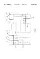
- FIG. 1illustrates in schematic view a test surface being measured by interferometric apparatus having an optical objective with a field of view smaller than the test surface, where the field of view is shown subdivided into rows and columns defining pixels corresponding to the cells of the light detector.
- FIG. 2illustrates the steps of the invention related to the x-y translation of the objective to measure multiple overlapping sections of the test surface.
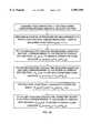
- FIG. 3is a block diagram of the process of the invention.
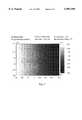
- FIG. 4is a first VSI measurement taken with a field of view corresponding to a magnification of 1.5 ⁇ , with a pixel spacing of 5.60 ⁇ m, of the first half of the pattern (E PLUR UNU) on a coin.
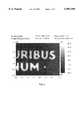
- FIG. 5is a second measurement taken with a field of view corresponding to a magnification of 1.5 ⁇ , with a pixel spacing of 5.60 ⁇ m, of the second half of the pattern (URIBUS NUM), where a predetermined tilt is introduced so that the two measurements do not fall into the same plane.
- FIG. 6is another measurement of the region of FIG. 5, but with the tilt removed, thereby approximating the tilt plane of the first measurement (FIG. 4) and the profile expected for this region after the corrections provided by the invention.
- FIG. 7is a composite profile obtained combining the data from the first and second measurements (FIGS. 4 and 5) according to the invention.
- FIG. 8is a profile corresponding to the coin of FIG. 7, but taken with a larger field of view, sufficient to span the entire image without a necessity for x-y translation.
- the method of this inventionis directed at optimizing the meshing of overlapping height-profile data acquired by interferometric measurements carried out according to conventional procedures and apparatus.
- the combination of such sets of data to form a larger composite image corresponding to the entire surfaceis complicated by the need for correction of misalignments and corresponding errors introduced during the x-y translation of the scanning mechanism in the interferometer.
- These misalignmentsresult in height data sets based on different reference planes; therefore, the overlapping portions of adjacent sections do not normally produce consistent height data.
- This inventiondescribes a process for normalizing the data to a common reference surface, such that the heights measured for overlapping portions of adjacent sections are equalized and all data sets may be combined to form an accurate composite profile.
- x, y and z orthogonal coordinateswherein x and y define a horizontal plane substantially parallel to the surface of the sample being tested and z defines a vertical direction of white-light (VSI) or phase-shifting (PSI) scanning, but it is obvious that the structure and operation of the features detailed herein could be rotated in any direction with equivalent results.
- VSIwhite-light
- PSIphase-shifting
- reference to x-y translationcorresponds to the very fine movement (on the order of several microns or millimeters, with control within less than 1 ⁇ m) of the optics of the interferometer in the plane of the test surface to position the optics over the desired target area on the surface of the sample, which is a very exact operation that requires precision instrumentation and mechanisms.
- the section of surface being testedis subdivided into an array of pixels corresponding to detector cells in the sensory apparatus.
- an array of height datais generated wherein each data point represents the height of a small region or pixel of a two-dimensional target area.
- the data arrayconstitutes a map of the height as measured at each pixel throughout the target area.
- FIG. 1illustrates in schematic view a test surface 10 being measured by interferometric apparatus having optics set with a field of view (smaller than the surface 10) equal to the area 12 subdivided into r rows and n columns (for example) of individual pixels 14.
- the objective of the interferometeris positioned over a predetermined first section 1 of the surface 10 at known x-y coordinates, as illustrated in FIG.
- H 1 (x,y)⁇ h 1 (1,1), h 1 (1,2), h 1 (1,3), . . . h 1 (r,s) ⁇ according to conventional interferometric procedures. It is noted that all such procedures involve the adjustment and measurement of the tip and tilt of the tested surface with respect to a predetermined reference plane, so that the measured height profile is relative to that plane.
- the objective of the interferometeris then translated in the x-y plane to a different section 2 of known x-y coordinates.
- the new coordinatesare selected to provide a region 16 of overlap with the first section 1.
- the overlap 16is illustrated in FIG. 2 as at least two columns, but differently-shaped common regions would be equivalently suitable to practice the invention.
- the particular geometry of the overlapping regionwould preferably depend on the arrangement of the pixels (normally an x-y array) in the light detecting apparatus.
- the critical considerationis that the region of overlap must be such as to provide sufficient data points to fit a plane equation through them.
- the procedureis repeated to cover the entire surface 10 intended for testing.
- the new positionis selected according to predetermined coordinates that ensure an overlap region with at least one adjacent section (such as two rows or two columns, as applicable; note that one row and one column with two adjacent sections would also suffice because of adequate data to fit a plane equation through them).
- the illustration of FIG. 2shows row overlaps 18 as well as column overlaps 16, but the exact nature and extent of the overlaps is not critical to the invention, so long as the exact pixels (i.e., exact x-y coordinates) corresponding to overlapping regions between pairs of measured sections are exactly known (within a spatial tolerance deemed acceptable).
- FIG. 2shows t sets of measurements for illustration purposes. Accordingly, the example of FIG. 2 would produce t sets of height data [H 1 (x,y) through H t (x,y)].
- the heart of the present inventionconcerns the process of normalizing and combining these height data to produce a smooth and accurate composite profile. Therefore, according to another aspect of the invention, the height data of overlapping regions of each pair of adjacent sections are fitted by conventional numerical methods (such as least squares) to produce plane functions representing each overlapping region.
- the tip, tilt and offset of the plane n+1 with respect to plane ncan be calculated and used to mesh the two overlapping regions into a single plane.
- the equation coefficients b and c of the plane equationsare a measure of tip and tilt, respectively, and the difference in the a coefficient is a measure of the vertical offset between planes. Therefore, these calculated coefficients provide a readily available tool for calculating tip and tilt differences and offsets between overlapping equations and for meshing overlapping regions of adjacent sections.
- this step in the proceduregenerates a new set of height data H' 2 (x,y), 1 ⁇ x ⁇ r and 1 ⁇ y ⁇ s, which consists of corrected height values that account for the difference in tip, tilt and vertical elevation produced by the x-y translation of the interferometer's objective between sections 1 and 2.
- the next step of the processconsists of a repetition of the procedure for the next overlapping regions in the sequence of tested sections (i.e., the region of overlap between sections 2 and 3 in the example).
- H 4 ,3 (x,y)is corrected to mesh with H 3 ,4 '(x,y), H 5 ,4 (x,y) with H4,5'(x,y), etc., always taking the last corrected height data as the reference for correcting the next adjacent section, until all overlapping regions of all sections are meshed together.
- the reference planeis preferably obtained by treating all overlap areas as a single region and fitting a plane equation through all corrected data in that region (i.e., 1, 2, 3 and n+1 in the example).
- each corrected plane equation H n+1 ,n '(x,y), 1 ⁇ n ⁇ t-1in fact corresponds to the reference plane equation H n ,n+1 (x,y) from which it was derived. Therefore, there is no need for calculating and applying correction factors at each overlap region.
- FIG. 3is a block diagram illustrating the general steps of the procedure of the invention.
- FIGS. 4-7illustrate the results obtained by combining two height data sets of a coin according to the method of the invention, using the words "E PLURIBUS UNUM” as a recognizable feature extending over the field of view of the interferometer.
- FIG. 4is a VSI measurement of the first half of the pattern (E PLUR UNU) taken with a field of view corresponding to a magnification of 1.5 ⁇ , and a pixel spacing of 5.60 ⁇ m.
- FIG. 4is a VSI measurement of the first half of the pattern (E PLUR UNU) taken with a field of view corresponding to a magnification of 1.5 ⁇ , and a pixel spacing of 5.60 ⁇ m.
- FIG. 5is a second measurement at 1.5 ⁇ magnification, with a pixel spacing of 5.60 ⁇ m, of the second half of the pattern (URIBUS NUM), where a predetermined tilt is introduced so that the two measurements do not fall into the same plane.
- FIG. 6is the same measurement of the region of FIG. 5, but with the tilt removed, thereby approximating the tilt plane of the first measurement and the profile expected for this region after the corrections provided by the invention.
- FIG. 6is provided for visual reference only, to illustrate what the procedure should do to minimize tilt differences in the two measurements.
- FIG. 7is a composite profile obtained combining the data from the first and second measurements according to the invention. Notice that the procedure effectively increased the field of view in the x direction by approximately 80% (from 3.7 ⁇ m to 6.7 ⁇ m), while maintaining a pixel spacing of 5.60 ⁇ m, thus preserving the original lateral resolution.
- FIG. 8is a profile corresponding to the coin of FIG. 7, but taken with a larger field of view sufficient to span the entire image without x-y translation. This figure illustrates the loss of resolution attendant to this approach, as compared to the meshing approach of the invention.
Landscapes
- Physics & Mathematics (AREA)
- General Physics & Mathematics (AREA)
- Engineering & Computer Science (AREA)
- Theoretical Computer Science (AREA)
- Length Measuring Devices By Optical Means (AREA)
Abstract
Description
h.sub.n+1 '(x,y)=h.sub.n+1 (x,y)+[z.sub.n,n+1 (x,y)-z.sub.n+1,n (x,y)],
Claims (8)
Priority Applications (3)
| Application Number | Priority Date | Filing Date | Title |
|---|---|---|---|
| US08/771,428US5987189A (en) | 1996-12-20 | 1996-12-20 | Method of combining multiple sets of overlapping surface-profile interferometric data to produce a continuous composite map |
| US08/992,310US5991461A (en) | 1996-12-20 | 1997-12-17 | Selection process for sequentially combining multiple sets of overlapping surface-profile interferometric data to produce a continuous composite map |
| US09/153,365US6185315B1 (en) | 1996-12-20 | 1998-09-15 | Method of combining multiple sets of overlapping surface-profile interferometric data to produce a continuous composite map |
Applications Claiming Priority (1)
| Application Number | Priority Date | Filing Date | Title |
|---|---|---|---|
| US08/771,428US5987189A (en) | 1996-12-20 | 1996-12-20 | Method of combining multiple sets of overlapping surface-profile interferometric data to produce a continuous composite map |
Related Child Applications (2)
| Application Number | Title | Priority Date | Filing Date |
|---|---|---|---|
| US08/992,310Continuation-In-PartUS5991461A (en) | 1996-12-20 | 1997-12-17 | Selection process for sequentially combining multiple sets of overlapping surface-profile interferometric data to produce a continuous composite map |
| US09/153,365ContinuationUS6185315B1 (en) | 1996-12-20 | 1998-09-15 | Method of combining multiple sets of overlapping surface-profile interferometric data to produce a continuous composite map |
Publications (1)
| Publication Number | Publication Date |
|---|---|
| US5987189Atrue US5987189A (en) | 1999-11-16 |
Family
ID=25091779
Family Applications (2)
| Application Number | Title | Priority Date | Filing Date |
|---|---|---|---|
| US08/771,428Expired - LifetimeUS5987189A (en) | 1996-12-20 | 1996-12-20 | Method of combining multiple sets of overlapping surface-profile interferometric data to produce a continuous composite map |
| US09/153,365Expired - LifetimeUS6185315B1 (en) | 1996-12-20 | 1998-09-15 | Method of combining multiple sets of overlapping surface-profile interferometric data to produce a continuous composite map |
Family Applications After (1)
| Application Number | Title | Priority Date | Filing Date |
|---|---|---|---|
| US09/153,365Expired - LifetimeUS6185315B1 (en) | 1996-12-20 | 1998-09-15 | Method of combining multiple sets of overlapping surface-profile interferometric data to produce a continuous composite map |
Country Status (1)
| Country | Link |
|---|---|
| US (2) | US5987189A (en) |
Cited By (23)
| Publication number | Priority date | Publication date | Assignee | Title |
|---|---|---|---|---|
| US6115491A (en)* | 1996-02-27 | 2000-09-05 | Cyberoptics Corporation | Apparatus and method for estimating background tilt and offset |
| US6304330B1 (en) | 1999-10-06 | 2001-10-16 | Metrolaser, Inc. | Methods and apparatus for splitting, imaging, and measuring wavefronts in interferometry |
| US20010043333A1 (en)* | 2000-01-25 | 2001-11-22 | Groot Peter De | Optical systems for measuring form and geometric dimensions of precision engineered parts |
| US20030117632A1 (en)* | 2001-12-18 | 2003-06-26 | Qed Technologies Inc. | Method for self-calibrated sub-aperture stitching for surface figure measurement |
| US6611791B1 (en)* | 1999-05-27 | 2003-08-26 | Riken | Method for combining partially measured data |
| US20040027581A1 (en)* | 2002-08-09 | 2004-02-12 | Lev Dulman | Interferometric topological metrology with pre-established reference scale |
| US20040027583A1 (en)* | 2002-08-09 | 2004-02-12 | Lev Dulman | Pre-established reference scale for interferometric topological metrology |
| US20040027584A1 (en)* | 2002-08-09 | 2004-02-12 | Lev Dulman | Advanced signal processing technique for translating fringe line disturbances into sample height at a particular position above an interferometer's sample stage |
| US20040096093A1 (en)* | 2002-10-18 | 2004-05-20 | Hauck John Michael | Identification hardness test system |
| US6757445B1 (en) | 2000-10-04 | 2004-06-29 | Pixxures, Inc. | Method and apparatus for producing digital orthophotos using sparse stereo configurations and external models |
| US20070003163A1 (en)* | 2005-06-30 | 2007-01-04 | Corning Incorporated | A Method of Assembling a Composite Data Map Having a Closed-Form Solution |
| US7236646B1 (en) | 2003-04-25 | 2007-06-26 | Orbimage Si Opco, Inc. | Tonal balancing of multiple images |
| US7912296B1 (en) | 2006-05-02 | 2011-03-22 | Google Inc. | Coverage mask generation for large images |
| US7965902B1 (en)* | 2006-05-19 | 2011-06-21 | Google Inc. | Large-scale image processing using mass parallelization techniques |
| US20110199286A1 (en)* | 2010-02-13 | 2011-08-18 | Robin Dziama | Spherical Electronic LCD Display |
| US8762493B1 (en) | 2006-06-22 | 2014-06-24 | Google Inc. | Hierarchical spatial data structure and 3D index data versioning for generating packet data |
| WO2015105980A1 (en) | 2014-01-09 | 2015-07-16 | Zygo Corporation | Measuring topography of aspheric and other non-flat surfaces |
| EP3133369A1 (en) | 2015-08-19 | 2017-02-22 | Mitutoyo Corporation | A method for measuring a height map of multiple fields of view and combining them to a composite height map with minimized sensitivity to instrument drift |
| US9982999B2 (en) | 2012-09-19 | 2018-05-29 | Dupont Teijin Films U.S. Limited Partnership | Metrology method |
| JP2018119817A (en)* | 2017-01-23 | 2018-08-02 | 株式会社東京精密 | Shape measurement device and shape measurement method |
| EP3511674A1 (en) | 2018-01-15 | 2019-07-17 | Mitutoyo Corporation | Method and system for measuring a height map of a surface of an object, and computer program and data carrier for use in the method |
| US10451413B2 (en) | 2018-01-31 | 2019-10-22 | Zygo Corporation | Surface topography apparatus and method |
| CN113188470A (en)* | 2014-07-25 | 2021-07-30 | 株式会社三丰 | Method for measuring height map of test surface |
Families Citing this family (67)
| Publication number | Priority date | Publication date | Assignee | Title |
|---|---|---|---|---|
| JP3796363B2 (en)* | 1998-10-30 | 2006-07-12 | キヤノン株式会社 | Position detection apparatus and exposure apparatus using the same |
| US7635390B1 (en) | 2000-01-14 | 2009-12-22 | Marctec, Llc | Joint replacement component having a modular articulating surface |
| US6702821B2 (en) | 2000-01-14 | 2004-03-09 | The Bonutti 2003 Trust A | Instrumentation for minimally invasive joint replacement and methods for using same |
| US7104996B2 (en)* | 2000-01-14 | 2006-09-12 | Marctec. Llc | Method of performing surgery |
| US6775006B2 (en)* | 2000-11-02 | 2004-08-10 | Zygo Corporation | Height scanning interferometry method and apparatus including phase gap analysis |
| DE60232315D1 (en)* | 2001-02-27 | 2009-06-25 | Smith & Nephew Inc | SURGICAL NAVIGATION SYSTEM FOR PARTIAL KNEE JOINT CONSTRUCTION |
| US20050113846A1 (en)* | 2001-02-27 | 2005-05-26 | Carson Christopher P. | Surgical navigation systems and processes for unicompartmental knee arthroplasty |
| US7547307B2 (en) | 2001-02-27 | 2009-06-16 | Smith & Nephew, Inc. | Computer assisted knee arthroplasty instrumentation, systems, and processes |
| US20050084175A1 (en)* | 2003-10-16 | 2005-04-21 | Olszak Artur G. | Large-area imaging by stitching with array microscope |
| US7103235B2 (en)* | 2001-04-25 | 2006-09-05 | Lockheed Martin Corporation | Extended range image processing for electro-optical systems |
| US7708741B1 (en) | 2001-08-28 | 2010-05-04 | Marctec, Llc | Method of preparing bones for knee replacement surgery |
| JP2005516724A (en) | 2002-02-11 | 2005-06-09 | スミス アンド ネフュー インコーポレーテッド | Image guided fracture reduction |
| EP3547599A1 (en)* | 2002-08-06 | 2019-10-02 | Apple Inc. | Methods for secure enrollment and backup of personal identity credentials into electronic devices |
| US8551100B2 (en) | 2003-01-15 | 2013-10-08 | Biomet Manufacturing, Llc | Instrumentation for knee resection |
| US7789885B2 (en)* | 2003-01-15 | 2010-09-07 | Biomet Manufacturing Corp. | Instrumentation for knee resection |
| US7887542B2 (en)* | 2003-01-15 | 2011-02-15 | Biomet Manufacturing Corp. | Method and apparatus for less invasive knee resection |
| US7837690B2 (en)* | 2003-01-15 | 2010-11-23 | Biomet Manufacturing Corp. | Method and apparatus for less invasive knee resection |
| US7111401B2 (en)* | 2003-02-04 | 2006-09-26 | Eveready Battery Company, Inc. | Razor head having skin controlling means |
| US7862570B2 (en) | 2003-10-03 | 2011-01-04 | Smith & Nephew, Inc. | Surgical positioners |
| US20050085822A1 (en)* | 2003-10-20 | 2005-04-21 | Thornberry Robert C. | Surgical navigation system component fault interfaces and related processes |
| US7764985B2 (en)* | 2003-10-20 | 2010-07-27 | Smith & Nephew, Inc. | Surgical navigation system component fault interfaces and related processes |
| ATE495706T1 (en) | 2003-11-14 | 2011-02-15 | Smith & Nephew Inc | ADJUSTABLE SURGICAL CUTTING SYSTEMS |
| WO2005053559A1 (en)* | 2003-11-25 | 2005-06-16 | Smith & Nephew, Inc. | Methods and apparatuses for providing a navigational array |
| US20050113659A1 (en)* | 2003-11-26 | 2005-05-26 | Albert Pothier | Device for data input for surgical navigation system |
| US7488324B1 (en)* | 2003-12-08 | 2009-02-10 | Biomet Manufacturing Corporation | Femoral guide for implanting a femoral knee prosthesis |
| WO2005072629A1 (en)* | 2004-01-16 | 2005-08-11 | Smith & Nephew, Inc. | Computer-assisted ligament balancing in total knee arthroplasty |
| US20050159759A1 (en)* | 2004-01-20 | 2005-07-21 | Mark Harbaugh | Systems and methods for performing minimally invasive incisions |
| WO2005070319A1 (en)* | 2004-01-22 | 2005-08-04 | Smith & Nephew, Inc. | Methods, systems, and apparatuses for providing patient-mounted surgical navigational sensors |
| CA2561493A1 (en)* | 2004-03-31 | 2005-10-20 | Smith & Nephew, Inc. | Methods and apparatuses for providing a reference array input device |
| US20050234466A1 (en)* | 2004-03-31 | 2005-10-20 | Jody Stallings | TLS adjustable block |
| US20050234465A1 (en)* | 2004-03-31 | 2005-10-20 | Mccombs Daniel L | Guided saw with pins |
| US20050228404A1 (en)* | 2004-04-12 | 2005-10-13 | Dirk Vandevelde | Surgical navigation system component automated imaging navigation and related processes |
| JP4808704B2 (en)* | 2004-04-15 | 2011-11-02 | スミス アンド ネフュー インコーポレーテッド | Detachable and repositionable reference frame for computer-assisted surgery |
| EP1737375B1 (en)* | 2004-04-21 | 2021-08-11 | Smith & Nephew, Inc | Computer-aided navigation systems for shoulder arthroplasty |
| US20050279368A1 (en)* | 2004-06-16 | 2005-12-22 | Mccombs Daniel L | Computer assisted surgery input/output systems and processes |
| DE102004034988A1 (en)* | 2004-07-16 | 2006-02-02 | Carl Zeiss Jena Gmbh | Scanning microscope and use |
| JP2008521574A (en)* | 2004-12-02 | 2008-06-26 | スミス アンド ネフュー インコーポレーテッド | System providing a reference plane for attaching an acetabular cup |
| US20060161051A1 (en)* | 2005-01-18 | 2006-07-20 | Lauralan Terrill-Grisoni | Method of computer-assisted ligament balancing and component placement in total knee arthroplasty |
| WO2006091704A1 (en) | 2005-02-22 | 2006-08-31 | Smith & Nephew, Inc. | In-line milling system |
| US7695479B1 (en) | 2005-04-12 | 2010-04-13 | Biomet Manufacturing Corp. | Femoral sizer |
| US20070118055A1 (en)* | 2005-11-04 | 2007-05-24 | Smith & Nephew, Inc. | Systems and methods for facilitating surgical procedures involving custom medical implants |
| JP4904844B2 (en)* | 2006-02-20 | 2012-03-28 | 株式会社ジェイテック | Ultra-precision shape measurement method |
| US9289253B2 (en) | 2006-02-27 | 2016-03-22 | Biomet Manufacturing, Llc | Patient-specific shoulder guide |
| US10278711B2 (en) | 2006-02-27 | 2019-05-07 | Biomet Manufacturing, Llc | Patient-specific femoral guide |
| US7780672B2 (en)* | 2006-02-27 | 2010-08-24 | Biomet Manufacturing Corp. | Femoral adjustment device and associated method |
| US8070752B2 (en) | 2006-02-27 | 2011-12-06 | Biomet Manufacturing Corp. | Patient specific alignment guide and inter-operative adjustment |
| US9345548B2 (en) | 2006-02-27 | 2016-05-24 | Biomet Manufacturing, Llc | Patient-specific pre-operative planning |
| US9907659B2 (en) | 2007-04-17 | 2018-03-06 | Biomet Manufacturing, Llc | Method and apparatus for manufacturing an implant |
| US8407067B2 (en) | 2007-04-17 | 2013-03-26 | Biomet Manufacturing Corp. | Method and apparatus for manufacturing an implant |
| US8603180B2 (en) | 2006-02-27 | 2013-12-10 | Biomet Manufacturing, Llc | Patient-specific acetabular alignment guides |
| US9339278B2 (en) | 2006-02-27 | 2016-05-17 | Biomet Manufacturing, Llc | Patient-specific acetabular guides and associated instruments |
| US9173661B2 (en) | 2006-02-27 | 2015-11-03 | Biomet Manufacturing, Llc | Patient specific alignment guide with cutting surface and laser indicator |
| US9918740B2 (en) | 2006-02-27 | 2018-03-20 | Biomet Manufacturing, Llc | Backup surgical instrument system and method |
| US8591516B2 (en) | 2006-02-27 | 2013-11-26 | Biomet Manufacturing, Llc | Patient-specific orthopedic instruments |
| US9113971B2 (en) | 2006-02-27 | 2015-08-25 | Biomet Manufacturing, Llc | Femoral acetabular impingement guide |
| US20150335438A1 (en) | 2006-02-27 | 2015-11-26 | Biomet Manufacturing, Llc. | Patient-specific augments |
| US7695520B2 (en)* | 2006-05-31 | 2010-04-13 | Biomet Manufacturing Corp. | Prosthesis and implementation system |
| US9795399B2 (en) | 2006-06-09 | 2017-10-24 | Biomet Manufacturing, Llc | Patient-specific knee alignment guide and associated method |
| US20080212895A1 (en)* | 2007-01-09 | 2008-09-04 | Lockheed Martin Corporation | Image data processing techniques for highly undersampled images |
| US8265949B2 (en) | 2007-09-27 | 2012-09-11 | Depuy Products, Inc. | Customized patient surgical plan |
| US8357111B2 (en) | 2007-09-30 | 2013-01-22 | Depuy Products, Inc. | Method and system for designing patient-specific orthopaedic surgical instruments |
| EP2194889B1 (en) | 2007-09-30 | 2015-09-23 | DePuy Products, Inc. | Customized patient-specific orthopaedic surgical instrumentation |
| US9968376B2 (en) | 2010-11-29 | 2018-05-15 | Biomet Manufacturing, Llc | Patient-specific orthopedic instruments |
| US9241745B2 (en) | 2011-03-07 | 2016-01-26 | Biomet Manufacturing, Llc | Patient-specific femoral version guide |
| US10722310B2 (en) | 2017-03-13 | 2020-07-28 | Zimmer Biomet CMF and Thoracic, LLC | Virtual surgery planning system and method |
| US11051829B2 (en) | 2018-06-26 | 2021-07-06 | DePuy Synthes Products, Inc. | Customized patient-specific orthopaedic surgical instrument |
| US11442021B2 (en)* | 2019-10-11 | 2022-09-13 | Kla Corporation | Broadband light interferometry for focal-map generation in photomask inspection |
Citations (5)
| Publication number | Priority date | Publication date | Assignee | Title |
|---|---|---|---|---|
| US4869593A (en)* | 1988-04-22 | 1989-09-26 | Zygo Corporation | Interferometric surface profiler |
| US5555471A (en)* | 1995-05-24 | 1996-09-10 | Wyko Corporation | Method for measuring thin-film thickness and step height on the surface of thin-film/substrate test samples by phase-shifting interferometry |
| US5710631A (en)* | 1995-04-11 | 1998-01-20 | International Business Machines Corporation | Apparatus and method for storing interferometric images of scanned defects and for subsequent static analysis of such defects |
| US5712890A (en)* | 1994-11-23 | 1998-01-27 | Thermotrex Corp. | Full breast digital mammography device |
| US5717782A (en)* | 1993-12-17 | 1998-02-10 | Wyko Corporation | Method and apparatus for restoring digitized video pictures generated by an optical surface-height profiler |
Family Cites Families (12)
| Publication number | Priority date | Publication date | Assignee | Title |
|---|---|---|---|---|
| US4641972A (en)* | 1984-09-14 | 1987-02-10 | New York Institute Of Technology | Method and apparatus for surface profilometry |
| US5442443A (en)* | 1993-04-08 | 1995-08-15 | Polaroid Corporation | Stereoscopic photon tunneling microscope |
| US5469259A (en)* | 1994-01-03 | 1995-11-21 | International Business Machines Corporation | Inspection interferometer with scanning autofocus, and phase angle control features |
| US5471303A (en)* | 1994-04-29 | 1995-11-28 | Wyko Corporation | Combination of white-light scanning and phase-shifting interferometry for surface profile measurements |
| US5633715A (en)* | 1994-05-20 | 1997-05-27 | Wyko Corporation | Centroid approach for estimating modulation peak in broad-bandwidth interferometry |
| US5831736A (en)* | 1996-08-29 | 1998-11-03 | Washington University | Method and apparatus for generating a three-dimensional topographical image of a microscopic specimen |
| US5726754A (en)* | 1996-08-30 | 1998-03-10 | Wyko Corporation | Variable-speed scanning for interferometric measurements |
| US5784163A (en)* | 1996-09-23 | 1998-07-21 | International Business Machines Corporation | Optical differential profile measurement apparatus and process |
| US5926266A (en)* | 1996-09-23 | 1999-07-20 | International Business Machines Corporation | Optical apparatus for rapid defect analysis |
| US5760901A (en)* | 1997-01-28 | 1998-06-02 | Zetetic Institute | Method and apparatus for confocal interference microscopy with background amplitude reduction and compensation |
| US6011624A (en)* | 1998-01-06 | 2000-01-04 | Zygo Corporation | Geometrically-Desensitized interferometer with adjustable range of measurement depths |
| US6011625A (en)* | 1998-07-08 | 2000-01-04 | Lockheed Martin Corporation | Method for phase unwrapping in imaging systems |
- 1996
- 1996-12-20USUS08/771,428patent/US5987189A/ennot_activeExpired - Lifetime
- 1998
- 1998-09-15USUS09/153,365patent/US6185315B1/ennot_activeExpired - Lifetime
Patent Citations (5)
| Publication number | Priority date | Publication date | Assignee | Title |
|---|---|---|---|---|
| US4869593A (en)* | 1988-04-22 | 1989-09-26 | Zygo Corporation | Interferometric surface profiler |
| US5717782A (en)* | 1993-12-17 | 1998-02-10 | Wyko Corporation | Method and apparatus for restoring digitized video pictures generated by an optical surface-height profiler |
| US5712890A (en)* | 1994-11-23 | 1998-01-27 | Thermotrex Corp. | Full breast digital mammography device |
| US5710631A (en)* | 1995-04-11 | 1998-01-20 | International Business Machines Corporation | Apparatus and method for storing interferometric images of scanned defects and for subsequent static analysis of such defects |
| US5555471A (en)* | 1995-05-24 | 1996-09-10 | Wyko Corporation | Method for measuring thin-film thickness and step height on the surface of thin-film/substrate test samples by phase-shifting interferometry |
Cited By (49)
| Publication number | Priority date | Publication date | Assignee | Title |
|---|---|---|---|---|
| US6385335B1 (en) | 1996-02-27 | 2002-05-07 | Cyberoptics Corp. | Apparatus and method for estimating background tilt and offset |
| US6115491A (en)* | 1996-02-27 | 2000-09-05 | Cyberoptics Corporation | Apparatus and method for estimating background tilt and offset |
| US6611791B1 (en)* | 1999-05-27 | 2003-08-26 | Riken | Method for combining partially measured data |
| US7298497B2 (en) | 1999-10-06 | 2007-11-20 | Metrolaser, Inc. | Methods and apparatus for splitting, imaging, and measuring wavefronts in interferometry |
| US6304330B1 (en) | 1999-10-06 | 2001-10-16 | Metrolaser, Inc. | Methods and apparatus for splitting, imaging, and measuring wavefronts in interferometry |
| US20060132795A1 (en)* | 1999-10-06 | 2006-06-22 | Millerd James E | Methods and apparatus for splitting, imaging, and measuring wavefronts in interferometry |
| US6552808B2 (en) | 1999-10-06 | 2003-04-22 | Metrolaser, Inc. | Methods and apparatus for splitting, imaging, and measuring wavefronts in interferometry |
| US7170611B2 (en) | 1999-10-06 | 2007-01-30 | Metrolaser, Inc. | Methods and apparatus for splitting, imaging, and measuring wavefronts in interferometry |
| US6822745B2 (en) | 2000-01-25 | 2004-11-23 | Zygo Corporation | Optical systems for measuring form and geometric dimensions of precision engineered parts |
| DE10195052B3 (en)* | 2000-01-25 | 2015-06-18 | Zygo Corp. | Method and devices for determining a geometric property of a test object and optical profile measuring system |
| US20010043333A1 (en)* | 2000-01-25 | 2001-11-22 | Groot Peter De | Optical systems for measuring form and geometric dimensions of precision engineered parts |
| US6757445B1 (en) | 2000-10-04 | 2004-06-29 | Pixxures, Inc. | Method and apparatus for producing digital orthophotos using sparse stereo configurations and external models |
| US6956657B2 (en)* | 2001-12-18 | 2005-10-18 | Qed Technologies, Inc. | Method for self-calibrated sub-aperture stitching for surface figure measurement |
| US20030117632A1 (en)* | 2001-12-18 | 2003-06-26 | Qed Technologies Inc. | Method for self-calibrated sub-aperture stitching for surface figure measurement |
| US20040027584A1 (en)* | 2002-08-09 | 2004-02-12 | Lev Dulman | Advanced signal processing technique for translating fringe line disturbances into sample height at a particular position above an interferometer's sample stage |
| US20040027583A1 (en)* | 2002-08-09 | 2004-02-12 | Lev Dulman | Pre-established reference scale for interferometric topological metrology |
| US20040027581A1 (en)* | 2002-08-09 | 2004-02-12 | Lev Dulman | Interferometric topological metrology with pre-established reference scale |
| US6999181B2 (en)* | 2002-08-09 | 2006-02-14 | Angstrovision, Inc. | Advanced signal processing technique for translating fringe line disturbances into sample height at a particular position above an interferometer's sample stage |
| US7136168B2 (en)* | 2002-08-09 | 2006-11-14 | Angstrovision, Inc. | Interferometric topological metrology with pre-established reference scale |
| US20040096093A1 (en)* | 2002-10-18 | 2004-05-20 | Hauck John Michael | Identification hardness test system |
| US7139422B2 (en) | 2002-10-18 | 2006-11-21 | Leco Corporation | Indentation hardness test system |
| US6996264B2 (en) | 2002-10-18 | 2006-02-07 | Leco Corporation | Indentation hardness test system |
| US20050265593A1 (en)* | 2002-10-18 | 2005-12-01 | Hauck John M | Indentation hardness test system |
| US7317844B1 (en) | 2003-04-25 | 2008-01-08 | Orbimage Si Opco, Inc. | Tonal balancing of multiple images |
| US7236646B1 (en) | 2003-04-25 | 2007-06-26 | Orbimage Si Opco, Inc. | Tonal balancing of multiple images |
| US7593599B2 (en)* | 2005-06-30 | 2009-09-22 | Corning Incorporated | Method of assembling a composite data map having a closed-form solution |
| US20070003163A1 (en)* | 2005-06-30 | 2007-01-04 | Corning Incorporated | A Method of Assembling a Composite Data Map Having a Closed-Form Solution |
| US7912296B1 (en) | 2006-05-02 | 2011-03-22 | Google Inc. | Coverage mask generation for large images |
| US7965902B1 (en)* | 2006-05-19 | 2011-06-21 | Google Inc. | Large-scale image processing using mass parallelization techniques |
| US8270741B1 (en) | 2006-05-19 | 2012-09-18 | Google Inc. | Large-scale image processing using mass parallelization techniques |
| US8346016B1 (en) | 2006-05-19 | 2013-01-01 | Google Inc. | Large-scale image processing using mass parallelization techniques |
| US8660386B1 (en) | 2006-05-19 | 2014-02-25 | Google Inc. | Large-scale image processing using mass parallelization techniques |
| US8762493B1 (en) | 2006-06-22 | 2014-06-24 | Google Inc. | Hierarchical spatial data structure and 3D index data versioning for generating packet data |
| US20110199286A1 (en)* | 2010-02-13 | 2011-08-18 | Robin Dziama | Spherical Electronic LCD Display |
| US9982999B2 (en) | 2012-09-19 | 2018-05-29 | Dupont Teijin Films U.S. Limited Partnership | Metrology method |
| EP3092459A4 (en)* | 2014-01-09 | 2016-11-30 | Zygo Corp | MEASURING THE TOPOGRAPHY OF ASPHERETIC SURFACES AND OTHER NON-FLAT SURFACES |
| CN106030241B (en)* | 2014-01-09 | 2019-10-01 | 齐戈股份有限公司 | Measure the pattern of aspherical and other non-planar surfaces |
| US9798130B2 (en) | 2014-01-09 | 2017-10-24 | Zygo Corporation | Measuring topography of aspheric and other non-flat surfaces |
| WO2015105980A1 (en) | 2014-01-09 | 2015-07-16 | Zygo Corporation | Measuring topography of aspheric and other non-flat surfaces |
| CN106030241A (en)* | 2014-01-09 | 2016-10-12 | 齐戈股份有限公司 | Measuring topography of aspheric and other non-flat surfaces |
| CN113188470A (en)* | 2014-07-25 | 2021-07-30 | 株式会社三丰 | Method for measuring height map of test surface |
| EP3133369A1 (en) | 2015-08-19 | 2017-02-22 | Mitutoyo Corporation | A method for measuring a height map of multiple fields of view and combining them to a composite height map with minimized sensitivity to instrument drift |
| US10563974B2 (en) | 2015-08-19 | 2020-02-18 | Mitutoyo Corporation | Method for measuring a height map of multiple fields of view and combining them to a composite height map with minimized sensitivity to instrument drift |
| JP2018119817A (en)* | 2017-01-23 | 2018-08-02 | 株式会社東京精密 | Shape measurement device and shape measurement method |
| CN110044275A (en)* | 2018-01-15 | 2019-07-23 | 株式会社三丰 | For measuring the method, system and data medium of the height map on the surface of object |
| JP2019133652A (en)* | 2018-01-15 | 2019-08-08 | 株式会社ミツトヨ | Method and system for measuring surface height map of object, computer program, and data carrier used in this method |
| EP3511674A1 (en) | 2018-01-15 | 2019-07-17 | Mitutoyo Corporation | Method and system for measuring a height map of a surface of an object, and computer program and data carrier for use in the method |
| US11466976B2 (en) | 2018-01-15 | 2022-10-11 | Mitutoyo Corporation | Method and system for measuring a height map of a surface of an object, and computer program therefor |
| US10451413B2 (en) | 2018-01-31 | 2019-10-22 | Zygo Corporation | Surface topography apparatus and method |
Also Published As
| Publication number | Publication date |
|---|---|
| US6185315B1 (en) | 2001-02-06 |
Similar Documents
| Publication | Publication Date | Title |
|---|---|---|
| US5987189A (en) | Method of combining multiple sets of overlapping surface-profile interferometric data to produce a continuous composite map | |
| US5991461A (en) | Selection process for sequentially combining multiple sets of overlapping surface-profile interferometric data to produce a continuous composite map | |
| US7023559B1 (en) | Method and system for measuring the relief of an object | |
| James et al. | A high accuracy automated strain-field mapper | |
| JPH08502829A (en) | Method and apparatus for measuring surface topography by spatial frequency analysis of interferograms | |
| JPH0357430B2 (en) | ||
| JP3672371B2 (en) | Method for measuring actual space length by imaging means, optical system calibration method, and reference gauge used for optical system calibration | |
| US5436462A (en) | Video contour measurement system employing moire interferometry having a beat frequency pattern | |
| US5717782A (en) | Method and apparatus for restoring digitized video pictures generated by an optical surface-height profiler | |
| Polack et al. | An LTP stitching procedure with compensation of instrument errors: Comparison of SOLEIL and ESRF results on strongly curved mirrors | |
| WO2020070156A1 (en) | Method of recording an image using a particle microscope | |
| US7729559B2 (en) | System and method for optical section image line removal | |
| US5872871A (en) | Method and device for measuring the position of a pattern | |
| US5675513A (en) | Method of calibrating an interferometer and reducing its systematic noise | |
| DE102008055158B4 (en) | Method for 3D measurement of the surface of an object, in particular for dental purposes | |
| US7405833B2 (en) | Method for calibration and removal of wavefront errors | |
| US20060070417A1 (en) | Flatness monitor | |
| US4728799A (en) | Height measurement and correction method for electron beam lithography system | |
| Degenhardt et al. | Correction method for 3D non-linear drift distortions in atomic force microscopy raster measurements | |
| US8725447B2 (en) | Method for correcting a wave front analyser and analyser implementing said method | |
| D’Acunto et al. | Pattern recognition methods for thermal drift correction in Atomic Force Microscopy imaging | |
| JP3228436B2 (en) | How to increase the number of interference fringes | |
| US5077765A (en) | Method of scanning an x-ray image by means of electrometer probes, and device for performing the method | |
| Oliveria et al. | Study of some systematic effects in Mitutoyo short gauge block interferometer | |
| US6084986A (en) | System and method for finding the center of approximately circular patterns in images |
Legal Events
| Date | Code | Title | Description |
|---|---|---|---|
| AS | Assignment | Owner name:WYKO CORPORATION, ARIZONA Free format text:ASSIGNMENT OF ASSIGNORS INTEREST;ASSIGNORS:SCHMUCKER, MARK A.;BECKER, BRIAN W.;REEL/FRAME:008377/0099 Effective date:19961217 | |
| STCF | Information on status: patent grant | Free format text:PATENTED CASE | |
| FEPP | Fee payment procedure | Free format text:PAT HOLDER NO LONGER CLAIMS SMALL ENTITY STATUS, ENTITY STATUS SET TO UNDISCOUNTED (ORIGINAL EVENT CODE: STOL); ENTITY STATUS OF PATENT OWNER: LARGE ENTITY | |
| FPAY | Fee payment | Year of fee payment:4 | |
| FEPP | Fee payment procedure | Free format text:PAYOR NUMBER ASSIGNED (ORIGINAL EVENT CODE: ASPN); ENTITY STATUS OF PATENT OWNER: LARGE ENTITY | |
| FPAY | Fee payment | Year of fee payment:8 | |
| AS | Assignment | Owner name:VEECO TUCSON INC., CALIFORNIA Free format text:CHANGE OF NAME;ASSIGNOR:WYKO CORPORATION;REEL/FRAME:024946/0669 Effective date:20030603 | |
| AS | Assignment | Owner name:VEECO METROLOGY INC., CALIFORNIA Free format text:CHANGE OF NAME;ASSIGNOR:VEECO TUCSON INC.;REEL/FRAME:024953/0612 Effective date:20060407 | |
| FPAY | Fee payment | Year of fee payment:12 | |
| AS | Assignment | Owner name:BRUKER NANO, INC., CALIFORNIA Free format text:CHANGE OF NAME;ASSIGNOR:VEECO METROLOGY INC.;REEL/FRAME:028350/0511 Effective date:20101007 |