US5986499A - Pilot signal detection system using band reject filter - Google Patents
Pilot signal detection system using band reject filterDownload PDFInfo
- Publication number
- US5986499A US5986499AUS09/217,637US21763798AUS5986499AUS 5986499 AUS5986499 AUS 5986499AUS 21763798 AUS21763798 AUS 21763798AUS 5986499 AUS5986499 AUS 5986499A
- Authority
- US
- United States
- Prior art keywords
- signal
- pilot
- path
- distortion
- frequency
- Prior art date
- Legal status (The legal status is an assumption and is not a legal conclusion. Google has not performed a legal analysis and makes no representation as to the accuracy of the status listed.)
- Expired - Lifetime
Links
Images

Classifications
- H—ELECTRICITY
- H03—ELECTRONIC CIRCUITRY
- H03F—AMPLIFIERS
- H03F1/00—Details of amplifiers with only discharge tubes, only semiconductor devices or only unspecified devices as amplifying elements
- H03F1/32—Modifications of amplifiers to reduce non-linear distortion
- H—ELECTRICITY
- H03—ELECTRONIC CIRCUITRY
- H03F—AMPLIFIERS
- H03F1/00—Details of amplifiers with only discharge tubes, only semiconductor devices or only unspecified devices as amplifying elements
- H03F1/32—Modifications of amplifiers to reduce non-linear distortion
- H03F1/3223—Modifications of amplifiers to reduce non-linear distortion using feed-forward
- H03F1/3229—Modifications of amplifiers to reduce non-linear distortion using feed-forward using a loop for error extraction and another loop for error subtraction
Definitions
- This inventionrelates to amplifiers and, more particularly, to a feed forward distortion reduction system using a band reject filter.
- Amplifiersoften add undesired distortion to a signal, creating an output signal comprising distortion or nonlinear components and the signal component.
- the distortionincludes any undesired signals added to or affecting adversely the input signal.
- Feed-forward correctionis routinely deployed in modern amplifiers to improve amplifier linearity with various input patterns.
- the essence of the feed-forward correctionis to manipulate distortion, such as intermodulation (IMD) components, created by the amplifier so that at the final summing point, the distortion cancels out.
- IMDintermodulation
- a known frequency componenti.e. a pilot signal
- the feed forward distortion reduction circuitryminimizes the pilot signal along with the distortion. As such, by designing the feed forward distortion reduction circuitry to detect and cancel the pilot signal, the distortion can also be removed.
- the pilot signalis an electrical signal comprising at least one frequency component spectrally located near the frequency band of operation of the electrical circuit.
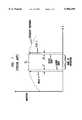
- FIG. 1shows the frequency response of a radio frequency (RF) amplifier including the location of the pilot signal.
- the pilot signalcan be near the lower edge of the operating band (e.g., pilot 1) and/or located near the upper edge of the band of operation (e.g., pilot 2).
- the pilotis positioned a spectral distance of ⁇ ⁇ from an edge of the band of operation whose center frequency is ⁇ 0 .
- the electrical characteristics (e.g., amplitude, phase response, spectral content) of the pilot signalare known. It should be noted that although the pilot signal is shown as having one or two spectral components of a certain amplitude, the pilot signal can comprise a plurality of spectral components having various amplitudes.
- the feed forward distortion reduction circuitryreduces distortion produced by the RF amplifier by applying the pilot signal to the RF amplifier and making adjustments based on information obtained from the applied pilot signal.
- FIG. 2discloses feed-forward correction circuitry 10 and its use of information obtained from the pilot signal to reduce distortion produced by RF amplifier 12.
- An input signalfor example including at least one carrier signal, is applied to a splitter 14.
- the splitter 14replicates the input signal on a main signal path 16 and a feed forward path 18.
- the splitter 14is part of a feed forward loop referred to as loop #1, which in addition to the splitter 14, comprises gain & phase circuit 20, coupler 22, the RF amplifier 12, delay circuit 24 and couplers 26 and 28.
- the signal on the main path 16is applied to gain & phase circuit 20.
- the output of gain & phase circuit 20 and the pilot signalare applied to the coupler 22.
- the amplitude of the pilot signalis much less (e.g., 30 dB less) than the amplitude of the input signal so as not to interfere with the operation of the amplifier 12.
- the output of coupler 22is applied to the amplifier 12 whose output comprises the amplified input signal, the amplified pilot signal and distortion signals produced by the amplifier 12.
- a portion of the output of the amplifier 12is obtained from the coupler 26 and is combined at the coupler 28 via coupling path 30 with a delayed version of the input signal on the feed forward path 18 to isolate the pilot signal with distortion on the feed forward path 18.
- the input signal on the feed forward path 18is sufficiently delayed by delay circuit 24 so that such signal experiences the same delay as the signal appearing at the coupler 28 via the path 30.
- the gain & phase circuit 20is controlled via control path 32 with control signals to adjust the gain and/or phase of the signal such that the signal appearing at the coupler 28 via the path 30 is substantially the inverse (equal in amplitude but 180° out of phase) of the delayed input signal at the coupler 28.
- the control signal(s) appearing on the control path 32 of the gain & phase circuit 20is derived from the signal at the output of the coupler 28 in a well known manner using a detection circuit 33.
- the detection circuit 33can include a log detector connected to a nulling circuit. As such, the amplitude of the input signal, such as a carrier signal, is detected, and the nulling circuit attempts to reduce the amplitude of the carrier signal by providing the control signals on the control path 32.
- Loop #1is thus a feed forward loop which serves to isolate on the feed forward path 18 the pilot signal with distortion produced by the amplifier 12.
- the pilot signal with distortion at the output of the coupler 28is fed to gain & phase circuit 34 whose output is fed to amplifier 36 whose output is applied to coupler 38.
- a portion of the signals on the main signal path 16 (carrier signal(s), pilot signal with distortion) after the amplifier 12is fed to a delay circuit 40 whose output is fed to the coupler 38.
- the delay circuit 40is designed such that signals from the output of the amplifier 12 applied to the coupler 38 experience substantially the same delay as the signals from the output of the amplifier 36 applied to the coupler 38.
- pilot detect circuitry 42can use detection circuits such as a log detector (or other well known detection circuits) to detect the amplitude of the pilot signal or a portion of the pilot signal via coupler 44 and a nulling circuit to reduce the amplitude of the pilot signal by providing control signals to the phase and gain circuit 34.
- detection circuitry 42will detect the pilot signal and use this information to generate control signals onto path 46 to cause the gain & phase circuit 34 to modify the pilot signal on the feed forward path 18 such that the pilot signal on the main path 16 is substantially the inverse (equal in amplitude but 180° out of phase) of the pilot signal on the feed forward path 18 at the coupler 38.
- loop #2which comprises the coupler 26, the coupler 28, the gain & phase circuit 34, the amplifier 36, the coupler 38 and the delay circuit 40 is a feed forward loop which attempts to cancel the pilot signal to cancel substantially the distortion produced by the amplifier 12.
- the present inventioninvolves a pilot signal detection system which uses a band reject filter to reject the frequency band of at least one carrier signal to improve pilot signal detection.
- the carrier signal(s)is on a main signal path along with a pilot signal which is injected into the main signal path at a frequency adjacent to the frequency band of the carrier signal(s).
- the carrier signal(s) and the pilot signalare amplified on the main signal path, resulting in distortion on the main signal path.
- the feed forward distortion reduction systemdetects and reduces the pilot signal.
- the pilot signal detection systemprovides a signal representative of the carrier signal(s) and the pilot signal with distortion from the main signal path onto a pilot detection path.
- a band reject filter on the pilot detection pathrejects the frequency band of the carrier signal(s) while allowing the frequency of the pilot signal to pass through to pilot detect circuitry. Without the presence of the carrier signal(s), the pilot detect circuitry can more accurately detect the pilot signal on the pilot detection path. In response to the detected pilot signal, the pilot detect circuitry can provide control signal(s) to improve the reduction of the pilot signal by changing the relative phase and/or gain between the signals on the main signal path and the feed forward path. Thus, by improving the detection of the pilot signal, the pilot detection system improves the reduction of the pilot signal and thereby of the distortion.
- FIG. 1shows an example frequency response curve of an RF amplifier showing the frequency within which the amplifier is operating
- FIG. 2is a block diagram of a prior art feed forward distortion reduction scheme used for RF amplifiers
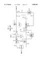
- FIG. 3shows a general block diagram of a feed forward distortion reduction system using gain and phase control according to the principles of the present invention.
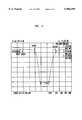
- FIG. 4shows a graphical representation of the frequency response of a band reject filter according to the principles of the present invention.
- FIG. 3shows a general block diagram of a feed forward distortion reduction system 60 which uses a pilot signal detection system 62 to improve the detection of the pilot signal.
- the pilot signal detection system 62includes a coupler 64 which provides a radio frequency (RF) representation of the amplified carrier signal(s) and the pilot signal from the main signal path 16 onto a pilot signal detection path 66.
- RFradio frequency
- a band reject filter 68rejects the frequency band of the carrier signal(s) but allows the pilot signal(s) to pass through to pilot detect circuitry 70.
- the band reject filter 68improves pilot signal detection by enabling the pilot detection circuitry 70 to detect a wider range of amplitudes for the pilot signal(s) because the carrier signals are not interfering with the pilot signal(s). It is desirable to locate the pilot as close as possible to the carrier frequency band, so that the pilot signal accurately reflects the amplifier response to the carrier frequencies. In doing so, however, the presence of the carrier signals hampers the ability to detect the lower amplitude reduced pilot signals. By using the band reject filter 68, the carrier signals are rejected from the pilot signal detection path 66, and the reduced pilot signal can be more accurately measured by the pilot detection circuitry 70.
- the pilot detect circuitry 70can include a log detector 72, which provides a direct current (DC) signal representative of the amplitude of the pilot signal, and a nulling circuit 74 which attempts to reduce the amplitude of the pilot signal by providing gain and/or phase adjustments on the control line 76 to a gain and phase circuit 78 on the feed forward path 18. Because the band reject filter 68 enables more of the amplitude of the pilot signal to be detected by pilot detect circuitry 70, the pilot detection system 62 can provide gain and/or phase control signals to more precisely cancel the pilot signal at the coupler 38, thereby improving the cancellation of the distortion on the main signal path 16.
- a log detector 72which provides a direct current (DC) signal representative of the amplitude of the pilot signal
- a nulling circuit 74which attempts to reduce the amplitude of the pilot signal by providing gain and/or phase adjustments on the control line 76 to a gain and phase circuit 78 on the feed forward path 18. Because the band reject filter 68 enables more of the amplitude of the pilot signal to be detected
- the feed forward distortion reduction system 60receives the signal S to be amplified, and the splitter 14 provides an analog representation of the signal S onto the main signal path 16 and the feed forward path 18.
- the signal S on the main signal path 16is applied to the gain & phase circuit 20.
- the output of gain & phase circuit 20is applied to the main leg of a coupler 22.
- a pilot signal generator 80generates a pilot signal and provides the pilot signal to a second leg of the coupler 22 which injects the pilot signal into the main signal path.
- the pilot signalcan have one or more spectral components or varying spectral components.
- the pilot generator 80generates a pilot signal with spectral components adjacent to and on either side of the carrier frequency band.
- the pilot signalcan be generated with spectral components at about 850 MHz and/or 920 MHz with the carrier frequency band being at between 870 and 900 MHz.
- the pilot signal(s)will be about 30 dB below the carrier signal(s).
- the pilot signal and the carrier signal on the main signal path 16are applied to the amplifier 12 whose output comprises the amplified signal S, the amplified pilot signal P and distortion D produced by the amplifier 12.
- a portion of the output S, P and D of the amplifier 12is placed on the coupling path 30 via the coupler 26 and combined with a delayed version of the signal S on the feed forward path 18 to isolate the pilot P with distortion D on the feed forward path 18.
- the gain & phase circuit 20is controlled by a phase and gain controller 33 to adjust the gain and phase of the carrier signal S on the main signal path 16 prior to the amplifier 12 such that the amplified signal S, P with D at the coupler 28 is substantially the inverse (equal in amplitude but 180° out of phase) of the delayed signal S on the path 18. As such, the combining signals cancel to isolate the pilot P and distortion D on the feed forward path 18.
- the control signal(s) appearing on the control path(s) 32 of the gain & phase circuit 20can be derived from the portion of the amplified signal S, P and D on the coupling path 30 and the delayed version of the signal S on the path 18 and/or from the output of the coupler 28.
- the gain controller 33receives a signal representing the output of the coupler 28 from a coupler 82 to determine how well the cancellation of the carrier signal S occurred at the coupler 28.
- the gain and phase controller 33can include a log detector 84, which provides a direct current (DC) signal representative of the amplitude of the signal from the coupler 82, and a nulling circuit 84 which attempts to reduce the amplitude of the signal S by providing gain and/or phase adjustments on the control line 32 to the gain and phase circuit 20 on the main signal path 16.
- DCdirect current
- the isolated pilot P and distortion D on the feed forward path 18are fed forward to cancel with the pilot P and distortion D on the main signal path 16.
- the output of the coupler 82is applied to the gain & phase adjuster 78 which adjusts the pilot signal P and distortion D on the feed forward path 18 according to phase and gain control signals from the pilot detection circuit 70.
- the output of gain and phase adjuster 78is applied to the amplifier 36 whose output comprises the amplified pilot signal and distortion D.
- the amplified pilot signal and distortion Dis output from the amplifier 36 provided to the coupler 38.
- the coupler 38destructively combines corresponding portions of the signals P and D from the feed forward path with those on the main signal path 16 to produce at the output of the coupler 38, the amplified signal S with reduced pilot signal P and distortion D.
- FIG. 4shows a graphical representation of the frequency response for the band reject filter 68 in an embodiment of the pilot detection system 62. As shown, pilot signals at 850 MHz and 920 MHz pass through the band reject filter 68 to the pilot detection circuitry 70, but the band reject filter rejects the in band carrier signals, for example between approximately 869 MHz and 894 MHz.
- band reject filter 68Other frequency bands can be rejected by the band reject filter 68, such as 1.9-2.0 gigahertz (GHz) or 2.1-2.2 GHz.
- the pilot detection circuitrycan detect a wider range of amplitudes for the reduced pilot signal(s) because the carrier signals are not hampering or interfering with the detection of the pilot signal(s).
- the band reject filter 68rejects the carrier signal(s) by about 60 dB which improves the ability to detect the pilot signal(s).
- the pilot detection circuitry 70includes the log detector 72 which receives the reduced pilot signal on the pilot detection path 66 from the band reject filter 68.
- the log detector 72produces a DC signal representative of the amplitude of the pilot signal on the path 66.
- a nulling circuit 74receives the signal representative of the amplitude of the pilot signal and attempts to reduce the amplitude of the amplitude signal from the log detector 72 by providing gain and/or phase control signals to adjust the relative phase and/or gain between the signal combining at the coupler 38.
- the pilot detect circuitry 70provides the gain and/or phase control signals to the gain and phase circuit 78 on the feed forward path 18.
- the pilot signal detection circuit 70provides gain and/or phase control signals to adjust the gain and /or phase adjustments performed on the pilot signal P and distortion D on the feed forward path 18 to improve cancellation of the pilot signal P with the distortion D from the main signal path 16 at the coupler 38.
- the pilot detection system 62can improve the reduction of the pilot signal and thereby of the distortion.
- the pilot signalis reduced to about 60 dB in amplitude below the carrier signal(s).
- pilot signal detection systemIn addition to the embodiment described above, alternative configurations of the pilot signal detection system according to the principles of the present invention are possible which omit and/or add components and/or use variations or portions of the described system. Additionally, the embodiment of the pilot detection system has been described as being used with a particular feed-forward RF amplifier arrangement, but the pilot detection system can be used to improve pilot signal detection in other amplifier or electrical circuit arrangements using a pilot signal. Additionally, the pilot detection system has been described as detecting the pilot signal(s) on both or either side of a carrier frequency band, but the pilot detection system can be used to detect a single, changing or multiple pilot signals, and the pilot signal can be positioned relative to a frequency band with multiple carriers or the frequency band of a single carrier whether outside or inside the frequency band of the multiple carriers.
- the pilot detection systemhas been described with a band reject filter which rejects the frequency band of the carrier signal(s) and permits adjacent frequencies as shown in FIG. 4. Other filters with different responses are possible which reject the carrier frequencies while allowing the pilot signal(s) to pass. Furthermore, the pilot detection system has been described as detecting pilot signal amplitude, but other parameters or characteristics of the pilot signal can be detected.
- the systemhas been described as using couplers, but other devices, such as 3 dB splitters and other coupling, signal splitting or sampling devices, can be used as well as other combining devices, such as summers.
- the gain and/or phase circuitrycan be positioned in different locations and/or paths within the feed forward amplifier arrangement.
- the pilot detection systemhas been further described as using different configurations of discrete components, but it should be understood that the feed forward system and portions thereof can be implemented in application specific integrated circuits, software-driven processing circuitry, firmware or other arrangements of discrete components as would be understood by one of ordinary skill in the art with the benefit of this disclosure. What has been described is merely illustrative of the application of the principles of the present invention. Those skilled in the art will readily recognize that these and various other modifications, arrangements and methods can be made to the present invention without strictly following the exemplary applications illustrated and described herein and without departing from the spirit and scope of the present invention.
Landscapes
- Physics & Mathematics (AREA)
- Nonlinear Science (AREA)
- Engineering & Computer Science (AREA)
- Power Engineering (AREA)
- Amplifiers (AREA)
- Noise Elimination (AREA)
Abstract
Description
Claims (15)
Priority Applications (8)
| Application Number | Priority Date | Filing Date | Title |
|---|---|---|---|
| US09/217,637US5986499A (en) | 1998-12-21 | 1998-12-21 | Pilot signal detection system using band reject filter |
| CA002289187ACA2289187C (en) | 1998-12-21 | 1999-11-09 | Pilot signal detection system using band reject filter |
| DE69901421TDE69901421T2 (en) | 1998-12-21 | 1999-12-07 | Pilot Sound Detection System with Bandstop Filter |
| EP99309847AEP1017163B1 (en) | 1998-12-21 | 1999-12-07 | Pilot signal detection system using band reject filter |
| AU64474/99AAU760868B2 (en) | 1998-12-21 | 1999-12-13 | Pilot signal detection system using band reject filter |
| JP11361259AJP2000196368A (en) | 1998-12-21 | 1999-12-20 | Distortion reducing system |
| KR1019990059171AKR20000052514A (en) | 1998-12-21 | 1999-12-20 | Pilot signal detection system using band reject filter |
| CN99126453ACN1115769C (en) | 1998-12-21 | 1999-12-21 | Pilot signal detection system using band stop filter |
Applications Claiming Priority (1)
| Application Number | Priority Date | Filing Date | Title |
|---|---|---|---|
| US09/217,637US5986499A (en) | 1998-12-21 | 1998-12-21 | Pilot signal detection system using band reject filter |
Publications (1)
| Publication Number | Publication Date |
|---|---|
| US5986499Atrue US5986499A (en) | 1999-11-16 |
Family
ID=22811884
Family Applications (1)
| Application Number | Title | Priority Date | Filing Date |
|---|---|---|---|
| US09/217,637Expired - LifetimeUS5986499A (en) | 1998-12-21 | 1998-12-21 | Pilot signal detection system using band reject filter |
Country Status (8)
| Country | Link |
|---|---|
| US (1) | US5986499A (en) |
| EP (1) | EP1017163B1 (en) |
| JP (1) | JP2000196368A (en) |
| KR (1) | KR20000052514A (en) |
| CN (1) | CN1115769C (en) |
| AU (1) | AU760868B2 (en) |
| CA (1) | CA2289187C (en) |
| DE (1) | DE69901421T2 (en) |
Cited By (24)
| Publication number | Priority date | Publication date | Assignee | Title |
|---|---|---|---|---|
| US6157254A (en)* | 1998-09-29 | 2000-12-05 | Lucent Technologies Inc. | Double side band pilot technique for a control system that reduces distortion produced by electrical circuits |
| KR20010084642A (en)* | 2000-02-28 | 2001-09-06 | 서평원 | Feeforward Linearizer with Auto Gain Control Loop |
| US20020146996A1 (en)* | 2001-03-06 | 2002-10-10 | Bachman Thomas A. | Scanning receiver for use in power amplifier linearization |
| US20020150146A1 (en)* | 1998-09-29 | 2002-10-17 | Myer Robert Evan | Frequency hop pilot technique for a control system that reduces distortion produced by electrical circuits |
| US20030001669A1 (en)* | 2001-06-29 | 2003-01-02 | Mark Billsberry | Balanced distortion reduction circuit |
| US6504430B2 (en)* | 2000-09-26 | 2003-01-07 | Kabushiki Kaisha Toshiba | Feedforward type linearizer |
| US6525603B1 (en)* | 2001-01-05 | 2003-02-25 | Remec, Inc. | Feedforward amplifier linearization adapting off modulation |
| US6700439B2 (en) | 2002-04-11 | 2004-03-02 | Andrew Corporation | Zero-bias bypass switch |
| US20040136470A1 (en)* | 2003-01-15 | 2004-07-15 | Andrew Corporation | Uncorrelated adaptive predistorter |
| US6812786B2 (en) | 2002-04-11 | 2004-11-02 | Andrew Corporation | Zero-bias bypass switching circuit using mismatched 90 degrees hybrid |
| US6829471B2 (en) | 2001-03-07 | 2004-12-07 | Andrew Corporation | Digital baseband receiver in a multi-carrier power amplifier |
| US20040251961A1 (en)* | 2003-05-07 | 2004-12-16 | Braithwaite Richard Neil | Feed forward amplifier employing positive feedback pilot generation |
| US20050017801A1 (en)* | 2003-07-23 | 2005-01-27 | Andrew Corporation | Elimination of peak clipping and improved efficiency for RF power amplifiers with a predistorter |
| US20050024138A1 (en)* | 2003-07-31 | 2005-02-03 | Andrew Corporation | Predistorter for phase modulated signals with low peak to average ratios |
| US20050073360A1 (en)* | 2003-10-06 | 2005-04-07 | Andrew Corporation | Architecture and implementation methods of digital predistortion circuitry |
| US6972622B2 (en) | 2003-05-12 | 2005-12-06 | Andrew Corporation | Optimization of error loops in distributed power amplifiers |
| US7729668B2 (en) | 2003-04-03 | 2010-06-01 | Andrew Llc | Independence between paths that predistort for memory and memory-less distortion in power amplifiers |
| US7729419B1 (en)* | 2006-11-24 | 2010-06-01 | Kiomars Anvari | Reconditioning equalizer filter using convolution |
| US7796687B1 (en)* | 2006-11-24 | 2010-09-14 | Kiomars Anvari | Enhanced reconditioning equalizer filter chain for multi-carrier signals with different technologies |
| US7817713B1 (en)* | 2006-11-24 | 2010-10-19 | Kiomars Anvari | Enhanced reconditioning equalizer filter for non-constant envelop signals |
| US7848403B1 (en)* | 2004-02-20 | 2010-12-07 | Kiomars Anvari | Enhanced reconditioning equalizer filter chain for multi-carrier signals |
| CN101226074B (en)* | 2007-01-19 | 2012-09-05 | Itt制造企业公司 | Rotating device, pump system and method for determining liquid level of the rotating equipment |
| US8619847B1 (en)* | 2006-11-24 | 2013-12-31 | Altera Corporation | Reconditioning equalizer filter for non-constant envelop signals |
| WO2019080783A1 (en)* | 2017-10-23 | 2019-05-02 | Huawei Technologies Co., Ltd. | Monitoring performance of optical network equipment using pilot tones |
Citations (10)
| Publication number | Priority date | Publication date | Assignee | Title |
|---|---|---|---|---|
| US4580105A (en)* | 1985-01-25 | 1986-04-01 | At&T Bell Laboratories | Automatic reduction of intermodulation products in high power linear amplifiers |
| US4583049A (en)* | 1984-06-15 | 1986-04-15 | Trw Inc. | Feed-forward circuit |
| US4885551A (en)* | 1988-10-31 | 1989-12-05 | American Telephone And Telegraph Company At&T Bell Laboratories | Feed forward linear amplifier |
| US4926136A (en)* | 1988-12-29 | 1990-05-15 | Westinghouse Electric Corp. | Power amplifier combiner for improving linearity of an output |
| US5012490A (en)* | 1989-12-26 | 1991-04-30 | At&T Bell Laboratories | Varying bandwidth digital signal detector |
| US5304945A (en)* | 1993-04-19 | 1994-04-19 | At&T Bell Laboratories | Low-distortion feed-forward amplifier |
| US5430893A (en)* | 1993-08-11 | 1995-07-04 | At&T Corp. | Radio receiver with increased dynamic range |
| US5619168A (en)* | 1995-08-07 | 1997-04-08 | Lucent Technologies Inc. | Distortion creation and reduction circuit |
| US5796304A (en)* | 1996-04-24 | 1998-08-18 | Powerwave Technologies, Inc. | Broadband amplifier with quadrature pilot signal |
| US5847603A (en)* | 1997-07-31 | 1998-12-08 | Lucent Technologies Inc. | Automatic control system for reducing distortion produced by electrical circuits |
Family Cites Families (1)
| Publication number | Priority date | Publication date | Assignee | Title |
|---|---|---|---|---|
| US5770971A (en)* | 1996-07-26 | 1998-06-23 | Northern Telecom Limited | Distortion compensation control for a power amplifier |
- 1998
- 1998-12-21USUS09/217,637patent/US5986499A/ennot_activeExpired - Lifetime
- 1999
- 1999-11-09CACA002289187Apatent/CA2289187C/ennot_activeExpired - Fee Related
- 1999-12-07DEDE69901421Tpatent/DE69901421T2/ennot_activeExpired - Lifetime
- 1999-12-07EPEP99309847Apatent/EP1017163B1/ennot_activeExpired - Lifetime
- 1999-12-13AUAU64474/99Apatent/AU760868B2/ennot_activeCeased
- 1999-12-20KRKR1019990059171Apatent/KR20000052514A/ennot_activeCeased
- 1999-12-20JPJP11361259Apatent/JP2000196368A/enactivePending
- 1999-12-21CNCN99126453Apatent/CN1115769C/ennot_activeExpired - Fee Related
Patent Citations (10)
| Publication number | Priority date | Publication date | Assignee | Title |
|---|---|---|---|---|
| US4583049A (en)* | 1984-06-15 | 1986-04-15 | Trw Inc. | Feed-forward circuit |
| US4580105A (en)* | 1985-01-25 | 1986-04-01 | At&T Bell Laboratories | Automatic reduction of intermodulation products in high power linear amplifiers |
| US4885551A (en)* | 1988-10-31 | 1989-12-05 | American Telephone And Telegraph Company At&T Bell Laboratories | Feed forward linear amplifier |
| US4926136A (en)* | 1988-12-29 | 1990-05-15 | Westinghouse Electric Corp. | Power amplifier combiner for improving linearity of an output |
| US5012490A (en)* | 1989-12-26 | 1991-04-30 | At&T Bell Laboratories | Varying bandwidth digital signal detector |
| US5304945A (en)* | 1993-04-19 | 1994-04-19 | At&T Bell Laboratories | Low-distortion feed-forward amplifier |
| US5430893A (en)* | 1993-08-11 | 1995-07-04 | At&T Corp. | Radio receiver with increased dynamic range |
| US5619168A (en)* | 1995-08-07 | 1997-04-08 | Lucent Technologies Inc. | Distortion creation and reduction circuit |
| US5796304A (en)* | 1996-04-24 | 1998-08-18 | Powerwave Technologies, Inc. | Broadband amplifier with quadrature pilot signal |
| US5847603A (en)* | 1997-07-31 | 1998-12-08 | Lucent Technologies Inc. | Automatic control system for reducing distortion produced by electrical circuits |
Cited By (35)
| Publication number | Priority date | Publication date | Assignee | Title |
|---|---|---|---|---|
| US6157254A (en)* | 1998-09-29 | 2000-12-05 | Lucent Technologies Inc. | Double side band pilot technique for a control system that reduces distortion produced by electrical circuits |
| US20020150146A1 (en)* | 1998-09-29 | 2002-10-17 | Myer Robert Evan | Frequency hop pilot technique for a control system that reduces distortion produced by electrical circuits |
| KR20010084642A (en)* | 2000-02-28 | 2001-09-06 | 서평원 | Feeforward Linearizer with Auto Gain Control Loop |
| US6504430B2 (en)* | 2000-09-26 | 2003-01-07 | Kabushiki Kaisha Toshiba | Feedforward type linearizer |
| US6525603B1 (en)* | 2001-01-05 | 2003-02-25 | Remec, Inc. | Feedforward amplifier linearization adapting off modulation |
| US20050032485A1 (en)* | 2001-03-06 | 2005-02-10 | Andrew Corporation | Scanning receiver for use in power amplifier linearization |
| US20020146996A1 (en)* | 2001-03-06 | 2002-10-10 | Bachman Thomas A. | Scanning receiver for use in power amplifier linearization |
| US7167693B2 (en) | 2001-03-06 | 2007-01-23 | Andrew Corporation | Scanning receiver for use in power amplifier linearization |
| US6829471B2 (en) | 2001-03-07 | 2004-12-07 | Andrew Corporation | Digital baseband receiver in a multi-carrier power amplifier |
| US20030001669A1 (en)* | 2001-06-29 | 2003-01-02 | Mark Billsberry | Balanced distortion reduction circuit |
| US6734726B2 (en) | 2001-06-29 | 2004-05-11 | Remec, Inc. | Balanced distortion reduction circuit |
| US6700439B2 (en) | 2002-04-11 | 2004-03-02 | Andrew Corporation | Zero-bias bypass switch |
| US6812786B2 (en) | 2002-04-11 | 2004-11-02 | Andrew Corporation | Zero-bias bypass switching circuit using mismatched 90 degrees hybrid |
| US20040136470A1 (en)* | 2003-01-15 | 2004-07-15 | Andrew Corporation | Uncorrelated adaptive predistorter |
| US7403573B2 (en) | 2003-01-15 | 2008-07-22 | Andrew Corporation | Uncorrelated adaptive predistorter |
| US7729668B2 (en) | 2003-04-03 | 2010-06-01 | Andrew Llc | Independence between paths that predistort for memory and memory-less distortion in power amplifiers |
| US20040251961A1 (en)* | 2003-05-07 | 2004-12-16 | Braithwaite Richard Neil | Feed forward amplifier employing positive feedback pilot generation |
| US7123086B2 (en)* | 2003-05-07 | 2006-10-17 | Powerwave Technologies, Inc. | Feed forward amplifier employing positive feedback pilot generation |
| US6972622B2 (en) | 2003-05-12 | 2005-12-06 | Andrew Corporation | Optimization of error loops in distributed power amplifiers |
| US7259630B2 (en) | 2003-07-23 | 2007-08-21 | Andrew Corporation | Elimination of peak clipping and improved efficiency for RF power amplifiers with a predistorter |
| US20050017801A1 (en)* | 2003-07-23 | 2005-01-27 | Andrew Corporation | Elimination of peak clipping and improved efficiency for RF power amplifiers with a predistorter |
| US20050024138A1 (en)* | 2003-07-31 | 2005-02-03 | Andrew Corporation | Predistorter for phase modulated signals with low peak to average ratios |
| US6963242B2 (en) | 2003-07-31 | 2005-11-08 | Andrew Corporation | Predistorter for phase modulated signals with low peak to average ratios |
| US7023273B2 (en) | 2003-10-06 | 2006-04-04 | Andrew Corporation | Architecture and implementation methods of digital predistortion circuitry |
| US20050073360A1 (en)* | 2003-10-06 | 2005-04-07 | Andrew Corporation | Architecture and implementation methods of digital predistortion circuitry |
| US7848403B1 (en)* | 2004-02-20 | 2010-12-07 | Kiomars Anvari | Enhanced reconditioning equalizer filter chain for multi-carrier signals |
| US7796687B1 (en)* | 2006-11-24 | 2010-09-14 | Kiomars Anvari | Enhanced reconditioning equalizer filter chain for multi-carrier signals with different technologies |
| US7817713B1 (en)* | 2006-11-24 | 2010-10-19 | Kiomars Anvari | Enhanced reconditioning equalizer filter for non-constant envelop signals |
| US7729419B1 (en)* | 2006-11-24 | 2010-06-01 | Kiomars Anvari | Reconditioning equalizer filter using convolution |
| US8619847B1 (en)* | 2006-11-24 | 2013-12-31 | Altera Corporation | Reconditioning equalizer filter for non-constant envelop signals |
| US8787438B1 (en)* | 2006-11-24 | 2014-07-22 | Altera Corporation | Reconditioning equalizer filter for non-constant envelope signals |
| US8989253B1 (en)* | 2006-11-24 | 2015-03-24 | Altera Corporation | Reconditioning equalizer filter for non-constant envelope signals |
| CN101226074B (en)* | 2007-01-19 | 2012-09-05 | Itt制造企业公司 | Rotating device, pump system and method for determining liquid level of the rotating equipment |
| WO2019080783A1 (en)* | 2017-10-23 | 2019-05-02 | Huawei Technologies Co., Ltd. | Monitoring performance of optical network equipment using pilot tones |
| US10574351B2 (en) | 2017-10-23 | 2020-02-25 | Huawei Technologies Co., Ltd. | Monitoring performance of optical network equipment using pilot tones |
Also Published As
| Publication number | Publication date |
|---|---|
| AU6447499A (en) | 2000-06-22 |
| EP1017163A1 (en) | 2000-07-05 |
| DE69901421D1 (en) | 2002-06-13 |
| CN1260633A (en) | 2000-07-19 |
| EP1017163B1 (en) | 2002-05-08 |
| CA2289187A1 (en) | 2000-06-21 |
| CN1115769C (en) | 2003-07-23 |
| KR20000052514A (en) | 2000-08-25 |
| DE69901421T2 (en) | 2003-01-16 |
| JP2000196368A (en) | 2000-07-14 |
| CA2289187C (en) | 2004-05-25 |
| AU760868B2 (en) | 2003-05-22 |
Similar Documents
| Publication | Publication Date | Title |
|---|---|---|
| US5986499A (en) | Pilot signal detection system using band reject filter | |
| US5077532A (en) | Feed forward distortion minimization circuit | |
| US6127889A (en) | Nested feed forward distortion reduction system | |
| US6052023A (en) | Calibration system for feed forward distortion reduction system | |
| EP1191684B1 (en) | System and method for producing an amplified signal using a pilot signal with different frequencies across a spectrum | |
| US6157254A (en) | Double side band pilot technique for a control system that reduces distortion produced by electrical circuits | |
| JP4896424B2 (en) | Distortion compensation amplifier | |
| JP4709446B2 (en) | Feedforward nonlinear distortion compensation amplifier | |
| US6553211B1 (en) | Method and apparatus for adjusting pilot signal relative to input signal | |
| CA2254229C (en) | Improved pilot detection for a control system that reduces distortion produced by electrical circuits | |
| CA2315583C (en) | Alternating gain and phase control system and method | |
| US6654591B1 (en) | Low distortion signal amplifier system and method | |
| KR20000023532A (en) | Frequency hop pilot technique for a control system that reduces distortion produced by electrical circuits |
Legal Events
| Date | Code | Title | Description |
|---|---|---|---|
| AS | Assignment | Owner name:LUCENT TECHNOLOGIES INC., NEW JERSEY Free format text:ASSIGNMENT OF ASSIGNORS INTEREST;ASSIGNOR:MYER, ROBERT E.;REEL/FRAME:009668/0969 Effective date:19981111 | |
| STCF | Information on status: patent grant | Free format text:PATENTED CASE | |
| FEPP | Fee payment procedure | Free format text:PAYOR NUMBER ASSIGNED (ORIGINAL EVENT CODE: ASPN); ENTITY STATUS OF PATENT OWNER: LARGE ENTITY | |
| AS | Assignment | Owner name:THE CHASE MANHATTAN BANK, AS COLLATERAL AGENT, TEX Free format text:CONDITIONAL ASSIGNMENT OF AND SECURITY INTEREST IN PATENT RIGHTS;ASSIGNOR:LUCENT TECHNOLOGIES INC. (DE CORPORATION);REEL/FRAME:011722/0048 Effective date:20010222 | |
| FPAY | Fee payment | Year of fee payment:4 | |
| AS | Assignment | Owner name:LUCENT TECHNOLOGIES INC., NEW JERSEY Free format text:TERMINATION AND RELEASE OF SECURITY INTEREST IN PATENT RIGHTS;ASSIGNOR:JPMORGAN CHASE BANK, N.A. (FORMERLY KNOWN AS THE CHASE MANHATTAN BANK), AS ADMINISTRATIVE AGENT;REEL/FRAME:018590/0047 Effective date:20061130 | |
| FPAY | Fee payment | Year of fee payment:8 | |
| FPAY | Fee payment | Year of fee payment:12 | |
| AS | Assignment | Owner name:CREDIT SUISSE AG, NEW YORK Free format text:SECURITY INTEREST;ASSIGNOR:ALCATEL-LUCENT USA INC.;REEL/FRAME:030510/0627 Effective date:20130130 | |
| AS | Assignment | Owner name:ALCATEL-LUCENT USA INC., NEW JERSEY Free format text:RELEASE BY SECURED PARTY;ASSIGNOR:CREDIT SUISSE AG;REEL/FRAME:033950/0261 Effective date:20140819 | |
| AS | Assignment | Owner name:OMEGA CREDIT OPPORTUNITIES MASTER FUND, LP, NEW YORK Free format text:SECURITY INTEREST;ASSIGNOR:WSOU INVESTMENTS, LLC;REEL/FRAME:043966/0574 Effective date:20170822 Owner name:OMEGA CREDIT OPPORTUNITIES MASTER FUND, LP, NEW YO Free format text:SECURITY INTEREST;ASSIGNOR:WSOU INVESTMENTS, LLC;REEL/FRAME:043966/0574 Effective date:20170822 | |
| AS | Assignment | Owner name:WSOU INVESTMENTS, LLC, CALIFORNIA Free format text:ASSIGNMENT OF ASSIGNORS INTEREST;ASSIGNOR:ALCATEL LUCENT;REEL/FRAME:044000/0053 Effective date:20170722 | |
| AS | Assignment | Owner name:WSOU INVESTMENTS, LLC, CALIFORNIA Free format text:RELEASE BY SECURED PARTY;ASSIGNOR:OCO OPPORTUNITIES MASTER FUND, L.P. (F/K/A OMEGA CREDIT OPPORTUNITIES MASTER FUND LP;REEL/FRAME:049246/0405 Effective date:20190516 | |
| AS | Assignment | Owner name:OT WSOU TERRIER HOLDINGS, LLC, CALIFORNIA Free format text:SECURITY INTEREST;ASSIGNOR:WSOU INVESTMENTS, LLC;REEL/FRAME:056990/0081 Effective date:20210528 |