US5985060A - Gas generant compositions containing guanidines - Google Patents
Gas generant compositions containing guanidinesDownload PDFInfo
- Publication number
- US5985060A US5985060AUS09/122,545US12254598AUS5985060AUS 5985060 AUS5985060 AUS 5985060AUS 12254598 AUS12254598 AUS 12254598AUS 5985060 AUS5985060 AUS 5985060A
- Authority
- US
- United States
- Prior art keywords
- weight
- gas generant
- nitrate
- concentration
- gas
- Prior art date
- Legal status (The legal status is an assumption and is not a legal conclusion. Google has not performed a legal analysis and makes no representation as to the accuracy of the status listed.)
- Expired - Lifetime
Links
- 239000000203mixtureSubstances0.000titleclaimsabstractdescription74
- 150000002357guanidinesChemical class0.000titledescription3
- DHEQXMRUPNDRPG-UHFFFAOYSA-Nstrontium nitrateChemical compound[Sr+2].[O-][N+]([O-])=O.[O-][N+]([O-])=ODHEQXMRUPNDRPG-UHFFFAOYSA-N0.000claimsabstractdescription32
- 239000000446fuelSubstances0.000claimsabstractdescription28
- 239000008188pelletSubstances0.000claimsabstractdescription28
- GDDNTTHUKVNJRA-UHFFFAOYSA-N3-bromo-3,3-difluoroprop-1-eneChemical compoundFC(F)(Br)C=CGDDNTTHUKVNJRA-UHFFFAOYSA-N0.000claimsabstractdescription26
- IDCPFAYURAQKDZ-UHFFFAOYSA-N1-nitroguanidineChemical compoundNC(=N)N[N+]([O-])=OIDCPFAYURAQKDZ-UHFFFAOYSA-N0.000claimsabstractdescription22
- NDEMNVPZDAFUKN-UHFFFAOYSA-Nguanidine;nitric acidChemical compoundNC(N)=N.O[N+]([O-])=O.O[N+]([O-])=ONDEMNVPZDAFUKN-UHFFFAOYSA-N0.000claimsabstractdescription22
- 239000007800oxidant agentSubstances0.000claimsabstractdescription21
- VWDWKYIASSYTQR-UHFFFAOYSA-Nsodium nitrateChemical compound[Na+].[O-][N+]([O-])=OVWDWKYIASSYTQR-UHFFFAOYSA-N0.000claimsabstractdescription16
- UAGLZAPCOXRKPH-UHFFFAOYSA-Nnitric acid;1,2,3-triaminoguanidineChemical compoundO[N+]([O-])=O.NNC(NN)=NNUAGLZAPCOXRKPH-UHFFFAOYSA-N0.000claimsabstractdescription15
- BVGPZRCQJJMXBI-UHFFFAOYSA-N1,2-diaminoguanidine;nitric acidChemical compoundO[N+]([O-])=O.NN\C(N)=N/NBVGPZRCQJJMXBI-UHFFFAOYSA-N0.000claimsabstractdescription10
- 239000004317sodium nitrateSubstances0.000claimsabstractdescription8
- 235000010344sodium nitrateNutrition0.000claimsabstractdescription8
- CNUNWZZSUJPAHX-UHFFFAOYSA-Nguanidine nitrateChemical compoundNC(N)=N.O[N+]([O-])=OCNUNWZZSUJPAHX-UHFFFAOYSA-N0.000claimsabstractdescription5
- UQSXHKLRYXJYBZ-UHFFFAOYSA-NIron oxideChemical compound[Fe]=OUQSXHKLRYXJYBZ-UHFFFAOYSA-N0.000claimsdescription16
- 239000003054catalystSubstances0.000claimsdescription16
- JGDFBJMWFLXCLJ-UHFFFAOYSA-Ncopper chromiteChemical group[Cu]=O.[Cu]=O.O=[Cr]O[Cr]=OJGDFBJMWFLXCLJ-UHFFFAOYSA-N0.000claimsdescription15
- 238000002156mixingMethods0.000claimsdescription5
- 229910001963alkali metal nitrateInorganic materials0.000claimsdescription4
- 229910001964alkaline earth metal nitrateInorganic materials0.000claimsdescription4
- DMBHHRLKUKUOEG-UHFFFAOYSA-NdiphenylamineChemical compoundC=1C=CC=CC=1NC1=CC=CC=C1DMBHHRLKUKUOEG-UHFFFAOYSA-N0.000claimsdescription4
- 239000000020NitrocelluloseSubstances0.000claimsdescription3
- 229920001220nitrocellulosPolymers0.000claimsdescription3
- 238000005453pelletizationMethods0.000claimsdescription2
- 238000004519manufacturing processMethods0.000abstractdescription13
- 238000000034methodMethods0.000abstractdescription11
- 150000001540azidesChemical class0.000abstractdescription10
- 238000005382thermal cyclingMethods0.000abstractdescription5
- 239000007789gasSubstances0.000description106
- 238000012360testing methodMethods0.000description28
- 238000002485combustion reactionMethods0.000description19
- 238000005033Fourier transform infrared spectroscopyMethods0.000description16
- 229910052751metalInorganic materials0.000description15
- 239000002184metalSubstances0.000description15
- XLYOFNOQVPJJNP-UHFFFAOYSA-NwaterSubstancesOXLYOFNOQVPJJNP-UHFFFAOYSA-N0.000description15
- 239000000463materialSubstances0.000description14
- ZRALSGWEFCBTJO-UHFFFAOYSA-NGuanidineChemical compoundNC(N)=NZRALSGWEFCBTJO-UHFFFAOYSA-N0.000description9
- MWUXSHHQAYIFBG-UHFFFAOYSA-NNitric oxideChemical compoundO=[N]MWUXSHHQAYIFBG-UHFFFAOYSA-N0.000description8
- PAWQVTBBRAZDMG-UHFFFAOYSA-N2-(3-bromo-2-fluorophenyl)acetic acidChemical compoundOC(=O)CC1=CC=CC(Br)=C1FPAWQVTBBRAZDMG-UHFFFAOYSA-N0.000description7
- UGFAIRIUMAVXCW-UHFFFAOYSA-NCarbon monoxideChemical compound[O+]#[C-]UGFAIRIUMAVXCW-UHFFFAOYSA-N0.000description7
- ULRPISSMEBPJLN-UHFFFAOYSA-N2h-tetrazol-5-amineChemical compoundNC1=NN=NN1ULRPISSMEBPJLN-UHFFFAOYSA-N0.000description6
- 229910002091carbon monoxideInorganic materials0.000description6
- 239000003623enhancerSubstances0.000description6
- 239000007787solidSubstances0.000description6
- 238000004458analytical methodMethods0.000description5
- 230000008859changeEffects0.000description5
- 239000000567combustion gasSubstances0.000description5
- 238000001035dryingMethods0.000description5
- 229960004198guanidineDrugs0.000description5
- -1triazole compoundChemical class0.000description5
- VEXZGXHMUGYJMC-UHFFFAOYSA-NHydrochloric acidChemical compoundClVEXZGXHMUGYJMC-UHFFFAOYSA-N0.000description4
- CHJJGSNFBQVOTG-UHFFFAOYSA-NN-methyl-guanidineNatural productsCNC(N)=NCHJJGSNFBQVOTG-UHFFFAOYSA-N0.000description4
- 230000015556catabolic processEffects0.000description4
- 239000007795chemical reaction productSubstances0.000description4
- 230000006378damageEffects0.000description4
- 238000006731degradation reactionMethods0.000description4
- SWSQBOPZIKWTGO-UHFFFAOYSA-NdimethylaminoamidineNatural productsCN(C)C(N)=NSWSQBOPZIKWTGO-UHFFFAOYSA-N0.000description4
- 238000001914filtrationMethods0.000description4
- 238000010304firingMethods0.000description4
- IXCSERBJSXMMFS-UHFFFAOYSA-Nhydrogen chlorideSubstancesCl.ClIXCSERBJSXMMFS-UHFFFAOYSA-N0.000description4
- 229910000041hydrogen chlorideInorganic materials0.000description4
- 230000008569processEffects0.000description4
- UHOVQNZJYSORNB-UHFFFAOYSA-NBenzeneChemical compoundC1=CC=CC=C1UHOVQNZJYSORNB-UHFFFAOYSA-N0.000description3
- 150000001875compoundsChemical class0.000description3
- 238000002474experimental methodMethods0.000description3
- 239000011888foilSubstances0.000description3
- 239000004009herbicideSubstances0.000description3
- 239000000047productSubstances0.000description3
- 150000003536tetrazolesChemical class0.000description3
- KJUGUADJHNHALS-UHFFFAOYSA-N1H-tetrazoleSubstancesC=1N=NNN=1KJUGUADJHNHALS-UHFFFAOYSA-N0.000description2
- MGWGWNFMUOTEHG-UHFFFAOYSA-N4-(3,5-dimethylphenyl)-1,3-thiazol-2-amineChemical compoundCC1=CC(C)=CC(C=2N=C(N)SC=2)=C1MGWGWNFMUOTEHG-UHFFFAOYSA-N0.000description2
- QGZKDVFQNNGYKY-UHFFFAOYSA-NAmmoniaChemical compoundNQGZKDVFQNNGYKY-UHFFFAOYSA-N0.000description2
- OKTJSMMVPCPJKN-UHFFFAOYSA-NCarbonChemical compound[C]OKTJSMMVPCPJKN-UHFFFAOYSA-N0.000description2
- CURLTUGMZLYLDI-UHFFFAOYSA-NCarbon dioxideChemical compoundO=C=OCURLTUGMZLYLDI-UHFFFAOYSA-N0.000description2
- 229910002089NOxInorganic materials0.000description2
- 239000006057Non-nutritive feed additiveSubstances0.000description2
- VYPSYNLAJGMNEJ-UHFFFAOYSA-NSilicium dioxideChemical compoundO=[Si]=OVYPSYNLAJGMNEJ-UHFFFAOYSA-N0.000description2
- 229910000831SteelInorganic materials0.000description2
- RAHZWNYVWXNFOC-UHFFFAOYSA-NSulphur dioxideChemical compoundO=S=ORAHZWNYVWXNFOC-UHFFFAOYSA-N0.000description2
- FJWGYAHXMCUOOM-QHOUIDNNSA-N[(2s,3r,4s,5r,6r)-2-[(2r,3r,4s,5r,6s)-4,5-dinitrooxy-2-(nitrooxymethyl)-6-[(2r,3r,4s,5r,6s)-4,5,6-trinitrooxy-2-(nitrooxymethyl)oxan-3-yl]oxyoxan-3-yl]oxy-3,5-dinitrooxy-6-(nitrooxymethyl)oxan-4-yl] nitrateChemical compoundO([C@@H]1O[C@@H]([C@H]([C@H](O[N+]([O-])=O)[C@H]1O[N+]([O-])=O)O[C@H]1[C@@H]([C@@H](O[N+]([O-])=O)[C@H](O[N+]([O-])=O)[C@@H](CO[N+]([O-])=O)O1)O[N+]([O-])=O)CO[N+](=O)[O-])[C@@H]1[C@@H](CO[N+]([O-])=O)O[C@@H](O[N+]([O-])=O)[C@H](O[N+]([O-])=O)[C@H]1O[N+]([O-])=OFJWGYAHXMCUOOM-QHOUIDNNSA-N0.000description2
- 239000000853adhesiveSubstances0.000description2
- 230000001070adhesive effectEffects0.000description2
- 150000001298alcoholsChemical class0.000description2
- 150000001340alkali metalsChemical class0.000description2
- QVGXLLKOCUKJST-UHFFFAOYSA-Natomic oxygenChemical compound[O]QVGXLLKOCUKJST-UHFFFAOYSA-N0.000description2
- 229910052788bariumInorganic materials0.000description2
- DSAJWYNOEDNPEQ-UHFFFAOYSA-Nbarium atomChemical compound[Ba]DSAJWYNOEDNPEQ-UHFFFAOYSA-N0.000description2
- 230000015572biosynthetic processEffects0.000description2
- 239000006227byproductSubstances0.000description2
- HSJPMRKMPBAUAU-UHFFFAOYSA-Ncerium(3+);trinitrateChemical compound[Ce+3].[O-][N+]([O-])=O.[O-][N+]([O-])=O.[O-][N+]([O-])=OHSJPMRKMPBAUAU-UHFFFAOYSA-N0.000description2
- 239000000460chlorineSubstances0.000description2
- 238000005336crackingMethods0.000description2
- 239000013078crystalSubstances0.000description2
- 238000013461designMethods0.000description2
- 238000001514detection methodMethods0.000description2
- 238000011161developmentMethods0.000description2
- 230000018109developmental processEffects0.000description2
- 238000004817gas chromatographyMethods0.000description2
- 239000001257hydrogenSubstances0.000description2
- 229910052739hydrogenInorganic materials0.000description2
- 150000002431hydrogenChemical class0.000description2
- LELOWRISYMNNSU-UHFFFAOYSA-Nhydrogen cyanideChemical compoundN#CLELOWRISYMNNSU-UHFFFAOYSA-N0.000description2
- 230000007774longtermEffects0.000description2
- 238000002844meltingMethods0.000description2
- 230000008018meltingEffects0.000description2
- VNWKTOKETHGBQD-UHFFFAOYSA-NmethaneChemical compoundCVNWKTOKETHGBQD-UHFFFAOYSA-N0.000description2
- 238000012986modificationMethods0.000description2
- 230000004048modificationEffects0.000description2
- JCXJVPUVTGWSNB-UHFFFAOYSA-Nnitrogen dioxideInorganic materialsO=[N]=OJCXJVPUVTGWSNB-UHFFFAOYSA-N0.000description2
- 231100000252nontoxicToxicity0.000description2
- 230000003000nontoxic effectEffects0.000description2
- NDLPOXTZKUMGOV-UHFFFAOYSA-Noxo(oxoferriooxy)iron hydrateChemical compoundO.O=[Fe]O[Fe]=ONDLPOXTZKUMGOV-UHFFFAOYSA-N0.000description2
- 239000001301oxygenSubstances0.000description2
- 229910052760oxygenInorganic materials0.000description2
- 239000002245particleSubstances0.000description2
- 239000000575pesticideSubstances0.000description2
- IMACFCSSMIZSPP-UHFFFAOYSA-Nphenacyl chlorideChemical compoundClCC(=O)C1=CC=CC=C1IMACFCSSMIZSPP-UHFFFAOYSA-N0.000description2
- FGIUAXJPYTZDNR-UHFFFAOYSA-Npotassium nitrateChemical compound[K+].[O-][N+]([O-])=OFGIUAXJPYTZDNR-UHFFFAOYSA-N0.000description2
- 239000000843powderSubstances0.000description2
- 239000003380propellantSubstances0.000description2
- 230000009467reductionEffects0.000description2
- 239000002893slagSubstances0.000description2
- 239000000779smokeSubstances0.000description2
- 239000010959steelSubstances0.000description2
- 239000000126substanceSubstances0.000description2
- 239000003491tear gasSubstances0.000description2
- 231100000041toxicology testingToxicity0.000description2
- 229910000314transition metal oxideInorganic materials0.000description2
- MVXMNHYVCLMLDD-UHFFFAOYSA-N4-methoxynaphthalene-1-carbaldehydeChemical compoundC1=CC=C2C(OC)=CC=C(C=O)C2=C1MVXMNHYVCLMLDD-UHFFFAOYSA-N0.000description1
- 239000005997Calcium carbideSubstances0.000description1
- VEXZGXHMUGYJMC-UHFFFAOYSA-MChloride anionChemical compound[Cl-]VEXZGXHMUGYJMC-UHFFFAOYSA-M0.000description1
- ZAMOUSCENKQFHK-UHFFFAOYSA-NChlorine atomChemical compound[Cl]ZAMOUSCENKQFHK-UHFFFAOYSA-N0.000description1
- VYZAMTAEIAYCRO-UHFFFAOYSA-NChromiumChemical compound[Cr]VYZAMTAEIAYCRO-UHFFFAOYSA-N0.000description1
- PODSFSFGMHOAFM-UHFFFAOYSA-MCl(=O)(=O)(=O)[O-].FN(F)[N+](CCOC)(N(F)F)N(F)FChemical compoundCl(=O)(=O)(=O)[O-].FN(F)[N+](CCOC)(N(F)F)N(F)FPODSFSFGMHOAFM-UHFFFAOYSA-M0.000description1
- RYGMFSIKBFXOCR-UHFFFAOYSA-NCopperChemical compound[Cu]RYGMFSIKBFXOCR-UHFFFAOYSA-N0.000description1
- LFQSCWFLJHTTHZ-UHFFFAOYSA-NEthanolChemical compoundCCOLFQSCWFLJHTTHZ-UHFFFAOYSA-N0.000description1
- 229910017344Fe2 O3Inorganic materials0.000description1
- PXGOKWXKJXAPGV-UHFFFAOYSA-NFluorineChemical compoundFFPXGOKWXKJXAPGV-UHFFFAOYSA-N0.000description1
- 229910003556H2 SO4Inorganic materials0.000description1
- DGAQECJNVWCQMB-PUAWFVPOSA-MIlexoside XXIXChemical compoundC[C@@H]1CC[C@@]2(CC[C@@]3(C(=CC[C@H]4[C@]3(CC[C@@H]5[C@@]4(CC[C@@H](C5(C)C)OS(=O)(=O)[O-])C)C)[C@@H]2[C@]1(C)O)C)C(=O)O[C@H]6[C@@H]([C@H]([C@@H]([C@H](O6)CO)O)O)O.[Na+]DGAQECJNVWCQMB-PUAWFVPOSA-M0.000description1
- 229910002651NO3Inorganic materials0.000description1
- NHNBFGGVMKEFGY-UHFFFAOYSA-NNitrateChemical compound[O-][N+]([O-])=ONHNBFGGVMKEFGY-UHFFFAOYSA-N0.000description1
- 101100386054Saccharomyces cerevisiae (strain ATCC 204508 / S288c) CYS3 geneProteins0.000description1
- NINIDFKCEFEMDL-UHFFFAOYSA-NSulfurChemical compound[S]NINIDFKCEFEMDL-UHFFFAOYSA-N0.000description1
- 208000027418Wounds and injuryDiseases0.000description1
- XWROSHJVVFETLV-UHFFFAOYSA-N[B+3].[O-][N+]([O-])=O.[O-][N+]([O-])=O.[O-][N+]([O-])=OChemical compound[B+3].[O-][N+]([O-])=O.[O-][N+]([O-])=O.[O-][N+]([O-])=OXWROSHJVVFETLV-UHFFFAOYSA-N0.000description1
- DQOJFOIRUMWLAV-UHFFFAOYSA-N[Cl-].[NH4+].C1=CC=CC=C1Chemical compound[Cl-].[NH4+].C1=CC=CC=C1DQOJFOIRUMWLAV-UHFFFAOYSA-N0.000description1
- PFRUBEOIWWEFOL-UHFFFAOYSA-N[N].[S]Chemical compound[N].[S]PFRUBEOIWWEFOL-UHFFFAOYSA-N0.000description1
- LRFQSNDOLFTQCR-UHFFFAOYSA-M[O-][Cr](O)(=O)=O.N.[Cu+]Chemical compound[O-][Cr](O)(=O)=O.N.[Cu+]LRFQSNDOLFTQCR-UHFFFAOYSA-M0.000description1
- 238000010521absorption reactionMethods0.000description1
- 230000009471actionEffects0.000description1
- 239000000654additiveSubstances0.000description1
- 230000000996additive effectEffects0.000description1
- 239000000443aerosolSubstances0.000description1
- 230000032683agingEffects0.000description1
- 229910052783alkali metalInorganic materials0.000description1
- PNEYBMLMFCGWSK-UHFFFAOYSA-Naluminium oxideInorganic materials[O-2].[O-2].[O-2].[Al+3].[Al+3]PNEYBMLMFCGWSK-UHFFFAOYSA-N0.000description1
- 229910021529ammoniaInorganic materials0.000description1
- KHPLPBHMTCTCHA-UHFFFAOYSA-Nammonium chlorateChemical classN.OCl(=O)=OKHPLPBHMTCTCHA-UHFFFAOYSA-N0.000description1
- 230000009286beneficial effectEffects0.000description1
- 239000011230binding agentSubstances0.000description1
- CJZGTCYPCWQAJB-UHFFFAOYSA-Lcalcium stearateChemical compound[Ca+2].CCCCCCCCCCCCCCCCCC([O-])=O.CCCCCCCCCCCCCCCCCC([O-])=OCJZGTCYPCWQAJB-UHFFFAOYSA-L0.000description1
- 239000008116calcium stearateSubstances0.000description1
- 235000013539calcium stearateNutrition0.000description1
- 229910052799carbonInorganic materials0.000description1
- CREMABGTGYGIQB-UHFFFAOYSA-Ncarbon carbonChemical compoundC.CCREMABGTGYGIQB-UHFFFAOYSA-N0.000description1
- 239000001569carbon dioxideSubstances0.000description1
- 229910002092carbon dioxideInorganic materials0.000description1
- 239000011203carbon fibre reinforced carbonSubstances0.000description1
- 125000003178carboxy groupChemical group[H]OC(*)=O0.000description1
- 229920002678cellulosePolymers0.000description1
- 239000001913celluloseSubstances0.000description1
- 238000006243chemical reactionMethods0.000description1
- 239000003795chemical substances by applicationSubstances0.000description1
- 229910052801chlorineInorganic materials0.000description1
- ZCDOYSPFYFSLEW-UHFFFAOYSA-Nchromate(2-)Chemical class[O-][Cr]([O-])(=O)=OZCDOYSPFYFSLEW-UHFFFAOYSA-N0.000description1
- 229910052804chromiumInorganic materials0.000description1
- 239000011651chromiumSubstances0.000description1
- 230000008094contradictory effectEffects0.000description1
- 239000002826coolantSubstances0.000description1
- 238000001816coolingMethods0.000description1
- 229910052802copperInorganic materials0.000description1
- 150000001879copperChemical class0.000description1
- 239000010949copperSubstances0.000description1
- 238000000354decomposition reactionMethods0.000description1
- 239000008367deionised waterSubstances0.000description1
- 229910021641deionized waterInorganic materials0.000description1
- 230000001419dependent effectEffects0.000description1
- 229910003460diamondInorganic materials0.000description1
- 239000010432diamondSubstances0.000description1
- QGBSISYHAICWAH-UHFFFAOYSA-NdicyandiamideChemical compoundNC(N)=NC#NQGBSISYHAICWAH-UHFFFAOYSA-N0.000description1
- 238000009826distributionMethods0.000description1
- 239000000428dustSubstances0.000description1
- 239000000975dyeSubstances0.000description1
- 150000002148estersChemical class0.000description1
- 239000002360explosiveSubstances0.000description1
- KTWOOEGAPBSYNW-UHFFFAOYSA-NferroceneChemical class[Fe+2].C=1C=C[CH-]C=1.C=1C=C[CH-]C=1KTWOOEGAPBSYNW-UHFFFAOYSA-N0.000description1
- 239000000835fiberSubstances0.000description1
- 239000011737fluorineSubstances0.000description1
- 229910052731fluorineInorganic materials0.000description1
- 229920002313fluoropolymerPolymers0.000description1
- 239000004811fluoropolymerSubstances0.000description1
- WTDFFADXONGQOM-UHFFFAOYSA-Nformaldehyde;hydrochlorideChemical compoundCl.O=CWTDFFADXONGQOM-UHFFFAOYSA-N0.000description1
- 238000009472formulationMethods0.000description1
- 238000013467fragmentationMethods0.000description1
- 238000006062fragmentation reactionMethods0.000description1
- 239000002316fumigantSubstances0.000description1
- 239000010439graphiteSubstances0.000description1
- 229910002804graphiteInorganic materials0.000description1
- 238000000227grindingMethods0.000description1
- 230000036541healthEffects0.000description1
- 238000010438heat treatmentMethods0.000description1
- 230000003116impacting effectEffects0.000description1
- 208000014674injuryDiseases0.000description1
- 238000007689inspectionMethods0.000description1
- 150000002576ketonesChemical class0.000description1
- 239000007788liquidSubstances0.000description1
- 231100000053low toxicityToxicity0.000description1
- MYGMBVDLWDZOIL-UHFFFAOYSA-Nmethane;cyanideChemical compoundC.N#[C-]MYGMBVDLWDZOIL-UHFFFAOYSA-N0.000description1
- WSFSSNUMVMOOMR-NJFSPNSNSA-NmethanoneChemical compoundO=[14CH2]WSFSSNUMVMOOMR-NJFSPNSNSA-N0.000description1
- CWQXQMHSOZUFJS-UHFFFAOYSA-Nmolybdenum disulfideChemical compoundS=[Mo]=SCWQXQMHSOZUFJS-UHFFFAOYSA-N0.000description1
- 229910052982molybdenum disulfideInorganic materials0.000description1
- 150000004682monohydratesChemical group0.000description1
- TVBSSDNEJWXWFP-UHFFFAOYSA-Nnitric acid perchloric acidChemical compoundO[N+]([O-])=O.OCl(=O)(=O)=OTVBSSDNEJWXWFP-UHFFFAOYSA-N0.000description1
- 150000002829nitrogenChemical class0.000description1
- 230000009972noncorrosive effectEffects0.000description1
- VLTRZXGMWDSKGL-UHFFFAOYSA-Nperchloric acidChemical classOCl(=O)(=O)=OVLTRZXGMWDSKGL-UHFFFAOYSA-N0.000description1
- 231100000572poisoningToxicity0.000description1
- 230000000607poisoning effectEffects0.000description1
- 239000004323potassium nitrateSubstances0.000description1
- 235000010333potassium nitrateNutrition0.000description1
- 238000002360preparation methodMethods0.000description1
- 238000003825pressingMethods0.000description1
- 238000012545processingMethods0.000description1
- 230000001681protective effectEffects0.000description1
- 230000002385psychotomimetic effectEffects0.000description1
- 238000004064recyclingMethods0.000description1
- 239000011347resinSubstances0.000description1
- 229920005989resinPolymers0.000description1
- 150000003839saltsChemical class0.000description1
- 230000035945sensitivityEffects0.000description1
- 230000035939shockEffects0.000description1
- 239000000377silicon dioxideSubstances0.000description1
- 235000012239silicon dioxideNutrition0.000description1
- 239000002002slurrySubstances0.000description1
- 229910052708sodiumInorganic materials0.000description1
- 239000011734sodiumSubstances0.000description1
- UPDATVKGFTVGQJ-UHFFFAOYSA-Nsodium;azaneChemical compoundN.[Na+]UPDATVKGFTVGQJ-UHFFFAOYSA-N0.000description1
- 239000004449solid propellantSubstances0.000description1
- 229910001220stainless steelInorganic materials0.000description1
- 239000010935stainless steelSubstances0.000description1
- 238000003860storageMethods0.000description1
- 101150035983str1 geneProteins0.000description1
- 229910052717sulfurInorganic materials0.000description1
- 239000011593sulfurSubstances0.000description1
- QAOWNCQODCNURD-UHFFFAOYSA-Nsulfuric acidSubstancesOS(O)(=O)=OQAOWNCQODCNURD-UHFFFAOYSA-N0.000description1
- 230000002459sustained effectEffects0.000description1
- CLZWAWBPWVRRGI-UHFFFAOYSA-Ntert-butyl 2-[2-[2-[2-[bis[2-[(2-methylpropan-2-yl)oxy]-2-oxoethyl]amino]-5-bromophenoxy]ethoxy]-4-methyl-n-[2-[(2-methylpropan-2-yl)oxy]-2-oxoethyl]anilino]acetateChemical compoundCC1=CC=C(N(CC(=O)OC(C)(C)C)CC(=O)OC(C)(C)C)C(OCCOC=2C(=CC=C(Br)C=2)N(CC(=O)OC(C)(C)C)CC(=O)OC(C)(C)C)=C1CLZWAWBPWVRRGI-UHFFFAOYSA-N0.000description1
- 239000002341toxic gasSubstances0.000description1
- 230000007704transitionEffects0.000description1
- 150000003852triazolesChemical class0.000description1
- 238000013022ventingMethods0.000description1
- 235000012431wafersNutrition0.000description1
- 238000003466weldingMethods0.000description1
Images

Classifications
- C—CHEMISTRY; METALLURGY
- C06—EXPLOSIVES; MATCHES
- C06D—MEANS FOR GENERATING SMOKE OR MIST; GAS-ATTACK COMPOSITIONS; GENERATION OF GAS FOR BLASTING OR PROPULSION (CHEMICAL PART)
- C06D5/00—Generation of pressure gas, e.g. for blasting cartridges, starting cartridges, rockets
- C06D5/06—Generation of pressure gas, e.g. for blasting cartridges, starting cartridges, rockets by reaction of two or more solids
Definitions
- the present inventionrelates to non-azide gas generants containing guanidines that are useful for inflating an airbag in a vehicle occupant protection system.
- Automobile airbag systemshave been developed to protect vehicle occupants in the event of a crash by rapidly inflating a cushion or bag between a vehicle occupant and the interior of the vehicle.
- the inflated airbagabsorbs the vehicle occupant's energy to provide a gradual, controlled deceleration and provides a cushion to distribute body loads and keep the occupant from impacting the hard surfaces of the vehicle interior.
- the gas generantmust efficiently produce a relatively cool, non-toxic, non-corrosive gas which is easily filtered to remove solid and liquid combustion by-products. This filtering is needed to preclude damage to the inflatable airbag or injury to the occupant of the automobile. These requirements limit the applicability of many otherwise suitable chemical compositions, shapes and configurations from being used in automotive airbag inflators. Gas generants can also be used for fire extinguishing. Recently, a number of companies have begun using the gases produced by solid energetic or pyrotechnique materials for fire extinguishing.
- gas generant pelletAn important parameter relating to gas generants is physical stability of the gas generant pellet. As mentioned above, physical forces, such as vibration, can abrade or crack the gas generant pellets. This damage is unacceptable as the surface area is increased and thus the ballistics (rate of combustion) are altered. Ballistics can also be altered through the absorption of water and thermal cycling. It is known that most non-azide based gas generants, especially 5-aminotetrazole, are hygroscopic and soften upon heating. These changes cause the gas generant pellet to degrade or crumble. This change in surface area can result in catastrophic failure of the inflator housing due to excessive pressure build up in the housing at the time of ignition.
- a source of water for degradation of a generant pelletis the gas generant itself.
- Many non-azide gas generantsare prepared by an aqueous mixing process. Water is used to mix the non-azide fuel, oxidizer, and other components of the gas generant composition. The majority of the water is removed during a drying step, however, at least 1% by weight and sometimes as high as 5% by weight water still remains in the generant composition. This drying step is expensive and dangerous. Any method that would allow the gas generant to be prepared without the use of water would be readily accepted by the industry.
- the present inventionovercomes the previously described problems through the use of guanidines as the fuel and an oxidizer system comprising strontium nitrate and ammonium perchlorate.
- the inventionas it relates to the inflator housing, comprises the use of a metal ribbon with a plurality of apertures and a segment of expanded metal that is rolled into a coil and used as a filter to trap combustion products.
- U.S. Pat. No. 5,500,059 to Lund et al.teaches a gas generant composition comprising an oxidizer and anhydrous 5-aminotetrazole as the fuel.
- This patentpoints out that 5-aminotetrazole (5-AT) is generally in the monohydrate form and that gas generating compositions based upon hydrated tetrazoles have unacceptably low burning rates.
- this patentteaches a method for the production of gas generant pellets comprising the steps of: a)preparing a water slurry of an oxidizer and hydrated 5-aminotetrazole; b) drying the slurried material to a constant weight; c) pressing said material into pellets in hydrated form; and d) drying said pellets such that the gas generating material is in anhydrous or substantially anhydrous form.
- This patentteaches that if the material is pressed into pellets while in the anhydrous form, the pellets are observed to powder and crumble, particularly when exposed to a humid environment. This reference goes on to state that after the final drying step, it is desirable to protect the pellets from exposure to moisture. It is further suggested that the pellets be placed within a sealed container, or coated with a water impermeable material.
- U.S. Pat. No. 5,467,715 to Taylor et al.relates to a gas generant composition that contains, as a fuel, a mixture of triazoles or tetrazoles with a minor portion of a water soluble fuel and an oxidizer component wherein 20 weight % of the oxidizer component is a transition metal oxide.
- U.S. Pat. No. 5,529,647 to Taylor et al.teaches a gas generant for airbags which comprises between 2 and 45 weight % of a tetrazole or triazole compound; from 50-75 weight % of an oxidizer such as ammonium nitrate, ammonium perchlorate, transition metal oxides and mixtures thereof; from 0.5 to about 30 weight % of alumina fibers; and between about 1 and 10 weight % of a binder such as molybdenum disulfide, graphite, nitrocellulose, calcium stearate and mixtures thereof.
- an oxidizersuch as ammonium nitrate, ammonium perchlorate, transition metal oxides and mixtures thereof
- alumina fibersfrom 0.5 to about 30 weight % of alumina fibers
- a bindersuch as molybdenum disulfide, graphite, nitrocellulose, calcium stearate and mixtures thereof.
- U.S. Pat. No. 5,531,941 to Pooleteaches an azide-free gas generant composition that comprises a mixture of triaminoguanidine nitrate (TAGN) as the fuel and phase stabilized ammonium nitrate (PSAN) as the oxidizer.
- TAGNtriaminoguanidine nitrate
- PSANphase stabilized ammonium nitrate
- ANammonium nitrate
- U.S. Pat. No. 3,031,347 to Philipsonteaches to solid propellant materials useful in rocket or jet propulsion motors.
- the slow burning propellant composition of Philipsonuses an oxidizer selected from ammonium perchlorate, ammonium nitrate and mixtures thereof at concentrations of from 45 to 72 weight %.
- the Philipson compositionalso uses 5-22 weight % of an oxygen rich additive selected from the group consisting of guanidine nitrate, nitroguanidine, cellulose nitrate and mixtures thereof; and 23-36 weight % of a polymerized resin fuel.
- an automobile airbag gas generantcan be prepared from a mixture of at least two fuels selected from guanidine nitrate (GN), nitroguanidine (NG), triaminoguanidine nitrate (TAGN), diaminoguanidine nitrate (DAGN) and monoguanidine nitrate (MGN); an oxidizer system which is a mixture of alkali metal nitrates, alkaline earth metal nitrates and ammonium perchlorate; and a catalyst selected from copper chromite, iron oxide and mixtures thereof.
- GNguanidine nitrate
- NGnitroguanidine
- TAGNtriaminoguanidine nitrate
- DAGNdiaminoguanidine nitrate
- MGNmonoguanidine nitrate
- an oxidizer systemwhich is a mixture of alkali metal nitrates, alkaline earth metal nitrates and ammonium perchlorate
- a catalyst
- U.S. Pat. No. 3,929,530 to Nilesteaches a pyrotechnic composition for colored smoke production and for the distribution of pesticides, fumigants, herbicides and the like.
- the pyrotechnic disseminating composition taught in this referenceemploys an amino-substituted thiourea compound as a fuel; inorganic oxidizers such as alkali metal and ammonium chlorates and perchlorates; combustion catalysts such as chromates, copper salts, metal chromites, ferric oxide and the like; and a compound to be disseminated such as smoke producing organic dyes, tear gas, herbicides, pesticides, psychotomimetic incapacitating agents and the like.
- the gas generant compositioncomprises: (a) a fuel component which is used at a level between about 45 and about 70 weight %, which comprises a mixture of at least two fuels selected from the group consisting of guanidine nitrate (GN), nitroguanidine (NG), triaminoguanidine nitrate (TAGN), diaminoguanidine nitrate (DAGN) and monoguanidine nitrate (MGN); and (b) an oxidizer component which is used at a level of between about 25 and about 50 weight %, which comprises a mixture of the alkali metal nitrates, alkaline earth metal nitrates, and ammonium perchlorate.
- a fuel componentwhich is used at a level between about 45 and about 70 weight %, which comprises a mixture of at least two fuels selected from the group consisting of guanidine nitrate (GN), nitroguanidine (NG), triaminoguanidine nitrate (TAGN), diamino
- the catalystmay preferably be selected from copper chromite, iron oxide, and mixtures thereof and may comprise from 0.1 to 1.0 weight % of the composition.
- the fuel componentcomprises a mixture of NG and GN;
- the oxidizer componentcomprises a mixture of strontium nitrate (SN), ammonium perchlorate (AP) and sodium nitrate (NaN); and the catalyst is copper chromite (CuCr).
- the gas generant compositioncomprises 10-20 weight % NG, 35-50 weight % GN, 5-15 weight % strontium nitrate (SN), 15-25 weight % ammonium perchlorate (AP), 5-25 weight % sodium nitrate (NaN) and 0.1-0.3 weight % copper chromite.
- the compositioncomprises 14-17 weight % of NG, 40-43 weight % of GN, 7-10 weight % SN, 21-24 weight % AP, 10-13 weight % NaN and about 0.2-0.3 weight % copper chromite (CuCr).
- inventive gas generantinclude: the quantity of harmful gases that are generated upon combustion is below specified limits; a high gas output (at least 700 mols/kg of generant); low toxicity of basic materials and reaction products; sufficient chemical and thermal stability; low sensitivity to friction and impact; low cost of production; availability of basic materials; processing on a large scale is possible; and potential for recycling.
- One aspect of the inventionrelates to a method of producing the gas generant composition without the use of water.
- the processcomprises the dry blending of all the components and then pelletizing.
- a dry blenderi.e., a tubular mixer
- the fuels and the oxidizerssuch as AP, NaN and SN
- This dry blendthen has added to it the CuCr.
- the productis then pelletized using conventional equipment and techniques to produce pellets of from 5-500 mgs. It is preferred that the fuels, oxidizers and catalyst be substantially anhydrous.
- the gas generants of the inventionwhile primarily directed to use in vehicle occupant restraint systems, can also be applied to fire extinguishing systems. Further, the generants of the invention are particularly useful in the all-chemical-generated gas system. The generants are also very useful in hybrid systems which feature a gas generant unit in combination with a stored gas unit.
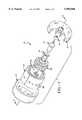
- FIG. 1is an exploded view of an inflator used in the tests described herein and employing the inventive filter system
- FIG. 2Ais a top plan view of one embodiment of the metallic ribbon used to prepare the filter coil according to the invention.
- FIG. 2Bis a top plan view of a second embodiment of the metallic ribbon.
- FIG. 3is a side view in cross section of the inflator taken along line 3--3 of FIG. 1.
- the gas generant formulations used in this inventionare formulated from the guanidine family of fuels such as guanidine nitrate (GN), triaminoguanidine nitrate (TAGN) and the like.
- the fuel componentwill typically comprise between about 45 and about 70 weight %, more preferably between 50 and 60 weight %, of the gas generant composition, while the oxidizer system will typically comprise between about 35 and about 50 weight %, more preferably between 40 and 50 weight %, of the gas generant composition.
- Processing aidssuch as silicon dioxide, may also be used in formulating the gas generant pellets. Those skilled in the art understand that depending upon the particular oxidizers and fuels utilized, certain processing aids have beneficial properties over others.
- the fuel useful in the gas generant of the present inventionis a mixture of at least two guanidine fuels selected from guanidine nitrate (GN), nitroguanidine (NG), triaminoguanidine nitrate (TAGN), diaminoguanidine nitrate (DAGN) and monoguanidine nitrate (MGN).
- GNguanidine nitrate
- NGnitroguanidine
- TAGNtriaminoguanidine nitrate
- DAGNdiaminoguanidine nitrate
- MGNmonoguanidine nitrate
- Guanidine or iminoureaCH 5 N 3
- Guanidineis soluble in water and alcohol, volatile and strongly alkaline. It forms many salts, e.g., nitrate and the like.
- Nitroguanidineis a white crystalline powder which is usually manufactured from calcium carbide via calcium cyanamide, dicyandiamide and guanidine nitrate which is converted to nitroguanidine by action of concentrated sulfuric acid. Nitroguanidine has the structural formula: ##STR2##
- Oxidizers useful in the gas generant compositionsinclude ammonium perchlorate and the alkali metal and alkaline earth metal nitrates such as strontium nitrate and sodium nitrate.
- the preferred oxidizer systemis a mixture of strontium nitrate, sodium nitrate and ammonium perchlorate.
- Ammonium perchlorateis important to the gas generant of the invention due to its gaseous decomposition and lack of particulate production.
- the potential problem of HCl generationmay be overcome through the use of copper chromite and/or iron oxide as a catalyst and/or the sodium from the sodium nitrate.
- One aspect of the inventionis the discovery that AP, which is a component that the industry has a propensity to avoid due to HCl generation, is useful in the inventive gas generants.
- the gas generants of the inventionproduce barely detectable levels of chloride containing gases.
- the ratio of oxidizer to fuel in the inventive gas generantis adjusted such that the amount of oxygen allowed in the equilibrium exhaust gases is from zero to 2 or 3% by volume, and more preferably from zero to 2.0% by volume.
- the gas generant compositionmay optionally contain up to about 1.0 weight %, typically between about 0.1 and about 0.3 weight %, of iron oxide, copper chromite or mixtures thereof as catalysts.
- Copper chromite (CuCr)has known properties as a catalyst. It is a mixed oxide of copper and chromium obtained by igniting copper ammonium chromate under controlled conditions. Barium is frequently added to prevent poisoning of the catalyst, however, the CuCr used in the present invention is preferably free of barium. Copper chromite is principally used for the reduction of carboxyl groups (e.g., ketones to alcohols, and esters to alcohols). The preferred level of copper chromite in the inventive composition is about 0.25 weight %.
- the iron oxide (Fe 2 O 3 ) useful in the inventive compositionsmay be obtained by all the usual methods.
- the particle size of the iron oxide and CuCrmay vary from about 1 to 10 microns.
- an inflator 10employed in testing several of the gas generant compositions disclosed herein.
- a first housing member 12 and a second housing member 22are attached to one another through "friction or inertia welding".
- the inflator 10also comprises an inventive strip filter 14, an enhancer tube 16, a squib with enhancer cup 18 and a room temperature vulcanizing rubber seal 20.
- a bed of gas generant pellets 30is disposed between the strip filter 14 and the enhancer tube 16.
- Metal foilnot shown, lines the annular surface of the first housing 12 covering gas exit portals 34 in the first housing.
- FIGS. 2A and 2Bthere is represented two (2) embodiments of the inventive filter strip 14.
- Both embodiments of the filter stripcontain at least three (3) segments wherein the first segment 28 (a.k.a. the inside portion) has two (2) rows of apertures therethrough positioned along each edge of the ribbon, an expanded metal segment 29 and second segment 15 wherein at least one row of apertures are present.
- FIG. 2Ais an embodiment wherein the second segment 15 has two (2) rows of a plurality of apertures 26 therethrough with diameter of about 2.0 mm.
- FIG. 2Brepresents a second embodiment where the second segment 15 has a single row of apertures 26 therethrough with a diameter of about 4 mm. The placement of the apertures is important for complete combustion of the generant.
- the first segmentwhich is adjacent the generant bed, requires apertures along each edges, while the second or final segment must have the aperture in the center of the ribbon.
- the size and number of the aperturescan be varied to control the desired combustion level (i.e., rate of pressure generation).
- the filter stripis coiled or rolled into a tubular configuration which is placed inside the inflator 10.
- the inventorshave discovered that a metallic filter strip or ribbon with a combination of segments with holes and a segment of expanded metal can economically produce a filter that effectively cools the gas and removes particulates and slag generated when the gas generant is burned.
- the metal from which the filter strip 14 is producedcan be any metal with a melting point high enough to survive the combustion of the gas generant.
- the thickness of the stripcan range from about 0.25 mm to 1.27 mm with about 0.51 mm to 0.76 mm being more preferred, about 0.63 mm being the most preferred.
- the length and height of the stripcan vary widely depending upon the size and configuration of the inflator housing into which it is placed.
- the filter stripis designed such that first segment 28 will complete the first turn during the formation of the coil and the expanded metal segment 29 will complete at least two turns of the coil.
- the expanded metal segment 29will complete at least three turns.
- the second segment 15is of such length that it will completely circumferentially cover the outside of the coil.
- apertures 24 in the first segment 28are not aligned with, and do not overlay, the apertures 26 in the second segment 15.
- the apertures 24are disposed towards the outside edge of segment 28 while the apertures 26 in the second segment 15 are disposed towards the interior.
- This aspectis important as it aids in creating a tortuous path for the gases.
- the use of the expanded metal segmentprovides a large surface area for the capture of particulates and cooling of the gas and also creates a tortuous path for the gases.
- the expanded metal segment 29should be long enough to accomplish at least two (2) turns during the formation of the coil.
- the diamond shaped openings in the expanded metal segment 29should have a dimension of about 0.04 to 0.12 mm by 0.32 to 0.8 mm.
- the expanded metal stripcan be made by die cut stamping and the apertures can be drilled or stamped out.
- FIG. 3is a cross section of an inflator housing taken along line 3--3 of FIG. 1 except that the squib with enhancer cup 18 is not shown in cross section.
- the bed of gas generant 36is not shown for clarity.
- the inflator housing 10comprises a first housing member 12 and a second housing member 22 that, in this representative embodiment, are attached by a spin weld 32. Other forms of attachment such as threaded engagement, laser welds and mechanical fixation, are within the scope of the invention.
- the filtration strip 14 in coiled configurationis shown as having five (5) turns in FIG. 1.
- the apertures 24 through the first segment 28can be in other arrangements than shown, i.e., in a random pattern, provided the apertures 24 are not directly across from the apertures 26 through the second segment. This is required so that the combustion gas must take a tortuous path through the expanded metal to the apertures 26 and then through the exit portals 34.
- One additional aspect of the inventionis that through subtle changes in the levels of the various components, the combustion temperature and igniting behavior of the generant can be modified to function in a variety of inflator configurations.
- changing the combustion level and temperaturewill change the CO and NO x content of the combustion gas as well as output.
- reduction of the combustion temperature by using a coolantgives disadvantages relating to CO and NO x content as well as output levels.
- at high output temperatureit leads to potential disadvantages with respect to damage to the airbag.
- Gas generant developmentshould be understood to be a task of balancing contradicting properties in order to fulfill very special requirements.
- reaction behavior of a gas generantin areas other than basic chemistry, depends on igniting behavior, combustion surface area and design of the inflator housing which influences pressure build-up.
- design of the inflator housingcan influence the properties of the gas generated through pressure build up as a result of filtering capabilities.
- a one Kg batch of a gas generant compositionwas formulated according to Table I below.
- the compositionswere prepared by grinding the individual components (when needed, i.e., NaN) to a particle size of less than 100 microns and then all of the components of the generant were sifted and then blended in a Turbula® mixer (manufactured by W.A.B. of Switzerland). Mixing continued for one (1) hour.
- the materialwas then pelletized with a rotary pellet press.
- the pelletswere about 5 mm in diameter, 1.8 mm high, weighed about 55 to 65 mg each and had a density of about 1.6 to 1.7 g/cm 3 .
- the formed pelletswere then loaded into steel inflators of the type shown in FIG. 1. Either about 19 or 23 gms of the pellets were loaded into each of the steel housings.
- the 19 gm charge of generantwas for a 40 liter airbag while the 23 gm charge was for a 60 liter airbag.
- the burst foil or tapecomprises a thin sheet (about 0.005 mm. thick) of stainless steel with an adhesive on one side. The adhesive side of the burst foil is placed against the inside surface of the inflator housing so as to hermetically seal all of the apertures 34.
- the apertures 34are exhaust ports for the gases generated by the generant and were about 2.4 mm in diameter for the 40 liter airbag and about 2.5 mm for the 60 liter airbag.
- the number of apertures 34was four.
- the test inflator housinghad a total volume of about 88 cm 3 , while the region of the housing located inwardly of the filter and containing the pellets of gas generating material had a volume of about 46 cm 3 for the 40 liter airbag and about 46 cm 3 for the 60 liter airbag.
- the inflatoralso incorporated about 0.9 g of BKNO 3 (a mixture of boron nitrate and potassium nitrate, conventionally used in the industry), as an enhancer and was associated with the squib with enhancer cup 18.
- Example No. 5Two (2) assembled inflators containing 19 gms of the inventive gas generant pellets (Sample No. 5) were evaluated in a (100 cubic foot) test chamber fitted with equipment to record the pressure and time profile of the combustion and to analyze the gases exiting the inflator. The amount of particulate or slag produced by the burning generant was also determined using standardized techniques.
- the inflatorswere installed into the test chamber and the gas generant pellets were ignited. The temperature of the inflator at firing was about 23° C. ⁇ 2° C. at a relative humidity of about 43%.
- gas sampleswere withdrawn from the test chamber for analysis by FTIR (Fourier Transform Infrared Spectroscopy).
- Airborne particulate productionwas measured by filtering post ignition air from the test chamber through a fine filter and measuring the weight gained by the filter.
- the average total airborne particulate mass for the two (2) testswas 6.85 mg.
- the average total particulate concentration for the two (2) testswas 68.5 mg/m 3 .
- test chamberwas attached to a vacuum pump, a bubble flow meter, filters and a FT/IR gas analyzer (spectrophotometer). Gas samples were analyzed using an FTIR spectrometer at zero time (before deployment) and at 1, 5, 10, 15 and 20 minute intervals after ignition or via gas chromatography.
- Total particulate production from each testwas also collected. Following venting of the tank to the atmosphere, the interior of the 60 liter test chamber was carefully scrubbed and rinsed with deionized water to measure particulate production.
- the particulate produced by gas generantscomprises a mixture of water soluble and insoluble reaction products.
- the aqueous mixture of the soluble reaction products and the insoluble dustwere analyzed to determine total particulate production.
- Table IVsets forth the insoluble, soluble and total particulates for each run.
- gas generant composition according to the inventionproduces a relatively clean gas upon combustion; that is, from a 19 gm charge of generant, less than 1.5 gms of solids exit the inflator.
- the gas generant according to the inventionis useful for inflating airbags and can also be used as fire extinguishers.
- the generants of the inventionare virtually unaffected by temperature extremes and possess excellent ignition and combustion properties.
- APammonium perchlorate
- the automobile industryis in search of gas generants that are free of the problems associated with the use of azide gas generants.
- the industryis also in need of non-azide based generants that have good, long term stability against moisture degradation and thermal cycling degradation.
- the gas generant compositions of this invention and the process for their manufacturemeet these needs. Further, through the use of a novel combination of materials and a unique process of production, the gas generant of the invention produces a very acceptable gas for the inflation of airbags. Further, the gas generants according to this invention would also find use in fire extinguishing systems using solid energetic materials for producing fire extinguishing gases.
Landscapes
- Chemical & Material Sciences (AREA)
- Chemical Kinetics & Catalysis (AREA)
- Engineering & Computer Science (AREA)
- Combustion & Propulsion (AREA)
- Organic Chemistry (AREA)
- Air Bags (AREA)
- Feeding, Discharge, Calcimining, Fusing, And Gas-Generation Devices (AREA)
Abstract
Description
TABLE I __________________________________________________________________________Values in Weight % Sample Nitro- Guanidine Strontium Ammonium Sodium Nitro- No. guanidine nitrate nitrate perchlorate nitrate cellulose DPA* CuCr __________________________________________________________________________1 15 40 10 22 11 2 0.1 -- 2 15 40 10 22 11 2 -- -- 3 15 42 10 22 11 -- -- -- 4 15 41.5 10 22 11 -- -- 0.5 5 15.5 41.5 8.8 22.8 11.4 -- -- 0.25 6 13.5 44 9 22 11 -- -- 0.5 7 15 40 10 22 11 2 0.1 0.25 __________________________________________________________________________ *DPA diphenylamine
TABLE II __________________________________________________________________________Gaseous Effluent Data __________________________________________________________________________ Carbon Carbon Hydrogen Ammonia Benzene Chloride Dioxide Monoxide Formaldehyde Chloride __________________________________________________________________________Analysis Method FTIR FTIR Tube FTIR FTIR FTIR FTIR Detection Limit 5 5 0.2 50 10 2 2 (ppm) Analysis Delay 0.2 0.2 30 0.2 0.2 0.2 0.2 (min) Sample No. 5 1 <5 <5 * 995 142 <2 <2 (Test I) 5 <5 <5 * 840 117 <2 <2 10 <5 <5 * 792 109 <2 <2 15 <5 <5 * 765 106 <2 <2 20 <5 <5 * 745 103 <2 <2 TWA <5 <5 ** 811 113 <2 <2 20 Sample No. 5 1 <5 <5 * 805 107 <2 <2 (Test II) 5 <5 <5 * 863 108 <2 <2 10 <5 <5 <0.2 796 100 <2 <2 15 <5 <5 * 765 96 <2 <2 20 <5 <5 * 754 94 <2 <2 TWA <5 <5 ** 799 101 <2 <2 20 __________________________________________________________________________ Hydrogen Nitric Nitrogen Sulfur Water cyanide Methane Oxide dioxide Phosgene dioxide Vapor __________________________________________________________________________Analysis Method FTIR FTIR FTIR FTIR Tube FTIR FTIR Detection Limit 2 5 2 0.5 0.02 5 500 (ppm) Analysis Delay 0.2 0.2 0.2 0.2 30 0.2 0.2 (min) Sample No. 5 1 12 19 28 <0.5 * <5 1379 (Test I) 5 10 16 22 1.1 * <5 515 10 9 14 20 1.7 * <5 <500 15 8 14 18 2 * <5 <500 20 8 13 17 2.4 * <5 <500 TWA 9 15 20 1.6 ** <5 <500 20 Sample No. 5 1 8 14 25 <0.5 * <5 3159 (Test II) 5 8 14 24 1.4 * <5 3337 10 8 12 22 2 <0.02 <5 3104 15 8 12 20 2.7 * <5 2897 20 7 12 18 3.1 * <5 2780 TWA 8 13 22 2 ** <5 3068 20 __________________________________________________________________________ * Compound was not analyzed at this time interval ** TWA (total weight average) could not be calculated + Gas chromatography tube
TABLE III ______________________________________ Tank Pressure for Ambient, 90° C. and -40° C. Tests Max. Time to Max Area under Pressure Pressure the Curve Test (psi) (ms) (PSI *ms) ______________________________________ Ambient I 30.1 49.8 4672.7 Ambient II 29.7 51.6 4615.2 Ambient III 29.5 50.2 4561.3 90° C. I 33.9 40.6 5221.7 90° C. II 32.9 42.2 5093.1 90° C. III 32.3 42.0 4979.0 -40° C. I 26.8 57.4 4119.4 -40° C. II 26.8 58.8 4101.0 -40° C. III 26.2 54.8 4012.3 ______________________________________
TABLE IV ______________________________________ Particulate Production Insoluble Soluble Particulates Particulates Total Test (mg) (mg) (mgs) ______________________________________ Ambient I 217 760 977 Ambient II 128 658 786 Ambient III 162 727 889 90° C. I 335 1008 1343 90° C. II 363 1041 1404 90° C. III 180 1036 1216 -40° C. I 273 819 1092 -40° C. II 319 760 1079 -40° C. III 271 777 1048 ______________________________________
TABLE V __________________________________________________________________________Gas Toxicity Testing - PPM Test CO NO NO.sub.2 NH.sub.3 CO.sub.2 HCl Cl.sub.2 H.sub.2 S COCL.sub.2 __________________________________________________________________________Ambient I 3746 467 214 <5 (2.6%) <5 <0.2 <0.2 <0.02 Ambient II 3513 320 325 <5 (2.6%) <5 <0.2 <0.2 <0.02 Ambient III 3773 253 391 <5 (2.7%) <5 <0.2 <0.2 <0.02 __________________________________________________________________________ () = value may be inaccurate, exceeds highest calibration standard.
Claims (10)
Priority Applications (3)
| Application Number | Priority Date | Filing Date | Title |
|---|---|---|---|
| US09/122,545US5985060A (en) | 1998-07-25 | 1998-07-25 | Gas generant compositions containing guanidines |
| PCT/US1999/013128WO2000006523A1 (en) | 1998-07-25 | 1999-06-10 | Gas generant compositions containing guanadines |
| EP99928554AEP1114010A4 (en) | 1998-07-25 | 1999-06-10 | Gas generant compositions containing guanadines |
Applications Claiming Priority (1)
| Application Number | Priority Date | Filing Date | Title |
|---|---|---|---|
| US09/122,545US5985060A (en) | 1998-07-25 | 1998-07-25 | Gas generant compositions containing guanidines |
Publications (1)
| Publication Number | Publication Date |
|---|---|
| US5985060Atrue US5985060A (en) | 1999-11-16 |
Family
ID=22403328
Family Applications (1)
| Application Number | Title | Priority Date | Filing Date |
|---|---|---|---|
| US09/122,545Expired - LifetimeUS5985060A (en) | 1998-07-25 | 1998-07-25 | Gas generant compositions containing guanidines |
Country Status (3)
| Country | Link |
|---|---|
| US (1) | US5985060A (en) |
| EP (1) | EP1114010A4 (en) |
| WO (1) | WO2000006523A1 (en) |
Cited By (16)
| Publication number | Priority date | Publication date | Assignee | Title |
|---|---|---|---|---|
| US6132480A (en)* | 1999-04-22 | 2000-10-17 | Autoliv Asp, Inc. | Gas forming igniter composition for a gas generant |
| US6156230A (en)* | 1998-08-07 | 2000-12-05 | Atrantic Research Corporation | Metal oxide containing gas generating composition |
| US20040074651A1 (en)* | 2002-10-10 | 2004-04-22 | International Business Machines Corporation | Conformal coating enhanced to provide heat detection |
| US20050115722A1 (en)* | 2003-12-02 | 2005-06-02 | Lund Gary K. | Method and apparatus for suppression of fires |
| US20060272754A1 (en)* | 2002-11-14 | 2006-12-07 | Estes-Cox Corporation | Propellant composition and methods of preparation and use thereof |
| US20060278409A1 (en)* | 2003-12-02 | 2006-12-14 | Blau Reed J | Man-rated fire suppression system and related methods |
| EP1275629A3 (en)* | 2001-07-10 | 2010-09-22 | TRW Airbag Systems GmbH & Co. KG | Nitrocellulose-free gas-generating composition |
| WO2011135262A1 (en)* | 2010-04-29 | 2011-11-03 | Sme | Gas-generating pyrotechnic compound and production process |
| US8133335B2 (en) | 2006-02-09 | 2012-03-13 | Mathieu Racette | Black powder substitutes for small caliber firearms |
| US8616128B2 (en) | 2011-10-06 | 2013-12-31 | Alliant Techsystems Inc. | Gas generator |
| US8672348B2 (en) | 2009-06-04 | 2014-03-18 | Alliant Techsystems Inc. | Gas-generating devices with grain-retention structures and related methods and systems |
| US8939225B2 (en) | 2010-10-07 | 2015-01-27 | Alliant Techsystems Inc. | Inflator-based fire suppression |
| US8967284B2 (en) | 2011-10-06 | 2015-03-03 | Alliant Techsystems Inc. | Liquid-augmented, generated-gas fire suppression systems and related methods |
| US20190003646A1 (en)* | 2017-06-30 | 2019-01-03 | The Boeing Company | Additively Manufactured Pressurization Diffusers |
| US10668311B2 (en) | 2018-03-23 | 2020-06-02 | Goodrich Corporation | Fire suppressant inert gas generator |
| US11154802B2 (en)* | 2019-07-26 | 2021-10-26 | Autoliv Asp, Inc. | Inflator filter for an inflatable airbag system |
Families Citing this family (4)
| Publication number | Priority date | Publication date | Assignee | Title |
|---|---|---|---|---|
| DE29821544U1 (en)* | 1998-12-02 | 1999-02-18 | TRW Airbag Systems GmbH & Co. KG, 84544 Aschau | Azide-free, gas generating composition |
| EP2145888A1 (en) | 2003-09-18 | 2010-01-20 | Conforma Therapeutics Corporation | Deazapurine derivatives as HSP90-Inhibitors |
| CN109336723A (en)* | 2018-12-12 | 2019-02-15 | 常德鼎工烟花爆竹科技发展有限公司 | A kind of fireworks powder mixing filler device |
| CN113087582A (en)* | 2021-03-31 | 2021-07-09 | 陕西庆华汽车安全系统有限公司 | Production method of nitroguanidine-containing gas production medicine for safety airbag |
Citations (10)
| Publication number | Priority date | Publication date | Assignee | Title |
|---|---|---|---|---|
| US3031347A (en)* | 1951-02-05 | 1962-04-24 | Aerojet General Co | Slow burning solid composite propellant |
| US3929530A (en)* | 1966-11-21 | 1975-12-30 | Dow Chemical Co | Pyrotechnic disseminating formulation |
| US3939018A (en)* | 1968-09-20 | 1976-02-17 | The United States Of America As Represented By The Secretary Of The Army | Solid propellant containing organic perchlorate salt as burning rate accelerator |
| US4971640A (en)* | 1989-08-04 | 1990-11-20 | Thiokol Corporation | Composite propellants containing copper compounds as ballistic modifiers |
| US5035757A (en)* | 1990-10-25 | 1991-07-30 | Automotive Systems Laboratory, Inc. | Azide-free gas generant composition with easily filterable combustion products |
| US5467715A (en)* | 1993-12-10 | 1995-11-21 | Morton International, Inc. | Gas generant compositions |
| US5500059A (en)* | 1993-08-02 | 1996-03-19 | Thiokol Corporation | Anhydrous 5-aminotetrazole gas generant compositions and methods of preparation |
| US5529647A (en)* | 1993-12-10 | 1996-06-25 | Morton International, Inc. | Gas generant composition for use with aluminum components |
| US5531941A (en)* | 1993-08-04 | 1996-07-02 | Automotive Systems Laboratory, Inc | Process for preparing azide-free gas generant composition |
| US5739460A (en)* | 1996-05-14 | 1998-04-14 | Talley Defense Systems, Inc. | Method of safely initiating combustion of a gas generant composition using an autoignition composition |
Family Cites Families (6)
| Publication number | Priority date | Publication date | Assignee | Title |
|---|---|---|---|---|
| ES2130448T3 (en)* | 1993-10-06 | 1999-07-01 | Nigu Chemie Gmbh | GAS GENERATOR PROPELLER. |
| DE19505568A1 (en)* | 1995-02-18 | 1996-08-22 | Dynamit Nobel Ag | Gas generating mixtures |
| US5756929A (en)* | 1996-02-14 | 1998-05-26 | Automotive Systems Laboratory Inc. | Nonazide gas generating compositions |
| US5936195A (en)* | 1997-06-10 | 1999-08-10 | Atlantic Research Corporation | Gas generating composition with exploded aluminum powder |
| DE29821544U1 (en)* | 1998-12-02 | 1999-02-18 | TRW Airbag Systems GmbH & Co. KG, 84544 Aschau | Azide-free, gas generating composition |
| DE29821541U1 (en)* | 1998-12-02 | 1999-02-18 | TRW Airbag Systems GmbH & Co. KG, 84544 Aschau | Azide-free, gas generating composition |
- 1998
- 1998-07-25USUS09/122,545patent/US5985060A/ennot_activeExpired - Lifetime
- 1999
- 1999-06-10WOPCT/US1999/013128patent/WO2000006523A1/ennot_activeApplication Discontinuation
- 1999-06-10EPEP99928554Apatent/EP1114010A4/ennot_activeWithdrawn
Patent Citations (10)
| Publication number | Priority date | Publication date | Assignee | Title |
|---|---|---|---|---|
| US3031347A (en)* | 1951-02-05 | 1962-04-24 | Aerojet General Co | Slow burning solid composite propellant |
| US3929530A (en)* | 1966-11-21 | 1975-12-30 | Dow Chemical Co | Pyrotechnic disseminating formulation |
| US3939018A (en)* | 1968-09-20 | 1976-02-17 | The United States Of America As Represented By The Secretary Of The Army | Solid propellant containing organic perchlorate salt as burning rate accelerator |
| US4971640A (en)* | 1989-08-04 | 1990-11-20 | Thiokol Corporation | Composite propellants containing copper compounds as ballistic modifiers |
| US5035757A (en)* | 1990-10-25 | 1991-07-30 | Automotive Systems Laboratory, Inc. | Azide-free gas generant composition with easily filterable combustion products |
| US5500059A (en)* | 1993-08-02 | 1996-03-19 | Thiokol Corporation | Anhydrous 5-aminotetrazole gas generant compositions and methods of preparation |
| US5531941A (en)* | 1993-08-04 | 1996-07-02 | Automotive Systems Laboratory, Inc | Process for preparing azide-free gas generant composition |
| US5467715A (en)* | 1993-12-10 | 1995-11-21 | Morton International, Inc. | Gas generant compositions |
| US5529647A (en)* | 1993-12-10 | 1996-06-25 | Morton International, Inc. | Gas generant composition for use with aluminum components |
| US5739460A (en)* | 1996-05-14 | 1998-04-14 | Talley Defense Systems, Inc. | Method of safely initiating combustion of a gas generant composition using an autoignition composition |
Non-Patent Citations (2)
| Title |
|---|
| Ebling et al., "Development of gas generators for fire extinguishing", Propellants, Explosives, Pyrotechics (Jul. 1997) vol. 22 (3), p. 170-175. |
| Ebling et al., Development of gas generators for fire extinguishing , Propellants, Explosives, Pyrotechics (Jul. 1997) vol. 22 (3), p. 170 175.* |
Cited By (25)
| Publication number | Priority date | Publication date | Assignee | Title |
|---|---|---|---|---|
| US6156230A (en)* | 1998-08-07 | 2000-12-05 | Atrantic Research Corporation | Metal oxide containing gas generating composition |
| US6132480A (en)* | 1999-04-22 | 2000-10-17 | Autoliv Asp, Inc. | Gas forming igniter composition for a gas generant |
| EP1275629A3 (en)* | 2001-07-10 | 2010-09-22 | TRW Airbag Systems GmbH & Co. KG | Nitrocellulose-free gas-generating composition |
| US7619867B2 (en) | 2002-10-10 | 2009-11-17 | International Business Machines Corporation | Conformal coating enhanced to provide heat detection |
| US20040074651A1 (en)* | 2002-10-10 | 2004-04-22 | International Business Machines Corporation | Conformal coating enhanced to provide heat detection |
| US20060272754A1 (en)* | 2002-11-14 | 2006-12-07 | Estes-Cox Corporation | Propellant composition and methods of preparation and use thereof |
| US7337856B2 (en) | 2003-12-02 | 2008-03-04 | Alliant Techsystems Inc. | Method and apparatus for suppression of fires |
| US20060278409A1 (en)* | 2003-12-02 | 2006-12-14 | Blau Reed J | Man-rated fire suppression system and related methods |
| US7845423B2 (en) | 2003-12-02 | 2010-12-07 | Alliant Techsystems Inc. | Method and apparatus for suppression of fires |
| US20110226493A1 (en)* | 2003-12-02 | 2011-09-22 | Alliant Techsystems Inc. | Man rated fire suppression system and related methods |
| US9919173B2 (en) | 2003-12-02 | 2018-03-20 | Orbital Atk, Inc. | Man-rated fire suppression system and related methods |
| US20050115722A1 (en)* | 2003-12-02 | 2005-06-02 | Lund Gary K. | Method and apparatus for suppression of fires |
| US8408322B2 (en) | 2003-12-02 | 2013-04-02 | Alliant Techsystems Inc. | Man-rated fire suppression system and related methods |
| US8133335B2 (en) | 2006-02-09 | 2012-03-13 | Mathieu Racette | Black powder substitutes for small caliber firearms |
| US8672348B2 (en) | 2009-06-04 | 2014-03-18 | Alliant Techsystems Inc. | Gas-generating devices with grain-retention structures and related methods and systems |
| FR2959508A1 (en)* | 2010-04-29 | 2011-11-04 | Snpe Materiaux Energetiques | PYROTECHNIC COMPOUND GAS GENERATOR; PROCESS FOR OBTAINING |
| WO2011135262A1 (en)* | 2010-04-29 | 2011-11-03 | Sme | Gas-generating pyrotechnic compound and production process |
| US8939225B2 (en) | 2010-10-07 | 2015-01-27 | Alliant Techsystems Inc. | Inflator-based fire suppression |
| US8616128B2 (en) | 2011-10-06 | 2013-12-31 | Alliant Techsystems Inc. | Gas generator |
| US8967284B2 (en) | 2011-10-06 | 2015-03-03 | Alliant Techsystems Inc. | Liquid-augmented, generated-gas fire suppression systems and related methods |
| US9682259B2 (en) | 2011-10-06 | 2017-06-20 | Orbital Atk, Inc. | Fire suppression systems and methods of suppressing a fire |
| US20190003646A1 (en)* | 2017-06-30 | 2019-01-03 | The Boeing Company | Additively Manufactured Pressurization Diffusers |
| US10605409B2 (en)* | 2017-06-30 | 2020-03-31 | The Boeing Company | Additively manufactured pressurization diffusers |
| US10668311B2 (en) | 2018-03-23 | 2020-06-02 | Goodrich Corporation | Fire suppressant inert gas generator |
| US11154802B2 (en)* | 2019-07-26 | 2021-10-26 | Autoliv Asp, Inc. | Inflator filter for an inflatable airbag system |
Also Published As
| Publication number | Publication date |
|---|---|
| WO2000006523A1 (en) | 2000-02-10 |
| EP1114010A4 (en) | 2002-07-17 |
| EP1114010A1 (en) | 2001-07-11 |
Similar Documents
| Publication | Publication Date | Title |
|---|---|---|
| US6123359A (en) | Inflator for use with gas generant compositions containing guanidines | |
| US5985060A (en) | Gas generant compositions containing guanidines | |
| US6019861A (en) | Gas generating compositions containing phase stabilized ammonium nitrate | |
| CA2168033C (en) | Low residue azide-free gas generant composition | |
| CA2135977C (en) | Gas generant compositions | |
| US5197758A (en) | Non-azide gas generant formulation, method, and apparatus | |
| US5898126A (en) | Air bag gas generating composition | |
| US4370181A (en) | Pyrotechnic non-azide gas generants based on a non-hydrogen containing tetrazole compound | |
| US5783773A (en) | Low-residue azide-free gas generant composition | |
| EP0902775B1 (en) | A pyrotechnic method of generating a particulate-free, non-toxic odorless and colorless gas | |
| US6468369B1 (en) | Gas generating composition for air bag | |
| US20110169254A1 (en) | Active-active failover for a direct-attached storage system | |
| US20090020197A1 (en) | Gas generating compositions and airbag inflators | |
| AU620703B2 (en) | Gas generant compositions containing salts of 5-n1 trobarbituric acid, salts of nitroorotic acid, or 5-nitrouracil | |
| US7147733B2 (en) | Ammonium perchlorate-containing gas generants | |
| EP0607446B1 (en) | Gas generating agent for air bags | |
| US20060219340A1 (en) | Gas generating system | |
| CN101528642A (en) | Extrudable gas generant | |
| US5160386A (en) | Gas generant formulations containing poly(nitrito) metal complexes as oxidants and method | |
| JP2988891B2 (en) | Mica-containing improved gas generating composition | |
| US6004410A (en) | Apparatus comprising an inflatable vehicle occupant protection device and a gas generating composition therefor | |
| EP1194392B1 (en) | Composite gas-generating material for gas-actuated car safety devices | |
| JPH0761885A (en) | Gas generating agent composition |
Legal Events
| Date | Code | Title | Description |
|---|---|---|---|
| AS | Assignment | Owner name:BREED AUTOMOTIVE TECHNOLOGY, INC., FLORIDA Free format text:ASSIGNMENT OF ASSIGNORS INTEREST;ASSIGNORS:CABRERA, RAUL;GRZELCZYK, CEZARY;REEL/FRAME:009417/0622 Effective date:19980722 | |
| STCF | Information on status: patent grant | Free format text:PATENTED CASE | |
| AS | Assignment | Owner name:CONGRESS FINANCIAL CORPORATION (FLORIDA), FLORIDA Free format text:SECURITY INTEREST;ASSIGNOR:BREED AUTOMOTIVE TECHNOLOGY, INC.;REEL/FRAME:011442/0646 Effective date:20001226 | |
| FPAY | Fee payment | Year of fee payment:4 | |
| REMI | Maintenance fee reminder mailed | ||
| AS | Assignment | Owner name:BREED AUTOMOTIVE TECHNOLOGY, INC., MICHIGAN Free format text:RELEASE OF SECURITY INTEREST IN TRADEMARKS;ASSIGNOR:CONGRESS FINANCIAL CORPORATION;REEL/FRAME:014313/0243 Effective date:20030725 | |
| AS | Assignment | Owner name:CITICORP USA, INC., AS TERM C LOAN COLLATERAL AGEN Free format text:SECURITY AGREEMENT;ASSIGNOR:BREED AUTOMOTIVE TECHNOLOGY, INC.;REEL/FRAME:014428/0283 Effective date:20030425 | |
| AS | Assignment | Owner name:KEY SAFETY SYSTEMS, INC., MICHIGAN Free format text:ASSIGNMENT OF ASSIGNORS INTEREST;ASSIGNOR:BREED AUTOMOTIVE TECHNOLOGY, INC.;REEL/FRAME:015361/0893 Effective date:20041116 | |
| FPAY | Fee payment | Year of fee payment:8 | |
| AS | Assignment | Owner name:CITICORP USA, INC., NEW YORK Free format text:SECURITY AGREEMENT;ASSIGNORS:KEY SAFETY SYSTEMS, INC;KSS HOLDINGS, INC;KSS ACQUISITION COMPANY;AND OTHERS;REEL/FRAME:019297/0249 Effective date:20070308 Owner name:CITICORP USA, INC.,NEW YORK Free format text:SECURITY AGREEMENT;ASSIGNORS:KEY SAFETY SYSTEMS, INC;KSS HOLDINGS, INC;KSS ACQUISITION COMPANY;AND OTHERS;REEL/FRAME:019297/0249 Effective date:20070308 | |
| FPAY | Fee payment | Year of fee payment:12 | |
| AS | Assignment | Owner name:UBS AG, STAMFORD BRANCH, CONNECTICUT Free format text:ASSIGNMENT AND ASSUMPTION OF SECURITY INTEREST IN PATENTS;ASSIGNOR:CITICORP USA, INC.;REEL/FRAME:029565/0125 Effective date:20121231 | |
| AS | Assignment | Owner name:BREED AUTOMOTIVE TECHNOLOGIES, INC., MICHIGAN Free format text:RELEASE OF LIEN INTEREST IN PATENT COLLATERAL;ASSIGNOR:CITICORP USA, INC.;REEL/FRAME:030802/0787 Effective date:20130708 | |
| AS | Assignment | Owner name:KEY SAFETY SYSTEMS, INC., MICHIGAN Free format text:RELEASE OF SECURITY INTEREST;ASSIGNOR:UBS AG, STAMFORD BRANCH;REEL/FRAME:031327/0676 Effective date:20130717 | |
| AS | Assignment | Owner name:KEY AUTOMOTIVE, LP, MICHIGAN Free format text:CORRECTIVE ASSIGNMENT TO CORRECT THE NATURE OF CONVEYANCE TO RELEASE OF SECOND LIEN INTEREST IN PATENT COLLATERAL AND THE RECEIVING PARTY NAMES PREVIOUSLY RECORDED ON REEL 031327 FRAME 676. ASSIGNOR(S) HEREBY CONFIRMS THE RELEASE OF SECOND LIEN INTEREST IN PATENT COLLATERAL. SEE ALSO THE ATTACHED DECLARATION;ASSIGNOR:UBS AG, STAMFORD BRANCH;REEL/FRAME:033521/0223 Effective date:20130717 Owner name:KEY ASIAN HOLDINGS, INC., MICHIGAN Free format text:CORRECTIVE ASSIGNMENT TO CORRECT THE NATURE OF CONVEYANCE TO RELEASE OF SECOND LIEN INTEREST IN PATENT COLLATERAL AND THE RECEIVING PARTY NAMES PREVIOUSLY RECORDED ON REEL 031327 FRAME 676. ASSIGNOR(S) HEREBY CONFIRMS THE RELEASE OF SECOND LIEN INTEREST IN PATENT COLLATERAL. SEE ALSO THE ATTACHED DECLARATION;ASSIGNOR:UBS AG, STAMFORD BRANCH;REEL/FRAME:033521/0223 Effective date:20130717 Owner name:KEY SAFETY SYSTEMS OF TEXAS, INC., MICHIGAN Free format text:CORRECTIVE ASSIGNMENT TO CORRECT THE NATURE OF CONVEYANCE TO RELEASE OF SECOND LIEN INTEREST IN PATENT COLLATERAL AND THE RECEIVING PARTY NAMES PREVIOUSLY RECORDED ON REEL 031327 FRAME 676. ASSIGNOR(S) HEREBY CONFIRMS THE RELEASE OF SECOND LIEN INTEREST IN PATENT COLLATERAL. SEE ALSO THE ATTACHED DECLARATION;ASSIGNOR:UBS AG, STAMFORD BRANCH;REEL/FRAME:033521/0223 Effective date:20130717 Owner name:KEY INTERNATIONAL MANUFACTURING DEVELOPMENT CORPOR Free format text:CORRECTIVE ASSIGNMENT TO CORRECT THE NATURE OF CONVEYANCE TO RELEASE OF SECOND LIEN INTEREST IN PATENT COLLATERAL AND THE RECEIVING PARTY NAMES PREVIOUSLY RECORDED ON REEL 031327 FRAME 676. ASSIGNOR(S) HEREBY CONFIRMS THE RELEASE OF SECOND LIEN INTEREST IN PATENT COLLATERAL. SEE ALSO THE ATTACHED DECLARATION;ASSIGNOR:UBS AG, STAMFORD BRANCH;REEL/FRAME:033521/0223 Effective date:20130717 Owner name:HAMLIN INCORPORATED, MICHIGAN Free format text:CORRECTIVE ASSIGNMENT TO CORRECT THE NATURE OF CONVEYANCE TO RELEASE OF SECOND LIEN INTEREST IN PATENT COLLATERAL AND THE RECEIVING PARTY NAMES PREVIOUSLY RECORDED ON REEL 031327 FRAME 676. ASSIGNOR(S) HEREBY CONFIRMS THE RELEASE OF SECOND LIEN INTEREST IN PATENT COLLATERAL. SEE ALSO THE ATTACHED DECLARATION;ASSIGNOR:UBS AG, STAMFORD BRANCH;REEL/FRAME:033521/0223 Effective date:20130717 Owner name:KEY SAFETY RESTRAINT SYSTEMS, INC., MICHIGAN Free format text:CORRECTIVE ASSIGNMENT TO CORRECT THE NATURE OF CONVEYANCE TO RELEASE OF SECOND LIEN INTEREST IN PATENT COLLATERAL AND THE RECEIVING PARTY NAMES PREVIOUSLY RECORDED ON REEL 031327 FRAME 676. ASSIGNOR(S) HEREBY CONFIRMS THE RELEASE OF SECOND LIEN INTEREST IN PATENT COLLATERAL. SEE ALSO THE ATTACHED DECLARATION;ASSIGNOR:UBS AG, STAMFORD BRANCH;REEL/FRAME:033521/0223 Effective date:20130717 Owner name:BREED AUTOMOTIVE TECHNOLOGY, INC., MICHIGAN Free format text:CORRECTIVE ASSIGNMENT TO CORRECT THE NATURE OF CONVEYANCE TO RELEASE OF SECOND LIEN INTEREST IN PATENT COLLATERAL AND THE RECEIVING PARTY NAMES PREVIOUSLY RECORDED ON REEL 031327 FRAME 676. ASSIGNOR(S) HEREBY CONFIRMS THE RELEASE OF SECOND LIEN INTEREST IN PATENT COLLATERAL. SEE ALSO THE ATTACHED DECLARATION;ASSIGNOR:UBS AG, STAMFORD BRANCH;REEL/FRAME:033521/0223 Effective date:20130717 Owner name:KEY CAYMAN GP LLC, MICHIGAN Free format text:CORRECTIVE ASSIGNMENT TO CORRECT THE NATURE OF CONVEYANCE TO RELEASE OF SECOND LIEN INTEREST IN PATENT COLLATERAL AND THE RECEIVING PARTY NAMES PREVIOUSLY RECORDED ON REEL 031327 FRAME 676. ASSIGNOR(S) HEREBY CONFIRMS THE RELEASE OF SECOND LIEN INTEREST IN PATENT COLLATERAL. SEE ALSO THE ATTACHED DECLARATION;ASSIGNOR:UBS AG, STAMFORD BRANCH;REEL/FRAME:033521/0223 Effective date:20130717 Owner name:KEY SAFETY SYSTEMS FOREIGN HOLDCO, LLC, MICHIGAN Free format text:CORRECTIVE ASSIGNMENT TO CORRECT THE NATURE OF CONVEYANCE TO RELEASE OF SECOND LIEN INTEREST IN PATENT COLLATERAL AND THE RECEIVING PARTY NAMES PREVIOUSLY RECORDED ON REEL 031327 FRAME 676. ASSIGNOR(S) HEREBY CONFIRMS THE RELEASE OF SECOND LIEN INTEREST IN PATENT COLLATERAL. SEE ALSO THE ATTACHED DECLARATION;ASSIGNOR:UBS AG, STAMFORD BRANCH;REEL/FRAME:033521/0223 Effective date:20130717 Owner name:KSS ACQUISITION COMPANY, MICHIGAN Free format text:CORRECTIVE ASSIGNMENT TO CORRECT THE NATURE OF CONVEYANCE TO RELEASE OF SECOND LIEN INTEREST IN PATENT COLLATERAL AND THE RECEIVING PARTY NAMES PREVIOUSLY RECORDED ON REEL 031327 FRAME 676. ASSIGNOR(S) HEREBY CONFIRMS THE RELEASE OF SECOND LIEN INTEREST IN PATENT COLLATERAL. SEE ALSO THE ATTACHED DECLARATION;ASSIGNOR:UBS AG, STAMFORD BRANCH;REEL/FRAME:033521/0223 Effective date:20130717 Owner name:KEY AUTOMOTIVE ACCESSORIES, INC., MICHIGAN Free format text:CORRECTIVE ASSIGNMENT TO CORRECT THE NATURE OF CONVEYANCE TO RELEASE OF SECOND LIEN INTEREST IN PATENT COLLATERAL AND THE RECEIVING PARTY NAMES PREVIOUSLY RECORDED ON REEL 031327 FRAME 676. ASSIGNOR(S) HEREBY CONFIRMS THE RELEASE OF SECOND LIEN INTEREST IN PATENT COLLATERAL. SEE ALSO THE ATTACHED DECLARATION;ASSIGNOR:UBS AG, STAMFORD BRANCH;REEL/FRAME:033521/0223 Effective date:20130717 Owner name:KEY SAFETY SYSTEMS, INC., MICHIGAN Free format text:CORRECTIVE ASSIGNMENT TO CORRECT THE NATURE OF CONVEYANCE TO RELEASE OF SECOND LIEN INTEREST IN PATENT COLLATERAL AND THE RECEIVING PARTY NAMES PREVIOUSLY RECORDED ON REEL 031327 FRAME 676. ASSIGNOR(S) HEREBY CONFIRMS THE RELEASE OF SECOND LIEN INTEREST IN PATENT COLLATERAL. SEE ALSO THE ATTACHED DECLARATION;ASSIGNOR:UBS AG, STAMFORD BRANCH;REEL/FRAME:033521/0223 Effective date:20130717 Owner name:KEY ELECTRONICS OF NEVADA, INC., MICHIGAN Free format text:CORRECTIVE ASSIGNMENT TO CORRECT THE NATURE OF CONVEYANCE TO RELEASE OF SECOND LIEN INTEREST IN PATENT COLLATERAL AND THE RECEIVING PARTY NAMES PREVIOUSLY RECORDED ON REEL 031327 FRAME 676. ASSIGNOR(S) HEREBY CONFIRMS THE RELEASE OF SECOND LIEN INTEREST IN PATENT COLLATERAL. SEE ALSO THE ATTACHED DECLARATION;ASSIGNOR:UBS AG, STAMFORD BRANCH;REEL/FRAME:033521/0223 Effective date:20130717 Owner name:KSS HOLDINGS, INC., MICHIGAN Free format text:CORRECTIVE ASSIGNMENT TO CORRECT THE NATURE OF CONVEYANCE TO RELEASE OF SECOND LIEN INTEREST IN PATENT COLLATERAL AND THE RECEIVING PARTY NAMES PREVIOUSLY RECORDED ON REEL 031327 FRAME 676. ASSIGNOR(S) HEREBY CONFIRMS THE RELEASE OF SECOND LIEN INTEREST IN PATENT COLLATERAL. SEE ALSO THE ATTACHED DECLARATION;ASSIGNOR:UBS AG, STAMFORD BRANCH;REEL/FRAME:033521/0223 Effective date:20130717 | |
| AS | Assignment | Owner name:KEY SAFETY RESTRAINT SYSTEMS, INC., MICHIGAN Free format text:RELEASE OF INTEREST IN PATENT COLLATERAL;ASSIGNOR:UBS AG, STAMFORD BRANCH;REEL/FRAME:033666/0605 Effective date:20140829 Owner name:HAMLIN INCORPORATED, MICHIGAN Free format text:RELEASE OF INTEREST IN PATENT COLLATERAL;ASSIGNOR:UBS AG, STAMFORD BRANCH;REEL/FRAME:033666/0605 Effective date:20140829 Owner name:KEY INTERNATIONAL MANUFACTURING DEVELOPMENT CORPOR Free format text:RELEASE OF INTEREST IN PATENT COLLATERAL;ASSIGNOR:UBS AG, STAMFORD BRANCH;REEL/FRAME:033666/0605 Effective date:20140829 Owner name:BREED AUTOMOTIVE TECHNOLOGY, INC., MICHIGAN Free format text:RELEASE OF INTEREST IN PATENT COLLATERAL;ASSIGNOR:UBS AG, STAMFORD BRANCH;REEL/FRAME:033666/0605 Effective date:20140829 Owner name:KSS HOLDINGS, INC., MICHIGAN Free format text:RELEASE OF INTEREST IN PATENT COLLATERAL;ASSIGNOR:UBS AG, STAMFORD BRANCH;REEL/FRAME:033666/0605 Effective date:20140829 Owner name:KEY AUTOMOTIVE WEST, INC., MICHIGAN Free format text:RELEASE OF INTEREST IN PATENT COLLATERAL;ASSIGNOR:UBS AG, STAMFORD BRANCH;REEL/FRAME:033666/0605 Effective date:20140829 Owner name:KEY ASIAN HOLDINGS, INC., MICHIGAN Free format text:RELEASE OF INTEREST IN PATENT COLLATERAL;ASSIGNOR:UBS AG, STAMFORD BRANCH;REEL/FRAME:033666/0605 Effective date:20140829 Owner name:KEY CAYMAN GP LLC, MICHIGAN Free format text:RELEASE OF INTEREST IN PATENT COLLATERAL;ASSIGNOR:UBS AG, STAMFORD BRANCH;REEL/FRAME:033666/0605 Effective date:20140829 Owner name:KEY ELECTRONICS OF NEVADA, INC., MICHIGAN Free format text:RELEASE OF INTEREST IN PATENT COLLATERAL;ASSIGNOR:UBS AG, STAMFORD BRANCH;REEL/FRAME:033666/0605 Effective date:20140829 Owner name:KEY SAFETY SYSTEMS FOREIGN HOLDCO, LLC, MICHIGAN Free format text:RELEASE OF INTEREST IN PATENT COLLATERAL;ASSIGNOR:UBS AG, STAMFORD BRANCH;REEL/FRAME:033666/0605 Effective date:20140829 Owner name:KEY SAFETY SYSTEMS, INC., MICHIGAN Free format text:RELEASE OF INTEREST IN PATENT COLLATERAL;ASSIGNOR:UBS AG, STAMFORD BRANCH;REEL/FRAME:033666/0605 Effective date:20140829 Owner name:KEY AUTOMOTIVE ACCESSORIES, INC., MICHIGAN Free format text:RELEASE OF INTEREST IN PATENT COLLATERAL;ASSIGNOR:UBS AG, STAMFORD BRANCH;REEL/FRAME:033666/0605 Effective date:20140829 Owner name:KEY SAFETY SYSTEMS OF TEXAS, INC., MICHIGAN Free format text:RELEASE OF INTEREST IN PATENT COLLATERAL;ASSIGNOR:UBS AG, STAMFORD BRANCH;REEL/FRAME:033666/0605 Effective date:20140829 Owner name:KSS ACQUISITION COMPANY, MICHIGAN Free format text:RELEASE OF INTEREST IN PATENT COLLATERAL;ASSIGNOR:UBS AG, STAMFORD BRANCH;REEL/FRAME:033666/0605 Effective date:20140829 Owner name:KEY AUTOMOTIVE, LP, MICHIGAN Free format text:RELEASE OF INTEREST IN PATENT COLLATERAL;ASSIGNOR:UBS AG, STAMFORD BRANCH;REEL/FRAME:033666/0605 Effective date:20140829 Owner name:UBS AG, STAMFORD BRANCH, CONNECTICUT Free format text:PATENT SECURITY AGREEMENT;ASSIGNOR:KEY SAFETY SYSTEMS, INC.;REEL/FRAME:033673/0524 Effective date:20140829 | |
| AS | Assignment | Owner name:DEUTSCHE BANK TRUST COMPANY AMERICAS, NEW YORK Free format text:INTELLECTUAL PROPERTY SECURITY AGREEMENT SUPPLEMENT;ASSIGNOR:KEY SAFETY SYSTEMS, INC.;REEL/FRAME:045927/0330 Effective date:20180410 | |
| AS | Assignment | Owner name:KEY AUTOMOTIVE ACCESSORIES, INC., MICHIGAN Free format text:RELEASE OF INTEREST IN PATENTS- RELEASE OF REEL/FRAME 033673/0524;ASSIGNOR:UBS AG, STAMFORD BRANCH;REEL/FRAME:045933/0563 Effective date:20180410 Owner name:KEY SAFETY RESTRAINT SYSTEMS, INC., MICHIGAN Free format text:RELEASE OF INTEREST IN PATENTS- RELEASE OF REEL/FRAME 033673/0524;ASSIGNOR:UBS AG, STAMFORD BRANCH;REEL/FRAME:045933/0563 Effective date:20180410 Owner name:KEY CAYMAN GP LLC, CAYMAN ISLANDS Free format text:RELEASE OF INTEREST IN PATENTS- RELEASE OF REEL/FRAME 033673/0524;ASSIGNOR:UBS AG, STAMFORD BRANCH;REEL/FRAME:045933/0563 Effective date:20180410 Owner name:KSS HOLDINGS, INC., MICHIGAN Free format text:RELEASE OF INTEREST IN PATENTS- RELEASE OF REEL/FRAME 033673/0524;ASSIGNOR:UBS AG, STAMFORD BRANCH;REEL/FRAME:045933/0563 Effective date:20180410 Owner name:KEY INTERNATIONAL MANUFACTURING DEVELOPMENT CORPOR Free format text:RELEASE OF INTEREST IN PATENTS- RELEASE OF REEL/FRAME 033673/0524;ASSIGNOR:UBS AG, STAMFORD BRANCH;REEL/FRAME:045933/0563 Effective date:20180410 Owner name:KEY SAFETY SYSTEMS, INC., MICHIGAN Free format text:RELEASE OF INTEREST IN PATENTS- RELEASE OF REEL/FRAME 033673/0524;ASSIGNOR:UBS AG, STAMFORD BRANCH;REEL/FRAME:045933/0563 Effective date:20180410 Owner name:KEY AUTOMOTIVE OF FLORIDA, LLC, MICHIGAN Free format text:RELEASE OF INTEREST IN PATENTS- RELEASE OF REEL/FRAME 033673/0524;ASSIGNOR:UBS AG, STAMFORD BRANCH;REEL/FRAME:045933/0563 Effective date:20180410 Owner name:KEY SAFETY SYSTEMS FOREIGN HOLDCO, LLC, MICHIGAN Free format text:RELEASE OF INTEREST IN PATENTS- RELEASE OF REEL/FRAME 033673/0524;ASSIGNOR:UBS AG, STAMFORD BRANCH;REEL/FRAME:045933/0563 Effective date:20180410 Owner name:KSS ACQUISITION COMPANY, MICHIGAN Free format text:RELEASE OF INTEREST IN PATENTS- RELEASE OF REEL/FRAME 033673/0524;ASSIGNOR:UBS AG, STAMFORD BRANCH;REEL/FRAME:045933/0563 Effective date:20180410 Owner name:BREED AUTOMOTIVE TECHNOLOGY, INC., MICHIGAN Free format text:RELEASE OF INTEREST IN PATENTS- RELEASE OF REEL/FRAME 033673/0524;ASSIGNOR:UBS AG, STAMFORD BRANCH;REEL/FRAME:045933/0563 Effective date:20180410 Owner name:KEY ASIAN HOLDINGS, INC., MICHIGAN Free format text:RELEASE OF INTEREST IN PATENTS- RELEASE OF REEL/FRAME 033673/0524;ASSIGNOR:UBS AG, STAMFORD BRANCH;REEL/FRAME:045933/0563 Effective date:20180410 | |
| AS | Assignment | Owner name:KEY SAFETY SYSTEMS, INC., MICHIGAN Free format text:RELEASE BY SECURED PARTY;ASSIGNOR:DEUTSCHE BANK TRUST COMPANY AMERICAS, AS SECURITY AGENT FOR THE SECURED PARTIES;REEL/FRAME:057775/0771 Effective date:20211004 |