US5984954A - Methods and apparatus for R-wave detection - Google Patents
Methods and apparatus for R-wave detectionDownload PDFInfo
- Publication number
- US5984954A US5984954AUS08/940,396US94039697AUS5984954AUS 5984954 AUS5984954 AUS 5984954AUS 94039697 AUS94039697 AUS 94039697AUS 5984954 AUS5984954 AUS 5984954A
- Authority
- US
- United States
- Prior art keywords
- time
- occurrence
- wave
- window
- ecg signal
- Prior art date
- Legal status (The legal status is an assumption and is not a legal conclusion. Google has not performed a legal analysis and makes no representation as to the accuracy of the status listed.)
- Expired - Fee Related
Links
Images


Classifications
- A—HUMAN NECESSITIES
- A61—MEDICAL OR VETERINARY SCIENCE; HYGIENE
- A61B—DIAGNOSIS; SURGERY; IDENTIFICATION
- A61B5/00—Measuring for diagnostic purposes; Identification of persons
- A61B5/24—Detecting, measuring or recording bioelectric or biomagnetic signals of the body or parts thereof
- A61B5/316—Modalities, i.e. specific diagnostic methods
- A61B5/318—Heart-related electrical modalities, e.g. electrocardiography [ECG]
- A61B5/346—Analysis of electrocardiograms
- A61B5/349—Detecting specific parameters of the electrocardiograph cycle
- A61B5/352—Detecting R peaks, e.g. for synchronising diagnostic apparatus; Estimating R-R interval
- A—HUMAN NECESSITIES
- A61—MEDICAL OR VETERINARY SCIENCE; HYGIENE
- A61B—DIAGNOSIS; SURGERY; IDENTIFICATION
- A61B5/00—Measuring for diagnostic purposes; Identification of persons
- A61B5/02—Detecting, measuring or recording for evaluating the cardiovascular system, e.g. pulse, heart rate, blood pressure or blood flow
- A61B5/021—Measuring pressure in heart or blood vessels
Definitions
- ECGelectrocardiogram
- ECG signalsinclude features corresponding to certain aspects of each heartbeat and are used to diagnose cardiac activity abnormalities.
- One such featureis the R-wave which is manifested as a positive voltage spike in the ECG signal coincident with a ventricular contraction.
- Heart rate variability monitorsrefer to a class of instruments with which changes in heartbeat rate are measured.
- R-wave detectionis typically achieved with a threshold detection scheme by which the ECG signal is compared to a threshold value, with the occurrence of the ECG signal exceeding the threshold indicating the occurrence of an R-wave.
- R-wave detectionis complicated by the inherent noise and other artifacts typically associated with an ECG signal. For this reason, the ECG signal is typically filtered prior to comparison with the threshold value.
- the threshold detection method of detecting R-wavesis often suitable for use in heart rate monitors, since such monitors generally provide a gross measure of heart rate which is subject to drift.
- threshold detection for detecting R-wavesis less satisfactory for use in heart rate variability monitors, since detection of precise R-wave times is critical to providing an accurate heart rate variability indication.
- R-wave detectionis achieved with a combination of filtering, threshold detection and operator interaction. Once "approximate" R-wave locations are detected by threshold detection, the operator views the ECG signal and approximate R-wave locations on a display and is able to remove R-wave detections which are likely to be false based on some criteria, such as the detections being too close in time to other detections.
- the useris also able to view a heart rate variability signal (i.e., heart rate versus time) generated in response to the detected R-waves and remove any heart rate variations which are likely to be false based on some criteria, such as the magnitude of the variation.
- This techniqueis referred to as "splining" since, in response to a user's indication that a particular heart rate variation exceeds some criteria, the heart rate variability signal is "splined," so as to bridge the signal across the particular heart rate variation.
- the inventionrelates to methods and apparatus for detecting the times of occurrence of R-wave events of a patient's ECG signal in response to the patient's blood pressure signal and/or the patient's ECG signal.
- an ECG window of the ECG signal in which an R-wave event is expected to occuris defined for processing and the maximum signal sample within the ECG window is determined and stored as the precise time of an R-wave.
- the times of occurrence of R-waves of the ECG signalare approximated. Thereafter, in a second processing stage, the approximate R-wave times are used to define the ECG windows which are then processed to determine the precise R-wave times.
- the R-waves of the ECG signalare detected in response to both the ECG signal and the blood pressure signal. More particularly, the blood pressure signal is processed to determine the time of occurrence of systoles, and the ECG window is defined to have a predetermined time relationship to the detected systoles.
- the R-waves of the ECG signalare detected in response to only the ECG signal which is initially processed by filtering and threshold detection in order to determine the approximate times of occurrence of the R-waves.
- the ECG windowis defined to have a predetermined time relationship to the approximate R-wave times.
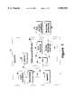
- FIG. 1is a block diagram of a monitor including features of the invention
- FIG. 2is a block diagram of a computer-based implementation of the monitor of FIG. 1;
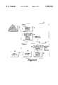
- FIG. 3illustrates typical ECG and blood pressure signals
- FIG. 4is a block diagram of the overall process of R-wave detection in response to an ECG signal and a blood pressure signal according to the invention
- FIG. 5is a flow diagram illustrating a method of implementing the first stage of R-wave detection of FIG. 4;
- FIG. 6is a flow diagram illustrating a method of implementing the second stage of R-wave detection of FIG. 4;
- FIG. 7is a block diagram of an alternative process of R-wave detection in response to an ECG signal according to the invention.
- FIG. 8is a flow diagram illustrating a method of implementing the first stage of R-wave detection of FIG. 7.
- FIG. 9is a flow diagram illustrating a method of implementing the second stage of R-wave detection of FIG. 7.
- a block diagram of a monitor 10includes a processor 14 for detecting the location of the R-waves of a patient's ECG signal, a memory 18, a display 22 and a data acquisition unit 26.
- the R-wave detection apparatus and techniques described and claimed hereinare particularly well-suited for use in heart rate variability monitors, which rely on precise R-wave detection. More generally, however, the monitor 10 detects the location of R-waves of a patient's ECG signal and it will be appreciated by those of ordinary skill in the art that the apparatus and techniques described herein are suitable for use with other types of medical monitors.
- the data acquisition unit 26includes an ECG monitor 28 and, optionally, may further include a blood pressure monitor 30.
- the ECG monitor 28operates with a conventional ECG patient interface 38, such as electrode pads adapted for attachment to a patient's chest, and includes signal processing circuitry for conditioning the measured ECG signal for further processing.
- a conventional ECG patient interface 38such as electrode pads adapted for attachment to a patient's chest
- signal processing circuitryfor conditioning the measured ECG signal for further processing.
- One suitable commercially available ECG monitoris of the type sold by Serena Medical Electronics Co., Inc. of San Jose, Calif. under the product name ECG Isolation Amplifier Module Model ECG-170.
- the output of the ECG monitor 28is an amplified ECG signal 82 which is converted into a digital signal 32 by an analog-to-digital converter 44.
- the optional blood pressure monitor 30is a conventional unit which is operative with a blood pressure patient interface 40, such as a blood pressure cuff or a pulse oximetry-type device located near an atrial line at various locations on the patient's body, such as near the heart, a finger or earlobe.
- the blood pressure monitor 30includes signal processing circuitry, such as an amplifier and filter.
- the output of the blood pressure monitor 72is an analog signal which is converted into a digital signal 32 by the analog-to-digital converter 44.
- One suitable commercially available blood pressure monitoris of the type sold by Colin Medical Instruments Corp. of San Antonio, Tex. under the product name Colin BP-508.
- the digitized ECG and blood pressure signal 32is coupled to the processor 14 for storage in the memory 18 via signal bus 34. While the illustrative monitor 10 stores digitized versions of the measured ECG and blood pressure signals (i.e., stores samples of the measured ECG and blood pressure signals), it will be appreciated by those of ordinary skill in the art that the analog ECG and blood pressure signals themselves may alternatively be stored in memory 18 for processing, including subsequent analog-to-digital conversion.
- the processor 14may take various forms, such as the microprocessor of a standard personal computer, workstation or other microprocessor-driven device.
- the processor 14is an INTEL-compatible microprocessor of an IBM-compatible personal computer running the MICROSOFT WINDOWS graphical user interface
- the memory 18includes a Random Access Memory (RAM) and the user interface 16 may include a keyboard, touch screen and/or mouse.
- the user interface 16includes a touch screen incorporated into the display 22, the display is a flat panel LCD display of the type sold by Goldstar and the processor 14 and memory 18 are typical components associated with an IBM-compatible personal computer. It will be appreciated by those of ordinary skill in the art that the apparatus and techniques of the system 10 may be implemented on various equipment, both hardware and software.
- the processorprovides additional processing including preparing the digitized signals for further time domain and spectral analysis and interfacing with the display 22 via signal line, or bus 36 to cause various data and information to be displayed to the user, including the stored ECG and blood pressure signals. Further, the detected R-wave times are used by the processor 14 to generate a heart rate variability versus time signal which is likewise displayed to the user.
- the ECG monitor 28 and/or blood pressure monitor 30may be implemented in the form of a "circuit module" adapted for insertion into an Input/Output (I/O) port or slot 21 of a standard personal computer chassis 20.
- the circuit modules 28, 30are housed in a metal or metalized-plastic box, or instrument chassis 24, which is adapted for insertion into an opening of the computer chassis 20 typically used for a diskette drive, tape drive or CD-ROM drive.
- the monitor 10may include additional circuitry (not shown) for measuring various other physiological phenomena of the patient, such as inspiration volume, in which case such circuitry is implemented in the form of one or more additional circuit modules.
- the instrument chassis 24has an open front face which permits insertion of one or more circuit module(s) therein. The front face of any unused portions of the instrument chassis is covered by metal or metalized panels.
- the instrument chassisserves as a "Gauss cage” to reduce electromagnetic interference (EMI).
- the processor 14can communicate with and control the ECG monitor module 28 and the blood pressure monitor module 30 via the computer's standard busses and the circuit modules can draw on the power available to the computer components.
- the processor 14transmits any control information to the circuit modules 28, 30 via the computer's digital control bus 42 and receives the digital ECG and blood pressure signal 32 (FIG. 1) via the computer's digital control bus 42.
- an analog-to-digital converter 54may be provided to digitize the ECG and blood pressure signal.
- FIG. 3illustrates a typical ECG signal 50 and a typical blood pressure signal 52, drawn to the same time scale.
- R-wave occurrencesare labeled 56 on the ECG signal 50 and, on the blood pressure signal 52, systoles are labeled 58 and diastoles are labeled 60.
- each diastole 60precedes an associated systole 58.
- the time scaleis in seconds, with a typical duration of a blood pressure pulse (i.e., the duration between time t 4 and t 7 ) being approximately 0.5 seconds and a typical duration of an R-wave event 56 being on the order of 0.1 seconds.
- each R-wave event 56precedes a blood pressure systole 58 by between approximately 50 and 200 milliseconds.
- the attributes of the ECG signal 50 and the blood pressure signal 52are periodic. However, the period of the features associated with these signals can and does vary in accordance with static attributes of the patient (e.g., the patient's weight) and dynamic attributes of the patient (e.g., physical exertion of the patient).
- FIG. 4a diagram illustrating one R-wave detection technique according to the invention is shown.
- a first level, or stage 70 of R-wave detectionapproximate times of systoles in the digitized blood pressure signal 72 are determined.
- a second level 80 of R-wave detectionis responsive to the digitized ECG signal 82 for providing data 92 indicative of the precise time of occurrence of R-waves in the patient's ECG signal 82.
- the blood pressure signal 72is stored in a memory buffer as illustrated by step 78.
- the memoryis accessed and a maximum signal level within a search window is detected.
- the detected maximum within a plurality of search windowscomprise the systole times as represented by output 74.
- the ECG signal 82 provided by monitor 28is filtered in step 86, such as with a lowpass filter.
- the filtered ECG signalis then stored in a memory buffer in step 88.
- an ECG window of the ECG signalis defined and searched in order to determine its maximum. It is these maxima within a plurality of ECG windows that collectively comprise the precise times of R-waves of the patient's ECG signal as represented by output 92.
- FIG. 5illustrates one technique for implementing the first stage 70 of R-wave detection of FIG. 4.
- the processcommences in step 100, following which a blood pressure signal sample and an ECG signal sample are acquired by the data acquisition unit 26 (FIG. 1) in step 104.
- the sample acquisition step 104may be performed at a predetermined frequency, such as on the order of once every millisecond.
- the ECG signal sample and the blood pressure signal sampleare, preferably, simultaneously acquired.
- the sample acquisition step 104is repeated until it is determined in step 108 that a predetermined number of blood pressure samples has been acquired.
- the predetermined number of samplesrepresents a "large search window" and the time interval represented by the large search window is selected to break down the task of processing of the blood pressure signal in order to achieve signal processing efficiencies while insuring that only a single systole occurs in each such window.
- the large search windowrepresents a time interval approximately equal to the duration of a typical blood pressure pulse (i.e., from time t 4 -t 7 in FIG. 3), such as 0.5 seconds.
- the large search window intervalmay be a predefined time interval or, alternatively, may be user selectable and/or adjustable. More particularly, the user may select the time interval of the large search window or the user may input certain information about the patient, such as the patient's body weight, in response to which the large search window interval is computed.
- a blood pressure signal sampleis selected for processing in step 112.
- the samples within the large search windoware processed to, initially, find a maximum (step 116).
- the sample selectiondefines a point in the middle of the large search window, such that there is sufficient data in memory before and after the point to determine if the point is a systole.
- the selected sampleis the sample following the sample selected during the previous iteration.
- the rise time of a blood pressure pulseis used.
- the rise timedetermines how far back signal samples must be processed in the event that the selected sample represents a systole.
- the first sample selected for processingoccurs after a time interval equal to at least the rise time of the blood pressure pulse has lapsed.
- the blood pressure pulse rise time informationmay be provided to the processor 14 in various ways.
- the userviews the blood pressure signal on the display 22, visually determines the rise time and enters this information via the user interface 16.
- the user viewing the first pulsenotes that its rise time is on the order of (t 5 -t 4 ).
- the first sample selected for processing in step 112occurs at time (t 5 -t 4 ).
- the typical rise timemay be a preselected, default value or may be user adjustable and/or selectable, such as by having the user enter certain information regarding the patient, such as the patient's age and/or body weight.
- step 116it is determined whether the selected sample is the maximum within a "small search window." Samples within a small search window are processed together in order to enhance the efficiency of signal processing.
- the selection of the time interval represented by the small search windowis a function of many factors, including the speed of the processor 14 and the frequency content of the signal (i.e., the more high-frequency noise associated with the signal, the larger the optimum small search window, in order to reduce the likelihood of false detections).
- the width of the small search windowis on the order of 0.1 seconds.
- the time interval represented by the small search windowmay be preset or, alternatively, may be user selectable and/or adjustable.
- Step 116comprises multiple iterations during each iteration of the overall process of FIG. 5.
- the way in which it is determined whether the selected sample is a maximum in the small search windowis by comparing its amplitude to that of all samples within the same window. More particularly, upon the first iteration within step 116, when the selected sample in the small search window is being processed, its amplitude is compared with the first value in the small window to determine which is greater. During the second iteration within step 116, the selected sample in the small search window is compared with the second value in the small window to determine which is greater.
- step 104the process is repeated starting with step 104, as shown. That is, if the processed sample is not a maximum in the small window, then the next sample is acquired, etc. Alternatively, if it is determined in step 116 that the selected sample is the maximum in the small search window, then the time of occurrence and amplitude of the processed sample is stored as the new maximum within the window.
- step 120it is determined whether the blood pressure signal fell by at least a predetermined amount during an interval preceding the occurrence of the maximum. In the event that the blood pressure signal did fall by at least the predetermined amount during the interval preceding the maximum, then step 124 is performed in which it is determined whether the blood pressure signal fell by at least a predetermined amount during an interval following the maximum. If both of these queries are answered in the affirmative, then a systole has been located and, in subsequent step 128, the time of the selected sample is stored as that of a systole.
- the processis repeated starting at step 104, as shown.
- steps 120 and 124are to determine whether the particular large search window in which the selected sample occurs contains a systole. For example, consider the case where the large search window extends from time t 5 -t 7 and the sample at time t 6 has been selected for processing in step 112. Processing a small search window centered at time t 6 in step 116 reveals that the sample occurring at time t 6 is the maximum within that small search window. However, it will subsequently be determined in step 120 that the blood pressure signal did not fall by a predetermined amount during an interval preceding the maximum. This determination will cause the process to be repeated since the maximum at time t 6 does not represent a systole.
- the predetermined amounts used in steps 120 and 124may be predefined values, or alternatively, may be user selectable and in both cases, are selected (either by the manufacturer or the user) in order to distinguish a systole from other artifacts in the blood pressure signal.
- the predetermined amountis a value that is selected by the user, on the order of 5 mmHg.
- the predetermined amounts of steps 120 and 124may be the same or, alternatively, may be different.
- the selectionmay be based on the user viewing the blood pressure signal and determining a value suitable for distinguishing a systole from other artifacts or, alternatively, may be based on attributes of the patient which are entered by the user, such as the patient's weight and/or age.
- step 1208Also stored in step 128, in association with the time of occurrence of each systole, is the amplitude of the systole, the time of the diastole associated with the systole, the amplitude of the diastole and the average blood pressure for the particular beat.
- determining the time of the diastole associated with a stored systolesignal samples preceding the time of each stored systole are processed.
- the time interval in which the diastole is searchedis equal to the rise time of the blood pressure pulse which is provided to the processor 14 in step 112 (FIG. 5).
- the signal samples preceding a detected systoleare processed to detect a minimum until the signal begins to climb again.
- the average blood pressure for the beatis determined by integrating the blood pressure signal over the time interval between two diastoles. Thereafter, the process terminates in step 130. However, the entire process of FIG. 5 is repeated to find each systole/diastole pair in a collected data sample.
- the second stage 80 of R-wave detection according to the method of FIG. 4is shown in FIG. 6. Recall that this stage of processing is responsive to the digitized ECG signal 82 as well as to the stored systole times generated in the first stage 70 of processing.
- the second stage 80 of processingcommences in step 140, following which an ECG window is defined in step 144.
- the ECG windowis a time interval preceding a detected systole time.
- this stepincludes the processor 14 accessing a stored systole time from memory 18 and computing a time interval preceding the stored time.
- the ECG windowrepresents a time interval during which an R-wave event 56 (FIG.
- the ECG windowthus, commences at a predetermined time prior to the stored systole time and terminates either some time before the stored systole time or at the stored systole time.
- the ECG windowcommences 250 milliseconds preceding a stored systole time and terminates 25 milliseconds before the stored systole time.
- the ECG windowmay be a predefined window (i.e., having a predefined, or default duration and time relationship to a detected systole) or, alternatively, may be user selectable and/or adjustable.
- the ECG window duration and time relationship to a systoleis computed by the processor 14 in response to certain patient information, such as the patient's size and/or the location from which the blood pressure signal is acquired (e.g., the finger or arm), which is input by the user via the user interface 16.
- patient informationsuch as the patient's size and/or the location from which the blood pressure signal is acquired (e.g., the finger or arm), which is input by the user via the user interface 16.
- step 152it is determined whether the selected ECG signal is the maximum of the samples in the ECG window. This determination is performed in an iterative manner similar to the maximum determination in step 116 of FIG. 5. That is, the amplitude of the selected sample is compared to the previously processed maximum amplitude within the window to determine whether the selected sample represents a "new" maximum. In the event that the selected sample is not the maximum in the ECG window, then step 160 is next performed, as shown. Alternatively, if the selected sample is the maximum in the ECG window, then the time of the selected sample is stored as a possible R-wave event time in step 156.
- step 160it is determined whether the processed sample is the last sample in the ECG window. If this is not the case, then step 162 is performed in which the next ECG signal sample from the ECG window is selected for processing, following which the process is repeated starting at step 152 until the last sample has been processed. Once the last sample has been selected for processing, then the time of the selected sample representing the maximum in the ECG window is stored as the time of an R-wave event in step 164. Thereafter, the process terminates in step 168.
- the precise times of R-wave eventsare determined from digitized ECG and blood pressure signals to a precision determined by the data sampling rate, for example, to within approximately 0.001 seconds for a data sampling rate of 0.001 seconds per sample.
- the first stage of processing(FIG. 5) is used to determine the times of systoles within the blood pressure signal and, this information is used in the second stage of processing (FIG. 6) to define an ECG window of the ECG signal during which the R-wave event occurs. Having defined the ECG window, samples of the ECG signal within the ECG window are processed in a manner that ensures that the precise R-wave event time is determined.
- the R-wave detection of FIG. 7is achieved without use of the patient's blood pressure signal and is responsive only to the ECG signal 82 provided by the ECG monitor 28 (FIG. 1).
- the R-wave detection of FIG. 7includes two stages of processing 170, 172. In accordance with the first stage 170, the digitized ECG signal 82 is filtered by a bandpass filter 174 to provide a filtered ECG signal 178.
- the bandpass filter 174has a nominal center frequency of 17.0 Hz and a pass band of approximately 6 Hz.
- the absolute value of the filtered ECG signal 178is calculated in step 184.
- the positive-going pulses 188may, optionally, be lowpass filtered in step 190, as shown, in order to attenuate noise due to brief episodes of 17 Hz noise to provide a further filtered signal 192.
- each of the ECG signal samplesis compared to a threshold level. If a processed signal sample exceeds the threshold level, then the time of that sample is stored as an approximate R-wave time. Alternatively, the time of the sample is not stored. Thus, the output of the comparison step 194 is a set 196 of stored times of signal samples which correspond to approximate R-wave times.
- the threshold level used in step 194may be a predetermined value and/or may have a predefined relationship to "recent" previously processed signal samples. In one embodiment, the threshold level is a predetermined percentage of the average peak values of recent signal samples.
- the threshold levelBefore a sufficient number of signal samples are processed to determine the threshold level, it may be desirable to store a short period of lowpass filtered ECG signal samples processed by steps 174 to 190 and set the threshold level to a percentage of the average peak values of the signal 192 during that period.
- the second stage 172 of R-wave detectionrelies on the approximate R-wave times provided at the output 196 of the first processing stage 170 and, further, on the digitized ECG signal 82.
- the digitized ECG signal 82is lowpass filtered in a step 200, preferably by a filter that preserves time-domain content of the signal, such as a filter having an "elliptical" response.
- the filtered signal samples 202are stored in memory in step 206.
- the approximate R-wave times 196 provided by the first stage 170 of R-wave detectionare used to define an ECG window within the filtered signal portion stored in step 206 for processing to determine the precise times of R-waves.
- an ECG windowis defined to have a predetermined time relationship with respect to each approximate R-wave time and a predetermined duration.
- the stored samplesare accessed and processed in groups defined by ECG windows which have a predetermined time relationship with respect to the approximate R-wave times determined in stage 170.
- the maximum signal sample within each ECG windowyields a precise R-wave time at the output 214 of the second stage 172 of R-wave detection.
- FIG. 7illustrates a method of implementing the first stage 170 of R-wave detection
- FIG. 9illustrates a method of implementing the second stage 172 of R-wave detection.
- step 220the process commences in step 220, following which an ECG signal sample is acquired by the data acquisition unit 26 (FIG. 1) in step 224.
- step 226the acquired ECG signal sample is stored in a raw data array.
- step 228, the stored ECG signal sampleis bandpass filtered.
- Various apparatus and methodsare suitable for filtering the ECG signal sample in step 228, including a software filter.
- step 232the absolute value of the processed signal sample is computed, to ensure that all pulses are positive-going.
- the samplemay be lowpass filtered in step 234.
- step 236the processed signal sample is stored in a processed data array.
- process step 2308it is determined whether a predetermined number of ECG signal samples have been acquired.
- the predetermined numberis associated with an ECG signal processing window of sufficient width to contain an R-wave event.
- the predetermined number of samplesare those acquired within an interval on the order of 0.2 seconds.
- step 250it is determined in step 250 whether data collection has been completed. If data collection has been completed, then the process terminates in step 256. Alternatively, the process is repeated, starting with acquisition of another ECG signal sample in step 224, as shown.
- the next sample in the ECG windowis selected for processing in step 240 and, it is next determined in process step 242 whether the selected sample exceeds a threshold level.
- the selected sampleprecedes the most recently acquired sample by a predetermined time.
- each processed sampleis compared to the threshold level to determine whether the sample exceeds the threshold and thus, is indicative of an approximate R-wave time.
- the threshold levelmay be a predefined, or predetermined level, it may be a function of the amplitude of certain ECG signal samples or it may be user selectable or adjustable.
- the threshold levelis a predetermined percentage of the average peak values of a predetermined number of recently processed (steps 224 through 236) ECG signal samples.
- a suitable number of ECG signal samples from which to compute the threshold valueis on the order of five or more and the predetermined percentage of the average peak values is on the order of 30%.
- the predetermined number of ECG signal samples on which to base the threshold levelwill not yet have been processed. During this time, a predetermined threshold level may be used or processing may be delayed until after the predetermined number of samples have been accumulated.
- step 250is next performed, as shown.
- step 244it is next determined in step 244 whether a lockout time interval has lapsed since the last detection of a selected sample exceeding the threshold.
- the lockout time intervalis selected to prevent noise from causing false R-wave detections.
- the lockout time intervalis on the order of 0.2 seconds.
- the processis repeated starting at step 250.
- the time of occurrence of the selected sampleis stored in step 248 as the approximate time of an R-wave event, following which step 250 is repeated.
- the second stage 172 of R-wave detectioncommences in step 260, following which an ECG window is defined in step 262.
- the ECG windowis a portion of the digitized and stored ECG signal during which an R-wave event is expected to occur.
- the ECG windowhas a predefined time relationship centered around an approximate R-wave location stored in step 248 of FIG. 8 and a duration on the order of 0.15 seconds. It will be appreciated by those of ordinary skill in the art however, that more generally, the ECG window may be defined in other manners and, in fact, may be user selectable in terms of its duration and relationship to an approximate R-wave time stored in step 248.
- step 264the first sample of the digitized ECG signal in the ECG window is selected for processing. Thereafter, in step 266, it is determined whether the selected sample is the maximum of the samples that have been processed within the ECG window. As discussed previously, this determination is made by comparing the selected sample with the previously processed signal sample having the greatest amplitude in the ECG window.
- step 270is next performed in which it is determined whether the selected sample is the last sample of the ECG window. Alternatively, the time of the selected sample is stored in step 268 as the time of a possible R-wave event. In step 270, if it is determined that the selected sample is not the last sample within the ECG window, then step 272 is performed in which the next ECG sample from the ECG window is selected for processing, following which the process is repeated starting at step 266, as shown. Alternatively, the time of the selected sample is stored as the time of an R-wave event in step 274, following which the process terminates in step 276.
- the embodiments of the present inventioninclude defining a relatively narrow ECG window of the ECG signal in which the R-wave events occur.
- the samples within the defined ECG windowsare processed in a manner which provides a precise determination of R-wave events.
- the precision of the R-wave event detectionis made possible by the definition and precise processing within the relatively narrow ECG windows in which R-wave events occur, since such precise processing of the entire ECG signal is computationally intensive and more liable to be affected by artifacts, such as noise, lead movement, muscle movement, etc.
Landscapes
- Health & Medical Sciences (AREA)
- Life Sciences & Earth Sciences (AREA)
- Cardiology (AREA)
- Heart & Thoracic Surgery (AREA)
- Molecular Biology (AREA)
- Pathology (AREA)
- Engineering & Computer Science (AREA)
- Biomedical Technology (AREA)
- Physics & Mathematics (AREA)
- Medical Informatics (AREA)
- Biophysics (AREA)
- Surgery (AREA)
- Animal Behavior & Ethology (AREA)
- General Health & Medical Sciences (AREA)
- Public Health (AREA)
- Veterinary Medicine (AREA)
- Measuring Pulse, Heart Rate, Blood Pressure Or Blood Flow (AREA)
Abstract
Description
Claims (13)
Priority Applications (6)
| Application Number | Priority Date | Filing Date | Title |
|---|---|---|---|
| US08/940,396US5984954A (en) | 1997-10-01 | 1997-10-01 | Methods and apparatus for R-wave detection |
| EP98951976AEP1026986A1 (en) | 1997-10-01 | 1998-09-29 | Methods and apparatus for r-wave detection |
| CA002304467ACA2304467A1 (en) | 1997-10-01 | 1998-09-29 | Methods and apparatus for r-wave detection |
| PCT/US1998/020323WO1999016351A1 (en) | 1997-10-01 | 1998-09-29 | Methods and apparatus for r-wave detection |
| JP2000513498AJP2001517520A (en) | 1997-10-01 | 1998-09-29 | R wave detection method and apparatus |
| US09/426,509US6161037A (en) | 1997-10-01 | 1999-10-26 | Methods and apparatus for R-wave detection |
Applications Claiming Priority (1)
| Application Number | Priority Date | Filing Date | Title |
|---|---|---|---|
| US08/940,396US5984954A (en) | 1997-10-01 | 1997-10-01 | Methods and apparatus for R-wave detection |
Related Child Applications (1)
| Application Number | Title | Priority Date | Filing Date |
|---|---|---|---|
| US09/426,509DivisionUS6161037A (en) | 1997-10-01 | 1999-10-26 | Methods and apparatus for R-wave detection |
Publications (1)
| Publication Number | Publication Date |
|---|---|
| US5984954Atrue US5984954A (en) | 1999-11-16 |
Family
ID=25474752
Family Applications (2)
| Application Number | Title | Priority Date | Filing Date |
|---|---|---|---|
| US08/940,396Expired - Fee RelatedUS5984954A (en) | 1997-10-01 | 1997-10-01 | Methods and apparatus for R-wave detection |
| US09/426,509Expired - Fee RelatedUS6161037A (en) | 1997-10-01 | 1999-10-26 | Methods and apparatus for R-wave detection |
Family Applications After (1)
| Application Number | Title | Priority Date | Filing Date |
|---|---|---|---|
| US09/426,509Expired - Fee RelatedUS6161037A (en) | 1997-10-01 | 1999-10-26 | Methods and apparatus for R-wave detection |
Country Status (5)
| Country | Link |
|---|---|
| US (2) | US5984954A (en) |
| EP (1) | EP1026986A1 (en) |
| JP (1) | JP2001517520A (en) |
| CA (1) | CA2304467A1 (en) |
| WO (1) | WO1999016351A1 (en) |
Cited By (19)
| Publication number | Priority date | Publication date | Assignee | Title |
|---|---|---|---|---|
| WO2002000112A2 (en) | 2000-06-26 | 2002-01-03 | Boston Medical Technologies, Inc. | Glucose metering system |
| US6434417B1 (en) | 2000-03-28 | 2002-08-13 | Cardiac Pacemakers, Inc. | Method and system for detecting cardiac depolarization |
| US20040219600A1 (en)* | 2002-12-13 | 2004-11-04 | Williams Robert Wood | Method for determining sensitivity to environmental toxins and susceptibility to parkinson's disease |
| US20050059880A1 (en)* | 2003-09-11 | 2005-03-17 | Mathias Sanjay George | ECG driven image reconstruction for cardiac imaging |
| US20050251057A1 (en)* | 2004-05-10 | 2005-11-10 | Medpond, Llc | Method and apparatus for facilitating the provision of healthcare services |
| US20050251051A1 (en)* | 2004-05-10 | 2005-11-10 | Medpond, Llc | Method and apparatus for assessing autonomic function |
| US20060036263A1 (en)* | 1998-07-27 | 2006-02-16 | Schneider (Usa) Inc. | Neuroaneurysm occlusion and delivery device and method of using same |
| US7031765B2 (en) | 2002-11-11 | 2006-04-18 | Medtronic, Inc | Algorithms for detecting atrial arrhythmias from discriminatory signatures of ventricular cycle lengths |
| US20070021680A1 (en)* | 2005-07-22 | 2007-01-25 | Transoma Medical, Inc. | Methods to reduce power to measure pressure |
| US7289845B2 (en) | 2000-10-31 | 2007-10-30 | Cardiac Pacemakers, Inc. | Curvature based method for selecting features from an electrophysiologic signal for purpose of complex identification and classification |
| US20090264774A1 (en)* | 2005-10-07 | 2009-10-22 | Akira Kondo | Blood Pressure Measuring Cuffs and a Blood Pressure Measuring Device |
| US7610084B2 (en) | 2001-06-05 | 2009-10-27 | Cardiac Pacemakers, Inc. | System and method for classifying cardiac depolarization complexes with multi-dimensional correlation |
| US20100114228A1 (en)* | 2008-11-03 | 2010-05-06 | Pacesetter, Inc. | System and method for accurately detecting cardiac events using retrospective correlation |
| US20110319780A1 (en)* | 2010-06-24 | 2011-12-29 | Michael Frank | Method for identifying a characteristic profile of an R-wave in an EKG signal and a computer program product as well as an electronically readable data medium for performing the method |
| US8409107B2 (en) | 2003-06-27 | 2013-04-02 | Cardiac Pacemakers, Inc. | Tachyarrhythmia detection and discrimination based on curvature parameters |
| US20140309540A1 (en)* | 2012-07-06 | 2014-10-16 | Panasonic Corporation | Biosignal measurement apparatus and biosignal measurement method |
| CN111345812A (en)* | 2018-12-24 | 2020-06-30 | Zoll医疗公司 | R wave detection method and device, and computer readable storage medium |
| US20220020186A1 (en)* | 2017-11-06 | 2022-01-20 | Shanghai United Imaging Healthcare Co., Ltd. | Systems and methods for medical imaging |
| JP2023139471A (en)* | 2022-03-22 | 2023-10-04 | トヨタ自動車株式会社 | Detection apparatus, detection method, and detection program |
Families Citing this family (12)
| Publication number | Priority date | Publication date | Assignee | Title |
|---|---|---|---|---|
| US6556862B2 (en) | 1998-03-19 | 2003-04-29 | Cardiac Pacemakers, Inc. | Method and apparatus for treating supraventricular tachyarrhythmias |
| US6580948B2 (en)* | 2000-04-25 | 2003-06-17 | Medtronic, Inc. | Interface devices for instruments in communication with implantable medical devices |
| US6847842B1 (en) | 2000-05-15 | 2005-01-25 | Cardiac Pacemakers, Inc. | Method and apparatus for reducing early recurrence of atrial fibrillation with defibrillation shock therapy |
| FR2821460B1 (en)* | 2001-02-28 | 2003-06-27 | Chru Lille | METHOD AND DEVICE FOR FILTERING AN RR SERIES FROM A CARDIAC SIGNAL, ESPECIALLY AN ECG SIGNAL |
| US6584350B2 (en)* | 2001-04-06 | 2003-06-24 | Cardiac Pacemakers, Inc. | Apparatus and method for R-wave detection with dual dynamic sensitivities |
| US6862472B2 (en)* | 2001-07-26 | 2005-03-01 | Ge Medical Systems Information Technologies, Inc. | Medical testing system with an illuminating component |
| JP5826984B2 (en)* | 2007-01-12 | 2015-12-02 | 株式会社東芝 | Ultrasonic diagnostic apparatus, heart rate synchronization signal generation apparatus, and heart rate synchronization signal generation method |
| US8755875B2 (en) | 2008-05-09 | 2014-06-17 | Siemens Medical Solutions Usa, Inc. | System for heart performance characterization and abnormality detection |
| GB0905377D0 (en) | 2009-03-30 | 2009-05-13 | Danmedical Ltd | Medical apparatus |
| EP2510974B1 (en) | 2011-04-15 | 2013-12-25 | Sorin CRM SAS | Active medical device, in particular an implantable defibrillator, with detection of QRS complexes in a signal with a lot of interference |
| US11096618B2 (en)* | 2016-12-06 | 2021-08-24 | Nippon Telegraph And Telephone Corporation | Signal feature extraction apparatus, signal feature extraction method, and program |
| KR102080113B1 (en)* | 2018-05-14 | 2020-02-21 | 전문석 | Apparatus and method for calculating blood pressure using digital electrocardiogram voltage coordinate values |
Citations (78)
| Publication number | Priority date | Publication date | Assignee | Title |
|---|---|---|---|---|
| US2649573A (en)* | 1948-12-21 | 1953-08-18 | Harold D Goldberg | Area measuring device |
| US3142796A (en)* | 1953-08-18 | 1964-07-28 | Harold D Goldberg | Method and apparatus utilizing a conductor loop in a magnetic field for measuring areas and related quantities |
| US3340867A (en)* | 1964-08-19 | 1967-09-12 | Univ Minnesota | Impedance plethysmograph |
| US3407818A (en)* | 1966-10-10 | 1968-10-29 | Raphael J. Costanzo | Electrical heating belt |
| US3560845A (en)* | 1965-05-03 | 1971-02-02 | Harold D Goldberg | Measuring devices |
| US3731184A (en)* | 1948-12-21 | 1973-05-01 | H Goldberg | Deformable pick up coil and cooperating magnet for measuring physical quantities, with means for rendering coil output independent of orientation |
| US3925762A (en)* | 1973-10-25 | 1975-12-09 | Gen Electric | Patient monitoring and data processing system |
| US3991304A (en)* | 1975-05-19 | 1976-11-09 | Hillsman Dean | Respiratory biofeedback and performance evaluation system |
| US4023563A (en)* | 1975-09-22 | 1977-05-17 | American Home Products Corporation | Apparatus and method for determining onset times of pulses and use thereof in computing interarterial blood pressure electromechanical interval |
| US4031885A (en)* | 1975-10-15 | 1977-06-28 | Puritan-Bennett Corporation | Method and apparatus for determining patient lung pressure, compliance and resistance |
| US4036215A (en)* | 1975-02-06 | 1977-07-19 | Doll Research, Inc. | Apparatus and method for eliminating perturbations of a kinetic origin in the blood flow waveform |
| US4137910A (en)* | 1976-09-30 | 1979-02-06 | Murphy Donald H | Method and means for measuring cardiac pumping performance of left ventricle |
| US4216779A (en)* | 1977-05-16 | 1980-08-12 | Del Mar Avionics | Blood pressure monitoring system |
| US4240442A (en)* | 1979-01-05 | 1980-12-23 | American Optical Corporation | Variable threshold R-wave detector |
| US4308872A (en)* | 1977-04-07 | 1982-01-05 | Respitrace Corporation | Method and apparatus for monitoring respiration |
| US4346718A (en)* | 1978-02-22 | 1982-08-31 | Oxford Medical Systems Limited | Apparatus and methods for recording time intervals |
| US4364397A (en)* | 1980-01-23 | 1982-12-21 | Medtronic, Inc. | Apparatus for monitoring the rhythm of a patient's heartbeat |
| US4367753A (en)* | 1980-01-23 | 1983-01-11 | Medtronic Inc. | Apparatus for monitoring and storing heartbeats of a patient |
| GB2113101A (en)* | 1981-12-15 | 1983-08-03 | Medizin Labortechnik Veb K | Breathing apparatus |
| US4408614A (en)* | 1981-07-06 | 1983-10-11 | Sri International | Blood pressure measurement with Korotkov sound artifact information detection and rejection |
| US4433693A (en)* | 1979-09-27 | 1984-02-28 | Hochstein Peter A | Method and assembly for monitoring respiration and detecting apnea |
| US4440177A (en)* | 1980-07-03 | 1984-04-03 | Medical Graphics Corporation | Respiratory analyzer system |
| US4446872A (en)* | 1977-09-08 | 1984-05-08 | Avl Ag | Method and apparatus for determining systolic time intervals |
| US4506678A (en)* | 1982-06-07 | 1985-03-26 | Healthdyne, Inc. | Patient monitor for providing respiration and electrocardiogram signals |
| US4513295A (en)* | 1983-10-21 | 1985-04-23 | American Home Products Corporation (Del.) | Method for recording medical information on a strip chart |
| US4559947A (en)* | 1984-01-27 | 1985-12-24 | Renger Herman L | Cardiac tissue stimulator providing P-wave verification, telemetry, marker channels, and antitachycardia capabilities |
| US4589420A (en)* | 1984-07-13 | 1986-05-20 | Spacelabs Inc. | Method and apparatus for ECG rhythm analysis |
| US4649929A (en)* | 1981-06-11 | 1987-03-17 | Sri International | Method and apparatus for diagnosis of coronary artery disease |
| US4679144A (en)* | 1984-08-21 | 1987-07-07 | Q-Med, Inc. | Cardiac signal real time monitor and method of analysis |
| US4692148A (en)* | 1986-03-28 | 1987-09-08 | Aisin Seiki Kabushiki Kaisha | Intra-aortic balloon pump apparatus and method of using same |
| US4721114A (en)* | 1986-02-21 | 1988-01-26 | Cardiac Pacemakers, Inc. | Method of detecting P-waves in ECG recordings |
| US4777960A (en)* | 1986-08-18 | 1988-10-18 | Massachusetts Institute Of Technology | Method and apparatus for the assessment of autonomic response by broad-band excitation |
| US4807640A (en)* | 1986-11-19 | 1989-02-28 | Respitrace Corporation | Stretchable band-type transducer particularly suited for respiration monitoring apparatus |
| US4819654A (en)* | 1981-06-11 | 1989-04-11 | Sri International | Method and apparatus for diagnosis of coronary artery disease |
| US4832038A (en)* | 1985-06-05 | 1989-05-23 | The Board Of Trustees Of University Of Illinois | Apparatus for monitoring cardiovascular regulation using heart rate power spectral analysis |
| US4862361A (en)* | 1985-06-05 | 1989-08-29 | Massachusetts Institute Of Technology | Methods and apparatus for monitoring cardiovascular regulation using heart rate power spectral analysis |
| US4869262A (en)* | 1987-02-02 | 1989-09-26 | Pulse Time Products Limited | Device for displaying blood pressure |
| US4870974A (en)* | 1987-09-30 | 1989-10-03 | Chinese Pla General Hospital | Apparatus and method for detecting heart characteristics by way of electrical stimulation |
| US4889131A (en)* | 1987-12-03 | 1989-12-26 | American Health Products, Inc. | Portable belt monitor of physiological functions and sensors therefor |
| US4905708A (en)* | 1985-10-31 | 1990-03-06 | Davies David W | Apparatus for recognizing cardiac rhythms |
| US4909260A (en)* | 1987-12-03 | 1990-03-20 | American Health Products, Inc. | Portable belt monitor of physiological functions and sensors therefor |
| US4913146A (en)* | 1987-10-13 | 1990-04-03 | Telectronics Pacing Systems Inc. | Cardiac sense amplifier with pattern recognition capabilities |
| US4930517A (en)* | 1989-04-25 | 1990-06-05 | Massachusetts Institute Of Technology | Method and apparatus for physiologic system identification |
| US4934377A (en)* | 1987-11-24 | 1990-06-19 | The Cleveland Clinic Foundation | Intraoperative neuroelectrophysiological monitoring system |
| US4947857A (en)* | 1989-02-01 | 1990-08-14 | Corazonix Corporation | Method and apparatus for analyzing and interpreting electrocardiograms using spectro-temporal mapping |
| US4974597A (en)* | 1988-10-05 | 1990-12-04 | Spacelabs, Inc. | Apparatus for identifying artifact in automatic blood pressure measurements |
| US4979110A (en)* | 1988-09-22 | 1990-12-18 | Massachusetts Institute Of Technology | Characterizing the statistical properties of a biological signal |
| US4984158A (en)* | 1988-10-14 | 1991-01-08 | Hillsman Dean | Metered dose inhaler biofeedback training and evaluation system |
| US5025794A (en)* | 1988-08-30 | 1991-06-25 | Corazonix Corporation | Method for analysis of electrocardiographic signal QRS complex |
| US5027824A (en)* | 1989-12-01 | 1991-07-02 | Edmond Dougherty | Method and apparatus for detecting, analyzing and recording cardiac rhythm disturbances |
| US5148812A (en)* | 1991-02-20 | 1992-09-22 | Georgetown University | Non-invasive dynamic tracking of cardiac vulnerability by analysis of t-wave alternans |
| US5156148A (en)* | 1987-10-06 | 1992-10-20 | Leonard Bloom | System for treating a malfunctioning heart |
| US5159935A (en)* | 1990-03-08 | 1992-11-03 | Nims, Inc. | Non-invasive estimation of individual lung function |
| US5167506A (en)* | 1991-10-24 | 1992-12-01 | Minnesota Mining And Manufacturing Company | Inhalation device training system |
| US5269301A (en)* | 1987-10-06 | 1993-12-14 | Leonard Bloom | Multimode system for monitoring and treating a malfunctioning heart |
| US5277189A (en)* | 1991-08-16 | 1994-01-11 | Nid, Inc. | Method and apparatus for the measurement and analysis of cardiac rates and amplitude variations |
| US5285793A (en)* | 1992-05-21 | 1994-02-15 | Regents Of The Univeristy Of Minnesota | Noninvasive detection of rejection in heart transplant patients |
| US5299119A (en)* | 1989-07-06 | 1994-03-29 | Qmed, Inc. | Autonomic neuropathy detection and method of analysis |
| US5301678A (en)* | 1986-11-19 | 1994-04-12 | Non-Invasive Monitoring System, Inc. | Stretchable band - type transducer particularly suited for use with respiration monitoring apparatus |
| US5312441A (en)* | 1992-04-13 | 1994-05-17 | Medtronic, Inc. | Method and apparatus for discrimination of ventricular tachycardia from supraventricular tachycardia and for treatment thereof |
| US5316008A (en)* | 1990-04-06 | 1994-05-31 | Casio Computer Co., Ltd. | Measurement of electrocardiographic wave and sphygmus |
| US5330508A (en)* | 1993-03-02 | 1994-07-19 | Medtronic, Inc. | Apparatus for detection and treatment of tachycardia and fibrillation |
| US5333106A (en)* | 1992-10-09 | 1994-07-26 | Circadian, Inc. | Apparatus and visual display method for training in the power use of aerosol pharmaceutical inhalers |
| US5339822A (en)* | 1991-05-07 | 1994-08-23 | Protocol Systems, Inc. | Method of validating physiologic events resulting from a heartbeat |
| US5360008A (en)* | 1992-11-18 | 1994-11-01 | Campbell Jr William G | Respiratory and cardiac monitor |
| US5390679A (en)* | 1993-06-03 | 1995-02-21 | Eli Lilly And Company | Continuous cardiac output derived from the arterial pressure waveform using pattern recognition |
| US5394873A (en)* | 1990-11-23 | 1995-03-07 | Odam, S.A. | Monitor for surveying the vital physiological parameters of a patient undergoing NMR imaging |
| US5400795A (en)* | 1993-10-22 | 1995-03-28 | Telectronics Pacing Systems, Inc. | Method of classifying heart rhythms by analyzing several morphology defining metrics derived for a patient's QRS complex |
| US5423325A (en)* | 1993-03-12 | 1995-06-13 | Hewlett-Packard Corporation | Methods for enhancement of HRV and late potentials measurements |
| US5437285A (en)* | 1991-02-20 | 1995-08-01 | Georgetown University | Method and apparatus for prediction of sudden cardiac death by simultaneous assessment of autonomic function and cardiac electrical stability |
| US5450850A (en)* | 1993-11-05 | 1995-09-19 | Kabushiki Kaisha Toshiba | System for examining cardiac function |
| US5485847A (en)* | 1993-10-08 | 1996-01-23 | Nellcor Puritan Bennett Incorporated | Pulse oximeter using a virtual trigger for heart rate synchronization |
| US5497778A (en)* | 1993-06-30 | 1996-03-12 | Hon; Edward H. | Apparatus and method for noninvasive measurement of peripheral pressure pulse compliance and systolic time intervals |
| US5509404A (en)* | 1994-07-11 | 1996-04-23 | Aradigm Corporation | Intrapulmonary drug delivery within therapeutically relevant inspiratory flow/volume values |
| US5520190A (en)* | 1994-10-31 | 1996-05-28 | Ventritex, Inc. | Cardiac blood flow sensor and method |
| US5570696A (en)* | 1994-01-26 | 1996-11-05 | Cambridge Heart, Inc. | Method and apparatus for assessing myocardial electrical stability |
| WO1997012546A1 (en)* | 1995-10-05 | 1997-04-10 | Massachusetts Institute Of Technology | Method and apparatus for assessing cardiovascular risk |
| US5724580A (en)* | 1995-03-31 | 1998-03-03 | Qmed, Inc. | System and method of generating prognosis and therapy reports for coronary health management |
Family Cites Families (1)
| Publication number | Priority date | Publication date | Assignee | Title |
|---|---|---|---|---|
| SU1391616A1 (en)* | 1986-03-20 | 1988-04-30 | Особое Конструкторское Бюро Биологической И Медицинской Кибернетики Ленинградского Электротехнического Института Им.В.И.Ульянова (Ленина) | Apparatus for separating r-wave of electrocardio signal |
- 1997
- 1997-10-01USUS08/940,396patent/US5984954A/ennot_activeExpired - Fee Related
- 1998
- 1998-09-29WOPCT/US1998/020323patent/WO1999016351A1/ennot_activeApplication Discontinuation
- 1998-09-29CACA002304467Apatent/CA2304467A1/ennot_activeAbandoned
- 1998-09-29JPJP2000513498Apatent/JP2001517520A/ennot_activeWithdrawn
- 1998-09-29EPEP98951976Apatent/EP1026986A1/ennot_activeWithdrawn
- 1999
- 1999-10-26USUS09/426,509patent/US6161037A/ennot_activeExpired - Fee Related
Patent Citations (79)
| Publication number | Priority date | Publication date | Assignee | Title |
|---|---|---|---|---|
| US3731184A (en)* | 1948-12-21 | 1973-05-01 | H Goldberg | Deformable pick up coil and cooperating magnet for measuring physical quantities, with means for rendering coil output independent of orientation |
| US2649573A (en)* | 1948-12-21 | 1953-08-18 | Harold D Goldberg | Area measuring device |
| US3142796A (en)* | 1953-08-18 | 1964-07-28 | Harold D Goldberg | Method and apparatus utilizing a conductor loop in a magnetic field for measuring areas and related quantities |
| US3340867A (en)* | 1964-08-19 | 1967-09-12 | Univ Minnesota | Impedance plethysmograph |
| US3560845A (en)* | 1965-05-03 | 1971-02-02 | Harold D Goldberg | Measuring devices |
| US3407818A (en)* | 1966-10-10 | 1968-10-29 | Raphael J. Costanzo | Electrical heating belt |
| US3925762A (en)* | 1973-10-25 | 1975-12-09 | Gen Electric | Patient monitoring and data processing system |
| US4036215A (en)* | 1975-02-06 | 1977-07-19 | Doll Research, Inc. | Apparatus and method for eliminating perturbations of a kinetic origin in the blood flow waveform |
| US3991304A (en)* | 1975-05-19 | 1976-11-09 | Hillsman Dean | Respiratory biofeedback and performance evaluation system |
| US4023563A (en)* | 1975-09-22 | 1977-05-17 | American Home Products Corporation | Apparatus and method for determining onset times of pulses and use thereof in computing interarterial blood pressure electromechanical interval |
| US4031885A (en)* | 1975-10-15 | 1977-06-28 | Puritan-Bennett Corporation | Method and apparatus for determining patient lung pressure, compliance and resistance |
| US4137910A (en)* | 1976-09-30 | 1979-02-06 | Murphy Donald H | Method and means for measuring cardiac pumping performance of left ventricle |
| US4308872A (en)* | 1977-04-07 | 1982-01-05 | Respitrace Corporation | Method and apparatus for monitoring respiration |
| US4216779A (en)* | 1977-05-16 | 1980-08-12 | Del Mar Avionics | Blood pressure monitoring system |
| US4446872A (en)* | 1977-09-08 | 1984-05-08 | Avl Ag | Method and apparatus for determining systolic time intervals |
| US4346718A (en)* | 1978-02-22 | 1982-08-31 | Oxford Medical Systems Limited | Apparatus and methods for recording time intervals |
| US4240442A (en)* | 1979-01-05 | 1980-12-23 | American Optical Corporation | Variable threshold R-wave detector |
| US4433693A (en)* | 1979-09-27 | 1984-02-28 | Hochstein Peter A | Method and assembly for monitoring respiration and detecting apnea |
| US4364397A (en)* | 1980-01-23 | 1982-12-21 | Medtronic, Inc. | Apparatus for monitoring the rhythm of a patient's heartbeat |
| US4367753A (en)* | 1980-01-23 | 1983-01-11 | Medtronic Inc. | Apparatus for monitoring and storing heartbeats of a patient |
| US4440177A (en)* | 1980-07-03 | 1984-04-03 | Medical Graphics Corporation | Respiratory analyzer system |
| US4649929A (en)* | 1981-06-11 | 1987-03-17 | Sri International | Method and apparatus for diagnosis of coronary artery disease |
| US4819654A (en)* | 1981-06-11 | 1989-04-11 | Sri International | Method and apparatus for diagnosis of coronary artery disease |
| US4408614A (en)* | 1981-07-06 | 1983-10-11 | Sri International | Blood pressure measurement with Korotkov sound artifact information detection and rejection |
| GB2113101A (en)* | 1981-12-15 | 1983-08-03 | Medizin Labortechnik Veb K | Breathing apparatus |
| US4506678A (en)* | 1982-06-07 | 1985-03-26 | Healthdyne, Inc. | Patient monitor for providing respiration and electrocardiogram signals |
| US4513295A (en)* | 1983-10-21 | 1985-04-23 | American Home Products Corporation (Del.) | Method for recording medical information on a strip chart |
| US4559947A (en)* | 1984-01-27 | 1985-12-24 | Renger Herman L | Cardiac tissue stimulator providing P-wave verification, telemetry, marker channels, and antitachycardia capabilities |
| US4589420A (en)* | 1984-07-13 | 1986-05-20 | Spacelabs Inc. | Method and apparatus for ECG rhythm analysis |
| US4679144A (en)* | 1984-08-21 | 1987-07-07 | Q-Med, Inc. | Cardiac signal real time monitor and method of analysis |
| US4832038A (en)* | 1985-06-05 | 1989-05-23 | The Board Of Trustees Of University Of Illinois | Apparatus for monitoring cardiovascular regulation using heart rate power spectral analysis |
| US4862361A (en)* | 1985-06-05 | 1989-08-29 | Massachusetts Institute Of Technology | Methods and apparatus for monitoring cardiovascular regulation using heart rate power spectral analysis |
| US4905708A (en)* | 1985-10-31 | 1990-03-06 | Davies David W | Apparatus for recognizing cardiac rhythms |
| US4721114A (en)* | 1986-02-21 | 1988-01-26 | Cardiac Pacemakers, Inc. | Method of detecting P-waves in ECG recordings |
| US4692148A (en)* | 1986-03-28 | 1987-09-08 | Aisin Seiki Kabushiki Kaisha | Intra-aortic balloon pump apparatus and method of using same |
| US4777960A (en)* | 1986-08-18 | 1988-10-18 | Massachusetts Institute Of Technology | Method and apparatus for the assessment of autonomic response by broad-band excitation |
| US4807640A (en)* | 1986-11-19 | 1989-02-28 | Respitrace Corporation | Stretchable band-type transducer particularly suited for respiration monitoring apparatus |
| US5301678A (en)* | 1986-11-19 | 1994-04-12 | Non-Invasive Monitoring System, Inc. | Stretchable band - type transducer particularly suited for use with respiration monitoring apparatus |
| US5543012A (en)* | 1986-11-19 | 1996-08-06 | Non-Invasive Monitoring Systems, Inc. | Apparatus for making a stretchable band-type transducer particularly suited for use with respiration monitoring apparatus |
| US4869262A (en)* | 1987-02-02 | 1989-09-26 | Pulse Time Products Limited | Device for displaying blood pressure |
| US4870974A (en)* | 1987-09-30 | 1989-10-03 | Chinese Pla General Hospital | Apparatus and method for detecting heart characteristics by way of electrical stimulation |
| US5156148A (en)* | 1987-10-06 | 1992-10-20 | Leonard Bloom | System for treating a malfunctioning heart |
| US5269301A (en)* | 1987-10-06 | 1993-12-14 | Leonard Bloom | Multimode system for monitoring and treating a malfunctioning heart |
| US4913146A (en)* | 1987-10-13 | 1990-04-03 | Telectronics Pacing Systems Inc. | Cardiac sense amplifier with pattern recognition capabilities |
| US4934377A (en)* | 1987-11-24 | 1990-06-19 | The Cleveland Clinic Foundation | Intraoperative neuroelectrophysiological monitoring system |
| US4889131A (en)* | 1987-12-03 | 1989-12-26 | American Health Products, Inc. | Portable belt monitor of physiological functions and sensors therefor |
| US4909260A (en)* | 1987-12-03 | 1990-03-20 | American Health Products, Inc. | Portable belt monitor of physiological functions and sensors therefor |
| US5025794A (en)* | 1988-08-30 | 1991-06-25 | Corazonix Corporation | Method for analysis of electrocardiographic signal QRS complex |
| US4979110A (en)* | 1988-09-22 | 1990-12-18 | Massachusetts Institute Of Technology | Characterizing the statistical properties of a biological signal |
| US4974597A (en)* | 1988-10-05 | 1990-12-04 | Spacelabs, Inc. | Apparatus for identifying artifact in automatic blood pressure measurements |
| US4984158A (en)* | 1988-10-14 | 1991-01-08 | Hillsman Dean | Metered dose inhaler biofeedback training and evaluation system |
| US4947857A (en)* | 1989-02-01 | 1990-08-14 | Corazonix Corporation | Method and apparatus for analyzing and interpreting electrocardiograms using spectro-temporal mapping |
| US4930517A (en)* | 1989-04-25 | 1990-06-05 | Massachusetts Institute Of Technology | Method and apparatus for physiologic system identification |
| US5299119A (en)* | 1989-07-06 | 1994-03-29 | Qmed, Inc. | Autonomic neuropathy detection and method of analysis |
| US5027824A (en)* | 1989-12-01 | 1991-07-02 | Edmond Dougherty | Method and apparatus for detecting, analyzing and recording cardiac rhythm disturbances |
| US5159935A (en)* | 1990-03-08 | 1992-11-03 | Nims, Inc. | Non-invasive estimation of individual lung function |
| US5316008A (en)* | 1990-04-06 | 1994-05-31 | Casio Computer Co., Ltd. | Measurement of electrocardiographic wave and sphygmus |
| US5394873A (en)* | 1990-11-23 | 1995-03-07 | Odam, S.A. | Monitor for surveying the vital physiological parameters of a patient undergoing NMR imaging |
| US5148812A (en)* | 1991-02-20 | 1992-09-22 | Georgetown University | Non-invasive dynamic tracking of cardiac vulnerability by analysis of t-wave alternans |
| US5437285A (en)* | 1991-02-20 | 1995-08-01 | Georgetown University | Method and apparatus for prediction of sudden cardiac death by simultaneous assessment of autonomic function and cardiac electrical stability |
| US5339822A (en)* | 1991-05-07 | 1994-08-23 | Protocol Systems, Inc. | Method of validating physiologic events resulting from a heartbeat |
| US5277189A (en)* | 1991-08-16 | 1994-01-11 | Nid, Inc. | Method and apparatus for the measurement and analysis of cardiac rates and amplitude variations |
| US5167506A (en)* | 1991-10-24 | 1992-12-01 | Minnesota Mining And Manufacturing Company | Inhalation device training system |
| US5312441A (en)* | 1992-04-13 | 1994-05-17 | Medtronic, Inc. | Method and apparatus for discrimination of ventricular tachycardia from supraventricular tachycardia and for treatment thereof |
| US5285793A (en)* | 1992-05-21 | 1994-02-15 | Regents Of The Univeristy Of Minnesota | Noninvasive detection of rejection in heart transplant patients |
| US5333106A (en)* | 1992-10-09 | 1994-07-26 | Circadian, Inc. | Apparatus and visual display method for training in the power use of aerosol pharmaceutical inhalers |
| US5360008A (en)* | 1992-11-18 | 1994-11-01 | Campbell Jr William G | Respiratory and cardiac monitor |
| US5330508A (en)* | 1993-03-02 | 1994-07-19 | Medtronic, Inc. | Apparatus for detection and treatment of tachycardia and fibrillation |
| US5423325A (en)* | 1993-03-12 | 1995-06-13 | Hewlett-Packard Corporation | Methods for enhancement of HRV and late potentials measurements |
| US5390679A (en)* | 1993-06-03 | 1995-02-21 | Eli Lilly And Company | Continuous cardiac output derived from the arterial pressure waveform using pattern recognition |
| US5497778A (en)* | 1993-06-30 | 1996-03-12 | Hon; Edward H. | Apparatus and method for noninvasive measurement of peripheral pressure pulse compliance and systolic time intervals |
| US5485847A (en)* | 1993-10-08 | 1996-01-23 | Nellcor Puritan Bennett Incorporated | Pulse oximeter using a virtual trigger for heart rate synchronization |
| US5400795A (en)* | 1993-10-22 | 1995-03-28 | Telectronics Pacing Systems, Inc. | Method of classifying heart rhythms by analyzing several morphology defining metrics derived for a patient's QRS complex |
| US5450850A (en)* | 1993-11-05 | 1995-09-19 | Kabushiki Kaisha Toshiba | System for examining cardiac function |
| US5570696A (en)* | 1994-01-26 | 1996-11-05 | Cambridge Heart, Inc. | Method and apparatus for assessing myocardial electrical stability |
| US5509404A (en)* | 1994-07-11 | 1996-04-23 | Aradigm Corporation | Intrapulmonary drug delivery within therapeutically relevant inspiratory flow/volume values |
| US5520190A (en)* | 1994-10-31 | 1996-05-28 | Ventritex, Inc. | Cardiac blood flow sensor and method |
| US5724580A (en)* | 1995-03-31 | 1998-03-03 | Qmed, Inc. | System and method of generating prognosis and therapy reports for coronary health management |
| WO1997012546A1 (en)* | 1995-10-05 | 1997-04-10 | Massachusetts Institute Of Technology | Method and apparatus for assessing cardiovascular risk |
Cited By (27)
| Publication number | Priority date | Publication date | Assignee | Title |
|---|---|---|---|---|
| US20060036263A1 (en)* | 1998-07-27 | 2006-02-16 | Schneider (Usa) Inc. | Neuroaneurysm occlusion and delivery device and method of using same |
| US6434417B1 (en) | 2000-03-28 | 2002-08-13 | Cardiac Pacemakers, Inc. | Method and system for detecting cardiac depolarization |
| WO2002000112A2 (en) | 2000-06-26 | 2002-01-03 | Boston Medical Technologies, Inc. | Glucose metering system |
| US7289845B2 (en) | 2000-10-31 | 2007-10-30 | Cardiac Pacemakers, Inc. | Curvature based method for selecting features from an electrophysiologic signal for purpose of complex identification and classification |
| US7610084B2 (en) | 2001-06-05 | 2009-10-27 | Cardiac Pacemakers, Inc. | System and method for classifying cardiac depolarization complexes with multi-dimensional correlation |
| US7031765B2 (en) | 2002-11-11 | 2006-04-18 | Medtronic, Inc | Algorithms for detecting atrial arrhythmias from discriminatory signatures of ventricular cycle lengths |
| US20040219600A1 (en)* | 2002-12-13 | 2004-11-04 | Williams Robert Wood | Method for determining sensitivity to environmental toxins and susceptibility to parkinson's disease |
| US8409107B2 (en) | 2003-06-27 | 2013-04-02 | Cardiac Pacemakers, Inc. | Tachyarrhythmia detection and discrimination based on curvature parameters |
| US20050059880A1 (en)* | 2003-09-11 | 2005-03-17 | Mathias Sanjay George | ECG driven image reconstruction for cardiac imaging |
| US20050251057A1 (en)* | 2004-05-10 | 2005-11-10 | Medpond, Llc | Method and apparatus for facilitating the provision of healthcare services |
| US20050251424A1 (en)* | 2004-05-10 | 2005-11-10 | Medpond, Llc | Method and apparatus for facilitating the provision of health care services |
| US20050251056A1 (en)* | 2004-05-10 | 2005-11-10 | Medpond, Llc | Method and apparatus for processing respiration data and assessing autonomic function |
| US20050251055A1 (en)* | 2004-05-10 | 2005-11-10 | Medpond, Llc | Method and apparatus for detecting physiologic signals |
| US20050251054A1 (en)* | 2004-05-10 | 2005-11-10 | Medpond, Llc | Method and apparatus for measurement of autonomic nervous system function |
| US7381185B2 (en) | 2004-05-10 | 2008-06-03 | Meddorna, Llc | Method and apparatus for detecting physiologic signals |
| US20050251051A1 (en)* | 2004-05-10 | 2005-11-10 | Medpond, Llc | Method and apparatus for assessing autonomic function |
| US20070021680A1 (en)* | 2005-07-22 | 2007-01-25 | Transoma Medical, Inc. | Methods to reduce power to measure pressure |
| US20090264774A1 (en)* | 2005-10-07 | 2009-10-22 | Akira Kondo | Blood Pressure Measuring Cuffs and a Blood Pressure Measuring Device |
| US20100114228A1 (en)* | 2008-11-03 | 2010-05-06 | Pacesetter, Inc. | System and method for accurately detecting cardiac events using retrospective correlation |
| US9199088B2 (en)* | 2008-11-03 | 2015-12-01 | Pacesetter, Inc. | System and method for accurately detecting cardiac events using retrospective correlation |
| US20110319780A1 (en)* | 2010-06-24 | 2011-12-29 | Michael Frank | Method for identifying a characteristic profile of an R-wave in an EKG signal and a computer program product as well as an electronically readable data medium for performing the method |
| US20140309540A1 (en)* | 2012-07-06 | 2014-10-16 | Panasonic Corporation | Biosignal measurement apparatus and biosignal measurement method |
| US10292600B2 (en)* | 2012-07-06 | 2019-05-21 | Panasonic Intellectual Property Management Co., Ltd. | Biosignal measurement apparatus and biosignal measurement method |
| US20220020186A1 (en)* | 2017-11-06 | 2022-01-20 | Shanghai United Imaging Healthcare Co., Ltd. | Systems and methods for medical imaging |
| US11989804B2 (en)* | 2017-11-06 | 2024-05-21 | Shanghai United Imaging Healthcare Co., Ltd. | Systems and methods for medical imaging |
| CN111345812A (en)* | 2018-12-24 | 2020-06-30 | Zoll医疗公司 | R wave detection method and device, and computer readable storage medium |
| JP2023139471A (en)* | 2022-03-22 | 2023-10-04 | トヨタ自動車株式会社 | Detection apparatus, detection method, and detection program |
Also Published As
| Publication number | Publication date |
|---|---|
| JP2001517520A (en) | 2001-10-09 |
| CA2304467A1 (en) | 1999-04-08 |
| US6161037A (en) | 2000-12-12 |
| WO1999016351A1 (en) | 1999-04-08 |
| EP1026986A1 (en) | 2000-08-16 |
| WO1999016351A8 (en) | 1999-06-10 |
Similar Documents
| Publication | Publication Date | Title |
|---|---|---|
| US5984954A (en) | Methods and apparatus for R-wave detection | |
| US6871089B2 (en) | Portable ECG monitor and method for atrial fibrillation detection | |
| JP3286313B2 (en) | Optical pulse detection method and apparatus | |
| US4428380A (en) | Method and improved apparatus for analyzing activity | |
| US6438411B1 (en) | Digital ECG detection system | |
| US4905706A (en) | Method an apparatus for detection of heart disease | |
| CN102686151B (en) | For the treatment of the method and apparatus of photoplethysmo graph signal | |
| CA1256507A (en) | Method and apparatus for ecg rhythm analysis | |
| EP1706031B1 (en) | Cardiac monitoring | |
| EP0526973B1 (en) | Signal averaging of cardiac electrical signals using temporal data compression and scanning correlation | |
| US7379770B2 (en) | Devices and methods for heart rate measurement and wrist-watch incorporating same | |
| US4628939A (en) | Method and improved apparatus for analyzing heart activity | |
| KR20050017254A (en) | Ppg signal detecting appratus of removed motion artifact and method thereof, and stress test appratus using thereof | |
| JPH09168520A5 (en) | ||
| EP3141190A1 (en) | Heart rate detection method and device using heart sound acquired from ausculation positions | |
| JPH0852117A (en) | Patient monitor | |
| US7751876B2 (en) | Method and system for detecting premature ventricular contraction from a surface electrocardiogram | |
| KR100871565B1 (en) | Noise and noise removal blood flow signal detection device and method | |
| US8301230B2 (en) | Method for reducing baseline drift in a biological signal | |
| Hurwitz et al. | Signal fidelity requirements for deriving impedance cardiographie measures of cardiac function over a broad heart rate range | |
| EP1641388B1 (en) | Devices and methods for heart-rate measurement and wrist-watch incorporating same | |
| US7272432B2 (en) | Method and apparatus for analyzing a physiological waveform | |
| US20080214943A1 (en) | Detection of Blood Flow Using Emitted Light Absorption | |
| Pande et al. | Software detection of ECG baseline and QRS-complex for coronary intensive care | |
| JPH0716214A (en) | Analyzer for electrocardiogram |
Legal Events
| Date | Code | Title | Description |
|---|---|---|---|
| AS | Assignment | Owner name:BOSTON MEDICAL TECHNOLOGIES, INC., MASSACHUSETTS Free format text:ASSIGNMENT OF ASSIGNORS INTEREST;ASSIGNOR:COHEN, ALAN M.;REEL/FRAME:008845/0522 Effective date:19970930 | |
| CC | Certificate of correction | ||
| FPAY | Fee payment | Year of fee payment:4 | |
| AS | Assignment | Owner name:EXETER CAPITAL PARTNERS IV, L.P., NEW YORK Free format text:SECURITY INTEREST;ASSIGNOR:BOSTON MEDICAL TECHNOLOGIES, INC.;REEL/FRAME:014455/0425 Effective date:20030714 Owner name:JOHNSON & JOHNSON DEVELOPMENT CORPORATION, NEW JER Free format text:SECURITY INTEREST;ASSIGNOR:BOSTON MEDICAL TECHNOLOGIES, INC.;REEL/FRAME:014455/0425 Effective date:20030714 Owner name:PHOENIX LIFE INSURANCE COMPANY, CONNECTICUT Free format text:SECURITY INTEREST;ASSIGNOR:BOSTON MEDICAL TECHNOLOGIES, INC.;REEL/FRAME:014455/0425 Effective date:20030714 Owner name:PRISM VENTURE PARTNERS III, L.P., MASSACHUSETTS Free format text:SECURITY INTEREST;ASSIGNOR:BOSTON MEDICAL TECHNOLOGIES, INC.;REEL/FRAME:014455/0425 Effective date:20030714 Owner name:PRISM VENTURE PARTNERS III-A, L.P., MASSACHUSETTS Free format text:SECURITY INTEREST;ASSIGNOR:BOSTON MEDICAL TECHNOLOGIES, INC.;REEL/FRAME:014455/0425 Effective date:20030714 Owner name:TRUSTEES OF BOSTON UNIVERSITY, MASSACHUSETTS Free format text:SECURITY INTEREST;ASSIGNOR:BOSTON MEDICAL TECHNOLOGIES, INC.;REEL/FRAME:014455/0425 Effective date:20030714 Owner name:UNC INVESTMENT FUND, LLC, NORTH CAROLINA Free format text:SECURITY INTEREST;ASSIGNOR:BOSTON MEDICAL TECHNOLOGIES, INC.;REEL/FRAME:014455/0425 Effective date:20030714 | |
| LAPS | Lapse for failure to pay maintenance fees | ||
| STCH | Information on status: patent discontinuation | Free format text:PATENT EXPIRED DUE TO NONPAYMENT OF MAINTENANCE FEES UNDER 37 CFR 1.362 | |
| FP | Lapsed due to failure to pay maintenance fee | Effective date:20071116 |