US5984934A - Low-profile surgical clip - Google Patents
Low-profile surgical clipDownload PDFInfo
- Publication number
- US5984934A US5984934AUS08/949,126US94912697AUS5984934AUS 5984934 AUS5984934 AUS 5984934AUS 94912697 AUS94912697 AUS 94912697AUS 5984934 AUS5984934 AUS 5984934A
- Authority
- US
- United States
- Prior art keywords
- jaw
- tab
- barrel portion
- clip
- spaced
- Prior art date
- Legal status (The legal status is an assumption and is not a legal conclusion. Google has not performed a legal analysis and makes no representation as to the accuracy of the status listed.)
- Expired - Lifetime
Links
Images


Classifications
- A—HUMAN NECESSITIES
- A61—MEDICAL OR VETERINARY SCIENCE; HYGIENE
- A61B—DIAGNOSIS; SURGERY; IDENTIFICATION
- A61B17/00—Surgical instruments, devices or methods
- A61B17/12—Surgical instruments, devices or methods for ligaturing or otherwise compressing tubular parts of the body, e.g. blood vessels or umbilical cord
- A61B17/122—Clamps or clips, e.g. for the umbilical cord
- A61B17/1227—Spring clips
Definitions
- This inventionrelates generally to surgical clips and more specifically to surgical clips having rigid parallel jaws that are biased to a closed position by a spring.
- Surgical clipsare used to inhibit fluid flow in a body conduit such as a blood vessel. More commonly the clips are applied to totally occlude a blood vessel and thereby inhibit the flow of blood beyond the clip.
- surgical clipshave been formed with generally rigid parallel jaws, each attached to a respective barrel portion. These barrel portions have been telescopically movable relative to each other to house a compression spring. Pinching the barrel portions together has opposed the bias on the compression spring and resulted in opening the jaws of the clip. When the barrel portions are released, the compression spring automatically biases the barrel to an expanded configuration and biases the jaws into a closed state.
- Finger tabshave been attached to the barrel portion generally at their outer-most extremities. Consequently, separation of the finger tabs has been generally equivalent to the height of the barrel. With the distance separating the tabs generally equivalent to the distance separating the jaws, the open state has presented the lowest profile for the clip. As the jaws approach a closed state, the tabs separate even further so that the overall profile of the clip is generally dictated by the height of the tabs.
- the present inventionwhich includes rigid parallel jaws and telescoping barrel portions which are joined by a tension spring.
- the barrel portionsare associated with upper and lower finger tabs which are coupled to the lower and upper jaws, respectively. Moving these tabs together opposes the bias on the tension spring and moves the jaws to the open state. When the tabs are released, they expand to their maximum height as the tension spring moves the jaws to their closed state.
- the highest profile of the clipis dictated generally by the separation of the jaws, not the height of the barrel or the separation of the tabs.
- the barrel portionsmove to a height which is generally equivalent to the separation of the jaws.
- the tabsare in a closely proximate, perhaps contacting, relationship.
- the barrel portions and jawsdefine the height of the clip, since the tabs are in their lowest profile. This configuration facilitates use with a clip applier which can engage the outer surfaces of the tabs without increasing the overall height of the clip/applier combination. Even when the jaws are in the closed state, and the tabs are separated, the height of the clip is not greater than the height of the jaws in the open state.
- a surgical clipin one aspect of the invention, includes a first jaw and a second jaw coupled to the first jaw.
- the first and second jawsare relatively movable in aft direction between a first relatively proximate position and a second relatively spaced position.
- the first and second jaws in the second positionhave a predetermined dimension in the first direction.
- the cliphas a maximum dimension in the first direction which is not greater than about the predetermined dimension of the first and second jaws in the second position.
- a surgical clipin another aspect of the invention, includes a first jaw, and a second jaw movable relative to the first jaw between a first proximate position and a second spaced position.
- a spring having a compressed state and an expanded state, and properties for biasing the spring to the compressed stateis coupled between the first jaw and the second jaw to bias the first jaw and the second jaw to the first position.
- a surgical clipincludes a first jaw and a second jaw movable relative to the first jaw between a first proximate position and a second spaced position.
- a spring under tensionis coupled to the first and second jaws and has properties for biasing the first and second jaws to the first position.
- a first tab and a second tabhave fixed relationships with the first jaw and second jaw, respectively.
- the first jawis movable relative to the second tab to oppose the bias of the spring and move the first and second jaws to the second position.
- the first jawis disposed in a first direction relative to the second jaw and the first tab is disposed in the first direction relative to the second tab.
- the first tab and second tabare relatively movable between a third proximate position and a fourth spaced position.
- the first jawis disposed in a first direction relative to the second jaw.
- the first tabis disposed in a second direction opposite to the first direction relative to the second tab.
- the first and second jawsare movable to the second position when the first and second tabs are moved to the third position.
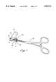
- FIG. 1is a perspective view illustrating a clip of the present invention, operable by a clip applier to occlude a body conduit;
- FIG. 2is an expanded view of the clip illustrated in FIG. 1;
- FIG. 3is a radial cross-section view of the clip illustrated in FIG. 1;
- FIG. 4is a side-elevation view of the clip illustrated in FIG. 1;
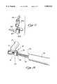
- FIG. 5is an expanded view of an additional embodiment of the clip of the present invention.
- FIG. 6is a radial cross-section view of the clip illustrated in FIG. 5;
- FIG. 7is a side-elevation view of the clip illustrated in FIG. 5;
- FIG. 8is an expanded view of a further embodiment of the clip of the present invention.
- FIG. 9is a radial cross-section view of the clip illustrated in FIG. 8;
- FIG. 10is a side-elevation view of the clip illustrated in FIG. 8;
- FIG. 11 to FIG. 15are assembly views of the clip illustrated in FIG. 8;
- FIG. 11is a perspective view illustrating the clip as two separated sub-assemblies, each including a barrel portion;
- FIG. 12is a perspective view illustrating the clip in an initial step of assembly
- FIG. 13is a perspective view illustrating the sub-assemblies rotated relative to each other to an interference fit
- FIG. 14is a perspective view illustrating one of the barrel portions bent to overcome the interference fit
- FIG. 15is a perspective view illustrating the barrel portions axially telescoped to their final orientation
- FIG. 16is an exploded view of a further embodiment of the clip of the present invention.
- FIG. 17is a radial cross-section view of the clip illustrated in FIG. 16;
- FIG. 18is a side-elevation view of the clip illustrated in FIG. 16.
- FIG. 19is a perspective view of one embodiment of the clip of the present invention illustrating insertion of the low-profile clip through the working channel of a trocar.
- a low-profile surgical clipis illustrated in the perspective view of FIG. 1 and designated generally by the reference numeral 10.
- the clip 10is illustrated in an operative position where it is disposed to occlude a body conduit such as a blood vessel 12.
- the clip 10includes a pair of opposing generally parallel jaws 14 and 16 which are movable between an open state and the illustrated closed state by operation of a clip applier 18.
- Each of the jaws 14 and 16can be provided with an insert 15, 17, respectively, which reduces trauma and increases traction with the vessel 12.
- the jaws 14, 16 of the clip 10are biased to the closed state by a spring 21 which is housed in a barrel 23.
- the spring 21has a compact or compressed configuration in a relaxed state and an expanded, elongated configuration in an axially tensioned state.
- the barrel 23is formed from a pair of telescoping barrel portions 25 and 27.
- the barrel portion 25is integral with the jaw 14 and the barrel portion 27 is integral with the jaw 16.
- Both of the barrel portions 25 and 27have a generally hollow, cylindrical configuration which extends along an axis 30 of the barrel 23.
- the barrel portion 27is sufficiently large to receive the barrel portion 25 in a telescoping relationship; the barrel portion 25 is sufficiently large to receive the spring 21.
- Engagement tabs 32 and 34are provided in a fixed relationship with each of the barrel portions 25 and 27, respectively.
- the engagement tab 32 associated with the barrel portion 25is provided with a groove or slot 36 which forms a rail 38 and a flange 41.
- a pair of axial slots 43 and 45are formed in the cylindrical wall of the barrel portion 27.
- the slot 45is sized and configured to receive the rail 38 of the tab 32, and the slot 43 is configured to receive the jaw 16 as the barrel portion 25 moves along the axis 30 in a telescoping relationship with the barrel portion 27.
- the telescoping movement of the barrel portions 25 and 27results in movement of the jaws 14 and 16 and the tabs 32 and 34 between proximate and spaced positions.
- the clip 10is in an open state best illustrated in the side-view of FIG. 4.
- the clip 10is in a closed state best illustrated in the cross-sectional view of FIG. 3.
- This embodimentalso includes end caps 44 and 46, each having an associated spring engagement flange 47, 50 as best illustrated in FIG. 2.
- the clip 10 in this embodimentis assembled by initially inserting the smaller barrel portion 25 into the larger barrel portion 27. During this step, the jaws 14, 16 are aligned and the rail 38 is positioned within the slot 45. One end of the tension spring 21 can be attached to the flange 50 of the end cap 41 and the spring 21 inserted into the smaller barrel portion 25. The tension spring 21 can then be axially expanded to permit attachment of the opposite end of the spring 21 to the flange 47 of the end cap 44. The end caps 44 and 46 can then be appropriately glued or otherwise fixed to the associated barrel portions 25 and 27.
- the tension spring 21biases the associated end caps 44, 46, the associated barrel portions 25, 27, and the associated jaws 14, 16 to their proximate positions. As noted, these proximate positions are associated with the closed state of the clip 10 as illustrated in FIG. 3.
- the clip 10is movable to the open state by inserting jaws of the clip applier 18 between the engagement tabs 32, 34, and operating the applier 18 to separate those tabs 32, 34. This opposes the bias on the spring 21, separates the end caps 43, 45 and the jaws 14, 16, and moves the clip 10 to the open state as illustrated in FIG. 4.
- the clip 10always has a height which is generally dictated by the height of the jaws 14, 16.
- the clip 10In the closed state illustrated in FIG. 3, the clip 10 is biased to the closed state and has a very low profile.
- the clip 10In the open state illustrated in FIG. 4, the clip 10, of course, has a higher profile, but this profile is generally not greater than the height of the jaws 14, 16.
- FIGS. 5-7An additional embodiment of the invention is illustrated in FIGS. 5-7.
- the clip 10aincludes the jaw 14a and insert 15a which are associated with the barrel portion 25a and end cap 43a. It also includes the jaw 16a and insert 17a which are associated with the barrel portion 27a and end cap 45a.
- this embodimentincludes the tension spring 21a, as well as the axial slots 43a and 45a in the barrel portion 27a.
- the slot 45aextends along a substantial length of the barrel portion 27a, but terminates at a surface 58 at the bottom of the slot 45a.
- FIG. 5also differs from that previously discussed primarily in the provision of a pair of finger tabs 61 and 63, which are associated with the barrel portions 25a and 27a, respectively.
- the finger tab 61is provided with an axial stop 64 and coupled to the barrel portion 25a by a connector 65.
- This connector 65includes a slot 67 which is defined by a rail 70 and flange 72.
- the rail 70extends axially terminating in a bottom surface 74. It also extends radially so that the flange 72 is spaced from the outer surface of the barrel portion 25a.
- Assembly of the clip 10acan be accomplished by initially inserting the barrel portion 25a into the barrel portion 27a. During this step, the rail 70 is positioned within the slot 45a and the surface 74 of the rail 70 approaches the surface 58 defining the slot 45a. With the rail 70 located within the slot 45a, the finger tab 63 can be glued or otherwise fixed to the barrel portion 27a, for example, at the position indicated by dotted lines 76. The spring 21a can then be mounted within the telescoping barrel portions 25a, 27a, and the end caps 44a and 46a glued into place in the manner previously discussed. With particular reference to FIGS. 6 and 7, it will be noted that in the clip 10a of this embodiment, the upper jaw 14a is associated with the lower finger tab 61 and the lower jaw 16a is associated with the upper finger tab 63.
- the spring 21abiases the clip 10a to the closed state illustrated in FIG. 6.
- This bias of the spring 21amust be opposed to move the clip 10a to the open state illustrated in FIG. 7.
- movement of the jaws 14a and 16a to the open stateis accomplished by moving the finger tabs 61 and 63 into close proximity as illustrated in FIG. 7.
- forcecan be exerted on the outer surfaces of the tabs 61 and 63 in order to open the jaws 14a and 16a. Since a squeezing force is much more natural between the thumb and fingers of the human hand, this clip 10a is particularly adapted for manipulation by the fingers of the user.
- the tabs 61 and 63are squeezed together to open the jaws 14a, 16a, and released to permit the bias of the spring 21a to close the jaws 14a, 16a and occlude the vessel 12 (FIG. 1).
- FIGS. 8-15structural elements which are similar to those previously discussed will be designated by the same reference numerals followed by the lower-case letter "b".
- the upper jaw 14bis associated with the barrel portion 25b, tab 61b, stop 64b, and connector 65b.
- the rail 70b and flange 72bwhich define the slot 67b.
- the lower jaw 16bis associated with the barrel portion 27b which is formed with the slots 43b and 45b.
- the rail 70b and flange 72bextend along a substantial length, more than half, of the barrel portion 25b.
- the finger tab 63b associated with the lower jaw 16bdiffers from that previously discussed in that it is fixed to or molded integral with the bottom barrel portion 27b prior to assembly.
- the finger tab 63bis not disposed over the slot 45b, but rather is configured with a notch 81 which is defined in part by a surface 83 that faces the slot 45b.
- the rail 70bis associated with the bottom surface 74b, while the flange 72b is associated with an outer surface 76.
- FIG. 8is of particular interest since it provides for operation of the clip 10b using a squeezing motion, but avoids the step of gluing, or otherwise attaching, the finger tab 63 during assembly of the clip.
- FIGS. 11-15Various steps in the process for assembling the clip 10b are illustrated in FIGS. 11-15.
- the jaws 14b, 16b, and barrel portions 25b, 27bare illustrated in a spaced relationship.
- an upper surface 85 associated with the lower barrel portion 27bis of particular interest.
- the barrel portion 25bis inserted into the barrel portion 27b and the surface 74b (FIG. 8) associated the rail 70b is brought into contact with the surface 85.
- the jaws 14b and 16bare angularly spaced a significant distance as illustrated in FIG. 12. Rotating the jaw 14b into closer proximity to the jaw 16b, as illustrated in FIG. 13, will bring the stop 64b into an interference fit with the finger tab 63b. This interference prohibits the parallel orientation of the jaws 14b, 16b because the rail 70b is not seated in the slot 45b.
- This interference fitis illustrated in FIG. 13 where it can be seen that the lateral surface of the rail 70b extends along a dotted line 87, rather than along the slot 45b.
- the slot 45bis expanded by forcing, moving, or bending the wall of the barrel portion 27b outwardly as shown by an arrow 90 in FIG. 14.
- the slot 45bexpands as it approaches the line 87 associated with the rail 70b.
- this line 87extends into the slot 45b, the barrel portion 25b is no longer inhibited from movement in the axial direction.
- the barrel portion 25bcan be moved axially along an arrow 92 as the rail 70b moves along the slot 45b. It will be noted that the angular interference fit between the stop 64b and the finger tab 63b does not inhibit this axial movement of the barrel portion 25b along the arrow 92.
- the stop 64bAs the rail 70b moves into the slot 45b, the stop 64b also moves axially with respect to the tab 63b. Eventually, this stop 64b clears the tab 63b and the inherent force of the bent wall forces the rail 70b and finger tab 65b into its final operative position primarily characterized by a parallel orientation of the jaws 14b and 16b. In this final orientation, illustrated in FIG. 15, the stop 64b associated with the finger tab 65b is disposed axially, beneath the finger tab 63b, and the rail 70b is free to slide axially a limited distance within the slot 45b. This sliding distance is limited by the interference fit which naturally occurs when the finger tab 63b comes into contact with the upper surface of the stop 64b.
- the clip 10bOperation of the clip 10b is similar to that of the clip 10a as can be seen from a comparison of FIGS. 9, 10 and FIGS. 6, 7, respectively.
- the clip 10is initially moved to an open state by squeezing the finger tabs 61 and 63 into proximity. This can be accomplished either with the fingers of the user or with the clip applier 18.
- the tab 61, 63can be released thereby permitting the tension spring 21 to bias the jaws 14, 16 to the closed state illustrated in FIG. 9.
- the height of the clip 10is dictated generally by the particular height of the jaws 14, 16. Although the height of the barrel portions 25, 27 generally follows this particular height, the height of the tabs 61, 63 is generally never greater than this particular height.
- FIGS. 16-18A ratchet embodiment of the invention is illustrated in FIGS. 16-18, where elements similar to those previously discussed are designated by the same reference numeral followed by the lower-case letter "c".
- FIG. 16illustrates the clip 10c to include the jaws 14c, 16c, as well as the tabs 61c and 63c.
- This embodimentdiffers from those previously discussed in that the barrel 23c has a generally rectangular configuration providing the clip 10c with a narrow, as well as a low-profile, configuration.
- the barrel 23chas barrel portions 25c and 27c which differ in several respects from those previously discussed.
- the barrel portion 27cis provided with a detent 94 which extends into an interior channel 96 of the barrel portion 27c.
- the barrel portion 25chas a generally U-shaped configuration with a pair of legs 98, 101 joined by a cross-member 103.
- the leg 98is coupled to the jaw 14c while the leg 101 is coupled to the tab 61c.
- the cross-member 103is disposed at one end of the legs 98 and 101 so that the leg 101 is free to bend slightly toward the leg 98.
- the surface of the leg 101 which faces proximally, in the direction of the tab 61cis provided with a series of teeth 105 which define a plurality of slots 107.
- the clip 10cis easily assembled by inserting the tab 61c into the channel 96 of the barrel portion 27c. Pivoting the jaw 14c counterclockwise in FIG. 16 enables the barrel portion 25c to be moved further into the channel 96.
- the clip 10cis movable between a closed state and an open state, as illustrated in FIGS. 17 and 18, respectively.
- the closed state illustrated in FIG. 17the jaws 14c and 16c are proximate and the tabs 61c and 63c are maximally separated.
- the jaws 14c, 16care maximally separated, and the tabs 61c and 63c and minimally separated.
- the teeth 105 and the detent 94form a ratchet or detent mechanism 110 which provides a predetermined degree of resistance at various positions between the extremes.
- both of the extreme states illustrated in FIGS. 17 and 18can be achieved with a squeezing motion.
- a squeezing motionIn order to open the jaws 14c, 16c from the closed state illustrated in FIG. 17, one merely engages the tabs 61c, 63c and squeezes them into proximity, as illustrated in FIG. 11.
- the maximum height of the clips 10cis generally defined by the maximum height of the jaws 14c and 16c. This height is dictated by the outer surfaces of the jaws 14c and 16c, which may be tapered outwardly to the maximum height in proximity to the barrel 25c. Generally speaking, although the barrel 25 and the caps 44 and 46 in several embodiments (such as FIG. 8) may increase this maximum height slightly, it can still be appreciated that in general the height of the clip 10 is dictated by the height of the jaws 14, 16.
- FIG. 19wherein the clip 10 is adapted for insertion through a tube 94 having a working channel 96.
- the tube 94may be an endoscope, a trocar, or any other access device extending across a body wall.
- the barrel 25does not provide any substantial increase in height.
- the clip 10has jaws that are approximately 3/4" in length and the height of the clip in the closed state is about 3/8".
- An additional advantage associated with the present clip constructionis its ability to maintain jaw symmetry and linear orientation about the axis of the clip applier. This is of particular advantage when used through a trocar or used to access a remote site.
- the spring 21is formed of stainless steel wire having a diameter of about 0.018".
- the springis wound to a diameter of about 0.200" and a length of about 0.33" to provide a spring constant of about 1 pound per inch.
- the inserts 15 and 17can also vary widely in different embodiments of the invention.
- the inserts 15, 17have a foam rubber substrate, but are covered with a mesh structure which facilitates traction with the vessel 12.
Landscapes
- Health & Medical Sciences (AREA)
- Surgery (AREA)
- Life Sciences & Earth Sciences (AREA)
- Heart & Thoracic Surgery (AREA)
- Nuclear Medicine, Radiotherapy & Molecular Imaging (AREA)
- Vascular Medicine (AREA)
- Engineering & Computer Science (AREA)
- Biomedical Technology (AREA)
- Reproductive Health (AREA)
- Medical Informatics (AREA)
- Molecular Biology (AREA)
- Animal Behavior & Ethology (AREA)
- General Health & Medical Sciences (AREA)
- Public Health (AREA)
- Veterinary Medicine (AREA)
- Surgical Instruments (AREA)
Abstract
Description
Claims (21)
Priority Applications (3)
| Application Number | Priority Date | Filing Date | Title |
|---|---|---|---|
| US08/949,126US5984934A (en) | 1997-10-10 | 1997-10-10 | Low-profile surgical clip |
| JP2000515500AJP4233752B2 (en) | 1997-10-10 | 1998-10-06 | Low profile surgical clip |
| PCT/US1998/021127WO1999018858A1 (en) | 1997-10-10 | 1998-10-06 | Low-profile surgical clip |
Applications Claiming Priority (1)
| Application Number | Priority Date | Filing Date | Title |
|---|---|---|---|
| US08/949,126US5984934A (en) | 1997-10-10 | 1997-10-10 | Low-profile surgical clip |
Publications (1)
| Publication Number | Publication Date |
|---|---|
| US5984934Atrue US5984934A (en) | 1999-11-16 |
Family
ID=25488630
Family Applications (1)
| Application Number | Title | Priority Date | Filing Date |
|---|---|---|---|
| US08/949,126Expired - LifetimeUS5984934A (en) | 1997-10-10 | 1997-10-10 | Low-profile surgical clip |
Country Status (3)
| Country | Link |
|---|---|
| US (1) | US5984934A (en) |
| JP (1) | JP4233752B2 (en) |
| WO (1) | WO1999018858A1 (en) |
Cited By (85)
| Publication number | Priority date | Publication date | Assignee | Title |
|---|---|---|---|---|
| WO2001005308A1 (en)* | 1999-07-15 | 2001-01-25 | Applied Medical Resources Corporation | Low-profile surgical clip |
| WO2001058367A1 (en) | 2000-02-11 | 2001-08-16 | Novare Surgical Systems, Inc. | Occlusion device |
| US6277140B2 (en) | 2000-01-05 | 2001-08-21 | Integrated Vascular Systems, Inc. | Vascular sheath with puncture site closure apparatus and methods of use |
| US6391048B1 (en) | 2000-01-05 | 2002-05-21 | Integrated Vascular Systems, Inc. | Integrated vascular device with puncture site closure component and sealant and methods of use |
| US6461364B1 (en) | 2000-01-05 | 2002-10-08 | Integrated Vascular Systems, Inc. | Vascular sheath with bioabsorbable puncture site closure apparatus and methods of use |
| US20020193808A1 (en)* | 2000-01-05 | 2002-12-19 | Belef W. Martin | Apparatus and methods for delivering a closure device |
| US20030176879A1 (en)* | 2002-03-12 | 2003-09-18 | Anderson Russell J. | Surgical clip with adjustable biasing force |
| US20030212435A1 (en)* | 2002-03-26 | 2003-11-13 | Adam Gold | Handleless clamping device |
| US6695867B2 (en) | 2002-02-21 | 2004-02-24 | Integrated Vascular Systems, Inc. | Plunger apparatus and methods for delivering a closure device |
| US6719777B2 (en) | 2000-12-07 | 2004-04-13 | Integrated Vascular Systems, Inc. | Closure device and methods for making and using them |
| WO2004023976A3 (en)* | 2002-09-13 | 2004-05-21 | Damage Control Surgical Techno | Method and apparatus for vascular and visceral clipping |
| US6780197B2 (en) | 2000-01-05 | 2004-08-24 | Integrated Vascular Systems, Inc. | Apparatus and methods for delivering a vascular closure device to a body lumen |
| US20040254596A1 (en)* | 2003-06-16 | 2004-12-16 | Synovis Life Technologies, Inc. | Vascular clamp |
| US20050222590A1 (en)* | 2004-04-02 | 2005-10-06 | Gadberry Donald L | Suture clip with stop ribs and method for making same |
| US20060161182A1 (en)* | 2005-01-19 | 2006-07-20 | Applied Medical Resources Corporation | Single fire vascular clip applier with disposable jaw |
| US20070106314A1 (en)* | 2005-11-02 | 2007-05-10 | University Of Massachusetts | Tissue clamp |
| US20070191883A1 (en)* | 2006-02-16 | 2007-08-16 | Peter Lazic | Applying forceps for a clip |
| US20080004637A1 (en)* | 2006-04-29 | 2008-01-03 | Klassen James B | Surgical clip, applicator and applicator methods |
| US20080249547A1 (en)* | 2005-11-02 | 2008-10-09 | University Of Massachusetts | Tissue clamp |
| USD611144S1 (en) | 2006-06-28 | 2010-03-02 | Abbott Laboratories | Apparatus for delivering a closure element |
| US20100187392A1 (en)* | 2007-04-24 | 2010-07-29 | Endress + Hauser Flowtec Ag | Apparatus for securing a measuring or display unit on an object |
| US7806904B2 (en) | 2000-12-07 | 2010-10-05 | Integrated Vascular Systems, Inc. | Closure device |
| US7806910B2 (en) | 2002-11-26 | 2010-10-05 | Abbott Laboratories | Multi-element biased suture clip |
| US7841502B2 (en) | 2007-12-18 | 2010-11-30 | Abbott Laboratories | Modular clip applier |
| US7842068B2 (en) | 2000-12-07 | 2010-11-30 | Integrated Vascular Systems, Inc. | Apparatus and methods for providing tactile feedback while delivering a closure device |
| US7850709B2 (en) | 2002-06-04 | 2010-12-14 | Abbott Vascular Inc. | Blood vessel closure clip and delivery device |
| US7850797B2 (en) | 2002-12-31 | 2010-12-14 | Integrated Vascular Systems, Inc. | Methods for manufacturing a clip and clip |
| US7857828B2 (en) | 2003-01-30 | 2010-12-28 | Integrated Vascular Systems, Inc. | Clip applier and methods of use |
| US7867249B2 (en) | 2003-01-30 | 2011-01-11 | Integrated Vascular Systems, Inc. | Clip applier and methods of use |
| US7879071B2 (en) | 2000-12-07 | 2011-02-01 | Integrated Vascular Systems, Inc. | Closure device and methods for making and using them |
| US7887563B2 (en) | 2001-06-07 | 2011-02-15 | Abbott Vascular Inc. | Surgical staple |
| US20110046437A1 (en)* | 2009-08-24 | 2011-02-24 | Cvdevices, Llc | Tissue restoration devices, systems, and methods |
| US20110046641A1 (en)* | 2009-08-24 | 2011-02-24 | Cvdevices, Llc | Devices, systems and methods for tissue restoration |
| US20110224700A1 (en)* | 2010-03-09 | 2011-09-15 | Teleflex Medical Incorporated | Narrow Profile Surgical Ligation Clip |
| US8048108B2 (en) | 2005-08-24 | 2011-11-01 | Abbott Vascular Inc. | Vascular closure methods and apparatuses |
| US8202293B2 (en) | 2003-01-30 | 2012-06-19 | Integrated Vascular Systems, Inc. | Clip applier and methods of use |
| US8226681B2 (en) | 2007-06-25 | 2012-07-24 | Abbott Laboratories | Methods, devices, and apparatus for managing access through tissue |
| US8303624B2 (en) | 2010-03-15 | 2012-11-06 | Abbott Cardiovascular Systems, Inc. | Bioabsorbable plug |
| US8313497B2 (en) | 2005-07-01 | 2012-11-20 | Abbott Laboratories | Clip applier and methods of use |
| US8323312B2 (en) | 2008-12-22 | 2012-12-04 | Abbott Laboratories | Closure device |
| US8398656B2 (en) | 2003-01-30 | 2013-03-19 | Integrated Vascular Systems, Inc. | Clip applier and methods of use |
| US8398676B2 (en) | 2008-10-30 | 2013-03-19 | Abbott Vascular Inc. | Closure device |
| US8556930B2 (en) | 2006-06-28 | 2013-10-15 | Abbott Laboratories | Vessel closure device |
| US8556932B2 (en) | 2011-05-19 | 2013-10-15 | Abbott Cardiovascular Systems, Inc. | Collapsible plug for tissue closure |
| US8590760B2 (en) | 2004-05-25 | 2013-11-26 | Abbott Vascular Inc. | Surgical stapler |
| US8603116B2 (en) | 2010-08-04 | 2013-12-10 | Abbott Cardiovascular Systems, Inc. | Closure device with long tines |
| US8617184B2 (en) | 2011-02-15 | 2013-12-31 | Abbott Cardiovascular Systems, Inc. | Vessel closure system |
| US8672953B2 (en) | 2007-12-17 | 2014-03-18 | Abbott Laboratories | Tissue closure system and methods of use |
| US8690910B2 (en) | 2000-12-07 | 2014-04-08 | Integrated Vascular Systems, Inc. | Closure device and methods for making and using them |
| US8758400B2 (en) | 2000-01-05 | 2014-06-24 | Integrated Vascular Systems, Inc. | Closure system and methods of use |
| US8758399B2 (en) | 2010-08-02 | 2014-06-24 | Abbott Cardiovascular Systems, Inc. | Expandable bioabsorbable plug apparatus and method |
| US8758398B2 (en) | 2006-09-08 | 2014-06-24 | Integrated Vascular Systems, Inc. | Apparatus and method for delivering a closure element |
| US8784447B2 (en) | 2000-09-08 | 2014-07-22 | Abbott Vascular Inc. | Surgical stapler |
| US8808310B2 (en) | 2006-04-20 | 2014-08-19 | Integrated Vascular Systems, Inc. | Resettable clip applier and reset tools |
| US8821534B2 (en) | 2010-12-06 | 2014-09-02 | Integrated Vascular Systems, Inc. | Clip applier having improved hemostasis and methods of use |
| US8858594B2 (en) | 2008-12-22 | 2014-10-14 | Abbott Laboratories | Curved closure device |
| US8876859B2 (en) | 2010-12-14 | 2014-11-04 | Patricia Buehler | Devices for performing blepharoplasty and methods of using the same |
| US8893947B2 (en) | 2007-12-17 | 2014-11-25 | Abbott Laboratories | Clip applier and methods of use |
| US8905937B2 (en) | 2009-02-26 | 2014-12-09 | Integrated Vascular Systems, Inc. | Methods and apparatus for locating a surface of a body lumen |
| US8920442B2 (en) | 2005-08-24 | 2014-12-30 | Abbott Vascular Inc. | Vascular opening edge eversion methods and apparatuses |
| US8926633B2 (en) | 2005-06-24 | 2015-01-06 | Abbott Laboratories | Apparatus and method for delivering a closure element |
| US9089674B2 (en) | 2000-10-06 | 2015-07-28 | Integrated Vascular Systems, Inc. | Apparatus and methods for positioning a vascular sheath |
| US9089311B2 (en) | 2009-01-09 | 2015-07-28 | Abbott Vascular Inc. | Vessel closure devices and methods |
| US9149276B2 (en) | 2011-03-21 | 2015-10-06 | Abbott Cardiovascular Systems, Inc. | Clip and deployment apparatus for tissue closure |
| US9173644B2 (en) | 2009-01-09 | 2015-11-03 | Abbott Vascular Inc. | Closure devices, systems, and methods |
| US9259562B2 (en)* | 2012-07-10 | 2016-02-16 | Lifeline Scientific, Inc. | Cannula |
| US9282965B2 (en)* | 2008-05-16 | 2016-03-15 | Abbott Laboratories | Apparatus and methods for engaging tissue |
| US9314230B2 (en) | 2009-01-09 | 2016-04-19 | Abbott Vascular Inc. | Closure device with rapidly eroding anchor |
| US9332976B2 (en) | 2011-11-30 | 2016-05-10 | Abbott Cardiovascular Systems, Inc. | Tissue closure device |
| US9364209B2 (en) | 2012-12-21 | 2016-06-14 | Abbott Cardiovascular Systems, Inc. | Articulating suturing device |
| US9414824B2 (en) | 2009-01-16 | 2016-08-16 | Abbott Vascular Inc. | Closure devices, systems, and methods |
| US9414820B2 (en) | 2009-01-09 | 2016-08-16 | Abbott Vascular Inc. | Closure devices, systems, and methods |
| US9456811B2 (en) | 2005-08-24 | 2016-10-04 | Abbott Vascular Inc. | Vascular closure methods and apparatuses |
| US9486191B2 (en) | 2009-01-09 | 2016-11-08 | Abbott Vascular, Inc. | Closure devices |
| US9579091B2 (en) | 2000-01-05 | 2017-02-28 | Integrated Vascular Systems, Inc. | Closure system and methods of use |
| US9585647B2 (en) | 2009-08-26 | 2017-03-07 | Abbott Laboratories | Medical device for repairing a fistula |
| US20180042613A1 (en)* | 2015-03-03 | 2018-02-15 | Vascular Devices Pty. Ltd. | Surgical clamping devices |
| US9980841B2 (en) | 2009-08-24 | 2018-05-29 | Cvdevices, Llc | Devices and systems configured to fit around a tissue using the same |
| US10136898B2 (en) | 2010-03-09 | 2018-11-27 | Teleflex Medical Incorporated | Narrow profile surgical ligation clip |
| US10307166B2 (en) | 2011-09-15 | 2019-06-04 | Teleflex Medical Incorporated | Manual surgical ligation clip applier |
| WO2020003214A1 (en)* | 2018-06-29 | 2020-01-02 | Viretec Gestion Y Desarrollo, S.A. De C.V. | Device for blood vessel occlusion and haemorrhage control and method for placement and removal thereof |
| EP3654850A4 (en)* | 2017-07-18 | 2021-04-21 | Vascular Devices Pty Ltd | SURGICAL CLAMP |
| WO2024229226A1 (en)* | 2023-05-03 | 2024-11-07 | Edwards Lifesciences Corporation | Clips with couplers for left atrial appendage closure |
| WO2024229210A1 (en)* | 2023-05-03 | 2024-11-07 | Edwards Lifesciences Corporation | Systems, apparatuses, and methods for clips for left atrial appendage closure |
| US12376852B2 (en) | 2022-04-29 | 2025-08-05 | Osheru, Inc. | Wound creation for excess skin removal and closure systems and methods |
Families Citing this family (6)
| Publication number | Priority date | Publication date | Assignee | Title |
|---|---|---|---|---|
| GB0302098D0 (en)* | 2003-01-29 | 2003-02-26 | Univ London | Improvements in and relating to surgical clips |
| EP2015681B1 (en) | 2006-05-03 | 2018-03-28 | Datascope Corp. | Tissue closure device |
| JP4981536B2 (en)* | 2007-06-21 | 2012-07-25 | Hoya株式会社 | Endoscopic clip device |
| WO2015077356A1 (en) | 2013-11-19 | 2015-05-28 | Wheeler William K | Fastener applicator with interlock |
| KR200480287Y1 (en)* | 2014-11-07 | 2016-05-04 | 김광현 | Nose pick for baby |
| JP7348199B2 (en) | 2018-03-28 | 2023-09-20 | データスコープ コーポレイション | Device for atrial appendage exclusion |
Citations (22)
| Publication number | Priority date | Publication date | Assignee | Title |
|---|---|---|---|---|
| US3182373A (en)* | 1963-09-03 | 1965-05-11 | Margaret C L Strand | Hose clamp |
| US3509882A (en)* | 1967-09-18 | 1970-05-05 | American Hospital Supply Corp | Parallel jaw spring clip and applicator |
| US3510923A (en)* | 1968-06-20 | 1970-05-12 | American Hospital Supply Corp | Parallel jaw ratchet clip and retractor |
| US3579751A (en)* | 1968-05-30 | 1971-05-25 | Lucien Julienne Arthur Jonckhe | Clips useful in the medical field |
| US4324248A (en)* | 1980-05-30 | 1982-04-13 | Metatech Corporation | Microsurgical clip |
| US4407285A (en)* | 1981-04-13 | 1983-10-04 | Metatech Corporation | Microsurgical clip for brain surgery or the like |
| GB2124502A (en)* | 1982-08-02 | 1984-02-22 | Ethicon Inc | Surgical clips |
| US4681109A (en)* | 1985-06-12 | 1987-07-21 | Juan Arroyo | Surgical instrumentation for blood vessels |
| US4796625A (en)* | 1982-11-15 | 1989-01-10 | Codman & Shurtleff, Inc. | Aneurysm clip |
| US4815466A (en)* | 1982-09-30 | 1989-03-28 | Perlin Alfred R | Surgical clip |
| US4817604A (en)* | 1987-09-11 | 1989-04-04 | Smith Iii Ray C | Disposable cholangiogram clip |
| US4832027A (en)* | 1985-05-31 | 1989-05-23 | Alice Utz | Surgical clamp |
| US4931058A (en)* | 1989-08-16 | 1990-06-05 | Applied Vascular Devices, Inc. | Parallel jaw spring clip and method of making same |
| FR2644056A1 (en)* | 1989-03-13 | 1990-09-14 | Fiandrino Alain | (Surgical) clamp forceps |
| US4971055A (en)* | 1987-07-14 | 1990-11-20 | Zeppelin Dieter Von | Blood vessel clamp |
| US4976721A (en)* | 1988-12-14 | 1990-12-11 | The Research Foundation Of State University Of New York | Surgical clamping device |
| EP0432743A1 (en)* | 1989-12-12 | 1991-06-19 | Hilmar Hubbes | Wound clip, particularly surgical microclip |
| US5042118A (en)* | 1988-03-25 | 1991-08-27 | Rubik Studio Muszaki Fejleszto Kisszovetkezet | Clamping device |
| US5074870A (en)* | 1989-10-06 | 1991-12-24 | Zeppelin Dieter Von | Clamp for clamping blood vessels or aneurysms |
| US5103839A (en)* | 1987-06-24 | 1992-04-14 | United States Surgical Corporation | Method of using a vascular clamp assembly |
| US5142776A (en)* | 1991-03-18 | 1992-09-01 | Kabelmetal Electro Gmbh | Method and apparatus for heat sealing of joints and connections |
| US5653720A (en)* | 1995-07-18 | 1997-08-05 | Applied Medical Resources | Surgical clip and method of assembly |
- 1997
- 1997-10-10USUS08/949,126patent/US5984934A/ennot_activeExpired - Lifetime
- 1998
- 1998-10-06JPJP2000515500Apatent/JP4233752B2/ennot_activeExpired - Fee Related
- 1998-10-06WOPCT/US1998/021127patent/WO1999018858A1/enactiveApplication Filing
Patent Citations (22)
| Publication number | Priority date | Publication date | Assignee | Title |
|---|---|---|---|---|
| US3182373A (en)* | 1963-09-03 | 1965-05-11 | Margaret C L Strand | Hose clamp |
| US3509882A (en)* | 1967-09-18 | 1970-05-05 | American Hospital Supply Corp | Parallel jaw spring clip and applicator |
| US3579751A (en)* | 1968-05-30 | 1971-05-25 | Lucien Julienne Arthur Jonckhe | Clips useful in the medical field |
| US3510923A (en)* | 1968-06-20 | 1970-05-12 | American Hospital Supply Corp | Parallel jaw ratchet clip and retractor |
| US4324248A (en)* | 1980-05-30 | 1982-04-13 | Metatech Corporation | Microsurgical clip |
| US4407285A (en)* | 1981-04-13 | 1983-10-04 | Metatech Corporation | Microsurgical clip for brain surgery or the like |
| GB2124502A (en)* | 1982-08-02 | 1984-02-22 | Ethicon Inc | Surgical clips |
| US4815466A (en)* | 1982-09-30 | 1989-03-28 | Perlin Alfred R | Surgical clip |
| US4796625A (en)* | 1982-11-15 | 1989-01-10 | Codman & Shurtleff, Inc. | Aneurysm clip |
| US4832027A (en)* | 1985-05-31 | 1989-05-23 | Alice Utz | Surgical clamp |
| US4681109A (en)* | 1985-06-12 | 1987-07-21 | Juan Arroyo | Surgical instrumentation for blood vessels |
| US5103839A (en)* | 1987-06-24 | 1992-04-14 | United States Surgical Corporation | Method of using a vascular clamp assembly |
| US4971055A (en)* | 1987-07-14 | 1990-11-20 | Zeppelin Dieter Von | Blood vessel clamp |
| US4817604A (en)* | 1987-09-11 | 1989-04-04 | Smith Iii Ray C | Disposable cholangiogram clip |
| US5042118A (en)* | 1988-03-25 | 1991-08-27 | Rubik Studio Muszaki Fejleszto Kisszovetkezet | Clamping device |
| US4976721A (en)* | 1988-12-14 | 1990-12-11 | The Research Foundation Of State University Of New York | Surgical clamping device |
| FR2644056A1 (en)* | 1989-03-13 | 1990-09-14 | Fiandrino Alain | (Surgical) clamp forceps |
| US4931058A (en)* | 1989-08-16 | 1990-06-05 | Applied Vascular Devices, Inc. | Parallel jaw spring clip and method of making same |
| US5074870A (en)* | 1989-10-06 | 1991-12-24 | Zeppelin Dieter Von | Clamp for clamping blood vessels or aneurysms |
| EP0432743A1 (en)* | 1989-12-12 | 1991-06-19 | Hilmar Hubbes | Wound clip, particularly surgical microclip |
| US5142776A (en)* | 1991-03-18 | 1992-09-01 | Kabelmetal Electro Gmbh | Method and apparatus for heat sealing of joints and connections |
| US5653720A (en)* | 1995-07-18 | 1997-08-05 | Applied Medical Resources | Surgical clip and method of assembly |
Cited By (176)
| Publication number | Priority date | Publication date | Assignee | Title |
|---|---|---|---|---|
| WO2001005308A1 (en)* | 1999-07-15 | 2001-01-25 | Applied Medical Resources Corporation | Low-profile surgical clip |
| US6267773B1 (en)* | 1999-07-15 | 2001-07-31 | Donald L. Gadberry | Low profile surgical clip |
| US8758396B2 (en) | 2000-01-05 | 2014-06-24 | Integrated Vascular Systems, Inc. | Vascular sheath with bioabsorbable puncture site closure apparatus and methods of use |
| US6942674B2 (en) | 2000-01-05 | 2005-09-13 | Integrated Vascular Systems, Inc. | Apparatus and methods for delivering a closure device |
| US6391048B1 (en) | 2000-01-05 | 2002-05-21 | Integrated Vascular Systems, Inc. | Integrated vascular device with puncture site closure component and sealant and methods of use |
| US6461364B1 (en) | 2000-01-05 | 2002-10-08 | Integrated Vascular Systems, Inc. | Vascular sheath with bioabsorbable puncture site closure apparatus and methods of use |
| US20020193808A1 (en)* | 2000-01-05 | 2002-12-19 | Belef W. Martin | Apparatus and methods for delivering a closure device |
| US10111664B2 (en) | 2000-01-05 | 2018-10-30 | Integrated Vascular Systems, Inc. | Closure system and methods of use |
| US6632238B2 (en) | 2000-01-05 | 2003-10-14 | Integrated Vascular Systems, Inc. | Vascular sheath with puncture site closure apparatus and methods of use |
| US7931669B2 (en) | 2000-01-05 | 2011-04-26 | Integrated Vascular Systems, Inc. | Integrated vascular device with puncture site closure component and sealant and methods of use |
| US7901428B2 (en) | 2000-01-05 | 2011-03-08 | Integrated Vascular Systems, Inc. | Vascular sheath with bioabsorbable puncture site closure apparatus and methods of use |
| US6780197B2 (en) | 2000-01-05 | 2004-08-24 | Integrated Vascular Systems, Inc. | Apparatus and methods for delivering a vascular closure device to a body lumen |
| US6277140B2 (en) | 2000-01-05 | 2001-08-21 | Integrated Vascular Systems, Inc. | Vascular sheath with puncture site closure apparatus and methods of use |
| US7819895B2 (en) | 2000-01-05 | 2010-10-26 | Integrated Vascular Systems, Inc. | Vascular sheath with bioabsorbable puncture site closure apparatus and methods of use |
| US8758400B2 (en) | 2000-01-05 | 2014-06-24 | Integrated Vascular Systems, Inc. | Closure system and methods of use |
| US8956388B2 (en) | 2000-01-05 | 2015-02-17 | Integrated Vascular Systems, Inc. | Integrated vascular device with puncture site closure component and sealant |
| US9050087B2 (en) | 2000-01-05 | 2015-06-09 | Integrated Vascular Systems, Inc. | Integrated vascular device with puncture site closure component and sealant and methods of use |
| US7828817B2 (en) | 2000-01-05 | 2010-11-09 | Integrated Vascular Systems, Inc. | Apparatus and methods for delivering a closure device |
| US9579091B2 (en) | 2000-01-05 | 2017-02-28 | Integrated Vascular Systems, Inc. | Closure system and methods of use |
| WO2001058367A1 (en) | 2000-02-11 | 2001-08-16 | Novare Surgical Systems, Inc. | Occlusion device |
| US9060769B2 (en) | 2000-09-08 | 2015-06-23 | Abbott Vascular Inc. | Surgical stapler |
| US8784447B2 (en) | 2000-09-08 | 2014-07-22 | Abbott Vascular Inc. | Surgical stapler |
| US9402625B2 (en) | 2000-09-08 | 2016-08-02 | Abbott Vascular Inc. | Surgical stapler |
| US9089674B2 (en) | 2000-10-06 | 2015-07-28 | Integrated Vascular Systems, Inc. | Apparatus and methods for positioning a vascular sheath |
| US10245013B2 (en) | 2000-12-07 | 2019-04-02 | Integrated Vascular Systems, Inc. | Closure device and methods for making and using them |
| US7879071B2 (en) | 2000-12-07 | 2011-02-01 | Integrated Vascular Systems, Inc. | Closure device and methods for making and using them |
| US8257390B2 (en) | 2000-12-07 | 2012-09-04 | Integrated Vascular Systems, Inc. | Closure device and methods for making and using them |
| US8236026B2 (en) | 2000-12-07 | 2012-08-07 | Integrated Vascular Systems, Inc. | Closure device and methods for making and using them |
| US8486092B2 (en) | 2000-12-07 | 2013-07-16 | Integrated Vascular Systems, Inc. | Closure device and methods for making and using them |
| US9554786B2 (en) | 2000-12-07 | 2017-01-31 | Integrated Vascular Systems, Inc. | Closure device and methods for making and using them |
| US8486108B2 (en) | 2000-12-07 | 2013-07-16 | Integrated Vascular Systems, Inc. | Closure device and methods for making and using them |
| US8182497B2 (en) | 2000-12-07 | 2012-05-22 | Integrated Vascular Systems, Inc. | Closure device |
| US8128644B2 (en) | 2000-12-07 | 2012-03-06 | Integrated Vascular Systems, Inc. | Closure device and methods for making and using them |
| US8597325B2 (en) | 2000-12-07 | 2013-12-03 | Integrated Vascular Systems, Inc. | Apparatus and methods for providing tactile feedback while delivering a closure device |
| US8603136B2 (en) | 2000-12-07 | 2013-12-10 | Integrated Vascular Systems, Inc. | Apparatus and methods for providing tactile feedback while delivering a closure device |
| US8690910B2 (en) | 2000-12-07 | 2014-04-08 | Integrated Vascular Systems, Inc. | Closure device and methods for making and using them |
| US9320522B2 (en) | 2000-12-07 | 2016-04-26 | Integrated Vascular Systems, Inc. | Closure device and methods for making and using them |
| US7806904B2 (en) | 2000-12-07 | 2010-10-05 | Integrated Vascular Systems, Inc. | Closure device |
| US6719777B2 (en) | 2000-12-07 | 2004-04-13 | Integrated Vascular Systems, Inc. | Closure device and methods for making and using them |
| US7887555B2 (en) | 2000-12-07 | 2011-02-15 | Integrated Vascular Systems, Inc. | Closure device and methods for making and using them |
| US9585646B2 (en) | 2000-12-07 | 2017-03-07 | Integrated Vascular Systems, Inc. | Closure device and methods for making and using them |
| US7842068B2 (en) | 2000-12-07 | 2010-11-30 | Integrated Vascular Systems, Inc. | Apparatus and methods for providing tactile feedback while delivering a closure device |
| US7887563B2 (en) | 2001-06-07 | 2011-02-15 | Abbott Vascular Inc. | Surgical staple |
| US7918873B2 (en) | 2001-06-07 | 2011-04-05 | Abbott Vascular Inc. | Surgical staple |
| US8728119B2 (en) | 2001-06-07 | 2014-05-20 | Abbott Vascular Inc. | Surgical staple |
| US8579932B2 (en) | 2002-02-21 | 2013-11-12 | Integrated Vascular Systems, Inc. | Sheath apparatus and methods for delivering a closure device |
| US6695867B2 (en) | 2002-02-21 | 2004-02-24 | Integrated Vascular Systems, Inc. | Plunger apparatus and methods for delivering a closure device |
| US6749621B2 (en) | 2002-02-21 | 2004-06-15 | Integrated Vascular Systems, Inc. | Sheath apparatus and methods for delivering a closure device |
| US10201340B2 (en) | 2002-02-21 | 2019-02-12 | Integrated Vascular Systems, Inc. | Sheath apparatus and methods for delivering a closure device |
| US9498196B2 (en) | 2002-02-21 | 2016-11-22 | Integrated Vascular Systems, Inc. | Sheath apparatus and methods for delivering a closure device |
| US6802848B2 (en) | 2002-03-12 | 2004-10-12 | Novare Surgical Systems, Inc. | Surgical clip with adjustable biasing force |
| US20030176879A1 (en)* | 2002-03-12 | 2003-09-18 | Anderson Russell J. | Surgical clip with adjustable biasing force |
| US20090093842A1 (en)* | 2002-03-26 | 2009-04-09 | Novare Surgical Systems, Inc. | Handleless clamping device |
| US20090093841A1 (en)* | 2002-03-26 | 2009-04-09 | Novare Surgical Systems, Inc. | Handleless clamping device |
| US11439394B2 (en) | 2002-03-26 | 2022-09-13 | Intuitive Surgical Operations, Inc. | Handleless clamping device |
| US20090093828A1 (en)* | 2002-03-26 | 2009-04-09 | Novare Surgical Systems, Inc. | Handleless clamping device |
| US8361108B2 (en) | 2002-03-26 | 2013-01-29 | Intuitive Surgical Operations, Inc. | Handleless clamping device |
| US9782174B2 (en) | 2002-03-26 | 2017-10-10 | Intuitive Surgical Operations, Inc. | Handleless clamping device |
| US20030212435A1 (en)* | 2002-03-26 | 2003-11-13 | Adam Gold | Handleless clamping device |
| US7588585B2 (en) | 2002-03-26 | 2009-09-15 | Novare Surgical Systems, Inc. | Handleless clamping device |
| US10702272B2 (en) | 2002-03-26 | 2020-07-07 | Intuitive Surgical Operations, Inc. | Handleless clamping device |
| US8506590B2 (en) | 2002-03-26 | 2013-08-13 | Intuitive Surgical Operations, Inc. | Handleless clamping device |
| US9980728B2 (en) | 2002-06-04 | 2018-05-29 | Abbott Vascular Inc | Blood vessel closure clip and delivery device |
| US8192459B2 (en) | 2002-06-04 | 2012-06-05 | Abbott Vascular Inc. | Blood vessel closure clip and delivery device |
| US7850709B2 (en) | 2002-06-04 | 2010-12-14 | Abbott Vascular Inc. | Blood vessel closure clip and delivery device |
| US9295469B2 (en) | 2002-06-04 | 2016-03-29 | Abbott Vascular Inc. | Blood vessel closure clip and delivery device |
| US8469995B2 (en) | 2002-06-04 | 2013-06-25 | Abbott Vascular Inc. | Blood vessel closure clip and delivery device |
| US8187290B2 (en) | 2002-09-13 | 2012-05-29 | Damage Control Surgical Technologies, Inc. | Method and apparatus for vascular and visceral clipping |
| WO2004023976A3 (en)* | 2002-09-13 | 2004-05-21 | Damage Control Surgical Techno | Method and apparatus for vascular and visceral clipping |
| US20050251183A1 (en)* | 2002-09-13 | 2005-11-10 | Damage Control Surgical Technologies, Inc. | Method and apparatus for vascular and visceral clipping |
| US20080132915A1 (en)* | 2002-09-13 | 2008-06-05 | Buckman Robert F | Method and apparatus for vascular and visceral clipping |
| US7322995B2 (en)* | 2002-09-13 | 2008-01-29 | Damage Control Surgical Technologies, Inc. | Method and apparatus for vascular and visceral clipping |
| US7806910B2 (en) | 2002-11-26 | 2010-10-05 | Abbott Laboratories | Multi-element biased suture clip |
| US8585836B2 (en) | 2002-12-31 | 2013-11-19 | Integrated Vascular Systems, Inc. | Methods for manufacturing a clip and clip |
| US7850797B2 (en) | 2002-12-31 | 2010-12-14 | Integrated Vascular Systems, Inc. | Methods for manufacturing a clip and clip |
| US7854810B2 (en) | 2002-12-31 | 2010-12-21 | Integrated Vascular Systems, Inc. | Methods for manufacturing a clip and clip |
| US8202283B2 (en) | 2002-12-31 | 2012-06-19 | Integrated Vascular Systems, Inc. | Methods for manufacturing a clip and clip |
| US8926656B2 (en) | 2003-01-30 | 2015-01-06 | Integated Vascular Systems, Inc. | Clip applier and methods of use |
| US10398418B2 (en) | 2003-01-30 | 2019-09-03 | Integrated Vascular Systems, Inc. | Clip applier and methods of use |
| US9271707B2 (en) | 2003-01-30 | 2016-03-01 | Integrated Vascular Systems, Inc. | Clip applier and methods of use |
| US7867249B2 (en) | 2003-01-30 | 2011-01-11 | Integrated Vascular Systems, Inc. | Clip applier and methods of use |
| US8202293B2 (en) | 2003-01-30 | 2012-06-19 | Integrated Vascular Systems, Inc. | Clip applier and methods of use |
| US8202294B2 (en) | 2003-01-30 | 2012-06-19 | Integrated Vascular Systems, Inc. | Clip applier and methods of use |
| US7905900B2 (en) | 2003-01-30 | 2011-03-15 | Integrated Vascular Systems, Inc. | Clip applier and methods of use |
| US8529587B2 (en) | 2003-01-30 | 2013-09-10 | Integrated Vascular Systems, Inc. | Methods of use of a clip applier |
| US7857828B2 (en) | 2003-01-30 | 2010-12-28 | Integrated Vascular Systems, Inc. | Clip applier and methods of use |
| US8398656B2 (en) | 2003-01-30 | 2013-03-19 | Integrated Vascular Systems, Inc. | Clip applier and methods of use |
| US11589856B2 (en) | 2003-01-30 | 2023-02-28 | Integrated Vascular Systems, Inc. | Clip applier and methods of use |
| US9398914B2 (en) | 2003-01-30 | 2016-07-26 | Integrated Vascular Systems, Inc. | Methods of use of a clip applier |
| WO2004112842A3 (en)* | 2003-06-16 | 2005-08-25 | Synovis Life Technologies Inc | Vascular clamp |
| US7144402B2 (en)* | 2003-06-16 | 2006-12-05 | Synovis Life Technologies, Inc. | Vascular clamp |
| US20040254596A1 (en)* | 2003-06-16 | 2004-12-16 | Synovis Life Technologies, Inc. | Vascular clamp |
| AU2004249181B2 (en)* | 2003-06-16 | 2008-08-21 | Synovis Life Technologies, Inc. | Vascular clamp |
| US20050222590A1 (en)* | 2004-04-02 | 2005-10-06 | Gadberry Donald L | Suture clip with stop ribs and method for making same |
| US7578827B2 (en)* | 2004-04-02 | 2009-08-25 | Applied Medical Resources Corporation | Suture clip with stop ribs and method for making same |
| US8590760B2 (en) | 2004-05-25 | 2013-11-26 | Abbott Vascular Inc. | Surgical stapler |
| US7842045B2 (en) | 2005-01-19 | 2010-11-30 | Applied Medical Resources Corporation | Single fire vascular clip applier with disposable jaw |
| US20060161182A1 (en)* | 2005-01-19 | 2006-07-20 | Applied Medical Resources Corporation | Single fire vascular clip applier with disposable jaw |
| US8926633B2 (en) | 2005-06-24 | 2015-01-06 | Abbott Laboratories | Apparatus and method for delivering a closure element |
| US11344304B2 (en) | 2005-07-01 | 2022-05-31 | Abbott Laboratories | Clip applier and methods of use |
| US10085753B2 (en) | 2005-07-01 | 2018-10-02 | Abbott Laboratories | Clip applier and methods of use |
| US12070214B2 (en) | 2005-07-01 | 2024-08-27 | Abbott Laboratories | Clip applier and methods of use |
| US8313497B2 (en) | 2005-07-01 | 2012-11-20 | Abbott Laboratories | Clip applier and methods of use |
| US8518057B2 (en) | 2005-07-01 | 2013-08-27 | Abbott Laboratories | Clip applier and methods of use |
| US9050068B2 (en) | 2005-07-01 | 2015-06-09 | Abbott Laboratories | Clip applier and methods of use |
| US8048108B2 (en) | 2005-08-24 | 2011-11-01 | Abbott Vascular Inc. | Vascular closure methods and apparatuses |
| US9456811B2 (en) | 2005-08-24 | 2016-10-04 | Abbott Vascular Inc. | Vascular closure methods and apparatuses |
| US8920442B2 (en) | 2005-08-24 | 2014-12-30 | Abbott Vascular Inc. | Vascular opening edge eversion methods and apparatuses |
| US7901420B2 (en) | 2005-11-02 | 2011-03-08 | University Of Massachusetts | Tissue clamp |
| US20070106314A1 (en)* | 2005-11-02 | 2007-05-10 | University Of Massachusetts | Tissue clamp |
| US20080249547A1 (en)* | 2005-11-02 | 2008-10-09 | University Of Massachusetts | Tissue clamp |
| US8052700B2 (en) | 2005-11-02 | 2011-11-08 | University Of Massachusetts | Tissue clamp |
| US8864775B2 (en)* | 2006-02-16 | 2014-10-21 | Peter Lazic Gmbh | Applying forceps for a clip |
| US20070191883A1 (en)* | 2006-02-16 | 2007-08-16 | Peter Lazic | Applying forceps for a clip |
| US8808310B2 (en) | 2006-04-20 | 2014-08-19 | Integrated Vascular Systems, Inc. | Resettable clip applier and reset tools |
| US20080004637A1 (en)* | 2006-04-29 | 2008-01-03 | Klassen James B | Surgical clip, applicator and applicator methods |
| USD611144S1 (en) | 2006-06-28 | 2010-03-02 | Abbott Laboratories | Apparatus for delivering a closure element |
| US9962144B2 (en) | 2006-06-28 | 2018-05-08 | Abbott Laboratories | Vessel closure device |
| US8556930B2 (en) | 2006-06-28 | 2013-10-15 | Abbott Laboratories | Vessel closure device |
| US8758398B2 (en) | 2006-09-08 | 2014-06-24 | Integrated Vascular Systems, Inc. | Apparatus and method for delivering a closure element |
| US8267365B2 (en)* | 2007-04-24 | 2012-09-18 | Endress + Hauser Flowtec Ag | Apparatus for securing a measuring or display unit on an object |
| US20100187392A1 (en)* | 2007-04-24 | 2010-07-29 | Endress + Hauser Flowtec Ag | Apparatus for securing a measuring or display unit on an object |
| US8226681B2 (en) | 2007-06-25 | 2012-07-24 | Abbott Laboratories | Methods, devices, and apparatus for managing access through tissue |
| US8893947B2 (en) | 2007-12-17 | 2014-11-25 | Abbott Laboratories | Clip applier and methods of use |
| US8672953B2 (en) | 2007-12-17 | 2014-03-18 | Abbott Laboratories | Tissue closure system and methods of use |
| US8820602B2 (en) | 2007-12-18 | 2014-09-02 | Abbott Laboratories | Modular clip applier |
| US7841502B2 (en) | 2007-12-18 | 2010-11-30 | Abbott Laboratories | Modular clip applier |
| US10413295B2 (en) | 2008-05-16 | 2019-09-17 | Abbott Laboratories | Engaging element for engaging tissue |
| US9282965B2 (en)* | 2008-05-16 | 2016-03-15 | Abbott Laboratories | Apparatus and methods for engaging tissue |
| US9241696B2 (en) | 2008-10-30 | 2016-01-26 | Abbott Vascular Inc. | Closure device |
| US8398676B2 (en) | 2008-10-30 | 2013-03-19 | Abbott Vascular Inc. | Closure device |
| US8657852B2 (en) | 2008-10-30 | 2014-02-25 | Abbott Vascular Inc. | Closure device |
| US8323312B2 (en) | 2008-12-22 | 2012-12-04 | Abbott Laboratories | Closure device |
| US8858594B2 (en) | 2008-12-22 | 2014-10-14 | Abbott Laboratories | Curved closure device |
| US9414820B2 (en) | 2009-01-09 | 2016-08-16 | Abbott Vascular Inc. | Closure devices, systems, and methods |
| US9314230B2 (en) | 2009-01-09 | 2016-04-19 | Abbott Vascular Inc. | Closure device with rapidly eroding anchor |
| US9173644B2 (en) | 2009-01-09 | 2015-11-03 | Abbott Vascular Inc. | Closure devices, systems, and methods |
| US9486191B2 (en) | 2009-01-09 | 2016-11-08 | Abbott Vascular, Inc. | Closure devices |
| US11439378B2 (en) | 2009-01-09 | 2022-09-13 | Abbott Cardiovascular Systems, Inc. | Closure devices and methods |
| US10537313B2 (en) | 2009-01-09 | 2020-01-21 | Abbott Vascular, Inc. | Closure devices and methods |
| US9089311B2 (en) | 2009-01-09 | 2015-07-28 | Abbott Vascular Inc. | Vessel closure devices and methods |
| US12383247B2 (en) | 2009-01-09 | 2025-08-12 | Abbott Vascular, Inc. | Closure devices and methods |
| US9414824B2 (en) | 2009-01-16 | 2016-08-16 | Abbott Vascular Inc. | Closure devices, systems, and methods |
| US8905937B2 (en) | 2009-02-26 | 2014-12-09 | Integrated Vascular Systems, Inc. | Methods and apparatus for locating a surface of a body lumen |
| US9089391B2 (en) | 2009-08-24 | 2015-07-28 | Cvdevices, Llc | Tissue restoration devices, systems, and methods |
| US11103375B2 (en) | 2009-08-24 | 2021-08-31 | Cvdevices, Llc | Devices and systems configured to fit around a tissue or organ and methods of the same |
| US9980841B2 (en) | 2009-08-24 | 2018-05-29 | Cvdevices, Llc | Devices and systems configured to fit around a tissue using the same |
| US20110046641A1 (en)* | 2009-08-24 | 2011-02-24 | Cvdevices, Llc | Devices, systems and methods for tissue restoration |
| US10390984B2 (en) | 2009-08-24 | 2019-08-27 | Cvdevices, Llc | Gastric devices, systems, and methods |
| US20110046437A1 (en)* | 2009-08-24 | 2011-02-24 | Cvdevices, Llc | Tissue restoration devices, systems, and methods |
| US9402757B2 (en) | 2009-08-24 | 2016-08-02 | Cvdevices, Llc | Devices, systems and methods for tissue restoration |
| US9585647B2 (en) | 2009-08-26 | 2017-03-07 | Abbott Laboratories | Medical device for repairing a fistula |
| US10136898B2 (en) | 2010-03-09 | 2018-11-27 | Teleflex Medical Incorporated | Narrow profile surgical ligation clip |
| US20110224700A1 (en)* | 2010-03-09 | 2011-09-15 | Teleflex Medical Incorporated | Narrow Profile Surgical Ligation Clip |
| US8303624B2 (en) | 2010-03-15 | 2012-11-06 | Abbott Cardiovascular Systems, Inc. | Bioabsorbable plug |
| US8758399B2 (en) | 2010-08-02 | 2014-06-24 | Abbott Cardiovascular Systems, Inc. | Expandable bioabsorbable plug apparatus and method |
| US8603116B2 (en) | 2010-08-04 | 2013-12-10 | Abbott Cardiovascular Systems, Inc. | Closure device with long tines |
| US8821534B2 (en) | 2010-12-06 | 2014-09-02 | Integrated Vascular Systems, Inc. | Clip applier having improved hemostasis and methods of use |
| US8876859B2 (en) | 2010-12-14 | 2014-11-04 | Patricia Buehler | Devices for performing blepharoplasty and methods of using the same |
| US8617184B2 (en) | 2011-02-15 | 2013-12-31 | Abbott Cardiovascular Systems, Inc. | Vessel closure system |
| US9149276B2 (en) | 2011-03-21 | 2015-10-06 | Abbott Cardiovascular Systems, Inc. | Clip and deployment apparatus for tissue closure |
| US8556932B2 (en) | 2011-05-19 | 2013-10-15 | Abbott Cardiovascular Systems, Inc. | Collapsible plug for tissue closure |
| US10307166B2 (en) | 2011-09-15 | 2019-06-04 | Teleflex Medical Incorporated | Manual surgical ligation clip applier |
| US9332976B2 (en) | 2011-11-30 | 2016-05-10 | Abbott Cardiovascular Systems, Inc. | Tissue closure device |
| US10085441B2 (en) | 2012-07-10 | 2018-10-02 | Lifeline Scientific, Inc. | Cannula |
| US9259562B2 (en)* | 2012-07-10 | 2016-02-16 | Lifeline Scientific, Inc. | Cannula |
| US10537312B2 (en) | 2012-12-21 | 2020-01-21 | Abbott Cardiovascular Systems, Inc. | Articulating suturing device |
| US11672518B2 (en) | 2012-12-21 | 2023-06-13 | Abbott Cardiovascular Systems, Inc. | Articulating suturing device |
| US9364209B2 (en) | 2012-12-21 | 2016-06-14 | Abbott Cardiovascular Systems, Inc. | Articulating suturing device |
| US10531879B2 (en)* | 2015-03-03 | 2020-01-14 | Vascular Devices Pty. Ltd. | Surgical clamping devices |
| US20180042613A1 (en)* | 2015-03-03 | 2018-02-15 | Vascular Devices Pty. Ltd. | Surgical clamping devices |
| EP3654850A4 (en)* | 2017-07-18 | 2021-04-21 | Vascular Devices Pty Ltd | SURGICAL CLAMP |
| WO2020003214A1 (en)* | 2018-06-29 | 2020-01-02 | Viretec Gestion Y Desarrollo, S.A. De C.V. | Device for blood vessel occlusion and haemorrhage control and method for placement and removal thereof |
| US12376852B2 (en) | 2022-04-29 | 2025-08-05 | Osheru, Inc. | Wound creation for excess skin removal and closure systems and methods |
| WO2024229226A1 (en)* | 2023-05-03 | 2024-11-07 | Edwards Lifesciences Corporation | Clips with couplers for left atrial appendage closure |
| WO2024229210A1 (en)* | 2023-05-03 | 2024-11-07 | Edwards Lifesciences Corporation | Systems, apparatuses, and methods for clips for left atrial appendage closure |
Also Published As
| Publication number | Publication date |
|---|---|
| JP2001519193A (en) | 2001-10-23 |
| WO1999018858A1 (en) | 1999-04-22 |
| JP4233752B2 (en) | 2009-03-04 |
Similar Documents
| Publication | Publication Date | Title |
|---|---|---|
| US5984934A (en) | Low-profile surgical clip | |
| US7780688B2 (en) | Spring clip and method for assembling same | |
| US5651771A (en) | Adjustable surgical clamp | |
| US5441509A (en) | Vessel clips | |
| US5792150A (en) | Apparatus for applying surgical clips with improved jaw and closure mechanisms | |
| EP3487422B1 (en) | Hemostasis reloadable clipping device with sleeve engagement | |
| US4414721A (en) | Occlusive clip and applicator for constricting flexible tubular members | |
| US7806870B2 (en) | Elastically deformable surgical access device having telescoping guide tube | |
| US4702247A (en) | Ligating clip | |
| EP3357435A1 (en) | Endoscopic surgical clip applier | |
| US5127626A (en) | Apparatus for sealing around members extending therethrough | |
| US5792112A (en) | Trocar with electrical discharge path | |
| EP1535565B1 (en) | Insertion auxiliary implement for an endoscope | |
| US5817111A (en) | Open loop suture snare | |
| US20080179376A1 (en) | Barrel pinch fastener and applier | |
| US20030093091A1 (en) | Surgical suturing clamp | |
| JPH07501739A (en) | Trocar with floating septum seal and its protector | |
| CN115999016A (en) | Catheter placement system | |
| AU2002362737A1 (en) | Barrell pinch fastener and applier | |
| EP4397253A1 (en) | Clip instrument | |
| CN115884721A (en) | Plug-in tissue clamping device and clamping piece thereof | |
| AU2008202161B2 (en) | Barrel pinch fastener and applier | |
| JP2002360591A (en) | Endoscope clip device | |
| US9642626B2 (en) | Transcend surgical clips for laproscopic procedures | |
| CN118524812A (en) | Hemostatic clip and tissue clipping device |
Legal Events
| Date | Code | Title | Description |
|---|---|---|---|
| AS | Assignment | Owner name:APPLIED MEDICAL RESOURCES CORPORATION, CALIFORNIA Free format text:ASSIGNMENT OF ASSIGNORS INTEREST;ASSIGNORS:ASHBY, MARK P.;JOHNSON, GARY M.;URQUIDI, LUIS;REEL/FRAME:008856/0823;SIGNING DATES FROM 19971008 TO 19971010 | |
| FEPP | Fee payment procedure | Free format text:PAYOR NUMBER ASSIGNED (ORIGINAL EVENT CODE: ASPN); ENTITY STATUS OF PATENT OWNER: LARGE ENTITY | |
| AS | Assignment | Owner name:APPLIED MEDICAL RESOURCES CORPORATION, CALIFORNIA Free format text:CORRECTED TITLE OF ASSIGNMENT RECORDED ON REEL/FRAME 8856/0828. RERECORD TO CORRECT TITLE OF INVENTION 8856/0823.;ASSIGNORS:ASHBY, MARK P.;JOHNSON, GARY M.;URQUIDI, LUIS;REEL/FRAME:009381/0687;SIGNING DATES FROM 19971008 TO 19971010 | |
| STCF | Information on status: patent grant | Free format text:PATENTED CASE | |
| FEPP | Fee payment procedure | Free format text:PAT HOLDER NO LONGER CLAIMS SMALL ENTITY STATUS, ENTITY STATUS SET TO UNDISCOUNTED (ORIGINAL EVENT CODE: STOL); ENTITY STATUS OF PATENT OWNER: LARGE ENTITY | |
| REFU | Refund | Free format text:REFUND - SURCHARGE, PETITION TO ACCEPT PYMT AFTER EXP, UNINTENTIONAL (ORIGINAL EVENT CODE: R2551); ENTITY STATUS OF PATENT OWNER: LARGE ENTITY Free format text:REFUND - SURCHARGE FOR LATE PAYMENT, SMALL ENTITY (ORIGINAL EVENT CODE: R2554); ENTITY STATUS OF PATENT OWNER: LARGE ENTITY | |
| REMI | Maintenance fee reminder mailed | ||
| FPAY | Fee payment | Year of fee payment:4 | |
| SULP | Surcharge for late payment | ||
| FPAY | Fee payment | Year of fee payment:8 | |
| FPAY | Fee payment | Year of fee payment:12 | |
| AS | Assignment | Owner name:CITIBANK, N.A., TEXAS Free format text:SECURITY AGREEMENT;ASSIGNOR:APPLIED MEDICAL RESOURCES CORPORATION;REEL/FRAME:028115/0276 Effective date:20120417 | |
| AS | Assignment | Owner name:JPMORGAN CHASE BANK, N.A., AS ADMINISTRATIVE AGENT, ILLINOIS Free format text:SECURITY INTEREST;ASSIGNOR:APPLIED MEDICAL RESOURCES CORPORATION;REEL/FRAME:042669/0725 Effective date:20170531 Owner name:JPMORGAN CHASE BANK, N.A., AS ADMINISTRATIVE AGENT Free format text:SECURITY INTEREST;ASSIGNOR:APPLIED MEDICAL RESOURCES CORPORATION;REEL/FRAME:042669/0725 Effective date:20170531 | |
| AS | Assignment | Owner name:APPLIED MEDICAL RESOURCES CORPORATION, CALIFORNIA Free format text:RELEASE BY SECURED PARTY;ASSIGNOR:JPMORGAN CHASE BANK, N.A.;REEL/FRAME:056751/0169 Effective date:20210625 | |
| AS | Assignment | Owner name:APPLIED MEDICAL RESOURCES CORPORATION, CALIFORNIA Free format text:RELEASE BY SECURED PARTY;ASSIGNOR:CITIBANK N.A., AS ADMINISTRATIVE AGENT;REEL/FRAME:066795/0595 Effective date:20240129 |