US5984916A - Ophthalmic surgical laser and method - Google Patents
Ophthalmic surgical laser and methodDownload PDFInfo
- Publication number
- US5984916A US5984916AUS08/051,033US5103393AUS5984916AUS 5984916 AUS5984916 AUS 5984916AUS 5103393 AUS5103393 AUS 5103393AUS 5984916 AUS5984916 AUS 5984916A
- Authority
- US
- United States
- Prior art keywords
- laser
- eye
- cornea
- laser pulses
- tissue
- Prior art date
- Legal status (The legal status is an assumption and is not a legal conclusion. Google has not performed a legal analysis and makes no representation as to the accuracy of the status listed.)
- Expired - Lifetime
Links
- 238000000034methodMethods0.000titleclaimsabstractdescription87
- 210000004087corneaAnatomy0.000claimsabstractdescription101
- 238000002679ablationMethods0.000claimsabstractdescription64
- 238000001356surgical procedureMethods0.000claimsabstractdescription53
- 239000011368organic materialSubstances0.000claimsabstractdescription11
- 239000002775capsuleSubstances0.000claimsabstractdescription8
- 229910018404Al2 O3Inorganic materials0.000claimsabstractdescription7
- 239000012528membraneSubstances0.000claimsabstractdescription6
- 230000003993interactionEffects0.000claimsdescription32
- 239000000463materialSubstances0.000claimsdescription18
- 206010020675HypermetropiaDiseases0.000claimsdescription11
- 201000006318hyperopiaDiseases0.000claimsdescription11
- 230000004305hyperopiaEffects0.000claimsdescription11
- 208000001491myopiaDiseases0.000claimsdescription10
- 230000004379myopiaEffects0.000claimsdescription10
- 230000003287optical effectEffects0.000claimsdescription8
- 230000000903blocking effectEffects0.000claimsdescription6
- 230000003247decreasing effectEffects0.000claimsdescription5
- 230000033001locomotionEffects0.000claimsdescription5
- 238000000926separation methodMethods0.000claimsdescription2
- 230000000007visual effectEffects0.000claims2
- 230000009471actionEffects0.000abstractdescription10
- 208000014733refractive errorDiseases0.000abstractdescription7
- 238000000608laser ablationMethods0.000abstractdescription6
- 208000030533eye diseaseDiseases0.000abstractdescription3
- 210000001519tissueAnatomy0.000description78
- 230000005281excited stateEffects0.000description20
- 238000010586diagramMethods0.000description16
- 238000012937correctionMethods0.000description13
- 230000008569processEffects0.000description10
- 230000006378damageEffects0.000description9
- 230000001276controlling effectEffects0.000description8
- 238000009826distributionMethods0.000description7
- 238000010521absorption reactionMethods0.000description5
- 201000009310astigmatismDiseases0.000description5
- 230000008859changeEffects0.000description5
- 230000002950deficientEffects0.000description5
- 230000000694effectsEffects0.000description5
- 206010068150Acoustic shockDiseases0.000description4
- 230000015556catabolic processEffects0.000description4
- 230000007423decreaseEffects0.000description4
- 230000001788irregularEffects0.000description4
- 230000005012migrationEffects0.000description4
- 238000013508migrationMethods0.000description4
- 238000012544monitoring processMethods0.000description4
- 229920000642polymerPolymers0.000description4
- 230000008901benefitEffects0.000description3
- 210000000981epitheliumAnatomy0.000description3
- 210000003560epithelium cornealAnatomy0.000description3
- 238000003384imaging methodMethods0.000description3
- 208000014674injuryDiseases0.000description3
- 239000000178monomerSubstances0.000description3
- 210000001525retinaAnatomy0.000description3
- 230000000451tissue damageEffects0.000description3
- 231100000827tissue damageToxicity0.000description3
- 230000008733traumaEffects0.000description3
- IJGRMHOSHXDMSA-UHFFFAOYSA-NAtomic nitrogenChemical compoundN#NIJGRMHOSHXDMSA-UHFFFAOYSA-N0.000description2
- 208000002177CataractDiseases0.000description2
- 241000283973Oryctolagus cuniculusSpecies0.000description2
- 230000004913activationEffects0.000description2
- 238000013459approachMethods0.000description2
- 230000005540biological transmissionEffects0.000description2
- 230000001186cumulative effectEffects0.000description2
- 238000000151depositionMethods0.000description2
- 239000002360explosiveSubstances0.000description2
- 239000012530fluidSubstances0.000description2
- 239000007943implantSubstances0.000description2
- 230000000977initiatory effectEffects0.000description2
- 229910001635magnesium fluorideInorganic materials0.000description2
- 230000005855radiationEffects0.000description2
- 230000007704transitionEffects0.000description2
- 230000004304visual acuityEffects0.000description2
- 208000032484Accidental exposure to productDiseases0.000description1
- OKTJSMMVPCPJKN-UHFFFAOYSA-NCarbonChemical compound[C]OKTJSMMVPCPJKN-UHFFFAOYSA-N0.000description1
- 235000013175Crataegus laevigataNutrition0.000description1
- 208000010412GlaucomaDiseases0.000description1
- UFHFLCQGNIYNRP-UHFFFAOYSA-NHydrogenChemical class[H][H]UFHFLCQGNIYNRP-UHFFFAOYSA-N0.000description1
- 108010001267Protein SubunitsProteins0.000description1
- XUIMIQQOPSSXEZ-UHFFFAOYSA-NSiliconChemical compound[Si]XUIMIQQOPSSXEZ-UHFFFAOYSA-N0.000description1
- 230000002745absorbentEffects0.000description1
- 239000002250absorbentSubstances0.000description1
- 231100000818accidental exposureToxicity0.000description1
- 125000004429atomChemical group0.000description1
- QVGXLLKOCUKJST-UHFFFAOYSA-Natomic oxygenChemical compound[O]QVGXLLKOCUKJST-UHFFFAOYSA-N0.000description1
- 230000002238attenuated effectEffects0.000description1
- 235000013405beerNutrition0.000description1
- 239000012620biological materialSubstances0.000description1
- 230000033228biological regulationEffects0.000description1
- 210000000988bone and boneAnatomy0.000description1
- 210000004045bowman membraneAnatomy0.000description1
- 229910052799carbonInorganic materials0.000description1
- 238000006243chemical reactionMethods0.000description1
- 230000001427coherent effectEffects0.000description1
- 150000001875compoundsChemical class0.000description1
- 230000001143conditioned effectEffects0.000description1
- 230000003750conditioning effectEffects0.000description1
- 239000000470constituentSubstances0.000description1
- 239000013078crystalSubstances0.000description1
- 230000008021depositionEffects0.000description1
- 230000005684electric fieldEffects0.000description1
- 210000003038endotheliumAnatomy0.000description1
- 238000004146energy storageMethods0.000description1
- 238000005530etchingMethods0.000description1
- 231100000040eye damageToxicity0.000description1
- 230000004424eye movementEffects0.000description1
- 239000000835fiberSubstances0.000description1
- 230000008014freezingEffects0.000description1
- 238000007710freezingMethods0.000description1
- 239000000446fuelSubstances0.000description1
- 239000003292glueSubstances0.000description1
- 230000035876healingEffects0.000description1
- 230000002962histologic effectEffects0.000description1
- 239000001257hydrogenSubstances0.000description1
- 229910052739hydrogenInorganic materials0.000description1
- 201000000766irregular astigmatismDiseases0.000description1
- 238000010329laser etchingMethods0.000description1
- 238000012886linear functionMethods0.000description1
- 239000007788liquidSubstances0.000description1
- 230000007257malfunctionEffects0.000description1
- 238000005259measurementMethods0.000description1
- 238000010297mechanical methods and processMethods0.000description1
- 230000007246mechanismEffects0.000description1
- 238000002406microsurgeryMethods0.000description1
- 239000000203mixtureSubstances0.000description1
- 238000012986modificationMethods0.000description1
- 230000004048modificationEffects0.000description1
- 229910052757nitrogenInorganic materials0.000description1
- 125000004433nitrogen atomChemical groupN*0.000description1
- 239000001301oxygenSubstances0.000description1
- 229910052760oxygenInorganic materials0.000description1
- 238000001259photo etchingMethods0.000description1
- 238000006303photolysis reactionMethods0.000description1
- 230000002980postoperative effectEffects0.000description1
- 238000002360preparation methodMethods0.000description1
- 238000005086pumpingMethods0.000description1
- 201000009308regular astigmatismDiseases0.000description1
- 230000001105regulatory effectEffects0.000description1
- 230000002207retinal effectEffects0.000description1
- 231100000241scarToxicity0.000description1
- 230000035945sensitivityEffects0.000description1
- 238000007493shaping processMethods0.000description1
- 230000035939shockEffects0.000description1
- 229910052710siliconInorganic materials0.000description1
- 239000010703siliconSubstances0.000description1
- 231100000444skin lesionToxicity0.000description1
- 206010040882skin lesionDiseases0.000description1
- 239000007787solidSubstances0.000description1
- 238000012546transferMethods0.000description1
- 238000011282treatmentMethods0.000description1
- 238000011269treatment regimenMethods0.000description1
Images


Classifications
- A—HUMAN NECESSITIES
- A61—MEDICAL OR VETERINARY SCIENCE; HYGIENE
- A61F—FILTERS IMPLANTABLE INTO BLOOD VESSELS; PROSTHESES; DEVICES PROVIDING PATENCY TO, OR PREVENTING COLLAPSING OF, TUBULAR STRUCTURES OF THE BODY, e.g. STENTS; ORTHOPAEDIC, NURSING OR CONTRACEPTIVE DEVICES; FOMENTATION; TREATMENT OR PROTECTION OF EYES OR EARS; BANDAGES, DRESSINGS OR ABSORBENT PADS; FIRST-AID KITS
- A61F9/00—Methods or devices for treatment of the eyes; Devices for putting in contact-lenses; Devices to correct squinting; Apparatus to guide the blind; Protective devices for the eyes, carried on the body or in the hand
- A61F9/007—Methods or devices for eye surgery
- A61F9/008—Methods or devices for eye surgery using laser
- A61F9/00825—Methods or devices for eye surgery using laser for photodisruption
- A61F9/00834—Inlays; Onlays; Intraocular lenses [IOL]
- B—PERFORMING OPERATIONS; TRANSPORTING
- B23—MACHINE TOOLS; METAL-WORKING NOT OTHERWISE PROVIDED FOR
- B23K—SOLDERING OR UNSOLDERING; WELDING; CLADDING OR PLATING BY SOLDERING OR WELDING; CUTTING BY APPLYING HEAT LOCALLY, e.g. FLAME CUTTING; WORKING BY LASER BEAM
- B23K26/00—Working by laser beam, e.g. welding, cutting or boring
- B23K26/02—Positioning or observing the workpiece, e.g. with respect to the point of impact; Aligning, aiming or focusing the laser beam
- B23K26/06—Shaping the laser beam, e.g. by masks or multi-focusing
- B23K26/062—Shaping the laser beam, e.g. by masks or multi-focusing by direct control of the laser beam
- B23K26/0622—Shaping the laser beam, e.g. by masks or multi-focusing by direct control of the laser beam by shaping pulses
- B23K26/0624—Shaping the laser beam, e.g. by masks or multi-focusing by direct control of the laser beam by shaping pulses using ultrashort pulses, i.e. pulses of 1ns or less
- A—HUMAN NECESSITIES
- A61—MEDICAL OR VETERINARY SCIENCE; HYGIENE
- A61B—DIAGNOSIS; SURGERY; IDENTIFICATION
- A61B17/00—Surgical instruments, devices or methods
- A61B2017/00017—Electrical control of surgical instruments
- A61B2017/00137—Details of operation mode
- A61B2017/00154—Details of operation mode pulsed
- A61B2017/00172—Pulse trains, bursts, intermittent continuous operation
- A—HUMAN NECESSITIES
- A61—MEDICAL OR VETERINARY SCIENCE; HYGIENE
- A61F—FILTERS IMPLANTABLE INTO BLOOD VESSELS; PROSTHESES; DEVICES PROVIDING PATENCY TO, OR PREVENTING COLLAPSING OF, TUBULAR STRUCTURES OF THE BODY, e.g. STENTS; ORTHOPAEDIC, NURSING OR CONTRACEPTIVE DEVICES; FOMENTATION; TREATMENT OR PROTECTION OF EYES OR EARS; BANDAGES, DRESSINGS OR ABSORBENT PADS; FIRST-AID KITS
- A61F9/00—Methods or devices for treatment of the eyes; Devices for putting in contact-lenses; Devices to correct squinting; Apparatus to guide the blind; Protective devices for the eyes, carried on the body or in the hand
- A61F9/007—Methods or devices for eye surgery
- A61F9/008—Methods or devices for eye surgery using laser
- A61F2009/00844—Feedback systems
- A61F2009/00846—Eyetracking
- A—HUMAN NECESSITIES
- A61—MEDICAL OR VETERINARY SCIENCE; HYGIENE
- A61F—FILTERS IMPLANTABLE INTO BLOOD VESSELS; PROSTHESES; DEVICES PROVIDING PATENCY TO, OR PREVENTING COLLAPSING OF, TUBULAR STRUCTURES OF THE BODY, e.g. STENTS; ORTHOPAEDIC, NURSING OR CONTRACEPTIVE DEVICES; FOMENTATION; TREATMENT OR PROTECTION OF EYES OR EARS; BANDAGES, DRESSINGS OR ABSORBENT PADS; FIRST-AID KITS
- A61F9/00—Methods or devices for treatment of the eyes; Devices for putting in contact-lenses; Devices to correct squinting; Apparatus to guide the blind; Protective devices for the eyes, carried on the body or in the hand
- A61F9/007—Methods or devices for eye surgery
- A61F9/008—Methods or devices for eye surgery using laser
- A61F2009/00861—Methods or devices for eye surgery using laser adapted for treatment at a particular location
- A61F2009/00863—Retina
- A—HUMAN NECESSITIES
- A61—MEDICAL OR VETERINARY SCIENCE; HYGIENE
- A61F—FILTERS IMPLANTABLE INTO BLOOD VESSELS; PROSTHESES; DEVICES PROVIDING PATENCY TO, OR PREVENTING COLLAPSING OF, TUBULAR STRUCTURES OF THE BODY, e.g. STENTS; ORTHOPAEDIC, NURSING OR CONTRACEPTIVE DEVICES; FOMENTATION; TREATMENT OR PROTECTION OF EYES OR EARS; BANDAGES, DRESSINGS OR ABSORBENT PADS; FIRST-AID KITS
- A61F9/00—Methods or devices for treatment of the eyes; Devices for putting in contact-lenses; Devices to correct squinting; Apparatus to guide the blind; Protective devices for the eyes, carried on the body or in the hand
- A61F9/007—Methods or devices for eye surgery
- A61F9/008—Methods or devices for eye surgery using laser
- A61F2009/00861—Methods or devices for eye surgery using laser adapted for treatment at a particular location
- A61F2009/0087—Lens
- A—HUMAN NECESSITIES
- A61—MEDICAL OR VETERINARY SCIENCE; HYGIENE
- A61F—FILTERS IMPLANTABLE INTO BLOOD VESSELS; PROSTHESES; DEVICES PROVIDING PATENCY TO, OR PREVENTING COLLAPSING OF, TUBULAR STRUCTURES OF THE BODY, e.g. STENTS; ORTHOPAEDIC, NURSING OR CONTRACEPTIVE DEVICES; FOMENTATION; TREATMENT OR PROTECTION OF EYES OR EARS; BANDAGES, DRESSINGS OR ABSORBENT PADS; FIRST-AID KITS
- A61F9/00—Methods or devices for treatment of the eyes; Devices for putting in contact-lenses; Devices to correct squinting; Apparatus to guide the blind; Protective devices for the eyes, carried on the body or in the hand
- A61F9/007—Methods or devices for eye surgery
- A61F9/008—Methods or devices for eye surgery using laser
- A61F2009/00861—Methods or devices for eye surgery using laser adapted for treatment at a particular location
- A61F2009/00872—Cornea
- A—HUMAN NECESSITIES
- A61—MEDICAL OR VETERINARY SCIENCE; HYGIENE
- A61F—FILTERS IMPLANTABLE INTO BLOOD VESSELS; PROSTHESES; DEVICES PROVIDING PATENCY TO, OR PREVENTING COLLAPSING OF, TUBULAR STRUCTURES OF THE BODY, e.g. STENTS; ORTHOPAEDIC, NURSING OR CONTRACEPTIVE DEVICES; FOMENTATION; TREATMENT OR PROTECTION OF EYES OR EARS; BANDAGES, DRESSINGS OR ABSORBENT PADS; FIRST-AID KITS
- A61F9/00—Methods or devices for treatment of the eyes; Devices for putting in contact-lenses; Devices to correct squinting; Apparatus to guide the blind; Protective devices for the eyes, carried on the body or in the hand
- A61F9/007—Methods or devices for eye surgery
- A61F9/008—Methods or devices for eye surgery using laser
- A61F2009/00861—Methods or devices for eye surgery using laser adapted for treatment at a particular location
- A61F2009/00874—Vitreous
- A—HUMAN NECESSITIES
- A61—MEDICAL OR VETERINARY SCIENCE; HYGIENE
- A61F—FILTERS IMPLANTABLE INTO BLOOD VESSELS; PROSTHESES; DEVICES PROVIDING PATENCY TO, OR PREVENTING COLLAPSING OF, TUBULAR STRUCTURES OF THE BODY, e.g. STENTS; ORTHOPAEDIC, NURSING OR CONTRACEPTIVE DEVICES; FOMENTATION; TREATMENT OR PROTECTION OF EYES OR EARS; BANDAGES, DRESSINGS OR ABSORBENT PADS; FIRST-AID KITS
- A61F9/00—Methods or devices for treatment of the eyes; Devices for putting in contact-lenses; Devices to correct squinting; Apparatus to guide the blind; Protective devices for the eyes, carried on the body or in the hand
- A61F9/007—Methods or devices for eye surgery
- A61F9/008—Methods or devices for eye surgery using laser
- A61F2009/00885—Methods or devices for eye surgery using laser for treating a particular disease
- A61F2009/00887—Cataract
- A61F2009/00889—Capsulotomy
- A—HUMAN NECESSITIES
- A61—MEDICAL OR VETERINARY SCIENCE; HYGIENE
- A61F—FILTERS IMPLANTABLE INTO BLOOD VESSELS; PROSTHESES; DEVICES PROVIDING PATENCY TO, OR PREVENTING COLLAPSING OF, TUBULAR STRUCTURES OF THE BODY, e.g. STENTS; ORTHOPAEDIC, NURSING OR CONTRACEPTIVE DEVICES; FOMENTATION; TREATMENT OR PROTECTION OF EYES OR EARS; BANDAGES, DRESSINGS OR ABSORBENT PADS; FIRST-AID KITS
- A61F9/00—Methods or devices for treatment of the eyes; Devices for putting in contact-lenses; Devices to correct squinting; Apparatus to guide the blind; Protective devices for the eyes, carried on the body or in the hand
- A61F9/007—Methods or devices for eye surgery
- A61F9/008—Methods or devices for eye surgery using laser
- A61F9/00825—Methods or devices for eye surgery using laser for photodisruption
- A61F9/00831—Transplantation
Definitions
- This inventionrelates to methods of, and apparatus for, eye surgery, and more particularly to a laser-based method and apparatus for corneal and intraocular surgery.
- Blum et al.discloses the use of far-ultraviolet excimer laser radiation of wavelengths less than 200 nm to selectively remove biological materials.
- the removal processis claimed to be by photoetching without using heat as the etching mechanism.
- Medical and dental applications for the removal of damaged or unhealthy tissue from bone, removal of skin lesions, and the treatment of decayed teethare cited. No specific use for eye surgery is suggested, and the indicated etch depth of 150 ⁇ m is too great for most eye surgery purposes.
- L'Esperance, Jr.discloses the use of a scanning ultraviolet laser to achieve controlled ablative photodecomposition of one or more selected regions of a cornea.
- the laser beam from an excimer laseris reduced in its cross-sectional area, through a combination of optical elements, to a 0.5 mm by 0.5 mm rounded-square beam spot that is scanned over a target by deflectable mirrors.
- each laser pulsewould etch out a square patch of tissue.
- An etch depth of 14 ⁇ m per pulseis taught for the illustrated embodiment. This etch depth would be expected to result in an unacceptable level of eye damage.
- the laser beam energy absorption characteristics of the tissuechanges from highly transparent to strongly absorbent.
- the reactionis very violent, and the effects are widely variable.
- the amount of tissue removedis a highly non-linear function of the incident beam power. Hence, the tissue removal rate is difficult to control. Additionally, accidental exposure of the endothelium by the laser beam is a constant concern. This method is not optimal for cornea surface or intraocular ablation.
- the prior artalso fails to recognize the benefits of ablating eye tissue with a laser beam having a low energy density.
- a gentle laser beamone that is capable of operating at a lower energy density for a surgical procedure, will clearly have the advantage of inflicting less trauma to the underlying tissue.
- the ablation processis basically an explosive event. During ablation, organic materials are broken into their smaller sub-units, which cumulate a large amount of kinetic energy and are ejected away from the laser interaction point at a supersonic velocity. The tissue around the ablated region absorbs the recoil forces from such ejections.
- the tissueis further damaged by acoustic shock from the expansion of the superheated plasma generated at the laser interaction point. Accordingly, a shallower etch depth or smaller etch volumes involves less ejected mass and acoustic shock, and hence reduces trauma to the eye.
- the present inventionprovides such a method and apparatus.
- the present inventionrecognizes that an optically smooth corneal surface and a clear intraocular light path (including post-operative clarity) are all critical to successful ophthalmic surgery.
- the effects of eye surgery on all of the intraocular elements encountered by light traversing the optical path from the cornea to the retinamust be considered.
- the inventionwas developed with a particular view to preserving these characteristics.
- the preferred method of performing a surface ablation of cornea tissue or other organic materialsuses a laser source which has the characteristics of providing a shallow ablation depth or region (about 0.2 ⁇ m to about 5.0 ⁇ m), a low ablation energy density threshold (about 0.2 to 5 ⁇ J/(10 ⁇ m) 2 ) and extremely short laser pulses (having a duration of about 0.01 picoseconds to about 2 picoseconds per pulse) to achieve precise control of tissue removal.
- the laser beam cross-sectional areais preferably about 10 ⁇ m in diameter.
- the preferred laser systemincludes a broad gain bandwidth laser, such as Ti 3 .Al 2 O 3 , Cr:LiSrAlF 6 , Nd:YLF, or similar lasers, with a preferred wavelength of about 400 nm to about 1900 nm, which is generally transmissive in eye tissue.
- a broad gain bandwidth lasersuch as Ti 3 .Al 2 O 3 , Cr:LiSrAlF 6 , Nd:YLF, or similar lasers, with a preferred wavelength of about 400 nm to about 1900 nm, which is generally transmissive in eye tissue.
- Each laser pulseis directed to its intended location in or on the eye through a laser beam control means, such as the type described in a co-pending, commonly-owned patent application for an invention entitled “Method of, and Apparatus for, Surgery of the Cornea” (U.S. patent application Ser. No. 07/788,424).
- the surgical beamcan be directed to remove cornea tissue in a predetermined amount and at a predetermined location such that the cumulative effect is to remove defective or non-defective tissue, or to change the curvature of the cornea to achieve improved visual acuity.
- Excisions on the corneacan be make in any predetermined length and depth, and in straight line or in curved patterns.
- circumcisions of tissuecan be made to remove an extended area, as in a cornea transplant.
- the inventioncan be used to excise or photoablate regions within the cornea, capsule, lens, vitreoretinal membrane, and other structures within the eye.
- the present inventionprovides an improved method of eye surgery which has accurate control of tissue removal, flexibility of ablating tissue at any desired location with predetermined ablation depth, an optically smooth finished surface after the surgery, and a gentle surgical beam for laser ablation action.
- FIG. 1Ais a diagram showing the power density of a square laser pulse versus time for a 5 ns pulse.
- FIG. 1Bis a diagram showing the power density of a square laser pulse versus time for a 2.5 ns pulse.
- FIG. 1Cis a diagram showing the power density of a square laser pulse versus time for a 2 ps pulse.
- FIG. 2is a diagram showing the excited state electron density of eye tissue at a laser beam interaction point.
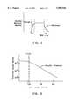
- FIG. 3is a diagram showing eye tissue ablation energy threshold versus pulse width.
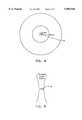
- FIG. 4is a diagram showing the relative diameters of tissue regions removed by laser pulses at the ablation threshold for pulses of approximately 1 ns, 10 ps, and 1 ps duration.
- FIG. 5is a diagram showing the interaction point of a laser beam.
- FIG. 6is a block diagram of the preferred embodiment of the inventive apparatus.
- FIG. 7is a cross-sectional side view of a cornea showing some of the resulting incisions which can be formed in a stroma by the present invention.
- FIG. 8Ais a top view of a cornea, showing the use of the present invention to make radial excisions on the cornea.
- FIG. 8Bis a top view of a cornea, showing the use of the present invention to make transverse-cut excisions on the cornea.
- FIG. 9is a cross-sectional side view of a cornea, showing the use of the present invention to remove tissue to a desired depth d over a predetermined area on the cornea, and showing an alternative method for performing a cornea transplant.
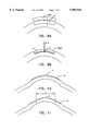
- FIG. 10is a cross-sectional side view of a cornea, showing the use of the present invention to correct myopia.
- FIG. 11is a cross-sectional side view of a cornea, showing the use of the present invention to correct hyperopia.
- FIG. 12is a cross-sectional side view of a cornea, showing the use of the present invention to correct myopia using an alternative method.
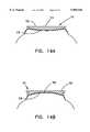
- FIG. 13Ais a cross-sectional side view of a cornea, showing the use of the present invention to correct hyperopia using an alternative method.
- FIG. 13Bis a top view of the cornea of FIG. 13A, showing the use of the perimeter radial cuts to help correct hyperopia.
- FIG. 14Ais a cross-sectional side view of a convex applanator plate applied to an eye.
- FIG. 14Bis a cross-sectional side view of a concave applanator plate applied to an eye.
- the laser apparatus and method disclosed in this inventionis for achieving two principal objectives:
- a definite predetermined depth or volume of tissueis to be ablated.
- the ablated depth per laser pulsemust be controllable and about 5 ⁇ m or less, and preferably about 0.5 ⁇ m or less.
- the present inventionuses short duration laser pulses from about 0.01 to 2 picoseconds to reduce inflicted damage to target tissues.
- the preferred laser systemincludes a Ti 3 .Al 2 O 3 , Cr:LiSrAlF 6 , Nd:YLF, or similar laser with a preferred wavelength of about 400 nm to about 1900 nm.
- the laser beam cross-sectional areais preferably about 10 ⁇ m in diameter. The importance of these characteristics is explained below.
- a fundamental problem of prior art ophthalmic surgical laser systemsis that such systems fail to adequately take into account the interaction of the laser beam with organic tissue in the ablation process, particularly when using relatively transmissive laser wavelengths.
- Laser ablationoccurs when the laser beam intensity, or energy level, is increased beyond a certain threshold level, causing dielectric breakdown.
- the actual ablation conditionsvary depending on the characteristics of a wide range of laser parameters and the composition of the material to be ablated.
- the electronic configuration of the target polymer moleculesmakes a transition to one of its excited electronic states.
- Each polymeris made of hundreds or more of sub-units of smaller molecules called monomers.
- the monomersare made of even smaller units of radicals consisting of combinations of hydrogen, carbon, oxygen, and nitrogen atoms. Depending on the energy level of the laser photons, a polymer can be broken into constituent monomers, radicals, or ionized atoms.
- a single laser photonis not sufficiently energetic to break any molecular bond. Breaking such a bond is a highly non-linear multi-photon process. After absorbing an initial photon, a molecule is promoted to an excited electronic state configuration, with its electrons in higher energy orbits. This state will decay, or "relax", if additional photons are not absorbed to maintain the excited electronic state configuration.
- the excited state electronic orbitalsare the means for energy storage that will eventually fuel the ablation process, and the electronic energy state migration process plays a key role in the dynamics controlling the initiation of the laser ablation. Because photoablation requires multiple photons interacting with organic tissue molecules, "ignition" of ablative action near the threshold condition is determined by a statistical process.
- determination of the average etch depth or volume for laser beam energies near the ablation energy thresholdare derived by measuring actual etch depth or volume after hundreds or sometimes thousands of laser pulses over the same location, and determining an average etch amount per pulse.
- the etch depth or volumecould vary significantly, and most of the laser pulses may not ablate any material at all.
- the ablation threshold for a particular wavelengthis the total integrated energy required for 50% of laser pulses to have an effect.
- the operating energy per pulseis conventionally set at a multiple of the ablation energy threshold level; a factor of 3 to 4 times the ablation energy threshold is usually considered sufficient to achieve satisfactory results.
- the ablation threshold levelis at about 50 mJ/cm 2 ; basically no ablative action is observed at a laser energy density below this threshold level. Accordingly, the typical energy density in an excimer surgical laser beam required for cornea ablation is about 150-250 mJ/cm 2 .
- the slope of the excited state density distribution curvemust be steep.
- the pulse width of the impinging laser beamshould be kept narrow.
- FIG. 1Ais a diagram showing the power density of a square laser pulse versus time for a 5 ns pulse. If the ablation threshold is found to occur at a particular power density (arbitrarily considered to have a value of "1" in FIG. 1), then a higher ablation threshold is required when the pulse is narrowed. That is, the total integrated energy of the shorter laser pulse must approach the total integrated energy of the longer laser pulse. However, it is also known that halving the pulse duration does not require a doubling of the power density of the pulse.
- FIG. 1Bis a diagram showing the power density of a square laser pulse versus time for a 2.5 ns pulse. The ablation threshold is less than twice the ablation threshold of a 5 ns pulse.
- Empirical results obtained from materials damageindicate that a particular ablation threshold can be reached with a pulsed laser beam 100 times shorter in duration than a longer duration pulse when the total integrated energy of the shorter laser pulse is at about 10% of the total integrated energy of the longer pulse.
- FIG. 2is a diagram showing the excited state electron density of eye tissue at a laser beam interaction point. The diagram shows that the excited state electron density is related to the energy density of the incident laser beam. As photons from a laser beam interact with tissue, the electron state of the molecules undergo “charging" to a steady state. The "charging" time t R is related to the electron migration rate. The discharge time is also equal to t R . The charge/discharge time t R is approximately 0.5 to 1 picoseconds.
- the excited state electron densityAfter the initial photons of a laser pulse charge the excited state electron density to a steady state, the remaining photons of the pulse have essentially no effect on such density.
- the steady statearises because energy migrates away from the beam interaction point.
- the energy migration processis counter-balanced by additional laser beam pumping to build up the critical excited state electron density.
- the excited state orbitalsdiffuse from the laser interaction point into the depth of the material (along the laser beam direction).
- the excited state distribution curvewill have less steep a slope compared to the curve from a shorter pulse.
- the present inventionrecognizes that the depth of the tissue layer which has sufficient excited state orbitals to satisfy the ablation threshold condition will be correspondingly deepened. Therefore, the damage inflicted by a longer duration laser pulse is more extensive than the damage inflicted with a shorter duration pulse.
- a longer pulse durationis required to achieve sufficient photon interactions to charge the excited state electron density to a steady state.
- a higher energy densityis required for a laser pulse having a shorter duration.
- more photon interactions per unit of timeoccur, thereby more rapidly charging the excited state electron density to the steady state.
- Less energymigrates away from the laser interaction point. Consequently, the total integrated energy of a narrower pulse need not be as great as the total integrated energy of a longer pulse to achieve the ablation threshold.
- FIG. 3is a diagram showing eye tissue ablation energy threshold versus pulse width. As the laser pulse width reaches about 2 picoseconds, and the energy density of the beam is about 1.0 ⁇ J/(10 ⁇ m) 2 for an 830 nm wavelength, the number of photons is sufficient to maintain a steady state excited state electron density without significant decay. This relationship between pulse duration and constant ablation threshold has been found to exist from about 2 picoseconds down to at least 0.01 picoseconds.
- ablationcan be achieved at a low ablation threshold energy using such extremely short duration laser pulses.
- tissue damage from acoustic shock and kinetic action from dissociated matteris directly proportional to energy deposited at the laser interaction point. If the ablation threshold is achieved at less than the total pulse energy, the remaining energy in the pulse is completely absorbed by the generated plasma, thereby contributing to the explosive effect of the tissue ablation. Both acoustic shock and kinetic action are decreased by reducing the pulse duration.
- FIG. 4is a diagram showing the relative diameters of tissue regions removed by laser pulses at the ablation threshold for pulses of approximately 1 nanosecond, 10 picoseconds, and 0.1 picosecond duration. As can be seen, the range of tissue removal and surrounding tissue damage is substantially less for the shorter pulses (the volume of tissue removed is proportional to energy deposited, which falls off from the center of the interaction point proportionally to the radius cubed).
- the illustrated embodiment of the present inventionuses an 830 nm wavelength for the laser beam, which is generally transmissive in eye tissue.
- a wavelengthcan be generated in known fashion from a broad gain bandwidth (i.e., ⁇ >.sup. ⁇ 1 mm) laser, such as a Ti 3 .Al 2 O 3 , Cr:LiSrAlF 6 , Nd:YLF, or similar laser.
- a broad gain bandwidthi.e., ⁇ >.sup. ⁇ 1 mm
- a Ti 3 .Al 2 O 3 , Cr:LiSrAlF 6 , Nd:YLFor similar laser.
- One such laseris described in co-pending U.S. patent application Ser. No. 07/740,004, filed Aug. 2, 1991, entitled “Two Dimensional Scanner-Amplifier Laser” and assigned to the assignee of the present invention.
- wavelengthscould be used as desired, since absorption and transmission in the eye is a matter of degree.
- less transmissive wavelengthscan be used for procedures at or near the front of the eye, such as the cornea.
- acceptable wavelengthsinclude the ranges of about 400 nm to about 1900 nm, about 2.1 ⁇ m to about 2.8 ⁇ m, and longer than about 3.1 ⁇ m.
- FIG. 5is a diagram showing the interaction point P of a laser beam.
- the portion of the beam above and below the interaction point Placks sufficient energy density to ignite photoablation. Hence, those portions of the laser beam pass through the surrounding tissue without causing damage. Where the beam is focused most tightly (i.e., the focal point), the energy density is sufficient to initiate ablation.
- the laser beam cross-sectional area of the invention at the interaction pointis preferably about 10 ⁇ m in diameter.
- the preferred beam size of the inventioncontrasts with current excimer laser surgical systems, which subject an ablation zone to a surgical beam that is typically 4-6 mm in diameter.
- the beam diametercan be varied to any tolerably achievable smaller or larger dimension, as required by the particular type of surgery. In particular, a range of about 1 ⁇ m to about 30 ⁇ m is preferred.
- Each laser pulse of the type described aboveis preferably directed to its intended location in or on the eye through a laser beam control means, such as the type described in the co-pending, commonly-owned U.S. patent application Ser. No. 07/788,424.
- FIG. 6shows a block diagram of such a laser and control system.
- FIG. 6shows a laser unit 100 for generating an initial laser beam B.
- the laser unit 100is of the type that can outputs a beam rapidly deflectable or scannable under electronic control in two dimensions to any location in an area defined by orthogonal X and Y axes.
- One such laser unitis described in detail in the co-pending, commonly-owned patent application for invention entitled “Two Dimensional Scanner-Amplifier Laser” (U.S. patent application Ser. No. 07/740,004), which is hereby incorporated by reference.
- the initial laser beam Bcomprises a sequence of laser pulses having a pulse repetition rate of about 100 to 100,000 pulses per second.
- the actual number of laser pulses used for a surgeryis determined by the amount of tissue to be removed.
- the laser unit 100includes a seed laser 102 and a scanner-amplifier laser 104.
- the laser media in both the seed laser 102 and the scanner-amplifier 104is a Ti:Al 2 O 3 solid state laser crystal.
- the laser beam BAfter emerging from the laser unit 100, the laser beam B passes through a computer-controllable, motorized zoom lens 106, which provides control over the diameter of the laser beam B.
- the zoom lens 106may be placed in a number of suitable positions along the optical path of the laser beam between the laser unit 100 and a target.
- the motor actuation of the zoom lens 106may be by any known means, such as electrical gear drives or piezoelectric actuators.
- the entire surgical laser apparatusincludes a number of control and safety systems.
- the present inventionincludes means for monitoring and controlling the intensity of the beam, means for blocking the surgical beam in the event of a malfunction, means for monitoring and controlling the laser beam diameter and intensity profile, and means for verifying the two-dimensional (X-Y) scan position of the surgical beam.
- the laser beam Bpasses through a beam intensity controller 112, the output of which is the surgical laser beam S.
- the beam intensity controller 112permits regulation of the energy of each laser pulse so that the etch depth of each pulse may be precisely controlled.
- the beam intensity controller 112is an electro-optical filter, such as an electrically activated Pockels cell in combination with an adjacent polarizing filter.
- the beam intensity controller 112is coupled to a computer control unit 114, which is suitably programmed to vary the intensity of the output surgical laser beam S as required for a particular surgical procedure.
- the degree of beam retardation as a function of applied electrical signalcan be ascertained by standard calibration techniques.
- the preferred location of the beam intensity control unit 112is as shown in FIG. 6. However, the beam intensity control unit 112 can be placed at several suitable locations in the beam path between the laser unit 100 and a target.
- the intensity of the surgical beam Sis regulated to have an ablation energy density of less than or equal to about 5 ⁇ J/(10 ⁇ m) 2 .
- the present inventionoptionally provides for positive feed-back measurement of the beam intensity.
- a partially transmissive beam-splitting mirror 116is placed after the beam intensity controller 112, and the reflected beam R i is directed to a beam intensity sensor 118.
- the beam intensity sensor 118may be simply a photocell, although other elements, such as focussing optics, may be included.
- the intensity of the surgical laser beam Scan be positively measured to verify the proper operation of the beam intensity controller 112.
- the output of the beam intensity sensor 118 as a function of intensity of the surgical laser beam Scan be ascertained by standard calibration techniques.
- the inventive systemalso preferably includes a safety shutter 120, which is coupled to the computer control unit 114.
- the safety shutter 120may be, for example, a mechanically-actuated shutter operated in a "tail-safe" mode.
- the safety shutter 120may include a solenoid-actuated shield that is positively held open by application of electrical energy to the solenoid. Upon command of the computer control unit 114, or failure of the entire system, electrical energy to the solenoid is cut off, causing the solenoid to retract the shield into position to block the path of the surgical laser beam S.
- the safety shutter 120is also useful for temporarily blocking the laser beam S while changing the position of the patient's eye or of the beam itself, without turning the laser beam S completely off.
- the safety shutter 120may include a Pockels cell and polarizer configured as a light valve, with the Pockels cell biased with respect to the polarizer by application of an electrical voltage such that maximum light is normally transmitted by the combination. Cessation of the applied voltage will cause the output of the Pockels cell to become polarized orthogonal to the transmission direction of the polarizer, hence blocking the surgical laser beam S.
- the safety shutter 120 and the beam intensity controller 112may be combined into a single unit.
- any other suitable means for quickly blocking the surgical laser beam S on command or in the event of system failuremay be used to implement the safety shutter 120.
- the safety shutter 120may be placed in a number of suitable positions along the optical path of the laser beam between the laser unit 100 and a target.
- the inventive systemprovides a partially transmissive beam-splitting mirror 122 that reflects part of the beam R d to a beam diameter sensor 124.
- the beam diameter sensor 124may be placed in a number of suitable positions along the optical path of the laser beam between the laser unit 100 and a target.
- the beam diameter sensor 124preferably includes at least a diverging (concave) lens and a converging (convex) lens configured as a magnifying telescope (i.e., the two lenses have a common focal point, with the focal length f 2 of the converging lens being greater than the focal length f 1 of the diverging lens, and having optical centers aligned with the incident laser beam in its un-deflected position).
- the incident beam R denters the diverging lens and exits the converging lens.
- Such a configuration of lenses, while enlarging the incident beamwill also reduce the scan angle of the exiting beam.
- the resulting enlarged beamis directed to a high sensitivity, low contrast imaging device, such as a charge-coupled device (CCD) camera.
- CCDcharge-coupled device
- the converging and diverging lensesare chosen to expand the incident beam R d so that the largest possible diameter for the beam just fits within the imaging device.
- the size of the beamis determined by periodically addressing a central row and a central column of the imaging device and counting the number of pixels on each sampled axis that have been illuminated. By comparing the diameter of the beam in both the X and Y directions, the beam diameter sensor can determine whether the incident laser beam B is approximately circular and has the desired diameter.
- the beam diameter sensor 124can also be used to determine the intensity profile of the laser pulses, since each pixel in the beam diameter sensor 124 can generate an output indicative of the intensity of light incident to the pixel. By comparing pixel values from radially symmetric points in the pixel array, it can be determined if an incident laser pulse or series of pulses has the desired radially symmetric intensity profile, or if the pulses have developed "hot spots" of out-range intensity values.
- the output of the beam diameter sensor 124is coupled to the computer control unit 114.
- the computer control unit 114is in turn coupled to the motorized zoom lens 106, which provides control over the diameter of the laser beam B.
- the computer control unit 114is suitably programmed to vary the diameter of the laser beam as required for a particular surgical procedure.
- the output of the beam diameter sensor 124 as a function of beam diametercan be ascertained by standard calibration techniques.
- This configurationprovides positive feed-back of the beam diameter emanating from the laser unit 100. If the beam diameter sensor 124 detects an out-of-range beam (either diameter or intensity profile), the computer control unit 114 can take appropriate action, including activation of the safety shutter 120.
- the inventive systemprovides a partially transmissive beam-splitting mirror 126 that reflects part of the beam energy R i to a beam location sensor 128.
- the beam location sensor 128preferably includes at least a converging (convex) lens and a diverging (concave) lens configured as a reducing telescope (i.e., the two lenses have a common focal point, with the focal length f 2 of the diverging lens being greater than the focal length f 1 of the converging lens, and having optical centers aligned with the incident laser beam in its un-deflected position).
- the incident beam R ienters the converging lens and exits the diverging lens.
- Such a configuration of lenses, while reducing the incident beamwill also increase the scan angle of the exiting beam.
- the resulting increased-scan angle beamis directed to a silicon photo-detector, such as the position sensing detector, model DLS-20 manufactured by UDT Sensors, Inc. of Hawthorne, Calif.
- the photo-detectorprovides a voltage reading with respect to the two-dimensional (X-Y) position of an illuminating spot at the detector surface.
- the output of the beam location sensor 128is coupled to the computer control unit 114. Calibration of the voltage reading generated from the un-deflected incident beam position on the photo-detector will indicate the origin of the laser beam in the XY-scan plane. Any deflection of the beam from the origin will generate voltage readings indicative of the spot on the photo-detector surface illuminated by the laser beam.
- These voltage readingsare calibrated against the indicated location of the surgical beam as set by the computer control unit 114.
- the output of the beam location sensor 128would be sampled periodically (for example, about 1,000 times per second) and compared to a prepared calibration table in the computer control unit 114 to determine if the actual beam position matches the indicated position.
- This configurationprovides positive feed-back of the beam position emanating from the laser unit 100. If the beam location sensor 128 detects an out-of-position beam, the computer control unit 114 can take appropriate action, including activation of the safety shutter 120.
- the preferred embodiment of the inventive surgical laser apparatusprovides for safe and effective surgery by continuously monitoring all aspects of the condition of the surgical laser beam S, including beam intensity, diameter, and X-Y scan position.
- an eye tracking system 130is placed in the path of the surgical laser beam S, preferably in close proximity to a target eye.
- the eye tracking system 130monitors movement of a patient's eye and adjusts the position of the surgical laser beam S to compensate. Such tracking may be accomplished by providing fiducial marks on the eye and optically tracking movement of said fiducial marks. Deflectable mirrors may then be used to steer the surgical laser beam S.
- An example of one such systemis described in co-pending U.S. patent application Ser. No. 07/788,424, which description is hereby incorporated by reference.
- the present inventionincludes a guide beam unit 132.
- the guide beam unit 132includes a low-power laser with an output of preferably less than 1 milliwatt at initial output and preferably attenuated to the microwatt level for safe usage for direct viewing.
- the low-power lasergenerates a guide beam which is conditioned optically so that it is aligned with the surgical laser beam S and can be used as a indicator of the location of the surgical laser beam S.
- the guide beamcan be used as an element for the alignment of a patient's eye in preparation for surgical procedures.
- the laser surgical system of the present inventioncan perform numerous types of surgical procedures on the eye.
- the focal point of the surgical laser beam Sis placed a known reference location, preferably in the vicinity of the point of surgery.
- the eye tracking system 130is activated. Any eye movement thereafter will be compensated for by a corresponding automatic adjustment of the laser beam position.
- the inventive systemcan perform any and all of the following procedures:
- the inventive systemcan easily create straight line and curved-line excisions, of any predetermined length and depth, at any location determined by a surgeon.
- FIG. 7illustrates some of the resulting excisions which can be formed in the stroma 601 of an eye 600.
- the excisions shown in FIG. 7are merely intended to illustrate a limited number of examples of the types of excisions that can be made using the invention, and are not intended to demonstrate any particular surgical procedure, or to imply that the illustrated excisions are the only relevant types of excisions that can be easily made in accordance with the present invention.
- the excisions illustrated in FIG. 7include a straight channel 603, a curved channel 605, a point 607, a line 609, an interrupted line 611, a curve of varying depth 613, a circular area 615, a square or parallelepiped area 617, or a spiral 619.
- the inventionencompasses any combination of such excisions.
- multiple radial cuts 902equal or partially equal in excision length and with an angular separation between cuts, can be made on the cornea with the present surgical system.
- An excisioncan be made by directing the surgical laser beam S to a predetermined location at the cornea, and removing the desired amount of tissue by controlling the laser beam energy dosage.
- the present inventionprovides options for making an excision with either a wide excision width by using a larger beam spot size on the cornea surface, or a fine excision by using a more focussed beam spot. With the present invention, the depth of each cut can be varied over the length of a predetermined excision.
- the inventioncan also easily generate arcuate cuts or transverse cuts ("T-cuts"), as shown in FIG. 8B.
- T-cutsarcuate cuts or transverse cuts
- excisions in the corneacan be made at effective locations for performing radial keratotomies or making T-cuts or arcuate cuts, to correct myopia, hyperopia, or astigmatism (regular or irregular).
- the inventive systemcan also be used for procedures in cornea transplants.
- a circumcision of the cornea in any predetermined shapee.g., circular, elliptical, polygonal, etc.
- a computer control unit 114calculates the beam location based on the particular shape excision and the amount of laser energy needed to cut through the cornea.
- the second important type of laser-tissue interaction provided by the inventive systemis area ablation, which permits direct sculpting of the corneal surface.
- a local scar or infected tissuecan be removed with the present invention.
- the defective tissueis removed to a desired depth d over a predetermined area on the cornea.
- a donor cornea cap 1001can be cut and ablated ("sculpted") to the desired dimension, curvature, and thickness using the invention described in co-pending U.S. patent application Ser. No. 07/788,424.
- the cap pieceis then transferred to the bared stroma bed and attached by suture, glue, or other appropriate means, in known fashion.
- the capmay be prepared in advance with an appropriate refractive power in a fashion similar to a contact lens. Such a cap can be used to change the refractive power of the eye to correct myopia, hyperopia, or astigmatism (regular or irregular).
- the surgical laser beam Scan be focussed through overlying tissue to an interaction point P, the surgical laser beam S can be used to ablate a layer of tissue beneath the surface of the eye to create an interior chamber A. Accordingly, using such "interior excision” or “intrastromal ablation", a section or segment of the cornea can be “excavated” in this manner, and then a circumferential ablation cut around the perimeter of the area can be made so that the entire segment can be lifted away from the eye as a cap 1002.
- the surgical laser beam Scan be used to sculpt the back side of the material that will form the cap 1002, so as to change the refractive characteristics of the cap 1002.
- the cap 1002can then be cut loose from the eye. If desired, further sculpting can be done directly on the exposed bed of the eye. Thereafter, the cap 1002 can be attached to the open ablated area by sutures or other known methods.
- Another use of the inventionis to produce standard or custom sculpted cornea caps in advance of need.
- the inventioncan be used on a donor cornea or a synthetic cornea substitute to ablate a desired profile to correct for myopia, hyperopia, or astigmatism. Such sculpted caps can then be attached to a properly prepared cornea, in known fashion.
- the curvature of the corneacan be reduced by selectively ablating the cornea such that more tissue is removed at the center portion C of the cornea, with a decreasing amount of tissue being removed towards the periphery P of the cornea.
- the inventive systemcan also be applied to ablate the corneal tissue near the surface of cornea.
- the new desired profile of the eyemay include Bowman's membrane and part of the stromal layer, depending on the amount of refractive correction required.
- the computer control unit 114provides for the sequence, location, and intensity of laser pulses to be deposited.
- the deposition patternis preferably in accordance with the patterns discussed in the section "Method of Depositing Laser Pulses" within the co-pending application.
- correction of myopiamay be performed by ablating material under the central portion C of the cornea.
- the ablation gradient for the removed tissuevaries.
- the material overlying the chamber 1200relaxes, it will reattach to the bottom of the chamber, thus changing the curvature of the eye.
- the objectiveis to increase the curvature of the eye.
- Cornea tissueis removed in an annular ring that is shallow near the center portion C of the cornea and increases in thickness towards the periphery P of the cornea.
- the depth of the removed tissueagain decreases near the periphery of the eye for a smooth transition.
- the etch gradient for the removed tissuevaries.
- the size of the usable central region Rvaries depending on the amount of hyperopic correction.
- hyperopiacan also be corrected by ablating an annular chamber 1301 beneath the surface of the eye centered approximately on the center portion C of the cornea.
- the ablation gradient for the removed tissuevaries.
- a circumferential excision 1302is made around the bottom rim of the annular chamber 1301 to free an edge of the outer portion of the annular chamber 1301 from attachment to the eye, thereby creating a flap 1303.
- the flap 1303will relax to the bottom of the chamber, thus changing the curvature of the eye.
- small perimeter radial cuts 1304shown in FIG. 13B) may be made in the edge of the flap 1303 to further relax the flap and cause it to adhere to the bottom of the chamber 1301 formed by the interior excision.
- the inventionmay be used to correct regular or irregular astigmatism, or complex refractive errors.
- the amount and distribution of tissue to be removed from various locations within the stromais determined by the amount of correction required.
- the inventionis particularly useful for the correction of asymmetric refractive errors. Irregular distortions may result from poor matching of a cornea from a transplant, uneven suturing, or from imperfect refractive surgical procedures such as lamellar keratomileusis or epikeratophakia.
- the inventive systemcan direct the surgical laser beam to any desired location to sculpt the cornea according to a predetermined shape. The surgical laser beam thus can be applied to smooth out an irregular corneal profile.
- the third important type of laser interaction provided by the inventive systemis intraocular excisions.
- the inventioncan be used to excise or photoablate regions within the cornea, capsule, lens, vitreoretinal membrane, and other structures within the eye.
- the present inventionis useful for performing surgical procedures to correct glaucoma by creating a one or more openings through an iris to release fluids from the posterior chamber which create undesirable pressure behind the cornea.
- one or more excisionsmay be created in the posterior or anterior capsule to permit removal of material from the capsule and to implant an intraocular lens (IOL) or any other lens-like material or structure which can be in fluid or gel form.
- IOLintraocular lens
- a cataractal lenscan be ablated and liquified.
- the inventive procedurecan be used prior to an IOL implant for cataract conditioning.
- portions of the retinal membrane which create tension on the retinamay be cut to relieve such tension.
- portions of the retinamay be operated upon to remove harmful tissue. Accordingly, the invention precisely controls and determines the location of the interaction point of a surgical laser beam, and controls the shape of the cornea during ophthalmic surgery.
- a ophthalmic surgical laser systemwhich can be adapted for use with the present invention to provide for precisely controlling and determining the location of the interaction point of a surgical laser beam, and for controlling the shape of the cornea during ophthalmic surgery, is set forth in co-pending U.S. patent application Ser. No. 07/967,253, entitled “METHOD AND APPARATUS FOR OPHTHALMIC SURGERY" and assigned to the assignee of the present invention.
- a transparent applanator plateis placed in contact with the cornea of a patient's eye.
- the applanator platecreates a fixed positional frame of reference from which a laser beam control system can determine the desired point or points at which to focus the surgical laser beam, and thereby direct an interaction point of the beam to very precisely defined locations within the patient's eye.
- the surface of the applanator plate in contact with the patient's eyecan be planar, concave, or convex, with either a spheric or aspheric curvature, a compound curve, or any other shape chosen by the surgeon. Applying the applanator plate to the cornea of the patient's eye causes the cornea to conform to the shape of the applanator plate.
- FIG. 14Ashows a cross-sectional side view of a convex applanator plate 111.
- the applanator plate 111has at least two surfaces, a tip surface 112 and a corneal surface 113.
- the applanator plate 111is placed in contact with the corneal epithelium 115 and deforms the cornea to conform to the convex shape of the corneal surface 113.
- FIG. 14Bshows a cross-sectional side view of a concave applanator plate 111 applied to an eye.
- the applanator plate 111is placed in contact with the corneal epithelium 115 and deforms the cornea to conform to the concave shape of the corneal surface 113.
- a surgical tip at the distal end of an articulated arm having flexible jointsis placed in contact with the tip surface 112 of the applanator plate 111 and follows any motion of the patient's eye.
- the articulated armis coupled to a surgical laser source including a laser beam control system, such as the system described in co-pending patent applications filed by the present inventor for inventions entitled “Two Dimensional Scanner-Amplifier Laser” (U.S. patent application Ser. No. 07/740,004), and “Method of, and Apparatus for, Surgery of the Cornea" (U.S. application Ser. No. 07/788,424).
- the surgical laser sourcealso includes the source of the laser beam.
- the articulated armdirects the laser beam to the surgical tip, translating the motion of the beam relative to a reference frame fixed to the surgical laser source to a reference frame fixed with respect to the applanator plate to which the surgical tip is in contact. Since the shape of the cornea conforms to the contour of corneal surface 113 of the applanator plate 111, incisions of various shapes can be made by selecting an appropriate applanator plate and controlling the surgical beam to move linearly with respect to the fixed frame by the applanator plate.
- the applanator plate 111also provides a means to control the contour of the index of refraction boundary between the corneal epithelium 115 of the patient's eye and the air. Controlling the contour of this boundary reduces the distortion of the surgical laser beam which would otherwise be present due to the curvature of the outer surface of the epithelium and the difference in the index of refraction between the air and the stroma underlying the epithelium.
- the index of refraction of the applanator plateis preferably closely matched to the index of refraction of the cornea (i.e., index of approximately 1.38).
- the tip surface 112 of the applanator plate 111is selectively shaped to provide a desirable contour at the boundary between the index of refraction of the stroma and air.
- the applanator plate 111serves at least three purposes: (1) to provide a positional reference for a surgical laser; (2) to control the shape of the patient's cornea during a surgical laser procedure; and (3) to provide a boundary between the epithelium and air, the contour of which can be controlled to reduce the distortion of the surgical laser beam.
- the applanator plate 111provides even greater control of tissue removal.
- the preferred method of performing a surface ablation of cornea tissue or other organic materialsuses a laser source which has the characteristics of providing a shallow ablation depth or region (about 0.2 ⁇ m to about 5.0 ⁇ m), a low ablation energy density threshold (about 0.2 to 5 ⁇ J/(10 ⁇ m) 2 , and extremely short laser pulses (having a duration of about 0.01 picoseconds to about 2 picoseconds per pulse) to achieve precise control of tissue removal.
- the laser beam cross-sectional areais preferably about 10 ⁇ m in diameter.
- the preferred laser systemincludes a broad gain bandwidth laser, such as Ti 3 Al 2 O 3 , Cr:LiSrAlF 6 , Nd:YLF, or similar lasers, with a preferred wavelength range of about 400 nm to about 1900 nm, which is generally transmissive in eye tissue.
- a broad gain bandwidth lasersuch as Ti 3 Al 2 O 3 , Cr:LiSrAlF 6 , Nd:YLF, or similar lasers, with a preferred wavelength range of about 400 nm to about 1900 nm, which is generally transmissive in eye tissue.
- the surgical beamcan be directed to remove cornea tissue in a predetermined amount and at a predetermined location such that the cumulative effect is to remove defective or non-defective tissue, or to change the curvature of the cornea to achieve improved visual acuity.
- Excisions on the corneacan be make in any predetermined length and depth, and in straight line or in curved patterns.
- circumcisions of tissuecan be made to remove an extended area, as in a cornea transplant.
- the inventioncan be used to excise or photoablate regions within the cornea, capsule, lens, vitreoretinal membrane, and other structures within the eye.
- the present inventionprovides an improved method of eye surgery which has accurate control of tissue removal, flexibility of ablating tissue at any desired location with predetermined ablation depth, an optically smooth finished surface after the surgery, and a gentle surgical beam for laser ablation action.
Landscapes
- Optics & Photonics (AREA)
- Physics & Mathematics (AREA)
- Health & Medical Sciences (AREA)
- Engineering & Computer Science (AREA)
- Ophthalmology & Optometry (AREA)
- Heart & Thoracic Surgery (AREA)
- General Health & Medical Sciences (AREA)
- Mechanical Engineering (AREA)
- Surgery (AREA)
- Biomedical Technology (AREA)
- Plasma & Fusion (AREA)
- Vascular Medicine (AREA)
- Life Sciences & Earth Sciences (AREA)
- Animal Behavior & Ethology (AREA)
- Nuclear Medicine, Radiotherapy & Molecular Imaging (AREA)
- Public Health (AREA)
- Veterinary Medicine (AREA)
- Laser Surgery Devices (AREA)
- Laser Beam Processing (AREA)
- Lasers (AREA)
- Materials For Medical Uses (AREA)
- Treatments Of Macromolecular Shaped Articles (AREA)
- Manufacture Of Macromolecular Shaped Articles (AREA)
Abstract
Description
Claims (36)
Priority Applications (11)
| Application Number | Priority Date | Filing Date | Title |
|---|---|---|---|
| US08/051,033US5984916A (en) | 1993-04-20 | 1993-04-20 | Ophthalmic surgical laser and method |
| EP94914859AEP0700310B1 (en) | 1993-04-20 | 1994-04-20 | Improved ophthalmic surgical laser |
| ES03077774TES2287407T3 (en) | 1993-04-20 | 1994-04-20 | ENHANCED OPHTHALMIC SURGICAL LASER. |
| AT03077774TATE363259T1 (en) | 1993-04-20 | 1994-04-20 | IMPROVED OPHTHALMOSURGICAL LASER |
| DE69433322TDE69433322T2 (en) | 1993-04-20 | 1994-04-20 | IMPROVED OPHTHALMOSURGICAL LASER |
| EP03077774AEP1402860B1 (en) | 1993-04-20 | 1994-04-20 | Improved ophthalmic surgical laser |
| PCT/US1994/004362WO1994025107A1 (en) | 1993-04-20 | 1994-04-20 | Improved ophthalmic surgical laser and method |
| AU67098/94AAU6709894A (en) | 1993-04-20 | 1994-04-20 | Improved ophthalmic surgical laser and method |
| AT94914859TATE253880T1 (en) | 1993-04-20 | 1994-04-20 | IMPROVED OPHTHALMOSURGICAL LASER |
| DE69434984TDE69434984T2 (en) | 1993-04-20 | 1994-04-20 | Improved ophthalmic surgical laser |
| US08/287,000US6325792B1 (en) | 1991-11-06 | 1994-08-08 | Ophthalmic surgical laser and method |
Applications Claiming Priority (1)
| Application Number | Priority Date | Filing Date | Title |
|---|---|---|---|
| US08/051,033US5984916A (en) | 1993-04-20 | 1993-04-20 | Ophthalmic surgical laser and method |
Related Parent Applications (1)
| Application Number | Title | Priority Date | Filing Date |
|---|---|---|---|
| US96806092AContinuation-In-Part | 1991-11-06 | 1992-10-26 |
Related Child Applications (1)
| Application Number | Title | Priority Date | Filing Date |
|---|---|---|---|
| US08/287,000Continuation-In-PartUS6325792B1 (en) | 1991-11-06 | 1994-08-08 | Ophthalmic surgical laser and method |
Publications (1)
| Publication Number | Publication Date |
|---|---|
| US5984916Atrue US5984916A (en) | 1999-11-16 |
Family
ID=21968953
Family Applications (1)
| Application Number | Title | Priority Date | Filing Date |
|---|---|---|---|
| US08/051,033Expired - LifetimeUS5984916A (en) | 1991-11-06 | 1993-04-20 | Ophthalmic surgical laser and method |
Country Status (7)
| Country | Link |
|---|---|
| US (1) | US5984916A (en) |
| EP (2) | EP0700310B1 (en) |
| AT (2) | ATE253880T1 (en) |
| AU (1) | AU6709894A (en) |
| DE (2) | DE69433322T2 (en) |
| ES (1) | ES2287407T3 (en) |
| WO (1) | WO1994025107A1 (en) |
Cited By (253)
| Publication number | Priority date | Publication date | Assignee | Title |
|---|---|---|---|---|
| WO2000056253A1 (en)* | 1999-03-23 | 2000-09-28 | Fugo Richard J | A method of altering the shape of the cornea of the eye |
| US6146405A (en)* | 1999-02-11 | 2000-11-14 | Johnston; Robert M. | Ophthalmic applanator |
| US6245059B1 (en)* | 1999-04-07 | 2001-06-12 | Visx, Incorporated | Offset ablation profiles for treatment of irregular astigmation |
| US6280436B1 (en)* | 1999-08-10 | 2001-08-28 | Memphis Eye & Cataract Associates Ambulatory Surgery Center | Eye tracking and positioning system for a refractive laser system |
| US6312422B1 (en)* | 1998-03-30 | 2001-11-06 | Carl Zeiss Jena Gmbh | Process and arrangement for monitoring and controlling the treatment parameters in an ophthalmic treatment device |
| WO2001006908A3 (en)* | 1999-07-23 | 2001-11-15 | Leon C Lahaye | Method and apparatus for monitoring laser surgery |
| DE10024079A1 (en)* | 2000-05-17 | 2001-11-22 | Asclepion Meditec Ag | Determining energy and position of pulsed laser beam of ophthalmologic excimer laser for cornea surgery, deflects beam periodically onto measurement sensor |
| US6350272B1 (en)* | 2000-03-20 | 2002-02-26 | Glenn Kawesch | Method and apparatus for cutting an oblong corneal flap |
| USRE37585E1 (en)* | 1994-04-08 | 2002-03-19 | The Regents Of The University Of Michigan | Method for controlling configuration of laser induced breakdown and ablation |
| US20020103482A1 (en)* | 2001-01-29 | 2002-08-01 | Scholler Gordon Scott | Applanation lens and method for ophthalmic surgical applications |
| US6451006B1 (en)* | 2001-02-14 | 2002-09-17 | 20/10 Perfect Vision Optische Geraete Gmbh | Method for separating lamellae |
| WO2002076319A1 (en)* | 2001-03-26 | 2002-10-03 | Lahaye Leon C | Method and apparatus for monitoring laser surgery |
| EP1252872A1 (en)* | 2001-04-25 | 2002-10-30 | 20/10 Perfect Vision Optische Geraete GmbH | Apparatus for creating a corneal reference mark |
| EP1260202A1 (en)* | 2001-05-18 | 2002-11-27 | Wavelight Laser Technologie AG | Laser system for corneal transplant surgery |
| US6489589B1 (en)* | 1994-02-07 | 2002-12-03 | Board Of Regents, University Of Nebraska-Lincoln | Femtosecond laser utilization methods and apparatus and method for producing nanoparticles |
| US6497701B2 (en)* | 1999-04-30 | 2002-12-24 | Visx, Incorporated | Method and system for ablating surfaces with partially overlapping craters having consistent curvature |
| US20030053219A1 (en)* | 2001-07-30 | 2003-03-20 | Manzi David J. | Lens system and method |
| US6551306B1 (en)* | 1999-04-13 | 2003-04-22 | Cesar C. Carriazo | Refractive laser ablation through topography |
| WO2002076355A3 (en)* | 2001-03-27 | 2003-08-28 | Wavelight Laser Technologie Ag | Method for treatment and diagnosis of eye tissues |
| WO2002078585A3 (en)* | 2001-03-30 | 2003-09-12 | Zeiss Carl Meditec Ag | Device and method for the laser treatment of organic material |
| US20030208265A1 (en)* | 2001-05-08 | 2003-11-06 | Arthur Ho | Supplementary endo-capsular lens and method of implantation |
| EP1316298A3 (en)* | 2001-11-28 | 2003-11-12 | 20/10 Perfect Vision Optische Geraete GmbH | An apparatus for creating a corneal flap |
| US20030212387A1 (en)* | 2002-03-23 | 2003-11-13 | Intralase Corp. | System and method for improved material processing using a laser beam |
| EP1364632A1 (en)* | 2002-05-24 | 2003-11-26 | 20/10 Perfect Vision Optische Geraete GmbH | Cornea contact system for laser surgery |
| US20030229339A1 (en)* | 2001-10-12 | 2003-12-11 | Josef Bille | Method and apparatus for intrastromal refractive surgery |
| US20030236516A1 (en)* | 2002-06-24 | 2003-12-25 | Keiki Okamoto | Corneal-ablation-amount determining apparatus and a corneal surgery apparatus |
| US20040010310A1 (en)* | 2002-07-12 | 2004-01-15 | Peyman Gholam A. | Method and apparatus for correcting the refraction of an intraocular lens after implantation in the eye |
| US20040015194A1 (en)* | 2000-03-15 | 2004-01-22 | Resolution Medical, Inc. | Multi-electrode panel system for sensing electrical activity of the heart |
| WO2004017878A1 (en) | 2002-08-20 | 2004-03-04 | Quintis Gmbh | Laser-based device for non-mechanical, three-dimensional trepanation during cornea transplants |
| WO2004026198A2 (en) | 2002-08-23 | 2004-04-01 | Carl Zeiss Meditec Ag | Device and method for measuring an optical penetration in a tissue |
| US20040225284A1 (en)* | 2001-01-29 | 2004-11-11 | Webb R. Kyle | Ocular fixation and stabilization device for ophthalmic surgical applications |
| US20040257529A1 (en)* | 2001-05-23 | 2004-12-23 | David Thomas | System and method for reconstruction of aberrated wavefronts |
| US20050000952A1 (en)* | 2003-05-19 | 2005-01-06 | Harter Donald J. | Focusless micromachining |
| EP1302186A3 (en)* | 2001-10-12 | 2005-02-02 | 20/10 Perfect Vision Optische Geraete GmbH | A device for performing refractive surgery |
| DE10332815A1 (en)* | 2003-07-18 | 2005-02-10 | Carl Zeiss Meditec Ag | Method and apparatus for forming curved cut surfaces in a transparent material |
| WO2005011547A1 (en) | 2003-07-25 | 2005-02-10 | Carl Zeiss Meditec Ag | Device and method for forming curved cuts in a transparent material |
| WO2005011546A1 (en)* | 2003-07-25 | 2005-02-10 | Carl Zeiss Meditec Ag | Method and device for forming a closed, curved cut surface |
| DE10334109A1 (en)* | 2003-07-25 | 2005-02-17 | Carl Zeiss Meditec Ag | Method of forming cuts in a transparent material such as the cornea of the eye in laser surgery using an arrangement of partial grids |
| US20050085800A1 (en)* | 2002-01-10 | 2005-04-21 | Matthias Lenzner | Device and procedure for refractive laser surgery |
| US20050107774A1 (en)* | 1999-05-03 | 2005-05-19 | Lin J. T. | Methods and apparatus for presbyopia correction using ultraviolet and infrared lasers |
| US20050107773A1 (en)* | 2002-01-18 | 2005-05-19 | Carl Zeiss Meditec Ag | Femtosescond laser system for the exact manipulation of material and tissues |
| WO2005058216A1 (en) | 2003-12-16 | 2005-06-30 | Carl Zeiss Meditec Ag | Laser device and method for machining material using laser radiation |
| US20050251114A1 (en)* | 2004-04-16 | 2005-11-10 | Dirk Muhlhoff | Device and method for detection of eye movements |
| US20050273088A1 (en)* | 2002-06-27 | 2005-12-08 | Gerhard Youssefi | Myopia correction enhancing biodynamic ablation |
| US20060000812A1 (en)* | 2004-07-02 | 2006-01-05 | Jan Weber | Method and apparatus for controlling and adjusting the intensity profile of a laser beam employed in a laser welder for welding polymeric and metallic components |
| US7004953B2 (en) | 2001-07-23 | 2006-02-28 | Fos Holding S.A. | Device for separating the epithelium layer from the surface of the cornea of an eye |
| EP1649843A1 (en)* | 2004-10-22 | 2006-04-26 | Ligi Tecnologie Medicali S.p.A. | Photoablative laser with controllable pulse release frequency |
| US20060095023A1 (en)* | 2004-11-01 | 2006-05-04 | Frieder Loesel | Time-resolved scanning patterns for intrastromal surgery |
| US20060106371A1 (en)* | 2002-08-23 | 2006-05-18 | Dirk Muhlhoff | Device and method for meansuring an optical penetration in a tissue |
| US20060106372A1 (en)* | 2004-11-12 | 2006-05-18 | Tobias Kuhn | Systems and methods for intrastromal scanning patterns |
| US20060155265A1 (en)* | 1995-03-20 | 2006-07-13 | Intralase Corp. | Method of corneal surgery by laser incising a contoured corneal flap |
| WO2006074898A1 (en) | 2005-01-11 | 2006-07-20 | Carl Zeiss Meditec Ag | Safety mechanism for a laser treatment unit |
| US20060195076A1 (en)* | 2005-01-10 | 2006-08-31 | Blumenkranz Mark S | Method and apparatus for patterned plasma-mediated laser trephination of the lens capsule and three dimensional phaco-segmentation |
| US20060217688A1 (en)* | 1991-11-06 | 2006-09-28 | Lai Shui T | Method and Apparatus for Laser Surgery of the Cornea |
| US20060276776A1 (en)* | 2005-06-01 | 2006-12-07 | Lin J T | Method and system for two-step customized cornea reshaping using ultraviolet infrared lasers |
| US20070010803A1 (en)* | 2003-10-23 | 2007-01-11 | Mark Bischoff | Laser machining |
| US20070034616A1 (en)* | 2003-07-22 | 2007-02-15 | Mark Bischoff | Method for processing materials with laser pulses having a large spectral bandwidth and device for carrying out said method |
| US20070055220A1 (en)* | 2003-11-14 | 2007-03-08 | Jui-Teng Lin | Methods and systems for treating presbyopia via laser ablation |
| US20070078447A1 (en)* | 2004-12-17 | 2007-04-05 | Martin Weinacht | Devices and methods for separating layers of materials having different ablation thresholds |
| WO2007042190A2 (en) | 2005-10-14 | 2007-04-19 | Carl Zeiss Meditec Ag | Device and method for materials processing using laser radiation |
| US20070088409A1 (en)* | 2005-10-14 | 2007-04-19 | Carl Zeiss Meditec Ag | Device and method for material processing by means of laser radiation |
| US20070088342A1 (en)* | 2005-10-19 | 2007-04-19 | Mazaheri Michael M | Mazaheri lasik method for visual enhancement |
| US20070093796A1 (en)* | 2005-10-24 | 2007-04-26 | Intralase Corp. | Disposable patient interface |
| US7220256B2 (en) | 2001-03-13 | 2007-05-22 | Hobart James L | Laser system and method for treatment of biological tissues |
| EP1810646A1 (en) | 2006-01-23 | 2007-07-25 | SIE AG, Surgical Instrument Engineering | Apparatus for protecting tissue during eye surgery |
| US20070173793A1 (en)* | 2006-01-23 | 2007-07-26 | Sie Ag Surgical Instrument Engineering | Device and method for protecting tissue in the treatment of eyes |
| US20070179478A1 (en)* | 2004-02-25 | 2007-08-02 | Dobschal Hans-Juergen | Contact element for laser machining |
| US20070193987A1 (en)* | 2004-03-23 | 2007-08-23 | Mark Bischoff | Material Machining Device And Method |
| WO2007106326A2 (en) | 2006-03-14 | 2007-09-20 | Amo Development Llc | System and method for ophthalmic laser surgery on a cornea |
| US20070237620A1 (en)* | 2003-11-19 | 2007-10-11 | Muehlhoff Dirk | Adapter for Mechanically Coupling a Laser Processing Device to an Object |
| US20070253083A1 (en)* | 2003-11-14 | 2007-11-01 | Dirk Muhlhoff | Adapter for Coupling a Laser Processing Device to an Object |
| US20070258046A1 (en)* | 2006-02-14 | 2007-11-08 | Lai Shui T | Subjective Wavefront Refraction Using Continuously Adjustable Wave Plates of Zernike Function |
| US20070291224A1 (en)* | 2006-06-15 | 2007-12-20 | Lai Shui T | High Visual Acuity Contact Lenses |
| USRE40002E1 (en) | 1998-11-10 | 2008-01-15 | Surgilight, Inc. | Treatment of presbyopia and other eye disorders using a scanning laser system |
| US20080037135A1 (en)* | 2006-07-25 | 2008-02-14 | Lai Shui T | Method of Making High Precision Optics Having a Wavefront Profile |
| US20080039825A1 (en)* | 2006-07-26 | 2008-02-14 | Lai Shui T | Intrastromal Surgery Correcting Low Order and High Order Aberrations of the Eye |
| US20080058841A1 (en)* | 2006-09-05 | 2008-03-06 | Kurtz Ronald M | System and method for marking corneal tissue in a transplant procedure |
| US20080058777A1 (en)* | 2006-09-05 | 2008-03-06 | Intralase Corp. | System and method for resecting corneal tissue using non-continuous initial incisions |
| WO2008030698A2 (en) | 2006-09-05 | 2008-03-13 | Amo Development, Llc | System and method for resecting corneal tissue |
| USRE40184E1 (en) | 1999-05-03 | 2008-03-25 | Surgilight, Inc. | Refractive surgery and presbyopia correction using infrared and ultraviolet lasers |
| US20080082085A1 (en)* | 2006-09-08 | 2008-04-03 | Krasutsky Nicholas J | Time division multiplexed, beam combining for laser signal generation |
| WO2008055697A1 (en) | 2006-11-10 | 2008-05-15 | Carl Zeiss Meditec Ag | Device for the corrective surgery of defective vision of an eye, method for generating control data therefor, and method for corrective surgery of defective vision of an eye |
| US20080144038A1 (en)* | 2006-12-19 | 2008-06-19 | Richard Alan Leblanc | Performance and accuracy assessment system for refractive laser systems and associated methods |
| US20080147052A1 (en)* | 2003-06-02 | 2008-06-19 | Carl Zeiss Meditec Ag | Method and apparatus for precision working of material |
| USRE40420E1 (en)* | 1999-08-26 | 2008-07-01 | Carl Zeiss Meditec Ag | Method and device for treating opaqueness and/or hardening of a closed eye |
| US20080183159A1 (en)* | 2005-08-25 | 2008-07-31 | Dirk Preuss | Contact glass for ophtalmologic surgery |
| US20080212623A1 (en)* | 2005-10-14 | 2008-09-04 | Mark Bischoff | Device and method for material processing by means of laser radiation |
| US20080212024A1 (en)* | 2006-09-18 | 2008-09-04 | Lai Shui T | Customized contact lenses for reducing aberrations of the eye |
| US20080228177A1 (en)* | 2005-11-08 | 2008-09-18 | Friedrich Moritz | System and Method for Correction of Ophthalmic Refractive Errors |
| US20080234707A1 (en)* | 2005-08-25 | 2008-09-25 | Carl Zeiss Meditec Ag | Contact Glass for Ophthalmic Surgery |
| US20080249514A1 (en)* | 1999-10-21 | 2008-10-09 | Kristian Hohla | Method and Apparatus for Multi-Step Correction of Ophthalmic Refractive Errors |
| DE102007017119A1 (en) | 2007-04-11 | 2008-10-16 | Carl Zeiss Meditec Ag | Apparatus and method for material processing by means of laser radiation |
| US20080269731A1 (en)* | 2003-11-19 | 2008-10-30 | Casimir Andrew Swinger | Method and apparatus applying patient-verified prescription of high order aberrations |
| US20080281303A1 (en)* | 2007-03-13 | 2008-11-13 | William Culbertson | Method and apparatus for creating ocular surgical and relaxing incisions |
| US20080319428A1 (en)* | 2006-11-10 | 2008-12-25 | Carl Zeiss Meditec Ag | Treatment apparatus for surgical correction of defective eyesight, method of generating control data therefore, and method for surgical correction of defective eyesight |
| US20090036880A1 (en)* | 2005-07-08 | 2009-02-05 | Mark Bischoff | Device and Method for Changing a Lens Implanted Into an Eye |
| US20090088734A1 (en)* | 2007-09-28 | 2009-04-02 | Eos Holdings, Llc | Laser-assisted thermal separation of tissue |
| US20090105696A1 (en)* | 2006-02-22 | 2009-04-23 | Lutronic Corporation | Nd:yag laser for removing fatty tissue |
| DE102007053283A1 (en) | 2007-11-08 | 2009-05-14 | Carl Zeiss Meditec Ag | A treatment device for operative vision correction of an eye, a method for generating control data therefor and methods for surgical correction of defective vision of an eye |
| DE102007053281A1 (en) | 2007-11-08 | 2009-05-14 | Carl Zeiss Meditec Ag | A treatment device for operative vision correction of an eye, a method for generating control data therefor and methods for surgical correction of defective vision of an eye |
| US20090157063A1 (en)* | 2007-12-17 | 2009-06-18 | Luis Antonio Ruiz | Method patterns for intrastromal refractive surgery |
| US20090157061A1 (en)* | 2007-12-17 | 2009-06-18 | Luis Antonio Ruiz | Method for intrastromal refractive surgery |
| US20090188901A1 (en)* | 2006-04-10 | 2009-07-30 | Board Of Trustees Of Michigan State University | Laser Material Processing System |
| DE102008005053A1 (en) | 2008-01-18 | 2009-07-30 | Rowiak Gmbh | Laser correction of vision defects on the natural eye lens |
| US20090234335A1 (en)* | 2006-03-17 | 2009-09-17 | Amo Manufacturing Usa, Llc | Intrastromal refractive correction systems and methods |
| DE102008017293A1 (en) | 2008-04-04 | 2009-10-08 | Carl Zeiss Meditec Ag | A method of generating control data for ophthalmic surgery and ophthalmic surgical apparatus and methods |
| DE102008017772A1 (en) | 2008-04-04 | 2009-10-08 | Carl Zeiss Meditec Ag | Method and apparatus for forming cut surfaces in a transparent material |
| DE102008017771A1 (en) | 2008-04-04 | 2009-10-08 | Carl Zeiss Meditec Ag | Curved sectional areas smoothing method for cornea of eye of patient, involves defining partial volume by curved sectional areas produced by excimer laser, and interrupting sectional areas after removing of partial volume |
| US20090264874A1 (en)* | 2006-08-02 | 2009-10-22 | Ernst Hegels | Method and apparatus for calculating a laser shot file for use in a refractive excimer laser |
| US20090299345A1 (en)* | 2008-05-27 | 2009-12-03 | Bille Josef F | System and method for reshaping a cornea using a combination of liob and structural change procedures |
| US20090306635A1 (en)* | 2006-08-02 | 2009-12-10 | Ernst Hegels | Method and apparatus for calculating a laser shot file for use in an excimer laser |
| US20090318906A1 (en)* | 2005-11-17 | 2009-12-24 | Wavelight Ag | Assembly and Method for Performing Surgical Laser Treatments of the Eye |
| US7655003B2 (en)* | 2005-06-22 | 2010-02-02 | Smith & Nephew, Inc. | Electrosurgical power control |
| WO2010012596A1 (en)* | 2008-08-01 | 2010-02-04 | Technolas Perfect Vision Gmbh | Combination of excimer laser ablation and femtosecond laser technology |
| US20100042083A1 (en)* | 2006-03-27 | 2010-02-18 | Lutronic Corporation | Control method and structure of laser beam irradiation by using a contact sensor |
| US20100087802A1 (en)* | 2007-04-26 | 2010-04-08 | Carl Zeiss Meditec Ag | Cornea transplantation |
| DE102008056489A1 (en) | 2008-11-06 | 2010-05-12 | Carl Zeiss Meditec Ag | Method for treating the incision surfaces in the cornea comprises forming a partial volume and subjecting at least one incision surface to a radiation from an additional radiation source after removing the volume |
| WO2010072394A1 (en) | 2008-12-23 | 2010-07-01 | Carl Zeiss Meditec Ag | Device for swept-source optical coherence domain reflectometry |
| US20100174274A1 (en)* | 2009-01-06 | 2010-07-08 | Bille Josef F | Minimizing the side-effects of refractive corrections using statistically determined irregularities in intrastromal incisions |
| US20100191228A1 (en)* | 2009-01-27 | 2010-07-29 | Luis Antonio Ruiz | System and Method for Refractive Surgery with Augmentation by Intrastromal Corrective Procedures |
| US20100191229A1 (en)* | 2009-01-27 | 2010-07-29 | Bille Josef F | Methods for Employing Intrastromal Corrections in Combination with Surface Refractive Surgery to Correct Myopic/Hyperopic Presbyopia |
| US20100191227A1 (en)* | 2009-01-27 | 2010-07-29 | Bille Josef F | System and Method for Correcting Higher Order Aberrations with Changes in Intrastromal Biomechanical Stress Distributions |
| US20100217247A1 (en)* | 2009-02-20 | 2010-08-26 | Bille Josef F | System and Methods for Minimizing Higher Order Aberrations Introduced During Refractive Surgery |
| DE102009015911A1 (en) | 2009-04-03 | 2010-10-07 | Carl Zeiss Meditec Ag | Device and method for removing a lenticle from the cornea |
| US20100280503A1 (en)* | 2007-03-19 | 2010-11-04 | Christof Donitzky | Laser system that is gentle on the eyes, for refractive surgery |
| US20110022037A1 (en)* | 2009-01-06 | 2011-01-27 | Bille Josef F | System and Method for Minimizing the Side Effects of Refractive Corrections Using Line or Dot Cuts for Incisions |
| EP2298255A1 (en) | 2006-11-10 | 2011-03-23 | Carl Zeiss Meditec AG | Planning device for preparing control data for a treatment device for operatively correcting defective vision, treatment device for operatively correcting defective vision and method for preparing control date therefor |
| US20110137300A1 (en)* | 2008-06-16 | 2011-06-09 | Gerhard Youssefi | Treatment pattern monitor |
| US20110172649A1 (en)* | 2010-01-08 | 2011-07-14 | Optimedica Corporation | Method and system for modifying eye tissue and intraocular lenses |
| US20110202046A1 (en)* | 2010-01-22 | 2011-08-18 | Optimedica Corporation | Method and apparatus for automated placement of scanned laser capsulorhexis incisions |
| US20110208172A1 (en)* | 2008-08-28 | 2011-08-25 | Gerhard Youssefi | Eye measurement and modeling techniques |
| US8048064B2 (en) | 2005-12-23 | 2011-11-01 | Lutronic Corporation | Method of curing inflammatory acne by using carbon lotion and pulsed laser |
| WO2011152861A3 (en)* | 2010-06-01 | 2012-04-12 | Gholam Peyman | Laser-based methods and systems for performing corneal surgery |
| EP2468174A1 (en) | 2006-05-08 | 2012-06-27 | Shui T. Lai | Subjective wavefront refraction using continuously adjustable wave plates of Zernike function |
| US8262646B2 (en) | 2006-01-20 | 2012-09-11 | Lensar, Inc. | System and method for providing the shaped structural weakening of the human lens with a laser |
| WO2012126053A1 (en)* | 2011-03-21 | 2012-09-27 | Adventus Technology, Inc. | Restoration of accommodation by lens refilling |
| US8382745B2 (en) | 2009-07-24 | 2013-02-26 | Lensar, Inc. | Laser system and method for astigmatic corrections in association with cataract treatment |
| US8409177B1 (en) | 2005-10-13 | 2013-04-02 | Shui T. Lai | Intrastromal refractive surgery by inducing shape change of the cornea |
| US8465478B2 (en) | 2009-07-24 | 2013-06-18 | Lensar, Inc. | System and method for performing LADAR assisted procedures on the lens of an eye |
| US8480659B2 (en) | 2008-07-25 | 2013-07-09 | Lensar, Inc. | Method and system for removal and replacement of lens material from the lens of an eye |
| US8500723B2 (en) | 2008-07-25 | 2013-08-06 | Lensar, Inc. | Liquid filled index matching device for ophthalmic laser procedures |
| US8540703B2 (en) | 2005-12-23 | 2013-09-24 | Lutronic Corporation | Methods for treating skin conditions using laser |
| US8556425B2 (en) | 2010-02-01 | 2013-10-15 | Lensar, Inc. | Purkinjie image-based alignment of suction ring in ophthalmic applications |
| US8568394B2 (en) | 2001-01-29 | 2013-10-29 | Amo Development Llc | Ophthalmic interface apparatus and system and method of interfacing a surgical laser with an eye |
| USD694890S1 (en) | 2010-10-15 | 2013-12-03 | Lensar, Inc. | Laser system for treatment of the eye |
| USD695408S1 (en) | 2010-10-15 | 2013-12-10 | Lensar, Inc. | Laser system for treatment of the eye |
| US8617146B2 (en) | 2009-07-24 | 2013-12-31 | Lensar, Inc. | Laser system and method for correction of induced astigmatism |
| US8758332B2 (en) | 2009-07-24 | 2014-06-24 | Lensar, Inc. | Laser system and method for performing and sealing corneal incisions in the eye |
| US8764736B2 (en) | 2007-09-05 | 2014-07-01 | Alcon Lensx, Inc. | Laser-induced protection shield in laser surgery |
| WO2014113569A1 (en) | 2013-01-16 | 2014-07-24 | Amo Development, Llc. | Robust laser cutting methods for ophthalmic surgery |
| US8801186B2 (en) | 2010-10-15 | 2014-08-12 | Lensar, Inc. | System and method of scan controlled illumination of structures within an eye |
| WO2014149774A2 (en) | 2013-03-15 | 2014-09-25 | Amo Development Llc. | System and method for ophthalmic laser surgery employing eye tracking without eye docking |
| WO2014149541A1 (en) | 2013-03-15 | 2014-09-25 | Amo Development, Llc. | Hybrid fiber-bulk laser isolator |
| US8863749B2 (en) | 2011-10-21 | 2014-10-21 | Optimedica Corporation | Patient interface for ophthalmologic diagnostic and interventional procedures |
| US9044302B2 (en) | 2011-10-21 | 2015-06-02 | Optimedica Corp. | Patient interface for ophthalmologic diagnostic and interventional procedures |
| US9072589B2 (en) | 2005-11-17 | 2015-07-07 | Wavelight Gmbh | Assembly and method for performing surgical laser treatments of the eye |
| US9095414B2 (en)* | 2011-06-24 | 2015-08-04 | The Regents Of The University Of California | Nonlinear optical photodynamic therapy (NLO-PDT) of the cornea |
| US9180051B2 (en)* | 2006-01-20 | 2015-11-10 | Lensar Inc. | System and apparatus for treating the lens of an eye |
| US9237967B2 (en) | 2011-10-21 | 2016-01-19 | Optimedica Corporation | Patient interface for ophthalmologic diagnostic and interventional procedures |
| US9265458B2 (en) | 2012-12-04 | 2016-02-23 | Sync-Think, Inc. | Application of smooth pursuit cognitive testing paradigms to clinical drug development |
| US9278028B2 (en) | 2010-02-08 | 2016-03-08 | Optimedica Corporation | System and method for plasma-mediated modification of tissue |
| US9329009B1 (en) | 2013-03-15 | 2016-05-03 | Vista Outdoor Operations Llc | Manufacturing process to produce programmed terminal performance projectiles |
| US9345620B2 (en) | 2008-10-30 | 2016-05-24 | Gerhard Youssefi | Apparatus and method for providing a laser shot file |
| AU2013211515B2 (en)* | 2005-10-14 | 2016-05-26 | Carl Zeiss Meditec Ag | Device and method for materials processing using laser radiation |
| US9351879B2 (en) | 2010-09-02 | 2016-05-31 | Optimedica Corporation | Patient interface for ophthalmologic diagnostic and interventional procedures |
| US9375349B2 (en) | 2006-01-20 | 2016-06-28 | Lensar, Llc | System and method for providing laser shot patterns to the lens of an eye |
| US9380976B2 (en) | 2013-03-11 | 2016-07-05 | Sync-Think, Inc. | Optical neuroinformatics |
| US20160240996A1 (en)* | 2015-02-17 | 2016-08-18 | Wavelight Gmbh | Femtosecond ultraviolet laser |
| US9427356B2 (en) | 2008-01-09 | 2016-08-30 | Alcon Lensx, Inc. | Photodisruptive laser fragmentation of tissue |
| US9445946B2 (en) | 2012-11-02 | 2016-09-20 | Optimedica Corporation | Laser eye surgery system |
| US9456925B2 (en) | 2007-09-06 | 2016-10-04 | Alcon Lensx, Inc. | Photodisruptive laser treatment of the crystalline lens |
| DE102015212877A1 (en) | 2015-07-09 | 2017-01-12 | Carl Zeiss Meditec Ag | Arrangement and method for processing a surface in a processing volume of a transparent material by means of a focused radiation |
| US9545338B2 (en) | 2006-01-20 | 2017-01-17 | Lensar, Llc. | System and method for improving the accommodative amplitude and increasing the refractive power of the human lens with a laser |
| US9549670B2 (en) | 2012-11-02 | 2017-01-24 | Optimedica Corporation | Optical surface identification for laser surgery |
| US9615969B2 (en) | 2012-12-18 | 2017-04-11 | Novartis Ag | Multi-port vitrectomy probe with dual cutting edges |
| US9622819B2 (en)* | 2010-04-22 | 2017-04-18 | Precise Light Surgical, Inc. | Flash vaporization surgical systems |
| US9629750B2 (en) | 2012-04-18 | 2017-04-25 | Technolas Perfect Vision Gmbh | Surgical laser unit with variable modes of operation |
| US9693898B2 (en) | 2014-11-19 | 2017-07-04 | Novartis Ag | Double-acting vitreous probe with contoured port |
| US9721351B2 (en) | 2014-09-25 | 2017-08-01 | Optimedica Corporation | Methods and systems for corneal topography, blink detection and laser eye surgery |
| US9820886B2 (en) | 2014-02-28 | 2017-11-21 | Excel-Lens, Inc. | Laser assisted cataract surgery |
| US9849032B2 (en) | 2013-03-13 | 2017-12-26 | Optimedica Corporation | Laser eye surgery system |
| DE10148783B4 (en)* | 2001-03-27 | 2017-12-28 | Wavelight Laser Technologie Ag | Method for the non-invasive optical processing of tissues of the eye and for its diagnosis and apparatus for carrying out these methods |
| US9889043B2 (en) | 2006-01-20 | 2018-02-13 | Lensar, Inc. | System and apparatus for delivering a laser beam to the lens of an eye |
| US9901503B2 (en) | 2008-03-13 | 2018-02-27 | Optimedica Corporation | Mobile patient bed |
| US9918873B2 (en) | 2013-10-08 | 2018-03-20 | Optimedica Corporation | Laser eye surgery system calibration |
| US9956230B2 (en) | 2005-10-19 | 2018-05-01 | Michael Mehrdad Mazaheri | Method for visual enhancement and post procedure treatment protocol |
| US9987165B2 (en) | 2012-11-02 | 2018-06-05 | Optimedica Corporation | Liquid optical interface for laser eye surgery system |
| US10022270B2 (en) | 2013-03-14 | 2018-07-17 | Optimedica Corporation | Laser capsulovitreotomy |
| AU2016210633B2 (en)* | 2005-10-14 | 2018-09-06 | Carl Zeiss Meditec Ag | Device and method for materials processing using laser radiation |
| US10080684B2 (en) | 2008-03-13 | 2018-09-25 | Optimedica Corporation | System and method for laser corneal incisions for keratoplasty procedures |
| US10085886B2 (en) | 2010-01-08 | 2018-10-02 | Optimedica Corporation | Method and system for modifying eye tissue and intraocular lenses |
| US10105262B2 (en) | 2011-10-21 | 2018-10-23 | Carl Zeiss Meditec Ag | Producing cut surfaces in a transparent material by means of optical radiation |
| US10105261B2 (en) | 2014-03-24 | 2018-10-23 | Optimedica Corporation | Automated calibration of laser system and tomography system with fluorescent imaging of scan pattern |
| US10123696B2 (en) | 2014-03-26 | 2018-11-13 | Optimedica Corporation | Confocal laser eye surgery system |
| US10143590B2 (en) | 2012-09-07 | 2018-12-04 | Optimedica Corporation | Methods and systems for performing a posterior capsulotomy and for laser eye surgery with a penetrated cornea |
| US10195083B2 (en) | 2011-10-21 | 2019-02-05 | Carl Zeiss Meditec Ag | Sectioning a transparent material using optical radiation |
| US10195085B2 (en) | 2014-10-17 | 2019-02-05 | Optimedica Corporation | Vacuum loss detection during laser eye surgery |
| US10206817B2 (en) | 2014-02-28 | 2019-02-19 | Excel-Lens, Inc. | Laser assisted cataract surgery |
| DE102017120060A1 (en) | 2017-08-31 | 2019-02-28 | Carl Zeiss Meditec Ag | Planning unit for determining control data for a laser device, laser system, planning method for encoding a laser device, method for operating a laser device, computer program product, computer-readable medium and method for treating an eye with a laser beam |
| US10219945B2 (en) | 2013-04-17 | 2019-03-05 | Optimedica Corporation | Laser fiducials for axis alignment in cataract surgery |
| DE102017216136A1 (en) | 2017-09-13 | 2019-03-14 | Carl Zeiss Meditec Ag | Planning device and planning method for an ophthalmic laser therapy device |
| US10231872B2 (en) | 2014-02-28 | 2019-03-19 | Excel-Lens, Inc. | Laser assisted cataract surgery |
| DE102018216507A1 (en) | 2017-09-29 | 2019-04-04 | Carl Zeiss Meditec Ag | Apparatus and method for material processing by means of laser radiation |
| US10258507B2 (en) | 2015-07-08 | 2019-04-16 | Optimedica Corporation | Methods and systems for laser scan location verification and laser surgical systems with laser scan location verification |
| US10285860B2 (en) | 2012-11-02 | 2019-05-14 | Optimedica Corporation | Vacuum loss detection during laser eye surgery |
| US10292866B2 (en) | 2006-03-06 | 2019-05-21 | Amo Development, Llc | Method of transplanting a cornea |
| US10327951B2 (en) | 2014-02-28 | 2019-06-25 | Excel-Lens, Inc. | Laser assisted cataract surgery |
| US10327953B2 (en) | 2013-10-31 | 2019-06-25 | Optimedica Corporation | Laser eye surgery lens fragmentation |
| US10357399B2 (en) | 2015-02-06 | 2019-07-23 | Optimedica Corporation | Closed-loop laser eye surgery treatment |
| US10363173B2 (en) | 2014-02-04 | 2019-07-30 | Optimedica Corporation | Confocal detection to minimize capsulotomy overcut while dynamically running on the capsular surface |
| US10369053B2 (en) | 2013-04-17 | 2019-08-06 | Optimedica Corporation | Corneal topography measurements and fiducial mark incisions in laser surgical procedures |
| US10390995B2 (en) | 2013-03-15 | 2019-08-27 | Amo Development, Llc | Short pulse laser with adjustable pulse length |
| US10406032B2 (en) | 2014-12-19 | 2019-09-10 | Optimedica Corporation | Liquid loss detection during laser eye surgery |
| US10426548B2 (en)* | 2006-02-01 | 2019-10-01 | The General Hosppital Corporation | Methods and systems for providing electromagnetic radiation to at least one portion of a sample using conformal laser therapy procedures |
| US10441463B2 (en) | 2014-03-26 | 2019-10-15 | Optimedica Corporation | Confocal laser eye surgery system and improved confocal bypass assembly |
| US10441465B2 (en) | 2014-03-26 | 2019-10-15 | Optimedica Corporation | Registration of LOI fiducials with camera |
| US10463541B2 (en) | 2011-03-25 | 2019-11-05 | Lensar, Inc. | System and method for correcting astigmatism using multiple paired arcuate laser generated corneal incisions |
| US10470932B2 (en) | 2013-03-13 | 2019-11-12 | Optimedica Corporation | Free floating patient interface for laser surgery system |
| US10485704B2 (en) | 2013-04-18 | 2019-11-26 | Optimedica Corporation | Corneal topography measurement and alignment of corneal surgical procedures |
| US10485705B2 (en) | 2015-07-01 | 2019-11-26 | Optimedica Corporation | Sub-nanosecond laser cataract surgery system |
| US10512653B2 (en) | 2005-10-19 | 2019-12-24 | Michael Mehrdad Mazaheri | Method for visual enhancement and post procedure treatment protocol |
| US10548771B2 (en) | 2012-09-06 | 2020-02-04 | Carl Zeiss Meditec Ag | Device and procedure to treat presbyopia |
| US10548470B2 (en) | 2015-07-08 | 2020-02-04 | Optimedica Corporation | Image processing method and system for edge detection and laser eye surgery system incorporating the same |
| US10555835B2 (en) | 2016-05-10 | 2020-02-11 | Optimedica Corporation | Laser eye surgery systems and methods of treating vitreous and ocular floaters |
| US10624786B2 (en) | 2012-11-02 | 2020-04-21 | Amo Development, Llc | Monitoring laser pulse energy in a laser eye surgery system |
| US10646116B2 (en) | 2013-07-25 | 2020-05-12 | Amo Development, Llc | In situ determination of refractive index of materials |
| US10667949B2 (en) | 2015-10-21 | 2020-06-02 | Amo Development, Llc | Laser beam calibration and beam quality measurement in laser surgery systems |
| US10675147B2 (en) | 2017-02-06 | 2020-06-09 | Amo Development, Llc | Additive manufacturing inside the human eye |
| US10702209B2 (en) | 2012-10-24 | 2020-07-07 | Amo Development, Llc | Graphical user interface for laser eye surgery system |
| US10722400B2 (en) | 2011-09-12 | 2020-07-28 | Amo Development, Llc | Hybrid ophthalmic interface apparatus and method of interfacing a surgical laser with an eye |
| US10743758B2 (en) | 2015-03-25 | 2020-08-18 | Amo Development, Llc | Multiple depth optical coherence tomography system and method and laser eye surgery system incorporating the same |
| US10786389B2 (en) | 2016-10-26 | 2020-09-29 | Amo Development, Llc | Ophthalmic laser delivery apparatus using MEMS micromirror arrays for scanning and focusing laser beam |
| USD900316S1 (en) | 2014-12-03 | 2020-10-27 | Amo Development, Llc | Docking assembly |
| US10888459B2 (en) | 2013-03-15 | 2021-01-12 | Amo Development, Llc | Microfemtotomy methods and systems |
| US10893979B2 (en) | 2013-03-14 | 2021-01-19 | Carl Zeiss Meditec Ag | Creation of curved cuts in the inside of the eye cornea |
| WO2021048096A1 (en) | 2019-09-13 | 2021-03-18 | Carl Zeiss Meditec Ag | Method and apparatus for generating control data for an ophthalmological laser therapy device |
| US10973683B2 (en) | 2017-01-31 | 2021-04-13 | Amo Development, Llc | Methods and systems for laser ophthalmic surgery that provide for iris exposures below a predetermined exposure limit |
| US11083625B2 (en) | 2015-07-01 | 2021-08-10 | Amo Development, Llc | Sub-nanosecond laser surgery system utilizing multiple pulsed laser beams |
| US20210259885A1 (en)* | 2020-02-26 | 2021-08-26 | Ziemer Ophthalmic Systems Ag | Device For Ablation Processing Of Ophthalmological Implantation Material |
| CN113693819A (en)* | 2020-07-01 | 2021-11-26 | 施温德眼科技术解决方式有限公司 | Use of a device with a laser for correcting eye tissue and method for providing control data for a laser for correcting eye tissue |
| US11234588B2 (en) | 2018-04-09 | 2022-02-01 | Shui T Lai | Concise representation for review of a subjective refraction test |
| DE102006053118B4 (en) | 2006-11-10 | 2022-02-17 | Carl Zeiss Meditec Ag | Planning device for preparing control data for a treatment device for surgical correction of ametropia, treatment device for surgical correction of ametropia and method for preparing control data therefor |
| US11253317B2 (en) | 2017-03-20 | 2022-02-22 | Precise Light Surgical, Inc. | Soft tissue selective ablation surgical systems |
| US11331220B2 (en) | 2014-10-17 | 2022-05-17 | Amo Development, Llc | Automatic patient positioning within a laser eye surgery system |
| AU2021201609B2 (en)* | 2005-01-10 | 2022-05-26 | Amo Development, Llc | Method and apparatus for patterned plasma-mediated laser trephination of the lens capsule and three dimensional phaco-segmentation |
| US11344450B2 (en)* | 2014-02-04 | 2022-05-31 | Amo Development, Llc | System and method for laser corneal incisions for keratoplasty procedures |
| US11351060B2 (en) | 2012-11-02 | 2022-06-07 | Amo Development, Llc | Interface force feedback in a laser eye surgery system |
| US20220202615A1 (en)* | 2020-12-24 | 2022-06-30 | Alcon Inc. | Systems and methods for ablating ophthalmic tissue |
| US11406536B2 (en) | 2014-02-04 | 2022-08-09 | Amo Development, Llc | Confocal detection to minimize capsulotomy overcut while dynamically running on the capsular surface |
| JP2022551172A (en)* | 2019-10-09 | 2022-12-07 | カール ツアイス メディテック アクチエンゲゼルシャフト | Apparatus for laser vitreolysis |
| US11963908B2 (en) | 2012-11-02 | 2024-04-23 | Amo Development, Llc | Laser eye surgery system calibration |
| DE102023122201A1 (en) | 2023-08-18 | 2025-02-20 | Carl Zeiss Meditec Ag | Device and method for generating at least one cutting surface, device and method for generating control data |
| US12440383B2 (en) | 2022-08-04 | 2025-10-14 | Amo Development, Llc | Laser eye surgery lens fragmentation |
Families Citing this family (9)
| Publication number | Priority date | Publication date | Assignee | Title |
|---|---|---|---|---|
| US6773430B2 (en)* | 1999-08-09 | 2004-08-10 | Visx, Inc. | Motion detector for eye ablative laser delivery systems |
| AU777228B2 (en)* | 1999-10-21 | 2004-10-07 | Technolas Gmbh Ophthalmologische Systeme | Method and apparatus for opthalmic refractive correction |
| DE102005046130A1 (en) | 2005-09-27 | 2007-03-29 | Bausch & Lomb Inc. | Excimer laser-eye surgical system, has eye tracing device sending instruction signal to laser device via bidirectional bus to fire shot, when preset position data is same as initial position data of scanning device for shot |
| US20080082086A1 (en)* | 2006-09-05 | 2008-04-03 | Kurtz Ronald M | System and method for resecting corneal tissue |
| WO2009129483A1 (en)* | 2008-04-17 | 2009-10-22 | Musculoskeletal Transplant Foundation | Ultrashort pulse laser applications |
| EP2337523B1 (en)* | 2008-06-27 | 2017-08-16 | AMO Development, LLC | System for modifying a refractive profile using a corneal tissue inlay |
| EP2236109B1 (en) | 2009-04-02 | 2014-10-22 | SIE AG, Surgical Instrument Engineering | System for defining cuts in eye tissue |
| EP3697356B1 (en)* | 2017-10-17 | 2023-02-15 | Alcon Inc. | Customized ophthalmic surgical profiles |
| DE102019103848B4 (en)* | 2019-02-15 | 2023-03-09 | Schwind Eye-Tech-Solutions Gmbh | Method for controlling an ophthalmic surgical laser and treatment device |
Citations (5)
| Publication number | Priority date | Publication date | Assignee | Title |
|---|---|---|---|---|
| US4538608A (en)* | 1984-03-23 | 1985-09-03 | Esperance Jr Francis A L | Method and apparatus for removing cataractous lens tissue by laser radiation |
| US4712543A (en)* | 1982-01-20 | 1987-12-15 | Baron Neville A | Process for recurving the cornea of an eye |
| US4791927A (en)* | 1985-12-26 | 1988-12-20 | Allied Corporation | Dual-wavelength laser scalpel background of the invention |
| US4907586A (en)* | 1988-03-31 | 1990-03-13 | Intelligent Surgical Lasers | Method for reshaping the eye |
| US5144630A (en)* | 1991-07-29 | 1992-09-01 | Jtt International, Inc. | Multiwavelength solid state laser using frequency conversion techniques |
Family Cites Families (6)
| Publication number | Priority date | Publication date | Assignee | Title |
|---|---|---|---|---|
| US4464761A (en)* | 1981-12-18 | 1984-08-07 | Alfano Robert R | Chromium-doped beryllium aluminum silicate laser systems |
| EP0319332B1 (en)* | 1987-12-04 | 1994-03-30 | Robert R. Alfano | Chromium-doped forsterite laser system |
| US4988348A (en)* | 1989-05-26 | 1991-01-29 | Intelligent Surgical Lasers, Inc. | Method for reshaping the cornea |
| DE3919985A1 (en)* | 1989-06-19 | 1990-12-20 | Rodenstock Instr | CONTACT GLASS |
| DE69127183T2 (en)* | 1990-12-21 | 1997-12-18 | Coherent Inc | Modem-coupled laser with a non-linear self-focusing element |
| WO1994009849A1 (en)* | 1992-10-26 | 1994-05-11 | Swinger Casimir A | Method of performing ophthalmic surgery |
- 1993
- 1993-04-20USUS08/051,033patent/US5984916A/ennot_activeExpired - Lifetime
- 1994
- 1994-04-20DEDE69433322Tpatent/DE69433322T2/ennot_activeExpired - Lifetime
- 1994-04-20DEDE69434984Tpatent/DE69434984T2/ennot_activeExpired - Lifetime
- 1994-04-20WOPCT/US1994/004362patent/WO1994025107A1/enactiveIP Right Grant
- 1994-04-20ATAT94914859Tpatent/ATE253880T1/ennot_activeIP Right Cessation
- 1994-04-20ATAT03077774Tpatent/ATE363259T1/ennot_activeIP Right Cessation
- 1994-04-20AUAU67098/94Apatent/AU6709894A/ennot_activeAbandoned
- 1994-04-20EPEP94914859Apatent/EP0700310B1/ennot_activeExpired - Lifetime
- 1994-04-20EPEP03077774Apatent/EP1402860B1/ennot_activeExpired - Lifetime
- 1994-04-20ESES03077774Tpatent/ES2287407T3/ennot_activeExpired - Lifetime
Patent Citations (5)
| Publication number | Priority date | Publication date | Assignee | Title |
|---|---|---|---|---|
| US4712543A (en)* | 1982-01-20 | 1987-12-15 | Baron Neville A | Process for recurving the cornea of an eye |
| US4538608A (en)* | 1984-03-23 | 1985-09-03 | Esperance Jr Francis A L | Method and apparatus for removing cataractous lens tissue by laser radiation |
| US4791927A (en)* | 1985-12-26 | 1988-12-20 | Allied Corporation | Dual-wavelength laser scalpel background of the invention |
| US4907586A (en)* | 1988-03-31 | 1990-03-13 | Intelligent Surgical Lasers | Method for reshaping the eye |
| US5144630A (en)* | 1991-07-29 | 1992-09-01 | Jtt International, Inc. | Multiwavelength solid state laser using frequency conversion techniques |
Cited By (604)
| Publication number | Priority date | Publication date | Assignee | Title |
|---|---|---|---|---|
| US20060217688A1 (en)* | 1991-11-06 | 2006-09-28 | Lai Shui T | Method and Apparatus for Laser Surgery of the Cornea |
| US6489589B1 (en)* | 1994-02-07 | 2002-12-03 | Board Of Regents, University Of Nebraska-Lincoln | Femtosecond laser utilization methods and apparatus and method for producing nanoparticles |
| USRE37585E1 (en)* | 1994-04-08 | 2002-03-19 | The Regents Of The University Of Michigan | Method for controlling configuration of laser induced breakdown and ablation |
| US20060155265A1 (en)* | 1995-03-20 | 2006-07-13 | Intralase Corp. | Method of corneal surgery by laser incising a contoured corneal flap |
| US7892226B2 (en) | 1995-03-20 | 2011-02-22 | Amo Development, Llc. | Method of corneal surgery by laser incising a contoured corneal flap |
| US6312422B1 (en)* | 1998-03-30 | 2001-11-06 | Carl Zeiss Jena Gmbh | Process and arrangement for monitoring and controlling the treatment parameters in an ophthalmic treatment device |
| USRE40002E1 (en) | 1998-11-10 | 2008-01-15 | Surgilight, Inc. | Treatment of presbyopia and other eye disorders using a scanning laser system |
| US6146405A (en)* | 1999-02-11 | 2000-11-14 | Johnston; Robert M. | Ophthalmic applanator |
| WO2000056253A1 (en)* | 1999-03-23 | 2000-09-28 | Fugo Richard J | A method of altering the shape of the cornea of the eye |
| US6245059B1 (en)* | 1999-04-07 | 2001-06-12 | Visx, Incorporated | Offset ablation profiles for treatment of irregular astigmation |
| US20030220631A1 (en)* | 1999-04-07 | 2003-11-27 | Visx, Incorporated | Offset ablation profiles for treatment of irregular astigmatism |
| US7004935B2 (en)* | 1999-04-07 | 2006-02-28 | Visx, Incorporated | Offset ablation profiles for treatment of irregular astigmatism |
| US6572607B2 (en)* | 1999-04-07 | 2003-06-03 | Visx, Incorporated | Offset ablation profiles for treatment of irregular astigmatism |
| US6551306B1 (en)* | 1999-04-13 | 2003-04-22 | Cesar C. Carriazo | Refractive laser ablation through topography |
| US6497701B2 (en)* | 1999-04-30 | 2002-12-24 | Visx, Incorporated | Method and system for ablating surfaces with partially overlapping craters having consistent curvature |
| US7275545B2 (en) | 1999-05-03 | 2007-10-02 | Surgilight, Inc. | Methods and apparatus for presbyopia correction using ultraviolet and infrared lasers |
| US20050107774A1 (en)* | 1999-05-03 | 2005-05-19 | Lin J. T. | Methods and apparatus for presbyopia correction using ultraviolet and infrared lasers |
| USRE40184E1 (en) | 1999-05-03 | 2008-03-25 | Surgilight, Inc. | Refractive surgery and presbyopia correction using infrared and ultraviolet lasers |
| US20050021011A1 (en)* | 1999-07-23 | 2005-01-27 | Lahaye Leon C. | Method and apparatus for monitoring laser surgery |
| US6817998B2 (en) | 1999-07-23 | 2004-11-16 | Lahaye Leon C. | Method and apparatus for monitoring laser surgery |
| US6322555B1 (en)* | 1999-07-23 | 2001-11-27 | Lahaye Leon C. | Method and apparatus for monitoring laser surgery |
| WO2001006908A3 (en)* | 1999-07-23 | 2001-11-15 | Leon C Lahaye | Method and apparatus for monitoring laser surgery |
| US6280436B1 (en)* | 1999-08-10 | 2001-08-28 | Memphis Eye & Cataract Associates Ambulatory Surgery Center | Eye tracking and positioning system for a refractive laser system |
| USRE40420E1 (en)* | 1999-08-26 | 2008-07-01 | Carl Zeiss Meditec Ag | Method and device for treating opaqueness and/or hardening of a closed eye |
| US20080249514A1 (en)* | 1999-10-21 | 2008-10-09 | Kristian Hohla | Method and Apparatus for Multi-Step Correction of Ophthalmic Refractive Errors |
| US20040015194A1 (en)* | 2000-03-15 | 2004-01-22 | Resolution Medical, Inc. | Multi-electrode panel system for sensing electrical activity of the heart |
| US6350272B1 (en)* | 2000-03-20 | 2002-02-26 | Glenn Kawesch | Method and apparatus for cutting an oblong corneal flap |
| US7537591B2 (en) | 2000-05-17 | 2009-05-26 | Carl Zeiss Meditec Ag | Method and device for monitoring the energy and/or the position of a pulsed and scanned laser beam |
| DE10024079A1 (en)* | 2000-05-17 | 2001-11-22 | Asclepion Meditec Ag | Determining energy and position of pulsed laser beam of ophthalmologic excimer laser for cornea surgery, deflects beam periodically onto measurement sensor |
| US7211078B2 (en) | 2000-05-17 | 2007-05-01 | Carl Zeiss Meditec Ag | Method and device for monitoring the energy and/or the position of a pulsed and scanned laser beam |
| US20040039377A1 (en)* | 2000-05-17 | 2004-02-26 | Torsten Feige | Method and device for controlling energy and/or the position of a pulsed and scanned laser beam |
| US7371230B2 (en) | 2001-01-29 | 2008-05-13 | Amo Development, Llc | Ocular fixation and stabilization device for ophthalmic surgical applications |
| US20020103482A1 (en)* | 2001-01-29 | 2002-08-01 | Scholler Gordon Scott | Applanation lens and method for ophthalmic surgical applications |
| US7018376B2 (en) | 2001-01-29 | 2006-03-28 | Intralase Corp. | Ocular fixation and stabilization device for ophthalmic surgical applications |
| US8568394B2 (en) | 2001-01-29 | 2013-10-29 | Amo Development Llc | Ophthalmic interface apparatus and system and method of interfacing a surgical laser with an eye |
| US20040225284A1 (en)* | 2001-01-29 | 2004-11-11 | Webb R. Kyle | Ocular fixation and stabilization device for ophthalmic surgical applications |
| US6451006B1 (en)* | 2001-02-14 | 2002-09-17 | 20/10 Perfect Vision Optische Geraete Gmbh | Method for separating lamellae |
| US7220256B2 (en) | 2001-03-13 | 2007-05-22 | Hobart James L | Laser system and method for treatment of biological tissues |
| WO2002076319A1 (en)* | 2001-03-26 | 2002-10-03 | Lahaye Leon C | Method and apparatus for monitoring laser surgery |
| US20040102765A1 (en)* | 2001-03-27 | 2004-05-27 | Karsten Koenig | Method for the minimal-to non-invase optical treatment of tissues of the eye and for diagnosis thereof and device for carrying out said method |
| WO2002076355A3 (en)* | 2001-03-27 | 2003-08-28 | Wavelight Laser Technologie Ag | Method for treatment and diagnosis of eye tissues |
| US20090171325A1 (en)* | 2001-03-27 | 2009-07-02 | Wavelight Laser Technologie Ag | Method for Treatment and Diagnosis of Eye Tissues |
| DE10148783B4 (en)* | 2001-03-27 | 2017-12-28 | Wavelight Laser Technologie Ag | Method for the non-invasive optical processing of tissues of the eye and for its diagnosis and apparatus for carrying out these methods |
| WO2002078585A3 (en)* | 2001-03-30 | 2003-09-12 | Zeiss Carl Meditec Ag | Device and method for the laser treatment of organic material |
| US6579282B2 (en) | 2001-04-25 | 2003-06-17 | 20/10 Perfect Vision Optische Geraete Gmbh | Device and method for creating a corneal reference for an eyetracker |
| EP1252872A1 (en)* | 2001-04-25 | 2002-10-30 | 20/10 Perfect Vision Optische Geraete GmbH | Apparatus for creating a corneal reference mark |
| US20030208265A1 (en)* | 2001-05-08 | 2003-11-06 | Arthur Ho | Supplementary endo-capsular lens and method of implantation |
| US7060095B2 (en)* | 2001-05-08 | 2006-06-13 | Unisearch Limited | Supplementary endo-capsular lens and method of implantation |
| US6805694B2 (en) | 2001-05-18 | 2004-10-19 | Wavelight Laser Technologie Ag | Laser system for corneal grafting |
| EP1260202A1 (en)* | 2001-05-18 | 2002-11-27 | Wavelight Laser Technologie AG | Laser system for corneal transplant surgery |
| US7077521B2 (en) | 2001-05-23 | 2006-07-18 | Thomas David E | System and method for reconstruction of aberrated wavefronts |
| US20040257529A1 (en)* | 2001-05-23 | 2004-12-23 | David Thomas | System and method for reconstruction of aberrated wavefronts |
| US7156859B2 (en) | 2001-07-23 | 2007-01-02 | Fos Holding S.A. | Device for separating the epithelium layer from the surface of the cornea of an eye |
| US7004953B2 (en) | 2001-07-23 | 2006-02-28 | Fos Holding S.A. | Device for separating the epithelium layer from the surface of the cornea of an eye |
| US7708750B2 (en) | 2001-07-23 | 2010-05-04 | Fos Holdings S.A. | Device for separating the epithelium layer from the surface of the cornea of an eye |
| US20030053219A1 (en)* | 2001-07-30 | 2003-03-20 | Manzi David J. | Lens system and method |
| US7101364B2 (en) | 2001-10-12 | 2006-09-05 | 20/10 Perfect Vision Optische Geraete Gmbh | Method and apparatus for intrastromal refractive surgery |
| EP1302186A3 (en)* | 2001-10-12 | 2005-02-02 | 20/10 Perfect Vision Optische Geraete GmbH | A device for performing refractive surgery |
| US20030229339A1 (en)* | 2001-10-12 | 2003-12-11 | Josef Bille | Method and apparatus for intrastromal refractive surgery |
| EP1316298A3 (en)* | 2001-11-28 | 2003-11-12 | 20/10 Perfect Vision Optische Geraete GmbH | An apparatus for creating a corneal flap |
| US20050085800A1 (en)* | 2002-01-10 | 2005-04-21 | Matthias Lenzner | Device and procedure for refractive laser surgery |
| US7721743B2 (en) | 2002-01-10 | 2010-05-25 | Katana Technologies Gmbh | Device and procedure for refractive laser surgery |
| US10123906B2 (en) | 2002-01-18 | 2018-11-13 | Carl Zeiss Meditec Ag | Femtosescond laser system for the exact manipulation of material and tissues |
| US20050107773A1 (en)* | 2002-01-18 | 2005-05-19 | Carl Zeiss Meditec Ag | Femtosescond laser system for the exact manipulation of material and tissues |
| US8585686B2 (en) | 2002-01-18 | 2013-11-19 | Carl Zeiss Meditec Ag | Femtosecond laser system for the exact manipulation of material and tissues |
| US20030212387A1 (en)* | 2002-03-23 | 2003-11-13 | Intralase Corp. | System and method for improved material processing using a laser beam |
| US6902561B2 (en) | 2002-03-23 | 2005-06-07 | Intralase Corp. | System and method for improved material processing using a laser beam |
| US20050165386A1 (en)* | 2002-03-23 | 2005-07-28 | Intralase Corp. | System and method for improved material processing using a laser beam |
| US7189224B2 (en) | 2002-03-23 | 2007-03-13 | Intralase Corp. | System and method for improved material processing using a laser beam |
| US6730074B2 (en) | 2002-05-24 | 2004-05-04 | 20/10 Perfect Vision Optische Geraete Gmbh | Cornea contact system for laser surgery |
| EP1364632A1 (en)* | 2002-05-24 | 2003-11-26 | 20/10 Perfect Vision Optische Geraete GmbH | Cornea contact system for laser surgery |
| US20030236516A1 (en)* | 2002-06-24 | 2003-12-25 | Keiki Okamoto | Corneal-ablation-amount determining apparatus and a corneal surgery apparatus |
| US6994701B2 (en)* | 2002-06-24 | 2006-02-07 | Nidek Co., Ltd. | Corneal-ablation-amount determining apparatus and a corneal surgery apparatus |
| AU2003249884B2 (en)* | 2002-06-27 | 2008-08-14 | Technolas Gmbh Ophthalmologishe Systeme | Myopia correction enhancing biodynamic ablation |
| US20050273088A1 (en)* | 2002-06-27 | 2005-12-08 | Gerhard Youssefi | Myopia correction enhancing biodynamic ablation |
| US20040010310A1 (en)* | 2002-07-12 | 2004-01-15 | Peyman Gholam A. | Method and apparatus for correcting the refraction of an intraocular lens after implantation in the eye |
| WO2004017878A1 (en) | 2002-08-20 | 2004-03-04 | Quintis Gmbh | Laser-based device for non-mechanical, three-dimensional trepanation during cornea transplants |
| US20060100612A1 (en)* | 2002-08-20 | 2006-05-11 | Quintis Gmbh | Laser-based device for non-mechanical, three-dimensional trepanation during cornea transplants |
| US20160213518A1 (en)* | 2002-08-23 | 2016-07-28 | Carl Zeiss Meditec Ag | Apparatus and method for measuring an optical break-through in a tissue |
| US20140336627A1 (en)* | 2002-08-23 | 2014-11-13 | Carl Zeiss Meditec Ag | Apparatus and method for measuring an optical break-through in a tissue |
| US8808279B2 (en) | 2002-08-23 | 2014-08-19 | Carl Zeiss Meditec Ag | Device and method for measuring an optical break-through in a tissue |
| WO2004026198A2 (en) | 2002-08-23 | 2004-04-01 | Carl Zeiss Meditec Ag | Device and method for measuring an optical penetration in a tissue |
| DE10323422B4 (en) | 2002-08-23 | 2022-05-05 | Carl Zeiss Meditec Ag | Device and method for measuring an optical breakthrough in a tissue |
| US20060106371A1 (en)* | 2002-08-23 | 2006-05-18 | Dirk Muhlhoff | Device and method for meansuring an optical penetration in a tissue |
| US20050000952A1 (en)* | 2003-05-19 | 2005-01-06 | Harter Donald J. | Focusless micromachining |
| US20080147052A1 (en)* | 2003-06-02 | 2008-06-19 | Carl Zeiss Meditec Ag | Method and apparatus for precision working of material |
| US9844464B2 (en) | 2003-06-02 | 2017-12-19 | Carl Zeiss Meditec Ag | Method and apparatus for precision working of material |
| US10898381B2 (en) | 2003-06-02 | 2021-01-26 | Carl Zeiss Meditec Ag | Method and apparatus for precision working of material |
| US8171937B2 (en) | 2003-06-02 | 2012-05-08 | Carl Zeiss Meditec Ag | Method and apparatus for precision working of material |
| US9320650B2 (en) | 2003-06-02 | 2016-04-26 | Carl Zeiss Meditec Ag | Method and apparatus for precision working of an eye |
| DE10332815A1 (en)* | 2003-07-18 | 2005-02-10 | Carl Zeiss Meditec Ag | Method and apparatus for forming curved cut surfaces in a transparent material |
| US7921852B2 (en)* | 2003-07-18 | 2011-04-12 | Carl Zeiss Meditec Ag | Method and device for forming curved sections in a transparent material |
| US20060195075A1 (en)* | 2003-07-18 | 2006-08-31 | Dirk Muhlhoff | Method and device for forming curved sections in a transparent material |
| US20070034616A1 (en)* | 2003-07-22 | 2007-02-15 | Mark Bischoff | Method for processing materials with laser pulses having a large spectral bandwidth and device for carrying out said method |
| US7989731B2 (en) | 2003-07-22 | 2011-08-02 | Carl Zeiss Meditec Ag | Method for processing materials with laser pulses having a large spectral bandwidth |
| US8692155B2 (en) | 2003-07-22 | 2014-04-08 | Carl Zeiss Meditec Ag | Method of material processing with laser pulses having a large spectral bandwidth and apparatus for carrying out said method |
| DE10334108B4 (en) | 2003-07-25 | 2018-05-09 | Carl Zeiss Meditec Ag | Apparatus for forming a closed, curved cut surface |
| EP2260805A2 (en) | 2003-07-25 | 2010-12-15 | Carl Zeiss Meditec AG | Device for forming curved cuts in a transparent material |
| EP2138138A2 (en) | 2003-07-25 | 2009-12-30 | Carl Zeiss Meditec AG | Device and method for forming curved cuts in a transparent material |
| US11071648B2 (en) | 2003-07-25 | 2021-07-27 | Carl Zeiss Meditec Ag | Method and device for producing curved cuts in a transparent material |
| EP2005924A1 (en) | 2003-07-25 | 2008-12-24 | Carl Zeiss Meditec AG | Device for forming cross-sections in a transparent material |
| WO2005011547A1 (en) | 2003-07-25 | 2005-02-10 | Carl Zeiss Meditec Ag | Device and method for forming curved cuts in a transparent material |
| US20070293851A1 (en)* | 2003-07-25 | 2007-12-20 | Carl Zeiss Meditec Ag | Method and Device for Producing Curved Cuts in a Transparent Material |
| US20080243109A1 (en)* | 2003-07-25 | 2008-10-02 | Mühlhoff Dirk | Method and Device for Producing Cuts in a Transparent Material |
| DE10334109A1 (en)* | 2003-07-25 | 2005-02-17 | Carl Zeiss Meditec Ag | Method of forming cuts in a transparent material such as the cornea of the eye in laser surgery using an arrangement of partial grids |
| WO2005011546A1 (en)* | 2003-07-25 | 2005-02-10 | Carl Zeiss Meditec Ag | Method and device for forming a closed, curved cut surface |
| CN100420430C (en)* | 2003-07-25 | 2008-09-24 | 卡尔蔡司医疗技术股份公司 | Device for producing curved cuts in transparent material |
| US10213339B2 (en)* | 2003-07-25 | 2019-02-26 | Carl Zeiss Meditec Ag | Method and device for producing curved cuts in a transparent material |
| EP3545920A1 (en) | 2003-07-25 | 2019-10-02 | Carl Zeiss Meditec AG | Device and method for forming bent cross-sections in a transparent material |
| DE10334108A1 (en)* | 2003-07-25 | 2005-02-17 | Carl Zeiss Meditec Ag | Method and apparatus for forming a closed, curved cut surface |
| DE10334110A1 (en)* | 2003-07-25 | 2005-02-17 | Carl Zeiss Meditec Ag | Apparatus and method for forming curved cut surfaces in a transparent material |
| US8597281B2 (en) | 2003-07-25 | 2013-12-03 | Carl Zeiss Meditec Ag | Method and device for producing cuts in a transparent material |
| US20070010803A1 (en)* | 2003-10-23 | 2007-01-11 | Mark Bischoff | Laser machining |
| US10772764B2 (en) | 2003-10-23 | 2020-09-15 | Carl Zeiss Meditec Ag | Laser treatment device |
| US9427822B2 (en) | 2003-10-23 | 2016-08-30 | Carl Zeiss Meditec Ag | Laser treatment device |
| US20070055220A1 (en)* | 2003-11-14 | 2007-03-08 | Jui-Teng Lin | Methods and systems for treating presbyopia via laser ablation |
| US7692865B2 (en) | 2003-11-14 | 2010-04-06 | Carl Zeiss Meditec Ag | Adapter for coupling a laser processing device to an object |
| US20070253083A1 (en)* | 2003-11-14 | 2007-11-01 | Dirk Muhlhoff | Adapter for Coupling a Laser Processing Device to an Object |
| US20100228236A1 (en)* | 2003-11-14 | 2010-09-09 | Carl Zeiss Meditec Ag | Adapter for coupling a laser processing device to an object |
| US7976155B2 (en) | 2003-11-14 | 2011-07-12 | Carl Zeiss Meditec Ag | Adapter for coupling a laser processing device to an object |
| US20080269731A1 (en)* | 2003-11-19 | 2008-10-30 | Casimir Andrew Swinger | Method and apparatus applying patient-verified prescription of high order aberrations |
| US8425494B2 (en) | 2003-11-19 | 2013-04-23 | Carl Zeiss Meditec Ag | Adapter for mechanically coupling a laser processing device to an object |
| US20070237620A1 (en)* | 2003-11-19 | 2007-10-11 | Muehlhoff Dirk | Adapter for Mechanically Coupling a Laser Processing Device to an Object |
| DE10358927B4 (en) | 2003-12-16 | 2021-09-09 | Carl Zeiss Meditec Ag | Laser device and method for material processing by means of laser radiation |
| US8025659B2 (en) | 2003-12-16 | 2011-09-27 | Carl Zeiss Meditec Ag | Laser device and method for machining material using laser radiation |
| DE10358927A1 (en)* | 2003-12-16 | 2005-07-21 | Carl Zeiss Meditec Ag | Laser apparatus and method for material processing by means of laser radiation |
| US20080021443A1 (en)* | 2003-12-16 | 2008-01-24 | Mark Bischoff | Laser Device and Method for Machining Material Using Laser Radiation |
| JP2007519436A (en)* | 2003-12-16 | 2007-07-19 | カール ツァイス メディテック アクチエンゲゼルシャフト | Laser apparatus and method for processing materials by laser radiation |
| WO2005058216A1 (en) | 2003-12-16 | 2005-06-30 | Carl Zeiss Meditec Ag | Laser device and method for machining material using laser radiation |
| US8652122B2 (en) | 2003-12-16 | 2014-02-18 | Carl Zeiss Meditec Ag | Laser device and method for machining material using laser radiation |
| US20070179478A1 (en)* | 2004-02-25 | 2007-08-02 | Dobschal Hans-Juergen | Contact element for laser machining |
| US9265658B2 (en) | 2004-02-25 | 2016-02-23 | Carl Zeiss Meditec Ag | Contact element for laser machining |
| US10973684B2 (en) | 2004-03-23 | 2021-04-13 | Carl Zeiss Meditec Ag | Machining device and method |
| US9254222B2 (en) | 2004-03-23 | 2016-02-09 | Carl Zeiss Meditec Ag | Material machining device and method |
| US20070193987A1 (en)* | 2004-03-23 | 2007-08-23 | Mark Bischoff | Material Machining Device And Method |
| US10195082B2 (en) | 2004-03-23 | 2019-02-05 | Carl Zeiss Meditec Ag | Machining device and method |
| US7842030B2 (en) | 2004-04-16 | 2010-11-30 | Carl Zeiss Meditec Ag | Device and method for detection of eye movements |
| US20050251114A1 (en)* | 2004-04-16 | 2005-11-10 | Dirk Muhlhoff | Device and method for detection of eye movements |
| US20060000812A1 (en)* | 2004-07-02 | 2006-01-05 | Jan Weber | Method and apparatus for controlling and adjusting the intensity profile of a laser beam employed in a laser welder for welding polymeric and metallic components |
| US7820936B2 (en)* | 2004-07-02 | 2010-10-26 | Boston Scientific Scimed, Inc. | Method and apparatus for controlling and adjusting the intensity profile of a laser beam employed in a laser welder for welding polymeric and metallic components |
| EP1649843A1 (en)* | 2004-10-22 | 2006-04-26 | Ligi Tecnologie Medicali S.p.A. | Photoablative laser with controllable pulse release frequency |
| US7717905B2 (en) | 2004-11-01 | 2010-05-18 | Technolas Perfect Vision Gmbh | Time-resolved scanning patterns for intrastromal surgery |
| US20060095023A1 (en)* | 2004-11-01 | 2006-05-04 | Frieder Loesel | Time-resolved scanning patterns for intrastromal surgery |
| US7662148B2 (en) | 2004-11-12 | 2010-02-16 | Technolas Perfect Vision Gmbh | Systems and methods for intrastromal scanning patterns |
| US20060106372A1 (en)* | 2004-11-12 | 2006-05-18 | Tobias Kuhn | Systems and methods for intrastromal scanning patterns |
| US20070078447A1 (en)* | 2004-12-17 | 2007-04-05 | Martin Weinacht | Devices and methods for separating layers of materials having different ablation thresholds |
| US7892225B2 (en) | 2004-12-17 | 2011-02-22 | Technolas Perfect Vision Gmbh | Devices and methods for separating layers of materials having different ablation thresholds |
| US10874553B2 (en) | 2005-01-10 | 2020-12-29 | Amo Development, Llc | Apparatus for patterned plasma-mediated laser ophthalmic surgery |
| US11998486B2 (en) | 2005-01-10 | 2024-06-04 | Amo Development, Llc | Apparatus for patterned plasma-mediated laser ophthalmic surgery |
| US9271870B2 (en) | 2005-01-10 | 2016-03-01 | Optimedica Corporation | Apparatus for patterned plasma-mediated laser ophthalmic surgery |
| US9119704B2 (en) | 2005-01-10 | 2015-09-01 | Optimedica Corporation | Method and apparatus for patterned plasma-mediated laser trephination of the lens capsule and three dimensional phaco-segmentation |
| US8425497B2 (en) | 2005-01-10 | 2013-04-23 | Optimedica Corporation | Method and apparatus for patterned plasma-mediated laser trephination of the lens capsule and three dimensional phaco-segmentation |
| EP3936092B1 (en) | 2005-01-10 | 2024-11-20 | AMO Development, LLC | Apparatus for patterned plasma-mediated laser trephination of the lens capsule and three dimensional phaco-segmentation |
| US8403921B2 (en) | 2005-01-10 | 2013-03-26 | Optimedica Corporation | Method and apparatus for patterned plasma-mediated laser trephination of the lens capsule and three dimensional phaco-segmentation |
| US8394084B2 (en) | 2005-01-10 | 2013-03-12 | Optimedica Corporation | Apparatus for patterned plasma-mediated laser trephination of the lens capsule and three dimensional phaco-segmentation |
| US12102565B2 (en) | 2005-01-10 | 2024-10-01 | Amo Development, Llc | Apparatus for patterned plasma-mediated laser ophthalmic surgery |
| EP1835861B1 (en) | 2005-01-10 | 2016-04-13 | Optimedica Corporation | Apparatus for patterned plasma-mediated laser trephination of the lens capsule |
| EP3045139B1 (en) | 2005-01-10 | 2023-03-22 | AMO Development, LLC | Apparatus for patterned plasma-mediated laser trephination of the lens capsule and three dimensional phaco-segmentation |
| US9125725B2 (en) | 2005-01-10 | 2015-09-08 | Optimedica Corporation | Method and apparatus for patterned plasma-mediated laser trephination of the lens capsule and three dimensional phaco-segmentation |
| US11364147B2 (en) | 2005-01-10 | 2022-06-21 | Amo Development, Llc | Apparatus for patterned plasma-mediated laser ophthalmic surgery |
| EP3928751B1 (en) | 2005-01-10 | 2024-09-18 | AMO Development, LLC | Apparatus for patterned plasma-mediated laser trephination of the lens capsule and three dimensional phaco-segmentation |
| EP2636383B1 (en) | 2005-01-10 | 2021-02-24 | AMO Development, LLC | Apparatus for patterned plasma-mediated laser trephination of the lens capsule |
| US9107732B2 (en) | 2005-01-10 | 2015-08-18 | Optimedica Corporation | Method and apparatus for patterned plasma-mediated laser trephination of the lens capsule and three dimensional phaco-segmentation |
| US8709001B2 (en) | 2005-01-10 | 2014-04-29 | Optimedica Corporation | Method and apparatus for patterned plasma-mediated laser trephination of the lens capsule and three dimensional phaco-segmentation |
| US20060195076A1 (en)* | 2005-01-10 | 2006-08-31 | Blumenkranz Mark S | Method and apparatus for patterned plasma-mediated laser trephination of the lens capsule and three dimensional phaco-segmentation |
| US20110178512A1 (en)* | 2005-01-10 | 2011-07-21 | Blumenkranz Mark S | Method and apparatus for patterned plasma-mediated laser trephination of the lens capsule and three dimensional phaco-segmentation |
| US9480601B2 (en)* | 2005-01-10 | 2016-11-01 | Optimedica Corporation | Apparatus for patterned plasma-mediated laser ophthalmic surgery |
| US9474648B2 (en) | 2005-01-10 | 2016-10-25 | Optimedica Corporation | Apparatus for patterned plasma-mediated laser ophthalmic surgery |
| US9474649B2 (en) | 2005-01-10 | 2016-10-25 | Optimedica Corporation | Apparatus for patterned plasma-mediated laser ophthalmic surgery |
| US9693904B2 (en) | 2005-01-10 | 2017-07-04 | Optimedica Corporation | Apparatus for patterned plasma-mediated laser ophthalmic surgery |
| US8690862B2 (en) | 2005-01-10 | 2014-04-08 | Optimedica Corporation | Apparatus for patterned plasma-mediated laser trephination of the lens capsule and three dimensional phaco-segmentation |
| US9693903B2 (en) | 2005-01-10 | 2017-07-04 | Optimedica Corporation | Apparatus for patterned plasma-mediated laser ophthalmic surgery |
| EP2548528B1 (en) | 2005-01-10 | 2020-09-30 | AMO Development, LLC | Apparatus for patterned plasma-mediated laser trephination of the lens capsule and three dimensional phaco-segmentation |
| US8500724B2 (en) | 2005-01-10 | 2013-08-06 | Optimedica Corporation | Method and apparatus for patterned plasma-mediated laser trephination of the lens capsule and three dimensional phaco-segmentation |
| US9693905B2 (en) | 2005-01-10 | 2017-07-04 | Optimedica Corporation | Apparatus for patterned plasma-mediated laser ophthalmic surgery |
| AU2021201609B2 (en)* | 2005-01-10 | 2022-05-26 | Amo Development, Llc | Method and apparatus for patterned plasma-mediated laser trephination of the lens capsule and three dimensional phaco-segmentation |
| US9750640B2 (en) | 2005-01-10 | 2017-09-05 | Optimedica Corporation | Apparatus for patterned plasma-mediated laser ophthalmic surgery |
| US9101448B2 (en) | 2005-01-10 | 2015-08-11 | Optimedica Corporation | Method and apparatus for patterned plasma-mediated laser trephination of the lens capsule and three dimensional phaco-segmentation |
| US20100191226A1 (en)* | 2005-01-10 | 2010-07-29 | Optimedica Corporation | Method Of Patterned Plasma-Mediated Laser Trephination Of The Lens Capsule And Three Dimensional Phaco-Segmentation |
| US9095415B2 (en) | 2005-01-10 | 2015-08-04 | Optimedica Corporation | Method and apparatus for patterned plasma-mediated laser trephination of the lens capsule and three dimensional phaco-segmentation |
| US9119703B2 (en) | 2005-01-10 | 2015-09-01 | Optimedica Corporation | Method and apparatus for patterned plasma-mediated laser trephination of the lens capsule and three dimensional phaco-segmentation |
| EP3459487B1 (en) | 2005-01-10 | 2023-06-28 | AMO Development, LLC | Apparatus for patterned plasma-mediated laser trephination of the lens capsule and three dimensional phaco-segmentation |
| US10130510B2 (en) | 2005-01-10 | 2018-11-20 | Optimedica Corporation | Apparatus for patterned plasma-mediated laser ophthalmic surgery |
| US9351878B2 (en) | 2005-01-11 | 2016-05-31 | Carl Zeiss Meditec Ag | Safety mechanism for laser treatment apparatus |
| EP2545890A2 (en) | 2005-01-11 | 2013-01-16 | Carl Zeiss Meditec AG | Safety mechanism for a laser treatment unit |
| WO2006074898A1 (en) | 2005-01-11 | 2006-07-20 | Carl Zeiss Meditec Ag | Safety mechanism for a laser treatment unit |
| US20080243107A1 (en)* | 2005-01-11 | 2008-10-02 | Dirk Muhlhoff | Safety Mechanism for Laser Treatment Apparatus |
| US10925770B2 (en) | 2005-01-11 | 2021-02-23 | Carl Zeiss Meditec Ag | Safety mechanism for laser treatment apparatus |
| US20060276776A1 (en)* | 2005-06-01 | 2006-12-07 | Lin J T | Method and system for two-step customized cornea reshaping using ultraviolet infrared lasers |
| US7655003B2 (en)* | 2005-06-22 | 2010-02-02 | Smith & Nephew, Inc. | Electrosurgical power control |
| US8052675B2 (en) | 2005-06-22 | 2011-11-08 | Smith & Nephew, Inc. | Electrosurgical power control |
| US8603082B2 (en) | 2005-06-22 | 2013-12-10 | Smith & Nephew, Inc. | Electrosurgical power control |
| US8348934B2 (en) | 2005-06-22 | 2013-01-08 | Smith & Nephew, Inc. | Electrosurgical power control |
| US20090036880A1 (en)* | 2005-07-08 | 2009-02-05 | Mark Bischoff | Device and Method for Changing a Lens Implanted Into an Eye |
| US8623001B2 (en) | 2005-08-25 | 2014-01-07 | Carl Zeiss Meditec Ag | Contact glass for ophthalmologic surgery |
| US8944601B2 (en) | 2005-08-25 | 2015-02-03 | Carl Zeiss Meditec Ag | Contact glass for ophthalmic surgery |
| US20080234707A1 (en)* | 2005-08-25 | 2008-09-25 | Carl Zeiss Meditec Ag | Contact Glass for Ophthalmic Surgery |
| US20080183159A1 (en)* | 2005-08-25 | 2008-07-31 | Dirk Preuss | Contact glass for ophtalmologic surgery |
| US8409177B1 (en) | 2005-10-13 | 2013-04-02 | Shui T. Lai | Intrastromal refractive surgery by inducing shape change of the cornea |
| US8092446B2 (en)* | 2005-10-14 | 2012-01-10 | Carl Zeiss Meditec Ag | Device and method for material processing by means of laser radiation |
| CN101287428B (en)* | 2005-10-14 | 2012-07-04 | 卡尔蔡司医疗技术股份公司 | Device and method for material processing by means of laser radiation |
| WO2007042190A2 (en) | 2005-10-14 | 2007-04-19 | Carl Zeiss Meditec Ag | Device and method for materials processing using laser radiation |
| US20070088409A1 (en)* | 2005-10-14 | 2007-04-19 | Carl Zeiss Meditec Ag | Device and method for material processing by means of laser radiation |
| US20130119029A1 (en)* | 2005-10-14 | 2013-05-16 | Carl Zeiss Meditec Ag | Device and method for material processing by means of laser radiation |
| AU2006301603B2 (en)* | 2005-10-14 | 2013-08-29 | Carl Zeiss Meditec Ag | Device and method for materials processing using laser radiation |
| AU2013211515B2 (en)* | 2005-10-14 | 2016-05-26 | Carl Zeiss Meditec Ag | Device and method for materials processing using laser radiation |
| AU2016210633B2 (en)* | 2005-10-14 | 2018-09-06 | Carl Zeiss Meditec Ag | Device and method for materials processing using laser radiation |
| EP3225221A1 (en) | 2005-10-14 | 2017-10-04 | Carl Zeiss Meditec AG | Device and method for materials processing using laser radiation |
| US8553735B2 (en) | 2005-10-14 | 2013-10-08 | Carl Zeiss Meditec Ag | Device and method for material processing by means of laser radiation |
| EP2364681A1 (en) | 2005-10-14 | 2011-09-14 | Carl Zeiss Meditec AG | Device and method for materials processing using laser radiation |
| US20080212623A1 (en)* | 2005-10-14 | 2008-09-04 | Mark Bischoff | Device and method for material processing by means of laser radiation |
| US20080065052A1 (en)* | 2005-10-14 | 2008-03-13 | Carl Zeiss Meditec Ag | Device and method for material processing by means of laser radiation |
| US11033980B2 (en)* | 2005-10-14 | 2021-06-15 | Carl Zeiss Meditec Ag | Device and method for material processing by means of laser radiation |
| US9192517B2 (en) | 2005-10-19 | 2015-11-24 | Michael M. Mazaheri | Mazaheri LASIK method for visual enhancement |
| US10512653B2 (en) | 2005-10-19 | 2019-12-24 | Michael Mehrdad Mazaheri | Method for visual enhancement and post procedure treatment protocol |
| US9956230B2 (en) | 2005-10-19 | 2018-05-01 | Michael Mehrdad Mazaheri | Method for visual enhancement and post procedure treatment protocol |
| US20070088342A1 (en)* | 2005-10-19 | 2007-04-19 | Mazaheri Michael M | Mazaheri lasik method for visual enhancement |
| US20070093796A1 (en)* | 2005-10-24 | 2007-04-26 | Intralase Corp. | Disposable patient interface |
| US7611507B2 (en) | 2005-10-24 | 2009-11-03 | Amo Development Llc | Disposable patient interface |
| US20080228177A1 (en)* | 2005-11-08 | 2008-09-18 | Friedrich Moritz | System and Method for Correction of Ophthalmic Refractive Errors |
| US9072589B2 (en) | 2005-11-17 | 2015-07-07 | Wavelight Gmbh | Assembly and method for performing surgical laser treatments of the eye |
| US20090318906A1 (en)* | 2005-11-17 | 2009-12-24 | Wavelight Ag | Assembly and Method for Performing Surgical Laser Treatments of the Eye |
| US8343142B2 (en) | 2005-11-17 | 2013-01-01 | Wavelight Ag | Assembly and method for performing surgical laser treatments of the eye |
| US8540703B2 (en) | 2005-12-23 | 2013-09-24 | Lutronic Corporation | Methods for treating skin conditions using laser |
| US8048064B2 (en) | 2005-12-23 | 2011-11-01 | Lutronic Corporation | Method of curing inflammatory acne by using carbon lotion and pulsed laser |
| US8262646B2 (en) | 2006-01-20 | 2012-09-11 | Lensar, Inc. | System and method for providing the shaped structural weakening of the human lens with a laser |
| US9180051B2 (en)* | 2006-01-20 | 2015-11-10 | Lensar Inc. | System and apparatus for treating the lens of an eye |
| US10842675B2 (en) | 2006-01-20 | 2020-11-24 | Lensar, Inc. | System and method for treating the structure of the human lens with a laser |
| US9889043B2 (en) | 2006-01-20 | 2018-02-13 | Lensar, Inc. | System and apparatus for delivering a laser beam to the lens of an eye |
| US9375349B2 (en) | 2006-01-20 | 2016-06-28 | Lensar, Llc | System and method for providing laser shot patterns to the lens of an eye |
| US9545338B2 (en) | 2006-01-20 | 2017-01-17 | Lensar, Llc. | System and method for improving the accommodative amplitude and increasing the refractive power of the human lens with a laser |
| US20070173793A1 (en)* | 2006-01-23 | 2007-07-26 | Sie Ag Surgical Instrument Engineering | Device and method for protecting tissue in the treatment of eyes |
| US9248047B2 (en) | 2006-01-23 | 2016-02-02 | Ziemer Holding Ag | System for protecting tissue in the treatment of eyes |
| EP1810646A1 (en) | 2006-01-23 | 2007-07-25 | SIE AG, Surgical Instrument Engineering | Apparatus for protecting tissue during eye surgery |
| US10426548B2 (en)* | 2006-02-01 | 2019-10-01 | The General Hosppital Corporation | Methods and systems for providing electromagnetic radiation to at least one portion of a sample using conformal laser therapy procedures |
| US20070258046A1 (en)* | 2006-02-14 | 2007-11-08 | Lai Shui T | Subjective Wavefront Refraction Using Continuously Adjustable Wave Plates of Zernike Function |
| US10383512B2 (en) | 2006-02-14 | 2019-08-20 | Shui T. Lai | Subjective wavefront refraction using continuously adjustable wave plates of Zernike function |
| US9320426B2 (en) | 2006-02-14 | 2016-04-26 | Shui T. Lai | Subjective wavefront refraction using continuously adjustable wave plates of zernike function |
| US7726811B2 (en) | 2006-02-14 | 2010-06-01 | Lai Shui T | Subjective wavefront refraction using continuously adjustable wave plates of Zernike function |
| US20090105696A1 (en)* | 2006-02-22 | 2009-04-23 | Lutronic Corporation | Nd:yag laser for removing fatty tissue |
| US10292866B2 (en) | 2006-03-06 | 2019-05-21 | Amo Development, Llc | Method of transplanting a cornea |
| US20100179519A1 (en)* | 2006-03-14 | 2010-07-15 | Amo Development, Llc | System and Method For Ophthalmic Laser Surgery on a Cornea |
| WO2007106326A2 (en) | 2006-03-14 | 2007-09-20 | Amo Development Llc | System and method for ophthalmic laser surgery on a cornea |
| US20070219541A1 (en)* | 2006-03-14 | 2007-09-20 | Intralase Corp. | System and method for ophthalmic laser surgery on a cornea |
| US8182471B2 (en) | 2006-03-17 | 2012-05-22 | Amo Manufacturing Usa, Llc. | Intrastromal refractive correction systems and methods |
| US8182472B2 (en) | 2006-03-17 | 2012-05-22 | Amo Manufacturing Usa, Llc. | Intrastromal refractive correction systems and methods |
| US20090234335A1 (en)* | 2006-03-17 | 2009-09-17 | Amo Manufacturing Usa, Llc | Intrastromal refractive correction systems and methods |
| US8262648B2 (en) | 2006-03-27 | 2012-09-11 | Lutronics Corporation | Control method and structure of laser beam irradiation by using a contact sensor |
| US20100042083A1 (en)* | 2006-03-27 | 2010-02-18 | Lutronic Corporation | Control method and structure of laser beam irradiation by using a contact sensor |
| US9018562B2 (en)* | 2006-04-10 | 2015-04-28 | Board Of Trustees Of Michigan State University | Laser material processing system |
| US20090188901A1 (en)* | 2006-04-10 | 2009-07-30 | Board Of Trustees Of Michigan State University | Laser Material Processing System |
| EP2468174A1 (en) | 2006-05-08 | 2012-06-27 | Shui T. Lai | Subjective wavefront refraction using continuously adjustable wave plates of Zernike function |
| US7748844B2 (en) | 2006-06-15 | 2010-07-06 | Lai Shui T | High visual acuity contact lenses |
| US20070291224A1 (en)* | 2006-06-15 | 2007-12-20 | Lai Shui T | High Visual Acuity Contact Lenses |
| US7959284B2 (en) | 2006-07-25 | 2011-06-14 | Lai Shui T | Method of making high precision optics having a wavefront profile |
| US20080037135A1 (en)* | 2006-07-25 | 2008-02-14 | Lai Shui T | Method of Making High Precision Optics Having a Wavefront Profile |
| US10874298B2 (en) | 2006-07-26 | 2020-12-29 | Shui T. Lai | Intrastromal surgery correcting low order and high order aberrations of the eye |
| US20080039825A1 (en)* | 2006-07-26 | 2008-02-14 | Lai Shui T | Intrastromal Surgery Correcting Low Order and High Order Aberrations of the Eye |
| US9955867B2 (en) | 2006-07-26 | 2018-05-01 | Shui T. Lai | Intrastromal surgery correcting low order and high order aberrations of the eye |
| US20090306635A1 (en)* | 2006-08-02 | 2009-12-10 | Ernst Hegels | Method and apparatus for calculating a laser shot file for use in an excimer laser |
| US9636256B2 (en) | 2006-08-02 | 2017-05-02 | Technolas Perfect Vision Gmbh | Method and apparatus for calculating a laser shot file for use in an excimer laser |
| US20090264874A1 (en)* | 2006-08-02 | 2009-10-22 | Ernst Hegels | Method and apparatus for calculating a laser shot file for use in a refractive excimer laser |
| WO2008030719A3 (en)* | 2006-09-05 | 2008-06-19 | Intralase Corp | System and method for resecting corneal tissue using non-continuous initial incisions |
| WO2008030718A2 (en) | 2006-09-05 | 2008-03-13 | Amo Development, Llc | System and method for marking corneal tissue in a transplant procedure |
| WO2008030698A2 (en) | 2006-09-05 | 2008-03-13 | Amo Development, Llc | System and method for resecting corneal tissue |
| US20080058777A1 (en)* | 2006-09-05 | 2008-03-06 | Intralase Corp. | System and method for resecting corneal tissue using non-continuous initial incisions |
| AU2007292492B2 (en)* | 2006-09-05 | 2012-02-02 | Amo Development, Llc | System and method for resecting corneal tissue using non-continuous initial incisions |
| US20080058841A1 (en)* | 2006-09-05 | 2008-03-06 | Kurtz Ronald M | System and method for marking corneal tissue in a transplant procedure |
| US7887532B2 (en) | 2006-09-05 | 2011-02-15 | Amo Development, Llc. | System and method for resecting corneal tissue using non-continuous initial incisions |
| US20080082085A1 (en)* | 2006-09-08 | 2008-04-03 | Krasutsky Nicholas J | Time division multiplexed, beam combining for laser signal generation |
| US20080212024A1 (en)* | 2006-09-18 | 2008-09-04 | Lai Shui T | Customized contact lenses for reducing aberrations of the eye |
| US10390994B2 (en) | 2006-11-10 | 2019-08-27 | Carl Zeiss Meditec Ag | Treatment apparatus for surgical correction of defective eyesight, method of generating control data therefore, and method for surgical correction of defective eyesight |
| DE102006053118B4 (en) | 2006-11-10 | 2022-02-17 | Carl Zeiss Meditec Ag | Planning device for preparing control data for a treatment device for surgical correction of ametropia, treatment device for surgical correction of ametropia and method for preparing control data therefor |
| US20080319428A1 (en)* | 2006-11-10 | 2008-12-25 | Carl Zeiss Meditec Ag | Treatment apparatus for surgical correction of defective eyesight, method of generating control data therefore, and method for surgical correction of defective eyesight |
| US10098784B2 (en) | 2006-11-10 | 2018-10-16 | Carl Zeiss Meditec Ag | Treatment apparatus for surgical correction of defective eyesight, method of generating control data therefore, and method for surgical correction of defective eyesight |
| US8685006B2 (en) | 2006-11-10 | 2014-04-01 | Carl Zeiss Meditec Ag | Treatment apparatus for surgical correction of defective eyesight, method of generating control data therefore, and method for surgical correction of defective eyesight |
| WO2008055697A1 (en) | 2006-11-10 | 2008-05-15 | Carl Zeiss Meditec Ag | Device for the corrective surgery of defective vision of an eye, method for generating control data therefor, and method for corrective surgery of defective vision of an eye |
| EP2529712A1 (en) | 2006-11-10 | 2012-12-05 | Carl Zeiss Meditec AG | Device for the corrective surgery of defective vision of an eye and method for generating control data therefor |
| EP4342436A2 (en) | 2006-11-10 | 2024-03-27 | Carl Zeiss Meditec AG | Laser-based treatment device for surgical correction of poor eyesight |
| EP3037077A1 (en) | 2006-11-10 | 2016-06-29 | Carl Zeiss Meditec AG | System for preparing control data for a treatment device for surgical correction of defective vision and treatment device for surgical correction of defective vision |
| EP3831348A1 (en) | 2006-11-10 | 2021-06-09 | Carl Zeiss Meditec AG | Laser-based treatment device for surgical correction of poor eyesight |
| US9370445B2 (en) | 2006-11-10 | 2016-06-21 | Carl Zeiss Meditec Ag | Treatment apparatus for surgical correction of defective eyesight, method of generating control data therefore, and method for surgical correction of defective eyesight |
| US11103381B2 (en) | 2006-11-10 | 2021-08-31 | Carl Zeiss Meditec Ag | Treatment apparatus for surgical correction of defective eyesight, method of generating control data therefore, and method for surgical correction of defective eyesight |
| EP2298255A1 (en) | 2006-11-10 | 2011-03-23 | Carl Zeiss Meditec AG | Planning device for preparing control data for a treatment device for operatively correcting defective vision, treatment device for operatively correcting defective vision and method for preparing control date therefor |
| US20080144038A1 (en)* | 2006-12-19 | 2008-06-19 | Richard Alan Leblanc | Performance and accuracy assessment system for refractive laser systems and associated methods |
| US11826245B2 (en) | 2007-03-13 | 2023-11-28 | Amo Development, Llc | Method for patterned plasma-mediated modification of the crystalline lens |
| US11612478B2 (en) | 2007-03-13 | 2023-03-28 | Amo Development, Llc | Apparatus for creating incisions to improve intraocular lens placement |
| US8968375B2 (en) | 2007-03-13 | 2015-03-03 | Optimedica Corporation | Method for patterned plasma-mediated modification of the crystalline lens |
| US10548716B2 (en) | 2007-03-13 | 2020-02-04 | Optimedica Corporation | Method for creating incision to improve intraocular lens placement |
| US11931243B2 (en) | 2007-03-13 | 2024-03-19 | Amo Development, Llc | Method and apparatus for creating ocular surgical and relaxing incisions |
| US9782253B2 (en) | 2007-03-13 | 2017-10-10 | Optimedica Corporation | Method for patterned plasma-mediated modification of the crystalline lens |
| US10405970B2 (en) | 2007-03-13 | 2019-09-10 | Optimedica Corporation | Method and apparatus for creating ocular surgical and relaxing incisions |
| US10548715B2 (en) | 2007-03-13 | 2020-02-04 | Optimedica Corporation | Apparatus for creating incisions to improve intraocular lens placement |
| US10639140B2 (en) | 2007-03-13 | 2020-05-05 | Amo Development, Llc | Method for patterned plasma-mediated modification of the crystalline lens |
| US9795472B2 (en) | 2007-03-13 | 2017-10-24 | Optimedica Corporation | Method for creating incision to improve intraocular lens placement |
| US11839536B2 (en) | 2007-03-13 | 2023-12-12 | Amo Development, Llc | Method for patterned plasma-mediated modification of the crystalline lens |
| US10709548B2 (en) | 2007-03-13 | 2020-07-14 | Amo Development, Llc | Method and apparatus for creating ocular surgical and relaxing incisions |
| US10729538B2 (en) | 2007-03-13 | 2020-08-04 | Amo Development, Llc | Method for patterned plasma-mediated modification of the crystalline lens |
| EP2649971B1 (en) | 2007-03-13 | 2016-08-31 | Optimedica Corporation | Apparatus for creating ocular surgical and relaxing incisions |
| US10736733B2 (en) | 2007-03-13 | 2020-08-11 | Amo Development, Llc | Intraocular lens |
| US9233023B2 (en) | 2007-03-13 | 2016-01-12 | Optimedica Corporation | Method and apparatus for creating ocular surgical and relaxing incisions |
| US9233024B2 (en) | 2007-03-13 | 2016-01-12 | Optimedica Corporation | Method and apparatus for creating ocular surgical and relaxing incisions |
| US8657810B2 (en) | 2007-03-13 | 2014-02-25 | Optimedica Corporation | Method for creating incisions to improve intraocular lens placement |
| US10828149B2 (en) | 2007-03-13 | 2020-11-10 | Amo Development, Llc | Method for patterned plasma-mediated modification of the crystalline lens |
| US9820848B2 (en) | 2007-03-13 | 2017-11-21 | Optimedica Corporation | Method for creating incision to improve intraocular lens placement |
| US8518026B2 (en) | 2007-03-13 | 2013-08-27 | Optimedica Corporation | Apparatus for creating incisions to improve intraocular lens placement |
| US10925720B2 (en) | 2007-03-13 | 2021-02-23 | Amo Development, Llc | Method and apparatus for creating ocular surgical and relaxing incisions |
| US20080281303A1 (en)* | 2007-03-13 | 2008-11-13 | William Culbertson | Method and apparatus for creating ocular surgical and relaxing incisions |
| US10376356B2 (en) | 2007-03-13 | 2019-08-13 | Optimedica Corporation | Method and apparatus for creating ocular surgical and relaxing incisions |
| US9526608B2 (en) | 2007-03-13 | 2016-12-27 | Optimedica Corporation | Apparatus for creating incisions to improve intraocular lens placement |
| EP2772234B1 (en) | 2007-03-13 | 2021-05-26 | AMO Development, LLC | Apparatus for creating ocular surgical and relaxing incisions |
| US20080281413A1 (en)* | 2007-03-13 | 2008-11-13 | William Culbertson | Method and apparatus for creating incisions to improve intraocular lens placement |
| US11759310B2 (en) | 2007-03-13 | 2023-09-19 | Amo Development, Llc | Method for creating incision to improve intraocular lens placement |
| EP2664308B1 (en) | 2007-03-13 | 2016-04-27 | Optimedica Corporation | Apparatus for creating ocular surgical and relaxing incisions |
| US20090012507A1 (en)* | 2007-03-13 | 2009-01-08 | William Culbertson | Method for patterned plasma-mediated modification of the crystalline lens |
| US11701221B2 (en) | 2007-03-13 | 2023-07-18 | Amo Development, Llc | Intraocular lens |
| US9402715B2 (en) | 2007-03-13 | 2016-08-02 | Optimedica Corporation | Method for patterned plasma-mediated modification of the crystalline lens |
| US20110184392A1 (en)* | 2007-03-13 | 2011-07-28 | William Culbertson | Method for patterned plasma-mediated modification of the crystalline lens |
| US9662198B2 (en) | 2007-03-13 | 2017-05-30 | Optimedica Corporation | Method for creating incisions to improve intraocular lens placement |
| US9968439B2 (en) | 2007-03-13 | 2018-05-15 | Optimedica Corporation | Method for patterned plasma-mediated modification of the crystalline lens |
| US10195017B2 (en) | 2007-03-13 | 2019-02-05 | Optimedica Corporation | Method for creating incision to improve intraocular lens placement |
| US9364317B2 (en) | 2007-03-13 | 2016-06-14 | Optimedica Corporation | Method for creating incisions to improve intraocular lens placement |
| US10034795B2 (en) | 2007-03-13 | 2018-07-31 | Optimedica Corporation | Intraocular lens |
| US11654015B2 (en) | 2007-03-13 | 2023-05-23 | Amo Development, Llc | Intraocular lens |
| US20100280503A1 (en)* | 2007-03-19 | 2010-11-04 | Christof Donitzky | Laser system that is gentle on the eyes, for refractive surgery |
| RU2469689C2 (en)* | 2007-03-19 | 2012-12-20 | Уэйвлайт Аг | Laser system for refraction surgery having sparing effect on eyes |
| US8728061B2 (en) | 2007-03-19 | 2014-05-20 | Wavelight Ag | Laser system that is gentle on the eyes, for refractive surgery |
| WO2008125173A3 (en)* | 2007-04-11 | 2009-04-02 | Zeiss Carl Meditec Ag | Device and method for processing material by means of laser radiation |
| EP3050544A2 (en) | 2007-04-11 | 2016-08-03 | Carl Zeiss Meditec AG | Device and method for materials processing using laser radiation |
| DE102007017119A1 (en) | 2007-04-11 | 2008-10-16 | Carl Zeiss Meditec Ag | Apparatus and method for material processing by means of laser radiation |
| US20100087802A1 (en)* | 2007-04-26 | 2010-04-08 | Carl Zeiss Meditec Ag | Cornea transplantation |
| US11154191B2 (en) | 2007-04-26 | 2021-10-26 | Carl Zeiss Meditec Ag | Cornea transplantation |
| US10362937B2 (en)* | 2007-04-26 | 2019-07-30 | Carl Zeiss Meditec Ag | Cornea transplantation |
| US8764736B2 (en) | 2007-09-05 | 2014-07-01 | Alcon Lensx, Inc. | Laser-induced protection shield in laser surgery |
| US9456925B2 (en) | 2007-09-06 | 2016-10-04 | Alcon Lensx, Inc. | Photodisruptive laser treatment of the crystalline lens |
| US9579235B2 (en) | 2007-09-28 | 2017-02-28 | Excel-Lens, Inc. | Laser-assisted thermal separation of tissue |
| US9351877B2 (en) | 2007-09-28 | 2016-05-31 | Eos Holdings, Llc | Laser-assisted thermal separation of tissue |
| US8409182B2 (en)* | 2007-09-28 | 2013-04-02 | Eos Holdings, Llc | Laser-assisted thermal separation of tissue |
| US20090088734A1 (en)* | 2007-09-28 | 2009-04-02 | Eos Holdings, Llc | Laser-assisted thermal separation of tissue |
| US9872797B2 (en) | 2007-09-28 | 2018-01-23 | Excel-Lens, Inc. | Laser-assisted thermal separation of tissue |
| US12433789B2 (en) | 2007-11-08 | 2025-10-07 | Carl Zeiss Meditec Ag | Treatment apparatus for operatively correcting defective vision of an eye, method for generating control data therefor, and method for operatively correcting defective vision of an eye |
| US10327950B2 (en) | 2007-11-08 | 2019-06-25 | Carl Zeiss Meditec Ag | Treatment apparatus for operatively correcting defective vision of an eye, method for generating control data therefor, and method for operatively correcting defective vision of an eye |
| US9084667B2 (en) | 2007-11-08 | 2015-07-21 | Carl Zeiss Meditec Ag | Treatment device for operatively correcting defective vision of an eye, method for producing control data therefor and method for operatively correcting defective vision of an eye |
| US20100331831A1 (en)* | 2007-11-08 | 2010-12-30 | Carl Zeiss Meditec Ag | Treatment device for operatively correcting defective vision of an eye, method for producing control data therefor and method for operatively correcting defective vision of an eye |
| US9084666B2 (en) | 2007-11-08 | 2015-07-21 | Carl Zeiss Meditec Ag | Treatment device for surgically correcting ametropia of an eye and method for creating control data therefore |
| US10682256B2 (en) | 2007-11-08 | 2020-06-16 | Carl Zeiss Meditec Ag | Treatment apparatus for operatively correcting defective vision of an eye, method for generating control data therefor, and method for operatively correcting defective vision of an eye |
| US20100331830A1 (en)* | 2007-11-08 | 2010-12-30 | Carl Zeiss Meditec Ag | Treatment device for surgically correcting ametropia of an eye and method for creating control data therefore |
| US11357667B2 (en) | 2007-11-08 | 2022-06-14 | Carl Zeiss Meditec Ag | Treatment apparatus for operatively correcting defective vision of an eye, method for generating control data therefor, and method for operatively correcting defective vision of an eye |
| US12011392B2 (en) | 2007-11-08 | 2024-06-18 | Carl Zeiss Meditec Ag | Treatment apparatus for operatively correcting defective vision of an eye, method for generating control data therefor, and method for operatively correcting defective vision of an eye |
| DE102007053281A1 (en) | 2007-11-08 | 2009-05-14 | Carl Zeiss Meditec Ag | A treatment device for operative vision correction of an eye, a method for generating control data therefor and methods for surgical correction of defective vision of an eye |
| US11602457B2 (en) | 2007-11-08 | 2023-03-14 | Carl Zeiss Meditec Ag | Treatment apparatus for operatively correcting defective vision of an eye, method for generating control data therefor, and method for operatively correcting defective vision of an eye |
| DE102007053283A1 (en) | 2007-11-08 | 2009-05-14 | Carl Zeiss Meditec Ag | A treatment device for operative vision correction of an eye, a method for generating control data therefor and methods for surgical correction of defective vision of an eye |
| US20090157063A1 (en)* | 2007-12-17 | 2009-06-18 | Luis Antonio Ruiz | Method patterns for intrastromal refractive surgery |
| US20090157061A1 (en)* | 2007-12-17 | 2009-06-18 | Luis Antonio Ruiz | Method for intrastromal refractive surgery |
| US7717907B2 (en)* | 2007-12-17 | 2010-05-18 | Technolas Perfect Vision Gmbh | Method for intrastromal refractive surgery |
| US7717908B2 (en) | 2007-12-17 | 2010-05-18 | Technolas Perfect Vision Gmbh | Method patterns for intrastromal refractive surgery |
| US11026838B2 (en) | 2008-01-09 | 2021-06-08 | Alcon Inc. | Photodisruptive laser fragmentation of tissue |
| US9427356B2 (en) | 2008-01-09 | 2016-08-30 | Alcon Lensx, Inc. | Photodisruptive laser fragmentation of tissue |
| DE102008005053A1 (en) | 2008-01-18 | 2009-07-30 | Rowiak Gmbh | Laser correction of vision defects on the natural eye lens |
| US10080684B2 (en) | 2008-03-13 | 2018-09-25 | Optimedica Corporation | System and method for laser corneal incisions for keratoplasty procedures |
| US9901503B2 (en) | 2008-03-13 | 2018-02-27 | Optimedica Corporation | Mobile patient bed |
| US10849789B2 (en) | 2008-03-13 | 2020-12-01 | Amo Development, Llc | Methods and systems for ophthalmic measurements and laser surgery and methods and systems for surgical planning based thereon |
| US10426685B2 (en) | 2008-03-13 | 2019-10-01 | Optimedica Corporation | Mobile patient bed |
| DE102008017772A1 (en) | 2008-04-04 | 2009-10-08 | Carl Zeiss Meditec Ag | Method and apparatus for forming cut surfaces in a transparent material |
| DE102008017771A1 (en) | 2008-04-04 | 2009-10-08 | Carl Zeiss Meditec Ag | Curved sectional areas smoothing method for cornea of eye of patient, involves defining partial volume by curved sectional areas produced by excimer laser, and interrupting sectional areas after removing of partial volume |
| DE102008017293B4 (en)* | 2008-04-04 | 2019-11-14 | Carl Zeiss Meditec Ag | A method of generating control data for ophthalmic surgery and ophthalmic surgical apparatus and methods |
| DE102008017293A1 (en) | 2008-04-04 | 2009-10-08 | Carl Zeiss Meditec Ag | A method of generating control data for ophthalmic surgery and ophthalmic surgical apparatus and methods |
| US8632527B2 (en) | 2008-04-04 | 2014-01-21 | Carl Zeiss Meditec Ag | Method for generating control data for eye surgery, and eye-surgical treatment device and method |
| DE102008017772B4 (en) | 2008-04-04 | 2021-10-07 | Carl Zeiss Meditec Ag | Device for forming cut surfaces in a transparent material |
| US20110208171A1 (en)* | 2008-04-04 | 2011-08-25 | Carl Zeiss Meditec Ag | Method and device for forming cut surfaces in a transparent material |
| US20110034911A1 (en)* | 2008-04-04 | 2011-02-10 | Carl Zeiss Meditec Ag | Method for generating control data for eye surgery, and eye-surgical treatment device and method |
| US8685007B2 (en) | 2008-04-04 | 2014-04-01 | Carl Zeiss Meditec Ag | Method and device for forming cut surfaces in a transparent material |
| US20090299345A1 (en)* | 2008-05-27 | 2009-12-03 | Bille Josef F | System and method for reshaping a cornea using a combination of liob and structural change procedures |
| US20110137300A1 (en)* | 2008-06-16 | 2011-06-09 | Gerhard Youssefi | Treatment pattern monitor |
| US8388610B2 (en) | 2008-06-16 | 2013-03-05 | Technolas Perfect Vision Gmbh | Treatment pattern monitor |
| US8500723B2 (en) | 2008-07-25 | 2013-08-06 | Lensar, Inc. | Liquid filled index matching device for ophthalmic laser procedures |
| US8708491B2 (en) | 2008-07-25 | 2014-04-29 | Lensar, Inc. | Method and system for measuring an eye |
| US8480659B2 (en) | 2008-07-25 | 2013-07-09 | Lensar, Inc. | Method and system for removal and replacement of lens material from the lens of an eye |
| CN102112077A (en)* | 2008-08-01 | 2011-06-29 | 泰克诺拉斯完美视觉股份有限公司 | Combination of excimer laser ablation and femtosecond laser technology |
| US8556886B2 (en) | 2008-08-01 | 2013-10-15 | Gerhard Youssefi | Combination of excimer laser ablation and femtosecond laser technology |
| WO2010012596A1 (en)* | 2008-08-01 | 2010-02-04 | Technolas Perfect Vision Gmbh | Combination of excimer laser ablation and femtosecond laser technology |
| US20110202045A1 (en)* | 2008-08-01 | 2011-08-18 | Gerhard Youssefi | Combination of excimer laser ablation and femtosecond laser technology |
| US20110208172A1 (en)* | 2008-08-28 | 2011-08-25 | Gerhard Youssefi | Eye measurement and modeling techniques |
| US9345620B2 (en) | 2008-10-30 | 2016-05-24 | Gerhard Youssefi | Apparatus and method for providing a laser shot file |
| DE102008056489A1 (en) | 2008-11-06 | 2010-05-12 | Carl Zeiss Meditec Ag | Method for treating the incision surfaces in the cornea comprises forming a partial volume and subjecting at least one incision surface to a radiation from an additional radiation source after removing the volume |
| US9844410B2 (en) | 2008-11-18 | 2017-12-19 | Precise Light Surgical, Inc. | Flash vaporization surgical systems |
| WO2010072394A1 (en) | 2008-12-23 | 2010-07-01 | Carl Zeiss Meditec Ag | Device for swept-source optical coherence domain reflectometry |
| EP2367469B1 (en)* | 2008-12-23 | 2017-10-25 | Carl Zeiss Meditec AG | Device and method for swept-source optical coherence domain reflectometry |
| EP2367469A1 (en) | 2008-12-23 | 2011-09-28 | Carl Zeiss Meditec AG | Device for swept-source optical coherence domain reflectometry |
| US20110022037A1 (en)* | 2009-01-06 | 2011-01-27 | Bille Josef F | System and Method for Minimizing the Side Effects of Refractive Corrections Using Line or Dot Cuts for Incisions |
| US8377048B2 (en) | 2009-01-06 | 2013-02-19 | Technolas Perfect Vision Gmbh | Minimizing the side-effects of refractive corrections using statistically determined irregularities in intrastromal incisions |
| US20100174274A1 (en)* | 2009-01-06 | 2010-07-08 | Bille Josef F | Minimizing the side-effects of refractive corrections using statistically determined irregularities in intrastromal incisions |
| US8366701B2 (en) | 2009-01-27 | 2013-02-05 | Technolas Perfect Vision Gmbh | System and method for correcting higher order aberrations with changes in intrastromal biomechanical stress distributions |
| US20100191228A1 (en)* | 2009-01-27 | 2010-07-29 | Luis Antonio Ruiz | System and Method for Refractive Surgery with Augmentation by Intrastromal Corrective Procedures |
| US20100191227A1 (en)* | 2009-01-27 | 2010-07-29 | Bille Josef F | System and Method for Correcting Higher Order Aberrations with Changes in Intrastromal Biomechanical Stress Distributions |
| US20100191229A1 (en)* | 2009-01-27 | 2010-07-29 | Bille Josef F | Methods for Employing Intrastromal Corrections in Combination with Surface Refractive Surgery to Correct Myopic/Hyperopic Presbyopia |
| US8496651B2 (en) | 2009-01-27 | 2013-07-30 | Technolas Perfect Vision Gmbh | System and method for refractive surgery with augmentation by intrastromal corrective procedure |
| US20100217247A1 (en)* | 2009-02-20 | 2010-08-26 | Bille Josef F | System and Methods for Minimizing Higher Order Aberrations Introduced During Refractive Surgery |
| US8480661B2 (en) | 2009-04-03 | 2013-07-09 | Carl Zeiss Meditec Ag | Apparatus and method for removing a lenticle from the cornea |
| WO2010112184A1 (en) | 2009-04-03 | 2010-10-07 | Carl Zeiss Meditec Ag | Apparatus and method for removing a lenticule from the cornea |
| DE102009015911A1 (en) | 2009-04-03 | 2010-10-07 | Carl Zeiss Meditec Ag | Device and method for removing a lenticle from the cornea |
| US8382745B2 (en) | 2009-07-24 | 2013-02-26 | Lensar, Inc. | Laser system and method for astigmatic corrections in association with cataract treatment |
| US8758332B2 (en) | 2009-07-24 | 2014-06-24 | Lensar, Inc. | Laser system and method for performing and sealing corneal incisions in the eye |
| US8465478B2 (en) | 2009-07-24 | 2013-06-18 | Lensar, Inc. | System and method for performing LADAR assisted procedures on the lens of an eye |
| US20140155874A1 (en)* | 2009-07-24 | 2014-06-05 | Lensar, Inc. | Laser system and method for correction of induced astigmatism |
| US8617146B2 (en) | 2009-07-24 | 2013-12-31 | Lensar, Inc. | Laser system and method for correction of induced astigmatism |
| US9655781B2 (en)* | 2009-07-24 | 2017-05-23 | Lensar, Inc. | Laser system and method for correction of induced astigmatism |
| US10864114B2 (en) | 2010-01-08 | 2020-12-15 | Amo Development, Llc | Method and system for modifying eye tissue and intraocular lenses |
| US20110172649A1 (en)* | 2010-01-08 | 2011-07-14 | Optimedica Corporation | Method and system for modifying eye tissue and intraocular lenses |
| CN102791228A (en)* | 2010-01-08 | 2012-11-21 | 眼科医疗公司 | System for modifying eye tissue and intraocular lenses |
| US10758416B2 (en) | 2010-01-08 | 2020-09-01 | Amo Development, Llc | Method and system for modifying eye tissue and intraocular lenses |
| US9833358B2 (en)* | 2010-01-08 | 2017-12-05 | Optimedica Corporation | Method and system for modifying eye tissue and intraocular lenses |
| US10085886B2 (en) | 2010-01-08 | 2018-10-02 | Optimedica Corporation | Method and system for modifying eye tissue and intraocular lenses |
| US11058583B2 (en) | 2010-01-08 | 2021-07-13 | Amo Development, Llc | Method and system for modifying eye tissue and intraocular lenses |
| AU2011203989B2 (en)* | 2010-01-08 | 2015-06-11 | Amo Development, Llc | System for modifying eye tissue and intraocular lenses |
| US9495743B2 (en) | 2010-01-22 | 2016-11-15 | Optimedica Corporation | Method and apparatus for automated placement of scanned laser capsulorhexis incisions |
| US10449091B2 (en) | 2010-01-22 | 2019-10-22 | Optimedica Corporation | Method and apparatus for automated placement of scanned laser capsulorhexis incisions |
| US8845625B2 (en) | 2010-01-22 | 2014-09-30 | Optimedica Corporation | Method and apparatus for automated placement of scanned laser capsulorhexis incisions |
| US20110202046A1 (en)* | 2010-01-22 | 2011-08-18 | Optimedica Corporation | Method and apparatus for automated placement of scanned laser capsulorhexis incisions |
| US8556425B2 (en) | 2010-02-01 | 2013-10-15 | Lensar, Inc. | Purkinjie image-based alignment of suction ring in ophthalmic applications |
| US10478341B2 (en) | 2010-02-08 | 2019-11-19 | Optimedica Corporation | System and method for plasma-mediated modification of tissue |
| US9278028B2 (en) | 2010-02-08 | 2016-03-08 | Optimedica Corporation | System and method for plasma-mediated modification of tissue |
| US9668919B2 (en) | 2010-02-08 | 2017-06-06 | Optimedica Corporation | System and method for plasma-mediated modification of tissue |
| US9622819B2 (en)* | 2010-04-22 | 2017-04-18 | Precise Light Surgical, Inc. | Flash vaporization surgical systems |
| WO2011152861A3 (en)* | 2010-06-01 | 2012-04-12 | Gholam Peyman | Laser-based methods and systems for performing corneal surgery |
| US9351879B2 (en) | 2010-09-02 | 2016-05-31 | Optimedica Corporation | Patient interface for ophthalmologic diagnostic and interventional procedures |
| US10004639B2 (en) | 2010-09-02 | 2018-06-26 | Optimedica Corporation | Patient interface for ophthalmologic diagnostic and interventional procedures |
| US10456296B2 (en) | 2010-09-02 | 2019-10-29 | Optimedica Corporation | Patient interface for ophthalmologic diagnostic and interventional procedures |
| USD695408S1 (en) | 2010-10-15 | 2013-12-10 | Lensar, Inc. | Laser system for treatment of the eye |
| USD694890S1 (en) | 2010-10-15 | 2013-12-03 | Lensar, Inc. | Laser system for treatment of the eye |
| US8801186B2 (en) | 2010-10-15 | 2014-08-12 | Lensar, Inc. | System and method of scan controlled illumination of structures within an eye |
| US10251781B2 (en) | 2011-03-21 | 2019-04-09 | Adventus Technologies, Inc. | Restoration of accommodation by lens refilling |
| WO2012126053A1 (en)* | 2011-03-21 | 2012-09-27 | Adventus Technology, Inc. | Restoration of accommodation by lens refilling |
| US10463541B2 (en) | 2011-03-25 | 2019-11-05 | Lensar, Inc. | System and method for correcting astigmatism using multiple paired arcuate laser generated corneal incisions |
| US10292865B2 (en) | 2011-06-24 | 2019-05-21 | The Regents Of The University Of California | Nonlinear optical photodynamic therapy (NLO-PDT) of the cornea |
| US9095414B2 (en)* | 2011-06-24 | 2015-08-04 | The Regents Of The University Of California | Nonlinear optical photodynamic therapy (NLO-PDT) of the cornea |
| US10722400B2 (en) | 2011-09-12 | 2020-07-28 | Amo Development, Llc | Hybrid ophthalmic interface apparatus and method of interfacing a surgical laser with an eye |
| US9451880B2 (en) | 2011-10-21 | 2016-09-27 | Optimedica Corporation | Patient interface for ophthalmologic diagnostic and interventional procedures |
| US11602459B2 (en) | 2011-10-21 | 2023-03-14 | Amo Development, Llc | Patient interface for ophthalmologic diagnostic and interventional procedures |
| US10905592B2 (en) | 2011-10-21 | 2021-02-02 | Amo Development, Llc | Patient interface for ophthalmologic diagnostic and interventional procedures |
| US10434013B2 (en) | 2011-10-21 | 2019-10-08 | Optimedica Corporation | Patient interface for ophthalmologic diagnostic and interventional procedures |
| US8863749B2 (en) | 2011-10-21 | 2014-10-21 | Optimedica Corporation | Patient interface for ophthalmologic diagnostic and interventional procedures |
| US9044302B2 (en) | 2011-10-21 | 2015-06-02 | Optimedica Corp. | Patient interface for ophthalmologic diagnostic and interventional procedures |
| US9789004B2 (en) | 2011-10-21 | 2017-10-17 | Optimedica Corporation | Patient interface for ophthalmologic diagnostic and interventional procedures |
| US9895263B2 (en) | 2011-10-21 | 2018-02-20 | Optimedica Corporation | Patient interface for ophthalmologic diagnostic and interventional procedures |
| US9237967B2 (en) | 2011-10-21 | 2016-01-19 | Optimedica Corporation | Patient interface for ophthalmologic diagnostic and interventional procedures |
| US9642748B2 (en) | 2011-10-21 | 2017-05-09 | Optimedica Corporation | Patient interface for ophthalmologic diagnostic and interventional procedures |
| US9636257B2 (en) | 2011-10-21 | 2017-05-02 | Optimedica Corporation | Patient interface for ophthalmologic diagnostic and interventional procedures |
| US10660794B2 (en) | 2011-10-21 | 2020-05-26 | Amo Development, Llc | Patient interface for ophthalmologic diagnostic and interventional procedures |
| US9968486B2 (en) | 2011-10-21 | 2018-05-15 | Optimedica Corporation | Patient interface for opthalmologic diagnostic and interventional procedures |
| US9987166B2 (en) | 2011-10-21 | 2018-06-05 | Optimedica Corporation | Patient interface for ophthalmologic diagnostic and interventional procedures |
| US10195083B2 (en) | 2011-10-21 | 2019-02-05 | Carl Zeiss Meditec Ag | Sectioning a transparent material using optical radiation |
| US11033432B2 (en) | 2011-10-21 | 2021-06-15 | Carl Zeiss Meditec Ag | Producing cut surfaces in a transparent material by means of optical radiation |
| US10206818B2 (en) | 2011-10-21 | 2019-02-19 | Optimedica Corporation | Patient interface for ophthalmologic diagnostic and interventional procedures |
| US10105262B2 (en) | 2011-10-21 | 2018-10-23 | Carl Zeiss Meditec Ag | Producing cut surfaces in a transparent material by means of optical radiation |
| US9629750B2 (en) | 2012-04-18 | 2017-04-25 | Technolas Perfect Vision Gmbh | Surgical laser unit with variable modes of operation |
| US10548771B2 (en) | 2012-09-06 | 2020-02-04 | Carl Zeiss Meditec Ag | Device and procedure to treat presbyopia |
| US10143590B2 (en) | 2012-09-07 | 2018-12-04 | Optimedica Corporation | Methods and systems for performing a posterior capsulotomy and for laser eye surgery with a penetrated cornea |
| US11376158B2 (en) | 2012-09-07 | 2022-07-05 | Amo Development, Llc | Methods and systems for performing a posterior capsulotomy and for laser eye surgery with a penetrated cornea |
| US11730369B2 (en) | 2012-10-24 | 2023-08-22 | Amo Development, Llc | Graphical user interface for laser eye surgery system |
| US10702209B2 (en) | 2012-10-24 | 2020-07-07 | Amo Development, Llc | Graphical user interface for laser eye surgery system |
| US11564837B2 (en) | 2012-11-02 | 2023-01-31 | Amo Development, Llc | Monitoring laser pulse energy in a laser eye surgery system |
| US10463539B2 (en) | 2012-11-02 | 2019-11-05 | Optimedica Corporation | Liquid optical interface for laser eye surgery system |
| US10624786B2 (en) | 2012-11-02 | 2020-04-21 | Amo Development, Llc | Monitoring laser pulse energy in a laser eye surgery system |
| US10441464B2 (en) | 2012-11-02 | 2019-10-15 | Optimedica Corporation | Optical surface identification for laser eye surgery |
| US11426068B2 (en) | 2012-11-02 | 2022-08-30 | Amo Development, Llc | Laser eye surgery system |
| US11744736B2 (en) | 2012-11-02 | 2023-09-05 | Amo Development, Llc | Vacuum loss detection during laser eye surgery |
| US10561530B2 (en) | 2012-11-02 | 2020-02-18 | Optimedica Corporation | Liquid optical interface for laser eye surgery system |
| US10285860B2 (en) | 2012-11-02 | 2019-05-14 | Optimedica Corporation | Vacuum loss detection during laser eye surgery |
| US11963908B2 (en) | 2012-11-02 | 2024-04-23 | Amo Development, Llc | Laser eye surgery system calibration |
| US9445946B2 (en) | 2012-11-02 | 2016-09-20 | Optimedica Corporation | Laser eye surgery system |
| US10314479B2 (en) | 2012-11-02 | 2019-06-11 | Optimedica Corporation | Laser eye surgery system |
| US9549670B2 (en) | 2012-11-02 | 2017-01-24 | Optimedica Corporation | Optical surface identification for laser surgery |
| US12053416B2 (en) | 2012-11-02 | 2024-08-06 | Amo Development, Llc | Optical surface identification for laser eye surgery |
| US12083046B2 (en) | 2012-11-02 | 2024-09-10 | Amo Development, Llc | Interface force feedback in a laser eye surgery system |
| US11000414B2 (en) | 2012-11-02 | 2021-05-11 | Amo Development, Llc | Vacuum loss detection during laser eye surgery |
| US12251340B2 (en) | 2012-11-02 | 2025-03-18 | Amo Development, Llc | Vacuum loss detection during laser eye surgery |
| US9987165B2 (en) | 2012-11-02 | 2018-06-05 | Optimedica Corporation | Liquid optical interface for laser eye surgery system |
| US11559432B2 (en) | 2012-11-02 | 2023-01-24 | Amo Development, Llc | Liquid optical interface for laser eye surgery system |
| US12208037B2 (en) | 2012-11-02 | 2025-01-28 | Amo Development, Llc | Monitoring laser pulse energy in a laser eye surgery system |
| US11351060B2 (en) | 2012-11-02 | 2022-06-07 | Amo Development, Llc | Interface force feedback in a laser eye surgery system |
| US12102566B2 (en) | 2012-11-02 | 2024-10-01 | Amo Development, Llc | Liquid optical interface for laser eye surgery system |
| US11540945B2 (en) | 2012-11-02 | 2023-01-03 | Amo Development, Llc | Optical surface identification for laser eye surgery |
| US11752037B2 (en) | 2012-11-02 | 2023-09-12 | Amo Development, Llc | Optical surface identification for laser eye surgery |
| US9265458B2 (en) | 2012-12-04 | 2016-02-23 | Sync-Think, Inc. | Application of smooth pursuit cognitive testing paradigms to clinical drug development |
| US9615969B2 (en) | 2012-12-18 | 2017-04-11 | Novartis Ag | Multi-port vitrectomy probe with dual cutting edges |
| EP3192479A1 (en) | 2013-01-16 | 2017-07-19 | AMO Development, LLC | Robust laser cutting methods for ophthalmic surgery |
| EP3001988A1 (en) | 2013-01-16 | 2016-04-06 | AMO Development, LLC | Robust laser cutting methods for ophthalmic surgery |
| WO2014113569A1 (en) | 2013-01-16 | 2014-07-24 | Amo Development, Llc. | Robust laser cutting methods for ophthalmic surgery |
| US9380976B2 (en) | 2013-03-11 | 2016-07-05 | Sync-Think, Inc. | Optical neuroinformatics |
| US11534340B2 (en) | 2013-03-13 | 2022-12-27 | Amo Development, Llc | Free floating patient interface for laser surgery system |
| US11857462B2 (en) | 2013-03-13 | 2024-01-02 | Amo Development, Llc | Laser eye surgery system |
| US11478380B2 (en) | 2013-03-13 | 2022-10-25 | Amo Development, Llc | Laser eye surgery system |
| US10736779B2 (en) | 2013-03-13 | 2020-08-11 | Amo Development, Llc | Laser eye surgery system |
| US10470932B2 (en) | 2013-03-13 | 2019-11-12 | Optimedica Corporation | Free floating patient interface for laser surgery system |
| US12213919B2 (en) | 2013-03-13 | 2025-02-04 | Amo Development, Llc | Free floating patient interface for laser surgery system |
| US11759361B2 (en) | 2013-03-13 | 2023-09-19 | Amo Development, Llc | Free floating patient interface for laser surgery system |
| US9849033B2 (en) | 2013-03-13 | 2017-12-26 | Optimedica Corporation | Laser eye surgery system |
| US10751217B2 (en) | 2013-03-13 | 2020-08-25 | Amo Development, Llc | Free floating patient interface for laser surgery system |
| US9849032B2 (en) | 2013-03-13 | 2017-12-26 | Optimedica Corporation | Laser eye surgery system |
| US10736780B2 (en) | 2013-03-13 | 2020-08-11 | Amo Development, Llc | Laser eye surgery system |
| US10893979B2 (en) | 2013-03-14 | 2021-01-19 | Carl Zeiss Meditec Ag | Creation of curved cuts in the inside of the eye cornea |
| US12127980B2 (en) | 2013-03-14 | 2024-10-29 | Carl Zeiss Meditec Ag | Creation of curved cuts in the inside of the eye cornea |
| US10022270B2 (en) | 2013-03-14 | 2018-07-17 | Optimedica Corporation | Laser capsulovitreotomy |
| US11602458B2 (en) | 2013-03-14 | 2023-03-14 | Carl Zeiss Meditec Ag | Creation of curved cuts in the inside of the eye cornea |
| US10610410B2 (en) | 2013-03-14 | 2020-04-07 | Amo Development, Llc | Laser capsulovitreotomy |
| WO2014149774A2 (en) | 2013-03-15 | 2014-09-25 | Amo Development Llc. | System and method for ophthalmic laser surgery employing eye tracking without eye docking |
| US10390995B2 (en) | 2013-03-15 | 2019-08-27 | Amo Development, Llc | Short pulse laser with adjustable pulse length |
| US10888459B2 (en) | 2013-03-15 | 2021-01-12 | Amo Development, Llc | Microfemtotomy methods and systems |
| WO2014149541A1 (en) | 2013-03-15 | 2014-09-25 | Amo Development, Llc. | Hybrid fiber-bulk laser isolator |
| US11076990B2 (en) | 2013-03-15 | 2021-08-03 | Amo Development, Llc | System and method for ophthalmic laser surgery employing eye tracking without eye docking |
| US9329009B1 (en) | 2013-03-15 | 2016-05-03 | Vista Outdoor Operations Llc | Manufacturing process to produce programmed terminal performance projectiles |
| US9360284B1 (en) | 2013-03-15 | 2016-06-07 | Vista Outdoor Operations Llc | Manufacturing process to produce metalurgically programmed terminal performance projectiles |
| EP3900684A1 (en) | 2013-03-15 | 2021-10-27 | AMO Development, LLC | System and method for ophthalmic laser surgery employing eye tracking without eye docking |
| US11554043B2 (en) | 2013-03-15 | 2023-01-17 | Amo Development, Llc | Microfemtotomy methods and systems |
| US11446180B2 (en) | 2013-04-17 | 2022-09-20 | Amo Development, Llc | Laser fiducials for axis alignment in cataract surgery |
| US10369053B2 (en) | 2013-04-17 | 2019-08-06 | Optimedica Corporation | Corneal topography measurements and fiducial mark incisions in laser surgical procedures |
| US12220352B2 (en) | 2013-04-17 | 2025-02-11 | Amo Development, Llc | Laser fiducials for axis alignment in cataract surgery |
| US10219945B2 (en) | 2013-04-17 | 2019-03-05 | Optimedica Corporation | Laser fiducials for axis alignment in cataract surgery |
| US11337857B2 (en) | 2013-04-17 | 2022-05-24 | Amo Development, Llc | Corneal topography measurements and fiducial mark incisions in laser surgical procedures |
| US11419763B2 (en) | 2013-04-18 | 2022-08-23 | Amo Development, Llc | Corneal topography measurement and alignment of corneal surgical procedures |
| US11872162B2 (en) | 2013-04-18 | 2024-01-16 | Amo Development, Llc | Corneal topography measurement and alignment of corneal surgical procedures |
| US10485704B2 (en) | 2013-04-18 | 2019-11-26 | Optimedica Corporation | Corneal topography measurement and alignment of corneal surgical procedures |
| US11911104B2 (en) | 2013-07-25 | 2024-02-27 | Amo Development, Llc | In situ determination of refractive index of materials |
| US11672419B2 (en) | 2013-07-25 | 2023-06-13 | Amo Development, Llc | Methods and systems for opthalmic measurements and laser surgery and methods and systems for surgical planning based thereon |
| US10646116B2 (en) | 2013-07-25 | 2020-05-12 | Amo Development, Llc | In situ determination of refractive index of materials |
| US10251784B2 (en) | 2013-10-08 | 2019-04-09 | Optimedica Corporation | Laser eye surgery system calibration |
| US11051983B2 (en) | 2013-10-08 | 2021-07-06 | Amo Development, Llc | Laser eye surgery system calibration |
| US9918873B2 (en) | 2013-10-08 | 2018-03-20 | Optimedica Corporation | Laser eye surgery system calibration |
| US12178752B2 (en) | 2013-10-08 | 2024-12-31 | Amo Development, Llc | Laser eye surgery system calibration |
| US10327953B2 (en) | 2013-10-31 | 2019-06-25 | Optimedica Corporation | Laser eye surgery lens fragmentation |
| US12083047B2 (en) | 2014-02-04 | 2024-09-10 | Amo Development, Llc | System and method for laser corneal incisions for keratoplasty procedures |
| US11406536B2 (en) | 2014-02-04 | 2022-08-09 | Amo Development, Llc | Confocal detection to minimize capsulotomy overcut while dynamically running on the capsular surface |
| US11344450B2 (en)* | 2014-02-04 | 2022-05-31 | Amo Development, Llc | System and method for laser corneal incisions for keratoplasty procedures |
| US10363173B2 (en) | 2014-02-04 | 2019-07-30 | Optimedica Corporation | Confocal detection to minimize capsulotomy overcut while dynamically running on the capsular surface |
| US10231872B2 (en) | 2014-02-28 | 2019-03-19 | Excel-Lens, Inc. | Laser assisted cataract surgery |
| US9820886B2 (en) | 2014-02-28 | 2017-11-21 | Excel-Lens, Inc. | Laser assisted cataract surgery |
| US10206817B2 (en) | 2014-02-28 | 2019-02-19 | Excel-Lens, Inc. | Laser assisted cataract surgery |
| US10561531B2 (en) | 2014-02-28 | 2020-02-18 | Excel-Lens, Inc. | Laser assisted cataract surgery |
| US10327951B2 (en) | 2014-02-28 | 2019-06-25 | Excel-Lens, Inc. | Laser assisted cataract surgery |
| US12150899B2 (en) | 2014-03-24 | 2024-11-26 | Amo Development, Llc | Automated calibration of laser system and tomography system with fluorescent imaging of scan pattern |
| US11020273B2 (en) | 2014-03-24 | 2021-06-01 | Amo Development, Llc | Automated calibration of laser system and tomography system with fluorescent imaging of scan pattern |
| US10105261B2 (en) | 2014-03-24 | 2018-10-23 | Optimedica Corporation | Automated calibration of laser system and tomography system with fluorescent imaging of scan pattern |
| US11660230B2 (en) | 2014-03-24 | 2023-05-30 | Amo Development, Llc | Automated calibration of laser system and tomography system with fluorescent imaging of scan pattern |
| US11229357B2 (en) | 2014-03-26 | 2022-01-25 | Amo Development, Llc | Confocal laser eye surgery system |
| US11963909B2 (en) | 2014-03-26 | 2024-04-23 | Amo Development, Llc | Registration of LOI fiducials with camera |
| US10441463B2 (en) | 2014-03-26 | 2019-10-15 | Optimedica Corporation | Confocal laser eye surgery system and improved confocal bypass assembly |
| US12042228B2 (en) | 2014-03-26 | 2024-07-23 | Amo Development, Llc | Confocal laser eye surgery system |
| US10123696B2 (en) | 2014-03-26 | 2018-11-13 | Optimedica Corporation | Confocal laser eye surgery system |
| US10441465B2 (en) | 2014-03-26 | 2019-10-15 | Optimedica Corporation | Registration of LOI fiducials with camera |
| US9721351B2 (en) | 2014-09-25 | 2017-08-01 | Optimedica Corporation | Methods and systems for corneal topography, blink detection and laser eye surgery |
| US9996938B2 (en) | 2014-09-25 | 2018-06-12 | Optimedica Corporation | Methods and systems for corneal topography, blink detection and laser eye surgery |
| US10706560B2 (en) | 2014-09-25 | 2020-07-07 | Amo Development, Llc | Methods and systems for corneal topography, blink detection and laser eye surgery |
| US11406537B2 (en) | 2014-10-17 | 2022-08-09 | Amo Development, Llc | Laser eye surgery lens fragmentation |
| US11331220B2 (en) | 2014-10-17 | 2022-05-17 | Amo Development, Llc | Automatic patient positioning within a laser eye surgery system |
| US11076993B2 (en) | 2014-10-17 | 2021-08-03 | Amo Development, Llc | Vacuum loss detection during laser eye surgery |
| US10195085B2 (en) | 2014-10-17 | 2019-02-05 | Optimedica Corporation | Vacuum loss detection during laser eye surgery |
| US11865048B2 (en) | 2014-10-17 | 2024-01-09 | Amo Development, Llc | Vacuum loss detection during laser eye surgery |
| US9693898B2 (en) | 2014-11-19 | 2017-07-04 | Novartis Ag | Double-acting vitreous probe with contoured port |
| USD900316S1 (en) | 2014-12-03 | 2020-10-27 | Amo Development, Llc | Docking assembly |
| US11253396B2 (en) | 2014-12-19 | 2022-02-22 | Amo Development, Llc | Liquid loss detection during laser eye surgery |
| US12036149B2 (en) | 2014-12-19 | 2024-07-16 | Amo Development, Llc | Liquid loss detection during laser eye surgery |
| US10406032B2 (en) | 2014-12-19 | 2019-09-10 | Optimedica Corporation | Liquid loss detection during laser eye surgery |
| US11026841B2 (en) | 2015-02-06 | 2021-06-08 | Amo Development, Llc | Closed-loop laser eye surgery treatment |
| US11883329B2 (en) | 2015-02-06 | 2024-01-30 | Amo Development, Llc | Closed-loop laser eye surgery treatment |
| US10357399B2 (en) | 2015-02-06 | 2019-07-23 | Optimedica Corporation | Closed-loop laser eye surgery treatment |
| US9660412B2 (en)* | 2015-02-17 | 2017-05-23 | Novartis Ag | Femtosecond ultraviolet laser |
| US20160240996A1 (en)* | 2015-02-17 | 2016-08-18 | Wavelight Gmbh | Femtosecond ultraviolet laser |
| TWI594745B (en)* | 2015-02-17 | 2017-08-11 | 諾華公司 | Femtosecond ultraviolet laser |
| US10743758B2 (en) | 2015-03-25 | 2020-08-18 | Amo Development, Llc | Multiple depth optical coherence tomography system and method and laser eye surgery system incorporating the same |
| US11083625B2 (en) | 2015-07-01 | 2021-08-10 | Amo Development, Llc | Sub-nanosecond laser surgery system utilizing multiple pulsed laser beams |
| US10485705B2 (en) | 2015-07-01 | 2019-11-26 | Optimedica Corporation | Sub-nanosecond laser cataract surgery system |
| US11020274B2 (en) | 2015-07-01 | 2021-06-01 | Amo Development, Llc | Sub-nanosecond laser cataract surgery system |
| US12403037B2 (en) | 2015-07-01 | 2025-09-02 | Amo Development, Llc | Sub-nanosecond laser surgery system utilizing multiple pulsed laser beams |
| US10758417B2 (en)* | 2015-07-08 | 2020-09-01 | Amo Development, Llc | Methods and systems for laser scan location verification and laser surgical systems with laser scan location verification |
| US10258507B2 (en) | 2015-07-08 | 2019-04-16 | Optimedica Corporation | Methods and systems for laser scan location verification and laser surgical systems with laser scan location verification |
| US11291361B2 (en) | 2015-07-08 | 2022-04-05 | Amo Development, Inc. | Image processing method and system for edge detection and laser eye surgery system incorporating the same |
| US10548470B2 (en) | 2015-07-08 | 2020-02-04 | Optimedica Corporation | Image processing method and system for edge detection and laser eye surgery system incorporating the same |
| DE102015212877A1 (en) | 2015-07-09 | 2017-01-12 | Carl Zeiss Meditec Ag | Arrangement and method for processing a surface in a processing volume of a transparent material by means of a focused radiation |
| US11229551B2 (en) | 2015-07-09 | 2022-01-25 | Carl Zeiss Meditec Ag | Opthalmological therapy system and method for processing a portion of a processing volume of a transparent material by application of focused radiation |
| US11951043B2 (en) | 2015-07-09 | 2024-04-09 | Carl Zeiss Meditec Ag | Opthalmologic therapy system and method for processing a portion of a processing volume of a transparent material by application of focused radiation |
| US10667949B2 (en) | 2015-10-21 | 2020-06-02 | Amo Development, Llc | Laser beam calibration and beam quality measurement in laser surgery systems |
| US11896526B2 (en) | 2015-10-21 | 2024-02-13 | Amo Development, Llc | Laser beam calibration and beam quality measurement in laser surgery systems |
| US10555835B2 (en) | 2016-05-10 | 2020-02-11 | Optimedica Corporation | Laser eye surgery systems and methods of treating vitreous and ocular floaters |
| US11786403B2 (en) | 2016-10-26 | 2023-10-17 | Amo Development, Llc | Ophthalmic laser delivery apparatus using mems micromirror arrays for scanning and focusing laser beam |
| US10786389B2 (en) | 2016-10-26 | 2020-09-29 | Amo Development, Llc | Ophthalmic laser delivery apparatus using MEMS micromirror arrays for scanning and focusing laser beam |
| US10973683B2 (en) | 2017-01-31 | 2021-04-13 | Amo Development, Llc | Methods and systems for laser ophthalmic surgery that provide for iris exposures below a predetermined exposure limit |
| US11865042B2 (en) | 2017-01-31 | 2024-01-09 | Amo Development, Llc | Methods and systems for laser ophthalmic surgery that provide for iris exposures below a predetermined exposure limit |
| US11246703B2 (en) | 2017-02-06 | 2022-02-15 | Amo Development, Llc | Additive manufacturing inside the human eye |
| US10675147B2 (en) | 2017-02-06 | 2020-06-09 | Amo Development, Llc | Additive manufacturing inside the human eye |
| US11253317B2 (en) | 2017-03-20 | 2022-02-22 | Precise Light Surgical, Inc. | Soft tissue selective ablation surgical systems |
| DE102017120060A1 (en) | 2017-08-31 | 2019-02-28 | Carl Zeiss Meditec Ag | Planning unit for determining control data for a laser device, laser system, planning method for encoding a laser device, method for operating a laser device, computer program product, computer-readable medium and method for treating an eye with a laser beam |
| DE102017216136A1 (en) | 2017-09-13 | 2019-03-14 | Carl Zeiss Meditec Ag | Planning device and planning method for an ophthalmic laser therapy device |
| DE102018216507A1 (en) | 2017-09-29 | 2019-04-04 | Carl Zeiss Meditec Ag | Apparatus and method for material processing by means of laser radiation |
| US11234588B2 (en) | 2018-04-09 | 2022-02-01 | Shui T Lai | Concise representation for review of a subjective refraction test |
| US12295658B2 (en) | 2018-04-09 | 2025-05-13 | Shui T Lai | Concise representation for review of a subjective refraction test |
| WO2021048096A1 (en) | 2019-09-13 | 2021-03-18 | Carl Zeiss Meditec Ag | Method and apparatus for generating control data for an ophthalmological laser therapy device |
| JP2022551172A (en)* | 2019-10-09 | 2022-12-07 | カール ツアイス メディテック アクチエンゲゼルシャフト | Apparatus for laser vitreolysis |
| US20210259885A1 (en)* | 2020-02-26 | 2021-08-26 | Ziemer Ophthalmic Systems Ag | Device For Ablation Processing Of Ophthalmological Implantation Material |
| CN113693819A (en)* | 2020-07-01 | 2021-11-26 | 施温德眼科技术解决方式有限公司 | Use of a device with a laser for correcting eye tissue and method for providing control data for a laser for correcting eye tissue |
| US20220202615A1 (en)* | 2020-12-24 | 2022-06-30 | Alcon Inc. | Systems and methods for ablating ophthalmic tissue |
| US12440383B2 (en) | 2022-08-04 | 2025-10-14 | Amo Development, Llc | Laser eye surgery lens fragmentation |
| DE102023122201A1 (en) | 2023-08-18 | 2025-02-20 | Carl Zeiss Meditec Ag | Device and method for generating at least one cutting surface, device and method for generating control data |
| WO2025040539A1 (en) | 2023-08-18 | 2025-02-27 | Carl Zeiss Meditec Ag | Device and method for creating at least one cut surface, device and method for creating control data |
Also Published As
| Publication number | Publication date |
|---|---|
| DE69434984D1 (en) | 2007-07-12 |
| DE69434984T2 (en) | 2008-01-24 |
| ES2287407T3 (en) | 2007-12-16 |
| ATE363259T1 (en) | 2007-06-15 |
| EP0700310B1 (en) | 2003-11-12 |
| EP0700310A4 (en) | 1997-10-15 |
| EP1402860B1 (en) | 2007-05-30 |
| AU6709894A (en) | 1994-11-21 |
| EP0700310A1 (en) | 1996-03-13 |
| DE69433322D1 (en) | 2003-12-18 |
| DE69433322T2 (en) | 2004-09-16 |
| EP1402860A2 (en) | 2004-03-31 |
| ATE253880T1 (en) | 2003-11-15 |
| EP1402860A3 (en) | 2004-08-18 |
| WO1994025107A1 (en) | 1994-11-10 |
Similar Documents
| Publication | Publication Date | Title |
|---|---|---|
| US5984916A (en) | Ophthalmic surgical laser and method | |
| US6325792B1 (en) | Ophthalmic surgical laser and method | |
| AU2018282406B2 (en) | System for modifying eye tissue and intraocular lenses | |
| US5423801A (en) | Laser corneal surgery | |
| US5549632A (en) | Method and apparatus for ophthalmic surgery | |
| US5505723A (en) | Photo-refractive keratectomy | |
| US5395356A (en) | Correction of presbyopia by photorefractive keratectomy | |
| TWI572347B (en) | Method and apparatus for integrating cataract surgery with glaucoma or astigmatism surgery | |
| KR101023458B1 (en) | Apparatus and method for correction of abberations in laser system optics | |
| JP5184888B2 (en) | Laser apparatus for preventing or delaying one or more symptoms of presbyopia | |
| EP0614388B1 (en) | Corneal surgery device | |
| EP0484005B1 (en) | Laser thermokeratoplasty apparatus | |
| US6641577B2 (en) | Apparatus and method for creating a corneal flap | |
| US20110295243A1 (en) | Laser-based methods and systems for corneal surgery | |
| JP2014012201A (en) | Methods and apparatus for integrated cataract surgery | |
| JPH10510184A (en) | Corneal reshaping using an annular beam of ablation radiation | |
| CN108366876B (en) | Systems for correcting eye tissue and intraocular lenses | |
| JP5030785B2 (en) | System and method for scanning patterns in a substrate | |
| WO1993025166A1 (en) | Correction of presbyopia by photorefractive keratectomy | |
| HK1178774A (en) | System for modifying eye tissue and intraocular lenses |
Legal Events
| Date | Code | Title | Description |
|---|---|---|---|
| FPAY | Fee payment | Year of fee payment:4 | |
| FEPP | Fee payment procedure | Free format text:PAT HOLDER NO LONGER CLAIMS SMALL ENTITY STATUS, ENTITY STATUS SET TO UNDISCOUNTED (ORIGINAL EVENT CODE: STOL); ENTITY STATUS OF PATENT OWNER: LARGE ENTITY | |
| REFU | Refund | Free format text:REFUND - PAYMENT OF MAINTENANCE FEE, 8TH YR, SMALL ENTITY (ORIGINAL EVENT CODE: R2552); ENTITY STATUS OF PATENT OWNER: LARGE ENTITY | |
| FPAY | Fee payment | Year of fee payment:8 | |
| REIN | Reinstatement after maintenance fee payment confirmed | ||
| AS | Assignment | Owner name:AMO DEVELOPMENT, LLC, CALIFORNIA Free format text:CHANGE OF NAME;ASSIGNOR:INTRALASE CORP.;REEL/FRAME:020309/0349 Effective date:20080101 | |
| FP | Lapsed due to failure to pay maintenance fee | Effective date:20071116 | |
| AS | Assignment | Owner name:AMO DEVELOPMENT, LLC, CALIFORNIA Free format text:CORRECTIVE ASSIGNMENT TO CORRECT THE U.S. PATENT NO. 5466233 WAS INCORRECTLY ASSIGNED TO AMO DEVELOPMENT, LLC PREVIOUSLY RECORDED ON REEL 020309 FRAME 0349;ASSIGNOR:INTRALASE CORP.;REEL/FRAME:020679/0026 Effective date:20080101 | |
| FEPP | Fee payment procedure | Free format text:PETITION RELATED TO MAINTENANCE FEES FILED (ORIGINAL EVENT CODE: PMFP); ENTITY STATUS OF PATENT OWNER: LARGE ENTITY | |
| FEPP | Fee payment procedure | Free format text:PETITION RELATED TO MAINTENANCE FEES GRANTED (ORIGINAL EVENT CODE: PMFG); ENTITY STATUS OF PATENT OWNER: LARGE ENTITY | |
| FEPP | Fee payment procedure | Free format text:PAT HOLDER NO LONGER CLAIMS SMALL ENTITY STATUS, ENTITY STATUS SET TO UNDISCOUNTED (ORIGINAL EVENT CODE: STOL); ENTITY STATUS OF PATENT OWNER: LARGE ENTITY | |
| PRDP | Patent reinstated due to the acceptance of a late maintenance fee | Effective date:20090415 | |
| STCF | Information on status: patent grant | Free format text:PATENTED CASE | |
| SULP | Surcharge for late payment | ||
| REMI | Maintenance fee reminder mailed | ||
| FPAY | Fee payment | Year of fee payment:12 | |
| SULP | Surcharge for late payment | Year of fee payment:11 |