US5984899A - Needle protector device having a lockable protective cover which is unlockable during actuation - Google Patents
Needle protector device having a lockable protective cover which is unlockable during actuationDownload PDFInfo
- Publication number
- US5984899A US5984899AUS08/920,225US92022597AUS5984899AUS 5984899 AUS5984899 AUS 5984899AUS 92022597 AUS92022597 AUS 92022597AUS 5984899 AUS5984899 AUS 5984899A
- Authority
- US
- United States
- Prior art keywords
- needle
- mount
- cover
- protector device
- spring
- Prior art date
- Legal status (The legal status is an assumption and is not a legal conclusion. Google has not performed a legal analysis and makes no representation as to the accuracy of the status listed.)
- Expired - Lifetime
Links
- 230000001681protective effectEffects0.000titleclaimsabstractdescription90
- 230000001012protectorEffects0.000titleclaimsabstractdescription53
- 230000006835compressionEffects0.000claimsabstractdescription19
- 238000007906compressionMethods0.000claimsabstractdescription19
- 230000000007visual effectEffects0.000claimsdescription3
- 230000004224protectionEffects0.000abstractdescription19
- 239000000463materialSubstances0.000description13
- 239000004033plasticSubstances0.000description12
- 229920003023plasticPolymers0.000description12
- 230000008878couplingEffects0.000description8
- 238000010168coupling processMethods0.000description8
- 238000005859coupling reactionMethods0.000description8
- 241000282414Homo sapiensSpecies0.000description5
- 238000003780insertionMethods0.000description5
- 230000037431insertionEffects0.000description5
- 238000004519manufacturing processMethods0.000description5
- 238000010276constructionMethods0.000description4
- 239000002184metalSubstances0.000description4
- 229910052751metalInorganic materials0.000description4
- 230000009471actionEffects0.000description3
- 230000000712assemblyEffects0.000description3
- 238000000429assemblyMethods0.000description3
- 238000007796conventional methodMethods0.000description3
- 238000001746injection mouldingMethods0.000description3
- 238000000034methodMethods0.000description3
- 230000008569processEffects0.000description3
- 239000012780transparent materialSubstances0.000description3
- 238000003466weldingMethods0.000description3
- 229920001577copolymerPolymers0.000description2
- 239000003814drugSubstances0.000description2
- 239000012530fluidSubstances0.000description2
- 239000002906medical wasteSubstances0.000description2
- 230000035515penetrationEffects0.000description2
- 239000004417polycarbonateSubstances0.000description2
- 229920000515polycarbonatePolymers0.000description2
- 238000000926separation methodMethods0.000description2
- 239000002904solventSubstances0.000description2
- 239000011145styrene acrylonitrile resinSubstances0.000description2
- 206010021703IndifferenceDiseases0.000description1
- 241000700605VirusesSpecies0.000description1
- 230000003213activating effectEffects0.000description1
- 239000003708ampulSubstances0.000description1
- 238000005452bendingMethods0.000description1
- 239000008280bloodSubstances0.000description1
- 210000004369bloodAnatomy0.000description1
- 230000002498deadly effectEffects0.000description1
- 229940079593drugDrugs0.000description1
- 231100001261hazardousToxicity0.000description1
- 230000036541healthEffects0.000description1
- 239000003978infusion fluidSubstances0.000description1
- 239000004816latexSubstances0.000description1
- 229920000126latexPolymers0.000description1
- 231100000518lethalToxicity0.000description1
- 230000001665lethal effectEffects0.000description1
- 230000013011matingEffects0.000description1
- 150000002739metalsChemical class0.000description1
- 244000000010microbial pathogenSpecies0.000description1
- 230000000149penetrating effectEffects0.000description1
- 238000002360preparation methodMethods0.000description1
- 230000009979protective mechanismEffects0.000description1
- 230000004044responseEffects0.000description1
- 239000007787solidSubstances0.000description1
- 239000000243solutionSubstances0.000description1
Images


Classifications
- A—HUMAN NECESSITIES
- A61—MEDICAL OR VETERINARY SCIENCE; HYGIENE
- A61M—DEVICES FOR INTRODUCING MEDIA INTO, OR ONTO, THE BODY; DEVICES FOR TRANSDUCING BODY MEDIA OR FOR TAKING MEDIA FROM THE BODY; DEVICES FOR PRODUCING OR ENDING SLEEP OR STUPOR
- A61M5/00—Devices for bringing media into the body in a subcutaneous, intra-vascular or intramuscular way; Accessories therefor, e.g. filling or cleaning devices, arm-rests
- A61M5/178—Syringes
- A61M5/31—Details
- A61M5/32—Needles; Details of needles pertaining to their connection with syringe or hub; Accessories for bringing the needle into, or holding the needle on, the body; Devices for protection of needles
- A61M5/3205—Apparatus for removing or disposing of used needles or syringes, e.g. containers; Means for protection against accidental injuries from used needles
- A61M5/321—Means for protection against accidental injuries by used needles
- A61M5/3243—Means for protection against accidental injuries by used needles being axially-extensible, e.g. protective sleeves coaxially slidable on the syringe barrel
- A61M5/3271—Means for protection against accidental injuries by used needles being axially-extensible, e.g. protective sleeves coaxially slidable on the syringe barrel with guiding tracks for controlled sliding of needle protective sleeve from needle exposing to needle covering position
- A—HUMAN NECESSITIES
- A61—MEDICAL OR VETERINARY SCIENCE; HYGIENE
- A61M—DEVICES FOR INTRODUCING MEDIA INTO, OR ONTO, THE BODY; DEVICES FOR TRANSDUCING BODY MEDIA OR FOR TAKING MEDIA FROM THE BODY; DEVICES FOR PRODUCING OR ENDING SLEEP OR STUPOR
- A61M5/00—Devices for bringing media into the body in a subcutaneous, intra-vascular or intramuscular way; Accessories therefor, e.g. filling or cleaning devices, arm-rests
- A61M5/178—Syringes
- A61M5/31—Details
- A61M5/32—Needles; Details of needles pertaining to their connection with syringe or hub; Accessories for bringing the needle into, or holding the needle on, the body; Devices for protection of needles
- A61M5/3205—Apparatus for removing or disposing of used needles or syringes, e.g. containers; Means for protection against accidental injuries from used needles
- A61M5/321—Means for protection against accidental injuries by used needles
- A61M5/3243—Means for protection against accidental injuries by used needles being axially-extensible, e.g. protective sleeves coaxially slidable on the syringe barrel
- A61M5/326—Fully automatic sleeve extension, i.e. in which triggering of the sleeve does not require a deliberate action by the user
- A—HUMAN NECESSITIES
- A61—MEDICAL OR VETERINARY SCIENCE; HYGIENE
- A61M—DEVICES FOR INTRODUCING MEDIA INTO, OR ONTO, THE BODY; DEVICES FOR TRANSDUCING BODY MEDIA OR FOR TAKING MEDIA FROM THE BODY; DEVICES FOR PRODUCING OR ENDING SLEEP OR STUPOR
- A61M5/00—Devices for bringing media into the body in a subcutaneous, intra-vascular or intramuscular way; Accessories therefor, e.g. filling or cleaning devices, arm-rests
- A61M5/178—Syringes
- A61M5/31—Details
- A61M5/32—Needles; Details of needles pertaining to their connection with syringe or hub; Accessories for bringing the needle into, or holding the needle on, the body; Devices for protection of needles
- A61M5/3205—Apparatus for removing or disposing of used needles or syringes, e.g. containers; Means for protection against accidental injuries from used needles
- A61M5/321—Means for protection against accidental injuries by used needles
- A61M5/3243—Means for protection against accidental injuries by used needles being axially-extensible, e.g. protective sleeves coaxially slidable on the syringe barrel
- A61M5/3271—Means for protection against accidental injuries by used needles being axially-extensible, e.g. protective sleeves coaxially slidable on the syringe barrel with guiding tracks for controlled sliding of needle protective sleeve from needle exposing to needle covering position
- A61M5/3272—Means for protection against accidental injuries by used needles being axially-extensible, e.g. protective sleeves coaxially slidable on the syringe barrel with guiding tracks for controlled sliding of needle protective sleeve from needle exposing to needle covering position having projections following labyrinth paths
Definitions
- needles for penetrating the bodyare essential in modern medicine. Their uses include injecting fluids into, or drawing blood or other fluids out of almost any part of the body.
- the sizes of the needles, and the associated syringe equipment,will vary according to their function.
- the needleis inevitably a sharp and potentially hazardous object. It should be safely stored, and, more important, safely discarded after any use. This is mandatory at all health facilities, but the facts prove that, with human nature, and overworked, human hospital staffs, used needles will always be found, and will always be a potential hazard.
- the potential danger in needlesis, of course, in used needles that may have picked up a pathogenic microorganism of some kind from anyone using, or being injected by a needle. Once used, the needle must be considered contaminated, and, even if the risk is microscopic, it is a potential threat to the next person who, accidentally or otherwise, comes in contact with the needle. With certain deadly viruses living in a few human beings today, no gamble, however microscopic, is tolerable.
- a safety shieldthat is part of the needle structure and that is locked in a position that covers and protects the sharp end of the needle. There must be a means for uncovering the safety shield, and activating the device for use, at least one time, but the safety shield must be returned, automatically, to its locked, protective position immediately after use.
- a surgical needleprojects from the lower end of a tubular structure.
- a protective cover, or shield, in the form of a tubular sleeve, slightly larger in diameter than the tubular structure,has an upper end fitting over the lower end of the tubular structure. The lower end of the sleeve completely covers and guards the sharp end of the needle.
- Elongated, generally axial, entrance and exit slotsare formed in the tubular structure, between its lower and upper ends to engage a spring-loaded lug on the underside of the tubular sleeve. This allows the sleeve to move upward, with the lug sliding along the entrance slot of the tubular structure, to uncover the needle.
- a spring connected between the tubular structure and the sleeveprovides a radial torque to urge the lug from the entrance slot, through a change-over slot, toward the exit slot.
- the springalso provides an axial force to oppose the uncovering of the needle and to urge the sleeve, always, toward its needle-covering and locking position.
- the upper end of the tubular structurewill be provided with a luer, or other fitting to couple the needle assembly to its intended function.
- a tubular mountis provided with a hub attached to an upper end, an open lower end, and an aperture in a side of the mount.
- the hubhas a needle extending from a lower end and a fitting at an upper end for coupling to a barrel and plunger assembly.
- a protective coveris provided having a diameter smaller than that of the mount so that an upper end of the cover fits inside of the lower end of the mount.
- the coverhas an apertured lower end and is adapted for being in a needle protection position in which the tip of the needle is covered by the cover or a retracted position in which the needle extends through the apertured lower end of the cover to be exposed for use.
- a lugprotrudes from a tab on the cover to engage the aperture in the side of the mount so that, as the cover is moved between the needle protection position and a retracted position, the lug moves in the aperture toward the upper end of the mount.
- the apertureincludes an entrance position adjacent to the lower end of the mount and an armed position radially spaced from the entrance position by an angled portion of the mount.
- the needle protectoris armed by rotating the cover to move the lug from the entrance position along the angled portion and to the armed position.
- a springis coupled between the mount and the cover so that when the device is armed, a rotary torque is imparted to the spring. Movement of the cover to a retracted position upon actuation of the device causes the spring to be subjected to a compressive force. The torsional and compressive forces on the spring cause the lug to be urged back to the entrance position, thereby automatically causing the cover to return to the needle protection position.
- the needle protector deviceincludes a needle subassembly having a hub from which the needle extends and ribs running axially along the exterior of the hub.
- the devicefurther includes a tubular mount having an interior tapered channel through which the needle subassembly is guided during assembly.
- the ribsdeflect slightly inward as the needle subassembly is urged through the channel and flare outward slightly once the subassembly has been pushed into the mount to retain the subassembly within the mount by an interference, or press fit attachment.
- the mounthas an aperture for engaging a lug of a protective cover in assembly, as described above.
- Protrusionsare provided on the interior wall of the tapered channel of the mount to prevent rotation of the needle subassembly relative to the mount. More particularly, rotation of the needle subassembly is prevented by the interference of the protrusions with the ribs on the needle subassembly hub.
- a spring coupled between the mount and the protective coverincludes a pair of extensions, one extending axially from each end of the spring.
- one of the spring extensionsis inserted into an aperture in the mount and the other spring extension is inserted into an aperture in the cover.
- the cover and mountare then rotated relative to one another in order to torsionally bias the spring.
- the cover and mountWith the cover and mount thus rotated relative to one another, the cover and mount are coupled together by inserting the cover into the lower end of the mount. More particularly, an assembly ramp positioned axially with respect to the entrance position of the mount aperture receives the cover lug. The cover lug rides along the assembly ramp until the lug clears the ramp and enters the mount aperture through which the lug protrudes.
- a needle having an automatic protective mechanism and the ability to be re-armedfurther includes features facilitating simplified assembly.
- the press fit attachment of the ribbed needle hub to the tapered channel of the mounteliminates the need for sonic welding or solvent bonding.
- the axial spring extensions, the spring biasing achieved by rotating the cover and mount relative to one another, and the assembly ramp on the mountprovide a simple scheme for biasing the spring in torsion and compression and for coupling the cover to the mount.
- Additional featuresinclude alignment grooves on both the cover and the mount for facilitating alignment between the cover and the mount for use in manual or automated assembly.
- a needle protector deviceis operable by movement directly from a locked position to a retracted position without the need for first arming the device.
- the deviceincludes a mount, to which a needle subassembly is fixed, and a protective cover for the needle telescopically coupled to the mount against the biassing of a compression spring.
- the protective coveris coupled to the mount by a pair of protruding lugs which engage a pair of channels in the mount.
- the channelseach include an entrance portion adjacent the lower end of the mount and an elongated portion extending at an angle toward the upper end of the mount. When the lug is in the entrance portion, the cover is in a locked needle protection position in which the needle tip is covered.
- the deviceTo operate the device, the device is placed against a needle-receiving surface and the mount is simultaneously pushed toward the surface and rotated with respect to the cover, causing the lug to move out of the entrance portion to unlock the cover and travel along the elongated portion of the channel.
- the compression springbiases the cover back over the needle.
- the springdoes not require prebiasing in torsion, simplifying both assembly and operation.
- the deviceis safer to operate, since it does not require arming by rotating the cover with respect to the mount which requires placing the hand close to the opening through which the needle extends. Operation is simpler in that the device needs only to be placed against a needle-receiving surface before actuating the device.
- the deviceis safer in that actuation requires simultaneously pushing the device against the needle-receiving surface and turning the mount with respect to the cover, thereby reducing the likelihood of inadvertent actuation.
- actuationcannot occur unless the device is compressed against the action of the spring, i.e., by placing it against a needle-receiving surface.
- the safety features of the deviceare further enhanced by the automatic return to the locked position upon removal from the needle-receiving surface.
- FIG. 1shows an isometric, exploded view of the device
- FIG. 2shows a plan view of the needle mount
- FIG. 3shows a cross section of the device along the lines 3--3 of FIG. 2;
- FIG. 4shows a cross section of the device along the lines 4--4 of FIG. 2;
- FIG. 4Ashows a top view of the needle mount normal to the lines 4--4 of FIG. 2;
- FIG. 5shows a cross section of the device along the lines 5--5 of FIG. 2;
- FIG. 6shows a plan view of another variation of the needle mount
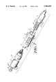
- FIG. 7shows an isometric, exploded view of a further embodiment of the invention with an exemplary barrel and plunger assembly
- FIG. 8shows a side view of the protective cover of the device of FIG. 7;
- FIG. 9shows a cross sectional view of the assembled device of FIG. 7;
- FIG. 10shows a side view of the assembled device of FIG. 7;
- FIG. 11shows a cross sectional view of the assembled device of FIG. 7 with the protective cover in a retracted position
- FIG. 12is a cross sectional view of the assembled device of FIG. 7 with the protective cover in a needle protection position;
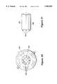
- FIG. 13is an end view of an alternate embodiment of the needle protector mount
- FIG. 14is a cross sectional view of the mount of FIG. 13 taken along line 14--14 of FIG. 13;
- FIG. 15is a cross sectional view of the mount of FIG. 13 taken along line 15--15 of FIG. 13;
- FIG. 16is a side view of a needle subassembly
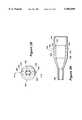
- FIG. 17is an end view of an alternate embodiment of the protective cover
- FIG. 18is a cross sectional view of the protective cover of FIG. 17 taken along line 18--18 of FIG. 17;
- FIG. 19is a side view of the protective cover of FIG. 17;
- FIG. 20is an alternate side view of the protective cover of FIG. 17;
- FIG. 21is a side view of an alternate spring
- FIG. 22is a side view of an alternate embodiment of the needle protector device including the mount of FIGS. 13-15, the needle subassembly of FIG. 16, the protective cover of FIGS. 17-20, and the spring of FIG. 21;
- FIG. 23is a cross sectional view of the needle protector device of FIG. 22 with the protective cover in the needle protection position;
- FIG. 24is a cross sectional view of the needle protector device of FIG. 22 with the protective cover in a retracted position;
- FIG. 25is a cross-sectional, exploded view of a still further embodiment of the present invention.
- FIG. 25Ais an enlarged view of one of the slot-shaped channels of the mount of FIG. 25;
- FIG. 26is a cross-sectional view of the device of FIG. 25 in the assembled, locked position
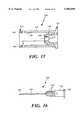
- FIG. 27is a cross-sectional view of the device of FIG. 25 in a retracted position
- FIG. 28is an end view of the protective cover of the device of FIG. 25;
- FIG. 29is a cross-sectional view of the protective cover taken along line A--A of FIG. 28;
- FIG. 30is an end view of a further embodiment of the needle protector device.
- FIG. 31is a partial side view of the protective cover of the device of FIG. 30.
- FIG. 32is a cross-sectional view of a still further embodiment of a mount and needle subassembly adapted for coupling to a protective cover of the type shown in FIG. 25.
- An upper portion 10is a hollow tubular mount that supports a needle 11 at one, lower end 20.
- the other, upper endhas a flange 12, with a notch or slot 13 to accommodate the upper end 41 of a spring 40 in a manner that will be described later.
- This other, upper end of the tubular sleeve 10will, normally, include one of the conventional couplings for a syringe, such as the luer fitting 14 shown in FIG. 3. This has been omitted here, and in other drawings, for simplicity. Other fittings for similar functions can also be accommodated.
- the needle 11is mounted in the center of the base 20 at the lower end of the tubular needle mount 10, in a well known manner.
- the sharp point, or tip, of the needlewill be protected by a cover or sleeve 30.
- This exploded viewshows, quite clearly, typical slots in the needle mount that control the position and function of the protective cover 30 for the needle in a manner that will be illustrated in the other figure and described in more detail in due course.
- These typical slotsinclude an opening 21 for an elongated starting or entrance slot 22 that goes up to a change-over slot 23, that leads to an elongated exit slot 24 that ends in a locking ledge 25 that automatically locks the protective cover 30, with its lower end 31 over the needle.
- the protective cover 30has an opening 31 in its lower end that the needle can extend through when its inner lug 34 is moving through the slots 22, 23, and 24, and the device is in use.
- the other, upper end 32is open and forms the sleeve that fits loosely around the tubular needle mount 10.
- a notch 35may be provided in the upper end 32 of the sleeve 30 to support the lower end 42 of the spring 40, as shown. This spring 40 provides the automatic operation of the protective cover.
- Another, flat spring 33actuates a lug or cam 34, seen in FIGS. 3, 4, and 5, that rides in the slots 21 through 26 for the automatic control of the protective sleeve.
- the spring 40would, in operation, fit loosely over the tubular needle mount 10.
- the upper end clip 41would fit into, and may be secured in the notch or slot 13 of the flange 12.
- the lower end clip 42would fit into the notch or slot 35, as noted earlier, and may also be secured therein.
- FIG. 2shows a plan view of the lower end 20 of the tubular needle mount, seen along the needle 11. This, more clearly, shows the opening 21 for the start of the lug 34, mounted on the underside of the spring 33, through its automatic locking path. This also shows the ledge 25, at the end of the slot 24, that secures the lug or cog 34 and locks the protective cover 30, with its end 31 well over the sharp end of the needle.
- the needlecan be reactivated by rotating the sleeve 30, and moving its cog up the ramp 26 to drop back into the starting slot at 21.
- FIG. 3shows a cross section of the device along the lines 3 3 of FIG. 2.
- Thisshows the protective sleeve 30 with its upper end 32 over the tubular mount 10, its lower end 31 covering and protecting the sharp end of the needle 11, and its cog 34 started in the opening 21.
- the slot 22will guide the cog to the changeover slot 23, and may raise it partially in the process.
- This figurealso shows the flange 12, with the notch or slot 13 to accommodate the upper, outer end clip 41 of the spring 40.
- the spring 40is not shown in this and the subsequent drawings for simplicity and clarity in illustrating the other, most important elements of the safety cover, and their complex functions.
- a typical luer fitting 14is illustrated in this figure. Obviously this--or a similar coupling would be necessary for coupling this safety device to any conventional unit that needs a hypodermic needle, which is the normal function of this device.
- FIG. 4shows another cross section of this device along the lines 4--4 of FIG. 2.
- Thisshows the protective sleeve-or cover 30 drawn to the upper end of the tubular mount 10.
- Thisshows the cog 34, on the flat spring 33 of the sleeve 30 in the cross-over slot 23, and the needle fully exposed.
- similar elementsare similarly numbered.
- the luer fitting 14is, again, omitted for simplicity in this and the rest of these drawings.
- FIG. 4Ais a top view of the tubular mount 10 for mounting the needle 11, normal to the lines 4--4 of FIG. 2, and is added to illustrate another variation of the slots 21 through 26.
- Thisis the version that is, actually, used in the drawings 3, 4, and 5.
- To thishas been added a notch 27 along the cross-over 23. This would hold the lug 34 against the pressures of the spring and would allow the protective cover 30 to be held with the needle exposed, if necessary, while it is being inserted or used. Subsequent movement or use of the cover 30 would complete the cycle, along the path of the lug 34, to the slot 24 and to the ledge 25, to lock the protective cover 30 in its safe position.
- This figurealso shows more depth to the cross-over 23.
- this cross-overcould extend from near the top of the slots to near the lower end of the mount. This could provide the essential, automatic safety locking of the sleeve with a minimal penetration of the needle, which might be advisable in many cases.
- FIG. 5is another cross section of the device, along the lines 5--5 of FIG. 2, and this shows the protective cover at the end of its cycle, with the lug 34 of the protective cover system locked against the ledge 25, and the end of the cover 31 well over the tip of the needle 11.
- FIG. 6is another plan view of the bottom 20 with a variation of the needle holder, again in line with the needle 11. This shows an additional slot 21A, a ledge 25A, and a resetting slope 26A to accommodate an additional lug, not shown, to double the strength and the safety of the automatic locking function. Additional combinations of slots and lugs could, obviously, be added for additional strength and safety.
- the deviceIn operation, the device would normally be assembled with the elements of FIG. 1 compressed to the profile of FIG. 3.
- the spring 40would fit loosely over the tubular needle mount 10, with its upper end 41 seated in the notch 13 of the mount.
- the lower end of the spring 42is secured into the slot 35 of the protective cover, to hold the cog 34, mounted in the cover, in line with and against the ledge 25 so that the protective cover cannot be pushed back to expose the sharp end of the needle, whether it has been used or not.
- the needle mount 10can be coupled to an appropriate syringe, or other device at its fitting 14.
- the cover or sleeve 30can then be rotated--in this case clockwise--to move the cam 34 up the slope 26 to drop into the opening 21 at the start of the slot 22.
- the only way the cam can get back from its starting position 21is to slide along the slots 22, 23, and 24 to be lifted and dropped back into the locking position at 25.
- the springexerts a rotary pressure on the cover to urge the cam back towards its exit slot 24, and its locking position at 25.
- the springalso exerts an axial pressure on the cover to hold it in position over the sharp end of the needle until it is being used.
- the springis then compressed axially to expose the needle for use, while moving the cam along the slots 22 and 23. Then the cam can only follow the slot 24 to return the cam, automatically, by the combined rotary and axial pressures of the spring, to its safe, locking position over the ledge 25, where the sharp end of the now used needle is automatically and permanently protected against accidental penetration of anything or anybody.
- the springhere, has this double function, and insures the automatic operation of the safety protective cover.
- the springmay be made of any springy material, from metal to plastic, and may be of any suitable, functional shape. Actually, the spring 40 may be molded as part of the sleeve 30, when suitable materials are chosen.
- the materials chosenwould presumably be of plastic. Both the protective cover, with or without the spring, and the tubular mount for the needle would, obviously, be molded for mass production and cost effectiveness. While the safety of medical workers is of prime importance, the cost of providing safety should be reasonable.
- the object of this inventionis to provide the best possible, and almost fool-proof protection, at a minimal cost.
- the mount 10 that physically supports the needlewhich is the essential element of this device, is standard, and similar to many standard needle holders, that couple a needle to a luer, or other fitting, for its ultimate use. However, this unit may be slightly longer to accommodate the motion of the protective sleeve over the needle and mount.
- the length of the sleeve, and the mountwill vary with the length and size of the needle, which will vary according to its many uses.
- the size and shape of the devicewill vary, along with the ultimate use. This will, again, be a function of the size, and length of the needle. The smallest possible would, of course, be most desirable.
- a solid, thin cap over the base 20, at the lower end of the mountwould be very easy to attach, and desirable for locking the lug in both directions. This would prevent the sleeve from being pulled off the needle mount, as well as from being pushed in to expose the needle, which would virtually eliminate exposure of the needle in any manner.
- a secondary means for raising the spring 33would be needed to fit the lug 34 in either the starting slot or the locking ledge. This could also avoid the need for, or use of the slope 26, which could be eliminated, to avoid the accidental rotation of the sleeve to arm the device.
- the protective sleeve 30, as well as most of the rest of the device,would be of plastic for ease of manufacture.
- the sleeveshould be as small as practical, and quite transparent to allow the needle to be seen and controlled.
- the opening at 31may be the full size of the sleeve, or may be just large enough, as shown, for the needle to fit through.
- a further embodiment of the inventionis shown to include a protective cover, or sleeve 50 which fits inside a hollow, tubular mount 60.
- the protective cover 50has an opening 51 at its lower end of a diameter suitable for permitting a needle 55 to extend therethrough during use.
- the diameter of the upper end 52 of the cover 50is smaller than that of the mount 60 into which the cover extends.
- the protective cover 50includes a pair of notches 55, 56 at the upper end 52 which are spaced to provide a cantilevered tab 57 therebetween.
- An upper end of the tab 57has a lug 58 protruding therefrom, as shown also in FIG. 8.
- the cantilevered arrangement of tab 57provides the tab with a resiliency which is advantageous during assembly of the device, as will be described.
- a second, like tab 74 and a second pair of notches 87, 88are provided in the upper end of the cover 50 at opposing locations with respect to the tab 57 and notches 55, 56, respectively.
- the second tab 74has a lug 75 protruding therefrom, like lug 58.
- Each of the lugs 58, 75has a tapered edge 65, 76, respectively, which further facilitate assembly of the device, and a flat edge 69, 77, as shown.
- a spring 62provides automatic operation of the protective cover 50 in response to axial and torsional forces applied during operation, as will be described. Suffice it here to say that the spring 62 is coupled between the protective cover 50 and the mount 60 with a lower end of the spring 62 attached to the cover 50 and an upper end attached to the mount 60. Specifically, the lower end of the spring has a hook portion which extends through a loop 59 on the upper end 52 of the cover 50.
- the hollow, tubular mount 60has an open lower end 61 for receiving the upper end 52 of the protective cover 50 and an upper end 63 coupled to a hub 66. More particularly, the upper end 63 of the mount 60 has an opening for receiving the hub 66, as can be seen in the cross-sectional views of FIGS. 11 and 12.
- the hub 66supports the needle 55 at a lower end and has a coupling, or fitting, such as a luer fitting, at an upper end for mating with a conventional syringe barrel and plunger assembly.
- One exemplary assembly 80is shown in FIG. 7 to include a barrel 81 and plunger 82.
- Various means for fastening the hub 66 to the mount 60are suitable, such as sonic welding.
- Both the barrel and plunger assembly 80, as well as the hub and needle assembly 66may be conventional, commercially available assemblies.
- the spring 62is secured to the upper end of the mount 60 by locating the upper end of the spring 62 in a hole 64 in the upper end 63 of the mount 60 (see FIGS. 11 and 12).
- the tubular mount 60has two apertures 70, 71 and a pair of slots 72, 73, each one corresponding to one of the apertures 70, 71, respectively, and being spaced therefrom. Slots 72, 73 facilitate assembly of the device, as will be described.
- Each of apertures 70, 71has a width labelled "w”, a length labelled "l”, and permits the protective cover 50 to be in a needle protection position, an armed position, or in one of a plurality of retracted positions during use of the device when the needle 55 is exposed.
- the lug 58engages the aperture 70 and is moveable within the constraints of the aperture 70 to provide the cover 50 in the needle protection position, the armed position, or a retracted position. That is, the lug 58 protrudes through the aperture 70, slightly beyond the inner diameter of the mount 60, so that the edges, or walls of the aperture 70 restrict the movement of the lug 58 and cover 50. However, preferably, the lug 58 does not protrude beyond the outer diameter of the mount 60 in order to prevent potential undesirable interference with actuation of the device.
- the needle protection position of the cover 50corresponds to the lug 58 being located in a first, entrance position 67 of the aperture 70.
- the armed positioncorresponds to the lug 58 being in a second, armed position 68 of the aperture 70.
- the cover 50is in a retracted position, the lug 58 is located above the entrance and armed positions 67, 68 and toward the upper end of the mount 60 between an entrance wall 85 and an exit wall 86 of the aperture 70.
- the entrance and armed positions 67, 68 of the mount aperture 70are radially spaced by an angled portion 78 of the mount 60. While the operation of the device is described with respect to exemplary lug 58 and aperture 70, it is understood that aperture 71 has like features for engaging corresponding lug 74.
- the mount 60 and the protective cover 50may be comprised of any material having suitable strength and other desired characteristics, such as plastic. Additionally, the mount 60 and cover 50 may be manufactured by any conventional technique, such as injection molding. Preferably, the cover 50, and at least the lower end 51 thereof, is made from a transparent material so that the tip of the needle 55 is visible in order to facilitate proper insertion into a needle receiving surface, such as a patient's arm.
- Spring 62may be made of any suitable material providing a spring characteristic, such as metal or plastic. It should be understood that the selected materials and method of manufacturing the components of the device will vary in accordance with, inter alia, application requirements and cost considerations.
- mount 60is fastened to the hub 66 as noted above, such as by a sonic welding process.
- the upper end of the spring 62is positioned in the hole 64 at the upper end 63 of the mount 60 and the lower end of the spring 62 is attached to the cover 50 and specifically, to the loop 59.
- the cover 50is guided into the larger diameter mount 60 with tabs 57, 74 aligned with corresponding slots 72, 73.
- the cantilevered tabs 57, 74are deflected slightly inward toward the inside of the mount 60. This rotation of the cover 50 is facilitated by the tapered edges 65, 76 of the lugs 58, 75, respectively.
- the cover 50is prevented from rotating counterclockwise due to the flat edge 69 of the lug 58 contacting the side of the entrance position 67 of the mount 60 adjacent to the slot 72.
- the assembled deviceis shown in FIG. 10 with the lug 58 positioned in the entrance position 67 of the aperture 70.
- the protective cover 50extends over the tip of the needle 55 and cannot be pushed straight back to expose the needle 55 since the back wall of the entrance position 67 prevents such movement of the lug 58.
- the spring 62With the cover 50 disposed in this needle protection position, the spring 62 is in a partially compressed state. Additionally, the spring 62 is subjected to a slight rotary torque, or torsional force, as a result of the rotation of the spring 62 as the cover 50 was rotated to move the lug 58 from the slot 72 to the entrance position 67.
- the hub 66When use of the needle 55 is desired, the hub 66 is coupled to a conventional syringe barrel and plunger assembly, such as the exemplary assembly 80 shown in FIG. 7.
- the upper end of the hub 66has a fitting, such as a luer fitting, for this purpose.
- the devicemay be armed, or cocked, in preparation for use by rotating the cover 50 clockwise which causes the lug 58 to move along the angled portion 78 of the mount 60 that separates the entrance position 67 from the armed position 68.
- an audible clickoccurs, indicating to the user that the device is armed and ready for use.
- an additional rotary torqueis exerted on the spring 62 which, upon actuation of the device, urges the lug 58 back to the entrance position 67.
- the torsional and compressive forces exerted on the spring 62urge the protective cover 50 back to the needle protection position in which the lug 58 is located in the entrance position 67.
- the protective cover 50automatically moves to the needle protection position in which the needle tip is covered.
- the rotary torque on the spring 62causes the cover 50 to move radially, rotating counterclockwise so that the lug 58 contacts the exit wall 86 and the compressive force on the spring 62 causes the cover 50 to move outward from the mount 60 to the needle protection position shown in FIGS. 10 and 12. It is noted that once the lug 58 has returned to the entrance position 67, the device may be reactivated by re-arming the device for further use.
- the devicecan be re-armed by rotating the cover 50 clockwise which causes the lug 58 to move along the angled portion 78 of the mount 60 separating the entrance position 67 and the armed position 68, in the manner described above.
- the dimensions of the apertures 70, 71may be varied in accordance with a particular application. For example, a longer needle 55 may require that the aperture 70 have a greater length "l" to permit a desired exposure of the needle 55. Additionally other device dimensions, such as those of the mount 60 and the cover 50, may be readily varied as required in a particular application.
- FIGS. 7-12While the embodiment of FIGS. 7-12 is shown to have two opposingly disposed tabs 57, 74, apertures 70, 71, and slots 72, 73, it should be appreciated that a single tab, aperture, and slot arrangement may be suitable in certain applications.
- the needle protector arrangements described hereinare useable with conventional syringe barrel/plunger assemblies, such as the exemplary assembly 80 of FIG. 7, so that inventory of such assemblies need not be discarded and replaced in order to use the described devices. Additionally, by modifying the mount 10 to provide slots 22-26 (FIGS. 1-6) and the mount 60 to provide apertures 70, 71 (FIGS. 7-12), the advantages of the present needle protector embodiments are achieved without requiring additional parts.
- FIG. 13is an end view of the mount 100.
- FIG. 14is a cross-sectional side view of the mount 100 taken along line 14--14 of FIG. 13 and
- FIG. 15is an alternate cross-sectional side view of the mount 100 taken along line 15--15 of FIG. 13.
- the mount 100is substantially cylindrical, or tubular in shape and has an upper end 102 and an open lower end 104.
- An interior channel 106extends from the upper end 102 of the mount to terminate at a terminal end, or edge 108.
- the channel 106is tapered such that the diameter of the channel 106 at the terminal edge 108 is reduced relative to the diameter of the channel 106 adjacent the upper end 102 of the mount 100.
- a needle subassemblysuch as that shown in FIG. 16, is coupled to the mount 100 by insertion into the tapered channel 106.
- a needle subassembly 120includes a hub 122 having a luer fitting 124 at a first end and a needle 126 extending from a second end to terminate at a tip 128, as shown.
- the luer fitting 124is adapted for connection to a conventional syringe barrel and plunger assembly.
- the hub 122has a plurality of ribs 130 extending axially with respect to the needle 126 along the exterior surface of the hub 122.
- the hub 122is comprised of a plastic material having some resiliency.
- the smallest inner diameter of the mount channel 106, adjacent the terminal edge 108,is slightly smaller than the outer diameter of the hub with the ribs 130.
- the needle subassembly 120may be a conventional, commercially available assembly, as is available from Becton Dickinson & Co. of Rutherford, N.J.
- the needle 126is one inch long. Use of a one inch needle is advantageous, as compared to use of a longer needle, since the shorter needle is less susceptible to bending and thus, is stronger.
- the mount 100has a plurality of stops 110 protruding from the interior walls of the channel 106 into the diameter of the channel 106. Two such stops 110 are visible in the view of FIG. 14 and one stop 110 is visible in the view of FIG. 15.
- the hub ribs 130are aligned with the mount 100 such that the ribs are disposed between the stops 110. With this arrangement, the stops 110 prevent the needle subassembly 120 from rotating relative to the mount 100 once the subassembly 120 is press fit into the mount 100.
- a spring receiving aperture 140(FIGS. 13 and 14) is disposed in the upper end 102 of the mount 100 between the mount exterior wall 142 and the channel 106, as shown. In assembly, the spring receiving aperture 140 receives one end of a spring, such as the spring 144 shown in FIG. 21 and discussed below.
- the mount 100includes two apertures 152, 154 (only one of which can be seen in the views of FIGS. 14 and 15) and a pair of assembly ramps 156, 158 (FIGS. 13 and 15), each one corresponding to one of the apertures 152, 154.
- Each of apertures 152, 154is substantially identical to like apertures 70, 71 described above in conjunction with the embodiment of FIGS. 7-12.
- each aperturehas an entrance position 160, an armed position 162 radially spaced from the entrance position by an angled protrusion 168, and an elongated portion 170 extending toward the upper end 102 of the mount between an entrance wall 164 and an exit wall 166 of the aperture.
- Assembly ramps 156, 158are tapered, or angled portions of the inner wall 143 of the mount 100 extending from the lower end 104 of the mount 100 toward the respective aperture 152, 154, as shown in FIG. 15.
- the taper of the ramps 156, 158is such that the wall is thinnest at the portion of the ramp adjacent to the lower end 104 of the mount 100 and is thickest at the portion of the ramp adjacent to the respective aperture 152, 154.
- the assembly ramps 156, 158facilitate attachment of the protective cover, such as cover 180 of FIGS. 17-20, to the mount 100 by gradually increasing the deflection of the cover lugs until the lugs enter the respective aperture 152, 154, as described below.
- the mount 100includes an alignment groove 112 shown in FIGS. 13 and 14 extending axially along wall 142. Groove 112 facilitates alignment of the mount 100 during manual or automated assembly of a needle protector including the mount 100 by providing a reference relative to which the mount 100 can be aligned.
- FIG. 17is an end view of the cover 180
- FIG. 18is a cross-sectional view of the cover taken along line 18--18 of FIG. 17
- FIGS. 19 and 20are alternate side views of the cover 180 showing its various features.
- the protective cover 180is substantially cylindrical and has an upper end 182 of an outer diameter slightly smaller than the inner diameter of the lower end 104 of the mount 100, permitting the upper end 182 of the cover 180 to be received within the lower end 104 of the mount 100.
- a lower end 184 of the protective cover 180has a reduced diameter relative to the diameter of the upper end 182, so as to prevent a finger from being inserted through the open lower end 184 to contact the needle 126.
- the protective cover 180includes a first pair of notches 192, 194 (FIG. 19) at the upper end 182 which are spaced to provide a cantilevered tab 186 therebetween.
- An upper end of the tab 186has a lug 190 protruding therefrom.
- the cantilevered arrangement of tab 186provides the tab with a resiliency which is advantageous during assembly of the device, as will be described.
- the protective cover 180includes a second pair of notches (not shown) identical to notches 192, 194 which provide a second tab 196 cantilevered therebetween with a lug 200 protruding therefrom.
- the second tab 196is positioned 180° from the first tab 186.
- the first and second lugs 190, 200are adapted for engaging the first and second apertures 152, 154 of the mount 100 in assembly, respectively. As noted above with respect to the embodiment of FIGS. 7-12, in some applications, a single cover lug and mount aperture arrangement may be suitable.
- the mount 100 and the protective cover 180may be comprised of any material having suitable strength and other desired characteristics, such as plastic. Additionally, the mount 100 and cover 180 may be manufactured by any conventional technique, such as injection molding. Preferably however, the cover 180 is made from a transparent material so that the tip of the needle 126 is visible in order to facilitate insertion into a needle receiving surface, such as a patient's arm.
- the mount 100 and cover 180be comprised of different materials in order to reduce any sticking therebetween over time.
- the mount 100is comprised of the copolymer styrene-acrylonitrile (SAN) from Monsanto of St. Louis, Mo. and the protective cover 180 is comprised of a polycarbonate from GE Plastics of Pittsfield, Mass.
- SANcopolymer styrene-acrylonitrile
- Additional features of the protective cover 180include an alignment groove 204 in the exterior surface of the mount 100, as shown in FIGS. 18 and 20.
- the alignment groove 204facilitates assembly of the device by providing a reference feature with which the cover 180 can be aligned, or oriented during assembly.
- the alignment groove 204permits ready alignment of the cover 180, whether assembly is manual or automated, and can be used in conjunction with the mount alignment groove 112 (FIGS. 13 and 14) to facilitate alignment of the mount 100 relative to the protective cover 180 as the lugs 190, 200 of the cover 180 are directed along the respective assembly ramps 156, 158 of the mount.
- a spring receiving aperture 206is disposed in a wall of the protective cover 180, as shown in FIGS. 17 and 18. Specifically, the spring receiving aperture 206 is positioned at the upper end 182 of the protective cover 180 for receiving an end of a spring, such as spring 144 shown in FIG. 21.
- the tapered inner wall portion 210adjacent to the reduced diameter lower end 184 of the cover 180.
- the wall portion 210is tapered such that the wall is thickest at the portion distal from the lower end 184 and is thinnest at the portion adjacent to the end 184, as shown.
- the purpose of the tapered wall portion 210is to prevent the needle 126 from gouging the wall of the cover 180 in instances where component tolerances are in a worst case condition. That is, in instances where the inner wall diameter of the mount 100 is at the high end of its specified tolerance range and the outer wall diameter of the protective cover 180 is at the low end of its specified tolerance range, the angled wall portion 210 prevents the needle tip 128 from gouging the cover wall.
- Mount apertures 152, 154permit the protective cover 180 to be in a needle protection position, an armed position, or in one of a plurality of retracted positions to expose the needle 126 during use of the device.
- the needle protection position of the cover 180corresponds to the lugs of 190, 200 the cover 180 being located in the entrance position 160 of the respective aperture 152, 154.
- the armed positioncorresponds to the lugs 190, 200 being in the armed position 162 of the respective aperture 152, 154.
- the lugs 190, 200are located in the respective aperture portion 170, above the entrance and armed positions 160, 162 and toward the upper end 102 of the mount 100 between the entrance wall 164 and the exit wall 166 of the respective aperture 152, 154.
- an alternate spring 144is shown to include a pair of extensions 146, 148, extending axially from opposite ends thereof.
- the extensions 146, 148are adapted for engaging the spring receiving apertures 140, 206 of the mount 100 and, the protective cover 180, respectively. Since the spring 144 has a symmetrical construction, issues regarding orientation of the spring during assembly are advantageously avoided.
- Spring 144may be made of any suitable material providing a desired spring constant, such as metal or plastic.
- FIGS. 22-24an alternate needle protector device 220 is shown to include the mount 100 of FIGS. 13-15, the needle subassembly 120 of FIG. 16, the protective cover 180 of FIGS. 17-20 and the spring 144 of FIG. 21.
- FIG. 22is a side view of the device 220 with the cover 180 in the needle protection position.
- the lugs 190, 200are in the entrance position 160 of the respective aperture 152, 154, as shown for lug 190 in aperture 152.
- FIG. 23 and FIG. 24is a cross-sectional view of the needle protector device 220 with the protective cover 180 in a retracted position, thereby exposing the needle 126 through the reduced diameter lower end 184 of the cover 180.
- the spring 144is inserted into the lower end 104 of the mount 100 such that one of the spring extensions 146, 148 extends into the spring receiving aperture 140 at the upper end 102 of the mount, as shown in FIG. 24. With the spring 144 thus positioned, the other spring extension 146, 148 is aligned with the spring receiving aperture 206 of the protective cover 180.
- the mount 100 and the cover 180are rotated by a multiple of 180° relative to one another to impart a torsional bias on the spring 144.
- the mount 100 and cover 180are rotated relative to one another by either 180° or 360°. This process can be readily performed with a simple fixture. Having thus biased the spring 144, the cover 180 is inserted into the mount 100.
- the cover lugs 190, 200are aligned with a respective assembly ramp 156, 158, the upper end 182 of the cover 180 is inserted into the open lower end 104 of the mount 100. Alignment of the cover 180 and the mount 100 is facilitated by the alignment groove 204 on the cover 180 and the alignment groove 112 on the mount 100. As the cover 180 is urged inside the mount 100, the spring 144 is subjected to a compressional force. The lugs 190, 200 of the cover 180 are deflected inward as they ride along the respective ramp 156, 158, as is permitted by their cantilevered construction. The entrance position 160 of each aperture 152, 154 is located axially adjacent to the respective ramp 156, 158.
- the lugs 190, 200overcome the respective ramp 156, 158 and enter the entrance position 160 of the respective aperture 152, 154. Having entered the entrance position 160 of the respective aperture 152, 154, the lugs 190, 200 return to their initial non-deflected positions, thereby causing the lugs 190, 200 to be captured within the respective aperture 152, 154, as shown in the views of FIGS. 22 and 23.
- the cover 180is prevented from separating from the mount 100, since the lugs 190, 200 are captured in respective aperture 152, 154.
- the spring 144is biased both in torsion and compression once the mount 100 and cover 180 are coupled together in the abovedescribed manner.
- the needle subassembly 110is inserted into the mount 100 from the upper end 102 thereof.
- the ribs 130 of the needle subassembly 120are aligned with the interior channel 106 of the mount 100 so as to be in axial alignment with regions of the interior channel 106 between the protrusions 110. With the needle subassembly 120 and the mount 100 thus aligned, the subassembly 120 is urged into the mount 100.
- the needle protector device 220is suitable for either manual or automated assembly.
- the operation of the device 220 thus assembledis substantially identical to the operation of the needle protector embodiment of FIGS. 7-12. That is, when use of the device 220 is desired, the luer fitting 124 of the hub 122 is coupled to a conventional syringe barrel and plunger assembly, such as the illustrative assembly 80 shown in FIG. 7. The device 220 is then armed by rotating the cover 180 clockwise causing the lugs 190, 200 to ride along the angled portions 168 of the respective aperture 152, 154. As the lugs 190, 200 clear the respective angled portion 168, an audible click occurs, indicating to the user that the device 220 is armed and ready for use.
- Actuation of the device 220 by pushing the cover 180 against a needle receiving surfaceforces the cover 180 further inside the mount 100, as shown in FIG. 24.
- the lugs 190, 200are positioned in portion 170 of the respective aperture 152, 154.
- the torsional and compressive forces exerted on the spring 144 during assemblycause the cover 180 to be automatically urged back over the needle tip and thus, cause the lugs 190, 200 to be automatically urged to return to the entrance position 160 of the respective aperture 152, 154.
- the device 220can be re-activated or re-armed for further use.
- the features of the needle protector 220 of FIGS. 22-24permit a simple, effective, and relatively inexpensive manner of assembly.
- the press fit attachment of the needle subassembly 120 to the mount 100provides an effective way of securely attaching the subassembly 120 and mount 100, without requiring the hub 122 to be sonically welded or solvent bonded to the mount 100.
- the spring 144simplifies manufacture of the device 220 by its symmetrical construction, thereby eliminating orientation issues.
- the axial spring extensions 146, 148are further advantageous in their simplicity of engagement with the mount 100 and cover 180. Furthermore, this axial spring extension arrangement is conducive to biasing the spring 144 in torsion prior to attaching the cover 180 to the mount 100.
- the alignment grooves 112, 204 of the mount 100 and cover 180, respectively, as well as the assembly ramps 156, 158 of the mount 100further enhance the ease with which the device 220 is assembled, as described above.
- FIGS. 25 through 29A still further embodiment of the needle protector device is shown in FIGS. 25 through 29.
- the device 300comprises a mount 302, a protective cover 304, a needle subassembly 306, and a compression spring 308.
- the needle subassembly 306may be like the needle subassembly 120 discussed above.
- the mount 302is substantially cylindrical or tubular in shape and has an upper end 310 and an open lower end 312.
- An interior collar 314 concentric with an exterior wall 316 of the mount 302extends from the upper end of the mount to terminate at a terminal end or edge 318.
- At least a portion 320 of the collar 314is tapered such that the diameter of the collar at the terminal edge 318 is reduced relative to the diameter of the collar adjacent the upper end 310 of the mount 302.
- the needle subassembly 306comprising a hub 322 and a needle 323, is coupled to the mount 302 by insertion into the tapered collar 314.
- the smallest inner diameter of the collar, adjacent the terminal edge 318,is slightly smaller than the outer diameter of the hub 322 of the needle subassembly.
- the stopsprevent the needle subassembly 306 from rotating relative to the mount 302 once the subassembly is press fit into the mount. In this manner, the needle subassembly becomes fly attached to the mount, and the device can be actuated, discussed further below, by grasping a conventional syringe barrel and plunger assembly attached to the needle subassembly, rather than by grasping the mount, thereby maintaining the user's hand safely farther away from the region of the needle.
- the mount 302includes two slot-shaped channels 330 (only one of which can be seen in FIGS. 25-27). An enlarged view of one of the slot-shaped channels 330 is shown in FIG. 25A.
- Each channel 330has an entrance portion 332 and an elongated portion 334 which are joined by a substantial bend 336.
- the entrance position 332includes a detent 356 adjacent to the lower end 312 of the mount 302.
- the elongated portion 334extends from the bend 336 toward the upper end 310 of the mount 302 at an angle to the longitudinal axis of the mount. The angle is typically approximately 3°, although the exact angle is not critical to operation of the device, and the optimum angle can be readily determined by those skilled in the art.
- two channels 330are provided, spaced 180° apart circumferentially. However, one or any other number of channels can be provided if desired.
- the protective cover 304is substantially cylindrical and has an upper end 340 of an outer diameter slightly smaller than the inner diameter of the lower end 312 of the mount 302, permitting the upper end of the cover to be telescopically received within the lower end of the mount.
- a lower end 342 of the protective coverhas a reduced diameter relative to the diameter of the upper end 340, to prevent a finger from being inserted through the open lower end to contact the needle 323.
- the protective cover 304includes two U-shaped cut out regions 344 in an intermediate portion 346 to provide two cantilevered tabs 348.
- An upper end of each tabhas a lug 350 protruding radially outwardly therefrom.
- the cantilevered arrangement of the tabs 348provides the tabs with a resiliency which is advantageous during assembly of the device, as will be described.
- the tabsare positioned 180° apart circumferentially.
- the two lugs 350are adapted for engaging the two channels 330 of the mount, respectively. As noted above with respect to the channels of the mount, one or any other number of cover lugs may be provided, the location and number of lugs corresponding with the location and number of channels.
- the lower end 312 of the mount 302includes a chamfer 305 around its inner circumference.
- the chamferfacilitates attachment of the protective cover 304 to the mount 302 by gradually increasing the deflection of the cover tabs 348 until the lugs 350 enter the respective channels 330, as described below.
- the angle of the chamferis slightly greater at locations aligned with the channel entrance portions 332 to define a pair of assembly ramps 352.
- the differently angled rampsprovide a tactile locator for aligning the lugs 350 with the entrance portion 332.
- a detent(such as the alignment groove 112 illustrated in FIG.
- the lower end of the mountmay be provided with an annular, outwardly extending lip 354 as well, which may serve as a finger stop to discourage placement of the fingers on the protective cover.
- An annular spring-receiving recess 360is disposed in the upper end 310 of the mount 302 between the mount exterior wall 316 and the collar 314.
- An annular spring-receiving shelf 362is formed on the interior of a wall of the protective cover 304. The annular shelf opposes the annular spring-receiving recess 360 in the mount. In this manner, the compression spring 308 can be compressed between opposing faces of the shelf 362 and the recess 360, the collar 314 serving to center the spring 308.
- the springmay comprise any suitable compression spring having a desired spring constant and may be formed of a variety of materials, such as metals or plastics.
- the spring 308is inserted into the lower end of the mount 302 such that one end of the spring extends into the annular spring-receiving recess 360 at the upper end of the mount.
- the other end of the springis placed against the spring-receiving shelf 362 of the protective cover 304.
- the cover lugs 350are aligned visually and/or tactiley with a respective assembly ramp 352, and the upper end 340 of the cover 304 is inserted into the open lower end 312 of the mount 302. As the cover 304 is urged inside the mount 302, the spring 308 is compressed.
- the lugs 350 of the coverare deflected inwardly as they ride along and finally over the respective ramps 352, as is permitted by their resilient cantilevered construction, to enter the entrance portion 332 of the respective channels 330.
- the tabs 348then return to their initial non-deflected positions, thereby causing the lugs 350 to be captured within the respective channel 330 and preventing separation of the cover 304 and the mount 302.
- the spring 308is biased solely in compression once the mount and cover are coupled together in the above-described manner.
- the needle subassembly 306is inserted into the mount from the upper end thereof.
- the ribs 326 of the needle subassemblyare aligned within the collar 314 of the mount 302 between the stops 324. With the needle subassembly 306 and the mount 302 thus aligned, the subassembly 306 is urged into the mount.
- the needle protector device 300is suitable for either manual or automated assembly. When use of the device is desired, the luer fitting 366 of the hub 322 is coupled to a conventional syringe barrel and plunger assembly, such as the illustrative assembly 80 shown in FIG. 7.
- the configuration of the channels 330 in the mount 302permits the protective cover 304 to be in either a locked, needle protection position (shown in FIG. 26) or in one of a plurality of retracted positions to expose the needle during use of the device (shown in FIG. 27) and obviates the need for an armed position and the attendant risks of rotating the device into the armed position.
- the locked, needle-protection position of the cover 304corresponds to the lugs 350 of the cover being located in the entrance portion 332 of the respective channel 330 and, more specifically, being located in the detent 356 of the entrance portion 332.
- the lugs 350must be moved out of the entrance portion 332 by pushing the mount 302 with respect to the cover 304 against the biasing of the compression spring 308 in order to move the lugs out of the respective detent 356 and further, by rotating the cover 304 with respect to the mount 302 past the substantial bend 336 and into the elongated portion 334.
- the lugs 350preferably have a rounded corner (best seen in FIGS. 25 and 26) to prevent binding within the bend 336.
- the channel portion 338 between the entrance portion 332 and the bend 336is at a predetermined angle which is selected in order to prevent movement of the lug 350 into the elongated portion 334 without a deliberate rotation of the cover 304 with respect to the mount 302.
- the portion 338is at approximately 18° relative to the lateral axis of the device.
- the needle 323cannot be exposed by merely pushing the mount 302 with respect to the cover 304 against the biasing of the compression spring 308.
- the pushing actionis sufficient to retract the cover 304 from the needle 323 as the lugs 350 travel along the respective elongated portions 334 toward the upper end 310 of the mount 302.
- the deviceIn operation of the assembled device 300, it is not necessary to first arm the device, as noted above. Rather, the device is directly actuated by simultaneously pushing the device against a needle-receiving surface 370 and rotating the mount 302 with respect to the cover 304, as best indicated in FIG. 27. Additionally, as noted above, the user can provide this actuation by grasping the barrel and plunger assembly, rather than the mount. The rotation unlocks the device and the pushing action moves the cover 304 further inside the mount 302, with the lugs 350 following the angled path of the elongated portion 334 of the channel 330. In the fully retracted cover position, the lugs are positioned at the far end of the respective channel.
- the compressive force exerted by the spring 308 and the slight torsional bias imparted to the spring during the unlockingcause the cover 304 to be automatically urged back over the needle tip and cause the lugs 350 to return to the entrance portion 332 of the respective channel 330 following the angled path of the slotted channel.
- a needlemust be inserted through a latex plug in an end of a drug vial.
- the protective cover 304'is provided with a plurality of suitably configured sharp points or prongs 380 on the lower end 342'. In use, the prongs bite into the plug in the vial, thereby preventing the device from slipping when the mount is rotated with respect to the cover.
- the mount and the protective covermay be comprised of any material having suitable strength and other desired characteristics, such as plastic. Additionally, the mount and cover may be manufactured by any conventional technique, such as injection molding. Preferably, the cover is made from a transparent material so that the tip of the needle is visible in order to facilitate insertion into a needle receiving surface, such as a patient's arm or a vial or ampule. It is further preferable that the mount and cover be comprised of different materials in order to reduce any sticking therebetween over time; for example, the mount may be comprised of the copolymer styrene-acrylonitrile (SAN) from Monsanto of St. Louis, Mo., and the protective cover of a polycarbonate from GE Plastics of Pittsfield, Mass.
- SANcopolymer styrene-acrylonitrile
- the features of the needle protector device 300 of FIGS. 25 through 29provide safer actuation and permit a simple, effective, and relatively inexpensive manner of assembly.
- the springdoes not require prebiasing in torsion, simplifying both assembly and operation.
- the deviceis safer to operate, since it does not require arming by rotating the cover with respect to the mount which requires placing the hand close to the opening through which the needle extends.
- the deviceis simpler to operate, in that it needs only to be placed against a needle-receiving surface before actuating the device.
- the deviceis safer in that actuation requires simultaneously pushing the device against the needle-receiving surface and turning the mount with respect to the cover, thereby reducing the likelihood of inadvertent actuation.
- the safety features of the deviceare further enhanced by the automatic return to the locked position upon removal from the needle-receiving surface.
- FIG. 32an alternate embodiment of a mount 400 for the needle protector device is shown.
- the mount 400is intended for use with a protective cover (like cover 304 of FIG. 25) and a compression spring (like spring 308 of FIG. 25).
- the mount 304is substantially cylindrical and has an upper end 404 and an apertured lower end 408.
- the mount 400includes two slots, or channels 402 (only one of which can be seen in view of FIG. 32). Like the channel 330 (FIG. 25), channel 402 has an entrance position 406 and an elongated portion 418 which are joined by a substantial bend 428.
- the slot 402is adapted for receiving a cantilevered tab 348 of the protective cover 304 (FIG. 25) in the manner described above.
- An interior collar 410 of the mount 304is concentric with an exterior wall 412 and extends from the upper end 404 to terminate at a terminal edge 414. At least a portion of the collar 410 is tapered such that the diameter of the collar at the terminal edge 414 is reduced relative to the diameter of the collar adjacent to the upper end 404.
- the interior of the collar 410has at least one thread 416, as shown. In the illustrative embodiment, the thread 416 is a male thread.
- the needle subassembly 420may be like the subassembly 120 (FIG. 16) or 306 (FIG. 25) discussed above. To this end, the needle subassembly 420 includes a hub 422 from which a needle 424 extends, as shown.
- a plurality of ribs 426project outwardly from the hub 422 and are spaced by slots, or grooves 430.
- the outer diameter of the needle subassembly 420 as defined by the ribs 426is slightly larger than at least a portion of the tapered collar 410 adjacent to the collar's terminal edge 414.
- a conventional Luer fitting 432is provided at an upper end of the needle hub 422 for coupling to a source of intravenous fluid, such as to a conventional barrel and plunger arrangement.
- the needle subassembly 420is attached to the mount 400 by inserting the hub 422 into the channel defined by the collar 410.
- the needle subassembly 420is pushed into the channel of the collar 410 to a predetermined extent. Thereafter, the subassembly 420 is rotated relative to the collar 410.
- the rotationcauses the male screw thread 416 on the interior to the collar 410 to bite into the needle subassembly hub 422. More particularly, the thread 416 carves a slight groove into the ribs 426 of the hub 422. In this way, the needle subassembly 420 is maintained in fixed attachment to the mount 400 and is prevented from being readily removed.
Landscapes
- Health & Medical Sciences (AREA)
- Engineering & Computer Science (AREA)
- Heart & Thoracic Surgery (AREA)
- Vascular Medicine (AREA)
- Anesthesiology (AREA)
- Biomedical Technology (AREA)
- Environmental & Geological Engineering (AREA)
- Hematology (AREA)
- Life Sciences & Earth Sciences (AREA)
- Animal Behavior & Ethology (AREA)
- General Health & Medical Sciences (AREA)
- Public Health (AREA)
- Veterinary Medicine (AREA)
- Infusion, Injection, And Reservoir Apparatuses (AREA)
Abstract
Description
This application is a continuation-in-part of File Wrapper Continuation application Ser. No. 08/850,338, now U.S. Pat. No. 5,795,336 filed on May 2, 1997, entitled AUTOMATIC NEEDLE PROTECTOR HAVING FEATURES FOR FACILITATING ASSEMBLY, which is a continuation-in-part of U.S. patent application Ser. No. 08/387,676 filed Feb. 13, 1995, now abandoned, which is a continuation-in-part of Ser. No. 08/159,053 filed Nov. 29, 1993 now U.S. Pat. No. 5,389,085, entitled AUTOMATIC NEEDLE PROTECTOR, issued on Feb. 14, 1995, which is a continuation-in-part of Ser. No. 08/016,285 filed Feb. 11, 1993, now U.S. Pat. No. 5,292,314, the disclosures of which are incorporated herein by reference.
Not applicable.
The use of needles for penetrating the body is essential in modern medicine. Their uses include injecting fluids into, or drawing blood or other fluids out of almost any part of the body. The sizes of the needles, and the associated syringe equipment, will vary according to their function.
However, regardless of the size, use, or function, the needle is inevitably a sharp and potentially hazardous object. It should be safely stored, and, more important, safely discarded after any use. This is mandatory at all health facilities, but the facts prove that, with human nature, and overworked, human hospital staffs, used needles will always be found, and will always be a potential hazard.
The potential danger in needles is, of course, in used needles that may have picked up a pathogenic microorganism of some kind from anyone using, or being injected by a needle. Once used, the needle must be considered contaminated, and, even if the risk is microscopic, it is a potential threat to the next person who, accidentally or otherwise, comes in contact with the needle. With certain deadly viruses living in a few human beings today, no gamble, however microscopic, is tolerable.
All hospitals, and other users of needles, have established systems and rules for the control of the use of and disposition of needles. Most of these are almost foolproof, and restrict the use of needles to well trained professional personnel. However, it is now these valuable people who are at risk from the casual, unprotected needle that may have been accidentally overlooked and is just lying around. Contact with this needle could be equally unpredictable. One could be standing, sitting, or in motion of any kind, and the contact could be with any part of the body.
Again, the risk of a trained medical technician coming in contact with a stray needle--let alone its sharp end--should be negligible, and, that this particular needle might be infected, would be another very remote possibility, but, where that possibility, however remote, could be lethal or harmful in any way, the stakes are still too high.
The obvious, and basic, solution to the problem would be to have a safety shield or cover over the needle, before and after it is used. This is done quite effectively in several of the systems, but, in most of the systems, it relies on the human function of putting on, taking off, and putting the safety shield back on before discarding the needle in the required manner.
What is needed is a safety shield that is part of the needle structure and that is locked in a position that covers and protects the sharp end of the needle. There must be a means for uncovering the safety shield, and activating the device for use, at least one time, but the safety shield must be returned, automatically, to its locked, protective position immediately after use.
A surgical needle projects from the lower end of a tubular structure. A protective cover, or shield, in the form of a tubular sleeve, slightly larger in diameter than the tubular structure, has an upper end fitting over the lower end of the tubular structure. The lower end of the sleeve completely covers and guards the sharp end of the needle. Elongated, generally axial, entrance and exit slots are formed in the tubular structure, between its lower and upper ends to engage a spring-loaded lug on the underside of the tubular sleeve. This allows the sleeve to move upward, with the lug sliding along the entrance slot of the tubular structure, to uncover the needle. The lug then rotates through a change-over slot, to the exit slot, to be forced downward and lock at the base of the exit slot, to recover and guard the needle. A spring connected between the tubular structure and the sleeve provides a radial torque to urge the lug from the entrance slot, through a change-over slot, toward the exit slot. The spring also provides an axial force to oppose the uncovering of the needle and to urge the sleeve, always, toward its needle-covering and locking position. The upper end of the tubular structure will be provided with a luer, or other fitting to couple the needle assembly to its intended function.
In accordance with the further embodiment of the invention, a tubular mount is provided with a hub attached to an upper end, an open lower end, and an aperture in a side of the mount. The hub has a needle extending from a lower end and a fitting at an upper end for coupling to a barrel and plunger assembly. A protective cover is provided having a diameter smaller than that of the mount so that an upper end of the cover fits inside of the lower end of the mount. The cover has an apertured lower end and is adapted for being in a needle protection position in which the tip of the needle is covered by the cover or a retracted position in which the needle extends through the apertured lower end of the cover to be exposed for use. A lug protrudes from a tab on the cover to engage the aperture in the side of the mount so that, as the cover is moved between the needle protection position and a retracted position, the lug moves in the aperture toward the upper end of the mount. The aperture includes an entrance position adjacent to the lower end of the mount and an armed position radially spaced from the entrance position by an angled portion of the mount. The needle protector is armed by rotating the cover to move the lug from the entrance position along the angled portion and to the armed position. A spring is coupled between the mount and the cover so that when the device is armed, a rotary torque is imparted to the spring. Movement of the cover to a retracted position upon actuation of the device causes the spring to be subjected to a compressive force. The torsional and compressive forces on the spring cause the lug to be urged back to the entrance position, thereby automatically causing the cover to return to the needle protection position.
In accordance with another embodiment of the invention, the needle protector device includes a needle subassembly having a hub from which the needle extends and ribs running axially along the exterior of the hub. The device further includes a tubular mount having an interior tapered channel through which the needle subassembly is guided during assembly. The ribs deflect slightly inward as the needle subassembly is urged through the channel and flare outward slightly once the subassembly has been pushed into the mount to retain the subassembly within the mount by an interference, or press fit attachment. The mount has an aperture for engaging a lug of a protective cover in assembly, as described above.
Protrusions are provided on the interior wall of the tapered channel of the mount to prevent rotation of the needle subassembly relative to the mount. More particularly, rotation of the needle subassembly is prevented by the interference of the protrusions with the ribs on the needle subassembly hub.
A spring coupled between the mount and the protective cover includes a pair of extensions, one extending axially from each end of the spring. In assembly, one of the spring extensions is inserted into an aperture in the mount and the other spring extension is inserted into an aperture in the cover. The cover and mount are then rotated relative to one another in order to torsionally bias the spring. With the cover and mount thus rotated relative to one another, the cover and mount are coupled together by inserting the cover into the lower end of the mount. More particularly, an assembly ramp positioned axially with respect to the entrance position of the mount aperture receives the cover lug. The cover lug rides along the assembly ramp until the lug clears the ramp and enters the mount aperture through which the lug protrudes.
With this embodiment, a needle having an automatic protective mechanism and the ability to be re-armed further includes features facilitating simplified assembly. The press fit attachment of the ribbed needle hub to the tapered channel of the mount eliminates the need for sonic welding or solvent bonding. The axial spring extensions, the spring biasing achieved by rotating the cover and mount relative to one another, and the assembly ramp on the mount provide a simple scheme for biasing the spring in torsion and compression and for coupling the cover to the mount. Additional features include alignment grooves on both the cover and the mount for facilitating alignment between the cover and the mount for use in manual or automated assembly.
In a still further embodiment of the present invention, a needle protector device is operable by movement directly from a locked position to a retracted position without the need for first arming the device. The device includes a mount, to which a needle subassembly is fixed, and a protective cover for the needle telescopically coupled to the mount against the biassing of a compression spring. The protective cover is coupled to the mount by a pair of protruding lugs which engage a pair of channels in the mount. The channels each include an entrance portion adjacent the lower end of the mount and an elongated portion extending at an angle toward the upper end of the mount. When the lug is in the entrance portion, the cover is in a locked needle protection position in which the needle tip is covered. To operate the device, the device is placed against a needle-receiving surface and the mount is simultaneously pushed toward the surface and rotated with respect to the cover, causing the lug to move out of the entrance portion to unlock the cover and travel along the elongated portion of the channel. Upon removal of the needle from the needle-receiving surface, the compression spring biases the cover back over the needle.
These features provide safer actuation and permit a simple, effective, and relatively inexpensive manner of assembly. The spring does not require prebiasing in torsion, simplifying both assembly and operation. The device is safer to operate, since it does not require arming by rotating the cover with respect to the mount which requires placing the hand close to the opening through which the needle extends. Operation is simpler in that the device needs only to be placed against a needle-receiving surface before actuating the device. The device is safer in that actuation requires simultaneously pushing the device against the needle-receiving surface and turning the mount with respect to the cover, thereby reducing the likelihood of inadvertent actuation. Notably, actuation cannot occur unless the device is compressed against the action of the spring, i.e., by placing it against a needle-receiving surface. The safety features of the device are further enhanced by the automatic return to the locked position upon removal from the needle-receiving surface.
The foregoing features of this invention, as well as the invention itself, may be more fully understood from the following description of the drawings in which:
FIG. 1 shows an isometric, exploded view of the device;
FIG. 2 shows a plan view of the needle mount;
FIG. 3 shows a cross section of the device along thelines 3--3 of FIG. 2;
FIG. 4 shows a cross section of the device along the lines 4--4 of FIG. 2;
FIG. 4A shows a top view of the needle mount normal to the lines 4--4 of FIG. 2;
FIG. 5 shows a cross section of the device along thelines 5--5 of FIG. 2;
FIG. 6 shows a plan view of another variation of the needle mount;
FIG. 7 shows an isometric, exploded view of a further embodiment of the invention with an exemplary barrel and plunger assembly;
FIG. 8 shows a side view of the protective cover of the device of FIG. 7;
FIG. 9 shows a cross sectional view of the assembled device of FIG. 7;
FIG. 10 shows a side view of the assembled device of FIG. 7;
FIG. 11 shows a cross sectional view of the assembled device of FIG. 7 with the protective cover in a retracted position;
FIG. 12 is a cross sectional view of the assembled device of FIG. 7 with the protective cover in a needle protection position;
FIG. 13 is an end view of an alternate embodiment of the needle protector mount;
FIG. 14 is a cross sectional view of the mount of FIG. 13 taken alongline 14--14 of FIG. 13;
FIG. 15 is a cross sectional view of the mount of FIG. 13 taken alongline 15--15 of FIG. 13;
FIG. 16 is a side view of a needle subassembly;
FIG. 17 is an end view of an alternate embodiment of the protective cover;
FIG. 18 is a cross sectional view of the protective cover of FIG. 17 taken alongline 18--18 of FIG. 17;
FIG. 19 is a side view of the protective cover of FIG. 17;
FIG. 20 is an alternate side view of the protective cover of FIG. 17;
FIG. 21 is a side view of an alternate spring;
FIG. 22 is a side view of an alternate embodiment of the needle protector device including the mount of FIGS. 13-15, the needle subassembly of FIG. 16, the protective cover of FIGS. 17-20, and the spring of FIG. 21;
FIG. 23 is a cross sectional view of the needle protector device of FIG. 22 with the protective cover in the needle protection position;
FIG. 24 is a cross sectional view of the needle protector device of FIG. 22 with the protective cover in a retracted position;
FIG. 25 is a cross-sectional, exploded view of a still further embodiment of the present invention;
FIG. 25A is an enlarged view of one of the slot-shaped channels of the mount of FIG. 25;
FIG. 26 is a cross-sectional view of the device of FIG. 25 in the assembled, locked position;
FIG. 27 is a cross-sectional view of the device of FIG. 25 in a retracted position;
FIG. 28 is an end view of the protective cover of the device of FIG. 25;
FIG. 29 is a cross-sectional view of the protective cover taken along line A--A of FIG. 28;
FIG. 30 is an end view of a further embodiment of the needle protector device;
FIG. 31 is a partial side view of the protective cover of the device of FIG. 30; and
FIG. 32 is a cross-sectional view of a still further embodiment of a mount and needle subassembly adapted for coupling to a protective cover of the type shown in FIG. 25.
Referring now more particularly to FIG. 1, and isometric view of thebasic device 8 is shown in an exploded form to clearly illustrate the elements that interact to provide the automatic, safety, needle protector. Anupper portion 10 is a hollow tubular mount that supports aneedle 11 at one,lower end 20. The other, upper end has aflange 12, with a notch orslot 13 to accommodate theupper end 41 of aspring 40 in a manner that will be described later.
This other, upper end of thetubular sleeve 10 will, normally, include one of the conventional couplings for a syringe, such as the luer fitting 14 shown in FIG. 3. This has been omitted here, and in other drawings, for simplicity. Other fittings for similar functions can also be accommodated.
Theneedle 11 is mounted in the center of the base 20 at the lower end of thetubular needle mount 10, in a well known manner. The sharp point, or tip, of the needle will be protected by a cover orsleeve 30.
This exploded view shows, quite clearly, typical slots in the needle mount that control the position and function of theprotective cover 30 for the needle in a manner that will be illustrated in the other figure and described in more detail in due course.
These typical slots include anopening 21 for an elongated starting orentrance slot 22 that goes up to a change-over slot 23, that leads to anelongated exit slot 24 that ends in a lockingledge 25 that automatically locks theprotective cover 30, with itslower end 31 over the needle.
Theprotective cover 30 has anopening 31 in its lower end that the needle can extend through when itsinner lug 34 is moving through theslots upper end 32, as noted earlier, is open and forms the sleeve that fits loosely around thetubular needle mount 10. Anotch 35 may be provided in theupper end 32 of thesleeve 30 to support thelower end 42 of thespring 40, as shown. Thisspring 40 provides the automatic operation of the protective cover.
Another,flat spring 33 actuates a lug orcam 34, seen in FIGS. 3, 4, and 5, that rides in theslots 21 through 26 for the automatic control of the protective sleeve.
Thespring 40 would, in operation, fit loosely over thetubular needle mount 10. Theupper end clip 41 would fit into, and may be secured in the notch or slot 13 of theflange 12. Thelower end clip 42 would fit into the notch orslot 35, as noted earlier, and may also be secured therein.
FIG. 2 shows a plan view of thelower end 20 of the tubular needle mount, seen along theneedle 11. This, more clearly, shows theopening 21 for the start of thelug 34, mounted on the underside of thespring 33, through its automatic locking path. This also shows theledge 25, at the end of theslot 24, that secures the lug orcog 34 and locks theprotective cover 30, with itsend 31 well over the sharp end of the needle. Actually, the needle can be reactivated by rotating thesleeve 30, and moving its cog up theramp 26 to drop back into the starting slot at 21.
FIG. 3 shows a cross section of the device along thelines 3 3 of FIG. 2. This shows theprotective sleeve 30 with itsupper end 32 over thetubular mount 10, itslower end 31 covering and protecting the sharp end of theneedle 11, and itscog 34 started in theopening 21. Theslot 22 will guide the cog to thechangeover slot 23, and may raise it partially in the process. This figure also shows theflange 12, with the notch orslot 13 to accommodate the upper,outer end clip 41 of thespring 40.
Thespring 40 is not shown in this and the subsequent drawings for simplicity and clarity in illustrating the other, most important elements of the safety cover, and their complex functions.
A typical luer fitting 14 is illustrated in this figure. Obviously this--or a similar coupling would be necessary for coupling this safety device to any conventional unit that needs a hypodermic needle, which is the normal function of this device.
FIG. 4 shows another cross section of this device along the lines 4--4 of FIG. 2. This shows the protective sleeve-orcover 30 drawn to the upper end of thetubular mount 10. This shows thecog 34, on theflat spring 33 of thesleeve 30 in thecross-over slot 23, and the needle fully exposed. As in all of these figures, similar elements are similarly numbered. The luer fitting 14 is, again, omitted for simplicity in this and the rest of these drawings.
FIG. 4A is a top view of thetubular mount 10 for mounting theneedle 11, normal to the lines 4--4 of FIG. 2, and is added to illustrate another variation of theslots 21 through 26. This is the version that is, actually, used in thedrawings notch 27 along thecross-over 23. This would hold thelug 34 against the pressures of the spring and would allow theprotective cover 30 to be held with the needle exposed, if necessary, while it is being inserted or used. Subsequent movement or use of thecover 30 would complete the cycle, along the path of thelug 34, to theslot 24 and to theledge 25, to lock theprotective cover 30 in its safe position.
This figure also shows more depth to thecross-over 23. Actually this cross-over could extend from near the top of the slots to near the lower end of the mount. This could provide the essential, automatic safety locking of the sleeve with a minimal penetration of the needle, which might be advisable in many cases.
FIG. 5 is another cross section of the device, along thelines 5--5 of FIG. 2, and this shows the protective cover at the end of its cycle, with thelug 34 of the protective cover system locked against theledge 25, and the end of thecover 31 well over the tip of theneedle 11.
This shows thecross-over slot 23 and theslot 24 with its ramp that carries thecog 34 up until it passes over theledge 25, where the pressure of thespring 33 depresses thelug 34 to lock the safety shield in its safe condition. Thespring 40, of course, in its axial pressure urges the cover and lug along theslot 24 to the locking position.
FIG. 6 is another plan view of the bottom 20 with a variation of the needle holder, again in line with theneedle 11. This shows anadditional slot 21A, a ledge 25A, and a resettingslope 26A to accommodate an additional lug, not shown, to double the strength and the safety of the automatic locking function. Additional combinations of slots and lugs could, obviously, be added for additional strength and safety.
In operation, the device would normally be assembled with the elements of FIG. 1 compressed to the profile of FIG. 3. For example, thespring 40 would fit loosely over thetubular needle mount 10, with itsupper end 41 seated in thenotch 13 of the mount. This holds the protective cover, orsleeve 30 with itsouter end 31 covering the sharp end of theneedle 11, and its inner end fitting over thelower end 20 of the tubular needle mount. The lower end of thespring 42 is secured into theslot 35 of the protective cover, to hold thecog 34, mounted in the cover, in line with and against theledge 25 so that the protective cover cannot be pushed back to expose the sharp end of the needle, whether it has been used or not.
When it is time to use the needle, for any reason, theneedle mount 10 can be coupled to an appropriate syringe, or other device at itsfitting 14. The cover orsleeve 30 can then be rotated--in this case clockwise--to move thecam 34 up theslope 26 to drop into theopening 21 at the start of theslot 22. This puts a rotary torque on thespring 40 which urges the cam back to the angle of theslot 24, which leads back to itslocking ledge 25. However, the only way the cam can get back from its startingposition 21 is to slide along theslots
In other words, once the protective cover or sleeve is armed or cocked, the spring exerts a rotary pressure on the cover to urge the cam back towards itsexit slot 24, and its locking position at 25. The spring also exerts an axial pressure on the cover to hold it in position over the sharp end of the needle until it is being used. The spring is then compressed axially to expose the needle for use, while moving the cam along theslots slot 24 to return the cam, automatically, by the combined rotary and axial pressures of the spring, to its safe, locking position over theledge 25, where the sharp end of the now used needle is automatically and permanently protected against accidental penetration of anything or anybody.
The spring, here, has this double function, and insures the automatic operation of the safety protective cover. The spring may be made of any springy material, from metal to plastic, and may be of any suitable, functional shape. Actually, thespring 40 may be molded as part of thesleeve 30, when suitable materials are chosen.
The materials chosen would presumably be of plastic. Both the protective cover, with or without the spring, and the tubular mount for the needle would, obviously, be molded for mass production and cost effectiveness. While the safety of medical workers is of prime importance, the cost of providing safety should be reasonable. The object of this invention is to provide the best possible, and almost fool-proof protection, at a minimal cost.
It should be noted that these units are disposable--as must all needle mounts be--but these are permanently protected wherever they are disposed. The law, of course, meticulously requires a very special disposal of all medical wastes, which means there is no problem. However, sadly, human error, indifference, or duplicity loads our beaches and other facilities with medical wastes.
Themount 10 that physically supports the needle, which is the essential element of this device, is standard, and similar to many standard needle holders, that couple a needle to a luer, or other fitting, for its ultimate use. However, this unit may be slightly longer to accommodate the motion of the protective sleeve over the needle and mount.
The length of the sleeve, and the mount, will vary with the length and size of the needle, which will vary according to its many uses. The size and shape of the device will vary, along with the ultimate use. This will, again, be a function of the size, and length of the needle. The smallest possible would, of course, be most desirable.
A solid, thin cap over thebase 20, at the lower end of the mount would be very easy to attach, and desirable for locking the lug in both directions. This would prevent the sleeve from being pulled off the needle mount, as well as from being pushed in to expose the needle, which would virtually eliminate exposure of the needle in any manner. In this case, a secondary means for raising thespring 33 would be needed to fit thelug 34 in either the starting slot or the locking ledge. This could also avoid the need for, or use of theslope 26, which could be eliminated, to avoid the accidental rotation of the sleeve to arm the device.
Theprotective sleeve 30, as well as most of the rest of the device, would be of plastic for ease of manufacture. The sleeve should be as small as practical, and quite transparent to allow the needle to be seen and controlled. The opening at 31 may be the full size of the sleeve, or may be just large enough, as shown, for the needle to fit through.
Referring to FIG. 7, a further embodiment of the invention is shown to include a protective cover, orsleeve 50 which fits inside a hollow,tubular mount 60. Theprotective cover 50 has anopening 51 at its lower end of a diameter suitable for permitting aneedle 55 to extend therethrough during use. The diameter of theupper end 52 of thecover 50 is smaller than that of themount 60 into which the cover extends. Theprotective cover 50 includes a pair ofnotches upper end 52 which are spaced to provide a cantileveredtab 57 therebetween. An upper end of thetab 57 has alug 58 protruding therefrom, as shown also in FIG. 8. The cantilevered arrangement oftab 57 provides the tab with a resiliency which is advantageous during assembly of the device, as will be described.
Referring also to FIG. 9, a second, liketab 74 and a second pair ofnotches cover 50 at opposing locations with respect to thetab 57 andnotches second tab 74 has alug 75 protruding therefrom, likelug 58. Each of thelugs edge flat edge
Aspring 62 provides automatic operation of theprotective cover 50 in response to axial and torsional forces applied during operation, as will be described. Suffice it here to say that thespring 62 is coupled between theprotective cover 50 and themount 60 with a lower end of thespring 62 attached to thecover 50 and an upper end attached to themount 60. Specifically, the lower end of the spring has a hook portion which extends through aloop 59 on theupper end 52 of thecover 50.
The hollow,tubular mount 60 has an openlower end 61 for receiving theupper end 52 of theprotective cover 50 and anupper end 63 coupled to ahub 66. More particularly, theupper end 63 of themount 60 has an opening for receiving thehub 66, as can be seen in the cross-sectional views of FIGS. 11 and 12. Thehub 66 supports theneedle 55 at a lower end and has a coupling, or fitting, such as a luer fitting, at an upper end for mating with a conventional syringe barrel and plunger assembly. One exemplary assembly 80 is shown in FIG. 7 to include a barrel 81 and plunger 82. Various means for fastening thehub 66 to themount 60 are suitable, such as sonic welding. Both the barrel and plunger assembly 80, as well as the hub andneedle assembly 66 may be conventional, commercially available assemblies. Thespring 62 is secured to the upper end of themount 60 by locating the upper end of thespring 62 in ahole 64 in theupper end 63 of the mount 60 (see FIGS. 11 and 12).
Referring also to FIG. 9, thetubular mount 60 has twoapertures slots apertures Slots apertures protective cover 50 to be in a needle protection position, an armed position, or in one of a plurality of retracted positions during use of the device when theneedle 55 is exposed.
Consideringexemplary aperture 70 andslot 72, thelug 58 engages theaperture 70 and is moveable within the constraints of theaperture 70 to provide thecover 50 in the needle protection position, the armed position, or a retracted position. That is, thelug 58 protrudes through theaperture 70, slightly beyond the inner diameter of themount 60, so that the edges, or walls of theaperture 70 restrict the movement of thelug 58 andcover 50. However, preferably, thelug 58 does not protrude beyond the outer diameter of themount 60 in order to prevent potential undesirable interference with actuation of the device.
The needle protection position of thecover 50 corresponds to thelug 58 being located in a first, entrance position 67 of theaperture 70. The armed position corresponds to thelug 58 being in a second, armed position 68 of theaperture 70. When thecover 50 is in a retracted position, thelug 58 is located above the entrance and armed positions 67, 68 and toward the upper end of themount 60 between anentrance wall 85 and an exit wall 86 of theaperture 70. The entrance and armed positions 67, 68 of themount aperture 70 are radially spaced by anangled portion 78 of themount 60. While the operation of the device is described with respect toexemplary lug 58 andaperture 70, it is understood thataperture 71 has like features for engagingcorresponding lug 74.
Themount 60 and theprotective cover 50 may be comprised of any material having suitable strength and other desired characteristics, such as plastic. Additionally, themount 60 and cover 50 may be manufactured by any conventional technique, such as injection molding. Preferably, thecover 50, and at least thelower end 51 thereof, is made from a transparent material so that the tip of theneedle 55 is visible in order to facilitate proper insertion into a needle receiving surface, such as a patient's arm.Spring 62 may be made of any suitable material providing a spring characteristic, such as metal or plastic. It should be understood that the selected materials and method of manufacturing the components of the device will vary in accordance with, inter alia, application requirements and cost considerations.
In assembling the device, mount 60 is fastened to thehub 66 as noted above, such as by a sonic welding process. The upper end of thespring 62 is positioned in thehole 64 at theupper end 63 of themount 60 and the lower end of thespring 62 is attached to thecover 50 and specifically, to theloop 59. With thespring 62 thus coupled between themount 60 and thecover 50, thecover 50 is guided into thelarger diameter mount 60 withtabs slots cover 50 cannot be inserted further into the mount 60 (i.e., once lugs 58, 75 contact the upper ends of theslots 72, 73), thecover 50 is rotated clockwise. Upon such rotation of thecover 50, the cantileveredtabs mount 60. This rotation of thecover 50 is facilitated by the taperededges lugs
Consideringexemplary slot 72,aperture 70, and lug 58, once thelug 58 enters the entrance position 67 ofaperture 70, thecover 50 is prevented from rotating counterclockwise due to theflat edge 69 of thelug 58 contacting the side of the entrance position 67 of themount 60 adjacent to theslot 72. The assembled device is shown in FIG. 10 with thelug 58 positioned in the entrance position 67 of theaperture 70. In this position, theprotective cover 50 extends over the tip of theneedle 55 and cannot be pushed straight back to expose theneedle 55 since the back wall of the entrance position 67 prevents such movement of thelug 58. With thecover 50 disposed in this needle protection position, thespring 62 is in a partially compressed state. Additionally, thespring 62 is subjected to a slight rotary torque, or torsional force, as a result of the rotation of thespring 62 as thecover 50 was rotated to move thelug 58 from theslot 72 to the entrance position 67.
When use of theneedle 55 is desired, thehub 66 is coupled to a conventional syringe barrel and plunger assembly, such as the exemplary assembly 80 shown in FIG. 7. The upper end of thehub 66 has a fitting, such as a luer fitting, for this purpose. Thereafter, the device may be armed, or cocked, in preparation for use by rotating thecover 50 clockwise which causes thelug 58 to move along theangled portion 78 of themount 60 that separates the entrance position 67 from the armed position 68. As thelug 58 clears theangled portion 78, an audible click occurs, indicating to the user that the device is armed and ready for use. By moving thelug 58 to the armed position, an additional rotary torque is exerted on thespring 62 which,, upon actuation of the device, urges thelug 58 back to the entrance position 67.
As the lower end of thecover 50 is pushed against a needle receiving surface, thecover 50 is forced further inside themount 60, as shown in the view of FIG. 11. Such actuation of the device causes thespring 62 to be subjected to an additional axial, compressive force, as is apparent from the view of FIG. 11, and causes thelug 58 to move from the armed position 68 along theentrance wall 85 of theslot 70 and toward the upper end of 63 of themount 60.
The torsional and compressive forces exerted on thespring 62 urge theprotective cover 50 back to the needle protection position in which thelug 58 is located in the entrance position 67. Thus, upon removal of theneedle 55 from the receiving surface, theprotective cover 50 automatically moves to the needle protection position in which the needle tip is covered. Specifically, the rotary torque on thespring 62 causes thecover 50 to move radially, rotating counterclockwise so that thelug 58 contacts the exit wall 86 and the compressive force on thespring 62 causes thecover 50 to move outward from themount 60 to the needle protection position shown in FIGS. 10 and 12. It is noted that once thelug 58 has returned to the entrance position 67, the device may be reactivated by re-arming the device for further use. That is, once thelug 58 has returned to the entrance position 67, the device can be re-armed by rotating thecover 50 clockwise which causes thelug 58 to move along theangled portion 78 of themount 60 separating the entrance position 67 and the armed position 68, in the manner described above.
In view of the above described operation of the device, it should be understood that the dimensions of theapertures longer needle 55 may require that theaperture 70 have a greater length "l" to permit a desired exposure of theneedle 55. Additionally other device dimensions, such as those of themount 60 and thecover 50, may be readily varied as required in a particular application.
While the embodiment of FIGS. 7-12 is shown to have two opposinglydisposed tabs apertures slots
The needle protector arrangements described herein are useable with conventional syringe barrel/plunger assemblies, such as the exemplary assembly 80 of FIG. 7, so that inventory of such assemblies need not be discarded and replaced in order to use the described devices. Additionally, by modifying themount 10 to provide slots 22-26 (FIGS. 1-6) and themount 60 to provideapertures 70, 71 (FIGS. 7-12), the advantages of the present needle protector embodiments are achieved without requiring additional parts.
Referring to FIGS. 13-15, various views of an alternateneedle protector mount 100 are shown. FIG. 13 is an end view of themount 100. FIG. 14 is a cross-sectional side view of themount 100 taken alongline 14--14 of FIG. 13 and FIG. 15 is an alternate cross-sectional side view of themount 100 taken alongline 15--15 of FIG. 13.
Themount 100 is substantially cylindrical, or tubular in shape and has anupper end 102 and an openlower end 104. Aninterior channel 106 extends from theupper end 102 of the mount to terminate at a terminal end, oredge 108. Thechannel 106 is tapered such that the diameter of thechannel 106 at theterminal edge 108 is reduced relative to the diameter of thechannel 106 adjacent theupper end 102 of themount 100. During assembly, a needle subassembly, such as that shown in FIG. 16, is coupled to themount 100 by insertion into the taperedchannel 106.
Referring also to FIG. 16, aneedle subassembly 120 includes ahub 122 having a luer fitting 124 at a first end and aneedle 126 extending from a second end to terminate at atip 128, as shown. The luer fitting 124 is adapted for connection to a conventional syringe barrel and plunger assembly. Thehub 122 has a plurality ofribs 130 extending axially with respect to theneedle 126 along the exterior surface of thehub 122.
Thehub 122 is comprised of a plastic material having some resiliency. The smallest inner diameter of themount channel 106, adjacent theterminal edge 108, is slightly smaller than the outer diameter of the hub with theribs 130. With this arrangement, a press fit attachment of theneedle subassembly 120 to the mount in a manner which prevents the subassembly from being readily removed is achieved, as described below.
Theneedle subassembly 120 may be a conventional, commercially available assembly, as is available from Becton Dickinson & Co. of Rutherford, N.J. In one embodiment, theneedle 126 is one inch long. Use of a one inch needle is advantageous, as compared to use of a longer needle, since the shorter needle is less susceptible to bending and thus, is stronger.
Themount 100 has a plurality ofstops 110 protruding from the interior walls of thechannel 106 into the diameter of thechannel 106. Twosuch stops 110 are visible in the view of FIG. 14 and onestop 110 is visible in the view of FIG. 15. In assembly, thehub ribs 130 are aligned with themount 100 such that the ribs are disposed between thestops 110. With this arrangement, thestops 110 prevent theneedle subassembly 120 from rotating relative to themount 100 once thesubassembly 120 is press fit into themount 100.
A spring receiving aperture 140 (FIGS. 13 and 14) is disposed in theupper end 102 of themount 100 between themount exterior wall 142 and thechannel 106, as shown. In assembly, thespring receiving aperture 140 receives one end of a spring, such as thespring 144 shown in FIG. 21 and discussed below.
Themount 100 includes twoapertures 152, 154 (only one of which can be seen in the views of FIGS. 14 and 15) and a pair of assembly ramps 156, 158 (FIGS. 13 and 15), each one corresponding to one of theapertures 152, 154. Each ofapertures 152, 154 is substantially identical to likeapertures illustrative aperture 152, each aperture has anentrance position 160, anarmed position 162 radially spaced from the entrance position by anangled protrusion 168, and anelongated portion 170 extending toward theupper end 102 of the mount between anentrance wall 164 and anexit wall 166 of the aperture.
Assembly ramps 156, 158 are tapered, or angled portions of theinner wall 143 of themount 100 extending from thelower end 104 of themount 100 toward therespective aperture 152, 154, as shown in FIG. 15. The taper of theramps lower end 104 of themount 100 and is thickest at the portion of the ramp adjacent to therespective aperture 152, 154. The assembly ramps 156, 158 facilitate attachment of the protective cover, such ascover 180 of FIGS. 17-20, to themount 100 by gradually increasing the deflection of the cover lugs until the lugs enter therespective aperture 152, 154, as described below.
Themount 100 includes analignment groove 112 shown in FIGS. 13 and 14 extending axially alongwall 142.Groove 112 facilitates alignment of themount 100 during manual or automated assembly of a needle protector including themount 100 by providing a reference relative to which themount 100 can be aligned.
Referring now to FIGS. 17-20, an alternateprotective cover 180 is shown. FIG. 17 is an end view of thecover 180, FIG. 18 is a cross-sectional view of the cover taken alongline 18--18 of FIG. 17 and FIGS. 19 and 20 are alternate side views of thecover 180 showing its various features.
Theprotective cover 180 is substantially cylindrical and has anupper end 182 of an outer diameter slightly smaller than the inner diameter of thelower end 104 of themount 100, permitting theupper end 182 of thecover 180 to be received within thelower end 104 of themount 100. Alower end 184 of theprotective cover 180 has a reduced diameter relative to the diameter of theupper end 182, so as to prevent a finger from being inserted through the openlower end 184 to contact theneedle 126.
Theprotective cover 180 includes a first pair ofnotches 192, 194 (FIG. 19) at theupper end 182 which are spaced to provide a cantileveredtab 186 therebetween. An upper end of thetab 186 has alug 190 protruding therefrom. The cantilevered arrangement oftab 186 provides the tab with a resiliency which is advantageous during assembly of the device, as will be described. Theprotective cover 180 includes a second pair of notches (not shown) identical tonotches second tab 196 cantilevered therebetween with alug 200 protruding therefrom. Thesecond tab 196 is positioned 180° from thefirst tab 186. The first andsecond lugs second apertures 152, 154 of themount 100 in assembly, respectively. As noted above with respect to the embodiment of FIGS. 7-12, in some applications, a single cover lug and mount aperture arrangement may be suitable.
Themount 100 and theprotective cover 180 may be comprised of any material having suitable strength and other desired characteristics, such as plastic. Additionally, themount 100 and cover 180 may be manufactured by any conventional technique, such as injection molding. Preferably however, thecover 180 is made from a transparent material so that the tip of theneedle 126 is visible in order to facilitate insertion into a needle receiving surface, such as a patient's arm.
It is further preferable that themount 100 and cover 180 be comprised of different materials in order to reduce any sticking therebetween over time. In one embodiment, themount 100 is comprised of the copolymer styrene-acrylonitrile (SAN) from Monsanto of St. Louis, Mo. and theprotective cover 180 is comprised of a polycarbonate from GE Plastics of Pittsfield, Mass.
Additional features of theprotective cover 180 include analignment groove 204 in the exterior surface of themount 100, as shown in FIGS. 18 and 20. Thealignment groove 204 facilitates assembly of the device by providing a reference feature with which thecover 180 can be aligned, or oriented during assembly. Thealignment groove 204 permits ready alignment of thecover 180, whether assembly is manual or automated, and can be used in conjunction with the mount alignment groove 112 (FIGS. 13 and 14) to facilitate alignment of themount 100 relative to theprotective cover 180 as thelugs cover 180 are directed along the respective assembly ramps 156, 158 of the mount.
Aspring receiving aperture 206 is disposed in a wall of theprotective cover 180, as shown in FIGS. 17 and 18. Specifically, thespring receiving aperture 206 is positioned at theupper end 182 of theprotective cover 180 for receiving an end of a spring, such asspring 144 shown in FIG. 21.
An additional feature of theprotective cover 180 is provided by the taperedinner wall portion 210 adjacent to the reduced diameterlower end 184 of thecover 180. Thewall portion 210 is tapered such that the wall is thickest at the portion distal from thelower end 184 and is thinnest at the portion adjacent to theend 184, as shown. The purpose of the taperedwall portion 210 is to prevent theneedle 126 from gouging the wall of thecover 180 in instances where component tolerances are in a worst case condition. That is, in instances where the inner wall diameter of themount 100 is at the high end of its specified tolerance range and the outer wall diameter of theprotective cover 180 is at the low end of its specified tolerance range, theangled wall portion 210 prevents theneedle tip 128 from gouging the cover wall.
Referring to FIG. 21, analternate spring 144 is shown to include a pair ofextensions extensions spring receiving apertures mount 100 and, theprotective cover 180, respectively. Since thespring 144 has a symmetrical construction, issues regarding orientation of the spring during assembly are advantageously avoided.Spring 144 may be made of any suitable material providing a desired spring constant, such as metal or plastic.
Referring now to FIGS. 22-24, an alternateneedle protector device 220 is shown to include themount 100 of FIGS. 13-15, theneedle subassembly 120 of FIG. 16, theprotective cover 180 of FIGS. 17-20 and thespring 144 of FIG. 21. Specifically, FIG. 22 is a side view of thedevice 220 with thecover 180 in the needle protection position. Thus, thelugs entrance position 160 of therespective aperture 152, 154, as shown forlug 190 inaperture 152. A cross-sectional view of theneedle protector device 220 without theneedle subassembly 120 is shown in FIG. 23 and FIG. 24 is a cross-sectional view of theneedle protector device 220 with theprotective cover 180 in a retracted position, thereby exposing theneedle 126 through the reduced diameterlower end 184 of thecover 180.
During assembly, thespring 144 is inserted into thelower end 104 of themount 100 such that one of thespring extensions spring receiving aperture 140 at theupper end 102 of the mount, as shown in FIG. 24. With thespring 144 thus positioned, theother spring extension spring receiving aperture 206 of theprotective cover 180.
Once thespring 144 is positioned with one extension inserted into thespring receiving aperture 140 of themount 100 and the other extension inserted into thespring receiving aperture 206 of thecover 180, themount 100 and thecover 180 are rotated by a multiple of 180° relative to one another to impart a torsional bias on thespring 144. Preferably, themount 100 and cover 180 are rotated relative to one another by either 180° or 360°. This process can be readily performed with a simple fixture. Having thus biased thespring 144, thecover 180 is inserted into themount 100.
Specifically, the cover lugs 190, 200 are aligned with arespective assembly ramp upper end 182 of thecover 180 is inserted into the openlower end 104 of themount 100. Alignment of thecover 180 and themount 100 is facilitated by thealignment groove 204 on thecover 180 and thealignment groove 112 on themount 100. As thecover 180 is urged inside themount 100, thespring 144 is subjected to a compressional force. Thelugs cover 180 are deflected inward as they ride along therespective ramp entrance position 160 of eachaperture 152, 154 is located axially adjacent to therespective ramp cover 180 is urged into themount 100, thelugs respective ramp entrance position 160 of therespective aperture 152, 154. Having entered theentrance position 160 of therespective aperture 152, 154, thelugs lugs respective aperture 152, 154, as shown in the views of FIGS. 22 and 23. Thecover 180 is prevented from separating from themount 100, since thelugs respective aperture 152, 154. Thespring 144 is biased both in torsion and compression once themount 100 and cover 180 are coupled together in the abovedescribed manner.
Having thus assembled themount 100,cover 180, andspring 144, theneedle subassembly 110 is inserted into themount 100 from theupper end 102 thereof. As noted above, theribs 130 of theneedle subassembly 120 are aligned with theinterior channel 106 of themount 100 so as to be in axial alignment with regions of theinterior channel 106 between theprotrusions 110. With theneedle subassembly 120 and themount 100 thus aligned, thesubassembly 120 is urged into themount 100. Since the outer diameter of thehub 120, as defined by theribs 130, is slightly larger than the inner diameter of theinterior channel 106 adjacent to theterminal edge 108, pushing theneedle subassembly 120 into themount 100 provides an interference, or press fit interconnection between thesubassembly 120 and themount 100. This interference fit between thesubassembly 120 and taperedinterior channel 106 of themount 100, as well as the flaring of thehub ribs 130 around theforward edge 108 of thehousing channel 106 prevents thesubassembly 120 from being pulled back out of themount 100. As will be apparent to those of skill in the art, theneedle protector device 220 is suitable for either manual or automated assembly.
The operation of thedevice 220 thus assembled is substantially identical to the operation of the needle protector embodiment of FIGS. 7-12. That is, when use of thedevice 220 is desired, the luer fitting 124 of thehub 122 is coupled to a conventional syringe barrel and plunger assembly, such as the illustrative assembly 80 shown in FIG. 7. Thedevice 220 is then armed by rotating thecover 180 clockwise causing thelugs angled portions 168 of therespective aperture 152, 154. As thelugs angled portion 168, an audible click occurs, indicating to the user that thedevice 220 is armed and ready for use.
Actuation of thedevice 220 by pushing thecover 180 against a needle receiving surface forces thecover 180 further inside themount 100, as shown in FIG. 24. In this retracted cover position, thelugs portion 170 of therespective aperture 152, 154. The torsional and compressive forces exerted on thespring 144 during assembly cause thecover 180 to be automatically urged back over the needle tip and thus, cause thelugs entrance position 160 of therespective aperture 152, 154. Once thelugs entrance position 160, thedevice 220 can be re-activated or re-armed for further use.
The features of theneedle protector 220 of FIGS. 22-24 permit a simple, effective, and relatively inexpensive manner of assembly. Specifically, the press fit attachment of theneedle subassembly 120 to themount 100 provides an effective way of securely attaching thesubassembly 120 and mount 100, without requiring thehub 122 to be sonically welded or solvent bonded to themount 100. Thespring 144 simplifies manufacture of thedevice 220 by its symmetrical construction, thereby eliminating orientation issues. Theaxial spring extensions mount 100 andcover 180. Furthermore, this axial spring extension arrangement is conducive to biasing thespring 144 in torsion prior to attaching thecover 180 to themount 100. Thealignment grooves mount 100 and cover 180, respectively, as well as the assembly ramps 156, 158 of themount 100 further enhance the ease with which thedevice 220 is assembled, as described above.
A still further embodiment of the needle protector device is shown in FIGS. 25 through 29. Thedevice 300 comprises amount 302, aprotective cover 304, aneedle subassembly 306, and acompression spring 308. Theneedle subassembly 306 may be like theneedle subassembly 120 discussed above.
Themount 302 is substantially cylindrical or tubular in shape and has anupper end 310 and an openlower end 312. Aninterior collar 314 concentric with anexterior wall 316 of themount 302 extends from the upper end of the mount to terminate at a terminal end oredge 318. At least aportion 320 of thecollar 314 is tapered such that the diameter of the collar at theterminal edge 318 is reduced relative to the diameter of the collar adjacent theupper end 310 of themount 302. During assembly, theneedle subassembly 306, comprising ahub 322 and aneedle 323, is coupled to themount 302 by insertion into thetapered collar 314. The smallest inner diameter of the collar, adjacent theterminal edge 318, is slightly smaller than the outer diameter of thehub 322 of the needle subassembly. With this arrangement, a press fit attachment of theneedle subassembly 306 to themount 302 is achieved with theribs 326 on theneedle subassembly hub 322 flared slightly around theterminal edge 318 of the taperedcollar 314 such that theneedle subassembly 306 cannot be removed from the mount without effectively breaking the device. In addition, a plurality ofstops 324 protrude radially inwardly from the interior walls of thecollar 314 for alignment between thehub ribs 326 on the needle subassembly. The stops prevent theneedle subassembly 306 from rotating relative to themount 302 once the subassembly is press fit into the mount. In this manner, the needle subassembly becomes fly attached to the mount, and the device can be actuated, discussed further below, by grasping a conventional syringe barrel and plunger assembly attached to the needle subassembly, rather than by grasping the mount, thereby maintaining the user's hand safely farther away from the region of the needle.
Themount 302 includes two slot-shaped channels 330 (only one of which can be seen in FIGS. 25-27). An enlarged view of one of the slot-shapedchannels 330 is shown in FIG. 25A. Eachchannel 330 has anentrance portion 332 and anelongated portion 334 which are joined by asubstantial bend 336. Theentrance position 332 includes adetent 356 adjacent to thelower end 312 of themount 302. Theelongated portion 334 extends from thebend 336 toward theupper end 310 of themount 302 at an angle to the longitudinal axis of the mount. The angle is typically approximately 3°, although the exact angle is not critical to operation of the device, and the optimum angle can be readily determined by those skilled in the art. Typically, twochannels 330 are provided, spaced 180° apart circumferentially. However, one or any other number of channels can be provided if desired.
Theprotective cover 304 is substantially cylindrical and has anupper end 340 of an outer diameter slightly smaller than the inner diameter of thelower end 312 of themount 302, permitting the upper end of the cover to be telescopically received within the lower end of the mount. Alower end 342 of the protective cover has a reduced diameter relative to the diameter of theupper end 340, to prevent a finger from being inserted through the open lower end to contact theneedle 323.
Theprotective cover 304 includes two U-shaped cut outregions 344 in anintermediate portion 346 to provide two cantileveredtabs 348. An upper end of each tab has alug 350 protruding radially outwardly therefrom. The cantilevered arrangement of thetabs 348 provides the tabs with a resiliency which is advantageous during assembly of the device, as will be described. Preferably, the tabs are positioned 180° apart circumferentially. The twolugs 350 are adapted for engaging the twochannels 330 of the mount, respectively. As noted above with respect to the channels of the mount, one or any other number of cover lugs may be provided, the location and number of lugs corresponding with the location and number of channels.
Thelower end 312 of themount 302 includes achamfer 305 around its inner circumference. The chamfer facilitates attachment of theprotective cover 304 to themount 302 by gradually increasing the deflection of thecover tabs 348 until thelugs 350 enter therespective channels 330, as described below. Preferably, the angle of the chamfer is slightly greater at locations aligned with thechannel entrance portions 332 to define a pair of assembly ramps 352. The differently angled ramps provide a tactile locator for aligning thelugs 350 with theentrance portion 332. In addition, a detent (such as thealignment groove 112 illustrated in FIG. 13) can be provided on the outer edge of thelower end 312 aligned with eachassembly ramp 352 to provide a visual locator for thelugs 350. The lower end of the mount may be provided with an annular, outwardly extendinglip 354 as well, which may serve as a finger stop to discourage placement of the fingers on the protective cover.
An annular spring-receivingrecess 360 is disposed in theupper end 310 of themount 302 between themount exterior wall 316 and thecollar 314. An annular spring-receivingshelf 362 is formed on the interior of a wall of theprotective cover 304. The annular shelf opposes the annular spring-receivingrecess 360 in the mount. In this manner, thecompression spring 308 can be compressed between opposing faces of theshelf 362 and therecess 360, thecollar 314 serving to center thespring 308. The spring may comprise any suitable compression spring having a desired spring constant and may be formed of a variety of materials, such as metals or plastics.
During assembly, thespring 308 is inserted into the lower end of themount 302 such that one end of the spring extends into the annular spring-receivingrecess 360 at the upper end of the mount. The other end of the spring is placed against the spring-receivingshelf 362 of theprotective cover 304. The cover lugs 350 are aligned visually and/or tactiley with arespective assembly ramp 352, and theupper end 340 of thecover 304 is inserted into the openlower end 312 of themount 302. As thecover 304 is urged inside themount 302, thespring 308 is compressed. Thelugs 350 of the cover are deflected inwardly as they ride along and finally over therespective ramps 352, as is permitted by their resilient cantilevered construction, to enter theentrance portion 332 of therespective channels 330. Thetabs 348 then return to their initial non-deflected positions, thereby causing thelugs 350 to be captured within therespective channel 330 and preventing separation of thecover 304 and themount 302. Thespring 308 is biased solely in compression once the mount and cover are coupled together in the above-described manner.
Having thus assembled themount 302,cover 304, andspring 308, theneedle subassembly 306 is inserted into the mount from the upper end thereof. As noted above, theribs 326 of the needle subassembly are aligned within thecollar 314 of themount 302 between thestops 324. With theneedle subassembly 306 and themount 302 thus aligned, thesubassembly 306 is urged into the mount. Theneedle protector device 300 is suitable for either manual or automated assembly. When use of the device is desired, the luer fitting 366 of thehub 322 is coupled to a conventional syringe barrel and plunger assembly, such as the illustrative assembly 80 shown in FIG. 7.
The configuration of thechannels 330 in themount 302 permits theprotective cover 304 to be in either a locked, needle protection position (shown in FIG. 26) or in one of a plurality of retracted positions to expose the needle during use of the device (shown in FIG. 27) and obviates the need for an armed position and the attendant risks of rotating the device into the armed position. The locked, needle-protection position of thecover 304 corresponds to thelugs 350 of the cover being located in theentrance portion 332 of therespective channel 330 and, more specifically, being located in thedetent 356 of theentrance portion 332.
To unlock the device, thelugs 350 must be moved out of theentrance portion 332 by pushing themount 302 with respect to thecover 304 against the biasing of thecompression spring 308 in order to move the lugs out of therespective detent 356 and further, by rotating thecover 304 with respect to themount 302 past thesubstantial bend 336 and into theelongated portion 334. Thelugs 350 preferably have a rounded corner (best seen in FIGS. 25 and 26) to prevent binding within thebend 336. Thechannel portion 338 between theentrance portion 332 and thebend 336 is at a predetermined angle which is selected in order to prevent movement of thelug 350 into theelongated portion 334 without a deliberate rotation of thecover 304 with respect to themount 302. In the illustrative embodiment, theportion 338 is at approximately 18° relative to the lateral axis of the device. With this arrangement, theneedle 323 cannot be exposed by merely pushing themount 302 with respect to thecover 304 against the biasing of thecompression spring 308. However, once thelug 350 has been moved past thebend 336 by a rotation, the pushing action is sufficient to retract thecover 304 from theneedle 323 as thelugs 350 travel along the respectiveelongated portions 334 toward theupper end 310 of themount 302.
In operation of the assembleddevice 300, it is not necessary to first arm the device, as noted above. Rather, the device is directly actuated by simultaneously pushing the device against a needle-receivingsurface 370 and rotating themount 302 with respect to thecover 304, as best indicated in FIG. 27. Additionally, as noted above, the user can provide this actuation by grasping the barrel and plunger assembly, rather than the mount. The rotation unlocks the device and the pushing action moves thecover 304 further inside themount 302, with thelugs 350 following the angled path of theelongated portion 334 of thechannel 330. In the fully retracted cover position, the lugs are positioned at the far end of the respective channel. Upon withdrawal of the needle and separation of the device from the needle-receiving surface, the compressive force exerted by thespring 308 and the slight torsional bias imparted to the spring during the unlocking cause thecover 304 to be automatically urged back over the needle tip and cause thelugs 350 to return to theentrance portion 332 of therespective channel 330 following the angled path of the slotted channel.
In some applications, a needle must be inserted through a latex plug in an end of a drug vial. Thus, in a further embodiment of the device, illustrated in FIGS. 30 and 31, the protective cover 304' is provided with a plurality of suitably configured sharp points or prongs 380 on the lower end 342'. In use, the prongs bite into the plug in the vial, thereby preventing the device from slipping when the mount is rotated with respect to the cover.
The mount and the protective cover may be comprised of any material having suitable strength and other desired characteristics, such as plastic. Additionally, the mount and cover may be manufactured by any conventional technique, such as injection molding. Preferably, the cover is made from a transparent material so that the tip of the needle is visible in order to facilitate insertion into a needle receiving surface, such as a patient's arm or a vial or ampule. It is further preferable that the mount and cover be comprised of different materials in order to reduce any sticking therebetween over time; for example, the mount may be comprised of the copolymer styrene-acrylonitrile (SAN) from Monsanto of St. Louis, Mo., and the protective cover of a polycarbonate from GE Plastics of Pittsfield, Mass.
The features of theneedle protector device 300 of FIGS. 25 through 29 provide safer actuation and permit a simple, effective, and relatively inexpensive manner of assembly. The spring does not require prebiasing in torsion, simplifying both assembly and operation. The device is safer to operate, since it does not require arming by rotating the cover with respect to the mount which requires placing the hand close to the opening through which the needle extends. The device is simpler to operate, in that it needs only to be placed against a needle-receiving surface before actuating the device. The device is safer in that actuation requires simultaneously pushing the device against the needle-receiving surface and turning the mount with respect to the cover, thereby reducing the likelihood of inadvertent actuation. The safety features of the device are further enhanced by the automatic return to the locked position upon removal from the needle-receiving surface.
Referring to FIG. 32, an alternate embodiment of amount 400 for the needle protector device is shown. Themount 400 is intended for use with a protective cover (likecover 304 of FIG. 25) and a compression spring (likespring 308 of FIG. 25). Themount 304 is substantially cylindrical and has anupper end 404 and an aperturedlower end 408. Themount 400 includes two slots, or channels 402 (only one of which can be seen in view of FIG. 32). Like the channel 330 (FIG. 25),channel 402 has anentrance position 406 and anelongated portion 418 which are joined by asubstantial bend 428. Theslot 402 is adapted for receiving acantilevered tab 348 of the protective cover 304 (FIG. 25) in the manner described above.
Aninterior collar 410 of themount 304 is concentric with anexterior wall 412 and extends from theupper end 404 to terminate at aterminal edge 414. At least a portion of thecollar 410 is tapered such that the diameter of the collar at theterminal edge 414 is reduced relative to the diameter of the collar adjacent to theupper end 404. The interior of thecollar 410 has at least onethread 416, as shown. In the illustrative embodiment, thethread 416 is a male thread. Theneedle subassembly 420 may be like the subassembly 120 (FIG. 16) or 306 (FIG. 25) discussed above. To this end, theneedle subassembly 420 includes ahub 422 from which aneedle 424 extends, as shown. A plurality ofribs 426 project outwardly from thehub 422 and are spaced by slots, orgrooves 430. The outer diameter of theneedle subassembly 420 as defined by theribs 426 is slightly larger than at least a portion of the taperedcollar 410 adjacent to the collar'sterminal edge 414. A conventional Luer fitting 432 is provided at an upper end of theneedle hub 422 for coupling to a source of intravenous fluid, such as to a conventional barrel and plunger arrangement.
During manufacture, theneedle subassembly 420 is attached to themount 400 by inserting thehub 422 into the channel defined by thecollar 410. Theneedle subassembly 420 is pushed into the channel of thecollar 410 to a predetermined extent. Thereafter, thesubassembly 420 is rotated relative to thecollar 410. The rotation causes themale screw thread 416 on the interior to thecollar 410 to bite into theneedle subassembly hub 422. More particularly, thethread 416 carves a slight groove into theribs 426 of thehub 422. In this way, theneedle subassembly 420 is maintained in fixed attachment to themount 400 and is prevented from being readily removed.
Having described the preferred embodiments of the invention, it will now become apparent to one of ordinary skill in the art that other embodiments incorporating their concepts may be used. It is felt therefore that these embodiments should not be limited to disclosed embodiments but rather should be limited only by the spirit and scope of the appended claims. All publications and references cited herein are expressly incorporated herein by reference in their entirety.
Claims (25)
1. A needle protector device comprising:
a mount having a needle attachment member for fixedly retaining a needle to the mount and an open end through which the needle can extend;
a protective cover having an opening through which the needle can extend, the cover being telescopically received within the mount for movement between a locked position in which the cover is disposed over the needle and a retracted position in which the needle is exposed upon simultaneous rotation and translation of the cover with respect to the mount; and
a resilient member biased in compression between the mount and the cover when the mount is coupled to the cover to urge the cover into the locked position in which the cover is disposed over the needle.
2. The needle protector device of in claim 1, wherein the mount has a channel disposed in a side thereof, the channel including an entrance portion and an elongated portion joined by a bend, and wherein the cover has a lug for engaging the channel of the mount so that, as the cover is moved between the locked position and the retracted position, the lug moves within the channel.
3. The needle protector device of claim 2, wherein the lug is formed on a cantilevered tab formed in a wall of the cover.
4. The needle protector device of claim 2, wherein the cantilevered tab is formed by a U-shaped cut out region in the wall of the cover.
5. The needle protector device of claim 2, wherein the elongated portion extends at an angle with respect to a longitudinal axis of the mount away from the open end of the mount through which the needle can extend.
6. The needle protector device of claim 5, wherein the angle is approximately 30°.
7. The needle protector device of claim 2, wherein the bend is angled sufficiently to prevent movement of the lug out of the entrance portion unless the mount is rotated with respect to the cover.
8. The needle protector device of claim 7, wherein the bend is generally a right angle.
9. The needle protector device of claim 2, wherein the open end of the mount includes a chamfer around its inner circumference to facilitate entry of the lug into the entrance portion during assembly of the needle protector device.
10. The needle protector device of claim 9, wherein the chamfer includes a portion having a different angle located adjacent to the entrance portion of the channel to provide an assembly ramp, the different angle providing a tactile locator for aligning the lug with the entrance portion.
11. The needle protector device of claim 9, wherein the mount includes a visual locator member disposed on the exterior of the mount adjacent the entrance portion.
12. The needle protector device of claim 11, wherein the visual locator member comprises a detent.
13. The needle protector device of claim 1, wherein the needle attachment member is formed at an opposite end of the mount from the open end through which the needle can extend.
14. The needle protector device of in claim 1, wherein the needle attachment member is sized to frictionally engage and retain a needle subassembly, including a needle, sufficiently to prevent removal of the needle subassembly.
15. The needle protector device of claim 14, wherein the needle attachment member includes a rotational stop member to prevent rotation of the needle subassembly relative to the mount, whereby rotation of the mount with respect to the cover can be effectuated by rotation of the needle subassembly.
16. The needle protector device of claim 15, wherein the rotational stop member comprises a radially inwardly facing protrusion located to engage between a pair of ribs formed on the needle subassembly.
17. The needle protector device of claim 1, wherein the needle attachment member comprises a male thread disposed on an interior channel of the mount into which the needle subassembly is rotated.
18. The needle protector device of claim 1, wherein the resilient compression member comprises a compression spring.
19. The needle protector device of claim 18, wherein a first end of the compression spring is received against a spring-receiving surface in the mount and a second end of the spring is received against a spring-receiving surface in the cover, the respective spring-receiving surfaces being in opposition to each other.
20. The needle protector device of claim 19, wherein the spring-receiving surface in the cover comprises a shelf formed in an interior wall of the cover.
21. The needle protector device of claim 19, wherein the spring-receiving surface in the mount comprises an interior end wall of the mount opposite the open end of the mount.
22. The needle protector device of claim 19, wherein the needle attachment member of the mount comprises a collar member extending concentrically inwardly, the compression member comprising a spring received over the collar member.
23. The needle protector device of claim 1, wherein the mount includes an outwardly extending annular lip around the open end.
24. The needle protector device of claim 1, wherein the cover includes at least one prong disposed adjacent the opening through which the needle can extend, the prong configured to bite into a needle-receiving surface, whereby the device is prevented from slipping during rotation of the cover with respect to the mount.
25. A needle protector device comprising:
a mount having a first end at which a needle attachment member is disposed for fixedly retaining a needle to the mount and a second, open end through which the needle can extend;
a protective cover having an opening through which the needle can extend, the cover coupled to the mount for movement between a locked position in which the cover is disposed over the needle and a retracted position in which the needle is exposed upon simultaneous rotation and translation of the cover with respect to the mount; and
a resilient member biased in compression between the mount and the cover when the mount is coupled to the cover to urge the cover into the locked position in which the cover is disposed over the needle.
Priority Applications (1)
| Application Number | Priority Date | Filing Date | Title |
|---|---|---|---|
| US08/920,225US5984899A (en) | 1993-02-11 | 1997-08-25 | Needle protector device having a lockable protective cover which is unlockable during actuation |
Applications Claiming Priority (5)
| Application Number | Priority Date | Filing Date | Title |
|---|---|---|---|
| US08/016,285US5292314A (en) | 1993-02-11 | 1993-02-11 | Automatic needle protector |
| US08/159,053US5389085A (en) | 1993-02-11 | 1993-11-29 | Automatic needle protector |
| US38767695A | 1995-02-13 | 1995-02-13 | |
| US08/850,338US5795336A (en) | 1993-02-11 | 1997-05-02 | Automatic needle protector having features for facilitating assembly |
| US08/920,225US5984899A (en) | 1993-02-11 | 1997-08-25 | Needle protector device having a lockable protective cover which is unlockable during actuation |
Related Parent Applications (1)
| Application Number | Title | Priority Date | Filing Date |
|---|---|---|---|
| US08/850,338Continuation-In-PartUS5795336A (en) | 1993-02-11 | 1997-05-02 | Automatic needle protector having features for facilitating assembly |
Publications (1)
| Publication Number | Publication Date |
|---|---|
| US5984899Atrue US5984899A (en) | 1999-11-16 |
Family
ID=27486564
Family Applications (1)
| Application Number | Title | Priority Date | Filing Date |
|---|---|---|---|
| US08/920,225Expired - LifetimeUS5984899A (en) | 1993-02-11 | 1997-08-25 | Needle protector device having a lockable protective cover which is unlockable during actuation |
Country Status (1)
| Country | Link |
|---|---|
| US (1) | US5984899A (en) |
Cited By (134)
| Publication number | Priority date | Publication date | Assignee | Title |
|---|---|---|---|---|
| US6183446B1 (en)* | 1997-12-11 | 2001-02-06 | Disetronic Licensing Ag | Needle protection injection devices |
| US6287282B1 (en)* | 1999-11-16 | 2001-09-11 | Creative Plastic Technology, Llc | Syringe safety sleeve and adaptor |
| US6319233B1 (en)* | 1998-04-17 | 2001-11-20 | Becton, Dickinson And Company | Safety shield system for prefilled syringes |
| US6527742B1 (en) | 2001-11-14 | 2003-03-04 | Robert C. Malenchek | Safety syringe |
| US20030073932A1 (en)* | 2001-09-05 | 2003-04-17 | Mark Varey | Body fluid sample preparation |
| WO2003045481A1 (en)* | 2001-11-30 | 2003-06-05 | Endos Pharma | Safety device for disposable parenteral route injection syringe |
| US20030163098A1 (en)* | 2002-02-28 | 2003-08-28 | Fleury Michael T. | Huber needle with anti-rebound safety mechanism |
| US20030175709A1 (en)* | 2001-12-20 | 2003-09-18 | Murphy George L. | Method and system for depleting rRNA populations |
| US20030187400A1 (en)* | 2001-07-20 | 2003-10-02 | Chin-Fu Liao | Automatically retractable safety syringe |
| US6638256B2 (en) | 1997-09-30 | 2003-10-28 | Becton Dickinson France S.A. | Lockable safety shield assembly for a prefillable syringe |
| US6679864B2 (en) | 1998-04-17 | 2004-01-20 | Becton Dickinson And Company | Safety shield system for prefilled syringes |
| WO2003105935A3 (en)* | 2002-06-13 | 2004-02-19 | Star Syringe Ltd | Injection needlestick injury prevention device |
| US6702784B1 (en) | 2002-11-01 | 2004-03-09 | Ross David Sheckler | Limited injection cycle safety syringe |
| US6719730B2 (en)* | 1998-04-17 | 2004-04-13 | Becton, Dickinson And Company | Safety shield system for prefilled syringes |
| US20040082922A1 (en)* | 2002-02-28 | 2004-04-29 | Fleury Michael T. | Huber needle with anti-rebound safety mechanism |
| EP1430864A1 (en)* | 2002-12-19 | 2004-06-23 | Nipro Corporation | Transfer needle assembly |
| US20040122379A1 (en)* | 2001-03-20 | 2004-06-24 | Rainer Bosse | Cannula protecting cover |
| US20040199112A1 (en)* | 2003-04-04 | 2004-10-07 | Dalton Michael J. | Needle protection device |
| US20040230158A1 (en)* | 2003-05-13 | 2004-11-18 | Robert Malenchek | Adaptor for converting a non-safety syringe into a safety syringe |
| US20040267210A1 (en)* | 2002-08-26 | 2004-12-30 | Frank Popovsky | Sheath for a needle assembly |
| US20050027264A1 (en)* | 2002-02-28 | 2005-02-03 | Fleury Michael T. | Huber needle with anti-rebound safety mechanism |
| US20050113750A1 (en)* | 2003-11-21 | 2005-05-26 | Targell David J. | Safety needle |
| US20050131384A1 (en)* | 2003-04-04 | 2005-06-16 | Dalton Michael J. | Needle safety and protection device |
| US20050187522A1 (en)* | 2004-02-19 | 2005-08-25 | Miller Stuart H. | Enveloping needle stick protection device |
| US20060129105A1 (en)* | 2000-03-01 | 2006-06-15 | Techpharma Licensing Ag | Needle protection device for an injection unit |
| US20060189933A1 (en)* | 2005-02-18 | 2006-08-24 | Becton, Dickinson And Company | Safety shield system for a syringe |
| WO2006086825A1 (en)* | 2005-01-17 | 2006-08-24 | Biomd Limited | Improved needle assembly |
| US7118552B2 (en) | 2000-02-18 | 2006-10-10 | Astrazeneca Ab | Automatically operable safety shield system for syringes |
| WO2007026163A1 (en) | 2005-09-01 | 2007-03-08 | Owen Mumford Limited | Needle shroud assembly |
| US20070185458A1 (en)* | 2006-01-27 | 2007-08-09 | Bencha International Group Inc. | Safe medical-drug injector and collapsible plunger combination thereof |
| US7294118B2 (en) | 2001-10-24 | 2007-11-13 | Becton, Dickinson And Company | Retractable needle assembly |
| US7300421B1 (en) | 2002-11-26 | 2007-11-27 | Suzanne L. Lowry | Safety syringe and safety syringe adapter |
| US20080167611A1 (en)* | 2007-01-04 | 2008-07-10 | Miller Stuart H | Enveloping needle stick protection device |
| US20080177235A1 (en)* | 2007-01-23 | 2008-07-24 | Becton, Dickinson And Company | Retracting safety pen needle |
| US20080319346A1 (en)* | 2007-03-07 | 2008-12-25 | Becton, Dickinson And Company | Safety Blood Collection Assembly With Indicator |
| US20090005741A1 (en)* | 2007-06-29 | 2009-01-01 | Medical Components, Inc. | Closable and Openable Catheter Assembly and Method of Using Same |
| US20090204026A1 (en)* | 2007-03-07 | 2009-08-13 | Becton, Dickinson And Company | Safety Blood Collection Assembly With Indicator |
| US20090227896A1 (en)* | 2008-03-07 | 2009-09-10 | Becton, Dickinson And Company | Flashback Blood Collection Needle |
| US20090227953A1 (en)* | 2008-03-07 | 2009-09-10 | Becton, Dickinson And Company | Flashback Blood Collection Needle |
| USD601695S1 (en) | 2008-08-26 | 2009-10-06 | Becton, Dickinson & Company | Safety blood collection needle device |
| USD604836S1 (en) | 2008-03-07 | 2009-11-24 | Becton, Dickinson And Company | Safety blood collection assembly |
| USD604838S1 (en) | 2008-03-07 | 2009-11-24 | Becton, Dickinson And Company | Safety blood collection assembly |
| USD604840S1 (en) | 2008-08-26 | 2009-11-24 | Becton, Dickinson And Company | Safety blood collection needle device |
| USD604841S1 (en) | 2008-08-26 | 2009-11-24 | Becton, Dickinson And Company | Safety blood collection needle device |
| USD604837S1 (en) | 2008-03-07 | 2009-11-24 | Becton, Dickinson And Company | Safety blood collection assembly |
| USD604839S1 (en) | 2008-03-07 | 2009-11-24 | Becton, Dickinson And Company | Safety blood collection assembly |
| USD605287S1 (en) | 2008-03-07 | 2009-12-01 | Becton, Dickinson And Company | Safety blood collection assembly |
| USD611139S1 (en) | 2008-08-26 | 2010-03-02 | Becton, Dickinson And Company | Safety blood collection needle device |
| USD613398S1 (en) | 2009-02-24 | 2010-04-06 | Becton, Dickinson And Company | Safety blood collection needle device |
| US20100234811A1 (en)* | 2006-12-22 | 2010-09-16 | Novo Nordisk A/S | Shieldable needle assembly with biased safety shield |
| WO2010110743A1 (en)* | 2009-03-25 | 2010-09-30 | Agency For Science, Technology And Research | Safety guard for a syringe needle |
| USD627060S1 (en) | 2009-02-24 | 2010-11-09 | Becton, Dickinson And Company | Safety blood collection needle device |
| US7867215B2 (en) | 2002-04-17 | 2011-01-11 | Carmel Pharma Ab | Method and device for fluid transfer in an infusion system |
| US20110106122A1 (en)* | 2009-11-04 | 2011-05-05 | Cetola Michael A | Modular Scalpel with Retractable Blade |
| USD637713S1 (en) | 2009-11-20 | 2011-05-10 | Carmel Pharma Ab | Medical device adaptor |
| US7942860B2 (en) | 2007-03-16 | 2011-05-17 | Carmel Pharma Ab | Piercing member protection device |
| US20110125057A1 (en)* | 2006-09-28 | 2011-05-26 | Allan Walsh | Intravenous cannula assembly |
| WO2011079278A1 (en)* | 2009-12-23 | 2011-06-30 | Becton, Dickinson And Company | Monodose nasal drug delivery device |
| US7975733B2 (en) | 2007-05-08 | 2011-07-12 | Carmel Pharma Ab | Fluid transfer device |
| US20110178427A1 (en)* | 2008-03-07 | 2011-07-21 | Becton, Dickinson And Company | Flashback Blood Collection Needle |
| US7985216B2 (en) | 2004-03-16 | 2011-07-26 | Dali Medical Devices Ltd. | Medicinal container engagement and automatic needle device |
| US8029747B2 (en) | 2007-06-13 | 2011-10-04 | Carmel Pharma Ab | Pressure equalizing device, receptacle and method |
| US8057431B2 (en) | 2006-12-21 | 2011-11-15 | B. Braun Melsungen Ag | Hinged cap for needle device |
| CN101287512B (en)* | 2005-09-01 | 2011-12-07 | 欧文蒙福德有限公司 | Needle shield assembly |
| US8075550B2 (en) | 2008-07-01 | 2011-12-13 | Carmel Pharma Ab | Piercing member protection device |
| USD651308S1 (en) | 2008-03-07 | 2011-12-27 | Becton, Dickinson And Company | Safety blood collection assembly |
| US8162882B2 (en) | 2010-06-23 | 2012-04-24 | Sta-Med, Llc | Automatic-locking safety needle covers and methods of use and manufacture |
| US8162013B2 (en) | 2010-05-21 | 2012-04-24 | Tobias Rosenquist | Connectors for fluid containers |
| US20120123349A1 (en)* | 2010-11-15 | 2012-05-17 | Thomas Chun | Syringe sharp tip guard |
| US8211065B2 (en) | 2010-05-21 | 2012-07-03 | Miller Stuart H | Enveloping needle stick protection device |
| US8287498B2 (en) | 2002-06-11 | 2012-10-16 | Bd Medical Products, Pte. Ltd. | Flashback blood collection needle with needle shield |
| US8287513B2 (en)* | 2007-09-11 | 2012-10-16 | Carmel Pharma Ab | Piercing member protection device |
| US8328772B2 (en) | 2003-01-21 | 2012-12-11 | Carmel Pharma Ab | Needle for penetrating a membrane |
| TWI385005B (en)* | 2005-05-25 | 2013-02-11 | Nipro Corp | Medical needle |
| US8376998B2 (en) | 2003-09-17 | 2013-02-19 | Elcam Medical Agricultural Cooperative Association Ltd. | Automatic injection device |
| EP2572746A1 (en)* | 2011-09-23 | 2013-03-27 | Sanofi-Aventis Deutschland GmbH | Needle safety device |
| US8480646B2 (en) | 2009-11-20 | 2013-07-09 | Carmel Pharma Ab | Medical device connector |
| US8523838B2 (en) | 2008-12-15 | 2013-09-03 | Carmel Pharma Ab | Connector device |
| US8545475B2 (en) | 2002-07-09 | 2013-10-01 | Carmel Pharma Ab | Coupling component for transmitting medical substances |
| US20130267910A1 (en)* | 2010-12-13 | 2013-10-10 | Sanofi-Aventis Deutschland Gmbh | Injection Supporting Device for a Syringe and Injection Device |
| US20130274677A1 (en)* | 2010-12-21 | 2013-10-17 | Sanofi-Aventis Deutschland Gmbh | Front End for an Auto-Injector |
| US8562583B2 (en) | 2002-03-26 | 2013-10-22 | Carmel Pharma Ab | Method and assembly for fluid transfer and drug containment in an infusion system |
| US8622985B2 (en) | 2007-06-13 | 2014-01-07 | Carmel Pharma Ab | Arrangement for use with a medical device |
| US8632503B2 (en) | 2008-03-13 | 2014-01-21 | Becton, Dickinson And Company | Safety pen needle assembly having shielding for patient and non-patient ends |
| US20140049041A1 (en)* | 2011-04-28 | 2014-02-20 | Ilona Eggert | Dispense interface with lockout element |
| US8657803B2 (en) | 2007-06-13 | 2014-02-25 | Carmel Pharma Ab | Device for providing fluid to a receptacle |
| US8663129B2 (en) | 2011-05-31 | 2014-03-04 | Sta-Med, Llc | Blood collection safety devices and methods of use and manufacture |
| US8790330B2 (en) | 2008-12-15 | 2014-07-29 | Carmel Pharma Ab | Connection arrangement and method for connecting a medical device to the improved connection arrangement |
| US8801673B2 (en) | 2008-03-13 | 2014-08-12 | Becton Dickinson & Company | Safety pen needle assembly having shield for non-patient end |
| US20140236100A1 (en)* | 2011-09-23 | 2014-08-21 | Sanofi-Aventis Deutschland Gmbh | Needle Safety Device |
| USD712360S1 (en)* | 2013-02-06 | 2014-09-02 | Nextronics Engineering Corp. | Circular connector |
| US20140257201A1 (en)* | 2013-03-11 | 2014-09-11 | Joerg Geiger | Safety system for a syringe |
| EP2709694A4 (en)* | 2011-05-18 | 2014-12-03 | Becton Dickinson Co | SINGLE-USE UNIQUE INJECTOR |
| CN104436369A (en)* | 2014-12-30 | 2015-03-25 | 江苏华阳电器有限公司 | Implicit needle mechanism of injector |
| US20150223908A1 (en)* | 2014-02-13 | 2015-08-13 | Jody Westerfeld | System and Method For Simultaneous Deployment of a Plurality of Fiducials |
| JP2015523900A (en)* | 2012-06-20 | 2015-08-20 | セーフティ シリンジズ, インコーポレイテッド | Contact trigger release needle guard with elastic spring |
| US9168203B2 (en) | 2010-05-21 | 2015-10-27 | Carmel Pharma Ab | Connectors for fluid containers |
| WO2016061220A3 (en)* | 2014-10-14 | 2016-06-09 | Amgen Inc. | Drug injection device with visual and audio indicators |
| WO2016109989A1 (en)* | 2015-01-05 | 2016-07-14 | 名高医疗器械(昆山)有限公司 | Syringe |
| US20160354546A1 (en)* | 2014-02-18 | 2016-12-08 | Peter Skufca | Delivery System for Delivering Medical and Pharmaceutical Compounds |
| US20160367765A1 (en)* | 2005-04-20 | 2016-12-22 | Becton Dickinson France S.A.S. | Protection Device for Protecting an Injection Needle |
| US9579468B2 (en) | 2011-11-07 | 2017-02-28 | Safety Syringes, Inc. | Contact trigger release needle guard |
| US9623194B2 (en) | 2013-12-10 | 2017-04-18 | Becton, Dickinson And Company | Passive safety pen needle assembly |
| US9642971B2 (en) | 2008-03-13 | 2017-05-09 | Becton, Dickinson And Company | Safety needle assembly |
| US9649452B2 (en) | 2013-12-10 | 2017-05-16 | Becton, Dickinson And Company | Active safety pen needle assembly |
| WO2017147817A1 (en)* | 2016-03-02 | 2017-09-08 | 群康生技股份有限公司 | Safety needle |
| CN107803295A (en)* | 2017-12-10 | 2018-03-16 | 天长市金陵电子有限责任公司 | A kind of protective cover for powder electrostatic gun |
| US9956344B2 (en) | 2009-07-31 | 2018-05-01 | The Medical House Limited | Autoinjector |
| US9993599B2 (en) | 2010-08-23 | 2018-06-12 | Becton, Dickinson And Company | Skin engagement member for use with needle assembly or medical injector |
| WO2018147563A1 (en)* | 2017-02-10 | 2018-08-16 | 최규동 | Safety cover structure for pen-type syringe |
| WO2019061420A1 (en)* | 2017-09-30 | 2019-04-04 | 群康生技股份有限公司 | Safety needle and safety needle device |
| USRE47472E1 (en) | 2012-03-14 | 2019-07-02 | Becton, Dickinson And Company | Passively activated safety needle assemblies and methods of use |
| US10335554B2 (en) | 2008-06-02 | 2019-07-02 | Sta-Med, Llc | Needle cover |
| US10398834B2 (en) | 2007-08-30 | 2019-09-03 | Carmel Pharma Ab | Device, sealing member and fluid container |
| WO2020006751A1 (en)* | 2018-07-06 | 2020-01-09 | 群康生技股份有限公司 | Syringe |
| US20200078529A1 (en)* | 2015-07-23 | 2020-03-12 | Carebay Europe Ltd | Variable single dose injector |
| US10589036B2 (en) | 2016-12-13 | 2020-03-17 | Becton, Dickinson And Company | Safety needle device |
| US10661026B2 (en) | 2016-12-13 | 2020-05-26 | Becton, Dickinson And Company | Safety needle device |
| US10792439B2 (en) | 2016-12-13 | 2020-10-06 | Becton, Dickinson And Company | Safety needle devices |
| US10814073B2 (en) | 2016-12-13 | 2020-10-27 | Becton, Dickinson And Company | Safety device with collapsible housing and trigger activation |
| US10918801B2 (en) | 2016-12-13 | 2021-02-16 | Becton, Dickinson And Company | Caps for integrated fill and inject of safety needle devices |
| US11103651B2 (en) | 2016-12-13 | 2021-08-31 | Beckon, Dickinson and Company | Safety needle devices |
| US11173253B2 (en) | 2016-12-12 | 2021-11-16 | Becton, Dickinson And Company | Packaging for safety needle |
| US11944792B2 (en) | 2018-01-26 | 2024-04-02 | Becton, Dickinson And Company | Flush syringe with flip cap |
| US11975168B2 (en) | 2019-11-18 | 2024-05-07 | Becton, Dickinson And Company | Disinfectant cap |
| US12029828B2 (en) | 2020-03-05 | 2024-07-09 | Becton, Dickinson And Company | Disinfection cap |
| US20250152843A1 (en)* | 2010-12-21 | 2025-05-15 | Sanofi-Aventis Deutschland Gmbh | Auto-Injector |
| US12337160B1 (en) | 2024-04-19 | 2025-06-24 | Genzyme Corporation | Medicament delivery device |
| US12343511B1 (en) | 2024-04-19 | 2025-07-01 | Genzyme Corporation | Medicament delivery device |
| US12343505B1 (en)* | 2024-04-19 | 2025-07-01 | Genzyme Corporation | Medicament delivery device |
| US12357758B1 (en) | 2024-04-19 | 2025-07-15 | Genzyme Corporation | Medicament delivery device |
| US12377226B1 (en) | 2024-04-19 | 2025-08-05 | Genzyme Corporation | Medicament delivery device |
| US12420017B1 (en) | 2025-02-26 | 2025-09-23 | Genzyme Corporation | Damping device for a medicament delivery device |
| US12434008B1 (en) | 2025-02-26 | 2025-10-07 | Genzyme Corporation | Lock ring for a medicament delivery device |
Citations (2)
| Publication number | Priority date | Publication date | Assignee | Title |
|---|---|---|---|---|
| US5295975A (en)* | 1992-10-28 | 1994-03-22 | Lockwood Jr Hanford N | Hypodermic needle safety device with sliding outer cover |
| US5389085A (en)* | 1993-02-11 | 1995-02-14 | International Medical Consultants, Inc. | Automatic needle protector |
- 1997
- 1997-08-25USUS08/920,225patent/US5984899A/ennot_activeExpired - Lifetime
Patent Citations (2)
| Publication number | Priority date | Publication date | Assignee | Title |
|---|---|---|---|---|
| US5295975A (en)* | 1992-10-28 | 1994-03-22 | Lockwood Jr Hanford N | Hypodermic needle safety device with sliding outer cover |
| US5389085A (en)* | 1993-02-11 | 1995-02-14 | International Medical Consultants, Inc. | Automatic needle protector |
Cited By (252)
| Publication number | Priority date | Publication date | Assignee | Title |
|---|---|---|---|---|
| US6638256B2 (en) | 1997-09-30 | 2003-10-28 | Becton Dickinson France S.A. | Lockable safety shield assembly for a prefillable syringe |
| US6183446B1 (en)* | 1997-12-11 | 2001-02-06 | Disetronic Licensing Ag | Needle protection injection devices |
| US6319233B1 (en)* | 1998-04-17 | 2001-11-20 | Becton, Dickinson And Company | Safety shield system for prefilled syringes |
| US6685676B2 (en) | 1998-04-17 | 2004-02-03 | Becton Dickinson And Company | Safety shield system for prefilled syringes |
| US6679864B2 (en) | 1998-04-17 | 2004-01-20 | Becton Dickinson And Company | Safety shield system for prefilled syringes |
| US6719730B2 (en)* | 1998-04-17 | 2004-04-13 | Becton, Dickinson And Company | Safety shield system for prefilled syringes |
| US6626864B2 (en) | 1998-04-17 | 2003-09-30 | Becton Dickinson France, S.A. | Safety shield system for prefilled syringes |
| US6287282B1 (en)* | 1999-11-16 | 2001-09-11 | Creative Plastic Technology, Llc | Syringe safety sleeve and adaptor |
| US7118552B2 (en) | 2000-02-18 | 2006-10-10 | Astrazeneca Ab | Automatically operable safety shield system for syringes |
| US7500964B2 (en) | 2000-02-18 | 2009-03-10 | Astrazeneca Ab | Automatically operable safety shield system for syringes |
| US20060129105A1 (en)* | 2000-03-01 | 2006-06-15 | Techpharma Licensing Ag | Needle protection device for an injection unit |
| US7534229B2 (en) | 2000-03-01 | 2009-05-19 | Tecpharma Licensing Ag | Needle protection device for an injection unit |
| US7648486B2 (en) | 2001-03-20 | 2010-01-19 | Tecpharma Licensing Ag | Cannula protecting cover |
| US20080255526A1 (en)* | 2001-03-20 | 2008-10-16 | Tecpharma Licensing Ag. | Cannula protecting cover |
| US20040122379A1 (en)* | 2001-03-20 | 2004-06-24 | Rainer Bosse | Cannula protecting cover |
| US7361166B2 (en)* | 2001-03-20 | 2008-04-22 | Tecpharma Licensing Ag | Cannula protecting cover |
| US6752782B2 (en)* | 2001-07-20 | 2004-06-22 | Chin-Fu Liao | Automatically retractable safety syringe |
| US20030187400A1 (en)* | 2001-07-20 | 2003-10-02 | Chin-Fu Liao | Automatically retractable safety syringe |
| US20030073932A1 (en)* | 2001-09-05 | 2003-04-17 | Mark Varey | Body fluid sample preparation |
| US7294118B2 (en) | 2001-10-24 | 2007-11-13 | Becton, Dickinson And Company | Retractable needle assembly |
| US6527742B1 (en) | 2001-11-14 | 2003-03-04 | Robert C. Malenchek | Safety syringe |
| FR2832932A1 (en)* | 2001-11-30 | 2003-06-06 | Endos Pharma | SAFETY DEVICE FOR PARENTERAL INJECTION SYRINGE, SINGLE USE |
| WO2003045481A1 (en)* | 2001-11-30 | 2003-06-05 | Endos Pharma | Safety device for disposable parenteral route injection syringe |
| US20030175709A1 (en)* | 2001-12-20 | 2003-09-18 | Murphy George L. | Method and system for depleting rRNA populations |
| US7455664B2 (en) | 2002-02-28 | 2008-11-25 | Mps Acacia | Huber needle with anti-rebound safety mechanism |
| US20050027264A1 (en)* | 2002-02-28 | 2005-02-03 | Fleury Michael T. | Huber needle with anti-rebound safety mechanism |
| US20030163098A1 (en)* | 2002-02-28 | 2003-08-28 | Fleury Michael T. | Huber needle with anti-rebound safety mechanism |
| US20040082922A1 (en)* | 2002-02-28 | 2004-04-29 | Fleury Michael T. | Huber needle with anti-rebound safety mechanism |
| US6918894B2 (en)* | 2002-02-28 | 2005-07-19 | Medical Product Specialists | Huber needle with anti-rebound safety mechanism |
| US10806668B2 (en) | 2002-03-26 | 2020-10-20 | Carmel Pharma Ab | Method and assembly for fluid transfer and drug containment in an infusion system |
| US8562583B2 (en) | 2002-03-26 | 2013-10-22 | Carmel Pharma Ab | Method and assembly for fluid transfer and drug containment in an infusion system |
| US10123938B2 (en) | 2002-03-26 | 2018-11-13 | Carmel Pharma Ab | Method and assembly for fluid transfer and drug containment in an infusion system |
| US7867215B2 (en) | 2002-04-17 | 2011-01-11 | Carmel Pharma Ab | Method and device for fluid transfer in an infusion system |
| US8708964B2 (en) | 2002-06-11 | 2014-04-29 | Bd Medical Products, Pte. Ltd. | Flashback blood collection needle with needle shield |
| US8287498B2 (en) | 2002-06-11 | 2012-10-16 | Bd Medical Products, Pte. Ltd. | Flashback blood collection needle with needle shield |
| US20050267410A1 (en)* | 2002-06-13 | 2005-12-01 | Marc Koska | Needlestick prevention device |
| WO2003105935A3 (en)* | 2002-06-13 | 2004-02-19 | Star Syringe Ltd | Injection needlestick injury prevention device |
| US8545475B2 (en) | 2002-07-09 | 2013-10-01 | Carmel Pharma Ab | Coupling component for transmitting medical substances |
| US9039672B2 (en) | 2002-07-09 | 2015-05-26 | Carmel Pharma Ab | Coupling component for transmitting medical substances |
| US20040267210A1 (en)* | 2002-08-26 | 2004-12-30 | Frank Popovsky | Sheath for a needle assembly |
| EP1542745A4 (en)* | 2002-08-26 | 2006-11-15 | Biomd Ltd | Sheath for a needle assembly |
| US7201742B2 (en) | 2002-08-26 | 2007-04-10 | Biomd Limited | Sheath for a needle assembly |
| US6702784B1 (en) | 2002-11-01 | 2004-03-09 | Ross David Sheckler | Limited injection cycle safety syringe |
| US7300421B1 (en) | 2002-11-26 | 2007-11-27 | Suzanne L. Lowry | Safety syringe and safety syringe adapter |
| EP1430864A1 (en)* | 2002-12-19 | 2004-06-23 | Nipro Corporation | Transfer needle assembly |
| US7452348B2 (en) | 2002-12-19 | 2008-11-18 | Nipro Corporation | Transfer needle assembly |
| US20040122374A1 (en)* | 2002-12-19 | 2004-06-24 | Mitsuru Hasegawa | Transfer needle assembly |
| US8328772B2 (en) | 2003-01-21 | 2012-12-11 | Carmel Pharma Ab | Needle for penetrating a membrane |
| WO2004084970A3 (en)* | 2003-02-28 | 2005-03-24 | Medical Product Specialists In | Huber needle with anti-rebound safety mechanism |
| US7794445B2 (en)* | 2003-04-04 | 2010-09-14 | Dalton Michael J | Needle safety and protection device |
| US6884224B2 (en) | 2003-04-04 | 2005-04-26 | Norfolk Medical | Needle protection device |
| US20040199112A1 (en)* | 2003-04-04 | 2004-10-07 | Dalton Michael J. | Needle protection device |
| US20050131384A1 (en)* | 2003-04-04 | 2005-06-16 | Dalton Michael J. | Needle safety and protection device |
| US6926697B2 (en) | 2003-05-13 | 2005-08-09 | Robert Malenchek | Adaptor for converting a non-safety syringe into a safety syringe |
| US20040230158A1 (en)* | 2003-05-13 | 2004-11-18 | Robert Malenchek | Adaptor for converting a non-safety syringe into a safety syringe |
| US11623051B2 (en) | 2003-09-17 | 2023-04-11 | E3D Agricultural Cooperative Association Ltd. | Automatic injection device |
| EP2650033A2 (en) | 2003-09-17 | 2013-10-16 | Elcam Medical Agricultural Cooperative Association Ltd. | Automatic injection device |
| US8376998B2 (en) | 2003-09-17 | 2013-02-19 | Elcam Medical Agricultural Cooperative Association Ltd. | Automatic injection device |
| US20050113750A1 (en)* | 2003-11-21 | 2005-05-26 | Targell David J. | Safety needle |
| WO2005051466A1 (en)* | 2003-11-21 | 2005-06-09 | Nmt Group Plc | Safety needle |
| US20050187522A1 (en)* | 2004-02-19 | 2005-08-25 | Miller Stuart H. | Enveloping needle stick protection device |
| US7211065B2 (en)* | 2004-02-19 | 2007-05-01 | Miller Stuart H | Enveloping needle stick protection device |
| US7985216B2 (en) | 2004-03-16 | 2011-07-26 | Dali Medical Devices Ltd. | Medicinal container engagement and automatic needle device |
| WO2006086825A1 (en)* | 2005-01-17 | 2006-08-24 | Biomd Limited | Improved needle assembly |
| US20060189933A1 (en)* | 2005-02-18 | 2006-08-24 | Becton, Dickinson And Company | Safety shield system for a syringe |
| US8062252B2 (en)* | 2005-02-18 | 2011-11-22 | Becton, Dickinson And Company | Safety shield system for a syringe |
| US11744958B2 (en) | 2005-04-20 | 2023-09-05 | Becton Dickinson France S.A.S. | Protection device for protecting an injection needle |
| US10420900B2 (en)* | 2005-04-20 | 2019-09-24 | Becton Dickinson France S.A.S. | Protection device for protecting an injection needle |
| US20160367765A1 (en)* | 2005-04-20 | 2016-12-22 | Becton Dickinson France S.A.S. | Protection Device for Protecting an Injection Needle |
| TWI385005B (en)* | 2005-05-25 | 2013-02-11 | Nipro Corp | Medical needle |
| US8425460B2 (en) | 2005-09-01 | 2013-04-23 | Owen Mumford Limited | Needle shroud assembly |
| EP1919540B1 (en) | 2005-09-01 | 2016-05-18 | Owen Mumford Limited | Needle shroud assembly |
| CN101287512B (en)* | 2005-09-01 | 2011-12-07 | 欧文蒙福德有限公司 | Needle shield assembly |
| WO2007026163A1 (en) | 2005-09-01 | 2007-03-08 | Owen Mumford Limited | Needle shroud assembly |
| US20070185458A1 (en)* | 2006-01-27 | 2007-08-09 | Bencha International Group Inc. | Safe medical-drug injector and collapsible plunger combination thereof |
| US7674241B2 (en) | 2006-01-27 | 2010-03-09 | Bencha International Group Inc. | Safe medical-drug injector and collapsible plunger combination thereof |
| US20110125057A1 (en)* | 2006-09-28 | 2011-05-26 | Allan Walsh | Intravenous cannula assembly |
| US8715231B2 (en) | 2006-12-21 | 2014-05-06 | B. Braun Melsungen Ag | Hinged cap for needle device |
| US8057431B2 (en) | 2006-12-21 | 2011-11-15 | B. Braun Melsungen Ag | Hinged cap for needle device |
| US20100234811A1 (en)* | 2006-12-22 | 2010-09-16 | Novo Nordisk A/S | Shieldable needle assembly with biased safety shield |
| US9138546B2 (en) | 2006-12-22 | 2015-09-22 | Novo Nordisk A/S | Shieldable needle assembly with biased safety shield |
| US7727190B2 (en) | 2007-01-04 | 2010-06-01 | Miller Stuart H | Enveloping needle stick protection device |
| US20080167611A1 (en)* | 2007-01-04 | 2008-07-10 | Miller Stuart H | Enveloping needle stick protection device |
| US20080177235A1 (en)* | 2007-01-23 | 2008-07-24 | Becton, Dickinson And Company | Retracting safety pen needle |
| US7540858B2 (en)* | 2007-01-23 | 2009-06-02 | Becton, Dickinson And Company | Retracting safety pen needle |
| US9271668B2 (en)* | 2007-03-07 | 2016-03-01 | Becton, Dickinson And Company | Safety blood collection assembly with indicator |
| US9095288B2 (en)* | 2007-03-07 | 2015-08-04 | Becton, Dickinson And Company | Safety blood collection assembly with indicator |
| US10085680B2 (en) | 2007-03-07 | 2018-10-02 | Becton, Dickinson And Company | Safety blood collection assembly with indicator |
| US20110166475A1 (en)* | 2007-03-07 | 2011-07-07 | Becton, Dickinson And Company | Safety Blood Collection Assembly with Indicator |
| US20110166476A1 (en)* | 2007-03-07 | 2011-07-07 | Becton, Dickinson And Company | Safety Blood Collection Assembly with Indicator |
| US20170251966A1 (en)* | 2007-03-07 | 2017-09-07 | Becton, Dickinson And Company | Safety Blood Collection Assembly with Indicator |
| US9687184B2 (en)* | 2007-03-07 | 2017-06-27 | Becton, Dickinson And Company | Safety blood collection assembly with indicator |
| US20110166474A1 (en)* | 2007-03-07 | 2011-07-07 | Becton, Dickinson And Company | Safety Blood Collection Assembly with Indicator |
| US8888713B2 (en) | 2007-03-07 | 2014-11-18 | Becton, Dickinson And Company | Safety blood collection assembly with indicator |
| US20080319346A1 (en)* | 2007-03-07 | 2008-12-25 | Becton, Dickinson And Company | Safety Blood Collection Assembly With Indicator |
| US9615783B2 (en) | 2007-03-07 | 2017-04-11 | Becton, Dickinson And Company | Safety blood collection assembly with indicator |
| US11020033B2 (en) | 2007-03-07 | 2021-06-01 | Becton, Dickinson And Company | Safety blood collection assembly with indicator |
| US10588558B2 (en)* | 2007-03-07 | 2020-03-17 | Becton, Dickinson And Company | Safety blood collection assembly with indicator |
| US20090204026A1 (en)* | 2007-03-07 | 2009-08-13 | Becton, Dickinson And Company | Safety Blood Collection Assembly With Indicator |
| US10349880B2 (en) | 2007-03-07 | 2019-07-16 | Becton, Dickinson And Company | Safety blood collection assembly with indicator |
| US8381776B2 (en) | 2007-03-16 | 2013-02-26 | Carmel Pharma Ab | Piercing member protection device |
| US7942860B2 (en) | 2007-03-16 | 2011-05-17 | Carmel Pharma Ab | Piercing member protection device |
| US7975733B2 (en) | 2007-05-08 | 2011-07-12 | Carmel Pharma Ab | Fluid transfer device |
| US8225826B2 (en) | 2007-05-08 | 2012-07-24 | Carmel Pharma Ab | Fluid transfer device |
| US8029747B2 (en) | 2007-06-13 | 2011-10-04 | Carmel Pharma Ab | Pressure equalizing device, receptacle and method |
| US8622985B2 (en) | 2007-06-13 | 2014-01-07 | Carmel Pharma Ab | Arrangement for use with a medical device |
| US9309020B2 (en) | 2007-06-13 | 2016-04-12 | Carmel Pharma Ab | Device for providing fluid to a receptacle |
| US8657803B2 (en) | 2007-06-13 | 2014-02-25 | Carmel Pharma Ab | Device for providing fluid to a receptacle |
| US20090005741A1 (en)* | 2007-06-29 | 2009-01-01 | Medical Components, Inc. | Closable and Openable Catheter Assembly and Method of Using Same |
| US8343104B2 (en) | 2007-06-29 | 2013-01-01 | Medical Components, Inc. | Closable and openable catheter assembly and method of using same |
| US11071818B2 (en) | 2007-08-30 | 2021-07-27 | Carmel Pharma Ab | Device, sealing member and fluid container |
| US10398834B2 (en) | 2007-08-30 | 2019-09-03 | Carmel Pharma Ab | Device, sealing member and fluid container |
| US8287513B2 (en)* | 2007-09-11 | 2012-10-16 | Carmel Pharma Ab | Piercing member protection device |
| US8926583B2 (en) | 2007-09-11 | 2015-01-06 | Carmel Pharma Ab | Piercing member protection device |
| US8795198B2 (en) | 2008-03-07 | 2014-08-05 | Becton, Dickinson And Company | Flashback blood collection needle |
| US20110178427A1 (en)* | 2008-03-07 | 2011-07-21 | Becton, Dickinson And Company | Flashback Blood Collection Needle |
| US8603009B2 (en) | 2008-03-07 | 2013-12-10 | Becton, Dickinson And Company | Flashback blood collection needle |
| USD604836S1 (en) | 2008-03-07 | 2009-11-24 | Becton, Dickinson And Company | Safety blood collection assembly |
| USD604838S1 (en) | 2008-03-07 | 2009-11-24 | Becton, Dickinson And Company | Safety blood collection assembly |
| US9167996B2 (en) | 2008-03-07 | 2015-10-27 | Becton, Dickinson And Company | Flashback blood collection needle |
| US20100262038A1 (en)* | 2008-03-07 | 2010-10-14 | Becton, Dickinson And Company | Flashback Blood Collection Needle |
| US20090227953A1 (en)* | 2008-03-07 | 2009-09-10 | Becton, Dickinson And Company | Flashback Blood Collection Needle |
| US8282605B2 (en) | 2008-03-07 | 2012-10-09 | Becton, Dickinson And Company | Flashback blood collection needle |
| US20090227896A1 (en)* | 2008-03-07 | 2009-09-10 | Becton, Dickinson And Company | Flashback Blood Collection Needle |
| US7766879B2 (en) | 2008-03-07 | 2010-08-03 | Becton, Dickinson And Company | Flashback blood collection needle |
| USD605287S1 (en) | 2008-03-07 | 2009-12-01 | Becton, Dickinson And Company | Safety blood collection assembly |
| US8585653B2 (en) | 2008-03-07 | 2013-11-19 | Becton, Dickinson And Company | Flashback blood collection needle |
| USD604837S1 (en) | 2008-03-07 | 2009-11-24 | Becton, Dickinson And Company | Safety blood collection assembly |
| USD651308S1 (en) | 2008-03-07 | 2011-12-27 | Becton, Dickinson And Company | Safety blood collection assembly |
| USD604839S1 (en) | 2008-03-07 | 2009-11-24 | Becton, Dickinson And Company | Safety blood collection assembly |
| US9162030B2 (en) | 2008-03-13 | 2015-10-20 | Becton, Dickinson And Company | Safety pen needle assembly having shielding for patient and non-patient ends |
| US9642971B2 (en) | 2008-03-13 | 2017-05-09 | Becton, Dickinson And Company | Safety needle assembly |
| US10398858B2 (en) | 2008-03-13 | 2019-09-03 | Becton, Dickinson And Company | Safety needle assembly |
| US8632503B2 (en) | 2008-03-13 | 2014-01-21 | Becton, Dickinson And Company | Safety pen needle assembly having shielding for patient and non-patient ends |
| US8801673B2 (en) | 2008-03-13 | 2014-08-12 | Becton Dickinson & Company | Safety pen needle assembly having shield for non-patient end |
| US10322250B2 (en) | 2008-03-13 | 2019-06-18 | Becton, Dickinson And Company | Safety needle assembly |
| US11090443B2 (en) | 2008-06-02 | 2021-08-17 | Sta-Med, Llc | Needle cover |
| US11992665B2 (en) | 2008-06-02 | 2024-05-28 | Sta-Med, Llc | Needle cover |
| US10335554B2 (en) | 2008-06-02 | 2019-07-02 | Sta-Med, Llc | Needle cover |
| US8075550B2 (en) | 2008-07-01 | 2011-12-13 | Carmel Pharma Ab | Piercing member protection device |
| USD604840S1 (en) | 2008-08-26 | 2009-11-24 | Becton, Dickinson And Company | Safety blood collection needle device |
| USD601695S1 (en) | 2008-08-26 | 2009-10-06 | Becton, Dickinson & Company | Safety blood collection needle device |
| USD604841S1 (en) | 2008-08-26 | 2009-11-24 | Becton, Dickinson And Company | Safety blood collection needle device |
| USD611139S1 (en) | 2008-08-26 | 2010-03-02 | Becton, Dickinson And Company | Safety blood collection needle device |
| US8790330B2 (en) | 2008-12-15 | 2014-07-29 | Carmel Pharma Ab | Connection arrangement and method for connecting a medical device to the improved connection arrangement |
| US8523838B2 (en) | 2008-12-15 | 2013-09-03 | Carmel Pharma Ab | Connector device |
| USD613398S1 (en) | 2009-02-24 | 2010-04-06 | Becton, Dickinson And Company | Safety blood collection needle device |
| USD627060S1 (en) | 2009-02-24 | 2010-11-09 | Becton, Dickinson And Company | Safety blood collection needle device |
| WO2010110743A1 (en)* | 2009-03-25 | 2010-09-30 | Agency For Science, Technology And Research | Safety guard for a syringe needle |
| US9956344B2 (en) | 2009-07-31 | 2018-05-01 | The Medical House Limited | Autoinjector |
| US8943700B2 (en) | 2009-11-04 | 2015-02-03 | Micro Edge, Inc. | Modular scalpel with retractable blade |
| US20110106122A1 (en)* | 2009-11-04 | 2011-05-05 | Cetola Michael A | Modular Scalpel with Retractable Blade |
| US8480646B2 (en) | 2009-11-20 | 2013-07-09 | Carmel Pharma Ab | Medical device connector |
| USD637713S1 (en) | 2009-11-20 | 2011-05-10 | Carmel Pharma Ab | Medical device adaptor |
| US10155092B2 (en) | 2009-12-23 | 2018-12-18 | Becton, Dickinson And Company | Monodose nasal drug delivery system |
| US9480804B2 (en) | 2009-12-23 | 2016-11-01 | Becton, Dickinson And Company | Monodose nasal drug delivery system |
| CN102740903A (en)* | 2009-12-23 | 2012-10-17 | 贝克顿·迪金森公司 | Monodose nasal drug delivery device |
| JP2016032771A (en)* | 2009-12-23 | 2016-03-10 | ベクトン・ディキンソン・アンド・カンパニーBecton, Dickinson And Company | Single nasal drug delivery device |
| WO2011079278A1 (en)* | 2009-12-23 | 2011-06-30 | Becton, Dickinson And Company | Monodose nasal drug delivery device |
| EP2515968A4 (en)* | 2009-12-23 | 2014-09-03 | Becton Dickinson Co | NASAL MONODOSE DRUG DELIVERY DEVICE |
| CN102740903B (en)* | 2009-12-23 | 2014-12-17 | 贝克顿·迪金森公司 | Monodose nasal drug delivery device |
| US8336587B2 (en) | 2010-05-21 | 2012-12-25 | Carmel Pharma Ab | Connectors for fluid containers |
| US8211065B2 (en) | 2010-05-21 | 2012-07-03 | Miller Stuart H | Enveloping needle stick protection device |
| US9168203B2 (en) | 2010-05-21 | 2015-10-27 | Carmel Pharma Ab | Connectors for fluid containers |
| US8162013B2 (en) | 2010-05-21 | 2012-04-24 | Tobias Rosenquist | Connectors for fluid containers |
| US8747355B2 (en) | 2010-06-23 | 2014-06-10 | Sta-Med, Llc | Automatic-locking safety needle covers and methods of use and manufacture |
| US11992666B2 (en) | 2010-06-23 | 2024-05-28 | Sta-Med, Llc | Automatic-locking safety needle covers and methods of use and manufacture |
| US9694140B2 (en) | 2010-06-23 | 2017-07-04 | Sta-Med, Llc | Automatic-locking safety needle covers and methods of use and manufacture |
| US10682470B2 (en) | 2010-06-23 | 2020-06-16 | Sta-Med, Llc | Automatic-locking safety needle covers and methods of use and manufacture |
| US8162882B2 (en) | 2010-06-23 | 2012-04-24 | Sta-Med, Llc | Automatic-locking safety needle covers and methods of use and manufacture |
| US9993599B2 (en) | 2010-08-23 | 2018-06-12 | Becton, Dickinson And Company | Skin engagement member for use with needle assembly or medical injector |
| US20120123349A1 (en)* | 2010-11-15 | 2012-05-17 | Thomas Chun | Syringe sharp tip guard |
| US20130267910A1 (en)* | 2010-12-13 | 2013-10-10 | Sanofi-Aventis Deutschland Gmbh | Injection Supporting Device for a Syringe and Injection Device |
| JP2014501121A (en)* | 2010-12-13 | 2014-01-20 | サノフィ−アベンティス・ドイチュラント・ゲゼルシャフト・ミット・ベシュレンクテル・ハフツング | Injection support device for syringe and injection device |
| US9381308B2 (en)* | 2010-12-13 | 2016-07-05 | Sanofi-Aventis Deutschland Gmbh | Injection supporting device for a syringe and injection device |
| US20130274677A1 (en)* | 2010-12-21 | 2013-10-17 | Sanofi-Aventis Deutschland Gmbh | Front End for an Auto-Injector |
| JP2014502888A (en)* | 2010-12-21 | 2014-02-06 | サノフィ−アベンティス・ドイチュラント・ゲゼルシャフト・ミット・ベシュレンクテル・ハフツング | Front of auto syringe |
| US20250152843A1 (en)* | 2010-12-21 | 2025-05-15 | Sanofi-Aventis Deutschland Gmbh | Auto-Injector |
| US20140049041A1 (en)* | 2011-04-28 | 2014-02-20 | Ilona Eggert | Dispense interface with lockout element |
| US9707358B2 (en)* | 2011-04-28 | 2017-07-18 | Sanofi-Aventic Deutschland Gmbh | Dispense interface with lockout element |
| EP2709694A4 (en)* | 2011-05-18 | 2014-12-03 | Becton Dickinson Co | SINGLE-USE UNIQUE INJECTOR |
| US9656027B2 (en) | 2011-05-18 | 2017-05-23 | Becton, Dickinson And Company | Single-use injector of low cost |
| US12274550B2 (en) | 2011-05-31 | 2025-04-15 | Sta-Med, Llc | Blood collection safety devices and methods of use and manufacture |
| US9848810B2 (en) | 2011-05-31 | 2017-12-26 | Sta-Med, Llc | Blood collection safety devices and methods of use and manufacture |
| US11116432B2 (en) | 2011-05-31 | 2021-09-14 | Sta-Med, Llc | Blood collection safety devices and methods of use and manufacture |
| US8663129B2 (en) | 2011-05-31 | 2014-03-04 | Sta-Med, Llc | Blood collection safety devices and methods of use and manufacture |
| US9445760B2 (en) | 2011-05-31 | 2016-09-20 | Sta-Med, Llc | Blood collection safety devices and methods of use and manufacture |
| JP2014530051A (en)* | 2011-09-23 | 2014-11-17 | サノフィ−アベンティス・ドイチュラント・ゲゼルシャフト・ミット・ベシュレンクテル・ハフツング | Needle safety device |
| US9352100B2 (en)* | 2011-09-23 | 2016-05-31 | Sanofi-Aventis Deutschland Gmbh | Needle safety device |
| US20140236100A1 (en)* | 2011-09-23 | 2014-08-21 | Sanofi-Aventis Deutschland Gmbh | Needle Safety Device |
| EP2572746A1 (en)* | 2011-09-23 | 2013-03-27 | Sanofi-Aventis Deutschland GmbH | Needle safety device |
| WO2013041641A3 (en)* | 2011-09-23 | 2013-08-01 | Sanofi-Aventis Deutschland Gmbh | Needle safety device |
| US10188804B2 (en) | 2011-11-07 | 2019-01-29 | Safety Syringes, Inc. | Contact trigger release needle guard |
| US9579468B2 (en) | 2011-11-07 | 2017-02-28 | Safety Syringes, Inc. | Contact trigger release needle guard |
| USRE47472E1 (en) | 2012-03-14 | 2019-07-02 | Becton, Dickinson And Company | Passively activated safety needle assemblies and methods of use |
| USRE48049E1 (en) | 2012-03-14 | 2020-06-16 | Becton, Dickinson And Company | Passively activated safety needle assemblies and methods of use |
| US10159805B2 (en) | 2012-06-20 | 2018-12-25 | Safety Syringes, Inc. | Contact trigger release needle guard with elastic spring |
| EP2863969B2 (en)† | 2012-06-20 | 2019-05-22 | Safety Syringes, Inc. | Contact trigger release needle guard with elastic spring |
| US11065395B2 (en) | 2012-06-20 | 2021-07-20 | Safety Syringes, Inc. | Contact trigger release needle guard with elastic spring |
| JP2015523900A (en)* | 2012-06-20 | 2015-08-20 | セーフティ シリンジズ, インコーポレイテッド | Contact trigger release needle guard with elastic spring |
| EP2863969B1 (en) | 2012-06-20 | 2016-09-07 | Safety Syringes, Inc. | Contact trigger release needle guard with elastic spring |
| USD712360S1 (en)* | 2013-02-06 | 2014-09-02 | Nextronics Engineering Corp. | Circular connector |
| US20140257201A1 (en)* | 2013-03-11 | 2014-09-11 | Joerg Geiger | Safety system for a syringe |
| US9649452B2 (en) | 2013-12-10 | 2017-05-16 | Becton, Dickinson And Company | Active safety pen needle assembly |
| US9623194B2 (en) | 2013-12-10 | 2017-04-18 | Becton, Dickinson And Company | Passive safety pen needle assembly |
| US20150223908A1 (en)* | 2014-02-13 | 2015-08-13 | Jody Westerfeld | System and Method For Simultaneous Deployment of a Plurality of Fiducials |
| US10905831B2 (en)* | 2014-02-18 | 2021-02-02 | Peter Skufca | Delivery system for delivering medical and pharmaceutical compounds |
| US20160354546A1 (en)* | 2014-02-18 | 2016-12-08 | Peter Skufca | Delivery System for Delivering Medical and Pharmaceutical Compounds |
| WO2016061220A3 (en)* | 2014-10-14 | 2016-06-09 | Amgen Inc. | Drug injection device with visual and audio indicators |
| AU2015332557B2 (en)* | 2014-10-14 | 2020-05-14 | Amgen Inc. | Drug injection device with visual and audio indicators |
| US10695506B2 (en) | 2014-10-14 | 2020-06-30 | Amgen Inc. | Drug injection device with visual and audio indicators |
| US12303674B2 (en) | 2014-10-14 | 2025-05-20 | Amgen Inc. | Drug injection device with visual and audio indicators |
| US11633548B2 (en) | 2014-10-14 | 2023-04-25 | Amgen Inc. | Drug injection device with visual and audio indicators |
| CN104436369A (en)* | 2014-12-30 | 2015-03-25 | 江苏华阳电器有限公司 | Implicit needle mechanism of injector |
| WO2016109989A1 (en)* | 2015-01-05 | 2016-07-14 | 名高医疗器械(昆山)有限公司 | Syringe |
| US20200078529A1 (en)* | 2015-07-23 | 2020-03-12 | Carebay Europe Ltd | Variable single dose injector |
| US10751481B2 (en)* | 2015-07-23 | 2020-08-25 | Shl Medical Ag | Variable single dose injector |
| WO2017147817A1 (en)* | 2016-03-02 | 2017-09-08 | 群康生技股份有限公司 | Safety needle |
| US11484666B2 (en) | 2016-03-02 | 2022-11-01 | Cc Biotechnology Corporation | Safely needle |
| CN108367126A (en)* | 2016-03-02 | 2018-08-03 | 群康生技股份有限公司 | safety needle |
| KR20180108773A (en)* | 2016-03-02 | 2018-10-04 | 씨씨 바이오테크놀로지 코포레이션 | Safety needle |
| CN108367126B (en)* | 2016-03-02 | 2020-12-25 | 群康生技股份有限公司 | Safety needle |
| JP2019506968A (en)* | 2016-03-02 | 2019-03-14 | 群康生技股▲分▼有限公司 | Safety needle |
| US11173253B2 (en) | 2016-12-12 | 2021-11-16 | Becton, Dickinson And Company | Packaging for safety needle |
| US10792439B2 (en) | 2016-12-13 | 2020-10-06 | Becton, Dickinson And Company | Safety needle devices |
| US10589036B2 (en) | 2016-12-13 | 2020-03-17 | Becton, Dickinson And Company | Safety needle device |
| US11642471B2 (en) | 2016-12-13 | 2023-05-09 | Becton, Dickinson And Company | Safety device with collapsible housing and trigger activation |
| US11413402B2 (en) | 2016-12-13 | 2022-08-16 | Becton, Dickinson And Company | Safety needle device |
| US10918801B2 (en) | 2016-12-13 | 2021-02-16 | Becton, Dickinson And Company | Caps for integrated fill and inject of safety needle devices |
| US12083327B2 (en) | 2016-12-13 | 2024-09-10 | Becton, Dickinson And Company | Safety device with collapsible housing and trigger activation |
| US11559631B2 (en) | 2016-12-13 | 2023-01-24 | Becton, Dickinson And Company | Safety needle device |
| US11103651B2 (en) | 2016-12-13 | 2021-08-31 | Beckon, Dickinson and Company | Safety needle devices |
| US10814073B2 (en) | 2016-12-13 | 2020-10-27 | Becton, Dickinson And Company | Safety device with collapsible housing and trigger activation |
| US10792438B2 (en) | 2016-12-13 | 2020-10-06 | Becton, Dickinson And Company | Safety needle devices |
| US10661026B2 (en) | 2016-12-13 | 2020-05-26 | Becton, Dickinson And Company | Safety needle device |
| WO2018147563A1 (en)* | 2017-02-10 | 2018-08-16 | 최규동 | Safety cover structure for pen-type syringe |
| WO2019061420A1 (en)* | 2017-09-30 | 2019-04-04 | 群康生技股份有限公司 | Safety needle and safety needle device |
| US11554223B2 (en) | 2017-09-30 | 2023-01-17 | Cc Biotechnology Corporation | Safety needle and safety needle device |
| CN111132714A (en)* | 2017-09-30 | 2020-05-08 | 群康生技股份有限公司 | Safety needle and safety needle device |
| CN107803295A (en)* | 2017-12-10 | 2018-03-16 | 天长市金陵电子有限责任公司 | A kind of protective cover for powder electrostatic gun |
| US12311149B2 (en) | 2018-01-26 | 2025-05-27 | Becton, Dickinson And Company | Flush syringe with flip cap |
| US11944792B2 (en) | 2018-01-26 | 2024-04-02 | Becton, Dickinson And Company | Flush syringe with flip cap |
| WO2020006751A1 (en)* | 2018-07-06 | 2020-01-09 | 群康生技股份有限公司 | Syringe |
| US11975168B2 (en) | 2019-11-18 | 2024-05-07 | Becton, Dickinson And Company | Disinfectant cap |
| US12029828B2 (en) | 2020-03-05 | 2024-07-09 | Becton, Dickinson And Company | Disinfection cap |
| US12337160B1 (en) | 2024-04-19 | 2025-06-24 | Genzyme Corporation | Medicament delivery device |
| US12343511B1 (en) | 2024-04-19 | 2025-07-01 | Genzyme Corporation | Medicament delivery device |
| US12343505B1 (en)* | 2024-04-19 | 2025-07-01 | Genzyme Corporation | Medicament delivery device |
| US12357758B1 (en) | 2024-04-19 | 2025-07-15 | Genzyme Corporation | Medicament delivery device |
| US12377226B1 (en) | 2024-04-19 | 2025-08-05 | Genzyme Corporation | Medicament delivery device |
| US12420017B1 (en) | 2025-02-26 | 2025-09-23 | Genzyme Corporation | Damping device for a medicament delivery device |
| US12434008B1 (en) | 2025-02-26 | 2025-10-07 | Genzyme Corporation | Lock ring for a medicament delivery device |
Similar Documents
| Publication | Publication Date | Title |
|---|---|---|
| US5984899A (en) | Needle protector device having a lockable protective cover which is unlockable during actuation | |
| US5795336A (en) | Automatic needle protector having features for facilitating assembly | |
| US5389085A (en) | Automatic needle protector | |
| US5292314A (en) | Automatic needle protector | |
| US4747831A (en) | Cannula insertion set with safety retracting needle | |
| US6986760B2 (en) | Pen needle and safety shield system | |
| US6325781B1 (en) | Puncturing device | |
| US6918894B2 (en) | Huber needle with anti-rebound safety mechanism | |
| US5368577A (en) | Needle stick prevention device | |
| US8632503B2 (en) | Safety pen needle assembly having shielding for patient and non-patient ends | |
| EP3138598B1 (en) | Pen needle and safety shield system | |
| AU2002241509B2 (en) | Catheter and introducer needle assembly with needle shield | |
| JP2916779B2 (en) | Composite syringe-needle shield device | |
| US20020087124A1 (en) | Method and device to protect syringes and similar medical instruments | |
| WO1993000942A1 (en) | Cap assembly | |
| EP1292355B1 (en) | Catheter and introducer needle assembly with needle shield | |
| US5360409A (en) | Syringe holder with retractable needle assembly | |
| JP2007521918A (en) | Needle tip protector | |
| JPH1099436A (en) | Needle assembly with locking enclosure | |
| JP6662916B2 (en) | Drug delivery device | |
| EP1397170A1 (en) | Safety shield system for prefilled syringes | |
| WO2008150273A1 (en) | Stick-resistant medication administration system | |
| JP2024515987A (en) | Cassette unit subassembly for drug delivery device - Patent application | |
| US20150343154A1 (en) | Medical Needle Safety Device | |
| CN214318782U (en) | Safety insulin pen needle |
Legal Events
| Date | Code | Title | Description |
|---|---|---|---|
| AS | Assignment | Owner name:BEECH MEDICAL PRODUCTS, INC., NEW JERSEY Free format text:ASSIGNMENT OF ASSIGNORS INTEREST;ASSIGNORS:D'ALESSIO, LARRY M;ROMANO, JOHN F.;MCVAY, WILLIAM P.;REEL/FRAME:008700/0544;SIGNING DATES FROM 19970618 TO 19970729 | |
| AS | Assignment | Owner name:BMP MEDICAL PRODUCTS, INC., FLORIDA Free format text:ASSIGNMENT OF ASSIGNORS INTEREST;ASSIGNOR:BEECH MEDICAL PRODUCTS, INC.;REEL/FRAME:009605/0170 Effective date:19981113 | |
| STCF | Information on status: patent grant | Free format text:PATENTED CASE | |
| AS | Assignment | Owner name:BEECH MEDICAL PRODUCTS, INC., FLORIDA Free format text:CHANGE OF NAME;ASSIGNOR:BMP MEDICAL PRODUCTS, INC.;REEL/FRAME:012454/0824 Effective date:20010920 | |
| CC | Certificate of correction | ||
| FPAY | Fee payment | Year of fee payment:4 | |
| FPAY | Fee payment | Year of fee payment:8 | |
| FPAY | Fee payment | Year of fee payment:12 |