US5984350A - Vehicle safety system - Google Patents
Vehicle safety systemDownload PDFInfo
- Publication number
- US5984350A US5984350AUS09/143,756US14375698AUS5984350AUS 5984350 AUS5984350 AUS 5984350AUS 14375698 AUS14375698 AUS 14375698AUS 5984350 AUS5984350 AUS 5984350A
- Authority
- US
- United States
- Prior art keywords
- vehicle
- belt
- restraint system
- sensor
- crash event
- Prior art date
- Legal status (The legal status is an assumption and is not a legal conclusion. Google has not performed a legal analysis and makes no representation as to the accuracy of the status listed.)
- Expired - Lifetime
Links
Images


Classifications
- B—PERFORMING OPERATIONS; TRANSPORTING
- B60—VEHICLES IN GENERAL
- B60R—VEHICLES, VEHICLE FITTINGS, OR VEHICLE PARTS, NOT OTHERWISE PROVIDED FOR
- B60R22/00—Safety belts or body harnesses in vehicles
- B60R22/18—Anchoring devices
- B60R22/26—Anchoring devices secured to the seat
- B—PERFORMING OPERATIONS; TRANSPORTING
- B60—VEHICLES IN GENERAL
- B60R—VEHICLES, VEHICLE FITTINGS, OR VEHICLE PARTS, NOT OTHERWISE PROVIDED FOR
- B60R21/00—Arrangements or fittings on vehicles for protecting or preventing injuries to occupants or pedestrians in case of accidents or other traffic risks
- B60R21/01—Electrical circuits for triggering passive safety arrangements, e.g. airbags, safety belt tighteners, in case of vehicle accidents or impending vehicle accidents
- B—PERFORMING OPERATIONS; TRANSPORTING
- B60—VEHICLES IN GENERAL
- B60R—VEHICLES, VEHICLE FITTINGS, OR VEHICLE PARTS, NOT OTHERWISE PROVIDED FOR
- B60R21/00—Arrangements or fittings on vehicles for protecting or preventing injuries to occupants or pedestrians in case of accidents or other traffic risks
- B60R21/02—Occupant safety arrangements or fittings, e.g. crash pads
- B60R21/16—Inflatable occupant restraints or confinements designed to inflate upon impact or impending impact, e.g. air bags
- B60R21/18—Inflatable occupant restraints or confinements designed to inflate upon impact or impending impact, e.g. air bags the inflatable member formed as a belt or harness or combined with a belt or harness arrangement
- B—PERFORMING OPERATIONS; TRANSPORTING
- B60—VEHICLES IN GENERAL
- B60R—VEHICLES, VEHICLE FITTINGS, OR VEHICLE PARTS, NOT OTHERWISE PROVIDED FOR
- B60R21/00—Arrangements or fittings on vehicles for protecting or preventing injuries to occupants or pedestrians in case of accidents or other traffic risks
- B60R21/02—Occupant safety arrangements or fittings, e.g. crash pads
- B60R21/16—Inflatable occupant restraints or confinements designed to inflate upon impact or impending impact, e.g. air bags
- B60R21/26—Inflatable occupant restraints or confinements designed to inflate upon impact or impending impact, e.g. air bags characterised by the inflation fluid source or means to control inflation fluid flow
- B60R21/263—Inflatable occupant restraints or confinements designed to inflate upon impact or impending impact, e.g. air bags characterised by the inflation fluid source or means to control inflation fluid flow using a variable source, e.g. plural stage or controlled output
- B60R2021/2633—Inflatable occupant restraints or confinements designed to inflate upon impact or impending impact, e.g. air bags characterised by the inflation fluid source or means to control inflation fluid flow using a variable source, e.g. plural stage or controlled output with a plurality of inflation levels
Definitions
- Passenger safety systems heretofore found in vehicles such as automobiles and aircrafthave been of two principal types, specifically, seat belts and airbags. Possibly the earliest to be used was the passenger lap belt which was attached to fixed sub-structure at each end and was joined over the users lap by suitable buckling devices. Normally one of the two pieces making up the belt was of fixed length while the length of the other piece could be adjusted in order that the belt could accommodate users of all sizes. This type of belt was used for many years in automobiles and remains to this day the principal type of safety restraint used for passenger restraint in private and commercial aircraft.
- the lap-belts in automobileswere modified to include a shoulder strap that was attached at a third fixed point to restrain the passenger's upper torso against forward movement in a crash event.
- the latest significant protective equipment addedwas, in the case of passenger automobiles, the provision of passive restraints, or airbags. These bags, which are inflated by compressed air or other gases, are mounted in the automobile steering column and in other fixed locations within the automobile, such as the dash board and side panels. In the event of sudden deceleration of the auto, as in a crash, sensors identify the event and the compressed air or other gases are released to expand the bags at high speeds directly toward the passengers to prevent their forward movement. Airbags have proven generally effective in providing passenger protection, especially when used in conjunction with safety belt restraints.
- U.S. Pat. No. 3,888,503illustrates a safety device 10 deployed across a person's chest and shoulder which has inflatable sections 12, 14 and 17 that are inflated under selected threshold conditions.
- U.S. Pat. No. 3,844,654illustrates a safety belt system in which lap section 30 and shoulder section 32 may both be inflated when required. These s systems increase the area of the chest webbing strap and thereby possibly diffuse the forces existing between the strap and the user's torso. The fact remains, however, that this type of restraint remains basically as one requiring three attachment points to the vehicle and therefore not usable where only two points of attachment are possible, as in aircraft.
- U.S. Pat. No. 3,430,979A different kind of restraint is shown in U.S. Pat. No. 3,430,979, where an automobile lap belt 9 is provided with an inflatable device which upon activation deploys a bag 17 made up of three sections 19, 21 and 23.
- Bag 17is stated to inflate by an inflating mechanism 33 of any known type being activated by a sensor connected to the primary vehicle electrical system.
- the inflating airis transported from mechanism 33 to bag 17 through tube 51 that is exposed to damage on the exterior surface of belt 9 and where it can detract from belt is comfort and appearance.
- This systemholds the user in position and simultaneously prevents the upper torso from being thrown violently forward in a crash event, the latter being an important protective feature.
- Another primary object of this inventionis to provide a passenger restraint system utilizing an inflatable member and system electronics that effects selected polling of the status of crash event sensors.
- Another object of this inventionis to provide a combined airbag-lap belt safety system wherein the belt must be oriented with the airbag facing away from the user before the bag inflation system will operate.
- An additional object of this inventionis to provide a combined airbag-lap belt safety system in which the portion of the belt to which the bag is secured includes means that resists twisting of the belt.
- a further object of this inventionis to provide a combined airbag-lap belt safety system in which the buckle and buckle tang used to clamp the free ends of the belt about a users torso include means requiring correct orientation of the buckle and tang with respect to each other so that the airbag is on the side of the belt away from the user's body.
- Still another object of this inventionis to provide a combined airbag-lap belt safety system having a source of inflating gas that is operably connected to the airbag at least in part through a substantially flat tube that is contained within the belt structure.
- Yet another object of this inventionis to provide a combined airbag-lap belt safety system in which a crash event sensor activates circuitry that utilizes a stand alone battery power source that is independent of the vehicle power source and which through appropriate circuitry significantly extends the operating life of the safety system battery.
- Yet a further object of this inventionis to provide an airbag-lap belt safety system that incorporates a plurality of sources of inflating gas to enable control of the rate of bag inflation.
- a further objectis to provide a safety belt/airbag combination having operating circuitry whose integrity can be cheaply and quickly monitored.
- Yet an additional objectis to provide an airbag actuating and inflating system that is operative only when installed in a passenger vehicle.
- FIG. 1is a general schematic of the safety restraint system
- FIG. 2is an electrical schematic of the electronic control and firing systems
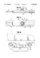
- FIG. 3is a front perspective of a typical aircraft seat frame showing a belt of this invention attached to it and showing the mounting location of the crash event sensor, electronics and inflator;
- FIG. 4is a bottom elevational of the improved belt buckle and belt tang of this invention.
- FIG. 5is a schematic of the inflator and electronic system
- FIG. 6is a view taken along the line 6--6 of FIG. 3;
- FIG. 7is a top plan view of the non-extensible portion of a lap belt on which an airbag is mounted showing the belt connecting tang and air supply elements;
- FIG. 8is a top plan view of the extensible portion of the belt showing the buckle
- FIG. 9is a partly sectional view of the non-extensible portion of a belt with parts broken away;
- FIG. 10is a side elevation showing one means for mounting an airbag on a belt
- FIG. 11is a sectional view taken along the line 11--11 of FIG. 10;
- FIG. 12is a cross-sectional view of an alternative bag/belt construction
- FIGS. 13 and 14are side and top plan views illustrating the layout of the gas supply tube and diffuser into the airbag.
- FIG. 15is a side view, partially sectioned illustrating a means for mounting the housing containing the electronic and gas supply to an aircraft seat.
- the apparatus and system of this inventioninclude a safety belt that is comprised of first and second lengths that are each fixed at one end to vehicle sub-structure and are connectable one to the other, at the other end at a location over a user's lap.
- One belt partis preferably of fixed length while the second belt length is preferably adjustable so that the combined lengths of the two belts pieces can be changed as required.
- the fixed portion of the beltcontains: (i) a deployable airbag; (ii) a torsion element which positions or orients the belt so that the bag is deployed away from the user; (iii) a gas conducting tube that directs gas from a gas source to the gas bag; and (iv) an outer, protective cover assembly that is rupturable at least in the area adjacent to the gas bag to permit its expansion.
- the systemfurther includes a source of gas, control and firing circuitry including electronics for identifying a crash event and a dedicated source of battery supplied electricity which is independent of the vehicle electrical power source and which in a preferred construction utilizes a polling or sampling means to significantly extend battery life.
- Switch meansare included in belt buckle and in belt tang parts that permit system activation when the two belt lengths are oriented correctly and joined with the airbag positioned for expansion away from the user's body. Also, by positioning switch means in the buckle and tang, activation of the airbag system can be precluded by introducing an extra belt length between the tang and buckle which precludes arming of the bag system.
- the safety belt system of this inventionmay be, as noted earlier, used in any type of passenger vehicle, it is especially applicable in those situations where two point attachment passenger restraint belts are used as the sole means of protection, for example in aircraft and in those automotive applications where rigid structure is generally not available for airbag installation.
- the greatest single area of need and therefore applicabilityis in aircraft where there has not previously been any form of seat mounted airbag protection. Due to structure and seat layout, it has been possible neither to install passenger airbags that operate in a manner similar to those in land vehicles nor to install belts that include upper torso restraint.
- the present inventioncan be used in all types of passenger vehicles, it will be described as applied to an aircraft environment where use of a totally dedicated independent power system, such as a battery, with adequate service life is mandatory.
- FIG. 1A general overview of the present passenger vehicle restraint system, including power and logic system is presented in FIG. 1, in which numeral 10 identifies what is referred to as a crash sensor module.
- Module 10is comprised of a dedicated battery power supply 11 which is completely independent of any other vehicle power source, such as a vehicle prime battery or generator.
- a dedicated, independent power sourceis provided for each individual occupant seat, so that actuation of the protective restraint airbag will be effected even though a catastrophic event may occur to the vehicle.
- crash eventsfor example, the electrical sources and systems that are used for general vehicle operation cannot be reasonably relied upon in such emergency situations.
- Dedicated battery power supply 11may preferably take the form of a lithium battery or any other battery made of materials which have performance levels and service lifetimes commensurate with realistic operational requirements.
- Battery supply 11may be advantageously made up of multiple dedicated battery units, should that arrangement be indicated in any given installation. In the present instance the use of two battery units has been found to be of particular effectiveness when placed in series with each other and circuited to provide at least two different voltage levels available to the system.
- a crash sensor 12is included as part of module 10 and usually takes the form of an accelerometer that is responsive only to accelerative (or decelerative) forces acting along a single axis that is substantially parallel to the direction of travel of the vehicle.
- System reliabilitycan be improved by employing two accelerometers that act in identical manner to provide system redundancy.
- a sensor arraycomprised of three or more individual sensors can be used to render the system responsive to forces that are not aligned identically to the axis of vehicle travel. For example, an array containing three sensors could be deployed to sense impacts occurring within ⁇ 10° of the direction of travel.
- crash sensoradvantageously incorporated into the present system is of the Hall effect type that consists of a Hall effect transducer and a spring loaded magnet.
- the magnetmoves within a tube during a deceleration event, creating an electrical signal proportional to the severity of the event, which signal can be used to trigger related apparatus that ultimately cause deployment of the airbag.
- Module 10, including components 11, 12 and 13are mounted within an electromagnetic shielding or protective cover 14 and crash sensor 12 is mounted in position within protective housing 14 through elastic shock absorbing gaskets or pads (not shown) to dampen the effect of any extraneous forces that could arise from accidental blows to the housing, as from luggage or the like.
- the crash sensor signalwill, in the preferred operation, be compared to other, stored, values so that it can initiate bag deployment only when a predetermined threshold value is created.
- the crash sensor comprised of the Hall effect deviceis uniquely adapted to elimination of signals generated by externally applied forces that are not aligned with the direction of magnet travel and where high frequency response may be detrimental.
- System electronics 13includes a micro processor and suitable programming that imparts logic capability to perform diagnostic and signal functions to initiate bag inflation once a proper signal is received from the crash sensor.
- the electronicscontrol a firing circuit that provides the electrical pulse that fires the inflator initiator, commonly referred to as a squib.
- All electronics circuitry, batteries and microprocessor chipreside on an electronics board contained within protective housing 14 that isolates them from and prevents transmission of extraneous electromagnetic radiation, such as radio frequency waves and the like.
- the shielded enclosure with the electronicswould be usually secured to a rigid plate mounted to rigid structure beneath each passenger seat. Shock absorber mounting may be used to isolate the sensor from transients generated within the aircraft, which may be transmitted through the seat frame.
- inflators 15 and 16which supply gas to the airbag 17 through gas flow path 20.
- inflators 15 and 16are shown, it will be appreciated that these are illustrative only, since one inflator or more than two inflators can be used if desired. Inflation can be effected in sequential fashion through the application of multiple inflator circuitry to provide staged bag inflation, should this type of inflation process be desired.
- gas flow control devicessuch as valves controlled by the system electronics can also provide a more gradual increase in bag inflation than would generally be possible when utilizing a single inflator having no flow rate control mechanisms.
- FIG. 1illustrates that the present restraint system can be provided with an optional pre-tensioning device 35 that functions in a known manner to remove slack from the belt 25 upon deceleration prior to deployment of airbag 17.
- the lines 40 through 45 that are drawn between the system electronics 13 of crash module 10show, as indicated by the direction of the arrows, the fashion in which commands are communicated between the system electronics and the other parts of the restraint system.
- the system electronicscan be better understood by reference to FIG. 2 of the drawing where the number 50 identifies an integrated circuit chip or microprocessor that is programmed to receive various input values, analyze the values and output appropriate command signals, as required.
- a microprocessorsuch as the Motorola MC60 HC705K1 may be used in this application.
- the battery pack 11will have two batteries which are joined in series in order that two voltages can be available for operation of the restraint system protective devices. Each battery may be a 3 volt cell which, when serially connected, provides both a 3 volt and a 6 volt output. Battery pack 11 provides 3 volt power for operation of microprocessor 50 in carrying out its logic function as well as 6 volt power to initiate the firing of the circuitry with inflators 15 and 16.
- Crash sensor 12advantageously utilizes two or more Hall effect units to generate the signals used by the logic system of microprocessor 50 to determine whether the signals are or are not representative of those that would arise from a crash event.
- multiple sensorsare not required for event sensing but the provision of multiple sensors provides greater reliability and specificity in reaction to crash events not totally aligned to the vehicle path of travel.
- two sensorsmay, if desired, enable determination of the shape of the deceleration curve so that discrimination between true crash events and unwanted transient effects such as local luggage impacts can be made; thus, inadvertent airbag deployment can be prevented.
- fastening elements 30, 31contain switch elements (described below) that when joined act to close circuit connections between battery pack 11, crash sensor 12 and system electronics 13.
- switch elementsdescribed below
- the switch elementspreclude the supplying of power from battery pack 11 to the remainder of the operating components. Inactivation of battery pack 11 preempts accidental operation and also saves battery power during periods when not required.
- Battery service lifeis a crucial aspect to a system that is to operate with no other source of operating power.
- meanshave been designed into the operating system which minimize overall operating power requirements and the time of operation and thereby effectively extend battery service life.
- power savingsis obtained by utilizing one battery to operate the digital electronics and using both batteries to meet sensor and firing circuit requirements.
- Poweris made available to the system by closing reed switch elements located on tang 30, whereby power is applied to the Hall effect sensor 12 from oscillator circuit 51 and microprocessor 50.
- the microprocessor 50waits an adjustable time period for the Hall effect sensor to stabilize and then polls the sensor using a discrete input to determine if a deployment event is occurring. If sensor 12 is inactive then the microprocessor powers down and the system enters a low current "wait" mode. After a preselected time period, the microprocessor controlled oscillator 51 powers up and the cycle repeats. The operation involves supplying discrete pulses to the Hall effect sensors, waiting for sensor stabilization and then polling the sensors to determine whether or not crash event conditions are present.
- the microprocessorreceives an input from sensor 12, the circuit stays on and the sensor is continuously monitored. If the active state remains for a preselected, adjustable threshold time the microprocessor activates bag deployment. By utilizing this on-off mode of operation, the service life of the dedicated batteries can be lengthened to the point where the system attains commercial viability. For example battery sources have expected use lifetimes of 4 to 6 months can be extended to 2.5 to 3.0 years or more of continuous 24 hour per day use.
- Tangcontains a double reed switch 55 which is closed by inserting the tang 30 into the buckle 31 in order that the battery pack 11 can be placed into the circuit to power up microprocessor 50.
- Two contactsare used in the double reed switch to provide system redundancy that delivers increased service reliability.
- Contained in buckle 31is a magnet 56 that acts to close the reed switch 55 when tang 30 is inserted into buckle 31.
- tang 30Also present in tang 30 and located to the left of reed switch 55 is an infrared sensing photo-voltaic cell 57 and a bicolor light emitting diode 58.
- the extension 59 on buckle 31extends outwardly a distance far enough to cover both the cell 57 and the LED 58.
- Numeral 60designates the circuit wires that extend along belt portion 27 both from cell 57, LED 58 and reed switch 55 to connect these elements into the microprocessor 50.
- the infared sensing photo-voltaic cell 57 and the LED 58are part of diagnostic circuitry that will be discussed more fully hereinafter.
- FIG. 4shows the belt 27 and wires 60 which connect the double reed switch 55, the IR cell 57 and the LED 58 to the microprocessor 50.
- test wand 65(illustrated diagrammatically) can be used to verify the integrity of the various parts of the sensing and firing circuitry.
- test wand 65is carried by personnel who desire to check the condition of the safety system circuits.
- magnet 66 on wand 65is placed in position adjacent to reed switch 55 to effect closing of that switch in the same fashion as magnet 56 would if the tang 30 and buckle 31 were joined.
- magnet 66be somewhat weaker than the magnet 56 which is contained in the tang of seat belt 27 so that if the test magnet 66 effects closure of switch 55, then it is known that the magnet 56 will effect similar closure.
- the protective restraint systemutilizes an inflation device as part of the operative system, provision has been made for disarming the system so that it can be safely transported for maintenance or relocation, without incurring accidental operation.
- the batteries 11 that would cause firing of squibs 68 and 69are circuited with a safing switch 70 that is held in the open condition by an arming/disarming pin 71 when the safety system electronics is positioned beneath a seat during for normal in-service operation.
- the switch 70automatically closes and shorts out the resistive firing devices that are contained in the squibs 68 and 69.
- Switch 70could be designed to operate in reverse fashion, that is to activate squibs 68 and 69 when in a normally closed condition, but the structural tolerances required to assure continued, efficient operation render this mode of operation somewhat less desirable.
- the numeral 80identifies the basic frame work of a typical seat framework structure used in commercial passenger aircraft.
- the frame 80is comprised of upper support brackets 81 and lower support brackets 82.
- Brackets 81 and 82are mounted on elongated horizontally extending tubes 83 and are spaced as required to form areas for seats and to support and secure the framework to the aircraft floor.
- the seat framework(and fully cushioned seats) is removable from attachment to the floor for relocation, removal and for any other reason.
- the protective systemis provided with crash event sensing devices, a gas supply and an independent power source, all of which are contained in protective housing 85 mounted on framework 80.
- Protective housing 85can be attached to the underside of the frame that supports the passenger seat or attached to the seat spreader bar assembly by any suitable means. Housing 85 can be understood better by referring to FIG. 6 of the drawings where numeral 86 identifies a rigid mounting plate that is secured to the seat structure. It is required that plate 86 be rigid to obtain proper sensing of a crash event through the seat structure.
- a cover shield or housing 87which includes an upper closure plate 88 is attached to plate 86 and together they define an enclosed volume 89 that holds the other components of the safety system.
- the event sensor 12is the trigger for the inflation event and through its mounting location on plate 88 it senses fore and aft deceleration of the vehicle. When it senses a preset energy value as a result of deceleration, it triggers to an inflator initiator (squib).
- the sensor used in this inventionis a "single point" sensor utilizing the Hall effect, that consists of a Hall effect transducer and a spring loaded magnet, which acts as a single axis accelerometer, all as set forth earlier.
- the magnetmoves within a tube during a deceleration event, creating an electrical signal proportional to the severity of the event, as when a given energy value is exceeded as a result of deceleration, triggering the firing circuit at the appropriate time.
- the sensoris positioned to receive input fore and aft to sense a crash event, and will not sense other inputs such as turbulence which are in an off-axis direction. Additionally, the sensor mechanically filters out higher frequency inputs, which simplifies the required algorithm and increases reliability. For greater reliability, more than one Hall effect sensor may be employed to confirm an actual crash event prior to bag deployment.
- the independent battery systememploys two separate batteries in battery pack 11 to power the firing circuit and to power the diagnostic control circuit independently.
- One batterypowers either a hybrid or integrated circuit control chip or microprocessor 50 which requires a low level current and provides the necessary logic to analyze the signal received to determine whether deployment is or is not required. Both batteries are used to power the firing circuit by providing the 6 volts required.
- inflators 15 and 16which are electronically connected to event sensor 12 by electrical leads 96.
- the electronics, battery, inflator and sensorare protected by the housing cover shield 87 from the environment under the seat pan of the passenger seat.
- Housing 87is preferably an injection molded or vacuum-formed part incorporating electronic and magnetic shielding to suppress interference that may affect the igniter or electronics and sensor.
- the inflators 15 and 16,which can be filled with any substantially inert gas such as air, nitrogen, helium, argon, etc., provide the gas output to inflate the bag located in the non-extensible belt portion 27, in a manner well known in the art.
- Gascan also be provided by a gas generator, as well as stored.
- the compressed or generated gasis created by a pyrotechnic initiator that heats stored gas or triggers a reaction, all as known in the art.
- the gaswill be released in a controlled manner upon receiving a firing signal originating from the event sensor 12.
- a gas tube 100 constructed of any suitable materialextends from the inflator upwardly alongside the passenger seat toward the end of the non-extensible belt portion 27.
- a gas coupling 101 and an electric coupling 102 for conductors 60are provided in order that the belt portion 27 can be disconnected from inflators 15 and 16 to permit maintenance or replacement of the seat belt (and belt components) or of the housing 87 and the components situated therein.
- FIG. 7there is illustrated the non-extensible part 27 of the safety belt. It comprises a length of webbing 105 which is of the type normally used in vehicle safety restraint systems. A fitting 106 is secured to the webbing at one end for fixedly attaching that end of the belt to the underlying seat sub-structure at tubing 83 and the opposite end of belt part 27 contains a tang 30 that cooperates with a suitable buckle 31 on the belt portion 26 (see FIG. 8).
- the belt part 27further comprises an airbag assembly 110 that is contained inside a cover assembly 111 and is attached directly to the fixed length of the belt on the side away from the user. Bag 17 within assembly 110 is constructed of an appropriate material, usually a tightly woven fabric, with or without an impermeable coating, depending upon performance requirements. The bag 17 will be of sufficient volume after inflation to restrain the upper body from excessive forward movement during a crash event.
- a gas supply tube 115is positioned adjacent a surface of web 105 and is permanently connected through an intermediate connection, to the end of air tube 100 at one end and to the airbag 17 at the other.
- This gas pathis contained inside the cover assembly 111 and unfolds and expands when the inflaters 15, 16 discharge gas into the system.
- the supply tube 115is shaped to provide as much occupant comfort and flexibility as possible, while still retaining its primary function of conveying gas to the bag 17.
- Supply tube 115may be substantially flat but probably cannot be totally flat since the interior gas passage must be large enough to accept the pulse of gas arising when the inflators 15, 16 are operated.
- a belt orienting devicewhich resists torsional bending of belt and maintains the non-extensible part 27 in a position in which bag assembly 110 is always positioned in a direction away from the user's body.
- Stiffener 116extends substantially the entire length of belt part 27 and is therefore of greater length than thickness and may be any type flexible strap that resists torsion, such as shipping pallet strap material or the like. Stiffener 116 will allow the belt to wrap around the occupant comfortably, yet resist twisting of the assembly about the long axis. Other systems can be provided to assure the desired belt orientation, depending upon the facts attending individual usage requirements.
- Stiffener 116may also be pre-formed to incorporate a slightly bowed or arcuate curvature that assists positioning of the belt about the user's torso.
- the stiffener orienting strap 116assists in avoiding the potential placement of an airbag assembly 110 in a hazardous position facing towards the seat occupant and may be sewn directly to the web 105 or placed in a pocket sewn to the web, or placed inside a hollow belt assembly.
- stiffener 116may be attached directly to either the belt attachment shackle 106 and/or the tang 30 in addition to the fabric belt.
- Cover assembly 111is provided to contain the folded airbag 17 on the belt during the life of the product and opens at predetermined locations to release the inflating bag during a crash event.
- Cover 111is a protective barrier for the bag material and also a decorative element of the system.
- the cover which is permanently attached to the belt at one point throughout an entire crash eventis designed to tear open at selected areas through means such as selectively weakened areas of the cover material.
- the final element on belt part 27is the tang 30 on which is mounted the dual reed switch 55 the infrared sensor 57 and the LED 58.
- Buckle 31 on belt part 26contains a magnet 56 which acts upon the reed switch 55, to close the circuit when the buckle and tongue are joined. If the buckle and tongue are rotated 180° out of proper relationship with respect to each other, the system will not be activated, thereby preventing a potentially hazardous use situation.
- This orientation assuranceis in addition to that provided by belt orienting element 116, which also acts to make sure that the orientation of the non-extensible portion 27 is such as to keep the inflatable bag assembly 110 always directed away from the body of the user.
- FIGS. 10 and 11illustrate one method by which the bag assembly 110 can be secured in operative position on the non-extensible belt portion 27.
- the bag assembly 110which includes the expansible bag 17 and cover 121, can be secured on the belt webbing 105 between caps 120.
- the bag 17can be seen in FIG. 11 in its folded and stored position and also seen is the gas supply tube 115 and the belt webbing 105 which has been shaped to receive the supply tube 115.
- the bag 17sits immediately atop the web 105 and gas tube 115 combination and is folded in the manner illustrated.
- Surrounding the entire belt assemblyis an extruded polymer sleeve 121 that extends completely between anchor caps 120.
- Sleeve 121slides over the bag and belt assembly and the caps 120 are then placed and secured in position to seal off the entire bag assembly.
- Polymer sleeve 121can be notched as shown at 122 to provide a weakened area that will rupture and permit the gas bag 17 to expand when required.
- FIG. 12shows a cross-sectional view through another configuration of bag and belt assembly, specifically, bag 17 is contained within a cover which can be similar to the polymer sleeve 121.
- Sleeve 121is fastened by suitable means such as rivets, sewing or the like to a belt assembly comprised of web 105 and a backing 123.
- the web, backing and cover sleeve 121are all joined along their longitudinal edges in the manner indicated.
- the gas supply tube 115Within the space between cover 123 and belt web 105 is the gas supply tube 115.
- the supply tube 115is of ovate shape so that the horizontal axis of the tube is greater than the vertical axis. By shaping the supply tube in this fashion, the tube may contribute in the manner of stiffener 116 to maintain the necessary orientation of the bag 17.
- the bag 17is folded and cover 121 is placed over the bag and the cover is sewn to the backing 123.
- Thisallows a tamper-proof sealed assembly that maintains the integrity of the system and precludes damage to the inflatable bag 17.
- the upper surface of cover 121is provided with a notch 122 similar to that described in connection with the configuration illustrated in FIG. 11.
- the weakened part of the coveris shown on the top surface, but may be placed advantageously in additional locations, when desired.
- the gas supply tube 115is, as already mentioned, connected at one end to the tube 100 that comes from the gas sources 15 and 16.
- FIG. 13shows the manner in which the gas is ultimately deployed into the bag. Specifically the supply tube 115 comes from the point at which the gas is being supplied from inflators 15, 16 through the belt webbing 105 and into a diffuser 125 which is located immediately beneath the location on the belt 27 where the bag 17 is located. It will be noted that the diffuser 125 is shaped with a right angle bend so that the high pressure gas coming through supply tube 115 must change direction and be diffused into the bag 17 with less force than would otherwise occur.
- the diffuser 125extends into the bag which is mounted above it and is held in place by a spacer 126 and a retainer, such as a snap ring 127.
- a diffuser fitting 128is mounted at the exit end of diffuser 125 and is formed with a plurality of side and upward facing openings 129 to diffuse and thereby reduce the velocity of the gas as it enters the bag 17.
- Other types of gas diffuser fittingsmay be used.
- FIG. 15 of the drawingsshows structure by which the apparatus of this invention can be mounted beneath an aircraft seat structure in a way in which the entire electronic and gas containing housing 85 can be removed or installed in an efficacious and safe fashion. Once the housing 85 is installed under the passenger seat the switch 70 is absolutely inaccessible to anyone, other than authorized service personnel. Specifically, all of the electronic controls 50, sensors 12, inflators 15 and 16 are contained in the housing 85 as previously discussed in connection with FIG. 6. The upper part of the enclosure is sealed with the closure plate 88 similar to that disclosed in FIG. 6.
Landscapes
- Engineering & Computer Science (AREA)
- Mechanical Engineering (AREA)
- Air Bags (AREA)
- Automotive Seat Belt Assembly (AREA)
Abstract
Description
Claims (51)
Priority Applications (12)
| Application Number | Priority Date | Filing Date | Title |
|---|---|---|---|
| US09/143,756US5984350A (en) | 1997-09-22 | 1998-08-31 | Vehicle safety system |
| CN98803835ACN1094101C (en) | 1997-09-22 | 1998-09-16 | vehicle security system |
| JP2000512709AJP2003525791A (en) | 1997-09-22 | 1998-09-16 | Vehicle safety system |
| CA002286726ACA2286726C (en) | 1997-09-22 | 1998-09-16 | Vehicle safety system |
| MXPA99008694AMXPA99008694A (en) | 1997-09-22 | 1998-09-16 | Vehicle safety system. |
| RU99122022/28ARU2204496C2 (en) | 1998-08-31 | 1998-09-16 | Vehicle passenger safety system |
| BR9809067-4ABR9809067A (en) | 1997-09-22 | 1998-09-16 | Security system for vehicles |
| KR1020007001347AKR100582508B1 (en) | 1997-09-22 | 1998-09-16 | Vehicle safety systems |
| EP98944873.3AEP1028873B1 (en) | 1997-09-22 | 1998-09-16 | Vehicle safety system |
| PCT/US1998/019343WO1999015368A1 (en) | 1997-09-22 | 1998-09-16 | Vehicle safety system |
| AU92315/98AAU746194B2 (en) | 1997-09-22 | 1998-09-16 | Vehicle safety system |
| IL13121898AIL131218A (en) | 1997-09-22 | 1998-09-16 | Vehicle safety system |
Applications Claiming Priority (3)
| Application Number | Priority Date | Filing Date | Title |
|---|---|---|---|
| US5943097P | 1997-09-22 | 1997-09-22 | |
| US3708398A | 1998-03-10 | 1998-03-10 | |
| US09/143,756US5984350A (en) | 1997-09-22 | 1998-08-31 | Vehicle safety system |
Related Parent Applications (1)
| Application Number | Title | Priority Date | Filing Date |
|---|---|---|---|
| US3708398AContinuation-In-Part | 1997-09-22 | 1998-03-10 |
Publications (1)
| Publication Number | Publication Date |
|---|---|
| US5984350Atrue US5984350A (en) | 1999-11-16 |
Family
ID=27365144
Family Applications (1)
| Application Number | Title | Priority Date | Filing Date |
|---|---|---|---|
| US09/143,756Expired - LifetimeUS5984350A (en) | 1997-09-22 | 1998-08-31 | Vehicle safety system |
Country Status (11)
| Country | Link |
|---|---|
| US (1) | US5984350A (en) |
| EP (1) | EP1028873B1 (en) |
| JP (1) | JP2003525791A (en) |
| KR (1) | KR100582508B1 (en) |
| CN (1) | CN1094101C (en) |
| AU (1) | AU746194B2 (en) |
| BR (1) | BR9809067A (en) |
| CA (1) | CA2286726C (en) |
| IL (1) | IL131218A (en) |
| MX (1) | MXPA99008694A (en) |
| WO (1) | WO1999015368A1 (en) |
Cited By (58)
| Publication number | Priority date | Publication date | Assignee | Title |
|---|---|---|---|---|
| US6095553A (en)* | 1998-06-30 | 2000-08-01 | Ford Global Technologies, Inc. | Side impact sensor system and method |
| US6282942B1 (en)* | 2000-01-19 | 2001-09-04 | Breed Automotive Technology, Inc. | Crash sensor with magnetic field sensor |
| WO2001067910A1 (en)* | 2000-03-13 | 2001-09-20 | Am-Safe Incorporated | Airbag buckle assembly |
| WO2001068413A1 (en)* | 2000-03-14 | 2001-09-20 | Am-Safe Incorporated | Air bag construction |
| US6431594B1 (en)* | 2001-01-05 | 2002-08-13 | Trw Vehicle Safety Systems Inc. | Air bag inflator with mechanism for deactivation of second stage and autoignition |
| WO2002062615A1 (en)* | 2001-02-07 | 2002-08-15 | Am-Safe Incorporated | Aircraft seat structure |
| US6438475B1 (en) | 1997-10-23 | 2002-08-20 | Breed Automotive Technology, Inc. | Crash detection system |
| US6439600B1 (en)* | 2000-03-13 | 2002-08-27 | Am-Safe, Inc. | Self-centering airbag and method for manufacturing and tuning the same |
| US6505890B2 (en)* | 2001-02-07 | 2003-01-14 | Am-Safe, Inc. | Aircraft seat structure |
| US6533316B2 (en)* | 1995-06-07 | 2003-03-18 | Automotive Technologies International, Inc. | Automotive electronic safety network |
| US6584911B2 (en)* | 2001-04-26 | 2003-07-01 | Trw Inc. | Initiators for air bag inflators |
| US6598899B2 (en) | 2001-08-21 | 2003-07-29 | Trw Inc. | Inflatable seat belt using MEMS devices |
| US6619692B2 (en) | 2001-03-27 | 2003-09-16 | Trw Inc. | Air bag inflators |
| US6641074B2 (en) | 2001-01-08 | 2003-11-04 | Trw Inc. | Seat belt webbing pretensioner using MEMS devices |
| US20040061318A1 (en)* | 2000-12-11 | 2004-04-01 | Ord Richard John | Inflation device |
| US6733036B2 (en) | 1995-06-07 | 2004-05-11 | Automotive Technologies International, Inc. | Automotive electronic safety network |
| GB2372483B (en)* | 2001-02-26 | 2004-07-28 | Autoliv Dev | Improvements in or relating to a cover for an air-bag |
| US20040239515A1 (en)* | 2001-06-02 | 2004-12-02 | Reiner Marchthaler | Device for classifying the seat occupancy in a motor vehicle |
| US20050029856A1 (en)* | 2003-08-07 | 2005-02-10 | Trw Automotive Gmbh | Device for tensioning a safety belt with a pyrotechnic linear drive |
| US6905135B2 (en) | 1995-06-07 | 2005-06-14 | Automotive Technologies International, Inc. | Inflator system |
| US6983955B2 (en) | 2001-01-05 | 2006-01-10 | Trw Inc. | Air bag inflators |
| US20060055158A1 (en)* | 2004-09-16 | 2006-03-16 | Hyundai Mobis Co., Ltd. | Seat belt of vehicle with air belt |
| US20070147272A1 (en)* | 2004-02-13 | 2007-06-28 | Alpinestars Research Srl | Garment having protective inflatable devices |
| US20070262568A1 (en)* | 2005-10-07 | 2007-11-15 | Takata Corporation | Occupant restaining apparatus |
| US20070299587A1 (en)* | 1995-10-30 | 2007-12-27 | Automotive Technologies International, Inc. | Vehicular Electrical System with Crash Sensors and Occupant Protection Systems |
| US20080125940A1 (en)* | 1995-10-30 | 2008-05-29 | Automotive Technologies International, Inc. | Electronics-Containing Airbag Module |
| US20080312795A1 (en)* | 2007-06-14 | 2008-12-18 | Young Nam Cho | System and method for classifying vehicle occupant |
| US20090243842A1 (en)* | 2008-03-31 | 2009-10-01 | Mitchell Bradley J | Methods and systems for sensing activity using energy harvesting devices |
| US20090243892A1 (en)* | 2008-03-31 | 2009-10-01 | Cheung Kwu-Wing W | Seat buckle configured for security and safety and associated methods |
| US7665761B1 (en) | 2008-03-27 | 2010-02-23 | Amsafe, Inc. | Inflatable personal restraint systems and associated methods of use and manufacture |
| US7980590B2 (en) | 2008-03-19 | 2011-07-19 | Amsafe, Inc. | Inflatable personal restraint systems having web-mounted inflators and associated methods of use and manufacture |
| US20110199976A1 (en)* | 2008-03-31 | 2011-08-18 | The Boeing Company | Wireless Aircraft Sensor Network |
| EP2508993A2 (en) | 2011-04-05 | 2012-10-10 | AmSafe, Inc. | Diagnostic self-tests on inflatable personal restraint systems |
| US20120259586A1 (en)* | 2011-04-05 | 2012-10-11 | Amsafe, Inc. | Computer system for remote testing of inflatable personal restraint systems |
| US20120256403A1 (en)* | 2011-04-05 | 2012-10-11 | Amsafe, Inc. | Activation systems for inflatable personal restraint systems |
| US20120259484A1 (en)* | 2011-04-05 | 2012-10-11 | Amsafe, Inc. | Inflatable personal restraint systems |
| US20120292893A1 (en)* | 2011-05-16 | 2012-11-22 | Amsafe, Inc. | Buckle connectors for inflatable personal restraints and associated methods of use and manufacture |
| EP2544091A2 (en) | 2011-04-05 | 2013-01-09 | AmSafe, Inc. | Computer system and graphical user interface for testing of inflatable personal restraint systems |
| US8439398B2 (en) | 2011-07-29 | 2013-05-14 | Amsafe, Inc. | Inflator connectors for inflatable personal restraints and associated systems and methods |
| US8469397B2 (en) | 2011-04-13 | 2013-06-25 | Amsafe, Inc. | Stitch patterns for restraint-mounted airbags and associated systems and methods |
| USD688156S1 (en) | 2011-05-16 | 2013-08-20 | Amsafe, Inc. | Connector for a seatbelt airbag |
| US8523220B1 (en) | 2012-03-19 | 2013-09-03 | Amsafe, Inc. | Structure mounted airbag assemblies and associated systems and methods |
| US20130325323A1 (en) | 1998-10-22 | 2013-12-05 | American Vehicular Sciences | Vehicle software upgrade techniques |
| US8672347B2 (en) | 2012-04-09 | 2014-03-18 | Autoliv Asp, Inc. | Integrated airbag restraint |
| US9022417B2 (en) | 1995-12-12 | 2015-05-05 | American Vehicular Sciences Llc | Single side curtain airbag for vehicles |
| WO2015089098A1 (en)* | 2013-12-09 | 2015-06-18 | Amsafe, Inc. | Aircraft occupant restraint pretensioning devices, systems and methods |
| US9176202B2 (en) | 2011-04-05 | 2015-11-03 | Amsafe, Inc. | Electronic module assembly for inflatable personal restraint systems and associated methods |
| US9352839B2 (en) | 2014-10-02 | 2016-05-31 | Amsafe, Inc. | Active positioning airbag assembly and associated systems and methods |
| US9428145B2 (en) | 2011-05-02 | 2016-08-30 | Takata Corporation | Electric retractor and seatbelt device |
| US9443358B2 (en) | 1995-06-07 | 2016-09-13 | Automotive Vehicular Sciences LLC | Vehicle software upgrade techniques |
| EP3075610A1 (en) | 2015-03-28 | 2016-10-05 | AmSafe, Inc. | Extending pass-through airbag occupant restraint systems, and associated systems and methods |
| US9511866B2 (en) | 2012-03-19 | 2016-12-06 | Amsafe, Inc. | Structure mounted airbag assemblies and associated systems and methods |
| US9861349B2 (en) | 2011-09-29 | 2018-01-09 | Proa Medical, Inc. | Speculum for obstetrical and gynecological exams and related procedures |
| US9925950B2 (en) | 2015-04-11 | 2018-03-27 | Amsafe, Inc. | Active airbag vent system |
| US10391960B2 (en) | 2017-02-28 | 2019-08-27 | Amsafe, Inc. | Electronic module assembly for controlling aircraft restraint systems |
| EP3556614A1 (en) | 2018-04-17 | 2019-10-23 | AmSafe, Inc. | Adjustably positionable airbag assemblies and associated systems and methods |
| US10604259B2 (en) | 2016-01-20 | 2020-03-31 | Amsafe, Inc. | Occupant restraint systems having extending restraints, and associated systems and methods |
| US11938880B2 (en) | 2018-11-01 | 2024-03-26 | Robert Bosch Gmbh | Low impact crash detection for a vehicle |
Families Citing this family (14)
| Publication number | Priority date | Publication date | Assignee | Title |
|---|---|---|---|---|
| US20020105175A1 (en)* | 1999-06-09 | 2002-08-08 | Donald J. Lewis | An inflatable seat belt anchorage and inflating system |
| ES2266447T3 (en)* | 2002-02-26 | 2007-03-01 | Dalphi Metal España, S.A. | SAFETY BELT WITH AIRBAG INCORPORATED FOR USE IN VEHICLES. |
| DE102006003794B4 (en)* | 2006-01-25 | 2008-07-10 | Autoliv Development Ab | security system |
| KR100863633B1 (en) | 2006-10-31 | 2008-10-15 | 현대자동차주식회사 | Composite primer device for vehicle airbag and its control method |
| CN101885316B (en)* | 2009-05-12 | 2012-05-23 | 上海工程技术大学 | Explosion control method and control device for explosion safety belt |
| JP2010264965A (en)* | 2009-05-18 | 2010-11-25 | Chung-Shan Inst Of Science & Technology | Vehicle personal protection device |
| CN102529871A (en)* | 2010-12-07 | 2012-07-04 | 苏州巴米特信息科技有限公司 | Novel protection method based on air bag |
| EP2596995B1 (en) | 2011-11-22 | 2014-09-17 | Zodiac Seats France | Airbag guided by seat belt |
| US9290419B2 (en)* | 2012-11-29 | 2016-03-22 | Autoliv Asp, Inc. | Duplex actuation system for inflatable restraints |
| KR101428260B1 (en) | 2012-12-10 | 2014-08-07 | 현대자동차주식회사 | Method for unfolding external air bag |
| DE102013021459A1 (en)* | 2013-12-14 | 2015-06-18 | Audi Ag | Motor vehicle with sensor to be adjusted and / or calibrated, sensor and method for monitoring a sensor |
| FR3038562B1 (en) | 2015-07-08 | 2018-05-25 | Airbus Helicopters | DEVICE FOR CONTROLLING THE INFLATION OF AN INFLATABLE SAFETY BALL, AN AIRCRAFT EQUIPPED WITH SUCH A DEVICE AND ASSOCIATED METHOD FOR INFLATION CONTROL OF AN INFLATABLE SAFETY BALL |
| US10176694B2 (en)* | 2015-09-09 | 2019-01-08 | Airbus Group India Private Limited | Aircraft occupant seat for aircraft occupant health, safety, and comfort management |
| CN112498749B (en)* | 2020-10-30 | 2022-09-06 | 北京空间机电研究所 | Flexible deployable initiative defense device |
Citations (19)
| Publication number | Priority date | Publication date | Assignee | Title |
|---|---|---|---|---|
| US3430979A (en)* | 1966-11-17 | 1969-03-04 | Chrysler Corp | Inflatable cushioning device |
| US3888503A (en)* | 1973-02-22 | 1975-06-10 | Allied Chem | Limiting of continuous extent of inflatable restraint |
| US3948541A (en)* | 1974-06-27 | 1976-04-06 | The United States Of America As Represented By The Secretary Of The Navy | Inflatable body and head restraint |
| US4107604A (en)* | 1976-12-01 | 1978-08-15 | Compunetics, Incorporated | Hall effect displacement transducer using a bar magnet parallel to the plane of the Hall device |
| US4611491A (en)* | 1984-05-05 | 1986-09-16 | Ferranti Plc | Accelerometer system |
| US4722573A (en)* | 1985-09-30 | 1988-02-02 | Ikeda Bussan Co., Ltd. | Seat belt-equipped seat assembly |
| JPS6483436A (en)* | 1987-09-25 | 1989-03-29 | Mitsuharu Yamaguchi | Inflation type restraining device |
| US4987783A (en)* | 1986-02-28 | 1991-01-29 | Antonio Nicholas F D | Sensor and transducer apparatus |
| US4995640A (en)* | 1989-06-12 | 1991-02-26 | Nippon Seiko Kabushiki Kaisha | Magnetic sensor actuation system suitable for use in passive seat belt system |
| US5026305A (en)* | 1990-06-28 | 1991-06-25 | Amp Incorporated | Connector for reed switch or similar electrical component |
| US5184844A (en)* | 1990-11-27 | 1993-02-09 | Goor Associates, Inc. | Integral inflatable occupant restraint system |
| US5194755A (en)* | 1991-03-04 | 1993-03-16 | Ford Motor Company | Airbag triggering system |
| US5456491A (en)* | 1994-08-16 | 1995-10-10 | Chen; Fou-Min | Air bag received in a safety belt |
| US5473111A (en)* | 1992-10-07 | 1995-12-05 | Mitsubishi Denki Kabushiki Kaisha | Shielded enclosure for housing electronic components and manufacturing method thereof |
| US5485041A (en)* | 1990-11-19 | 1996-01-16 | Meister; Jack B. | Impact sensor for vehicle safety restraint system |
| US5597178A (en)* | 1994-08-18 | 1997-01-28 | Hardin, Jr.; Paul W. | Seatbelt airbag |
| US5672916A (en)* | 1995-02-17 | 1997-09-30 | Morton International, Inc. | Seat belt latch sensor |
| US5734318A (en)* | 1995-07-27 | 1998-03-31 | Robert Bosch Gmbh | Electronic device |
| US5765869A (en)* | 1996-09-06 | 1998-06-16 | Huber; John F. | Automatically tightened seatbelt |
Family Cites Families (13)
| Publication number | Priority date | Publication date | Assignee | Title |
|---|---|---|---|---|
| US2639852A (en)* | 1946-09-07 | 1953-05-26 | Goodrich Co B F | Safety belt |
| US2710999A (en)* | 1952-02-28 | 1955-06-21 | Davis Aircraft Products Inc | Quick releasable buckle for safety belts |
| US3706463A (en)* | 1970-02-24 | 1972-12-19 | Martin Lipkin | Inflatable safety balloon with inertial means of actuation |
| DE2442726A1 (en)* | 1974-09-06 | 1976-03-25 | Rutzki Geb Wilke | Vehicle safety belt lock - has releasable lock plate on belt connected to vehicle door latch |
| DE2808872C2 (en)* | 1978-03-02 | 1986-01-23 | Messerschmitt-Bölkow-Blohm GmbH, 8000 München | Trigger circuit for an occupant protection device in motor vehicles |
| DE3518502C2 (en)* | 1985-05-23 | 1987-03-05 | Daimler-Benz Ag, 7000 Stuttgart | Release device for restraint systems in motor vehicles |
| US4950914A (en)* | 1987-03-30 | 1990-08-21 | Honda Giken Kogyo Kabushiki Kaisha | Collision detection system for a vehicle |
| SE460535B (en)* | 1987-04-14 | 1989-10-23 | Karlo Smit | SAFETY BELT IN VEHICLES WITH AUTOMATICALLY OPERATING STRAECK AND SAFETY |
| DE3829784A1 (en)* | 1988-09-02 | 1990-03-15 | Bosch Gmbh Robert | EVALUATION PROCESS FOR SENSOR OUTPUT SIGNALS |
| JP2905240B2 (en)* | 1990-02-07 | 1999-06-14 | アスコ株式会社 | Control system for vehicle safety equipment |
| JPH05238348A (en)* | 1991-03-13 | 1993-09-17 | Zexel Corp | Control system for vehicle safety device |
| KR960008806B1 (en)* | 1994-01-28 | 1996-07-05 | 조성호 | Car air safety belt |
| WO1997006983A1 (en)* | 1995-08-16 | 1997-02-27 | Simula Inc. | Inflatable tubular restraint system |
- 1998
- 1998-08-31USUS09/143,756patent/US5984350A/ennot_activeExpired - Lifetime
- 1998-09-16EPEP98944873.3Apatent/EP1028873B1/ennot_activeExpired - Lifetime
- 1998-09-16JPJP2000512709Apatent/JP2003525791A/enactivePending
- 1998-09-16ILIL13121898Apatent/IL131218A/ennot_activeIP Right Cessation
- 1998-09-16WOPCT/US1998/019343patent/WO1999015368A1/enactiveIP Right Grant
- 1998-09-16AUAU92315/98Apatent/AU746194B2/ennot_activeExpired
- 1998-09-16BRBR9809067-4Apatent/BR9809067A/ennot_activeIP Right Cessation
- 1998-09-16KRKR1020007001347Apatent/KR100582508B1/ennot_activeExpired - Lifetime
- 1998-09-16CNCN98803835Apatent/CN1094101C/ennot_activeExpired - Lifetime
- 1998-09-16CACA002286726Apatent/CA2286726C/ennot_activeExpired - Lifetime
- 1998-09-16MXMXPA99008694Apatent/MXPA99008694A/enactiveIP Right Grant
Patent Citations (19)
| Publication number | Priority date | Publication date | Assignee | Title |
|---|---|---|---|---|
| US3430979A (en)* | 1966-11-17 | 1969-03-04 | Chrysler Corp | Inflatable cushioning device |
| US3888503A (en)* | 1973-02-22 | 1975-06-10 | Allied Chem | Limiting of continuous extent of inflatable restraint |
| US3948541A (en)* | 1974-06-27 | 1976-04-06 | The United States Of America As Represented By The Secretary Of The Navy | Inflatable body and head restraint |
| US4107604A (en)* | 1976-12-01 | 1978-08-15 | Compunetics, Incorporated | Hall effect displacement transducer using a bar magnet parallel to the plane of the Hall device |
| US4611491A (en)* | 1984-05-05 | 1986-09-16 | Ferranti Plc | Accelerometer system |
| US4722573A (en)* | 1985-09-30 | 1988-02-02 | Ikeda Bussan Co., Ltd. | Seat belt-equipped seat assembly |
| US4987783A (en)* | 1986-02-28 | 1991-01-29 | Antonio Nicholas F D | Sensor and transducer apparatus |
| JPS6483436A (en)* | 1987-09-25 | 1989-03-29 | Mitsuharu Yamaguchi | Inflation type restraining device |
| US4995640A (en)* | 1989-06-12 | 1991-02-26 | Nippon Seiko Kabushiki Kaisha | Magnetic sensor actuation system suitable for use in passive seat belt system |
| US5026305A (en)* | 1990-06-28 | 1991-06-25 | Amp Incorporated | Connector for reed switch or similar electrical component |
| US5485041A (en)* | 1990-11-19 | 1996-01-16 | Meister; Jack B. | Impact sensor for vehicle safety restraint system |
| US5184844A (en)* | 1990-11-27 | 1993-02-09 | Goor Associates, Inc. | Integral inflatable occupant restraint system |
| US5194755A (en)* | 1991-03-04 | 1993-03-16 | Ford Motor Company | Airbag triggering system |
| US5473111A (en)* | 1992-10-07 | 1995-12-05 | Mitsubishi Denki Kabushiki Kaisha | Shielded enclosure for housing electronic components and manufacturing method thereof |
| US5456491A (en)* | 1994-08-16 | 1995-10-10 | Chen; Fou-Min | Air bag received in a safety belt |
| US5597178A (en)* | 1994-08-18 | 1997-01-28 | Hardin, Jr.; Paul W. | Seatbelt airbag |
| US5672916A (en)* | 1995-02-17 | 1997-09-30 | Morton International, Inc. | Seat belt latch sensor |
| US5734318A (en)* | 1995-07-27 | 1998-03-31 | Robert Bosch Gmbh | Electronic device |
| US5765869A (en)* | 1996-09-06 | 1998-06-16 | Huber; John F. | Automatically tightened seatbelt |
Cited By (92)
| Publication number | Priority date | Publication date | Assignee | Title |
|---|---|---|---|---|
| US9443358B2 (en) | 1995-06-07 | 2016-09-13 | Automotive Vehicular Sciences LLC | Vehicle software upgrade techniques |
| US6905135B2 (en) | 1995-06-07 | 2005-06-14 | Automotive Technologies International, Inc. | Inflator system |
| US6533316B2 (en)* | 1995-06-07 | 2003-03-18 | Automotive Technologies International, Inc. | Automotive electronic safety network |
| US6733036B2 (en) | 1995-06-07 | 2004-05-11 | Automotive Technologies International, Inc. | Automotive electronic safety network |
| US7580782B2 (en) | 1995-10-30 | 2009-08-25 | Automotive Technologies International, Inc. | Vehicular electronic system with crash sensors and occupant protection systems |
| US7774115B2 (en)* | 1995-10-30 | 2010-08-10 | Automotive Technologies International, Inc. | Electronics-containing airbag module |
| US20080125940A1 (en)* | 1995-10-30 | 2008-05-29 | Automotive Technologies International, Inc. | Electronics-Containing Airbag Module |
| US7657354B2 (en) | 1995-10-30 | 2010-02-02 | Automotive Technologies International, Inc. | Vehicular electronic system with crash sensors and occupant protection systems |
| US20070299587A1 (en)* | 1995-10-30 | 2007-12-27 | Automotive Technologies International, Inc. | Vehicular Electrical System with Crash Sensors and Occupant Protection Systems |
| US9022417B2 (en) | 1995-12-12 | 2015-05-05 | American Vehicular Sciences Llc | Single side curtain airbag for vehicles |
| US6438475B1 (en) | 1997-10-23 | 2002-08-20 | Breed Automotive Technology, Inc. | Crash detection system |
| US6095553A (en)* | 1998-06-30 | 2000-08-01 | Ford Global Technologies, Inc. | Side impact sensor system and method |
| US10240935B2 (en) | 1998-10-22 | 2019-03-26 | American Vehicular Sciences Llc | Vehicle software upgrade techniques |
| US20130325323A1 (en) | 1998-10-22 | 2013-12-05 | American Vehicular Sciences | Vehicle software upgrade techniques |
| US6282942B1 (en)* | 2000-01-19 | 2001-09-04 | Breed Automotive Technology, Inc. | Crash sensor with magnetic field sensor |
| US6439600B1 (en)* | 2000-03-13 | 2002-08-27 | Am-Safe, Inc. | Self-centering airbag and method for manufacturing and tuning the same |
| US6442807B1 (en)* | 2000-03-13 | 2002-09-03 | Am-Safe, Inc. | Airbag buckle assembly |
| WO2001067910A1 (en)* | 2000-03-13 | 2001-09-20 | Am-Safe Incorporated | Airbag buckle assembly |
| EP1276644A4 (en)* | 2000-03-13 | 2005-02-16 | Am Safe Inc | Self-centering airbag and manufacturing method |
| WO2001068413A1 (en)* | 2000-03-14 | 2001-09-20 | Am-Safe Incorporated | Air bag construction |
| US20040061318A1 (en)* | 2000-12-11 | 2004-04-01 | Ord Richard John | Inflation device |
| US6431594B1 (en)* | 2001-01-05 | 2002-08-13 | Trw Vehicle Safety Systems Inc. | Air bag inflator with mechanism for deactivation of second stage and autoignition |
| US6983955B2 (en) | 2001-01-05 | 2006-01-10 | Trw Inc. | Air bag inflators |
| US6641074B2 (en) | 2001-01-08 | 2003-11-04 | Trw Inc. | Seat belt webbing pretensioner using MEMS devices |
| WO2002062615A1 (en)* | 2001-02-07 | 2002-08-15 | Am-Safe Incorporated | Aircraft seat structure |
| US6505890B2 (en)* | 2001-02-07 | 2003-01-14 | Am-Safe, Inc. | Aircraft seat structure |
| GB2372483B (en)* | 2001-02-26 | 2004-07-28 | Autoliv Dev | Improvements in or relating to a cover for an air-bag |
| US6619692B2 (en) | 2001-03-27 | 2003-09-16 | Trw Inc. | Air bag inflators |
| US6584911B2 (en)* | 2001-04-26 | 2003-07-01 | Trw Inc. | Initiators for air bag inflators |
| US7161474B2 (en)* | 2001-06-02 | 2007-01-09 | Robert Bosch Gmbh | Device for classifying the seat occupancy in a motor vehicle |
| US20040239515A1 (en)* | 2001-06-02 | 2004-12-02 | Reiner Marchthaler | Device for classifying the seat occupancy in a motor vehicle |
| US6598899B2 (en) | 2001-08-21 | 2003-07-29 | Trw Inc. | Inflatable seat belt using MEMS devices |
| US20050029856A1 (en)* | 2003-08-07 | 2005-02-10 | Trw Automotive Gmbh | Device for tensioning a safety belt with a pyrotechnic linear drive |
| US6966607B2 (en)* | 2003-08-07 | 2005-11-22 | Trw Automotive Gmbh | Device for tensioning a safety belt with a pyrotechnic linear drive |
| US7460886B2 (en)* | 2004-02-13 | 2008-12-02 | Alpinestars Research Srl | Garment having protective inflatable devices |
| US20070147272A1 (en)* | 2004-02-13 | 2007-06-28 | Alpinestars Research Srl | Garment having protective inflatable devices |
| US7481451B2 (en)* | 2004-09-16 | 2009-01-27 | Hyundai Mobis Co., Ltd. | Seat belt of vehicle with air belt |
| US20060055158A1 (en)* | 2004-09-16 | 2006-03-16 | Hyundai Mobis Co., Ltd. | Seat belt of vehicle with air belt |
| US20070262568A1 (en)* | 2005-10-07 | 2007-11-15 | Takata Corporation | Occupant restaining apparatus |
| US7991530B2 (en)* | 2007-06-14 | 2011-08-02 | Kia Motors Corp. | System and method for classifying vehicle occupant |
| US20110202311A1 (en)* | 2007-06-14 | 2011-08-18 | Kia Motors Corporation | System and method for classifying vehicle occupant |
| US20080312795A1 (en)* | 2007-06-14 | 2008-12-18 | Young Nam Cho | System and method for classifying vehicle occupant |
| US7980590B2 (en) | 2008-03-19 | 2011-07-19 | Amsafe, Inc. | Inflatable personal restraint systems having web-mounted inflators and associated methods of use and manufacture |
| US7665761B1 (en) | 2008-03-27 | 2010-02-23 | Amsafe, Inc. | Inflatable personal restraint systems and associated methods of use and manufacture |
| US20110199976A1 (en)* | 2008-03-31 | 2011-08-18 | The Boeing Company | Wireless Aircraft Sensor Network |
| US8274383B2 (en) | 2008-03-31 | 2012-09-25 | The Boeing Company | Methods and systems for sensing activity using energy harvesting devices |
| US8344912B2 (en) | 2008-03-31 | 2013-01-01 | The Boeing Company | Wireless aircraft sensor network |
| US20090243892A1 (en)* | 2008-03-31 | 2009-10-01 | Cheung Kwu-Wing W | Seat buckle configured for security and safety and associated methods |
| US20090243842A1 (en)* | 2008-03-31 | 2009-10-01 | Mitchell Bradley J | Methods and systems for sensing activity using energy harvesting devices |
| US8427294B2 (en)* | 2008-03-31 | 2013-04-23 | The Boeing Company | Seat buckle configured for security and safety and associated methods |
| US20120256403A1 (en)* | 2011-04-05 | 2012-10-11 | Amsafe, Inc. | Activation systems for inflatable personal restraint systems |
| CN102841597B (en)* | 2011-04-05 | 2015-11-18 | Am-安全公司 | The computer system of the inflatable individual constrained system of remote testing |
| EP2527941A1 (en) | 2011-04-05 | 2012-11-28 | AmSafe, Inc. | Computer system for remote testing of inflatable personal restraint systems |
| EP2544091A2 (en) | 2011-04-05 | 2013-01-09 | AmSafe, Inc. | Computer system and graphical user interface for testing of inflatable personal restraint systems |
| US8403361B2 (en)* | 2011-04-05 | 2013-03-26 | Amsafe, Inc. | Activation systems for inflatable personal restraint systems |
| US12227294B2 (en) | 2011-04-05 | 2025-02-18 | Amsafe, Inc. | Inflatable personal restraint systems |
| US11628937B2 (en) | 2011-04-05 | 2023-04-18 | Amsafe, Inc. | Inflatable personal restraint systems |
| US10364034B2 (en)* | 2011-04-05 | 2019-07-30 | Amsafe, Inc. | Circuitry for testing inflatable personal restraint systems |
| EP2508993A2 (en) | 2011-04-05 | 2012-10-10 | AmSafe, Inc. | Diagnostic self-tests on inflatable personal restraint systems |
| US20120259586A1 (en)* | 2011-04-05 | 2012-10-11 | Amsafe, Inc. | Computer system for remote testing of inflatable personal restraint systems |
| US20160096625A1 (en)* | 2011-04-05 | 2016-04-07 | Amsafe, Inc. | Inflatable personal restraint systems |
| US20120259484A1 (en)* | 2011-04-05 | 2012-10-11 | Amsafe, Inc. | Inflatable personal restraint systems |
| CN102841597A (en)* | 2011-04-05 | 2012-12-26 | Am-安全公司 | Computer system for remote testing of inflatable personal restraint systems |
| US8818759B2 (en)* | 2011-04-05 | 2014-08-26 | Amsafe, Inc. | Computer system for remote testing of inflatable personal restraint systems |
| US8914188B2 (en)* | 2011-04-05 | 2014-12-16 | Amsafe, Inc. | Computer system and graphical user interface for testing of inflatable personal restraint systems |
| TWI465900B (en)* | 2011-04-05 | 2014-12-21 | Amsafe Inc | Computer system and graphical user interface for testing of inflatable personal restraint systems |
| US20120259503A1 (en)* | 2011-04-05 | 2012-10-11 | Amsafe, Inc. | Computer system and graphical user interface for testing of inflatable personal restraint systems |
| US9176202B2 (en) | 2011-04-05 | 2015-11-03 | Amsafe, Inc. | Electronic module assembly for inflatable personal restraint systems and associated methods |
| US9153080B2 (en) | 2011-04-05 | 2015-10-06 | Amsafe, Inc. | Computer system for remote testing of inflatable personal restraint systems |
| US9156558B2 (en)* | 2011-04-05 | 2015-10-13 | Amsafe, Inc. | Inflatable personal restraint systems |
| US8469397B2 (en) | 2011-04-13 | 2013-06-25 | Amsafe, Inc. | Stitch patterns for restraint-mounted airbags and associated systems and methods |
| US9428145B2 (en) | 2011-05-02 | 2016-08-30 | Takata Corporation | Electric retractor and seatbelt device |
| US20120292893A1 (en)* | 2011-05-16 | 2012-11-22 | Amsafe, Inc. | Buckle connectors for inflatable personal restraints and associated methods of use and manufacture |
| US8556293B2 (en)* | 2011-05-16 | 2013-10-15 | Amsafe, Inc. | Buckle connectors for inflatable personal restraints and associated methods of use and manufacture |
| USD688156S1 (en) | 2011-05-16 | 2013-08-20 | Amsafe, Inc. | Connector for a seatbelt airbag |
| US8439398B2 (en) | 2011-07-29 | 2013-05-14 | Amsafe, Inc. | Inflator connectors for inflatable personal restraints and associated systems and methods |
| US9861349B2 (en) | 2011-09-29 | 2018-01-09 | Proa Medical, Inc. | Speculum for obstetrical and gynecological exams and related procedures |
| US9907544B2 (en)* | 2011-09-29 | 2018-03-06 | Proa Medical, Inc. | Minimally obstructive retractor for vaginal repairs |
| US8523220B1 (en) | 2012-03-19 | 2013-09-03 | Amsafe, Inc. | Structure mounted airbag assemblies and associated systems and methods |
| US9511866B2 (en) | 2012-03-19 | 2016-12-06 | Amsafe, Inc. | Structure mounted airbag assemblies and associated systems and methods |
| US9889937B2 (en) | 2012-03-19 | 2018-02-13 | Amsafe, Inc. | Structure mounted airbag assemblies and associated systems and methods |
| US8672347B2 (en) | 2012-04-09 | 2014-03-18 | Autoliv Asp, Inc. | Integrated airbag restraint |
| WO2015089098A1 (en)* | 2013-12-09 | 2015-06-18 | Amsafe, Inc. | Aircraft occupant restraint pretensioning devices, systems and methods |
| US9352839B2 (en) | 2014-10-02 | 2016-05-31 | Amsafe, Inc. | Active positioning airbag assembly and associated systems and methods |
| US9944245B2 (en) | 2015-03-28 | 2018-04-17 | Amsafe, Inc. | Extending pass-through airbag occupant restraint systems, and associated systems and methods |
| EP3075610A1 (en) | 2015-03-28 | 2016-10-05 | AmSafe, Inc. | Extending pass-through airbag occupant restraint systems, and associated systems and methods |
| US9925950B2 (en) | 2015-04-11 | 2018-03-27 | Amsafe, Inc. | Active airbag vent system |
| US10604259B2 (en) | 2016-01-20 | 2020-03-31 | Amsafe, Inc. | Occupant restraint systems having extending restraints, and associated systems and methods |
| US10391960B2 (en) | 2017-02-28 | 2019-08-27 | Amsafe, Inc. | Electronic module assembly for controlling aircraft restraint systems |
| US11021123B2 (en) | 2017-02-28 | 2021-06-01 | Amsafe, Inc. | Electronic module assembly for controlling aircraft restraint systems |
| EP3556614A1 (en) | 2018-04-17 | 2019-10-23 | AmSafe, Inc. | Adjustably positionable airbag assemblies and associated systems and methods |
| US11938880B2 (en) | 2018-11-01 | 2024-03-26 | Robert Bosch Gmbh | Low impact crash detection for a vehicle |
Also Published As
| Publication number | Publication date |
|---|---|
| IL131218A (en) | 2002-07-25 |
| KR20010022748A (en) | 2001-03-26 |
| CN1275950A (en) | 2000-12-06 |
| MXPA99008694A (en) | 2004-09-01 |
| JP2003525791A (en) | 2003-09-02 |
| WO1999015368A1 (en) | 1999-04-01 |
| EP1028873A1 (en) | 2000-08-23 |
| CN1094101C (en) | 2002-11-13 |
| AU746194B2 (en) | 2002-04-18 |
| KR100582508B1 (en) | 2006-05-23 |
| CA2286726A1 (en) | 1999-04-01 |
| EP1028873A4 (en) | 2002-09-11 |
| CA2286726C (en) | 2004-05-25 |
| EP1028873B1 (en) | 2013-05-01 |
| AU9231598A (en) | 1999-04-12 |
| BR9809067A (en) | 2000-08-08 |
| IL131218A0 (en) | 2001-01-28 |
Similar Documents
| Publication | Publication Date | Title |
|---|---|---|
| US5984350A (en) | Vehicle safety system | |
| US5184844A (en) | Integral inflatable occupant restraint system | |
| JP5853306B2 (en) | Structure-attached airbag assembly and related systems and methods | |
| US9376076B2 (en) | Method and apparatus for deployment of an air bag | |
| US5390952A (en) | Integral inflatable occupant restraint system | |
| US20080054602A1 (en) | Passenger side twin airbag module assembly | |
| US10604259B2 (en) | Occupant restraint systems having extending restraints, and associated systems and methods | |
| US20020105219A1 (en) | Aircraft seat structure | |
| US20200298984A1 (en) | Airbag systems for use on aircraft | |
| US20200290545A1 (en) | Airbag systems for use on aircraft | |
| US20170203847A1 (en) | Occupant restraint systems having extending restraints, and associated systems and methods | |
| US5779304A (en) | Child safety seat with self-contained air bag | |
| US20190315470A1 (en) | Adjustably positionable airbag assemblies and associated systems and methods | |
| WO2002062615A1 (en) | Aircraft seat structure | |
| US6581961B1 (en) | Deactivation of second stage of air bag inflator | |
| US20210214092A1 (en) | Structure mounted airbag systems | |
| AU758626B2 (en) | Vehicle safety system | |
| RU2204496C2 (en) | Vehicle passenger safety system | |
| US20020105175A1 (en) | An inflatable seat belt anchorage and inflating system | |
| HK1030912A1 (en) | Vehicle safety system | |
| HK1030912B (en) | Vehicle safety system | |
| EP1363803A1 (en) | Aircraft seat structure | |
| HK1193381A (en) | Structure mounted airbag assemblies and associated systems and methods |
Legal Events
| Date | Code | Title | Description |
|---|---|---|---|
| AS | Assignment | Owner name:AM-SAFE, INCORPORATED, ARIZONA Free format text:ASSIGNMENT OF ASSIGNORS INTEREST;ASSIGNORS:HAGAN, WILLARD F.;ZOLLINGER, LINDSAY P.;COLEMAN, DANIEL E.;AND OTHERS;REEL/FRAME:009433/0498;SIGNING DATES FROM 19980810 TO 19980828 | |
| STCF | Information on status: patent grant | Free format text:PATENTED CASE | |
| FPAY | Fee payment | Year of fee payment:4 | |
| FEPP | Fee payment procedure | Free format text:PAYOR NUMBER ASSIGNED (ORIGINAL EVENT CODE: ASPN); ENTITY STATUS OF PATENT OWNER: LARGE ENTITY Free format text:PAYER NUMBER DE-ASSIGNED (ORIGINAL EVENT CODE: RMPN); ENTITY STATUS OF PATENT OWNER: LARGE ENTITY | |
| FPAY | Fee payment | Year of fee payment:8 | |
| SULP | Surcharge for late payment | Year of fee payment:7 | |
| AS | Assignment | Owner name:WELLS FARGO BANK, NATIONAL ASSOCIATION, CALIFORNIA Free format text:SECURITY AGREEMENT;ASSIGNOR:AMSAFE, INC.;REEL/FRAME:020218/0987 Effective date:20071026 | |
| FPAY | Fee payment | Year of fee payment:12 | |
| AS | Assignment | Owner name:AMSAFE, INC., ARIZONA Free format text:RELEASE BY SECURED PARTY;ASSIGNOR:WELLS FARGO BANK, NATIONAL ASSOCIATION;REEL/FRAME:026637/0080 Effective date:20110722 Owner name:ARES CAPITAL CORPORATION, AS ADMINISTRATIVE AGENT, Free format text:SECURITY AGREEMENT;ASSIGNORS:AMSAFE, INC.;AMSAFE COMMERCIAL PRODUCTS. INC.;AMSAFE AVIATION, INC.;REEL/FRAME:026637/0591 Effective date:20110722 | |
| AS | Assignment | Owner name:AMSAFE AVIATION, INC., GEORGIA Free format text:TERMINATION AND SECURITY RELEASE;ASSIGNOR:ARES CAPITAL CORPORATION;REEL/FRAME:027830/0048 Effective date:20120215 Owner name:AMSAFE COMMERCIAL PRODUCTS, INC., INDIANA Free format text:TERMINATION AND SECURITY RELEASE;ASSIGNOR:ARES CAPITAL CORPORATION;REEL/FRAME:027830/0048 Effective date:20120215 Owner name:AMSAFE, INC., ARIZONA Free format text:TERMINATION AND SECURITY RELEASE;ASSIGNOR:ARES CAPITAL CORPORATION;REEL/FRAME:027830/0048 Effective date:20120215 | |
| AS | Assignment | Owner name:CREDIT SUISSE AG, NEW YORK Free format text:SECURITY AGREEMENT;ASSIGNORS:AMSAFE, INC.;AMSAFE COMMERCIAL PRODUCTS, INC.;AMSAFE AVIATION, INC.;REEL/FRAME:027830/0183 Effective date:20120215 | |
| AS | Assignment | Owner name:AMSAFE, INC., ARIZONA Free format text:CHANGE OF NAME;ASSIGNOR:AM-SAFE, INC.;REEL/FRAME:028158/0219 Effective date:20070404 | |
| AS | Assignment | Owner name:THE BANK OF NEW YORK MELLON TRUST COMPANY, N.A.,, Free format text:SECURITY INTEREST;ASSIGNORS:TRANSDIGM, INC.;ADAMS RITE AEROSPACE, INC.;AEROCONTROLEX GROUP, INC.;AND OTHERS;REEL/FRAME:048365/0499 Effective date:20190214 | |
| AS | Assignment | Owner name:THE BANK OF NEW YORK MELLON TRUST COMPANY, N.A., AS TRUSTEE AND NOTES COLLATERAL AGENT, ILLINOIS Free format text:PATENT SECURITY AGREEMENT;ASSIGNORS:AIRBORNE SYSTEMS NORTH AMERICA OF NJ INC.;ACME AEROSPACE, INC.;ADAMS RITE AEROSPACE, INC.;AND OTHERS;REEL/FRAME:052352/0704 Effective date:20200408 | |
| AS | Assignment | Owner name:APICAL INDUSTRIES, INC., OHIO Free format text:RELEASE BY SECURED PARTY;ASSIGNOR:THE BANK OF NEW YORK MELLON TRUST COMPANY, N.A., AS TRUSTEE;REEL/FRAME:063363/0753 Effective date:20230410 Owner name:SIMPLEX MANUFACTURING CO., OHIO Free format text:RELEASE BY SECURED PARTY;ASSIGNOR:THE BANK OF NEW YORK MELLON TRUST COMPANY, N.A., AS TRUSTEE;REEL/FRAME:063363/0753 Effective date:20230410 Owner name:CHELTON, INC. (N/K/A CHELTON AVIONICS, INC.), ARIZONA Free format text:RELEASE BY SECURED PARTY;ASSIGNOR:THE BANK OF NEW YORK MELLON TRUST COMPANY, N.A., AS TRUSTEE;REEL/FRAME:063363/0753 Effective date:20230410 Owner name:PALOMAR PRODUCTS, INC., CALIFORNIA Free format text:RELEASE BY SECURED PARTY;ASSIGNOR:THE BANK OF NEW YORK MELLON TRUST COMPANY, N.A., AS TRUSTEE;REEL/FRAME:063363/0753 Effective date:20230410 Owner name:KORRY ELECTRONICS CO., WASHINGTON Free format text:RELEASE BY SECURED PARTY;ASSIGNOR:THE BANK OF NEW YORK MELLON TRUST COMPANY, N.A., AS TRUSTEE;REEL/FRAME:063363/0753 Effective date:20230410 Owner name:MASON ELECTRIC CO., CALIFORNIA Free format text:RELEASE BY SECURED PARTY;ASSIGNOR:THE BANK OF NEW YORK MELLON TRUST COMPANY, N.A., AS TRUSTEE;REEL/FRAME:063363/0753 Effective date:20230410 Owner name:TA AEROSPACE CO., CALIFORNIA Free format text:RELEASE BY SECURED PARTY;ASSIGNOR:THE BANK OF NEW YORK MELLON TRUST COMPANY, N.A., AS TRUSTEE;REEL/FRAME:063363/0753 Effective date:20230410 Owner name:NMC GROUP INC., CALIFORNIA Free format text:RELEASE BY SECURED PARTY;ASSIGNOR:THE BANK OF NEW YORK MELLON TRUST COMPANY, N.A., AS TRUSTEE;REEL/FRAME:063363/0753 Effective date:20230410 Owner name:LEACH INTERNATIONAL CORPORATION, CALIFORNIA Free format text:RELEASE BY SECURED PARTY;ASSIGNOR:THE BANK OF NEW YORK MELLON TRUST COMPANY, N.A., AS TRUSTEE;REEL/FRAME:063363/0753 Effective date:20230410 Owner name:ARMTEC DEFENSE PRODUCTS COMPANY, CALIFORNIA Free format text:RELEASE BY SECURED PARTY;ASSIGNOR:THE BANK OF NEW YORK MELLON TRUST COMPANY, N.A., AS TRUSTEE;REEL/FRAME:063363/0753 Effective date:20230410 Owner name:ARMTEC COUNTERMEASURES CO., NORTH CAROLINA Free format text:RELEASE BY SECURED PARTY;ASSIGNOR:THE BANK OF NEW YORK MELLON TRUST COMPANY, N.A., AS TRUSTEE;REEL/FRAME:063363/0753 Effective date:20230410 Owner name:YOUNG & FRANKLIN INC., NEW YORK Free format text:RELEASE BY SECURED PARTY;ASSIGNOR:THE BANK OF NEW YORK MELLON TRUST COMPANY, N.A., AS TRUSTEE;REEL/FRAME:063363/0753 Effective date:20230410 Owner name:WHIPPANY ACTUATION SYSTEMS, LLC, NEW JERSEY Free format text:RELEASE BY SECURED PARTY;ASSIGNOR:THE BANK OF NEW YORK MELLON TRUST COMPANY, N.A., AS TRUSTEE;REEL/FRAME:063363/0753 Effective date:20230410 Owner name:WESTERN SKY INDUSTRIES, LLC, KENTUCKY Free format text:RELEASE BY SECURED PARTY;ASSIGNOR:THE BANK OF NEW YORK MELLON TRUST COMPANY, N.A., AS TRUSTEE;REEL/FRAME:063363/0753 Effective date:20230410 Owner name:TRANSCOIL LLC, PENNSYLVANIA Free format text:RELEASE BY SECURED PARTY;ASSIGNOR:THE BANK OF NEW YORK MELLON TRUST COMPANY, N.A., AS TRUSTEE;REEL/FRAME:063363/0753 Effective date:20230410 Owner name:TELAIR INTERNATIONAL LLC, NEW YORK Free format text:RELEASE BY SECURED PARTY;ASSIGNOR:THE BANK OF NEW YORK MELLON TRUST COMPANY, N.A., AS TRUSTEE;REEL/FRAME:063363/0753 Effective date:20230410 Owner name:TEAC AEROSPACE TECHNOLOGIES, INC., FLORIDA Free format text:RELEASE BY SECURED PARTY;ASSIGNOR:THE BANK OF NEW YORK MELLON TRUST COMPANY, N.A., AS TRUSTEE;REEL/FRAME:063363/0753 Effective date:20230410 Owner name:TACTAIR FLUID CONTROLS INC., NEW YORK Free format text:RELEASE BY SECURED PARTY;ASSIGNOR:THE BANK OF NEW YORK MELLON TRUST COMPANY, N.A., AS TRUSTEE;REEL/FRAME:063363/0753 Effective date:20230410 Owner name:SHIELD RESTRAINT SYSTEMS, INC., INDIANA Free format text:RELEASE BY SECURED PARTY;ASSIGNOR:THE BANK OF NEW YORK MELLON TRUST COMPANY, N.A., AS TRUSTEE;REEL/FRAME:063363/0753 Effective date:20230410 Owner name:SEMCO INSTRUMENTS, INC., CONNECTICUT Free format text:RELEASE BY SECURED PARTY;ASSIGNOR:THE BANK OF NEW YORK MELLON TRUST COMPANY, N.A., AS TRUSTEE;REEL/FRAME:063363/0753 Effective date:20230410 Owner name:SCHNELLER LLC, OHIO Free format text:RELEASE BY SECURED PARTY;ASSIGNOR:THE BANK OF NEW YORK MELLON TRUST COMPANY, N.A., AS TRUSTEE;REEL/FRAME:063363/0753 Effective date:20230410 Owner name:PNEUDRAULICS, INC., CALIFORNIA Free format text:RELEASE BY SECURED PARTY;ASSIGNOR:THE BANK OF NEW YORK MELLON TRUST COMPANY, N.A., AS TRUSTEE;REEL/FRAME:063363/0753 Effective date:20230410 Owner name:PEXCO AEROSPACE, INC., WASHINGTON Free format text:RELEASE BY SECURED PARTY;ASSIGNOR:THE BANK OF NEW YORK MELLON TRUST COMPANY, N.A., AS TRUSTEE;REEL/FRAME:063363/0753 Effective date:20230410 Owner name:MARATHONNORCO AEROSPACE, INC., TEXAS Free format text:RELEASE BY SECURED PARTY;ASSIGNOR:THE BANK OF NEW YORK MELLON TRUST COMPANY, N.A., AS TRUSTEE;REEL/FRAME:063363/0753 Effective date:20230410 Owner name:HARTWELL CORPORATION, CALIFORNIA Free format text:RELEASE BY SECURED PARTY;ASSIGNOR:THE BANK OF NEW YORK MELLON TRUST COMPANY, N.A., AS TRUSTEE;REEL/FRAME:063363/0753 Effective date:20230410 Owner name:HARCO LLC, CONNECTICUT Free format text:RELEASE BY SECURED PARTY;ASSIGNOR:THE BANK OF NEW YORK MELLON TRUST COMPANY, N.A., AS TRUSTEE;REEL/FRAME:063363/0753 Effective date:20230410 Owner name:HARCO LABORATORIES, INC., CONNECTICUT Free format text:RELEASE BY SECURED PARTY;ASSIGNOR:THE BANK OF NEW YORK MELLON TRUST COMPANY, N.A., AS TRUSTEE;REEL/FRAME:063363/0753 Effective date:20230410 Owner name:ELECTROMECH TECHNOLOGIES LLC, KANSAS Free format text:RELEASE BY SECURED PARTY;ASSIGNOR:THE BANK OF NEW YORK MELLON TRUST COMPANY, N.A., AS TRUSTEE;REEL/FRAME:063363/0753 Effective date:20230410 Owner name:DUKES AEROSPACE, INC., OHIO Free format text:RELEASE BY SECURED PARTY;ASSIGNOR:THE BANK OF NEW YORK MELLON TRUST COMPANY, N.A., AS TRUSTEE;REEL/FRAME:063363/0753 Effective date:20230410 Owner name:DATA DEVICE CORPORATION, NEW YORK Free format text:RELEASE BY SECURED PARTY;ASSIGNOR:THE BANK OF NEW YORK MELLON TRUST COMPANY, N.A., AS TRUSTEE;REEL/FRAME:063363/0753 Effective date:20230410 Owner name:CHAMPION AEROSPACE LLC, SOUTH CAROLINA Free format text:RELEASE BY SECURED PARTY;ASSIGNOR:THE BANK OF NEW YORK MELLON TRUST COMPANY, N.A., AS TRUSTEE;REEL/FRAME:063363/0753 Effective date:20230410 Owner name:CEF INDUSTRIES, INC., ILLINOIS Free format text:RELEASE BY SECURED PARTY;ASSIGNOR:THE BANK OF NEW YORK MELLON TRUST COMPANY, N.A., AS TRUSTEE;REEL/FRAME:063363/0753 Effective date:20230410 Owner name:BRUCE AEROSPACE, INC., NEVADA Free format text:RELEASE BY SECURED PARTY;ASSIGNOR:THE BANK OF NEW YORK MELLON TRUST COMPANY, N.A., AS TRUSTEE;REEL/FRAME:063363/0753 Effective date:20230410 Owner name:BREEZE EASTERN CORPORATION, NEW JERSEY Free format text:RELEASE BY SECURED PARTY;ASSIGNOR:THE BANK OF NEW YORK MELLON TRUST COMPANY, N.A., AS TRUSTEE;REEL/FRAME:063363/0753 Effective date:20230410 Owner name:BEAM'S INDUSTRIES, OKLAHOMA Free format text:RELEASE BY SECURED PARTY;ASSIGNOR:THE BANK OF NEW YORK MELLON TRUST COMPANY, N.A., AS TRUSTEE;REEL/FRAME:063363/0753 Effective date:20230410 Owner name:AVTECH TYEE, INC., WASHINGTON Free format text:RELEASE BY SECURED PARTY;ASSIGNOR:THE BANK OF NEW YORK MELLON TRUST COMPANY, N.A., AS TRUSTEE;REEL/FRAME:063363/0753 Effective date:20230410 Owner name:AVIONICS SPECIALTIES, INC., OHIO Free format text:RELEASE BY SECURED PARTY;ASSIGNOR:THE BANK OF NEW YORK MELLON TRUST COMPANY, N.A., AS TRUSTEE;REEL/FRAME:063363/0753 Effective date:20230410 Owner name:AVIONIC INSTRUMENTS LLC, NEW JERSEY Free format text:RELEASE BY SECURED PARTY;ASSIGNOR:THE BANK OF NEW YORK MELLON TRUST COMPANY, N.A., AS TRUSTEE;REEL/FRAME:063363/0753 Effective date:20230410 Owner name:ARKWIN INDUSTRIES, INC., NEW YORK Free format text:RELEASE BY SECURED PARTY;ASSIGNOR:THE BANK OF NEW YORK MELLON TRUST COMPANY, N.A., AS TRUSTEE;REEL/FRAME:063363/0753 Effective date:20230410 Owner name:AMSAFE, INC., ARIZONA Free format text:RELEASE BY SECURED PARTY;ASSIGNOR:THE BANK OF NEW YORK MELLON TRUST COMPANY, N.A., AS TRUSTEE;REEL/FRAME:063363/0753 Effective date:20230410 Owner name:AMSAFE COMMERCIAL PRODUCTS INC., INDIANA Free format text:RELEASE BY SECURED PARTY;ASSIGNOR:THE BANK OF NEW YORK MELLON TRUST COMPANY, N.A., AS TRUSTEE;REEL/FRAME:063363/0753 Effective date:20230410 Owner name:AIRBORNE SYSTEMS NORTH AMERICA OF NJ INC., NEW JERSEY Free format text:RELEASE BY SECURED PARTY;ASSIGNOR:THE BANK OF NEW YORK MELLON TRUST COMPANY, N.A., AS TRUSTEE;REEL/FRAME:063363/0753 Effective date:20230410 Owner name:AIRBORNE HOLDINGS, INC., OHIO Free format text:RELEASE BY SECURED PARTY;ASSIGNOR:THE BANK OF NEW YORK MELLON TRUST COMPANY, N.A., AS TRUSTEE;REEL/FRAME:063363/0753 Effective date:20230410 Owner name:AEROSONIC CORPORATION, FLORIDA Free format text:RELEASE BY SECURED PARTY;ASSIGNOR:THE BANK OF NEW YORK MELLON TRUST COMPANY, N.A., AS TRUSTEE;REEL/FRAME:063363/0753 Effective date:20230410 Owner name:AEROCONTROLEX GROUP, INC., OHIO Free format text:RELEASE BY SECURED PARTY;ASSIGNOR:THE BANK OF NEW YORK MELLON TRUST COMPANY, N.A., AS TRUSTEE;REEL/FRAME:063363/0753 Effective date:20230410 Owner name:ADAMS RITE AEROSPACE, INC., CALIFORNIA Free format text:RELEASE BY SECURED PARTY;ASSIGNOR:THE BANK OF NEW YORK MELLON TRUST COMPANY, N.A., AS TRUSTEE;REEL/FRAME:063363/0753 Effective date:20230410 Owner name:ACME AEROSPACE, INC., ARIZONA Free format text:RELEASE BY SECURED PARTY;ASSIGNOR:THE BANK OF NEW YORK MELLON TRUST COMPANY, N.A., AS TRUSTEE;REEL/FRAME:063363/0753 Effective date:20230410 Owner name:TRANSDIGM GROUP INCORPORATED, OHIO Free format text:RELEASE BY SECURED PARTY;ASSIGNOR:THE BANK OF NEW YORK MELLON TRUST COMPANY, N.A., AS TRUSTEE;REEL/FRAME:063363/0753 Effective date:20230410 Owner name:TRANSDIGM, INC., OHIO Free format text:RELEASE BY SECURED PARTY;ASSIGNOR:THE BANK OF NEW YORK MELLON TRUST COMPANY, N.A., AS TRUSTEE;REEL/FRAME:063363/0753 Effective date:20230410 | |
| AS | Assignment | Owner name:CEF INDUSTRIES, INC., ILLINOIS Free format text:RELEASE OF PATENT SECURITY AGREEMENT RECORDED FEBRUARY 19, 2019 AT REEL/FRAME 048365/0499;ASSIGNOR:THE BANK OF NEW YORK MELLON TRUST COMPANY, N.A., AS TRUSTEE;REEL/FRAME:067640/0147 Effective date:20240514 Owner name:SCHNELLER, INC., OHIO Free format text:RELEASE OF PATENT SECURITY AGREEMENT RECORDED FEBRUARY 19, 2019 AT REEL/FRAME 048365/0499;ASSIGNOR:THE BANK OF NEW YORK MELLON TRUST COMPANY, N.A., AS TRUSTEE;REEL/FRAME:067640/0147 Effective date:20240514 Owner name:ACME AEROSPACE, INC., ARIZONA Free format text:RELEASE OF PATENT SECURITY AGREEMENT RECORDED FEBRUARY 19, 2019 AT REEL/FRAME 048365/0499;ASSIGNOR:THE BANK OF NEW YORK MELLON TRUST COMPANY, N.A., AS TRUSTEE;REEL/FRAME:067640/0147 Effective date:20240514 Owner name:ADAMS RITE AEROSPACE, INC., CALIFORNIA Free format text:RELEASE OF PATENT SECURITY AGREEMENT RECORDED FEBRUARY 19, 2019 AT REEL/FRAME 048365/0499;ASSIGNOR:THE BANK OF NEW YORK MELLON TRUST COMPANY, N.A., AS TRUSTEE;REEL/FRAME:067640/0147 Effective date:20240514 Owner name:CALSPAN SYSTEMS, LLC, VIRGINIA Free format text:RELEASE OF PATENT SECURITY AGREEMENT RECORDED FEBRUARY 19, 2019 AT REEL/FRAME 048365/0499;ASSIGNOR:THE BANK OF NEW YORK MELLON TRUST COMPANY, N.A., AS TRUSTEE;REEL/FRAME:067640/0147 Effective date:20240514 Owner name:CALSPAN AERO SYSTEMS ENGINEERING, INC., MINNESOTA Free format text:RELEASE OF PATENT SECURITY AGREEMENT RECORDED FEBRUARY 19, 2019 AT REEL/FRAME 048365/0499;ASSIGNOR:THE BANK OF NEW YORK MELLON TRUST COMPANY, N.A., AS TRUSTEE;REEL/FRAME:067640/0147 Effective date:20240514 Owner name:TELAIR US LLC, NORTH CAROLINA Free format text:RELEASE OF PATENT SECURITY AGREEMENT RECORDED FEBRUARY 19, 2019 AT REEL/FRAME 048365/0499;ASSIGNOR:THE BANK OF NEW YORK MELLON TRUST COMPANY, N.A., AS TRUSTEE;REEL/FRAME:067640/0147 Effective date:20240514 Owner name:PEXCO AEROSPACE, INC., WASHINGTON Free format text:RELEASE OF PATENT SECURITY AGREEMENT RECORDED FEBRUARY 19, 2019 AT REEL/FRAME 048365/0499;ASSIGNOR:THE BANK OF NEW YORK MELLON TRUST COMPANY, N.A., AS TRUSTEE;REEL/FRAME:067640/0147 Effective date:20240514 Owner name:HARCO, LLC (N/K/A HARCOSEMCO LLC), CONNECTICUT Free format text:RELEASE OF PATENT SECURITY AGREEMENT RECORDED FEBRUARY 19, 2019 AT REEL/FRAME 048365/0499;ASSIGNOR:THE BANK OF NEW YORK MELLON TRUST COMPANY, N.A., AS TRUSTEE;REEL/FRAME:067640/0147 Effective date:20240514 Owner name:HARCOSEMCO LLC, CONNECTICUT Free format text:RELEASE OF PATENT SECURITY AGREEMENT RECORDED FEBRUARY 19, 2019 AT REEL/FRAME 048365/0499;ASSIGNOR:THE BANK OF NEW YORK MELLON TRUST COMPANY, N.A., AS TRUSTEE;REEL/FRAME:067640/0147 Effective date:20240514 Owner name:AIRBORNE SYSTEMS NA, INC., OHIO Free format text:RELEASE OF PATENT SECURITY AGREEMENT RECORDED FEBRUARY 19, 2019 AT REEL/FRAME 048365/0499;ASSIGNOR:THE BANK OF NEW YORK MELLON TRUST COMPANY, N.A., AS TRUSTEE;REEL/FRAME:067640/0147 Effective date:20240514 Owner name:AERO-INSTRUMENTS CO., LLC, OHIO Free format text:RELEASE OF PATENT SECURITY AGREEMENT RECORDED FEBRUARY 19, 2019 AT REEL/FRAME 048365/0499;ASSIGNOR:THE BANK OF NEW YORK MELLON TRUST COMPANY, N.A., AS TRUSTEE;REEL/FRAME:067640/0147 Effective date:20240514 Owner name:APICAL INDUSTRIES, INC., OHIO Free format text:RELEASE OF PATENT SECURITY AGREEMENT RECORDED FEBRUARY 19, 2019 AT REEL/FRAME 048365/0499;ASSIGNOR:THE BANK OF NEW YORK MELLON TRUST COMPANY, N.A., AS TRUSTEE;REEL/FRAME:067640/0147 Effective date:20240514 Owner name:SIMPLEX MANUFACTURING CO., OHIO Free format text:RELEASE OF PATENT SECURITY AGREEMENT RECORDED FEBRUARY 19, 2019 AT REEL/FRAME 048365/0499;ASSIGNOR:THE BANK OF NEW YORK MELLON TRUST COMPANY, N.A., AS TRUSTEE;REEL/FRAME:067640/0147 Effective date:20240514 Owner name:CHELTON, INC. (N/K/A CHELTON AVIONICS, INC.), ARIZONA Free format text:RELEASE OF PATENT SECURITY AGREEMENT RECORDED FEBRUARY 19, 2019 AT REEL/FRAME 048365/0499;ASSIGNOR:THE BANK OF NEW YORK MELLON TRUST COMPANY, N.A., AS TRUSTEE;REEL/FRAME:067640/0147 Effective date:20240514 Owner name:MEMTRON TECHNOLOGIES CO., MICHIGAN Free format text:RELEASE OF PATENT SECURITY AGREEMENT RECORDED FEBRUARY 19, 2019 AT REEL/FRAME 048365/0499;ASSIGNOR:THE BANK OF NEW YORK MELLON TRUST COMPANY, N.A., AS TRUSTEE;REEL/FRAME:067640/0147 Effective date:20240514 Owner name:ROLLS-ROYCE PLC, UNITED KINGDOM Free format text:RELEASE OF PATENT SECURITY AGREEMENT RECORDED FEBRUARY 19, 2019 AT REEL/FRAME 048365/0499;ASSIGNOR:THE BANK OF NEW YORK MELLON TRUST COMPANY, N.A., AS TRUSTEE;REEL/FRAME:067640/0147 Effective date:20240514 Owner name:PALOMAR PRODUCTS, INC., CALIFORNIA Free format text:RELEASE OF PATENT SECURITY AGREEMENT RECORDED FEBRUARY 19, 2019 AT REEL/FRAME 048365/0499;ASSIGNOR:THE BANK OF NEW YORK MELLON TRUST COMPANY, N.A., AS TRUSTEE;REEL/FRAME:067640/0147 Effective date:20240514 Owner name:KORRY ELECTRONICS CO., WASHINGTON Free format text:RELEASE OF PATENT SECURITY AGREEMENT RECORDED FEBRUARY 19, 2019 AT REEL/FRAME 048365/0499;ASSIGNOR:THE BANK OF NEW YORK MELLON TRUST COMPANY, N.A., AS TRUSTEE;REEL/FRAME:067640/0147 Effective date:20240514 Owner name:MASON ELECTRIC CO., CALIFORNIA Free format text:RELEASE OF PATENT SECURITY AGREEMENT RECORDED FEBRUARY 19, 2019 AT REEL/FRAME 048365/0499;ASSIGNOR:THE BANK OF NEW YORK MELLON TRUST COMPANY, N.A., AS TRUSTEE;REEL/FRAME:067640/0147 Effective date:20240514 Owner name:TA AEROSPACE CO., CALIFORNIA Free format text:RELEASE OF PATENT SECURITY AGREEMENT RECORDED FEBRUARY 19, 2019 AT REEL/FRAME 048365/0499;ASSIGNOR:THE BANK OF NEW YORK MELLON TRUST COMPANY, N.A., AS TRUSTEE;REEL/FRAME:067640/0147 Effective date:20240514 Owner name:NMC GROUP, INC., CALIFORNIA Free format text:RELEASE OF PATENT SECURITY AGREEMENT RECORDED FEBRUARY 19, 2019 AT REEL/FRAME 048365/0499;ASSIGNOR:THE BANK OF NEW YORK MELLON TRUST COMPANY, N.A., AS TRUSTEE;REEL/FRAME:067640/0147 Effective date:20240514 Owner name:SOURIAU USA, INC., PENNSYLVANIA Free format text:RELEASE OF PATENT SECURITY AGREEMENT RECORDED FEBRUARY 19, 2019 AT REEL/FRAME 048365/0499;ASSIGNOR:THE BANK OF NEW YORK MELLON TRUST COMPANY, N.A., AS TRUSTEE;REEL/FRAME:067640/0147 Effective date:20240514 Owner name:LEACH INTERNATIONAL CORPORATION, CALIFORNIA Free format text:RELEASE OF PATENT SECURITY AGREEMENT RECORDED FEBRUARY 19, 2019 AT REEL/FRAME 048365/0499;ASSIGNOR:THE BANK OF NEW YORK MELLON TRUST COMPANY, N.A., AS TRUSTEE;REEL/FRAME:067640/0147 Effective date:20240514 Owner name:JOSLYN SUNBANK COMPANY LLC, CALIFORNIA Free format text:RELEASE OF PATENT SECURITY AGREEMENT RECORDED FEBRUARY 19, 2019 AT REEL/FRAME 048365/0499;ASSIGNOR:THE BANK OF NEW YORK MELLON TRUST COMPANY, N.A., AS TRUSTEE;REEL/FRAME:067640/0147 Effective date:20240514 Owner name:ARMTEC DEFENSE PRODUCTS COMPANY, CALIFORNIA Free format text:RELEASE OF PATENT SECURITY AGREEMENT RECORDED FEBRUARY 19, 2019 AT REEL/FRAME 048365/0499;ASSIGNOR:THE BANK OF NEW YORK MELLON TRUST COMPANY, N.A., AS TRUSTEE;REEL/FRAME:067640/0147 Effective date:20240514 Owner name:ADVANCED INPUT DEVICES, INC., IDAHO Free format text:RELEASE OF PATENT SECURITY AGREEMENT RECORDED FEBRUARY 19, 2019 AT REEL/FRAME 048365/0499;ASSIGNOR:THE BANK OF NEW YORK MELLON TRUST COMPANY, N.A., AS TRUSTEE;REEL/FRAME:067640/0147 Effective date:20240514 Owner name:ARMTEC COUNTERMEASURES CO., NORTH CAROLINA Free format text:RELEASE OF PATENT SECURITY AGREEMENT RECORDED FEBRUARY 19, 2019 AT REEL/FRAME 048365/0499;ASSIGNOR:THE BANK OF NEW YORK MELLON TRUST COMPANY, N.A., AS TRUSTEE;REEL/FRAME:067640/0147 Effective date:20240514 Owner name:YOUNG & FRANKLIN INC., NEW YORK Free format text:RELEASE OF PATENT SECURITY AGREEMENT RECORDED FEBRUARY 19, 2019 AT REEL/FRAME 048365/0499;ASSIGNOR:THE BANK OF NEW YORK MELLON TRUST COMPANY, N.A., AS TRUSTEE;REEL/FRAME:067640/0147 Effective date:20240514 Owner name:WHIPPANY ACTUATION SYSTEMS, LLC, NEW JERSEY Free format text:RELEASE OF PATENT SECURITY AGREEMENT RECORDED FEBRUARY 19, 2019 AT REEL/FRAME 048365/0499;ASSIGNOR:THE BANK OF NEW YORK MELLON TRUST COMPANY, N.A., AS TRUSTEE;REEL/FRAME:067640/0147 Effective date:20240514 Owner name:SOUTHCO, INC., PENNSYLVANIA Free format text:RELEASE OF PATENT SECURITY AGREEMENT RECORDED FEBRUARY 19, 2019 AT REEL/FRAME 048365/0499;ASSIGNOR:THE BANK OF NEW YORK MELLON TRUST COMPANY, N.A., AS TRUSTEE;REEL/FRAME:067640/0147 Effective date:20240514 Owner name:TRANSICOIL INC., PENNSYLVANIA Free format text:RELEASE OF PATENT SECURITY AGREEMENT RECORDED FEBRUARY 19, 2019 AT REEL/FRAME 048365/0499;ASSIGNOR:THE BANK OF NEW YORK MELLON TRUST COMPANY, N.A., AS TRUSTEE;REEL/FRAME:067640/0147 Effective date:20240514 Owner name:AEROCONTROLEX GROUP, INC., OHIO Free format text:RELEASE OF PATENT SECURITY AGREEMENT RECORDED FEBRUARY 19, 2019 AT REEL/FRAME 048365/0499;ASSIGNOR:THE BANK OF NEW YORK MELLON TRUST COMPANY, N.A., AS TRUSTEE;REEL/FRAME:067640/0147 Effective date:20240514 Owner name:TURNTIME TECHNOLOGIES AB, SWEDEN Free format text:RELEASE OF PATENT SECURITY AGREEMENT RECORDED FEBRUARY 19, 2019 AT REEL/FRAME 048365/0499;ASSIGNOR:THE BANK OF NEW YORK MELLON TRUST COMPANY, N.A., AS TRUSTEE;REEL/FRAME:067640/0147 Effective date:20240514 Owner name:NORDISK AVIATION PRODUCTS AS, NORWAY Free format text:RELEASE OF PATENT SECURITY AGREEMENT RECORDED FEBRUARY 19, 2019 AT REEL/FRAME 048365/0499;ASSIGNOR:THE BANK OF NEW YORK MELLON TRUST COMPANY, N.A., AS TRUSTEE;REEL/FRAME:067640/0147 Effective date:20240514 Owner name:TELAIR INTERNATIONAL AB, SWEDEN Free format text:RELEASE OF PATENT SECURITY AGREEMENT RECORDED FEBRUARY 19, 2019 AT REEL/FRAME 048365/0499;ASSIGNOR:THE BANK OF NEW YORK MELLON TRUST COMPANY, N.A., AS TRUSTEE;REEL/FRAME:067640/0147 Effective date:20240514 Owner name:TELAIR INTERNATIONAL GMBH, GERMANY Free format text:RELEASE OF PATENT SECURITY AGREEMENT RECORDED FEBRUARY 19, 2019 AT REEL/FRAME 048365/0499;ASSIGNOR:THE BANK OF NEW YORK MELLON TRUST COMPANY, N.A., AS TRUSTEE;REEL/FRAME:067640/0147 Effective date:20240514 Owner name:TEAC AEROSPACE TECHNOLOGIES, INC., FLORIDA Free format text:RELEASE OF PATENT SECURITY AGREEMENT RECORDED FEBRUARY 19, 2019 AT REEL/FRAME 048365/0499;ASSIGNOR:THE BANK OF NEW YORK MELLON TRUST COMPANY, N.A., AS TRUSTEE;REEL/FRAME:067640/0147 Effective date:20240514 Owner name:TACTAIR FLUID CONTROLS, INC., NEW YORK Free format text:RELEASE OF PATENT SECURITY AGREEMENT RECORDED FEBRUARY 19, 2019 AT REEL/FRAME 048365/0499;ASSIGNOR:THE BANK OF NEW YORK MELLON TRUST COMPANY, N.A., AS TRUSTEE;REEL/FRAME:067640/0147 Effective date:20240514 Owner name:SEMCO INSTRUMENTS, INC., CONNECTICUT Free format text:RELEASE OF PATENT SECURITY AGREEMENT RECORDED FEBRUARY 19, 2019 AT REEL/FRAME 048365/0499;ASSIGNOR:THE BANK OF NEW YORK MELLON TRUST COMPANY, N.A., AS TRUSTEE;REEL/FRAME:067640/0147 Effective date:20240514 Owner name:SCHNELLER LLC, OHIO Free format text:RELEASE OF PATENT SECURITY AGREEMENT RECORDED FEBRUARY 19, 2019 AT REEL/FRAME 048365/0499;ASSIGNOR:THE BANK OF NEW YORK MELLON TRUST COMPANY, N.A., AS TRUSTEE;REEL/FRAME:067640/0147 Effective date:20240514 Owner name:PNEUDRAULICS, INC., CALIFORNIA Free format text:RELEASE OF PATENT SECURITY AGREEMENT RECORDED FEBRUARY 19, 2019 AT REEL/FRAME 048365/0499;ASSIGNOR:THE BANK OF NEW YORK MELLON TRUST COMPANY, N.A., AS TRUSTEE;REEL/FRAME:067640/0147 Effective date:20240514 Owner name:MARATHONNORCO AEROSPACE, INC., TEXAS Free format text:RELEASE OF PATENT SECURITY AGREEMENT RECORDED FEBRUARY 19, 2019 AT REEL/FRAME 048365/0499;ASSIGNOR:THE BANK OF NEW YORK MELLON TRUST COMPANY, N.A., AS TRUSTEE;REEL/FRAME:067640/0147 Effective date:20240514 Owner name:HARTWELL CORPORATION, CALIFORNIA Free format text:RELEASE OF PATENT SECURITY AGREEMENT RECORDED FEBRUARY 19, 2019 AT REEL/FRAME 048365/0499;ASSIGNOR:THE BANK OF NEW YORK MELLON TRUST COMPANY, N.A., AS TRUSTEE;REEL/FRAME:067640/0147 Effective date:20240514 Owner name:HARCO CORPORATION, CONNECTICUT Free format text:RELEASE OF PATENT SECURITY AGREEMENT RECORDED FEBRUARY 19, 2019 AT REEL/FRAME 048365/0499;ASSIGNOR:THE BANK OF NEW YORK MELLON TRUST COMPANY, N.A., AS TRUSTEE;REEL/FRAME:067640/0147 Effective date:20240514 Owner name:CORRPRO COMPANIES, INC., MISSOURI Free format text:RELEASE OF PATENT SECURITY AGREEMENT RECORDED FEBRUARY 19, 2019 AT REEL/FRAME 048365/0499;ASSIGNOR:THE BANK OF NEW YORK MELLON TRUST COMPANY, N.A., AS TRUSTEE;REEL/FRAME:067640/0147 Effective date:20240514 Owner name:HARCO TECHNOLOGIES CORPORATION, CONNECTICUT Free format text:RELEASE OF PATENT SECURITY AGREEMENT RECORDED FEBRUARY 19, 2019 AT REEL/FRAME 048365/0499;ASSIGNOR:THE BANK OF NEW YORK MELLON TRUST COMPANY, N.A., AS TRUSTEE;REEL/FRAME:067640/0147 Effective date:20240514 Owner name:HARCO LLC, CONNECTICUT Free format text:RELEASE OF PATENT SECURITY AGREEMENT RECORDED FEBRUARY 19, 2019 AT REEL/FRAME 048365/0499;ASSIGNOR:THE BANK OF NEW YORK MELLON TRUST COMPANY, N.A., AS TRUSTEE;REEL/FRAME:067640/0147 Effective date:20240514 Owner name:HARCO LABORATORIES, INC., CONNECTICUT Free format text:RELEASE OF PATENT SECURITY AGREEMENT RECORDED FEBRUARY 19, 2019 AT REEL/FRAME 048365/0499;ASSIGNOR:THE BANK OF NEW YORK MELLON TRUST COMPANY, N.A., AS TRUSTEE;REEL/FRAME:067640/0147 Effective date:20240514 Owner name:PURE TECHNOLOGIES LTD., CANADA Free format text:RELEASE OF PATENT SECURITY AGREEMENT RECORDED FEBRUARY 19, 2019 AT REEL/FRAME 048365/0499;ASSIGNOR:THE BANK OF NEW YORK MELLON TRUST COMPANY, N.A., AS TRUSTEE;REEL/FRAME:067640/0147 Effective date:20240514 Owner name:DUKES AEROSPACE, INC., OHIO Free format text:RELEASE OF PATENT SECURITY AGREEMENT RECORDED FEBRUARY 19, 2019 AT REEL/FRAME 048365/0499;ASSIGNOR:THE BANK OF NEW YORK MELLON TRUST COMPANY, N.A., AS TRUSTEE;REEL/FRAME:067640/0147 Effective date:20240514 Owner name:DATA DEVICE CORPORATION, NEW YORK Free format text:RELEASE OF PATENT SECURITY AGREEMENT RECORDED FEBRUARY 19, 2019 AT REEL/FRAME 048365/0499;ASSIGNOR:THE BANK OF NEW YORK MELLON TRUST COMPANY, N.A., AS TRUSTEE;REEL/FRAME:067640/0147 Effective date:20240514 Owner name:CHAMPION AEROSPACE LLC, SOUTH CAROLINA Free format text:RELEASE OF PATENT SECURITY AGREEMENT RECORDED FEBRUARY 19, 2019 AT REEL/FRAME 048365/0499;ASSIGNOR:THE BANK OF NEW YORK MELLON TRUST COMPANY, N.A., AS TRUSTEE;REEL/FRAME:067640/0147 Effective date:20240514 Owner name:CEF INDUSTRIES, LLC, ILLINOIS Free format text:RELEASE OF PATENT SECURITY AGREEMENT RECORDED FEBRUARY 19, 2019 AT REEL/FRAME 048365/0499;ASSIGNOR:THE BANK OF NEW YORK MELLON TRUST COMPANY, N.A., AS TRUSTEE;REEL/FRAME:067640/0147 Effective date:20240514 Owner name:BRUCE AEROSPACE INC., NEVADA Free format text:RELEASE OF PATENT SECURITY AGREEMENT RECORDED FEBRUARY 19, 2019 AT REEL/FRAME 048365/0499;ASSIGNOR:THE BANK OF NEW YORK MELLON TRUST COMPANY, N.A., AS TRUSTEE;REEL/FRAME:067640/0147 Effective date:20240514 Owner name:BREEZE-EASTERN LLC, NEW JERSEY Free format text:RELEASE OF PATENT SECURITY AGREEMENT RECORDED FEBRUARY 19, 2019 AT REEL/FRAME 048365/0499;ASSIGNOR:THE BANK OF NEW YORK MELLON TRUST COMPANY, N.A., AS TRUSTEE;REEL/FRAME:067640/0147 Effective date:20240514 Owner name:AVTECHTYEE, INC., WASHINGTON Free format text:RELEASE OF PATENT SECURITY AGREEMENT RECORDED FEBRUARY 19, 2019 AT REEL/FRAME 048365/0499;ASSIGNOR:THE BANK OF NEW YORK MELLON TRUST COMPANY, N.A., AS TRUSTEE;REEL/FRAME:067640/0147 Effective date:20240514 Owner name:AEROSONIC CORPORATION, FLORIDA Free format text:RELEASE OF PATENT SECURITY AGREEMENT RECORDED FEBRUARY 19, 2019 AT REEL/FRAME 048365/0499;ASSIGNOR:THE BANK OF NEW YORK MELLON TRUST COMPANY, N.A., AS TRUSTEE;REEL/FRAME:067640/0147 Effective date:20240514 Owner name:AVIONIC INSTRUMENTS, INC., NEW JERSEY Free format text:RELEASE OF PATENT SECURITY AGREEMENT RECORDED FEBRUARY 19, 2019 AT REEL/FRAME 048365/0499;ASSIGNOR:THE BANK OF NEW YORK MELLON TRUST COMPANY, N.A., AS TRUSTEE;REEL/FRAME:067640/0147 Effective date:20240514 Owner name:ARKWIN INDUSTRIES, INC., NEW YORK Free format text:RELEASE OF PATENT SECURITY AGREEMENT RECORDED FEBRUARY 19, 2019 AT REEL/FRAME 048365/0499;ASSIGNOR:THE BANK OF NEW YORK MELLON TRUST COMPANY, N.A., AS TRUSTEE;REEL/FRAME:067640/0147 Effective date:20240514 Owner name:AMSAFE, INC., ARIZONA Free format text:RELEASE OF PATENT SECURITY AGREEMENT RECORDED FEBRUARY 19, 2019 AT REEL/FRAME 048365/0499;ASSIGNOR:THE BANK OF NEW YORK MELLON TRUST COMPANY, N.A., AS TRUSTEE;REEL/FRAME:067640/0147 Effective date:20240514 Owner name:SHIELD RESTRAINT SYSTEMS, INC., INDIANA Free format text:RELEASE OF PATENT SECURITY AGREEMENT RECORDED FEBRUARY 19, 2019 AT REEL/FRAME 048365/0499;ASSIGNOR:THE BANK OF NEW YORK MELLON TRUST COMPANY, N.A., AS TRUSTEE;REEL/FRAME:067640/0147 Effective date:20240514 Owner name:AIRBORNE SYSTEMS NORTH AMERICA OF NJ INC., NEW JERSEY Free format text:RELEASE OF PATENT SECURITY AGREEMENT RECORDED FEBRUARY 19, 2019 AT REEL/FRAME 048365/0499;ASSIGNOR:THE BANK OF NEW YORK MELLON TRUST COMPANY, N.A., AS TRUSTEE;REEL/FRAME:067640/0147 Effective date:20240514 Owner name:MOUNTAINTOP TECHNOLOGIES, INC., PENNSYLVANIA Free format text:RELEASE OF PATENT SECURITY AGREEMENT RECORDED FEBRUARY 19, 2019 AT REEL/FRAME 048365/0499;ASSIGNOR:THE BANK OF NEW YORK MELLON TRUST COMPANY, N.A., AS TRUSTEE;REEL/FRAME:067640/0147 Effective date:20240514 Owner name:AEROSONIC LLC, FLORIDA Free format text:RELEASE OF PATENT SECURITY AGREEMENT RECORDED FEBRUARY 19, 2019 AT REEL/FRAME 048365/0499;ASSIGNOR:THE BANK OF NEW YORK MELLON TRUST COMPANY, N.A., AS TRUSTEE;REEL/FRAME:067640/0147 Effective date:20240514 Owner name:TRANSDIGM GROUP INCORPORATED, OHIO Free format text:RELEASE OF PATENT SECURITY AGREEMENT RECORDED FEBRUARY 19, 2019 AT REEL/FRAME 048365/0499;ASSIGNOR:THE BANK OF NEW YORK MELLON TRUST COMPANY, N.A., AS TRUSTEE;REEL/FRAME:067640/0147 Effective date:20240514 Owner name:TRANSDIGM INC., OHIO Free format text:RELEASE OF PATENT SECURITY AGREEMENT RECORDED FEBRUARY 19, 2019 AT REEL/FRAME 048365/0499;ASSIGNOR:THE BANK OF NEW YORK MELLON TRUST COMPANY, N.A., AS TRUSTEE;REEL/FRAME:067640/0147 Effective date:20240514 |