US5984243A - Pipe cushion - Google Patents
Pipe cushionDownload PDFInfo
- Publication number
- US5984243A US5984243AUS08/926,216US92621697AUS5984243AUS 5984243 AUS5984243 AUS 5984243AUS 92621697 AUS92621697 AUS 92621697AUS 5984243 AUS5984243 AUS 5984243A
- Authority
- US
- United States
- Prior art keywords
- pipe
- cushion
- slot
- passageway
- base
- Prior art date
- Legal status (The legal status is an assumption and is not a legal conclusion. Google has not performed a legal analysis and makes no representation as to the accuracy of the status listed.)
- Expired - Lifetime
Links
- 238000003780insertionMethods0.000claimsabstractdescription11
- 230000037431insertionEffects0.000claimsabstractdescription11
- 238000004891communicationMethods0.000claimsabstractdescription5
- 230000006835compressionEffects0.000claims1
- 238000007906compressionMethods0.000claims1
- 238000009434installationMethods0.000description6
- 230000000712assemblyEffects0.000description1
- 238000000429assemblyMethods0.000description1
- 238000010276constructionMethods0.000description1
- 238000011161developmentMethods0.000description1
- 238000010292electrical insulationMethods0.000description1
- 230000002708enhancing effectEffects0.000description1
- 238000002955isolationMethods0.000description1
- 238000004519manufacturing processMethods0.000description1
- 238000000034methodMethods0.000description1
- 238000012986modificationMethods0.000description1
- 230000004048modificationEffects0.000description1
- 229920000642polymerPolymers0.000description1
- 230000001681protective effectEffects0.000description1
- 238000000926separation methodMethods0.000description1
Images


Classifications
- F—MECHANICAL ENGINEERING; LIGHTING; HEATING; WEAPONS; BLASTING
- F16—ENGINEERING ELEMENTS AND UNITS; GENERAL MEASURES FOR PRODUCING AND MAINTAINING EFFECTIVE FUNCTIONING OF MACHINES OR INSTALLATIONS; THERMAL INSULATION IN GENERAL
- F16L—PIPES; JOINTS OR FITTINGS FOR PIPES; SUPPORTS FOR PIPES, CABLES OR PROTECTIVE TUBING; MEANS FOR THERMAL INSULATION IN GENERAL
- F16L3/00—Supports for pipes, cables or protective tubing, e.g. hangers, holders, clamps, cleats, clips, brackets
- F16L3/08—Supports for pipes, cables or protective tubing, e.g. hangers, holders, clamps, cleats, clips, brackets substantially surrounding the pipe, cable or protective tubing
- F16L3/10—Supports for pipes, cables or protective tubing, e.g. hangers, holders, clamps, cleats, clips, brackets substantially surrounding the pipe, cable or protective tubing divided, i.e. with two members engaging the pipe, cable or protective tubing
- F16L3/1066—Supports for pipes, cables or protective tubing, e.g. hangers, holders, clamps, cleats, clips, brackets substantially surrounding the pipe, cable or protective tubing divided, i.e. with two members engaging the pipe, cable or protective tubing with three or more members surrounding the pipe
- F—MECHANICAL ENGINEERING; LIGHTING; HEATING; WEAPONS; BLASTING
- F16—ENGINEERING ELEMENTS AND UNITS; GENERAL MEASURES FOR PRODUCING AND MAINTAINING EFFECTIVE FUNCTIONING OF MACHINES OR INSTALLATIONS; THERMAL INSULATION IN GENERAL
- F16L—PIPES; JOINTS OR FITTINGS FOR PIPES; SUPPORTS FOR PIPES, CABLES OR PROTECTIVE TUBING; MEANS FOR THERMAL INSULATION IN GENERAL
- F16L3/00—Supports for pipes, cables or protective tubing, e.g. hangers, holders, clamps, cleats, clips, brackets
- F16L3/08—Supports for pipes, cables or protective tubing, e.g. hangers, holders, clamps, cleats, clips, brackets substantially surrounding the pipe, cable or protective tubing
- F16L3/12—Supports for pipes, cables or protective tubing, e.g. hangers, holders, clamps, cleats, clips, brackets substantially surrounding the pipe, cable or protective tubing comprising a member substantially surrounding the pipe, cable or protective tubing
- F16L3/127—Supports for pipes, cables or protective tubing, e.g. hangers, holders, clamps, cleats, clips, brackets substantially surrounding the pipe, cable or protective tubing comprising a member substantially surrounding the pipe, cable or protective tubing and extending away from the attachment surface
- F—MECHANICAL ENGINEERING; LIGHTING; HEATING; WEAPONS; BLASTING
- F16—ENGINEERING ELEMENTS AND UNITS; GENERAL MEASURES FOR PRODUCING AND MAINTAINING EFFECTIVE FUNCTIONING OF MACHINES OR INSTALLATIONS; THERMAL INSULATION IN GENERAL
- F16L—PIPES; JOINTS OR FITTINGS FOR PIPES; SUPPORTS FOR PIPES, CABLES OR PROTECTIVE TUBING; MEANS FOR THERMAL INSULATION IN GENERAL
- F16L3/00—Supports for pipes, cables or protective tubing, e.g. hangers, holders, clamps, cleats, clips, brackets
- F16L3/24—Supports for pipes, cables or protective tubing, e.g. hangers, holders, clamps, cleats, clips, brackets with special member for attachment to profiled girders
- F16L3/243—Supports for pipes, cables or protective tubing, e.g. hangers, holders, clamps, cleats, clips, brackets with special member for attachment to profiled girders the special member being inserted in the profiled girder
- F—MECHANICAL ENGINEERING; LIGHTING; HEATING; WEAPONS; BLASTING
- F16—ENGINEERING ELEMENTS AND UNITS; GENERAL MEASURES FOR PRODUCING AND MAINTAINING EFFECTIVE FUNCTIONING OF MACHINES OR INSTALLATIONS; THERMAL INSULATION IN GENERAL
- F16L—PIPES; JOINTS OR FITTINGS FOR PIPES; SUPPORTS FOR PIPES, CABLES OR PROTECTIVE TUBING; MEANS FOR THERMAL INSULATION IN GENERAL
- F16L55/00—Devices or appurtenances for use in, or in connection with, pipes or pipe systems
- F16L55/02—Energy absorbers; Noise absorbers
- F16L55/033—Noise absorbers
- F16L55/035—Noise absorbers in the form of specially adapted hangers or supports
Definitions
- the present inventionrelates generally to a support assembly for supporting an elongate pipe to a channel member. More particularly, the present invention is directed to a pipe cushion which supports the pipe within a two-piece pipe clamp.
- Pipe clampsmay be used to support the pipe to the channel.
- Existing two-piece pipe clamp assembliesinclude a pair of clamp halves whereby each clamp half is positioned within the channel about the pipe and connected together using a threaded nut and bolt assembly through flanges in the clamp halves. Tightening of the nut and bolt assembly urges the clamp halves together securing the pipe to the channel.
- the clamping forces employed to secure the clamp halves about the pipemay tend to bend or otherwise damage the pipe upon securing the pipe to the channel.
- the arthas seen the use of pipe cushions which may be positioned between the pipe and the pipe clamp.
- U.S. Pat. No. 470,698shows a bottom-opening pipe cushion in which the pipe is inserted through a lower slot therein.
- Bottom-opening pipe cushions of this typeare designed for use with a single-member pipe clamp. These pipe cushions would not be suitable for use with a two-piece pipe clamp as the cushion would then exhibit a tendency to be pulled open at the insertion slot when a two-piece pipe clamp is tightened about the pipe cushion.
- Two-piece pipe clampstend to pinch the bottom-opening pipe cushion body at its top surface, causing the pipe cushion body to be pulled about the surface of the pipe.
- the pulling of the pipe cushion body about the pipe surfaceresults in the insertion slot being pulled open and may result in the pipe cushion body being lifted from the pipe at its top surface, resulting in further discontinuities between the pipe cushion and the inserted pipe.
- FIG. 1An example of an improved pipe cushion used in combination with a pipe clamp is shown in U.S. Pat. No. 4,967,148.
- the pipe cushion shown thereinincludes a generally cylindrical body formed from deformable material. The pipe is inserted into the cushion body through a slot in the upper end thereof opposite the slot. The slot divides the cushion body into two halves which must be pried open to load the pipe into the cushion. Once loaded into the cushion, the pipe clamp halves are secured about the pipe cushion to secure the pipe to the structural channel.
- the present inventionprovides an assembly for supporting a pipe to a structural channel.
- the assemblyincludes a pipe cushion including a deformable cushion body having a base for positioning on the structural channel.
- the baseincludes a slot therethrough.
- the pipe cushion bodyincludes a continuous tubular wall extending from the base and being divided by the slot.
- the tubular wallforms a pipe supporting passageway therethrough.
- the slot in the baseis in communication with the passageway for permitting insertion of the pipe therein to.
- a pair of pipe clamp elementsare employed which include a first end attachable to the channel and an opposed second end for mutual connection about the pipe cushion. The second ends of the pipe clamp elements are connectable adjacent a crest of the pipe cushion body which is spaced from the slot.
- the present inventionalso provides a pipe cushion body having a tapered lead into the slot as well as entry facilitating members to force the slot open prior to the pipe entering the slot so as to facilitate insertion of the pipe therethrough and into the passageway.
- the present inventionalso provides an area of increased thickness on the crest of the body so as to resist separation from the pipe surface thereabout, upon attachment of the pipe clamps about the pipe cushion.
- the pipe cushion bodyis deformable about the crest so as to admit the pipe into the passageway.
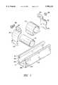
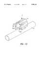
- FIG. 1is an exploded perspective view of the pipe cushion and clamp assembly of the present invention.
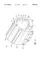
- FIG. 2is a perspective showing of the pipe cushion of FIG. 1 supported over a channel.
- FIG. 3is a perspective showing of the pipe cushion of FIG. 1.
- FIGS. 4 and 5are side and front elevational showings of the pipe cushion of FIG. 3.
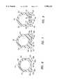
- FIGS. 6, 7 and 8are vertical cross-sectional showings of the pipe cushion of FIG. 4 taken respectively through the lines 6--6, 7--7 and 8--8 thereof.
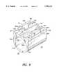
- FIG. 9is a bottom perspective showing of the pipe clamp cushion of FIG. 4.
- FIG. 10depicts installation of the present invention about a pipe.
- the preferred embodiment of the present inventionfurther includes locations along the wall of the cushion body and along the base which provides areas of raised relief for engagement with the pipe clamp elements for enhancing contact between the pipe and the pipe cushion including spaced apart groves 19a and 19b.
- the present inventionprovides a pipe cushion 10 for supporting a pipe 12 to a structural channel 14.
- Pipe cushion 10is secured to channel 14 by a two-piece pipe clamp 16.
- Channel 14 and pipe clamp 16are well known in the art and are both currently marketed by the assignee of the present invention under the trademarks KINDORF and SUPERSTRUT.
- Channel 14is an elongate U-shaped member providing a pair of transversely-spaced sidewalls 15a, 15b which define a trough 17 therebetween. The free edges of sidewalls 15a, 15b are bent over into trough 17 to form a pair of elongate retaining grooves 19.
- Pipe clamp 16includes identically-configured first clamp bracket 18 and second clamp bracket 20.
- Each clamp bracket 18, 20includes a first end, 22, 24 for retentively engaging the retaining grooves 19 of channel 14 and a second end 26, 28 for fastening engagement to the other bracket.
- Fastening devicessuch as a threaded bolt 30 and nut 32 may be used to fasten second ends 26, 28 of brackets 18, 20 to each other.
- FIGS. 3-5show pipe cushion 10 in greater detail.
- Pipe cushion 10is generally formed from flexible material such as an elastomeric polymer or soft plastic by well-known manufacturing techniques.
- Pipe cushion 10includes an elongate flexible cushion body 34 having a generally planar base 36 and a generally continuous tubular wall 38.
- Tubular wall 38includes an exterior surface 40 and a substantially cylindrical interior surface 42. Cylindrical interior surface 42 defines a longitudinal passageway 44 for accommodating pipe 12.
- Planar base 36is divided by a longitudinal slot 46 communicating with passageway 44.
- Slot 46is defined by tapering surfaces 48 and 50 which taper outwardly from passageway 44 to exterior surface 40 so as to provide a tapered lead in and to assist in deflecting base portions 36a and 36b away from each other during cushion installation over a pipe as will be discussed further hereinbelow.
- Slot 46is formed so as to substantially fully enclose pipe 12 within passageway 44.
- Pipe cushion 10preferably includes a crest rib 52 formed on exterior surface 40 at the apex, or crest 53, of cushion body 34.
- Crest rib 52is a localized region of thickness, being preferably a region of raised relief on surface 40 of tubular wall 38 and located diametrically opposite slot 46.
- Crest rib 52performs two important functions in the present invention. First, the relative thickness of crest rib 52 and the equidistant placement thereof from both planar base portions 36a and 36b ensure that tubular wall 38 deflects thereabout when pipe cushion 10 is inserted over pipe 12. Second, clamp brackets 18 and 20 will tend to ride over crest rib 52 as they are tightened about pipe cushion 10, causing crest rib 52 to deflect towards pipe 12 and to thereby provide better contact between cushion 10 and pipe 12.
- Exterior surface 40preferably also includes longitudinal side ribs 54 and longitudinal base ribs 56.
- Side ribs 54are formed on either side of cushion body 34 about midway between crest rib 52 and planar base 36.
- Base ribs 56are preferably formed on either side of cushion body 34 adjacent planar base 36. Both side ribs 54 and base ribs 56 are provided to make compressive contact between cushion body 34 and clamp brackets 18 and 20 prior to clamp brackets 18 and 20 pinching exterior surface 40 about crest 53 of pipe cushion 10. Accordingly, as clamp brackets 18 and 20 compress cushion body 34, each side rib 54 transmits the compressive force of clamp 16 towards pipe 12 prior to pipe cushion 10 being pinched and pulled about pipe 12 towards crest 53.
- base ribs 56are provided to make compressive contact between base portions 36a and 36b along slot 46 as pipe clamp brackets 18 and 20 are joined. Base ribs 56 thereby transmit the compressive clamping force prior to the development of significant pinching at the crest of pipe cushion 10 which could pull base portions 36a and 36b apart.
- Pipe cushion 10therefore conforms substantially completely about pipe 12 when secured with a two-piece clamp whereas prior art pipe cushions could be frictionally pulled towards the fastening means of such clamps.
- the pipe cushion 10 of the present inventionin providing more complete contact with pipe 12, also provides better mechanical isolation and thermal and electrical insulation of pipe 12 than is known in the prior art.
- pipe cushion 10 of the present inventionpreferably includes crest rib 52, side ribs 54, and base ribs 56, it may be appreciated that each may be provided independently of the others so as to provide compressive contact of the pipe cushion 10 about pipe 12.
- pipe cushion 10includes a pair of depending entry members 58 and 60 extending from the bottom surface 62 of planar base 36. Entry members 58 and 60 are positioned on either side of slot 46 with entry member 58 extending from base portion 62a and entry member 60 extending from base portion 62b. Entry members 58 and 60 are identically-formed members provided to extend into trough 17 of channel 14 when pipe cushion 10 is supported thereon.
- Each entry member 58, 60includes a pair of side walls 64, 66 and a backwall 68 which define an interior region 70.
- Sidewalls 64 and 66include tapered edges 65 and 67 respectively. Tapered edges 65 and 67 may be coplanar with the tapered lead into slot 46 as defined by surfaces 48 and 50.
- tapered edges 65, 67 and surfaces 48, 50should allow tapered edges 65 and 67 to make initial contact with pipe 12 being inserted into passageway 44. Furthermore, it is preferred that tapered edges make contact with pipe 12 prior to any portion of the pipe entering slot 46. The further from crest 53 that pipe 12 makes initial contact with tapered edges 65 and 67, the lower the insertion force required to open slot 46 to allow pipe 12 therethrough. Entry members 58 and 60 therefore allow for easier installation of pipe cushion 10 about pipe 12 by moving the points of initial engagement of the pipe with the cushion away from the deflection location.
- entry members 58 and 60enclose arcuate portions 62a and 62b of bottom surface 62.
- arcuate portions 62a and 62bpreferably maintain a substantially parallel alignment with cylindrical interior surface 42.
- Arcuate portions 62a and 62bthereby provide an installer more room to insert a finger into interior region 70 and manually spread planar base portions 36a and 36b apart as may be required when pipe cushion 10 is either installed over or removed from around a pipe 12.
- pipe cushion 10may be installed by placing pipe cushion 10 over pipe 12 and pushing down on pipe cushion 10 with a manual installation force F.
- installation force Fwill be transmitted through tapered edges 65 and 67 to cause planar base portions 36a and 36b to outwardly deflect away from each other.
- pipe 12travels along edges 65 and 67 towards passageway 44 to further open slot 46 until pipe 12 is able to pass therethrough and into passageway 44.
- the resilience of pipe cushion body 34ensures that planar base portions 36a and 36b return to an undeflected position whereby pipe cushion 10 engages substantially the entire circumference of a portion of pipe 12.
- entry members 58 and 60extend into trough 17 of channel 14. Bottom surface 62 of pipe cushion 10 engages the bent-over free edges of sidewall 15a and 15b of channel 14.
- entry members 58 and 60are shown located on the bottom surface of pipe cushion 10, it is contemplated by the present invention that entry members 58 and 60 could also be employed with a pipe cushion body having an entry opening in any direction so as to force the opening wider while the pipe is still positioned outside the passageway of the pipe cushion.
Landscapes
- Engineering & Computer Science (AREA)
- General Engineering & Computer Science (AREA)
- Mechanical Engineering (AREA)
- Supports For Pipes And Cables (AREA)
Abstract
Description
The present invention relates generally to a support assembly for supporting an elongate pipe to a channel member. More particularly, the present invention is directed to a pipe cushion which supports the pipe within a two-piece pipe clamp.
It is well known to support pipes and other elongate bodies with structural support channel. Pipe clamps may be used to support the pipe to the channel. Existing two-piece pipe clamp assemblies include a pair of clamp halves whereby each clamp half is positioned within the channel about the pipe and connected together using a threaded nut and bolt assembly through flanges in the clamp halves. Tightening of the nut and bolt assembly urges the clamp halves together securing the pipe to the channel.
The clamping forces employed to secure the clamp halves about the pipe may tend to bend or otherwise damage the pipe upon securing the pipe to the channel. In order to prevent such damage during securement, the art has seen the use of pipe cushions which may be positioned between the pipe and the pipe clamp.
For example U.S. Pat. No. 470,698 shows a bottom-opening pipe cushion in which the pipe is inserted through a lower slot therein. Bottom-opening pipe cushions of this type are designed for use with a single-member pipe clamp. These pipe cushions would not be suitable for use with a two-piece pipe clamp as the cushion would then exhibit a tendency to be pulled open at the insertion slot when a two-piece pipe clamp is tightened about the pipe cushion. Two-piece pipe clamps tend to pinch the bottom-opening pipe cushion body at its top surface, causing the pipe cushion body to be pulled about the surface of the pipe. The pulling of the pipe cushion body about the pipe surface results in the insertion slot being pulled open and may result in the pipe cushion body being lifted from the pipe at its top surface, resulting in further discontinuities between the pipe cushion and the inserted pipe.
In order to accommodate the use of two-piece pipe clamps, the art has developed improvements in pipe cushions. An example of an improved pipe cushion used in combination with a pipe clamp is shown in U.S. Pat. No. 4,967,148. The pipe cushion shown therein includes a generally cylindrical body formed from deformable material. The pipe is inserted into the cushion body through a slot in the upper end thereof opposite the slot. The slot divides the cushion body into two halves which must be pried open to load the pipe into the cushion. Once loaded into the cushion, the pipe clamp halves are secured about the pipe cushion to secure the pipe to the structural channel.
One disadvantage in the pipe cushions of the prior art is their failure to provide substantial continuous contact about the full circumference of an inserted pipe. United States U.S. Pat. Nos. 3,778,537 and 5,018,260 provide examples of various difference designs of such pipe cushions. Typically, the discontinuous contact is a result of an overly wide insertion slot which is too large to be closed by tightening of the clamp halves. Other times, the discontinuous contact is the result of an elongate notch provided on the interior surface of the pipe cushion so that the insertion slot may be more easily pried open for pipe insertion. The '148 patent provides an example of a pipe cushion having a weakened or open location in the pipe cushion body which facilitates flexing or deformation of the body thereabout. Constructions such as that of the '148 patent introduce a further area of discontinuity, in addition to the slotted opening, which lessens the protection to the pipe from the pipe clamp.
Another disadvantage in the pipe cushions of the prior art is the need to pry open those pipe cushions having very narrow insertion slots. Pipe cushions attempting to maximize the amount of contact between the pipe cushion and the inserted pipe can be cumbersome to install as they require greater deflection when receiving a pipe therein.
It is therefore desirable to provide an improved pipe cushion for use in a support assembly which may be easily fitted onto the pipe and which provides substantially continuous protective support of the pipe between the structural channel and the pipe clamp assembly.
It is an object of the present invention to provide a support assembly for supporting an elongate pipe to a channel member.
It is further object the present invention to provide a pipe cushion which supports and protects a pipe against a channel member and which is secured to the channel member by a pipe clamp.
It is another object of the present invention to provide a pipe cushion which is easily attachable to a pipe.
It is yet another object of the present invention to provide a bottom-opening pipe cushion providing substantially continuous contact about a pipe.
In the efficient attainment of these and other objects, the present invention provides an assembly for supporting a pipe to a structural channel. The assembly includes a pipe cushion including a deformable cushion body having a base for positioning on the structural channel. The base includes a slot therethrough. The pipe cushion body includes a continuous tubular wall extending from the base and being divided by the slot. The tubular wall forms a pipe supporting passageway therethrough. The slot in the base is in communication with the passageway for permitting insertion of the pipe therein to. A pair of pipe clamp elements are employed which include a first end attachable to the channel and an opposed second end for mutual connection about the pipe cushion. The second ends of the pipe clamp elements are connectable adjacent a crest of the pipe cushion body which is spaced from the slot.
The present invention also provides a pipe cushion body having a tapered lead into the slot as well as entry facilitating members to force the slot open prior to the pipe entering the slot so as to facilitate insertion of the pipe therethrough and into the passageway.
The present invention also provides an area of increased thickness on the crest of the body so as to resist separation from the pipe surface thereabout, upon attachment of the pipe clamps about the pipe cushion. The pipe cushion body is deformable about the crest so as to admit the pipe into the passageway.
FIG. 1 is an exploded perspective view of the pipe cushion and clamp assembly of the present invention.
FIG. 2 is a perspective showing of the pipe cushion of FIG. 1 supported over a channel.
FIG. 3 is a perspective showing of the pipe cushion of FIG. 1.
FIGS. 4 and 5 are side and front elevational showings of the pipe cushion of FIG. 3.
FIGS. 6, 7 and 8 are vertical cross-sectional showings of the pipe cushion of FIG. 4 taken respectively through thelines 6--6, 7--7 and 8--8 thereof.
FIG. 9 is a bottom perspective showing of the pipe clamp cushion of FIG. 4.
FIG. 10 depicts installation of the present invention about a pipe.
The preferred embodiment of the present invention further includes locations along the wall of the cushion body and along the base which provides areas of raised relief for engagement with the pipe clamp elements for enhancing contact between the pipe and the pipe cushion including spaced apartgroves
With reference to FIGS. 1 and 2, the present invention provides apipe cushion 10 for supporting apipe 12 to astructural channel 14.Pipe cushion 10 is secured tochannel 14 by a two-piece pipe clamp 16.
Channel 14 andpipe clamp 16 are well known in the art and are both currently marketed by the assignee of the present invention under the trademarks KINDORF and SUPERSTRUT. Channel 14 is an elongate U-shaped member providing a pair of transversely-spacedsidewalls trough 17 therebetween. The free edges ofsidewalls trough 17 to form a pair of elongateretaining grooves 19.Pipe clamp 16 includes identically-configuredfirst clamp bracket 18 andsecond clamp bracket 20. Eachclamp bracket grooves 19 ofchannel 14 and asecond end bolt 30 andnut 32 may be used to fasten second ends 26, 28 ofbrackets
FIGS. 3-5show pipe cushion 10 in greater detail.Pipe cushion 10 is generally formed from flexible material such as an elastomeric polymer or soft plastic by well-known manufacturing techniques.Pipe cushion 10 includes an elongateflexible cushion body 34 having a generallyplanar base 36 and a generally continuoustubular wall 38.Tubular wall 38 includes anexterior surface 40 and a substantially cylindricalinterior surface 42. Cylindricalinterior surface 42 defines alongitudinal passageway 44 for accommodatingpipe 12.
Whilepipe cushion 10 of the present invention preferably includescrest rib 52,side ribs 54, andbase ribs 56, it may be appreciated that each may be provided independently of the others so as to provide compressive contact of thepipe cushion 10 aboutpipe 12.
As shown in FIGS. 6-9,pipe cushion 10 includes a pair of dependingentry members planar base 36.Entry members slot 46 withentry member 58 extending frombase portion 62a andentry member 60 extending frombase portion 62b.Entry members trough 17 ofchannel 14 whenpipe cushion 10 is supported thereon. Eachentry member side walls backwall 68 which define aninterior region 70. Sidewalls 64 and 66 include taperededges slot 46 as defined bysurfaces edges edges pipe 12 being inserted intopassageway 44. Furthermore, it is preferred that tapered edges make contact withpipe 12 prior to any portion of thepipe entering slot 46. The further fromcrest 53 thatpipe 12 makes initial contact with taperededges slot 46 to allowpipe 12 therethrough.Entry members pipe cushion 10 aboutpipe 12 by moving the points of initial engagement of the pipe with the cushion away from the deflection location.
Withininterior region 70,entry members arcuate portions arcuate portions interior surface 42.Arcuate portions interior region 70 and manually spreadplanar base portions pipe cushion 10 is either installed over or removed from around apipe 12.
With reference to FIG. 10,pipe cushion 10 may be installed by placingpipe cushion 10 overpipe 12 and pushing down onpipe cushion 10 with a manual installation force F. Aspipe 12 makes initial contact with taperededges entry members edges planar base portions pipe 12 travels alongedges passageway 44 to furtheropen slot 46 untilpipe 12 is able to pass therethrough and intopassageway 44. Once fully inserted intopassageway 44, the resilience ofpipe cushion body 34 ensures thatplanar base portions pipe cushion 10 engages substantially the entire circumference of a portion ofpipe 12. Furthermore, and referring again to FIGS. 1 and 2,entry members trough 17 ofchannel 14. Bottom surface 62 ofpipe cushion 10 engages the bent-over free edges ofsidewall channel 14.
Whileentry members pipe cushion 10, it is contemplated by the present invention thatentry members
While the particular embodiment of the present invention has been shown and described, it will be obvious to those skilled in the art that changes and modifications may be made without departing from the teachings of the invention. The matter set forth in the foregoing description and accompanying drawings is offered by way of illustration only and not as a limitation. The actual scope of the invention is intended to be defined in the following claims when viewed in their proper perspective based on the prior art.
Claims (19)
1. An assembly for supporting a pipe to a structural support channel, comprising:
a pipe cushion including a deformable pipe cushion body having a base for positioning over said structural support channel, said base having a slot therethrough;
said body including a continuous tubular wall extending upwardly from said base and being divided by said slot, said tubular wall forming a pipe supporting passageway through said body, said tubular wall conforming substantially fully about a pipe inserted into said passageway, said slot being in communication with said passageway for permitting insertion of said pipe therein, said body further including a crest spaced from said slot, said crest including a crest rib; and
a pair of pipe clamp elements, said pipe clamp elements having a first end attachable to said channel and a second end for mutual connection, about said pipe cushion;
said second ends of said pipe clamp elements being connectable at said crest rib for urging said body into compression about said pipe.
2. An assembly of claim 1 wherein said base of said pipe cushion body includes a tapered lead-in portion about said slot for facilitating said passage of said pipe therethrough.
3. An assembly of claim 1 wherein said body is generally cylindrical and wherein said pipe cushion body includes said crest diametrically opposed to said slot.
4. An assembly of claim 3 wherein said body is deformable about said crest.
5. An assembly of claim 4 wherein said pair of pipe clamp element second ends include connection flanges which are connectable to one another so as to secure said pipe cushion to said channel.
6. An assembly of claim 5 where said pipe clamp elements conform generally to said shape of said cushion body.
7. An assembly of claim 6 where said crest rib includes an area of increased thickness of said tubular wall.
8. An assembly of claim 6 where said crest rib includes an area of raised relief.
9. An assembly of claim 8 where said tubular wall includes a pair of lateral localities of raised relief for engagement by said pipe clamp elements.
10. An assembly of claim 1, wherein said cushion body further includes a pair of entry members located to either side of and spaced from said slot, said entry members providing a tapered lead-in into said slot so as to expand said slot upon said entry members making contact with said pipe being inserted into said passageway of said cushion body.
11. A pipe cushion for supporting a pipe to a structural channel having a pair of elongate adjustably coupled pipe clamp elements, said pipe clamp elements being positionable about said pipe and mutually connectable to each other, said pipe cushion comprising:
an elongate deformable cushion body for positioning on said structural channel, said body having a generally continuous tubular wall including a base and defining a central passageway through, said tubular wall having a slot through said base in communication with passageway for passage of said pipe therethrough, and for fully encompassing said pipe inserted into said passageway;
said continuous wall defining a pair of spaced apart base ribs having raised relief and being engageable with said clamp elements for forcing said tubular wall in substantial conformance with said pipe.
12. A pipe cushion of claim 11 wherein said tubular wall includes an outwardly directed crest diametrically opposed from said slot.
13. A pipe cushion of claim 12 wherein said crest includes an area of increased wall thickness.
14. A pipe cushion of claim 12 wherein said cushion body is generally deformable about said crest.
15. A pipe cushion of claim 11, wherein said cushion body further includes a pair of side ribs having raised relief located between said crest and said planar base, said pair of side ribs provided to engage said pipe clamp.
16. A pipe cushion of claim 11, wherein said cushion body further includes a pair of entry members located to either side of said slot, said entry members providing a tapered lead-in into said slot for expanding said slot upon said entry members making contact with said pipe and prior to said pipe being inserted into said passageway of said cushion body.
17. A pipe cushion for supporting a pipe to a structural channel, said pipe cushion comprising:
an elongate deformable cushion body having a base and a longitudinal slot through said base;
said body including a tubular wall extending from one side of said slot to the other side of said slot and defining a central passageway through said body, said passageway being in communication with said slot for passage of said pipe into said passageway;
said cushion body further including a pair of entry members located to either side of and spaced from said slot, said entry members providing having opposed inclined side wall surfaces extending from an external surface of said tubular wall inwardly towards said passages and a tapered lead-in into said slot so as to expand said slot upon said entry members making contact with said pipe and prior to said pipe being inserted into said passageway of said cushion body.
18. A pipe cushion of claim 17 wherein said cushion body further includes a base for placement against said structural channel.
19. A pipe cushion of claim 18 wherein said slot extends through said base.
Priority Applications (2)
| Application Number | Priority Date | Filing Date | Title |
|---|---|---|---|
| US08/926,216US5984243A (en) | 1997-09-09 | 1997-09-09 | Pipe cushion |
| CA002250418ACA2250418C (en) | 1997-09-09 | 1998-10-13 | Pipe cushion |
Applications Claiming Priority (2)
| Application Number | Priority Date | Filing Date | Title |
|---|---|---|---|
| US08/926,216US5984243A (en) | 1997-09-09 | 1997-09-09 | Pipe cushion |
| CA002250418ACA2250418C (en) | 1997-09-09 | 1998-10-13 | Pipe cushion |
Publications (1)
| Publication Number | Publication Date |
|---|---|
| US5984243Atrue US5984243A (en) | 1999-11-16 |
Family
ID=31994814
Family Applications (1)
| Application Number | Title | Priority Date | Filing Date |
|---|---|---|---|
| US08/926,216Expired - LifetimeUS5984243A (en) | 1997-09-09 | 1997-09-09 | Pipe cushion |
Country Status (2)
| Country | Link |
|---|---|
| US (1) | US5984243A (en) |
| CA (1) | CA2250418C (en) |
Cited By (54)
| Publication number | Priority date | Publication date | Assignee | Title |
|---|---|---|---|---|
| US6364262B1 (en)* | 1999-10-01 | 2002-04-02 | Burke Gibson, Inc. | Display assembly |
| US6464180B2 (en) | 2000-06-22 | 2002-10-15 | 3 North Technologies, Llc | Pipe attaching apparatus |
| US6575412B2 (en)* | 2000-09-11 | 2003-06-10 | Kaefer Isoliertechnik Gmbh & Co. Kg | Support for pipelines and process for mounting such a support |
| US20040037997A1 (en)* | 2001-04-26 | 2004-02-26 | Pipe Pier | Mounting device |
| US6799607B1 (en) | 2003-06-18 | 2004-10-05 | Pbm, Inc. | Sanitary conduit support systems and methods |
| USD499957S1 (en) | 2003-06-18 | 2004-12-21 | Pbm, Inc. | Conduit support |
| US20050005982A1 (en)* | 2003-07-10 | 2005-01-13 | Brian Muscat | Power steering noise and vibration attenuator |
| US20050109887A1 (en)* | 2003-11-26 | 2005-05-26 | Catapano Joseph P. | Cable holder |
| US20050163561A1 (en)* | 2004-01-23 | 2005-07-28 | Weger Kris A. | Adjustable pipe clamp assembly |
| USD513168S1 (en)* | 2001-11-28 | 2005-12-27 | Chun-Chung Chu | U-clamp for hose fittings |
| US20060091265A1 (en)* | 2004-10-28 | 2006-05-04 | Freedom, Inc. | Support block system |
| USD538148S1 (en)* | 2005-07-29 | 2007-03-13 | Thomas & Betts International, Inc. | Pipe clamp |
| US20070057125A1 (en)* | 2001-04-26 | 2007-03-15 | Hawkins Patrick A | Mounting device |
| US20080053506A1 (en)* | 2006-03-20 | 2008-03-06 | Richard Dreamwalker | Pole brace and ballasting device |
| US7475862B1 (en)* | 2006-01-23 | 2009-01-13 | Anspach Gary D | Stub steel holder |
| USD682463S1 (en)* | 2012-03-06 | 2013-05-14 | Easton O. Bernard | Track lighting hanging bracket |
| US20140097304A1 (en)* | 2012-10-10 | 2014-04-10 | Ronald J. Mastro | Slanted bolstering device for pipe support system |
| GB2514242A (en)* | 2013-03-15 | 2014-11-19 | Zsi Inc | Cushion insert for a tubing clamp and method of replacement |
| USD728753S1 (en)* | 2013-01-16 | 2015-05-05 | Susumu Hikoyama | Angled pipe clamp |
| US20150204474A1 (en)* | 2014-01-23 | 2015-07-23 | Hans-Jurgen Guido | After the mass-spring principle operating vibration absorber |
| USD735025S1 (en)* | 2014-01-28 | 2015-07-28 | Behringer Corporation | Hygienic clamp |
| US20150217154A1 (en)* | 2014-02-06 | 2015-08-06 | Performance Advantage Company, Inc. | Universal nozzle connector with an adjustable mount |
| US20150316178A1 (en)* | 2014-05-02 | 2015-11-05 | Cooper Technologies Company | Conduit clamp for strut channel |
| USD747181S1 (en)* | 2013-01-16 | 2016-01-12 | Susumu Hikoyama | Angled pipe clamp |
| US9347213B1 (en) | 2014-11-14 | 2016-05-24 | Cooper Technologies Company | Fitting for channel framing |
| US9347589B1 (en)* | 2008-10-22 | 2016-05-24 | Lawrence S. Cohen | Strut clamp |
| US9453592B2 (en) | 2013-03-14 | 2016-09-27 | Cooper Technologies Company | Fitting including clip for channel framing |
| US9458952B2 (en) | 2014-04-30 | 2016-10-04 | Cooper Technologies Company | Trapeze hanger system including twist-locking fitting |
| US20170036246A1 (en)* | 2015-03-26 | 2017-02-09 | Boe Technology Group Co., Ltd. | Cleaning system for photovoltaic power station |
| US9574589B2 (en) | 2014-04-30 | 2017-02-21 | Cooper Technologies Company | Trapeze hanger system including trapeze hanger fitting |
| JP2017057912A (en)* | 2015-09-16 | 2017-03-23 | パナソニックIpマネジメント株式会社 | Piping fixture |
| US9683590B2 (en) | 2014-05-02 | 2017-06-20 | Cooper Technologies Company | Strut system and strut fitting therefor |
| US9790980B2 (en) | 2013-12-23 | 2017-10-17 | Cooper Technologies Company | Fastener nut for channel framing |
| US9903512B2 (en)* | 2015-05-26 | 2018-02-27 | Georg Fischer Llc | Pipe clamp for strut system |
| USD813660S1 (en)* | 2009-12-30 | 2018-03-27 | Cnd Products Llc | Canister holder |
| US9926957B2 (en) | 2014-11-14 | 2018-03-27 | Cooper Technologies Company | Fitting for strut channel |
| US9982695B2 (en) | 2014-11-14 | 2018-05-29 | Cooper Technologies Company | Fitting for strut channel |
| USD825488S1 (en)* | 2014-06-17 | 2018-08-14 | Japan Aviation Electronics Industry, Limited | Cap for optical connector |
| US20180245716A1 (en)* | 2015-09-07 | 2018-08-30 | J. Van Walraven Holding B.V. | Conduit clip |
| US10100861B2 (en) | 2014-11-14 | 2018-10-16 | Cooper Technologies Company | Beam clamp for strut channel |
| US10100950B2 (en)* | 2015-02-13 | 2018-10-16 | J. Van Walraven Holding B.V. | Pipe clamp |
| USD843199S1 (en)* | 2018-06-20 | 2019-03-19 | Wild West Investments, LLC | Adaptor rail for supporting an electronic device |
| US10294675B2 (en)* | 2016-11-10 | 2019-05-21 | Hunter Douglas Industries B.V. | Bracket for mounting a panel to a carrier |
| US10320173B2 (en)* | 2017-03-28 | 2019-06-11 | Atkore Steel Components, Inc. | Conduit support assembly |
| US10415724B2 (en)* | 2016-07-13 | 2019-09-17 | Paul Brett Wegner | Strut clip |
| US10947724B2 (en) | 2018-07-04 | 2021-03-16 | Hunter Douglas Industries B.V. | Ceiling system |
| US11009153B1 (en)* | 2019-11-18 | 2021-05-18 | Atsushi Hikoyama | Angle strut strap |
| US11274774B2 (en)* | 2013-04-12 | 2022-03-15 | Eric Stechmann | Strut bracket for magnetically mounting hardware to a structure |
| US11572021B2 (en) | 2020-01-31 | 2023-02-07 | Wild West Investments, LLC | Vehicular mounted rail system |
| US11746808B2 (en) | 2013-04-12 | 2023-09-05 | Eric Stechmann | Apparatus and system for securing hardware to a structure utilizing torsional joints |
| US12115919B2 (en) | 2022-10-14 | 2024-10-15 | Yonder Fund Llc | Mounting system with anti-rotation features for supporting an electronic device |
| USD1064795S1 (en)* | 2022-12-16 | 2025-03-04 | Takeyah Holder | Hose holder |
| USD1085851S1 (en)* | 2023-10-09 | 2025-07-29 | Kevin Andrew Holder | Tubing holder |
| US12388199B1 (en)* | 2023-01-12 | 2025-08-12 | Edel Deniz | Electrical conduit clamp |
Citations (37)
| Publication number | Priority date | Publication date | Assignee | Title |
|---|---|---|---|---|
| US470698A (en)* | 1892-03-15 | Plumber s fastening-strap for lead pipes | ||
| US2399899A (en)* | 1944-04-10 | 1946-05-07 | Tinnerman Products Inc | Bonding clamp |
| US2440469A (en)* | 1944-10-23 | 1948-04-27 | Adel Prec Products Corp | Multiple clip and bracket |
| US2761714A (en)* | 1950-08-12 | 1956-09-04 | Chrysler Corp | Mounting device |
| US2872141A (en)* | 1953-11-27 | 1959-02-03 | Gen Motors Corp | Cable hanger |
| US2998228A (en)* | 1956-11-23 | 1961-08-29 | Huet Andre | Surface heat exchangers |
| US3154281A (en)* | 1962-02-20 | 1964-10-27 | Frank Charles | Holder for electronic components |
| US3203653A (en)* | 1963-02-18 | 1965-08-31 | Glenn R Hall | Insulators for fixtures |
| US3341231A (en)* | 1966-03-11 | 1967-09-12 | Johanson Lars | Oil tube holding chuck |
| US3370815A (en)* | 1965-09-13 | 1968-02-27 | Lamb Co F Jos | Shock absorbing pad for conduit clamping device |
| US3397431A (en)* | 1967-05-12 | 1968-08-20 | Hydro Craft Inc | Tube clamp assembly |
| US3414220A (en)* | 1966-12-30 | 1968-12-03 | Hydro Craft Inc | Clamp means |
| US3429014A (en)* | 1967-12-04 | 1969-02-25 | Castle Ind Inc Of California | Clamp assembly for confronting annular flanges |
| US3486726A (en)* | 1968-07-09 | 1969-12-30 | Robert D Kindorf | Universal pipe clamp |
| US3521842A (en)* | 1968-05-06 | 1970-07-28 | Lamb Co F Jos | Spring clamp for mounting conduit on a channel support |
| US3606218A (en)* | 1969-03-21 | 1971-09-20 | Gen Dynamics Corp | Sound and vibration isolation support |
| US3684223A (en)* | 1970-10-20 | 1972-08-15 | Duane D Logsdon | Pipe clamp |
| US3778537A (en)* | 1973-01-05 | 1973-12-11 | Antennacraft Co | Clip device for mounting accessory on an antenna boom |
| US3843083A (en)* | 1972-11-09 | 1974-10-22 | Wonder Piles | Mounting apparatus for portable device |
| US3848839A (en)* | 1972-01-25 | 1974-11-19 | G Tillman | Conduit support clamp |
| US4037810A (en)* | 1976-01-12 | 1977-07-26 | Indian Head Inc. | Pipe bracket and clamp |
| US4185802A (en)* | 1978-09-13 | 1980-01-29 | Fischer Sherman, Inc. | Anti-vibration pad for pipe support clamp |
| US4213589A (en)* | 1977-09-08 | 1980-07-22 | A. Raymond | Clamp for securing round articles |
| US4417755A (en)* | 1974-10-07 | 1983-11-29 | Familian Corp. | Pipe coupling |
| US4442994A (en)* | 1982-02-02 | 1984-04-17 | Logsdon Duane D | Pipe hanger capable of totally encircling a pipe |
| US4470179A (en)* | 1982-04-22 | 1984-09-11 | A. Raymond | Fastener-clip |
| US4516296A (en)* | 1983-10-05 | 1985-05-14 | Zsi, Inc. | Tubing clamp and method of making the same |
| US4612680A (en)* | 1984-03-26 | 1986-09-23 | Harumoto Iron Works Co., Ltd. | Cover joint and armor for bridge cable |
| US4614321A (en)* | 1984-04-30 | 1986-09-30 | A. Raymond | Pipe clip |
| US4640479A (en)* | 1983-01-31 | 1987-02-03 | All States Inc. | Strain relief grommet |
| US4653782A (en)* | 1985-02-18 | 1987-03-31 | British Gas Corporation | Pipe repair clamp |
| US4934635A (en)* | 1988-12-20 | 1990-06-19 | Zsi, Inc. | Tubing clamp with hinged cushion |
| US4997148A (en)* | 1988-12-20 | 1991-03-05 | Zsi, Inc. | Tubing clamp with hinged cushion |
| US5013002A (en)* | 1990-04-16 | 1991-05-07 | The Pullman Company | Elastomeric clamp |
| US5013166A (en)* | 1989-01-31 | 1991-05-07 | Hutchinson | Torsion bar bearing |
| US5018260A (en)* | 1989-05-26 | 1991-05-28 | Asahi/America, Inc. | Supports for double-containment thermoplastic pipe assemblies |
| US5547152A (en)* | 1994-12-09 | 1996-08-20 | Connection Systems Group | Pipe mounting bracket |
- 1997
- 1997-09-09USUS08/926,216patent/US5984243A/ennot_activeExpired - Lifetime
- 1998
- 1998-10-13CACA002250418Apatent/CA2250418C/ennot_activeExpired - Lifetime
Patent Citations (37)
| Publication number | Priority date | Publication date | Assignee | Title |
|---|---|---|---|---|
| US470698A (en)* | 1892-03-15 | Plumber s fastening-strap for lead pipes | ||
| US2399899A (en)* | 1944-04-10 | 1946-05-07 | Tinnerman Products Inc | Bonding clamp |
| US2440469A (en)* | 1944-10-23 | 1948-04-27 | Adel Prec Products Corp | Multiple clip and bracket |
| US2761714A (en)* | 1950-08-12 | 1956-09-04 | Chrysler Corp | Mounting device |
| US2872141A (en)* | 1953-11-27 | 1959-02-03 | Gen Motors Corp | Cable hanger |
| US2998228A (en)* | 1956-11-23 | 1961-08-29 | Huet Andre | Surface heat exchangers |
| US3154281A (en)* | 1962-02-20 | 1964-10-27 | Frank Charles | Holder for electronic components |
| US3203653A (en)* | 1963-02-18 | 1965-08-31 | Glenn R Hall | Insulators for fixtures |
| US3370815A (en)* | 1965-09-13 | 1968-02-27 | Lamb Co F Jos | Shock absorbing pad for conduit clamping device |
| US3341231A (en)* | 1966-03-11 | 1967-09-12 | Johanson Lars | Oil tube holding chuck |
| US3414220A (en)* | 1966-12-30 | 1968-12-03 | Hydro Craft Inc | Clamp means |
| US3397431A (en)* | 1967-05-12 | 1968-08-20 | Hydro Craft Inc | Tube clamp assembly |
| US3429014A (en)* | 1967-12-04 | 1969-02-25 | Castle Ind Inc Of California | Clamp assembly for confronting annular flanges |
| US3521842A (en)* | 1968-05-06 | 1970-07-28 | Lamb Co F Jos | Spring clamp for mounting conduit on a channel support |
| US3486726A (en)* | 1968-07-09 | 1969-12-30 | Robert D Kindorf | Universal pipe clamp |
| US3606218A (en)* | 1969-03-21 | 1971-09-20 | Gen Dynamics Corp | Sound and vibration isolation support |
| US3684223A (en)* | 1970-10-20 | 1972-08-15 | Duane D Logsdon | Pipe clamp |
| US3848839A (en)* | 1972-01-25 | 1974-11-19 | G Tillman | Conduit support clamp |
| US3843083A (en)* | 1972-11-09 | 1974-10-22 | Wonder Piles | Mounting apparatus for portable device |
| US3778537A (en)* | 1973-01-05 | 1973-12-11 | Antennacraft Co | Clip device for mounting accessory on an antenna boom |
| US4417755A (en)* | 1974-10-07 | 1983-11-29 | Familian Corp. | Pipe coupling |
| US4037810A (en)* | 1976-01-12 | 1977-07-26 | Indian Head Inc. | Pipe bracket and clamp |
| US4213589A (en)* | 1977-09-08 | 1980-07-22 | A. Raymond | Clamp for securing round articles |
| US4185802A (en)* | 1978-09-13 | 1980-01-29 | Fischer Sherman, Inc. | Anti-vibration pad for pipe support clamp |
| US4442994A (en)* | 1982-02-02 | 1984-04-17 | Logsdon Duane D | Pipe hanger capable of totally encircling a pipe |
| US4470179A (en)* | 1982-04-22 | 1984-09-11 | A. Raymond | Fastener-clip |
| US4640479A (en)* | 1983-01-31 | 1987-02-03 | All States Inc. | Strain relief grommet |
| US4516296A (en)* | 1983-10-05 | 1985-05-14 | Zsi, Inc. | Tubing clamp and method of making the same |
| US4612680A (en)* | 1984-03-26 | 1986-09-23 | Harumoto Iron Works Co., Ltd. | Cover joint and armor for bridge cable |
| US4614321A (en)* | 1984-04-30 | 1986-09-30 | A. Raymond | Pipe clip |
| US4653782A (en)* | 1985-02-18 | 1987-03-31 | British Gas Corporation | Pipe repair clamp |
| US4934635A (en)* | 1988-12-20 | 1990-06-19 | Zsi, Inc. | Tubing clamp with hinged cushion |
| US4997148A (en)* | 1988-12-20 | 1991-03-05 | Zsi, Inc. | Tubing clamp with hinged cushion |
| US5013166A (en)* | 1989-01-31 | 1991-05-07 | Hutchinson | Torsion bar bearing |
| US5018260A (en)* | 1989-05-26 | 1991-05-28 | Asahi/America, Inc. | Supports for double-containment thermoplastic pipe assemblies |
| US5013002A (en)* | 1990-04-16 | 1991-05-07 | The Pullman Company | Elastomeric clamp |
| US5547152A (en)* | 1994-12-09 | 1996-08-20 | Connection Systems Group | Pipe mounting bracket |
Cited By (94)
| Publication number | Priority date | Publication date | Assignee | Title |
|---|---|---|---|---|
| US6364262B1 (en)* | 1999-10-01 | 2002-04-02 | Burke Gibson, Inc. | Display assembly |
| US6464180B2 (en) | 2000-06-22 | 2002-10-15 | 3 North Technologies, Llc | Pipe attaching apparatus |
| US6575412B2 (en)* | 2000-09-11 | 2003-06-10 | Kaefer Isoliertechnik Gmbh & Co. Kg | Support for pipelines and process for mounting such a support |
| US20040037997A1 (en)* | 2001-04-26 | 2004-02-26 | Pipe Pier | Mounting device |
| US20070057125A1 (en)* | 2001-04-26 | 2007-03-15 | Hawkins Patrick A | Mounting device |
| US7708235B2 (en)* | 2001-04-26 | 2010-05-04 | Pipe Pier | Mounting device |
| US20100258700A1 (en)* | 2001-04-26 | 2010-10-14 | Pipe Pier | Mounting device |
| US7922130B2 (en)* | 2001-04-26 | 2011-04-12 | Pipe Pier | Mounting device |
| USD513168S1 (en)* | 2001-11-28 | 2005-12-27 | Chun-Chung Chu | U-clamp for hose fittings |
| USD499957S1 (en) | 2003-06-18 | 2004-12-21 | Pbm, Inc. | Conduit support |
| USD516416S1 (en) | 2003-06-18 | 2006-03-07 | Pbm, Inc. | Conduit support |
| USD516415S1 (en) | 2003-06-18 | 2006-03-07 | Pbm, Inc. | Conduit support |
| USD516903S1 (en) | 2003-06-18 | 2006-03-14 | Pbm, Inc. | Conduit support |
| US7367363B2 (en) | 2003-06-18 | 2008-05-06 | Pbm, Inc. | Sanitary conduit support systems |
| US7543606B2 (en) | 2003-06-18 | 2009-06-09 | Stauff Corporation | Methods for supporting conduits in a sanitary environment |
| US6799607B1 (en) | 2003-06-18 | 2004-10-05 | Pbm, Inc. | Sanitary conduit support systems and methods |
| US7195038B2 (en) | 2003-06-18 | 2007-03-27 | Pbm, Inc. | Conduit supports |
| US7481247B2 (en) | 2003-06-18 | 2009-01-27 | Stauff Corporation | Sanitary conduit supports |
| US7059353B2 (en)* | 2003-07-10 | 2006-06-13 | Daimlerchrysler Corporation | Power steering noise and vibration attenuator |
| US20050005982A1 (en)* | 2003-07-10 | 2005-01-13 | Brian Muscat | Power steering noise and vibration attenuator |
| US20050109887A1 (en)* | 2003-11-26 | 2005-05-26 | Catapano Joseph P. | Cable holder |
| US7293745B2 (en)* | 2003-11-26 | 2007-11-13 | Site Pro 1, Inc. | Cable holder |
| US7179010B2 (en) | 2004-01-23 | 2007-02-20 | Zsi, Inc. | Adjustable pipe clamp assembly |
| US20070034752A1 (en)* | 2004-01-23 | 2007-02-15 | Zsi, Inc. | Adjustable pipe clamp assembly |
| US20050163561A1 (en)* | 2004-01-23 | 2005-07-28 | Weger Kris A. | Adjustable pipe clamp assembly |
| US7441731B2 (en)* | 2004-10-28 | 2008-10-28 | Smart Kenneth L | Support block system |
| US20060091265A1 (en)* | 2004-10-28 | 2006-05-04 | Freedom, Inc. | Support block system |
| USD538148S1 (en)* | 2005-07-29 | 2007-03-13 | Thomas & Betts International, Inc. | Pipe clamp |
| US7475862B1 (en)* | 2006-01-23 | 2009-01-13 | Anspach Gary D | Stub steel holder |
| US20080053506A1 (en)* | 2006-03-20 | 2008-03-06 | Richard Dreamwalker | Pole brace and ballasting device |
| US9347589B1 (en)* | 2008-10-22 | 2016-05-24 | Lawrence S. Cohen | Strut clamp |
| USD813660S1 (en)* | 2009-12-30 | 2018-03-27 | Cnd Products Llc | Canister holder |
| USD682463S1 (en)* | 2012-03-06 | 2013-05-14 | Easton O. Bernard | Track lighting hanging bracket |
| US20140097304A1 (en)* | 2012-10-10 | 2014-04-10 | Ronald J. Mastro | Slanted bolstering device for pipe support system |
| USD747181S1 (en)* | 2013-01-16 | 2016-01-12 | Susumu Hikoyama | Angled pipe clamp |
| USD728753S1 (en)* | 2013-01-16 | 2015-05-05 | Susumu Hikoyama | Angled pipe clamp |
| US9470339B2 (en) | 2013-03-14 | 2016-10-18 | Cooper Technologies Company | Fitting for connecting two pieces of channel framing to one another |
| US9982837B2 (en) | 2013-03-14 | 2018-05-29 | Cooper Technologies Company | Fitting including clip for channel framing |
| US10619791B2 (en) | 2013-03-14 | 2020-04-14 | Eaton Intelligent Power Limited | Channel framing with additional functional side |
| US9746105B2 (en) | 2013-03-14 | 2017-08-29 | Cooper Technologies Company | Conduit clamp for channel framing |
| US9651171B2 (en) | 2013-03-14 | 2017-05-16 | Cooper Technologies Company | Nut-washer assembly for channel framing |
| US9587767B2 (en) | 2013-03-14 | 2017-03-07 | Cooper Technology Company | Fitting for trapeze hanger |
| US9453592B2 (en) | 2013-03-14 | 2016-09-27 | Cooper Technologies Company | Fitting including clip for channel framing |
| GB2514242A (en)* | 2013-03-15 | 2014-11-19 | Zsi Inc | Cushion insert for a tubing clamp and method of replacement |
| GB2514242B (en)* | 2013-03-15 | 2020-02-19 | Zsi Foster Inc | Cushion insert for a tubing clamp and method of replacement |
| US11274774B2 (en)* | 2013-04-12 | 2022-03-15 | Eric Stechmann | Strut bracket for magnetically mounting hardware to a structure |
| US11746808B2 (en) | 2013-04-12 | 2023-09-05 | Eric Stechmann | Apparatus and system for securing hardware to a structure utilizing torsional joints |
| US9790980B2 (en) | 2013-12-23 | 2017-10-17 | Cooper Technologies Company | Fastener nut for channel framing |
| US20150204474A1 (en)* | 2014-01-23 | 2015-07-23 | Hans-Jurgen Guido | After the mass-spring principle operating vibration absorber |
| US10203060B2 (en)* | 2014-01-23 | 2019-02-12 | Hans-Jurgen Guido | After the mass-spring principle operating vibration absorber |
| USD735025S1 (en)* | 2014-01-28 | 2015-07-28 | Behringer Corporation | Hygienic clamp |
| US20150217154A1 (en)* | 2014-02-06 | 2015-08-06 | Performance Advantage Company, Inc. | Universal nozzle connector with an adjustable mount |
| US10751558B2 (en) | 2014-02-06 | 2020-08-25 | Performance Advantage Company, Inc. | Universal nozzle connector with an adjustable mount |
| US9732887B2 (en) | 2014-04-30 | 2017-08-15 | Cooper Technologies Company | Trapeze hanger system including twist-locking fitting |
| US9458952B2 (en) | 2014-04-30 | 2016-10-04 | Cooper Technologies Company | Trapeze hanger system including twist-locking fitting |
| US9574589B2 (en) | 2014-04-30 | 2017-02-21 | Cooper Technologies Company | Trapeze hanger system including trapeze hanger fitting |
| US10012255B2 (en) | 2014-04-30 | 2018-07-03 | Cooper Technologies Company | Trapeze hanger system including trapeze hanger fitting |
| US9546744B2 (en)* | 2014-05-02 | 2017-01-17 | Cooper Technologies Company | Conduit clamp for strut channel |
| US9683590B2 (en) | 2014-05-02 | 2017-06-20 | Cooper Technologies Company | Strut system and strut fitting therefor |
| US20150316178A1 (en)* | 2014-05-02 | 2015-11-05 | Cooper Technologies Company | Conduit clamp for strut channel |
| US9989169B2 (en) | 2014-05-02 | 2018-06-05 | Cooper Technologies Company | Conduit clamp for strut channel |
| USD825488S1 (en)* | 2014-06-17 | 2018-08-14 | Japan Aviation Electronics Industry, Limited | Cap for optical connector |
| US9580900B2 (en) | 2014-11-14 | 2017-02-28 | Cooper Technologies Company | Fitting for channel framing |
| US9926957B2 (en) | 2014-11-14 | 2018-03-27 | Cooper Technologies Company | Fitting for strut channel |
| US10100861B2 (en) | 2014-11-14 | 2018-10-16 | Cooper Technologies Company | Beam clamp for strut channel |
| US10161127B2 (en) | 2014-11-14 | 2018-12-25 | Cooper Technologies Company | Fitting for channel framing |
| US9982695B2 (en) | 2014-11-14 | 2018-05-29 | Cooper Technologies Company | Fitting for strut channel |
| US9347213B1 (en) | 2014-11-14 | 2016-05-24 | Cooper Technologies Company | Fitting for channel framing |
| US10100950B2 (en)* | 2015-02-13 | 2018-10-16 | J. Van Walraven Holding B.V. | Pipe clamp |
| AU2016218510B2 (en)* | 2015-02-13 | 2020-07-30 | J. Van Walraven Holding B.V. | Pipe clamp |
| US20170036246A1 (en)* | 2015-03-26 | 2017-02-09 | Boe Technology Group Co., Ltd. | Cleaning system for photovoltaic power station |
| US9903512B2 (en)* | 2015-05-26 | 2018-02-27 | Georg Fischer Llc | Pipe clamp for strut system |
| US20180245716A1 (en)* | 2015-09-07 | 2018-08-30 | J. Van Walraven Holding B.V. | Conduit clip |
| JP2017057912A (en)* | 2015-09-16 | 2017-03-23 | パナソニックIpマネジメント株式会社 | Piping fixture |
| US10697563B2 (en) | 2016-07-13 | 2020-06-30 | Paul Brett Wegner | Strut clip |
| US10415724B2 (en)* | 2016-07-13 | 2019-09-17 | Paul Brett Wegner | Strut clip |
| US10294675B2 (en)* | 2016-11-10 | 2019-05-21 | Hunter Douglas Industries B.V. | Bracket for mounting a panel to a carrier |
| US10320173B2 (en)* | 2017-03-28 | 2019-06-11 | Atkore Steel Components, Inc. | Conduit support assembly |
| USD843199S1 (en)* | 2018-06-20 | 2019-03-19 | Wild West Investments, LLC | Adaptor rail for supporting an electronic device |
| USD862213S1 (en) | 2018-06-20 | 2019-10-08 | Wild West Investments, LLC | Adapter for supporting an electronic device |
| USD876930S1 (en) | 2018-06-20 | 2020-03-03 | Wild West Investments, LLC | Adapter for supporting an electronic device |
| USD876205S1 (en) | 2018-06-20 | 2020-02-25 | Wild West Investments, LLC | Adapter for supporting an electronic device |
| USD845117S1 (en)* | 2018-06-20 | 2019-04-09 | Wild West Investments, LLC | Adaptor rail with ball mount for supporting an electronic device |
| USD888543S1 (en) | 2018-06-20 | 2020-06-30 | Wild West Investments, LLC | Adapter for supporting an electronic device |
| US10947724B2 (en) | 2018-07-04 | 2021-03-16 | Hunter Douglas Industries B.V. | Ceiling system |
| US11634907B2 (en) | 2018-07-04 | 2023-04-25 | Hunter Douglas Industries B.V. | Ceiling system |
| US11009153B1 (en)* | 2019-11-18 | 2021-05-18 | Atsushi Hikoyama | Angle strut strap |
| US11572021B2 (en) | 2020-01-31 | 2023-02-07 | Wild West Investments, LLC | Vehicular mounted rail system |
| US11951951B2 (en) | 2020-01-31 | 2024-04-09 | Yonder Fund Llc | Vehicular mounted rail system |
| US12269430B2 (en) | 2020-01-31 | 2025-04-08 | Yonder Fund Llc | Vehicular mounted rail system |
| US12115919B2 (en) | 2022-10-14 | 2024-10-15 | Yonder Fund Llc | Mounting system with anti-rotation features for supporting an electronic device |
| USD1064795S1 (en)* | 2022-12-16 | 2025-03-04 | Takeyah Holder | Hose holder |
| US12388199B1 (en)* | 2023-01-12 | 2025-08-12 | Edel Deniz | Electrical conduit clamp |
| USD1085851S1 (en)* | 2023-10-09 | 2025-07-29 | Kevin Andrew Holder | Tubing holder |
Also Published As
| Publication number | Publication date |
|---|---|
| CA2250418A1 (en) | 2000-04-13 |
| CA2250418C (en) | 2004-02-17 |
Similar Documents
| Publication | Publication Date | Title |
|---|---|---|
| US5984243A (en) | Pipe cushion | |
| US4638966A (en) | Support member for hanging cable | |
| US8083187B2 (en) | Cable duct coupler | |
| US4478381A (en) | Pipe clamp | |
| US5873550A (en) | Support device | |
| US7240930B2 (en) | Quick-connect/quick-disconnect conduit connectors | |
| US3802655A (en) | Pipe hangers | |
| US4723796A (en) | Connector for corrugated tubing | |
| US6274813B1 (en) | Tubular sheathing channel to encase bunched cables | |
| US5288087A (en) | Seal for a coupling for protective tubing for electrical cables and a coupling including such a seal | |
| US5626316A (en) | Wiring clip | |
| US5230488A (en) | Clip-on pipe hanging clamp | |
| US20030079899A1 (en) | Reducer fitting for routing system | |
| JPS58687A (en) | Clip for pipe | |
| US20050184524A1 (en) | Quick-connect/quick-disconnect conduit connectors | |
| US5693910A (en) | Easy-insertion integrally hinged C-shaped connector | |
| US4436952A (en) | Cable clamping device integrally formed with plastic molded electrical box | |
| CA2094789C (en) | Cable connector clamp | |
| US5908180A (en) | Symmetrical cable bracketing and strain relieving mechanism and method | |
| KR880009176A (en) | Supporting anchor to apply mortar to fixed hole of boring | |
| US5068495A (en) | Junction bus for cable connections, in particular for cable conduits | |
| US4264046A (en) | Electrical bushing clamp | |
| AU2018200529A1 (en) | Rebar clamp assembly with clip | |
| CN220557716U (en) | Bedstead and bed thereof | |
| KR200146812Y1 (en) | Corrugated cable conduit connector |
Legal Events
| Date | Code | Title | Description |
|---|---|---|---|
| AS | Assignment | Owner name:THOMAS & BETTS INTERNATIONAL, INC., NEVADA Free format text:ASSIGNMENT OF ASSIGNORS INTEREST;ASSIGNORS:PFALLER, MARK J.;DRANE, MARK R.;WARREN, JAMES K.;REEL/FRAME:008986/0396 Effective date:19980204 | |
| STCF | Information on status: patent grant | Free format text:PATENTED CASE | |
| FEPP | Fee payment procedure | Free format text:PAYER NUMBER DE-ASSIGNED (ORIGINAL EVENT CODE: RMPN); ENTITY STATUS OF PATENT OWNER: LARGE ENTITY Free format text:PAYOR NUMBER ASSIGNED (ORIGINAL EVENT CODE: ASPN); ENTITY STATUS OF PATENT OWNER: LARGE ENTITY | |
| FPAY | Fee payment | Year of fee payment:4 | |
| FPAY | Fee payment | Year of fee payment:8 | |
| FPAY | Fee payment | Year of fee payment:12 | |
| AS | Assignment | Owner name:THOMAS & BETTS INTERNATIONAL LLC, DELAWARE Free format text:CHANGE OF NAME;ASSIGNOR:THOMAS & BETTS INTERNATIONAL, INC.;REEL/FRAME:032388/0428 Effective date:20130321 |