US5984102A - Medical electrode packaging technology - Google Patents
Medical electrode packaging technologyDownload PDFInfo
- Publication number
- US5984102A US5984102AUS09/033,294US3329498AUS5984102AUS 5984102 AUS5984102 AUS 5984102AUS 3329498 AUS3329498 AUS 3329498AUS 5984102 AUS5984102 AUS 5984102A
- Authority
- US
- United States
- Prior art keywords
- electrodes
- conductive
- liner
- layer
- packaged
- Prior art date
- Legal status (The legal status is an assumption and is not a legal conclusion. Google has not performed a legal analysis and makes no representation as to the accuracy of the status listed.)
- Expired - Lifetime
Links
- 238000012536packaging technologyMethods0.000title1
- 238000012360testing methodMethods0.000claimsabstractdescription28
- 229920000642polymerPolymers0.000claimsdescription17
- 229920001940conductive polymerPolymers0.000claimsdescription9
- 239000006185dispersionSubstances0.000claimsdescription9
- -1polyethylenePolymers0.000claimsdescription9
- HQQADJVZYDDRJT-UHFFFAOYSA-Nethene;prop-1-eneChemical groupC=C.CC=CHQQADJVZYDDRJT-UHFFFAOYSA-N0.000claimsdescription5
- 239000004698PolyethyleneSubstances0.000claimsdescription4
- 230000008878couplingEffects0.000claimsdescription4
- 238000010168coupling processMethods0.000claimsdescription4
- 238000005859coupling reactionMethods0.000claimsdescription4
- 229920000573polyethylenePolymers0.000claimsdescription4
- 229920000139polyethylene terephthalatePolymers0.000claimsdescription4
- 239000005020polyethylene terephthalateSubstances0.000claimsdescription4
- 229920001343polytetrafluoroethylenePolymers0.000claimsdescription4
- 239000004810polytetrafluoroethyleneSubstances0.000claimsdescription4
- OKTJSMMVPCPJKN-UHFFFAOYSA-NCarbonChemical compound[C]OKTJSMMVPCPJKN-UHFFFAOYSA-N0.000claimsdescription3
- 239000006229carbon blackSubstances0.000claimsdescription3
- 239000010439graphiteSubstances0.000claimsdescription3
- 229910002804graphiteInorganic materials0.000claimsdescription3
- 229930195733hydrocarbonNatural products0.000claimsdescription3
- 150000002430hydrocarbonsChemical class0.000claimsdescription3
- 239000007788liquidSubstances0.000claimsdescription3
- 229910052751metalInorganic materials0.000claimsdescription3
- 239000002184metalSubstances0.000claimsdescription3
- 239000000843powderSubstances0.000claimsdescription3
- 239000004215Carbon black (E152)Substances0.000claims2
- 239000002019doping agentSubstances0.000claims2
- 230000000737periodic effectEffects0.000abstractdescription2
- 239000004020conductorSubstances0.000description9
- 238000004806packaging method and processMethods0.000description8
- 239000000463materialSubstances0.000description6
- 150000001875compoundsChemical class0.000description4
- 230000001070adhesive effectEffects0.000description3
- 230000000747cardiac effectEffects0.000description3
- 230000036512infertilityEffects0.000description3
- 238000004519manufacturing processMethods0.000description3
- 230000013011matingEffects0.000description3
- 238000012546transferMethods0.000description3
- 239000000853adhesiveSubstances0.000description2
- 238000005259measurementMethods0.000description2
- 238000000034methodMethods0.000description2
- 230000002093peripheral effectEffects0.000description2
- JOYRKODLDBILNP-UHFFFAOYSA-NEthyl urethaneChemical compoundCCOC(N)=OJOYRKODLDBILNP-UHFFFAOYSA-N0.000description1
- 239000004820Pressure-sensitive adhesiveSubstances0.000description1
- BQCADISMDOOEFD-UHFFFAOYSA-NSilverChemical compound[Ag]BQCADISMDOOEFD-UHFFFAOYSA-N0.000description1
- 229910052782aluminiumInorganic materials0.000description1
- XAGFODPZIPBFFR-UHFFFAOYSA-NaluminiumChemical compound[Al]XAGFODPZIPBFFR-UHFFFAOYSA-N0.000description1
- 230000002238attenuated effectEffects0.000description1
- 230000009286beneficial effectEffects0.000description1
- 239000011231conductive fillerSubstances0.000description1
- 239000000470constituentSubstances0.000description1
- 238000010276constructionMethods0.000description1
- 230000000593degrading effectEffects0.000description1
- 230000000881depressing effectEffects0.000description1
- 238000013461designMethods0.000description1
- 125000000816ethylene groupChemical group[H]C([H])([*:1])C([H])([H])[*:2]0.000description1
- 239000006260foamSubstances0.000description1
- PCHJSUWPFVWCPO-UHFFFAOYSA-NgoldChemical compound[Au]PCHJSUWPFVWCPO-UHFFFAOYSA-N0.000description1
- 229910052737goldInorganic materials0.000description1
- 239000010931goldSubstances0.000description1
- 239000012212insulatorSubstances0.000description1
- 239000007769metal materialSubstances0.000description1
- 238000005065miningMethods0.000description1
- 239000012811non-conductive materialSubstances0.000description1
- 239000005022packaging materialSubstances0.000description1
- 239000002245particleSubstances0.000description1
- 229920000728polyesterPolymers0.000description1
- 229920000098polyolefinPolymers0.000description1
- 229910052709silverInorganic materials0.000description1
- 239000004332silverSubstances0.000description1
- 239000007787solidSubstances0.000description1
- 239000000126substanceSubstances0.000description1
- 230000035899viabilityEffects0.000description1
Images


Classifications
- A—HUMAN NECESSITIES
- A61—MEDICAL OR VETERINARY SCIENCE; HYGIENE
- A61N—ELECTROTHERAPY; MAGNETOTHERAPY; RADIATION THERAPY; ULTRASOUND THERAPY
- A61N1/00—Electrotherapy; Circuits therefor
- A61N1/02—Details
- A61N1/04—Electrodes
- A61N1/0404—Electrodes for external use
- A61N1/0408—Use-related aspects
- A61N1/046—Specially adapted for shock therapy, e.g. defibrillation
- A—HUMAN NECESSITIES
- A61—MEDICAL OR VETERINARY SCIENCE; HYGIENE
- A61N—ELECTROTHERAPY; MAGNETOTHERAPY; RADIATION THERAPY; ULTRASOUND THERAPY
- A61N1/00—Electrotherapy; Circuits therefor
- A61N1/02—Details
- A61N1/04—Electrodes
- A61N1/0404—Electrodes for external use
- A61N1/0472—Structure-related aspects
- A—HUMAN NECESSITIES
- A61—MEDICAL OR VETERINARY SCIENCE; HYGIENE
- A61N—ELECTROTHERAPY; MAGNETOTHERAPY; RADIATION THERAPY; ULTRASOUND THERAPY
- A61N1/00—Electrotherapy; Circuits therefor
- A61N1/18—Applying electric currents by contact electrodes
- A—HUMAN NECESSITIES
- A61—MEDICAL OR VETERINARY SCIENCE; HYGIENE
- A61N—ELECTROTHERAPY; MAGNETOTHERAPY; RADIATION THERAPY; ULTRASOUND THERAPY
- A61N1/00—Electrotherapy; Circuits therefor
- A61N1/02—Details
- A61N1/04—Electrodes
- A61N1/0404—Electrodes for external use
- A61N1/0472—Structure-related aspects
- A61N1/048—Electrodes characterised by a specific connection between lead and electrode
Definitions
- This inventionrelates to electro-medical apparatus and methods and particularly to packaging structures for medical electrode apparatus.
- the packaging structuresare particularly useful for housing medical electrodes prior to use.
- the packaging structureshave features that will allow the stored medical electrodes to be periodically tested during storage.
- an electrode systemwhich is relatively simple to manufacture and to use, which is effective at delivering high currents and voltages for use in cardiac defibrillation, which is stable and has a long shelf life, and which permits periodic testing of electrode viability and/or functionality without degrading electrode quality and provides for the ready releasability of the electrodes when the electrodes are removed from the package for use on a patient.
- the present inventionsubstantially meets the aforementioned needs by providing a prepackaged electrode system that has facing gel layers of two electrodes.
- a conductive layeris interposed between the facing gel layers.
- the conductive layerhas opposing surfaces that the each of the gel layers will adhere to, but are readily releasable from.
- the conductive layerprovides a conductive path between the two facing gel layers.
- Packaged medical electrodes of the present inventionis provided for use with an electromedical device and includes a first electrode having a base layer, a gel layer disposed on the base layer, and a conductive connector communicatively coupled to the gel layer.
- a second electrodehas a base layer, a gel layer disposed on the base layer, and at least one conductive connector communicatively coupled to the gel layer.
- the gel layers of the first and second electrodesare disposed in a facing relationship and have a liner interposed therebetween, the liner physically separates the gel layers of the first and second electrodes and conductively couples the gel layers of the first and second electrodes.
- a packageencloses the first and second electrodes.
- FIG. 1is a top view of one embodiment of the medical electrode system of the present invention
- FIG. 2is a side view, partially in cross section, of the electrode of FIG. 1, and further showing a test apparatus therefor;
- FIG. 3is a top view of another embodiment of the electrode
- FIG. 4is a side view of the electrode shown in FIG. 3;
- FIG. 5is a top view of another embodiment of the electrode
- FIG. 6is a side view of the electrode shown in FIG. 5;
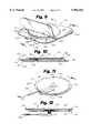
- FIG. 7is a top view of another embodiment of the electrode.
- FIG. 8is a side view of the electrode shown in FIG. 7;
- FIG. 9is a top view of another embodiment of electrode.
- FIG. 10is a side view of the electrode shown in FIG. 9;
- FIG. 11is a top view of another embodiment of the electrode.
- FIG. 12is a side view of the electrode shown in FIG. 11;
- FIG. 13is a top view of another embodiment of the electrode.
- FIG. 14is a side view of the electrode shown in FIG. 13;
- FIG. 15is a detailed view of a snap-type connection
- FIG. 16is a detailed view of a top member of the snap connection shown in FIG. 15;
- FIG. 17is a cross-sectional view of a resistive layer
- FIG. 18is a cross-sectional view of packaging material layers
- FIG. 19is a cross-sectional view of another embodiment having snap connectors and a conductive liner
- FIG. 20is a perspective view of another embodiment with a portion of the package broken away.
- FIG. 21is a section view of the embodiment of FIG. 20 taken along line 21 thereof.
- the present inventionprovides an electrode system for use in the medical arts, particularly in cardiac defibrillation.
- the systemincludes cooperating electrode embodiments, packaging embodiments and test instrumentation.
- the systemprovides convenient, secure and sterile storage means for electrodes which are easy to manufacture and use.
- the systemalso provides a means of periodically testing the operability of the stored electrodes without destroying the packaging or electrode, and without compromising the sterility of the materials.
- the teachings of this inventionare applicable to electrodes used for either or both transmitting or receiving, although they are particularly beneficial for use in electrodes used in cardiac defibrillation, which electrodes require transfer of particularly high currents and voltages and a high confidence that the packaged electrodes are in a state of readiness for use after long periods of storage.
- an embodiment of the packaged electrode system 10is shown to comprise an electrode 11 and a package or enclosure 12. Also shown in FIG. 2 is a test apparatus 13.
- the electrode 11is shown to comprise a non-conductive base or backing layer 14, a conductor or conductive layer 15, a lead 16, and a conductive contact layer 17.
- the base layer 14is preferably constructed of a thin, flexible polymeric substance such as a urethane foam, or a polyester or polyolefin laminate which provides structural base and insulative properties.
- the base layer 14is shown to have a surface area which is substantially coextensive with the surface of the contact layer 17. Alternatively the base layer 14 may be slightly larger than the contact layer 17. In such larger configurations, the base layer 14 may have a pressure sensitive adhesive disposed peripheral to the contact layer 17 on the patient contact side for increased adhesion to the patient's body.
- the conductive layer 15is shown to be disposed on the first or patient side of base layer 14.
- the conductive layer 15functions to transfer (disperse) current or voltage from the lead 16 (or to the lead 16 when the electrode 11 is employed in a sensing application) to the patient contact layer 17.
- the conductive layer 15is shown to have a surface area which is smaller than that of the base layer 14 or contact layer 17, it may alternatively have a dimension which is larger than that shown, or even one which is coextensive with the base layer 14 and contact layer 17.
- the conductive layer 15is preferably a homogeneous, solid, thinly deposited metallic substance, or a conductive ink material.
- the conductive layer 15may be formed of a flexible mesh material, a conductive adhesive or a deposited ink pattern.
- Flexible conductive ink compounds known in the arthave a conductive filler of gold, silver, aluminum or other conductive materials.
- the lead 16is preferably an insulated wire conductor which extends from a mating point with the conductive layer 15, through the base layer 14, and then has a freely movable end.
- the conductive contact layer 17is preferably a thin layer of semi-liquid gel material.
- the gelmaintains direct electrical contact with the skin of the patient to reduce variations in conductance. The gel permits such contact for long periods of time.
- the gelis a conductive, gelatinous compound which is also flexible for contoured adhesion to the body of a patient.
- the gelalso preferably has a pressure sensitive, moisture resistant adhesive property. Compounds having these characteristics have been developed by Minnesota Mining and Manufacturing, Medtronic, and Lec Tec (SynkaraTM), Corporations, all of Minnesota, U.S.A. Generally, these compounds have low electrical resistance.
- the contact layer 17is for direct contact with the patient's body to transfer current or voltage thereto or therefrom. Overall, although the electrode 11 and its constituent elements are shown to have circular configurations, they may alternatively be formed in various other shapes such as rectangular or square patches.
- the package structure 12is shown to have an envelope-like structure formed of a substantially continuous thin, homogeneous layer 18 of a polymeric, preferably substantially non-gas permeable, material.
- the package 87 embodimentmay have a pouch-like structure formed of a pair of thin, flat homogeneous layers 88 and 89 which are sealed or otherwise merged together at their peripheries or outer edges 90.
- a pair of spaced apart conductive connectors 91are formed unitary with layer 88 for electrical contact with contact layer 17.
- the package 12is shown to have a rectangular configuration various other configurations and shapes are also useable consistent with the invention.
- the package 12further comprises a pair of conductive connectors 19 and 20 which are separated a predetermined distance from one another for contact with separate areas of the contact layer 17 of the enclosed electrode 11.
- the connectors 19 and 20are conductive areas which are shown to have a unitary construction with the package layer 18.
- the connectors 19 and 20may alternatively be formed of thin layer strips of conductive material, or a printed conductive ink, disposed on the interior side of the package layer 18, extending from contact nodes on the interior of package layer 18 to peripheral contact areas on the exterior of the package 18.
- Yet another snap-type embodiment 79is shown in FIGS.
- the 15 and 16including a connective member 80 disposed on one side of the base layer 18, and a current dispersion member 81 disposed on the opposite side and being connected to the upper member 80 via an aperture in the base 18.
- the upper member 80is shown to have a base 82 and a mating notch 83 for coupling the lower member 81.
- the system 10 of the present inventionalso comprises a test apparatus 13.
- the test apparatus 13includes a current source 23, preferably a battery, test circuitry 24, preferably including measurement components and status indication components such as an analog meter, LCD digital display or light emitting diodes, and connectors 21 and 22 for coupling with the package 12 connectors 19 and 20.
- the test apparatus 13is connected to the package connectors 19 and 20.
- the test circuitry 24is then activated to form a closed current loop to determine whether continuity exists with respect to the enclosed electrode 11, thereby indicating whether the electrode 11 is still functional.
- a load 85a formed of for example a conductive and semi-conductive material layers 85 and 86may be added to the current loop as for example is shown in FIG. 17, for purposes of measuring the magnitude of current flow for more precise measurement of electrode 11 condition.
- a current loopis formed including the connector 19, the gel of the contact layer 17 (along a substantially horizontal plane), and the connector 20 which is located at a remote location on the contact layer 14 with respect to the connector 19.
- Currentconducts easily in fresh, semi-liquid gel of the contact layer 17.
- no current conducts, or current conductionis attenuated, in stale, dried gel. This is indicative of the need to dispose of the stored electrode without using it. And, this condition is determinable without the need to open the package 12 and thereby risk compromising the freshness or sterility of a viable electrode 11.
- FIGS. 3 and 4another embodiment of the packaged electrode system 30 is shown to comprise an electrode 31 and a package or enclosure 32.
- the electrode 31is shown to comprise a non-conductive base layer 33, and a conductive gel layer 36.
- a conductive snap-type connector 40having a connection member 35 disposed on one side and a current dispersion member 34 disposed on the second side is also shown.
- the package 32is shown to have at least one body layer 37 with a pair of contacts 38 and 39 disposed at predetermined locations to electrically connect with the gel layer 36 and connection member 35. In a test mode, a current loop is formed between the contact 39, gel layer 36, current dispersion member 34 and connection member 35 and connector 38.
- FIGS. 5 and 6another embodiment of the packaged electrode system 45 is shown to comprise an electrode 46 and an enclosure 47.
- the electrode 46is shown to comprise a non-conductive base layer 48, a conductive gel layer 55, and a pair of separate conductive layers 49 and 50, each of which are shown to have a lead 51 and 52 extending therefrom and terminating in a connective node 53 and 54.
- the lead pair 51 and 52(and layer pair 49 and 50) provide a redundant circuit path for increased reliability of use in emergency settings.
- the package 47is shown to have at least one body layer 56 with a pair of contacts 57 and 58 disposed at predetermined locations to electrically couple with connective nodes 53 and 54.
- a current loopis formed between a contacts 57 or 58, it's respective connective node 53 or 54 and lead 51 or 52, and its respective conductive layer 49 or 50.
- a properly functioning electrode 46current conducts through the gel 55 from one conductive layer 49 to the other 50, and then back to the test apparatus through the above-mentioned path.
- FIGS. 7 and 8another embodiment of the packaged electrode system 64 is shown to comprise an electrode 65 and a unitary package 66.
- the electrode 65is shown to comprise a non-conductive base layer 67, and a conductive gel layer 70.
- a snap-type connector with members 68 and 69is electrically coupled to the gel layer 70.
- the package 66is shown to have at least one body layer 71 which is coupled to the electrode base layer 67 at tear-away perforated lines 73.
- a connector 72is shown in FIG. 8 disposed for contact with the electrode gel layer 70. In a test mode, a current loop is formed between the connector 72, the gel layer 70, and the snap-type connector members 68 and 69.
- FIGS. 9 and 10another embodiment of the packaged electrode system 97 is shown to comprise an electrode 98 and a package 96.
- the electrode 98is shown to comprise a non-conductive base layer 101, a conductive gel layer 102, and a lead 104 having a conductor 105 and an insulator 106, which is shown to be embedded directly in the gel layer 102.
- the lead 104may be connected to a conductive current dispersion layer (not shown).
- a conductive test strip 103is also shown to be adhered to the surface of the gel 102 at a location remote from the lead 104 for test purposes. Test strip 103 is bonded to package layer 99 and is designed to release from the gel 102 upon removal of the package layer 99.
- the package 96is shown to have a pair of layers 99 and 100 which overlap to form an interior cavity 107 and are sealingly connected at their peripheries 108.
- a current loopis formed between the lead 104, the gel layer 102 and the test strip 103.
- the test strip 103 and the lead 104are shown extended through the package periphery 108 for contact with an external test apparatus.
- FIGS. 11 and 12another embodiment of the packaged electrode system 114 is shown to comprise an electrode 115 and an enclosure 113.
- the electrode 115is shown to comprise a non-conductive base layer 117, and a conductive adhesive gel layer 118 which is connected to a snap-type connection node 121 or the like, and an associated lead 120.
- the package 113is shown to comprise a single top layer of non-conductive material 116 which is laminated or adhesively mated to the periphery of the electrode base layer 117. In use, the gel layer 118 is releasable from the package layer 116.
- a test strip 119is disposed on the interior of the package 113, adhesively connected to the gel layer 118, and extending to the package exterior. In a test mode, a current loop is formed between the lead 120, node 121, gel layer 118 and the test strip 119.
- FIGS. 13 and 14another embodiment of the packaged electrode system 127 is shown to comprise a pair of electrodes 128 and 129 and a package 126.
- the electrodes 128 and 129are shown to comprise non-conductive base layers 130 and 133, and conductive gel layers 131 and 134. Leads 132 and 135 extend from the respective gel layers 131 and 134.
- the package 126is shown to have a pair of overlapping layers 142 and 143 which are sealed at their peripheries 141 to form an enclosure 140 housing the electrodes 128 and 129.
- the electrodes 128 and 129are oriented with their respective gel layers 131 and 134 mating with a resistive layer 137 (and an optional separator layer 136) formed of a conductive/resistive material as known in the art.
- a conductive lead 139 or stripextends from the resistive layer through the package periphery 141, as do the electrode leads 132 and 135.
- a current loopis formed between, for example, a lead 132, the gel layer 131, the resistive layer 137, and the remaining gel layer 134 and lead 135.
- the circuitcan be altered to include the lead 139.
- FIG. 19depicts a further embodiment of the present invention.
- a packaged electrode systemis shown generally at 180.
- the packaged electrode system 180includes a first electrode 182, a second electrode 184, and an enclosing package 196.
- the package 196is formed of package portion 197a, 197b, bonded at the peripheries thereof to define an enclosure 189.
- a conductive polymeric liner 198is disposed between the electrodes 182, 184.
- Each of the electrodes 182, 184has a nonconductive base 186, 188, respectively.
- a respective conductive gel layer 190, 192is operably coupled to the nonconductive base 186, 188.
- Snap connectors 194a, 194bare operably coupled to the nonconductive bases 186, 18 and communicatively coupled to the conductive gel layers 190, 192. As previously described in reference to FIGS. 3 and 4, the snap connectors 194a, 194b each have a connection member 35 disposed on one side of the respective nonconductive bases 186, 18 and a current dispersion member 34 that is communicatively coupled to the conducting gel layers 190, 192.
- Contacts 195a, 195bare preferably formed unitary with the respective package portion 197a, 197b and are disposed proximate the snap connectors 194a, 194b.
- the contacts 195a, 195bare normally positioned spaced apart from the snap connectors 194a, 194b. The spacing electrically isolates the contacts 195a, 195b and snap connectors 194a, 194b. Depressing the contacts 195a, 195b causes the contacts 195a, 195b to come into physical and electrical contact with the snap connectors 194a, 194b.
- the packaged electrode system 180may additionally have an associated lead coupled to each of the snap connectors 194a, 194b.
- a leadis similar to the associated lead 120, previously described in reference to FIGS. 11 and 12, coupled to the connection member 35 of each of the snap connectors 194a, 194b.
- the use of such associated leads 120negates the need for contacts 195a, 195b.
- the associate leadpreferably carries through an aperture defined in the package 196, for connection external to the package 196, as desired.
- the electrodes 182, 184are disposed within the enclosure 189 formed by the package 196 with the respective conductive gel layers 190, 192 in a facing relationship.
- the conductive liner 198is interposed between the conductive gel layers 190 and 192.
- the conductive liner 198physically separates the conductive gel layers 190, 192 and communicatively couples conductive gel layers 190, 192.
- the conductive gel layers 190 192are readily releasable from the conductive liner 198.
- the conductive polymeric liner 198is inherently conductive by the nature of its structure.
- Such inherently conductive structureincludes alternating double or triple bonded polymers.
- the conductive polymeric liner 198may not be inherently conductive but may be doped or filled with conductive particles such as graphite, carbon black, and metal powder in order to provide conductivity.
- Examples of doped or filled conductive polymers suitable to form the conductive polymeric liner 198include:
- PEdoped polyethylene
- polyfluorinated hydrocarbonsare of particular interest for use in forming the conductive polymeric liner 198 because of their exhibited low adhesion properties.
- polyfluorinated ethyleneis preferred because this polymer is extrudable, making it easier to form the conductive polymeric liner 198.
- FIGS. 20 and 21A further embodiment of the packaged electrode system of the present invention is depicted in FIGS. 20 and 21.
- a packaged electrode systemis shown generally at 200.
- the packaged electrode system 200includes a first electrode 202, a second electrode 204, and an enclosing package 220.
- the electrodes 202, 204are releasably disposed in an enclosure 221 defined by the package 220.
- a conductive polymeric liner 226is disposed between the electrodes 202, 204.
- Each of the electrodes 202, 204has a nonconductive base 206, 208, respectively.
- a respective conductive gel layer 210, 212is operably coupled to the nonconductive base 206, 208.
- Leads 214, 216are communicatively coupled to the conductive gel layers 210, 212.
- the leads 214, 216pass through an aperture 217 defined in the periphery of the package 220 for connection to conductors external to the package 220 as desired.
- the package 220has a top package portion 222 and a bottom package portion 224.
- the package portions 222, 224are sealed at their peripheries to form the enclosure 221, housing the electrodes 202, 204.
- a conductive polymeric liner 226is disposed between the electrodes 202, 204.
- the electrodes 202, 204are disposed within the enclosure formed by the package 220 with the conductive gel layers 210, 212 in a facing relationship.
- the liner 226is interposed between the conductive gel layers 210 and 212.
- the liner 226both physically separates the conductive gel layers 210, 212 and communicatively couples conductive gel layers 210, 212.
- Lead 228is communicatively coupled to the conductive polymeric liner 226.
- the lead 228passes through the aperture 217 defined in the periphery of the package 220 for connection to conductors external to the package 220 as desired.
- the conductive polymeric liner 226is inherently conductive by the nature of its structure and is substantially identical to the conductive polymeric liner 198 described in conjunction with FIG. 19 above.
Landscapes
- Health & Medical Sciences (AREA)
- Engineering & Computer Science (AREA)
- Biomedical Technology (AREA)
- Nuclear Medicine, Radiotherapy & Molecular Imaging (AREA)
- Radiology & Medical Imaging (AREA)
- Life Sciences & Earth Sciences (AREA)
- Animal Behavior & Ethology (AREA)
- General Health & Medical Sciences (AREA)
- Public Health (AREA)
- Veterinary Medicine (AREA)
- Electrotherapy Devices (AREA)
Abstract
Description
Claims (32)
Priority Applications (1)
| Application Number | Priority Date | Filing Date | Title |
|---|---|---|---|
| US09/033,294US5984102A (en) | 1992-09-24 | 1998-03-02 | Medical electrode packaging technology |
Applications Claiming Priority (4)
| Application Number | Priority Date | Filing Date | Title |
|---|---|---|---|
| US07/950,823US5402884A (en) | 1992-09-24 | 1992-09-24 | Medical electrode packaging technology |
| US08/411,102US5579919A (en) | 1992-09-24 | 1995-03-27 | Medical electrode packaging technology |
| US08/712,224US5850920A (en) | 1992-09-24 | 1996-09-11 | Medical electrode packaging technology |
| US09/033,294US5984102A (en) | 1992-09-24 | 1998-03-02 | Medical electrode packaging technology |
Related Parent Applications (1)
| Application Number | Title | Priority Date | Filing Date |
|---|---|---|---|
| US08/712,224Continuation-In-PartUS5850920A (en) | 1992-09-24 | 1996-09-11 | Medical electrode packaging technology |
Publications (1)
| Publication Number | Publication Date |
|---|---|
| US5984102Atrue US5984102A (en) | 1999-11-16 |
Family
ID=27410888
Family Applications (1)
| Application Number | Title | Priority Date | Filing Date |
|---|---|---|---|
| US09/033,294Expired - LifetimeUS5984102A (en) | 1992-09-24 | 1998-03-02 | Medical electrode packaging technology |
Country Status (1)
| Country | Link |
|---|---|
| US (1) | US5984102A (en) |
Cited By (106)
| Publication number | Priority date | Publication date | Assignee | Title |
|---|---|---|---|---|
| US6142305A (en)* | 1999-09-16 | 2000-11-07 | Aaron Medical Industries, Inc. | Protective tray for loop electrode |
| US6223898B1 (en)* | 1995-08-18 | 2001-05-01 | Tetra Laval Holdings & Finance S.A. | Quality control packaging container |
| US6272385B1 (en)* | 1998-09-01 | 2001-08-07 | Agilent Technologies, Inc. | Independently deployable sealed defibrillator electrode pad and method of use |
| US6292697B1 (en) | 2000-02-15 | 2001-09-18 | Medtronic, Inc. | Testing sterile packaged components of an implantable medical device prior to chronic implantation |
| US20020128685A1 (en)* | 1998-07-31 | 2002-09-12 | Harbinger Medical, Inc. | Apparatus and method for detecting lead adequacy and quality |
| US20030017743A1 (en)* | 2001-02-28 | 2003-01-23 | Agilent Technologies | Electrode-pad package that is removable from an electrode-pad lead and method for opening the package |
| WO2003022146A1 (en)* | 2001-09-07 | 2003-03-20 | Brown, Stephen, Colin | Contact electrode |
| US6564079B1 (en) | 2000-07-27 | 2003-05-13 | Ckm Diagnostics, Inc. | Electrode array and skin attachment system for noninvasive nerve location and imaging device |
| US6603318B2 (en)* | 2001-02-22 | 2003-08-05 | Koninklijke Philips Electronics N.V. | Method of determining when electrode pads are unsuitable for use by detecting relative humidity |
| US6613035B1 (en)* | 1996-04-25 | 2003-09-02 | C. R. Bard, Inc. | Autotransfusion system and method |
| US20030171797A1 (en)* | 2002-03-08 | 2003-09-11 | Nova Richard C. | Therapy and monitoring electrodes with patient accommodating features |
| US6711427B1 (en) | 2002-02-13 | 2004-03-23 | Milwaukee Electronics Corporation | Skin abrading medical electrode mounting and packaging system |
| US6743223B1 (en)* | 1999-04-29 | 2004-06-01 | Leonhard Lang Kg | Neutral electrode |
| WO2004058345A1 (en)* | 2002-12-20 | 2004-07-15 | Metrax Gmbh | Electrode pack |
| US6800278B1 (en) | 1996-10-28 | 2004-10-05 | Ballard Medical Products, Inc. | Inherently antimicrobial quaternary amine hydrogel wound dressings |
| US20050075695A1 (en)* | 2003-10-02 | 2005-04-07 | Medtronic, Inc. | Storable implantable medical device assembly allowing in package charging |
| WO2003084600A3 (en)* | 2002-04-08 | 2005-10-20 | Koninkl Philips Electronics Nv | Sterile disposable internal defibrillation paddles |
| US20050277991A1 (en)* | 2004-06-10 | 2005-12-15 | Covey Kevin K | Assessing medical electrode condition |
| US20050283219A1 (en)* | 2004-06-16 | 2005-12-22 | O'connor Rose M | Packaging for medical pads and electrodes |
| WO2006046160A1 (en)* | 2004-10-29 | 2006-05-04 | Koninklijke Philips Electronics, N.V. | Electrode and enclosure for cardiac monitoring and treatment |
| WO2006033021A3 (en)* | 2004-09-22 | 2006-05-04 | Heartsine Technologies Ltd | Sealed medical electrode package |
| USD522374S1 (en)* | 2004-04-30 | 2006-06-06 | Medtronic Emergency Response Systems, Inc. | Package for one or more external defibrillator electrodes |
| US20070203558A1 (en)* | 2004-03-23 | 2007-08-30 | Koninklijke Phillips Electronics N.V. | Self-Storing Medical Electrodes |
| US20070255380A1 (en)* | 2006-04-27 | 2007-11-01 | Peter Meyer | Electrode pad packaging systems and methods |
| US20080009911A1 (en)* | 2006-07-05 | 2008-01-10 | Dupelle Michael R | Condition sensor for medical device package |
| US20080009930A1 (en)* | 2006-07-05 | 2008-01-10 | Dupelle Michael R | Breakaway electrical connections for defibrillation electrode package |
| US20080103557A1 (en)* | 2006-10-31 | 2008-05-01 | Medtronic, Inc. | Extended shelf life storable implantable medical device assembly, shipping container and method |
| WO2008089186A1 (en)* | 2007-01-15 | 2008-07-24 | Oliver Products Company | Cover with circuit |
| USRE40471E1 (en) | 1998-10-29 | 2008-08-26 | Cardiac Science, Inc. | AED with force sensor |
| WO2009036348A1 (en)* | 2007-09-14 | 2009-03-19 | Corventis, Inc. | Medical device automatic start-up upon contact to patient tissue |
| EP2105162A2 (en) | 2008-03-26 | 2009-09-30 | Cardiac Science Corporation | Method and apparatus for defrosting a defibrillation electrode |
| WO2011036583A1 (en)* | 2009-09-28 | 2011-03-31 | Koninklijke Philips Electronics, N.V. | Defibrillator with pre-connected electrode pads with reduced susceptibility to false asystole indications |
| USRE43050E1 (en) | 2001-09-14 | 2011-12-27 | Koninklijke Philips Electronics N.V. | Medical electrode and release liner configurations facilitating packaged electrode characterization |
| US8116841B2 (en) | 2007-09-14 | 2012-02-14 | Corventis, Inc. | Adherent device with multiple physiological sensors |
| EP2150313A4 (en)* | 2007-04-24 | 2012-06-27 | St Jude Medical | SYSTEM, APPARATUS AND CONTAINER FOR STORING AN IMPLANTABLE MEDICAL DEVICE, AND METHOD FOR CONDITIONING SUCH A DEVICE |
| US20120183942A1 (en)* | 2011-01-17 | 2012-07-19 | Pastrick John J | Manikin Sensing Pads and Liners in an AED Training System |
| US8249686B2 (en) | 2007-09-14 | 2012-08-21 | Corventis, Inc. | Adherent device for sleep disordered breathing |
| USD675739S1 (en) | 2011-12-07 | 2013-02-05 | Cardiac Science Corporation | Automated external defibrillator electrode pad |
| US8374688B2 (en) | 2007-09-14 | 2013-02-12 | Corventis, Inc. | System and methods for wireless body fluid monitoring |
| US8412317B2 (en) | 2008-04-18 | 2013-04-02 | Corventis, Inc. | Method and apparatus to measure bioelectric impedance of patient tissue |
| US8460189B2 (en) | 2007-09-14 | 2013-06-11 | Corventis, Inc. | Adherent cardiac monitor with advanced sensing capabilities |
| US8613709B2 (en) | 2010-10-08 | 2013-12-24 | Cardiac Science Corporation | Ambulatory electrocardiographic monitor for providing ease of use in women |
| US8613708B2 (en) | 2010-10-08 | 2013-12-24 | Cardiac Science Corporation | Ambulatory electrocardiographic monitor with jumpered sensing electrode |
| US8626277B2 (en) | 2010-10-08 | 2014-01-07 | Cardiac Science Corporation | Computer-implemented electrocardiographic data processor with time stamp correlation |
| US8684925B2 (en) | 2007-09-14 | 2014-04-01 | Corventis, Inc. | Injectable device for physiological monitoring |
| US8718752B2 (en) | 2008-03-12 | 2014-05-06 | Corventis, Inc. | Heart failure decompensation prediction based on cardiac rhythm |
| USD706432S1 (en)* | 2011-10-05 | 2014-06-03 | Bioelectronics Corp. | Pulsed electromagnetic field device with peel-off style mounting strip |
| US8790259B2 (en) | 2009-10-22 | 2014-07-29 | Corventis, Inc. | Method and apparatus for remote detection and monitoring of functional chronotropic incompetence |
| US8823490B2 (en) | 2008-12-15 | 2014-09-02 | Corventis, Inc. | Patient monitoring systems and methods |
| USD717955S1 (en) | 2013-11-07 | 2014-11-18 | Bardy Diagnostics, Inc. | Electrocardiography monitor |
| USD720213S1 (en)* | 2014-04-18 | 2014-12-30 | Line One Laboratories Inc. (USA) | Heart shaped condom package |
| US8965498B2 (en) | 2010-04-05 | 2015-02-24 | Corventis, Inc. | Method and apparatus for personalized physiologic parameters |
| US9037477B2 (en) | 2010-10-08 | 2015-05-19 | Cardiac Science Corporation | Computer-implemented system and method for evaluating ambulatory electrocardiographic monitoring of cardiac rhythm disorders |
| US9091718B2 (en) | 2011-09-15 | 2015-07-28 | Zoll Medical Corporation | Testing electrical connections between cardiac resuscitation devices and external electrodes |
| USD744659S1 (en) | 2013-11-07 | 2015-12-01 | Bardy Diagnostics, Inc. | Extended wear electrode patch |
| US9345414B1 (en) | 2013-09-25 | 2016-05-24 | Bardy Diagnostics, Inc. | Method for providing dynamic gain over electrocardiographic data with the aid of a digital computer |
| US9364155B2 (en) | 2013-09-25 | 2016-06-14 | Bardy Diagnostics, Inc. | Self-contained personal air flow sensing monitor |
| US9408551B2 (en) | 2013-11-14 | 2016-08-09 | Bardy Diagnostics, Inc. | System and method for facilitating diagnosis of cardiac rhythm disorders with the aid of a digital computer |
| US9411936B2 (en) | 2007-09-14 | 2016-08-09 | Medtronic Monitoring, Inc. | Dynamic pairing of patients to data collection gateways |
| US9408545B2 (en) | 2013-09-25 | 2016-08-09 | Bardy Diagnostics, Inc. | Method for efficiently encoding and compressing ECG data optimized for use in an ambulatory ECG monitor |
| US9433367B2 (en) | 2013-09-25 | 2016-09-06 | Bardy Diagnostics, Inc. | Remote interfacing of extended wear electrocardiography and physiological sensor monitor |
| US9433380B1 (en) | 2013-09-25 | 2016-09-06 | Bardy Diagnostics, Inc. | Extended wear electrocardiography patch |
| USD766447S1 (en) | 2015-09-10 | 2016-09-13 | Bardy Diagnostics, Inc. | Extended wear electrode patch |
| US9451897B2 (en) | 2009-12-14 | 2016-09-27 | Medtronic Monitoring, Inc. | Body adherent patch with electronics for physiologic monitoring |
| US9504423B1 (en) | 2015-10-05 | 2016-11-29 | Bardy Diagnostics, Inc. | Method for addressing medical conditions through a wearable health monitor with the aid of a digital computer |
| US9545204B2 (en) | 2013-09-25 | 2017-01-17 | Bardy Diagnostics, Inc. | Extended wear electrocardiography patch |
| US9619660B1 (en) | 2013-09-25 | 2017-04-11 | Bardy Diagnostics, Inc. | Computer-implemented system for secure physiological data collection and processing |
| US9615763B2 (en) | 2013-09-25 | 2017-04-11 | Bardy Diagnostics, Inc. | Ambulatory electrocardiography monitor recorder optimized for capturing low amplitude cardiac action potential propagation |
| US9655538B2 (en) | 2013-09-25 | 2017-05-23 | Bardy Diagnostics, Inc. | Self-authenticating electrocardiography monitoring circuit |
| US9655537B2 (en) | 2013-09-25 | 2017-05-23 | Bardy Diagnostics, Inc. | Wearable electrocardiography and physiology monitoring ensemble |
| US9700227B2 (en) | 2013-09-25 | 2017-07-11 | Bardy Diagnostics, Inc. | Ambulatory electrocardiography monitoring patch optimized for capturing low amplitude cardiac action potential propagation |
| USD793566S1 (en) | 2015-09-10 | 2017-08-01 | Bardy Diagnostics, Inc. | Extended wear electrode patch |
| US9717432B2 (en) | 2013-09-25 | 2017-08-01 | Bardy Diagnostics, Inc. | Extended wear electrocardiography patch using interlaced wire electrodes |
| US9717433B2 (en) | 2013-09-25 | 2017-08-01 | Bardy Diagnostics, Inc. | Ambulatory electrocardiography monitoring patch optimized for capturing low amplitude cardiac action potential propagation |
| US9737224B2 (en) | 2013-09-25 | 2017-08-22 | Bardy Diagnostics, Inc. | Event alerting through actigraphy embedded within electrocardiographic data |
| US9775536B2 (en) | 2013-09-25 | 2017-10-03 | Bardy Diagnostics, Inc. | Method for constructing a stress-pliant physiological electrode assembly |
| USD801528S1 (en) | 2013-11-07 | 2017-10-31 | Bardy Diagnostics, Inc. | Electrocardiography monitor |
| USD831833S1 (en) | 2013-11-07 | 2018-10-23 | Bardy Diagnostics, Inc. | Extended wear electrode patch |
| US10165946B2 (en) | 2013-09-25 | 2019-01-01 | Bardy Diagnostics, Inc. | Computer-implemented system and method for providing a personal mobile device-triggered medical intervention |
| US10251576B2 (en) | 2013-09-25 | 2019-04-09 | Bardy Diagnostics, Inc. | System and method for ECG data classification for use in facilitating diagnosis of cardiac rhythm disorders with the aid of a digital computer |
| US10433748B2 (en) | 2013-09-25 | 2019-10-08 | Bardy Diagnostics, Inc. | Extended wear electrocardiography and physiological sensor monitor |
| US10433751B2 (en) | 2013-09-25 | 2019-10-08 | Bardy Diagnostics, Inc. | System and method for facilitating a cardiac rhythm disorder diagnosis based on subcutaneous cardiac monitoring data |
| US10463269B2 (en) | 2013-09-25 | 2019-11-05 | Bardy Diagnostics, Inc. | System and method for machine-learning-based atrial fibrillation detection |
| US10624551B2 (en) | 2013-09-25 | 2020-04-21 | Bardy Diagnostics, Inc. | Insertable cardiac monitor for use in performing long term electrocardiographic monitoring |
| US10667711B1 (en) | 2013-09-25 | 2020-06-02 | Bardy Diagnostics, Inc. | Contact-activated extended wear electrocardiography and physiological sensor monitor recorder |
| USD892340S1 (en) | 2013-11-07 | 2020-08-04 | Bardy Diagnostics, Inc. | Extended wear electrode patch |
| US10736531B2 (en) | 2013-09-25 | 2020-08-11 | Bardy Diagnostics, Inc. | Subcutaneous insertable cardiac monitor optimized for long term, low amplitude electrocardiographic data collection |
| US10736529B2 (en) | 2013-09-25 | 2020-08-11 | Bardy Diagnostics, Inc. | Subcutaneous insertable electrocardiography monitor |
| US10799137B2 (en) | 2013-09-25 | 2020-10-13 | Bardy Diagnostics, Inc. | System and method for facilitating a cardiac rhythm disorder diagnosis with the aid of a digital computer |
| US10806360B2 (en) | 2013-09-25 | 2020-10-20 | Bardy Diagnostics, Inc. | Extended wear ambulatory electrocardiography and physiological sensor monitor |
| US10820801B2 (en) | 2013-09-25 | 2020-11-03 | Bardy Diagnostics, Inc. | Electrocardiography monitor configured for self-optimizing ECG data compression |
| US10888239B2 (en) | 2013-09-25 | 2021-01-12 | Bardy Diagnostics, Inc. | Remote interfacing electrocardiography patch |
| USD926323S1 (en) | 2020-03-30 | 2021-07-27 | Zoll Medical Corporation | Automated external defibrillator electrode pad |
| US11096579B2 (en) | 2019-07-03 | 2021-08-24 | Bardy Diagnostics, Inc. | System and method for remote ECG data streaming in real-time |
| US11116451B2 (en) | 2019-07-03 | 2021-09-14 | Bardy Diagnostics, Inc. | Subcutaneous P-wave centric insertable cardiac monitor with energy harvesting capabilities |
| US11134684B2 (en) | 2005-08-24 | 2021-10-05 | Purdue Research Foundation | Method of using hydrophilized bactericidal polymers |
| US11213237B2 (en) | 2013-09-25 | 2022-01-04 | Bardy Diagnostics, Inc. | System and method for secure cloud-based physiological data processing and delivery |
| US11324441B2 (en) | 2013-09-25 | 2022-05-10 | Bardy Diagnostics, Inc. | Electrocardiography and respiratory monitor |
| US11421084B2 (en) | 2017-05-27 | 2022-08-23 | Poly Group LLC | Dispersible antimicrobial complex and coatings therefrom |
| US11680116B2 (en) | 2017-06-16 | 2023-06-20 | Poly Group LLC | Polymeric antimicrobial surfactant |
| US11678830B2 (en) | 2017-12-05 | 2023-06-20 | Bardy Diagnostics, Inc. | Noise-separating cardiac monitor |
| US11696681B2 (en) | 2019-07-03 | 2023-07-11 | Bardy Diagnostics Inc. | Configurable hardware platform for physiological monitoring of a living body |
| US11723575B2 (en) | 2013-09-25 | 2023-08-15 | Bardy Diagnostics, Inc. | Electrocardiography patch |
| US12012270B2 (en)* | 2018-12-20 | 2024-06-18 | Conmed Corporation | Medical electrode tear strip |
| USD1084345S1 (en) | 2022-07-28 | 2025-07-15 | Zoll Medical Corporation | Chest compression sensor |
| USD1084346S1 (en) | 2022-07-28 | 2025-07-15 | Zoll Medical Corporation | Chest compression sensor |
Citations (26)
| Publication number | Priority date | Publication date | Assignee | Title |
|---|---|---|---|---|
| US3086652A (en)* | 1961-07-26 | 1963-04-23 | Western Electric Co | Handling cards for components |
| US3198329A (en)* | 1963-07-22 | 1965-08-03 | Acrovox Corp | Packaging of tubular articles |
| US3265945A (en)* | 1964-10-27 | 1966-08-09 | Sprague Electric Co | Packaged capacitor and method of making the same |
| US3585275A (en)* | 1970-02-19 | 1971-06-15 | George W Gillemot | Kit and method for encapsulating conductor splice connections |
| US3602216A (en)* | 1969-09-16 | 1971-08-31 | United Aircraft Corp | Paste dispensing body electrode |
| US3685645A (en)* | 1970-08-17 | 1972-08-22 | Physio Control Corp | Defibrillation electrode pad and package therefor |
| US3701346A (en)* | 1971-01-04 | 1972-10-31 | Bionetics Inc | Medical electrode |
| US3798329A (en)* | 1970-04-22 | 1974-03-19 | Ciba Geigy Corp | 1-aminoalkyl-dibenzosemibullvalenes as antidepressants |
| US3805769A (en)* | 1971-08-27 | 1974-04-23 | R Sessions | Disposable electrode |
| US3830229A (en)* | 1972-08-09 | 1974-08-20 | J Johnson | Disposable body electrodes |
| US3834373A (en)* | 1972-02-24 | 1974-09-10 | T Sato | Silver, silver chloride electrodes |
| US3868946A (en)* | 1973-07-13 | 1975-03-04 | James S Hurley | Medical electrode |
| US3934373A (en)* | 1974-08-16 | 1976-01-27 | Wheelabrator-Frye, Inc. | Portable surface treating apparatus |
| US3961623A (en)* | 1975-01-17 | 1976-06-08 | Medical Research Laboratories, Inc. | Method of using a disposable electrode pad |
| US4029086A (en)* | 1975-08-11 | 1977-06-14 | Consolidated Medical Equipment, Inc. | Electrode arrangement |
| US4034854A (en)* | 1976-07-16 | 1977-07-12 | M I Systems, Inc. | Electrode package |
| US4040412A (en)* | 1974-08-09 | 1977-08-09 | Sato Takuya R | Bioelectrodes |
| US4092985A (en)* | 1974-11-25 | 1978-06-06 | John George Kaufman | Body electrode for electro-medical use |
| FR2483215A3 (en)* | 1980-06-02 | 1981-12-04 | Medtronic Inc | TEMPORARY PACKAGING FOR AN ELECTRICAL COMPONENT |
| US4423732A (en)* | 1980-09-26 | 1984-01-03 | Cordis Corporation | Sterile connector system for packaged pacer |
| US4439810A (en)* | 1981-09-10 | 1984-03-27 | Marcon Electronics Co., Ltd. | Electric capacitor with enclosure structure consisting of plastic laminated film |
| US4482313A (en)* | 1977-07-27 | 1984-11-13 | Stelrad Group Limited | Gasburner system |
| US4487313A (en)* | 1981-02-20 | 1984-12-11 | William C. Heller, Jr. | Enclosed moist pad assembly with removable cover |
| US4779630A (en)* | 1987-09-18 | 1988-10-25 | Katecho, Inc. | Defibrillator pad assembly and method for using same |
| US5402884A (en)* | 1992-09-24 | 1995-04-04 | Surviva Link Corporation | Medical electrode packaging technology |
| US5462157A (en)* | 1993-10-28 | 1995-10-31 | Zmd Corporation | Electrode package |
- 1998
- 1998-03-02USUS09/033,294patent/US5984102A/ennot_activeExpired - Lifetime
Patent Citations (28)
| Publication number | Priority date | Publication date | Assignee | Title |
|---|---|---|---|---|
| US3086652A (en)* | 1961-07-26 | 1963-04-23 | Western Electric Co | Handling cards for components |
| US3198329A (en)* | 1963-07-22 | 1965-08-03 | Acrovox Corp | Packaging of tubular articles |
| US3265945A (en)* | 1964-10-27 | 1966-08-09 | Sprague Electric Co | Packaged capacitor and method of making the same |
| US3602216A (en)* | 1969-09-16 | 1971-08-31 | United Aircraft Corp | Paste dispensing body electrode |
| US3585275A (en)* | 1970-02-19 | 1971-06-15 | George W Gillemot | Kit and method for encapsulating conductor splice connections |
| US3798329A (en)* | 1970-04-22 | 1974-03-19 | Ciba Geigy Corp | 1-aminoalkyl-dibenzosemibullvalenes as antidepressants |
| US3685645A (en)* | 1970-08-17 | 1972-08-22 | Physio Control Corp | Defibrillation electrode pad and package therefor |
| US3701346A (en)* | 1971-01-04 | 1972-10-31 | Bionetics Inc | Medical electrode |
| US3805769A (en)* | 1971-08-27 | 1974-04-23 | R Sessions | Disposable electrode |
| US3834373A (en)* | 1972-02-24 | 1974-09-10 | T Sato | Silver, silver chloride electrodes |
| US3830229A (en)* | 1972-08-09 | 1974-08-20 | J Johnson | Disposable body electrodes |
| US3868946A (en)* | 1973-07-13 | 1975-03-04 | James S Hurley | Medical electrode |
| US4040412A (en)* | 1974-08-09 | 1977-08-09 | Sato Takuya R | Bioelectrodes |
| US3934373A (en)* | 1974-08-16 | 1976-01-27 | Wheelabrator-Frye, Inc. | Portable surface treating apparatus |
| US4092985A (en)* | 1974-11-25 | 1978-06-06 | John George Kaufman | Body electrode for electro-medical use |
| US3961623A (en)* | 1975-01-17 | 1976-06-08 | Medical Research Laboratories, Inc. | Method of using a disposable electrode pad |
| US4029086A (en)* | 1975-08-11 | 1977-06-14 | Consolidated Medical Equipment, Inc. | Electrode arrangement |
| US4034854A (en)* | 1976-07-16 | 1977-07-12 | M I Systems, Inc. | Electrode package |
| US4482313A (en)* | 1977-07-27 | 1984-11-13 | Stelrad Group Limited | Gasburner system |
| FR2483215A3 (en)* | 1980-06-02 | 1981-12-04 | Medtronic Inc | TEMPORARY PACKAGING FOR AN ELECTRICAL COMPONENT |
| US4423732A (en)* | 1980-09-26 | 1984-01-03 | Cordis Corporation | Sterile connector system for packaged pacer |
| US4487313A (en)* | 1981-02-20 | 1984-12-11 | William C. Heller, Jr. | Enclosed moist pad assembly with removable cover |
| US4439810A (en)* | 1981-09-10 | 1984-03-27 | Marcon Electronics Co., Ltd. | Electric capacitor with enclosure structure consisting of plastic laminated film |
| US4779630A (en)* | 1987-09-18 | 1988-10-25 | Katecho, Inc. | Defibrillator pad assembly and method for using same |
| US5402884A (en)* | 1992-09-24 | 1995-04-04 | Surviva Link Corporation | Medical electrode packaging technology |
| US5579919A (en)* | 1992-09-24 | 1996-12-03 | Survivalink Corporation | Medical electrode packaging technology |
| US5850920A (en)* | 1992-09-24 | 1998-12-22 | Survivalink Corporation | Medical electrode packaging technology |
| US5462157A (en)* | 1993-10-28 | 1995-10-31 | Zmd Corporation | Electrode package |
Cited By (257)
| Publication number | Priority date | Publication date | Assignee | Title |
|---|---|---|---|---|
| US6223898B1 (en)* | 1995-08-18 | 2001-05-01 | Tetra Laval Holdings & Finance S.A. | Quality control packaging container |
| US6613035B1 (en)* | 1996-04-25 | 2003-09-02 | C. R. Bard, Inc. | Autotransfusion system and method |
| US6800278B1 (en) | 1996-10-28 | 2004-10-05 | Ballard Medical Products, Inc. | Inherently antimicrobial quaternary amine hydrogel wound dressings |
| US20020128685A1 (en)* | 1998-07-31 | 2002-09-12 | Harbinger Medical, Inc. | Apparatus and method for detecting lead adequacy and quality |
| US20070093871A1 (en)* | 1998-07-31 | 2007-04-26 | Harbinger Medical, Inc. | Apparatus and method for detecting lead adequacy and quality |
| US7171265B2 (en)* | 1998-07-31 | 2007-01-30 | Harbinger Medical, Inc. | Apparatus and method for detecting lead adequacy and quality |
| US7610091B2 (en)* | 1998-07-31 | 2009-10-27 | Harbinger Medical, Inc. | Apparatus and method for detecting lead adequacy and quality |
| US6272385B1 (en)* | 1998-09-01 | 2001-08-07 | Agilent Technologies, Inc. | Independently deployable sealed defibrillator electrode pad and method of use |
| USRE40471E1 (en) | 1998-10-29 | 2008-08-26 | Cardiac Science, Inc. | AED with force sensor |
| US6743223B1 (en)* | 1999-04-29 | 2004-06-01 | Leonhard Lang Kg | Neutral electrode |
| US6142305A (en)* | 1999-09-16 | 2000-11-07 | Aaron Medical Industries, Inc. | Protective tray for loop electrode |
| US6292697B1 (en) | 2000-02-15 | 2001-09-18 | Medtronic, Inc. | Testing sterile packaged components of an implantable medical device prior to chronic implantation |
| US6609018B2 (en) | 2000-07-27 | 2003-08-19 | Ckm Diagnostics, Inc. | Electrode array and sensor attachment system for noninvasive nerve location and imaging device |
| US6564079B1 (en) | 2000-07-27 | 2003-05-13 | Ckm Diagnostics, Inc. | Electrode array and skin attachment system for noninvasive nerve location and imaging device |
| US6603318B2 (en)* | 2001-02-22 | 2003-08-05 | Koninklijke Philips Electronics N.V. | Method of determining when electrode pads are unsuitable for use by detecting relative humidity |
| EP1402276A4 (en)* | 2001-02-22 | 2009-05-20 | Philips Electronics Na | Method of determining when electrode pads are unsuitable for use by detecting relative humidity |
| US20030017743A1 (en)* | 2001-02-28 | 2003-01-23 | Agilent Technologies | Electrode-pad package that is removable from an electrode-pad lead and method for opening the package |
| US6935889B2 (en)* | 2001-02-28 | 2005-08-30 | Koninklijke Philips Electronics N.V. | Electrode-pad package that is removable from an electrode-pad lead and method for opening the package |
| GB2418365B (en)* | 2001-09-07 | 2006-06-14 | Desmond Bryan Mills | Contact electrode |
| GB2418365A (en)* | 2001-09-07 | 2006-03-29 | Desmond Bryan Mills | Defibrillation contact electrode with self test features |
| US20040199237A1 (en)* | 2001-09-07 | 2004-10-07 | Mills Desmond Bryan | Contact electrode |
| US7729784B2 (en) | 2001-09-07 | 2010-06-01 | The Dezac Group Limited | Contact electrode |
| GB2380677B (en)* | 2001-09-07 | 2006-02-01 | Desmond Bryan Mills | Contact electrode |
| WO2003022146A1 (en)* | 2001-09-07 | 2003-03-20 | Brown, Stephen, Colin | Contact electrode |
| USRE43050E1 (en) | 2001-09-14 | 2011-12-27 | Koninklijke Philips Electronics N.V. | Medical electrode and release liner configurations facilitating packaged electrode characterization |
| US6711427B1 (en) | 2002-02-13 | 2004-03-23 | Milwaukee Electronics Corporation | Skin abrading medical electrode mounting and packaging system |
| US6965799B2 (en)* | 2002-03-08 | 2005-11-15 | Medtronic Physio-Control Manufacturing Corp. | Therapy and monitoring electrodes with patient accommodating features |
| US20030171797A1 (en)* | 2002-03-08 | 2003-09-11 | Nova Richard C. | Therapy and monitoring electrodes with patient accommodating features |
| WO2003084600A3 (en)* | 2002-04-08 | 2005-10-20 | Koninkl Philips Electronics Nv | Sterile disposable internal defibrillation paddles |
| US20050244709A1 (en)* | 2002-12-20 | 2005-11-03 | Jurgen Bucher | Electrode pack |
| WO2004058345A1 (en)* | 2002-12-20 | 2004-07-15 | Metrax Gmbh | Electrode pack |
| US7308316B2 (en)* | 2003-10-02 | 2007-12-11 | Medtronic, Inc. | Storable implantable medical device assembly allowing in package charging |
| US20050075695A1 (en)* | 2003-10-02 | 2005-04-07 | Medtronic, Inc. | Storable implantable medical device assembly allowing in package charging |
| US7822488B2 (en)* | 2004-03-23 | 2010-10-26 | Koninklijke Philips Electronics N.V. | Self-storing medical electrodes |
| US20070203558A1 (en)* | 2004-03-23 | 2007-08-30 | Koninklijke Phillips Electronics N.V. | Self-Storing Medical Electrodes |
| USD522374S1 (en)* | 2004-04-30 | 2006-06-06 | Medtronic Emergency Response Systems, Inc. | Package for one or more external defibrillator electrodes |
| US20090048636A1 (en)* | 2004-06-10 | 2009-02-19 | Medtronic Emergency Response Systems, Inc. | Assessing medical electrode condition |
| US8005552B2 (en) | 2004-06-10 | 2011-08-23 | Physio-Control, Inc. | Assessing medical electrode condition |
| US7526345B2 (en) | 2004-06-10 | 2009-04-28 | Medtronic Emergency Response Systems, Inc. | Assessing medical electrode condition |
| US8116864B2 (en) | 2004-06-10 | 2012-02-14 | Physio-Control, Inc. | Assessing medical electrode condition |
| US20050277991A1 (en)* | 2004-06-10 | 2005-12-15 | Covey Kevin K | Assessing medical electrode condition |
| US20090088810A1 (en)* | 2004-06-10 | 2009-04-02 | Medtronic Emergency | Assessing medical electrode condition |
| US20050283219A1 (en)* | 2004-06-16 | 2005-12-22 | O'connor Rose M | Packaging for medical pads and electrodes |
| US7668604B2 (en) | 2004-06-16 | 2010-02-23 | Conmed Corporation | Packaging for medical pads and electrodes |
| WO2006033021A3 (en)* | 2004-09-22 | 2006-05-04 | Heartsine Technologies Ltd | Sealed medical electrode package |
| AU2005286109B2 (en)* | 2004-09-22 | 2010-12-02 | Stryker European Operations Limited | Sealed medical electrode package |
| JP2008517692A (en)* | 2004-10-29 | 2008-05-29 | コーニンクレッカ フィリップス エレクトロニクス エヌ ヴィ | Electrodes and enclosures for cardiac monitoring and treatment |
| CN101052438B (en)* | 2004-10-29 | 2012-06-06 | 皇家飞利浦电子股份有限公司 | Electrode assemblies for cardiac monitoring and therapy |
| US9002473B2 (en) | 2004-10-29 | 2015-04-07 | Koninklijke Philips N.V. | Electrode and enclosure for cardiac monitoring and treatment |
| US20080097546A1 (en)* | 2004-10-29 | 2008-04-24 | Koninklijke Philips Electronics N.V. | Electrode and Enclosure for Cardiac Monitoring and Treatment |
| WO2006046160A1 (en)* | 2004-10-29 | 2006-05-04 | Koninklijke Philips Electronics, N.V. | Electrode and enclosure for cardiac monitoring and treatment |
| US11459415B2 (en) | 2005-08-24 | 2022-10-04 | Purdue Research Foundation | Method of using hydrophilized bactericidal polymers |
| US11134684B2 (en) | 2005-08-24 | 2021-10-05 | Purdue Research Foundation | Method of using hydrophilized bactericidal polymers |
| US20070255380A1 (en)* | 2006-04-27 | 2007-11-01 | Peter Meyer | Electrode pad packaging systems and methods |
| US20070255381A1 (en)* | 2006-04-27 | 2007-11-01 | Peter Meyer | Electrode pad packaging systems and methods |
| US9026230B2 (en) | 2006-04-27 | 2015-05-05 | Covidien Lp | Electrode pad packaging systems and methods |
| US8594812B2 (en) | 2006-04-27 | 2013-11-26 | Covidien Lp | Electrode pad packaging systems and methods |
| US20070255382A1 (en)* | 2006-04-27 | 2007-11-01 | Peter Meyer | Electrode pad packaging systems and methods |
| US8260438B2 (en) | 2006-04-27 | 2012-09-04 | Tyco Healthcare Group Lp | Electrode pad packaging systems and methods |
| WO2008005971A3 (en)* | 2006-07-05 | 2008-11-13 | Zoll Medical Corp | Condition sensor for medical device package |
| US8565901B2 (en)* | 2006-07-05 | 2013-10-22 | Zoll Medical Corporation | Breakaway electrical connections for defibrillation electrode package |
| US20080009930A1 (en)* | 2006-07-05 | 2008-01-10 | Dupelle Michael R | Breakaway electrical connections for defibrillation electrode package |
| US8996138B2 (en) | 2006-07-05 | 2015-03-31 | Zoll Medical Corporation | Breakaway electrical connections for defibrillation electrode package |
| US20080009911A1 (en)* | 2006-07-05 | 2008-01-10 | Dupelle Michael R | Condition sensor for medical device package |
| US9084880B2 (en) | 2006-07-05 | 2015-07-21 | Zoll Medical Corporation | Condition sensor for medical device package |
| US8577462B2 (en) | 2006-07-05 | 2013-11-05 | Zoll Medical Corporation | Condition sensor for medical device package |
| US20080103557A1 (en)* | 2006-10-31 | 2008-05-01 | Medtronic, Inc. | Extended shelf life storable implantable medical device assembly, shipping container and method |
| US20100059407A1 (en)* | 2007-01-15 | 2010-03-11 | John Curtis Kortman | Cover with circuit |
| WO2008089186A1 (en)* | 2007-01-15 | 2008-07-24 | Oliver Products Company | Cover with circuit |
| EP2150313A4 (en)* | 2007-04-24 | 2012-06-27 | St Jude Medical | SYSTEM, APPARATUS AND CONTAINER FOR STORING AN IMPLANTABLE MEDICAL DEVICE, AND METHOD FOR CONDITIONING SUCH A DEVICE |
| US10028699B2 (en) | 2007-09-14 | 2018-07-24 | Medtronic Monitoring, Inc. | Adherent device for sleep disordered breathing |
| US8591430B2 (en) | 2007-09-14 | 2013-11-26 | Corventis, Inc. | Adherent device for respiratory monitoring |
| US10599814B2 (en) | 2007-09-14 | 2020-03-24 | Medtronic Monitoring, Inc. | Dynamic pairing of patients to data collection gateways |
| US8374688B2 (en) | 2007-09-14 | 2013-02-12 | Corventis, Inc. | System and methods for wireless body fluid monitoring |
| US9186089B2 (en) | 2007-09-14 | 2015-11-17 | Medtronic Monitoring, Inc. | Injectable physiological monitoring system |
| US8460189B2 (en) | 2007-09-14 | 2013-06-11 | Corventis, Inc. | Adherent cardiac monitor with advanced sensing capabilities |
| US10405809B2 (en) | 2007-09-14 | 2019-09-10 | Medtronic Monitoring, Inc | Injectable device for physiological monitoring |
| US9538960B2 (en) | 2007-09-14 | 2017-01-10 | Medtronic Monitoring, Inc. | Injectable physiological monitoring system |
| US9579020B2 (en) | 2007-09-14 | 2017-02-28 | Medtronic Monitoring, Inc. | Adherent cardiac monitor with advanced sensing capabilities |
| US8285356B2 (en) | 2007-09-14 | 2012-10-09 | Corventis, Inc. | Adherent device with multiple physiological sensors |
| US8249686B2 (en) | 2007-09-14 | 2012-08-21 | Corventis, Inc. | Adherent device for sleep disordered breathing |
| US9411936B2 (en) | 2007-09-14 | 2016-08-09 | Medtronic Monitoring, Inc. | Dynamic pairing of patients to data collection gateways |
| US9770182B2 (en) | 2007-09-14 | 2017-09-26 | Medtronic Monitoring, Inc. | Adherent device with multiple physiological sensors |
| US8684925B2 (en) | 2007-09-14 | 2014-04-01 | Corventis, Inc. | Injectable device for physiological monitoring |
| US8897868B2 (en)* | 2007-09-14 | 2014-11-25 | Medtronic, Inc. | Medical device automatic start-up upon contact to patient tissue |
| US8116841B2 (en) | 2007-09-14 | 2012-02-14 | Corventis, Inc. | Adherent device with multiple physiological sensors |
| WO2009036348A1 (en)* | 2007-09-14 | 2009-03-19 | Corventis, Inc. | Medical device automatic start-up upon contact to patient tissue |
| US8790257B2 (en) | 2007-09-14 | 2014-07-29 | Corventis, Inc. | Multi-sensor patient monitor to detect impending cardiac decompensation |
| US8718752B2 (en) | 2008-03-12 | 2014-05-06 | Corventis, Inc. | Heart failure decompensation prediction based on cardiac rhythm |
| US7881785B2 (en) | 2008-03-26 | 2011-02-01 | Cardiac Science Corporation | Method and apparatus for defrosting a defibrillation electrode |
| US20090248128A1 (en)* | 2008-03-26 | 2009-10-01 | Cardiac Science Corporation | Method and apparatus for defrosting a defibrillation electrode |
| US20110106192A1 (en)* | 2008-03-26 | 2011-05-05 | Nassif Rabih C | Method and apparatus for defrosting a defibrillation electrode |
| EP2105162A2 (en) | 2008-03-26 | 2009-09-30 | Cardiac Science Corporation | Method and apparatus for defrosting a defibrillation electrode |
| US8260414B2 (en) | 2008-03-26 | 2012-09-04 | Cardiac Science Corporation | Method and apparatus for defrosting a defibrillation electrode |
| US9668667B2 (en) | 2008-04-18 | 2017-06-06 | Medtronic Monitoring, Inc. | Method and apparatus to measure bioelectric impedance of patient tissue |
| US8412317B2 (en) | 2008-04-18 | 2013-04-02 | Corventis, Inc. | Method and apparatus to measure bioelectric impedance of patient tissue |
| US8823490B2 (en) | 2008-12-15 | 2014-09-02 | Corventis, Inc. | Patient monitoring systems and methods |
| US9445719B2 (en) | 2008-12-15 | 2016-09-20 | Medtronic Monitoring, Inc. | Patient monitoring systems and methods |
| RU2556969C2 (en)* | 2009-09-28 | 2015-07-20 | Конинклейке Филипс Электроникс Н.В. | Defibrillator with preliminarily connected electrode pads with reduced sensitivity to mistaken asystole identification |
| WO2011036583A1 (en)* | 2009-09-28 | 2011-03-31 | Koninklijke Philips Electronics, N.V. | Defibrillator with pre-connected electrode pads with reduced susceptibility to false asystole indications |
| US9067055B2 (en) | 2009-09-28 | 2015-06-30 | Koninklijke Philips N.V. | Defibrillator with pre-connected electrode pads with reduced susceptibility to false asystole indications |
| US10779737B2 (en) | 2009-10-22 | 2020-09-22 | Medtronic Monitoring, Inc. | Method and apparatus for remote detection and monitoring of functional chronotropic incompetence |
| US8790259B2 (en) | 2009-10-22 | 2014-07-29 | Corventis, Inc. | Method and apparatus for remote detection and monitoring of functional chronotropic incompetence |
| US9615757B2 (en) | 2009-10-22 | 2017-04-11 | Medtronic Monitoring, Inc. | Method and apparatus for remote detection and monitoring of functional chronotropic incompetence |
| US9451897B2 (en) | 2009-12-14 | 2016-09-27 | Medtronic Monitoring, Inc. | Body adherent patch with electronics for physiologic monitoring |
| US9173615B2 (en) | 2010-04-05 | 2015-11-03 | Medtronic Monitoring, Inc. | Method and apparatus for personalized physiologic parameters |
| US8965498B2 (en) | 2010-04-05 | 2015-02-24 | Corventis, Inc. | Method and apparatus for personalized physiologic parameters |
| US8613708B2 (en) | 2010-10-08 | 2013-12-24 | Cardiac Science Corporation | Ambulatory electrocardiographic monitor with jumpered sensing electrode |
| US8626277B2 (en) | 2010-10-08 | 2014-01-07 | Cardiac Science Corporation | Computer-implemented electrocardiographic data processor with time stamp correlation |
| US8938287B2 (en) | 2010-10-08 | 2015-01-20 | Cardiac Science Corporation | Computer-implemented electrocardiograhic data processor with time stamp correlation |
| US8613709B2 (en) | 2010-10-08 | 2013-12-24 | Cardiac Science Corporation | Ambulatory electrocardiographic monitor for providing ease of use in women |
| US9037477B2 (en) | 2010-10-08 | 2015-05-19 | Cardiac Science Corporation | Computer-implemented system and method for evaluating ambulatory electrocardiographic monitoring of cardiac rhythm disorders |
| US9881521B2 (en)* | 2011-01-17 | 2018-01-30 | Prestan Products Llc | Manikin sensing pads and liners in an AED training system |
| US20120183942A1 (en)* | 2011-01-17 | 2012-07-19 | Pastrick John J | Manikin Sensing Pads and Liners in an AED Training System |
| US9091718B2 (en) | 2011-09-15 | 2015-07-28 | Zoll Medical Corporation | Testing electrical connections between cardiac resuscitation devices and external electrodes |
| USD706432S1 (en)* | 2011-10-05 | 2014-06-03 | Bioelectronics Corp. | Pulsed electromagnetic field device with peel-off style mounting strip |
| USD675739S1 (en) | 2011-12-07 | 2013-02-05 | Cardiac Science Corporation | Automated external defibrillator electrode pad |
| US9655537B2 (en) | 2013-09-25 | 2017-05-23 | Bardy Diagnostics, Inc. | Wearable electrocardiography and physiology monitoring ensemble |
| US10736532B2 (en) | 2013-09-25 | 2020-08-11 | Bardy Diagnotics, Inc. | System and method for facilitating a cardiac rhythm disorder diagnosis with the aid of a digital computer |
| US9545204B2 (en) | 2013-09-25 | 2017-01-17 | Bardy Diagnostics, Inc. | Extended wear electrocardiography patch |
| US9554715B2 (en) | 2013-09-25 | 2017-01-31 | Bardy Diagnostics, Inc. | System and method for electrocardiographic data signal gain determination with the aid of a digital computer |
| US12369828B1 (en) | 2013-09-25 | 2025-07-29 | Bardy Diagnostics, Inc. | Extended wear ambulatory electrocardiogramay monitor |
| US12324672B1 (en) | 2013-09-25 | 2025-06-10 | Bardy Diagnostics, Inc. | Moisture-resistant electrocardiography monitor |
| US9619660B1 (en) | 2013-09-25 | 2017-04-11 | Bardy Diagnostics, Inc. | Computer-implemented system for secure physiological data collection and processing |
| US9615763B2 (en) | 2013-09-25 | 2017-04-11 | Bardy Diagnostics, Inc. | Ambulatory electrocardiography monitor recorder optimized for capturing low amplitude cardiac action potential propagation |
| US9642537B2 (en) | 2013-09-25 | 2017-05-09 | Bardy Diagnostics, Inc. | Ambulatory extended-wear electrocardiography and syncope sensor monitor |
| US9655538B2 (en) | 2013-09-25 | 2017-05-23 | Bardy Diagnostics, Inc. | Self-authenticating electrocardiography monitoring circuit |
| US9433380B1 (en) | 2013-09-25 | 2016-09-06 | Bardy Diagnostics, Inc. | Extended wear electrocardiography patch |
| US9433367B2 (en) | 2013-09-25 | 2016-09-06 | Bardy Diagnostics, Inc. | Remote interfacing of extended wear electrocardiography and physiological sensor monitor |
| US9700227B2 (en) | 2013-09-25 | 2017-07-11 | Bardy Diagnostics, Inc. | Ambulatory electrocardiography monitoring patch optimized for capturing low amplitude cardiac action potential propagation |
| US12310735B2 (en) | 2013-09-25 | 2025-05-27 | Bardy Diagnostics, Inc. | Extended wear ambulatory electrocardiography monitor |
| US9717432B2 (en) | 2013-09-25 | 2017-08-01 | Bardy Diagnostics, Inc. | Extended wear electrocardiography patch using interlaced wire electrodes |
| US9717433B2 (en) | 2013-09-25 | 2017-08-01 | Bardy Diagnostics, Inc. | Ambulatory electrocardiography monitoring patch optimized for capturing low amplitude cardiac action potential propagation |
| US9730641B2 (en) | 2013-09-25 | 2017-08-15 | Bardy Diagnostics, Inc. | Monitor recorder-implemented method for electrocardiography value encoding and compression |
| US9730593B2 (en) | 2013-09-25 | 2017-08-15 | Bardy Diagnostics, Inc. | Extended wear ambulatory electrocardiography and physiological sensor monitor |
| US9737211B2 (en) | 2013-09-25 | 2017-08-22 | Bardy Diagnostics, Inc. | Ambulatory rescalable encoding monitor recorder |
| US9737224B2 (en) | 2013-09-25 | 2017-08-22 | Bardy Diagnostics, Inc. | Event alerting through actigraphy embedded within electrocardiographic data |
| US9408545B2 (en) | 2013-09-25 | 2016-08-09 | Bardy Diagnostics, Inc. | Method for efficiently encoding and compressing ECG data optimized for use in an ambulatory ECG monitor |
| US9775536B2 (en) | 2013-09-25 | 2017-10-03 | Bardy Diagnostics, Inc. | Method for constructing a stress-pliant physiological electrode assembly |
| US12303278B1 (en) | 2013-09-25 | 2025-05-20 | Bardy Diagnostics, Inc. | Electrocardiography patch |
| US11918364B2 (en) | 2013-09-25 | 2024-03-05 | Bardy Diagnostics, Inc. | Extended wear ambulatory electrocardiography and physiological sensor monitor |
| US9820665B2 (en) | 2013-09-25 | 2017-11-21 | Bardy Diagnostics, Inc. | Remote interfacing of extended wear electrocardiography and physiological sensor monitor |
| US11826151B2 (en) | 2013-09-25 | 2023-11-28 | Bardy Diagnostics, Inc. | System and method for physiological data classification for use in facilitating diagnosis |
| US9901274B2 (en) | 2013-09-25 | 2018-02-27 | Bardy Diagnostics, Inc. | Electrocardiography patch |
| US11793441B2 (en) | 2013-09-25 | 2023-10-24 | Bardy Diagnostics, Inc. | Electrocardiography patch |
| US9955888B2 (en) | 2013-09-25 | 2018-05-01 | Bardy Diagnostics, Inc. | Ambulatory electrocardiography monitor recorder optimized for internal signal processing |
| US9955885B2 (en) | 2013-09-25 | 2018-05-01 | Bardy Diagnostics, Inc. | System and method for physiological data processing and delivery |
| US9955911B2 (en) | 2013-09-25 | 2018-05-01 | Bardy Diagnostics, Inc. | Electrocardiography and respiratory monitor recorder |
| US10004415B2 (en) | 2013-09-25 | 2018-06-26 | Bardy Diagnostics, Inc. | Extended wear electrocardiography patch |
| US9364155B2 (en) | 2013-09-25 | 2016-06-14 | Bardy Diagnostics, Inc. | Self-contained personal air flow sensing monitor |
| US10045709B2 (en) | 2013-09-25 | 2018-08-14 | Bardy Diagnostics, Inc. | System and method for facilitating a cardiac rhythm disorder diagnosis with the aid of a digital computer |
| US10052022B2 (en) | 2013-09-25 | 2018-08-21 | Bardy Diagnostics, Inc. | System and method for providing dynamic gain over non-noise electrocardiographic data with the aid of a digital computer |
| US11786159B2 (en) | 2013-09-25 | 2023-10-17 | Bardy Diagnostics, Inc. | Self-authenticating electrocardiography and physiological sensor monitor |
| US10111601B2 (en) | 2013-09-25 | 2018-10-30 | Bardy Diagnostics, Inc. | Extended wear electrocardiography monitor optimized for capturing low amplitude cardiac action potential propagation |
| US11744513B2 (en) | 2013-09-25 | 2023-09-05 | Bardy Diagnostics, Inc. | Electrocardiography and respiratory monitor |
| US10154793B2 (en) | 2013-09-25 | 2018-12-18 | Bardy Diagnostics, Inc. | Extended wear electrocardiography patch with wire contact surfaces |
| US10165946B2 (en) | 2013-09-25 | 2019-01-01 | Bardy Diagnostics, Inc. | Computer-implemented system and method for providing a personal mobile device-triggered medical intervention |
| US10172534B2 (en) | 2013-09-25 | 2019-01-08 | Bardy Diagnostics, Inc. | Remote interfacing electrocardiography patch |
| US11723575B2 (en) | 2013-09-25 | 2023-08-15 | Bardy Diagnostics, Inc. | Electrocardiography patch |
| US10251575B2 (en) | 2013-09-25 | 2019-04-09 | Bardy Diagnostics, Inc. | Wearable electrocardiography and physiology monitoring ensemble |
| US10251576B2 (en) | 2013-09-25 | 2019-04-09 | Bardy Diagnostics, Inc. | System and method for ECG data classification for use in facilitating diagnosis of cardiac rhythm disorders with the aid of a digital computer |
| US10264992B2 (en) | 2013-09-25 | 2019-04-23 | Bardy Diagnostics, Inc. | Extended wear sewn electrode electrocardiography monitor |
| US10265015B2 (en) | 2013-09-25 | 2019-04-23 | Bardy Diagnostics, Inc. | Monitor recorder optimized for electrocardiography and respiratory data acquisition and processing |
| US10271756B2 (en) | 2013-09-25 | 2019-04-30 | Bardy Diagnostics, Inc. | Monitor recorder optimized for electrocardiographic signal processing |
| US10271755B2 (en) | 2013-09-25 | 2019-04-30 | Bardy Diagnostics, Inc. | Method for constructing physiological electrode assembly with sewn wire interconnects |
| US10278606B2 (en) | 2013-09-25 | 2019-05-07 | Bardy Diagnostics, Inc. | Ambulatory electrocardiography monitor optimized for capturing low amplitude cardiac action potential propagation |
| US10278603B2 (en) | 2013-09-25 | 2019-05-07 | Bardy Diagnostics, Inc. | System and method for secure physiological data acquisition and storage |
| US11701044B2 (en) | 2013-09-25 | 2023-07-18 | Bardy Diagnostics, Inc. | Electrocardiography patch |
| US10398334B2 (en) | 2013-09-25 | 2019-09-03 | Bardy Diagnostics, Inc. | Self-authenticating electrocardiography monitoring circuit |
| US9345414B1 (en) | 2013-09-25 | 2016-05-24 | Bardy Diagnostics, Inc. | Method for providing dynamic gain over electrocardiographic data with the aid of a digital computer |
| US10413205B2 (en) | 2013-09-25 | 2019-09-17 | Bardy Diagnostics, Inc. | Electrocardiography and actigraphy monitoring system |
| US10433743B1 (en) | 2013-09-25 | 2019-10-08 | Bardy Diagnostics, Inc. | Method for secure physiological data acquisition and storage |
| US10433748B2 (en) | 2013-09-25 | 2019-10-08 | Bardy Diagnostics, Inc. | Extended wear electrocardiography and physiological sensor monitor |
| US10433751B2 (en) | 2013-09-25 | 2019-10-08 | Bardy Diagnostics, Inc. | System and method for facilitating a cardiac rhythm disorder diagnosis based on subcutaneous cardiac monitoring data |
| US10463269B2 (en) | 2013-09-25 | 2019-11-05 | Bardy Diagnostics, Inc. | System and method for machine-learning-based atrial fibrillation detection |
| US10478083B2 (en) | 2013-09-25 | 2019-11-19 | Bardy Diagnostics, Inc. | Extended wear ambulatory electrocardiography and physiological sensor monitor |
| US10499812B2 (en) | 2013-09-25 | 2019-12-10 | Bardy Diagnostics, Inc. | System and method for applying a uniform dynamic gain over cardiac data with the aid of a digital computer |
| US10561328B2 (en) | 2013-09-25 | 2020-02-18 | Bardy Diagnostics, Inc. | Multipart electrocardiography monitor optimized for capturing low amplitude cardiac action potential propagation |
| US10561326B2 (en) | 2013-09-25 | 2020-02-18 | Bardy Diagnostics, Inc. | Monitor recorder optimized for electrocardiographic potential processing |
| US11701045B2 (en) | 2013-09-25 | 2023-07-18 | Bardy Diagnostics, Inc. | Expended wear ambulatory electrocardiography monitor |
| US10602977B2 (en) | 2013-09-25 | 2020-03-31 | Bardy Diagnostics, Inc. | Electrocardiography and respiratory monitor |
| US10624552B2 (en) | 2013-09-25 | 2020-04-21 | Bardy Diagnostics, Inc. | Method for constructing physiological electrode assembly with integrated flexile wire components |
| US10624551B2 (en) | 2013-09-25 | 2020-04-21 | Bardy Diagnostics, Inc. | Insertable cardiac monitor for use in performing long term electrocardiographic monitoring |
| US10631748B2 (en) | 2013-09-25 | 2020-04-28 | Bardy Diagnostics, Inc. | Extended wear electrocardiography patch with wire interconnects |
| US10667711B1 (en) | 2013-09-25 | 2020-06-02 | Bardy Diagnostics, Inc. | Contact-activated extended wear electrocardiography and physiological sensor monitor recorder |
| US10716516B2 (en) | 2013-09-25 | 2020-07-21 | Bardy Diagnostics, Inc. | Monitor recorder-implemented method for electrocardiography data compression |
| US11678832B2 (en) | 2013-09-25 | 2023-06-20 | Bardy Diagnostics, Inc. | System and method for atrial fibrillation detection in non-noise ECG data with the aid of a digital computer |
| US9545228B2 (en) | 2013-09-25 | 2017-01-17 | Bardy Diagnostics, Inc. | Extended wear electrocardiography and respiration-monitoring patch |
| US10736531B2 (en) | 2013-09-25 | 2020-08-11 | Bardy Diagnostics, Inc. | Subcutaneous insertable cardiac monitor optimized for long term, low amplitude electrocardiographic data collection |
| US10736529B2 (en) | 2013-09-25 | 2020-08-11 | Bardy Diagnostics, Inc. | Subcutaneous insertable electrocardiography monitor |
| US11678799B2 (en) | 2013-09-25 | 2023-06-20 | Bardy Diagnostics, Inc. | Subcutaneous electrocardiography monitor configured for test-based data compression |
| US10799137B2 (en) | 2013-09-25 | 2020-10-13 | Bardy Diagnostics, Inc. | System and method for facilitating a cardiac rhythm disorder diagnosis with the aid of a digital computer |
| US10806360B2 (en) | 2013-09-25 | 2020-10-20 | Bardy Diagnostics, Inc. | Extended wear ambulatory electrocardiography and physiological sensor monitor |
| US10813567B2 (en) | 2013-09-25 | 2020-10-27 | Bardy Diagnostics, Inc. | System and method for composite display of subcutaneous cardiac monitoring data |
| US10813568B2 (en) | 2013-09-25 | 2020-10-27 | Bardy Diagnostics, Inc. | System and method for classifier-based atrial fibrillation detection with the aid of a digital computer |
| US10820801B2 (en) | 2013-09-25 | 2020-11-03 | Bardy Diagnostics, Inc. | Electrocardiography monitor configured for self-optimizing ECG data compression |
| US10849523B2 (en) | 2013-09-25 | 2020-12-01 | Bardy Diagnostics, Inc. | System and method for ECG data classification for use in facilitating diagnosis of cardiac rhythm disorders |
| US11660037B2 (en) | 2013-09-25 | 2023-05-30 | Bardy Diagnostics, Inc. | System for electrocardiographic signal acquisition and processing |
| US10888239B2 (en) | 2013-09-25 | 2021-01-12 | Bardy Diagnostics, Inc. | Remote interfacing electrocardiography patch |
| US10939841B2 (en) | 2013-09-25 | 2021-03-09 | Bardy Diagnostics, Inc. | Wearable electrocardiography and physiology monitoring ensemble |
| US11006883B2 (en) | 2013-09-25 | 2021-05-18 | Bardy Diagnostics, Inc. | Extended wear electrocardiography and physiological sensor monitor |
| US11013446B2 (en) | 2013-09-25 | 2021-05-25 | Bardy Diagnostics, Inc. | System for secure physiological data acquisition and delivery |
| US11051743B2 (en) | 2013-09-25 | 2021-07-06 | Bardy Diagnostics, Inc. | Electrocardiography patch |
| US11051754B2 (en) | 2013-09-25 | 2021-07-06 | Bardy Diagnostics, Inc. | Electrocardiography and respiratory monitor |
| US11660035B2 (en) | 2013-09-25 | 2023-05-30 | Bardy Diagnostics, Inc. | Insertable cardiac monitor |
| US11653870B2 (en) | 2013-09-25 | 2023-05-23 | Bardy Diagnostics, Inc. | System and method for display of subcutaneous cardiac monitoring data |
| US11103173B2 (en) | 2013-09-25 | 2021-08-31 | Bardy Diagnostics, Inc. | Electrocardiography patch |
| US11653869B2 (en) | 2013-09-25 | 2023-05-23 | Bardy Diagnostics, Inc. | Multicomponent electrocardiography monitor |
| US11653868B2 (en) | 2013-09-25 | 2023-05-23 | Bardy Diagnostics, Inc. | Subcutaneous insertable cardiac monitor optimized for electrocardiographic (ECG) signal acquisition |
| US11179087B2 (en) | 2013-09-25 | 2021-11-23 | Bardy Diagnostics, Inc. | System for facilitating a cardiac rhythm disorder diagnosis with the aid of a digital computer |
| US11213237B2 (en) | 2013-09-25 | 2022-01-04 | Bardy Diagnostics, Inc. | System and method for secure cloud-based physiological data processing and delivery |
| US11272872B2 (en) | 2013-09-25 | 2022-03-15 | Bardy Diagnostics, Inc. | Expended wear ambulatory electrocardiography and physiological sensor monitor |
| US11324441B2 (en) | 2013-09-25 | 2022-05-10 | Bardy Diagnostics, Inc. | Electrocardiography and respiratory monitor |
| US11647941B2 (en) | 2013-09-25 | 2023-05-16 | Bardy Diagnostics, Inc. | System and method for facilitating a cardiac rhythm disorder diagnosis with the aid of a digital computer |
| US11445966B2 (en) | 2013-09-25 | 2022-09-20 | Bardy Diagnostics, Inc. | Extended wear electrocardiography and physiological sensor monitor |
| US11445967B2 (en) | 2013-09-25 | 2022-09-20 | Bardy Diagnostics, Inc. | Electrocardiography patch |
| US11445961B2 (en) | 2013-09-25 | 2022-09-20 | Bardy Diagnostics, Inc. | Self-authenticating electrocardiography and physiological sensor monitor |
| US11445907B2 (en) | 2013-09-25 | 2022-09-20 | Bardy Diagnostics, Inc. | Ambulatory encoding monitor recorder optimized for rescalable encoding and method of use |
| US11445965B2 (en) | 2013-09-25 | 2022-09-20 | Bardy Diagnostics, Inc. | Subcutaneous insertable cardiac monitor optimized for long-term electrocardiographic monitoring |
| US11445969B2 (en) | 2013-09-25 | 2022-09-20 | Bardy Diagnostics, Inc. | System and method for event-centered display of subcutaneous cardiac monitoring data |
| US11445964B2 (en) | 2013-09-25 | 2022-09-20 | Bardy Diagnostics, Inc. | System for electrocardiographic potentials processing and acquisition |
| US11445908B2 (en) | 2013-09-25 | 2022-09-20 | Bardy Diagnostics, Inc. | Subcutaneous electrocardiography monitor configured for self-optimizing ECG data compression |
| US11445962B2 (en) | 2013-09-25 | 2022-09-20 | Bardy Diagnostics, Inc. | Ambulatory electrocardiography monitor |
| US11445970B2 (en) | 2013-09-25 | 2022-09-20 | Bardy Diagnostics, Inc. | System and method for neural-network-based atrial fibrillation detection with the aid of a digital computer |
| US11647939B2 (en) | 2013-09-25 | 2023-05-16 | Bardy Diagnostics, Inc. | System and method for facilitating a cardiac rhythm disorder diagnosis with the aid of a digital computer |
| US11457852B2 (en) | 2013-09-25 | 2022-10-04 | Bardy Diagnostics, Inc. | Multipart electrocardiography monitor |
| USD892340S1 (en) | 2013-11-07 | 2020-08-04 | Bardy Diagnostics, Inc. | Extended wear electrode patch |
| USD801528S1 (en) | 2013-11-07 | 2017-10-31 | Bardy Diagnostics, Inc. | Electrocardiography monitor |
| USD717955S1 (en) | 2013-11-07 | 2014-11-18 | Bardy Diagnostics, Inc. | Electrocardiography monitor |
| USD831833S1 (en) | 2013-11-07 | 2018-10-23 | Bardy Diagnostics, Inc. | Extended wear electrode patch |
| USD838370S1 (en) | 2013-11-07 | 2019-01-15 | Bardy Diagnostics, Inc. | Electrocardiography monitor |
| USD744659S1 (en) | 2013-11-07 | 2015-12-01 | Bardy Diagnostics, Inc. | Extended wear electrode patch |
| US9408551B2 (en) | 2013-11-14 | 2016-08-09 | Bardy Diagnostics, Inc. | System and method for facilitating diagnosis of cardiac rhythm disorders with the aid of a digital computer |
| USD726547S1 (en)* | 2014-04-18 | 2015-04-14 | Line One Laboratories Inc. (USA) | Heart shaped condom package |
| USD720213S1 (en)* | 2014-04-18 | 2014-12-30 | Line One Laboratories Inc. (USA) | Heart shaped condom package |
| USD766447S1 (en) | 2015-09-10 | 2016-09-13 | Bardy Diagnostics, Inc. | Extended wear electrode patch |
| USD793566S1 (en) | 2015-09-10 | 2017-08-01 | Bardy Diagnostics, Inc. | Extended wear electrode patch |
| US9936875B2 (en) | 2015-10-05 | 2018-04-10 | Bardy Diagnostics, Inc. | Health monitoring apparatus for initiating a treatment of a patient with the aid of a digital computer |
| US9504423B1 (en) | 2015-10-05 | 2016-11-29 | Bardy Diagnostics, Inc. | Method for addressing medical conditions through a wearable health monitor with the aid of a digital computer |
| US10869601B2 (en) | 2015-10-05 | 2020-12-22 | Bardy Diagnostics, Inc. | System and method for patient medical care initiation based on physiological monitoring data with the aid of a digital computer |
| US10390700B2 (en) | 2015-10-05 | 2019-08-27 | Bardy Diagnostics, Inc. | Health monitoring apparatus for initiating a treatment of a patient based on physiological data with the aid of a digital computer |
| US9788722B2 (en) | 2015-10-05 | 2017-10-17 | Bardy Diagnostics, Inc. | Method for addressing medical conditions through a wearable health monitor with the aid of a digital computer |
| US10123703B2 (en) | 2015-10-05 | 2018-11-13 | Bardy Diagnostics, Inc. | Health monitoring apparatus with wireless capabilities for initiating a patient treatment with the aid of a digital computer |
| US11421084B2 (en) | 2017-05-27 | 2022-08-23 | Poly Group LLC | Dispersible antimicrobial complex and coatings therefrom |
| US11760844B2 (en) | 2017-05-27 | 2023-09-19 | Poly Group LLC | Dispersible antimicrobial complex and coatings therefrom |
| US12286498B2 (en) | 2017-06-16 | 2025-04-29 | Poly Group LLC | Polymeric antimicrobial surfactant |
| US11680116B2 (en) | 2017-06-16 | 2023-06-20 | Poly Group LLC | Polymeric antimicrobial surfactant |
| US11678830B2 (en) | 2017-12-05 | 2023-06-20 | Bardy Diagnostics, Inc. | Noise-separating cardiac monitor |
| US12012270B2 (en)* | 2018-12-20 | 2024-06-18 | Conmed Corporation | Medical electrode tear strip |
| US11696681B2 (en) | 2019-07-03 | 2023-07-11 | Bardy Diagnostics Inc. | Configurable hardware platform for physiological monitoring of a living body |
| US11116451B2 (en) | 2019-07-03 | 2021-09-14 | Bardy Diagnostics, Inc. | Subcutaneous P-wave centric insertable cardiac monitor with energy harvesting capabilities |
| US11653880B2 (en) | 2019-07-03 | 2023-05-23 | Bardy Diagnostics, Inc. | System for cardiac monitoring with energy-harvesting-enhanced data transfer capabilities |
| US11096579B2 (en) | 2019-07-03 | 2021-08-24 | Bardy Diagnostics, Inc. | System and method for remote ECG data streaming in real-time |
| US11678798B2 (en) | 2019-07-03 | 2023-06-20 | Bardy Diagnostics Inc. | System and method for remote ECG data streaming in real-time |
| USD926323S1 (en) | 2020-03-30 | 2021-07-27 | Zoll Medical Corporation | Automated external defibrillator electrode pad |
| USD1084345S1 (en) | 2022-07-28 | 2025-07-15 | Zoll Medical Corporation | Chest compression sensor |
| USD1084346S1 (en) | 2022-07-28 | 2025-07-15 | Zoll Medical Corporation | Chest compression sensor |
Similar Documents
| Publication | Publication Date | Title |
|---|---|---|
| US5984102A (en) | Medical electrode packaging technology | |
| US5402884A (en) | Medical electrode packaging technology | |
| US3834373A (en) | Silver, silver chloride electrodes | |
| US4763659A (en) | Dry electrode system for detection of biopotentials | |
| US5405273A (en) | Medical electrode assembly | |
| US4865039A (en) | Dry electrode system for detection of biopotentials and dry electrode for making electrical and mechanical connection to a living body | |
| EP1087695B1 (en) | Electrode for measuring electrophysiological signals using liquid electrolytic gel with a high salt concentration | |
| US4852571A (en) | Disposable biopotential electrode | |
| RU2076627C1 (en) | Depolarized electrode assembly | |
| EP1424094B1 (en) | X-ray transmissive transcutaneous stimulating electrode | |
| JPS63500644A (en) | Dry electrode systems, disposable electrode pads, and amplifier circuits for detecting biopotentials | |
| US20080082153A1 (en) | Medical electrode | |
| WO1998041278A1 (en) | Multifunction electrode | |
| US4832036A (en) | Medical electrode | |
| US5868670A (en) | Article of manufacture for a biomedical electrode and indicator | |
| EP0725751B1 (en) | Medical electrode package | |
| JPS61115536A (en) | Electrode apparatus for detector of measuring device | |
| WO1995011836A1 (en) | Medical electrode packaging technology | |
| EP0269200A1 (en) | Flat biomedical electrode | |
| CN215227732U (en) | A kind of portable electrocardiogram lead wire and electrocardiograph machine | |
| KR900006903Y1 (en) | Biomulti electrode | |
| US20190142295A1 (en) | Electrode, bioelectrode, and manufacturing method thereof | |
| JPH03280933A (en) | Biological electrode |
Legal Events
| Date | Code | Title | Description |
|---|---|---|---|
| AS | Assignment | Owner name:SURVIVALINK CORPORATION, MINNESOTA Free format text:ASSIGNMENT OF ASSIGNORS INTEREST;ASSIGNOR:TAY, SEW-WAH;REEL/FRAME:009013/0369 Effective date:19980227 | |
| STCF | Information on status: patent grant | Free format text:PATENTED CASE | |
| AS | Assignment | Owner name:HSBC BANK, USA, NEW YORK Free format text:SECURITY AGREEMENT;ASSIGNOR:CARDIAC SCIENCE, INC.;REEL/FRAME:013146/0001 Effective date:20020530 | |
| AS | Assignment | Owner name:CARDIAC SCIENCE, INC., MINNESOTA Free format text:ASSIGNMENT OF ASSIGNORS INTEREST;ASSIGNOR:SURVIVALINK CORPORATION;REEL/FRAME:013280/0068 Effective date:20020718 | |
| FPAY | Fee payment | Year of fee payment:4 | |
| AS | Assignment | Owner name:CARDIAC SCIENCE, INC., MINNESOTA Free format text:ASSIGNMENT OF ASSIGNORS INTEREST;ASSIGNORS:GILMAN, BYRON L.;KROLL, KARL J.F.;REEL/FRAME:014484/0742;SIGNING DATES FROM 20040216 TO 20040318 | |
| AS | Assignment | Owner name:CARDIAC SCIENCE, INC., MINNESOTA Free format text:ASSIGNMENT OF ASSIGNORS INTEREST;ASSIGNORS:GILMAN, BYRON L.;KROLL, KARL J.F.;REEL/FRAME:015177/0437;SIGNING DATES FROM 20040216 TO 20040318 | |
| CC | Certificate of correction | ||
| AS | Assignment | Owner name:CARDIAC SCIENCE OPERATING COMPANY, WASHINGTON Free format text:MERGER;ASSIGNOR:CARDIAC SCIENCE, INC.;REEL/FRAME:016621/0720 Effective date:20050831 | |
| AS | Assignment | Owner name:CARDIAC SCIENCE CORPORATION, WASHINGTON Free format text:MERGER;ASSIGNOR:CARDIAC SCIENCE, INC.;REEL/FRAME:018247/0681 Effective date:20060224 | |
| FPAY | Fee payment | Year of fee payment:8 | |
| AS | Assignment | Owner name:SILICON VALLEY BANK,CALIFORNIA Free format text:SECURITY AGREEMENT;ASSIGNOR:CARDIAC SCIENCE, INC.;REEL/FRAME:024492/0931 Effective date:20100607 Owner name:SILICON VALLEY BANK, CALIFORNIA Free format text:SECURITY AGREEMENT;ASSIGNOR:CARDIAC SCIENCE, INC.;REEL/FRAME:024492/0931 Effective date:20100607 | |
| FPAY | Fee payment | Year of fee payment:12 | |
| AS | Assignment | Owner name:CARDIAC SCIENCE CORPORATION, WASHINGTON Free format text:RELEASE BY SECURED PARTY;ASSIGNOR:SILICON VALLEY BANK;REEL/FRAME:029389/0937 Effective date:20121012 | |
| AS | Assignment | Owner name:DBS BANK LTD., BANGALORE BRANCH, INDIA Free format text:SECURITY AGREEMENT;ASSIGNOR:CARDIAC SCIENCE CORPORATION;REEL/FRAME:029733/0340 Effective date:20121228 | |
| AS | Assignment | Owner name:CARD-SCI INC., CALIFORNIA Free format text:ASSIGNMENT OF ASSIGNORS INTEREST;ASSIGNOR:CARDIAC SCIENCE CORPORATION;REEL/FRAME:037627/0418 Effective date:20160125 | |
| AS | Assignment | Owner name:THE PRIVATEBANK AND TRUST COMPANY, ILLINOIS Free format text:SECURITY INTEREST;ASSIGNOR:CARD-SCI INC.;REEL/FRAME:037689/0592 Effective date:20160125 | |
| AS | Assignment | Owner name:CARD-SCI INC., CALIFORNIA Free format text:CORRECTIVE ASSIGNMENT TO CORRECT THE PATENT NO. 6143233 THAT WAS INCORRECTLY ASSIGNED PREVIOUSLY RECORDED ON REEL 037627 FRAME 0418. ASSIGNOR(S) HEREBY CONFIRMS THE THE CORRECT PATENT NUMBER IS 6148233;ASSIGNOR:CARDIAC SCIENCE CORPORATION;REEL/FRAME:037783/0215 Effective date:20160125 Owner name:CARDIAC SCIENCE CORPORATION, WISCONSIN Free format text:CHANGE OF NAME;ASSIGNOR:CARD-SCI INC.;REEL/FRAME:037793/0106 Effective date:20160126 | |
| AS | Assignment | Owner name:CARDIAC SCIENCE CORPORATION, WISCONSIN Free format text:CHANGE OF NAME;ASSIGNOR:CARD-SCI INC.;REEL/FRAME:037897/0952 Effective date:20160126 | |
| AS | Assignment | Owner name:CARDIAC SCIENCE CORPORATION, WISCONSIN Free format text:RELEASE BY SECURED PARTY;ASSIGNOR:CIBC BANK USA (FKA THE PRIVATEBANK AND TRUST COMPANY);REEL/FRAME:050300/0804 Effective date:20190826 |