US5983071A - Video receiver with automatic satellite antenna orientation - Google Patents
Video receiver with automatic satellite antenna orientationDownload PDFInfo
- Publication number
- US5983071A US5983071AUS08/898,226US89822697AUS5983071AUS 5983071 AUS5983071 AUS 5983071AUS 89822697 AUS89822697 AUS 89822697AUS 5983071 AUS5983071 AUS 5983071A
- Authority
- US
- United States
- Prior art keywords
- antenna
- orientation
- program data
- quality
- broadcast
- Prior art date
- Legal status (The legal status is an assumption and is not a legal conclusion. Google has not performed a legal analysis and makes no representation as to the accuracy of the status listed.)
- Expired - Lifetime
Links
Images


Classifications
- H—ELECTRICITY
- H04—ELECTRIC COMMUNICATION TECHNIQUE
- H04H—BROADCAST COMMUNICATION
- H04H40/00—Arrangements specially adapted for receiving broadcast information
- H04H40/18—Arrangements characterised by circuits or components specially adapted for receiving
- H04H40/27—Arrangements characterised by circuits or components specially adapted for receiving specially adapted for broadcast systems covered by groups H04H20/53 - H04H20/95
- H04H40/90—Arrangements characterised by circuits or components specially adapted for receiving specially adapted for broadcast systems covered by groups H04H20/53 - H04H20/95 specially adapted for satellite broadcast receiving
- H—ELECTRICITY
- H01—ELECTRIC ELEMENTS
- H01Q—ANTENNAS, i.e. RADIO AERIALS
- H01Q19/00—Combinations of primary active antenna elements and units with secondary devices, e.g. with quasi-optical devices, for giving the antenna a desired directional characteristic
- H01Q19/10—Combinations of primary active antenna elements and units with secondary devices, e.g. with quasi-optical devices, for giving the antenna a desired directional characteristic using reflecting surfaces
- H01Q19/12—Combinations of primary active antenna elements and units with secondary devices, e.g. with quasi-optical devices, for giving the antenna a desired directional characteristic using reflecting surfaces wherein the surfaces are concave
- H01Q19/13—Combinations of primary active antenna elements and units with secondary devices, e.g. with quasi-optical devices, for giving the antenna a desired directional characteristic using reflecting surfaces wherein the surfaces are concave the primary radiating source being a single radiating element, e.g. a dipole, a slot, a waveguide termination
- H—ELECTRICITY
- H01—ELECTRIC ELEMENTS
- H01Q—ANTENNAS, i.e. RADIO AERIALS
- H01Q3/00—Arrangements for changing or varying the orientation or the shape of the directional pattern of the waves radiated from an antenna or antenna system
- H01Q3/02—Arrangements for changing or varying the orientation or the shape of the directional pattern of the waves radiated from an antenna or antenna system using mechanical movement of antenna or antenna system as a whole
- H01Q3/08—Arrangements for changing or varying the orientation or the shape of the directional pattern of the waves radiated from an antenna or antenna system using mechanical movement of antenna or antenna system as a whole for varying two co-ordinates of the orientation
- H—ELECTRICITY
- H04—ELECTRIC COMMUNICATION TECHNIQUE
- H04N—PICTORIAL COMMUNICATION, e.g. TELEVISION
- H04N21/00—Selective content distribution, e.g. interactive television or video on demand [VOD]
- H04N21/60—Network structure or processes for video distribution between server and client or between remote clients; Control signalling between clients, server and network components; Transmission of management data between server and client, e.g. sending from server to client commands for recording incoming content stream; Communication details between server and client
- H04N21/61—Network physical structure; Signal processing
- H04N21/6106—Network physical structure; Signal processing specially adapted to the downstream path of the transmission network
- H04N21/6143—Network physical structure; Signal processing specially adapted to the downstream path of the transmission network involving transmission via a satellite
- H—ELECTRICITY
- H04—ELECTRIC COMMUNICATION TECHNIQUE
- H04N—PICTORIAL COMMUNICATION, e.g. TELEVISION
- H04N5/00—Details of television systems
- H04N5/44—Receiver circuitry for the reception of television signals according to analogue transmission standards
- H—ELECTRICITY
- H04—ELECTRIC COMMUNICATION TECHNIQUE
- H04N—PICTORIAL COMMUNICATION, e.g. TELEVISION
- H04N7/00—Television systems
- H04N7/20—Adaptations for transmission via a GHz frequency band, e.g. via satellite
Definitions
- the present inventionrelates to a video receiver used to receive audiovisual programs and data broadcast from a satellite, for example, and which is adapted to be connected to a home video display, such as a television, or other video, audio, and/or data output device.
- a home video displaysuch as a television, or other video, audio, and/or data output device.
- Direct broadcast satellite systemsfor broadcasting video, audio, data and other programming (herein sometimes referred to as program data) to a plurality of remote locations have been available to consumers for more than one year prior to the filing of this patent.
- An exampleis the DSS® system utilized by DIRECTV and USSB broadcasting services.
- Typical DBS systemsgenerate satellite broadcasts which are received by relatively small satellite antennas (such as dishes) each of which is typically owned by an individual subscriber, disposed at locations such as a house or hotel, for example.
- the satellite antenna systemis utilized in conjunction with a prior art receiver unit, which also includes a decoder adapted to be connected to a video or other output device (e.g. audio system or computer) and which provides decoded program data outputs to the output device.
- the satellite antenna of the receiveris initially oriented towards the geosynchronous satellite from which it is to receive broadcast program in a manual manner by the subscriber as described below.
- the subscriberdetermines the correct azimuth and altitude for their geographic location. This may be done by utilizing zip codes or latitude and longitude information.
- the needed azimuth and altitude informationmay be obtained by entering the geographic information (e.g. zip code, or latitude and longitude).
- the receiver unitaccesses a lookup table stored in its internal memory to determine the azimuth and elevation angles to which the antenna should be oriented so that it points to the satellite, and displays those angles e.g. on the television to which the receiver unit is connected.
- the subscriberthen manually orients the satellite antenna to the azimuth angle specified by the receiver unit by using a compass, and to the elevation angle specified by the receiver unit by using a set of elevation angle markings, similar to the markings on a protractor, disposed on the satellite antenna support.
- the subscribermay adjust its orientation by using a display, typically generated by the receiver unit for display on e.g. the television, related to the quality (e.g. signal strength and/or error rate, or other known quality measure or factor) of the broadcast program data received by the antenna.
- the subscriberaccomplishes the adjustment by manually moving the satellite antenna in increments until the received quality of the received broadcast is maximized.
- Other systemsprovide alternative quality factor indicators (e.g. meters or variable flashing LEDs), but still require manual incremental adjustments.
- receiver units of DBS systems of the type described abovehave been previously used on an airplane in combination with a steerable parabolic antenna for receiving the broadcast signal.
- the orientation of the parabolic antennais continuously varied based upon electronic signals generated by the airplane, such as signals representing latitude, longitude and altitude.
- receiver units of DBS systemshave been previously used on a ship in combination with a steerable parabolic antenna for receiving the broadcast.
- the orientation of the parabolic antennais continuously varied based upon e.g. the sensed signal strength of the broadcast signal and/or attitude of the ship.
- the present inventionis directed to a consumer video apparatus for receiving broadcast program data.
- the video apparatusincludes a position generator which generates a position signal corresponding to the geographic position of the device, an antenna for receiving broadcast program data, the antenna being positionable in a plurality of different orientations including an initial orientation, a decoder coupled to the antenna for decoding the program data and being adapted to be connected to a home video display for display or other processing of outputs corresponding to the program data, and an adjustment mechanism coupled to the antenna for automatically adjusting the initial orientation of the antenna based upon the position signal generated by the position generator.
- the antennamay be, for example, a satellite dish that is adapted to receive the program data from a broadcasting satellite.
- the adjustment mechanismmay include a first actuator for moving the antenna in a first direction and a second actuator for moving the antenna in a second direction different from the first direction.
- the adjustment mechanismmay also include means for automatically orienting the antenna based upon the relative qualities (e.g. signal strength, and/or error rate, and/or other known quality factors for such signals or data) of at least one broadcast signal received by the antenna when the antenna is in a first orientation, and when the antenna is in a second orientation.
- the video apparatusmay be used as part of a video broadcasting system having means for broadcasting audiovisual program data to a plurality of locations remote from the broadcasting site.
- the broadcasting meansmay have a program generator for generating the program data, a transmitter coupled to receive the program data from the program generator, and a satellite coupled to receive a program data carrier from the transmitter and rebroadcast the program data carrier on an offset frequency to the plurality of remote locations.
- the position generator used in the video apparatusmay generate the position signal based upon signals received from at least three other satellites.
- the inventionis also directed to a method of receiving broadcast program data by a receiver unit disposed at a position and being adapted to be connected to a home output device, such as a video display.
- the methodincludes the steps of generating a position signal corresponding to the geographic position of an antenna, automatically changing the initial orientation of the antenna to a subsequent orientation based upon the position signal, receiving the broadcast program data with the antenna, and causing the home output device to display or otherwise process outputs corresponding to the program data.
- the methodmay also include the further steps of determining the quality of at least one broadcast data signal (e.g. the carrier, or the encoded data, or both) received by the antenna when the antenna is in a first orientation, automatically changing the first orientation of the antenna to a second orientation, determining the quality of the broadcast data signal received by the antenna when the antenna is in the second orientation, electronically comparing the quality of the broadcast signal when the antenna is in the first and second orientations, and automatically changing the second orientation of the antenna based on whether the quality of the broadcast signal in the second orientation was greater than or less than the quality of the broadcast signal in the first orientation.
- determining the quality of at least one broadcast data signale.g. the carrier, or the encoded data, or both
- FIG. 1is a block diagram of a preferred embodiment of an audiovisual broadcasting system in accordance with the invention
- FIG. 2is a block diagram of an antenna controller shown schematically in FIG. 5;
- FIG. 3is a block diagram of an access controller shown schematically in FIG. 5;
- FIG. 4is an illustration of a satellite antenna and an adjustment mechanism for adjusting the orientation of the antenna
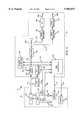
- FIG. 5is a block diagram of a receiver unit shown schematically in FIG. 1;
- FIG. 6is a flowchart of a software routine for adjusting the orientation of the satellite antenna shown in FIG. 4;
- FIG. 7is a flowchart of a software routine for driving motors used to orient the satellite antenna shown in FIG. 4;
- FIG. 8is a flowchart of a software routine for finely adjusting the orientation of the satellite antenna.
- FIG. 1illustrates an audiovisual broadcasting system in accordance with the invention.
- the broadcast systemincludes a central broadcasting station 50 having a program generator 52 connected to provide audiovisual and other program data to a transmitter 54.
- the program generator 52may comprise multiple digital video disks (DVD) or video servers which store compressed video data representing a plurality of pre-recorded video programs or movies, other recorded program sources (e.g. digital video tape), and/or sources of live or "turn-around" programming.
- the central broadcasting station 50has a network controller 56 that may be used to insert network commands into the program data generated by the program generator 52.
- the program and other dataare preferably transmitted in packets, using both frequency and time domain multiplexing. Other schemes (e.g. other packaging or transmission of digital or analog information) may also be used.
- the program datais processed in known manners to generate a plurality of RF uplinks comprising program data carriers.
- the transmitter 54transmits the program data carriers from the central broadcasting station 50 to one or more satellites 60. Downlink program data carriers, generally on offset frequencies, are then broadcast by the satellite 60 to a plurality of receiver units 70 disposed at various geographic locations remote from the central broadcasting station 50.
- One of the receiver units 70is shown in FIG. 1 to have an antenna system 72, such as a satellite dish, for receiving the program data carriers broadcast by the satellite 60, a receiver/decoder 74 connected to the antenna system 72 via a data line 75, and a global-positioning system (GPS) antenna 78 connected to the receiver/decoder 74 via a data line 79.
- GPSglobal-positioning system
- the receiver/decoder 74is connected to provide decoded program signals to a home video display 80, such as a television or other output device, via a line 82. Wireless links may also be used.
- the GPS antenna 78may be a conventional antenna that receives signals from at least three satellites 84, 86, 88 and, in combination with a GPS receiver described below, generates therefrom a position signal representing the precise geographic position of the antenna system 72, and thus of the receiver unit 70.
- the global positioning systemcan be used to determine geographic position within 100 meters or less for non-military applications.
- the receiver unit 70may be disposed at a fixed position.
- the GPS antenna 78is typically positioned outside the subscriber's dwelling and the receiver/decoder 74 is typically positioned inside the dwelling. In most cases, the GPS antenna 78 is positioned within ten meters or so of the receiver/decoder 74.
- the term "fixed" positionmeans a stationary position that remains fixed and is not moved for relatively long periods of time, such as months or years.
- the receiver unit 70may be a mobile unit, such as disposed in a mobile home.
- FIG. 4illustrates one possible embodiment of a portion of the antenna system 72 in the form of a satellite dish 90 (only a portion of which is shown) that is adjustable between a number of different orientations.
- the satellite dish 90has a central support shaft 92 which is integrally formed with or otherwise connected to a ball member 94 which is rotatably contained within an aperture formed in a spherical socket 96.
- the socket 96is integrally formed with or otherwise connected to a bracket 98 having a generally square internal aperture 100 to accommodate mounting the satellite dish 90 on a mounting post (not shown) having a square cross-sectional area.
- Other articulated mountsmay also be utilized.
- the bracket 98may be provided with an internal key 102 that is disposed within a slot in the mounting post (to facilitate proper orientation of the dish 90 on the mounting post), and the bracket 98 may be held in place on the mounting post with one or more screws (not shown).
- the particular manner in which the satellite dish 90 is supportedis not considered important to the invention, and other ways of mounting the satellite dish 90 could be used, with or without the use of a mounting bracket and/or mounting post.
- the orientation of the satellite dish 90may be adjusted via an adjustment mechanism having a first actuator 106 for moving the satellite dish 90 in a first direction, and a second actuator 108 for moving the dish 90 in a second direction generally perpendicular to the first direction, the actuators 106, 108 being connected to the support shaft 92 at two locations spaced preferably 90 degrees apart.
- Each actuator 106, 108has a rod 110 which is linearly is translatable into and out of a cylinder 112 under the control of a motor 114, such as a stepping motor.
- the translation of the rods 110may be accomplished via a screw or ball jack drive or any other conventional mechanism which translates rotation of the motors 114 into linear travel of the rods 110.
- Each of the cylinders 112is mounted to the socket 96 via a mounting arm 116 fixed to the cylinder 112 and a support arm 118 fixed to the socket 96 and pivotally connected to the mounting arm 116 at a pivot point 120.
- the end of each rod 110has a transverse rod 122 welded or otherwise connected to it.
- Each transverse rod 122is rotatably journalled within a pair of holes formed in a pair of brackets 124 connected to the support shaft 92.
- FIG. 5is a block diagram of the receiver unit 70 shown generally in FIG. 1.
- the motors 114which are used to position the satellite dish 90 of the antenna system 72 are driven by a pair of driver circuits 130, 132, and the motors 114 have a pair of shaft encoders 134, 136 associated therewith.
- the shaft encoders 134,136generate signals representing the degree of rotation of the shafts of the motors 114.
- Other open- or closed-loop systemsmay also be employed.
- the program data carriers received by the satellite antenna 90are provided to a low-noise block (LNB) circuit 138 which performs conventional block frequency shift functions.
- the LNBmay also select a subset of the received carriers (e.g. a single polarization) for output to the IRD.
- the resulting dataare provided to a tuner/demodulator 140 of the receiver/decoder 74 via the line 75.
- the tuner/demodulator 140which is activated by an authorization signal generated by an access controller 150 and transmitted to the tuner/demodulator 140 via a line 152, tunes the frequency band of the desired program data, demodulates the received IF signal from the LNB to generate e.g. a stream of digital data packets, and selects those packets corresponding to the desired program.
- the digital data packets(in the preferred embodiment) are provided from the tuner/demodulator 140 to a decoder 154 via a line 156.
- the decoder 154reformulates the data packets, removing portions of the data packets that do not represent actual programming, to generate a stream of digital data representing the audio and video portions of a program. That data stream is provided to a demultiplexer 158 which separates the audio and video portions of the digital data stream.
- the audio portions of the data streamare provided to an audio decoder 160 via a line 162.
- the audio decoder 160which may be a conventional MPEG (Motion Pictures Experts Group) audio decoder is connected to a digitalto-analog (D/A) converter 164, which converts the digital signal to an analog signal which is provided to the output device via a line 82a.
- D/Adigitalto-analog
- Other decoders appropriate to other output devicese.g. digital audio may similarly be employed.
- the video portions of the data stream generated by the demultiplexer 158are transmitted to a video decoder 170 via a line 172.
- the video decoder 160which may be a conventional MPEG decoder, decodes the data in a conventional manner and then transmits the decoded signal to a conventional NTSC encoder 174, which converts the digital signal to an analog NTSC video signal which is provided to the output device, e.g. analog home video display 80 (FIG. 1) via a line 82b.
- the output devicee.g. analog home video display 80 (FIG. 1) via a line 82b.
- other decoders appropriate to other output devicese.g. digital video
- the particular manner in which the program data are processed and decodedis not considered important to certain aspects of the invention, and other manners of processing the program data after they are received from the antenna system 72 may be used to convert the program data into a form usable with an analog or digital home video display.
- the data output from the tuner/demodulator 140 on the line 156are also provided to the access controller 150 and to an antenna controller 180 that is used to automatically adjust the orientation of the satellite dish 90.
- the GPS antenna 78periodically generates signals, based on communication signals preferably received from at least three GPS system satellites 84, 86, 88 (FIG. 1), which can be used to determine the particular geographic position of the GPS antenna 78, and thus of the receiver unit 70.
- the signals generated by the GPS antenna 78are transmitted to a position generator in the form of a GPS receiver 182, which generates a position signal based on the GPS signals received from the GPS antenna 78 and transmits the position signal to the access controller 150 and the dish controller 180 via a line 184.
- FIG. 2is a block diagram of the hardware components of the antenna controller 180 shown schematically in FIG. 5.
- the controller 180may be a conventional controller (either a single-chip controller or a multiple-chip controller such as a personal computer) having a computer program memory in the form of a read-only memory (ROM) 200, a microprocessor (MP) 202, a random-access memory (RAM) 204, an input/output (I/O) circuit 206, all of which are interconnected via an address/data bus 208.
- ROMread-only memory
- MPmicroprocessor
- RAMrandom-access memory
- I/Oinput/output
- FIG. 3is a block diagram of the hardware components of the access controller 150 shown schematically in FIG. 5.
- the controller 150may be a conventional controller having a computer program memory in the form of a ROM 210, a microprocessor 212, a RAM 214, an I/O circuit 216, all of which are interconnected via an address/data bus 218.
- FIG. 6is a flowchart of a computer program routine 220 performed by the dish controller 180 that may be used in certain embodiments to automatically adjust the orientation of the satellite dish 90.
- the satellite dish 90is moved to a reference or "home" orientation.
- Thispreferably relates to a known orientation of the antenna, such as a horizontal (or other known) elevation and a south (180 degrees) or other known azimuth.
- Thismay be accomplished in a conventional manner by providing each of the actuators 106, 108 (FIG. 4) with a limit switch or the like (e.g. optical, mechanical, magnetic, or other detector, not shown) used as a "home sensor” that detects when the rod 110 associated with that limit switch reaches a predetermined or home position.
- a limit switch or the likee.g. optical, mechanical, magnetic, or other detector, not shown
- the rods 110are continuously moved by the dish controller 180, via the driver circuits 130, 132 (FIG. 5) and motors 114 until the limit switches generate their home signals.
- the limit switchmay be provided in the form of a magnetically activated reed switch connected at a fixed position relative to the cylinders 112, and a magnet attached to the rods 110 which activates the reed switch when disposed adjacent the reed switch.
- the angular orientation of the satellite dish 90could be measured at all times, in which case one of the rods 110 could be assigned a first or X direction (e.g. altitude) and the other rod 110 could be assigned a second, perpendicular or Y direction (e.g. azimuth). In this case, at step 224 the X and Y orientations of the rods 110 could be reset to zero since the satellite dish 90 is in the home or reference orientation.
- X directione.g. altitude
- Y directione.g. azimuth
- the desired orientation of the satellite dish 90is determined based on the geographic position signal generated by the GPS receiver 182 and transmitted to the dish controller 180 via the line 184.
- the desired orientation of the dish 90could be determined by utilizing a lookup table stored in the memory of the dish controller 180. If a lookup table is used, each position signal that could be generated by the GPS receiver 182 could be provided in a first column of the lookup table, and for each position signal, the corresponding orientation of the satellite dish 90 in the X and Y directions could be stored. Thus, by locating the particular position signal generated by the GPS receiver 182 in the lookup table, the corresponding orientation of the satellite dish 90 in the X and Y directions could be retrieved.
- the desired orientation of the dish 90 in the X and Y directions stored in the lookup table for each geographic positioncould be empirically determined by determining the correct orientation of the dish 90 at each of a number of different geographic locations and translating each such orientation into the X and Y orientation data for storage in the lookup table. To limit the number of geographic locations at which the correct orientation needs to be measured, interpolation could be used. The stored values may take into consideration and compensate for any non-linearities in the operation of the mechanical system employed.
- the position signals stored thereincould be limited to certain geographic areas, such as relatively large urban areas.
- ranges of positions signalscould be stored. For example, if the position signal generated by the GPS receiver 182 has a component in degrees (or smaller increments) latitude and a component in degrees (or smaller increments) longitude, the dish controller 180 would search the lookup table for the latitude range into which the latitude component of the position signal fell and the longitude range into which the longitude component of the position signal fell, and would retrieve the satellite dish orientation data provided for the combination of those two ranges.
- steps 228 and 230in the embodiment illustrated the number of motor steps in the X and Y directions needed to move the satellite dish 90 to the orientation determined at step 226 are determined. For example, if the X and Y orientation data in the lookup table is stored in units of centimeters, steps 228 and 230 would be performed by multiplying the number of centimeters in each direction by the number of motor steps required to move the rods 110 a single centimeter. If the X and Y orientation data stored in the lookup table is stored in units corresponding to motor steps, no conversion is required and steps 228, 230 would be omitted.
- a drive routine described belowis performed to drive the motor 114 for the X direction the number of steps determined at step 228, and at step 234, the drive routine is performed to drive the motor 114 for the Y direction the number of steps determined at step 230.
- the satellite dish 90will have been moved to an orientation, based on the geographic position signal generated by the GPS receiver 182, in which the dish 90 is pointing generally at the satellite 60 (FIG. 1) which broadcasts the program data to the receiver unit 70.
- a fine adjustment routinedescribed in more detail below, may be performed at step 236 for both the X and Y directions.
- FIG. 7is a flowchart of a drive routine 240 performed by the dish controller 180, which was referred to above in connection with steps 232 and 234 of FIG. 6.
- the purpose of the drive routine 240is to drive the motors 114 (one at a time) a particular number of steps in a particular direction, to move the rods 110 back and forth.
- the drive routine 240drives the motors 114 no more than a certain number of steps at a time, that number being arbitrarily referred to as K. For example, if one of the motors 114 is to be driven a total of 240 steps and K is 25, the motor 114 would be driven 25 steps at a time until all the steps were moved.
- the dish controller 180checks the shaft encoder 134 or 136 for the motor 114 being driven to make sure that the motor 114 actually moved the requested number of steps.
- step 242if the number of steps left to be moved is greater than the predetermined number of K steps, the program branches to step 244 where the number of steps C that the motor 114 will be moved is set to K. Otherwise, the program branches to step 246 where C is set to the number of steps that are left to be moved.
- the motor 114 for the current direction(as specified by one of steps 232, 234) is moved C steps.
- the number of steps actually moved by the motor 114is checked, via the shaft encoder 134 or 136 associated with the motor 114 being driven, to make sure that the motor 114 actually moved C steps. If the motor 114 did not actually move C steps, the program branches to step 252 where the difference between the number of steps that were supposed to be moved and the number of actual steps is determined, and at step 254 the motor 114 is driven the number of steps determined in step 252.
- step 256the number of steps left is updated by decreasing the number of steps left by the number of steps C just moved.
- step 258if there are any steps left, the program branches back to step 242, where the process described above is repeated until the motor 114 for the current direction has been moved the requested number of steps.
- FIG. 8is a flowchart of a fine adjustment routine 270 that may be performed by the dish controller 180, which was referred to above in connection with step 236 of FIG. 6.
- the purpose of the fine adjustment routine 270is to optimally adjust the orientation of the satellite dish 90, after its initial orientation based on the position signal, so that the quality (e.g. signal strength, and/or error rate, and/or other quality factor(s)) of one or more broadcast program signals (e.g. data carrier(s) and/or encoded data) from the desired satellite(s) as received by the satellite dish 90 is maximized.
- Each time the fine adjustment routine 270 is performedit adjusts the orientation of the satellite dish 90 in a single direction.
- the fine adjustment routine 270may be performed once for each direction, or multiple times for each direction.
- the quality of the broadcast signal presented to the dish controller 180 via the line 156is determined.
- the signal via line 156permits controller 180 to react to the quality of e.g. the tuned and demodulated signal.
- other inputsmay be alternatively or additionally provided to controller 180, such as inputs directly from the LNB, from the decoder, etc. Error rates may be input from any portion of the IRD generating such data, e.g. from the IRD controller (not illustrated). All such embodiments are intended to be within the scope of the invention herein.
- the motor 114 for the current direction(e.g. X or Y) is moved an arbitrary number of steps T in the positive direction (e.g. +X direction).
- the quality of the broadcast signalis again determined to see if the new orientation of the satellite dish 90 resulted in better reception of the broadcast signal, which would occur in the case where the new quality of the broadcast signal determined at step 276 is greater than the old quality of the broadcast signal determined at step 272.
- step 278if the new orientation resulted in better reception, the program branches to step 280 where the dish controller 180 determines whether the fine adjustment of the satellite dish 90 is finished. That would be the case where, for example, the new quality of the broadcast signal is greater than the old quality by a inconsequential amount. This could be determined at step 280 by comparing the difference between the new and old qualities with a predetermined threshold value. If fine adjustment of the dish 90 is not finished, the program branches back to step 274.
- step 278if the initial movement of the satellite dish 90 did not result in better reception, meaning that the dish 90 was moved in the wrong direction, the program branches to step 282 where the motor 114 is moved T steps in the opposite or negative direction.
- step 284the quality of the broadcast signal is then determined, and the steps 282 and 284 are repeated until the increase in quality of the broadcast signal is inconsequential, as determined at step 286 and described above in connection with step 280.
- more than one quality factormay be monitored, alternatively or in combination.
- the quality factor of more than one signalmay be monitored, e.g. the strength of plural carriers, the error rates of plural channels, etc.
- the quality factor(s) of the same signal(s)are monitored at the varying antenna locations to minimize the effect of differences between signals, in other embodiments different signals may be monitored in different orientations.
Landscapes
- Engineering & Computer Science (AREA)
- Signal Processing (AREA)
- Physics & Mathematics (AREA)
- Astronomy & Astrophysics (AREA)
- General Physics & Mathematics (AREA)
- Multimedia (AREA)
- Variable-Direction Aerials And Aerial Arrays (AREA)
Abstract
Description
Claims (15)
Priority Applications (1)
| Application Number | Priority Date | Filing Date | Title |
|---|---|---|---|
| US08/898,226US5983071A (en) | 1997-07-22 | 1997-07-22 | Video receiver with automatic satellite antenna orientation |
Applications Claiming Priority (1)
| Application Number | Priority Date | Filing Date | Title |
|---|---|---|---|
| US08/898,226US5983071A (en) | 1997-07-22 | 1997-07-22 | Video receiver with automatic satellite antenna orientation |
Publications (1)
| Publication Number | Publication Date |
|---|---|
| US5983071Atrue US5983071A (en) | 1999-11-09 |
Family
ID=25409129
Family Applications (1)
| Application Number | Title | Priority Date | Filing Date |
|---|---|---|---|
| US08/898,226Expired - LifetimeUS5983071A (en) | 1997-07-22 | 1997-07-22 | Video receiver with automatic satellite antenna orientation |
Country Status (1)
| Country | Link |
|---|---|
| US (1) | US5983071A (en) |
Cited By (57)
| Publication number | Priority date | Publication date | Assignee | Title |
|---|---|---|---|---|
| WO2000018038A1 (en)* | 1998-09-21 | 2000-03-30 | Mobile Communications Holdings, Inc. | Antenna null |
| WO2001043428A1 (en)* | 1999-12-11 | 2001-06-14 | Koninklijke Philips Electronics N.V. | Tv receiver apparatus and related method |
| US6278405B1 (en)* | 1998-11-23 | 2001-08-21 | Samsung Electronics Co., Ltd. | AI antenna driving device and method for controlling the same |
| US6334218B1 (en)* | 1998-09-17 | 2001-12-25 | Handan Broadinfocom Co., Ltd. | Device for receiving satellite broadcast and a receiving method therefor |
| US6335855B1 (en)* | 1998-04-20 | 2002-01-01 | George Alexanian | Battery powered programmable remote switch controller |
| WO2001073955A3 (en)* | 2000-03-28 | 2002-03-21 | Lockheed Corp | System for access to direct broadcast satellite services |
| US6369942B1 (en) | 2000-06-27 | 2002-04-09 | Rick Hedrick | Auto-alignment tracking telescope mount |
| US20020071234A1 (en)* | 2000-10-25 | 2002-06-13 | George Alexanian | Battery powered programmable remote switch controller |
| US20020094823A1 (en)* | 2001-01-12 | 2002-07-18 | Kabushiki Kaisha Toshiba | Radio communication system |
| US6509934B1 (en)* | 1998-12-22 | 2003-01-21 | Mitsubishi Electric Research Laboratories, Inc. | Directing an antenna to receive digital television signals |
| WO2002061877A3 (en)* | 2001-02-01 | 2003-03-13 | Kathrein Werke Kg | Control device for a base station antenna |
| US20030083063A1 (en)* | 2001-11-01 | 2003-05-01 | Tia Mobile, Inc. | Easy set-up, vehicle mounted, in-motion tracking, satellite antenna |
| US6563471B2 (en)* | 2000-11-08 | 2003-05-13 | Gilat Satellite Networks, Ltd. | Automatic pointing antennae system |
| US20030119440A1 (en)* | 2001-12-21 | 2003-06-26 | Kumar Ramaswamy | Bi-directional communication apparatus |
| US20030156324A1 (en)* | 1998-10-26 | 2003-08-21 | Meade Instruments Corporation | Automated telescope with distributed orientation and operation processing |
| US20030181160A1 (en)* | 2002-03-21 | 2003-09-25 | Hirsch Andrew J. | Authentication and provisioning system for subscriber broadcasts |
| US6653981B2 (en) | 2001-11-01 | 2003-11-25 | Tia Mobile, Inc. | Easy set-up, low profile, vehicle mounted, satellite antenna |
| US6657589B2 (en) | 2001-11-01 | 2003-12-02 | Tia, Mobile Inc. | Easy set-up, low profile, vehicle mounted, in-motion tracking, satellite antenna |
| US6693587B1 (en) | 2003-01-10 | 2004-02-17 | Hughes Electronics Corporation | Antenna/feed alignment system for reception of multibeam DBS signals |
| US20040160375A1 (en)* | 2000-03-15 | 2004-08-19 | King Lael D. | Satellite locator system |
| US20040227655A1 (en)* | 2003-03-05 | 2004-11-18 | King Lael D. | Semi-automatic satellite locator system |
| US20040246174A1 (en)* | 2003-02-13 | 2004-12-09 | Frederic Lamour | Antenna system for links between mobile vehicles and airborne devices |
| US6944878B1 (en)* | 1999-07-19 | 2005-09-13 | Thomson Licensing S.A. | Method and apparatus for selecting a satellite signal |
| US20050235325A1 (en)* | 2004-04-20 | 2005-10-20 | O'donnell Laura J | Automatic reporting of antenna installation |
| US20050287968A1 (en)* | 2004-06-28 | 2005-12-29 | Funai Electric Co. Ltd. | Digital television broadcast signal receiver |
| US20050285784A1 (en)* | 2004-06-03 | 2005-12-29 | Interdigital Technology Corporation | Satellite communication subscriber device with a smart antenna and associated method |
| US20060003691A1 (en)* | 2004-06-25 | 2006-01-05 | Funai Electric Co., Ltd. | Broadcast receiver |
| US20060001956A1 (en)* | 1998-10-26 | 2006-01-05 | Baun Kenneth W | Systems and methods for automated telescope alignment and orientation |
| US6985190B1 (en)* | 1999-06-16 | 2006-01-10 | Thomson Licensing | Real-time signal strength display of terrestrial digital television signals |
| US6987487B2 (en) | 2001-02-19 | 2006-01-17 | Andrew Corporation | Antenna system |
| US7016643B1 (en)* | 2003-01-10 | 2006-03-21 | The Directv Group, Inc. | Antenna positioning system and method for simultaneous reception of signals from a plurality of satellites |
| US20060197713A1 (en)* | 2003-02-18 | 2006-09-07 | Starling Advanced Communication Ltd. | Low profile antenna for satellite communication |
| US20070146222A1 (en)* | 2005-10-16 | 2007-06-28 | Starling Advanced Communications Ltd. | Low profile antenna |
| US20070149121A1 (en)* | 2005-12-28 | 2007-06-28 | The Directv Group, Inc. | Command, control and communications with intelligent antennas |
| US20070297427A1 (en)* | 2004-09-22 | 2007-12-27 | Icube Corp. | Media Gateway |
| US20080018995A1 (en)* | 2006-07-21 | 2008-01-24 | Baun Kenneth W | User-directed automated telescope alignment |
| US7382448B1 (en) | 2005-03-16 | 2008-06-03 | Celestron Acquisition, Llc | Alignment system for observation instruments |
| US20080168492A1 (en)* | 2007-01-05 | 2008-07-10 | Meade Instruments Corp. | Celestial Viewing System With Video Display |
| US20080186242A1 (en)* | 2007-02-07 | 2008-08-07 | Sam Shuster | Enclosed mobile/transportable satellite antenna system |
| US7472409B1 (en) | 2000-03-28 | 2008-12-30 | Lockheed Martin Corporation | System for access to direct broadcast satellite services |
| US7557675B2 (en) | 2005-03-22 | 2009-07-07 | Radiacion Y Microondas, S.A. | Broad band mechanical phase shifter |
| US20090262033A1 (en)* | 2007-02-07 | 2009-10-22 | Lael King | Releasably mountable mobile/transportable motorized antenna system |
| US7663566B2 (en) | 2005-10-16 | 2010-02-16 | Starling Advanced Communications Ltd. | Dual polarization planar array antenna and cell elements therefor |
| US7671797B1 (en)* | 2006-09-18 | 2010-03-02 | Nvidia Corporation | Coordinate-based system, method and computer program product for adjusting an antenna |
| US8368611B2 (en) | 2009-08-01 | 2013-02-05 | Electronic Controlled Systems, Inc. | Enclosed antenna system for receiving broadcasts from multiple sources |
| US8405547B2 (en) | 2010-12-01 | 2013-03-26 | Mark Gianinni | Self-provisioning antenna system and method |
| ITBO20120649A1 (en)* | 2012-11-30 | 2014-05-31 | Teleco S P A | KIT FOR SATELLITE TELEVISION. |
| US8789116B2 (en) | 2011-11-18 | 2014-07-22 | Electronic Controlled Systems, Inc. | Satellite television antenna system |
| US8964891B2 (en) | 2012-12-18 | 2015-02-24 | Panasonic Avionics Corporation | Antenna system calibration |
| US9277271B2 (en)* | 2012-02-23 | 2016-03-01 | Zenith Electronics Llc | Wireless network antenna apparatus and method |
| US9583829B2 (en) | 2013-02-12 | 2017-02-28 | Panasonic Avionics Corporation | Optimization of low profile antenna(s) for equatorial operation |
| US10034183B2 (en) | 2016-02-26 | 2018-07-24 | Viasat, Inc. | Dynamic signal quality criteria for satellite terminal installations |
| US20180337451A1 (en)* | 2017-05-18 | 2018-11-22 | Daegu Gyeongbuk Institute Of Science And Technology | Device and method for automatically tracking broadcast satellite using global navigation satellite system (gnss) |
| US10177434B1 (en)* | 2016-12-23 | 2019-01-08 | X Development Llc | Parabolic reflector combined with phased array feed for long range communication |
| US10361771B2 (en) | 2016-01-22 | 2019-07-23 | Viasat, Inc. | Determining an attenuation environment of a satellite communication terminal |
| EP3480889A4 (en)* | 2016-06-30 | 2020-02-19 | Intellian Technologies Inc. | Pedestal apparatus having antenna attached thereto capable of biaxial motion |
| US11374650B2 (en) | 2016-05-27 | 2022-06-28 | Viasat, Inc. | Position-based access to satellite networks for satellite terminals |
Citations (18)
| Publication number | Priority date | Publication date | Assignee | Title |
|---|---|---|---|---|
| US4860352A (en)* | 1985-05-20 | 1989-08-22 | Satellite Financial Systems Corporation | Satellite communication system and method with message authentication suitable for use in financial institutions |
| US4993067A (en)* | 1988-12-27 | 1991-02-12 | Motorola, Inc. | Secure satellite over-the-air rekeying method and system |
| US5173708A (en)* | 1990-11-06 | 1992-12-22 | Aisin Seiki K.K. | Attitude control system for antenna on mobile body |
| US5243652A (en)* | 1992-09-30 | 1993-09-07 | Gte Laboratories Incorporated | Location-sensitive remote database access control |
| US5420592A (en)* | 1993-04-05 | 1995-05-30 | Radix Technologies, Inc. | Separated GPS sensor and processing system for remote GPS sensing and centralized ground station processing for remote mobile position and velocity determinations |
| US5428546A (en)* | 1992-10-16 | 1995-06-27 | Mobile Information Systems | Method and apparatus for tracking vehicle location |
| US5432542A (en)* | 1992-08-31 | 1995-07-11 | Television Computer, Inc. | Television receiver location identification |
| US5446465A (en)* | 1993-06-18 | 1995-08-29 | Diefes; Debra L. | Satellite location and pointing system for use with global positioning system |
| US5455592A (en)* | 1994-09-13 | 1995-10-03 | Litton Systems, Inc. | Method and apparatus for calibrating an antenna array |
| US5519405A (en)* | 1993-04-16 | 1996-05-21 | Masprodenkoh Kabushiki Kaisha | Direction adjustment indicator for a satellite radio wave receiving antenna |
| US5537102A (en)* | 1991-08-13 | 1996-07-16 | Electronic Monitoring Systems, Inc. | Apparatus and method for a system capable of remotely validating the identity of individual and their location |
| US5583514A (en)* | 1994-03-07 | 1996-12-10 | Loral Aerospace Corp. | Rapid satellite acquisition device |
| US5621793A (en)* | 1995-05-05 | 1997-04-15 | Rubin, Bednarek & Associates, Inc. | TV set top box using GPS |
| US5719918A (en)* | 1995-07-06 | 1998-02-17 | Newnet, Inc. | Short message transaction handling system |
| US5760819A (en)* | 1996-06-19 | 1998-06-02 | Hughes Electronics | Distribution of a large number of live television programs to individual passengers in an aircraft |
| US5790175A (en)* | 1996-06-19 | 1998-08-04 | Hughes Aircraft Company | Aircraft satellite television system for distributing television programming derived from direct broadcast satellites |
| US5790074A (en)* | 1996-08-15 | 1998-08-04 | Ericsson, Inc. | Automated location verification and authorization system for electronic devices |
| US5801751A (en)* | 1996-06-19 | 1998-09-01 | Hughes Electronics | Distribution of satellite television programs to passengers in an aircraft when it is out of range of the satellites |
- 1997
- 1997-07-22USUS08/898,226patent/US5983071A/ennot_activeExpired - Lifetime
Patent Citations (18)
| Publication number | Priority date | Publication date | Assignee | Title |
|---|---|---|---|---|
| US4860352A (en)* | 1985-05-20 | 1989-08-22 | Satellite Financial Systems Corporation | Satellite communication system and method with message authentication suitable for use in financial institutions |
| US4993067A (en)* | 1988-12-27 | 1991-02-12 | Motorola, Inc. | Secure satellite over-the-air rekeying method and system |
| US5173708A (en)* | 1990-11-06 | 1992-12-22 | Aisin Seiki K.K. | Attitude control system for antenna on mobile body |
| US5537102A (en)* | 1991-08-13 | 1996-07-16 | Electronic Monitoring Systems, Inc. | Apparatus and method for a system capable of remotely validating the identity of individual and their location |
| US5432542A (en)* | 1992-08-31 | 1995-07-11 | Television Computer, Inc. | Television receiver location identification |
| US5243652A (en)* | 1992-09-30 | 1993-09-07 | Gte Laboratories Incorporated | Location-sensitive remote database access control |
| US5428546A (en)* | 1992-10-16 | 1995-06-27 | Mobile Information Systems | Method and apparatus for tracking vehicle location |
| US5420592A (en)* | 1993-04-05 | 1995-05-30 | Radix Technologies, Inc. | Separated GPS sensor and processing system for remote GPS sensing and centralized ground station processing for remote mobile position and velocity determinations |
| US5519405A (en)* | 1993-04-16 | 1996-05-21 | Masprodenkoh Kabushiki Kaisha | Direction adjustment indicator for a satellite radio wave receiving antenna |
| US5446465A (en)* | 1993-06-18 | 1995-08-29 | Diefes; Debra L. | Satellite location and pointing system for use with global positioning system |
| US5583514A (en)* | 1994-03-07 | 1996-12-10 | Loral Aerospace Corp. | Rapid satellite acquisition device |
| US5455592A (en)* | 1994-09-13 | 1995-10-03 | Litton Systems, Inc. | Method and apparatus for calibrating an antenna array |
| US5621793A (en)* | 1995-05-05 | 1997-04-15 | Rubin, Bednarek & Associates, Inc. | TV set top box using GPS |
| US5719918A (en)* | 1995-07-06 | 1998-02-17 | Newnet, Inc. | Short message transaction handling system |
| US5760819A (en)* | 1996-06-19 | 1998-06-02 | Hughes Electronics | Distribution of a large number of live television programs to individual passengers in an aircraft |
| US5790175A (en)* | 1996-06-19 | 1998-08-04 | Hughes Aircraft Company | Aircraft satellite television system for distributing television programming derived from direct broadcast satellites |
| US5801751A (en)* | 1996-06-19 | 1998-09-01 | Hughes Electronics | Distribution of satellite television programs to passengers in an aircraft when it is out of range of the satellites |
| US5790074A (en)* | 1996-08-15 | 1998-08-04 | Ericsson, Inc. | Automated location verification and authorization system for electronic devices |
Cited By (111)
| Publication number | Priority date | Publication date | Assignee | Title |
|---|---|---|---|---|
| US6335855B1 (en)* | 1998-04-20 | 2002-01-01 | George Alexanian | Battery powered programmable remote switch controller |
| US7178160B2 (en) | 1998-06-05 | 2007-02-13 | Handan Broadinfocom Co., Ltd. | Device for receiving satellite broadcast and a receiving method therefor |
| US20020083457A1 (en)* | 1998-06-05 | 2002-06-27 | Handan Broad Infocom, A Republic Of Korea Corporation | Device for receiving satellite broadcast and a receiving method therefor |
| US20020007489A1 (en)* | 1998-06-05 | 2002-01-17 | Handan Broadinfocom | Device for receiving satellite broadcast and a receiving method therefor |
| US6334218B1 (en)* | 1998-09-17 | 2001-12-25 | Handan Broadinfocom Co., Ltd. | Device for receiving satellite broadcast and a receiving method therefor |
| WO2000018038A1 (en)* | 1998-09-21 | 2000-03-30 | Mobile Communications Holdings, Inc. | Antenna null |
| US6766166B1 (en)* | 1998-09-23 | 2004-07-20 | Mobile Communications Holdings, Inc. | Antenna null |
| US7092156B2 (en) | 1998-10-26 | 2006-08-15 | Meade Instruments Corporation | Automated telescope alignment and orientation method |
| US20060001956A1 (en)* | 1998-10-26 | 2006-01-05 | Baun Kenneth W | Systems and methods for automated telescope alignment and orientation |
| US20040047036A1 (en)* | 1998-10-26 | 2004-03-11 | Meade Instruments Corporation | Automated telescope alignment and orientation method |
| US7221527B2 (en) | 1998-10-26 | 2007-05-22 | Meade Instruments Corporation | Systems and methods for automated telescope alignment and orientation |
| US7079317B2 (en) | 1998-10-26 | 2006-07-18 | Meade Instruments Corporation | Automated telescope with distributed orientation and operation processing |
| US20060092508A1 (en)* | 1998-10-26 | 2006-05-04 | Baun Kenneth W | Systems and methods for aligning a telescope |
| US20030156324A1 (en)* | 1998-10-26 | 2003-08-21 | Meade Instruments Corporation | Automated telescope with distributed orientation and operation processing |
| US6278405B1 (en)* | 1998-11-23 | 2001-08-21 | Samsung Electronics Co., Ltd. | AI antenna driving device and method for controlling the same |
| US6509934B1 (en)* | 1998-12-22 | 2003-01-21 | Mitsubishi Electric Research Laboratories, Inc. | Directing an antenna to receive digital television signals |
| US6985190B1 (en)* | 1999-06-16 | 2006-01-10 | Thomson Licensing | Real-time signal strength display of terrestrial digital television signals |
| US20060033843A1 (en)* | 1999-06-16 | 2006-02-16 | Thomson Licensing S.A. | Real-time signal strength measurement and display of digital television signals |
| US7286190B2 (en) | 1999-06-16 | 2007-10-23 | Thomson Licensing | Real-time signal strength measurement and display of digital television signals |
| US6944878B1 (en)* | 1999-07-19 | 2005-09-13 | Thomson Licensing S.A. | Method and apparatus for selecting a satellite signal |
| US6809775B2 (en)* | 1999-12-11 | 2004-10-26 | Koninklijke Philips Electronics N.V. | TV receiver apparatus and related method |
| WO2001043428A1 (en)* | 1999-12-11 | 2001-06-14 | Koninklijke Philips Electronics N.V. | Tv receiver apparatus and related method |
| US20040160375A1 (en)* | 2000-03-15 | 2004-08-19 | King Lael D. | Satellite locator system |
| US6864846B2 (en) | 2000-03-15 | 2005-03-08 | Lael D. King | Satellite locator system |
| GB2378581A (en)* | 2000-03-28 | 2003-02-12 | Lockheed Corp | System for access to direct broadcast satellite services |
| US7472409B1 (en) | 2000-03-28 | 2008-12-30 | Lockheed Martin Corporation | System for access to direct broadcast satellite services |
| WO2001073955A3 (en)* | 2000-03-28 | 2002-03-21 | Lockheed Corp | System for access to direct broadcast satellite services |
| GB2378581B (en)* | 2000-03-28 | 2004-04-07 | Lockheed Corp | System for access to direct broadcast satellite services |
| US6369942B1 (en) | 2000-06-27 | 2002-04-09 | Rick Hedrick | Auto-alignment tracking telescope mount |
| US20020071234A1 (en)* | 2000-10-25 | 2002-06-13 | George Alexanian | Battery powered programmable remote switch controller |
| US6563471B2 (en)* | 2000-11-08 | 2003-05-13 | Gilat Satellite Networks, Ltd. | Automatic pointing antennae system |
| US20020094823A1 (en)* | 2001-01-12 | 2002-07-18 | Kabushiki Kaisha Toshiba | Radio communication system |
| WO2002061877A3 (en)* | 2001-02-01 | 2003-03-13 | Kathrein Werke Kg | Control device for a base station antenna |
| US7031751B2 (en) | 2001-02-01 | 2006-04-18 | Kathrein-Werke Kg | Control device for adjusting a different slope angle, especially of a mobile radio antenna associated with a base station, and corresponding antenna and corresponding method for modifying the slope angle |
| EP1455413A1 (en)* | 2001-02-01 | 2004-09-08 | Kathrein-Werke KG | Method of changing the down-tilt angle of an antenna, in particular of a base station antenna |
| CN100372175C (en)* | 2001-02-01 | 2008-02-27 | 凯特莱恩工厂股份公司 | Control device for adjusting different depression angles of mobile radio communication antenna of base station |
| US7366545B2 (en) | 2001-02-01 | 2008-04-29 | Kathrein Werke Kg | Control apparatus for changing a downtilt angle for antennas, in particular for a mobile radio antenna for a base station, as well as an associated mobile radio antenna and a method for changing the downtilt angle |
| US6987487B2 (en) | 2001-02-19 | 2006-01-17 | Andrew Corporation | Antenna system |
| US6657589B2 (en) | 2001-11-01 | 2003-12-02 | Tia, Mobile Inc. | Easy set-up, low profile, vehicle mounted, in-motion tracking, satellite antenna |
| US20030083063A1 (en)* | 2001-11-01 | 2003-05-01 | Tia Mobile, Inc. | Easy set-up, vehicle mounted, in-motion tracking, satellite antenna |
| US6653981B2 (en) | 2001-11-01 | 2003-11-25 | Tia Mobile, Inc. | Easy set-up, low profile, vehicle mounted, satellite antenna |
| US7123876B2 (en) | 2001-11-01 | 2006-10-17 | Motia | Easy set-up, vehicle mounted, in-motion tracking, satellite antenna |
| US7428403B2 (en) | 2001-12-21 | 2008-09-23 | Thomson Licensing | Bi-directional communication apparatus |
| US20030119440A1 (en)* | 2001-12-21 | 2003-06-26 | Kumar Ramaswamy | Bi-directional communication apparatus |
| US20030181160A1 (en)* | 2002-03-21 | 2003-09-25 | Hirsch Andrew J. | Authentication and provisioning system for subscriber broadcasts |
| US6693587B1 (en) | 2003-01-10 | 2004-02-17 | Hughes Electronics Corporation | Antenna/feed alignment system for reception of multibeam DBS signals |
| US7016643B1 (en)* | 2003-01-10 | 2006-03-21 | The Directv Group, Inc. | Antenna positioning system and method for simultaneous reception of signals from a plurality of satellites |
| US20040246174A1 (en)* | 2003-02-13 | 2004-12-09 | Frederic Lamour | Antenna system for links between mobile vehicles and airborne devices |
| US7629935B2 (en) | 2003-02-18 | 2009-12-08 | Starling Advanced Communications Ltd. | Low profile antenna for satellite communication |
| US20060197713A1 (en)* | 2003-02-18 | 2006-09-07 | Starling Advanced Communication Ltd. | Low profile antenna for satellite communication |
| US20060244669A1 (en)* | 2003-02-18 | 2006-11-02 | Starling Advanced Communications Ltd. | Low profile antenna for satellite communication |
| US7999750B2 (en) | 2003-02-18 | 2011-08-16 | Starling Advanced Communications Ltd. | Low profile antenna for satellite communication |
| US7768469B2 (en) | 2003-02-18 | 2010-08-03 | Starling Advanced Communications Ltd. | Low profile antenna for satellite communication |
| US7301505B2 (en) | 2003-03-05 | 2007-11-27 | King Controls | Semi-automatic satellite locator system |
| US20040227655A1 (en)* | 2003-03-05 | 2004-11-18 | King Lael D. | Semi-automatic satellite locator system |
| US7570222B2 (en) | 2003-03-05 | 2009-08-04 | King Controls | Semi-automatic satellite locator system |
| US6937199B2 (en) | 2003-03-05 | 2005-08-30 | Electronic Controlled Systems, Inc. | Semi-automatic satellite locator system |
| US20080136722A1 (en)* | 2003-03-05 | 2008-06-12 | King Lael D | Semi-automatic satellite locator system |
| US20060170603A1 (en)* | 2003-03-05 | 2006-08-03 | King Lael D | Semi-automatic satellite locator system |
| US8112779B2 (en) | 2004-04-20 | 2012-02-07 | The Directv Group, Inc. | Automatic reporting of antenna installation |
| US20050235325A1 (en)* | 2004-04-20 | 2005-10-20 | O'donnell Laura J | Automatic reporting of antenna installation |
| US20050285784A1 (en)* | 2004-06-03 | 2005-12-29 | Interdigital Technology Corporation | Satellite communication subscriber device with a smart antenna and associated method |
| US7633442B2 (en)* | 2004-06-03 | 2009-12-15 | Interdigital Technology Corporation | Satellite communication subscriber device with a smart antenna and associated method |
| US20060003691A1 (en)* | 2004-06-25 | 2006-01-05 | Funai Electric Co., Ltd. | Broadcast receiver |
| US7689161B2 (en)* | 2004-06-25 | 2010-03-30 | Funai Electric Co., Ltd. | Broadcast receiver with selective scanning and signal retrieval |
| US7761897B2 (en)* | 2004-06-28 | 2010-07-20 | Funai Electric Co., Ltd. | Digital television broadcast signal receiver |
| US20050287968A1 (en)* | 2004-06-28 | 2005-12-29 | Funai Electric Co. Ltd. | Digital television broadcast signal receiver |
| US20070297427A1 (en)* | 2004-09-22 | 2007-12-27 | Icube Corp. | Media Gateway |
| US8931027B2 (en)* | 2004-09-22 | 2015-01-06 | Icube Corp. | Media gateway |
| US7382448B1 (en) | 2005-03-16 | 2008-06-03 | Celestron Acquisition, Llc | Alignment system for observation instruments |
| US7557675B2 (en) | 2005-03-22 | 2009-07-07 | Radiacion Y Microondas, S.A. | Broad band mechanical phase shifter |
| US7994998B2 (en) | 2005-10-16 | 2011-08-09 | Starling Advanced Communications Ltd. | Dual polarization planar array antenna and cell elements therefor |
| US7595762B2 (en) | 2005-10-16 | 2009-09-29 | Starling Advanced Communications Ltd. | Low profile antenna |
| US7663566B2 (en) | 2005-10-16 | 2010-02-16 | Starling Advanced Communications Ltd. | Dual polarization planar array antenna and cell elements therefor |
| US20070146222A1 (en)* | 2005-10-16 | 2007-06-28 | Starling Advanced Communications Ltd. | Low profile antenna |
| US20100201571A1 (en)* | 2005-12-28 | 2010-08-12 | The Directv Group, Inc. | Command, control and communications with intelligent antennas |
| US7642960B2 (en)* | 2005-12-28 | 2010-01-05 | The Directv Group, Inc. | Command, control and communications with intelligent antennas |
| US8760346B2 (en) | 2005-12-28 | 2014-06-24 | The Directv Group, Inc. | Command, control and communications with intelligent antennas |
| US20070149121A1 (en)* | 2005-12-28 | 2007-06-28 | The Directv Group, Inc. | Command, control and communications with intelligent antennas |
| US20080018995A1 (en)* | 2006-07-21 | 2008-01-24 | Baun Kenneth W | User-directed automated telescope alignment |
| US7671797B1 (en)* | 2006-09-18 | 2010-03-02 | Nvidia Corporation | Coordinate-based system, method and computer program product for adjusting an antenna |
| US20080168492A1 (en)* | 2007-01-05 | 2008-07-10 | Meade Instruments Corp. | Celestial Viewing System With Video Display |
| US20080186242A1 (en)* | 2007-02-07 | 2008-08-07 | Sam Shuster | Enclosed mobile/transportable satellite antenna system |
| US20080246677A1 (en)* | 2007-02-07 | 2008-10-09 | Sam Shuster | Enclosed mobile/transportable satellite antenna system |
| US7595764B2 (en) | 2007-02-07 | 2009-09-29 | Wallace Technologies | Enclosed mobile/transportable satellite antenna system |
| US7679573B2 (en) | 2007-02-07 | 2010-03-16 | King Controls | Enclosed mobile/transportable motorized antenna system |
| US8816923B2 (en) | 2007-02-07 | 2014-08-26 | Electronic Controlled Systems, Inc. | Motorized satellite television antenna system |
| US20090262033A1 (en)* | 2007-02-07 | 2009-10-22 | Lael King | Releasably mountable mobile/transportable motorized antenna system |
| US8368611B2 (en) | 2009-08-01 | 2013-02-05 | Electronic Controlled Systems, Inc. | Enclosed antenna system for receiving broadcasts from multiple sources |
| US8405547B2 (en) | 2010-12-01 | 2013-03-26 | Mark Gianinni | Self-provisioning antenna system and method |
| US8789116B2 (en) | 2011-11-18 | 2014-07-22 | Electronic Controlled Systems, Inc. | Satellite television antenna system |
| US9118974B2 (en) | 2011-11-18 | 2015-08-25 | Electronic Controlled Systems, Inc. | Satellite television antenna system |
| US9277271B2 (en)* | 2012-02-23 | 2016-03-01 | Zenith Electronics Llc | Wireless network antenna apparatus and method |
| EP2738866A1 (en)* | 2012-11-30 | 2014-06-04 | Teleco S.P.A. | Satellite television kit |
| ITBO20120649A1 (en)* | 2012-11-30 | 2014-05-31 | Teleco S P A | KIT FOR SATELLITE TELEVISION. |
| US8964891B2 (en) | 2012-12-18 | 2015-02-24 | Panasonic Avionics Corporation | Antenna system calibration |
| US9583829B2 (en) | 2013-02-12 | 2017-02-28 | Panasonic Avionics Corporation | Optimization of low profile antenna(s) for equatorial operation |
| US10361771B2 (en) | 2016-01-22 | 2019-07-23 | Viasat, Inc. | Determining an attenuation environment of a satellite communication terminal |
| US12113605B2 (en) | 2016-01-22 | 2024-10-08 | Viasat, Inc. | Determining an attenuation environment of a satellite communication terminal |
| US10594386B2 (en) | 2016-01-22 | 2020-03-17 | Viasat, Inc. | Determining an attenuation environment of a satellite communication terminal |
| US12101651B2 (en) | 2016-02-26 | 2024-09-24 | Viasat, Inc. | Dynamic signal quality criteria for satellite terminal installations |
| US11109245B2 (en) | 2016-02-26 | 2021-08-31 | Viasat, Inc. | Dynamic signal quality criteria for satellite terminal installations |
| US11582623B2 (en) | 2016-02-26 | 2023-02-14 | Viasat, Inc. | Dynamic signal quality criteria for satellite terminal installations |
| US10609576B2 (en) | 2016-02-26 | 2020-03-31 | Viasat, Inc. | Dynamic signal quality criteria for satellite terminal installations |
| US10034183B2 (en) | 2016-02-26 | 2018-07-24 | Viasat, Inc. | Dynamic signal quality criteria for satellite terminal installations |
| US11374650B2 (en) | 2016-05-27 | 2022-06-28 | Viasat, Inc. | Position-based access to satellite networks for satellite terminals |
| US12040881B2 (en) | 2016-05-27 | 2024-07-16 | Viasat, Inc. | Position-based access to satellite networks for satellite terminals |
| US10957976B2 (en) | 2016-06-30 | 2021-03-23 | Intellian Technologies, Inc. | Pedestal apparatus having antenna attached thereto capable of biaxial motion |
| EP3480889A4 (en)* | 2016-06-30 | 2020-02-19 | Intellian Technologies Inc. | Pedestal apparatus having antenna attached thereto capable of biaxial motion |
| US10177434B1 (en)* | 2016-12-23 | 2019-01-08 | X Development Llc | Parabolic reflector combined with phased array feed for long range communication |
| US20180337451A1 (en)* | 2017-05-18 | 2018-11-22 | Daegu Gyeongbuk Institute Of Science And Technology | Device and method for automatically tracking broadcast satellite using global navigation satellite system (gnss) |
Similar Documents
| Publication | Publication Date | Title |
|---|---|---|
| US5983071A (en) | Video receiver with automatic satellite antenna orientation | |
| US5797083A (en) | Self-aligning satellite receiver antenna | |
| Debruin | Control systems for mobile satcom antennas | |
| EP2580810B1 (en) | Antenna orientation determination | |
| US6049306A (en) | Satellite antenna aiming device featuring real time elevation and heading adjustment | |
| JPH0224253Y2 (en) | ||
| AU686748B2 (en) | Apparatus and method for aligning a receiving antenna utilizing an audible tone | |
| US7215648B2 (en) | Apparatus and method for efficient live webcasting and network connectivity | |
| EP1456903B1 (en) | Antenna array for moving vehicles | |
| US6400315B1 (en) | Control system for electronically scanned phased array antennas with a mechanically steered axis | |
| US8106842B2 (en) | Ka/Ku antenna alignment | |
| JPH09298416A (en) | Antenna pointing direction setting support method and system | |
| US4710778A (en) | Satellite earth station | |
| WO2001003438A2 (en) | Mobile and hand-held broadcast video earth station terminals and methods for communicating with earth terminals via satellites | |
| EP0687114B1 (en) | Apparatus for providing audible instructions or status information for use in a digital television system | |
| US20080263601A1 (en) | Aeronautical satellite TV repeater | |
| US6268826B1 (en) | Method and apparatus for determining antenna pointing parameters in a satellite receiver | |
| PL309888A1 (en) | Satellite antenna base for multiple-satellite tv brodcast reception | |
| WO2000041341A1 (en) | Fixed ground track satellite constellation and user terminal | |
| US6208296B1 (en) | Method and apparatus for training a receiver on a source | |
| EP0757404A1 (en) | A satellite antenna alignment device | |
| JPS60242706A (en) | Device for adjusting direction of antenna of satellite broadcast receiver | |
| Tserenlkham et al. | Antenna tracking system for broadband portable terminal | |
| JPH04268474A (en) | Antenna device for satellite broadcasting service | |
| MXPA99009150A (en) | Method and apparatus for determining the antenna orientation parameters in a satel receiver |
Legal Events
| Date | Code | Title | Description |
|---|---|---|---|
| AS | Assignment | Owner name:HUGHES ELECTRONICS, CALIFORNIA Free format text:ASSIGNMENT OF ASSIGNORS INTEREST;ASSIGNORS:GAGNON, GREGORY J.;CROSBY, JEFFREY W.;REEL/FRAME:008653/0287 Effective date:19970717 | |
| AS | Assignment | Owner name:HUGHES ELECTRONICS CORPORATION, CALIFORNIA Free format text:ASSIGNMENT OF ASSIGNORS INTEREST;ASSIGNOR:HE HOLDINGS INC., DBA HUGHES ELECTRONICS, FORMERLY KNOWN AS HUGHES AIRCRAFT COMPANY;REEL/FRAME:008921/0153 Effective date:19971216 | |
| AS | Assignment | Owner name:HUGHES ELECTRONICS CORPORATION, CALIFORNIA Free format text:ASSIGNMENT OF ASSIGNORS INTEREST;ASSIGNOR:HE HOLDINGS INC., DBA HUGHES ELECTRONICS, FORMERLY KNOWN AS HUGHES AIRCRAFT COMPANY;REEL/FRAME:009004/0991 Effective date:19971216 | |
| STCF | Information on status: patent grant | Free format text:PATENTED CASE | |
| FEPP | Fee payment procedure | Free format text:PAYER NUMBER DE-ASSIGNED (ORIGINAL EVENT CODE: RMPN); ENTITY STATUS OF PATENT OWNER: LARGE ENTITY Free format text:PAYOR NUMBER ASSIGNED (ORIGINAL EVENT CODE: ASPN); ENTITY STATUS OF PATENT OWNER: LARGE ENTITY | |
| FPAY | Fee payment | Year of fee payment:4 | |
| FPAY | Fee payment | Year of fee payment:8 | |
| FPAY | Fee payment | Year of fee payment:12 |