US5983070A - Method and system providing increased antenna functionality in a RF distribution system - Google Patents
Method and system providing increased antenna functionality in a RF distribution systemDownload PDFInfo
- Publication number
- US5983070A US5983070AUS08/841,941US84194197AUS5983070AUS 5983070 AUS5983070 AUS 5983070AUS 84194197 AUS84194197 AUS 84194197AUS 5983070 AUS5983070 AUS 5983070A
- Authority
- US
- United States
- Prior art keywords
- signal
- cable
- constituent
- cables
- reference tone
- Prior art date
- Legal status (The legal status is an assumption and is not a legal conclusion. Google has not performed a legal analysis and makes no representation as to the accuracy of the status listed.)
- Expired - Lifetime
Links
Images


Classifications
- H—ELECTRICITY
- H03—ELECTRONIC CIRCUITRY
- H03D—DEMODULATION OR TRANSFERENCE OF MODULATION FROM ONE CARRIER TO ANOTHER
- H03D7/00—Transference of modulation from one carrier to another, e.g. frequency-changing
- H03D7/16—Multiple-frequency-changing
- H03D7/161—Multiple-frequency-changing all the frequency changers being connected in cascade
- H03D7/163—Multiple-frequency-changing all the frequency changers being connected in cascade the local oscillations of at least two of the frequency changers being derived from a single oscillator
- H—ELECTRICITY
- H03—ELECTRONIC CIRCUITRY
- H03L—AUTOMATIC CONTROL, STARTING, SYNCHRONISATION OR STABILISATION OF GENERATORS OF ELECTRONIC OSCILLATIONS OR PULSES
- H03L7/00—Automatic control of frequency or phase; Synchronisation
- H03L7/06—Automatic control of frequency or phase; Synchronisation using a reference signal applied to a frequency- or phase-locked loop
- H03L7/07—Automatic control of frequency or phase; Synchronisation using a reference signal applied to a frequency- or phase-locked loop using several loops, e.g. for redundant clock signal generation
- H—ELECTRICITY
- H03—ELECTRONIC CIRCUITRY
- H03L—AUTOMATIC CONTROL, STARTING, SYNCHRONISATION OR STABILISATION OF GENERATORS OF ELECTRONIC OSCILLATIONS OR PULSES
- H03L7/00—Automatic control of frequency or phase; Synchronisation
- H03L7/06—Automatic control of frequency or phase; Synchronisation using a reference signal applied to a frequency- or phase-locked loop
- H03L7/16—Indirect frequency synthesis, i.e. generating a desired one of a number of predetermined frequencies using a frequency- or phase-locked loop
- H03L7/22—Indirect frequency synthesis, i.e. generating a desired one of a number of predetermined frequencies using a frequency- or phase-locked loop using more than one loop
- H03L7/23—Indirect frequency synthesis, i.e. generating a desired one of a number of predetermined frequencies using a frequency- or phase-locked loop using more than one loop with pulse counters or frequency dividers
- H—ELECTRICITY
- H04—ELECTRIC COMMUNICATION TECHNIQUE
- H04B—TRANSMISSION
- H04B1/00—Details of transmission systems, not covered by a single one of groups H04B3/00 - H04B13/00; Details of transmission systems not characterised by the medium used for transmission
- H04B1/0003—Software-defined radio [SDR] systems, i.e. systems wherein components typically implemented in hardware, e.g. filters or modulators/demodulators, are implented using software, e.g. by involving an AD or DA conversion stage such that at least part of the signal processing is performed in the digital domain
- H04B1/0007—Software-defined radio [SDR] systems, i.e. systems wherein components typically implemented in hardware, e.g. filters or modulators/demodulators, are implented using software, e.g. by involving an AD or DA conversion stage such that at least part of the signal processing is performed in the digital domain wherein the AD/DA conversion occurs at radiofrequency or intermediate frequency stage
- H—ELECTRICITY
- H04—ELECTRIC COMMUNICATION TECHNIQUE
- H04B—TRANSMISSION
- H04B1/00—Details of transmission systems, not covered by a single one of groups H04B3/00 - H04B13/00; Details of transmission systems not characterised by the medium used for transmission
- H04B1/06—Receivers
- H04B1/16—Circuits
- H04B1/26—Circuits for superheterodyne receivers
- H—ELECTRICITY
- H04—ELECTRIC COMMUNICATION TECHNIQUE
- H04B—TRANSMISSION
- H04B3/00—Line transmission systems
- H—ELECTRICITY
- H04—ELECTRIC COMMUNICATION TECHNIQUE
- H04B—TRANSMISSION
- H04B7/00—Radio transmission systems, i.e. using radiation field
- H04B7/24—Radio transmission systems, i.e. using radiation field for communication between two or more posts
- H04B7/26—Radio transmission systems, i.e. using radiation field for communication between two or more posts at least one of which is mobile
- H04B7/2603—Arrangements for wireless physical layer control
- H04B7/2609—Arrangements for range control, e.g. by using remote antennas
- H—ELECTRICITY
- H03—ELECTRONIC CIRCUITRY
- H03D—DEMODULATION OR TRANSFERENCE OF MODULATION FROM ONE CARRIER TO ANOTHER
- H03D7/00—Transference of modulation from one carrier to another, e.g. frequency-changing
- H—ELECTRICITY
- H04—ELECTRIC COMMUNICATION TECHNIQUE
- H04W—WIRELESS COMMUNICATION NETWORKS
- H04W84/00—Network topologies
- H04W84/02—Hierarchically pre-organised networks, e.g. paging networks, cellular networks, WLAN [Wireless Local Area Network] or WLL [Wireless Local Loop]
- H04W84/10—Small scale networks; Flat hierarchical networks
- H04W84/14—WLL [Wireless Local Loop]; RLL [Radio Local Loop]
Definitions
- the present inventionrelates to the field of radio-frequency (RF) signal distribution, and in particular to an apparatus and method for distributing RF signals through low bandwidth infrastructures for re-transmission by antennas, wherein additional signals for controlling the antennas are transmitted over same low bandwidth infrastructures.
- RFradio-frequency
- RFradio frequency
- the firstis a set of antennas and associated accessories required for re-transmitting the RF signals inside a building.
- the secondis a cabling system, e.g., an optical fiber network, used for interconnecting the in-building antennas with a main antenna.
- the latteris usually installed on top of the building or at some location where the external RF signals can be easily received.
- the main antennacan be replaced by a direct interface with the RF network, e.g., in the basement.
- the cost of installing and maintaining such in-building distribution networksis very high.
- One of the major cost factorsis the cabling network. Not only must cable for carrying RF signals be installed but another set of cables and wiring is needed to incorporate any monitoring and diagnostic features into the system, e.g., the ability to control the gain of the re-transmitting antennas or check if the antennas are operational from a centralized building location.
- running new cables between various rooms, floors, or wings of a buildingis usually time-consuming and disruptive.
- desirable solutions to in-building RF distribution systemsshould incur minimal installation cost, require no special tooling (as necessitated, e.g., in fiber optic networks), and produce no undue disturbance in the building during installation and operation. It would also be advantageous for such distribution networks, including monitoring and diagnostic subsystems, to be consistent or implementable with common in-building cable infrastructure.
- the most common standard cable category 5 (10 base T) UTP cablefor example, has signal loss and cross talk properties that limit the bandwidth to approximately 0-100 MHz for distances ⁇ 100 m. Although these parameters suffice for LAN applications, they are clearly inadequate for the delivery of cellular and PCS signals to and from remote antenna sites. This is especially unfortunate in that 10 base T cable contains four twisted pair cables each of which, as suggested by the parent application cited above, could otherwise be used to transmit signals for radio communication or for antenna monitoring and control.
- the challengeis to transmit high frequency RF signals over the standard low bandwidth infrastructures, especially 10 base T cable.
- the common method of accomplishing this goalis to initially down-convert the band of the RF signal to an intermediate frequency (IF) which is within the bandwidth of the cable. Then, the IF signal is fed through the standard low bandwidth cable found in the building. At the remote antenna site the IF signal is up-converted to recover the original RF signal and the recovered RF signal is re-transmitted by the remote antenna.
- IFintermediate frequency
- a major problem encountered in implementing this solutioninvolves the stability of local oscillators. These provide the reference signals required by the mixers to down-convert and up-convert the signals. To ensure proper operation the local oscillators must generate a stable tone at the selected high RF frequency (e.g., 800 MHz). It is critical that the frequency of the two oscillators be matched to within at least the channel spacing of the RF signals. In fact, it is desirable that the oscillators be "locked" to each other to preserve the frequency of the RF signal band. This issue becomes even more crucial at higher frequencies, e.g., the PCS bandwidth centered around 2 GHz where the relative width of the communication channels is small in comparison to the carrier frequency.
- the selected high RF frequencye.g. 800 MHz
- the two solutions to this problemare to either use very stable oscillators (e.g., ⁇ 1 part per million stability), which are prohibitively expensive, or to distribute the oscillator tone from a central location.
- the second optionis not viable either, since the media under consideration does not have the bandwidth required for the implementation of such a system.
- the main purpose of the inventionis to gradually and reliably down-convert very high-frequency signal received, e.g., from satellites in orbit.
- U.S. Pat. No. 4,959,862 issued to Davidov et al.addresses a novel scheme for the delivery of FM modulated subcarriers over a fiber-optic link for cable television transmission (CATV).
- CATVcable television transmission
- Conventional CATV systemsuse vestigal sideband amplitude modulation (VSB-AM) for transmission of analog video channels to home users.
- FDM-FMfrequency division multiplexed frequency modulated
- FDM-FMfrequency division multiplexed frequency modulated
- Davidov et al.describe a method for the conversion of VSB-AM channels to FDM-FM channels before transmission over the fiber-optic link. After transmission, the FM signals are re-converted back to AM signals before transmission to the home.
- a 4 MHz "global reference"is distributed along with the FM signals to AM signals.
- the reference signalis high frequency and is distributed to the remote antenna sites for the purpose of FM to AM signal conversion. It is not a signal which is compatible with a system based on a limited and low bandwidth medium for transmitting RF signals.
- Davidov et al.emphasize the fact that this system uses a fiber-optic medium which is broadband.
- Davidov's system architectureit is not necessary to use the global reference, rather it is provided for convenience.
- the only advantage Davidov et al. derive from using a centralized oscillatoris the reduction of oscillator phase noise.
- the problemis solved by adding a radio frequency pilot tone to the up-converted signals before transmission.
- a local oscillatoris used to down-convert both the RF signal and the pilot tone. Any phase or frequency deviations of the local oscillator affect the RF signal and the pilot tone equally. Therefore, both signals can be used to cancel the phase and frequency variations, resulting in a clean recovered signal.
- This cancellation methodsolves the problem of local oscillator stability at the receiver.
- the disclosureis intended to solve a similar problem as the present invention, namely the stability of a remote oscillator, the method by which the problem is solved is quite different. Furthermore, the method does not describe, nor is it obvious, how one would implement this technique over a low-bandwidth medium, since the pilot tone is at a RF frequency.
- Another object of the inventionis to provide control and monitoring of re-transmitting antennas through the same standard in-building cabling transmitting RF signals.
- Another object of the inventionis to ensure that the system is highly efficient in its use of resources, simple to install and operate, and low-cost.
- Yet another object of the inventionto provide a method and a system for distributing RF signals in buildings which avoid oscillator instabilities which generate beat frequencies and related effects and lead to decreased link quality.
- the objects of the inventionare achieved by a unique system for transmitting a radio frequency (RF) signal in a RF bandwidth over a low bandwidth medium which has a transmission bandwidth below the RF bandwidth.
- the low bandwidth mediumis a standard unshielded twisted pair (UTP) cable belonging to common in-building infrastructure.
- the UTP cablecommonly consists of four twisted pair cables, two of which are used for bi-directional transmission of RF signals according to the invention, while the remaining two cables are used for antenna controlling and monitoring. In this manner the invention takes advantage of pre-existing infrastructure in a highly efficient and cost effective manner.
- the RF bandwidthis usually selected from the group of RF bandwidths used for cellular communications, cordless telephony, local RF communications, satellite television, interactive multi-media video, high bit-rate local area networks and the like. In these situations the RF bandwidth is narrower than the transmission bandwidth of the low bandwidth medium, typically UTP cable as noted above.
- the systemhas a unit, usually a main antenna or base station, for receiving the RF signal.
- a global reference oscillatorpreferably a very high stability oscillator such as a temperature-stabilized crystal oscillator, provides a global reference tone of high stability, e.g., ⁇ 1 part per million stability, at a frequency within the transmission bandwidth of the low bandwidth medium.
- the global reference oscillatoris located in a safe location inside a distribution hub and the global reference tone is delivered from there to the entire system, preferably over one of the four twisted pair cables in a UTP cable.
- a first local oscillatorpreferably a voltage-controlled oscillator (VCO) is controlled by a first adjustment signal derived from the global reference tone. With the aid of the first adjustment signal the first local oscillator generates a first RF reference tone of high stability.
- the main antenna and the first local oscillatorare connected to a first mixer, such that the first RF reference tone and the RF signal are delivered to this first mixer. From these two signals the mixer generates an intermediate frequency (IF) signal, which is fed through the low bandwidth medium, preferably one of the four twisted pair cables.
- the IF signalhas a frequency contained within the transmission bandwidth of the low bandwidth medium.
- a second local oscillatoris provided at a remote location, e.g., in a remote coverage area.
- the second local oscillatoris controlled by a second adjustment signal also derived from the global reference tone.
- the second local oscillatorgenerates a second RF reference tone of high stability at the same frequency as the first RF reference tone.
- a second mixeris also provided at the remote location and connected to the second local oscillator and to the low bandwidth medium.
- the second mixerreceives the second RF reference tone and the IF signal. By mixing these two signals the mixer recovers the original RF signal.
- this systemcan be extended to any number of remote locations, as will be necessary in a practical system which provides radio coverage to an entire building structure such as an office building or a shopping center.
- the method for deriving the first and second adjustment signalsrelies on a phase-locking circuit or a phase-locked loop (PLL).
- the global reference tonecan be delivered to the PLL in several ways. In particular, it can be delivered directly through a separate link, e.g., a short communication link if the global reference oscillator is positioned close to the oscillator in question. This is the case when both the local oscillator and the global reference oscillator are located in the same housing, such as a main hub. Otherwise, the global reference tone can be transmitted together with the IF signal through the low bandwidth medium, e.g., over the same twisted pair of a UTP cable.
- a filteris used for retrieving the global reference tone from the low bandwidth medium at the remote location. This function can be performed by a simple band-pass filter with its window set for the global reference tone.
- the PLL in this eventis located between the filter and the local oscillator at the remote location.
- the recovered RF signalcan be re-transmitted at one or many Iremote locations at a communication station.
- the communication stationscomprise local antennas with overlapping coverage areas.
- the systemis configured for bi-directional communication.
- a remote site antenna or communication stationis connected to the main antenna or base station through a network of low bandwidth UTP cable contained within a building structure.
- One twisted pair cable in the UTP cablecarries IF signals from the main antenna to the communication station, which up-converts the signals to RF signals and transmits the RF signals into the coverage area.
- the communication stationreceives RF signals from the coverage site, such as from a cellular telephone, and down-converts the RF signals to IF signals for transmission over a second twisted pair of the UTP cable to the main antenna.
- the remaining two twisted pair cablesare used to control and monitor the remote site antenna from a centralized location within the building structure.
- the voltage on a third twisted pair cablecan be used to control the gain of remote site antennas.
- the fourth twisted pair cablecan be used to monitor the antenna, from a centralized location, determining whether or not the remote site antenna is drawing power.
- the fourth twisted pair cablecan be used to deliver another communication service to the remote site.
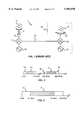
- FIG. 1is a schematic view of a typical prior art RF distribution system.
- FIG. 2is a diagram showing the typical RF bandwidth and a typical transmission bandwidth.
- FIG. 3is a diagram showing the transmission bandwidth and the bandwidth of the IF signal.
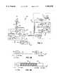
- FIG. 4is a schematic view of a simple RF distribution system according to the invention.
- FIG. 5Ais a diagram showing the stabilization of reference tones.
- FIG. 5Bis a diagram showing the relationship between the IF signal and the global reference tone.
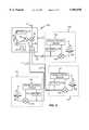
- FIG. 6is a schematic view of an RF distribution system according to the invention with multiple remote coverage sites.
- FIG. 7is a schematic view of another RF distribution system according to the invention.
- FIG. 8is a schematic view illustrating the overlap in coverage areas.
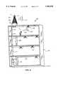
- FIG. 9is a three-dimensional view of the RF distribution system according to the invention adapted to a building structure.
- FIG. 10is a diagram showing typical 10 Base T in-building cables.
- FIG. 11is a schematic diagram of another RF distribution system according to the invention.
- FIG. 12is a schematic diagram of still another RF distribution system according to the invention.
- FIG. 13is a diagram illustrating a portion of a system of the invention using multi-mode optical fiber.
- FIG. 14is a graph of the Two Tone Test for the system of FIG. 13.
- FIG. 15is a diagram of an advantageous IF signal amplification method according to the invention.
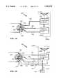
- FIG. 16Ais a diagram of a communication station for bi-directional communication over an UTP cable.
- FIG. 16Bis a diagram showing typical down- and up-conversion bandwidth channels for RF and IF signals.
- FIG. 17is a diagram of a connection between a 10 base T cable and remote site antenna with voltage controlled gain according to the invention.
- FIGS. 18 and 19are diagrams of a connection between a 10 base T cable and remote site antenna with testing means according to the invention.
- FIG. 1The salient features of the invention will be best appreciated after reviewing the typical prior art distribution system 10 for radio frequency (RF) signal 12 illustrated in FIG. 1.
- RF signal 12is in a bandwidth typically used for cellular communications or the like.
- FIG. 2indicates a RF bandwidth 30, spanning the range from 824 MHz to 894 MHz. This range is typical for RF signal 12 used in cellular communications.
- RF signal 12is received by base station or main antenna 14.
- Connection 16e.g., a coaxial cable, delivers RF signal 12 from antenna 14 to one of the inputs of a first mixer 18.
- the second input of mixer 18is connected to a first local oscillator 20.
- Oscillator 20provides an RF frequency tone which is utilized by mixer 18 to down-convert RF signal 12 to an intermediate frequency (IF) and to feed it through a low bandwidth medium 33, such as a standard, pre-installed cable.
- IFintermediate frequency
- FIG. 2better illustrates the relationships of the various signals and their bandwidths.
- the down-conversion of RF signal 12 from RF bandwidth 30yields an IF signal 32 contained in a transmission bandwidth 34.
- Transmission bandwidth 34ranges from 0 to 100 MHz, which is typical for low bandwidth media commonly installed in building structures.
- IF signal 32is transmitted through medium 33 to a remote location or site 36 delineated by a broken line.
- Site 36is usually a room inside a building structure or some other area in which RE coverage is desired.
- IF signal 32is received by a second mixer 38, which, with the aid of oscillator 40, up-converts IF signal 32 to recover original RF signal 12.
- a remote antenna 42is used to re-transmit RF signal 12 in remote site 36.
- distribution system 10 and other related prior art systemssuffer from instability of local oscillators 20 and 40 (unless very expensive oscillators are used).
- An RF distribution system 50 according to the invention and shown in FIG. 4avoids this disadvantage in a simple and effective manner.
- system 50has a main or base antenna 52 which receives RF signal 12.
- Antenna 52is connected by a communication link 54, e.g., a coaxial cable or any other link capable of transmitting RF signal 12 without undue distortions, to one of the inputs of a first mixer 56.
- the type of device selected as mixer 56can include any suitable single ended, balanced, double-balanced, double-double balanced or other mixer.
- a first local oscillator 58preferably a voltage-controlled oscillator (VCO), is connected to another input of mixer 56.
- a low bandwidth medium 60such as 10 base T cable, telephone wire, fiber-optic cable, unshielded or shielded cable, power cable, or any other low bandwidth in-building medium is connected to the output of mixer 56.
- Oscillator 58is typically a low-cost device which by itself produces an unstable RF reference tone.
- One output of oscillator 58is connected to mixer 56 and another output leads to a frequency divider 62.
- the function of divider 62is fulfilled by any frequency dividing device or circuit capable of dividing the received tone by an integer.
- the output of divider 62is further connected to one input of a phase comparator 64. Suitable comparators are well-known in the art.
- the second input of comparator 64is connected to a global reference oscillator 66.
- oscillator 66is housed in a separate housing unit or distribution hub 68.
- hub 68is installed in an area not exposed to excessive temperature fluctuations, vibrations, or other external influences. These conditions are frequently met inside buildings away from windows, doors, or other openings, e.g., in basements.
- the preferred embodimentemploys as oscillator 66 a temperature-stabilized crystal oscillator. Devices of this kind can achieve stability figures of about 1 part per million and are commercially available. The frequency of oscillator 66 will be discussed below.
- any element of system 50 in need of the tone from oscillator 66can be supplied with it through lines 70.
- one of lines 70connects oscillator 66 to the other input of comparator 64.
- the output of comparator 64is connected to a filter 72.
- a suitable low-pass loop filteris well-known in the art and can be constructed from commercially available components.
- the output of filter 72is connected to the control input of oscillator 58.
- system 50has a summing element or adding device 74 connecting one of lines 70 to low bandwidth medium 60.
- Device 74can combine signals already traveling through medium 60 with any additional signal, in this case the signal produced by oscillator 66. Devices capable of performing this operation are well-known in the art.
- medium 60is connected to a filter 78 and to a second mixer 80.
- Filter 78has a pre-set band-pass for selecting a specific frequency from the signals transmitted through medium 60.
- the output of filter 78is connected to one of the inputs of a phase comparator 82.
- the other input of comparator 82is connected to the output of a frequency divider 84, analogous to frequency divider 62, which, is connected to a second local oscillator 86.
- local oscillator 86is a voltage-controlled oscillator which produces an unstable RF reference tone.
- the output of comparator 82is hooked up through a filter 88 to the controlling input of oscillator 86.
- oscillator 86, divider 84, comparator 82 and filter 88form a phase-locking device or circuit 90, frequently also called a phase-locked loop (PLL).
- oscillator 58, filter 72, comparator 64 and divider 62also form a phase-locking circuit 92. Both circuits, 90 and 92, are analogous in construction and operation, as will be shown below.
- Remote coverage site 76has a re-transmitting unit 95, or RF antenna for re-transmitting RF signal 12 from mixer 80. Proper positioning of antenna 95 at site 76 to ensure RF coverage will be determined by the persons installing system 50 on a case by case basis.
- RF signal 12is contained in RF bandwidth 30 ranging from 824 MHz to 894 MHz. In practice, however, RF signal 12 can belong to other RF bandwidths, depending on the type of communication. Thus, RF bandwidth 30 can be selected from the group of RE bandwidths used for cellular communications, cordless telephony, local RF communications, satellite television, interactive multi-media video, high bit-rate local area networks, and the like. The characteristic feature shared by all these RF bandwidths is that they are higher than transmission bandwidth 34 of medium 60.
- Antenna 52delivers RF signal 12 via communication link 54 to first mixer 56.
- phase-locked loop 92delivers a first RF reference tone 96 (see FIG. 2) of high stability to mixer 56.
- first mixer 56responds to these two inputs by generating an IF signal 94, or, in other words, down-converting RF signal 12.
- the result of the down-conversion--IF signal 94--is shown in FIG. 3.
- the actual bandwidth of down-converted RF signal 12, i.e., IF signal 94,can vary as conditioned by available in-building infrastructure. At any rate, since-the output of first mixer 56 is connected to medium 60, IF signal 94 is transmitted or fed through medium 60.
- the down-conversion processitself depends on the stability of first RF reference tone 96 supplied to first mixer 56, and the former usually depends on the stability of first local oscillator 58. In this case, however, the output of oscillator 58 is a first RF reference tone 96 of high stability. This result is achieved in several steps with the aid of the remainder of phase-locking circuit 92 and global reference oscillator 66.
- the original output of oscillator 58which is an unstable RF reference tone 98 is fed to frequency divider 62.
- the inherent fluctuation of tone 98is evident from its wide spread of possible frequencies.
- Divider 62is set to divide tone 98 by an integer to derive an unstable IF reference tone 100, as shown. It is intended that unstable IF reference tone 100 match closely the frequency of a global reference tone 102 generated by global reference oscillator 66 residing in distribution hub 68. Also, unstable IF reference tone 100 as well as global reference tone 102 are contained within transmission bandwidth 34 of medium 60.
- global reference tone 102is in the middle of the bandwidth occupied by unstable IF reference tone 100. Furthermore, it is preferable that the bandwidth of IF reference tone 100, and consequently the frequency of global reference tone 102, lie outside the bandwidth of IF signal 94. This configuration avoids any potential interference between IF signal 94 and reference tone 100.
- the bandwidth of IF reference tone 100is below the bandwidth of IF signal 94 and centers around the frequency of global reference tone 102 equal to 8.0 MHz.
- Phase comparator 64receives at its two inputs unstable IF reference tone 100 and, through line 70, the highly stable global reference tone 102. In response to these two inputs comparator 64 generates at its output a first adjustment signal 104 representative of the phase mismatch or difference between unstable tone 100 and stable tone 102. Filter 72 clears adjustment signal 104 of high frequency noise, and ensures stability of the feedback loop. From filter 72 adjustment signal 104 passes to the control input of first local oscillator 58. There, adjustment signal 104 is used to fine-tune the oscillation frequency of oscillator 58.
- phase-locking circuit 92Thanks to the feedback nature of phase-locking circuit 92, the fine-tuning or trimming of oscillator 58 is performed continuously using the very stable global reference tone 102 as the benchmark. Consequently, the output of oscillator 58 is forced to generate first RF reference tone 96 of high stability.
- First mixer 56takes advantage of this high stability reference tone 96 to produce very accurately down-converted IF signal 32, which is then fed through medium 60.
- distribution hub 68is connected to summing element 74, which interfaces with medium 60.
- global reference tone 102 from oscillator 66is delivered to summing element 74.
- IF signal 94 already traveling through medium 60is combined with global reference tone 102 and sent through medium 60 to remote coverage site 76.
- No undesirable interferenceis created between IF signal 94 and tone 102 result, since their bandwidths do not overlap.
- global reference tone 102is efficiently forwarded to remote site 76 through the same medium as the useful signal.
- filter 78retrieves global reference tone 102 from medium 60. Meanwhile, IF signal 94 passes through to second mixer 80.
- Phase-locking circuit 90uses tone 102 to stabilize the output of second local oscillator 86.
- comparator 82produces a second adjustment signal 106 and delivers it through filter 88 to the control input of oscillator 86.
- the output of oscillator 86generates stable RF reference tone 96.
- Mixer 80uses stable RF reference tone 96 to up-convert IF signal 94 and recover RF signal 12 with minimal signal distortion. Then, RF antenna 95 receives RF signal 12 and re-transmits it throughout site 76.
- System 50is thus well-adapted to RF distribution in buildings and other structures using existing low bandwidth media such as conventional cables.
- the system resourcesare basic. Only one cost-intensive oscillator, namely global reference oscillator 66, is required to ensure proper up- and down-conversion of signals in this arrangement.
- the other essential elementsare simple, easy to install, and generally low-cost.
- voltage-controlled oscillatorssuch as oscillators 58 and 86 generating stable reference RF reference tone 96 at 800 MHz using 3.125 MHz as global reference tone 102 can achieve high stability at a very low cost.
- FIG. 6A more practical RF distribution system 110 according to the invention is illustrated in FIG. 6. Corresponding parts of this embodiment are designated with the same reference numbers as in the first embodiment.
- Communication link 54delivers RF signal 12 to a main hub 112.
- first mixer 56Housed inside main hub 112 is first mixer 56 and first local oscillator 58.
- Divider 62, comparator 64 and filter 72are connected and operate in the same manner as described above and are also housed in hub 112.
- global reference oscillator 66 and summing element 74are inside hub 112 as well. In this manner, all elements necessary to convert RF signal 12 to IF signal 94 are arranged in the same compact unit.
- Summing element 74is connected to three low bandwidth cables 114, which are routed to their respective remote coverage sites 116, 118, 120.
- Phased-locking circuits 122, 124, 126 and filters 128, 130, and 132are connected in the same manner and perform the same functions as filter 78 and circuit 90 in the previous embodiment.
- circuits 122, 124, 126 and filters 128, 130, and 132allow each remote site 116, 118, 120 to filter out global reference signal 102 and use it to produce a stable second RF reference signal 96.
- each remote site 116, 118, 120has its own second mixer 134, 136, and 138 for recovering RF signal 12 from IF signal 94. After recovery RF signal 12 is re-transmitted at each remote site 116, 118, 120 by a corresponding RF antenna 140, 142, 144.
- Distribution system 110is more compact and practical in some applications by virtue of using one single hub 112.
- hub 112have to ensure that the internal elements are protected.
- global reference oscillator 66has to be isolated in a manner to ensure stability of global reference tone 102.
- FIG. 7illustrates another RF distribution system 150 according to the invention.
- RF signal 12received by main antenna 52, is delivered to first mixer 56 to be down-converted to produce IF signal 94.
- Global reference oscillatoris housed separately in a distribution hub 152. From there global reference tone 102 is distributed through links 154 to network hubs 156 and 158, and to phase-locking loop 92.
- Network hubs 156 and 158contain multiple summing elements 74 which allow one to launch global reference tone 102 on many low bandwidth cables 160.
- cables 160constitute a network 162.
- Cables 160A-Dwhen viewed independently, form a tree network, while all cables 160 form two star networks with hubs 156 and 158 representing their centers.
- distribution system 150 of the inventioncan be adapted to any existing network of in-building cables.
- any star network, tree network, ring network or branch networkis suited for distributing RF signal 12 according to the invention.
- links 154do not need to be part of the network infrastructure if other media for distributing global reference signal 102 are deemed convenient by the system designer.
- global reference tone 102can be distributed through fiber-optic links, or AC power lines.
- FIG. 8shows a particularly advantageous aspect of the invention.
- Two remote coverage sites 170 and 172have corresponding RF antennas 174 and 176 for re-transmitting RF signal 12.
- IF signal 94is fed through a low bandwidth medium, in this case power cables 178 and 180.
- Units 182 and 184contain all the elements discussed above necessary for recovering RF signal 12 from IF signal 94 according to the invention.
- the region where this happensis hatched and designated by reference numeral 186.
- overlap in coverage of adjacent sitesis desirable because it guarantees complete coverage.
- a user equipped with an RF receiver (not shown) and positioned in region 186will receive RF signal 12 from both antennas 174 and 176.
- ⁇ ffrequency difference between RF signal 12 coming from antenna 174 and the same RF signal 12 arriving from antenna 176.
- This frequency differencetypically about ⁇ 500 Hz
- the beat frequencycan impair the functioning of the electrical components and introduce spurious signals.
- RF distribution systems used for data transfercan experience higher bit error rates (BER) and other degrading effects.
- RF distribution systemscan recover RF signal 12 with no frequency shift at all.
- RF signal 12 radiated from antenna 174 and from antenna 176will have the same frequency and not induce any beats.
- FIG. 9illustrates an RF distribution system 190 according to the invention used in a building structure 192.
- system 190is bi-directional, i.e., RF antennas 194 installed in various locations throughout structure 192 can re-transmit and receive RF signals 12.
- transmitted RF signalsare designated by 12A and received RF signals are indicated by 12B.
- a main antenna 196 mounted on the roof of structure 192can also transmit and receive RF signals 12A and 12B.
- System 190utilizes in-building low bandwidth network including cables 198, 200, 202, 204, and wiring closets 206 and 208 to distribute RF signal 12.
- wiring closet 208houses a distribution hub 210.
- the lattersupplies global reference tone 102 from a temperature-stabilized crystal oscillator serving as the global reference oscillator (not shown). Protection of hub 210 from external influences is ensured by virtue of location of closet 208 on the ground floor and away from openings such as doors or windows.
- cables 198, 200, 202, 204may constitute a pre-existing network which can not be extensively modified by the designer without expensive re-routing work.
- cables 198, 200, 202, 204are standard AC power cables which are truly ubiquitous even in old structures. The choice of AC power cables will allow one to distribute RF signals in virtually any environment without altering the in-building cabling, thus providing an ultra-low-cost RF distribution network.
- An additional advantage of using AC power linesis that the power for operating antennas 194 and any other necessary electronics (not shown) can be provided through cables 198, 200, 202, and 204 simultaneously with the IF signal.
- AC power linesare pre-installed, the designer of the RF distribution system will encounter some limitations. Indeed, in some rooms the locations of antennas 194 may be imposed by the infrastructure.
- FIG. 10illustrates the most common low bandwidth medium 220 found inside buildings.
- medium 220is a cable consisting of four twisted pairs 222, 224, 226, 228 or wire pairs. These can all be used for distributing signals for cellular communications, cordless telephony, local RF communications, satellite television, interactive multi-media video, or high bit-rate local area networks.
- FIG. 11illustrates schematically yet another RF distribution system 230 according to the invention.
- Main antenna 232is positioned on top of a building 234 to receive and transmit RF signals 12A and 12B.
- System 230consists of three star networks 238A, 238B, 238C, one per floor, individually fed from antenna 232.
- Networks 238A, 238B, 238Chave RF antennas 240 and independent hubs 242A, 242B, 242C for housing the essential components discussed above.
- FIG. 12illustrates another advantageous RF distribution system 250 inside same building 252.
- System 250takes advantage of a pre-installed private branch exchange 254 (PBX) and does away with a main antenna as the unit for receiving and re-transmitting RF signals 12A and 12B.
- PBXprivate branch exchange 254
- RF signals 12A and 12Bare delivered to PBX 254 and received from it by any suitable high bandwidth medium (not shown).
- RF signals 12Bare fed by PBX 254 to hubs 258A, 258B, 258C of three star networks 256A, 256B, 256C.
- RF signals 12Aare received from star networks 256A, 256B, 256C and sent back to PBX 254, which re-transmits them via the high bandwidth medium.
- PBX systemsare widespread, this embodiment is very practical. No additional cables need to be routed from any external RF antennas in this case.
- PBX systemsare found in many locations and are frequently pre-wired for indoor within one or more building structures, and, in some cases, outdoor operation as well. Few modifications will be required to install an RF distribution system according to the invention in this manner.
- FIG. 13illustrates a portion of yet another system 260 according to the invention.
- a low bandwidth medium 262in this case a multi-mode fiber optic cable, connects a LED (Light Emitting Diode) unit 264 to a low-speed analog detector 266 at a remote site 270. Because the transmission bandwidth of optic cable 262 required for this invention is below 100 MHz the length of cable 262 can exceed 1 km. The ability to cover such distances renders the embodiment particularly useful in shopping centers and other structures covering large areas.
- Same mixer 56 as in FIG. 4delivers IF signal 94 to LED unit 264 via low bandwidth medium 268.
- Medium 268may belong to a pre-installed network, e.g., AC power mains or telephone wires.
- LED unit 264exhibit an excellent response at low frequencies, in particular within the transmission bandwidth of medium 262, ( ⁇ 100 MHz), and no response at higher frequencies, e.g., 1 GHZ.
- LED unit 264is well-suited for feeding IF signal 94 through medium 262.
- Conventional optical systemsuse lasers and single-mode optical fibers, both of which are expensive, to send signals at various frequencies. This embodiment is very low cost in comparison with conventional systems and very efficient in the desired frequency range.
- FIG. 14shows the results of a standard Two Tone Test for LED unit 264 operating at 1.3 um and 1 km long cable 262.
- FIG. 15shows an advantageous addition to a portion of a system 280 according to the invention.
- System 280uses a summing element 288 for adding global reference tone 102 to IF signal 94, as discussed above, and feeding both through a network 290 consisting of low bandwidth cables 286.
- Two standard amplifiers 282 and 284 for amplifying signals within transmission bandwidth 34are connected to cables 286.
- amplifiers 282 and 284amplify IF signal 94 while it passes through cables 286. If desired, both or one of amplifiers 282, 284 can also amplify global reference tone 102.
- amplifying signals at lower frequenciesis simpler and less costly than amplifying RF frequency signals.
- This "repeater function"can be incorporated in any of the above embodiments by installing suitable low frequency amplifiers ( ⁇ 100 MHz) at frequencies corresponding to the IF signals and/or to the global reference tone.
- UTP cable 220contains 4 twisted pair cables 222, 224, 226, 228, as does the unshielded Category 5 twisted-pair 10 Base T cable typically employed for Ethernet data transmission.
- UTP cable 220contains 4 twisted pair cables 222, 224, 226, 228, as does the unshielded Category 5 twisted-pair 10 Base T cable typically employed for Ethernet data transmission.
- Base T cabletypically employed for Ethernet data transmission.
- FIG. 16Adepicts a schematic for a remote site antenna unit 359 for frequency duplex operation suitable for bi-directional communication over a UTP cable.
- FIG. 16Ashows an antenna 360 of unit 359 attached to a corresponding antenna component block 362.
- the component block 362in turn has a down-conversion connection 364 for feeding signals received by remote site antenna 360 into twisted pair 224 contained in UTP cable 220.
- component block 362has an up-conversion connection 366 for accepting signals from twisted pair 226 which will ultimately be re-transmitted by remote site antenna 360.
- unit 359has a receiving and re-transmission means other than an antenna 360, e.g., block 362 feeds directly into an electronic device such as a speaker phone or computer.
- remote site antenna unit 359is more broadly referred to as a communication station.
- FIG. 16Billustrates two separate frequency channels reserved, respectively, for signals to be received and signals to be transmitted by antenna 360.
- a RF down-conversion channel 380contains a RF down-conversion signal 382
- a RF up-conversion channel 384contains a RF up-conversion signal 386.
- the bandwidth of RF down-conversion channel 380is 824 MHz-849 MHz or 25 Mhz; similarly, the bandwidth of RF up-conversion channel 384 is 869 MHz-894 MHz, or also 25 MHz. Again these numbers are for illustrative purposes and other embodiments can obviously operate with channels of different bandwidths.
- antenna component block 362in passing RF down-conversion signal 382 from antenna 360 to twisted pair 224 is as follows.
- RF down-conversion signal 382is received by antenna 360 and fed to a frequency duplexer 388 within block 362.
- Duplexer 388routes all signals in down-conversion channel 380 including RF down-conversion signal 382 through an upper connection 390.
- the RF down-conversion signal 382is then amplified by amplifier G 1 and sent to a first mixer 392.
- Mixer 392combines RF down-conversion signal 382 with a highly stable RF reference tone 394 received from a phase-locked loop 396 and down-converts the RF down-conversion signal 382 to a lower frequency IF down-conversion signal 398.
- the resulting IF down-conversion signal 398is contained in an IF down-conversion channel 400 of sufficiently low bandwidth as to be suitable for transmission over a low bandwidth medium such as a twisted pair cable.
- the IF down-conversion signal 398exits antenna component block 362 through down-conversion connection 364 and enters into twisted pair 224 for further transmission.
- phase-locked loop 396takes as input a global oscillator tone 402 and outputs a highly stable RF reference tone 394.
- Global oscillator tone 402can be delivered in any number of ways to phase-locked loop 396.
- a preferred approachis to send the global oscillator tone 402 over the same twisted pair 226 which carries signals to be transmitted by antenna 360. This configuration is illustrated in FIG. 16A.
- Both global oscillator tone 402 and an IF up-conversion signal 404are fed from twisted pair 226 into antenna component block 362 through up-conversion connection 366.
- a filter 412then removes the global oscillator tone from connection 366 and feeds the tone to phase-locked loop 396.
- Loop 396in turn outputs highly stable RF tone 394 for up-conversion at first mixer 392 and for down-conversion at a second mixer 408.
- Up-conversion of signals sent over twisted pair 226is accomplished in antenna unit 359 as follows.
- IF up-conversion signal 404 contained in an IF up-conversion bandwidth 406is fed from twisted pair 226 into up-conversion connection 366, amplified by amplifier G 3 , and mixed with RF reference tone 394 in second mixer 408.
- the output of second mixer 408, an RF up-conversion signal 386is amplified by amplifier G 4 and fed through a lower connection 410 to duplexer 388.
- duplexer 388feeds RF up-conversion signal 386, and any other signals contained in RF up-conversion channel 384, to antenna 360 for transmission.
- FIG. 16AThere are several other embodiments or variations producing bi-directional communication according to the present invention besides that shown in FIG. 16A. Obviously, one could set up, side-by-side, two copies of a uni-directional system, each as taught in the earlier part of this description, but with their directions of communication reversed. Thus a remote coverage site would have two antennas, one for reception and one for transmission, and each antenna would have its own phase-locked-loop; further each uni-directional system would have its own global oscillator. FIG. 16A teaches that many of the components can be efficiently shared between the up- and down-conversion portions.
- FIG. 17, FIG. 18 and FIG. 19illustrate some especially advantageous features that can be incorporated in a distribution system over UTP cable 220.
- FIG. 17depicts a RF distribution system for a building structure 355 using a network of UTP cable 220 to distribute RF signals 386 received from a main antenna 302.
- RF signals 386are re-transmitted from remote site antenna units 359A and 359B into remote coverage sites 300 and 330, respectively.
- the systemis bi-directional; RF signals 382 received by remote site antenna units 359A and 359B from user transmission units 303A, 303B are directed back to main antenna 302 and re-transmitted.
- FIG. 18 and FIG. 19show the connections between antenna units 359A and 359B and UTP cable 220.
- Typical radio distribution for bi-directional communicationrequires the use of 2 of the 4 twisted pair cables 222, 224, 226, 228 of UTP cable 220; one pair 226 for (up-conversion or downlink) transmission of signals into remote sites 300, 330, and one pair 224 for (down-conversion or uplink) transmission out.
- the remaining two twisted pair cables 222, 228can be used to provide control and/or monitoring of remote site antenna units 359A, 359B from a centralized location 350 within building structure 355. In this way monitoring and adjusting of remote site antenna units 359A, 359B can be performed quickly and efficiently.
- a centralized locationsuch as location 350, is a building location (or other location within a structure through which RF distribution is desired) where cable connections from remote coverage sites come together. This location is highly dependent on the nature of a given building structure and the nature of pre-existing cable. One skilled in the art can readily determine a suitable location on a case-by-case basis, supplying and installing additional cable when and where necessary. Although main building structures could best be served by a plurality of centralized locations each controlling subsets of coverage site antennae, a proposition whose details are obvious in light of the present description, for concreteness we focus on the building structure 355 of FIG. 17 with centralized location 350 for the remainder of this detailed description.
- FIG. 18depicts a remote coverage site 300 of structure 355 of FIG. 17 serviced by UTP cable 220.
- twisted pair 226 of cable 220transmits IF up-conversion signal 404 through up-conversion connection 366 and into an antenna component block 362A for conversion to RF signal 386 and subsequent re-transmission by antenna 360A.
- Another twisted pair 224is connected to down-conversion connection 364.
- RF down-conversion signal 382 received by antenna 360Ais converted to IF down-conversion signal 398 within antenna component block 362A and passed through down-conversion connection 364 to twisted pair 224 within cable 220.
- Antenna component block 362Acontains all the circuitry of antenna component block 362 of FIG. 16.
- the gain of block 362Ais provided by amplifiers G 1 , G 2 , G 3 , G 4 which preferably increase (although could be arranged to decrease) the strength of signals received from up-conversion connection 366 prior to transmission into coverage site 300 and similarly increases (decreases) the strength of signals received from coverage site 300 prior to transmission through down-conversion connection 364.
- Antenna unit 359Afurther comprises a voltage controlled attenuator 312 which adjusts the level of signal transmission gain.
- the attenuator 312is situated between antenna component block 362A and antenna 360A.
- the level of attenuation provided by attenuator 312is controlled by a voltage V on a connection 314 to twisted cable 222.
- Voltage Vin turn can readily be controlled at centralized location 350 by means obvious to one skilled in the art.
- the individual antenna gain, or equivalently, the extent of site coverageis controlled from centralized location 350 in the building 355.
- the entire radio frequency distribution systemcan be conveniently adjusted and optimized from centralized location 350.
- finer controlcan be attained by using two twisted pairs, one pair to control up-conversion gain and one pair to control down-conversion gain.
- a voltage controlled attenuatoris placed on down-conversion connection 364 and one is place on up-conversion connection 366 (not shown).
- the voltage on twisted pair 228is used to control the attenuator on connection 366, while the voltage on twisted pair 222 controls the attenuator on connection 364. In this way the up- and down-conversion gains can individually be adjusted from a centralized location.
- antenna gainis a highly desirable characteristic to adjust from centralized location 350, once given the above description a skilled artisan can readily conceive of many other features at a remote site 300 which can be similarly controlled or adjusted in a useful manner.
- the remaining twisted pair 228 of FIG. 18can also be used to adjust or control any one of these features. These features are not necessarily limited to properties of antenna unit 359A.
- a twisted pair 228could be used as a switch for any device in the remote site 300.
- remaining twisted pair cablescan carry other communication services. Examples include data LAN (local area network), video, wired voice, and other wireless services such as PCS (personal communications systems) and wireless LANs.
- a test signal 349A created by a test means 348is directed to antenna component block 362B.
- Antenna component block 362Bwhen operable responds to the test by sending a predetermined affirmative signal 341 back to centralized location 350 via connection 340 to twisted pair 222.
- Test means 348can be in the form of an electronic device constructed by techniques known in the art and installed at remote coverage site 330 either permanently, or perhaps temporarily for the purpose of system set-up diagnostics and testing.
- a test signal 349Bis initiated at centralized location 350 and travels over another twisted pair cable 228 through connection 344 to antenna unit 359B.
- a human or computerized monitorcan test the operability of each remote site antenna from a centralized location 350.
- a very simple embodiment of this testing schemeis to have the voltage on twisted pair 222 continually indicate whether antenna component block 362B is drawing power; a higher voltage on twisted pair 222 indicating the affirmative, lower or zero voltage, the negative. In this case, twisted pair 228 is not needed for testing and could be used for other purposes such as adjusting antenna gain.
- the test meanscould be a generator producing a RF test signal which antenna 360B receives and transmits to the centralized location 350 through the down-conversion connection 364 and twisted pair cable 224, or alternatively through connection 340 and twisted pair cable 222.
- the strength of the test signal arriving at the centralized locationis then indicative of the antenna gain.
- the gainthen can be adjusted appropriately if needed, preferably, by adjusting the voltage on a remaining twisted pair cable which in turn controls the gain of the antenna as described above.
- the presented embodimentsare only illustrative of some of the many types of networks of UTP cable which can be used according to the invention to distribute RF signals while simultaneously supporting antenna functionality and/or alternate communication services. Every particular network will be different, as conditioned by pre-existing infrastructure. Adaptations to particular bandwidths and frequencies, (e.g., for IF signals) will be made depending on application.
Landscapes
- Engineering & Computer Science (AREA)
- Computer Networks & Wireless Communication (AREA)
- Signal Processing (AREA)
- Power Engineering (AREA)
- Mobile Radio Communication Systems (AREA)
Abstract
Description
Claims (27)
Priority Applications (3)
| Application Number | Priority Date | Filing Date | Title |
|---|---|---|---|
| US08/841,941US5983070A (en) | 1996-04-19 | 1997-04-08 | Method and system providing increased antenna functionality in a RF distribution system |
| PCT/US1998/006979WO1998045956A1 (en) | 1997-04-08 | 1998-04-07 | Rf distribution system providing fixed wireless local loop service and increased antenna functionality |
| US09/095,084US6157810A (en) | 1996-04-19 | 1998-06-09 | Distribution of radio-frequency signals through low bandwidth infrastructures |
Applications Claiming Priority (2)
| Application Number | Priority Date | Filing Date | Title |
|---|---|---|---|
| US63536896A | 1996-04-19 | 1996-04-19 | |
| US08/841,941US5983070A (en) | 1996-04-19 | 1997-04-08 | Method and system providing increased antenna functionality in a RF distribution system |
Related Parent Applications (1)
| Application Number | Title | Priority Date | Filing Date |
|---|---|---|---|
| US63536896AContinuation-In-Part | 1996-04-19 | 1996-04-19 |
Related Child Applications (1)
| Application Number | Title | Priority Date | Filing Date |
|---|---|---|---|
| US09/095,084Continuation-In-PartUS6157810A (en) | 1996-04-19 | 1998-06-09 | Distribution of radio-frequency signals through low bandwidth infrastructures |
Publications (1)
| Publication Number | Publication Date |
|---|---|
| US5983070Atrue US5983070A (en) | 1999-11-09 |
Family
ID=27092360
Family Applications (1)
| Application Number | Title | Priority Date | Filing Date |
|---|---|---|---|
| US08/841,941Expired - LifetimeUS5983070A (en) | 1996-04-19 | 1997-04-08 | Method and system providing increased antenna functionality in a RF distribution system |
Country Status (1)
| Country | Link |
|---|---|
| US (1) | US5983070A (en) |
Cited By (112)
| Publication number | Priority date | Publication date | Assignee | Title |
|---|---|---|---|---|
| US6157810A (en)* | 1996-04-19 | 2000-12-05 | Lgc Wireless, Inc | Distribution of radio-frequency signals through low bandwidth infrastructures |
| WO2002007330A3 (en)* | 2000-07-18 | 2002-04-11 | Motorola Inc | Wireless bidirectional interface |
| US20020052179A1 (en)* | 2000-10-28 | 2002-05-02 | Hwang Hee Yong | Circuit for correcting pass band flatness |
| WO2002065715A1 (en)* | 2000-11-03 | 2002-08-22 | Ensemble Communications, Inc. | Communication interface between an indoor unit and an outdoor unit in a wireless communication system |
| WO2002047277A3 (en)* | 2000-11-22 | 2002-11-28 | Sprint Communications Co | System and method for processing a signal |
| WO2003024027A1 (en)* | 2001-09-07 | 2003-03-20 | Telia Ab (Publ) | An interface for local area networks |
| US6571393B1 (en)* | 1998-05-27 | 2003-05-27 | The Hong Kong University Of Science And Technology | Data transmission system |
| US20030131358A1 (en)* | 1997-11-18 | 2003-07-10 | Gerard Busch | System and process for accessing digital data on a video network |
| US20030235253A1 (en)* | 1997-06-20 | 2003-12-25 | Massachusetts Institute Of Technology | Digital transmitter with equalization |
| US6804498B1 (en)* | 1998-08-11 | 2004-10-12 | Siemens Aktiengesellschaft | Method for influencing the level of a radio-frequency transmitted signal in a base station in a fixed radio network |
| US6812824B1 (en)* | 1996-10-17 | 2004-11-02 | Rf Technologies, Inc. | Method and apparatus combining a tracking system and a wireless communication system |
| US20050018630A1 (en)* | 1999-04-21 | 2005-01-27 | Opencell Corp. | Architecture for signal distribution in wireless data network |
| US20050088999A1 (en)* | 2002-01-31 | 2005-04-28 | Waylett Nicholas S. | Communication system having a community wireless local area network for voice and high speed data communication |
| US20060139489A1 (en)* | 2001-09-25 | 2006-06-29 | Henri Lee | Audio/video signal distrubution system |
| US20070274414A1 (en)* | 2005-11-10 | 2007-11-29 | Buffalo Inc. | Communication device |
| US20080014948A1 (en)* | 2006-07-14 | 2008-01-17 | Lgc Wireless, Inc. | System for and method of for providing dedicated capacity in a cellular network |
| US20080043546A1 (en)* | 1995-10-19 | 2008-02-21 | Rambus Inc. | Method of Controlling A Memory Device Having a Memory Core |
| US20080058018A1 (en)* | 2006-08-29 | 2008-03-06 | Lgc Wireless, Inc. | Distributed antenna communications system and methods of implementing thereof |
| US7386309B1 (en)* | 2002-05-31 | 2008-06-10 | Extreme Networks, Inc. | Method and system for distributed wireless access |
| US20080151846A1 (en)* | 2006-12-22 | 2008-06-26 | Stefan Scheinert | System for and method of providing remote coverage area for wireless communications |
| US20080181282A1 (en)* | 2007-01-25 | 2008-07-31 | Adc Telecommunications, Inc. | Modular wireless communications platform |
| US20080181171A1 (en)* | 2007-01-25 | 2008-07-31 | Adc Telecommunications, Inc. | Distributed remote base station system |
| US20080232328A1 (en)* | 2007-03-23 | 2008-09-25 | Stefan Scheinert | Localization of a mobile device in distributed antenna communications system |
| US20090005096A1 (en)* | 2007-06-26 | 2009-01-01 | Stefan Scheinert | Distributed antenna communications system |
| US20090061940A1 (en)* | 2007-08-31 | 2009-03-05 | Stefan Scheinert | System for and method of configuring distributed antenna communications system |
| US7590354B2 (en) | 2006-06-16 | 2009-09-15 | Corning Cable Systems Llc | Redundant transponder array for a radio-over-fiber optical fiber cable |
| US20090247076A1 (en)* | 2006-07-21 | 2009-10-01 | Allan Bartlett | Radio frequency signal distribution using data cable system |
| US7627250B2 (en) | 2006-08-16 | 2009-12-01 | Corning Cable Systems Llc | Radio-over-fiber transponder with a dual-band patch antenna system |
| US7633966B2 (en) | 2000-04-19 | 2009-12-15 | Mosaid Technologies Incorporated | Network combining wired and non-wired segments |
| US20090323767A1 (en)* | 2006-07-21 | 2009-12-31 | Allan Bartlett | Radio frequency distribution with spreading |
| US20100208777A1 (en)* | 2009-02-17 | 2010-08-19 | Adc Telecommunications, Inc. | Distributed antenna system using gigabit ethernet physical layer device |
| US7787823B2 (en) | 2006-09-15 | 2010-08-31 | Corning Cable Systems Llc | Radio-over-fiber (RoF) optical fiber cable system with transponder diversity and RoF wireless picocellular system using same |
| US7805073B2 (en) | 2006-04-28 | 2010-09-28 | Adc Telecommunications, Inc. | Systems and methods of optical path protection for distributed antenna systems |
| US7813451B2 (en) | 2006-01-11 | 2010-10-12 | Mobileaccess Networks Ltd. | Apparatus and method for frequency shifting of a wireless signal and systems using frequency shifting |
| US7848654B2 (en) | 2006-09-28 | 2010-12-07 | Corning Cable Systems Llc | Radio-over-fiber (RoF) wireless picocellular system with combined picocells |
| US20110200325A1 (en)* | 2010-02-15 | 2011-08-18 | Andrey Kobyakov | Dynamic Cell Bonding (DCB) for Radio-over-Fiber (RoF)-Based Networks and Communication Systems and Related Methods |
| US20110216751A1 (en)* | 1999-04-21 | 2011-09-08 | Lgc Wireless, Inc. | Architecture for signal and power distribution in wireless data network |
| US20110237182A1 (en)* | 2010-03-25 | 2011-09-29 | Adc Telecommunications, Inc. | Automatic gain control configuration for a wideband distributed antenna system |
| US20110285436A1 (en)* | 2010-05-21 | 2011-11-24 | Nxp B.V. | Integrated circuits with frequency generating circuits |
| US8111998B2 (en) | 2007-02-06 | 2012-02-07 | Corning Cable Systems Llc | Transponder systems and methods for radio-over-fiber (RoF) wireless picocellular systems |
| US8175649B2 (en) | 2008-06-20 | 2012-05-08 | Corning Mobileaccess Ltd | Method and system for real time control of an active antenna over a distributed antenna system |
| US8175459B2 (en) | 2007-10-12 | 2012-05-08 | Corning Cable Systems Llc | Hybrid wireless/wired RoF transponder and hybrid RoF communication system using same |
| EP2399141A4 (en)* | 2009-02-08 | 2012-08-01 | Corning Mobileaccess Ltd | COMMUNICATION SYSTEM USING CABLES CARRYING ETHERNET SIGNALS |
| US8325693B2 (en) | 2004-05-06 | 2012-12-04 | Corning Mobileaccess Ltd | System and method for carrying a wireless based signal over wiring |
| US8532492B2 (en) | 2009-02-03 | 2013-09-10 | Corning Cable Systems Llc | Optical fiber-based distributed antenna systems, components, and related methods for calibration thereof |
| US8548330B2 (en) | 2009-07-31 | 2013-10-01 | Corning Cable Systems Llc | Sectorization in distributed antenna systems, and related components and methods |
| US8594133B2 (en) | 2007-10-22 | 2013-11-26 | Corning Mobileaccess Ltd. | Communication system using low bandwidth wires |
| US8639121B2 (en) | 2009-11-13 | 2014-01-28 | Corning Cable Systems Llc | Radio-over-fiber (RoF) system for protocol-independent wired and/or wireless communication |
| US8644844B2 (en) | 2007-12-20 | 2014-02-04 | Corning Mobileaccess Ltd. | Extending outdoor location based services and applications into enclosed areas |
| US8681917B2 (en) | 2010-03-31 | 2014-03-25 | Andrew Llc | Synchronous transfer of streaming data in a distributed antenna system |
| US8867919B2 (en) | 2007-07-24 | 2014-10-21 | Corning Cable Systems Llc | Multi-port accumulator for radio-over-fiber (RoF) wireless picocellular systems |
| US8873585B2 (en) | 2006-12-19 | 2014-10-28 | Corning Optical Communications Wireless Ltd | Distributed antenna system for MIMO technologies |
| US8983301B2 (en) | 2010-03-31 | 2015-03-17 | Corning Optical Communications LLC | Localization services in optical fiber-based distributed communications components and systems, and related methods |
| US9037143B2 (en) | 2010-08-16 | 2015-05-19 | Corning Optical Communications LLC | Remote antenna clusters and related systems, components, and methods supporting digital data signal propagation between remote antenna units |
| US9042732B2 (en) | 2010-05-02 | 2015-05-26 | Corning Optical Communications LLC | Providing digital data services in optical fiber-based distributed radio frequency (RF) communication systems, and related components and methods |
| US9158864B2 (en) | 2012-12-21 | 2015-10-13 | Corning Optical Communications Wireless Ltd | Systems, methods, and devices for documenting a location of installed equipment |
| US9178635B2 (en) | 2014-01-03 | 2015-11-03 | Corning Optical Communications Wireless Ltd | Separation of communication signal sub-bands in distributed antenna systems (DASs) to reduce interference |
| US9185674B2 (en) | 2010-08-09 | 2015-11-10 | Corning Cable Systems Llc | Apparatuses, systems, and methods for determining location of a mobile device(s) in a distributed antenna system(s) |
| US9184960B1 (en) | 2014-09-25 | 2015-11-10 | Corning Optical Communications Wireless Ltd | Frequency shifting a communications signal(s) in a multi-frequency distributed antenna system (DAS) to avoid or reduce frequency interference |
| US9184843B2 (en) | 2011-04-29 | 2015-11-10 | Corning Optical Communications LLC | Determining propagation delay of communications in distributed antenna systems, and related components, systems, and methods |
| US9240835B2 (en) | 2011-04-29 | 2016-01-19 | Corning Optical Communications LLC | Systems, methods, and devices for increasing radio frequency (RF) power in distributed antenna systems |
| US9247543B2 (en) | 2013-07-23 | 2016-01-26 | Corning Optical Communications Wireless Ltd | Monitoring non-supported wireless spectrum within coverage areas of distributed antenna systems (DASs) |
| US9258052B2 (en) | 2012-03-30 | 2016-02-09 | Corning Optical Communications LLC | Reducing location-dependent interference in distributed antenna systems operating in multiple-input, multiple-output (MIMO) configuration, and related components, systems, and methods |
| US9325429B2 (en) | 2011-02-21 | 2016-04-26 | Corning Optical Communications LLC | Providing digital data services as electrical signals and radio-frequency (RF) communications over optical fiber in distributed communications systems, and related components and methods |
| US9338823B2 (en) | 2012-03-23 | 2016-05-10 | Corning Optical Communications Wireless Ltd | Radio-frequency integrated circuit (RFIC) chip(s) for providing distributed antenna system functionalities, and related components, systems, and methods |
| US9357551B2 (en) | 2014-05-30 | 2016-05-31 | Corning Optical Communications Wireless Ltd | Systems and methods for simultaneous sampling of serial digital data streams from multiple analog-to-digital converters (ADCS), including in distributed antenna systems |
| US9385810B2 (en) | 2013-09-30 | 2016-07-05 | Corning Optical Communications Wireless Ltd | Connection mapping in distributed communication systems |
| US9420542B2 (en) | 2014-09-25 | 2016-08-16 | Corning Optical Communications Wireless Ltd | System-wide uplink band gain control in a distributed antenna system (DAS), based on per band gain control of remote uplink paths in remote units |
| US9419712B2 (en) | 2010-10-13 | 2016-08-16 | Ccs Technology, Inc. | Power management for remote antenna units in distributed antenna systems |
| US9455784B2 (en) | 2012-10-31 | 2016-09-27 | Corning Optical Communications Wireless Ltd | Deployable wireless infrastructures and methods of deploying wireless infrastructures |
| US9497706B2 (en) | 2013-02-20 | 2016-11-15 | Corning Optical Communications Wireless Ltd | Power management in distributed antenna systems (DASs), and related components, systems, and methods |
| US9509133B2 (en) | 2014-06-27 | 2016-11-29 | Corning Optical Communications Wireless Ltd | Protection of distributed antenna systems |
| US9525472B2 (en) | 2014-07-30 | 2016-12-20 | Corning Incorporated | Reducing location-dependent destructive interference in distributed antenna systems (DASS) operating in multiple-input, multiple-output (MIMO) configuration, and related components, systems, and methods |
| US9525488B2 (en) | 2010-05-02 | 2016-12-20 | Corning Optical Communications LLC | Digital data services and/or power distribution in optical fiber-based distributed communications systems providing digital data and radio frequency (RF) communications services, and related components and methods |
| US9531452B2 (en) | 2012-11-29 | 2016-12-27 | Corning Optical Communications LLC | Hybrid intra-cell / inter-cell remote unit antenna bonding in multiple-input, multiple-output (MIMO) distributed antenna systems (DASs) |
| US9590733B2 (en) | 2009-07-24 | 2017-03-07 | Corning Optical Communications LLC | Location tracking using fiber optic array cables and related systems and methods |
| US9602210B2 (en) | 2014-09-24 | 2017-03-21 | Corning Optical Communications Wireless Ltd | Flexible head-end chassis supporting automatic identification and interconnection of radio interface modules and optical interface modules in an optical fiber-based distributed antenna system (DAS) |
| US9621293B2 (en) | 2012-08-07 | 2017-04-11 | Corning Optical Communications Wireless Ltd | Distribution of time-division multiplexed (TDM) management services in a distributed antenna system, and related components, systems, and methods |
| US9647758B2 (en) | 2012-11-30 | 2017-05-09 | Corning Optical Communications Wireless Ltd | Cabling connectivity monitoring and verification |
| US9648580B1 (en) | 2016-03-23 | 2017-05-09 | Corning Optical Communications Wireless Ltd | Identifying remote units in a wireless distribution system (WDS) based on assigned unique temporal delay patterns |
| US9653861B2 (en) | 2014-09-17 | 2017-05-16 | Corning Optical Communications Wireless Ltd | Interconnection of hardware components |
| US9661781B2 (en) | 2013-07-31 | 2017-05-23 | Corning Optical Communications Wireless Ltd | Remote units for distributed communication systems and related installation methods and apparatuses |
| US9673904B2 (en) | 2009-02-03 | 2017-06-06 | Corning Optical Communications LLC | Optical fiber-based distributed antenna systems, components, and related methods for calibration thereof |
| US9681313B2 (en) | 2015-04-15 | 2017-06-13 | Corning Optical Communications Wireless Ltd | Optimizing remote antenna unit performance using an alternative data channel |
| US9685782B2 (en) | 2010-11-24 | 2017-06-20 | Corning Optical Communications LLC | Power distribution module(s) capable of hot connection and/or disconnection for distributed antenna systems, and related power units, components, and methods |
| US9699723B2 (en) | 2010-10-13 | 2017-07-04 | Ccs Technology, Inc. | Local power management for remote antenna units in distributed antenna systems |
| US9715157B2 (en) | 2013-06-12 | 2017-07-25 | Corning Optical Communications Wireless Ltd | Voltage controlled optical directional coupler |
| US9729251B2 (en) | 2012-07-31 | 2017-08-08 | Corning Optical Communications LLC | Cooling system control in distributed antenna systems |
| US9730228B2 (en) | 2014-08-29 | 2017-08-08 | Corning Optical Communications Wireless Ltd | Individualized gain control of remote uplink band paths in a remote unit in a distributed antenna system (DAS), based on combined uplink power level in the remote unit |
| US9729267B2 (en) | 2014-12-11 | 2017-08-08 | Corning Optical Communications Wireless Ltd | Multiplexing two separate optical links with the same wavelength using asymmetric combining and splitting |
| US9775123B2 (en) | 2014-03-28 | 2017-09-26 | Corning Optical Communications Wireless Ltd. | Individualized gain control of uplink paths in remote units in a distributed antenna system (DAS) based on individual remote unit contribution to combined uplink power |
| US9781553B2 (en) | 2012-04-24 | 2017-10-03 | Corning Optical Communications LLC | Location based services in a distributed communication system, and related components and methods |
| US9785175B2 (en) | 2015-03-27 | 2017-10-10 | Corning Optical Communications Wireless, Ltd. | Combining power from electrically isolated power paths for powering remote units in a distributed antenna system(s) (DASs) |
| US9807700B2 (en) | 2015-02-19 | 2017-10-31 | Corning Optical Communications Wireless Ltd | Offsetting unwanted downlink interference signals in an uplink path in a distributed antenna system (DAS) |
| US9948349B2 (en) | 2015-07-17 | 2018-04-17 | Corning Optical Communications Wireless Ltd | IOT automation and data collection system |
| US9974074B2 (en) | 2013-06-12 | 2018-05-15 | Corning Optical Communications Wireless Ltd | Time-division duplexing (TDD) in distributed communications systems, including distributed antenna systems (DASs) |
| US10096909B2 (en) | 2014-11-03 | 2018-10-09 | Corning Optical Communications Wireless Ltd. | Multi-band monopole planar antennas configured to facilitate improved radio frequency (RF) isolation in multiple-input multiple-output (MIMO) antenna arrangement |
| US10110308B2 (en) | 2014-12-18 | 2018-10-23 | Corning Optical Communications Wireless Ltd | Digital interface modules (DIMs) for flexibly distributing digital and/or analog communications signals in wide-area analog distributed antenna systems (DASs) |
| US10128951B2 (en) | 2009-02-03 | 2018-11-13 | Corning Optical Communications LLC | Optical fiber-based distributed antenna systems, components, and related methods for monitoring and configuring thereof |
| US10136200B2 (en) | 2012-04-25 | 2018-11-20 | Corning Optical Communications LLC | Distributed antenna system architectures |
| US10135533B2 (en) | 2014-11-13 | 2018-11-20 | Corning Optical Communications Wireless Ltd | Analog distributed antenna systems (DASS) supporting distribution of digital communications signals interfaced from a digital signal source and analog radio frequency (RF) communications signals |
| US10187151B2 (en) | 2014-12-18 | 2019-01-22 | Corning Optical Communications Wireless Ltd | Digital-analog interface modules (DAIMs) for flexibly distributing digital and/or analog communications signals in wide-area analog distributed antenna systems (DASs) |
| US10236924B2 (en) | 2016-03-31 | 2019-03-19 | Corning Optical Communications Wireless Ltd | Reducing out-of-channel noise in a wireless distribution system (WDS) |
| US10257056B2 (en) | 2012-11-28 | 2019-04-09 | Corning Optical Communications LLC | Power management for distributed communication systems, and related components, systems, and methods |
| US10455497B2 (en) | 2013-11-26 | 2019-10-22 | Corning Optical Communications LLC | Selective activation of communications services on power-up of a remote unit(s) in a wireless communication system (WCS) based on power consumption |
| US10499269B2 (en) | 2015-11-12 | 2019-12-03 | Commscope Technologies Llc | Systems and methods for assigning controlled nodes to channel interfaces of a controller |
| US10560214B2 (en) | 2015-09-28 | 2020-02-11 | Corning Optical Communications LLC | Downlink and uplink communication path switching in a time-division duplex (TDD) distributed antenna system (DAS) |
| US10659163B2 (en) | 2014-09-25 | 2020-05-19 | Corning Optical Communications LLC | Supporting analog remote antenna units (RAUs) in digital distributed antenna systems (DASs) using analog RAU digital adaptors |
| US10785827B2 (en) | 2009-11-12 | 2020-09-22 | Andrew Wireless Systems Gmbh | Master unit, remote unit and multiband transmission system |
| US10992484B2 (en) | 2013-08-28 | 2021-04-27 | Corning Optical Communications LLC | Power management for distributed communication systems, and related components, systems, and methods |
| US11296504B2 (en) | 2010-11-24 | 2022-04-05 | Corning Optical Communications LLC | Power distribution module(s) capable of hot connection and/or disconnection for wireless communication systems, and related power units, components, and methods |
| US20230188193A1 (en)* | 2020-04-30 | 2023-06-15 | Telefonaktiebolaget Lm Ericsson (Publ) | Improved Interface in Series-Connected Radios |
Citations (5)
| Publication number | Priority date | Publication date | Assignee | Title |
|---|---|---|---|---|
| US4959862A (en)* | 1988-04-28 | 1990-09-25 | Catel Telecommunications, Inc. | Active multichannel video processing hub for optimum transition from fiber to coax |
| US5046135A (en)* | 1989-11-30 | 1991-09-03 | John E. Chance & Associates | Method and apparatus for frequency stabilization of a down converter |
| US5109532A (en)* | 1990-01-30 | 1992-04-28 | General Instrument Corporation | Elimination of phase noise and drift incident to up and down conversion in a broadcast communication system |
| US5230086A (en)* | 1989-02-04 | 1993-07-20 | Plessey Semiconductors Limited | Narrow band communication system |
| WO1994013067A1 (en)* | 1992-11-23 | 1994-06-09 | Telefonaktiebolaget Lm Ericsson | Radio coverage in closed environments |
- 1997
- 1997-04-08USUS08/841,941patent/US5983070A/ennot_activeExpired - Lifetime
Patent Citations (7)
| Publication number | Priority date | Publication date | Assignee | Title |
|---|---|---|---|---|
| US4959862A (en)* | 1988-04-28 | 1990-09-25 | Catel Telecommunications, Inc. | Active multichannel video processing hub for optimum transition from fiber to coax |
| US5230086A (en)* | 1989-02-04 | 1993-07-20 | Plessey Semiconductors Limited | Narrow band communication system |
| US5046135A (en)* | 1989-11-30 | 1991-09-03 | John E. Chance & Associates | Method and apparatus for frequency stabilization of a down converter |
| US5109532A (en)* | 1990-01-30 | 1992-04-28 | General Instrument Corporation | Elimination of phase noise and drift incident to up and down conversion in a broadcast communication system |
| WO1994013067A1 (en)* | 1992-11-23 | 1994-06-09 | Telefonaktiebolaget Lm Ericsson | Radio coverage in closed environments |
| US5404570A (en)* | 1992-11-23 | 1995-04-04 | Telefonaktiebolaget L M Ericsson | Radio coverage in closed environments |
| US5603080A (en)* | 1992-11-23 | 1997-02-11 | Telefonaktiebolaget Lm Ericsson | Radio coverage in closed environments |
Cited By (261)
| Publication number | Priority date | Publication date | Assignee | Title |
|---|---|---|---|---|
| US20080043546A1 (en)* | 1995-10-19 | 2008-02-21 | Rambus Inc. | Method of Controlling A Memory Device Having a Memory Core |
| US6157810A (en)* | 1996-04-19 | 2000-12-05 | Lgc Wireless, Inc | Distribution of radio-frequency signals through low bandwidth infrastructures |
| US6812824B1 (en)* | 1996-10-17 | 2004-11-02 | Rf Technologies, Inc. | Method and apparatus combining a tracking system and a wireless communication system |
| US7602857B2 (en) | 1997-06-20 | 2009-10-13 | Massachusetts Institute Of Technology | Digital transmitter |
| US8311147B2 (en) | 1997-06-20 | 2012-11-13 | Massachusetts Institute Of Technology | Digital transmitter |
| US8254491B2 (en) | 1997-06-20 | 2012-08-28 | Massachusetts Institute Of Technology | Digital transmitter |
| US7099404B2 (en)* | 1997-06-20 | 2006-08-29 | Massachusetts Institute Of Technology | Digital transmitter |
| US8681837B2 (en) | 1997-06-20 | 2014-03-25 | Massachusetts Institute Of Technology | Digital Transmitter |
| US20030235253A1 (en)* | 1997-06-20 | 2003-12-25 | Massachusetts Institute Of Technology | Digital transmitter with equalization |
| US8243847B2 (en) | 1997-06-20 | 2012-08-14 | Massachusetts Institute Of Technology | Digital transmitter |
| US7706464B2 (en) | 1997-06-20 | 2010-04-27 | Massachusetts Institute Of Technology | Digital transmitter |
| US8238470B2 (en) | 1997-06-20 | 2012-08-07 | Massachusetts Institute Of Technology | Digital transmitter |
| US7580474B2 (en) | 1997-06-20 | 2009-08-25 | Massachusetts Institute Of Technology | Digital transmitter |
| US8238467B2 (en) | 1997-06-20 | 2012-08-07 | Massachusetts Institute Of Technology | Digital transmitter |
| US7564920B1 (en) | 1997-06-20 | 2009-07-21 | Massachusetts Institute Of Technology | Digital transmitter |
| US8259841B2 (en) | 1997-06-20 | 2012-09-04 | Massachusetts Institute Of Technology | Digital transmitter |
| US20060280260A1 (en)* | 1997-06-20 | 2006-12-14 | Dally William J | Digital transmitter |
| US20060291586A1 (en)* | 1997-06-20 | 2006-12-28 | Massachusetts Institute Of Technology | Digital transmitter |
| US20060291585A1 (en)* | 1997-06-20 | 2006-12-28 | Massachusetts Institute Of Technology | Digital transmitter |
| US20070002966A1 (en)* | 1997-06-20 | 2007-01-04 | Dally William J | Digital transmitter |
| US20070041469A1 (en)* | 1997-06-20 | 2007-02-22 | Dally William J | Digital transmitter |
| US20070041468A1 (en)* | 1997-06-20 | 2007-02-22 | Massachusetts Institute Of Technology | Digital transmitter |
| US8761235B2 (en) | 1997-06-20 | 2014-06-24 | Massachusetts Institute Of Technology | Digital transmitter |
| US9647857B2 (en) | 1997-06-20 | 2017-05-09 | Massachusetts Institute Of Technology | Digital transmitter |
| US7526046B2 (en) | 1997-06-20 | 2009-04-28 | Massachusetts Institute Of Technology | Digital transmitter |
| US7715494B2 (en) | 1997-06-20 | 2010-05-11 | Massachusetts Institute Of Technology | Digital transmitter |
| US7602858B2 (en) | 1997-06-20 | 2009-10-13 | Massachusetts Institute Of Technology | Digital transmitter |
| US8989303B2 (en) | 1997-06-20 | 2015-03-24 | Massachusetts Institute Of Technology | Digital transmitter |
| US20110135032A1 (en)* | 1997-06-20 | 2011-06-09 | Massachusetts Institute Of Technology | Digital transmitter |
| US8923433B2 (en) | 1997-06-20 | 2014-12-30 | Massachusetts Institute Of Technology | Digital transmitter |
| US9419824B2 (en) | 1997-06-20 | 2016-08-16 | Massachusetts Institute Of Technology | Digital transmitter |
| US20030131358A1 (en)* | 1997-11-18 | 2003-07-10 | Gerard Busch | System and process for accessing digital data on a video network |
| US6571393B1 (en)* | 1998-05-27 | 2003-05-27 | The Hong Kong University Of Science And Technology | Data transmission system |
| US6804498B1 (en)* | 1998-08-11 | 2004-10-12 | Siemens Aktiengesellschaft | Method for influencing the level of a radio-frequency transmitted signal in a base station in a fixed radio network |
| US8824457B2 (en) | 1999-04-21 | 2014-09-02 | Adc Telecommunications, Inc. | Architecture for signal and power distribution in wireless data network |
| US8379569B2 (en) | 1999-04-21 | 2013-02-19 | Adc Telecommunications, Inc. | Architecture for signal distribution in wireless data network |
| US20110216751A1 (en)* | 1999-04-21 | 2011-09-08 | Lgc Wireless, Inc. | Architecture for signal and power distribution in wireless data network |
| US9674678B2 (en) | 1999-04-21 | 2017-06-06 | Commscope Technologies Llc | Architecture for signal and power distribution in wireless data network |
| US10142813B2 (en) | 1999-04-21 | 2018-11-27 | Commscope Technologies Llc | Architecture for signal and power distribution in wireless data network |
| US20050018630A1 (en)* | 1999-04-21 | 2005-01-27 | Opencell Corp. | Architecture for signal distribution in wireless data network |
| US7933297B2 (en) | 2000-04-19 | 2011-04-26 | Mosaid Technologies Incorporated | Network combining wired and non-wired segments |
| US8867506B2 (en) | 2000-04-19 | 2014-10-21 | Conversant Intellectual Property Management Incorporated | Network combining wired and non-wired segments |
| US7633966B2 (en) | 2000-04-19 | 2009-12-15 | Mosaid Technologies Incorporated | Network combining wired and non-wired segments |
| US7636373B2 (en) | 2000-04-19 | 2009-12-22 | Mosaid Technologies Incorporated | Network combining wired and non-wired segments |
| US8873575B2 (en) | 2000-04-19 | 2014-10-28 | Conversant Intellectual Property Management Incorporated | Network combining wired and non-wired segments |
| US7876767B2 (en) | 2000-04-19 | 2011-01-25 | Mosaid Technologies Incorporated | Network combining wired and non-wired segments |
| US8289991B2 (en) | 2000-04-19 | 2012-10-16 | Mosaid Technologies Incorporated | Network combining wired and non-wired segments |
| US8848725B2 (en) | 2000-04-19 | 2014-09-30 | Conversant Intellectual Property Management Incorporated | Network combining wired and non-wired segments |
| US7715441B2 (en) | 2000-04-19 | 2010-05-11 | Mosaid Technologies Incorporated | Network combining wired and non-wired segments |
| US8982903B2 (en) | 2000-04-19 | 2015-03-17 | Conversant Intellectual Property Management Inc. | Network combining wired and non-wired segments |
| US8873586B2 (en) | 2000-04-19 | 2014-10-28 | Conversant Intellectual Property Management Incorporated | Network combining wired and non-wired segments |
| US8982904B2 (en) | 2000-04-19 | 2015-03-17 | Conversant Intellectual Property Management Inc. | Network combining wired and non-wired segments |
| WO2002007330A3 (en)* | 2000-07-18 | 2002-04-11 | Motorola Inc | Wireless bidirectional interface |
| US20020052179A1 (en)* | 2000-10-28 | 2002-05-02 | Hwang Hee Yong | Circuit for correcting pass band flatness |
| US6678511B2 (en)* | 2000-10-28 | 2004-01-13 | Amotech Co., Ltd. | Circuit for correcting pass band flatness |
| WO2002065715A1 (en)* | 2000-11-03 | 2002-08-22 | Ensemble Communications, Inc. | Communication interface between an indoor unit and an outdoor unit in a wireless communication system |
| WO2002047277A3 (en)* | 2000-11-22 | 2002-11-28 | Sprint Communications Co | System and method for processing a signal |
| US7277727B1 (en) | 2000-11-22 | 2007-10-02 | Sprint Communications Company L.P. | System and method for processing a signal |
| WO2003024027A1 (en)* | 2001-09-07 | 2003-03-20 | Telia Ab (Publ) | An interface for local area networks |
| US7685623B2 (en)* | 2001-09-25 | 2010-03-23 | Casanova | Audio/video signal distribution system |
| US20060139489A1 (en)* | 2001-09-25 | 2006-06-29 | Henri Lee | Audio/video signal distrubution system |
| US10659970B2 (en) | 2002-01-31 | 2020-05-19 | Commscope Technologies Llc | Communication system having a community wireless local area network for voice and high speed data communication |
| US20050088999A1 (en)* | 2002-01-31 | 2005-04-28 | Waylett Nicholas S. | Communication system having a community wireless local area network for voice and high speed data communication |
| US8184603B2 (en) | 2002-01-31 | 2012-05-22 | Lgc Wireless, Llc | Communication system having a community wireless local area network for voice and high speed data communication |
| US7386309B1 (en)* | 2002-05-31 | 2008-06-10 | Extreme Networks, Inc. | Method and system for distributed wireless access |
| US8325759B2 (en) | 2004-05-06 | 2012-12-04 | Corning Mobileaccess Ltd | System and method for carrying a wireless based signal over wiring |
| US8325693B2 (en) | 2004-05-06 | 2012-12-04 | Corning Mobileaccess Ltd | System and method for carrying a wireless based signal over wiring |
| US20070274414A1 (en)* | 2005-11-10 | 2007-11-29 | Buffalo Inc. | Communication device |
| US8184681B2 (en) | 2006-01-11 | 2012-05-22 | Corning Mobileaccess Ltd | Apparatus and method for frequency shifting of a wireless signal and systems using frequency shifting |
| US7813451B2 (en) | 2006-01-11 | 2010-10-12 | Mobileaccess Networks Ltd. | Apparatus and method for frequency shifting of a wireless signal and systems using frequency shifting |
| US8135273B2 (en) | 2006-04-28 | 2012-03-13 | Adc Telecommunications, Inc. | Systems and methods of optical path protection for distributed antenna systems |
| US9843391B2 (en) | 2006-04-28 | 2017-12-12 | Commscope Technologies Llc | Systems and methods of optical path protection for distributed antenna systems |
| US7805073B2 (en) | 2006-04-28 | 2010-09-28 | Adc Telecommunications, Inc. | Systems and methods of optical path protection for distributed antenna systems |
| US20110002687A1 (en)* | 2006-04-28 | 2011-01-06 | Adc Telecommunications, Inc. | Systems and methods of optical path protection for distributed antenna systems |
| US10411805B2 (en) | 2006-04-28 | 2019-09-10 | Commscope Technologies Llc | Systems and methods of optical path protection for distributed antenna systems |
| US8805182B2 (en) | 2006-04-28 | 2014-08-12 | Adc Telecommunications Inc. | Systems and methods of optical path protection for distributed antenna systems |
| US7590354B2 (en) | 2006-06-16 | 2009-09-15 | Corning Cable Systems Llc | Redundant transponder array for a radio-over-fiber optical fiber cable |
| US20080014948A1 (en)* | 2006-07-14 | 2008-01-17 | Lgc Wireless, Inc. | System for and method of for providing dedicated capacity in a cellular network |
| US7844273B2 (en) | 2006-07-14 | 2010-11-30 | Lgc Wireless, Inc. | System for and method of for providing dedicated capacity in a cellular network |
| US8462830B2 (en)* | 2006-07-21 | 2013-06-11 | Vodafone Group Plc | Radio frequency distribution with spreading |
| US8346163B2 (en) | 2006-07-21 | 2013-01-01 | Vodafone Group Plc | Radio frequency signal distribution using data cable system |
| US20090247076A1 (en)* | 2006-07-21 | 2009-10-01 | Allan Bartlett | Radio frequency signal distribution using data cable system |
| US20090323767A1 (en)* | 2006-07-21 | 2009-12-31 | Allan Bartlett | Radio frequency distribution with spreading |
| US7627250B2 (en) | 2006-08-16 | 2009-12-01 | Corning Cable Systems Llc | Radio-over-fiber transponder with a dual-band patch antenna system |
| US20080058018A1 (en)* | 2006-08-29 | 2008-03-06 | Lgc Wireless, Inc. | Distributed antenna communications system and methods of implementing thereof |
| US7848770B2 (en) | 2006-08-29 | 2010-12-07 | Lgc Wireless, Inc. | Distributed antenna communications system and methods of implementing thereof |
| US7787823B2 (en) | 2006-09-15 | 2010-08-31 | Corning Cable Systems Llc | Radio-over-fiber (RoF) optical fiber cable system with transponder diversity and RoF wireless picocellular system using same |
| US7848654B2 (en) | 2006-09-28 | 2010-12-07 | Corning Cable Systems Llc | Radio-over-fiber (RoF) wireless picocellular system with combined picocells |
| US9130613B2 (en) | 2006-12-19 | 2015-09-08 | Corning Optical Communications Wireless Ltd | Distributed antenna system for MIMO technologies |
| US8873585B2 (en) | 2006-12-19 | 2014-10-28 | Corning Optical Communications Wireless Ltd | Distributed antenna system for MIMO technologies |
| US20080151846A1 (en)* | 2006-12-22 | 2008-06-26 | Stefan Scheinert | System for and method of providing remote coverage area for wireless communications |
| US7817958B2 (en) | 2006-12-22 | 2010-10-19 | Lgc Wireless Inc. | System for and method of providing remote coverage area for wireless communications |
| US9941921B2 (en) | 2007-01-25 | 2018-04-10 | Commscope Technologies Llc | Modular wireless communications platform |
| US9585193B2 (en) | 2007-01-25 | 2017-02-28 | Commscope Technologies Llc | Modular wireless communications platform |
| US20080181171A1 (en)* | 2007-01-25 | 2008-07-31 | Adc Telecommunications, Inc. | Distributed remote base station system |
| US10554242B2 (en) | 2007-01-25 | 2020-02-04 | Commscope Technologies Llc | Modular wireless communications platform |
| US8737454B2 (en) | 2007-01-25 | 2014-05-27 | Adc Telecommunications, Inc. | Modular wireless communications platform |
| US20080181282A1 (en)* | 2007-01-25 | 2008-07-31 | Adc Telecommunications, Inc. | Modular wireless communications platform |
| US8583100B2 (en) | 2007-01-25 | 2013-11-12 | Adc Telecommunications, Inc. | Distributed remote base station system |
| US8111998B2 (en) | 2007-02-06 | 2012-02-07 | Corning Cable Systems Llc | Transponder systems and methods for radio-over-fiber (RoF) wireless picocellular systems |
| USRE45505E1 (en) | 2007-03-23 | 2015-05-05 | Adc Telecommunications, Inc. | Localization of a mobile device in distributed antenna communications system |
| US8005050B2 (en) | 2007-03-23 | 2011-08-23 | Lgc Wireless, Inc. | Localization of a mobile device in distributed antenna communications system |
| US20080232328A1 (en)* | 2007-03-23 | 2008-09-25 | Stefan Scheinert | Localization of a mobile device in distributed antenna communications system |
| US8532698B2 (en) | 2007-06-26 | 2013-09-10 | Adc Telecommunications, Inc. | Distributed antenna communications system |
| US8229497B2 (en) | 2007-06-26 | 2012-07-24 | Lgc Wireless, Llc | Distributed antenna communications system |
| US8010116B2 (en) | 2007-06-26 | 2011-08-30 | Lgc Wireless, Inc. | Distributed antenna communications system |
| US20090005096A1 (en)* | 2007-06-26 | 2009-01-01 | Stefan Scheinert | Distributed antenna communications system |
| US8867919B2 (en) | 2007-07-24 | 2014-10-21 | Corning Cable Systems Llc | Multi-port accumulator for radio-over-fiber (RoF) wireless picocellular systems |
| US9112547B2 (en) | 2007-08-31 | 2015-08-18 | Adc Telecommunications, Inc. | System for and method of configuring distributed antenna communications system |
| US20090061940A1 (en)* | 2007-08-31 | 2009-03-05 | Stefan Scheinert | System for and method of configuring distributed antenna communications system |
| US8718478B2 (en) | 2007-10-12 | 2014-05-06 | Corning Cable Systems Llc | Hybrid wireless/wired RoF transponder and hybrid RoF communication system using same |
| US8175459B2 (en) | 2007-10-12 | 2012-05-08 | Corning Cable Systems Llc | Hybrid wireless/wired RoF transponder and hybrid RoF communication system using same |
| US9813229B2 (en) | 2007-10-22 | 2017-11-07 | Corning Optical Communications Wireless Ltd | Communication system using low bandwidth wires |
| US8594133B2 (en) | 2007-10-22 | 2013-11-26 | Corning Mobileaccess Ltd. | Communication system using low bandwidth wires |
| US9549301B2 (en) | 2007-12-17 | 2017-01-17 | Corning Optical Communications Wireless Ltd | Method and system for real time control of an active antenna over a distributed antenna system |
| US8644844B2 (en) | 2007-12-20 | 2014-02-04 | Corning Mobileaccess Ltd. | Extending outdoor location based services and applications into enclosed areas |
| US8175649B2 (en) | 2008-06-20 | 2012-05-08 | Corning Mobileaccess Ltd | Method and system for real time control of an active antenna over a distributed antenna system |
| US8532492B2 (en) | 2009-02-03 | 2013-09-10 | Corning Cable Systems Llc | Optical fiber-based distributed antenna systems, components, and related methods for calibration thereof |
| US10153841B2 (en) | 2009-02-03 | 2018-12-11 | Corning Optical Communications LLC | Optical fiber-based distributed antenna systems, components, and related methods for calibration thereof |
| US9112611B2 (en) | 2009-02-03 | 2015-08-18 | Corning Optical Communications LLC | Optical fiber-based distributed antenna systems, components, and related methods for calibration thereof |
| US10128951B2 (en) | 2009-02-03 | 2018-11-13 | Corning Optical Communications LLC | Optical fiber-based distributed antenna systems, components, and related methods for monitoring and configuring thereof |
| US9900097B2 (en) | 2009-02-03 | 2018-02-20 | Corning Optical Communications LLC | Optical fiber-based distributed antenna systems, components, and related methods for calibration thereof |
| US9673904B2 (en) | 2009-02-03 | 2017-06-06 | Corning Optical Communications LLC | Optical fiber-based distributed antenna systems, components, and related methods for calibration thereof |
| US8897215B2 (en) | 2009-02-08 | 2014-11-25 | Corning Optical Communications Wireless Ltd | Communication system using cables carrying ethernet signals |
| EP2399141A4 (en)* | 2009-02-08 | 2012-08-01 | Corning Mobileaccess Ltd | COMMUNICATION SYSTEM USING CABLES CARRYING ETHERNET SIGNALS |
| US20100208777A1 (en)* | 2009-02-17 | 2010-08-19 | Adc Telecommunications, Inc. | Distributed antenna system using gigabit ethernet physical layer device |
| US10070258B2 (en) | 2009-07-24 | 2018-09-04 | Corning Optical Communications LLC | Location tracking using fiber optic array cables and related systems and methods |
| US9590733B2 (en) | 2009-07-24 | 2017-03-07 | Corning Optical Communications LLC | Location tracking using fiber optic array cables and related systems and methods |
| US8548330B2 (en) | 2009-07-31 | 2013-10-01 | Corning Cable Systems Llc | Sectorization in distributed antenna systems, and related components and methods |
| US10785827B2 (en) | 2009-11-12 | 2020-09-22 | Andrew Wireless Systems Gmbh | Master unit, remote unit and multiband transmission system |
| US9485022B2 (en) | 2009-11-13 | 2016-11-01 | Corning Optical Communications LLC | Radio-over-fiber (ROF) system for protocol-independent wired and/or wireless communication |
| US9219879B2 (en) | 2009-11-13 | 2015-12-22 | Corning Optical Communications LLC | Radio-over-fiber (ROF) system for protocol-independent wired and/or wireless communication |
| US8639121B2 (en) | 2009-11-13 | 2014-01-28 | Corning Cable Systems Llc | Radio-over-fiber (RoF) system for protocol-independent wired and/or wireless communication |
| US9729238B2 (en) | 2009-11-13 | 2017-08-08 | Corning Optical Communications LLC | Radio-over-fiber (ROF) system for protocol-independent wired and/or wireless communication |
| US8831428B2 (en) | 2010-02-15 | 2014-09-09 | Corning Optical Communications LLC | Dynamic cell bonding (DCB) for radio-over-fiber (RoF)-based networks and communication systems and related methods |
| US20110200325A1 (en)* | 2010-02-15 | 2011-08-18 | Andrey Kobyakov | Dynamic Cell Bonding (DCB) for Radio-over-Fiber (RoF)-Based Networks and Communication Systems and Related Methods |
| US9319138B2 (en) | 2010-02-15 | 2016-04-19 | Corning Optical Communications LLC | Dynamic cell bonding (DCB) for radio-over-fiber (RoF)-based networks and communication systems and related methods |
| US8275265B2 (en) | 2010-02-15 | 2012-09-25 | Corning Cable Systems Llc | Dynamic cell bonding (DCB) for radio-over-fiber (RoF)-based networks and communication systems and related methods |
| US20110237182A1 (en)* | 2010-03-25 | 2011-09-29 | Adc Telecommunications, Inc. | Automatic gain control configuration for a wideband distributed antenna system |
| US8428510B2 (en) | 2010-03-25 | 2013-04-23 | Adc Telecommunications, Inc. | Automatic gain control configuration for a wideband distributed antenna system |
| US9967032B2 (en) | 2010-03-31 | 2018-05-08 | Corning Optical Communications LLC | Localization services in optical fiber-based distributed communications components and systems, and related methods |
| US8681917B2 (en) | 2010-03-31 | 2014-03-25 | Andrew Llc | Synchronous transfer of streaming data in a distributed antenna system |
| US10027469B2 (en) | 2010-03-31 | 2018-07-17 | Commscope Technologies Llc | Synchronous transfer of streaming data in a distributed antenna system |
| US9680634B2 (en) | 2010-03-31 | 2017-06-13 | Commscope Technologies Llc | Synchronous transfer of streaming data in a distributed antenna system |
| US8983301B2 (en) | 2010-03-31 | 2015-03-17 | Corning Optical Communications LLC | Localization services in optical fiber-based distributed communications components and systems, and related methods |
| US10461919B2 (en) | 2010-03-31 | 2019-10-29 | Commscope Technologies Llc | Synchronous transfer of streaming data in a distributed antenna system |
| US9077517B2 (en) | 2010-03-31 | 2015-07-07 | Commscope Technologies Llc | Synchronous transfer of streaming data in a distributed antenna system |
| US9509487B2 (en) | 2010-03-31 | 2016-11-29 | Commscope Technologies Llc | Synchronous transfer of streaming data in a distributed antenna system |
| US9525488B2 (en) | 2010-05-02 | 2016-12-20 | Corning Optical Communications LLC | Digital data services and/or power distribution in optical fiber-based distributed communications systems providing digital data and radio frequency (RF) communications services, and related components and methods |
| US9853732B2 (en) | 2010-05-02 | 2017-12-26 | Corning Optical Communications LLC | Digital data services and/or power distribution in optical fiber-based distributed communications systems providing digital data and radio frequency (RF) communications services, and related components and methods |
| US9042732B2 (en) | 2010-05-02 | 2015-05-26 | Corning Optical Communications LLC | Providing digital data services in optical fiber-based distributed radio frequency (RF) communication systems, and related components and methods |
| US9270374B2 (en) | 2010-05-02 | 2016-02-23 | Corning Optical Communications LLC | Providing digital data services in optical fiber-based distributed radio frequency (RF) communications systems, and related components and methods |
| US20110285436A1 (en)* | 2010-05-21 | 2011-11-24 | Nxp B.V. | Integrated circuits with frequency generating circuits |
| US8519696B2 (en)* | 2010-05-21 | 2013-08-27 | Nxp B.V. | Integrated circuits with frequency generating circuits |
| US9185674B2 (en) | 2010-08-09 | 2015-11-10 | Corning Cable Systems Llc | Apparatuses, systems, and methods for determining location of a mobile device(s) in a distributed antenna system(s) |
| US11653175B2 (en) | 2010-08-09 | 2023-05-16 | Corning Optical Communications LLC | Apparatuses, systems, and methods for determining location of a mobile device(s) in a distributed antenna system(s) |
| US10448205B2 (en) | 2010-08-09 | 2019-10-15 | Corning Optical Communications LLC | Apparatuses, systems, and methods for determining location of a mobile device(s) in a distributed antenna system(s) |
| US9913094B2 (en) | 2010-08-09 | 2018-03-06 | Corning Optical Communications LLC | Apparatuses, systems, and methods for determining location of a mobile device(s) in a distributed antenna system(s) |
| US10959047B2 (en) | 2010-08-09 | 2021-03-23 | Corning Optical Communications LLC | Apparatuses, systems, and methods for determining location of a mobile device(s) in a distributed antenna system(s) |
| US12160789B2 (en) | 2010-08-09 | 2024-12-03 | Corning Optical Communications LLC | Apparatuses, systems, and methods for determining location of a mobile device(s) in a distributed antenna system(s) |
| US10014944B2 (en) | 2010-08-16 | 2018-07-03 | Corning Optical Communications LLC | Remote antenna clusters and related systems, components, and methods supporting digital data signal propagation between remote antenna units |
| US9037143B2 (en) | 2010-08-16 | 2015-05-19 | Corning Optical Communications LLC | Remote antenna clusters and related systems, components, and methods supporting digital data signal propagation between remote antenna units |
| US11178609B2 (en) | 2010-10-13 | 2021-11-16 | Corning Optical Communications LLC | Power management for remote antenna units in distributed antenna systems |
| US10104610B2 (en) | 2010-10-13 | 2018-10-16 | Corning Optical Communications LLC | Local power management for remote antenna units in distributed antenna systems |
| US11224014B2 (en) | 2010-10-13 | 2022-01-11 | Corning Optical Communications LLC | Power management for remote antenna units in distributed antenna systems |
| US9419712B2 (en) | 2010-10-13 | 2016-08-16 | Ccs Technology, Inc. | Power management for remote antenna units in distributed antenna systems |
| US10420025B2 (en) | 2010-10-13 | 2019-09-17 | Corning Optical Communications LLC | Local power management for remote antenna units in distributed antenna systems |
| US11212745B2 (en) | 2010-10-13 | 2021-12-28 | Corning Optical Communications LLC | Power management for remote antenna units in distributed antenna systems |
| US10045288B2 (en) | 2010-10-13 | 2018-08-07 | Corning Optical Communications LLC | Power management for remote antenna units in distributed antenna systems |
| US10425891B2 (en) | 2010-10-13 | 2019-09-24 | Corning Optical Communications LLC | Power management for remote antenna units in distributed antenna systems |
| US11671914B2 (en) | 2010-10-13 | 2023-06-06 | Corning Optical Communications LLC | Power management for remote antenna units in distributed antenna systems |
| US9699723B2 (en) | 2010-10-13 | 2017-07-04 | Ccs Technology, Inc. | Local power management for remote antenna units in distributed antenna systems |
| US8913892B2 (en) | 2010-10-28 | 2014-12-16 | Coring Optical Communications LLC | Sectorization in distributed antenna systems, and related components and methods |
| US9685782B2 (en) | 2010-11-24 | 2017-06-20 | Corning Optical Communications LLC | Power distribution module(s) capable of hot connection and/or disconnection for distributed antenna systems, and related power units, components, and methods |
| US11715949B2 (en) | 2010-11-24 | 2023-08-01 | Corning Optical Communications LLC | Power distribution module(s) capable of hot connection and/or disconnection for wireless communication systems, and related power units, components, and methods |
| US11296504B2 (en) | 2010-11-24 | 2022-04-05 | Corning Optical Communications LLC | Power distribution module(s) capable of hot connection and/or disconnection for wireless communication systems, and related power units, components, and methods |
| US11114852B2 (en) | 2010-11-24 | 2021-09-07 | Corning Optical Communications LLC | Power distribution module(s) capable of hot connection and/or disconnection for wireless communication systems, and related power units, components, and methods |
| US10454270B2 (en) | 2010-11-24 | 2019-10-22 | Corning Optical Communicatons LLC | Power distribution module(s) capable of hot connection and/or disconnection for wireless communication systems, and related power units, components, and methods |
| US10205538B2 (en) | 2011-02-21 | 2019-02-12 | Corning Optical Communications LLC | Providing digital data services as electrical signals and radio-frequency (RF) communications over optical fiber in distributed communications systems, and related components and methods |
| US9325429B2 (en) | 2011-02-21 | 2016-04-26 | Corning Optical Communications LLC | Providing digital data services as electrical signals and radio-frequency (RF) communications over optical fiber in distributed communications systems, and related components and methods |
| US9813164B2 (en) | 2011-02-21 | 2017-11-07 | Corning Optical Communications LLC | Providing digital data services as electrical signals and radio-frequency (RF) communications over optical fiber in distributed communications systems, and related components and methods |
| US9184843B2 (en) | 2011-04-29 | 2015-11-10 | Corning Optical Communications LLC | Determining propagation delay of communications in distributed antenna systems, and related components, systems, and methods |
| US9369222B2 (en) | 2011-04-29 | 2016-06-14 | Corning Optical Communications LLC | Determining propagation delay of communications in distributed antenna systems, and related components, systems, and methods |
| US9807722B2 (en) | 2011-04-29 | 2017-10-31 | Corning Optical Communications LLC | Determining propagation delay of communications in distributed antenna systems, and related components, systems, and methods |
| US10148347B2 (en) | 2011-04-29 | 2018-12-04 | Corning Optical Communications LLC | Systems, methods, and devices for increasing radio frequency (RF) power in distributed antenna systems |
| US9806797B2 (en) | 2011-04-29 | 2017-10-31 | Corning Optical Communications LLC | Systems, methods, and devices for increasing radio frequency (RF) power in distributed antenna systems |
| US9240835B2 (en) | 2011-04-29 | 2016-01-19 | Corning Optical Communications LLC | Systems, methods, and devices for increasing radio frequency (RF) power in distributed antenna systems |
| US9338823B2 (en) | 2012-03-23 | 2016-05-10 | Corning Optical Communications Wireless Ltd | Radio-frequency integrated circuit (RFIC) chip(s) for providing distributed antenna system functionalities, and related components, systems, and methods |
| US9948329B2 (en) | 2012-03-23 | 2018-04-17 | Corning Optical Communications Wireless, LTD | Radio-frequency integrated circuit (RFIC) chip(s) for providing distributed antenna system functionalities, and related components, systems, and methods |
| US9813127B2 (en) | 2012-03-30 | 2017-11-07 | Corning Optical Communications LLC | Reducing location-dependent interference in distributed antenna systems operating in multiple-input, multiple-output (MIMO) configuration, and related components, systems, and methods |
| US9258052B2 (en) | 2012-03-30 | 2016-02-09 | Corning Optical Communications LLC | Reducing location-dependent interference in distributed antenna systems operating in multiple-input, multiple-output (MIMO) configuration, and related components, systems, and methods |
| US9781553B2 (en) | 2012-04-24 | 2017-10-03 | Corning Optical Communications LLC | Location based services in a distributed communication system, and related components and methods |
| US10349156B2 (en) | 2012-04-25 | 2019-07-09 | Corning Optical Communications LLC | Distributed antenna system architectures |
| US10136200B2 (en) | 2012-04-25 | 2018-11-20 | Corning Optical Communications LLC | Distributed antenna system architectures |
| US9729251B2 (en) | 2012-07-31 | 2017-08-08 | Corning Optical Communications LLC | Cooling system control in distributed antenna systems |
| US9621293B2 (en) | 2012-08-07 | 2017-04-11 | Corning Optical Communications Wireless Ltd | Distribution of time-division multiplexed (TDM) management services in a distributed antenna system, and related components, systems, and methods |
| US9973968B2 (en) | 2012-08-07 | 2018-05-15 | Corning Optical Communications Wireless Ltd | Distribution of time-division multiplexed (TDM) management services in a distributed antenna system, and related components, systems, and methods |
| US9455784B2 (en) | 2012-10-31 | 2016-09-27 | Corning Optical Communications Wireless Ltd | Deployable wireless infrastructures and methods of deploying wireless infrastructures |
| US10999166B2 (en) | 2012-11-28 | 2021-05-04 | Corning Optical Communications LLC | Power management for distributed communication systems, and related components, systems, and methods |
| US11665069B2 (en) | 2012-11-28 | 2023-05-30 | Corning Optical Communications LLC | Power management for distributed communication systems, and related components, systems, and methods |
| US10530670B2 (en) | 2012-11-28 | 2020-01-07 | Corning Optical Communications LLC | Power management for distributed communication systems, and related components, systems, and methods |
| US10257056B2 (en) | 2012-11-28 | 2019-04-09 | Corning Optical Communications LLC | Power management for distributed communication systems, and related components, systems, and methods |
| US9531452B2 (en) | 2012-11-29 | 2016-12-27 | Corning Optical Communications LLC | Hybrid intra-cell / inter-cell remote unit antenna bonding in multiple-input, multiple-output (MIMO) distributed antenna systems (DASs) |
| US9647758B2 (en) | 2012-11-30 | 2017-05-09 | Corning Optical Communications Wireless Ltd | Cabling connectivity monitoring and verification |
| US10361782B2 (en) | 2012-11-30 | 2019-07-23 | Corning Optical Communications LLC | Cabling connectivity monitoring and verification |
| US9414192B2 (en) | 2012-12-21 | 2016-08-09 | Corning Optical Communications Wireless Ltd | Systems, methods, and devices for documenting a location of installed equipment |
| US9158864B2 (en) | 2012-12-21 | 2015-10-13 | Corning Optical Communications Wireless Ltd | Systems, methods, and devices for documenting a location of installed equipment |
| US9497706B2 (en) | 2013-02-20 | 2016-11-15 | Corning Optical Communications Wireless Ltd | Power management in distributed antenna systems (DASs), and related components, systems, and methods |
| US9715157B2 (en) | 2013-06-12 | 2017-07-25 | Corning Optical Communications Wireless Ltd | Voltage controlled optical directional coupler |
| US11291001B2 (en) | 2013-06-12 | 2022-03-29 | Corning Optical Communications LLC | Time-division duplexing (TDD) in distributed communications systems, including distributed antenna systems (DASs) |
| US11792776B2 (en) | 2013-06-12 | 2023-10-17 | Corning Optical Communications LLC | Time-division duplexing (TDD) in distributed communications systems, including distributed antenna systems (DASs) |
| US9974074B2 (en) | 2013-06-12 | 2018-05-15 | Corning Optical Communications Wireless Ltd | Time-division duplexing (TDD) in distributed communications systems, including distributed antenna systems (DASs) |
| US10292056B2 (en) | 2013-07-23 | 2019-05-14 | Corning Optical Communications LLC | Monitoring non-supported wireless spectrum within coverage areas of distributed antenna systems (DASs) |
| US9247543B2 (en) | 2013-07-23 | 2016-01-26 | Corning Optical Communications Wireless Ltd | Monitoring non-supported wireless spectrum within coverage areas of distributed antenna systems (DASs) |
| US9526020B2 (en) | 2013-07-23 | 2016-12-20 | Corning Optical Communications Wireless Ltd | Monitoring non-supported wireless spectrum within coverage areas of distributed antenna systems (DASs) |
| US9967754B2 (en) | 2013-07-23 | 2018-05-08 | Corning Optical Communications Wireless Ltd | Monitoring non-supported wireless spectrum within coverage areas of distributed antenna systems (DASs) |
| US9661781B2 (en) | 2013-07-31 | 2017-05-23 | Corning Optical Communications Wireless Ltd | Remote units for distributed communication systems and related installation methods and apparatuses |
| US10992484B2 (en) | 2013-08-28 | 2021-04-27 | Corning Optical Communications LLC | Power management for distributed communication systems, and related components, systems, and methods |
| US11516030B2 (en) | 2013-08-28 | 2022-11-29 | Corning Optical Communications LLC | Power management for distributed communication systems, and related components, systems, and methods |
| US9385810B2 (en) | 2013-09-30 | 2016-07-05 | Corning Optical Communications Wireless Ltd | Connection mapping in distributed communication systems |
| US10455497B2 (en) | 2013-11-26 | 2019-10-22 | Corning Optical Communications LLC | Selective activation of communications services on power-up of a remote unit(s) in a wireless communication system (WCS) based on power consumption |
| US9178635B2 (en) | 2014-01-03 | 2015-11-03 | Corning Optical Communications Wireless Ltd | Separation of communication signal sub-bands in distributed antenna systems (DASs) to reduce interference |
| US9775123B2 (en) | 2014-03-28 | 2017-09-26 | Corning Optical Communications Wireless Ltd. | Individualized gain control of uplink paths in remote units in a distributed antenna system (DAS) based on individual remote unit contribution to combined uplink power |
| US9357551B2 (en) | 2014-05-30 | 2016-05-31 | Corning Optical Communications Wireless Ltd | Systems and methods for simultaneous sampling of serial digital data streams from multiple analog-to-digital converters (ADCS), including in distributed antenna systems |
| US9807772B2 (en) | 2014-05-30 | 2017-10-31 | Corning Optical Communications Wireless Ltd. | Systems and methods for simultaneous sampling of serial digital data streams from multiple analog-to-digital converters (ADCs), including in distributed antenna systems |
| US9509133B2 (en) | 2014-06-27 | 2016-11-29 | Corning Optical Communications Wireless Ltd | Protection of distributed antenna systems |
| US10256879B2 (en) | 2014-07-30 | 2019-04-09 | Corning Incorporated | Reducing location-dependent destructive interference in distributed antenna systems (DASS) operating in multiple-input, multiple-output (MIMO) configuration, and related components, systems, and methods |
| US9525472B2 (en) | 2014-07-30 | 2016-12-20 | Corning Incorporated | Reducing location-dependent destructive interference in distributed antenna systems (DASS) operating in multiple-input, multiple-output (MIMO) configuration, and related components, systems, and methods |
| US9929786B2 (en) | 2014-07-30 | 2018-03-27 | Corning Incorporated | Reducing location-dependent destructive interference in distributed antenna systems (DASS) operating in multiple-input, multiple-output (MIMO) configuration, and related components, systems, and methods |
| US9730228B2 (en) | 2014-08-29 | 2017-08-08 | Corning Optical Communications Wireless Ltd | Individualized gain control of remote uplink band paths in a remote unit in a distributed antenna system (DAS), based on combined uplink power level in the remote unit |
| US10397929B2 (en) | 2014-08-29 | 2019-08-27 | Corning Optical Communications LLC | Individualized gain control of remote uplink band paths in a remote unit in a distributed antenna system (DAS), based on combined uplink power level in the remote unit |
| US9653861B2 (en) | 2014-09-17 | 2017-05-16 | Corning Optical Communications Wireless Ltd | Interconnection of hardware components |
| US9602210B2 (en) | 2014-09-24 | 2017-03-21 | Corning Optical Communications Wireless Ltd | Flexible head-end chassis supporting automatic identification and interconnection of radio interface modules and optical interface modules in an optical fiber-based distributed antenna system (DAS) |
| US9929810B2 (en) | 2014-09-24 | 2018-03-27 | Corning Optical Communications Wireless Ltd | Flexible head-end chassis supporting automatic identification and interconnection of radio interface modules and optical interface modules in an optical fiber-based distributed antenna system (DAS) |
| US9788279B2 (en) | 2014-09-25 | 2017-10-10 | Corning Optical Communications Wireless Ltd | System-wide uplink band gain control in a distributed antenna system (DAS), based on per-band gain control of remote uplink paths in remote units |
| US9184960B1 (en) | 2014-09-25 | 2015-11-10 | Corning Optical Communications Wireless Ltd | Frequency shifting a communications signal(s) in a multi-frequency distributed antenna system (DAS) to avoid or reduce frequency interference |
| US9253003B1 (en) | 2014-09-25 | 2016-02-02 | Corning Optical Communications Wireless Ltd | Frequency shifting a communications signal(S) in a multi-frequency distributed antenna system (DAS) to avoid or reduce frequency interference |
| US10659163B2 (en) | 2014-09-25 | 2020-05-19 | Corning Optical Communications LLC | Supporting analog remote antenna units (RAUs) in digital distributed antenna systems (DASs) using analog RAU digital adaptors |
| US9420542B2 (en) | 2014-09-25 | 2016-08-16 | Corning Optical Communications Wireless Ltd | System-wide uplink band gain control in a distributed antenna system (DAS), based on per band gain control of remote uplink paths in remote units |
| US9515855B2 (en) | 2014-09-25 | 2016-12-06 | Corning Optical Communications Wireless Ltd | Frequency shifting a communications signal(s) in a multi-frequency distributed antenna system (DAS) to avoid or reduce frequency interference |
| US10096909B2 (en) | 2014-11-03 | 2018-10-09 | Corning Optical Communications Wireless Ltd. | Multi-band monopole planar antennas configured to facilitate improved radio frequency (RF) isolation in multiple-input multiple-output (MIMO) antenna arrangement |
| US10523326B2 (en) | 2014-11-13 | 2019-12-31 | Corning Optical Communications LLC | Analog distributed antenna systems (DASS) supporting distribution of digital communications signals interfaced from a digital signal source and analog radio frequency (RF) communications signals |
| US10135533B2 (en) | 2014-11-13 | 2018-11-20 | Corning Optical Communications Wireless Ltd | Analog distributed antenna systems (DASS) supporting distribution of digital communications signals interfaced from a digital signal source and analog radio frequency (RF) communications signals |
| US9729267B2 (en) | 2014-12-11 | 2017-08-08 | Corning Optical Communications Wireless Ltd | Multiplexing two separate optical links with the same wavelength using asymmetric combining and splitting |
| US10135561B2 (en) | 2014-12-11 | 2018-11-20 | Corning Optical Communications Wireless Ltd | Multiplexing two separate optical links with the same wavelength using asymmetric combining and splitting |
| US10110308B2 (en) | 2014-12-18 | 2018-10-23 | Corning Optical Communications Wireless Ltd | Digital interface modules (DIMs) for flexibly distributing digital and/or analog communications signals in wide-area analog distributed antenna systems (DASs) |
| US10523327B2 (en) | 2014-12-18 | 2019-12-31 | Corning Optical Communications LLC | Digital-analog interface modules (DAIMs) for flexibly distributing digital and/or analog communications signals in wide-area analog distributed antenna systems (DASs) |
| US10361783B2 (en) | 2014-12-18 | 2019-07-23 | Corning Optical Communications LLC | Digital interface modules (DIMs) for flexibly distributing digital and/or analog communications signals in wide-area analog distributed antenna systems (DASs) |
| US10187151B2 (en) | 2014-12-18 | 2019-01-22 | Corning Optical Communications Wireless Ltd | Digital-analog interface modules (DAIMs) for flexibly distributing digital and/or analog communications signals in wide-area analog distributed antenna systems (DASs) |
| US9807700B2 (en) | 2015-02-19 | 2017-10-31 | Corning Optical Communications Wireless Ltd | Offsetting unwanted downlink interference signals in an uplink path in a distributed antenna system (DAS) |
| US10292114B2 (en) | 2015-02-19 | 2019-05-14 | Corning Optical Communications LLC | Offsetting unwanted downlink interference signals in an uplink path in a distributed antenna system (DAS) |
| US9785175B2 (en) | 2015-03-27 | 2017-10-10 | Corning Optical Communications Wireless, Ltd. | Combining power from electrically isolated power paths for powering remote units in a distributed antenna system(s) (DASs) |
| US9681313B2 (en) | 2015-04-15 | 2017-06-13 | Corning Optical Communications Wireless Ltd | Optimizing remote antenna unit performance using an alternative data channel |
| US10009094B2 (en) | 2015-04-15 | 2018-06-26 | Corning Optical Communications Wireless Ltd | Optimizing remote antenna unit performance using an alternative data channel |
| US9948349B2 (en) | 2015-07-17 | 2018-04-17 | Corning Optical Communications Wireless Ltd | IOT automation and data collection system |
| US10560214B2 (en) | 2015-09-28 | 2020-02-11 | Corning Optical Communications LLC | Downlink and uplink communication path switching in a time-division duplex (TDD) distributed antenna system (DAS) |
| US10499269B2 (en) | 2015-11-12 | 2019-12-03 | Commscope Technologies Llc | Systems and methods for assigning controlled nodes to channel interfaces of a controller |
| US9648580B1 (en) | 2016-03-23 | 2017-05-09 | Corning Optical Communications Wireless Ltd | Identifying remote units in a wireless distribution system (WDS) based on assigned unique temporal delay patterns |
| US10236924B2 (en) | 2016-03-31 | 2019-03-19 | Corning Optical Communications Wireless Ltd | Reducing out-of-channel noise in a wireless distribution system (WDS) |
| US20230188193A1 (en)* | 2020-04-30 | 2023-06-15 | Telefonaktiebolaget Lm Ericsson (Publ) | Improved Interface in Series-Connected Radios |
| US12155443B2 (en)* | 2020-04-30 | 2024-11-26 | Telefonaktiebolaget Lm Ericsson (Publ) | Interface in series-connected radios |
Similar Documents
| Publication | Publication Date | Title |
|---|---|---|
| US5983070A (en) | Method and system providing increased antenna functionality in a RF distribution system | |
| AU715343B2 (en) | Distribution of radio-frequency signals through low bandwidth infrastructures | |
| US6014546A (en) | Method and system providing RF distribution for fixed wireless local loop service | |
| US6157810A (en) | Distribution of radio-frequency signals through low bandwidth infrastructures | |
| US5930682A (en) | Centralized channel selection in a distributed RF antenna system | |
| US10498434B2 (en) | Point-to-multipoint digital radio frequency transport | |
| JP5583664B2 (en) | System and method for switching synchronized time division duplex signals | |
| US6904266B1 (en) | Wireless enhancer using a switch matrix | |
| US5828946A (en) | CATV-based wireless communications scheme | |
| EP0851618A2 (en) | Method and system for controlling remote multipoint stations | |
| US20020039885A1 (en) | Split repeater | |
| US7840989B2 (en) | Apparatus and method for extending a cable modem data service over wireless links | |
| JP2001506826A (en) | Wireless communication stations and systems | |
| GB2300549A (en) | Cellular comms using catv | |
| WO1998045956A1 (en) | Rf distribution system providing fixed wireless local loop service and increased antenna functionality | |
| JP4663087B2 (en) | Gap filler for digital terrestrial broadcasting | |
| JPH10303798A (en) | Signal distribution processing method/system | |
| EP0990340A1 (en) | Method of synchronization | |
| JP3835965B2 (en) | Two-way communication system | |
| JP4074807B2 (en) | Millimeter-wave transmission / reception system, transmission device, and reception device | |
| JP2812194B2 (en) | Satellite communication earth receiving station equipment | |
| EP2044695A2 (en) | Rf distribution (spreading) | |
| KR100340684B1 (en) | Apparatus and method for generating RF multi-tone with service channel space | |
| WO2002047248A1 (en) | Very low noise local oscillator for use in wireless communication transceiver | |
| JP2001231023A (en) | Two-way catv system |
Legal Events
| Date | Code | Title | Description |
|---|---|---|---|
| AS | Assignment | Owner name:LGC WIRELESS, INC., CALIFORNIA Free format text:ASSIGNMENT OF ASSIGNORS INTEREST;ASSIGNORS:GEORGES, JOHN B.;CUTRER, DAVID M.;LAU, KAM Y.;REEL/FRAME:008618/0198 Effective date:19970328 | |
| STCF | Information on status: patent grant | Free format text:PATENTED CASE | |
| FPAY | Fee payment | Year of fee payment:4 | |
| REMI | Maintenance fee reminder mailed | ||
| FPAY | Fee payment | Year of fee payment:8 | |
| FEPP | Fee payment procedure | Free format text:PAT HOLDER NO LONGER CLAIMS SMALL ENTITY STATUS, ENTITY STATUS SET TO UNDISCOUNTED (ORIGINAL EVENT CODE: STOL); ENTITY STATUS OF PATENT OWNER: LARGE ENTITY | |
| FPAY | Fee payment | Year of fee payment:12 | |
| AS | Assignment | Owner name:LGC WIRELESS, LLC, CALIFORNIA Free format text:CHANGE OF NAME;ASSIGNOR:LGC WIRELESS, INC.;REEL/FRAME:028756/0251 Effective date:20101208 Owner name:ADC TELECOMMUNICATIONS, INC., MINNESOTA Free format text:MERGER;ASSIGNOR:LGC WIRELESS, LLC;REEL/FRAME:028756/0734 Effective date:20110926 | |
| AS | Assignment | Owner name:ADC TELECOMMUNICATIONS, INC., PENNSYLVANIA Free format text:MERGER AND CHANGE OF NAME;ASSIGNORS:LGC WIRELESS, LLC;ADC TELECOMMUNICATIONS, INC.;REEL/FRAME:035950/0327 Effective date:20110926 Owner name:TYCO ELECTRONICS SERVICES GMBH, SWITZERLAND Free format text:ASSIGNMENT OF ASSIGNORS INTEREST;ASSIGNOR:ADC TELECOMMUNICATIONS, INC.;REEL/FRAME:036041/0541 Effective date:20110930 | |
| AS | Assignment | Owner name:COMMSCOPE EMEA LIMITED, IRELAND Free format text:ASSIGNMENT OF ASSIGNORS INTEREST;ASSIGNOR:TYCO ELECTRONICS SERVICES GMBH;REEL/FRAME:036956/0001 Effective date:20150828 | |
| AS | Assignment | Owner name:COMMSCOPE TECHNOLOGIES LLC, NORTH CAROLINA Free format text:ASSIGNMENT OF ASSIGNORS INTEREST;ASSIGNOR:COMMSCOPE EMEA LIMITED;REEL/FRAME:037012/0001 Effective date:20150828 | |
| AS | Assignment | Owner name:JPMORGAN CHASE BANK, N.A., AS COLLATERAL AGENT, ILLINOIS Free format text:PATENT SECURITY AGREEMENT (TERM);ASSIGNOR:COMMSCOPE TECHNOLOGIES LLC;REEL/FRAME:037513/0709 Effective date:20151220 Owner name:JPMORGAN CHASE BANK, N.A., AS COLLATERAL AGENT, ILLINOIS Free format text:PATENT SECURITY AGREEMENT (ABL);ASSIGNOR:COMMSCOPE TECHNOLOGIES LLC;REEL/FRAME:037514/0196 Effective date:20151220 Owner name:JPMORGAN CHASE BANK, N.A., AS COLLATERAL AGENT, IL Free format text:PATENT SECURITY AGREEMENT (ABL);ASSIGNOR:COMMSCOPE TECHNOLOGIES LLC;REEL/FRAME:037514/0196 Effective date:20151220 Owner name:JPMORGAN CHASE BANK, N.A., AS COLLATERAL AGENT, IL Free format text:PATENT SECURITY AGREEMENT (TERM);ASSIGNOR:COMMSCOPE TECHNOLOGIES LLC;REEL/FRAME:037513/0709 Effective date:20151220 | |
| AS | Assignment | Owner name:ANDREW LLC, NORTH CAROLINA Free format text:RELEASE BY SECURED PARTY;ASSIGNOR:JPMORGAN CHASE BANK, N.A.;REEL/FRAME:048840/0001 Effective date:20190404 Owner name:COMMSCOPE TECHNOLOGIES LLC, NORTH CAROLINA Free format text:RELEASE BY SECURED PARTY;ASSIGNOR:JPMORGAN CHASE BANK, N.A.;REEL/FRAME:048840/0001 Effective date:20190404 Owner name:ALLEN TELECOM LLC, ILLINOIS Free format text:RELEASE BY SECURED PARTY;ASSIGNOR:JPMORGAN CHASE BANK, N.A.;REEL/FRAME:048840/0001 Effective date:20190404 Owner name:REDWOOD SYSTEMS, INC., NORTH CAROLINA Free format text:RELEASE BY SECURED PARTY;ASSIGNOR:JPMORGAN CHASE BANK, N.A.;REEL/FRAME:048840/0001 Effective date:20190404 Owner name:COMMSCOPE, INC. OF NORTH CAROLINA, NORTH CAROLINA Free format text:RELEASE BY SECURED PARTY;ASSIGNOR:JPMORGAN CHASE BANK, N.A.;REEL/FRAME:048840/0001 Effective date:20190404 Owner name:REDWOOD SYSTEMS, INC., NORTH CAROLINA Free format text:RELEASE BY SECURED PARTY;ASSIGNOR:JPMORGAN CHASE BANK, N.A.;REEL/FRAME:049260/0001 Effective date:20190404 Owner name:ALLEN TELECOM LLC, ILLINOIS Free format text:RELEASE BY SECURED PARTY;ASSIGNOR:JPMORGAN CHASE BANK, N.A.;REEL/FRAME:049260/0001 Effective date:20190404 Owner name:COMMSCOPE, INC. OF NORTH CAROLINA, NORTH CAROLINA Free format text:RELEASE BY SECURED PARTY;ASSIGNOR:JPMORGAN CHASE BANK, N.A.;REEL/FRAME:049260/0001 Effective date:20190404 Owner name:ANDREW LLC, NORTH CAROLINA Free format text:RELEASE BY SECURED PARTY;ASSIGNOR:JPMORGAN CHASE BANK, N.A.;REEL/FRAME:049260/0001 Effective date:20190404 Owner name:COMMSCOPE TECHNOLOGIES LLC, NORTH CAROLINA Free format text:RELEASE BY SECURED PARTY;ASSIGNOR:JPMORGAN CHASE BANK, N.A.;REEL/FRAME:049260/0001 Effective date:20190404 |