US5982879A - Telephone headset amplifier and method of operation - Google Patents
Telephone headset amplifier and method of operationDownload PDFInfo
- Publication number
- US5982879A US5982879AUS07/862,777US86277792AUS5982879AUS 5982879 AUS5982879 AUS 5982879AUS 86277792 AUS86277792 AUS 86277792AUS 5982879 AUS5982879 AUS 5982879A
- Authority
- US
- United States
- Prior art keywords
- amplifier
- headset
- telephone system
- disconnected
- telephone call
- Prior art date
- Legal status (The legal status is an assumption and is not a legal conclusion. Google has not performed a legal analysis and makes no representation as to the accuracy of the status listed.)
- Expired - Lifetime
Links
Images


Classifications
- H—ELECTRICITY
- H04—ELECTRIC COMMUNICATION TECHNIQUE
- H04M—TELEPHONIC COMMUNICATION
- H04M1/00—Substation equipment, e.g. for use by subscribers
- H04M1/60—Substation equipment, e.g. for use by subscribers including speech amplifiers
- H04M1/6033—Substation equipment, e.g. for use by subscribers including speech amplifiers for providing handsfree use or a loudspeaker mode in telephone sets
- H—ELECTRICITY
- H04—ELECTRIC COMMUNICATION TECHNIQUE
- H04M—TELEPHONIC COMMUNICATION
- H04M1/00—Substation equipment, e.g. for use by subscribers
- H04M1/60—Substation equipment, e.g. for use by subscribers including speech amplifiers
- H—ELECTRICITY
- H04—ELECTRIC COMMUNICATION TECHNIQUE
- H04M—TELEPHONIC COMMUNICATION
- H04M3/00—Automatic or semi-automatic exchanges
- H04M3/42—Systems providing special services or facilities to subscribers
- H04M3/50—Centralised arrangements for answering calls; Centralised arrangements for recording messages for absent or busy subscribers ; Centralised arrangements for recording messages
- H04M3/51—Centralised call answering arrangements requiring operator intervention, e.g. call or contact centers for telemarketing
Definitions
- the inventionrelates to the field of telephone communication device and more particularly to the field of telephone headset amplifiers.
- Telephone call distribution systemssuch as those which queue and distribute telephone calls to a number of operators or service personnel, typically distribute the next call in the queue to the next available operator by simply detecting which communication line to an operator is not in use.
- the telephone call distribution systemtypically makes use of the headset amplifier which is present at each station.
- each telephone call station in the telephone call distribution systemincludes a removable amplifier which is used to amplify signals to and from a telephone headset.
- An operator who is leaving his or her call stationunplugs the headset amplifier from the telephone call station console. The removal of the amplifier is detected by the telephone call station which serves to notify the telephone call distribution system that no operator is present at the telephone call station console.
- This method of detecting whether an operator is present at a telephone call distribution stationnot only requires that each operator have his or her own headset, but also requires that each operator has his or her own headset amplifier. This arrangement results in significant equipment costs, particularly in view of the relatively short life of headsets.
- the present inventionrelates to a means for indicating that an operator has left his or her station without removing the headset amplifier associated with a telephone call station.
- the inventionrelates to an amplifier in a telephone call station of a telephone call distribution system which is capable of indicating to the telephone call station whether a microphone is in electrical communication with the telephone call station.
- the amplifiersimulates being physically disconnected from the telephone call distribution system when the headset is disconnected from the amplifier thus informing the telephone call distribution system to redirect telephone calls originally destined for that telephone call station.
- the amplifiersimulates being disconnected from the telephone call station, when the headset including a microphone is disconnected from the amplifier, in response to detecting a change in standby current passing through the microphone.
- the amplifiersimulates being disconnected from the telephone call station, when the headset is disconnected from the amplifier, in response to detecting a change in the voltage drop in the microphone circuit.
- the amplifiersimulates being disconnected from the telephone call station, when the headset is disconnected from the amplifier, in response to detecting a change in the current passing through the speaker of the headset.
- FIG. 1is a block diagram of an embodiment of the amplifier of the invention in communication with a telephone call station;
- FIG. 2is a schematic diagram of an embodiment of an amplifier which simulates being disconnected from the telephone call station upon the detection of a change in standby current through the headset microphone;
- FIG. 3is a schematic diagram of an embodiment of an amplifier which simulates being disconnected from the telephone call station upon the detection of a change in current through the headset speaker;
- FIG. 4is a schematic diagram of an embodiment of an amplifier which simulates being disconnected from the telephone call station upon the detection of a change in the voltage drop in the headset microphone circuit.
- FIG. 1illustrates an embodiment of an amplifier 10 which is capable of simulating being physically disconnected from a telephone call station console 12 when a headset 14, including a speaker 15 and microphone 16, is disconnected from the amplifier 10.
- the headset 14is removably connectable, by way of a jack 18, to the amplifier 10 of the telephone call station console 12.
- the amplifier 10senses the current flowing through the microphone 16 of the headset 14 and supplies power to a transmitter amplifier (FIG. 2) when the microphone 16 is present.
- the microphone 16When the headset 14 is disconnected from the amplifier 10, the microphone 16 is disconnected from the amplifier 10 and the current flow through the microphone 16 ceases.
- the amplifier 10detects the loss of current flow through the microphone 16 and simulates being physically disconnected (19) from the telephone call station console 12 by terminating power to the transmitter amplifier.
- the telephone call station console 12detects this simulated physical disconnect and is thereby notified that the headset 14 is not connected to the telephone call station console 12.
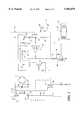
- FIG. 2An embodiment of an amplifier 10 capable of detecting when the headset microphone 16 is disconnected is shown in FIG. 2.
- the amplifier circuit 10includes a transmitter portion 20 and a receiver portion 22. Considering each portion separately, current from the console 12 enters the transmitter portion 20 of the amplifier 10 by way of the central tips 30, 30' of a PJ-327 plug 32.
- a thyristor 36is connected, as a surge protector, across conductors of the central tips 30, 30' of the PS-327 plug 32.
- the signals from the central tips 30, 30' of PJ-327 plug 32are input signals to a bridge 40, that permits a non-polar plug 32 to be used.
- Signals to the receiver portion 22 of the amplifier 10enter the PJ-327 plug 32 from the console 12 by way of the plug sleeves 64, 64'. These signals are coupled by a transformer 66 to the receiver amplifier 68 and then through a second transformer 70 to a speaker 15 of the headset 14.
- DC voltageis supplied by transistor 54 (which supplies power to the transmitter amplifier 60) to the receiver amplifier 68 through a choke 72-capacitor 74 filter combination.
- FIG. 3depicts a similar circuit to that shown in FIG. 2, but which, rather than sensing current through the headset microphone 16, when the headset is plugged into the amplifier 10', senses dc current flow through the headset speaker 15, which flows throught the headset speaker 15 in addition to the audio signal.
- audio signalsare passed by capacitor 80 to speaker 15.
- the current flowresults in current sensing transistor 76 being switched on.
- current sensing transistor 76switches on, the resulting current flowing from the emitter to the collector of current sensing transistor 76, switches on inverter transistor 52.
- the switching on of the inverter transistor 52in turn switches on DC power transistor 54. Again, it is this power drain which is detected by the console 12 and which indicates that the headset 14 is plugged in.
- the circuitry of the amplifier 10"is similar to the circuitry in amplifiers 10 and 10' except that rather than sensing the current flow which bypasses capacitor 42 when microphone 16 is plugged in, the presence of microphone 16 in parallel to ground changes the total resistance of the series of fixed resistors 82, 84, and 86 and gain control potentiometer 46. When the microphone 16 is not plugged in, the total resistance of resistors 82, 84 and 86 and gain control potentiometer 46 results in the biasing of the voltage sensing transistor 90 off, but almost on.
- the voltage drop across gain control potentiometer 46changes (in one embodiment by about 0.3V), switching on voltage sensing transistor 90.
- the switching on of voltage sensing transistor 90switches on inverter transistor 52 and DC power transistor 54, supplying power to the transmitter amplifier 60 and the receiver amplifier 68.
- the voltage sensing transistor 90is again biased barely off, in turn switching off inverter transistor 52 and DC power transistor 54. This results in power being interrupted to both the transmitter amplifier 60 and the receiver amplifier 68 as described previously.
- the console 12is capable of determining whether a microphone 16 is connected to the jack 18 using only the microphone connections presently available and without requiring additional microphone lines be committed for this purpose. Additionally, the use of one of these embodiments of the amplifier of the invention 10, 10', or 10" provides a mean of determining whether an operator is present at a telephone call station without requiring each operator to have an individual amplifier and headset.
Landscapes
- Engineering & Computer Science (AREA)
- Signal Processing (AREA)
- Business, Economics & Management (AREA)
- Marketing (AREA)
- Amplifiers (AREA)
Abstract
Description
Claims (2)
Priority Applications (1)
| Application Number | Priority Date | Filing Date | Title |
|---|---|---|---|
| US07/862,777US5982879A (en) | 1992-04-03 | 1992-04-03 | Telephone headset amplifier and method of operation |
Applications Claiming Priority (1)
| Application Number | Priority Date | Filing Date | Title |
|---|---|---|---|
| US07/862,777US5982879A (en) | 1992-04-03 | 1992-04-03 | Telephone headset amplifier and method of operation |
Publications (1)
| Publication Number | Publication Date |
|---|---|
| US5982879Atrue US5982879A (en) | 1999-11-09 |
Family
ID=25339314
Family Applications (1)
| Application Number | Title | Priority Date | Filing Date |
|---|---|---|---|
| US07/862,777Expired - LifetimeUS5982879A (en) | 1992-04-03 | 1992-04-03 | Telephone headset amplifier and method of operation |
Country Status (1)
| Country | Link |
|---|---|
| US (1) | US5982879A (en) |
Cited By (11)
| Publication number | Priority date | Publication date | Assignee | Title |
|---|---|---|---|---|
| US6249825B1 (en)* | 1997-07-02 | 2001-06-19 | Cypress Semiconductor | Universal serial bus interface system and method |
| US6330325B1 (en)* | 1997-03-31 | 2001-12-11 | Gn Netcom, Inc. | Automatic log-off signaling for telephone systems |
| US20070042762A1 (en)* | 2005-08-19 | 2007-02-22 | Darren Guccione | Mobile conferencing and audio sharing technology |
| US20070260682A1 (en)* | 2006-05-02 | 2007-11-08 | Callpod, Inc. | Wireless communications connection device |
| US20090055569A1 (en)* | 2007-08-24 | 2009-02-26 | Cypress Semiconductor Corporation, A Corporation Of The State Of Delaware | Bridge device with page-access based processor interface |
| US7653123B1 (en) | 2004-09-24 | 2010-01-26 | Cypress Semiconductor Corporation | Dynamic data rate using multiplicative PN-codes |
| US7689724B1 (en) | 2002-08-16 | 2010-03-30 | Cypress Semiconductor Corporation | Apparatus, system and method for sharing data from a device between multiple computers |
| US7765344B2 (en) | 2002-09-27 | 2010-07-27 | Cypress Semiconductor Corporation | Apparatus and method for dynamically providing hub or host operations |
| US8064593B1 (en)* | 2006-01-26 | 2011-11-22 | Plantronics, Inc. | Auto host disconnect on loss of power to a headset amplifier |
| US8090894B1 (en) | 2007-09-21 | 2012-01-03 | Cypress Semiconductor Corporation | Architectures for supporting communication and access between multiple host devices and one or more common functions |
| US8315269B1 (en) | 2007-04-18 | 2012-11-20 | Cypress Semiconductor Corporation | Device, method, and protocol for data transfer between host device and device having storage interface |
Citations (18)
| Publication number | Priority date | Publication date | Assignee | Title |
|---|---|---|---|---|
| US3571518A (en)* | 1968-08-13 | 1971-03-16 | Bell Telephone Labor Inc | Telephone answering system |
| US3851111A (en)* | 1973-09-14 | 1974-11-26 | Gte Automatic Electric Lab Inc | Tsps-headphone plug messages |
| US4048452A (en)* | 1976-05-28 | 1977-09-13 | Bell Telephone Laboratories, Incorporated | Automatic call distribution system |
| US4197430A (en)* | 1978-09-15 | 1980-04-08 | Bell Telephone Laboratories, Incorporated | Operator service position system |
| US4321429A (en)* | 1978-10-20 | 1982-03-23 | Mitsubishi Denki Kabushiki Kaisha | Apparatus for selecting terminal equipment in telephone lines |
| US4400587A (en)* | 1981-08-25 | 1983-08-23 | Rockwell International Corporation | Overflow and diversion to a foreign switch |
| US4406927A (en)* | 1981-05-08 | 1983-09-27 | International Telephone And Telegraph Corporation | Electronic tone ringer |
| US4449017A (en)* | 1982-05-28 | 1984-05-15 | Bell Telephone Laboratories, Incorporated | ACD Combined handset and headset arrangement |
| US4488006A (en)* | 1982-07-01 | 1984-12-11 | At&T Bell Laboratories | Apparatus for controlling the application of telephone line power in a telephone set |
| US4562310A (en)* | 1984-03-29 | 1985-12-31 | Northern Telecom Limited | Keyboard security for a telephone attendant console |
| US4620066A (en)* | 1984-09-27 | 1986-10-28 | At&T Bell Laboratories | Method and apparatus for sharing operators among assistance systems |
| US4672663A (en)* | 1985-06-28 | 1987-06-09 | Mitel Corporation | Telephone handset detector |
| US4682354A (en)* | 1984-12-04 | 1987-07-21 | At&T Company | Automatic call coverage for unattended PBX stations |
| US4951310A (en)* | 1988-05-19 | 1990-08-21 | Fujitsu Limited | Automatic call distribution system |
| US4953207A (en)* | 1988-11-30 | 1990-08-28 | U.S. Philips Corporation | Electronic telephone set |
| US5062103A (en)* | 1988-12-29 | 1991-10-29 | At&T Bell Laboratories | Telephone agent call management system |
| US5073890A (en)* | 1988-12-30 | 1991-12-17 | At&T Bell Laboratories | Remote agent operation for automatic call distributors |
| US5226077A (en)* | 1992-03-02 | 1993-07-06 | Acs Communications, Inc. | Headset amplifier with automatic log on/log off detection |
- 1992
- 1992-04-03USUS07/862,777patent/US5982879A/ennot_activeExpired - Lifetime
Patent Citations (18)
| Publication number | Priority date | Publication date | Assignee | Title |
|---|---|---|---|---|
| US3571518A (en)* | 1968-08-13 | 1971-03-16 | Bell Telephone Labor Inc | Telephone answering system |
| US3851111A (en)* | 1973-09-14 | 1974-11-26 | Gte Automatic Electric Lab Inc | Tsps-headphone plug messages |
| US4048452A (en)* | 1976-05-28 | 1977-09-13 | Bell Telephone Laboratories, Incorporated | Automatic call distribution system |
| US4197430A (en)* | 1978-09-15 | 1980-04-08 | Bell Telephone Laboratories, Incorporated | Operator service position system |
| US4321429A (en)* | 1978-10-20 | 1982-03-23 | Mitsubishi Denki Kabushiki Kaisha | Apparatus for selecting terminal equipment in telephone lines |
| US4406927A (en)* | 1981-05-08 | 1983-09-27 | International Telephone And Telegraph Corporation | Electronic tone ringer |
| US4400587A (en)* | 1981-08-25 | 1983-08-23 | Rockwell International Corporation | Overflow and diversion to a foreign switch |
| US4449017A (en)* | 1982-05-28 | 1984-05-15 | Bell Telephone Laboratories, Incorporated | ACD Combined handset and headset arrangement |
| US4488006A (en)* | 1982-07-01 | 1984-12-11 | At&T Bell Laboratories | Apparatus for controlling the application of telephone line power in a telephone set |
| US4562310A (en)* | 1984-03-29 | 1985-12-31 | Northern Telecom Limited | Keyboard security for a telephone attendant console |
| US4620066A (en)* | 1984-09-27 | 1986-10-28 | At&T Bell Laboratories | Method and apparatus for sharing operators among assistance systems |
| US4682354A (en)* | 1984-12-04 | 1987-07-21 | At&T Company | Automatic call coverage for unattended PBX stations |
| US4672663A (en)* | 1985-06-28 | 1987-06-09 | Mitel Corporation | Telephone handset detector |
| US4951310A (en)* | 1988-05-19 | 1990-08-21 | Fujitsu Limited | Automatic call distribution system |
| US4953207A (en)* | 1988-11-30 | 1990-08-28 | U.S. Philips Corporation | Electronic telephone set |
| US5062103A (en)* | 1988-12-29 | 1991-10-29 | At&T Bell Laboratories | Telephone agent call management system |
| US5073890A (en)* | 1988-12-30 | 1991-12-17 | At&T Bell Laboratories | Remote agent operation for automatic call distributors |
| US5226077A (en)* | 1992-03-02 | 1993-07-06 | Acs Communications, Inc. | Headset amplifier with automatic log on/log off detection |
Cited By (19)
| Publication number | Priority date | Publication date | Assignee | Title |
|---|---|---|---|---|
| US6330325B1 (en)* | 1997-03-31 | 2001-12-11 | Gn Netcom, Inc. | Automatic log-off signaling for telephone systems |
| US6493770B1 (en) | 1997-07-02 | 2002-12-10 | Cypress Semiconductor Corp. | System for reconfiguring a peripheral device by downloading information from a host and electronically simulating a physical disconnection and reconnection to reconfigure the device |
| US6249825B1 (en)* | 1997-07-02 | 2001-06-19 | Cypress Semiconductor | Universal serial bus interface system and method |
| US7689724B1 (en) | 2002-08-16 | 2010-03-30 | Cypress Semiconductor Corporation | Apparatus, system and method for sharing data from a device between multiple computers |
| US7765344B2 (en) | 2002-09-27 | 2010-07-27 | Cypress Semiconductor Corporation | Apparatus and method for dynamically providing hub or host operations |
| US7653123B1 (en) | 2004-09-24 | 2010-01-26 | Cypress Semiconductor Corporation | Dynamic data rate using multiplicative PN-codes |
| US20070042762A1 (en)* | 2005-08-19 | 2007-02-22 | Darren Guccione | Mobile conferencing and audio sharing technology |
| US7899445B2 (en) | 2005-08-19 | 2011-03-01 | Callpod, Inc. | Mobile conferencing and audio sharing technology |
| US7742758B2 (en) | 2005-08-19 | 2010-06-22 | Callpod, Inc. | Mobile conferencing and audio sharing technology |
| US20100227597A1 (en)* | 2005-08-19 | 2010-09-09 | Callpod, Inc. | Mobile conferencing and audio sharing technology |
| US8064593B1 (en)* | 2006-01-26 | 2011-11-22 | Plantronics, Inc. | Auto host disconnect on loss of power to a headset amplifier |
| US20070260682A1 (en)* | 2006-05-02 | 2007-11-08 | Callpod, Inc. | Wireless communications connection device |
| US20100172271A1 (en)* | 2006-05-02 | 2010-07-08 | Callpod, Inc. | Wireless communications connection device |
| US7707250B2 (en) | 2006-05-02 | 2010-04-27 | Callpod, Inc. | Wireless communications connection device |
| US7945624B2 (en) | 2006-05-02 | 2011-05-17 | Callpod, Inc. | Wireless communications connection device |
| US8315269B1 (en) | 2007-04-18 | 2012-11-20 | Cypress Semiconductor Corporation | Device, method, and protocol for data transfer between host device and device having storage interface |
| US8037228B2 (en) | 2007-08-24 | 2011-10-11 | Cypress Semiconductor Corporation | Bridge device with page-access based processor interface |
| US20090055569A1 (en)* | 2007-08-24 | 2009-02-26 | Cypress Semiconductor Corporation, A Corporation Of The State Of Delaware | Bridge device with page-access based processor interface |
| US8090894B1 (en) | 2007-09-21 | 2012-01-03 | Cypress Semiconductor Corporation | Architectures for supporting communication and access between multiple host devices and one or more common functions |
Similar Documents
| Publication | Publication Date | Title |
|---|---|---|
| JP3564127B2 (en) | Automatic logon / logoff detection headphone amplifier | |
| CA2202311C (en) | Self-monitoring line interface circuit | |
| US5982879A (en) | Telephone headset amplifier and method of operation | |
| CA1080869A (en) | Electronic hybrid and hybrid repeater | |
| US5619567A (en) | Variable DC feed characteristic in a subscriber line interface circuit | |
| CA2202312C (en) | Dual voltage, self-monitoring line circuit | |
| KR950015094B1 (en) | Line interface circuit | |
| US4376876A (en) | DC Supply for an electronic signalling device | |
| EP0287369B1 (en) | Remote disconnection and shortcircuiting apparatus | |
| CN1043287C (en) | Protection arrangement for audio output channel | |
| US4330686A (en) | Loudspeaker systems | |
| US4581494A (en) | Telephone interface-test device | |
| US6462923B1 (en) | Coaxial cable protection device | |
| JPH01293748A (en) | Telephone set separation detecting circuit | |
| US4539438A (en) | Active impedance transformer assisted line feed circuit with supervision filtering | |
| US3919487A (en) | Telephone instrument disconnect circuit | |
| US5623544A (en) | Telephone headset interface circuit | |
| US4262172A (en) | Ring-trip detector | |
| EP0906668A1 (en) | Apparatus for automatic sensing of line amplifier configuration for status monitoring | |
| IES20030549A2 (en) | A detecting circuit for detecting the presence of a headset connected to a telephone, and a method for detecting a headset connected to a telephone | |
| US5596568A (en) | Apparatus for protecting a telecommunications network from false alarm conditions due to T1 line signal interruption | |
| EP0199865A1 (en) | Active impedance transformer-assisted line feed circuit with filtering function of supervision signals | |
| JPH0137893B2 (en) | ||
| IE84036B1 (en) | A detecting circuit for detecting the presence of a headset connected to a telephone, and a method for detecting a headset connected to a telephone | |
| CA1240084A (en) | Multi-party line emergency access device |
Legal Events
| Date | Code | Title | Description |
|---|---|---|---|
| AS | Assignment | Owner name:UNEX CORPORATION, MASSACHUSETTS Free format text:ASSIGNMENT OF ASSIGNORS INTEREST.;ASSIGNOR:LUCEY, ROBERT E.;REEL/FRAME:006091/0249 Effective date:19920403 | |
| AS | Assignment | Owner name:GN NETCOM/UNEX INC., MINNESOTA Free format text:ASSIGNMENT OF ASSIGNORS INTEREST;ASSIGNOR:UNEX CORPORATION;REEL/FRAME:008239/0063 Effective date:19961021 | |
| STCF | Information on status: patent grant | Free format text:PATENTED CASE | |
| FEPP | Fee payment procedure | Free format text:PAYOR NUMBER ASSIGNED (ORIGINAL EVENT CODE: ASPN); ENTITY STATUS OF PATENT OWNER: SMALL ENTITY | |
| FPAY | Fee payment | Year of fee payment:4 | |
| FPAY | Fee payment | Year of fee payment:8 | |
| FPAY | Fee payment | Year of fee payment:12 | |
| FEPP | Fee payment procedure | Free format text:PAYER NUMBER DE-ASSIGNED (ORIGINAL EVENT CODE: RMPN); ENTITY STATUS OF PATENT OWNER: SMALL ENTITY Free format text:PAYOR NUMBER ASSIGNED (ORIGINAL EVENT CODE: ASPN); ENTITY STATUS OF PATENT OWNER: SMALL ENTITY | |
| AS | Assignment | Owner name:CALLPOD, INC., ILLINOIS Free format text:ASSIGNMENT OF ASSIGNORS INTEREST;ASSIGNOR:GN NETCOM/UNEX INC.;REEL/FRAME:032411/0950 Effective date:20140312 | |
| FEPP | Fee payment procedure | Free format text:PAT HOLDER CLAIMS SMALL ENTITY STATUS, ENTITY STATUS SET TO SMALL (ORIGINAL EVENT CODE: LTOS); ENTITY STATUS OF PATENT OWNER: SMALL ENTITY | |
| FEPP | Fee payment procedure | Free format text:PAYER NUMBER DE-ASSIGNED (ORIGINAL EVENT CODE: RMPN); ENTITY STATUS OF PATENT OWNER: SMALL ENTITY Free format text:PAYOR NUMBER ASSIGNED (ORIGINAL EVENT CODE: ASPN); ENTITY STATUS OF PATENT OWNER: SMALL ENTITY |