US5982791A - Wavelength tracking in adjustable optical systems - Google Patents
Wavelength tracking in adjustable optical systemsDownload PDFInfo
- Publication number
- US5982791A US5982791AUS09/006,854US685498AUS5982791AUS 5982791 AUS5982791 AUS 5982791AUS 685498 AUS685498 AUS 685498AUS 5982791 AUS5982791 AUS 5982791A
- Authority
- US
- United States
- Prior art keywords
- optical
- carrier
- transfer device
- wavelength
- tracking
- Prior art date
- Legal status (The legal status is an assumption and is not a legal conclusion. Google has not performed a legal analysis and makes no representation as to the accuracy of the status listed.)
- Expired - Lifetime
Links
Images


Classifications
- G—PHYSICS
- G02—OPTICS
- G02B—OPTICAL ELEMENTS, SYSTEMS OR APPARATUS
- G02B6/00—Light guides; Structural details of arrangements comprising light guides and other optical elements, e.g. couplings
- G02B6/24—Coupling light guides
- G02B6/26—Optical coupling means
- G02B6/28—Optical coupling means having data bus means, i.e. plural waveguides interconnected and providing an inherently bidirectional system by mixing and splitting signals
- G02B6/293—Optical coupling means having data bus means, i.e. plural waveguides interconnected and providing an inherently bidirectional system by mixing and splitting signals with wavelength selective means
- G02B6/29304—Optical coupling means having data bus means, i.e. plural waveguides interconnected and providing an inherently bidirectional system by mixing and splitting signals with wavelength selective means operating by diffraction, e.g. grating
- G02B6/29316—Light guides comprising a diffractive element, e.g. grating in or on the light guide such that diffracted light is confined in the light guide
- G02B6/29317—Light guides of the optical fibre type
- G02B6/29322—Diffractive elements of the tunable type
- G—PHYSICS
- G02—OPTICS
- G02B—OPTICAL ELEMENTS, SYSTEMS OR APPARATUS
- G02B6/00—Light guides; Structural details of arrangements comprising light guides and other optical elements, e.g. couplings
- G02B6/02—Optical fibres with cladding with or without a coating
- G02B6/02057—Optical fibres with cladding with or without a coating comprising gratings
- G02B6/02076—Refractive index modulation gratings, e.g. Bragg gratings
- G02B6/02195—Refractive index modulation gratings, e.g. Bragg gratings characterised by means for tuning the grating
- H—ELECTRICITY
- H04—ELECTRIC COMMUNICATION TECHNIQUE
- H04J—MULTIPLEX COMMUNICATION
- H04J14/00—Optical multiplex systems
- H04J14/02—Wavelength-division multiplex systems
- H04J14/0201—Add-and-drop multiplexing
- H04J14/0202—Arrangements therefor
- H04J14/021—Reconfigurable arrangements, e.g. reconfigurable optical add/drop multiplexers [ROADM] or tunable optical add/drop multiplexers [TOADM]
Definitions
- the inventionrelates generally to lightwave communications systems and more specifically to optical systems utilizing fiber Bragg gratings that are responsive to fluctuations in optical carrier wavelength.
- Lightwave networksare increasingly being used to rapidly transfer information around the world.
- Lightwave networksinclude a number of stations, or nodes, that are interconnected by waveguides, typically optical fibers.
- LDlaser diodes
- switchesswitches, amplifiers, multiplexers, and demultiplexers, that are critical to the function of lightwave networks.
- Fiber Bragg gratingsare important building blocks in a variety of lightwave network devices.
- An FBGacts to reflect light energy having a certain wavelength back in the direction from which the light originated.
- FBGscan be used as filters to isolate light energy having a particular wavelength.
- An FBGestablishes a periodic change in refractive index along a core of an optical waveguide, typically an optical fiber. At each period, a portion of the optical wave is reflected, inducing interference in a constructive manner.
- the strength of the change in refractive index along with the grating period and the length of the FBGare factors that determine the range of wavelengths that will be reflected, as well as the efficiency of reflection.
- FBGsfiltering properties and versatility of FBGs have led to the use of FBGs in such devices as wavelength-stabilized lasers, fiber lasers, remotely pumped amplifiers, Raman amplifiers, wavelength converters, passive optical networks, wavelength division multiplexers, demultiplexers, add/drop multiplexers, dispersion compensators, and gain equalizers.
- An add or drop multiplexerallows a specific signal or channel to be added to or dropped from a group of channels. Adding and/or dropping a specific channel is important because optical data is often transmitted in a multiplexed condition, whereby multiple channels of varying wavelengths are sent simultaneously over a single optical fiber.
- a dispersion compensatorcompensates for the time delay that develops when an optical pulse spreads due to its different wavelengths traveling at different speeds.
- FIG. 1An example of a conventional add/drop multiplexer 300 is shown in FIG. 1.
- a first three-port circulator 302is connected to an input fiber 304, a drop fiber 306 and a central fiber 308.
- the central fiberincludes four FBGs 310, 312, 314 and 316 and is connected to a second three-port circulator 318 to function as an input.
- An add fiber 320 and an output fiber 322are also connected to the second circulator 318.
- one of a group of optical carriers that propagate from the input fiber 304 to the central fiber 308is reflected back to the circulator 302 by an appropriately constructed FBG and is directed to the drop fiber 306.
- an optical carrieris introduced to the central fiber from the add fiber 320 via the second circulator 318, but is reflected back to the second circulator for output via the output fiber 322.
- the conventional add/drop moduledoes not have the ability to adjust to fluctuations in optical carrier wavelength.
- the FBGsare manufactured to the predetermined wavelengths of the target optical carriers and no dynamic adjustment is attempted.
- European Pat. No. EPO 0730172 A1 to Chawkialso discloses an optical add/drop multiplexer using optical circulators and a photo-induced Bragg grating.
- the disclosureacts in much the same way as the Huber systems to add and/or drop at least one optical signal with a determined wavelength from a group of signals.
- Each FBGis set to a predetermined wavelength and is able to be tuned in a first state in which the FBG reflects the signal with the predetermined wavelength, thereby transmitting the signals with other wavelengths.
- One or more FBGscan also be set in a second state, in which the adjusted FBGs transmit all of the signals.
- Chawki's add/drop systemhas two circulators and four FBGs, such as the one shown in FIG. 1. Signals are dropped through the left circulator and added through the right circulator.
- the delivery of lightwave data in all of the above-described documentsis similar.
- To deliver lightwave data in an optical networklight is pulsed through a waveguide.
- the lightis typically sent at a known wavelength, and digital data is modulated onto the carrier wavelength.
- the carrier wavelengthknown as the optical carrier, is most effective when the carrier wavelength is fixed throughout transmission. Maintaining a constant carrier wavelength is especially important to devices utilizing FBGs.
- FBGsare wavelength-dependent and are typically fabricated to operate on a particular wavelength or within a narrow bandwidth of wavelengths.
- the conventional sources of lightsuch as laser diodes, are not able to generate a stable optical carrier with the wavelength locked within the tolerances presently desired.
- FBGscan effectively filter out a signal with a bandwidth of 0.2 nm at a single wavelength of 1550 nm. Therefore, if the wavelength of the optical carrier varies outside the bandwidth of the FBG, the filtering efficiency of the FBG is greatly reduced. This is true even for wavelength tunable FBGs that have the ability to effect different optical carrier wavelengths. If the filtering efficiency of an FBG is reduced, the effectiveness of optical devices such as add/drop multiplexers and dispersion compensators declines.
- An unstable optical carriermay allow the optical carrier to inadvertently propagate through a properly tuned FBG. Conversely, an unstable optical carrier may cause the optical carrier to be inadvertently reflected by an FBG.
- What is neededis a method and system that allows the dynamic adjustment of a fiber Bragg grating in response to a varying optical carrier wavelength so that the optical carrier can be effectively manipulated in optical devices such as add/drop modules and dispersion compensators.
- the inventionis a system and method for adjusting a tunable fiber Bragg grating in response to fluctuations in the wavelength of an optical carrier.
- One embodimentinvolves the insertion of a modulated broadband optical signal into a waveguide containing the target FBG, and another embodiment involves modulating a tracking grating and monitoring the optical signal generated by the modulated tracking grating.
- the embodimentscan be used in various optical devices, but are particularly suitable to be applied to add and/or drop modules and dispersion compensators.
- the preferred embodiment of an adjustable system in an add and/or drop moduleincludes a three-port optical circulator, three optical fibers that are selectively coupled by the circulator, a series of tunable FBGs along one of the fibers, a source of a broadband optical noise signal, an optical spectrum analyzer, and an FBG tuner.
- the optical circulatorhas first, second and third ports respectively coupled to first, second and third optical fibers.
- the second fiberreceives an input of optical carriers from the first fiber and is able to output one or more optical carriers to the third fiber, but the fibers are otherwise isolated from one another.
- the tunable FBGsare located along the second fiber and are dynamically tuned in response to detection that transmission characteristics of targeted optical carriers have changed.
- a selected FBGis "roughly” tuned to reflect a targeted optical carrier and is dynamically “fine” tuned to increase the efficiency of back-reflecting the targeted optical carrier.
- the optical spectrum analyzeris utilized to monitor transmission characteristics of a lightwave signal.
- the transmission characteristics of interestare preferably either transmissivity or reflectivity as a function of relative or absolute wavelength.
- an LED or other appropriate broadband light sourcegenerates amplitude modulated probe lightwaves in the same wavelength band as the optical carriers.
- the modulated probe lightwavesare introduced into the first optical fiber at a first coupler.
- the modulated probe lightwavespropagate through the circulator and enter the second optical fiber that includes the dynamically tunable FBGs.
- the modulated probe lightwavesare partially reflected by the FBGs and partially propagate through the FBGs.
- a small portion of the optical energy of the combined signals of the non-reflected modulated probe lightwaves and the non-reflected optical carriersis tapped from the second optical fiber.
- the tapped portion of the combined signalsis directed to the OSA, while the larger portion of the optical energy of the optical carriers is left unaffected by the tracking procedure.
- both the modulated LED-generated lightwaves and the optical carriersare analyzed.
- the OSAseparates the modulated probe lightwaves from the optical carriers using conventional lock-in techniques.
- the condition of one or more of the FBGs with regard to efficiently reflecting one or more targeted optical carriersis determined by measuring optical power at different wavelengths for the modulated probe lightwaves that propagated through the FBGs and comparing them to the center wavelengths of the optical carriers.
- the FBGs in the systemcan be continuously tuned. Tuning the FBGs is executed on an as-needed basis and is implemented by a controller.
- a system as described abovecan be used in optical devices such as add modules, drop modules, add/drop modules or dispersion compensators.
- the important advantage of the inventionis that a fluctuating optical carrier wavelength can be tracked relative to the positions of the FBGs. The tracking information can then be supplied to the controller and the FBGs can be tuned in response to the fluctuation of the optical carrier wavelength. Responsive tuning of FBGs ensures that a target optical carrier is efficiently filtered from a group of optical carriers. Responsive tuning also allows an optical carrier to propagate through optical devices such as add or drop modules with minimum loss when the optical carrier is not intended to be added or dropped.
- Another advantageis that the OSA does not need to be wavelength calibrated, since the OSA compares differences between modulated probe lightwaves and optical carriers, rather than the absolute determination of the wavelengths of individual optical signals.
- optical carrierscan be tracked using an FBG as a tracking grating.
- the tracking FBGis distinguishable from a standard filtering FBG, since the tracking FBG has a narrower bandwidth, has a slightly broader tuning range, and is intentionally less efficient in providing reflection.
- the tracking gratingis also modulated in amplitude or frequency so that the reflected signal can be identified by a receiver.
- the tracking gratingis tuned so that a small portion of the optical energy of the target optical carrier is reflected.
- the target signalis reflected through a circulator and into a receiver located in a third fiber.
- the receivercan monitor the specially modulated signals from the tracking grating and determine the center of the optical carrier channel.
- the associated filtering FBGcan be responsively tuned to efficiently reflect or pass a fluctuating optical carrier.
- the optical systems of the present inventionmay include additional features or alternative embodiments.
- planar glassmay be used as a waveguide in place of the optical fibers.
- FBGsare formed inside the planar glass by treating the glass, such as by selective ionization.
- a series of FBGs having different target wavelengthsare originally formed on the same optical fiber, instead of on different fiber portions that are subsequently spliced together to form a single fiber.
- FBGsare tuned utilizing laser light or RF induction.
- an add and/or drop moduleis disclosed that has a bypass mode.
- FIG. 1is a prior art add/drop system utilizing circulators and FBGs.
- FIG. 2is a depiction of a conventional optical fiber.
- FIG. 3is a depiction of a drop module utilizing LED wavelength tracking in accordance with the present invention.
- FIG. 4is a representation of the power spectrum of modulated LED lightwaves received from a system with six Bragg gratings.
- FIG. 5is a representation of the power spectrum of six optical carriers in a WDM signal.
- FIG. 6is a depiction of an add module utilizing LED wavelength tracking in accordance with the present invention.
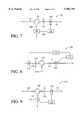
- FIG. 7is a depiction of an alternative embodiment of the present invention.
- FIG. 8is a depiction of an alternative embodiment of the present invention.
- FIG. 9is a depiction of an alternative embodiment of the present invention.
- FIG. 10is a depiction of an alternative embodiment of the present invention.
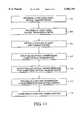
- FIG. 11is a method for tracking an optical carrier in an add and/or drop module in accordance with the present invention.
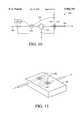
- FIG. 12is planar glass with FBGs in accordance with the present invention.
- FIG. 13is a depiction of a system for tuning an FBG using a laser light in accordance with the present invention.
- FIG. 14is a depiction of a system for tuning an FBG using RF induction in accordance with the present invention.
- FIG. 15is a depiction of a drop module with a bypass mode in accordance with the present invention.
- light pulsesare supplied to an input fiber 12 of a lightwave system, such as a drop multiplexer 20, by a light source (not shown), such as a laser.
- a light sourcesuch as a laser.
- the wavelength (i.e., frequency) of an optical carrier generated by a lasermay fluctuate from the nominal wavelength during its delivery along an optical fiber 12.
- the filtering capability of an FBGcan be greatly reduced and, consequently, the function of an optical device such as an add/drop multiplexer or a dispersion compensator utilizing an FBG is negatively affected.
- the method and system of the present inventionallows the fluctuations in an optical carrier to be continuously tracked in, for example, an add multiplexer, drop multiplexer, an add/drop multiplexer or a dispersion compensator.
- Information gathered from the continuous tracking of the optical carrieris then applied to tuning the appropriate FBG to reflect an optical carrier having the desired wavelength.
- the first element of the preferred drop multiplexeris the waveguide.
- FIG. 2is a depiction of a standard waveguide in the form of an optical fiber 12.
- the optical fiber 12 of FIG. 2has a cylindrical core 14 that is made of doped glass.
- the coreis specially treated to provide the passageway through which lightwaves travel.
- the coreis surrounded by a glass cladding 16.
- the glass claddingaids in directing the lightwaves.
- the glass in the claddinghas a lower refractive index than that of the core. Light propagating along the fiber core is bent at the interface of the core and the cladding toward the core, since the core has the higher refractive index.
- the outer layer of the optical fiberis the coating 18.
- the coating of the optical fiberprotects the core and the cladding from the environment.
- a group of optical fibersis commonly bundled together to create a fiberoptic cable.
- the coatingalso prevents light from the bundled fibers from interfering with one another's signals.
- waveguide in the form of the optical fiber 12has been described, other waveguides may be utilized, such as the waveguide 194 of FIG. 12 or a thermally expanded core (TEC) fiber having an expanded core at its opposite ends.
- TECthermally expanded core
- a drop multiplexer 20 in the preferred embodimentuses a three-port optical circulator 22 as a directional optical transfer device.
- the operation of the circulatorallows optical carriers to pass in only designated directions.
- Optical carriers traveling in the first optical fiber 12are input into the circulator through the first port.
- the optical carrierspropagate through the circulator to the second port and into the second optical fiber 26.
- the second optical fiber 26is considered, for description purposes, to extend from the circulator 22 to the output point 29.
- the circulatorisolates the optical carriers propagating in the second optical fiber from propagating to the first fiber.
- the circulatordirects optical carriers from the second fiber to the third fiber 28, but prevents the reverse exchange of optical carriers.
- An optical couplercan also be used to transfer optical carriers between fibers.
- the optical couplercan be used to add or drop, in conjunction with other devices, a signal from the first fiber 12.
- the optical couplerdoes not have the directional characteristics of the circulator, since it allows signals to travel in both directions. As a result, couplers are often used in conjunction with isolators that permit light to travel in one direction only. Although optical couplers have some different characteristics, they may be used to form alternative embodiments of the present invention.
- an FBGestablishes a periodic change in the refractive index along a core of an optical waveguide.
- the specific design of each FBGdetermines the target wavelength of light that the FBG is able to reflect.
- FIG. 3six FBGs 30, 32, 34, 36, 38 and 40 are depicted in a series. The six FBGs all have different target wavelengths.
- the six FBGs 30-40are wavelength tunable.
- a wavelength tunable FBGis one in which the reflectivity characteristics of the FBG can be changed such that the FBG reflects optical carriers over a range of wavelengths.
- Tuning of an FBGcan be performed in many ways.
- Conventional tuning systems 44include using piezo-electric devices to mechanically tune FBGs or temperature control devices to thermally tune FBGs. Piezo-electric devices place mechanical stress or strain on the FBG to alter the FBG's reflected wavelengths. Varying the temperature of an FBG changes the target wavelength of an FBG in relationship to the FBG's temperature tuning coefficient. Applying resistive heat is a conventional way to tune an FBG.
- An LED 48 in FIG. 3is a conventional LED.
- the LEDgenerates a broadband optical signal.
- the LED used in the preferred embodimentis modulated so that the LED signal can be distinguished from the optical carriers.
- the LEDis shown coupled to the input optical fiber 12, the LED may be coupled in other locations, such as to optical fiber 26.
- a tunable lasercan also provide a similar broadband optical signal.
- An optical spectrum analyzer (OSA) 50can be a basic OSA with minimal calibration capability that is able to monitor various transmission characteristics of a lightwave signal. Measured characteristics of interest in the invention are transmissivity and reflectivity as a function of wavelength. Outputs from the OSA are transmitted through electrical connection 51.
- the LED 48generates modulated probe lightwaves.
- the probe lightwavesare inserted into the first optical fiber 12 at a first weak (1-5%) coupler 52.
- the modulated LED probe lightwavespropagate through the circulator 22 and into the second optical fiber 26.
- the modulated LED probe lightwavesthen travel past the FBGs and a small portion of the combined signals (i.e., 1-5%) of the modulated LED probe lightwaves and the non-reflected optical carriers are tapped from the second optical fiber. Tapping into the second optical fiber is achieved using a second coupler 54.
- the tapped portion of the combined signalis directed to the OSA, while the larger untapped portion continues to conventional transmission or signal processing equipment.
- FIG. 4is a representation of the power spectrum of the modulated probe lightwaves 56 received at the OSA.
- the valleys 58 in the power spectrumrepresent the locations, in terms of wavelength, of the six FBGs 30-40 of FIG. 3. Reflection conditions of the FBGs are identified by the valleys, because the valleys represent positions at which the broadband-modulated probe lightwaves are reflected back by the six FBGs.
- FIG. 5is a representation of the power spectrum of six optical carriers 60 in a wavelength division multiplexed (WDM) signal as measured at the OSA.
- the peaks 62represent optical carriers that are not reflected back by FBGs.
- the series of two small valleys 64represents wavelengths at which optical carriers are reflected back by the FBGs.
- FIGS. 4 and 5can be viewed together to see how the FBG tuning relates to signal transmission.
- an FBGis tuned onto an optical carrier. As a result, the optical carrier does not travel to the OSA, but is instead reflected back.
- position 2an optical carrier is present, but the corresponding FBG is tuned slightly off the frequency of the optical carrier, allowing the optical carrier to pass through to the coupler 54 and, therefore, to the OSA.
- the corresponding FBGsare tuned to the optical carriers and the optical carriers are reflected back.
- the corresponding FBGsare not tuned to the optical carriers and the optical carriers travel to the OSA.
- the optical carrier signalscan be tracked with the OSA using DC detection.
- the results of the trackingcorrespond to FIG. 5.
- the reflection wavelength of the FBGscan also be determined with the OSA by monitoring the modulated LED probe light.
- the FBGscan be continuously tuned as needed by a conventional tuning system 44. Because the system is tuned in response to a comparison of the optical carrier wavelength to the FBG reflection wavelength, calibration of the OSA to determine actual wavelength measurements is not critical.
- an additional OSAcan be used at the third optical fiber 28 of circulator 22.
- a single OSAcan be shared between the second fiber 26 and the third fiber 28 by coupling a monitoring fiber off each of the two fibers 26 and 28 and connecting a switch to the two monitoring fibers. The switch is then changed back and forth to monitor either the second fiber or the third fiber.
- the OSAcan be incorporated into the second fiber 26.
- FIG. 6is a depiction of an add module 70 with wavelength tracking using a modulated LED probe lightwave source 82 and an OSA 80.
- an optical carrieris added through a third optical fiber 72 and a broadband LED probe lightwave signal is inserted through a coupler 90 into a second optical fiber 74 containing the FBGs.
- the LED probe lightwaves, along with a group of optical carriers,travel through the circulator 76 to a first optical fiber 84.
- a sample of the LED lightwaves and the optical carriersis then tapped off at the OSA coupler 78.
- the OSAmonitors the center wavelengths of the optical carriers and the target wavelengths of the FBGs. By comparing the center wavelengths of the optical carriers and the target wavelengths of the FBGs, the controller 88 can tune the FBGs as needed to reflect or pass individual optical carriers.
- add and drop modulesare discussed separately, the two modules can be combined to form an add and drop module with wavelength tracking.
- one LED and one OSAmay be used or more than one LED and more than one OSA may be used.
- an isolatormay be needed between add and drop FBGs to prevent add signals from interfering with the drop portion of the module and to prevent resonant cavities from occurring between the FBGs.
- Dispersion compensators with FBGsutilize the wavelength-dependent time delay created during optical carrier reflection to balance the time dispersion of individual optical pulses in WDM signals. Adjusting the FBGs in response to fluctuations in the wavelengths of the individual optical carriers that make up the WDM signal allows more accurate time delay correction.
- FIG. 7is an alternative embodiment of a drop module 92 that implements a different technique to track the optical carriers.
- the drop modulehas an input optical fiber 91, a circulator 96, and an output optical fiber 97.
- this embodimentutilizes a tracking FBG 94.
- a tracking FBGis different from a standard filtering FBG since the tracking FBG has a narrower bandwidth, has a slightly broader tuning range, and is intentionally less efficient with respect to inducing reflection.
- the tracking grating reflectivityis also modulated in amplitude or frequency, so that the reflected signal can be identified by a receiver.
- the technique of modulatingis also referred to as "dithering." Although only one tracking grating and one filter grating are shown for discussion purposes, additional filter gratings and tracking gratings can be added to handle a wider range of signals.
- the dithered tracking gratingis progressively swept across the entire bandwidth of the optical carrier signal. Progressively tuning the tracking grating across the entire bandwidth of the optical carrier causes a small percentage of the optical carrier to be reflected over the entire bandwidth of the optical carrier.
- the target signalis reflected in a modulated form through the circulator 96 and into a receiver 98 located along a third optical fiber 100.
- the receivermonitors the specially modulated signal from the tracking grating 94.
- the optical carrier signal centeris determined from the monitored signal that is created from the dithered signal.
- the reflective wavelength of the filtering FBGcan be determined in a controller 104 by accessing a wavelength versus temperature or wavelength versus strain look-up table.
- the reflective wavelength of the filtering FBGcan be determined by knowing the wavelength versus temperature or wavelength versus strain relationship for the tracking FBG 94 and using the commonality between the filtering FBG and the tracking FBG to determine the reflective wavelength of the filtering FBG.
- the controller 104is used to execute the dynamic tuning of the filtering FBG 102.
- the controllerchanges the temperature of the FBG by changing the current through, for example, a thermoelectric cooler.
- the temperature changeis monitored by a thermistor.
- FIG. 8is an alternative embodiment of an add module 106 utilizing the tracking grating technique for tracking a fluctuating optical carrier.
- an optical carrieris directed to a circulator 107 through a third fiber 108.
- the circulatortransfers the optical carrier to a second fiber 110 having FBGs 112 and 114.
- the first FBGis a tracking grating 112 and the second FBG is a filter grating 114.
- the tracking gratingis tuned to reflect a small sample of the target optical carrier.
- the reflected portiontravels through a first fiber 116 and a small sample is tapped off through a coupler 120 into a receiver 118.
- the receiverinterprets the dithered tracking signal, and a grating controller 122 can then tune the filter FBG in response to information from the receiver.
- the tracking gratingcan continuously track an optical carrier at time intervals that allow a tuning grating to fluctuate in unison with fluctuations in the optical carrier.
- FIG. 9is a depiction of an alternative embodiment of a drop module 124 with an optical carrier wavelength tracking system using a tracking grating.
- the embodimentincludes three optical fibers connected to a circulator 138.
- a second fiber 126has a modulated tracking grating 128 and a filter grating 130, where both gratings are tunable FBGs.
- optical carriersare input through the first fiber 140 and into the second fiber.
- the tracking grating in the second fiberreflects a small portion of the target optical carrier back to the circulator 138 and into the third fiber 134.
- a small sample (typically 1-5%) of the optical carrier signalis tapped off and sent to the receiver/controller 136.
- the receiver/controller 136processes the signal and determines the center wavelength of the optical carrier. With the center wavelength of the optical carrier known, the controller can tune the filter FBG.
- the filter FBGis typically tuned to either completely reflect the optical carrier or to completely pass the optical carrier.
- FIG. 10is a depiction of another alternative embodiment of a drop module 142 with an optical wavelength tracking system.
- the embodimentincludes three optical fibers connected to a three-port circulator 144.
- a second fiber 146contains a filter grating 148.
- a tracking fiber 150 and a tracking grating 156are coupled to the first fiber 152.
- the coupler 154 on the first fibertaps off a small sample of the optical carrier signal.
- the optical carrieris reflected back along the tracking fiber by the tracking grating.
- a receiver/controller 158is connected to the tracking fiber.
- the receiverprocesses the signal and determines the center wavelength of the optical carrier. With the center wavelength of the optical carrier known, the controller can tune the filter FBG. Since the tracking fiber is separate from the main optical carrier signal, the tracking grating does not have to be specially modulated to be identified by a receiver.
- FIG. 11depicts a method of transmitting an optical carrier.
- the first step 162 in the methodis to provide a first directional optical transfer device having at least three optical ports for the input and output of a group of optical carriers.
- the next step 164is to provide at least three optical transmission paths, with the three optical transmission paths respectively connected to the three optical ports of the directional optical transfer device.
- the next step 166is optically coupling at least one tunable grating to one of the optical transmission paths.
- the tunable gratinghas the ability to reflect a selected optical wavelength.
- the next step 168is to input an optical carrier along a first optical transmission path and into the first directional optical transfer device.
- the first optical transmission pathis one of the three previously identified optical transmission paths.
- the next step 170is to output the optical carrier from the first directional optical transfer device along a second optical transmission path, where the second optical transmission path is optically coupled to at least one tunable grating.
- the next step 172is to track at least one transmission characteristic of the optical carrier.
- the last step 174is to dynamically tune the tunable grating in response to data gathered from the tracking of the transmission characteristic of the optical carrier. The grating is tuned such that the optical carrier is reflected back and dropped from a group of optical carriers, added to a group of optical carriers, or the time-shape of the pulses on the optical carrier is adjusted to compensate for wavelength dispersion.
- cladding lossis caused when light reflected by FBGs couples from the core of an optical fiber into the cladding of the fiber. The light in the cladding then couples back into the core and interferes with the original light traveling in the core.
- absorbent ringsare formed in the cladding of the fiber. The absorbent rings are formed by adding dopants to the cladding. The dopants in the cladding prevent light from traveling from the cladding back into the fiber.
- a "waveguide”is defined herein as any structure that establishes a transmission path for lightwave information transmissions.
- optical fibersare the preferred waveguides, there are other waveguides that may be used in lightwave add and/or drop modules of the type described above.
- planar glassReferring to FIG. 12, planar glass 194 can be used to direct lightwaves by providing a pattern of ionization that defines a transmission path 197 by changing the refractive index of the glass along the transmission path.
- Gratings 196can be formed inside the planar glass. The gratings are formed internally in the glass structure and have similar characteristics to gratings in optical fibers.
- FBGs that are formed in optical fibersare conventionally manufactured in a process in which multiple FBGs having the same target wavelength are formed on a single optical fiber.
- the single optical fiberis then diced into individual FBG fiber segments.
- FBGs that have different target wavelengthscan be formed on a single fiber. Having the FBGs formed on a single fiber can reduce the transmission losses created by splicing FBGs together onto one single fiber.
- Conventional methods for tuning FBGsinclude piezo-electric compression and thermal resistive heating. Both of these conventional methods can be applied to the embodiments of the present invention. In addition to the conventional methods, alternative methods can be applied. Two alternative tuning methods include utilizing laser light and RF induction.
- FIG. 13shows an optical fiber 198 with an FBG 200 formed inside the optical fiber.
- the optical fiberhas an annular thermally conductive material 202 that is placed around the optical fiber at the point where the FBG is located.
- Laser light 204is then systematically applied to the area of the fiber that contains the grating.
- the laser lightgenerates heat on impact with the thermally conductive material.
- the intensity of laser light applied to the area of the fiber that contains the gratingdirectly affects the temperature of the grating, which in turn manipulates the target wavelength of the grating.
- Laser lightcan be applied with high accuracy and the laser light doses can be calibrated to provide responsive temperature control.
- FIG. 14shows the outside of an optical fiber 206 with an FBG formed inside the fiber.
- An annular band 208 of thermally conductive materialis placed around the coating of the fiber at the location of the FBG.
- a conductive wire 210is then coiled around the band of the conductive material. Voltage is applied to the conductive wire and RF induction generates thermal energy by virtue of I 2 R losses along the thermally conductive band, thereby tuning the FBGs.
- FIG. 15represents a drop module with bypass capability.
- the systemhas an input fiber 212, a drop fiber 214, a bypass fiber 216, a grating fiber 218, an output fiber 220, a series of FBGs 222, and a switch 224.
- an optical carrieris propagated through the input fiber.
- the switchis contacted with the grating fiber 218, the optical carriers travel through the grating fiber and are either propagated to the output fiber 220 or are reflected back through the drop fiber 214 by a particular grating.
- the switchis in contact with the bypass fiber, the optical carriers travel through the bypass fiber directly to the output fiber.
- the bypass embodimentallows a group of FBGs to be completely bypassed if a problem occurs in an FBG or if the FBGs need to be serviced or replaced.
- the bypass mode embodimentcan be applied to an add module as well as to a drop module.
Landscapes
- Physics & Mathematics (AREA)
- General Physics & Mathematics (AREA)
- Optics & Photonics (AREA)
- Engineering & Computer Science (AREA)
- Computer Networks & Wireless Communication (AREA)
- Signal Processing (AREA)
- Optical Communication System (AREA)
- Mechanical Light Control Or Optical Switches (AREA)
Abstract
Description
Claims (18)
Priority Applications (4)
| Application Number | Priority Date | Filing Date | Title |
|---|---|---|---|
| US09/006,854US5982791A (en) | 1998-01-14 | 1998-01-14 | Wavelength tracking in adjustable optical systems |
| DE69826104TDE69826104T2 (en) | 1998-01-14 | 1998-10-02 | Frequency tracking in tunable optical systems |
| EP98118663AEP0930741B1 (en) | 1998-01-14 | 1998-10-02 | Wavelength tracking in adjustable optical systems |
| JP11008374AJPH11264943A (en) | 1998-01-14 | 1999-01-14 | Wavelength tracking in adjustable optical system |
Applications Claiming Priority (1)
| Application Number | Priority Date | Filing Date | Title |
|---|---|---|---|
| US09/006,854US5982791A (en) | 1998-01-14 | 1998-01-14 | Wavelength tracking in adjustable optical systems |
Publications (1)
| Publication Number | Publication Date |
|---|---|
| US5982791Atrue US5982791A (en) | 1999-11-09 |
Family
ID=21722947
Family Applications (1)
| Application Number | Title | Priority Date | Filing Date |
|---|---|---|---|
| US09/006,854Expired - LifetimeUS5982791A (en) | 1998-01-14 | 1998-01-14 | Wavelength tracking in adjustable optical systems |
Country Status (4)
| Country | Link |
|---|---|
| US (1) | US5982791A (en) |
| EP (1) | EP0930741B1 (en) |
| JP (1) | JPH11264943A (en) |
| DE (1) | DE69826104T2 (en) |
Cited By (63)
| Publication number | Priority date | Publication date | Assignee | Title |
|---|---|---|---|---|
| US20010030786A1 (en)* | 2000-04-12 | 2001-10-18 | Sumitomo Electric Industries, Ltd. | Optical add/drop multiplexer apparatus, method of controlling the same and optical communication system |
| US6389200B1 (en) | 1999-12-28 | 2002-05-14 | Alcatel Usa Sourcing, L.P. | Wide tuning range fiber bragg grating filter (FBGF) using muscle wire |
| US6411748B1 (en) | 2000-07-17 | 2002-06-25 | Alcatel Usa Sourcing, L.P. | Wide tuning range acousto-optical fiber Bragg grating filter (FBGF) |
| US6426496B1 (en)* | 2000-08-22 | 2002-07-30 | The United States Of America As Represented By The Administrator Of The National Aeronautics And Space Administration | High precision wavelength monitor for tunable laser systems |
| US20020126714A1 (en)* | 2001-02-07 | 2002-09-12 | Hong Po | Raman fiber laser |
| KR20020077569A (en)* | 2001-04-02 | 2002-10-12 | 전자부품연구원 | Optical add drop multiplexer using light fiber grating |
| US6480513B1 (en) | 2000-10-03 | 2002-11-12 | K2 Optronics, Inc. | Tunable external cavity laser |
| US6486466B1 (en)* | 1999-04-28 | 2002-11-26 | Tyco Telecommunications (Us) Inc. | Wide bandwidth raman amplifier having a substantially flat gain profile |
| US6492636B1 (en)* | 1997-08-19 | 2002-12-10 | The University Of Maryland | Large scale high speed multiplexed optical fiber sensor network |
| US6501874B1 (en)* | 2001-09-25 | 2002-12-31 | Inplane Photonics, Inc. | Dispersion compensator using Bragg gratings in transmission |
| US20030016911A1 (en)* | 2001-07-19 | 2003-01-23 | Samad Talebpour | Random access optical add/drop switch |
| US6525849B1 (en)* | 2000-01-28 | 2003-02-25 | National Science Council | Probe of two-way optical component network analyzer |
| US6570894B2 (en) | 2001-01-30 | 2003-05-27 | Tektronix, Inc. | Real-time wavelength calibration for swept lasers |
| US6597481B1 (en)* | 1999-02-19 | 2003-07-22 | Lucent Technologies Inc. | Controllable wavelength-selective optical cross-connect |
| US20030138000A1 (en)* | 2002-01-11 | 2003-07-24 | Alcatel | Cascaded Raman fiber laser, and optical system including such a laser |
| US6614569B2 (en) | 2001-02-12 | 2003-09-02 | Sycamore Networks, Inc. | System and method for narrow channel spaced dense wavelength division multiplexing/demultiplexing |
| US20030184848A1 (en)* | 2002-03-27 | 2003-10-02 | Alcatel | Raman fiber amplification stage, optical system and method to control the Raman amplification |
| US20030223752A1 (en)* | 2002-06-04 | 2003-12-04 | Ximin Zhao | Dynamic power optical splitter |
| US20030223687A1 (en)* | 2002-05-30 | 2003-12-04 | Robert Blomquist | Closed-loop control of tunable optical wavelength filters |
| US6684005B1 (en)* | 1999-09-27 | 2004-01-27 | Cisco Systems (Sweden) Aktiebolag | Connection of an add/drop node |
| US6704512B1 (en)* | 1998-12-10 | 2004-03-09 | Lg Information & Communications, Ltd. | WDM optical channel dispersion compensating and monitoring apparatus and optical amplifier comprising the apparatus |
| US20040046109A1 (en)* | 2002-09-05 | 2004-03-11 | Chen Peter C. | Method and apparatus for high speed interrogation of fiber optic detector arrays |
| US6738543B1 (en)* | 2002-05-30 | 2004-05-18 | E. I. Du Pont De Nemours And Company | Hitless tunable wavelength filters |
| US20040109638A1 (en)* | 2002-09-20 | 2004-06-10 | Sumitomo Electric Industries, Ltd. | Gain equalizer and optical amplification apparatus |
| US20040114863A1 (en)* | 2002-12-17 | 2004-06-17 | Eggleton Benjamin J. | Colorless tunable dispersion compensator |
| US6788900B1 (en)* | 1999-02-09 | 2004-09-07 | Marconi Communications Limited | System for checking the operation of an optical filter |
| US20040179797A1 (en)* | 2001-07-02 | 2004-09-16 | Hong Po | Multi-wavelength optical fiber |
| US20040208580A1 (en)* | 2002-07-05 | 2004-10-21 | Ximin Zhao | Re-configurable optical add-drop multiplexer |
| US20040240043A1 (en)* | 2001-08-03 | 2004-12-02 | Demidov Andrey A. | Optical fiber amplifier |
| US20040264834A1 (en)* | 2003-06-26 | 2004-12-30 | Mcintyre Thomas J. | Feedback controlled photonic frequency selection circuit |
| US6898348B2 (en)* | 2000-12-04 | 2005-05-24 | Jds Uniphase Corporation | Spectral power equalizer for wavelength-multiplexed optical fiber communication links |
| US20060127004A1 (en)* | 2004-12-13 | 2006-06-15 | General Dynamics Advanced Information Systems, Inc. | System and method for performing dispersion compensation |
| US20060182392A1 (en)* | 2005-02-16 | 2006-08-17 | Universite Laval | Device for tailoring the chromatic dispersion of a light signal |
| US7127169B1 (en)* | 2002-08-05 | 2006-10-24 | Alliance Fiber Optic Products, Inc. | Fiber optic tunable add-drop multiplexer/demultiplexer |
| US20060285794A1 (en)* | 2005-06-21 | 2006-12-21 | Meyer A D | Multi-wavelength optical source |
| US7277610B2 (en) | 2001-05-15 | 2007-10-02 | Nufern | Optical fiber and system containing same |
| US20070264012A1 (en)* | 2004-09-30 | 2007-11-15 | Peter Healey | Identifying or Locating Waveguides |
| US20080123085A1 (en)* | 2004-12-17 | 2008-05-29 | Sikora Edmund Sr | Assessing A Network |
| US20080219660A1 (en)* | 2005-03-31 | 2008-09-11 | Peter Healey | Communicating Information |
| US20090251766A1 (en)* | 2005-11-04 | 2009-10-08 | Hiroyuki Furuya | Wavelength converter |
| US20100221010A1 (en)* | 2009-02-27 | 2010-09-02 | Oki Electric Industry Co., Ltd. | Encoding-decoding method, optical pulse time spreading apparatus, optical add-drop-multiplexer, and optical communication system |
| US7796896B2 (en) | 2003-09-30 | 2010-09-14 | British Telecommunications Plc | Secure optical communication |
| US7817279B2 (en) | 2006-02-24 | 2010-10-19 | British Telecommunications Public Limited Company | Sensing a disturbance |
| US7961331B2 (en) | 2006-02-24 | 2011-06-14 | British Telecommunications Public Limited Company | Sensing a disturbance along an optical path |
| US7974182B2 (en)* | 2004-03-31 | 2011-07-05 | British Telecommunications Public Limited Company | Evaluating the position of a disturbance |
| US7995197B2 (en) | 2004-09-30 | 2011-08-09 | British Telecommunications Public Limited Company | Distributed backscattering |
| US8000609B2 (en) | 2005-04-14 | 2011-08-16 | British Telecommunications Public Limited Company | Communicating or reproducing an audible sound |
| US8003932B2 (en) | 2005-06-02 | 2011-08-23 | British Telecommunications Public Limited Company | Evaluating the position of a disturbance |
| US20110224686A1 (en)* | 2005-12-30 | 2011-09-15 | Intuitive Surgical Operations, Inc. | Robotic surgery system including position sensors using fiber bragg gratings |
| US8027584B2 (en) | 2006-02-24 | 2011-09-27 | British Telecommunications Public Limited Company | Sensing a disturbance |
| US20110249979A1 (en)* | 2010-04-09 | 2011-10-13 | Lan Sheng | Tunable dispersion compensator configured for continuous setpoint control |
| US8670662B2 (en) | 2006-04-03 | 2014-03-11 | British Telecommunications Public Limited Company | Evaluating the position of an optical fiber disturbance |
| US9060678B2 (en) | 2006-06-13 | 2015-06-23 | Intuitive Surgical Operations, Inc. | Minimally invasive surgical system |
| US9387048B2 (en) | 2011-10-14 | 2016-07-12 | Intuitive Surgical Operations, Inc. | Catheter sensor systems |
| US9452276B2 (en) | 2011-10-14 | 2016-09-27 | Intuitive Surgical Operations, Inc. | Catheter with removable vision probe |
| CN106602394A (en)* | 2017-01-19 | 2017-04-26 | 吉林大学 | Resonant cavity system formed by dynamic fiber grating and fiber bragg grating |
| US9757149B2 (en) | 2006-06-13 | 2017-09-12 | Intuitive Surgical Operations, Inc. | Surgical system entry guide |
| US9962066B2 (en) | 2005-12-30 | 2018-05-08 | Intuitive Surgical Operations, Inc. | Methods and apparatus to shape flexible entry guides for minimally invasive surgery |
| US10238837B2 (en) | 2011-10-14 | 2019-03-26 | Intuitive Surgical Operations, Inc. | Catheters with control modes for interchangeable probes |
| US10682070B2 (en) | 2011-10-14 | 2020-06-16 | Intuitive Surgical Operations, Inc. | Electromagnetic sensor with probe and guide sensing elements |
| EP3859913A1 (en) | 2020-01-30 | 2021-08-04 | Thorlabs Quantum Electronics, Inc. | Tunable laser assembly |
| EP3879643A1 (en) | 2020-03-09 | 2021-09-15 | Thorlabs Quantum Electronics, Inc. | Tunable laser assembly and method of control |
| CN114731201A (en)* | 2019-11-07 | 2022-07-08 | 米兰综合工科大学 | Optical system including reconfigurable device and optical system control method |
Families Citing this family (8)
| Publication number | Priority date | Publication date | Assignee | Title |
|---|---|---|---|---|
| FI990238A7 (en) | 1999-02-08 | 2000-08-09 | Nokia Networks Oy | OpticalADd/drop device |
| CA2324709A1 (en)* | 1999-11-05 | 2001-05-05 | Jds Uniphase Inc. | Tunable dispersion compensator |
| US6519065B1 (en) | 1999-11-05 | 2003-02-11 | Jds Fitel Inc. | Chromatic dispersion compensation device |
| NO313606B1 (en)* | 1999-11-09 | 2002-10-28 | Optoplan As | Wavelength controlled FBG filter |
| KR20010057443A (en)* | 1999-12-23 | 2001-07-04 | 이계철 | Device of optical wavelength locking |
| EP1134608A1 (en)* | 2000-03-14 | 2001-09-19 | Lucent Technologies Inc. | Drop node having an optical drop and continue function for an optical transmission network |
| EP1253687B1 (en) | 2001-10-06 | 2003-07-23 | Agilent Technologies, Inc. (a Delaware corporation) | Self-adjustable tunable filter |
| US10209060B1 (en)* | 2014-07-31 | 2019-02-19 | iSenseCloud, Inc. | Fiber-optic sensors in a rosette or rosette-like pattern for structure monitoring |
Citations (6)
| Publication number | Priority date | Publication date | Assignee | Title |
|---|---|---|---|---|
| US5418802A (en)* | 1993-11-12 | 1995-05-23 | Eastman Kodak Company | Frequency tunable waveguide extended cavity laser |
| US5469520A (en)* | 1994-09-30 | 1995-11-21 | United Technologies Corporation | Compression-tuned fiber grating |
| US5511086A (en)* | 1995-03-22 | 1996-04-23 | The Texas A&M University System | Low noise and narrow linewidth external cavity semiconductor laser for coherent frequency and time domain reflectometry |
| EP0730172A1 (en)* | 1995-02-28 | 1996-09-04 | France Telecom | Add-drop optical multiplexer comprising optical circulators and photoinscripted Bragg-gratings |
| US5555118A (en)* | 1993-06-04 | 1996-09-10 | Ciena Corporation | Method for removing and inserting optical carriers in a WDM optical communication system |
| US5600473A (en)* | 1993-06-04 | 1997-02-04 | Ciena Corporation | Optical amplifier systems with add/drop multiplexing |
Family Cites Families (1)
| Publication number | Priority date | Publication date | Assignee | Title |
|---|---|---|---|---|
| JP3256713B2 (en)* | 1992-06-27 | 2002-02-12 | キヤノン株式会社 | Wavelength tunable filter control method, control device, and optical communication system using the same |
- 1998
- 1998-01-14USUS09/006,854patent/US5982791A/ennot_activeExpired - Lifetime
- 1998-10-02DEDE69826104Tpatent/DE69826104T2/ennot_activeExpired - Fee Related
- 1998-10-02EPEP98118663Apatent/EP0930741B1/ennot_activeExpired - Lifetime
- 1999
- 1999-01-14JPJP11008374Apatent/JPH11264943A/ennot_activeWithdrawn
Patent Citations (7)
| Publication number | Priority date | Publication date | Assignee | Title |
|---|---|---|---|---|
| US5555118A (en)* | 1993-06-04 | 1996-09-10 | Ciena Corporation | Method for removing and inserting optical carriers in a WDM optical communication system |
| US5579143A (en)* | 1993-06-04 | 1996-11-26 | Ciena Corporation | Optical system with tunable in-fiber gratings |
| US5600473A (en)* | 1993-06-04 | 1997-02-04 | Ciena Corporation | Optical amplifier systems with add/drop multiplexing |
| US5418802A (en)* | 1993-11-12 | 1995-05-23 | Eastman Kodak Company | Frequency tunable waveguide extended cavity laser |
| US5469520A (en)* | 1994-09-30 | 1995-11-21 | United Technologies Corporation | Compression-tuned fiber grating |
| EP0730172A1 (en)* | 1995-02-28 | 1996-09-04 | France Telecom | Add-drop optical multiplexer comprising optical circulators and photoinscripted Bragg-gratings |
| US5511086A (en)* | 1995-03-22 | 1996-04-23 | The Texas A&M University System | Low noise and narrow linewidth external cavity semiconductor laser for coherent frequency and time domain reflectometry |
Non-Patent Citations (2)
| Title |
|---|
| Giles, C.R., "Lightwave Applications of Fiber Bragg Gratings," Journal of Lightwave Technology, vol. 15, No. 8, Aug. 1997, pp. 1391-1404. |
| Giles, C.R., Lightwave Applications of Fiber Bragg Gratings, Journal of Lightwave Technology , vol. 15, No. 8, Aug. 1997, pp. 1391 1404.* |
Cited By (123)
| Publication number | Priority date | Publication date | Assignee | Title |
|---|---|---|---|---|
| US6492636B1 (en)* | 1997-08-19 | 2002-12-10 | The University Of Maryland | Large scale high speed multiplexed optical fiber sensor network |
| US6704512B1 (en)* | 1998-12-10 | 2004-03-09 | Lg Information & Communications, Ltd. | WDM optical channel dispersion compensating and monitoring apparatus and optical amplifier comprising the apparatus |
| US6788900B1 (en)* | 1999-02-09 | 2004-09-07 | Marconi Communications Limited | System for checking the operation of an optical filter |
| US6597481B1 (en)* | 1999-02-19 | 2003-07-22 | Lucent Technologies Inc. | Controllable wavelength-selective optical cross-connect |
| US6486466B1 (en)* | 1999-04-28 | 2002-11-26 | Tyco Telecommunications (Us) Inc. | Wide bandwidth raman amplifier having a substantially flat gain profile |
| US6684005B1 (en)* | 1999-09-27 | 2004-01-27 | Cisco Systems (Sweden) Aktiebolag | Connection of an add/drop node |
| US6999654B1 (en) | 1999-09-27 | 2006-02-14 | Cisco Technology, Inc. | Connection of on an add/drop node |
| US20060018593A1 (en)* | 1999-09-27 | 2006-01-26 | Lars Egnell | Connection of an add/drop node |
| US6389200B1 (en) | 1999-12-28 | 2002-05-14 | Alcatel Usa Sourcing, L.P. | Wide tuning range fiber bragg grating filter (FBGF) using muscle wire |
| US6525849B1 (en)* | 2000-01-28 | 2003-02-25 | National Science Council | Probe of two-way optical component network analyzer |
| US20010030786A1 (en)* | 2000-04-12 | 2001-10-18 | Sumitomo Electric Industries, Ltd. | Optical add/drop multiplexer apparatus, method of controlling the same and optical communication system |
| US6411748B1 (en) | 2000-07-17 | 2002-06-25 | Alcatel Usa Sourcing, L.P. | Wide tuning range acousto-optical fiber Bragg grating filter (FBGF) |
| US6426496B1 (en)* | 2000-08-22 | 2002-07-30 | The United States Of America As Represented By The Administrator Of The National Aeronautics And Space Administration | High precision wavelength monitor for tunable laser systems |
| US6480513B1 (en) | 2000-10-03 | 2002-11-12 | K2 Optronics, Inc. | Tunable external cavity laser |
| US6898348B2 (en)* | 2000-12-04 | 2005-05-24 | Jds Uniphase Corporation | Spectral power equalizer for wavelength-multiplexed optical fiber communication links |
| US6570894B2 (en) | 2001-01-30 | 2003-05-27 | Tektronix, Inc. | Real-time wavelength calibration for swept lasers |
| US20020126714A1 (en)* | 2001-02-07 | 2002-09-12 | Hong Po | Raman fiber laser |
| US6959021B2 (en)* | 2001-02-07 | 2005-10-25 | Ocg Technology Licensing, Llc | Raman fiber laser |
| US6614569B2 (en) | 2001-02-12 | 2003-09-02 | Sycamore Networks, Inc. | System and method for narrow channel spaced dense wavelength division multiplexing/demultiplexing |
| KR20020077569A (en)* | 2001-04-02 | 2002-10-12 | 전자부품연구원 | Optical add drop multiplexer using light fiber grating |
| US7277610B2 (en) | 2001-05-15 | 2007-10-02 | Nufern | Optical fiber and system containing same |
| US20040179797A1 (en)* | 2001-07-02 | 2004-09-16 | Hong Po | Multi-wavelength optical fiber |
| US7340136B2 (en)* | 2001-07-02 | 2008-03-04 | Ocg Technology Licensing, Llc | Multi-wavelength optical fiber |
| US20030016911A1 (en)* | 2001-07-19 | 2003-01-23 | Samad Talebpour | Random access optical add/drop switch |
| US7463411B2 (en) | 2001-08-03 | 2008-12-09 | Demidov Andrey A | Optical fiber amplifier |
| US20040240043A1 (en)* | 2001-08-03 | 2004-12-02 | Demidov Andrey A. | Optical fiber amplifier |
| US6501874B1 (en)* | 2001-09-25 | 2002-12-31 | Inplane Photonics, Inc. | Dispersion compensator using Bragg gratings in transmission |
| US6836488B2 (en)* | 2002-01-11 | 2004-12-28 | Alcatel | Cascaded Raman fiber laser, and optical system including such a laser |
| US20030138000A1 (en)* | 2002-01-11 | 2003-07-24 | Alcatel | Cascaded Raman fiber laser, and optical system including such a laser |
| US20030184848A1 (en)* | 2002-03-27 | 2003-10-02 | Alcatel | Raman fiber amplification stage, optical system and method to control the Raman amplification |
| US20030223687A1 (en)* | 2002-05-30 | 2003-12-04 | Robert Blomquist | Closed-loop control of tunable optical wavelength filters |
| US6738543B1 (en)* | 2002-05-30 | 2004-05-18 | E. I. Du Pont De Nemours And Company | Hitless tunable wavelength filters |
| US6728445B2 (en) | 2002-05-30 | 2004-04-27 | E. I. Du Ponte De Nemours And Company | Closed-loop control of tunable optical wavelength filters |
| US20030223752A1 (en)* | 2002-06-04 | 2003-12-04 | Ximin Zhao | Dynamic power optical splitter |
| US7068939B2 (en)* | 2002-06-04 | 2006-06-27 | Hon Hai Precision Ind. Co., Ltd. | Dynamic power optical splitter |
| US20040208580A1 (en)* | 2002-07-05 | 2004-10-21 | Ximin Zhao | Re-configurable optical add-drop multiplexer |
| US7136589B2 (en)* | 2002-07-05 | 2006-11-14 | Hon Hai Precision Ind. Co., Ltd | Re-configurable optical add-drop multiplexer |
| US7127169B1 (en)* | 2002-08-05 | 2006-10-24 | Alliance Fiber Optic Products, Inc. | Fiber optic tunable add-drop multiplexer/demultiplexer |
| US20040046109A1 (en)* | 2002-09-05 | 2004-03-11 | Chen Peter C. | Method and apparatus for high speed interrogation of fiber optic detector arrays |
| US6952511B2 (en)* | 2002-09-20 | 2005-10-04 | Sumitomo Electric Industries, Ltd. | Gain equalizer and optical amplification apparatus |
| US20040109638A1 (en)* | 2002-09-20 | 2004-06-10 | Sumitomo Electric Industries, Ltd. | Gain equalizer and optical amplification apparatus |
| US6847763B2 (en)* | 2002-12-17 | 2005-01-25 | Fitel U.S.A. Corp | Colorless tunable dispersion compensator |
| US20040114863A1 (en)* | 2002-12-17 | 2004-06-17 | Eggleton Benjamin J. | Colorless tunable dispersion compensator |
| US20040264834A1 (en)* | 2003-06-26 | 2004-12-30 | Mcintyre Thomas J. | Feedback controlled photonic frequency selection circuit |
| US7796896B2 (en) | 2003-09-30 | 2010-09-14 | British Telecommunications Plc | Secure optical communication |
| US7974182B2 (en)* | 2004-03-31 | 2011-07-05 | British Telecommunications Public Limited Company | Evaluating the position of a disturbance |
| US7995197B2 (en) | 2004-09-30 | 2011-08-09 | British Telecommunications Public Limited Company | Distributed backscattering |
| US20070264012A1 (en)* | 2004-09-30 | 2007-11-15 | Peter Healey | Identifying or Locating Waveguides |
| US7848645B2 (en) | 2004-09-30 | 2010-12-07 | British Telecommunications Public Limited Company | Identifying or locating waveguides |
| US7295738B2 (en)* | 2004-12-13 | 2007-11-13 | General Dynamics Advanced Information Systems, Inc. | System and method for performing dispersion compensation |
| US20060127004A1 (en)* | 2004-12-13 | 2006-06-15 | General Dynamics Advanced Information Systems, Inc. | System and method for performing dispersion compensation |
| US20080123085A1 (en)* | 2004-12-17 | 2008-05-29 | Sikora Edmund Sr | Assessing A Network |
| US8045174B2 (en) | 2004-12-17 | 2011-10-25 | British Telecommunications Public Limited Company | Assessing a network |
| US7251396B2 (en)* | 2005-02-16 | 2007-07-31 | Universite Laval | Device for tailoring the chromatic dispersion of a light signal |
| US20060182392A1 (en)* | 2005-02-16 | 2006-08-17 | Universite Laval | Device for tailoring the chromatic dispersion of a light signal |
| US20080219660A1 (en)* | 2005-03-31 | 2008-09-11 | Peter Healey | Communicating Information |
| US8396360B2 (en) | 2005-03-31 | 2013-03-12 | British Telecommunications Public Limited Company | Communicating information |
| US8000609B2 (en) | 2005-04-14 | 2011-08-16 | British Telecommunications Public Limited Company | Communicating or reproducing an audible sound |
| US8003932B2 (en) | 2005-06-02 | 2011-08-23 | British Telecommunications Public Limited Company | Evaluating the position of a disturbance |
| US20060285794A1 (en)* | 2005-06-21 | 2006-12-21 | Meyer A D | Multi-wavelength optical source |
| US7791790B2 (en)* | 2005-11-04 | 2010-09-07 | Panasonic Corporation | Wavelength converter |
| US20090251766A1 (en)* | 2005-11-04 | 2009-10-08 | Hiroyuki Furuya | Wavelength converter |
| US20110224689A1 (en)* | 2005-12-30 | 2011-09-15 | Intuitive Surgical Operations, Inc. | Robotic surgery system including position sensors using fiber bragg gratings |
| US9962066B2 (en) | 2005-12-30 | 2018-05-08 | Intuitive Surgical Operations, Inc. | Methods and apparatus to shape flexible entry guides for minimally invasive surgery |
| US20110224685A1 (en)* | 2005-12-30 | 2011-09-15 | Intuitive Surgical Operations, Inc. | Robotic surgery system including position sensors using fiber bragg gratings |
| US20110224688A1 (en)* | 2005-12-30 | 2011-09-15 | Intuitive Surgical Operations, Inc. | Robotic surgery system including position sensors using fiber bragg gratings |
| US20110224825A1 (en)* | 2005-12-30 | 2011-09-15 | Intuitive Surgical Operations, Inc. | Robotic surgery system including position sensors using fiber bragg gratings |
| US9883914B2 (en) | 2005-12-30 | 2018-02-06 | Intuitive Surgical Operations, Inc. | Robotic surgery system including position sensors using fiber bragg gratings |
| US20110224687A1 (en)* | 2005-12-30 | 2011-09-15 | Intuitive Surgical Operations, Inc. | Robotic surgery system including position sensors using fiber bragg gratings |
| US20110224686A1 (en)* | 2005-12-30 | 2011-09-15 | Intuitive Surgical Operations, Inc. | Robotic surgery system including position sensors using fiber bragg gratings |
| US12042120B2 (en) | 2005-12-30 | 2024-07-23 | Intuitive Surgical Operations, Inc. | Methods and apparatus to shape flexible entry guides for minimally invasive surgery |
| US9526583B2 (en) | 2005-12-30 | 2016-12-27 | Intuitive Surgical Operations, Inc. | Robotic surgery system including position sensors using fiber Bragg gratings |
| US11712312B2 (en) | 2005-12-30 | 2023-08-01 | Intuitive Surgical Operations, Inc. | Robotic surgery system including position sensors using Fiber Bragg Gratings |
| US9241769B2 (en) | 2005-12-30 | 2016-01-26 | Intuitive Surgical Operations, Inc. | Robotic surgery system including position sensors using fiber bragg gratings |
| US12251181B2 (en) | 2005-12-30 | 2025-03-18 | Intuitive Surgical Operations, Inc. | Robotic surgery system including position sensors using fiber Bragg gratings |
| US10959607B2 (en) | 2005-12-30 | 2021-03-30 | Intuitive Surgical Operations, Inc. | Methods and apparatus to shape flexible entry guides for minimally invasive surgery |
| US9039685B2 (en)* | 2005-12-30 | 2015-05-26 | Intuitive Surgical Operations, Inc. | Robotic surgery system including position sensors using fiber bragg gratings |
| US9060793B2 (en) | 2005-12-30 | 2015-06-23 | Intuitive Surgical Operations, Inc. | Robotic surgery system including position sensor using fiber bragg gratings |
| US11135023B2 (en) | 2005-12-30 | 2021-10-05 | Intuitive Surgical Operations, Inc. | Robotic surgery system including position sensors using fiber bragg gratings |
| US9066739B2 (en) | 2005-12-30 | 2015-06-30 | Intuitive Surgical Operations, Inc. | Robotic surgery system including position sensors using fiber bragg gratings |
| US9084624B2 (en)* | 2005-12-30 | 2015-07-21 | Intuitive Surgical Operations, Inc. | Robotic surgery system including position sensors using fiber bragg gratings |
| US9101380B2 (en) | 2005-12-30 | 2015-08-11 | Intuitive Surgical Operations, Inc. | Robotic surgery system including position sensors using fiber Bragg gratings |
| US9125679B2 (en) | 2005-12-30 | 2015-09-08 | Intuitive Surgical Operations, Inc. | Robotic surgery system including position sensors using fiber bragg gratings |
| US8027584B2 (en) | 2006-02-24 | 2011-09-27 | British Telecommunications Public Limited Company | Sensing a disturbance |
| US7817279B2 (en) | 2006-02-24 | 2010-10-19 | British Telecommunications Public Limited Company | Sensing a disturbance |
| US7961331B2 (en) | 2006-02-24 | 2011-06-14 | British Telecommunications Public Limited Company | Sensing a disturbance along an optical path |
| US8670662B2 (en) | 2006-04-03 | 2014-03-11 | British Telecommunications Public Limited Company | Evaluating the position of an optical fiber disturbance |
| US11278364B2 (en) | 2006-06-13 | 2022-03-22 | Intuitive Surgical Operations, Inc. | Surgical system entry guide |
| US11957304B2 (en) | 2006-06-13 | 2024-04-16 | Intuitive Surgical Operations, Inc. | Minimally invasive surgical system |
| US12310552B2 (en) | 2006-06-13 | 2025-05-27 | Intuitive Surgical Operations, Inc. | Minimally invasive surgical system |
| US12207895B2 (en) | 2006-06-13 | 2025-01-28 | Intuitive Surgical Operations, Inc. | Surgical system entry guide |
| US9980630B2 (en) | 2006-06-13 | 2018-05-29 | Intuitive Surgical Operations, Inc. | Minimally invasive surgical system |
| US12089809B2 (en) | 2006-06-13 | 2024-09-17 | Intuitive Surgical Operations, Inc. | Minimally invasive surgical system |
| US9757149B2 (en) | 2006-06-13 | 2017-09-12 | Intuitive Surgical Operations, Inc. | Surgical system entry guide |
| US10398520B2 (en) | 2006-06-13 | 2019-09-03 | Intuitive Surgical Operations, Inc. | Minimally invasive surgical system |
| US10456166B2 (en) | 2006-06-13 | 2019-10-29 | Intuitive Surgical Operations, Inc. | Surgical system entry guide |
| US11666204B2 (en) | 2006-06-13 | 2023-06-06 | Intuitive Surgical Operations, Inc. | Minimally invasive surgical system |
| US11659978B2 (en) | 2006-06-13 | 2023-05-30 | Intuitive Surgical Operations, Inc. | Minimally invasive surgical system |
| US9060678B2 (en) | 2006-06-13 | 2015-06-23 | Intuitive Surgical Operations, Inc. | Minimally invasive surgical system |
| US20100221010A1 (en)* | 2009-02-27 | 2010-09-02 | Oki Electric Industry Co., Ltd. | Encoding-decoding method, optical pulse time spreading apparatus, optical add-drop-multiplexer, and optical communication system |
| US8331785B2 (en)* | 2009-02-27 | 2012-12-11 | Oki Electric Industry Co., Ltd. | Encoding-decoding method, optical pulse time spreading apparatus, optical add-drop-multiplexer, and optical communication system |
| US8326153B2 (en)* | 2010-04-09 | 2012-12-04 | Oclaro (North America), Inc. | Tunable dispersion compensator configured for continuous setpoint control |
| US20110249979A1 (en)* | 2010-04-09 | 2011-10-13 | Lan Sheng | Tunable dispersion compensator configured for continuous setpoint control |
| US10238837B2 (en) | 2011-10-14 | 2019-03-26 | Intuitive Surgical Operations, Inc. | Catheters with control modes for interchangeable probes |
| US10682070B2 (en) | 2011-10-14 | 2020-06-16 | Intuitive Surgical Operations, Inc. | Electromagnetic sensor with probe and guide sensing elements |
| US11684758B2 (en) | 2011-10-14 | 2023-06-27 | Intuitive Surgical Operations, Inc. | Catheter with removable vision probe |
| US12390618B2 (en) | 2011-10-14 | 2025-08-19 | Intuitive Surgical Operations, Inc. | Catheters with control modes for interchangeable probes |
| US10653866B2 (en) | 2011-10-14 | 2020-05-19 | Intuitive Surgical Operations, Inc. | Catheter with removable vision probe |
| US10568700B2 (en) | 2011-10-14 | 2020-02-25 | Intuitive Surgical Operations, Inc. | Catheter sensor systems |
| US9387048B2 (en) | 2011-10-14 | 2016-07-12 | Intuitive Surgical Operations, Inc. | Catheter sensor systems |
| US10744303B2 (en) | 2011-10-14 | 2020-08-18 | Intuitive Surgical Operations, Inc. | Catheters with control modes for interchangeable probes |
| US12127797B2 (en) | 2011-10-14 | 2024-10-29 | Intuitive Surgical Operations, Inc. | Catheter sensor systems |
| US9452276B2 (en) | 2011-10-14 | 2016-09-27 | Intuitive Surgical Operations, Inc. | Catheter with removable vision probe |
| US11918340B2 (en) | 2011-10-14 | 2024-03-05 | Intuitive Surgical Opeartions, Inc. | Electromagnetic sensor with probe and guide sensing elements |
| CN106602394B (en)* | 2017-01-19 | 2019-02-12 | 吉林大学 | A resonant cavity system composed of dynamic fiber grating and fiber Bragg grating |
| CN106602394A (en)* | 2017-01-19 | 2017-04-26 | 吉林大学 | Resonant cavity system formed by dynamic fiber grating and fiber bragg grating |
| CN114731201B (en)* | 2019-11-07 | 2025-07-22 | 米兰综合工科大学 | Optical system including reconfigurable device and optical system control method |
| CN114731201A (en)* | 2019-11-07 | 2022-07-08 | 米兰综合工科大学 | Optical system including reconfigurable device and optical system control method |
| EP3859913A1 (en) | 2020-01-30 | 2021-08-04 | Thorlabs Quantum Electronics, Inc. | Tunable laser assembly |
| EP3879643A1 (en) | 2020-03-09 | 2021-09-15 | Thorlabs Quantum Electronics, Inc. | Tunable laser assembly and method of control |
| EP3879644A1 (en) | 2020-03-09 | 2021-09-15 | Thorlabs Quantum Electronics, Inc. | Tunable laser assembly |
| US12261413B2 (en) | 2020-03-09 | 2025-03-25 | Thorlabs Quantum Electronics, Inc. | Tunable laser assembly and method of control |
| US12322926B2 (en) | 2020-03-09 | 2025-06-03 | Thorlabs Quantum Electronics, Inc. | Tunable laser assembly |
Also Published As
| Publication number | Publication date |
|---|---|
| EP0930741B1 (en) | 2004-09-08 |
| JPH11264943A (en) | 1999-09-28 |
| DE69826104T2 (en) | 2005-09-29 |
| EP0930741A3 (en) | 2001-06-13 |
| EP0930741A2 (en) | 1999-07-21 |
| DE69826104D1 (en) | 2004-10-14 |
Similar Documents
| Publication | Publication Date | Title |
|---|---|---|
| US5982791A (en) | Wavelength tracking in adjustable optical systems | |
| US6628850B1 (en) | Dynamic wavelength-selective grating modulator | |
| US6661974B1 (en) | Optical transmitter and optical transmission system | |
| US6185023B1 (en) | Optical add-drop multiplexers compatible with very dense WDM optical communication systems | |
| US6111681A (en) | WDM optical communication systems with wavelength-stabilized optical selectors | |
| US5673129A (en) | WDM optical communication systems with wavelength stabilized optical selectors | |
| US5933270A (en) | Optical equalizer | |
| US6931196B2 (en) | Optical device including dynamic channel equalization | |
| US5159481A (en) | Polarization scrambler for polarization-sensitive optical devices | |
| US5915052A (en) | Loop status monitor for determining the amplitude of the signal components of a multi-wavelength optical beam | |
| US20040033039A1 (en) | Network for distributing signals to a plurality of user equipment | |
| JP3875673B2 (en) | Adjustable dispersion compensator with multimode fiber and switchable mode converter | |
| EP1013021A1 (en) | Dynamic optical amplifier | |
| JPH10133054A (en) | Article that includes optical waveguide | |
| US6421167B1 (en) | Multiple function bandwidth management systems | |
| US5887107A (en) | Strain relieving fiber optic multiplexer package | |
| US6631224B2 (en) | Tunable filter with core mode blocker | |
| WO2001091341A2 (en) | Channel equalizer with acousto-optic variable attenuators | |
| US6907199B2 (en) | Method for polarization mode dispersion compensation | |
| CA2313051A1 (en) | Dispersion compensation module | |
| US6545800B1 (en) | Depolarizers for optical channel monitors | |
| KR20130093839A (en) | Optical transmitters and optical communication systems using thermal coupled resonance modulator | |
| US20010030786A1 (en) | Optical add/drop multiplexer apparatus, method of controlling the same and optical communication system | |
| US6515778B1 (en) | Polarization mode dispersion compensation | |
| US6628448B2 (en) | Optical spectrum slicer |
Legal Events
| Date | Code | Title | Description |
|---|---|---|---|
| AS | Assignment | Owner name:HEWLETT-PACKARD COMPANY, CALIFORNIA Free format text:ASSIGNMENT OF ASSIGNORS INTEREST;ASSIGNORS:SORIN, WAYNE V.;BANEY, DOUGLAS E.;REEL/FRAME:009065/0980 Effective date:19980114 | |
| STCF | Information on status: patent grant | Free format text:PATENTED CASE | |
| AS | Assignment | Owner name:HEWLETT-PACKARD COMPANY, A DELAWARE CORPORATION, C Free format text:MERGER;ASSIGNOR:HEWLETT-PACKARD COMPANY, A CALIFORNIA CORPORATION;REEL/FRAME:010841/0649 Effective date:19980520 | |
| AS | Assignment | Owner name:AGILENT TECHNOLOGIES INC, CALIFORNIA Free format text:ASSIGNMENT OF ASSIGNORS INTEREST;ASSIGNOR:HEWLETT-PACKARD COMPANY;REEL/FRAME:010977/0540 Effective date:19991101 | |
| FEPP | Fee payment procedure | Free format text:PAYOR NUMBER ASSIGNED (ORIGINAL EVENT CODE: ASPN); ENTITY STATUS OF PATENT OWNER: LARGE ENTITY | |
| FPAY | Fee payment | Year of fee payment:4 | |
| AS | Assignment | Owner name:AVAGO TECHNOLOGIES GENERAL IP PTE. LTD., SINGAPORE Free format text:ASSIGNMENT OF ASSIGNORS INTEREST;ASSIGNOR:AGILENT TECHNOLOGIES, INC.;REEL/FRAME:017207/0020 Effective date:20051201 | |
| FPAY | Fee payment | Year of fee payment:8 | |
| FPAY | Fee payment | Year of fee payment:12 | |
| AS | Assignment | Owner name:AVAGO TECHNOLOGIES GENERAL IP (SINGAPORE) PTE. LTD Free format text:CORRECTIVE ASSIGNMENT TO CORRECT THE NAME OF THE ASSIGNEE PREVIOUSLY RECORDED ON REEL 017207 FRAME 0020. ASSIGNOR(S) HEREBY CONFIRMS THE ASSIGNMENT;ASSIGNOR:AGILENT TECHNOLOGIES, INC.;REEL/FRAME:038633/0001 Effective date:20051201 |