US5982128A - Lithography apparatus with movable stage and mechanical isolation of stage drive - Google Patents
Lithography apparatus with movable stage and mechanical isolation of stage driveDownload PDFInfo
- Publication number
- US5982128A US5982128AUS09/018,593US1859398AUS5982128AUS 5982128 AUS5982128 AUS 5982128AUS 1859398 AUS1859398 AUS 1859398AUS 5982128 AUS5982128 AUS 5982128A
- Authority
- US
- United States
- Prior art keywords
- stage
- exposure apparatus
- support structure
- movable
- movable stage
- Prior art date
- Legal status (The legal status is an assumption and is not a legal conclusion. Google has not performed a legal analysis and makes no representation as to the accuracy of the status listed.)
- Expired - Lifetime
Links
Images


Classifications
- G—PHYSICS
- G03—PHOTOGRAPHY; CINEMATOGRAPHY; ANALOGOUS TECHNIQUES USING WAVES OTHER THAN OPTICAL WAVES; ELECTROGRAPHY; HOLOGRAPHY
- G03F—PHOTOMECHANICAL PRODUCTION OF TEXTURED OR PATTERNED SURFACES, e.g. FOR PRINTING, FOR PROCESSING OF SEMICONDUCTOR DEVICES; MATERIALS THEREFOR; ORIGINALS THEREFOR; APPARATUS SPECIALLY ADAPTED THEREFOR
- G03F7/00—Photomechanical, e.g. photolithographic, production of textured or patterned surfaces, e.g. printing surfaces; Materials therefor, e.g. comprising photoresists; Apparatus specially adapted therefor
- G03F7/70—Microphotolithographic exposure; Apparatus therefor
- G03F7/70691—Handling of masks or workpieces
- G03F7/70716—Stages
- H—ELECTRICITY
- H01—ELECTRIC ELEMENTS
- H01L—SEMICONDUCTOR DEVICES NOT COVERED BY CLASS H10
- H01L21/00—Processes or apparatus adapted for the manufacture or treatment of semiconductor or solid state devices or of parts thereof
- H01L21/02—Manufacture or treatment of semiconductor devices or of parts thereof
- H01L21/04—Manufacture or treatment of semiconductor devices or of parts thereof the devices having potential barriers, e.g. a PN junction, depletion layer or carrier concentration layer
- H01L21/18—Manufacture or treatment of semiconductor devices or of parts thereof the devices having potential barriers, e.g. a PN junction, depletion layer or carrier concentration layer the devices having semiconductor bodies comprising elements of Group IV of the Periodic Table or AIIIBV compounds with or without impurities, e.g. doping materials
- H01L21/30—Treatment of semiconductor bodies using processes or apparatus not provided for in groups H01L21/20 - H01L21/26
- G—PHYSICS
- G03—PHOTOGRAPHY; CINEMATOGRAPHY; ANALOGOUS TECHNIQUES USING WAVES OTHER THAN OPTICAL WAVES; ELECTROGRAPHY; HOLOGRAPHY
- G03F—PHOTOMECHANICAL PRODUCTION OF TEXTURED OR PATTERNED SURFACES, e.g. FOR PRINTING, FOR PROCESSING OF SEMICONDUCTOR DEVICES; MATERIALS THEREFOR; ORIGINALS THEREFOR; APPARATUS SPECIALLY ADAPTED THEREFOR
- G03F7/00—Photomechanical, e.g. photolithographic, production of textured or patterned surfaces, e.g. printing surfaces; Materials therefor, e.g. comprising photoresists; Apparatus specially adapted therefor
- G03F7/70—Microphotolithographic exposure; Apparatus therefor
- G03F7/708—Construction of apparatus, e.g. environment aspects, hygiene aspects or materials
- G03F7/70858—Environment aspects, e.g. pressure of beam-path gas, temperature
- G03F7/709—Vibration, e.g. vibration detection, compensation, suppression or isolation
- H—ELECTRICITY
- H01—ELECTRIC ELEMENTS
- H01L—SEMICONDUCTOR DEVICES NOT COVERED BY CLASS H10
- H01L21/00—Processes or apparatus adapted for the manufacture or treatment of semiconductor or solid state devices or of parts thereof
- H01L21/67—Apparatus specially adapted for handling semiconductor or electric solid state devices during manufacture or treatment thereof; Apparatus specially adapted for handling wafers during manufacture or treatment of semiconductor or electric solid state devices or components ; Apparatus not specifically provided for elsewhere
- H01L21/68—Apparatus specially adapted for handling semiconductor or electric solid state devices during manufacture or treatment thereof; Apparatus specially adapted for handling wafers during manufacture or treatment of semiconductor or electric solid state devices or components ; Apparatus not specifically provided for elsewhere for positioning, orientation or alignment
- H01L21/682—Mask-wafer alignment
- Y—GENERAL TAGGING OF NEW TECHNOLOGICAL DEVELOPMENTS; GENERAL TAGGING OF CROSS-SECTIONAL TECHNOLOGIES SPANNING OVER SEVERAL SECTIONS OF THE IPC; TECHNICAL SUBJECTS COVERED BY FORMER USPC CROSS-REFERENCE ART COLLECTIONS [XRACs] AND DIGESTS
- Y10—TECHNICAL SUBJECTS COVERED BY FORMER USPC
- Y10T—TECHNICAL SUBJECTS COVERED BY FORMER US CLASSIFICATION
- Y10T74/00—Machine element or mechanism
- Y10T74/20—Control lever and linkage systems
- Y10T74/20207—Multiple controlling elements for single controlled element
Definitions
- the present inventionrelates, in general, to electro-mechanical alignment and isolation and, more particularly, to such method and apparatus for supporting and aligning a wafer in a microlithographic system and isolating the system from its own reaction forces and external vibrations.
- XY guidesincluding a separate X guide assembly and Y guide assembly
- one guide assemblymounted on and movable with the other guide assembly.
- a separate wafer stageis mounted on top of these guide assemblies.
- These structuresrequire high precision and many parts.
- external forces directed to parts of the positioning assembly and reaction forces due to movement of different parts of the assemblyare coupled directly to the image forming optics and reticle handling equipment resulting in unwanted vibration.
- U.S. Pat. No. 4,952,858is directed to a microlithographic apparatus utilizing electromagnetic alignment apparatus including a monolithic stage, a sub-stage and isolated reference structure in which force actuators imposed between the monolithic stage and the sub-stage are used for suspending and positioning the monolithic stage in space.
- a Y frame or stageis mounted on an X frame and the monolithic stage is positioned from and supported in space from the Y frame.
- the present inventionis directed to method and apparatus utilizing a guideless stage for supporting an article and incorporating a reaction frame which isolates both external forces as well as reaction forces created in moving the object from other elements of the system such as a lens system which produces an image that is exposed on the photoresist of a wafer object surface.
- the present inventionincorporates an object stage, a reaction frame mounted on a base and substantially free from transferring vibrations between itself and the object stage, means for supporting the object stage in space independent of the reaction frame and cooperating force type linear actuator means mounted on the object stage and the reaction frame for is positioning of the object stage.
- the object stagecan be mounted for movement in a given direction or can constitute a XY stage for movement in the X and Y directions while being supported in space in the Z direction.
- an advantage of this inventionis the provision of a support, positioning and isolation assembly which allows the positioning function of the object or wafer stage to be accomplished while minimizing vibrations coupled to the stage and lens systems from the reaction stage faster and with fewer parts while minimizing vibrations coupled to the stage and isolating the stage from undesired reaction forces.
- a positioning method and apparatusare provided for an XY stage with an independently moveable X follower and independently moveable Y follower and cooperating linear force actuators mounted between the stage and followers whereby the movement of either follower does not effect the movement of the other follower.
- Another aspect of this inventionis the provision on at least one follower of a pair of arms on the follower with each arm supporting a drive member and wherein the arms are positioned and movable in spaced apart planes above and below the center of gravity of the object stage.
- the guideless stageincorporates at least three linear force actuators with two of those actuators driving in one of the X or Y directions and the third actuators driving in the other of the X and Y directions.
- the guideless stageincorporates at least four linear actuators operating between the XY stage and a reaction frame assembly with each actuator including a drive member on the XY stage so that a pair of X drive members serve to drive the XY stage in an X direction and a pair of Y drive members serve to drive the XY stage in the Y direction.
- the linear actuators and their drive membersare constructed, positioned and controlled such that the vector sum of the moments of force at the center of gravity of the XY stage due to the positioning forces of cooperating drive members is substantially equal to zero.
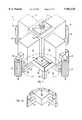
- FIG. 1is a perspective view of a microlithography system incorporating the present invention.
- FIG. 1Ais a view of a portion of the structure shown in FIG. 1 delineated by line A--A and with the reaction stage which is shown FIG. 1 removed.
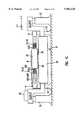
- FIG. 1Bis an elevational view, partially in section, of the structure shown in FIG. 1.
- FIG. 1Cis a schematic elevational view, partially in section, of the object positioning apparatus of the present invention.
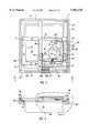
- FIG. 2is a plan view of the wafer XY stage position above the reaction stage.
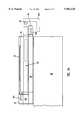
- FIG. 3is a side elevational view of a portion of the structure shown in FIG. 2 taken along line 3--3 in the direction of the arrows.
- FIG. 3Ais an enlarged view of a portion of the structure shown in FIG. 3 delineated by line B--B.
- FIG. 4is a perspective view of the reaction stage showing the XY followers without the means for coupling to the XY stage for positioning of the XY stage.
- FIG. 4Ais an enlarged perspective view of the XY followers illustrated in FIG. 4.
- FIG. 5is a schematic block diagram of the position sensing and control system for the preferred embodiment of this invention.
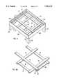
- FIGS. 6 and 7are views similar to FIGS. 2 and 3 of an alternative embodiment of the present invention.
- FIGS. 8 and 9are views similar to FIGS. 2 and 3 of still another embodiment of the present invention.
- FIG. 10is an enlarged top view of a portion of the structure shown in FIG. 8.
- FIG. 11is an end view of the structure shown in FIG. 10 taken along line 11--11 in the direction of the arrows.
- the guideless stagewith or without its isolating reaction frame, has many applications to many different types of instruments for precise positioning of objects, the present invention will be described with respect to a preferred embodiment in the form of a microlitholigraphic instrument for aligning wafers in a system where a lens produces an image which is exposed to the photoresist on the wafer surface.
- the guideless stage with or without its isolation stagecan be utilized as a guideless object stage movable in just one direction, such as a X or a Y direction
- the preferred embodimentis directed to a guideless XY wafer stage as described below.
- the optical system 12includes an illuminator 14 including a lamp LMP, such as a mercury lamp, and an ellipsoid mirror EM surrounding the lamp LPM.
- the illuminator 14comprises optical integrator such as a fly's eye lens FEL producing secondary light source images and a condenser lens CL for illuminating a reticle (mask) R with uniformed light flux.
- a mask holder RST holding the mask Ris mounted above a lens barrel PL of a projection optical system 16.
- the lens barrel PLis fixed on a part of a column assembly which is supported on a plurality of rigid arms 18 each mounted on the top portion of an isolation pad or block system 20.
- FIG. 1Bis an elevational view, partially in section, of the structure shown in FIG. 1 except that in FIG. 1B the blocks are shown as being a different configuration than in FIGS. 1 and 1A.
- FIGS. 2 and 3there are shown plan and elevational views, respectively, of the wafer supporting and positioning apparatus above the object or wafer stage base 28 including the object or wafer or XY stage 30 and the reaction frame assembly 60.
- the XY stage 30includes a support plate 32 on which the wafer 34, such as a 12 inch wafer, is supported.
- the plate 32is supported in space above the object stage base 28 via vacuum pre-load type air bearings 36 which can be controlled to adjust Z, i.e., tilt roll and focus.
- this supportcould employ combinations of magnets and coils.
- the XY stage 30also includes an appropriate element of a magnetic coupling means such as a linear drive motor for aligning the wafer with the lens of the optical system 16 for precisely positioning an image for exposure of a photoresist on the wafer's surface.
- the magnetic coupling meanstakes the form of a pair of drive members such as X drive coils 42X and 42X' for positioning the XY stage 30 in the X direction and a pair of Y drive members such as drive coils 44Y and 44Y' for positioning the XY stage 30 in the Y direction.
- the associated portion of the magnetic coupling means on the reaction frame assembly 60will be described in later detail below.
- the XY stage 30includes a pair of laser mirrors 38X operative with respect to a pair of laser beams 40A/40A' and 38Y operative with respect to a pair of laser beams 40B/40B' of a laser beam interferometer system 92 for determining and controlling the precise XY location of the XY stage relative to a fixed mirror RMX at the lower part of the lens barrel PL of the projection optical system 16.
- the reaction frame assembly 60has a reaction frame 61 which includes a plurality of support posts 62 which are mounted on the ground or a separate base substantially free from transferring vibrations between itself and the object stage.
- the reaction frame 61includes face plates 64X and 64X' extending between support posts 62 in the X direction and 66Y and 66Y' extending between support posts in the Y direction. Inside the face plates 64-66 a plurality of reaction frame rails 67-69 and 67'-69 ' are provided for supporting and guiding an X follower 72 and a Y follower 82. Inside face plate 64X are an upper follower guide rail 67 and a lower follower guide rail 68 (not shown) and on the inside surface of the opposite face plate 64X' are upper and lower follower guide rails 67' and 68'. On the inside surfaces of each of the face plates 66Y and 66Y' is a single guide rail 69 and 69', respectively, which is positioned vertically in between the guide rails 67 and 68.
- the X followerincludes a pair of spaced apart arms 74 and 74' connected at their one end by a cross piece 76.
- Drive elementssuch as drive tracks 78 and 78' (see FIG. 2) are mounted on the arms 74 and 74', respectively, for cooperating with the drive elements 42X and 42X' of the XY stage. Since in the illustrated embodiment the drive elements 42X and 42X' on the XY stage are shown as drive coils, the drive tracks on the X follower 72 take the form of magnets. The coupling elements could be reversed so that the coils would be mounted on the X follower and the magnets mounted on the XY stage.
- the laser interferometer system 92detects the new position of the XY stage momentarily and generates a position information (X coordinate value).
- a servo position control system 94under control of a host processor (CPU) 96 controls the position of the X follower 72 and the y follower 82 in response to the position information from the interferometer system 92 to follow the XY stage 30 without any connection between the drive coils 42X,42X' and the tracks 74,74'.
- the ends of the arms 74 and 74' at the side of the reaction frame 61ride or are guided on the rail 69, and the opposite ends of the arms 74 and 74' ride on rail 69' adjacent face plate 66 Y'.
- a drive member 77is provided on the cross piece 76 for cooperating with the reaction frame guide 69 for moving the follower 72 in a direction which is perpendicular to the X direction of the XY stage. Since the precision drive and control takes place in the XY stage 30, the positioning control of the X follower 72 does not have to be as accurate and provide as close tolerances and air gaps as the XY stage 30.
- the drive mechanism 77can be made of a combination of a screw shaft rotated by a motor and a nut engaged by the X follower 72 or a combination of a coil assembly and a magnet assembly to establish a linear motor and each combination can be further combined with a roller guiding mechanism.
- the Y follower 82includes a pair of arms 84 and 84' connected at their one end by a crossbar 86 and including drive tracks 88 and 88' for cooperating with the is Y drive members 44Y and 44Y'.
- the arms 84 and 84' of the Y follower 82are guided on separate guide rails.
- the ends of arm 84ride or are guided on the upper rails 67 and 67' and the ends of arm 84' are guided on lower rails 68 and 68'.
- a drive mechanism 87is provided on the cross piece 86 of the Y follower 82 for moving the Y follower 82 along guides 67, 67', 68 and 68' between the face plates 66Y and 66Y' in a direction perpendicular to the Y direction of the XY stage.
- the arms 74 and 74' and crossbar 76' of the X follower 72all lie within and move in the same plane crossing the Z axis.
- the center of gravity of the XY stage 30lies within or is immediately adjacent to this plane.
- the drive forces from each of the drive coils 42X and 42X'are in a direction along the length of the arms 74 and 74', respectively.
- the arms 84 and 84' of the Y follower 82lie within and move in different parallel planes spaced apart along the Z axis from one another respectively above and below and parallel to the plane containing the X follower 72.
- the crossbar 86lies in the lower plane containing the arm 84' and a spacer block 86' is positioned between the overlapping ends of the arm 84 and crossbar 86 to space the arms 84 and 84' in their respective parallel planes.
- the drive forces from each of the drive coils 44Y and 44Y'are in a direction along the length of the arms 84 and 84'.
- predetermined gaps in X and Z directionsare maintained between the drive coils 44Y(44Y') and the drive tracks 88(88') to achieve the guideless concept.
- the XY stage 30is positioned in an initial position relative to the projection lens as sensed by the interferometer system 92, and the XY stage 30 is supported in the desired Z direction from the object stage base 28 by the air bearings 36 with the drive coils 42X, 42X', 44Y and 44Y' spaced from the drive elements in the form of drive tracks 78, 78', 88 and 88', respectively.
- There is only indirect contact via the transmission means that deliver the signals to the coils and the laser interferometer position sensing systemwhich then transmits sensed position information to the controller which receives other commands to initiate drive signals which result in movement of the XY stage 30.
- drive signalsare sent from the position control system 94 to the appropriate drive coils, 42X, 42X', 44Y and 44Y' to drive the XY stage to a new desired position.
- the motion of the XY stageis sensed by the interferometer system 92 and position sensors 98X and 98Y (see FIG. 5), and the X follower 72 and Y follower 82 are driven by the drive members 77 and 87, respectively, to follow the XY stage.
- the position sensor 98Xdetects a variation of the Y direction space between the XY stage 30 and the X follower 72 and generates an electric signal representing the amount of space to the position control system 94.
- the position control system 94generates a proper drive signal for the drive member 77 on the basis of the X position information from the interferometer system 92 and the signal from the position sensor 98X.
- the position sensor 98Ydetects a variation of X direction space between the XY stage 30 and the Y follower 82 and generates an electric signal representing the amountof space, and the drive member 87 is energized on the basis of the Y position information from the interferometer system 92 and the signal from the position sensor 98Y.
- Yaw correctionis accomplished by the pairs of linear motors which can be used to hold or offset yaw, or the pairs of linear motors can change the rotational position of the XY stage.
- the data from either or both pairs of laser beams 40A/40A' and 40B/40B'are used to obtain yaw information.
- Electronic subtraction of digital position data obtained from measurement using the laser beams 40A and 40A' or 40B and 40B'is performed or both differences are added and divided by two.
- This inventionallows the positioning function of the XY stage to be accomplished faster than if XY guides were used. Reaction forces created in moving the XY stage can be coupled away from the image forming optics and reticle handling equipment.
- This inventionneeds no precision X or Y guides as compared to a guided stage, and precision assembly and adjustment of the wafer XY stage is reduced due to the lack of precision guides.
- the servo bandwidthis increased because the linear motor forces in the XY axes act directly on the wafer stage; they do not have to act through a guide system.
- Forces from the XY linear motorscan all be sent substantially through the center of gravity of the XY stage thereby eliminating unwanted moments of force (torque).
- any vibration of a followeris not conveyed to the wafer XY stage or to the optical system when using commercially available electromagnetic linear motors for the magnetic coupling between each of the followers 72 and 82 and the XY stage 30 and with clearance between the coils and magnet drive tracks less than about 1 mm.
- the vector sum of the moments of force at the center of gravity of the XY stage due to the positioning forces of cooperating drive membersis substantially equal to zero.
- the drive elements 42X/42x' or 42Y/42Y' of the actuator or magnetic coupling assembly for supplying electromagnetic force to the movable XY stagemay be held stationary (see FIG. 5) in a static position with respect to movement of the stage in either the X or Y direction, respectively.
- the XY stage 30is suspended on the flat smooth surface (parallel with the X-Y plane) of the stage base 28 through the air bearings 36 having air discharge ports and vacuum pre-load ports and is movable in X,Y and ⁇ direction on the stage base 28 without any friction.
- the stage base 28is supported on the foundation (or ground, base structure) 21 by the isolation blocks 20, arms 18, blocks 22, the vertical bars 26 and the horizontal bars 27.
- Each of the isolation blocks 20is composed of a vibration absorbing assembly to prevent transmission of the vibration from the foundation 21.
- FIG. 1Cis a sectional view of the XY stage 30 along a line through the drive coils 42X,42X' in Y direction, the following description is restricted about the X follower 72.
- the drive coils 42Xare disposed in a magnetic field of drive track (magnet array elongated in X direction) 78 mounted on the follower arm 74 and the drive coils 42X' are disposed in a magnetic field of drive track 78' mounted on the follower arm 74'.
- the two arms 74,74'are rigidly assembled to move together in Y direction by the guide rails 69,69' formed inside of the reaction frame 61. Also, the guide rails 69,69' restrict the movement of the two arms 74,74' in X and Z directions. And the reaction frame 61 is directly supported on the foundation 21 by the four support posts 62 independently from the stage base 28.
- the drive coils 42X(42X') and the drive tracks 78 (78')are disposed with respect to each other to maintain a predetermined gap (a few millimeters) in Y and Z directions.
- the Y drive coils 144Y and 144Y'are mounted on the arms 184 and 184' of the Y follower 182, and the X drive coil 144X is mounted on an arm 1741" of a X follower 172.
- the XY stagecan be moved to the desired XY positions.
- FIGS. 8-11there is shown an alternative embodiment of the present invention which includes links between the XY drive coils 242X, 242X', 244Y and 244Y' and the attachment to the XY stage 30'.
- These connectionsinclude a double flexure assembly 300 connecting the drive coil 244Y to one end of a connecting member 320 and a double flexure assembly 330 connecting the other end of the connecting member 320 to the XY stage 30' .
- the double flexure assembly 300includes a flange 302 connected to the coil 244Y.
- a clamping member 304is attached via clamping bolts to the flange 302 to clamp therebetween one edge of a horizontal flexible link 306.
- the other end of the flexible link 306is clamped between two horizontal members 308 which are in turn integrally connected with a vertical flange 310 to which are bolted a pair of flange members 312 which clamp one edge of a vertical flexible member 314.
- the opposite edge of the vertical flexible member 314is clamped between a pair of flange members 316 which are in turn bolted to a flange plate 318 on one end of the connecting member 320.
- a plate 348is connected to two flange members 36 which are bolted together to clamp one end of a vertical flexible member 344.
- each of the double flexure assemblies 300 and 330vibrations are reduced by providing both a horizontal and a vertical flexible member.
- the vertical flexible membersreduce X, Y and ⁇ vibrations and the horizontal flexible members reduce Z, tilt and roll vibrations.
- the coil 244Yis attached to a coil support 245Y which has an upper support plate 246 attached thereto which rides above the top of the magnetic track assembly 288.
- Vacuum pre-load type air bearings 290are provided between the coil support 245Y and upper support plate 246 on the one hand and the magnetic track assembly 288 on the other hand.
- the flexible members 306, 314, 344 and 336are stainless steel 1 1/4" wide, 1/4" long and 0.012" thick with the primary direction of flex being in the direction of the thickness.
- members 306 and 314are mounted in series with their respective primary direction of flex being orthogonal to one another; members 344 and 336 are similarly mounted.
Landscapes
- Engineering & Computer Science (AREA)
- Physics & Mathematics (AREA)
- General Physics & Mathematics (AREA)
- Condensed Matter Physics & Semiconductors (AREA)
- Manufacturing & Machinery (AREA)
- Computer Hardware Design (AREA)
- Microelectronics & Electronic Packaging (AREA)
- Power Engineering (AREA)
- Health & Medical Sciences (AREA)
- Atmospheric Sciences (AREA)
- Life Sciences & Earth Sciences (AREA)
- Toxicology (AREA)
- Environmental & Geological Engineering (AREA)
- Epidemiology (AREA)
- Public Health (AREA)
- Exposure And Positioning Against Photoresist Photosensitive Materials (AREA)
- Exposure Of Semiconductors, Excluding Electron Or Ion Beam Exposure (AREA)
- Container, Conveyance, Adherence, Positioning, Of Wafer (AREA)
- Vibration Prevention Devices (AREA)
- Details Of Measuring And Other Instruments (AREA)
Abstract
Description
This application is a continuation of U.S. patent application Ser. No. 08/627,824 filed Apr. 2, 1996, now U.S. Pat. No. 5,942,871, which is a continuation of U.S. patent application Ser. No. 08/221,375 filed Apr. 1, 1994, now U.S. Pat. No. 5,528,118.
The present invention relates, in general, to electro-mechanical alignment and isolation and, more particularly, to such method and apparatus for supporting and aligning a wafer in a microlithographic system and isolating the system from its own reaction forces and external vibrations.
Various support and positioning structures are known for use in microlithographic instruments. Typically, in the prior art, XY guides, including a separate X guide assembly and Y guide assembly, are utilized with one guide assembly mounted on and movable with the other guide assembly. Often, a separate wafer stage is mounted on top of these guide assemblies. These structures require high precision and many parts. Typically, external forces directed to parts of the positioning assembly and reaction forces due to movement of different parts of the assembly are coupled directly to the image forming optics and reticle handling equipment resulting in unwanted vibration.
U.S. Pat. No. 5,120,036 to Van Engelen et al. describes a two-step positioning device using Lorentz forces and a static gas bearing for an opto-lithographic device.
U.S. Pat. No. 4,952,858 is directed to a microlithographic apparatus utilizing electromagnetic alignment apparatus including a monolithic stage, a sub-stage and isolated reference structure in which force actuators imposed between the monolithic stage and the sub-stage are used for suspending and positioning the monolithic stage in space. In this apparatus a Y frame or stage is mounted on an X frame and the monolithic stage is positioned from and supported in space from the Y frame.
Broadly stated, the present invention is directed to method and apparatus utilizing a guideless stage for supporting an article and incorporating a reaction frame which isolates both external forces as well as reaction forces created in moving the object from other elements of the system such as a lens system which produces an image that is exposed on the photoresist of a wafer object surface.
The present invention incorporates an object stage, a reaction frame mounted on a base and substantially free from transferring vibrations between itself and the object stage, means for supporting the object stage in space independent of the reaction frame and cooperating force type linear actuator means mounted on the object stage and the reaction frame for is positioning of the object stage. The object stage can be mounted for movement in a given direction or can constitute a XY stage for movement in the X and Y directions while being supported in space in the Z direction.
A feature, an advantage of this invention is the provision of a support, positioning and isolation assembly which allows the positioning function of the object or wafer stage to be accomplished while minimizing vibrations coupled to the stage and lens systems from the reaction stage faster and with fewer parts while minimizing vibrations coupled to the stage and isolating the stage from undesired reaction forces.
In accordance with another aspect of the present invention, a positioning method and apparatus are provided for an XY stage with an independently moveable X follower and independently moveable Y follower and cooperating linear force actuators mounted between the stage and followers whereby the movement of either follower does not effect the movement of the other follower.
Another aspect of this invention is the provision on at least one follower of a pair of arms on the follower with each arm supporting a drive member and wherein the arms are positioned and movable in spaced apart planes above and below the center of gravity of the object stage.
In accordance with another aspect of the present invention, the guideless stage incorporates at least three linear force actuators with two of those actuators driving in one of the X or Y directions and the third actuators driving in the other of the X and Y directions. In accordance with the preferred embodiment of this invention the guideless stage incorporates at least four linear actuators operating between the XY stage and a reaction frame assembly with each actuator including a drive member on the XY stage so that a pair of X drive members serve to drive the XY stage in an X direction and a pair of Y drive members serve to drive the XY stage in the Y direction. The linear actuators and their drive members are constructed, positioned and controlled such that the vector sum of the moments of force at the center of gravity of the XY stage due to the positioning forces of cooperating drive members is substantially equal to zero.
These features and advantages of the present invention will become more apparent upon perusal of the following specification taken in conjunction with the following drawing wherein similar characters of reference refer to similar parts in each of the several views.
FIG. 1 is a perspective view of a microlithography system incorporating the present invention.
FIG. 1A is a view of a portion of the structure shown in FIG. 1 delineated by line A--A and with the reaction stage which is shown FIG. 1 removed.
FIG. 1B is an elevational view, partially in section, of the structure shown in FIG. 1.
FIG. 1C is a schematic elevational view, partially in section, of the object positioning apparatus of the present invention.
FIG. 2 is a plan view of the wafer XY stage position above the reaction stage.
FIG. 3 is a side elevational view of a portion of the structure shown in FIG. 2 taken alongline 3--3 in the direction of the arrows.
FIG. 3A is an enlarged view of a portion of the structure shown in FIG. 3 delineated by line B--B.
FIG. 4 is a perspective view of the reaction stage showing the XY followers without the means for coupling to the XY stage for positioning of the XY stage.
FIG. 4A is an enlarged perspective view of the XY followers illustrated in FIG. 4.
FIG. 5 is a schematic block diagram of the position sensing and control system for the preferred embodiment of this invention.
FIGS. 6 and 7 are views similar to FIGS. 2 and 3 of an alternative embodiment of the present invention.
FIGS. 8 and 9 are views similar to FIGS. 2 and 3 of still another embodiment of the present invention.
FIG. 10 is an enlarged top view of a portion of the structure shown in FIG. 8.
FIG. 11 is an end view of the structure shown in FIG. 10 taken alongline 11--11 in the direction of the arrows.
While it will be appreciated by those skilled in the art that the guideless stage, with or without its isolating reaction frame, has many applications to many different types of instruments for precise positioning of objects, the present invention will be described with respect to a preferred embodiment in the form of a microlitholigraphic instrument for aligning wafers in a system where a lens produces an image which is exposed to the photoresist on the wafer surface. In addition, while the guideless stage with or without its isolation stage can be utilized as a guideless object stage movable in just one direction, such as a X or a Y direction, the preferred embodiment is directed to a guideless XY wafer stage as described below.
Referring now to the drawings, with particular reference to is FIGS. 1 and 2, there is shown aphotolithographic instrument 10 having an upperoptical system 12 and a lower wafer support andpositioning system 13. Theoptical system 12 includes anilluminator 14 including a lamp LMP, such as a mercury lamp, and an ellipsoid mirror EM surrounding the lamp LPM. And theilluminator 14 comprises optical integrator such as a fly's eye lens FEL producing secondary light source images and a condenser lens CL for illuminating a reticle (mask) R with uniformed light flux. A mask holder RST holding the mask R is mounted above a lens barrel PL of a projectionoptical system 16. The lens barrel PL is fixed on a part of a column assembly which is supported on a plurality ofrigid arms 18 each mounted on the top portion of an isolation pad orblock system 20.
Inertial orseismic blocks 22 are located on the system such as mounted on thearms 18. Theseblocks 22 can take the form of a cast box which can be filled with sand at the operation site to avoid shipment of a massive structure. An object orwafer stage base 28 is supported from thearms 18 by depending blocks 22 and dependingbars 26 and horizontal bars 27 (see FIG. 1A). FIG. 1B is an elevational view, partially in section, of the structure shown in FIG. 1 except that in FIG. 1B the blocks are shown as being a different configuration than in FIGS. 1 and 1A.
Referring now to FIGS. 2 and 3, there are shown plan and elevational views, respectively, of the wafer supporting and positioning apparatus above the object orwafer stage base 28 including the object or wafer orXY stage 30 and thereaction frame assembly 60. TheXY stage 30 includes asupport plate 32 on which thewafer 34, such as a 12 inch wafer, is supported. Theplate 32 is supported in space above theobject stage base 28 via vacuum pre-loadtype air bearings 36 which can be controlled to adjust Z, i.e., tilt roll and focus. Alternatively, this support could employ combinations of magnets and coils.
TheXY stage 30 also includes an appropriate element of a magnetic coupling means such as a linear drive motor for aligning the wafer with the lens of theoptical system 16 for precisely positioning an image for exposure of a photoresist on the wafer's surface. In the embodiment illustrated, the magnetic coupling means takes the form of a pair of drive members such as X drive coils 42X and 42X' for positioning theXY stage 30 in the X direction and a pair of Y drive members such as drive coils 44Y and 44Y' for positioning theXY stage 30 in the Y direction. The associated portion of the magnetic coupling means on thereaction frame assembly 60 will be described in later detail below.
TheXY stage 30 includes a pair of laser mirrors 38X operative with respect to a pair oflaser beams 40A/40A' and 38Y operative with respect to a pair oflaser beams 40B/40B' of a laserbeam interferometer system 92 for determining and controlling the precise XY location of the XY stage relative to a fixed mirror RMX at the lower part of the lens barrel PL of the projectionoptical system 16.
Referring to FIGS. 4 and 4A, thereaction frame assembly 60 has areaction frame 61 which includes a plurality of support posts 62 which are mounted on the ground or a separate base substantially free from transferring vibrations between itself and the object stage.
Thereaction frame 61 includesface plates X follower 72 and aY follower 82. Insideface plate 64X are an upperfollower guide rail 67 and a lower follower guide rail 68 (not shown) and on the inside surface of theopposite face plate 64X' are upper and lower follower guide rails 67' and 68'. On the inside surfaces of each of theface plates single guide rail 69 and 69', respectively, which is positioned vertically in between the guide rails 67 and 68.
The X follower includes a pair of spaced apartarms 74 and 74' connected at their one end by across piece 76. Drive elements such as drive tracks 78 and 78' (see FIG. 2) are mounted on thearms 74 and 74', respectively, for cooperating with thedrive elements drive elements X follower 72 take the form of magnets. The coupling elements could be reversed so that the coils would be mounted on the X follower and the magnets mounted on the XY stage. As the XY stage is driven in the X and Y direction, thelaser interferometer system 92 detects the new position of the XY stage momentarily and generates a position information (X coordinate value). As described in greater detail below with reference to FIG. 5, a servoposition control system 94 under control of a host processor (CPU) 96 controls the position of theX follower 72 and they follower 82 in response to the position information from theinterferometer system 92 to follow theXY stage 30 without any connection between the drive coils 42X,42X' and thetracks 74,74'. For movably mounting theX follower 72 on thereaction frame 61, the ends of thearms 74 and 74' at the side of thereaction frame 61 ride or are guided on therail 69, and the opposite ends of thearms 74 and 74' ride on rail 69'adjacent face plate 66 Y'. For moving the X follower 72 adrive member 77 is provided on thecross piece 76 for cooperating with thereaction frame guide 69 for moving thefollower 72 in a direction which is perpendicular to the X direction of the XY stage. Since the precision drive and control takes place in theXY stage 30, the positioning control of theX follower 72 does not have to be as accurate and provide as close tolerances and air gaps as theXY stage 30. Accordingly, thedrive mechanism 77 can be made of a combination of a screw shaft rotated by a motor and a nut engaged by theX follower 72 or a combination of a coil assembly and a magnet assembly to establish a linear motor and each combination can be further combined with a roller guiding mechanism.
Similar to theX follower 72, theY follower 82 includes a pair ofarms 84 and 84' connected at their one end by acrossbar 86 and including drive tracks 88 and 88' for cooperating with the isY drive members arms 84 and 84' of theY follower 82 are guided on separate guide rails. The ends ofarm 84 ride or are guided on theupper rails 67 and 67' and the ends of arm 84' are guided onlower rails 68 and 68'. Adrive mechanism 87 is provided on thecross piece 86 of theY follower 82 for moving theY follower 82 alongguides face plates
As best illustrated in FIG. 4A, thearms 74 and 74' and crossbar 76' of theX follower 72 all lie within and move in the same plane crossing the Z axis. The center of gravity of theXY stage 30 lies within or is immediately adjacent to this plane. In this construction the drive forces from each of the drive coils 42X and 42X' are in a direction along the length of thearms 74 and 74', respectively. However, thearms 84 and 84' of theY follower 82 lie within and move in different parallel planes spaced apart along the Z axis from one another respectively above and below and parallel to the plane containing theX follower 72. In the preferred embodiment, thecrossbar 86 lies in the lower plane containing the arm 84' and a spacer block 86' is positioned between the overlapping ends of thearm 84 andcrossbar 86 to space thearms 84 and 84' in their respective parallel planes. As withX follower 72, the drive forces from each of the drive coils 44Y and 44Y' are in a direction along the length of thearms 84 and 84'. Also, predetermined gaps in X and Z directions are maintained between the drive coils 44Y(44Y') and the drive tracks 88(88') to achieve the guideless concept.
In operation of the guideless stage and isolated reaction frame of the present invention, theXY stage 30 is positioned in an initial position relative to the projection lens as sensed by theinterferometer system 92, and theXY stage 30 is supported in the desired Z direction from theobject stage base 28 by theair bearings 36 with the drive coils 42X, 42X', 44Y and 44Y' spaced from the drive elements in the form of drive tracks 78, 78', 88 and 88', respectively. There is no direct contact between theXY stage 30 and thereaction frame 61. That is, there is no path for the vibration of the reaction frame to affect the position of the XY stage and vice versa. There is only indirect contact via the transmission means that deliver the signals to the coils and the laser interferometer position sensing system which then transmits sensed position information to the controller which receives other commands to initiate drive signals which result in movement of theXY stage 30.
With the known position of theXY stage 30 from theinterferometer system 92, drive signals are sent from theposition control system 94 to the appropriate drive coils, 42X, 42X', 44Y and 44Y' to drive the XY stage to a new desired position. The motion of the XY stage is sensed by theinterferometer system 92 andposition sensors X follower 72 andY follower 82 are driven by thedrive members position sensor 98X detects a variation of the Y direction space between theXY stage 30 and theX follower 72 and generates an electric signal representing the amount of space to theposition control system 94. Theposition control system 94 generates a proper drive signal for thedrive member 77 on the basis of the X position information from theinterferometer system 92 and the signal from theposition sensor 98X.
Also, theposition sensor 98Y detects a variation of X direction space between theXY stage 30 and theY follower 82 and generates an electric signal representing the amountof space, and thedrive member 87 is energized on the basis of the Y position information from theinterferometer system 92 and the signal from theposition sensor 98Y.
Yaw correction is accomplished by the pairs of linear motors which can be used to hold or offset yaw, or the pairs of linear motors can change the rotational position of the XY stage. The data from either or both pairs oflaser beams 40A/40A' and 40B/40B' are used to obtain yaw information. Electronic subtraction of digital position data obtained from measurement using thelaser beams
This invention allows the positioning function of the XY stage to be accomplished faster than if XY guides were used. Reaction forces created in moving the XY stage can be coupled away from the image forming optics and reticle handling equipment.
This invention needs no precision X or Y guides as compared to a guided stage, and precision assembly and adjustment of the wafer XY stage is reduced due to the lack of precision guides. The servo bandwidth is increased because the linear motor forces in the XY axes act directly on the wafer stage; they do not have to act through a guide system.
Forces from the XY linear motors can all be sent substantially through the center of gravity of the XY stage thereby eliminating unwanted moments of force (torque).
With theX follower 72 and theY follower 82 mounted and moved totally independently of one another, any vibration of a follower is not conveyed to the wafer XY stage or to the optical system when using commercially available electromagnetic linear motors for the magnetic coupling between each of thefollowers XY stage 30 and with clearance between the coils and magnet drive tracks less than about 1 mm. Additionally, with the arms of one of the followers spaced above and below the arms of the other follower, the vector sum of the moments of force at the center of gravity of the XY stage due to the positioning forces of cooperating drive members is substantially equal to zero.
No connection exists between the XY stage and the follower stages that would allow vibrations to pass between them in the X, Y or θ degrees of freedom. This allows the follower stages to be mounted to a vibrating reference frame without affecting performance of the wafer stage. For example, if the reaction frame were struck by an object, the XY stage and the projection optical system would be unaffected.
It will be appreciated by a person skilled in the art that if the center of gravity is not equidistant between either of the two X drive coils or either of the two Y drive coils, that appropriate signals of differing magnitude would be sent to the respective coils to apply more force to the heavier side of the stage to drive the XY stage to the desired position.
For certain applications thedrive elements 42X/42x' or 42Y/42Y' of the actuator or magnetic coupling assembly for supplying electromagnetic force to the movable XY stage may be held stationary (see FIG. 5) in a static position with respect to movement of the stage in either the X or Y direction, respectively.
In the last of the explanation of this embodiment, referring to FIG. 1C again, the essential structure of the present invention will be described. As illustrated in FIG. 1C, theXY stage 30 is suspended on the flat smooth surface (parallel with the X-Y plane) of thestage base 28 through theair bearings 36 having air discharge ports and vacuum pre-load ports and is movable in X,Y and θ direction on thestage base 28 without any friction.
Thestage base 28 is supported on the foundation (or ground, base structure) 21 by the isolation blocks 20,arms 18, blocks 22, thevertical bars 26 and thehorizontal bars 27. Each of the isolation blocks 20 is composed of a vibration absorbing assembly to prevent transmission of the vibration from thefoundation 21.
Since FIG. 1C is a sectional view of theXY stage 30 along a line through the drive coils 42X,42X' in Y direction, the following description is restricted about theX follower 72.
In FIG. 1C, the drive coils 42X are disposed in a magnetic field of drive track (magnet array elongated in X direction) 78 mounted on thefollower arm 74 and the drive coils 42X' are disposed in a magnetic field of drive track 78' mounted on the follower arm 74'.
The twoarms 74,74' are rigidly assembled to move together in Y direction by the guide rails 69,69' formed inside of thereaction frame 61. Also, the guide rails 69,69' restrict the movement of the twoarms 74,74' in X and Z directions. And thereaction frame 61 is directly supported on thefoundation 21 by the foursupport posts 62 independently from thestage base 28.
Therefore, the drive coils 42X(42X') and the drive tracks 78 (78') are disposed with respect to each other to maintain a predetermined gap (a few millimeters) in Y and Z directions.
Accordingly, when the drive coils 42X,42X' are energized to move theXY stage 30 in X direction, the reaction force generated on the drive tracks 78,78' is transferred to thefoundation 21, not to theXY stage 30.
On the other hand, as theXY stage 30 moves in Y direction, the twoarms 74,74' are moved in Y direction by thedrive member 77 such that each of the drive tracks 78,78' followsrespective coils position sensor 98X.
While the present invention has been described with reference to the preferred embodiment having a pair of X drive members orcoils coils stage 130 and a single X drive coil orlinear motor 142X is mounted centered at the center of gravity CG ' of the XY stage. The Y drive coils 144Y and 144Y' are mounted on thearms 184 and 184' of theY follower 182, and the X drive coil 144X is mounted on an arm 1741" of aX follower 172. By applying appropriate drive signals to the drive coils 142X and 144Y and 144Y', the XY stage can be moved to the desired XY positions.
Referring now to FIGS. 8-11, there is shown an alternative embodiment of the present invention which includes links between the XY drive coils 242X, 242X', 244Y and 244Y' and the attachment to theXY stage 30'. These connections include adouble flexure assembly 300 connecting thedrive coil 244Y to one end of a connectingmember 320 and adouble flexure assembly 330 connecting the other end of the connectingmember 320 to theXY stage 30' . Thedouble flexure assembly 300 includes aflange 302 connected to thecoil 244Y. A clampingmember 304 is attached via clamping bolts to theflange 302 to clamp therebetween one edge of a horizontalflexible link 306. The other end of theflexible link 306 is clamped between twohorizontal members 308 which are in turn integrally connected with avertical flange 310 to which are bolted a pair offlange members 312 which clamp one edge of a verticalflexible member 314. The opposite edge of the verticalflexible member 314 is clamped between a pair offlange members 316 which are in turn bolted to aflange plate 318 on one end of the connectingmember 320. At the other end of the connecting member 320 aplate 348 is connected to twoflange members 36 which are bolted together to clamp one end of a verticalflexible member 344. The opposite edge of thevertical member 344 is clamped byflange members 342 which are in turn connected to aplate 340 connected to a pair of clampingplates 338 clamping one edge of a horizontalflexible member 336, the opposing edge of which is in turn clamped onto theXY stage 30' with the aid of theplate 334. Thus, in each of thedouble flexure assemblies
As illustrated in FIG. 11, thecoil 244Y is attached to acoil support 245Y which has anupper support plate 246 attached thereto which rides above the top of themagnetic track assembly 288. Vacuum pre-loadtype air bearings 290 are provided between thecoil support 245Y andupper support plate 246 on the one hand and themagnetic track assembly 288 on the other hand.
In an operative example of the embodiment illustrated in FIGS. 8-11 theflexible members stainless steel 1 1/4" wide, 1/4" long and 0.012" thick with the primary direction of flex being in the direction of the thickness. In the embodiment illustratedmembers members
While the present invention has been described in terms of the preferred embodiment, the invention can take many different forms and is only limited by the scope of the following claims.
Claims (84)
1. A microlithography apparatus for exposing an image onto a surface of an object through a projection optical system, the apparatus comprising:
a plurality of isolation blocks for resting on a foundation, the isolation blocks being mounted to a support structure which supports the projection optical system;
a stage base mounted to the support structure and disposed under the projection optical system;
a stage supported on a surface of the stage base by a bearing system, the stage being movable on the stage base relative to an image projected by the projection optical system;
a frame resting on the foundation independently from the support structure and the stage base;
an arm member guided on the frame so as to move alongside the stage without contacting the stage; and
a drive assembly disposed between the stage and the arm member, the drive assembly including a coil mounted to one of the stage and arm member and a cooperating magnet assembly mounted to the other of the stage and arm member.
2. The microlithography apparatus of claim 1, further comprising a location system for determining a location of the stage and which has a movable portion mounted to the stage and a stationary portion mounted to the support structure.
3. The microlithography apparatus of claim 1, further comprising a second drive assembly disposed between the arm member and the frame so as move the arm member relative to the frame.
4. A positioning system for positioning an object relative to a projected image, comprising:
a stage for holding the object;
a drive assembly for moving the stage relative to the projected image; and
a location system for determining a position of the stage relative to a source of the projected image;
the drive assembly comprising a stationary element mounted to a frame of the positioning system, the location system comprising a stationary portion and a movable portion which is mounted to the stage for cooperation with the stationary portion of the location system, the stationary portion of the location system being mounted to a support structure of the positioning system, the support structure being dynamically isolated from the frame.
5. The positioning system of claim 4, wherein the source of the projected image includes a lens mounted to the support structure.
6. The positioning system of claim 4, further comprising a stage base on which the stage moves, wherein the stage base and the source of the projected image are mounted to the support structure.
7. A microlithography apparatus comprising:
a stage;
a projection system defining a main axis;
a drive assembly for moving the stage relative to the projection system in at least one direction orthogonal to the main axis; and
a location system for determining a position of the stage relative to the projection system;
the drive assembly comprising a stationary element mounted to a frame of the apparatus, the location system comprising a stationary portion and a movable portion which is mounted to the stage for cooperation with the stationary portion of the location system, the stationary portion of the location system being mounted to a support structure of the apparatus, the support structure being dynamically isolated from the frame.
8. The microlithography apparatus of claim 7, wherein the projection system is mounted to the support structure.
9. The microlithography apparatus of claim 7, wherein the projection system and a base on which the stage moves are mounted to the support structure.
10. An exposure apparatus which forms an image onto an object, comprising:
an irradiation apparatus that irradiates the image onto the object;
a support structure;
a movable stage;
a reaction frame which is dynamically isolated from the support structure, wherein a reaction force caused by the movement of the movable stage is transferred to the reaction frame; and
a position detector to detect a position of the stages the position detector being supported by the support structure.
11. The exposure apparatus of claim 10, wherein the support structure supports the irradiation apparatus.
12. The exposure apparatus of claim 11, wherein the irradiation apparatus includes a projection system which projects the image.
13. The exposure apparatus of claim 12, wherein the projection system optically projects the image.
14. The exposure apparatus of claim 12, wherein the movable stage is located below the projection system.
15. The exposure apparatus of claim 12, wherein the position detector projects a light beam to a first mirror provided on the movable stage and a second mirror provided on the projection system.
16. The exposure apparatus of claim 11, wherein the irradiation apparatus includes a mask holder which holds a mask which defines the image.
17. The exposure apparatus of claim 10, wherein the support structure has a first portion which supports the movable stage and a second portion which supports the irradiation apparatus.
18. The exposure apparatus of claim 17, wherein the first portion and the second portion are connected rigidly to each other.
19. The exposure apparatus of claim 10, wherein the position detector is an interferometer system.
20. The exposure apparatus of claim 10, wherein the position detector projects a light beam to a mirror provided on the movable stage and to a second mirror provided on the irradiation apparatus.
21. The exposure apparatus of claim 10, wherein the movable stage is provided on the support structure.
22. The exposure apparatus of claim 10, wherein the support structure is supported on a foundation.
23. The exposure apparatus of claim 22, wherein the support structure is supported on the foundation with a block between the support structure and the foundation.
24. The exposure apparatus of claim 23, wherein the block comprises a vibration absorbing assembly thereby preventing transmission of vibration from the foundation.
25. The exposure apparatus of claim 22, wherein the foundation is the ground or a base structure.
26. The exposure apparatus of claim 10, wherein the movable stage is a guideless stage having no associated guide member to guide its movement.
27. The exposure apparatus of claim 26, wherein the support structure includes a base member and the guidelines stage is movable over a surface of the base member on a bearing.
28. The exposure apparatus of claim 27, wherein the bearing is a non-contact bearing which supports the guideless stage.
29. The exposure apparatus of claim 28, wherein the bearing comprises an air bearing.
30. The exposure apparatus of claim 28, wherein the bearing includes a magnet and a cooperating coil.
31. The exposure apparatus of claim 10, wherein the movable stage is a wafer stage on which the object is supported.
32. The exposure apparatus of claim 31, wherein the support structures includes a base member and the wafer stage is movable over a surface of the base member on a bearing.
33. The exposure apparatus of claim 32, wherein the bearing is a non-contact bearing which supports the wafer stage.
34. The exposure apparatus of claim 33, wherein the bearing comprises an air bearing.
35. The exposure apparatus of claim 33, wherein the bearing includes a magnet and a cooperating coil.
36. The exposure apparatus of claim 10, wherein the reaction frame supports at least part of a drive, which moves the movable stage.
37. The exposure apparatus of claim 36, wherein the drive comprises a linear motor.
38. The exposure apparatus of claim 37, wherein the drive rotates the movable stage on an axis of the movable stare.
39. The exposure apparatus of claim 38, wherein the drive moves the movable stage based on a detection result by the position detector so as to effect yaw correction.
40. The exposure apparatus of claim 38, wherein the movable stage is a guideless stage, thereby having no associated guide member to guide its movement.
41. The exposure apparatus of claim 38, wherein the movable stage is a wafer stage on which the object is supported.
42. The exposure apparatus of claim 36, wherein the drive moves the movable stage in a two dimensional plane, including movement in the plane in a first linear direction, a second linear direction and a rotative direction on an axis of the movable stage.
43. The exposure apparatus of claim 42, wherein the drive moves the movable stage based on a detection result by the position detector so as to effect yaw correction.
44. The exposure apparatus of claim 42, wherein the movable stage is a guideless stage having no associated guide member to guide its movement.
45. The exposure apparatus of claim 42, wherein the movable stage is a wafer stage on which the object is supported.
46. An exposure apparatus which forms an image onto an object, comprising:
an irradiation apparatus that irradiates the image onto the object;
a movable stage;
a first support structure;
a second support structure dynamically isolated from the first support structure;
a drive to move the stage such that a reaction force exerted by the movement of the movable stage is transferred to the first support structure; and
a position detector to detect a position of the movable stage, the position detector being supported by the second support structure.
47. The exposure apparatus of claim 46, wherein the second support structure supports the irradiation apparatus.
48. The exposure apparatus of claim 47, wherein the irradiation apparatus includes a projection system which projects the image.
49. The exposure apparatus of claim 48, wherein the projection system optically projects the image.
50. The exposure apparatus of claim 48, wherein the movable stage is located below the projection system.
51. The exposure apparatus of claim 48, wherein the position detector projects a light beam to a first mirror provided on the movable stage and to a second mirror provided on the projection system.
52. The exposure apparatus of claim 47, wherein the irradiation apparatus includes a mask holder which holds a mask which defines the image.
53. The exposure apparatus of claim 46, wherein the second support structure has a first portion which supports the movable stage and a second portion which supports the irradiation apparatus.
54. The exposure apparatus of claim 53, wherein the first portion and the second portion are connected rigidly to each other.
55. The exposure apparatus of claim 46, wherein the movable stage is a guideless stage having no associated guide member to guide its movement.
56. The exposure apparatus of claim 46, wherein the movable stage is a wafer stage on which the object is supported.
57. The exposure apparatus of claim 46, wherein the movable stage is supported on the second support structure.
58. The exposure apparatus of claim 57, wherein the movable stage is a guideless stage having no associated guide member to guide its movement.
59. The exposure apparatus of claim 58, wherein the second support structure includes a base member and the guideless stage is movable over a surface of the base member on a bearing.
60. The exposure apparatus of claim 59, wherein the bearing is a non-contact bearing which supports the guideless stage.
61. The exposure apparatus of claim 60, wherein the bearing comprises an air bearing.
62. The exposure apparatus of claim 60, wherein the bearing includes a magnet and a cooperating coil.
63. The exposure apparatus of claim 57, wherein the movable stage is a wafer stage on which the object is supported.
64. The exposure apparatus of claim 63, wherein the second support structure includes a base member and the wafer is movable over a surface of the base member on a bearing.
65. The exposure apparatus of claim 64, wherein the bearing is a non-contact bearing which supports the wafer stage.
66. The exposure apparatus of claim 65, wherein the bearing comprises an air bearing.
67. The exposure apparatus of claim 65, wherein the bearing includes a magnet and a cooperating coil.
68. The exposure apparatus of claim 46, wherein the second support structure is supported on a foundation.
69. The exposure apparatus of claim 68, wherein the second support structure is supported on the foundation with a block between the second support structure and the foundation.
70. The exposure apparatus of claim 69, wherein the block comprises a vibration absorbing assembly thereby preventing transmission of vibration from the foundation.
71. The exposure apparatus of claim 70, wherein the foundation is the ground or a base structure.
72. The exposure apparatus of claim 46, wherein the drive comprises a linear motor.
73. The exposure apparatus of claim 46, wherein the drive rotates the movable stage on an axis of the movable stage.
74. The exposure apparatus of claim 73, wherein the drive moves the movable stage based on a detection result by the position detector so as to effect yaw correction.
75. The exposure apparatus of claim 73, wherein the movable stage is a guideless stage having no associated guide member to guide its movement.
76. The exposure apparatus of claim 73, wherein the movable stage is a wafer stage on which the object is supported.
77. The exposure apparatus of claim 46, wherein the drive moves the movable stage in a two dimensional plane, including movement in the plane in a first linear direction, a second linear direction and a rotative direction on an axis of the movable stage.
78. The exposure apparatus of claim 77, wherein the drive moves the movable stage based on a detection result by the position detector so as to effect yaw correction.
79. The exposure apparatus of claim 77, wherein the movable stage is a guideless stage having no associated guide member to guide its movement.
80. The exposure apparatus of claim 77, wherein the movable stage is a wafer stage on which the object is supported.
81. The exposure apparatus of claim 46, wherein the position detector is an interferometer system.
82. The exposure apparatus of claim 46, wherein the position detector projects a light beam to a mirror provided on the movable stage.
83. The exposure apparatus of claim 46, wherein the first support structure is supported on a foundation.
84. The exposure apparatus of claim 46, wherein the first support structure supports at least part of the drive.
Priority Applications (1)
| Application Number | Priority Date | Filing Date | Title |
|---|---|---|---|
| US09/018,593US5982128A (en) | 1994-04-01 | 1998-02-04 | Lithography apparatus with movable stage and mechanical isolation of stage drive |
Applications Claiming Priority (3)
| Application Number | Priority Date | Filing Date | Title |
|---|---|---|---|
| US08/221,375US5528118A (en) | 1994-04-01 | 1994-04-01 | Guideless stage with isolated reaction stage |
| US08/627,824US5942871A (en) | 1994-04-01 | 1996-04-02 | Double flexure support for stage drive coil |
| US09/018,593US5982128A (en) | 1994-04-01 | 1998-02-04 | Lithography apparatus with movable stage and mechanical isolation of stage drive |
Related Parent Applications (1)
| Application Number | Title | Priority Date | Filing Date |
|---|---|---|---|
| US08/627,824ContinuationUS5942871A (en) | 1994-04-01 | 1996-04-02 | Double flexure support for stage drive coil |
Publications (1)
| Publication Number | Publication Date |
|---|---|
| US5982128Atrue US5982128A (en) | 1999-11-09 |
Family
ID=22827557
Family Applications (8)
| Application Number | Title | Priority Date | Filing Date |
|---|---|---|---|
| US08/221,375Expired - LifetimeUS5528118A (en) | 1994-04-01 | 1994-04-01 | Guideless stage with isolated reaction stage |
| US08/627,824Expired - LifetimeUS5942871A (en) | 1994-04-01 | 1996-04-02 | Double flexure support for stage drive coil |
| US08/668,584Expired - LifetimeUS5744924A (en) | 1994-04-01 | 1996-06-20 | Guideless stage with isolated reaction frame |
| US09/018,593Expired - LifetimeUS5982128A (en) | 1994-04-01 | 1998-02-04 | Lithography apparatus with movable stage and mechanical isolation of stage drive |
| US09/127,288Expired - LifetimeUS6049186A (en) | 1994-04-01 | 1998-07-31 | Method for making and operating an exposure apparatus having a reaction frame |
| US09/310,925Expired - LifetimeUS6281654B1 (en) | 1994-04-01 | 1999-05-13 | Method for making apparatus with dynamic support structure isolation and exposure method |
| US09/437,608Expired - LifetimeUS6271640B1 (en) | 1994-04-01 | 1999-11-10 | Exposure apparatus having reaction frame |
| US09/880,859Expired - Fee RelatedUS6841965B2 (en) | 1994-04-01 | 2001-06-15 | Guideless stage with isolated reaction stage |
Family Applications Before (3)
| Application Number | Title | Priority Date | Filing Date |
|---|---|---|---|
| US08/221,375Expired - LifetimeUS5528118A (en) | 1994-04-01 | 1994-04-01 | Guideless stage with isolated reaction stage |
| US08/627,824Expired - LifetimeUS5942871A (en) | 1994-04-01 | 1996-04-02 | Double flexure support for stage drive coil |
| US08/668,584Expired - LifetimeUS5744924A (en) | 1994-04-01 | 1996-06-20 | Guideless stage with isolated reaction frame |
Family Applications After (4)
| Application Number | Title | Priority Date | Filing Date |
|---|---|---|---|
| US09/127,288Expired - LifetimeUS6049186A (en) | 1994-04-01 | 1998-07-31 | Method for making and operating an exposure apparatus having a reaction frame |
| US09/310,925Expired - LifetimeUS6281654B1 (en) | 1994-04-01 | 1999-05-13 | Method for making apparatus with dynamic support structure isolation and exposure method |
| US09/437,608Expired - LifetimeUS6271640B1 (en) | 1994-04-01 | 1999-11-10 | Exposure apparatus having reaction frame |
| US09/880,859Expired - Fee RelatedUS6841965B2 (en) | 1994-04-01 | 2001-06-15 | Guideless stage with isolated reaction stage |
Country Status (4)
| Country | Link |
|---|---|
| US (8) | US5528118A (en) |
| JP (4) | JP3731218B2 (en) |
| KR (3) | KR100291820B1 (en) |
| GB (1) | GB2288277B (en) |
Cited By (43)
| Publication number | Priority date | Publication date | Assignee | Title |
|---|---|---|---|---|
| US6271640B1 (en)* | 1994-04-01 | 2001-08-07 | Nikon Corporation | Exposure apparatus having reaction frame |
| US6316901B2 (en) | 1995-04-04 | 2001-11-13 | Nikon Corporation | Exposure apparatus and method utilizing isolated reaction frame |
| US6320649B1 (en)* | 1998-02-04 | 2001-11-20 | Canon Kabushiki Kaisha | Stage system for exposure apparatus |
| US6327024B1 (en) | 1994-10-11 | 2001-12-04 | Nikon Corporation | Vibration isolation apparatus for stage |
| US6359679B1 (en)* | 1999-01-11 | 2002-03-19 | Canon Kabushiki Kaisha | Positioning device, exposure device, and device manufacturing method |
| US6469773B1 (en)* | 1997-12-10 | 2002-10-22 | Canon Kabushiki Kaisha | Stage apparatus, exposure apparatus and device manufacturing method |
| US6496248B2 (en) | 2000-12-15 | 2002-12-17 | Nikon Corporation | Stage device and exposure apparatus and method |
| US6525803B2 (en)* | 1999-12-21 | 2003-02-25 | Asml Netherlands B.V. | Balanced positioning system for use in lithographic apparatus |
| US6555829B1 (en)* | 2000-01-10 | 2003-04-29 | Applied Materials, Inc. | High precision flexure stage |
| US6570644B2 (en) | 2001-06-05 | 2003-05-27 | Nikon Corporation | Connection assembly of wafer stage chamber |
| US6607157B1 (en)* | 1999-07-14 | 2003-08-19 | Keltech Engineering, Inc. | Air bearing system with an air cylinder web dancer system or idler rolls |
| US20030173556A1 (en)* | 2002-03-18 | 2003-09-18 | Watson Douglas C. | Compensating for cable drag forces in high precision stages |
| US20030213919A1 (en)* | 2002-05-16 | 2003-11-20 | Hazelton Andrew J. | Reaction frame apparatus and method |
| US20030218398A1 (en)* | 2002-05-24 | 2003-11-27 | Greene Philip M. | Reaction force transfer system |
| WO2003017339A3 (en)* | 2001-08-14 | 2003-11-27 | Applied Materials Inc | Method and apparatus for positoning a wafer chuck |
| WO2003104678A1 (en)* | 2002-06-10 | 2003-12-18 | Canadian Space Agency | Vibration control apparatus |
| US6744228B1 (en) | 1998-09-18 | 2004-06-01 | Gsi Lumonics Corp. | High-speed precision positioning apparatus |
| US6836093B1 (en)* | 1999-12-21 | 2004-12-28 | Nikon Corporation | Exposure method and apparatus |
| US20050073668A1 (en)* | 2003-10-03 | 2005-04-07 | Canon Kabushiki Kaisha | Stage device, exposure apparatus and device manufacturing method |
| US6927840B2 (en) | 1994-04-01 | 2005-08-09 | Nikon Corporation | Positioning device having dynamically isolated frame, and lithographic device provided with such a positioning device |
| US20050200243A1 (en)* | 1994-01-27 | 2005-09-15 | Active Control Experts, Inc. | Method and device for vibration control |
| US20060065372A1 (en)* | 2004-09-24 | 2006-03-30 | Kabushiki Kaisha Shinkawa | Bonding apparatus |
| US20070252969A1 (en)* | 2003-04-18 | 2007-11-01 | Advantest Corporation | Stage apparatus and exposure apparatus |
| US20070263185A1 (en)* | 2003-02-26 | 2007-11-15 | Nikon Corporation | Exposure apparatus, exposure method, and method for producing device |
| US20080073982A1 (en)* | 2004-12-24 | 2008-03-27 | Nikon Corporation | Magnetic Guide Apparatus, Stage Apparatus, Exposure Apparatus, and Device Manufacturing Method |
| US20080143994A1 (en)* | 2004-04-09 | 2008-06-19 | Nikon Corporation | Drive Method of Moving Body, Stage Unit, and Exposure Apparatus |
| US20080309276A1 (en)* | 2007-06-18 | 2008-12-18 | Xradia, Inc. | Five Axis Compensated Rotating Stage |
| US7812925B2 (en) | 2003-06-19 | 2010-10-12 | Nikon Corporation | Exposure apparatus, and device manufacturing method |
| US7855777B2 (en) | 2003-07-09 | 2010-12-21 | Nikon Corporation | Exposure apparatus and method for manufacturing device |
| US20110022227A1 (en)* | 2009-07-23 | 2011-01-27 | Kla-Tencor Corporation | Dual Scanning Stage |
| US8035795B2 (en) | 2003-04-11 | 2011-10-11 | Nikon Corporation | Apparatus and method for maintaining immersion fluid in the gap under the protection lens during wafer exchange in an immersion lithography machine |
| US8045136B2 (en) | 2004-02-02 | 2011-10-25 | Nikon Corporation | Stage drive method and stage unit, exposure apparatus, and device manufacturing method |
| US20110260383A1 (en)* | 2010-04-21 | 2011-10-27 | Seagate Technology Llc | Noncontact positioning of a workpiece |
| US8072576B2 (en) | 2003-05-23 | 2011-12-06 | Nikon Corporation | Exposure apparatus and method for producing device |
| US8085381B2 (en) | 2003-04-11 | 2011-12-27 | Nikon Corporation | Cleanup method for optics in immersion lithography using sonic device |
| US8384874B2 (en) | 2004-07-12 | 2013-02-26 | Nikon Corporation | Immersion exposure apparatus and device manufacturing method to detect if liquid on base member |
| US8451424B2 (en) | 2003-07-28 | 2013-05-28 | Nikon Corporation | Exposure apparatus, method for producing device, and method for controlling exposure apparatus |
| US8520184B2 (en) | 2004-06-09 | 2013-08-27 | Nikon Corporation | Immersion exposure apparatus and device manufacturing method with measuring device |
| US20140074297A1 (en)* | 2012-09-10 | 2014-03-13 | Canon Kabushiki Kaisha | Control device, actuator including control device, image blur correction device, replacement lens, imaging device and automatic stage |
| US20140183806A1 (en)* | 2012-12-31 | 2014-07-03 | Memc Electronic Materials, Inc. | System and method for aligning an ingot with mounting block |
| US9272442B2 (en) | 2012-12-31 | 2016-03-01 | Sunedison, Inc. | Methods for aligning an ingot with mounting block |
| US10184607B2 (en) | 2016-05-18 | 2019-01-22 | Aerotech, Inc. | Open frame, parallel, two axis flexure stage with yaw compensation |
| US20190264786A1 (en)* | 2016-07-21 | 2019-08-29 | Florian Valentin ILE | Device for the Angular Positioning of a Shaft |
Families Citing this family (307)
| Publication number | Priority date | Publication date | Assignee | Title |
|---|---|---|---|---|
| US7365513B1 (en) | 1994-04-01 | 2008-04-29 | Nikon Corporation | Positioning device having dynamically isolated frame, and lithographic device provided with such a positioning device |
| US6721034B1 (en) | 1994-06-16 | 2004-04-13 | Nikon Corporation | Stage unit, drive table, and scanning exposure apparatus using the same |
| US6246204B1 (en) | 1994-06-27 | 2001-06-12 | Nikon Corporation | Electromagnetic alignment and scanning apparatus |
| JP3800616B2 (en)* | 1994-06-27 | 2006-07-26 | 株式会社ニコン | Target moving device, positioning device, and movable stage device |
| US6134981A (en) | 1999-12-03 | 2000-10-24 | Nikon Research Corporation Of America | Precision scanning apparatus and method with fixed and movable guide members |
| US6008500A (en)* | 1995-04-04 | 1999-12-28 | Nikon Corporation | Exposure apparatus having dynamically isolated reaction frame |
| TW318255B (en) | 1995-05-30 | 1997-10-21 | Philips Electronics Nv | |
| US6392741B1 (en) | 1995-09-05 | 2002-05-21 | Nikon Corporation | Projection exposure apparatus having active vibration isolator and method of controlling vibration by the active vibration isolator |
| JP3548353B2 (en)* | 1996-10-15 | 2004-07-28 | キヤノン株式会社 | Stage apparatus, exposure apparatus and device manufacturing method using the same |
| US6330052B1 (en)* | 1997-06-13 | 2001-12-11 | Canon Kabushiki Kaisha | Exposure apparatus and its control method, stage apparatus, and device manufacturing method |
| US6522386B1 (en) | 1997-07-24 | 2003-02-18 | Nikon Corporation | Exposure apparatus having projection optical system with aberration correction element |
| US20010003028A1 (en) | 1997-09-19 | 2001-06-07 | Nikon Corporation | Scanning Exposure Method |
| KR20010030903A (en) | 1997-11-12 | 2001-04-16 | 오노 시게오 | Projection exposure apparatus |
| AU1691899A (en)* | 1997-12-26 | 1999-07-19 | Nikon Corporation | Exposure apparatus, method of producing the apparatus, and exposure method, and device and method of manufacturing the device |
| JPH11191585A (en)* | 1997-12-26 | 1999-07-13 | Canon Inc | Stage apparatus, exposure apparatus using the same, and device manufacturing method |
| KR100638533B1 (en) | 1998-02-09 | 2006-10-26 | 가부시키가이샤 니콘 | Substrate Supporting Device, Substrate Carrying Device and Method, Substrate Exchange Method, and Exposure Device and Manufacturing Method |
| US6327039B1 (en)* | 1998-02-23 | 2001-12-04 | Zygo Corporation | Interferometer and method for measuring the refractive index and optical path length effects of air |
| US5959427A (en)* | 1998-03-04 | 1999-09-28 | Nikon Corporation | Method and apparatus for compensating for reaction forces in a stage assembly |
| US6260282B1 (en)* | 1998-03-27 | 2001-07-17 | Nikon Corporation | Stage control with reduced synchronization error and settling time |
| JP4362975B2 (en) | 1998-04-10 | 2009-11-11 | 株式会社ニコン | Linear motor coil, coil, linear motor, electric motor, linear motor manufacturing method, electric motor manufacturing method, stage apparatus, exposure apparatus |
| US6693713B1 (en) | 1998-07-22 | 2004-02-17 | Nikon Corporation | Mark detection method, exposure method, device manufacturing method, mark detection apparatus, exposure apparatus, and device |
| US6252234B1 (en)* | 1998-08-14 | 2001-06-26 | Nikon Corporation | Reaction force isolation system for a planar motor |
| US6188147B1 (en) | 1998-10-02 | 2001-02-13 | Nikon Corporation | Wedge and transverse magnet arrays |
| US6208045B1 (en) | 1998-11-16 | 2001-03-27 | Nikon Corporation | Electric motors and positioning devices having moving magnet arrays and six degrees of freedom |
| US6147421A (en)* | 1998-11-16 | 2000-11-14 | Nikon Corporation | Platform positionable in at least three degrees of freedom by interaction with coils |
| US6104108A (en)* | 1998-12-22 | 2000-08-15 | Nikon Corporation | Wedge magnet array for linear motor |
| EP1059021B1 (en)* | 1998-12-29 | 2005-03-09 | Assembléon N.V. | Component placement machine |
| JP2000232249A (en)* | 1999-02-10 | 2000-08-22 | Nikon Corp | Laser output control method, laser device and exposure device |
| US6114781A (en)* | 1999-02-26 | 2000-09-05 | Nikon Corporation | Cooling system for a linear or planar motor |
| US6334960B1 (en) | 1999-03-11 | 2002-01-01 | Board Of Regents, The University Of Texas System | Step and flash imprint lithography |
| US7114693B1 (en) | 1999-04-08 | 2006-10-03 | Applied Materials, Inc. | Stable cell platform |
| US6551484B2 (en) | 1999-04-08 | 2003-04-22 | Applied Materials, Inc. | Reverse voltage bias for electro-chemical plating system and method |
| US6571657B1 (en) | 1999-04-08 | 2003-06-03 | Applied Materials Inc. | Multiple blade robot adjustment apparatus and associated method |
| AU4704200A (en) | 1999-05-04 | 2000-11-17 | O'hagins, Inc. | Roof ventilation system and method |
| US6762412B1 (en) | 1999-05-10 | 2004-07-13 | Nikon Corporation | Optical apparatus, exposure apparatus using the same, and gas introduction method |
| US6144119A (en)* | 1999-06-18 | 2000-11-07 | Nikon Corporation | Planar electric motor with dual coil and magnet arrays |
| US6163091A (en)* | 1999-07-06 | 2000-12-19 | Nikon Corporation | Linear motor with commutation coil |
| US20030213772A9 (en)* | 1999-07-09 | 2003-11-20 | Mok Yeuk-Fai Edwin | Integrated semiconductor substrate bevel cleaning apparatus and method |
| JP3616543B2 (en)* | 1999-09-10 | 2005-02-02 | 日本電気株式会社 | XY stage |
| US8429005B2 (en) | 1999-09-23 | 2013-04-23 | Activ8Now, Llc | Method for determining effectiveness of display of objects in advertising images |
| US6549277B1 (en) | 1999-09-28 | 2003-04-15 | Nikon Corporation | Illuminance meter, illuminance measuring method and exposure apparatus |
| US6324933B1 (en) | 1999-10-06 | 2001-12-04 | Agere Systems Guardian Corp. | Planar movable stage mechanism |
| US6873087B1 (en) | 1999-10-29 | 2005-03-29 | Board Of Regents, The University Of Texas System | High precision orientation alignment and gap control stages for imprint lithography processes |
| US6355994B1 (en)* | 1999-11-05 | 2002-03-12 | Multibeam Systems, Inc. | Precision stage |
| JP2001148341A (en) | 1999-11-19 | 2001-05-29 | Nikon Corp | Exposure equipment |
| DE60032568T2 (en)* | 1999-12-01 | 2007-10-04 | Asml Netherlands B.V. | Positioning apparatus and lithographic apparatus provided therewith |
| US6791661B2 (en) | 1999-12-09 | 2004-09-14 | Nikon Corporation | Gas replacement method and apparatus, and exposure method and apparatus |
| EP1248288A1 (en)* | 1999-12-16 | 2002-10-09 | Nikon Corporation | Exposure method and exposure apparatus |
| TW546551B (en)* | 1999-12-21 | 2003-08-11 | Asml Netherlands Bv | Balanced positioning system for use in lithographic apparatus |
| US6271606B1 (en)* | 1999-12-23 | 2001-08-07 | Nikon Corporation | Driving motors attached to a stage that are magnetically coupled through a chamber |
| JP2001209188A (en) | 2000-01-27 | 2001-08-03 | Nikon Corp | Scanning exposure apparatus, scanning exposure method, and mask |
| TW495836B (en) | 2000-02-02 | 2002-07-21 | Nikon Corp | Scanning exposure method and device |
| EP1128216B1 (en)* | 2000-02-21 | 2008-11-26 | Sharp Kabushiki Kaisha | Precision stage device |
| US6408767B1 (en)* | 2000-03-01 | 2002-06-25 | Nikon Corporation | Low stiffness suspension for a stage |
| JP2001297960A (en) | 2000-04-11 | 2001-10-26 | Nikon Corp | Stage equipment and exposure equipment |
| US6486941B1 (en)* | 2000-04-24 | 2002-11-26 | Nikon Corporation | Guideless stage |
| US6405659B1 (en) | 2000-05-01 | 2002-06-18 | Nikon Corporation | Monolithic stage |
| US6913680B1 (en) | 2000-05-02 | 2005-07-05 | Applied Materials, Inc. | Method of application of electrical biasing to enhance metal deposition |
| JP2004513221A (en) | 2000-05-23 | 2004-04-30 | アプライド マテリアルズ インコーポレイテッド | Method and apparatus for overcoming copper seed layer anomalies and adjusting surface feature size and aspect ratio |
| US6496060B2 (en) | 2000-06-15 | 2002-12-17 | Nikon Corporation | Hybridized, high performance PWM amplifier |
| US6445093B1 (en) | 2000-06-26 | 2002-09-03 | Nikon Corporation | Planar motor with linear coil arrays |
| US6452292B1 (en) | 2000-06-26 | 2002-09-17 | Nikon Corporation | Planar motor with linear coil arrays |
| US6576110B2 (en) | 2000-07-07 | 2003-06-10 | Applied Materials, Inc. | Coated anode apparatus and associated method |
| AU2001273491A1 (en) | 2000-07-16 | 2002-02-05 | Board Of Regents, The University Of Texas System | High-resolution overlay alignment methods and systems for imprint lithography |
| CN1262883C (en) | 2000-07-17 | 2006-07-05 | 得克萨斯州大学系统董事会 | Method and system of automatic fluid dispensing for imprint lithography processes |
| JP2004505273A (en) | 2000-08-01 | 2004-02-19 | ボード・オブ・リージエンツ,ザ・ユニバーシテイ・オブ・テキサス・システム | Method for highly accurate sensing of gap and orientation between transparent template and substrate for transfer lithography |
| AU2001286573A1 (en)* | 2000-08-21 | 2002-03-04 | Board Of Regents, The University Of Texas System | Flexure based macro motion translation stage |
| EP1189018B1 (en)* | 2000-09-15 | 2009-02-25 | Vistec Electron Beam GmbH | Six axes positioning system with a space free from magnetic field |
| CN100469948C (en)* | 2000-10-03 | 2009-03-18 | 应用材料有限公司 | Method and associated apparatus for tilting a substrate once entering metal deposition |
| EP1352295B1 (en) | 2000-10-12 | 2015-12-23 | Board of Regents, The University of Texas System | Template for room temperature, low pressure micro- and nano-imprint lithography |
| US6593997B1 (en)* | 2000-11-16 | 2003-07-15 | Nikon Corporation | Stage assembly including a reaction assembly |
| US6603531B1 (en)* | 2000-11-16 | 2003-08-05 | Nikon Corporation | Stage assembly including a reaction assembly that is connected by actuators |
| US6885430B2 (en)* | 2000-11-16 | 2005-04-26 | Nikon Corporation | System and method for resetting a reaction mass assembly of a stage assembly |
| US6958808B2 (en)* | 2000-11-16 | 2005-10-25 | Nikon Corporation | System and method for resetting a reaction mass assembly of a stage assembly |
| US6757053B1 (en) | 2000-11-16 | 2004-06-29 | Nikon Corporation | Stage assembly including a reaction mass assembly |
| US6551045B2 (en)* | 2000-11-17 | 2003-04-22 | Nikon Corporation | Wafer stage chamber |
| US6906334B2 (en) | 2000-12-19 | 2005-06-14 | Nikon Corporation | Curved I-core |
| US20020080339A1 (en)* | 2000-12-25 | 2002-06-27 | Nikon Corporation | Stage apparatus, vibration control method and exposure apparatus |
| US6478937B2 (en) | 2001-01-19 | 2002-11-12 | Applied Material, Inc. | Substrate holder system with substrate extension apparatus and associated method |
| US6646719B2 (en)* | 2001-01-31 | 2003-11-11 | Nikon Corporation | Support assembly for an exposure apparatus |
| US20020117109A1 (en)* | 2001-02-27 | 2002-08-29 | Hazelton Andrew J. | Multiple stage, stage assembly having independent reaction force transfer |
| US6490105B2 (en)* | 2001-03-27 | 2002-12-03 | Nikon Precision Inc. | Stage mirror retention system |
| US6964793B2 (en) | 2002-05-16 | 2005-11-15 | Board Of Regents, The University Of Texas System | Method for fabricating nanoscale patterns in light curable compositions using an electric field |
| US6781138B2 (en) | 2001-05-30 | 2004-08-24 | Nikon Corp. | Positioning stage with stationary actuators |
| US6650079B2 (en) | 2001-06-01 | 2003-11-18 | Nikon Corporation | System and method to control planar motors |
| US6678038B2 (en) | 2001-08-03 | 2004-01-13 | Nikon Corporation | Apparatus and methods for detecting tool-induced shift in microlithography apparatus |
| US6674512B2 (en) | 2001-08-07 | 2004-01-06 | Nikon Corporation | Interferometer system for a semiconductor exposure system |
| US6844694B2 (en) | 2001-08-10 | 2005-01-18 | Nikon Corporation | Stage assembly and exposure apparatus including the same |
| US6648509B2 (en) | 2001-08-15 | 2003-11-18 | Nikon Corporation | Friction-drive stage |
| US6750625B2 (en)* | 2001-08-15 | 2004-06-15 | Nikon Corporation | Wafer stage with magnetic bearings |
| US6785005B2 (en) | 2001-09-21 | 2004-08-31 | Nikon Corporation | Switching type dual wafer stage |
| US6842226B2 (en)* | 2001-09-21 | 2005-01-11 | Nikon Corporation | Flexure supported wafer table |
| US6600547B2 (en) | 2001-09-24 | 2003-07-29 | Nikon Corporation | Sliding seal |
| US6665054B2 (en) | 2001-10-22 | 2003-12-16 | Nikon Corporation | Two stage method |
| KR100436213B1 (en)* | 2001-12-17 | 2004-06-16 | 미래산업 주식회사 | Aligner for handler testing semiconductor device |
| JP4011919B2 (en)* | 2002-01-16 | 2007-11-21 | キヤノン株式会社 | Moving apparatus, exposure apparatus, and semiconductor device manufacturing method |
| US6879127B2 (en) | 2002-02-12 | 2005-04-12 | Nikon Corporation | 3-ring magnetic anti-gravity support |
| US20030155882A1 (en) | 2002-02-19 | 2003-08-21 | Nikon Corporation | Anti-gravity mount with air and magnets |
| US7061577B2 (en) | 2002-03-26 | 2006-06-13 | Nikon Corporation | Image adjustor including damping assembly |
| US6724466B2 (en) | 2002-03-26 | 2004-04-20 | Nikon Corporation | Stage assembly including a damping assembly |
| US6809323B2 (en)* | 2002-04-03 | 2004-10-26 | Nikon Corporation | Isolated frame caster |
| US6911136B2 (en)* | 2002-04-29 | 2005-06-28 | Applied Materials, Inc. | Method for regulating the electrical power applied to a substrate during an immersion process |
| US6932934B2 (en)* | 2002-07-11 | 2005-08-23 | Molecular Imprints, Inc. | Formation of discontinuous films during an imprint lithography process |
| RU2233736C2 (en)* | 2002-07-11 | 2004-08-10 | Раховский Вадим Израилович | Nanometer-range positioning device |
| US7077992B2 (en) | 2002-07-11 | 2006-07-18 | Molecular Imprints, Inc. | Step and repeat imprint lithography processes |
| US6916584B2 (en) | 2002-08-01 | 2005-07-12 | Molecular Imprints, Inc. | Alignment methods for imprint lithography |
| TWI307526B (en)* | 2002-08-06 | 2009-03-11 | Nikon Corp | Supporting device and the mamufacturing method thereof, stage device and exposure device |
| US7071088B2 (en) | 2002-08-23 | 2006-07-04 | Molecular Imprints, Inc. | Method for fabricating bulbous-shaped vias |
| US8349241B2 (en) | 2002-10-04 | 2013-01-08 | Molecular Imprints, Inc. | Method to arrange features on a substrate to replicate features having minimal dimensional variability |
| US9482966B2 (en) | 2002-11-12 | 2016-11-01 | Asml Netherlands B.V. | Lithographic apparatus and device manufacturing method |
| CN100568101C (en) | 2002-11-12 | 2009-12-09 | Asml荷兰有限公司 | Photolithography apparatus and device manufacturing method |
| US10503084B2 (en) | 2002-11-12 | 2019-12-10 | Asml Netherlands B.V. | Lithographic apparatus and device manufacturing method |
| US6929762B2 (en) | 2002-11-13 | 2005-08-16 | Molecular Imprints, Inc. | Method of reducing pattern distortions during imprint lithography processes |
| EP1571694A4 (en)* | 2002-12-10 | 2008-10-15 | Nikon Corp | Exposure apparatus and method for manufacturing device |
| KR20120127755A (en)* | 2002-12-10 | 2012-11-23 | 가부시키가이샤 니콘 | Exposure apparatus and method for manufacturing device |
| US6871558B2 (en) | 2002-12-12 | 2005-03-29 | Molecular Imprints, Inc. | Method for determining characteristics of substrate employing fluid geometries |
| DE10261775A1 (en) | 2002-12-20 | 2004-07-01 | Carl Zeiss Smt Ag | Device for the optical measurement of an imaging system |
| US20040119436A1 (en)* | 2002-12-23 | 2004-06-24 | Michael Binnard | Method and apparatus for reducing countermass stroke with initial velocity |
| US6870600B2 (en)* | 2003-01-13 | 2005-03-22 | Nikon Corporation | Vibration-attenuation devices and methods using pressurized bellows exhibiting substantially zero lateral stiffness |
| US7452574B2 (en) | 2003-02-27 | 2008-11-18 | Molecular Imprints, Inc. | Method to reduce adhesion between a polymerizable layer and a substrate employing a fluorine-containing layer |
| KR20050110033A (en)* | 2003-03-25 | 2005-11-22 | 가부시키가이샤 니콘 | Exposure system and device production method |
| US7122079B2 (en) | 2004-02-27 | 2006-10-17 | Molecular Imprints, Inc. | Composition for an etching mask comprising a silicon-containing material |
| EP1612850B1 (en)* | 2003-04-07 | 2009-03-25 | Nikon Corporation | Exposure apparatus and method for manufacturing a device |
| KR101547077B1 (en) | 2003-04-09 | 2015-08-25 | 가부시키가이샤 니콘 | Exposure method and apparatus, and device manufacturing method |
| EP2950147B1 (en) | 2003-04-10 | 2017-04-26 | Nikon Corporation | Environmental system including vaccum scavenge for an immersion lithography apparatus |
| EP3352010A1 (en) | 2003-04-10 | 2018-07-25 | Nikon Corporation | Run-off path to collect liquid for an immersion lithography apparatus |
| EP3062152B1 (en)* | 2003-04-10 | 2017-12-20 | Nikon Corporation | Environmental system including vaccum scavenge for an immersion lithography apparatus |
| US20040206628A1 (en)* | 2003-04-18 | 2004-10-21 | Applied Materials, Inc. | Electrical bias during wafer exit from electrolyte bath |
| KR20060009356A (en)* | 2003-05-15 | 2006-01-31 | 가부시키가이샤 니콘 | Exposure apparatus and device manufacturing method |
| JP4763228B2 (en)* | 2003-05-23 | 2011-08-31 | キヤノン株式会社 | Stage device for electron beam exposure apparatus, positioning method, electron beam exposure apparatus and device manufacturing method |
| TWI421906B (en) | 2003-05-23 | 2014-01-01 | 尼康股份有限公司 | An exposure method, an exposure apparatus, and an element manufacturing method |
| KR101548832B1 (en) | 2003-05-28 | 2015-09-01 | 가부시키가이샤 니콘 | Exposure method, exposure device, and device manufacturing method |
| WO2004109780A1 (en) | 2003-06-04 | 2004-12-16 | Nikon Corporation | Stage apparatus, fixation method, exposure apparatus, exposure method, and device-producing method |
| US7213963B2 (en) | 2003-06-09 | 2007-05-08 | Asml Netherlands B.V. | Lithographic apparatus and device manufacturing method |
| US20040252287A1 (en)* | 2003-06-11 | 2004-12-16 | Michael Binnard | Reaction frame assembly that functions as a reaction mass |
| KR101242815B1 (en) | 2003-06-13 | 2013-03-12 | 가부시키가이샤 니콘 | Exposure method, substrate stage, exposure apparatus and method for manufacturing device |
| US7157036B2 (en) | 2003-06-17 | 2007-01-02 | Molecular Imprints, Inc | Method to reduce adhesion between a conformable region and a pattern of a mold |
| EP3179309A1 (en) | 2003-07-08 | 2017-06-14 | Nikon Corporation | Wafer table for immersion lithography |
| EP1643543B1 (en)* | 2003-07-09 | 2010-11-24 | Nikon Corporation | Exposure apparatus and method for manufacturing device |
| WO2005006415A1 (en)* | 2003-07-09 | 2005-01-20 | Nikon Corporation | Exposure apparatus and method for manufacturing device |
| EP1646074A4 (en)* | 2003-07-09 | 2007-10-03 | Nikon Corp | Exposure apparatus and method for manufacturing device |
| EP1503244A1 (en) | 2003-07-28 | 2005-02-02 | ASML Netherlands B.V. | Lithographic projection apparatus and device manufacturing method |
| KR101475995B1 (en)* | 2003-08-21 | 2014-12-23 | 가부시키가이샤 니콘 | Exposure apparatus, exposure method, and device producing method |
| KR101477850B1 (en) | 2003-08-29 | 2014-12-30 | 가부시키가이샤 니콘 | Liquid recovery apparatus, exposure apparatus, exposure method, and device production method |
| KR101380989B1 (en) | 2003-08-29 | 2014-04-04 | 가부시키가이샤 니콘 | Exposure apparatus and device producing method |
| EP1510867A1 (en)* | 2003-08-29 | 2005-03-02 | ASML Netherlands B.V. | Lithographic apparatus and device manufacturing method |
| US20050057102A1 (en)* | 2003-09-11 | 2005-03-17 | Nikon Corporation | Holding member, coolant, cooling method and cooling device, linear motor device, stage device, and exposure apparatus |
| JP4444920B2 (en)* | 2003-09-19 | 2010-03-31 | 株式会社ニコン | Exposure apparatus and device manufacturing method |
| US7136150B2 (en) | 2003-09-25 | 2006-11-14 | Molecular Imprints, Inc. | Imprint lithography template having opaque alignment marks |
| EP2837969B1 (en) | 2003-09-29 | 2016-04-20 | Nikon Corporation | Exposure apparatus, exposure method, and method for producing device |
| KR101203028B1 (en) | 2003-10-08 | 2012-11-21 | 가부시키가이샤 자오 니콘 | Substrate carrying apparatus, substrate carrying method, exposure apparatus, exposure method, and method for producing device |
| JP2005136364A (en)* | 2003-10-08 | 2005-05-26 | Zao Nikon Co Ltd | Substrate transport apparatus, exposure apparatus, and device manufacturing method |
| TWI553701B (en) | 2003-10-09 | 2016-10-11 | 尼康股份有限公司 | Exposure apparatus and exposure method, component manufacturing method |
| JP4323409B2 (en)* | 2003-10-21 | 2009-09-02 | エーエスエムエル ネザーランズ ビー.ブイ. | Positioning system and positioning method |
| DE602004030365D1 (en) | 2003-10-22 | 2011-01-13 | Nippon Kogaku Kk | EXPOSURE DEVICE, EXPOSURE METHOD AND METHOD FOR MANUFACTURING COMPONENTS |
| WO2005041276A1 (en)* | 2003-10-28 | 2005-05-06 | Nikon Corporation | Exposure apparatus, exposure method, and device producing method |
| TWI573175B (en) | 2003-10-28 | 2017-03-01 | 尼康股份有限公司 | Optical illumination device, exposure device, exposure method and device manufacturing method |
| US20050092601A1 (en)* | 2003-10-29 | 2005-05-05 | Harald Herchen | Electrochemical plating cell having a diffusion member |
| US20050092602A1 (en)* | 2003-10-29 | 2005-05-05 | Harald Herchen | Electrochemical plating cell having a membrane stack |
| JP2005159322A (en)* | 2003-10-31 | 2005-06-16 | Nikon Corp | Surface plate, stage apparatus, exposure apparatus and exposure method |
| CN100461336C (en) | 2003-10-31 | 2009-02-11 | 株式会社尼康 | Exposure apparatus and device manufacturing method |
| TWI361450B (en) | 2003-10-31 | 2012-04-01 | Nikon Corp | Platen, stage device, exposure device and exposure method |
| JP2005142501A (en)* | 2003-11-10 | 2005-06-02 | Canon Inc | Stage apparatus, exposure apparatus, and device manufacturing method |
| US20050106321A1 (en)* | 2003-11-14 | 2005-05-19 | Molecular Imprints, Inc. | Dispense geometery to achieve high-speed filling and throughput |
| WO2005048326A1 (en)* | 2003-11-13 | 2005-05-26 | Nikon Corporation | Variable slit apparatus, illumination apparatus, exposure apparatus, exposure method, and device producing method |
| TWI385414B (en) | 2003-11-20 | 2013-02-11 | 尼康股份有限公司 | Optical illuminating apparatus, illuminating method, exposure apparatus, exposure method and device fabricating method |
| KR101394764B1 (en) | 2003-12-03 | 2014-05-27 | 가부시키가이샤 니콘 | Exposure apparatus, exposure method, device producing method, and optical component |
| US20050128449A1 (en)* | 2003-12-12 | 2005-06-16 | Nikon Corporation, A Japanese Corporation | Utilities transfer system in a lithography system |
| JP4720506B2 (en)* | 2003-12-15 | 2011-07-13 | 株式会社ニコン | Stage apparatus, exposure apparatus, and exposure method |
| EP1703548B1 (en)* | 2004-01-05 | 2010-05-12 | Nikon Corporation | Exposure apparatus, exposure method, and device producing method |
| EP1705695A4 (en) | 2004-01-15 | 2007-08-08 | Nikon Corp | Exposure apparatus and device producing method |
| JP2005203567A (en)* | 2004-01-15 | 2005-07-28 | Canon Inc | Drive apparatus, exposure apparatus, and device manufacturing method |
| DE602005019689D1 (en)* | 2004-01-20 | 2010-04-15 | Zeiss Carl Smt Ag | EXPOSURE DEVICE AND MEASURING DEVICE FOR A PROJECTION SECTOR |
| US20050162802A1 (en)* | 2004-01-22 | 2005-07-28 | Nikon Research Corporation Of America | Offset gap control for electromagnetic devices |
| US7697110B2 (en)* | 2004-01-26 | 2010-04-13 | Nikon Corporation | Exposure apparatus and device manufacturing method |
| US7221433B2 (en) | 2004-01-28 | 2007-05-22 | Nikon Corporation | Stage assembly including a reaction assembly having a connector assembly |
| WO2005076321A1 (en) | 2004-02-03 | 2005-08-18 | Nikon Corporation | Exposure apparatus and method of producing device |
| TW200537255A (en)* | 2004-02-04 | 2005-11-16 | Nikon Corp | Exposure equipment and method, position control method and device manufacturing method |
| KR101309428B1 (en) | 2004-02-04 | 2013-09-23 | 가부시키가이샤 니콘 | Exposure apparatus, exposure method, and device producing method |
| TWI389174B (en) | 2004-02-06 | 2013-03-11 | 尼康股份有限公司 | Polarization changing device, optical illumination apparatus, light-exposure apparatus and light-exposure method |
| KR101166007B1 (en)* | 2004-02-10 | 2012-07-17 | 가부시키가이샤 니콘 | Aligner, device manufacturing method, maintenance method and aligning method |
| US20070030467A1 (en)* | 2004-02-19 | 2007-02-08 | Nikon Corporation | Exposure apparatus, exposure method, and device fabricating method |
| US20080151200A1 (en)* | 2004-02-19 | 2008-06-26 | Nikon Corporation | Exposure Apparatus and Device Manufacturing Method |
| US8027813B2 (en)* | 2004-02-20 | 2011-09-27 | Nikon Precision, Inc. | Method and system for reconstructing aberrated image profiles through simulation |
| WO2005081292A1 (en)* | 2004-02-20 | 2005-09-01 | Nikon Corporation | Exposure apparatus, supply method and recovery method, exposure method, and device producing method |
| US8076386B2 (en) | 2004-02-23 | 2011-12-13 | Molecular Imprints, Inc. | Materials for imprint lithography |
| US7906180B2 (en)* | 2004-02-27 | 2011-03-15 | Molecular Imprints, Inc. | Composition for an etching mask comprising a silicon-containing material |
| KR101851511B1 (en) | 2004-03-25 | 2018-04-23 | 가부시키가이샤 니콘 | Exposure apparatus and method for manufacturing device |
| US7034917B2 (en)* | 2004-04-01 | 2006-04-25 | Asml Netherlands B.V. | Lithographic apparatus, device manufacturing method and device manufactured thereby |
| WO2005104195A1 (en) | 2004-04-19 | 2005-11-03 | Nikon Corporation | Exposure apparatus and device producing method |
| US7486381B2 (en)* | 2004-05-21 | 2009-02-03 | Asml Netherlands B.V. | Lithographic apparatus and device manufacturing method |
| WO2005119742A1 (en)* | 2004-06-04 | 2005-12-15 | Nikon Corporation | Exposure apparatus, exposure method, and device producing method |
| CN100594430C (en) | 2004-06-04 | 2010-03-17 | 卡尔蔡司Smt股份公司 | System for measuring image quality of optical imaging system |
| KR101227290B1 (en) | 2004-06-09 | 2013-01-29 | 가부시키가이샤 니콘 | Substrate holding device, exposure apparatus having same, exposure method, method for producing device, and liquid repellent plate |
| US8508713B2 (en)* | 2004-06-10 | 2013-08-13 | Nikon Corporation | Exposure apparatus, exposure method, and method for producing device |
| US8717533B2 (en)* | 2004-06-10 | 2014-05-06 | Nikon Corporation | Exposure apparatus, exposure method, and method for producing device |
| US8373843B2 (en)* | 2004-06-10 | 2013-02-12 | Nikon Corporation | Exposure apparatus, exposure method, and method for producing device |
| KR101178755B1 (en)* | 2004-06-10 | 2012-08-31 | 가부시키가이샤 니콘 엔지니어링 | Exposure equipment, exposure method and device manufacturing method |
| EP3067749B1 (en)* | 2004-06-10 | 2017-10-18 | Nikon Corporation | Exposure apparatus, exposure method, and method for producing device |
| US8698998B2 (en)* | 2004-06-21 | 2014-04-15 | Nikon Corporation | Exposure apparatus, method for cleaning member thereof, maintenance method for exposure apparatus, maintenance device, and method for producing device |
| KR101330922B1 (en)* | 2004-06-21 | 2013-11-18 | 가부시키가이샤 니콘 | Exposure equipment and device manufacturing method |
| WO2005124833A1 (en) | 2004-06-21 | 2005-12-29 | Nikon Corporation | Exposure device, exposure device member cleaning method, exposure device maintenance method, maintenance device, and device manufacturing method |
| US7463330B2 (en) | 2004-07-07 | 2008-12-09 | Asml Netherlands B.V. | Lithographic apparatus and device manufacturing method |
| WO2006006730A1 (en)* | 2004-07-15 | 2006-01-19 | Nikon Corporation | Planar motor equipment, stage equipment, exposure equipment and device manufacturing method |
| JP4677987B2 (en)* | 2004-07-21 | 2011-04-27 | 株式会社ニコン | Exposure method and device manufacturing method |
| US7030959B2 (en)* | 2004-07-23 | 2006-04-18 | Nikon Corporation | Extreme ultraviolet reticle protection using gas flow thermophoresis |
| US8169591B2 (en)* | 2004-08-03 | 2012-05-01 | Nikon Corporation | Exposure apparatus, exposure method, and method for producing device |
| TW200615716A (en)* | 2004-08-05 | 2006-05-16 | Nikon Corp | Stage device and exposure device |
| KR20070048164A (en) | 2004-08-18 | 2007-05-08 | 가부시키가이샤 니콘 | Exposure apparatus and device manufacturing method |
| WO2006022200A1 (en)* | 2004-08-24 | 2006-03-02 | Nikon Corporation | Stage apparatus and exposure apparatus |
| WO2006025341A1 (en)* | 2004-09-01 | 2006-03-09 | Nikon Corporation | Substrate holder, stage apparatus, and exposure apparatus |
| JP2006072100A (en)* | 2004-09-03 | 2006-03-16 | Adtec Engineeng Co Ltd | Projection exposing device |
| US7548303B2 (en) | 2004-09-04 | 2009-06-16 | Nikon Corporation | Cooling assembly for a stage |
| KR101506100B1 (en)* | 2004-09-17 | 2015-03-26 | 가부시키가이샤 니콘 | Exposure apparatus, exposure method, and method for manufacturing device |
| WO2006030910A1 (en)* | 2004-09-17 | 2006-03-23 | Nikon Corporation | Substrate for exposure, exposure method and device manufacturing method |
| SG10201801998TA (en) | 2004-09-17 | 2018-04-27 | Nikon Corp | Substrate holding device, exposure apparatus, and device manufacturing method |
| JP4765937B2 (en) | 2004-10-01 | 2011-09-07 | 株式会社ニコン | Linear motor, stage apparatus, and exposure apparatus |
| EP1806771A4 (en)* | 2004-10-08 | 2008-06-18 | Nikon Corp | Exposure device and device manufacturing method |
| TW200628995A (en)* | 2004-10-13 | 2006-08-16 | Nikon Corp | Exposure device, exposure method, and device manufacturing method |
| CN101044594B (en) | 2004-10-26 | 2010-05-12 | 株式会社尼康 | Substrate processing method, exposure apparatus, and device manufacturing method |
| EP1814427A4 (en)* | 2004-11-04 | 2009-01-07 | Nikon Corp | Fine stage z support apparatus |
| EP1816671A4 (en) | 2004-11-11 | 2010-01-13 | Nikon Corp | Exposure method, device manufacturing method, and substrate |
| US20060102467A1 (en)* | 2004-11-15 | 2006-05-18 | Harald Herchen | Current collimation for thin seed and direct plating |
| KR101166008B1 (en)* | 2004-11-19 | 2012-07-18 | 가부시키가이샤 니콘 | Maintenance method, exposure method, exposure apparatus, and device producing method |
| KR101220613B1 (en) | 2004-12-01 | 2013-01-18 | 가부시키가이샤 니콘 | Stage device and exposure apparatus |
| KR101171808B1 (en)* | 2004-12-02 | 2012-08-13 | 가부시키가이샤 니콘 | Exposure device and device manufacturing method |
| US20080192222A1 (en)* | 2004-12-02 | 2008-08-14 | Nikon Corporation | Exposure Apparatus, Exposure Method, and Device Manufacturing Method |
| JP4784513B2 (en)* | 2004-12-06 | 2011-10-05 | 株式会社ニコン | Maintenance method, maintenance equipment, exposure apparatus, and device manufacturing method |
| WO2006062074A1 (en)* | 2004-12-06 | 2006-06-15 | Nikon Corporation | Substrate processing method, exposure method, exposure apparatus, and method for manufacturing device |
| US7397533B2 (en)* | 2004-12-07 | 2008-07-08 | Asml Netherlands B.V. | Lithographic apparatus and device manufacturing method |
| JP4752473B2 (en)* | 2004-12-09 | 2011-08-17 | 株式会社ニコン | Exposure apparatus, exposure method, and device manufacturing method |
| KR101411123B1 (en)* | 2004-12-15 | 2014-06-25 | 가부시키가이샤 니콘 | Substrate holding apparatus, exposure apparatus and device manufacturing method |
| CN101084471B (en)* | 2004-12-23 | 2012-08-29 | Asml荷兰有限公司 | Support structure and lithographic apparatus |
| US7450217B2 (en)* | 2005-01-12 | 2008-11-11 | Asml Netherlands B.V. | Exposure apparatus, coatings for exposure apparatus, lithographic apparatus, device manufacturing method, and device manufactured thereby |
| US8053937B2 (en)* | 2005-01-21 | 2011-11-08 | Nikon Corporation | Linear motor, stage apparatus and exposure apparatus |
| WO2006080285A1 (en)* | 2005-01-25 | 2006-08-03 | Nikon Corporation | Exposure device, exposure method, and micro device manufacturing method |
| US20060170382A1 (en)* | 2005-01-28 | 2006-08-03 | Nikon Corporation | Linear motor force ripple identification and compensation with iterative learning control |
| US20060175201A1 (en)* | 2005-02-07 | 2006-08-10 | Hooman Hafezi | Immersion process for electroplating applications |
| US20070258068A1 (en)* | 2005-02-17 | 2007-11-08 | Hiroto Horikawa | Exposure Apparatus, Exposure Method, and Device Fabricating Method |
| US7283210B2 (en)* | 2005-03-22 | 2007-10-16 | Nikon Corporation | Image shift optic for optical system |
| TWI510869B (en)* | 2005-03-29 | 2015-12-01 | 尼康股份有限公司 | Exposure apparatus, method of manufacturing exposure apparatus, and method of manufacturing an element |
| KR101555707B1 (en) | 2005-04-18 | 2015-09-25 | 가부시키가이샤 니콘 | Exposure apparatus, exposure method, and device manufacturing method |
| EP2527921A3 (en) | 2005-04-28 | 2017-10-18 | Nikon Corporation | Exposure method and exposure apparatus |
| KR20180128526A (en) | 2005-05-12 | 2018-12-03 | 가부시키가이샤 니콘 | Projection optical system, exposure apparatus and device manufacturing method |
| US8693006B2 (en)* | 2005-06-28 | 2014-04-08 | Nikon Corporation | Reflector, optical element, interferometer system, stage device, exposure apparatus, and device fabricating method |
| JP2007012375A (en)* | 2005-06-29 | 2007-01-18 | Toyota Motor Corp | FUEL CELL, FUEL CELL ELECTRODE CATALYST MANUFACTURING METHOD, AND FUEL CELL OPERATING METHOD |
| KR20080031376A (en)* | 2005-07-11 | 2008-04-08 | 가부시키가이샤 니콘 | Exposure apparatus and device manufacturing method |
| KR101428817B1 (en)* | 2005-07-14 | 2014-08-08 | 칼 짜이스 에스엠테 게엠베하 | Device for damping vibrations of optical element, objective lens, projection exposure machine and method using the same |
| EP1918983A4 (en)* | 2005-08-05 | 2010-03-31 | Nikon Corp | Stage apparatus and exposure apparatus |
| US7580112B2 (en)* | 2005-08-25 | 2009-08-25 | Nikon Corporation | Containment system for immersion fluid in an immersion lithography apparatus |
| US20080029682A1 (en)* | 2005-11-04 | 2008-02-07 | Nikon Corporation | Fine stage "Z" support apparatus |
| US8125610B2 (en)* | 2005-12-02 | 2012-02-28 | ASML Metherlands B.V. | Method for preventing or reducing contamination of an immersion type projection apparatus and an immersion type lithographic apparatus |
| US7649611B2 (en) | 2005-12-30 | 2010-01-19 | Asml Netherlands B.V. | Lithographic apparatus and device manufacturing method |
| US8109395B2 (en)* | 2006-01-24 | 2012-02-07 | Asm Technology Singapore Pte Ltd | Gantry positioning system |
| US7649613B2 (en)* | 2006-03-03 | 2010-01-19 | Asml Netherlands B.V. | Lithographic apparatus, method of controlling a component of a lithographic apparatus and device manufacturing method |
| DE102006021797A1 (en) | 2006-05-09 | 2007-11-15 | Carl Zeiss Smt Ag | Optical imaging device with thermal damping |
| JP4130837B2 (en) | 2006-06-16 | 2008-08-06 | 住友重機械工業株式会社 | Stage reaction force processing equipment |
| US20080073563A1 (en) | 2006-07-01 | 2008-03-27 | Nikon Corporation | Exposure apparatus that includes a phase change circulation system for movers |
| JP5339056B2 (en)* | 2006-07-14 | 2013-11-13 | 株式会社ニコン | Exposure apparatus and device manufacturing method |
| US7352149B2 (en)* | 2006-08-29 | 2008-04-01 | Asml Netherlands B.V. | Method for controlling the position of a movable object, a positioning system, and a lithographic apparatus |
| US20080067968A1 (en)* | 2006-09-12 | 2008-03-20 | Nikon Corporation | Identifying and compensating force-ripple and side-forces produced by linear actuators |
| GB2442805B (en)* | 2006-10-12 | 2009-04-08 | Vistec Lithography Ltd | Reduction in stage movement reaction force in an electron beam lithography machine |
| US7973910B2 (en)* | 2006-11-17 | 2011-07-05 | Nikon Corporation | Stage apparatus and exposure apparatus |
| US7898204B2 (en)* | 2007-01-05 | 2011-03-01 | Active Precision, Inc. | High-speed substrate manipulator |
| US7886449B2 (en)* | 2007-02-20 | 2011-02-15 | Electro Scientific Industries, Inc. | Flexure guide bearing for short stroke stage |
| US20080225248A1 (en)* | 2007-03-15 | 2008-09-18 | Nikon Corporation | Apparatus, systems and methods for removing liquid from workpiece during workpiece processing |
| US8237911B2 (en) | 2007-03-15 | 2012-08-07 | Nikon Corporation | Apparatus and methods for keeping immersion fluid adjacent to an optical assembly during wafer exchange in an immersion lithography machine |
| US7830046B2 (en)* | 2007-03-16 | 2010-11-09 | Nikon Corporation | Damper for a stage assembly |
| US20080231823A1 (en)* | 2007-03-23 | 2008-09-25 | Nikon Corporation | Apparatus and methods for reducing the escape of immersion liquid from immersion lithography apparatus |
| US8139199B2 (en)* | 2007-04-02 | 2012-03-20 | Nikon Corporation | Exposure method, exposure apparatus, light converging pattern formation member, mask, and device manufacturing method |
| US8044373B2 (en)* | 2007-06-14 | 2011-10-25 | Asml Netherlands B.V. | Lithographic apparatus and device manufacturing method |
| US8267388B2 (en)* | 2007-09-12 | 2012-09-18 | Xradia, Inc. | Alignment assembly |
| JP5188135B2 (en)* | 2007-10-05 | 2013-04-24 | キヤノン株式会社 | Exposure apparatus and device manufacturing method |
| JP5267029B2 (en) | 2007-10-12 | 2013-08-21 | 株式会社ニコン | Illumination optical apparatus, exposure apparatus, and device manufacturing method |
| US8379187B2 (en) | 2007-10-24 | 2013-02-19 | Nikon Corporation | Optical unit, illumination optical apparatus, exposure apparatus, and device manufacturing method |
| US9116346B2 (en) | 2007-11-06 | 2015-08-25 | Nikon Corporation | Illumination apparatus, illumination method, exposure apparatus, and device manufacturing method |
| US20100032397A1 (en)* | 2008-08-09 | 2010-02-11 | Chien-Cheng Lin | Gantry with Adjustable Torsion Leaf Springs |
| NL2003363A (en)* | 2008-09-10 | 2010-03-15 | Asml Netherlands Bv | Lithographic apparatus, method of manufacturing an article for a lithographic apparatus and device manufacturing method. |
| US20100222898A1 (en)* | 2009-01-27 | 2010-09-02 | Nikon Corporation | Stage-control systems and methods including inverse closed loop with adaptive controller |
| US8451431B2 (en)* | 2009-01-27 | 2013-05-28 | Nikon Corporation | Control systems and methods applying iterative feedback tuning for feed-forward and synchronization control of microlithography stages and the like |
| US8853988B2 (en)* | 2009-03-18 | 2014-10-07 | Nikon Corporation | Control systems and methods for compensating for effects of a stage motor |
| JP4739442B2 (en)* | 2009-06-09 | 2011-08-03 | キヤノン株式会社 | STAGE APPARATUS, STAGE APPARATUS CONTROL METHOD, EXPOSURE APPARATUS USING THE SAME, AND DEVICE MANUFACTURING METHOD |
| US8472008B2 (en)* | 2009-06-19 | 2013-06-25 | Nikon Corporation | Movable body apparatus, exposure apparatus and device manufacturing method |
| ITVR20090130A1 (en)* | 2009-09-03 | 2011-03-04 | Raffaele Tomelleri | HIGH PRECISION X-Y SLEDGE |
| US8767174B2 (en)* | 2010-02-18 | 2014-07-01 | Nikon Corporation | Temperature-controlled holding devices for planar articles |
| JP5495948B2 (en)* | 2010-05-27 | 2014-05-21 | キヤノン株式会社 | Stage apparatus, exposure apparatus, and device manufacturing method |
| WO2012033933A1 (en) | 2010-09-09 | 2012-03-15 | Nikon Corporation | Parallel linkage and actuator motor coil designs for a tube carrier |
| DE102010061167B3 (en)* | 2010-12-10 | 2012-05-31 | Leica Microsystems Cms Gmbh | microscope stage |
| US8575791B2 (en)* | 2010-12-17 | 2013-11-05 | National Formosa University | Manufacturing-process equipment |
| US8572518B2 (en) | 2011-06-23 | 2013-10-29 | Nikon Precision Inc. | Predicting pattern critical dimensions in a lithographic exposure process |
| US9030057B2 (en) | 2011-06-24 | 2015-05-12 | Nikon Corporation | Method and apparatus to allow a plurality of stages to operate in close proximity |
| CN103797420A (en)* | 2011-09-12 | 2014-05-14 | 迈普尔平版印刷Ip有限公司 | Vacuum chamber with base plate |
| US20130069449A1 (en)* | 2011-09-15 | 2013-03-21 | Nikon Corporation | Modular coil arrays for planar and linear motors |
| DE102011085336B4 (en)* | 2011-10-27 | 2013-06-06 | Eitzenberger Luftlagertechnik Gmbh | Positioning device, cross table and lifting unit |
| US9778579B2 (en)* | 2011-11-10 | 2017-10-03 | Nikon Corporation | System and method for controlling a temperature of a reaction assembly |
| CN103809384B (en)* | 2012-11-12 | 2016-03-09 | 上海微电子装备有限公司 | Work stage and the public balance mass system of mask platform and litho machine |
| US9977343B2 (en) | 2013-09-10 | 2018-05-22 | Nikon Corporation | Correction of errors caused by ambient non-uniformities in a fringe-projection autofocus system in absence of a reference mirror |
| CN105467770A (en)* | 2014-09-09 | 2016-04-06 | 上海微电子装备有限公司 | Reacting force external introduction device and reacting force external introduction method |
| NL2013783B1 (en)* | 2014-11-12 | 2016-10-07 | Phenom-World Holding B V | Sample stage. |
| WO2017025137A1 (en)* | 2015-08-11 | 2017-02-16 | Festo Ag & Co. Kg | Positioning system comprising a winding arrangement |
| KR102278378B1 (en) | 2016-10-21 | 2021-07-19 | 에이에스엠엘 네델란즈 비.브이. | Motor assembly, lithographic apparatus and device manufacturing method |
| CN106711075B (en)* | 2017-03-23 | 2023-10-20 | 广东工业大学 | Wafer level chip packaging para-position XY theta nano compensation device |
| CN108278323B (en)* | 2018-01-09 | 2019-11-29 | 中国空间技术研究院 | A kind of zero stiffness vibration isolating method towards electrostatic suspension formula twin-stage without tow platform |
| CN108717207B (en)* | 2018-05-21 | 2024-03-29 | 深圳市杰普特光电股份有限公司 | Panel placement detection device and panel placement detection method |
| KR102265142B1 (en)* | 2020-04-10 | 2021-06-15 | 유한책임회사 세봉 | Vibration control apparatus |
| TW202244627A (en)* | 2021-01-08 | 2022-11-16 | 美商應用材料股份有限公司 | Active linear motor parasitic force compensation |
| EP4455782A1 (en)* | 2023-04-24 | 2024-10-30 | ASML Netherlands B.V. | Exposure apparatus and metrology measurement system |
Citations (85)
| Publication number | Priority date | Publication date | Assignee | Title |
|---|---|---|---|---|
| US27289A (en)* | 1860-02-28 | Island | ||
| US27436A (en)* | 1860-03-13 | Kaitge | ||
| USRE27289E (en) | 1967-10-30 | 1972-02-15 | Magnetic positioning device | |
| USRE27436E (en) | 1966-05-31 | 1972-07-18 | Magnetic positioning device | |
| US3789285A (en)* | 1972-03-27 | 1974-01-29 | Handotai Kenkyu Shinkokai | Position control system using magnetic force |
| US3889164A (en)* | 1973-01-24 | 1975-06-10 | Handotai Kenkyu Shinkokai | Position control system using magnetic forces for correcting the inclination of a controlled member including a torsional mounting |
| US3935486A (en)* | 1973-08-27 | 1976-01-27 | Citizen Watch Co., Ltd. | Finely adjustable table assembly |
| US4019109A (en)* | 1974-05-13 | 1977-04-19 | Hughes Aircraft Company | Alignment system and method with micromovement stage |
| US4087729A (en)* | 1975-04-21 | 1978-05-02 | Nippon Telegraph & Telephone Public Corporation | Position finely adjusting apparatus |
| US4129291A (en)* | 1976-07-23 | 1978-12-12 | Hitachi, Ltd. | Two-dimensional precision table |
| US4234175A (en)* | 1977-12-20 | 1980-11-18 | Canon Kabushiki Kaisha | High precision positioning device |
| US4392642A (en)* | 1980-12-22 | 1983-07-12 | Anorad Corporation | Workpiece positioning table with air bearing pads |
| US4409860A (en)* | 1979-04-06 | 1983-10-18 | Hitachi, Ltd. | Apparatus for precisely moving a table |
| US4425508A (en)* | 1982-05-07 | 1984-01-10 | Gca Corporation | Electron beam lithographic apparatus |
| US4443743A (en)* | 1978-10-05 | 1984-04-17 | Mcdonnell Douglas Corporation | Two axis actuator |
| US4485339A (en)* | 1983-06-10 | 1984-11-27 | The Perkin-Elmer Corporation | Electro-magnetic alignment device |
| US4492356A (en)* | 1982-02-26 | 1985-01-08 | Hitachi, Ltd. | Precision parallel translation system |
| US4504144A (en)* | 1982-07-06 | 1985-03-12 | The Perkin-Elmer Corporation | Simple electromechanical tilt and focus device |
| US4506204A (en)* | 1983-06-10 | 1985-03-19 | The Perkin-Elmer Corporation | Electro-magnetic apparatus |
| US4506205A (en)* | 1983-06-10 | 1985-03-19 | The Perkin-Elmer Corporation | Electro-magnetic alignment apparatus |
| US4507597A (en)* | 1983-06-10 | 1985-03-26 | The Perkin-Elmer Corporation | Electro-magnetic alignment assemblies |
| US4514858A (en)* | 1983-03-15 | 1985-04-30 | Micronix Partners | Lithography system |
| US4516253A (en)* | 1983-03-15 | 1985-05-07 | Micronix Partners | Lithography system |
| US4525659A (en)* | 1981-10-20 | 1985-06-25 | Telmec Co., Ltd. | Positioning stage having a vibration suppressor |
| US4575942A (en)* | 1982-10-18 | 1986-03-18 | Hitachi, Ltd. | Ultra-precision two-dimensional moving apparatus |
| US4615515A (en)* | 1983-12-27 | 1986-10-07 | Canon Kabushiki Kaisha | Precise movement device |
| US4628238A (en)* | 1985-03-29 | 1986-12-09 | U.S. Philips Corporation | Positioning device comprising pre-stressed contactless bearings |
| US4630942A (en)* | 1984-01-20 | 1986-12-23 | Hitachi, Ltd. | Guiding apparatus |
| US4641071A (en)* | 1985-09-25 | 1987-02-03 | Canon Kabushiki Kaisha | System for controlling drive of a wafer stage |
| US4648724A (en)* | 1984-07-20 | 1987-03-10 | Omron Tateisi Electronics Co. | Static pressure air surface stage |
| US4648723A (en)* | 1984-07-23 | 1987-03-10 | Omron Tateisi Electronics Co. | Static pressure air surface stage |
| US4653408A (en)* | 1984-09-05 | 1987-03-31 | Citizen Watch Co., Ltd. | Table mechanism for controlling table attitude |
| US4654571A (en)* | 1985-09-16 | 1987-03-31 | Hinds Walter E | Single plane orthogonally movable drive system |
| US4667139A (en)* | 1984-10-31 | 1987-05-19 | Hitachi, Ltd. | Table device |
| US4675891A (en)* | 1984-06-29 | 1987-06-23 | Thomson-Cgr | X-ray apparatus with focus position control |
| US4677651A (en)* | 1983-12-05 | 1987-06-30 | U.S. Philips Corporation | Rotary anode X-ray tube having a sliding bearing |
| US4684315A (en)* | 1982-09-30 | 1987-08-04 | Fujitsu Limited | Frictionless supporting apparatus |
| US4687980A (en)* | 1980-10-20 | 1987-08-18 | Eaton Corporation | X-Y addressable workpiece positioner and mask aligner using same |
| US4698575A (en)* | 1986-04-29 | 1987-10-06 | U.S. Philips Corporation | Positioning device |
| US4708465A (en)* | 1986-02-28 | 1987-11-24 | Canon Kabushiki Kaisha | Exposure apparatus |
| US4723086A (en)* | 1986-10-07 | 1988-02-02 | Micronix Corporation | Coarse and fine motion positioning mechanism |
| US4742286A (en)* | 1985-10-29 | 1988-05-03 | Micro-Stage, Inc. | Gas bearing X-Y-θ stage assembly |
| US4744675A (en)* | 1986-01-21 | 1988-05-17 | Canon Kabushiki Kaisha | Moving mechanism |
| US4750721A (en)* | 1985-11-06 | 1988-06-14 | Dainippon Screen Mfg. Co., Ltd. | Movable table system |
| US4770531A (en)* | 1986-05-23 | 1988-09-13 | Nippon Kogaku K. K. | Stage device with levelling mechanism |
| US4803712A (en)* | 1987-01-20 | 1989-02-07 | Hitachi, Ltd. | X-ray exposure system |
| US4812725A (en)* | 1987-10-16 | 1989-03-14 | Anwar Chitayat | Positioning device with dual linear motor |
| US4817930A (en)* | 1987-05-13 | 1989-04-04 | U.S. Philips Corporation | Guiding device |
| US4870668A (en)* | 1987-12-30 | 1989-09-26 | Hampshire Instruments, Inc. | Gap sensing/adjustment apparatus and method for a lithography machine |
| US4887804A (en)* | 1986-12-02 | 1989-12-19 | Canon Kabushiki Kaisha | Stage mechanism |
| US4916340A (en)* | 1988-01-22 | 1990-04-10 | Canon Kabushiki Kaisha | Movement guiding mechanism |
| US4952858A (en)* | 1988-05-18 | 1990-08-28 | Galburt Daniel N | Microlithographic apparatus |
| US5022619A (en)* | 1988-12-09 | 1991-06-11 | Tokyo Aircraft Instrument Co., Ltd. | Positioning device of table for semiconductor wafers |
| US5040431A (en)* | 1988-01-22 | 1991-08-20 | Canon Kabushiki Kaisha | Movement guiding mechanism |
| US5059090A (en)* | 1990-01-16 | 1991-10-22 | International Business Machines Corp. | Two-dimensional positioning apparatus |
| US5073912A (en)* | 1988-11-16 | 1991-12-17 | Hitachi, Ltd. | Sample moving apparatus, sample moving system and semiconductor manufacturing apparatus |
| US5120034A (en)* | 1989-10-05 | 1992-06-09 | U.S. Philips Corp. | Two-step positioning device using lorentz forces and a static gas bearing |
| US5150153A (en)* | 1991-02-05 | 1992-09-22 | U.S. Philips Corp. | Lithographic device with a suspended object table |
| US5172160A (en)* | 1991-03-07 | 1992-12-15 | U.S. Philips Corp. | Optical lithographic device having a machine frame with force compensation |
| US5184055A (en)* | 1989-10-06 | 1993-02-02 | Canon Kabushiki Kaisha | Device for positioning control |
| US5208497A (en)* | 1989-04-17 | 1993-05-04 | Sharp Kabushiki Kaisha | Linear driving apparatus |
| US5228358A (en)* | 1990-02-21 | 1993-07-20 | Canon Kabushiki Kaisha | Motion guiding device |
| US5241183A (en)* | 1991-03-22 | 1993-08-31 | Nippon Telegraph And Telephone Corporation | Vertical xy stage |
| US5243491A (en)* | 1990-08-30 | 1993-09-07 | U.S. Philips Corporation | Electromagnetic support with current-independent characteristics |
| US5260580A (en)* | 1991-09-18 | 1993-11-09 | Canon Kabushiki Kaisha | Stage device for an exposure apparatus and semiconductor device manufacturing method which uses said stage device |
| US5280677A (en)* | 1990-05-17 | 1994-01-25 | Canon Kabushiki Kaisha | Positioning mechanism |
| US5285142A (en)* | 1993-02-09 | 1994-02-08 | Svg Lithography Systems, Inc. | Wafer stage with reference surface |
| US5309847A (en)* | 1990-04-27 | 1994-05-10 | Ntn Corporation | Adjustably movable work table |
| US5323712A (en)* | 1987-08-26 | 1994-06-28 | Kabushiki Kaisha Toshiba | Table moving apparatus |
| US5327060A (en)* | 1989-10-05 | 1994-07-05 | U.S. Philips Corporation | Positioning device using Lorentz forces |
| US5338121A (en)* | 1992-07-24 | 1994-08-16 | Fujitsu Limited | Shuttle apparatus for printer |
| US5385217A (en)* | 1991-05-20 | 1995-01-31 | Ebara Corporation | Vibration eliminating apparatus for elminating vibration of an installation floor |
| US5400674A (en)* | 1992-05-08 | 1995-03-28 | New Focus, Inc. | Precision component positioner |
| US5467720A (en)* | 1991-02-25 | 1995-11-21 | Canon Kabushiki Kaisha | Support device |
| US5471802A (en)* | 1992-08-26 | 1995-12-05 | Ebara Corporation | Electromagnetically suspended floating floor apparatus |
| US5504407A (en)* | 1992-02-21 | 1996-04-02 | Canon Kabushiki Kaisha | Stage driving system |
| US5508518A (en)* | 1995-05-03 | 1996-04-16 | International Business Machines Corporation | Lithography tool with vibration isolation |
| US5524502A (en)* | 1993-03-11 | 1996-06-11 | Canon Kabushiki Kaisha | Positioning apparatus including a hydrostatic bearing for spacing apart a supporting surface and a guide surface |
| US5528118A (en)* | 1994-04-01 | 1996-06-18 | Nikon Precision, Inc. | Guideless stage with isolated reaction stage |
| US5552888A (en)* | 1994-12-02 | 1996-09-03 | Nikon Precision, Inc. | Apparatus for measuring position of an X-Y stage |
| US5581521A (en)* | 1994-04-27 | 1996-12-03 | Sharp Kabushiki Kaisha | Device for controlling the motor of a recording and reproducing apparatus |
| US5623853A (en)* | 1994-10-19 | 1997-04-29 | Nikon Precision Inc. | Precision motion stage with single guide beam and follower stage |
| US5757149A (en)* | 1995-09-04 | 1998-05-26 | Canon Kabushiki Kaisha | Drive control apparatus |
| US5760564A (en)* | 1995-06-27 | 1998-06-02 | Nikon Precision Inc. | Dual guide beam stage mechanism with yaw control |
| US5812420A (en)* | 1995-09-05 | 1998-09-22 | Nikon Corporation | Vibration-preventive apparatus and exposure apparatus |
Family Cites Families (31)
| Publication number | Priority date | Publication date | Assignee | Title |
|---|---|---|---|---|
| NL164370C (en)* | 1974-07-01 | Litton Industries Inc | TORQUE CLUTCH FOR MOUNTING A GYROSCOPE, AS WELL AS A METHOD OF MANUFACTURING SUCH CLUTCH. | |
| US4383757A (en)* | 1979-04-02 | 1983-05-17 | Optimetrix Corporation | Optical focusing system |
| JPS5617341A (en) | 1979-07-23 | 1981-02-19 | Nippon Telegr & Teleph Corp <Ntt> | Alignment stage for step and repeat exposure |
| US4525669A (en)* | 1982-12-20 | 1985-06-25 | Sangamo Weston, Inc. | Power measurement in an electrical distribution system having three or more wires |
| JPS59129633A (en)* | 1983-01-08 | 1984-07-26 | Canon Inc | X-y stage |
| US4585337A (en)* | 1985-01-14 | 1986-04-29 | Phillips Edward H | Step-and-repeat alignment and exposure system |
| US4676649A (en)* | 1985-11-27 | 1987-06-30 | Compact Spindle Bearing Corp. | Multi-axis gas bearing stage assembly |
| US4808892A (en)* | 1985-12-13 | 1989-02-28 | Kulick And Soffa Ind. Inc. | Bi-directional drive motor system |
| US4969169A (en)* | 1986-04-15 | 1990-11-06 | Hampshire Instruments, Inc. | X-ray lithography system |
| JPS62262426A (en)* | 1986-05-09 | 1987-11-14 | Canon Inc | exposure equipment |
| WO1988000362A1 (en)* | 1986-06-24 | 1988-01-14 | Stephen Hugh Salter | Improved registration method in photolithography and equipment for carrying out this method |
| JPS6320014A (en)* | 1986-07-15 | 1988-01-27 | Mitsubishi Electric Corp | Liquid circulation filtration device |
| US4891526A (en)* | 1986-12-29 | 1990-01-02 | Hughes Aircraft Company | X-Y-θ-Z positioning stage |
| EP0296192A1 (en)* | 1986-12-29 | 1988-12-28 | Hughes Aircraft Company | X-Y-$g(U)-Z POSITIONING STAGE |
| US4750271A (en)* | 1987-09-21 | 1988-06-14 | Ericksen Eric L | Template for locating electrical outlet boxes |
| EP0327949B1 (en)* | 1988-02-08 | 1993-12-15 | Kabushiki Kaisha Toshiba | Alignment stage device |
| US5453315A (en)* | 1989-11-27 | 1995-09-26 | Censtor Corp. | Unitary micro-flexure structure and method of making same |
| US5140242A (en)* | 1990-04-30 | 1992-08-18 | International Business Machines Corporation | Servo guided stage system |
| JP2830492B2 (en)* | 1991-03-06 | 1998-12-02 | 株式会社ニコン | Projection exposure apparatus and projection exposure method |
| TW357404B (en)* | 1993-12-24 | 1999-05-01 | Tokyo Electron Ltd | Apparatus and method for processing of plasma |
| US5874820A (en) | 1995-04-04 | 1999-02-23 | Nikon Corporation | Window frame-guided stage mechanism |
| US5530516A (en)* | 1994-10-04 | 1996-06-25 | Tamarack Scientific Co., Inc. | Large-area projection exposure system |
| US6008500A (en)* | 1995-04-04 | 1999-12-28 | Nikon Corporation | Exposure apparatus having dynamically isolated reaction frame |
| TW316874B (en)* | 1995-05-30 | 1997-10-01 | Philips Electronics Nv | |
| EP0772801B1 (en)* | 1995-05-30 | 2003-07-16 | ASML Netherlands B.V. | A positioning device with a reference frame for a measuring system |
| JP3634483B2 (en)* | 1996-02-13 | 2005-03-30 | キヤノン株式会社 | Stage apparatus, and exposure apparatus and device production method using the same |
| JPH09289155A (en)* | 1996-04-19 | 1997-11-04 | Nikon Corp | Scanning exposure equipment |
| JP3635600B2 (en)* | 1996-08-29 | 2005-04-06 | キヤノン株式会社 | Feeder |
| JP3548353B2 (en)* | 1996-10-15 | 2004-07-28 | キヤノン株式会社 | Stage apparatus, exposure apparatus and device manufacturing method using the same |
| DE69735016T2 (en)* | 1996-12-24 | 2006-08-17 | Asml Netherlands B.V. | Lithographic device with two object holders |
| US6028376A (en)* | 1997-04-22 | 2000-02-22 | Canon Kabushiki Kaisha | Positioning apparatus and exposure apparatus using the same |
- 1994
- 1994-04-01USUS08/221,375patent/US5528118A/ennot_activeExpired - Lifetime
- 1995
- 1995-03-31GBGB9506629Apatent/GB2288277B/ennot_activeExpired - Lifetime
- 1995-03-31JPJP7522395Apatent/JP3731218B2/ennot_activeExpired - Lifetime
- 1995-04-01KRKR1019950007886Apatent/KR100291820B1/ennot_activeExpired - Lifetime
- 1996
- 1996-04-02USUS08/627,824patent/US5942871A/ennot_activeExpired - Lifetime
- 1996-06-20USUS08/668,584patent/US5744924A/ennot_activeExpired - Lifetime
- 1998
- 1998-02-04USUS09/018,593patent/US5982128A/ennot_activeExpired - Lifetime
- 1998-07-31USUS09/127,288patent/US6049186A/ennot_activeExpired - Lifetime
- 1999
- 1999-05-13USUS09/310,925patent/US6281654B1/ennot_activeExpired - Lifetime
- 1999-05-14KRKR1019990017270Apatent/KR100318638B1/ennot_activeExpired - Lifetime
- 1999-05-14KRKR1019990017271Apatent/KR100300204B1/ennot_activeExpired - Lifetime
- 1999-11-10USUS09/437,608patent/US6271640B1/ennot_activeExpired - Lifetime
- 2001
- 2001-06-15USUS09/880,859patent/US6841965B2/ennot_activeExpired - Fee Related
- 2002
- 2002-08-13JPJP2002235567Apatent/JP3790843B2/ennot_activeExpired - Lifetime
- 2002-08-13JPJP2002235568Apatent/JP3790844B2/ennot_activeExpired - Lifetime
- 2002-08-13JPJP2002235566Apatent/JP3790842B2/ennot_activeExpired - Lifetime
Patent Citations (86)
| Publication number | Priority date | Publication date | Assignee | Title |
|---|---|---|---|---|
| US27289A (en)* | 1860-02-28 | Island | ||
| US27436A (en)* | 1860-03-13 | Kaitge | ||
| USRE27436E (en) | 1966-05-31 | 1972-07-18 | Magnetic positioning device | |
| USRE27289E (en) | 1967-10-30 | 1972-02-15 | Magnetic positioning device | |
| US3789285A (en)* | 1972-03-27 | 1974-01-29 | Handotai Kenkyu Shinkokai | Position control system using magnetic force |
| US3889164A (en)* | 1973-01-24 | 1975-06-10 | Handotai Kenkyu Shinkokai | Position control system using magnetic forces for correcting the inclination of a controlled member including a torsional mounting |
| US3935486A (en)* | 1973-08-27 | 1976-01-27 | Citizen Watch Co., Ltd. | Finely adjustable table assembly |
| US4019109A (en)* | 1974-05-13 | 1977-04-19 | Hughes Aircraft Company | Alignment system and method with micromovement stage |
| US4087729A (en)* | 1975-04-21 | 1978-05-02 | Nippon Telegraph & Telephone Public Corporation | Position finely adjusting apparatus |
| US4129291A (en)* | 1976-07-23 | 1978-12-12 | Hitachi, Ltd. | Two-dimensional precision table |
| US4234175A (en)* | 1977-12-20 | 1980-11-18 | Canon Kabushiki Kaisha | High precision positioning device |
| US4443743A (en)* | 1978-10-05 | 1984-04-17 | Mcdonnell Douglas Corporation | Two axis actuator |
| US4409860A (en)* | 1979-04-06 | 1983-10-18 | Hitachi, Ltd. | Apparatus for precisely moving a table |
| US4687980A (en)* | 1980-10-20 | 1987-08-18 | Eaton Corporation | X-Y addressable workpiece positioner and mask aligner using same |
| US4392642A (en)* | 1980-12-22 | 1983-07-12 | Anorad Corporation | Workpiece positioning table with air bearing pads |
| US4525659A (en)* | 1981-10-20 | 1985-06-25 | Telmec Co., Ltd. | Positioning stage having a vibration suppressor |
| US4492356A (en)* | 1982-02-26 | 1985-01-08 | Hitachi, Ltd. | Precision parallel translation system |
| US4425508A (en)* | 1982-05-07 | 1984-01-10 | Gca Corporation | Electron beam lithographic apparatus |
| US4504144A (en)* | 1982-07-06 | 1985-03-12 | The Perkin-Elmer Corporation | Simple electromechanical tilt and focus device |
| US4684315A (en)* | 1982-09-30 | 1987-08-04 | Fujitsu Limited | Frictionless supporting apparatus |
| US4575942A (en)* | 1982-10-18 | 1986-03-18 | Hitachi, Ltd. | Ultra-precision two-dimensional moving apparatus |
| US4514858A (en)* | 1983-03-15 | 1985-04-30 | Micronix Partners | Lithography system |
| US4516253A (en)* | 1983-03-15 | 1985-05-07 | Micronix Partners | Lithography system |
| US4506204A (en)* | 1983-06-10 | 1985-03-19 | The Perkin-Elmer Corporation | Electro-magnetic apparatus |
| US4485339A (en)* | 1983-06-10 | 1984-11-27 | The Perkin-Elmer Corporation | Electro-magnetic alignment device |
| US4506205A (en)* | 1983-06-10 | 1985-03-19 | The Perkin-Elmer Corporation | Electro-magnetic alignment apparatus |
| US4507597A (en)* | 1983-06-10 | 1985-03-26 | The Perkin-Elmer Corporation | Electro-magnetic alignment assemblies |
| US4677651A (en)* | 1983-12-05 | 1987-06-30 | U.S. Philips Corporation | Rotary anode X-ray tube having a sliding bearing |
| US4615515A (en)* | 1983-12-27 | 1986-10-07 | Canon Kabushiki Kaisha | Precise movement device |
| US4630942A (en)* | 1984-01-20 | 1986-12-23 | Hitachi, Ltd. | Guiding apparatus |
| US4675891A (en)* | 1984-06-29 | 1987-06-23 | Thomson-Cgr | X-ray apparatus with focus position control |
| US4648724A (en)* | 1984-07-20 | 1987-03-10 | Omron Tateisi Electronics Co. | Static pressure air surface stage |
| US4648723A (en)* | 1984-07-23 | 1987-03-10 | Omron Tateisi Electronics Co. | Static pressure air surface stage |
| US4653408A (en)* | 1984-09-05 | 1987-03-31 | Citizen Watch Co., Ltd. | Table mechanism for controlling table attitude |
| US4667139A (en)* | 1984-10-31 | 1987-05-19 | Hitachi, Ltd. | Table device |
| US4628238A (en)* | 1985-03-29 | 1986-12-09 | U.S. Philips Corporation | Positioning device comprising pre-stressed contactless bearings |
| US4654571A (en)* | 1985-09-16 | 1987-03-31 | Hinds Walter E | Single plane orthogonally movable drive system |
| US4641071A (en)* | 1985-09-25 | 1987-02-03 | Canon Kabushiki Kaisha | System for controlling drive of a wafer stage |
| US4742286A (en)* | 1985-10-29 | 1988-05-03 | Micro-Stage, Inc. | Gas bearing X-Y-θ stage assembly |
| US4750721A (en)* | 1985-11-06 | 1988-06-14 | Dainippon Screen Mfg. Co., Ltd. | Movable table system |
| US4744675A (en)* | 1986-01-21 | 1988-05-17 | Canon Kabushiki Kaisha | Moving mechanism |
| US4708465A (en)* | 1986-02-28 | 1987-11-24 | Canon Kabushiki Kaisha | Exposure apparatus |
| US4698575A (en)* | 1986-04-29 | 1987-10-06 | U.S. Philips Corporation | Positioning device |
| US4770531A (en)* | 1986-05-23 | 1988-09-13 | Nippon Kogaku K. K. | Stage device with levelling mechanism |
| US4723086A (en)* | 1986-10-07 | 1988-02-02 | Micronix Corporation | Coarse and fine motion positioning mechanism |
| US4887804A (en)* | 1986-12-02 | 1989-12-19 | Canon Kabushiki Kaisha | Stage mechanism |
| US4803712A (en)* | 1987-01-20 | 1989-02-07 | Hitachi, Ltd. | X-ray exposure system |
| US4817930A (en)* | 1987-05-13 | 1989-04-04 | U.S. Philips Corporation | Guiding device |
| US5323712A (en)* | 1987-08-26 | 1994-06-28 | Kabushiki Kaisha Toshiba | Table moving apparatus |
| US4812725A (en)* | 1987-10-16 | 1989-03-14 | Anwar Chitayat | Positioning device with dual linear motor |
| US4870668A (en)* | 1987-12-30 | 1989-09-26 | Hampshire Instruments, Inc. | Gap sensing/adjustment apparatus and method for a lithography machine |
| US5040431A (en)* | 1988-01-22 | 1991-08-20 | Canon Kabushiki Kaisha | Movement guiding mechanism |
| US4916340A (en)* | 1988-01-22 | 1990-04-10 | Canon Kabushiki Kaisha | Movement guiding mechanism |
| US4952858A (en)* | 1988-05-18 | 1990-08-28 | Galburt Daniel N | Microlithographic apparatus |
| US5073912A (en)* | 1988-11-16 | 1991-12-17 | Hitachi, Ltd. | Sample moving apparatus, sample moving system and semiconductor manufacturing apparatus |
| US5022619A (en)* | 1988-12-09 | 1991-06-11 | Tokyo Aircraft Instrument Co., Ltd. | Positioning device of table for semiconductor wafers |
| US5208497A (en)* | 1989-04-17 | 1993-05-04 | Sharp Kabushiki Kaisha | Linear driving apparatus |
| US5327060A (en)* | 1989-10-05 | 1994-07-05 | U.S. Philips Corporation | Positioning device using Lorentz forces |
| US5120034A (en)* | 1989-10-05 | 1992-06-09 | U.S. Philips Corp. | Two-step positioning device using lorentz forces and a static gas bearing |
| US5184055A (en)* | 1989-10-06 | 1993-02-02 | Canon Kabushiki Kaisha | Device for positioning control |
| US5059090A (en)* | 1990-01-16 | 1991-10-22 | International Business Machines Corp. | Two-dimensional positioning apparatus |
| US5228358A (en)* | 1990-02-21 | 1993-07-20 | Canon Kabushiki Kaisha | Motion guiding device |
| US5309847A (en)* | 1990-04-27 | 1994-05-10 | Ntn Corporation | Adjustably movable work table |
| US5280677A (en)* | 1990-05-17 | 1994-01-25 | Canon Kabushiki Kaisha | Positioning mechanism |
| US5243491A (en)* | 1990-08-30 | 1993-09-07 | U.S. Philips Corporation | Electromagnetic support with current-independent characteristics |
| US5150153A (en)* | 1991-02-05 | 1992-09-22 | U.S. Philips Corp. | Lithographic device with a suspended object table |
| US5467720A (en)* | 1991-02-25 | 1995-11-21 | Canon Kabushiki Kaisha | Support device |
| US5172160A (en)* | 1991-03-07 | 1992-12-15 | U.S. Philips Corp. | Optical lithographic device having a machine frame with force compensation |
| US5241183A (en)* | 1991-03-22 | 1993-08-31 | Nippon Telegraph And Telephone Corporation | Vertical xy stage |
| US5385217A (en)* | 1991-05-20 | 1995-01-31 | Ebara Corporation | Vibration eliminating apparatus for elminating vibration of an installation floor |
| US5260580A (en)* | 1991-09-18 | 1993-11-09 | Canon Kabushiki Kaisha | Stage device for an exposure apparatus and semiconductor device manufacturing method which uses said stage device |
| US5504407A (en)* | 1992-02-21 | 1996-04-02 | Canon Kabushiki Kaisha | Stage driving system |
| US5400674A (en)* | 1992-05-08 | 1995-03-28 | New Focus, Inc. | Precision component positioner |
| US5338121A (en)* | 1992-07-24 | 1994-08-16 | Fujitsu Limited | Shuttle apparatus for printer |
| US5471802A (en)* | 1992-08-26 | 1995-12-05 | Ebara Corporation | Electromagnetically suspended floating floor apparatus |
| US5285142A (en)* | 1993-02-09 | 1994-02-08 | Svg Lithography Systems, Inc. | Wafer stage with reference surface |
| US5524502A (en)* | 1993-03-11 | 1996-06-11 | Canon Kabushiki Kaisha | Positioning apparatus including a hydrostatic bearing for spacing apart a supporting surface and a guide surface |
| US5528118A (en)* | 1994-04-01 | 1996-06-18 | Nikon Precision, Inc. | Guideless stage with isolated reaction stage |
| US5744924A (en)* | 1994-04-01 | 1998-04-28 | Nikon Corporation | Guideless stage with isolated reaction frame |
| US5581521A (en)* | 1994-04-27 | 1996-12-03 | Sharp Kabushiki Kaisha | Device for controlling the motor of a recording and reproducing apparatus |
| US5623853A (en)* | 1994-10-19 | 1997-04-29 | Nikon Precision Inc. | Precision motion stage with single guide beam and follower stage |
| US5552888A (en)* | 1994-12-02 | 1996-09-03 | Nikon Precision, Inc. | Apparatus for measuring position of an X-Y stage |
| US5508518A (en)* | 1995-05-03 | 1996-04-16 | International Business Machines Corporation | Lithography tool with vibration isolation |
| US5760564A (en)* | 1995-06-27 | 1998-06-02 | Nikon Precision Inc. | Dual guide beam stage mechanism with yaw control |
| US5757149A (en)* | 1995-09-04 | 1998-05-26 | Canon Kabushiki Kaisha | Drive control apparatus |
| US5812420A (en)* | 1995-09-05 | 1998-09-22 | Nikon Corporation | Vibration-preventive apparatus and exposure apparatus |
Cited By (144)
| Publication number | Priority date | Publication date | Assignee | Title |
|---|---|---|---|---|
| US6959484B1 (en) | 1994-01-27 | 2005-11-01 | Cymer, Inc. | System for vibration control |
| US20050200243A1 (en)* | 1994-01-27 | 2005-09-15 | Active Control Experts, Inc. | Method and device for vibration control |
| US6927840B2 (en) | 1994-04-01 | 2005-08-09 | Nikon Corporation | Positioning device having dynamically isolated frame, and lithographic device provided with such a positioning device |
| US6281654B1 (en) | 1994-04-01 | 2001-08-28 | Nikon Corporation | Method for making apparatus with dynamic support structure isolation and exposure method |
| US6841965B2 (en) | 1994-04-01 | 2005-01-11 | Nikon Corporation | Guideless stage with isolated reaction stage |
| US6271640B1 (en)* | 1994-04-01 | 2001-08-07 | Nikon Corporation | Exposure apparatus having reaction frame |
| US6327024B1 (en) | 1994-10-11 | 2001-12-04 | Nikon Corporation | Vibration isolation apparatus for stage |
| US6747732B1 (en) | 1995-04-04 | 2004-06-08 | Nikon Corporation | Method of making exposure apparatus with dynamically isolated reaction frame |
| US6316901B2 (en) | 1995-04-04 | 2001-11-13 | Nikon Corporation | Exposure apparatus and method utilizing isolated reaction frame |
| US6683433B2 (en) | 1995-04-04 | 2004-01-27 | Nikon Corporation | Exposure apparatus and method utilizing isolated reaction frame |
| US6469773B1 (en)* | 1997-12-10 | 2002-10-22 | Canon Kabushiki Kaisha | Stage apparatus, exposure apparatus and device manufacturing method |
| US6320649B1 (en)* | 1998-02-04 | 2001-11-20 | Canon Kabushiki Kaisha | Stage system for exposure apparatus |
| US6949844B2 (en) | 1998-09-18 | 2005-09-27 | Gsi Group Corporation | High-speed precision positioning apparatus |
| US20040140780A1 (en)* | 1998-09-18 | 2004-07-22 | Cahill Steven P. | High-speed precision positioning apparatus |
| US6744228B1 (en) | 1998-09-18 | 2004-06-01 | Gsi Lumonics Corp. | High-speed precision positioning apparatus |
| US6359679B1 (en)* | 1999-01-11 | 2002-03-19 | Canon Kabushiki Kaisha | Positioning device, exposure device, and device manufacturing method |
| US6607157B1 (en)* | 1999-07-14 | 2003-08-19 | Keltech Engineering, Inc. | Air bearing system with an air cylinder web dancer system or idler rolls |
| US6836093B1 (en)* | 1999-12-21 | 2004-12-28 | Nikon Corporation | Exposure method and apparatus |
| US20050206865A1 (en)* | 1999-12-21 | 2005-09-22 | Asml Netherlands B.V. | Balanced positioning system for use in lithographic apparatus |
| US7202937B2 (en)* | 1999-12-21 | 2007-04-10 | Asml Netherlands B.V. | Balanced positioning system for use in lithographic apparatus |
| US20060203216A1 (en)* | 1999-12-21 | 2006-09-14 | Asml Netherlands B.V. | Balanced positioning system for use in lithographic apparatus |
| US7034920B2 (en) | 1999-12-21 | 2006-04-25 | Asml Netherlands B.V. | Balanced positioning system for use in lithographic apparatus |
| US6525803B2 (en)* | 1999-12-21 | 2003-02-25 | Asml Netherlands B.V. | Balanced positioning system for use in lithographic apparatus |
| US6555829B1 (en)* | 2000-01-10 | 2003-04-29 | Applied Materials, Inc. | High precision flexure stage |
| US6496248B2 (en) | 2000-12-15 | 2002-12-17 | Nikon Corporation | Stage device and exposure apparatus and method |
| US6570644B2 (en) | 2001-06-05 | 2003-05-27 | Nikon Corporation | Connection assembly of wafer stage chamber |
| WO2003017339A3 (en)* | 2001-08-14 | 2003-11-27 | Applied Materials Inc | Method and apparatus for positoning a wafer chuck |
| US20030173556A1 (en)* | 2002-03-18 | 2003-09-18 | Watson Douglas C. | Compensating for cable drag forces in high precision stages |
| US6937911B2 (en)* | 2002-03-18 | 2005-08-30 | Nikon Corporation | Compensating for cable drag forces in high precision stages |
| US20030213919A1 (en)* | 2002-05-16 | 2003-11-20 | Hazelton Andrew J. | Reaction frame apparatus and method |
| US6724000B2 (en)* | 2002-05-16 | 2004-04-20 | Nikon Corporation | Reaction frame apparatus and method |
| US6844635B2 (en) | 2002-05-24 | 2005-01-18 | Dover Instrument Corporation | Reaction force transfer system |
| US20030218398A1 (en)* | 2002-05-24 | 2003-11-27 | Greene Philip M. | Reaction force transfer system |
| WO2003104678A1 (en)* | 2002-06-10 | 2003-12-18 | Canadian Space Agency | Vibration control apparatus |
| US9348239B2 (en) | 2003-02-26 | 2016-05-24 | Nikon Corporation | Exposure apparatus, exposure method, and method for producing device |
| US9182684B2 (en) | 2003-02-26 | 2015-11-10 | Nikon Corporation | Exposure apparatus, exposure method, and method for producing device |
| US9766555B2 (en) | 2003-02-26 | 2017-09-19 | Nikon Corporation | Exposure apparatus, exposure method, and method for producing device |
| US7907254B2 (en) | 2003-02-26 | 2011-03-15 | Nikon Corporation | Exposure apparatus, exposure method, and method for producing device |
| US10180632B2 (en) | 2003-02-26 | 2019-01-15 | Nikon Corporation | Exposure apparatus, exposure method, and method for producing device |
| US8736809B2 (en) | 2003-02-26 | 2014-05-27 | Nikon Corporation | Exposure apparatus, exposure method, and method for producing device |
| US20070263185A1 (en)* | 2003-02-26 | 2007-11-15 | Nikon Corporation | Exposure apparatus, exposure method, and method for producing device |
| US8102504B2 (en) | 2003-02-26 | 2012-01-24 | Nikon Corporation | Exposure apparatus, exposure method, and method for producing device |
| US7932991B2 (en) | 2003-02-26 | 2011-04-26 | Nikon Corporation | Exposure apparatus, exposure method, and method for producing device |
| US7911583B2 (en) | 2003-02-26 | 2011-03-22 | Nikon Corporation | Exposure apparatus, exposure method, and method for producing device |
| US7907253B2 (en) | 2003-02-26 | 2011-03-15 | Nikon Corporation | Exposure apparatus, exposure method, and method for producing device |
| US8879047B2 (en) | 2003-04-11 | 2014-11-04 | Nikon Corporation | Apparatus and method for maintaining immersion fluid in the gap under the projection lens using a pad member or second stage during wafer exchange in an immersion lithography machine |
| US8085381B2 (en) | 2003-04-11 | 2011-12-27 | Nikon Corporation | Cleanup method for optics in immersion lithography using sonic device |
| US9958786B2 (en) | 2003-04-11 | 2018-05-01 | Nikon Corporation | Cleanup method for optics in immersion lithography using object on wafer holder in place of wafer |
| US9946163B2 (en) | 2003-04-11 | 2018-04-17 | Nikon Corporation | Apparatus and method for maintaining immersion fluid in the gap under the projection lens during wafer exchange in an immersion lithography machine |
| US8493545B2 (en) | 2003-04-11 | 2013-07-23 | Nikon Corporation | Cleanup method for optics in immersion lithography supplying cleaning liquid onto a surface of object below optical element, liquid supply port and liquid recovery port |
| US9500960B2 (en) | 2003-04-11 | 2016-11-22 | Nikon Corporation | Apparatus and method for maintaining immersion fluid in the gap under the projection lens during wafer exchange in an immersion lithography machine |
| US9329493B2 (en) | 2003-04-11 | 2016-05-03 | Nikon Corporation | Apparatus and method for maintaining immersion fluid in the gap under the projection lens during wafer exchange in an immersion lithography machine |
| US8514367B2 (en) | 2003-04-11 | 2013-08-20 | Nikon Corporation | Apparatus and method for maintaining immersion fluid in the gap under the projection lens during wafer exchange in an immersion lithography machine |
| US9081298B2 (en) | 2003-04-11 | 2015-07-14 | Nikon Corporation | Apparatus for maintaining immersion fluid in the gap under the projection lens during wafer exchange using a co-planar member in an immersion lithography machine |
| US8848166B2 (en) | 2003-04-11 | 2014-09-30 | Nikon Corporation | Apparatus and method for maintaining immersion fluid in the gap under the projection lens during wafer exchange in an immersion lithography machine |
| US8848168B2 (en) | 2003-04-11 | 2014-09-30 | Nikon Corporation | Apparatus and method for maintaining immersion fluid in the gap under the projection lens during wafer exchange in an immersion lithography machine |
| US8035795B2 (en) | 2003-04-11 | 2011-10-11 | Nikon Corporation | Apparatus and method for maintaining immersion fluid in the gap under the protection lens during wafer exchange in an immersion lithography machine |
| US8610875B2 (en) | 2003-04-11 | 2013-12-17 | Nikon Corporation | Apparatus and method for maintaining immersion fluid in the gap under the projection lens during wafer exchange in an immersion lithography machine |
| US8634057B2 (en) | 2003-04-11 | 2014-01-21 | Nikon Corporation | Apparatus and method for maintaining immersion fluid in the gap under the projection lens during wafer exchange in an immersion lithography machine |
| US8351019B2 (en) | 2003-04-11 | 2013-01-08 | Nikon Corporation | Apparatus and method for maintaining immersion fluid in the gap under the projection lens during wafer exchange in an immersion lithography machine |
| US8488100B2 (en) | 2003-04-11 | 2013-07-16 | Nikon Corporation | Apparatus and method for maintaining immersion fluid in the gap under the projection lens during wafer exchange in an immersion lithography machine |
| US8670104B2 (en) | 2003-04-11 | 2014-03-11 | Nikon Corporation | Cleanup method for optics in immersion lithography with cleaning liquid opposed by a surface of object |
| US8670103B2 (en) | 2003-04-11 | 2014-03-11 | Nikon Corporation | Cleanup method for optics in immersion lithography using bubbles |
| US8269944B2 (en) | 2003-04-11 | 2012-09-18 | Nikon Corporation | Apparatus and method for maintaining immersion fluid in the gap under the projection lens during wafer exchange in an immersion lithography machine |
| US8269946B2 (en) | 2003-04-11 | 2012-09-18 | Nikon Corporation | Cleanup method for optics in immersion lithography supplying cleaning liquid at different times than immersion liquid |
| US20070252969A1 (en)* | 2003-04-18 | 2007-11-01 | Advantest Corporation | Stage apparatus and exposure apparatus |
| US8169592B2 (en) | 2003-05-23 | 2012-05-01 | Nikon Corporation | Exposure apparatus and method for producing device |
| US8174668B2 (en) | 2003-05-23 | 2012-05-08 | Nikon Corporation | Exposure apparatus and method for producing device |
| US8134682B2 (en) | 2003-05-23 | 2012-03-13 | Nikon Corporation | Exposure apparatus and method for producing device |
| US8130363B2 (en) | 2003-05-23 | 2012-03-06 | Nikon Corporation | Exposure apparatus and method for producing device |
| US8125612B2 (en) | 2003-05-23 | 2012-02-28 | Nikon Corporation | Exposure apparatus and method for producing device |
| US8072576B2 (en) | 2003-05-23 | 2011-12-06 | Nikon Corporation | Exposure apparatus and method for producing device |
| US8384877B2 (en) | 2003-05-23 | 2013-02-26 | Nikon Corporation | Exposure apparatus and method for producing device |
| US8760617B2 (en) | 2003-05-23 | 2014-06-24 | Nikon Corporation | Exposure apparatus and method for producing device |
| US8780327B2 (en) | 2003-05-23 | 2014-07-15 | Nikon Corporation | Exposure apparatus and method for producing device |
| US9304392B2 (en) | 2003-05-23 | 2016-04-05 | Nikon Corporation | Exposure apparatus and method for producing device |
| US9939739B2 (en) | 2003-05-23 | 2018-04-10 | Nikon Corporation | Exposure apparatus and method for producing device |
| US8319941B2 (en) | 2003-06-19 | 2012-11-27 | Nikon Corporation | Exposure apparatus, and device manufacturing method |
| US9551943B2 (en) | 2003-06-19 | 2017-01-24 | Nikon Corporation | Exposure apparatus and device manufacturing method |
| US8018575B2 (en) | 2003-06-19 | 2011-09-13 | Nikon Corporation | Exposure apparatus, and device manufacturing method |
| US8436978B2 (en) | 2003-06-19 | 2013-05-07 | Nikon Corporation | Exposure apparatus, and device manufacturing method |
| US10191388B2 (en) | 2003-06-19 | 2019-01-29 | Nikon Corporation | Exposure apparatus, and device manufacturing method |
| US8027027B2 (en) | 2003-06-19 | 2011-09-27 | Nikon Corporation | Exposure apparatus, and device manufacturing method |
| US8830445B2 (en) | 2003-06-19 | 2014-09-09 | Nikon Corporation | Exposure apparatus, and device manufacturing method |
| US10007188B2 (en) | 2003-06-19 | 2018-06-26 | Nikon Corporation | Exposure apparatus and device manufacturing method |
| US8436979B2 (en) | 2003-06-19 | 2013-05-07 | Nikon Corporation | Exposure apparatus, and device manufacturing method |
| US9001307B2 (en) | 2003-06-19 | 2015-04-07 | Nikon Corporation | Exposure apparatus and device manufacturing method |
| US7812925B2 (en) | 2003-06-19 | 2010-10-12 | Nikon Corporation | Exposure apparatus, and device manufacturing method |
| US9810995B2 (en) | 2003-06-19 | 2017-11-07 | Nikon Corporation | Exposure apparatus and device manufacturing method |
| US8767177B2 (en) | 2003-06-19 | 2014-07-01 | Nikon Corporation | Exposure apparatus, and device manufacturing method |
| US8692976B2 (en) | 2003-06-19 | 2014-04-08 | Nikon Corporation | Exposure apparatus, and device manufacturing method |
| US8705001B2 (en) | 2003-06-19 | 2014-04-22 | Nikon Corporation | Exposure apparatus, and device manufacturing method |
| US9019473B2 (en) | 2003-06-19 | 2015-04-28 | Nikon Corporation | Exposure apparatus and device manufacturing method |
| US9025129B2 (en) | 2003-06-19 | 2015-05-05 | Nikon Corporation | Exposure apparatus, and device manufacturing method |
| US9274437B2 (en) | 2003-06-19 | 2016-03-01 | Nikon Corporation | Exposure apparatus and device manufacturing method |
| US8717537B2 (en) | 2003-06-19 | 2014-05-06 | Nikon Corporation | Exposure apparatus, and device manufacturing method |
| US8724085B2 (en) | 2003-06-19 | 2014-05-13 | Nikon Corporation | Exposure apparatus, and device manufacturing method |
| US8879043B2 (en) | 2003-07-09 | 2014-11-04 | Nikon Corporation | Exposure apparatus and method for manufacturing device |
| US7855777B2 (en) | 2003-07-09 | 2010-12-21 | Nikon Corporation | Exposure apparatus and method for manufacturing device |
| US9494871B2 (en) | 2003-07-28 | 2016-11-15 | Nikon Corporation | Exposure apparatus, method for producing device, and method for controlling exposure apparatus |
| US8749757B2 (en) | 2003-07-28 | 2014-06-10 | Nikon Corporation | Exposure apparatus, method for producing device, and method for controlling exposure apparatus |
| US9760026B2 (en) | 2003-07-28 | 2017-09-12 | Nikon Corporation | Exposure apparatus, method for producing device, and method for controlling exposure apparatus |
| US10185232B2 (en) | 2003-07-28 | 2019-01-22 | Nikon Corporation | Exposure apparatus, method for producing device, and method for controlling exposure apparatus |
| US8451424B2 (en) | 2003-07-28 | 2013-05-28 | Nikon Corporation | Exposure apparatus, method for producing device, and method for controlling exposure apparatus |
| US7088429B2 (en)* | 2003-10-03 | 2006-08-08 | Canon Kabushiki Kaisha | Stage device for positioning an object, in which a static pressure bearing and a pressurizing magnet suspend a slider |
| US20060203223A1 (en)* | 2003-10-03 | 2006-09-14 | Canon Kabushiki Kaisha | Stage device for positioning an object, in which a static pressure bearing and a pressurizing magnet suspend a slider |
| US7259836B2 (en) | 2003-10-03 | 2007-08-21 | Canon Kabushiki Kaisha | Stage device for positioning an object, in which a static pressure bearing and a pressurizing magnet suspend a slider |
| US20050073668A1 (en)* | 2003-10-03 | 2005-04-07 | Canon Kabushiki Kaisha | Stage device, exposure apparatus and device manufacturing method |
| US8711328B2 (en) | 2004-02-02 | 2014-04-29 | Nikon Corporation | Stage drive method and stage unit, exposure apparatus, and device manufacturing method |
| US8045136B2 (en) | 2004-02-02 | 2011-10-25 | Nikon Corporation | Stage drive method and stage unit, exposure apparatus, and device manufacturing method |
| US9632431B2 (en) | 2004-02-02 | 2017-04-25 | Nikon Corporation | Lithographic apparatus and method having substrate and sensor tables |
| US8705002B2 (en) | 2004-02-02 | 2014-04-22 | Nikon Corporation | Stage drive method and stage unit, exposure apparatus, and device manufacturing method |
| US8736808B2 (en) | 2004-02-02 | 2014-05-27 | Nikon Corporation | Stage drive method and stage unit, exposure apparatus, and device manufacturing method |
| US9665016B2 (en) | 2004-02-02 | 2017-05-30 | Nikon Corporation | Lithographic apparatus and method having substrate table and sensor table to hold immersion liquid |
| US8547528B2 (en) | 2004-02-02 | 2013-10-01 | Nikon Corporation | Stage drive method and stage unit, exposure apparatus, and device manufacturing method |
| US10139737B2 (en) | 2004-02-02 | 2018-11-27 | Nikon Corporation | Lithographic apparatus and method having substrate and sensor tables |
| US8724079B2 (en) | 2004-02-02 | 2014-05-13 | Nikon Corporation | Stage drive method and stage unit, exposure apparatus, and device manufacturing method |
| US8553203B2 (en) | 2004-02-02 | 2013-10-08 | Nikon Corporation | Stage drive method and stage unit, exposure apparatus, and device manufacturing method |
| US10007196B2 (en) | 2004-02-02 | 2018-06-26 | Nikon Corporation | Lithographic apparatus and method having substrate and sensor tables |
| US9684248B2 (en) | 2004-02-02 | 2017-06-20 | Nikon Corporation | Lithographic apparatus having substrate table and sensor table to measure a patterned beam |
| US20080143994A1 (en)* | 2004-04-09 | 2008-06-19 | Nikon Corporation | Drive Method of Moving Body, Stage Unit, and Exposure Apparatus |
| US7852034B2 (en) | 2004-04-09 | 2010-12-14 | Nikon Corporation | Drive method of moving body, stage unit, and exposure apparatus |
| US8704997B2 (en) | 2004-06-09 | 2014-04-22 | Nikon Corporation | Immersion lithographic apparatus and method for rinsing immersion space before exposure |
| US8525971B2 (en) | 2004-06-09 | 2013-09-03 | Nikon Corporation | Lithographic apparatus with cleaning of substrate table |
| US8520184B2 (en) | 2004-06-09 | 2013-08-27 | Nikon Corporation | Immersion exposure apparatus and device manufacturing method with measuring device |
| US9645505B2 (en) | 2004-06-09 | 2017-05-09 | Nikon Corporation | Immersion exposure apparatus and device manufacturing method with measuring device to measure specific resistance of liquid |
| US8384874B2 (en) | 2004-07-12 | 2013-02-26 | Nikon Corporation | Immersion exposure apparatus and device manufacturing method to detect if liquid on base member |
| US9250537B2 (en) | 2004-07-12 | 2016-02-02 | Nikon Corporation | Immersion exposure apparatus and method with detection of liquid on members of the apparatus |
| US20060065372A1 (en)* | 2004-09-24 | 2006-03-30 | Kabushiki Kaisha Shinkawa | Bonding apparatus |
| US7405500B2 (en)* | 2004-09-28 | 2008-07-29 | Kabushiki Kaisha Shinkawa | Bonding apparatus |
| US20080073982A1 (en)* | 2004-12-24 | 2008-03-27 | Nikon Corporation | Magnetic Guide Apparatus, Stage Apparatus, Exposure Apparatus, and Device Manufacturing Method |
| US20080309276A1 (en)* | 2007-06-18 | 2008-12-18 | Xradia, Inc. | Five Axis Compensated Rotating Stage |
| US7535193B2 (en)* | 2007-06-18 | 2009-05-19 | Xradia, Inc. | Five axis compensated rotating stage |
| US20110022227A1 (en)* | 2009-07-23 | 2011-01-27 | Kla-Tencor Corporation | Dual Scanning Stage |
| US8285418B2 (en)* | 2009-07-23 | 2012-10-09 | Kla-Tencor Corporation | Dual scanning stage |
| US8459622B2 (en)* | 2010-04-21 | 2013-06-11 | Seagate Technology Llc | Noncontact positioning of a workpiece |
| US20110260383A1 (en)* | 2010-04-21 | 2011-10-27 | Seagate Technology Llc | Noncontact positioning of a workpiece |
| US9823630B2 (en)* | 2012-09-10 | 2017-11-21 | Canon Kabushiki Kaisha | Control device, actuator including control device, image blur correction device, replacement lens, imaging device and automatic stage |
| US20140074297A1 (en)* | 2012-09-10 | 2014-03-13 | Canon Kabushiki Kaisha | Control device, actuator including control device, image blur correction device, replacement lens, imaging device and automatic stage |
| US9950402B2 (en)* | 2012-12-31 | 2018-04-24 | Corner Star Limited | System and method for aligning an ingot with mounting block |
| US9272442B2 (en) | 2012-12-31 | 2016-03-01 | Sunedison, Inc. | Methods for aligning an ingot with mounting block |
| US20140183806A1 (en)* | 2012-12-31 | 2014-07-03 | Memc Electronic Materials, Inc. | System and method for aligning an ingot with mounting block |
| US10184607B2 (en) | 2016-05-18 | 2019-01-22 | Aerotech, Inc. | Open frame, parallel, two axis flexure stage with yaw compensation |
| US20190264786A1 (en)* | 2016-07-21 | 2019-08-29 | Florian Valentin ILE | Device for the Angular Positioning of a Shaft |
Also Published As
| Publication number | Publication date |
|---|---|
| JP2003109899A (en) | 2003-04-11 |
| KR100300204B1 (en) | 2001-10-29 |
| US6841965B2 (en) | 2005-01-11 |
| KR950034541A (en) | 1995-12-28 |
| US5942871A (en) | 1999-08-24 |
| JP3790842B2 (en) | 2006-06-28 |
| US20010030522A1 (en) | 2001-10-18 |
| JP2003178961A (en) | 2003-06-27 |
| US6271640B1 (en) | 2001-08-07 |
| JP2003115452A (en) | 2003-04-18 |
| US6049186A (en) | 2000-04-11 |
| JP3790844B2 (en) | 2006-06-28 |
| GB2288277A (en) | 1995-10-11 |
| US5744924A (en) | 1998-04-28 |
| US5528118A (en) | 1996-06-18 |
| JPH08166475A (en) | 1996-06-25 |
| GB9506629D0 (en) | 1995-05-24 |
| JP3790843B2 (en) | 2006-06-28 |
| JP3731218B2 (en) | 2006-01-05 |
| US6281654B1 (en) | 2001-08-28 |
| KR100318638B1 (en) | 2002-01-18 |
| KR100291820B1 (en) | 2001-11-30 |
| GB2288277B (en) | 1998-02-25 |
Similar Documents
| Publication | Publication Date | Title |
|---|---|---|
| US5982128A (en) | Lithography apparatus with movable stage and mechanical isolation of stage drive | |
| US6989647B1 (en) | Positioning device having dynamically isolated frame, and lithographic device provided with such a positioning device | |
| KR100314552B1 (en) | An exposure apparatus and a method of operating an exposure apparatus | |
| US20080180053A1 (en) | Positioning device having dynamically isolated frame, and lithographic device provided with such a positioning device | |
| KR100570252B1 (en) | Balanced positioning system for use in lithographic apparatus | |
| JP6862543B2 (en) | Motor assembly, lithographic equipment, and device manufacturing methods | |
| US6441884B1 (en) | Projection exposure apparatus | |
| US6836093B1 (en) | Exposure method and apparatus | |
| US6937319B2 (en) | Exposure method and apparatus with vibration-preventative control | |
| KR20010043861A (en) | Exposure method and exposure apparatus | |
| WO2004105105A1 (en) | Stage apparatus, exposure apparatus, and method of producing device | |
| JP2753893B2 (en) | Exposure equipment | |
| JP2715182B2 (en) | Exposure equipment | |
| KR100434618B1 (en) | Positioning device with reference frame for measuring system | |
| JPH07321019A (en) | Stage device, and scanning exposure apparatus and device manufacturing method having the same |
Legal Events
| Date | Code | Title | Description |
|---|---|---|---|
| STCF | Information on status: patent grant | Free format text:PATENTED CASE | |
| FEPP | Fee payment procedure | Free format text:PAYOR NUMBER ASSIGNED (ORIGINAL EVENT CODE: ASPN); ENTITY STATUS OF PATENT OWNER: LARGE ENTITY | |
| FPAY | Fee payment | Year of fee payment:4 | |
| FPAY | Fee payment | Year of fee payment:8 | |
| FPAY | Fee payment | Year of fee payment:12 |