US5980757A - Interface detection and control systems and method - Google Patents
Interface detection and control systems and methodDownload PDFInfo
- Publication number
- US5980757A US5980757AUS08/922,880US92288097AUS5980757AUS 5980757 AUS5980757 AUS 5980757AUS 92288097 AUS92288097 AUS 92288097AUS 5980757 AUS5980757 AUS 5980757A
- Authority
- US
- United States
- Prior art keywords
- optical density
- sensed
- plasma
- value
- blood
- Prior art date
- Legal status (The legal status is an assumption and is not a legal conclusion. Google has not performed a legal analysis and makes no representation as to the accuracy of the status listed.)
- Expired - Lifetime
Links
- 238000000034methodMethods0.000titleclaimsdescription31
- 238000001514detection methodMethods0.000titledescription2
- 230000003287optical effectEffects0.000claimsabstractdescription99
- 210000004369bloodAnatomy0.000claimsabstractdescription64
- 239000008280bloodSubstances0.000claimsabstractdescription64
- 238000000926separation methodMethods0.000claimsabstractdescription23
- 230000001413cellular effectEffects0.000claimsabstractdescription8
- 239000012503blood componentSubstances0.000claimsabstractdescription7
- 239000012925reference materialSubstances0.000claimsabstractdescription7
- 238000012545processingMethods0.000claimsdescription71
- 239000000463materialSubstances0.000claimsdescription16
- 238000012937correctionMethods0.000claimsdescription14
- 238000012544monitoring processMethods0.000claimsdescription8
- 239000012530fluidSubstances0.000claimsdescription7
- 230000017531blood circulationEffects0.000claimsdescription6
- 239000000470constituentSubstances0.000claimsdescription3
- 210000002381plasmaAnatomy0.000description53
- 210000003743erythrocyteAnatomy0.000description38
- 210000004623platelet-rich plasmaAnatomy0.000description37
- 239000011780sodium chlorideSubstances0.000description18
- 210000001772blood plateletAnatomy0.000description16
- FAPWRFPIFSIZLT-UHFFFAOYSA-MSodium chlorideChemical compound[Na+].[Cl-]FAPWRFPIFSIZLT-UHFFFAOYSA-M0.000description13
- 230000005540biological transmissionEffects0.000description8
- 239000007788liquidSubstances0.000description8
- 210000001113umbilicusAnatomy0.000description6
- 238000000862absorption spectrumMethods0.000description4
- 239000000306componentSubstances0.000description4
- 230000001000lipidemic effectEffects0.000description4
- 239000003634thrombocyte concentrateSubstances0.000description4
- 230000007704transitionEffects0.000description4
- 210000000265leukocyteAnatomy0.000description3
- 150000002632lipidsChemical class0.000description3
- 230000035479physiological effects, processes and functionsEffects0.000description3
- 238000005070samplingMethods0.000description3
- 238000005119centrifugationMethods0.000description2
- 230000008859changeEffects0.000description2
- 238000003306harvestingMethods0.000description2
- 238000010845search algorithmMethods0.000description2
- 102000001554HemoglobinsHuman genes0.000description1
- 108010054147HemoglobinsProteins0.000description1
- 239000011358absorbing materialSubstances0.000description1
- 230000009471actionEffects0.000description1
- 230000002411adverseEffects0.000description1
- 230000003321amplificationEffects0.000description1
- 230000015556catabolic processEffects0.000description1
- 230000001276controlling effectEffects0.000description1
- 230000002596correlated effectEffects0.000description1
- 230000005574cross-species transmissionEffects0.000description1
- 238000006731degradation reactionMethods0.000description1
- 230000008021depositionEffects0.000description1
- 238000009795derivationMethods0.000description1
- -1e.g.Substances0.000description1
- 210000003714granulocyteAnatomy0.000description1
- 230000031700light absorptionEffects0.000description1
- 210000005087mononuclear cellAnatomy0.000description1
- 238000003199nucleic acid amplification methodMethods0.000description1
- 230000009467reductionEffects0.000description1
- 230000001225therapeutic effectEffects0.000description1
- 238000012546transferMethods0.000description1
- 230000003313weakening effectEffects0.000description1
Images


Classifications
- B—PERFORMING OPERATIONS; TRANSPORTING
- B01—PHYSICAL OR CHEMICAL PROCESSES OR APPARATUS IN GENERAL
- B01D—SEPARATION
- B01D21/00—Separation of suspended solid particles from liquids by sedimentation
- B01D21/26—Separation of sediment aided by centrifugal force or centripetal force
- B01D21/262—Separation of sediment aided by centrifugal force or centripetal force by using a centrifuge
- B—PERFORMING OPERATIONS; TRANSPORTING
- B04—CENTRIFUGAL APPARATUS OR MACHINES FOR CARRYING-OUT PHYSICAL OR CHEMICAL PROCESSES
- B04B—CENTRIFUGES
- B04B13/00—Control arrangements specially designed for centrifuges; Programme control of centrifuges
- B—PERFORMING OPERATIONS; TRANSPORTING
- B04—CENTRIFUGAL APPARATUS OR MACHINES FOR CARRYING-OUT PHYSICAL OR CHEMICAL PROCESSES
- B04B—CENTRIFUGES
- B04B5/00—Other centrifuges
- B04B5/04—Radial chamber apparatus for separating predominantly liquid mixtures, e.g. butyrometers
- B04B5/0442—Radial chamber apparatus for separating predominantly liquid mixtures, e.g. butyrometers with means for adding or withdrawing liquid substances during the centrifugation, e.g. continuous centrifugation
- G—PHYSICS
- G01—MEASURING; TESTING
- G01F—MEASURING VOLUME, VOLUME FLOW, MASS FLOW OR LIQUID LEVEL; METERING BY VOLUME
- G01F23/00—Indicating or measuring liquid level or level of fluent solid material, e.g. indicating in terms of volume or indicating by means of an alarm
- G01F23/22—Indicating or measuring liquid level or level of fluent solid material, e.g. indicating in terms of volume or indicating by means of an alarm by measuring physical variables, other than linear dimensions, pressure or weight, dependent on the level to be measured, e.g. by difference of heat transfer of steam or water
- G01F23/28—Indicating or measuring liquid level or level of fluent solid material, e.g. indicating in terms of volume or indicating by means of an alarm by measuring physical variables, other than linear dimensions, pressure or weight, dependent on the level to be measured, e.g. by difference of heat transfer of steam or water by measuring the variations of parameters of electromagnetic or acoustic waves applied directly to the liquid or fluent solid material
- G01F23/284—Electromagnetic waves
- G01F23/292—Light, e.g. infrared or ultraviolet
- B—PERFORMING OPERATIONS; TRANSPORTING
- B01—PHYSICAL OR CHEMICAL PROCESSES OR APPARATUS IN GENERAL
- B01D—SEPARATION
- B01D2221/00—Applications of separation devices
- B01D2221/08—Mobile separation devices
- B—PERFORMING OPERATIONS; TRANSPORTING
- B01—PHYSICAL OR CHEMICAL PROCESSES OR APPARATUS IN GENERAL
- B01D—SEPARATION
- B01D2221/00—Applications of separation devices
- B01D2221/10—Separation devices for use in medical, pharmaceutical or laboratory applications, e.g. separating amalgam from dental treatment residues
- B—PERFORMING OPERATIONS; TRANSPORTING
- B04—CENTRIFUGAL APPARATUS OR MACHINES FOR CARRYING-OUT PHYSICAL OR CHEMICAL PROCESSES
- B04B—CENTRIFUGES
- B04B13/00—Control arrangements specially designed for centrifuges; Programme control of centrifuges
- B04B2013/006—Interface detection or monitoring of separated components
Definitions
- the inventionrelates to centrifugal processing systems and apparatus.
- Whole bloodseparates within the rotating chamber under the influence of the centrifugal field into higher density red blood cells and platelet-rich plasma.
- An intermediate layer of white blood cellsmay, in some cases, form an interface between the red blood cells and platelet-rich plasma.
- One aspect of the inventionprovides systems and methods for monitoring a viewing area in a blood separation chamber for the presence of an interface region between plasma and cellular blood components.
- the systems and methodsuse a sensor to detect optical density in the viewing area, which generates a sensed optical density signal, while moving the viewing area relative to the sensor during a time interval.
- the systems and methodsreceive as input the sensed optical density values over the time interval.
- the systems and methodscompare the sensed optical density values to a calibrated threshold value and generate a time pulse output based upon the comparison.
- a calibration elementderives the calibrated threshold value by (i) comparing a sensed reference optical density value, generated by the detector when a reference material of known optical density occupies the viewing area, to an expected optical density value for the reference material, (ii) deriving a correction factor based upon comparing the sensed reference optical density value to the expected optical density value, and (iii) applying the correction factor to the expected optical density value to derive the calibrated threshold value.
- the systems and methodsadjust for changes in the performance of the sensor, independent of and unrelated to changes in the optical density of the viewing area.
- the systems and methodscompare the time pulse output to a control value and generate a control output based upon the comparison.
- the systems and methodscontrol blood flow within the blood separation chamber based, at least in part, upon the control output.
- Another aspect of the inventionprovides systems and methods for monitoring the interface region between cellular constituents and plasma in a blood separation chamber.
- the systems and methodsuse a first sensor to detect optical density of the interface region to generate a sensed interface density output, and a second sensor to detect optical density of plasma exiting the blood separation chamber to generate a sensed plasma optical density output.
- the systems and methodsmove the interface region relative to the first sensor during a time interval, while a processing element receives as input the sensed interface density output over the time interval.
- the systems and methodscompare the sensed interface density output to a threshold value and generate a time pulse output based upon the comparison.
- a calibration elementapplies a correction factor to the threshold value based, at least in part, upon the sensed plasma optical density output. In this way, the systems and methods adjust for changes in the optical density of plasma due to the presence of lipids or high concentrations of platelets.
- the systems and methodscompare the time pulse output to a control value and generate a control output based upon the comparison.
- the systems and methodscontrol blood flow within the separation chamber based, at least in part, upon the control output.
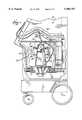
- FIG. 1is a side elevation view, with portions broken away and in section, of a blood processing system comprising a centrifuge with an interface detection system, which embodies features of the invention, the bowl and spool of the centrifuge being shown in their operating position;
- FIG. 2is a side elevation view, with portions broken away and in section, of the centrifuge shown in FIG. 1, with the bowl and spool of the centrifuge shown in their upright position for receiving a blood processing chamber;
- FIG. 3is a top perspective view of the spool of the centrifuge shown in FIG. 2, in its upright position and carrying the blood processing chamber;
- FIG. 4is a plan view of the blood processing chamber shown in FIG. 3, out of association with the spool;
- FIG. 5is an enlarged perspective view of the interface ramp carried by the centrifuge in association with the blood processing chamber, showing the centrifugally separated red blood cell layer, plasma layer, and interface within the chamber when in a desired location on the ramp;
- FIG. 6is an enlarged perspective view of the interface ramp shown in FIG. 5, showing the red blood cell layer and interface at an undesired high location on the ramp;
- FIG. 7is an enlarged perspective view of the interface ramp shown in FIG. 5, showing the red blood cell layer and interface at an undesired low location on the ramp;
- FIG. 8is a side perspective view of the bowl and spool of the centrifuge when in the operating position, showing the viewing head, which forms a part of the interface controller, being carried by the centrifuge to view the interface ramp during rotation of the bowl;
- FIG. 9is a perspective view of the viewing head, with portions broken away and in section, showing the light source and light detector, which are carried by the viewing head, in alignment with the interface ramp, as viewed from within the spool and bowl of the centrifuge;
- FIG. 10is a side section view of the bowl, spool, and viewing head when the viewing head is aligned with the interface ramp;
- FIG. 11is a schematic view of the interface processing element and the interface command element, which form a part of the interface controller;
- FIG. 12is a schematic view of the signal converting element, which forms a part of the interface processing element shown in FIG. 11;
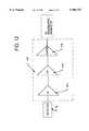
- FIG. 13shows, in its upper portion, a voltage signal generated by the viewing head when passing along the interface ramp and, in its lower portion, a square waveform, which the processing element of the interface controller generates from the voltage signal for the purpose of analyzing the location of the interface on the ramp;
- FIG. 14is a schematic view of the blood calibration element, which forms a part of the interface controller.
- FIGS. 1 and 2show a blood processing system 10, which incorporates an interface controller 12 that embodies features of the invention.
- the inventionis described in the context of blood processing, because it is well suited for use in this environment. Still, it should be appreciated that use of the invention is not limited to blood processing.
- the features of the inventioncan be used in association with any system in which materials that can be optically differentiated are handled.
- the system 10includes a centrifuge 14 used to centrifugally separate blood components.
- the centrifuge 14separates whole blood to harvest red blood cells (RBC), platelet concentrate (PC), and platelet-poor plasma (PPP).
- RBCred blood cells
- PCplatelet concentrate
- PPPplatelet-poor plasma
- the centrifuge 14can also be used to harvest mononuclear cells and granulocytes from blood.
- the centrifuge 14is of the type shown in U.S. Pat. No. 5,316,667, which is incorporated herein by reference.
- the centrifugecomprises a bowl 16 and a spool 18.
- the bowl 16 and spool 18are pivoted on a yoke 20 between an upright position, as FIG. 2 shows, and a suspended position, as FIG. 1 shows.
- the spool 18When upright, the spool 18 can be opened by movement at least partially out of the bowl 16, as FIG. 2 shows. In this position, the operator wraps a flexible blood processing chamber 22 (see FIG. 3) about the spool 18. Closure of the spool 18 and bowl 16 encloses the chamber 22 for processing. When closed, the spool 18 and bowl 16 are pivoted into the suspended position for rotation about an axis.
- the blood processing chamber 22can be variously constructed.
- FIG. 4shows a representative preferred embodiment.
- the chamber 22 shown in FIG. 4provides multi-stage processing.
- a first stage 24separates WB into RBC and platelet-rich plasma (PRP).
- a second stage 26separates the PRP into PC and PPP.
- a port 28conveys WB into the first stage 24.
- Ports 30 and 32respectively, convey PRP and RBC from the first stage 24. RBC is returned to the donor.
- a port 34conveys PRP into the second stage 26.
- a port 36conveys PPP from the second stage 26, leaving PC in the second stage 26 for resuspension and transfer to one or more storage containers.
- the ports 28, 30, 32, 34, and 36are arranged side-by-side along the top transverse edge of the chamber 22.
- a tubing umbilicus 38is attached to the ports 28, 30, 32, 34, and 36.
- the umbilicus 38interconnects the first and second stages 24 and 26 with each other and with pumps and other stationary components located outside the rotating components of the centrifuge 14 (not shown).
- a non-rotating (zero omega) holder 40holds the upper portion of the umbilicus 38 in a non-rotating position above the suspended spool 18 and bowl 16.
- a holder 42 on the yoke 20rotates the mid-portion of the umbilicus 38 at a first (one omega) speed about the suspended spool 18 and bowl 16.
- Another holder 44see FIG.
- a first interior seal 46is located between the PRP collection port 30 and the WB inlet port 28.
- a second interior seal 48is located between the WB inlet port 28 and the RBC collection port 32.
- the interior seals 46 and 48form a WB inlet passage 50 and a PRP collection region 52 in the first stage 24.
- the second seal 48also forms a RBC collection passage 54 in the first stage 24.
- the WB inlet passage 50channels WB directly into the circumferential flow path immediately next to the PRP collection region 52. As shown in FIG. 5, the WB separates into an optically dense layer 56 of RBC, which forms as RBC move under the influence of centrifugal force toward the high-G wall 62. The movement of RBC 56 displaces PRP radially toward the low-G wall 64, forming a second, less optically dense layer 58.
- Centrifugation of WBalso forms an intermediate layer 60, also called the interface, which constitutes the transition between the formed cellular blood components and the liquid plasma component.
- RBCtypically occupy this transition region.
- White blood cellsmay also occupy this transition region.
- Plateletstoo, can leave the PRP layer 58 and settle on the interface 60. This settling action occurs when the radial velocity of the plasma near the interface 60 is not enough to keep the platelets suspended in the PRP layer 58. Lacking sufficient radial flow of plasma, the platelets fall back and settle on the interface 60. Larger platelets (greater than about 30 femtoliters) are particularly subject to settling on the interface 60. However, the closeness of the WB inlet region 50 to the PRP collection region 52 in the chamber 22 shown in FIG. 4 creates strong radial flow of plasma into the PRP collection region 52. The strong radial flow of plasma lifts platelets, large and small, from the interface 60 and into the PRP collection region 52.
- a ramp 66extends from the high-G wall 62 of the bowl 16 at an angle across the PRP collection region 52.
- the angle, measured with respect to the axis of the PRP collection port 30is preferably about 30°.
- FIG. 5shows the orientation of the ramp 66 when viewed from the low-G wall 64 of the spool 18.
- FIG. 4shows, in phantom lines, the orientation of the ramp 66 when viewed from the high-G wall 62 of the bowl 16.
- the ramp 66forms a tapered wedge that restricts the flow of fluid toward the PRP collection port 30.
- the top edge of the ramp 66extends to form a constricted passage 68 along the low-G wall 64. PRP must flow through the constricted passage 68 to reach the PRP collection port 30.
- the ramp 66diverts the fluid flow along the high-G wall 62. This flow diversion changes the orientation of the interface 60 between the RBC layer 56 and the PRP layer 58 within the PRP collection region 52. The ramp 66 thereby displays the RBC layer 56, PRP layer 58, and interface 60 for viewing through the low-G wall 64 of the chamber 22.
- the interface controller 12includes a viewing head 70 (see FIGS. 1 and 8) carried on the yoke 20.
- the viewing head 70is oriented to optically view the transition in optical density between the RBC layer 56 and the PRP layer 58 on the ramp 66.
- the interface controller 12also includes a processing element 72 (see FIGS. 11 and 13), which analyzes the optical data obtained by the viewing head 70 to derive the location of the interface 60 on the ramp 66 relative to the constricted passage 68.
- the location of the interface 60 on the ramp 66can dynamically shift during blood processing, as FIGS. 6 and 7 show.
- the interface controller 12includes a command element 74 (see FIGS. 11 and 13), which varies the rate at which PRP is drawn from the chamber 22 to keep the interface 60 at a prescribed location on the ramp 66 (which FIG. 5 shows).
- Maintaining the interface 60 at a prescribed location on the ramp 66is important. If the location of the interface 60 is too high (that is, if it is too close to the constricted passage 68 leading to the PRP collection port 30, as FIG. 6 shows), RBC, and, if present, white blood cells can spill over and into the constricted passage 68, adversely affecting the quality of PRP. On the other hand, if the location of the interface 60 is too low (that is, if it resides too far away from the constricted passage 68, as FIG. 7 shows), the fluid dynamics advantageous to effective platelet separation can be disrupted. Furthermore, as the distance between the interface 60 and the constricted passage 68 increases, the difficulty of drawing larger platelets into the PRP flow increases. As a result, a distant interface location results in collection of only the smallest platelets, and overall platelet yield will, as a consequence, be poor.
- the viewing head 70carried by the yoke 20, includes a light source 76, which emits light that is absorbed by RBC.
- the light source 76includes a circular array of red light emitting diodes 80. of course, other wavelengths absorbed by RBC, like green or infrared, could be used.
- seven light emitting diodes 80comprise the light source 76. More diodes 80 may be used, or fewer diodes 80 can be used, depending upon the optical characteristics desired.
- the viewing head 70also includes a light detector 78 (see FIGS. 9 and 10), which is mounted adjacent to the light source 76.
- the light detector 78comprises a PIN diode detector, which is located generally in the geometric center of the circular array of light emitting diodes 80.
- the yoke 20 and viewing head 70rotate at a one omega speed, as the spool 18 and bowl 16 rotate at a two omega speed.
- the light source 76directs light onto the rotating bowl 16.
- the bowl 16is transparent to the light emitted by the source 76 only in the region 82 where the bowl 16 overlies the interface ramp 66.
- the region 82comprises a window cut out in the bowl 16.
- the remainder of the bowl 16 that lies in the path of the viewing head 70comprises a light absorbing material.
- the interface ramp 66is made of a light transmissive material. The light from the source 76 will thereby pass through the transparent region 82 of the bowl 16 and the ramp 66 every time the rotating bowl 16 and viewing head 70 align.
- the spool 18may also carry a light reflective material 84 behind the interface ramp 66 to enhance its reflective properties. The spool 18 reflects incoming light received from the source 76 out through the transparent region 82 of the bowl 16, where it is sensed by the detector 78. In the illustrated embodiment, light passing outward from the source 76 and inward toward the detector 78 passes through a focusing lens 120 (shown in FIGS. 9 and 10), which forms a part of the viewing head 70.
- the arrangement just describedoptically differentiates the reflective properties of the interface ramp 66 from the remainder of the bowl 16.
- This objectivecan be achieved in other ways.
- the light source 76could be gated on and off with the arrival and passage of the ramp 66 relative to its line of sight.
- the bowl 16 outside the transparent region 82could carry a material that reflects light, but at a different intensity than the reflective material 84 behind the interface ramp 66.
- the detector 78will first sense light reflected through the plasma layer 58 on the ramp 66. Eventually, the RBC layer 56 adjacent the interface 60 on the ramp 66 will enter the optical path of the viewing head 70. The RBC layer 56 absorbs light from the source 76 and thereby reduces the previously sensed intensity of the reflected light. The intensity of the reflected light sensed by the detector 78 represents the amount of light from the source 76 that is not absorbed by the RBC layer 56 adjacent to the interface 60.
- the interface processing element 72includes a signal converting element 112, which converts the sensed light intensity output of the detector 78 (a current) to an amplified voltage signal.
- the signal converting element 112includes an inverting current to voltage (I/V) amplifier 114, which converts the relatively low positive current signal from the detector 78 (typically, in ⁇ A) to an amplified negative voltage signal.
- the current-to-voltage gain of the amplifier 114can vary. In a representative embodiment, the gain is on the order of 58,000, so that current of, for example, 1 ⁇ A is converted to a voltage signal of -58 mV.
- a non-inverting voltage amplifier (V/V) 116further amplifies the negative voltage signal (in mV) to a negative voltage signal (in V) (i.e., a gain of about 400).
- This twice amplified negative voltage signalis passed through a buffer 118.
- the output of the buffer 118constitutes the output of the signal converting element 112.
- the total amplification factor(from detector current signal to processed negative voltage signal) is about 23 million.
- FIG. 13shows in solid lines a representative curve (designated V1), which plots representative negative voltage outputs of the signal converting element 112 for light signals detected when a light transmissive liquid, e.g., saline, resides along the entire length of the ramp 66.
- the curve V1shows the region 88 where the light signal detected increase, level out, and then decrease, as the transparent region 82 and viewing head 70 pass into and out of alignment.
- the voltage curve V1is negative-going for increasing light signals, due to processing by the signal converting element 112. It should be appreciated that the light signals could be processed to provide a non-inverted voltage output, so that the voltage curve V1 would be positive-going for increasing light signals.
- a waveshaping element 90converts the amplified voltage signals to a square wave time pulse.
- the element 90comprises a voltage comparator, which receives as input the amplified voltage signals and a selected threshold value (THRESH).
- the output of the voltage comparator 88is one (1) when the voltage signal lies below THRESH (that is, when the voltage signal lies further from zero than THRESH) and zero (0) when the voltage signal lies above THRESH (that is, when the voltage signal lies closer to zero than THRESH).
- THRESHcomprises a digital number between 0 and 4095.
- the digital numberis converted by a 12 bit digital-to-analog converter 120 to a voltage analog value between +10 and -10.
- a digital number of zero (0) for THRESHrepresents an analog output of +10 V
- a digital number of 4095 for THRESHrepresents an analog output of -10 V.
- FIG. 13shows in solid lines a representative square wave pulse (designated P1) processed by the comparator 90 from the voltage curve V1, based upon a selected value for THRESH.
- Negative-going voltage curve V1varies from zero (0) (when no light is sensed by the detector 70) to -13.5 V (when maximum light is sensed by the detector 70), and THRESH is the digital number 3481, which the converter 120 converts to an analog voltage value of -7 V.
- the square wave pulse P1has a width (designated W1 in FIG. 13) expressed in terms of time.
- the width W1is proportional to the time that a light signal below THRESH is detected (that is, when the negative voltage signal is farther from zero (0) than analog voltage value of THRESH).
- maximum lightis detected (negative-going voltage signal at -13.5 V) when the interface viewing region 82 and the viewing head 70 align.
- width W1 of the square wave pulse P1is proportional to the entire time period that the interface viewing region 82 and viewing head 70 align. Width W1 will also be called the baseline pulse width, or BASE.
- FIG. 13shows in phantom lines a representative curve (designated V2), which plots representative processed voltage signals detected when RBC occupy about 70% of the length of the ramp 66.
- Negative-going voltage curve V2varies from zero (0) (when no light is sensed by the detector 70) to -9.9 V (when maximum light is sensed by the detector 70).
- the curve V2follows the path of V1 until the detector 78 senses the plasma layer 58, which is not a transmissive to light as saline.
- the maximum sensed signal intensity for plasma(I2 PLASMA ) (for example, -9.9 V) is therefore less than maximum sensed signal intensity for saline (I 1 SALINE) (for example -13.5 volts).
- I 2 PLASMAmaximum sensed signal intensity for plasma
- I 1 SALINEmaximum sensed signal intensity for saline
- the time period during which I2 PLASMA existsis also significantly shorter than the time period which I1 SALINE exists.
- Curve V2shows the gradual decrease in the sensed voltage signal as the light absorbing RBC layer 56 comes progressively into the field of view of the head 70 (which is generally designated I2 RBC in FIG. 13). Curve V2 eventually joins the path of curve V1, as the transparent region 82 and viewing head 70 pass out of alignment.
- FIG. 13also shows in phantom lines that the relative width (W2) of square wave pulse (P2), processed by the comparator 90 using the same THRESH as P1, shortens.
- the width (W2)diminishes in proportion to the width of the RBC layer 56 relative to the width of the plasma layer 58 on the ramp. As the RBC layer 56 occupies more of the ramp 66, i.e., as the RBC-plasma interface 60 moves closer to the constricted passage 68, the pulse width (W2) shortens relative to the baseline pulse width (W1), and vice versa.
- the interface processing element 72assesses the relative physical location of the interface 60 on the ramp 66.
- the interface processing element 72includes calibration modules 92 and 94 to assure that the optically derived physical location of the interface 66 accurately corresponds with the actual physical location of the interface 66.
- the first calibration module 92also called the system calibration module, takes into account the geometry of the spool 18 and ramp 66, as well as operational conditions that can affect the optical acquisition of interface information.
- the second calibration module 94also called the blood calibration module, takes into account the physiology of the donor's blood, in terms of the optical density of his or her plasma.
- the nominal value of the baseline pulse width BASE(expressed in units of time) is selected for a given system.
- a value of, for example, 640 ⁇ seccan be selected for BASE.
- BASE(in microseconds) is converted to a digital count value (COUNTS), as follows: ##EQU1## where SCALE is a selected scale factor (which, in the illustrated embodiment, can be, for example, 80604);
- THRESH ZEROis the digital threshold number that represents an analog threshold voltage output of zero (which, in the illustrated embodiment, is 2048).
- PERIODis the period of rotation of the detector 70, based upon the speed of rotation of the detector 70 (DETECTOR.sub. ⁇ ), calculated as follows: ##EQU2##
- COUNTSneed not be recalculated at different values of DETECTOR.sub. ⁇ , provided BASE is not changed.
- the system calibration module 92derives a square pulse wave P SALINE , like P1 in FIG. 13, by conveying a light transmissive liquid, such as saline, through the chamber 22, while sampling voltage values along the ramp 66.
- the voltage value samplesare processed by the comparator 90 to create the square wave pulse P SALINE , using an estimated initial threshold value THRESH START .
- the width W START of the pulse P SALINE formed using THRESH STARTis measured and compared to the baseline width BASE, which is determined according to Equation (1).
- the system calibration module 92varies the threshold value from THRESH START to vary the pulse width, until the pulse width of P SALINE meets the target criteria for BASE.
- the threshold value that achieves the target baseline pulse width BASEbecomes the default threshold value THRESH DEFAULT for the system.
- sensed pulse widthcan occur during normal use independent of changes in the actual physical dimension of the interface.
- sensed voltage signalscan change due to changes occurring within the viewing head 70, such as loss of focus, deposition of foreign materials on optical surfaces, shifts in optical alignment, or weakening of the light emitting diodes 80 or detector 78.
- Sensed voltage signalswill change due to degradation of optical performance, independent of and unrelated to changes in the physical dimensions of the interface.
- the changed voltage signalscan result in a reduced or enlarged pulse width, which may no longer accurately reflect the actual state of the interface. Erroneous control signals may result.
- the system calibration module 92includes a set up protocol 96.
- the protocol 96sets a threshold value THRESH to obtain the baseline pulse width BASE using actual performance conditions existing at the beginning of each processing cycle.
- the set up protocol 96commands the system to convey saline (or other selected light transmissive material) through the separation chamber 22, as before described in connection with deriving THRESH DEFAULT .
- a representative number of samplese.g., 10 samples
- W DEFAULT (1 to n)are obtained based upon sensed voltage values using THRESH DEFAULT .
- the sample pulse widthsare averaged W DEFAULT (AVG) and compared to BASE for the system, derived according to Equation (1). If W DEFAULT (AVG) equals BASE, or, alternatively, lies within an acceptable range of values for BASE, THRESH is set at THRESH DEFAULT .
- the protocol 96uses the following criteria is used to evaluate THRESH DEFAULT :
- BASE UPPERis a selected maximum value for the baseline pulse width, e.g., BASE times a selected multiplier greater than 1.0, for example 1.0025;
- BASE LOWERis a selected minimum value for the baseline pulse width, e.g., BASE times a selected multiplier less than 1.0, for example 0.9975.
- the set up proceduresearches for a value for THRESH that brings W DEFAULT (AVG) into compliance with the established criteria for BASE.
- Various search algorithmscan be used for this purpose.
- the set up procedurecan use a half-step search algorithm, as follows:
- THRESHis the name given to the interface threshold value selected;
- THRESH UPPERis a set maximum value for THRESH;
- THRESH LOWERis a set minimum value for THRESH; and
- W SAMPLE (AVG)is an average of pulse widths taken during a set sample period.
- THRESH n(THRESH LOWER +THRESH UPPER )/2
- THRESH n(THRESH UPPER +THRESH LOWER )/2
- the system calibration module 92thereby assures that the optically derived location of the interface 66 is not skewed based upon operational conditions that can affect the optical acquisition of interface information.
- the interface controller 12can operate on the premise the optical density of the donor's plasma residing on the ramp 66 is substantially equivalent to the optical density of the material (e.g., saline) used by the system calibration module 92 at the outset of a given procedure.
- the optical density of normal plasmacan be considered equivalent to saline.
- plasma particularly rich in plateletswhich is a processing goal of the system 10
- plasma particularly rich in plateletswhich is a processing goal of the system 10
- the optical density of plasmawill also vary according to the concentration of lipids in the plasma, which depends upon the physiology or morphology of the individual donor. Lipemic plasma has a density that differs significantly from saline or non-lipemic plasma.
- the associated square wave pulsespossess a reduced pulse width.
- the reduced pulse widthis caused by the physiology of the donor's blood, and does not accurately reflect the actual state of the interface.
- a RBC-plasma interface 60 located at the proper position on the ramp 66will, in the presence of lipemic plasma or very platelet rich plasma, generate a pulse width, which is otherwise indicative for normal plasma of an RBC-plasma interface 60 that is too close.
- the artificially reduced pulse widthwill generate an error signal, which commands a reduction in the rate at which plasma is conveyed through the port 34.
- the previously properly positioned interface 60is needlessly shifted to an out-of-position location down the ramp 66.
- the second calibration module 94adjusts the pulse width in the presence of plasma having an optical density significantly different than saline, to reflect the true position of the interface and thereby avoid blood-related optical distortions.
- the module 94includes an optical monitor 98 (see FIG. 14), which senses the optical density of plasma exiting the plasma outlet port 30 or entering the PRP inlet port 34.
- the optical monitor 98is a conventional hemoglobin detector, used on the Autopheresis-C® blood processing device sold by the Fenwal Division of Baxter Healthcare Corporation.
- the monitor 98comprises a red light emitting diode 102, which emits light into the plasma outlet tubing 104.
- the monitor 98also includes a PIN diode detector 106 on the opposite side of the tubing 104.
- Using the essentially the same wavelength for monitoring the interface and monitoring plasmais a preferred implementation. Using essentially the same wavelengths makes the absorbance spectrum for plasma essentially the same for both detectors. Therefore, there is no need to correlate the absorbance spectrum of the interface detector to the absorbance spectrum of the plasma detector. Of course, different wavelengths can be used, if desired, in which case the absorbance spectrums for plasma of the different wavelengths should be correlated, to achieve accurate calibration results.
- the second calibration module 94also includes a processing element 100, which receives signals from the monitor 98 to compute the optical transmission of the liquid conveyed through the tubing 104, which is called OPTTRANS.
- OPTTRANSvarious algorithms can be used by the processing element 100 to compute OPTTRANS.
- OPTTRANSis derived, as follows: ##EQU3## where COR(RED SPILL) is calculated as follows:
- REDis the output of the diode detector when the red light emitting diode is on and the liquid flows through the tubing;
- REDBKGRDis the output of the diode detector when the red light emitting diode is off and the liquid flows through the tubing;
- REFis the output of the red light emitting diode when the diode is on.
- REFBKGRDis the output of the red light emitting diode when the diode is off.
- the processing element 100obtains data from the monitor 98 and derives the optical transmission of the tubing and the light transmissive, set up liquid, such as saline.
- optical transmission valuesare calculated at the fastest possible rate during the set up procedure. The values are averaged over the entire set up procedure to derive an optical transmission value for the tubing and setup liquid (OPTTRANS SETUP ).
- optical transmission valuesare calculated by the processing element 100 at the fastest possible rate during the blood processing procedure. The values are periodically averaged at the end of a set sampling interval (for example, every 180 seconds) to derive an optical transmission value for the tubing and plasma (OPTTRANS PLASMA ).
- the processing module 100determines a new threshold value THRESH, for deriving the pulse width, which varies as a function of OPTRANS, as follows: ##EQU4## where MULT is a predetermined scale factor from 0 to, for example, 1000. In the illustrated embodiment, MULT can be set at 200.
- the foregoing correction of THRESHincreases the pulse width in relation to increases in optical density of plasma on the ramp 66.
- the second calibration module 94thereby takes into account diminution in voltage signal gain in the presence on the ramp 66 of lipemic plasma or plasma with very high platelet counts.
- the second calibration module 94thereby serves as a gain controller for the interface controller 12, adjusting the width of the pulse to accurately reflect the actual physical location of the interface on the ramp, despite the presence of plasma having greater than normal optical density.
- the foregoing descriptionshows the processing element 72 receiving sensed light intensity values from an interface detector 70 that senses light reflected from the interface ramp 66. It should be appreciated that comparable light intensity values can be obtained for processing by the processing element 72 from an interface detector that senses light after transmission through the interface ramp 66, without back reflection.
- a light sourceis carried by the yoke 20 (in the same manner as the optical head 70), and a light detector is carried by the spool 18 behind the interface ramp 66, or vice versa.
- the interface command element 74receives as input the interface location output of the processing element 72.
- the command elementincludes a comparator 108, which compares the interface location output with a desired interface location to generate an error signal (E).
- Eerror signal
- the desired interface locationis expressed as a control value consistent with the expression of the interface dimension output.
- RBCshould occupy no more than about 60% to 65% of the ramp 66.
- Thiscan conversely be expressed in terms of a control value (expressed as a percentage) of between 35% to 40% of BASE, meaning that the measured pulse width W should be 35% to 40% of its maximum value.
- the control valuecan be expressed in terms of a number representing a pulse width value (in time units) integrated to a voltage value proportional to the percentage of plasma occupying the ramp 66.
- control valuescan be used depending upon the particular blood component collection objectives.
- a positive error signal (+E)indicates that the RBC layer 56 on the ramp 66 is too large (as FIG. 6 shows).
- the interface command element 74generates a signal to reduce the rate which PRP is removed through port 34.
- the interface 60moves away from the constricted passage 68 toward the desired control position (as FIG. 5 shows), where the error signal (E) is zero.
- a negative error signal (-E)indicates that the RBC layer 56 on the ramp 66 is too small (as FIG. 7 shows).
- the interface command element 74generates a signal to increase the rate at which PRP is removed through the port 34.
- the interface 60moves toward the constricted passage 68 toward the desired control position (FIG. 5), where the error signal (E) is again zero.
- the interface command element 74can affect the rate at which plasma is removed through the port 34 by controlling the relative flow rates of WB, the RBC, and the PRP through their respective ports.
- a pump 110draws PRP via the tubing 104 through the port 34.
- the command element 74controls the pump rate of the pump 110 to keep the interface 60 at the prescribed location on the ramp 66, away from the constricted passage 68.
Landscapes
- Physics & Mathematics (AREA)
- Electromagnetism (AREA)
- Thermal Sciences (AREA)
- Fluid Mechanics (AREA)
- General Physics & Mathematics (AREA)
- Chemical & Material Sciences (AREA)
- Chemical Kinetics & Catalysis (AREA)
- External Artificial Organs (AREA)
Abstract
Description
COR(RED SPILL)=RED-REDKGRD
CORREF=REF-REBKGRD
Claims (17)
Priority Applications (1)
| Application Number | Priority Date | Filing Date | Title |
|---|---|---|---|
| US08/922,880US5980757A (en) | 1997-04-03 | 1997-09-03 | Interface detection and control systems and method |
Applications Claiming Priority (2)
| Application Number | Priority Date | Filing Date | Title |
|---|---|---|---|
| PCT/US1997/005829WO1998043720A1 (en) | 1997-04-03 | 1997-04-03 | Interface detection and control systems and methods |
| US08/922,880US5980757A (en) | 1997-04-03 | 1997-09-03 | Interface detection and control systems and method |
Related Parent Applications (1)
| Application Number | Title | Priority Date | Filing Date |
|---|---|---|---|
| PCT/US1997/005829ContinuationWO1998043720A1 (en) | 1997-04-03 | 1997-04-03 | Interface detection and control systems and methods |
Publications (1)
| Publication Number | Publication Date |
|---|---|
| US5980757Atrue US5980757A (en) | 1999-11-09 |
Family
ID=22260680
Family Applications (1)
| Application Number | Title | Priority Date | Filing Date |
|---|---|---|---|
| US08/922,880Expired - LifetimeUS5980757A (en) | 1997-04-03 | 1997-09-03 | Interface detection and control systems and method |
Country Status (2)
| Country | Link |
|---|---|
| US (1) | US5980757A (en) |
| WO (1) | WO1998043720A1 (en) |
Cited By (55)
| Publication number | Priority date | Publication date | Assignee | Title |
|---|---|---|---|---|
| US6183651B1 (en)* | 1997-07-18 | 2001-02-06 | Baxter International Inc. | Blood processing systems and methods which optically monitor plasma opacity |
| US6254784B1 (en)* | 1997-10-30 | 2001-07-03 | Baxter International Inc. | Optical interface detection system for centrifugal blood processing |
| US6312607B1 (en) | 1995-06-07 | 2001-11-06 | Baxter International Inc. | Blood processing systems and methods which optically monitor incremental platelet volumes in a plasma constituent |
| US6315707B1 (en) | 1999-09-03 | 2001-11-13 | Baxter International Inc. | Systems and methods for seperating blood in a rotating field |
| US6322488B1 (en) | 1999-09-03 | 2001-11-27 | Baxter International Inc. | Blood separation chamber with preformed blood flow passages and centralized connection to external tubing |
| US20020077241A1 (en)* | 1999-09-03 | 2002-06-20 | Baxter International Inc. | Blood processing systems and methods with quick attachment of a blood separation chamber to a centrifuge rotor |
| US6524231B1 (en) | 1999-09-03 | 2003-02-25 | Baxter International Inc. | Blood separation chamber with constricted interior channel and recessed passage |
| US20030181305A1 (en)* | 2002-03-04 | 2003-09-25 | Briggs Dennis A. | Method and apparatus for the continuous separation of biological fluids into components |
| US20040082459A1 (en)* | 2002-10-24 | 2004-04-29 | Baxter International Inc. | Blood processing systems and methods for collecting plasma free or essentially free of cellular blood components |
| US20040082458A1 (en)* | 1999-09-03 | 2004-04-29 | Baxter International Inc. | Blood processing systems and methods with umbilicus-driven blood processing chambers |
| US20050054508A1 (en)* | 2003-09-05 | 2005-03-10 | Ivo Panzani | Control device for the separate collection of blood components in output from a blood centrifugation cell |
| US6890291B2 (en) | 2001-06-25 | 2005-05-10 | Mission Medical, Inc. | Integrated automatic blood collection and processing unit |
| US20060021952A1 (en)* | 2003-09-11 | 2006-02-02 | Skinkle David W | Apparatus for separating blood components |
| US7037428B1 (en) | 2002-04-19 | 2006-05-02 | Mission Medical, Inc. | Integrated automatic blood processing unit |
| US7211037B2 (en) | 2002-03-04 | 2007-05-01 | Therakos, Inc. | Apparatus for the continuous separation of biological fluids into components and method of using same |
| US7297272B2 (en) | 2002-10-24 | 2007-11-20 | Fenwal, Inc. | Separation apparatus and method |
| US20080041772A1 (en)* | 2006-08-17 | 2008-02-21 | Gambro Bct, Inc. | Blood Processing Apparatus with Robust Outflow Process Control |
| WO2008021633A3 (en)* | 2006-08-17 | 2008-05-02 | Gambro Bct Inc | Blood processing apparatus with robust outflow process control |
| US7476209B2 (en) | 2004-12-21 | 2009-01-13 | Therakos, Inc. | Method and apparatus for collecting a blood component and performing a photopheresis treatment |
| US7479123B2 (en) | 2002-03-04 | 2009-01-20 | Therakos, Inc. | Method for collecting a desired blood component and performing a photopheresis treatment |
| US7708152B2 (en) | 2005-02-07 | 2010-05-04 | Hanuman Llc | Method and apparatus for preparing platelet rich plasma and concentrates thereof |
| US7824559B2 (en) | 2005-02-07 | 2010-11-02 | Hanumann, LLC | Apparatus and method for preparing platelet rich plasma and concentrates thereof |
| US7866485B2 (en) | 2005-02-07 | 2011-01-11 | Hanuman, Llc | Apparatus and method for preparing platelet rich plasma and concentrates thereof |
| US8012077B2 (en) | 2008-05-23 | 2011-09-06 | Biomet Biologics, Llc | Blood separating device |
| US8187475B2 (en) | 2009-03-06 | 2012-05-29 | Biomet Biologics, Llc | Method and apparatus for producing autologous thrombin |
| US8337711B2 (en) | 2008-02-29 | 2012-12-25 | Biomet Biologics, Llc | System and process for separating a material |
| US20140033864A1 (en)* | 2011-09-22 | 2014-02-06 | Fenwal, Inc. | Drive system for centrifuge |
| US8808551B2 (en) | 2002-05-24 | 2014-08-19 | Biomet Biologics, Llc | Apparatus and method for separating and concentrating fluids containing multiple components |
| US8950586B2 (en) | 2002-05-03 | 2015-02-10 | Hanuman Llc | Methods and apparatus for isolating platelets from blood |
| US8992862B2 (en) | 2009-04-03 | 2015-03-31 | Biomet Biologics, Llc | All-in-one means of separating blood components |
| US9011800B2 (en) | 2009-07-16 | 2015-04-21 | Biomet Biologics, Llc | Method and apparatus for separating biological materials |
| US9114334B2 (en) | 2002-05-24 | 2015-08-25 | Biomet Biologics, Llc | Apparatus and method for separating and concentrating fluids containing multiple components |
| US9138664B2 (en) | 2007-04-12 | 2015-09-22 | Biomet Biologics, Llc | Buoy fractionation system |
| US9239276B2 (en) | 2011-04-19 | 2016-01-19 | Biomet Biologics, Llc | Apparatus and method for separating and concentrating fluids containing multiple components |
| US9334927B2 (en)* | 2011-09-22 | 2016-05-10 | Fenwal, Inc. | Drive system for centrifuge with planetary gear and flexible shaft |
| US9533090B2 (en) | 2010-04-12 | 2017-01-03 | Biomet Biologics, Llc | Method and apparatus for separating a material |
| US9556243B2 (en) | 2013-03-15 | 2017-01-31 | Biomet Biologies, LLC | Methods for making cytokine compositions from tissues using non-centrifugal methods |
| US9594020B2 (en) | 2012-09-04 | 2017-03-14 | Fenwal, Inc. | Interface detector for blood processing system |
| US9642956B2 (en) | 2012-08-27 | 2017-05-09 | Biomet Biologics, Llc | Apparatus and method for separating and concentrating fluids containing multiple components |
| US9649579B2 (en) | 2007-04-12 | 2017-05-16 | Hanuman Llc | Buoy suspension fractionation system |
| US9701728B2 (en) | 2008-02-27 | 2017-07-11 | Biomet Biologics, Llc | Methods and compositions for delivering interleukin-1 receptor antagonist |
| US9713810B2 (en) | 2015-03-30 | 2017-07-25 | Biomet Biologics, Llc | Cell washing plunger using centrifugal force |
| US9757721B2 (en) | 2015-05-11 | 2017-09-12 | Biomet Biologics, Llc | Cell washing plunger using centrifugal force |
| EP3254713A1 (en) | 2016-06-08 | 2017-12-13 | Fenwal, Inc. | Systems for therapeutic platelet depletion |
| US9895418B2 (en) | 2013-03-15 | 2018-02-20 | Biomet Biologics, Llc | Treatment of peripheral vascular disease using protein solutions |
| US9897589B2 (en) | 2002-05-24 | 2018-02-20 | Biomet Biologics, Llc | Apparatus and method for separating and concentrating fluids containing multiple components |
| US9950035B2 (en) | 2013-03-15 | 2018-04-24 | Biomet Biologics, Llc | Methods and non-immunogenic compositions for treating inflammatory disorders |
| US10143725B2 (en) | 2013-03-15 | 2018-12-04 | Biomet Biologics, Llc | Treatment of pain using protein solutions |
| US10166322B2 (en) | 2014-03-28 | 2019-01-01 | Terumo Bct, Inc. | Gain in separation processes with control loop |
| WO2019140491A1 (en) | 2018-01-22 | 2019-07-25 | Scinogy Products Pty Ltd | System, method and controller for recovery of concentrated particles suspended in fluid |
| US10561784B2 (en) | 2017-05-31 | 2020-02-18 | Fenwal, Inc. | Stationary optical monitoring system for blood processing system |
| US10576130B2 (en) | 2013-03-15 | 2020-03-03 | Biomet Manufacturing, Llc | Treatment of collagen defects using protein solutions |
| EP3741460A1 (en)* | 2019-05-23 | 2020-11-25 | Fenwal, Inc. | Adjustment of target interface location between separated fluid components in a centrifuge |
| US11898967B2 (en) | 2021-02-02 | 2024-02-13 | Fenwal, Inc. | Predicting malfunction and failure of centrifuge umbilicus |
| US12313441B2 (en) | 2021-01-29 | 2025-05-27 | Fenwal, Inc. | Automated splitting of a fluid into uneven volumes |
Families Citing this family (1)
| Publication number | Priority date | Publication date | Assignee | Title |
|---|---|---|---|---|
| US20230218814A1 (en)* | 2022-01-11 | 2023-07-13 | Fenwal, Inc. | Adjustment Of Target Interface Position In A Centrifuge Based On Lipid Concentration |
Citations (23)
| Publication number | Priority date | Publication date | Assignee | Title |
|---|---|---|---|---|
| US3727066A (en)* | 1968-02-16 | 1973-04-10 | Baxter Laboratories Inc | Probe photometer with fluid sensing device |
| US3752995A (en)* | 1972-04-07 | 1973-08-14 | Coulter Electronics | Blank value storing photometer |
| US4468219A (en)* | 1983-12-20 | 1984-08-28 | International Business Machines Corporation | Pump flow rate compensation system |
| US4810090A (en)* | 1987-08-24 | 1989-03-07 | Cobe Laboratories, Inc. | Method and apparatus for monitoring blood components |
| US4828716A (en)* | 1987-04-03 | 1989-05-09 | Andronic Devices, Ltd. | Apparatus and method for separating phases of blood |
| US5104526A (en)* | 1987-01-30 | 1992-04-14 | Baxter International Inc. | Centrifugation system having an interface detection system |
| US5316667A (en)* | 1989-05-26 | 1994-05-31 | Baxter International Inc. | Time based interface detection systems for blood processing apparatus |
| US5316666A (en)* | 1987-01-30 | 1994-05-31 | Baxter International Inc. | Blood processing systems with improved data transfer between stationary and rotating elements |
| US5437598A (en)* | 1994-01-21 | 1995-08-01 | Cobe Laboratories, Inc. | Automation of plasma sequestration |
| US5478479A (en)* | 1994-05-20 | 1995-12-26 | Haemonetics Corporation | Two-stage cell wash process controlled by optical sensor |
| US5494592A (en)* | 1993-04-27 | 1996-02-27 | Haemonetics Corporation | Apheresis apparatus and method |
| US5496265A (en)* | 1992-03-04 | 1996-03-05 | Cobe Laboratories, Inc. | Blood component collection system with optimizer |
| US5573678A (en)* | 1987-01-30 | 1996-11-12 | Baxter International Inc. | Blood processing systems and methods for collecting mono nuclear cells |
| US5605842A (en)* | 1992-07-10 | 1997-02-25 | Cobe Laboratories, Inc. | Method for producing blood component products |
| US5637082A (en)* | 1996-02-22 | 1997-06-10 | Haemonetics Corporation | Adaptive apheresis apparatus |
| US5639382A (en)* | 1991-12-23 | 1997-06-17 | Baxter International Inc. | Systems and methods for deriving recommended storage parameters for collected blood components |
| US5656163A (en)* | 1987-01-30 | 1997-08-12 | Baxter International Inc. | Chamber for use in a rotating field to separate blood components |
| US5658240A (en)* | 1992-03-04 | 1997-08-19 | Cobe Laboratories, Inc. | Blood component collection system with optimizer |
| US5681273A (en)* | 1991-12-23 | 1997-10-28 | Baxter International Inc. | Systems and methods for predicting blood processing parameters |
| US5730883A (en)* | 1991-12-23 | 1998-03-24 | Baxter International Inc. | Blood processing systems and methods using apparent hematocrit as a process control parameter |
| US5769811A (en)* | 1995-10-31 | 1998-06-23 | Haemonetics Corporation | Blood-processing machine system |
| US5792372A (en)* | 1987-01-30 | 1998-08-11 | Baxter International, Inc. | Enhanced yield collection systems and methods for obtaining concentrated platelets from platelet-rich plasma |
| US5827746A (en)* | 1995-03-15 | 1998-10-27 | Sire Analytical Systems Srl | Method to determine the sedimentation of blood and relative device |
- 1997
- 1997-04-03WOPCT/US1997/005829patent/WO1998043720A1/enactiveApplication Filing
- 1997-09-03USUS08/922,880patent/US5980757A/ennot_activeExpired - Lifetime
Patent Citations (24)
| Publication number | Priority date | Publication date | Assignee | Title |
|---|---|---|---|---|
| US3727066A (en)* | 1968-02-16 | 1973-04-10 | Baxter Laboratories Inc | Probe photometer with fluid sensing device |
| US3752995A (en)* | 1972-04-07 | 1973-08-14 | Coulter Electronics | Blank value storing photometer |
| US4468219A (en)* | 1983-12-20 | 1984-08-28 | International Business Machines Corporation | Pump flow rate compensation system |
| US5573678A (en)* | 1987-01-30 | 1996-11-12 | Baxter International Inc. | Blood processing systems and methods for collecting mono nuclear cells |
| US5104526A (en)* | 1987-01-30 | 1992-04-14 | Baxter International Inc. | Centrifugation system having an interface detection system |
| US5316666A (en)* | 1987-01-30 | 1994-05-31 | Baxter International Inc. | Blood processing systems with improved data transfer between stationary and rotating elements |
| US5792372A (en)* | 1987-01-30 | 1998-08-11 | Baxter International, Inc. | Enhanced yield collection systems and methods for obtaining concentrated platelets from platelet-rich plasma |
| US5656163A (en)* | 1987-01-30 | 1997-08-12 | Baxter International Inc. | Chamber for use in a rotating field to separate blood components |
| US4828716A (en)* | 1987-04-03 | 1989-05-09 | Andronic Devices, Ltd. | Apparatus and method for separating phases of blood |
| US4810090A (en)* | 1987-08-24 | 1989-03-07 | Cobe Laboratories, Inc. | Method and apparatus for monitoring blood components |
| US5316667A (en)* | 1989-05-26 | 1994-05-31 | Baxter International Inc. | Time based interface detection systems for blood processing apparatus |
| US5639382A (en)* | 1991-12-23 | 1997-06-17 | Baxter International Inc. | Systems and methods for deriving recommended storage parameters for collected blood components |
| US5730883A (en)* | 1991-12-23 | 1998-03-24 | Baxter International Inc. | Blood processing systems and methods using apparent hematocrit as a process control parameter |
| US5681273A (en)* | 1991-12-23 | 1997-10-28 | Baxter International Inc. | Systems and methods for predicting blood processing parameters |
| US5496265A (en)* | 1992-03-04 | 1996-03-05 | Cobe Laboratories, Inc. | Blood component collection system with optimizer |
| US5658240A (en)* | 1992-03-04 | 1997-08-19 | Cobe Laboratories, Inc. | Blood component collection system with optimizer |
| US5611997A (en)* | 1992-07-10 | 1997-03-18 | Cobe Laboratories, Inc. | Apparatus for producing blood component products |
| US5605842A (en)* | 1992-07-10 | 1997-02-25 | Cobe Laboratories, Inc. | Method for producing blood component products |
| US5494592A (en)* | 1993-04-27 | 1996-02-27 | Haemonetics Corporation | Apheresis apparatus and method |
| US5437598A (en)* | 1994-01-21 | 1995-08-01 | Cobe Laboratories, Inc. | Automation of plasma sequestration |
| US5478479A (en)* | 1994-05-20 | 1995-12-26 | Haemonetics Corporation | Two-stage cell wash process controlled by optical sensor |
| US5827746A (en)* | 1995-03-15 | 1998-10-27 | Sire Analytical Systems Srl | Method to determine the sedimentation of blood and relative device |
| US5769811A (en)* | 1995-10-31 | 1998-06-23 | Haemonetics Corporation | Blood-processing machine system |
| US5637082A (en)* | 1996-02-22 | 1997-06-10 | Haemonetics Corporation | Adaptive apheresis apparatus |
Non-Patent Citations (4)
| Title |
|---|
| Dumont et al., Enhanced Flow Cytometric Method of Counting Very Low Numbers of White Cells in Platelet Products, Cytometry, 26:311 318(1996).* |
| Dumont et al., Enhanced Flow Cytometric Method of Counting Very Low Numbers of White Cells in Platelet Products, Cytometry, 26:311-318(1996). |
| Liles et al. A comparative trial of granulocyte colony stimulating factor and dexamethasone, separately and in combination for the mobilzation of neutrophils in the peripheral blood of normal volunteers, Transfusion, vol. 37, Mar. 1997.* |
| Liles et al. A comparative trial of granulocyte-colony-stimulating factor and dexamethasone, separately and in combination for the mobilzation of neutrophils in the peripheral blood of normal volunteers, Transfusion, vol. 37, Mar. 1997. |
Cited By (98)
| Publication number | Priority date | Publication date | Assignee | Title |
|---|---|---|---|---|
| US6312607B1 (en) | 1995-06-07 | 2001-11-06 | Baxter International Inc. | Blood processing systems and methods which optically monitor incremental platelet volumes in a plasma constituent |
| US6183651B1 (en)* | 1997-07-18 | 2001-02-06 | Baxter International Inc. | Blood processing systems and methods which optically monitor plasma opacity |
| US6254784B1 (en)* | 1997-10-30 | 2001-07-03 | Baxter International Inc. | Optical interface detection system for centrifugal blood processing |
| US20030203802A1 (en)* | 1999-09-03 | 2003-10-30 | Baxter International Inc. | Blood separation chamber with preformed blood flow passages and centralized connection to external tubing |
| US6322488B1 (en) | 1999-09-03 | 2001-11-27 | Baxter International Inc. | Blood separation chamber with preformed blood flow passages and centralized connection to external tubing |
| US20020077241A1 (en)* | 1999-09-03 | 2002-06-20 | Baxter International Inc. | Blood processing systems and methods with quick attachment of a blood separation chamber to a centrifuge rotor |
| US6524231B1 (en) | 1999-09-03 | 2003-02-25 | Baxter International Inc. | Blood separation chamber with constricted interior channel and recessed passage |
| US7166231B2 (en) | 1999-09-03 | 2007-01-23 | Baxter International Inc. | Red blood cell separation method |
| US20040082458A1 (en)* | 1999-09-03 | 2004-04-29 | Baxter International Inc. | Blood processing systems and methods with umbilicus-driven blood processing chambers |
| US6800054B2 (en) | 1999-09-03 | 2004-10-05 | Baxter International Inc. | Blood separation chamber with preformed blood flow passages and centralized connection to external tubing |
| US7789245B2 (en) | 1999-09-03 | 2010-09-07 | Fenwal, Inc. | Blood separation chamber |
| US6860846B2 (en) | 1999-09-03 | 2005-03-01 | Baxter International Inc. | Blood processing systems and methods with umbilicus-driven blood processing chambers |
| US6315707B1 (en) | 1999-09-03 | 2001-11-13 | Baxter International Inc. | Systems and methods for seperating blood in a rotating field |
| US7695423B2 (en) | 2001-06-25 | 2010-04-13 | Terumo Medical Corporation | Method of simultaneous blood collection and separation using a continuous flow centrifuge having a separation channel |
| US7115205B2 (en) | 2001-06-25 | 2006-10-03 | Mission Medical, Inc. | Method of simultaneous blood collection and separation using a continuous flow centrifuge having a separation channel |
| US6890291B2 (en) | 2001-06-25 | 2005-05-10 | Mission Medical, Inc. | Integrated automatic blood collection and processing unit |
| US10556055B2 (en) | 2002-03-04 | 2020-02-11 | Mallinckrodt Hospital Products IP Limited | Method for collecting a desired blood component and performing a photopheresis treatment |
| US9238097B2 (en) | 2002-03-04 | 2016-01-19 | Therakos, Inc. | Method for collecting a desired blood component and performing a photopheresis treatment |
| US7850634B2 (en) | 2002-03-04 | 2010-12-14 | Therakos, Inc. | Method for collecting a desired blood component and performing a photopheresis treatment |
| US20030181305A1 (en)* | 2002-03-04 | 2003-09-25 | Briggs Dennis A. | Method and apparatus for the continuous separation of biological fluids into components |
| US7186230B2 (en) | 2002-03-04 | 2007-03-06 | Therakos, Inc | Method and apparatus for the continuous separation of biological fluids into components |
| US7211037B2 (en) | 2002-03-04 | 2007-05-01 | Therakos, Inc. | Apparatus for the continuous separation of biological fluids into components and method of using same |
| US7503889B2 (en) | 2002-03-04 | 2009-03-17 | Dennis Briggs | Apparatus for the continuous separation of biological fluids into components and method of using same |
| US7479123B2 (en) | 2002-03-04 | 2009-01-20 | Therakos, Inc. | Method for collecting a desired blood component and performing a photopheresis treatment |
| US7914477B2 (en) | 2002-03-04 | 2011-03-29 | Therakos, Inc. | Apparatus for the continuous separation of biological fluids into components and method of using same |
| US7037428B1 (en) | 2002-04-19 | 2006-05-02 | Mission Medical, Inc. | Integrated automatic blood processing unit |
| US7531098B2 (en) | 2002-04-19 | 2009-05-12 | Terumo Medical Corporation | Integrated automatic blood processing unit |
| US8950586B2 (en) | 2002-05-03 | 2015-02-10 | Hanuman Llc | Methods and apparatus for isolating platelets from blood |
| US8808551B2 (en) | 2002-05-24 | 2014-08-19 | Biomet Biologics, Llc | Apparatus and method for separating and concentrating fluids containing multiple components |
| US10393728B2 (en) | 2002-05-24 | 2019-08-27 | Biomet Biologics, Llc | Apparatus and method for separating and concentrating fluids containing multiple components |
| US9114334B2 (en) | 2002-05-24 | 2015-08-25 | Biomet Biologics, Llc | Apparatus and method for separating and concentrating fluids containing multiple components |
| US10183042B2 (en) | 2002-05-24 | 2019-01-22 | Biomet Manufacturing, Llc | Apparatus and method for separating and concentrating fluids containing multiple components |
| US9897589B2 (en) | 2002-05-24 | 2018-02-20 | Biomet Biologics, Llc | Apparatus and method for separating and concentrating fluids containing multiple components |
| US7297272B2 (en) | 2002-10-24 | 2007-11-20 | Fenwal, Inc. | Separation apparatus and method |
| US6849039B2 (en) | 2002-10-24 | 2005-02-01 | Baxter International Inc. | Blood processing systems and methods for collecting plasma free or essentially free of cellular blood components |
| US7918350B2 (en) | 2002-10-24 | 2011-04-05 | Fenwal, Inc. | Separation apparatus and method |
| US20040082459A1 (en)* | 2002-10-24 | 2004-04-29 | Baxter International Inc. | Blood processing systems and methods for collecting plasma free or essentially free of cellular blood components |
| US20050054508A1 (en)* | 2003-09-05 | 2005-03-10 | Ivo Panzani | Control device for the separate collection of blood components in output from a blood centrifugation cell |
| US7311849B2 (en) | 2003-09-05 | 2007-12-25 | Sorin Group Italia S.R.L. | Control device for the separate collection of blood components in output from a blood centrifugation cell |
| US20060021952A1 (en)* | 2003-09-11 | 2006-02-02 | Skinkle David W | Apparatus for separating blood components |
| US7060018B2 (en) | 2003-09-11 | 2006-06-13 | Cobe Cardiovascular, Inc. | Centrifuge apparatus for processing blood |
| US7407472B2 (en) | 2003-09-11 | 2008-08-05 | Sorin Group Usa, Inc. | Centrifuge apparatus for processing blood |
| US7476209B2 (en) | 2004-12-21 | 2009-01-13 | Therakos, Inc. | Method and apparatus for collecting a blood component and performing a photopheresis treatment |
| US8105495B2 (en) | 2005-02-07 | 2012-01-31 | Hanuman, Llc | Method for preparing platelet rich plasma and concentrates thereof |
| US7987995B2 (en) | 2005-02-07 | 2011-08-02 | Hanuman, Llc | Method and apparatus for preparing platelet rich plasma and concentrates thereof |
| US7824559B2 (en) | 2005-02-07 | 2010-11-02 | Hanumann, LLC | Apparatus and method for preparing platelet rich plasma and concentrates thereof |
| US8133389B2 (en) | 2005-02-07 | 2012-03-13 | Hanuman, Llc | Method and apparatus for preparing platelet rich plasma and concentrates thereof |
| US7708152B2 (en) | 2005-02-07 | 2010-05-04 | Hanuman Llc | Method and apparatus for preparing platelet rich plasma and concentrates thereof |
| US7866485B2 (en) | 2005-02-07 | 2011-01-11 | Hanuman, Llc | Apparatus and method for preparing platelet rich plasma and concentrates thereof |
| US8096422B2 (en) | 2005-02-07 | 2012-01-17 | Hanuman Llc | Apparatus and method for preparing platelet rich plasma and concentrates thereof |
| WO2008021633A3 (en)* | 2006-08-17 | 2008-05-02 | Gambro Bct Inc | Blood processing apparatus with robust outflow process control |
| US20080041772A1 (en)* | 2006-08-17 | 2008-02-21 | Gambro Bct, Inc. | Blood Processing Apparatus with Robust Outflow Process Control |
| US9138664B2 (en) | 2007-04-12 | 2015-09-22 | Biomet Biologics, Llc | Buoy fractionation system |
| US9649579B2 (en) | 2007-04-12 | 2017-05-16 | Hanuman Llc | Buoy suspension fractionation system |
| US10400017B2 (en) | 2008-02-27 | 2019-09-03 | Biomet Biologics, Llc | Methods and compositions for delivering interleukin-1 receptor antagonist |
| US11725031B2 (en) | 2008-02-27 | 2023-08-15 | Biomet Manufacturing, Llc | Methods and compositions for delivering interleukin-1 receptor antagonist |
| US9701728B2 (en) | 2008-02-27 | 2017-07-11 | Biomet Biologics, Llc | Methods and compositions for delivering interleukin-1 receptor antagonist |
| US8801586B2 (en)* | 2008-02-29 | 2014-08-12 | Biomet Biologics, Llc | System and process for separating a material |
| US8337711B2 (en) | 2008-02-29 | 2012-12-25 | Biomet Biologics, Llc | System and process for separating a material |
| US9719063B2 (en) | 2008-02-29 | 2017-08-01 | Biomet Biologics, Llc | System and process for separating a material |
| US8012077B2 (en) | 2008-05-23 | 2011-09-06 | Biomet Biologics, Llc | Blood separating device |
| US8783470B2 (en) | 2009-03-06 | 2014-07-22 | Biomet Biologics, Llc | Method and apparatus for producing autologous thrombin |
| US8187475B2 (en) | 2009-03-06 | 2012-05-29 | Biomet Biologics, Llc | Method and apparatus for producing autologous thrombin |
| US8992862B2 (en) | 2009-04-03 | 2015-03-31 | Biomet Biologics, Llc | All-in-one means of separating blood components |
| US9011800B2 (en) | 2009-07-16 | 2015-04-21 | Biomet Biologics, Llc | Method and apparatus for separating biological materials |
| US9533090B2 (en) | 2010-04-12 | 2017-01-03 | Biomet Biologics, Llc | Method and apparatus for separating a material |
| US9239276B2 (en) | 2011-04-19 | 2016-01-19 | Biomet Biologics, Llc | Apparatus and method for separating and concentrating fluids containing multiple components |
| US9334927B2 (en)* | 2011-09-22 | 2016-05-10 | Fenwal, Inc. | Drive system for centrifuge with planetary gear and flexible shaft |
| US9347540B2 (en)* | 2011-09-22 | 2016-05-24 | Fenwal, Inc. | Flexible shaft drive system for centrifuge with pivoting arms |
| US20140033864A1 (en)* | 2011-09-22 | 2014-02-06 | Fenwal, Inc. | Drive system for centrifuge |
| US9642956B2 (en) | 2012-08-27 | 2017-05-09 | Biomet Biologics, Llc | Apparatus and method for separating and concentrating fluids containing multiple components |
| US10768107B2 (en) | 2012-09-04 | 2020-09-08 | Fenwal, Inc. | Interface detector for blood processing system |
| US9594020B2 (en) | 2012-09-04 | 2017-03-14 | Fenwal, Inc. | Interface detector for blood processing system |
| US10209185B2 (en) | 2012-09-04 | 2019-02-19 | Fenwal, Inc. | Interface detector for blood processing system |
| US10441634B2 (en) | 2013-03-15 | 2019-10-15 | Biomet Biologics, Llc | Treatment of peripheral vascular disease using protein solutions |
| US9950035B2 (en) | 2013-03-15 | 2018-04-24 | Biomet Biologics, Llc | Methods and non-immunogenic compositions for treating inflammatory disorders |
| US10143725B2 (en) | 2013-03-15 | 2018-12-04 | Biomet Biologics, Llc | Treatment of pain using protein solutions |
| US10208095B2 (en) | 2013-03-15 | 2019-02-19 | Biomet Manufacturing, Llc | Methods for making cytokine compositions from tissues using non-centrifugal methods |
| US11957733B2 (en) | 2013-03-15 | 2024-04-16 | Biomet Manufacturing, Llc | Treatment of collagen defects using protein solutions |
| US9895418B2 (en) | 2013-03-15 | 2018-02-20 | Biomet Biologics, Llc | Treatment of peripheral vascular disease using protein solutions |
| US9556243B2 (en) | 2013-03-15 | 2017-01-31 | Biomet Biologies, LLC | Methods for making cytokine compositions from tissues using non-centrifugal methods |
| US10576130B2 (en) | 2013-03-15 | 2020-03-03 | Biomet Manufacturing, Llc | Treatment of collagen defects using protein solutions |
| US10166322B2 (en) | 2014-03-28 | 2019-01-01 | Terumo Bct, Inc. | Gain in separation processes with control loop |
| US9713810B2 (en) | 2015-03-30 | 2017-07-25 | Biomet Biologics, Llc | Cell washing plunger using centrifugal force |
| US9757721B2 (en) | 2015-05-11 | 2017-09-12 | Biomet Biologics, Llc | Cell washing plunger using centrifugal force |
| US10391213B2 (en) | 2016-06-08 | 2019-08-27 | Fenwal, Inc. | Systems and methods for therapeutic platelet depletion |
| US10850015B2 (en) | 2016-06-08 | 2020-12-01 | Fenwal, Inc. | Systems and methods for therapeutic platelet depletion |
| EP3254713A1 (en) | 2016-06-08 | 2017-12-13 | Fenwal, Inc. | Systems for therapeutic platelet depletion |
| US10561784B2 (en) | 2017-05-31 | 2020-02-18 | Fenwal, Inc. | Stationary optical monitoring system for blood processing system |
| AU2019208453B2 (en)* | 2018-01-22 | 2024-04-04 | Scinogy Products Pty Ltd | System, method and controller for recovery of concentrated particles suspended in fluid |
| US12138639B2 (en) | 2018-01-22 | 2024-11-12 | Scinogy Products Pty Ltd | System, method and controller for recovery of concentrated particles suspended in fluid |
| WO2019140491A1 (en) | 2018-01-22 | 2019-07-25 | Scinogy Products Pty Ltd | System, method and controller for recovery of concentrated particles suspended in fluid |
| EP3741460A1 (en)* | 2019-05-23 | 2020-11-25 | Fenwal, Inc. | Adjustment of target interface location between separated fluid components in a centrifuge |
| US11850604B2 (en) | 2019-05-23 | 2023-12-26 | Fenwal, Inc. | Adjustment of target interface location between separated fluid components in a centrifuge |
| EP4238595A3 (en)* | 2019-05-23 | 2023-11-29 | Fenwal, Inc. | Adjustment of target interface location between separated fluid components in a centrifuge |
| US11484891B2 (en) | 2019-05-23 | 2022-11-01 | Fenwal, Inc. | Adjustment of target interface location between separated fluid components in a centrifuge |
| US12313441B2 (en) | 2021-01-29 | 2025-05-27 | Fenwal, Inc. | Automated splitting of a fluid into uneven volumes |
| US11898967B2 (en) | 2021-02-02 | 2024-02-13 | Fenwal, Inc. | Predicting malfunction and failure of centrifuge umbilicus |
Also Published As
| Publication number | Publication date |
|---|---|
| WO1998043720A1 (en) | 1998-10-08 |
Similar Documents
| Publication | Publication Date | Title |
|---|---|---|
| US5980757A (en) | Interface detection and control systems and method | |
| CA2296364C (en) | Blood processing systems and methods which optically derive the volume of platelets contained in a plasma constituent | |
| US6312607B1 (en) | Blood processing systems and methods which optically monitor incremental platelet volumes in a plasma constituent | |
| US6254784B1 (en) | Optical interface detection system for centrifugal blood processing | |
| US9314562B2 (en) | Control of interface between separated blood components under lipemic and hemolytic conditions | |
| US10209185B2 (en) | Interface detector for blood processing system | |
| EP0755708B1 (en) | Whole blood centrifugal separation apparatus and method | |
| EP3578971B1 (en) | Determination of cause of redness in biological fluid | |
| EP3553498B1 (en) | Optical detection and measurement of hematocrit and free hemoglobin concentration | |
| JP6174144B2 (en) | Optical detection of lipids | |
| US20230218814A1 (en) | Adjustment Of Target Interface Position In A Centrifuge Based On Lipid Concentration | |
| EP0619752B2 (en) | Compact enhanced yield blood processing systems |
Legal Events
| Date | Code | Title | Description |
|---|---|---|---|
| AS | Assignment | Owner name:BAXTER INTERNATIONAL INC., ILLINOIS Free format text:ASSIGNMENT OF ASSIGNORS INTEREST;ASSIGNORS:BROWN, RICHARD I.;FOLEY, JOHN T.;MIN, KYUNGOON;AND OTHERS;REEL/FRAME:008703/0001 Effective date:19970820 | |
| STCF | Information on status: patent grant | Free format text:PATENTED CASE | |
| FEPP | Fee payment procedure | Free format text:PAYOR NUMBER ASSIGNED (ORIGINAL EVENT CODE: ASPN); ENTITY STATUS OF PATENT OWNER: LARGE ENTITY | |
| FPAY | Fee payment | Year of fee payment:4 | |
| AS | Assignment | Owner name:FENWAL, INC.,ILLINOIS Free format text:PATENT ASSIGNMENT;ASSIGNOR:BAXTER INTERNATIONAL INC.;REEL/FRAME:019129/0001 Effective date:20070301 Owner name:FENWAL, INC., ILLINOIS Free format text:PATENT ASSIGNMENT;ASSIGNOR:BAXTER INTERNATIONAL INC.;REEL/FRAME:019129/0001 Effective date:20070301 | |
| FPAY | Fee payment | Year of fee payment:8 | |
| AS | Assignment | Owner name:MORGAN STANLEY & CO. INCORPORATED,NEW YORK Free format text:FIRST-LIEN INTELLECTUAL PROPERTY SECURITY AGREEMENT;ASSIGNORS:FENWAL, INC.;FENWAL HOLDINGS, INC.;REEL/FRAME:019280/0211 Effective date:20070228 Owner name:MORGAN STANLEY & CO. INCORPORATED, NEW YORK Free format text:FIRST-LIEN INTELLECTUAL PROPERTY SECURITY AGREEMENT;ASSIGNORS:FENWAL, INC.;FENWAL HOLDINGS, INC.;REEL/FRAME:019280/0211 Effective date:20070228 | |
| AS | Assignment | Owner name:MORGAN STANLEY & CO. INCORPORATED,NEW YORK Free format text:SECOND-LIEN INTELLECTUAL PROPERTY SECURITY AGREEMENT;ASSIGNORS:FENWAL, INC.;FENWAL HOLDINGS, INC.;REEL/FRAME:019297/0168 Effective date:20070228 Owner name:MORGAN STANLEY & CO. INCORPORATED, NEW YORK Free format text:SECOND-LIEN INTELLECTUAL PROPERTY SECURITY AGREEMENT;ASSIGNORS:FENWAL, INC.;FENWAL HOLDINGS, INC.;REEL/FRAME:019297/0168 Effective date:20070228 | |
| FPAY | Fee payment | Year of fee payment:12 | |
| AS | Assignment | Owner name:FENWAL, INC., ILLINOIS Free format text:RELEASE BY SECURED PARTY;ASSIGNOR:MORGAN STANLEY & CO. LLC;REEL/FRAME:029480/0549 Effective date:20121213 Owner name:FENWAL, INC., ILLINOIS Free format text:RELEASE BY SECURED PARTY;ASSIGNOR:MORGAN STANLEY & CO. LLC;REEL/FRAME:029480/0597 Effective date:20121213 Owner name:FENWAL HOLDINGS, INC., ILLINOIS Free format text:RELEASE BY SECURED PARTY;ASSIGNOR:MORGAN STANLEY & CO. LLC;REEL/FRAME:029480/0597 Effective date:20121213 Owner name:FENWAL HOLDINGS, INC., ILLINOIS Free format text:RELEASE BY SECURED PARTY;ASSIGNOR:MORGAN STANLEY & CO. LLC;REEL/FRAME:029480/0549 Effective date:20121213 |