US5980545A - Coring device and method - Google Patents
Coring device and methodDownload PDFInfo
- Publication number
- US5980545A US5980545AUS08/650,485US65048596AUS5980545AUS 5980545 AUS5980545 AUS 5980545AUS 65048596 AUS65048596 AUS 65048596AUS 5980545 AUS5980545 AUS 5980545A
- Authority
- US
- United States
- Prior art keywords
- coring
- assembly
- coring member
- body tissue
- advancing
- Prior art date
- Legal status (The legal status is an assumption and is not a legal conclusion. Google has not performed a legal analysis and makes no representation as to the accuracy of the status listed.)
- Expired - Fee Related
Links
- 238000000034methodMethods0.000titleclaimsabstractdescription41
- 230000000694effectsEffects0.000claimsabstractdescription10
- 230000000250revascularizationEffects0.000claimsabstractdescription5
- 210000001519tissueAnatomy0.000claimsdescription60
- 230000003534oscillatory effectEffects0.000claimsdescription8
- 210000005003heart tissueAnatomy0.000claimsdescription6
- 230000010355oscillationEffects0.000claimsdescription6
- 230000000712assemblyEffects0.000claimsdescription4
- 238000000429assemblyMethods0.000claimsdescription4
- 210000000988bone and boneAnatomy0.000claimsdescription2
- 210000005228liver tissueAnatomy0.000claimsdescription2
- 210000003491skinAnatomy0.000claimsdescription2
- 230000003213activating effectEffects0.000claims2
- 210000005013brain tissueAnatomy0.000claims1
- 238000001574biopsyMethods0.000abstractdescription9
- 230000006835compressionEffects0.000description18
- 238000007906compressionMethods0.000description18
- 125000006850spacer groupChemical group0.000description6
- 230000008878couplingEffects0.000description5
- 238000010168coupling processMethods0.000description5
- 238000005859coupling reactionMethods0.000description5
- 210000001185bone marrowAnatomy0.000description4
- 239000008280bloodSubstances0.000description3
- 210000004369bloodAnatomy0.000description3
- 238000004891communicationMethods0.000description3
- 210000004165myocardiumAnatomy0.000description3
- 238000001356surgical procedureMethods0.000description3
- QVGXLLKOCUKJST-UHFFFAOYSA-Natomic oxygenChemical compound[O]QVGXLLKOCUKJST-UHFFFAOYSA-N0.000description2
- 238000012986modificationMethods0.000description2
- 230000004048modificationEffects0.000description2
- 229910052760oxygenInorganic materials0.000description2
- 239000001301oxygenSubstances0.000description2
- 230000002093peripheral effectEffects0.000description2
- 230000000717retained effectEffects0.000description2
- 238000012360testing methodMethods0.000description2
- 241000282465CanisSpecies0.000description1
- 241001631457CannulaSpecies0.000description1
- 241000404144Pieris meleteSpecies0.000description1
- 229910000831SteelInorganic materials0.000description1
- 239000004020conductorSubstances0.000description1
- 230000007423decreaseEffects0.000description1
- 238000005516engineering processMethods0.000description1
- 210000005240left ventricleAnatomy0.000description1
- 239000000463materialSubstances0.000description1
- 239000007787solidSubstances0.000description1
- 239000010959steelSubstances0.000description1
- 238000002604ultrasonographyMethods0.000description1
Images


Classifications
- A—HUMAN NECESSITIES
- A61—MEDICAL OR VETERINARY SCIENCE; HYGIENE
- A61B—DIAGNOSIS; SURGERY; IDENTIFICATION
- A61B17/00—Surgical instruments, devices or methods
- A61B17/32—Surgical cutting instruments
- A61B17/320016—Endoscopic cutting instruments, e.g. arthroscopes, resectoscopes
- A61B17/32002—Endoscopic cutting instruments, e.g. arthroscopes, resectoscopes with continuously rotating, oscillating or reciprocating cutting instruments
- A—HUMAN NECESSITIES
- A61—MEDICAL OR VETERINARY SCIENCE; HYGIENE
- A61B—DIAGNOSIS; SURGERY; IDENTIFICATION
- A61B18/00—Surgical instruments, devices or methods for transferring non-mechanical forms of energy to or from the body
- A61B18/04—Surgical instruments, devices or methods for transferring non-mechanical forms of energy to or from the body by heating
- A61B18/12—Surgical instruments, devices or methods for transferring non-mechanical forms of energy to or from the body by heating by passing a current through the tissue to be heated, e.g. high-frequency current
- A61B18/14—Probes or electrodes therefor
- A61B18/1482—Probes or electrodes therefor having a long rigid shaft for accessing the inner body transcutaneously in minimal invasive surgery, e.g. laparoscopy
- A—HUMAN NECESSITIES
- A61—MEDICAL OR VETERINARY SCIENCE; HYGIENE
- A61B—DIAGNOSIS; SURGERY; IDENTIFICATION
- A61B10/00—Instruments for taking body samples for diagnostic purposes; Other methods or instruments for diagnosis, e.g. for vaccination diagnosis, sex determination or ovulation-period determination; Throat striking implements
- A61B10/02—Instruments for taking cell samples or for biopsy
- A—HUMAN NECESSITIES
- A61—MEDICAL OR VETERINARY SCIENCE; HYGIENE
- A61B—DIAGNOSIS; SURGERY; IDENTIFICATION
- A61B17/00—Surgical instruments, devices or methods
- A61B17/32—Surgical cutting instruments
- A—HUMAN NECESSITIES
- A61—MEDICAL OR VETERINARY SCIENCE; HYGIENE
- A61B—DIAGNOSIS; SURGERY; IDENTIFICATION
- A61B17/00—Surgical instruments, devices or methods
- A61B17/32—Surgical cutting instruments
- A61B17/3205—Excision instruments
- A61B17/32053—Punch like cutting instruments, e.g. using a cylindrical or oval knife
- A—HUMAN NECESSITIES
- A61—MEDICAL OR VETERINARY SCIENCE; HYGIENE
- A61B—DIAGNOSIS; SURGERY; IDENTIFICATION
- A61B17/00—Surgical instruments, devices or methods
- A61B17/32—Surgical cutting instruments
- A61B17/3209—Incision instruments
- A61B17/3211—Surgical scalpels, knives; Accessories therefor
- A—HUMAN NECESSITIES
- A61—MEDICAL OR VETERINARY SCIENCE; HYGIENE
- A61B—DIAGNOSIS; SURGERY; IDENTIFICATION
- A61B17/00—Surgical instruments, devices or methods
- A61B17/00234—Surgical instruments, devices or methods for minimally invasive surgery
- A61B2017/00238—Type of minimally invasive operation
- A61B2017/00243—Type of minimally invasive operation cardiac
- A61B2017/00247—Making holes in the wall of the heart, e.g. laser Myocardial revascularization
- A—HUMAN NECESSITIES
- A61—MEDICAL OR VETERINARY SCIENCE; HYGIENE
- A61B—DIAGNOSIS; SURGERY; IDENTIFICATION
- A61B17/00—Surgical instruments, devices or methods
- A61B17/32—Surgical cutting instruments
- A61B17/320068—Surgical cutting instruments using mechanical vibrations, e.g. ultrasonic
- A61B2017/320069—Surgical cutting instruments using mechanical vibrations, e.g. ultrasonic for ablating tissue
- A—HUMAN NECESSITIES
- A61—MEDICAL OR VETERINARY SCIENCE; HYGIENE
- A61B—DIAGNOSIS; SURGERY; IDENTIFICATION
- A61B17/00—Surgical instruments, devices or methods
- A61B17/32—Surgical cutting instruments
- A61B17/320068—Surgical cutting instruments using mechanical vibrations, e.g. ultrasonic
- A61B2017/32007—Surgical cutting instruments using mechanical vibrations, e.g. ultrasonic with suction or vacuum means
- A—HUMAN NECESSITIES
- A61—MEDICAL OR VETERINARY SCIENCE; HYGIENE
- A61B—DIAGNOSIS; SURGERY; IDENTIFICATION
- A61B17/00—Surgical instruments, devices or methods
- A61B17/32—Surgical cutting instruments
- A61B17/320068—Surgical cutting instruments using mechanical vibrations, e.g. ultrasonic
- A61B2017/320071—Surgical cutting instruments using mechanical vibrations, e.g. ultrasonic with articulating means for working tip
- A—HUMAN NECESSITIES
- A61—MEDICAL OR VETERINARY SCIENCE; HYGIENE
- A61B—DIAGNOSIS; SURGERY; IDENTIFICATION
- A61B18/00—Surgical instruments, devices or methods for transferring non-mechanical forms of energy to or from the body
- A61B2018/00053—Mechanical features of the instrument of device
- A61B2018/00184—Moving parts
- A61B2018/00196—Moving parts reciprocating lengthwise
- A—HUMAN NECESSITIES
- A61—MEDICAL OR VETERINARY SCIENCE; HYGIENE
- A61B—DIAGNOSIS; SURGERY; IDENTIFICATION
- A61B18/00—Surgical instruments, devices or methods for transferring non-mechanical forms of energy to or from the body
- A61B2018/00053—Mechanical features of the instrument of device
- A61B2018/00184—Moving parts
- A61B2018/00202—Moving parts rotating
- A61B2018/00208—Moving parts rotating actively driven, e.g. by a motor
- A—HUMAN NECESSITIES
- A61—MEDICAL OR VETERINARY SCIENCE; HYGIENE
- A61B—DIAGNOSIS; SURGERY; IDENTIFICATION
- A61B18/00—Surgical instruments, devices or methods for transferring non-mechanical forms of energy to or from the body
- A61B2018/00315—Surgical instruments, devices or methods for transferring non-mechanical forms of energy to or from the body for treatment of particular body parts
- A61B2018/00345—Vascular system
- A61B2018/00351—Heart
- A61B2018/00392—Transmyocardial revascularisation
- A—HUMAN NECESSITIES
- A61—MEDICAL OR VETERINARY SCIENCE; HYGIENE
- A61B—DIAGNOSIS; SURGERY; IDENTIFICATION
- A61B18/00—Surgical instruments, devices or methods for transferring non-mechanical forms of energy to or from the body
- A61B2018/0091—Handpieces of the surgical instrument or device
- A—HUMAN NECESSITIES
- A61—MEDICAL OR VETERINARY SCIENCE; HYGIENE
- A61B—DIAGNOSIS; SURGERY; IDENTIFICATION
- A61B18/00—Surgical instruments, devices or methods for transferring non-mechanical forms of energy to or from the body
- A61B2018/0091—Handpieces of the surgical instrument or device
- A61B2018/00916—Handpieces of the surgical instrument or device with means for switching or controlling the main function of the instrument or device
- A—HUMAN NECESSITIES
- A61—MEDICAL OR VETERINARY SCIENCE; HYGIENE
- A61B—DIAGNOSIS; SURGERY; IDENTIFICATION
- A61B18/00—Surgical instruments, devices or methods for transferring non-mechanical forms of energy to or from the body
- A61B18/04—Surgical instruments, devices or methods for transferring non-mechanical forms of energy to or from the body by heating
- A61B18/12—Surgical instruments, devices or methods for transferring non-mechanical forms of energy to or from the body by heating by passing a current through the tissue to be heated, e.g. high-frequency current
- A61B18/1206—Generators therefor
- A61B2018/1246—Generators therefor characterised by the output polarity
- A61B2018/126—Generators therefor characterised by the output polarity bipolar
- A—HUMAN NECESSITIES
- A61—MEDICAL OR VETERINARY SCIENCE; HYGIENE
- A61B—DIAGNOSIS; SURGERY; IDENTIFICATION
- A61B18/00—Surgical instruments, devices or methods for transferring non-mechanical forms of energy to or from the body
- A61B18/18—Surgical instruments, devices or methods for transferring non-mechanical forms of energy to or from the body by applying electromagnetic radiation, e.g. microwaves
- A61B18/1815—Surgical instruments, devices or methods for transferring non-mechanical forms of energy to or from the body by applying electromagnetic radiation, e.g. microwaves using microwaves
- A61B2018/1861—Surgical instruments, devices or methods for transferring non-mechanical forms of energy to or from the body by applying electromagnetic radiation, e.g. microwaves using microwaves with an instrument inserted into a body lumen or cavity, e.g. a catheter
- A—HUMAN NECESSITIES
- A61—MEDICAL OR VETERINARY SCIENCE; HYGIENE
- A61B—DIAGNOSIS; SURGERY; IDENTIFICATION
- A61B2217/00—General characteristics of surgical instruments
- A61B2217/002—Auxiliary appliance
- A61B2217/005—Auxiliary appliance with suction drainage system
- A—HUMAN NECESSITIES
- A61—MEDICAL OR VETERINARY SCIENCE; HYGIENE
- A61B—DIAGNOSIS; SURGERY; IDENTIFICATION
- A61B2217/00—General characteristics of surgical instruments
- A61B2217/002—Auxiliary appliance
- A61B2217/007—Auxiliary appliance with irrigation system
Definitions
- the present disclosurerelates generally to a coring device for surgical use. More specifically, the present disclosure relates to a coring device having an advanceable member operated at a coordinated speed to facilitate reproducible coring of body tissue.
- the coring deviceis particularly suited for use in performing transmyocardial revascularization (TMR).
- TMRtransmyocardial revascularization
- coring devicessuitable for use in surgical procedures such as biopsy retrieval, bone marrow retrieval, and similar procedures are well known.
- these coring devicesinclude a tubular body having a sharpened end, and a cutting member.
- the tubular bodyis manually advanced into body tissue such that a core of material is retrieved and retained within the tubular body. Thereafter, the cored tissue is removed for analysis.
- Cibleydiscloses a biopsy device having a rotatable shaft with a cutting edge at its distal end. As the shaft is rotated, a trigger is compressed to manually advance the shaft into body tissue. Although Cibley improves upon the prior art, the performance of Cibley's device is directly related to the rate at which the shaft is manually advanced into the body tissue. Because the shaft is manually advanced, reproducible coring for the particular body tissue is difficult to achieve.
- TMRTransmyocardial Revascularization
- surgical needles, biopsy needles, cannulas or similar instrumentshave been used to produce channels from the epicardium, through the myocardium and into the ventricle of the heart. It is believed that these channels facilitate delivery of blood directly from the ventrical to the oxygen starved areas of the heart.
- TMRTransmyocardial Revascularization
- 1 or more and typically dozens of channelsare created in the heart. Because heart tissue has a soft, spongy texture that can be easily torn or deformed, it is difficult, if not impossible, to create consistent, reproducible channels by the aforementioned manual puncturing and coring techniques.
- a coring deviceis provided that is capable of consistently coring channels of common size and shape in body tissue.
- the coring devicecan include a rotation assembly for rotating a coring member, and an advancement assembly for linearly advancing the coring member.
- An oscillator assemblycan also be incorporated to assist in coring tissue.
- the rotation assembly and the advancement assemblyare preferably driven to coordinate the rate of rotation of the coring member with the rate of linear advancement of the member. Both longitudinal and rotational reciprocation of the coring member can also be used to effect efficient coring.
- the coring devicecan be used to perform biopsy retrieval, bone marrow retrieval and other similar procedures, but is particularly suited to perform TMR.
- a drive assemblyis supported within a housing of the coring device and includes a motor that is coupled to a rotatable rod having a bevel gear and a worm fixed thereto.
- the bevel gearis operably associated with the rotation assembly to rotate the coring member when the motor is operated.
- the wormis operably associated with the coring member such that the worm can be selectively coupled to drive a toothed rack to advance the coring member linearly. The rates of rotation and advancement of the coring member are coordinated to provide a reproducible cored channel in body tissue.
- the driving assemblyis incorporated into a dual-motion, independently programmable, control module that translates precise linear and rotary motion to a coring member via a flexible shaft.
- the deviceis preferably operated by a foot pedal which is operably connected to the control module to advance and rotate the coring member.
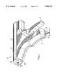
- FIG. 1is a perspective view of one embodiment of the coring device
- FIG. 2is a perspective view of the coring device shown in FIG. 1 with housing half-sections separated;
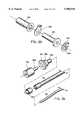
- FIG. 3is a perspective view with parts separated of the coring device shown in FIG. 1;
- FIG. 4is a perspective view with parts separated of the drive assembly of the coring device shown in FIG. 1;
- FIG. 5is a perspective view with parts separated of the rotation assembly and advancement assembly of the coring device shown in FIG. 1;
- FIG. 6is a front perspective view with parts separated of the movable handle and the actuation gear of the coring device shown in FIG. 1;
- FIG. 7is a rear perspective view with parts separated of the back side of the movable trigger and the actuation gear of the coring device shown in FIG. 1;
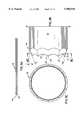
- FIG. 8Ais a side elevational view of a preferred coring member suitable for use with the coring devices shown in FIGS. 1 and 16;
- FIG. 8Bis an enlarged side elevational view of the distal end of the coring member shown in FIG. 8A.
- FIG. 8Cis an elevational view of the coring member taken along line 8C in FIG. 8B.
- FIG. 9is a side cross-sectional view of the coring device shown in FIG. 1;
- FIG. 10is an enlarged view of the indicated area of detail of FIG. 9;
- FIG. 11is an enlarged view of the indicated area of detail of FIG. 9;
- FIG. 12is an enlarged view of the indicated area of detail of FIG. 9;
- FIG. 13is a side cross-sectional view of the device shown in FIG. 1 with the movable trigger in position to actuate the advancement mechanism;
- FIG. 13Ais an enlarged partial side view of the coring device illustrating a stroke control assembly of the device shown in FIG. 1;
- FIG. 14is a perspective view which illustrates the coring device shown in FIG. 1 in position adjacent body tissue with the coring member in an extended position;
- FIG. 14Ais a side view of a biopsy retrieval assembly connected to the coring device shown in FIG. 1;
- FIG. 15is a perspective view of another embodiment of the coring device in association with a control assembly
- FIG. 16is a perspective view of the coring device shown in FIG. 15;
- FIG. 17is a perspective view with parts partially separated of the coring device shown in FIG. 15;
- FIG. 18is a perspective view with parts separated of the coring device shown in FIG. 15;
- FIG. 19is a perspective view with parts separated illustrating the clamping nut, the member adapter, the elongated shaft, and the coring member of the coring device shown in FIG. 15;
- FIG. 20is a side cross-sectional view of the coring device shown in FIG. 15;
- FIG. 21is an enlarged side cross-sectional view of the distal end of the coring device shown in FIG. 15;
- FIG. 22is a partial perspective view of the distal end of the coring device shown in FIG. 15 with a housing half-section removed;
- FIG. 23is a perspective view with parts separated of the cautery assembly of the coring device shown in FIG. 15;
- FIG. 24is a perspective view with parts separated of the swivel assembly and its adjacent components of the coring device shown in FIG. 15;
- FIG. 25is a side cross-sectional view of the coring device shown in FIG. 15 with the coring member in an extended position.
- coring device of the present disclosureWhile the preferred embodiments of the coring device of the present disclosure are useful to perform biopsy retrieval, bone marrow retrieval, and other similar procedures, the presently disclosed coring devices are particularly suited to perform Transmyocardial Revascularization (TMR). The preferred embodiments of coring device will, therefore, be described in connection with their use in performing TMR.
- TMRTransmyocardial Revascularization
- FIGS. 1 and 2illustrate the coring device shown generally as 10.
- coring device 10includes a housing 12 formed from molded housing half-sections 12a and 12b.
- Housing 12includes an elongated body portion 11 defining the longitudinal axis of device 10 and a stationary handle 14 projecting from elongated body portion 11.
- a movable trigger 16is pivotably connected to housing 12 adjacent stationary handle 14 forming a pistol type grip.
- a first opening 17 dimensioned to receive coring member 20is formed in one end of body portion 11.
- a second opening 21 formed in the free end of stationary handle 14allows passage of power supply cable 18 into housing 12.
- FIGS. 2 and 3illustrate the internal components of coring device 10 which will now be discussed in detail.
- Housing half-sections 12a and 12bare formed with internal recesses configured to properly align the internal components of the device with respect to each other and to restrict the movable components to a predetermined path of travel.
- Coring device 10includes a member drive assembly, a member rotation assembly, and a member advancement assembly.
- FIG. 4illustrates the member drive assembly "X" which includes a motor 22 which is adapted to be electrically connected to power supply cable 18.
- Motor 22drives output shaft 23 which is coupled to a cylindrical shaft 24 by a locking screw 25. Rotation of output shaft 23 translates to rotation of cylindrical shaft 24.
- a worm 26 and a bevel gear 28are slidably received and fastened about cylindrical shaft 24 by locking screws 27 and 29, respectively.
- cylindrical shaft 24rotates causing worm 26 and bevel gear 28 to also rotate.
- the member rotation assembly “Y”includes a bevel gear 34 having a rectangular bore 35 extending therethrough.
- a rod member 36 having a rectangular central portion 38is positioned within rectangular bore 35 of bevel gear 34 such that rotation of bevel gear 34 causes corresponding rotation of rod member 36.
- Rod member 36further includes a longitudinal throughbore 31 dimensioned to receive coring member 20, a threaded first end 39, and a cylindrical second end 37. Cylindrical second end 37 of rod member 36 interconnects rotation assembly "Y” and advancement assembly “Z", to be discussed in detail below.
- a flexible annular washer 50is positioned within cylindrical bore 49 between an inwardly extending flange 51 on the compression nut 48 and the threaded first end of rod member 36. See FIG. 11.
- Coring member 20extends proximal to advancement mechanism "Z" through rod member 36 and compression nut 48 towards the distal end of body portion 11.
- flexible washer 50is compressed and deformed into engagement with coring member 20 extending therethrough, thus securing coring member 20 to compression nut 48.
- Bevel gear 28 of member drive assembly “X”engages bevel gear 34 of member rotation assembly “Y”.
- bevel gear 28is rotated, rotating bevel gear 34 and rod member 36. Since rod member 36 is threadingly fastened to compression nut 48, compression nut 48 is also rotated.
- Flexible washer 50rotates with compression nut 48 and is frictionally engaged with coring member 20 to rotate coring member 20.
- the member advancement assembly “Z”includes a cylindrical member 40 having a central throughbore 42 and a toothed rack 52.
- Cylindrical member 40has a slot 54 configured to receive toothed rack 52 such that the teeth on toothed rack 52 extend outwardly from the outer periphery of cylindrical member 40.
- a pair of pins 56may be used to lock toothed rack 52 within slot 54.
- a first and a second gear setare positioned within the housing 12 of coring device 10.
- the first gear setincludes gear 58 and worm gear 60 which are fixedly mounted on a common rotatable shaft 62 by locking screws 64 and 66, respectively.
- the second gear setincludes gears 68 and 70 which are fixedly mounted on a common rotatable shaft 72 by locking screws 74 and 76. Shafts 62 and 72 are mounted for rotation between cylindrical recesses formed in housing half-sections 12a and 12b.
- Worm gear 60 of the first gear setengages worm 26 of member drive assembly "X" such that rotation of worm 26 causes rotation of worm gear 60. Since gear 58 and worm gear 60 are secured to common shaft 62, rotation of worm gear 60 causes corresponding rotation of shaft 62 and gear 58. Gear 72 of the second gear set engages an actuation gear 78 which is rotatably mounted to movable trigger 16. Likewise, since gears 68 and 70 are secured to common shaft 72, rotation of gear 68 causes corresponding rotation of shaft 72 and gear 70.
- FIGS. 6 and 7illustrate movable trigger 16 and actuation gear 78.
- Movable trigger 16has a shaft 80 and a guide projection 82.
- Actuation gear 78includes a central hub 84 which is rotatably mounted on shaft 80.
- the guide projection 82is slidably received within a semi-circular slot 86 formed housing half-section 12b (FIG. 3), and is retained therein by attachment of housing half-section 12a to housing half-section 12b.
- Actuation gear 78is in continuous engagement with gear 68 of the second gear set.
- actuation gear 78is moved to a position also engaging gear 58 of the first gear set.
- worm 26 of member drive assembly "X"engages worm gear 60 of the first gear set.
- worm 26is rotated by shaft 24, causing worm gear 60 to rotate.
- Rotation of worm gear 60results in corresponding rotation of shaft 62 and gear 58.
- actuation gear 78is caused to rotate. Since actuation gear 78 is engaged with gear 68 of the second gear set, gear 68 is rotated causing rotation of shaft 72 and gear 70.
- Gear 70engages toothed rack 52, such that rotation of gear 70 is translated to linear movement of rack 52 and cylindrical member 40.
- a cylindrical bearing 88 having a central bore 90 dimensioned to be slidably received about cylindrical bearing surface 37 of rod member 36is fitted within a cylindrical recess 93 formed in a first end 92 of cylindrical member 40. See FIG. 12.
- Bearing surface 37is rotatable within central bore 90 to allow rod member 36 to rotate with respect to cylindrical member 40.
- the first end 92 of cylindrical member 40engages an outer peripheral face 94 of the rectangular central portion 38 of rod member 36, such that linear movement of cylindrical member 40 causes linear movement of rod member 36, compression nut 48, and coring member 20.
- Coring member 20includes an elongated tubular member 96 having a central throughbore 94.
- the tubular member 96preferably extends through the central throughbores of cylindrical member 40, bearing 88, bevel gear 34, rod member 36, flexible washer 50, and compression nut 48.
- a first end 98 of tubular member 96extends from throughbore 42 of cylindrical member 40.
- the second end 100 of tubular member 96extends from a forward end of threaded throughbore 49 of compression nut 48 towards opening 17 in housing 12.
- the second end of the tubular member 96includes a cutting edge 102 which can be in the form of a flattened or a beveled edge.
- the cutting edge 102is in the form of a serrated annular edge 104.
- Cutting edge 102is formed from a plurality of spaced serrations formed at an angle with respect to the longitudinal axis of coring member 20.
- the serrationsare flat cuts (see FIG. 8C) but can also be contoured such as, for example, being concave or convex.
- the serrationshave a tooth depth ⁇ t ⁇ , which is defined by the longitudinal distance between the distal-most portion of the serration edge 105 and the proximal-most portion of the serration edge 107.
- the tooth depth ⁇ t ⁇preferably ranges from about 0.05 mm to about 0.3 mm.
- the angle ⁇ at which the serrations are cutpreferably ranges from about 5° to about 40° while the number of serrations ⁇ n ⁇ preferably ranges from about 4 to about 20.
- FIG. 8A-8C depict 10 serrations (n10) cut at an angle of 20°.
- the following tablesets forth several examples of preferred coring member dimensions when the serration angle ⁇ 100 ⁇ is 20°.
- the coring member 20can be advanced at a rate of between about 0.1 to about 50 mm/sec and simultaneously rotated at a rate of between about 1 to about 3000 rpm. Ideally, when coring body tissue, the coring member is advanced at a rate of between about 2 to about 4 mm/sec and simultaneously rotated at a rate of between about 100 to about 140 rpm. Coring has been accomplished in canine heart tissue where the coring member 20 was advanced at a rate of about 3 mm/sec and rotated at a rate of 120 rpm.
- the diameter of the coring member 20is preferably between about 0.1 to about 5 mm and most preferably about 2 mm.
- the rate of linear advancement of the coring member through tissueis not greater than the rate of cutting of the serrated edge of the coring member.
- the maximum cutting ratecan be calculated as follows:
- Number of serrated teeth ⁇ n ⁇ tooth depth (t) ⁇ rpmFor example, a 2.1 mm (O.D.) member having 10 teeth and a tooth depth of 0.147 mm rotating at 120 rpm is preferably advanced at a rate of about 176 mm/min (2.9 mm/sec). Advancing at a rate faster than described above may cause the member edge to longitudinally cut or tear tissue. Such an event decreases the likelihood of obtaining reproducible cores.
- the degree of linear cutting or tearingcan be controlled by the presently disclosed device, i.e., by controllably advancing the coring member at a controlled rate faster than the cutting rate described above.
- coring device 10can include a suction adapter 106 including tubular extension 108 and an outlet port 110.
- the suction adapter 106is supported within the housing 12 adjacent the rear end of the cylindrical member 40.
- a central throughbore (not shown) in tubular extension 108slidably receives and sealingly engages first end 98 of tubular member 96.
- First end 98 of tubular member 96should extend within tubular extension 108 a distance greater than the maximum stroke of coring member 20 to maintain vacuum communication during operation.
- the outlet port 110passes through an opening 122 formed in the housing 12, and may be connected to a receptacle 112 by a flexible vacuum line 114.
- Receptacle 112is connected to a conventional vacuum source 116. See FIG. 14A.
- Coring device 10can also include a cautery assembly including first and second contacts 116 and 118, respectively, and a dielectric spacer 120 (See FIGS. 3, 5 and 10).
- First contact 116includes a cylindrical body 128 that extends through opening 17 in housing 12.
- the cylindrical body 128has an annular edge 126 that projects outwardly from opening 17 beyond the outer surface of housing 12.
- Annular edge 126can be flat, but is preferably tapered to facilitate contact with body tissue.
- Dielectric spacer 120includes a cylindrical body portion 129 dimensioned to be received within a throughbore formed in first contact 116.
- the second contact 118abuts against spacer 120 and is positioned in electrical communication with coring member 20.
- Terminals 130 and 132extend through housing 12 and are connected to first and second contacts 116 and 118, respectively, via wires 134 and 136.
- the terminals 130 and 132are adapted to be connected to a suitable power source.
- the power sourcecan provide continuous power to the cautery assembly or provide a series of power pulses. Although shown in a bipolar configuration herein, monopolar configurations are also contemplated.
- an oscillatory assemblysuch as ultrasonic generator can be incorporated to impart oscillatory motion to the coring member 20.
- the ultrasonic generator 119 of this embodimentincludes a harmonic element supported between housing half-sections 12a and 12b in engagement with the advancing assembly "Y" of the coring device 10, and can be of the type disclosed in U.S. Pat. No. 5,026,387, issued on Jun. 25, 1991, to Thomas.
- a mounting structuresuch as keyed track (not shown), supports the ultrasonic generator within the housing 12 while permitting the ultrasonic generator 119 to move linearly as coring member 20 is advanced.
- the ultrasonic generator 119can be used in conjunction with the advancing and rotation assemblies to oscillate the coring member 20 as the member is rotated and advanced. Oscillation of the coring member can effect frictional cutting and/or cauterization of the tissue.
- the ultrasonic generator 119can also be operated solely in conjunction with the advancing assembly at a frequency coordinated with the rate of advancement of the advancing assembly to provide coring of body tissue.
- coring device 10When motor 22 is actuated, shaft 24 is rotated to rotate worm 26 and bevel gear 28. Bevel gear 28 engages and rotates bevel gear 34 which in turn rotates rod member 36 and compression nut 48. Coring member 20 is fastened to compression nut 48 by flexible washer 50, as illustrated in FIG. 11, such that coring member 20 rotates with compression nut 48.
- Worm 26engages worm gear 60 of the first gear set to rotate worm gear 60, rotatable shaft 62, and gear 58.
- actuation gear 78is rotated in the direction indicated by arrow "B".
- Actuation gear 78is engaged with gear 68 of the second gear set and rotates gear 68, rotatable shaft 72, and gear 70. Teeth on gear 70 engage teeth on toothed rack 52 to advance toothed rack 52 linearly in the direction indicated by arrow "C”.
- toothed rack 52is fastened to cylindrical member 40 and cylindrical member 40 engages peripheral face 44 of rod member 36, cylindrical member 40 and rod member 36 are also linearly advanced causing corresponding advancement of compression nut 48 and coring member 20 in the direction indicated by arrow "D".
- FIG. 13Aillustrates a control device to limit the distal advancement of coring member 20.
- the control device 10includes first and second motor contacts 134 and 136 which are removably mounted on any of a series of pegs 138 formed within housing half-section 12b to vary the maximum distance of advancement of coring member 20.
- Each contact 134 and 136electrically communicates with a corresponding terminal 141 and 143 of motor 22.
- Contacts 134 and 136are normally positioned in contact with each other such that when power is supplied to the motor 22 via cable 18, the circuit is complete and motor 22 is turned on.
- an annular flange 141is formed on compression nut 48.
- annular flange 140engages and deflects contact 136 to interrupt the motor circuit and stop motor 22.
- FIG. 14illustrates coring device 10 during a TMR procedure.
- the end face of the instrumentis placed against the tissue to be cored and motor 22 is operated to rotate coring member 22.
- movable trigger 16has been acted upon to actuate the linear advancement assembly to advance the coring member 20 from the epicardium 146 through the myocardium 148 and into the left ventricle 144 of the heart 149.
- 1 or more channelscan be cored into the heart to facilitate internal blood delivery to oxygen starved areas of the heart.
- thermal energycan be transferred from the member to the tissue by means of, for example, electrocautery or ultrasound. Such energy may affect the ability of the channel to remain open.
- a healthy human hearthas a wall thickness of 10-15 mm.
- a diseased heartcan be as thick as 40 mm (measured from the outer surface of the epicardium to the inner wall of the myocardium).
- the contacts 134 and 136should be properly positioned on pegs 138 prior to performing the TMR procedure to allow coring member 22 to core through the thickness of the heart being treated, i.e., the coring member should have a stroke length at least as great as the thickness of the heart wall to be perforated.
- Successful entry into the ventriclecan be visually apparent upon the appearance of blood in the vacuum line 114.
- FIG. 15illustrates a coring device 150, and a control assembly including a control module 152 and a foot operated actuator 154 for actuating the control module 152.
- a flexible shaft 188(see FIG. 17) wrapped in a shaft casing 176 extends between the control module 152 and the coring device 150.
- Flexible shaft 188should be of the type capable of transmitting both rotary and linear motion in the manner similar to a solid steel shaft, and can be of the type commercially available from S.S. White Technologies of Piscataway, N.J.
- Flexible shaft 188preferably has multiple layers of wire wrapped around a mandrel, with each layer being formed of multiple strands of wire.
- the control module 152includes dual-motion capability that can provide precise linear and rotary motion to flexible shaft 188. Two stepper motors can provide such motion.
- Flexible shaft 188is preferably coupled to the control module 152 and is rotated and advanced within shaft casing 176 and coring device 150. Motion of flexible shaft 188 is translated to the internal components of the coring device 150.
- a suitable dual-motion unit and the associated circuitry necessary to adapt the unit for use with the coring device 150 of the present disclosureis commercially available through Haydon Switch and Instrument, Inc. of Waterbury, Conn. or Eastern Air Devices, Inc. of Dover, N.H.
- Control module 152further includes a receptacle 156 adapted to engage a terminal of a programmable computer, such that control module 152 can interface with the computer.
- the software required to program the programmable dual-motion unitis commercially available through Intelligent Motion Systems, Inc. of Taftville, Conn.
- a toggle switch 158can be provided to switch the control module 152 from an operation mode to a test mode. In the test mode, when the foot actuator is acted upon, coring member 170 is moved sequentially from a fully retracted position to a fully extended position and back to the fully retracted position.
- the control module 152may also have a setting for servicing the coring member 170, such that when actuated, the coring member is extended without rotation to facilitate removal of the coring member 170 from the coring device 150.
- FIG. 16illustrates coring device 150.
- coring device 150includes a housing 160 formed from molded housing half-sections 162a and 162b.
- Housing 160includes an elongated body 164 having a first end 166 with an opening 168 dimensioned to permit reciprocation and rotation of coring member 170, and a second end 172 having an opening dimensioned to receive flexible shaft 188.
- a locator ring 178 having viewing ports 180can be integrally formed with, or removably attached to, the first end 166 of body 164.
- a locking screwcan be used to removably secure locator ring 178 to body 164.
- the locator ring 178is positioned about opening 168 and coring member 170 and can be positioned in engagement with the epicardial wall of the heart during a TMR procedure to help to properly orient the device with the heart.
- a suction adapter 182 and cautery terminals 184 and 186can be provided and positioned to extend through ports formed in housing 160.
- flexible shaft 188extends from control module 152 through shaft casing 176 and a swivel assembly 190 into the housing 160.
- the end of the flexible shaft 188 positioned within the housing 160is fastened to a linearly movable, rotatable piston 192.
- Piston 192is connected to an elongated shaft 194 via a threaded connector 196.
- Elongated shaft 194extends distally through a suction chamber 198 and is connected at its distal end to a member adapter 200 (FIG. 19) by clamping nut 202.
- Coring member 170is removably secured within member adapter 200 by the clamping nut 202.
- the flexible shaft 188, piston 192, connector 196, elongated shaft 194, member adapter 200, and member 170are fastened together to translate rotary and linear motion of shaft 188 to corresponding motion of the components listed above.
- member adapter 200preferably includes a plurality of annularly positioned flexible legs 204 which extend longitudinally from a cylindrical base portion 205. Each leg 204 is formed with an increased diameter portion 212 and a tapered cam surface 206.
- the member adapter 200defines a central throughbore 208 having an internal diameter greater than the outer diameter of the coring member 170. Coring member 170 extends through central bore 208 of member adapter 200 and through a partially threaded throughbore 213 formed in clamping nut 202.
- the elongated shaft 194has a threaded end 216 dimensioned to engage partially threaded throughbore 213 of clamping nut 202.
- clamping nut 202With coring member 170 extending through member adapter 200 and clamping nut 202 and with the member adapter 200 positioned in throughbore 213 of clamping nut 202, clamping nut 202 is threadingly engaged to threaded end 216 of elongated shaft 194 to deflect flexible legs 204 into clamping engagement with coring member 170.
- Coring device 150can include a suction assembly to remove the cored tissue from the surgical site.
- the suction assemblyincludes suction adapter 182 and suction chamber 198.
- Suction chamber 198is fixedly positioned in a recess formed in housing half-sections 162a and 162b.
- the first end of suction chamber 198is formed with a bore 220 having substantially the same internal dimensions as the outer surface of elongated shaft 194.
- a flexible ring seal 222is positioned in a recess formed in the first end of the suction chamber 198 to seal the area between the elongated shaft 194 and the bore 220 while permitting the elongated shaft 194 to slide through the bore 220.
- the elongated shaft 194includes a pair of annular flanges 224 which define a seal recess 226.
- Flexible seal 228is positioned within seal recess 226 and engages the internal walls of suction chamber 198 as the elongated shaft 194 is reciprocated therethrough to define a sealed compartment 230.
- Elongated shaft 194is provided with a central bore 232 that extends from threaded end 216 of shaft 194 to a series of circumferentially aligned ports 234 formed in shaft 194. Ports 234 communicate with sealed compartment 230.
- Coring member 170has a central bore 236 in communication with central bore 232 of elongated shaft 194. Cored tissue entering the distal end of coring member 170 can travel through member 170, into bore 232 of shaft 194, through ports 234, and into sealed compartment 230.
- Suction adapter 182has a central bore that communicates with sealed compartment 230 and an outlet port 238. As illustrated in FIG. 14A with respect to device 10, outlet port 238 may be similarly connected to a receptacle 112 by a flexible tube 114. Receptacle 112 is connected to a conventional vacuum source 116.
- FIGS. 21-23illustrate a cautery assembly which can be incorporated into coring device 170.
- the cautery assemblyincludes first and second contacts 240 and 242, a cylindrical dielectric spacer 244 and a conductive cylindrical member 246.
- First contact 240has a pair of flexible tabs 248 that engage coring member 170 that is constructed from an electrically conductive material.
- Second contact 242engages cylindrical member 246, and is separated from first contact 240 by dielectric spacer 244.
- Cylindrical member 246extends through opening 174 and is positioned about coring member 170, and includes an annular edge 250 that projects outwardly from opening 174. Annular edge 250 can be flat, but is preferably tapered to enhance contact with body tissue.
- Dielectric spacer 244is positioned between coring member 170 and cylindrical member 246 to prevent arcing between the two members.
- First and second contacts 240 and 242are electrically connected to cautery terminals 184 and 186 by wires 252 and 254. Terminals 184 and 186 are adapted to be connected to a suitable power source. Power can be supplied to the cautery assembly continuously during the coring procedure or supplied in timed pulses.
- Swivel assembly 190is positioned at the second end of housing 172.
- Swivel assembly 190includes a swivel coupling 256 rotatably positioned within an annular recess formed in housing half-sections 162a and 162b.
- the swivel coupling 256has a cylindrical extension 260 about which casing 176 extends.
- Annular clamp 258is positioned about extension 260 and casing 176 to secure casing 176 to swivel coupling 256.
- Flexible shaft 188extends through swivel coupling 256 and is crimped within a rearwardly extending portion 266 of piston 192. See FIG. 20.
- Coring device housing 160is rotatable about swivel coupling 256 independently of the internal components of the device 150.
- control module 152when control module 152 is actuated to provide linear and rotary motion to flexible shaft 188, this motion is translated to piston 192, connector 196, elongated shaft 194, member adapter 200, and clamping nut 202 to linearly advance and rotate coring member 170 in the direction indicated by arrow "F".
- Control module 152can be programmed to provide either rotation of shaft 188 in one direction or oscillatory rotation of shaft 188. It is noted that the distal end of coring member 170 can be identical to coring member 20 and will not be discussed in detail. Similarly, the preferred rates of advancement and rotation for performing a TMR procedure can be identical to those disclosed with respect to coring device 10 and will not be discussed in detail.
- the coring toolneed not be hollow throughout the entire length and can be closed at the proximal end. Therefore, the above description should not be construed as limiting, but merely as exemplifications of preferred embodiments. Those skilled in the art will envision other modifications within the scope and spirit of the claims appended thereto.
Landscapes
- Health & Medical Sciences (AREA)
- Life Sciences & Earth Sciences (AREA)
- Surgery (AREA)
- Engineering & Computer Science (AREA)
- Medical Informatics (AREA)
- Veterinary Medicine (AREA)
- Biomedical Technology (AREA)
- Heart & Thoracic Surgery (AREA)
- Nuclear Medicine, Radiotherapy & Molecular Imaging (AREA)
- Molecular Biology (AREA)
- Animal Behavior & Ethology (AREA)
- General Health & Medical Sciences (AREA)
- Public Health (AREA)
- Physics & Mathematics (AREA)
- Plasma & Fusion (AREA)
- Otolaryngology (AREA)
- Orthopedic Medicine & Surgery (AREA)
- Surgical Instruments (AREA)
Abstract
Description
1. Technical Field
The present disclosure relates generally to a coring device for surgical use. More specifically, the present disclosure relates to a coring device having an advanceable member operated at a coordinated speed to facilitate reproducible coring of body tissue. The coring device is particularly suited for use in performing transmyocardial revascularization (TMR).
2. Background of the Related Art
Mechanical coring devices suitable for use in surgical procedures such as biopsy retrieval, bone marrow retrieval, and similar procedures are well known. Typically, these coring devices include a tubular body having a sharpened end, and a cutting member. During coring procedures, the tubular body is manually advanced into body tissue such that a core of material is retrieved and retained within the tubular body. Thereafter, the cored tissue is removed for analysis.
One problem associated with these devices is that variations in the rate of advancement of the tubular body into the body tissue effect the size and shape of the cored tissue sample, e.g., a high rate of advancement can cause tearing of body tissue rather than precise coring of the tissue. Because of this, manual advancement makes it very difficult to retrieve good tissue samples of consistent size and shape required for biopsy. U.S. Pat. No. 4,461,305 issued to Cibley, addresses the problem of obtaining more consistent tissue sample sizes. Cibley discloses a biopsy device having a rotatable shaft with a cutting edge at its distal end. As the shaft is rotated, a trigger is compressed to manually advance the shaft into body tissue. Although Cibley improves upon the prior art, the performance of Cibley's device is directly related to the rate at which the shaft is manually advanced into the body tissue. Because the shaft is manually advanced, reproducible coring for the particular body tissue is difficult to achieve.
Mechanical devices have also been used in other surgical procedures. One such procedure is Transmyocardial Revascularization (TMR). In this procedure, surgical needles, biopsy needles, cannulas or similar instruments have been used to produce channels from the epicardium, through the myocardium and into the ventricle of the heart. It is believed that these channels facilitate delivery of blood directly from the ventrical to the oxygen starved areas of the heart. When performing a TMR procedure, 1 or more and typically dozens of channels are created in the heart. Because heart tissue has a soft, spongy texture that can be easily torn or deformed, it is difficult, if not impossible, to create consistent, reproducible channels by the aforementioned manual puncturing and coring techniques.
Accordingly, a need exists for an improved mechanical coring device that is easy to use, consistent and reliable when coring channels in body tissue.
In accordance with the present disclosure, a coring device is provided that is capable of consistently coring channels of common size and shape in body tissue. The coring device can include a rotation assembly for rotating a coring member, and an advancement assembly for linearly advancing the coring member. An oscillator assembly can also be incorporated to assist in coring tissue. The rotation assembly and the advancement assembly are preferably driven to coordinate the rate of rotation of the coring member with the rate of linear advancement of the member. Both longitudinal and rotational reciprocation of the coring member can also be used to effect efficient coring. The coring device can be used to perform biopsy retrieval, bone marrow retrieval and other similar procedures, but is particularly suited to perform TMR.
In a first preferred embodiment of the disclosure, a drive assembly is supported within a housing of the coring device and includes a motor that is coupled to a rotatable rod having a bevel gear and a worm fixed thereto. The bevel gear is operably associated with the rotation assembly to rotate the coring member when the motor is operated. The worm is operably associated with the coring member such that the worm can be selectively coupled to drive a toothed rack to advance the coring member linearly. The rates of rotation and advancement of the coring member are coordinated to provide a reproducible cored channel in body tissue.
In another preferred embodiment, the driving assembly is incorporated into a dual-motion, independently programmable, control module that translates precise linear and rotary motion to a coring member via a flexible shaft. The device is preferably operated by a foot pedal which is operably connected to the control module to advance and rotate the coring member.
Various preferred embodiments are described herein with reference to the drawings, wherein:
FIG. 1 is a perspective view of one embodiment of the coring device;
FIG. 2 is a perspective view of the coring device shown in FIG. 1 with housing half-sections separated;
FIG. 3 is a perspective view with parts separated of the coring device shown in FIG. 1;
FIG. 4 is a perspective view with parts separated of the drive assembly of the coring device shown in FIG. 1;
FIG. 5 is a perspective view with parts separated of the rotation assembly and advancement assembly of the coring device shown in FIG. 1;
FIG. 6 is a front perspective view with parts separated of the movable handle and the actuation gear of the coring device shown in FIG. 1;
FIG. 7 is a rear perspective view with parts separated of the back side of the movable trigger and the actuation gear of the coring device shown in FIG. 1;
FIG. 8A is a side elevational view of a preferred coring member suitable for use with the coring devices shown in FIGS. 1 and 16;
FIG. 8B is an enlarged side elevational view of the distal end of the coring member shown in FIG. 8A.
FIG. 8C is an elevational view of the coring member taken alongline 8C in FIG. 8B.
FIG. 9 is a side cross-sectional view of the coring device shown in FIG. 1;
FIG. 10 is an enlarged view of the indicated area of detail of FIG. 9;
FIG. 11 is an enlarged view of the indicated area of detail of FIG. 9;
FIG. 12 is an enlarged view of the indicated area of detail of FIG. 9;
FIG. 13 is a side cross-sectional view of the device shown in FIG. 1 with the movable trigger in position to actuate the advancement mechanism;
FIG. 13A is an enlarged partial side view of the coring device illustrating a stroke control assembly of the device shown in FIG. 1;
FIG. 14 is a perspective view which illustrates the coring device shown in FIG. 1 in position adjacent body tissue with the coring member in an extended position;
FIG. 14A is a side view of a biopsy retrieval assembly connected to the coring device shown in FIG. 1;
FIG. 15 is a perspective view of another embodiment of the coring device in association with a control assembly;
FIG. 16 is a perspective view of the coring device shown in FIG. 15;
FIG. 17 is a perspective view with parts partially separated of the coring device shown in FIG. 15;
FIG. 18 is a perspective view with parts separated of the coring device shown in FIG. 15;
FIG. 19 is a perspective view with parts separated illustrating the clamping nut, the member adapter, the elongated shaft, and the coring member of the coring device shown in FIG. 15;
FIG. 20 is a side cross-sectional view of the coring device shown in FIG. 15;
FIG. 21 is an enlarged side cross-sectional view of the distal end of the coring device shown in FIG. 15;
FIG. 22 is a partial perspective view of the distal end of the coring device shown in FIG. 15 with a housing half-section removed;
FIG. 23 is a perspective view with parts separated of the cautery assembly of the coring device shown in FIG. 15;
FIG. 24 is a perspective view with parts separated of the swivel assembly and its adjacent components of the coring device shown in FIG. 15; and
FIG. 25 is a side cross-sectional view of the coring device shown in FIG. 15 with the coring member in an extended position.
Preferred embodiments of the presently disclosed coring device will now be described in detail with reference to the drawings, in which like reference numerals designate identical or corresponding elements in each of the several views.
While the preferred embodiments of the coring device of the present disclosure are useful to perform biopsy retrieval, bone marrow retrieval, and other similar procedures, the presently disclosed coring devices are particularly suited to perform Transmyocardial Revascularization (TMR). The preferred embodiments of coring device will, therefore, be described in connection with their use in performing TMR.
One embodiment of the presently disclosed coring device will now be described with reference to FIGS. 1-14A. FIGS. 1 and 2 illustrate the coring device shown generally as 10. Briefly, coring device 10 includes ahousing 12 formed from molded housing half-sections 12a and 12b.Housing 12 includes an elongated body portion 11 defining the longitudinal axis of device 10 and astationary handle 14 projecting from elongated body portion 11. Amovable trigger 16 is pivotably connected tohousing 12 adjacentstationary handle 14 forming a pistol type grip. Afirst opening 17 dimensioned to receivecoring member 20 is formed in one end of body portion 11. A second opening 21 formed in the free end ofstationary handle 14 allows passage ofpower supply cable 18 intohousing 12.
FIGS. 2 and 3 illustrate the internal components of coring device 10 which will now be discussed in detail. Housing half-sections 12a and 12b are formed with internal recesses configured to properly align the internal components of the device with respect to each other and to restrict the movable components to a predetermined path of travel. Coring device 10 includes a member drive assembly, a member rotation assembly, and a member advancement assembly. FIG. 4 illustrates the member drive assembly "X" which includes amotor 22 which is adapted to be electrically connected topower supply cable 18.Motor 22 drivesoutput shaft 23 which is coupled to acylindrical shaft 24 by a lockingscrew 25. Rotation ofoutput shaft 23 translates to rotation ofcylindrical shaft 24. Aworm 26 and abevel gear 28 are slidably received and fastened aboutcylindrical shaft 24 by lockingscrews output shaft 23,cylindrical shaft 24rotates causing worm 26 andbevel gear 28 to also rotate.
Referring to FIG. 5, the member rotation assembly "Y" includes abevel gear 34 having arectangular bore 35 extending therethrough. Arod member 36 having a rectangularcentral portion 38 is positioned withinrectangular bore 35 ofbevel gear 34 such that rotation ofbevel gear 34 causes corresponding rotation ofrod member 36.Rod member 36 further includes alongitudinal throughbore 31 dimensioned to receivecoring member 20, a threadedfirst end 39, and a cylindricalsecond end 37. Cylindricalsecond end 37 ofrod member 36 interconnects rotation assembly "Y" and advancement assembly "Z", to be discussed in detail below.
Acompression nut 48 having a threadedcylindrical bore 49 threadingly engages thefirst end 39 ofrod member 36. A flexibleannular washer 50 is positioned withincylindrical bore 49 between an inwardly extendingflange 51 on thecompression nut 48 and the threaded first end ofrod member 36. See FIG. 11. Coringmember 20 extends proximal to advancement mechanism "Z" throughrod member 36 andcompression nut 48 towards the distal end of body portion 11. Ascompression nut 48 is threaded ontorod member 36,flexible washer 50 is compressed and deformed into engagement withcoring member 20 extending therethrough, thus securingcoring member 20 tocompression nut 48.
The member advancement assembly "Z" includes acylindrical member 40 having a central throughbore 42 and atoothed rack 52.Cylindrical member 40 has aslot 54 configured to receivetoothed rack 52 such that the teeth ontoothed rack 52 extend outwardly from the outer periphery ofcylindrical member 40. A pair ofpins 56 may be used to locktoothed rack 52 withinslot 54.
As shown in FIGS. 2 and 3, a first and a second gear set are positioned within thehousing 12 of coring device 10. The first gear set includesgear 58 andworm gear 60 which are fixedly mounted on acommon rotatable shaft 62 by lockingscrews gears common rotatable shaft 72 by lockingscrews 74 and 76.Shafts sections 12a and 12b.
FIGS. 6 and 7 illustratemovable trigger 16 andactuation gear 78.Movable trigger 16 has ashaft 80 and aguide projection 82.Actuation gear 78 includes a central hub 84 which is rotatably mounted onshaft 80. Theguide projection 82 is slidably received within asemi-circular slot 86 formed housing half-section 12b (FIG. 3), and is retained therein by attachment of housing half-section 12a to housing half-section 12b.Actuation gear 78 is in continuous engagement withgear 68 of the second gear set. Whenmovable trigger 16 is actuated to moveguide projection 82 alongslot 86,actuation gear 78 is moved to a position also engaginggear 58 of the first gear set.
As stated above,worm 26 of member drive assembly "X" engagesworm gear 60 of the first gear set. Upon actuation ofmotor 22,worm 26 is rotated byshaft 24, causingworm gear 60 to rotate. Rotation ofworm gear 60 results in corresponding rotation ofshaft 62 andgear 58. Whenmovable trigger 16 is acted upon to moveactuation gear 78 into engagement withgear 58,actuation gear 78 is caused to rotate. Sinceactuation gear 78 is engaged withgear 68 of the second gear set,gear 68 is rotated causing rotation ofshaft 72 andgear 70.Gear 70 engagestoothed rack 52, such that rotation ofgear 70 is translated to linear movement ofrack 52 andcylindrical member 40.
Referring again to FIG. 5, acylindrical bearing 88 having acentral bore 90 dimensioned to be slidably received aboutcylindrical bearing surface 37 ofrod member 36 is fitted within a cylindrical recess 93 formed in afirst end 92 ofcylindrical member 40. See FIG. 12. Bearingsurface 37 is rotatable withincentral bore 90 to allowrod member 36 to rotate with respect tocylindrical member 40. Further, thefirst end 92 ofcylindrical member 40 engages an outerperipheral face 94 of the rectangularcentral portion 38 ofrod member 36, such that linear movement ofcylindrical member 40 causes linear movement ofrod member 36,compression nut 48, and coringmember 20.
Coringmember 20 includes anelongated tubular member 96 having acentral throughbore 94. Thetubular member 96 preferably extends through the central throughbores ofcylindrical member 40, bearing 88,bevel gear 34,rod member 36,flexible washer 50, andcompression nut 48. Afirst end 98 oftubular member 96 extends from throughbore 42 ofcylindrical member 40. Thesecond end 100 oftubular member 96 extends from a forward end of threadedthroughbore 49 ofcompression nut 48 towards opening 17 inhousing 12. The second end of thetubular member 96 includes acutting edge 102 which can be in the form of a flattened or a beveled edge.
Preferably, as illustrated in FIGS. 8A-8C, thecutting edge 102 is in the form of a serratedannular edge 104. Cuttingedge 102 is formed from a plurality of spaced serrations formed at an angle with respect to the longitudinal axis of coringmember 20. Preferably the serrations are flat cuts (see FIG. 8C) but can also be contoured such as, for example, being concave or convex. As shown, the serrations have a tooth depth `t`, which is defined by the longitudinal distance between the distal-most portion of theserration edge 105 and the proximal-most portion of theserration edge 107. The tooth depth `t` preferably ranges from about 0.05 mm to about 0.3 mm. The angle `φ` at which the serrations are cut preferably ranges from about 5° to about 40° while the number of serrations `n` preferably ranges from about 4 to about 20. FIG. 8A-8C depict 10 serrations (n=10) cut at an angle of 20°. The following table sets forth several examples of preferred coring member dimensions when the serration angle `100` is 20°.
______________________________________ Member Inner Number of Diameter Member Diameter Tooth Depth Serrations (mm) (mm) (mm) ______________________________________ 8 2.1 1.9 0.203 (0.0080") 10 2.1 1.9 0.147 (0.0058") 12 2.1 1.9 0.091 (0.0036") 8 1.8 1.6 0.170 (0.0067") 10 1.8 1.6 0.112 (0.0044") 12 1.8 1.6 0.084 (0.0033") 8 1.65 1.37 0.152 (0.0060") 10 1.65 1.37 0.102 (0.0040") 12 1.65 1.37 0.076 (0.0030") 8 1.42 1.17 0.132 (0.0052") 10 1.42 1.17 0.081 (0.0032") 12 1.42 1.17 0.066 (0.0026") ______________________________________
The coringmember 20 can be advanced at a rate of between about 0.1 to about 50 mm/sec and simultaneously rotated at a rate of between about 1 to about 3000 rpm. Ideally, when coring body tissue, the coring member is advanced at a rate of between about 2 to about 4 mm/sec and simultaneously rotated at a rate of between about 100 to about 140 rpm. Coring has been accomplished in canine heart tissue where the coringmember 20 was advanced at a rate of about 3 mm/sec and rotated at a rate of 120 rpm. The diameter of the coringmember 20 is preferably between about 0.1 to about 5 mm and most preferably about 2 mm.
Preferably, the rate of linear advancement of the coring member through tissue is not greater than the rate of cutting of the serrated edge of the coring member. In a preferred embodiment, the maximum cutting rate can be calculated as follows:
Number of serrated teeth `n`×tooth depth (t)×rpm. For example, a 2.1 mm (O.D.) member having 10 teeth and a tooth depth of 0.147 mm rotating at 120 rpm is preferably advanced at a rate of about 176 mm/min (2.9 mm/sec). Advancing at a rate faster than described above may cause the member edge to longitudinally cut or tear tissue. Such an event decreases the likelihood of obtaining reproducible cores. As far as TMR is concerned, as well as other coring procedures, if some degree of linear cutting or tearing is desirable (i.e., increases the likelihood of the channels remaining open) the degree of linear cutting or tearing can be controlled by the presently disclosed device, i.e., by controllably advancing the coring member at a controlled rate faster than the cutting rate described above. Those skilled in the art will learn by experimentation with the device and particular forms of tissue how to select cutting rate(s) and advancement rate(s) to obtain desired effects on the tissue.
With reference to FIGS. 2, 5 and 9, coring device 10 can include asuction adapter 106 includingtubular extension 108 and anoutlet port 110. Thesuction adapter 106 is supported within thehousing 12 adjacent the rear end of thecylindrical member 40. A central throughbore (not shown) intubular extension 108 slidably receives and sealingly engagesfirst end 98 oftubular member 96. First end 98 oftubular member 96 should extend within tubular extension 108 a distance greater than the maximum stroke of coringmember 20 to maintain vacuum communication during operation. Theoutlet port 110 passes through anopening 122 formed in thehousing 12, and may be connected to areceptacle 112 by a flexible vacuum line 114.Receptacle 112 is connected to aconventional vacuum source 116. See FIG. 14A.
Coring device 10 can also include a cautery assembly including first andsecond contacts First contact 116 includes acylindrical body 128 that extends through opening 17 inhousing 12. Thecylindrical body 128 has anannular edge 126 that projects outwardly from opening 17 beyond the outer surface ofhousing 12.Annular edge 126 can be flat, but is preferably tapered to facilitate contact with body tissue.
Referring to FIGS. 9 and 13, in one embodiment, an oscillatory assembly such as ultrasonic generator can be incorporated to impart oscillatory motion to the coringmember 20. Theultrasonic generator 119 of this embodiment includes a harmonic element supported between housing half-sections 12a and 12b in engagement with the advancing assembly "Y" of the coring device 10, and can be of the type disclosed in U.S. Pat. No. 5,026,387, issued on Jun. 25, 1991, to Thomas. A mounting structure, such as keyed track (not shown), supports the ultrasonic generator within thehousing 12 while permitting theultrasonic generator 119 to move linearly as coringmember 20 is advanced. Theultrasonic generator 119 can be used in conjunction with the advancing and rotation assemblies to oscillate the coringmember 20 as the member is rotated and advanced. Oscillation of the coring member can effect frictional cutting and/or cauterization of the tissue. Theultrasonic generator 119 can also be operated solely in conjunction with the advancing assembly at a frequency coordinated with the rate of advancement of the advancing assembly to provide coring of body tissue.
Operation of coring device 10 will now be described with reference to FIG. 13. As discussed above, whenmotor 22 is actuated,shaft 24 is rotated to rotateworm 26 andbevel gear 28.Bevel gear 28 engages and rotatesbevel gear 34 which in turn rotatesrod member 36 andcompression nut 48. Coringmember 20 is fastened tocompression nut 48 byflexible washer 50, as illustrated in FIG. 11, such thatcoring member 20 rotates withcompression nut 48.
FIG. 13A illustrates a control device to limit the distal advancement ofcoring member 20. The control device 10 includes first andsecond motor contacts pegs 138 formed within housing half-section 12b to vary the maximum distance of advancement ofcoring member 20. Eachcontact corresponding terminal motor 22.Contacts motor 22 viacable 18, the circuit is complete andmotor 22 is turned on. To limit the distal advancement ofcoring member 20, anannular flange 141 is formed oncompression nut 48. Ascompression nut 48 is advanced a predetermined linear distance in the direction indicated by arrow "E",annular flange 140 engages and deflects contact 136 to interrupt the motor circuit and stopmotor 22. Areturn spring 143 positioned about coringmember 20 betweencautery contact 116 and compression nut 48 (see FIG. 5) returns the coringmember 20 to a retracted position. The return spring will not move the member untiltrigger 16 is released and the gears providing longitudinal motion are disengaged.
FIG. 14 illustrates coring device 10 during a TMR procedure. The end face of the instrument is placed against the tissue to be cored andmotor 22 is operated to rotate coringmember 22. In FIG. 14,movable trigger 16 has been acted upon to actuate the linear advancement assembly to advance the coringmember 20 from theepicardium 146 through themyocardium 148 and into theleft ventricle 144 of the heart 149. During the TMR procedure, 1 or more channels can be cored into the heart to facilitate internal blood delivery to oxygen starved areas of the heart. During or after the coring member has created a hole, thermal energy can be transferred from the member to the tissue by means of, for example, electrocautery or ultrasound. Such energy may affect the ability of the channel to remain open.
Typically, a healthy human heart has a wall thickness of 10-15 mm. A diseased heart can be as thick as 40 mm (measured from the outer surface of the epicardium to the inner wall of the myocardium). Thecontacts pegs 138 prior to performing the TMR procedure to allow coringmember 22 to core through the thickness of the heart being treated, i.e., the coring member should have a stroke length at least as great as the thickness of the heart wall to be perforated. Successful entry into the ventricle can be visually apparent upon the appearance of blood in the vacuum line 114.
An alternative embodiment of the presently disclosed coring device will now be described with reference to FIGS. 15-25. FIG. 15 illustrates acoring device 150, and a control assembly including acontrol module 152 and a foot operatedactuator 154 for actuating thecontrol module 152. A flexible shaft 188 (see FIG. 17) wrapped in ashaft casing 176 extends between thecontrol module 152 and thecoring device 150.Flexible shaft 188 should be of the type capable of transmitting both rotary and linear motion in the manner similar to a solid steel shaft, and can be of the type commercially available from S.S. White Technologies of Piscataway, N.J.Flexible shaft 188 preferably has multiple layers of wire wrapped around a mandrel, with each layer being formed of multiple strands of wire.
Thecontrol module 152 includes dual-motion capability that can provide precise linear and rotary motion toflexible shaft 188. Two stepper motors can provide such motion.Flexible shaft 188 is preferably coupled to thecontrol module 152 and is rotated and advanced withinshaft casing 176 andcoring device 150. Motion offlexible shaft 188 is translated to the internal components of thecoring device 150. A suitable dual-motion unit and the associated circuitry necessary to adapt the unit for use with thecoring device 150 of the present disclosure is commercially available through Haydon Switch and Instrument, Inc. of Waterbury, Conn. or Eastern Air Devices, Inc. of Dover, N.H.
FIG. 16 illustratescoring device 150. Briefly,coring device 150 includes ahousing 160 formed from molded housing half-sections 162a and 162b.Housing 160 includes anelongated body 164 having afirst end 166 with anopening 168 dimensioned to permit reciprocation and rotation of coringmember 170, and asecond end 172 having an opening dimensioned to receiveflexible shaft 188. Alocator ring 178 havingviewing ports 180 can be integrally formed with, or removably attached to, thefirst end 166 ofbody 164. A locking screw can be used to removablysecure locator ring 178 tobody 164. Thelocator ring 178 is positioned about opening 168 andcoring member 170 and can be positioned in engagement with the epicardial wall of the heart during a TMR procedure to help to properly orient the device with the heart. Asuction adapter 182 andcautery terminals housing 160.
Referring to FIGS. 17 and 18,flexible shaft 188 extends fromcontrol module 152 throughshaft casing 176 and aswivel assembly 190 into thehousing 160. The end of theflexible shaft 188 positioned within thehousing 160 is fastened to a linearly movable,rotatable piston 192.Piston 192 is connected to anelongated shaft 194 via a threadedconnector 196.Elongated shaft 194 extends distally through asuction chamber 198 and is connected at its distal end to a member adapter 200 (FIG. 19) by clampingnut 202.Coring member 170 is removably secured withinmember adapter 200 by the clampingnut 202. Theflexible shaft 188,piston 192,connector 196,elongated shaft 194,member adapter 200, andmember 170 are fastened together to translate rotary and linear motion ofshaft 188 to corresponding motion of the components listed above.
Referring to FIG. 19,member adapter 200 preferably includes a plurality of annularly positionedflexible legs 204 which extend longitudinally from acylindrical base portion 205. Eachleg 204 is formed with an increaseddiameter portion 212 and atapered cam surface 206. Themember adapter 200 defines acentral throughbore 208 having an internal diameter greater than the outer diameter of thecoring member 170.Coring member 170 extends throughcentral bore 208 ofmember adapter 200 and through a partially threadedthroughbore 213 formed in clampingnut 202.
As illustrated in FIGS. 20 and 21, theelongated shaft 194 has a threadedend 216 dimensioned to engage partially threadedthroughbore 213 of clampingnut 202. With coringmember 170 extending throughmember adapter 200 and clampingnut 202 and with themember adapter 200 positioned inthroughbore 213 of clampingnut 202, clampingnut 202 is threadingly engaged to threadedend 216 ofelongated shaft 194 to deflectflexible legs 204 into clamping engagement withcoring member 170.
FIGS. 21-23 illustrate a cautery assembly which can be incorporated intocoring device 170. The cautery assembly includes first andsecond contacts dielectric spacer 244 and a conductivecylindrical member 246.First contact 240 has a pair offlexible tabs 248 that engage coringmember 170 that is constructed from an electrically conductive material.Second contact 242 engagescylindrical member 246, and is separated fromfirst contact 240 bydielectric spacer 244.Cylindrical member 246 extends throughopening 174 and is positioned about coringmember 170, and includes anannular edge 250 that projects outwardly fromopening 174.Annular edge 250 can be flat, but is preferably tapered to enhance contact with body tissue.Dielectric spacer 244 is positioned betweencoring member 170 andcylindrical member 246 to prevent arcing between the two members.
First andsecond contacts cautery terminals wires Terminals
Referring now to FIG. 24, aswivel assembly 190 is positioned at the second end ofhousing 172.Swivel assembly 190 includes aswivel coupling 256 rotatably positioned within an annular recess formed in housing half-sections 162a and 162b. Theswivel coupling 256 has acylindrical extension 260 about whichcasing 176 extends.Annular clamp 258 is positioned aboutextension 260 andcasing 176 to securecasing 176 to swivelcoupling 256.Flexible shaft 188 extends throughswivel coupling 256 and is crimped within arearwardly extending portion 266 ofpiston 192. See FIG. 20.Coring device housing 160 is rotatable aboutswivel coupling 256 independently of the internal components of thedevice 150.
Referring now to FIG. 25, whencontrol module 152 is actuated to provide linear and rotary motion toflexible shaft 188, this motion is translated topiston 192,connector 196,elongated shaft 194,member adapter 200, and clampingnut 202 to linearly advance and rotatecoring member 170 in the direction indicated by arrow "F".Control module 152 can be programmed to provide either rotation ofshaft 188 in one direction or oscillatory rotation ofshaft 188. It is noted that the distal end of coringmember 170 can be identical to coringmember 20 and will not be discussed in detail. Similarly, the preferred rates of advancement and rotation for performing a TMR procedure can be identical to those disclosed with respect to coring device 10 and will not be discussed in detail.
It will be understood that various modifications can be made to the embodiments disclosed herein. For example, while specific preferred embodiments of driving, advancing, rotating, cauterizing and oscillation assemblies, have been described in detail, structures that perform substantially the same function in substantially the same way to achieve substantially the same result can also be used. Also, while electrical motors have been specifically disclosed herein, air, pneumatic, hydraulic or other types of motors can be used to advance and/or rotate the coring device. In addition, the cautery assemblies can include monopolar circuitry rather than bipolar circuitry as disclosed. Also, besides TMR, the coring device can be used to perform human and veterinary surgical procedures including biopsy retrieval, bone marrow retrieval and other similar procedures. Body tissue other than heart tissue can be cored including liver tissue, bone tissue, skin tissue, etc. Also, depending on the type of tissue and procedure, the coring tool need not be hollow throughout the entire length and can be closed at the proximal end. Therefore, the above description should not be construed as limiting, but merely as exemplifications of preferred embodiments. Those skilled in the art will envision other modifications within the scope and spirit of the claims appended thereto.
Claims (37)
1. A coring device comprising:
a housing defining a longitudinal axis;
a coring member mounted in said housing;
an advancing assembly mounted for engagement with said coring member to effect longitudinal motion thereof;
a drive assembly connected to said advancing assembly for activating said advancing assembly to move the coring member longitudinally at a predetermined rate to core body tissue; and
an electrical element connected to said coring member to provide cauterizing current to body tissue.
2. A coring device according to claim 1, further comprising a rotation assembly mounted for engagement with said coring member, said drive assembly connected to said rotation assembly for activating said rotation assembly to rotate the coring member in coordination with the longitudinal advancement of the coring member.
3. A coring device according to claim 1, further comprising an oscillation assembly mounted for engagement with said coring member, said oscillation assembly effecting oscillation of the coring member.
4. A coring device according to claim 3, wherein said oscillation assembly comprises an ultrasonic generator connected to the coring member.
5. A coring device comprising:
a coring member;
a rotation assembly operably connected to the coring member;
an advancing assembly operably connected to the coring member;
a drive assembly operably connected to the rotation assembly and advancing assembly, the drive assembly being operable to activate the rotation and advancing assembly to rotate and advance the coring member at predetermined coordinated rates to effect coring of body tissue; and
a control module, the control module including the drive assembly and being programmable to coordinate the rates of advancement and rotation of the coring member.
6. A coring device according to claim 5, wherein the coring member, the rotation assembly, the advancing assembly, and the drive assembly are supported within a single housing.
7. A coring device according to claim 6, further comprising a movable trigger, and wherein the advancing assembly includes an actuation gear actuated by the movable trigger, the movable trigger being selectively movable to operably connect the advancing assembly to the drive assembly to advance the coring member.
8. A coring device according to claim 7, further comprising an ultrasonic assembly operably connected to the coring member to oscillate the coring member.
9. A coring device according to claim 8, wherein the coring member is oscillated along its longitudinal axis.
10. A coring device according to claim 5, further comprising a cautery assembly operably connected to the coring member.
11. A coring device according to claim 5, wherein the drive assembly includes first and second stepper motors, the first stepper motor being operably connected to the advancing assembly and the second stepper motor being operably connected to the rotation assembly.
12. A coring device according to claim 11, further comprising a flexible shaft extending from the control module to the coring member, wherein said flexible shaft translates linear and rotary motion from the drive assembly to the coring member.
13. A coring device comprising:
a coring member;
a longitudinal oscillatory assembly operably connected to the coring member;
an advancing assembly operably connected to the coring member; and
a drive assembly operably connected to the oscillatory assembly and the advancing assembly, the drive assembly being operable to advance the coring member at predetermined coordinated rates to effect coring of body tissue while controlling the degree of tearing of the body tissue, wherein the drive assembly includes an electric motor and a harmonic generator, the electric motor being operably connected to the advancing assembly and the harmonic generator being operably connected to the oscillatory assembly.
14. A coring device comprising:
a coring member;
a rotation assembly operably connected to the coring member;
an advancing assembly operably connected to the coring member; and
a drive assembly operably connected to the rotation assembly and to the advancing assembly, the drive assembly being operable to activate the rotation and advancing assemblies to rotate and advance the coring member at predetermined coordinated rates to effect coring of body tissue, wherein during advancement of the coring member, the coring member is rotated at least one revolution.
15. A coring device comprising:
a coring member;
a longitudinal oscillatory assembly operably connected to the coring member;
an advancing assembly operably connected to the coring member; and
a drive assembly operably connected to the oscillatory assembly and the advancing assembly, the drive assembly being operable to simultaneously advance and oscillate the coring member at predetermined coordinated rates to effect coring of body tissue while controlling the degree of tearing of the body tissue.
16. A method of coring body tissue comprising the steps of:
(a) providing a coring device having a linearly advanceable, rotatable coring member;
(b) positioning the coring device adjacent to the body tissue to be cored;
(c) simultaneously advancing and rotating the coring member at predetermined coordinated rates to core the body tissue; and
(d) cauterizing the cored body tissue.
17. A method according to claim 16, wherein the predetermined rate of rotation is from about 1 to about 3000 rpm.
18. A method of according to claim 17, wherein the predetermined rate of rotation is between about 100 to about 140 rpm.
19. A method according to claim 18, predetermined rate of rotation is between about 120 rpm.
20. A method according to claim 16, wherein the predetermined rate of advancement is between about 0.1 to about 50 mm/sec.
21. A method according to claim 20, wherein the predetermined rate of advancement is between about 2 to about 4 mm/sec.
22. A method according to claim 21, wherein the predetermined rate of advancement is about 3 mm/sec.
23. A method according to claim 16, wherein the body tissue is selected from the group consisting of heart tissue, liver tissue, brain tissue, skin tissue, and bone tissue.
24. A method according to claim 16, further including the step of:
(d) simultaneously oscillating the coring member along the longitudinal axis of the coring member.
25. A method of coring body tissue comprising the steps of:
(a) providing a coring device having a linearly advanceable coring member;
(b) positioning the coring member adjacent body tissue;
(c) advancing the coring member into the body tissue at a controlled, constant rate; and
(d) withdrawing a portion of the body tissue through at least a portion of the coring member.
26. The method according to claim 25, further comprising the step of rotating the coring member during the step of advancing the coring member.
27. The method according to claim 25, further comprising the step of ultrasonically vibrating oscillating the coring member during the step of advancing the coring member.
28. The method according to claim 25, further comprising the step of applying cauterizing energy to the coring member while the coring member is in contact with the body tissue.
29. The method according to claim 25, further comprising the steps of providing a vacuum source and operably connecting the vacuum source to the coring member.
30. The method according to claim 25, wherein the step of advancing the coring member comprises actuating a controlling device to control the step of advancing.
31. The method according to claim 30, further comprising the step of providing a length of cable having first and second ends, the cable first end being operably connected to the controlling device and the cable second end being operably connected to the coring device.
32. A method of performing transmyocardial revascularization comprising the steps of:
(a) providing a coring device having a linearly advanceable coring member;
(b) positioning the coring member adjacent heart tissue;
(c) advancing the coring member into the heart tissue at a controlled, constant rate.
33. A method of coring body tissue comprising the steps of:
(a) providing a coring device having a linearly advanceable coring member;
(b) providing a device for delivering a ultrasonic energy to the coring member;
(c) positioning the coring member adjacent body tissue;
(d) advancing the coring member into the body tissue; and
(e) delivering ultrasonic energy to the coring member at a time when the coring member is in contact with the body tissue.
34. A method of coring body tissue comprising the steps of:
(a) providing a coring member having `n` serrations at an end thereof, each serration have a tooth depth `t`;
(b) rotating the coring member at a rate `r`; and
(c) linearly advancing the coring member at a rate less than or equal to the product of `n`, `t` and `r`.
35. The method according to claim 34, wherein the coring member is advanced at a constant rate.
36. The method according to claim 34, wherein the coring member is rotated at a constant rate.
37. A method of coring body tissue comprising the steps of:
(a) providing a coring device having linearly advanceable, rotatable coring member;
(b) positioning the coring device adjacent to the body tissue to be cored; and
(c) simultaneously advancing and rotating the coring member at predetermined coordinated rates to core the body tissue, wherein during continuous advancement of the coring member, the coring member is rotated at least one revolution.
Priority Applications (5)
| Application Number | Priority Date | Filing Date | Title |
|---|---|---|---|
| US08/650,485US5980545A (en) | 1996-05-13 | 1996-05-13 | Coring device and method |
| CA002205155ACA2205155A1 (en) | 1996-05-13 | 1997-05-12 | Coring device and method |
| AU20845/97AAU2084597A (en) | 1996-05-13 | 1997-05-13 | Coring device and method |
| JP9159112AJPH1052433A (en) | 1996-05-13 | 1997-05-13 | Cutting device and method |
| EP97107784AEP0807412A1 (en) | 1996-05-13 | 1997-05-13 | Coring device and method |
Applications Claiming Priority (1)
| Application Number | Priority Date | Filing Date | Title |
|---|---|---|---|
| US08/650,485US5980545A (en) | 1996-05-13 | 1996-05-13 | Coring device and method |
Publications (1)
| Publication Number | Publication Date |
|---|---|
| US5980545Atrue US5980545A (en) | 1999-11-09 |
Family
ID=24609116
Family Applications (1)
| Application Number | Title | Priority Date | Filing Date |
|---|---|---|---|
| US08/650,485Expired - Fee RelatedUS5980545A (en) | 1996-05-13 | 1996-05-13 | Coring device and method |
Country Status (5)
| Country | Link |
|---|---|
| US (1) | US5980545A (en) |
| EP (1) | EP0807412A1 (en) |
| JP (1) | JPH1052433A (en) |
| AU (1) | AU2084597A (en) |
| CA (1) | CA2205155A1 (en) |
Cited By (156)
| Publication number | Priority date | Publication date | Assignee | Title |
|---|---|---|---|---|
| US6102046A (en) | 1995-11-22 | 2000-08-15 | Arthrocare Corporation | Systems and methods for electrosurgical tissue revascularization |
| US6102926A (en)* | 1996-12-02 | 2000-08-15 | Angiotrax, Inc. | Apparatus for percutaneously performing myocardial revascularization having means for sensing tissue parameters and methods of use |
| US6200311B1 (en)* | 1998-01-20 | 2001-03-13 | Eclipse Surgical Technologies, Inc. | Minimally invasive TMR device |
| US6224617B1 (en) | 1997-10-17 | 2001-05-01 | Angiotrax, Inc. | Methods and apparatus for defibrillating a heart refractory to electrical stimuli |
| US6251121B1 (en)* | 1996-12-02 | 2001-06-26 | Angiotrax, Inc. | Apparatus and methods for intraoperatively performing surgery |
| US6273861B1 (en)* | 1997-01-30 | 2001-08-14 | Scimed Life Systems, Inc. | Pneumatically actuated tissue sampling device |
| US6464693B1 (en) | 2000-03-06 | 2002-10-15 | Plc Medical Systems, Inc. | Myocardial revascularization |
| US6589240B2 (en) | 2001-08-28 | 2003-07-08 | Rex Medical, L.P. | Tissue biopsy apparatus with collapsible cutter |
| USD478665S1 (en) | 2002-03-22 | 2003-08-19 | Gyrus Ent L.L.C. | Disposable trigger |
| USD478986S1 (en) | 2002-03-22 | 2003-08-26 | Gyrus Ent L.L.C. | Surgical tool |
| US6623437B2 (en) | 2001-08-28 | 2003-09-23 | Rex Medical, L.P. | Tissue biopsy apparatus |
| US20030195511A1 (en)* | 2002-04-16 | 2003-10-16 | Spiration, Inc. | Device for and method of removing deleterious body tissue from a site within a patient |
| US6656133B2 (en)* | 2000-10-13 | 2003-12-02 | Ethicon Endo-Surgery, Inc. | Transmission assembly for a surgical biopsy device |
| US20030225344A1 (en)* | 2002-05-31 | 2003-12-04 | Vidacare Corporation | Apparatus and method to access the bone marrow for oncology and stem cell applications |
| US20040034280A1 (en)* | 1998-10-23 | 2004-02-19 | Salvatore Privitera | Surgical device for the collection of soft tissue |
| US20040039338A1 (en)* | 2002-05-21 | 2004-02-26 | Lee Michael J. | Deflectable microimplant delivery system |
| US6712773B1 (en) | 2000-09-11 | 2004-03-30 | Tyco Healthcare Group Lp | Biopsy system |
| US6719692B2 (en)* | 1999-05-07 | 2004-04-13 | Aesculap Ag & Co. Kg | Rotating surgical tool |
| US6719770B2 (en)* | 1998-09-30 | 2004-04-13 | Tony R. Brown | Ultrasonic device for providing reversible tissue damage to heart muscle |
| US20040147932A1 (en)* | 2002-10-15 | 2004-07-29 | Brian Burkinshaw | Device for performing automated microfracture |
| US6860860B2 (en) | 2000-11-27 | 2005-03-01 | Tyco Healthcare Group, Lp | Tissue sampling and removal apparatus and method |
| US20050080355A1 (en)* | 2003-10-14 | 2005-04-14 | Mark Joseph L. | Vacuum assisted biopsy needle set |
| US20060149163A1 (en)* | 2004-12-29 | 2006-07-06 | Hibner John A | Core sampling biopsy device with short coupled MRI-compatible driver |
| US20060195913A1 (en)* | 2005-02-09 | 2006-08-31 | Mikhail Popov | Method for remote registration of property rights over media items |
| US20060235431A1 (en)* | 2005-04-15 | 2006-10-19 | Cook Vascular Incorporated | Lead extraction device |
| US20070123797A1 (en)* | 2004-06-01 | 2007-05-31 | William Krause | Automated biopsy and delivery device |
| US20070167968A1 (en)* | 2006-01-13 | 2007-07-19 | Rajesh Pandey | Surgical tool for coring precise holes and providing for retrieval of tissue |
| US20070232954A1 (en)* | 2006-04-04 | 2007-10-04 | Harris Jeffrey P | Automated skin biopsy device |
| US20080071341A1 (en)* | 2005-04-15 | 2008-03-20 | Cook Vascular Incorporated | Tip for lead extraction device |
| US7429260B2 (en) | 1996-07-16 | 2008-09-30 | Arthrocare Corporation | Systems and methods for electrosurgical tissue contraction within the spine |
| US7435247B2 (en) | 1998-08-11 | 2008-10-14 | Arthrocare Corporation | Systems and methods for electrosurgical tissue treatment |
| US7445618B2 (en) | 1993-05-10 | 2008-11-04 | Arthrocare Corporation | Methods for tissue ablation using pulsed energy |
| US20080287859A1 (en)* | 2007-05-17 | 2008-11-20 | Miller Larry J | Method and Apparatus to Monitor Patients and Treat with Intraosseous Fluids |
| DE102007023207A1 (en)* | 2007-05-18 | 2008-11-20 | Wisap Gesellschaft für wissenschaftlichen Apparatebau mbH | Device for cutting and removing tissue cylinder from tissue, comprises cutting elements arranged in one another and rotated relative to each other, which surround distal end |
| US20080295619A1 (en)* | 2007-06-04 | 2008-12-04 | Swift & Company | Device for obtaining uniform samples of meat and methods of use thereof |
| US7507236B2 (en) | 1992-01-07 | 2009-03-24 | Arthrocare Corporation | System and method for electrosurgical cutting and ablation |
| US20090209319A1 (en)* | 2008-02-14 | 2009-08-20 | Aruze Gaming America, Inc. | Multiplayer Gaming Machine Capable Of Changing Voice Pattern |
| DE102008036420A1 (en)* | 2008-08-05 | 2010-02-11 | Wisap Gesellschaft für wissenschaftlichen Apparatebau mbH | Tissue cylinders cutting and removing apparatus for e.g. laparascopic for treatment of myomas of patient, has drive accommodated by housing, where drive is brought in mutual engagement with driving device by coupling device |
| US7686799B2 (en) | 2000-07-13 | 2010-03-30 | Abbott Cardiovascular Systems Inc. | Deployment system for myocardial cellular material |
| US20100222797A1 (en)* | 2007-05-18 | 2010-09-02 | WISAP Geseelschaft fuer wissenschaffichen Apparatebau MbH | Apparatus for cutting out and removing tissue cylinders from a tissue, and use thereof |
| US7811260B2 (en) | 2002-05-31 | 2010-10-12 | Vidacare Corporation | Apparatus and method to inject fluids into bone marrow and other target sites |
| US7815642B2 (en) | 2004-01-26 | 2010-10-19 | Vidacare Corporation | Impact-driven intraosseous needle |
| US7837630B2 (en) | 2000-11-06 | 2010-11-23 | Suros Surgical Systems, Inc. | Fluid control element for biopsy apparatus |
| US7850620B2 (en) | 2002-05-31 | 2010-12-14 | Vidacare Corporation | Biopsy devices and related methods |
| US20100324446A1 (en)* | 2009-06-18 | 2010-12-23 | Vance Products Incorporated, D/B/A Cook Orolgoical Incorporated | Telescoping Biopsy Device |
| US20110023644A1 (en)* | 2009-07-30 | 2011-02-03 | Ramadoss Mohanlal | Lifter Assembly |
| US7883476B2 (en) | 2000-11-06 | 2011-02-08 | Suros Surgical Systems, Inc. | Selectively detachable outer cannula hub |
| US20110066148A1 (en)* | 2009-09-17 | 2011-03-17 | Jacques Hamou | Medical resector having a rotatable high-frequency electrode and drive unit therefor |
| US20110105945A1 (en)* | 2009-10-29 | 2011-05-05 | Videbaek Karsten | Biopsy driver assembly having a control circuit for conserving battery power |
| US7951089B2 (en) | 2002-05-31 | 2011-05-31 | Vidacare Corporation | Apparatus and methods to harvest bone and bone marrow |
| US7988642B2 (en) | 2003-10-14 | 2011-08-02 | Suros Surgical Systems, Inc. | Vacuum assisted biopsy device |
| US8012153B2 (en) | 2003-07-16 | 2011-09-06 | Arthrocare Corporation | Rotary electrosurgical apparatus and methods thereof |
| US20110258857A1 (en)* | 2010-04-23 | 2011-10-27 | Shunderson Communications Inc. | Motor driven rotational sampling apparatus with removable cutting tools for material collection |
| US8048003B2 (en) | 2003-10-14 | 2011-11-01 | Suros Surgical Systems, Inc. | Vacuum assisted biopsy device |
| USRE42959E1 (en) | 1996-12-02 | 2011-11-22 | Abbott Cardiovascular Systems Inc. | Apparatus and methods for stimulating revascularization and/or tissue growth |
| US8142365B2 (en) | 2002-05-31 | 2012-03-27 | Vidacare Corporation | Apparatus and method for accessing the bone marrow of the sternum |
| US20120078234A1 (en)* | 2010-09-29 | 2012-03-29 | Merchant Adnan I | Power assisted lipoplasty |
| USRE43300E1 (en) | 1996-12-02 | 2012-04-03 | Abbott Cardiovascular Systems Inc. | Apparatus having stabilization members for percutaneously performing surgery and methods of use |
| US8251917B2 (en) | 2006-08-21 | 2012-08-28 | C. R. Bard, Inc. | Self-contained handheld biopsy needle |
| US8282574B2 (en) | 2005-08-10 | 2012-10-09 | C. R. Bard, Inc. | Single-insertion, multiple sampling biopsy device usable with various transport systems and integrated markers |
| US8308708B2 (en) | 2003-07-15 | 2012-11-13 | Abbott Cardiovascular Systems Inc. | Deployment system for myocardial cellular material |
| US8317786B2 (en) | 2009-09-25 | 2012-11-27 | AthroCare Corporation | System, method and apparatus for electrosurgical instrument with movable suction sheath |
| US8323279B2 (en) | 2009-09-25 | 2012-12-04 | Arthocare Corporation | System, method and apparatus for electrosurgical instrument with movable fluid delivery sheath |
| US8355799B2 (en) | 2008-12-12 | 2013-01-15 | Arthrocare Corporation | Systems and methods for limiting joint temperature |
| US8357103B2 (en) | 2003-10-14 | 2013-01-22 | Suros Surgical Systems, Inc. | Vacuum assisted biopsy needle set |
| US8366636B2 (en) | 2004-07-09 | 2013-02-05 | Bard Peripheral Vascular, Inc. | Firing system for biopsy device |
| US8419683B2 (en) | 2004-11-12 | 2013-04-16 | Vidacare Corporation | Intraosseous device and methods for accessing bone marrow in the sternum and other target areas |
| US20130118017A1 (en)* | 2010-04-30 | 2013-05-16 | Ge Healthcare Bio-Sciences Corp. | Motor driven rotational sampling apparatus with removable cutting tools for material collection |
| US8454532B2 (en) | 2007-12-27 | 2013-06-04 | Devicor Medical Products, Inc. | Clutch and valving system for tetherless biopsy device |
| US8465471B2 (en) | 2009-08-05 | 2013-06-18 | Rocin Laboratories, Inc. | Endoscopically-guided electro-cauterizing power-assisted fat aspiration system for aspirating visceral fat tissue within the abdomen of a patient |
| US8485987B2 (en) | 2006-10-06 | 2013-07-16 | Bard Peripheral Vascular, Inc. | Tissue handling system with reduced operator exposure |
| US8485989B2 (en) | 2009-09-01 | 2013-07-16 | Bard Peripheral Vascular, Inc. | Biopsy apparatus having a tissue sample retrieval mechanism |
| US8529468B2 (en) | 2009-07-01 | 2013-09-10 | Suros Surgical Systems, Inc. | Surgical system |
| US8597206B2 (en) | 2009-10-12 | 2013-12-03 | Bard Peripheral Vascular, Inc. | Biopsy probe assembly having a mechanism to prevent misalignment of components prior to installation |
| US8597205B2 (en) | 2007-12-20 | 2013-12-03 | C. R. Bard, Inc. | Biopsy device |
| US8603127B2 (en) | 2002-03-20 | 2013-12-10 | Spiration, Inc. | Removable anchored lung volume reduction devices and methods |
| US8641715B2 (en) | 2002-05-31 | 2014-02-04 | Vidacare Corporation | Manual intraosseous device |
| US8656929B2 (en) | 2002-05-31 | 2014-02-25 | Vidacare Corporation | Medical procedures trays and related methods |
| US8663216B2 (en) | 1998-08-11 | 2014-03-04 | Paul O. Davison | Instrument for electrosurgical tissue treatment |
| US8667973B2 (en) | 2003-04-08 | 2014-03-11 | Spiration, Inc. | Bronchoscopic lung volume reduction method |
| US8668698B2 (en) | 2002-05-31 | 2014-03-11 | Vidacare Corporation | Assembly for coupling powered driver with intraosseous device |
| US8690793B2 (en) | 2009-03-16 | 2014-04-08 | C. R. Bard, Inc. | Biopsy device having rotational cutting |
| US8690791B2 (en) | 2002-05-31 | 2014-04-08 | Vidacare Corporation | Apparatus and method to access the bone marrow |
| US8696659B2 (en) | 2010-04-30 | 2014-04-15 | Arthrocare Corporation | Electrosurgical system and method having enhanced temperature measurement |
| US8702622B2 (en) | 2005-01-31 | 2014-04-22 | C.R. Bard, Inc. | Quick cycle biopsy system |
| US8708928B2 (en) | 2009-04-15 | 2014-04-29 | Bard Peripheral Vascular, Inc. | Biopsy apparatus having integrated fluid management |
| US8721563B2 (en) | 2005-08-10 | 2014-05-13 | C. R. Bard, Inc. | Single-insertion, multiple sample biopsy device with integrated markers |
| US8728004B2 (en) | 2003-03-29 | 2014-05-20 | C.R. Bard, Inc. | Biopsy needle system having a pressure generating unit |
| US8747400B2 (en) | 2008-08-13 | 2014-06-10 | Arthrocare Corporation | Systems and methods for screen electrode securement |
| US8771200B2 (en) | 2005-08-10 | 2014-07-08 | C.R. Bard, Inc. | Single insertion, multiple sampling biopsy device with linear drive |
| US8795241B2 (en) | 2011-05-13 | 2014-08-05 | Spiration, Inc. | Deployment catheter |
| WO2014151814A1 (en)* | 2013-03-15 | 2014-09-25 | The Spectranetics Corporation | Surgical instrument for removing an implanted object |
| US8845548B2 (en) | 2009-06-12 | 2014-09-30 | Devicor Medical Products, Inc. | Cutter drive assembly for biopsy device |
| US8944069B2 (en) | 2006-09-12 | 2015-02-03 | Vidacare Corporation | Assemblies for coupling intraosseous (IO) devices to powered drivers |
| US8951209B2 (en) | 2002-03-19 | 2015-02-10 | C. R. Bard, Inc. | Biopsy device and insertable biopsy needle module |
| US8956319B2 (en) | 2002-05-17 | 2015-02-17 | Spiration, Inc. | One-way valve devices for anchored implantation in a lung |
| US8961551B2 (en) | 2006-12-22 | 2015-02-24 | The Spectranetics Corporation | Retractable separating systems and methods |
| US8974527B2 (en) | 2003-08-08 | 2015-03-10 | Spiration, Inc. | Bronchoscopic repair of air leaks in a lung |
| US8974410B2 (en) | 2006-10-30 | 2015-03-10 | Vidacare LLC | Apparatus and methods to communicate fluids and/or support intraosseous devices |
| US8974484B2 (en) | 2001-09-11 | 2015-03-10 | Spiration, Inc. | Removable lung reduction devices, systems, and methods |
| US8979768B2 (en) | 1998-10-23 | 2015-03-17 | Devicor Medical Products, Inc. | Surgical device for the collection of soft tissue |
| US8986336B2 (en) | 2001-10-25 | 2015-03-24 | Spiration, Inc. | Apparatus and method for deployment of a bronchial obstruction device |
| US9028520B2 (en) | 2006-12-22 | 2015-05-12 | The Spectranetics Corporation | Tissue separating systems and methods |
| US9072502B2 (en) | 2002-03-19 | 2015-07-07 | C. R. Bard, Inc. | Disposable biopsy unit |
| US9072543B2 (en) | 2002-05-31 | 2015-07-07 | Vidacare LLC | Vascular access kits and methods |
| US9173641B2 (en) | 2009-08-12 | 2015-11-03 | C. R. Bard, Inc. | Biopsy apparatus having integrated thumbwheel mechanism for manual rotation of biopsy cannula |
| US9198669B2 (en) | 2006-03-31 | 2015-12-01 | Spiration, Inc. | Articulable anchor |
| US9283040B2 (en) | 2013-03-13 | 2016-03-15 | The Spectranetics Corporation | Device and method of ablative cutting with helical tip |
| EP2887888A4 (en)* | 2012-08-23 | 2016-03-16 | Heartware Inc | Coring tool |
| US9291663B2 (en) | 2013-03-13 | 2016-03-22 | The Spectranetics Corporation | Alarm for lead insulation abnormality |
| US9314228B2 (en) | 2002-05-31 | 2016-04-19 | Vidacare LLC | Apparatus and method for accessing the bone marrow |
| US9413896B2 (en) | 2012-09-14 | 2016-08-09 | The Spectranetics Corporation | Tissue slitting methods and systems |
| US9420866B1 (en)* | 2006-09-14 | 2016-08-23 | William Rassman | Hair harvesting apparatus |
| USD765243S1 (en) | 2015-02-20 | 2016-08-30 | The Spectranetics Corporation | Medical device handle |
| US9433400B2 (en) | 2004-01-26 | 2016-09-06 | Vidacare LLC | Manual intraosseous device |
| US9439667B2 (en) | 2002-05-31 | 2016-09-13 | Vidacare LLC | Apparatus and methods to install, support and/or monitor performance of intraosseous devices |
| US9451968B2 (en) | 2002-05-31 | 2016-09-27 | Vidacare LLC | Powered drivers, intraosseous devices and methods to access bone marrow |
| US9456872B2 (en) | 2013-03-13 | 2016-10-04 | The Spectranetics Corporation | Laser ablation catheter |
| USD770616S1 (en) | 2015-02-20 | 2016-11-01 | The Spectranetics Corporation | Medical device handle |
| US9504477B2 (en) | 2003-05-30 | 2016-11-29 | Vidacare LLC | Powered driver |
| US9510910B2 (en) | 2006-09-12 | 2016-12-06 | Vidacare LLC | Medical procedures trays and related methods |
| US9526556B2 (en) | 2014-02-28 | 2016-12-27 | Arthrocare Corporation | Systems and methods systems related to electrosurgical wands with screen electrodes |
| US9545243B2 (en) | 2002-05-31 | 2017-01-17 | Vidacare LLC | Bone marrow aspiration devices and related methods |
| US9586041B2 (en) | 2013-08-26 | 2017-03-07 | Cook Medical Technologies Llc | Enhanced outer sheath for extraction device |
| US9597142B2 (en) | 2014-07-24 | 2017-03-21 | Arthrocare Corporation | Method and system related to electrosurgical procedures |
| US9603618B2 (en) | 2013-03-15 | 2017-03-28 | The Spectranetics Corporation | Medical device for removing an implanted object |
| US9649490B2 (en) | 2011-06-16 | 2017-05-16 | Cook Medical Technologies Llc | Tip for lead extraction device |
| US9649148B2 (en) | 2014-07-24 | 2017-05-16 | Arthrocare Corporation | Electrosurgical system and method having enhanced arc prevention |
| US9668765B2 (en) | 2013-03-15 | 2017-06-06 | The Spectranetics Corporation | Retractable blade for lead removal device |
| KR20170094645A (en)* | 2016-02-11 | 2017-08-21 | 재단법인 아산사회복지재단 | Apparatus for surgical operation equipped with electrode for intraoperative cortical and subcortical stimulation |
| US9883885B2 (en) | 2013-03-13 | 2018-02-06 | The Spectranetics Corporation | System and method of ablative cutting and pulsed vacuum aspiration |
| US9925314B2 (en) | 2009-08-05 | 2018-03-27 | Rocin Laboratories, Inc. | Method of performing intra-abdominal tissue aspiration to ameliorate the metabolic syndrome, or abdominal obesity |
| US9980743B2 (en) | 2013-03-15 | 2018-05-29 | The Spectranetics Corporation | Medical device for removing an implanted object using laser cut hypotubes |
| US10136913B2 (en) | 2013-03-15 | 2018-11-27 | The Spectranetics Corporation | Multiple configuration surgical cutting device |
| US10149664B2 (en) | 2006-10-24 | 2018-12-11 | C. R. Bard, Inc. | Large sample low aspect ratio biopsy needle |
| US10285673B2 (en) | 2013-03-20 | 2019-05-14 | Bard Peripheral Vascular, Inc. | Biopsy device |
| US10383691B2 (en) | 2013-03-13 | 2019-08-20 | The Spectranetics Corporation | Last catheter with helical internal lumen |
| US10405924B2 (en) | 2014-05-30 | 2019-09-10 | The Spectranetics Corporation | System and method of ablative cutting and vacuum aspiration through primary orifice and auxiliary side port |
| US10448999B2 (en) | 2013-03-15 | 2019-10-22 | The Spectranetics Corporation | Surgical instrument for removing an implanted object |
| US10456120B2 (en) | 2013-11-05 | 2019-10-29 | C. R. Bard, Inc. | Biopsy device having integrated vacuum |
| US10463350B2 (en) | 2015-05-01 | 2019-11-05 | C. R. Bard, Inc. | Biopsy device |
| US10835279B2 (en) | 2013-03-14 | 2020-11-17 | Spectranetics Llc | Distal end supported tissue slitting apparatus |
| US10842532B2 (en) | 2013-03-15 | 2020-11-24 | Spectranetics Llc | Medical device for removing an implanted object |
| US10973532B2 (en) | 2002-05-31 | 2021-04-13 | Teleflex Life Sciences Limited | Powered drivers, intraosseous devices and methods to access bone marrow |
| US10973545B2 (en) | 2002-05-31 | 2021-04-13 | Teleflex Life Sciences Limited | Powered drivers, intraosseous devices and methods to access bone marrow |
| US20210177386A1 (en)* | 2019-12-11 | 2021-06-17 | Merit Medical Systems, Inc. | Bone biopsy device and related methods |
| US11116483B2 (en) | 2017-05-19 | 2021-09-14 | Merit Medical Systems, Inc. | Rotating biopsy needle |
| US11298202B2 (en) | 2002-05-31 | 2022-04-12 | Teleflex Life Sciences Limited | Biopsy devices and related methods |
| US11337728B2 (en) | 2002-05-31 | 2022-05-24 | Teleflex Life Sciences Limited | Powered drivers, intraosseous devices and methods to access bone marrow |
| CN114711838A (en)* | 2022-04-12 | 2022-07-08 | 浙江伽奈维医疗科技有限公司 | Rotary-cut mammary gland biopsy equipment and method |
| US11413191B2 (en)* | 2014-06-27 | 2022-08-16 | The Trustees Of Columbia University In The City Of New York | Apparatus for perforation and aspiration of inner ear |
| US11793498B2 (en) | 2017-05-19 | 2023-10-24 | Merit Medical Systems, Inc. | Biopsy needle devices and methods of use |
| US11844500B2 (en) | 2017-05-19 | 2023-12-19 | Merit Medical Systems, Inc. | Semi-automatic biopsy needle device and methods of use |
| US12053203B2 (en) | 2014-03-03 | 2024-08-06 | Spectranetics, Llc | Multiple configuration surgical cutting device |
| US12295556B2 (en) | 2019-09-27 | 2025-05-13 | Merit Medical Systems, Inc. | Rotation biopsy system and handle |
| US12318116B2 (en) | 2017-08-25 | 2025-06-03 | Xcardia Innovation Ltd | Cardiac lead extraction device |
Families Citing this family (18)
| Publication number | Priority date | Publication date | Assignee | Title |
|---|---|---|---|---|
| US5976164A (en)* | 1996-09-13 | 1999-11-02 | Eclipse Surgical Technologies, Inc. | Method and apparatus for myocardial revascularization and/or biopsy of the heart |
| US5871495A (en)* | 1996-09-13 | 1999-02-16 | Eclipse Surgical Technologies, Inc. | Method and apparatus for mechanical transmyocardial revascularization of the heart |
| CA2273149A1 (en)* | 1996-12-02 | 1998-06-11 | Angiotrax, Inc. | Apparatus and methods for percutaneously performing surgery |
| US5899915A (en)* | 1996-12-02 | 1999-05-04 | Angiotrax, Inc. | Apparatus and method for intraoperatively performing surgery |
| US6416490B1 (en)* | 1997-11-04 | 2002-07-09 | Scimed Life Systems, Inc. | PMR device and method |
| US6416527B1 (en)* | 1998-01-28 | 2002-07-09 | St. Jude Medical Cardiovascular Group, Inc. | Vessel cutting device |
| US6508252B1 (en) | 1998-11-06 | 2003-01-21 | St. Jude Medical Atg, Inc. | Medical grafting methods and apparatus |
| US6692520B1 (en) | 1998-12-15 | 2004-02-17 | C. R. Bard, Inc. | Systems and methods for imbedded intramuscular implants |
| DE19908721A1 (en)* | 1999-03-01 | 2000-09-28 | Storz Karl Gmbh & Co Kg | Instrument for cutting biological and especially human tissue |
| US6709427B1 (en) | 1999-08-05 | 2004-03-23 | Kensey Nash Corporation | Systems and methods for delivering agents into targeted tissue of a living being |
| WO2002089680A1 (en)* | 2001-04-03 | 2002-11-14 | Injecta Gmbh | Apparatus for collecting skin tissue samples |
| CA2623922C (en) | 2005-09-27 | 2015-03-24 | Allegiance Corporation | Medical suction and irrigation device handpiece |
| US7682360B2 (en) | 2006-12-07 | 2010-03-23 | Tyco Healthcare Group Lp | Bipolar tissue debrider and method |
| US8480595B2 (en) | 2006-12-13 | 2013-07-09 | Devicor Medical Products, Inc. | Biopsy device with motorized needle cocking |
| US20100057118A1 (en)* | 2008-09-03 | 2010-03-04 | Dietz Timothy G | Ultrasonic surgical blade |
| FR2993168B1 (en)* | 2012-07-16 | 2014-08-22 | Satelec Soc | ULTRASONIC SURGICAL MICROMOTOR |
| CN105054977B (en)* | 2015-08-24 | 2018-01-19 | 广州爱锘德医疗器械有限公司 | tissue extraction device |
| CN111839674B (en)* | 2020-08-26 | 2021-10-26 | 陈雪梅 | Hysteroscope tissue resection device |
Citations (54)
| Publication number | Priority date | Publication date | Assignee | Title |
|---|---|---|---|---|
| US1867624A (en)* | 1930-04-01 | 1932-07-19 | Memorial Hospital For The Trea | Device for obtaining biopsy specimens |
| US2710000A (en)* | 1952-02-19 | 1955-06-07 | Cromer Jeremiah Keith | Cutting instrument |
| US2730101A (en)* | 1954-02-23 | 1956-01-10 | Roy D Hoffman | Teat bistoury with expansible cutter knives |
| US2816552A (en)* | 1954-06-29 | 1957-12-17 | Roy D Hoffman | Teat bistoury with improved cutter blade adjusting means |
| US2818852A (en)* | 1956-06-27 | 1958-01-07 | Heinz W Kugler | Spring-pressed surgical instrument |
| US3477423A (en)* | 1967-01-09 | 1969-11-11 | Baxter Laboratories Inc | Biopsy instrument |
| DE1922584A1 (en)* | 1968-05-03 | 1969-12-11 | Reinisch Dr Hubert | Biopsy device for taking tissue for histological examination |
| US3692020A (en)* | 1971-04-29 | 1972-09-19 | Robert J Schied | Rotary punch for excising uniform diopsy specimens |
| CH534505A (en)* | 1969-06-30 | 1973-03-15 | Hubert Dr Reinisch | Biopsy collection device |
| US3989033A (en)* | 1973-12-06 | 1976-11-02 | David Marcos Halpern | Surgical instrument for biopsies |
| JPS5661211A (en)* | 1979-10-22 | 1981-05-26 | Daifuku Co Ltd | Trolley reversing device of mobile body for hanging conveyance |
| US4461305A (en)* | 1981-09-04 | 1984-07-24 | Cibley Leonard J | Automated biopsy device |
| EP0196519A2 (en)* | 1985-04-01 | 1986-10-08 | Children's Hospital Medical Center | Method and apparatus for transmyocardial revascularization using a laser |
| FR2585233A1 (en)* | 1985-07-26 | 1987-01-30 | Orlovic Radmila | Surgical apparatus for performing biopsies and its various applications |
| US4667684A (en)* | 1985-02-08 | 1987-05-26 | Bio-Medical Resources, Inc. | Biopsy device |
| US4776346A (en)* | 1984-02-10 | 1988-10-11 | Dan Beraha | Biopsy instrument |
| FR2625429A1 (en)* | 1988-01-06 | 1989-07-07 | Loire Const Meca Precision | Mechanised trocar, for performing surgical operations |
| US4926877A (en)* | 1989-04-24 | 1990-05-22 | Bookwalter John R | Biopsy needle with completely closable cutting end bore |
| US4940061A (en)* | 1989-11-27 | 1990-07-10 | Ingress Technologies, Inc. | Biopsy instrument |
| EP0429390A1 (en)* | 1989-11-24 | 1991-05-29 | Medical Device Technologies, Inc. | Disposable soft tissue biopsy apparatus |
| WO1991008707A1 (en)* | 1989-12-14 | 1991-06-27 | Clinical Product Development Limited | Biopsy instrument |
| EP0481684A2 (en)* | 1990-10-19 | 1992-04-22 | ANGELASE, Inc. | Location and ablation of an active site of ventricular tachycardia |
| EP0515867A2 (en)* | 1991-05-01 | 1992-12-02 | The Trustees Of Columbia University In The City Of New York | Myocardial revascularization through the endocardial surface using a laser |
| US5201756A (en)* | 1990-06-20 | 1993-04-13 | Danforth Biomedical, Inc. | Radially-expandable tubular elements for use in the construction of medical devices |
| WO1993007819A2 (en)* | 1991-10-25 | 1993-04-29 | Elias Elias G | Automated biopsy device |
| EP0553576A1 (en)* | 1990-09-24 | 1993-08-04 | Plc Medical Systems, Inc. | Heart-synchronized pulsed laser system |
| WO1993014711A1 (en)* | 1992-01-31 | 1993-08-05 | Duke University | Methods for the diagnosis and ablation treatment of ventricular tachycardia |
| WO1993015672A1 (en)* | 1992-02-05 | 1993-08-19 | Angelase, Inc. | Multi-fiber laser catheter |
| WO1993015676A1 (en)* | 1992-02-05 | 1993-08-19 | Angelase, Inc. | Laser catheter with movable integral fixation wire |
| WO1993015677A2 (en)* | 1992-02-18 | 1993-08-19 | Angelase, Inc. | Laser catheter with monitor and dissolvable tip |
| WO1993020767A1 (en)* | 1992-04-13 | 1993-10-28 | Ep Technologies, Inc. | Articulated unidirectional microwave antenna systems for cardiac ablation |
| WO1993020768A1 (en)* | 1992-04-13 | 1993-10-28 | Ep Technologies, Inc. | Steerable microwave antenna systems for cardiac ablation |
| WO1994001374A1 (en)* | 1992-07-06 | 1994-01-20 | Infrared Fiber Systems, Inc. | Heavy metal-oxide glass optical fibers for use in laser medical surgery and process of making |
| WO1994002077A2 (en)* | 1992-07-15 | 1994-02-03 | Angelase, Inc. | Ablation catheter system |
| WO1994010923A1 (en)* | 1992-11-18 | 1994-05-26 | Luxar Corporation | Medical laser delivery system |
| WO1994010922A1 (en)* | 1992-11-13 | 1994-05-26 | Ep Technologies, Inc. | Cardial ablation systems using temperature monitoring |
| WO1994014383A1 (en)* | 1992-12-22 | 1994-07-07 | Laser Engineering, Inc. | Handpiece for transmyocardial vascularization heart-synchronized pulsed laser system |
| WO1994026184A1 (en)* | 1993-05-14 | 1994-11-24 | Laser-Medizin-Zentrum Gmbh, Berlin | Process and device for thermally obliterating biological tissues |
| WO1995005212A2 (en)* | 1993-08-11 | 1995-02-23 | Electro-Catheter Corporation | Improved ablation electrode |
| WO1995015724A1 (en)* | 1993-12-08 | 1995-06-15 | Sofamor Danek Properties, Inc. | Portable power cutting tool |
| EP0669107A1 (en)* | 1994-02-23 | 1995-08-30 | SMITH & NEPHEW DYONICS INC | Surgical Instrument with attached laser instrument |
| US5488958A (en)* | 1992-11-09 | 1996-02-06 | Vance Products Incorporated | Surgical cutting instrument for coring tissue affixed thereto |
| US5511556A (en)* | 1994-04-11 | 1996-04-30 | Desantis; Stephen A. | Needle core biopsy instrument |
| EP0737486A2 (en)* | 1995-04-14 | 1996-10-16 | Daig Corporation | Guiding introducer used for medical procedures within the right ventricle associated with the right ventricular outflow track |
| EP0738518A2 (en)* | 1995-04-17 | 1996-10-23 | Daig Corporation | Guiding introducers used for medical procedures within the right ventricle associated with the tricuspid valve |
| WO1996035469A1 (en)* | 1995-05-10 | 1996-11-14 | Cardiogenesis Corporation | System for treating or diagnosing heart tissue |
| WO1996039965A1 (en)* | 1995-06-07 | 1996-12-19 | Cardiogenesis Corporation | Surgical channel forming device with penetration limiter |
| WO1996039962A1 (en)* | 1995-06-07 | 1996-12-19 | Cardiogenesis Corporation | Optical probe for myocardial channel formation |
| WO1996039964A1 (en)* | 1995-06-07 | 1996-12-19 | Cardiogenesis Corporation | Probe for myocardial channel formation |
| WO1997007735A1 (en)* | 1995-08-22 | 1997-03-06 | Board Of Regents, The University Of Texas System | A maneuverable electrophysiology catheter for percutaneous or intraoperative ablation of cardiac arrhythmias |
| WO1997013468A1 (en)* | 1995-10-10 | 1997-04-17 | Plc Medical Systems, Inc. | Thoracoscopic transmyocardial revascularization handpiece assembly |
| WO1997018768A1 (en)* | 1995-11-22 | 1997-05-29 | Arthrocare Corporation | Systems and methods for electrosurgical myocardial revascularization |
| WO1997025101A2 (en)* | 1996-01-08 | 1997-07-17 | Biosense Inc. | Methods and apparatus for myocardial revascularization |
| US5651781A (en)* | 1995-04-20 | 1997-07-29 | Grace-Wells Technology Partners No. 1, L.P. | Surgical cutting instrument |
- 1996
- 1996-05-13USUS08/650,485patent/US5980545A/ennot_activeExpired - Fee Related
- 1997
- 1997-05-12CACA002205155Apatent/CA2205155A1/ennot_activeAbandoned
- 1997-05-13EPEP97107784Apatent/EP0807412A1/ennot_activeWithdrawn
- 1997-05-13JPJP9159112Apatent/JPH1052433A/ennot_activeWithdrawn
- 1997-05-13AUAU20845/97Apatent/AU2084597A/ennot_activeAbandoned
Patent Citations (56)
| Publication number | Priority date | Publication date | Assignee | Title |
|---|---|---|---|---|
| US1867624A (en)* | 1930-04-01 | 1932-07-19 | Memorial Hospital For The Trea | Device for obtaining biopsy specimens |
| US2710000A (en)* | 1952-02-19 | 1955-06-07 | Cromer Jeremiah Keith | Cutting instrument |
| US2730101A (en)* | 1954-02-23 | 1956-01-10 | Roy D Hoffman | Teat bistoury with expansible cutter knives |
| US2816552A (en)* | 1954-06-29 | 1957-12-17 | Roy D Hoffman | Teat bistoury with improved cutter blade adjusting means |
| US2818852A (en)* | 1956-06-27 | 1958-01-07 | Heinz W Kugler | Spring-pressed surgical instrument |
| US3477423A (en)* | 1967-01-09 | 1969-11-11 | Baxter Laboratories Inc | Biopsy instrument |
| DE1922584A1 (en)* | 1968-05-03 | 1969-12-11 | Reinisch Dr Hubert | Biopsy device for taking tissue for histological examination |
| CH483829A (en)* | 1968-05-03 | 1970-01-15 | Hubert Dr Reinisch | Biopsy removal device for tissue removal for histological examination |
| CH534505A (en)* | 1969-06-30 | 1973-03-15 | Hubert Dr Reinisch | Biopsy collection device |
| US3692020A (en)* | 1971-04-29 | 1972-09-19 | Robert J Schied | Rotary punch for excising uniform diopsy specimens |
| US3989033A (en)* | 1973-12-06 | 1976-11-02 | David Marcos Halpern | Surgical instrument for biopsies |
| JPS5661211A (en)* | 1979-10-22 | 1981-05-26 | Daifuku Co Ltd | Trolley reversing device of mobile body for hanging conveyance |
| US4461305A (en)* | 1981-09-04 | 1984-07-24 | Cibley Leonard J | Automated biopsy device |
| US4776346A (en)* | 1984-02-10 | 1988-10-11 | Dan Beraha | Biopsy instrument |
| US4667684A (en)* | 1985-02-08 | 1987-05-26 | Bio-Medical Resources, Inc. | Biopsy device |
| EP0196519A2 (en)* | 1985-04-01 | 1986-10-08 | Children's Hospital Medical Center | Method and apparatus for transmyocardial revascularization using a laser |
| FR2585233A1 (en)* | 1985-07-26 | 1987-01-30 | Orlovic Radmila | Surgical apparatus for performing biopsies and its various applications |
| FR2625429A1 (en)* | 1988-01-06 | 1989-07-07 | Loire Const Meca Precision | Mechanised trocar, for performing surgical operations |
| US4926877A (en)* | 1989-04-24 | 1990-05-22 | Bookwalter John R | Biopsy needle with completely closable cutting end bore |
| EP0429390A1 (en)* | 1989-11-24 | 1991-05-29 | Medical Device Technologies, Inc. | Disposable soft tissue biopsy apparatus |
| US5036860A (en)* | 1989-11-24 | 1991-08-06 | Medical Device Technologies, Inc. | Disposable soft tissue biopsy apparatus |
| US4940061A (en)* | 1989-11-27 | 1990-07-10 | Ingress Technologies, Inc. | Biopsy instrument |
| WO1991008707A1 (en)* | 1989-12-14 | 1991-06-27 | Clinical Product Development Limited | Biopsy instrument |
| US5201756A (en)* | 1990-06-20 | 1993-04-13 | Danforth Biomedical, Inc. | Radially-expandable tubular elements for use in the construction of medical devices |
| EP0553576A1 (en)* | 1990-09-24 | 1993-08-04 | Plc Medical Systems, Inc. | Heart-synchronized pulsed laser system |
| EP0481684A2 (en)* | 1990-10-19 | 1992-04-22 | ANGELASE, Inc. | Location and ablation of an active site of ventricular tachycardia |
| EP0515867A2 (en)* | 1991-05-01 | 1992-12-02 | The Trustees Of Columbia University In The City Of New York | Myocardial revascularization through the endocardial surface using a laser |
| WO1993007819A2 (en)* | 1991-10-25 | 1993-04-29 | Elias Elias G | Automated biopsy device |
| WO1993014711A1 (en)* | 1992-01-31 | 1993-08-05 | Duke University | Methods for the diagnosis and ablation treatment of ventricular tachycardia |
| WO1993015672A1 (en)* | 1992-02-05 | 1993-08-19 | Angelase, Inc. | Multi-fiber laser catheter |
| WO1993015676A1 (en)* | 1992-02-05 | 1993-08-19 | Angelase, Inc. | Laser catheter with movable integral fixation wire |
| WO1993015677A2 (en)* | 1992-02-18 | 1993-08-19 | Angelase, Inc. | Laser catheter with monitor and dissolvable tip |
| WO1993020767A1 (en)* | 1992-04-13 | 1993-10-28 | Ep Technologies, Inc. | Articulated unidirectional microwave antenna systems for cardiac ablation |
| WO1993020768A1 (en)* | 1992-04-13 | 1993-10-28 | Ep Technologies, Inc. | Steerable microwave antenna systems for cardiac ablation |
| WO1994001374A1 (en)* | 1992-07-06 | 1994-01-20 | Infrared Fiber Systems, Inc. | Heavy metal-oxide glass optical fibers for use in laser medical surgery and process of making |
| WO1994002077A2 (en)* | 1992-07-15 | 1994-02-03 | Angelase, Inc. | Ablation catheter system |
| US5488958A (en)* | 1992-11-09 | 1996-02-06 | Vance Products Incorporated | Surgical cutting instrument for coring tissue affixed thereto |
| WO1994010922A1 (en)* | 1992-11-13 | 1994-05-26 | Ep Technologies, Inc. | Cardial ablation systems using temperature monitoring |
| WO1994010923A1 (en)* | 1992-11-18 | 1994-05-26 | Luxar Corporation | Medical laser delivery system |
| WO1994014383A1 (en)* | 1992-12-22 | 1994-07-07 | Laser Engineering, Inc. | Handpiece for transmyocardial vascularization heart-synchronized pulsed laser system |
| WO1994026184A1 (en)* | 1993-05-14 | 1994-11-24 | Laser-Medizin-Zentrum Gmbh, Berlin | Process and device for thermally obliterating biological tissues |
| WO1995005212A2 (en)* | 1993-08-11 | 1995-02-23 | Electro-Catheter Corporation | Improved ablation electrode |
| WO1995015724A1 (en)* | 1993-12-08 | 1995-06-15 | Sofamor Danek Properties, Inc. | Portable power cutting tool |
| EP0669107A1 (en)* | 1994-02-23 | 1995-08-30 | SMITH & NEPHEW DYONICS INC | Surgical Instrument with attached laser instrument |
| US5511556A (en)* | 1994-04-11 | 1996-04-30 | Desantis; Stephen A. | Needle core biopsy instrument |
| EP0737486A2 (en)* | 1995-04-14 | 1996-10-16 | Daig Corporation | Guiding introducer used for medical procedures within the right ventricle associated with the right ventricular outflow track |
| EP0738518A2 (en)* | 1995-04-17 | 1996-10-23 | Daig Corporation | Guiding introducers used for medical procedures within the right ventricle associated with the tricuspid valve |
| US5651781A (en)* | 1995-04-20 | 1997-07-29 | Grace-Wells Technology Partners No. 1, L.P. | Surgical cutting instrument |
| WO1996035469A1 (en)* | 1995-05-10 | 1996-11-14 | Cardiogenesis Corporation | System for treating or diagnosing heart tissue |
| WO1996039962A1 (en)* | 1995-06-07 | 1996-12-19 | Cardiogenesis Corporation | Optical probe for myocardial channel formation |
| WO1996039964A1 (en)* | 1995-06-07 | 1996-12-19 | Cardiogenesis Corporation | Probe for myocardial channel formation |
| WO1996039965A1 (en)* | 1995-06-07 | 1996-12-19 | Cardiogenesis Corporation | Surgical channel forming device with penetration limiter |
| WO1997007735A1 (en)* | 1995-08-22 | 1997-03-06 | Board Of Regents, The University Of Texas System | A maneuverable electrophysiology catheter for percutaneous or intraoperative ablation of cardiac arrhythmias |
| WO1997013468A1 (en)* | 1995-10-10 | 1997-04-17 | Plc Medical Systems, Inc. | Thoracoscopic transmyocardial revascularization handpiece assembly |
| WO1997018768A1 (en)* | 1995-11-22 | 1997-05-29 | Arthrocare Corporation | Systems and methods for electrosurgical myocardial revascularization |
| WO1997025101A2 (en)* | 1996-01-08 | 1997-07-17 | Biosense Inc. | Methods and apparatus for myocardial revascularization |
Non-Patent Citations (88)
| Title |
|---|
| A Histologic Study of Laser Induced Transmyocardial Channels, Hardy et al., Lasers in Surgery and Medicine, vol. 6, No. 6, Alan R. Liss, Inc., New York (1987).* |
| A Histologic Study of Laser-Induced Transmyocardial Channels, Hardy et al., Lasers in Surgery and Medicine, vol. 6, No. 6, Alan R. Liss, Inc., New York (1987). |
| Anabtawi IN, Reigler HF, Ellison RG, Experimental Evaluation of Myocardial Tunnelization As A Method of Myocardial Revascularization, J. Thoracic Cardiovascular Surgery, 58:638 646, 1969.* |
| Anabtawi IN, Reigler HF, Ellison RG, Experimental Evaluation of Myocardial Tunnelization As A Method of Myocardial Revascularization, J. Thoracic Cardiovascular Surgery, 58:638-646, 1969. |
| Cooley DA, Frazier OH, Kadipasaoglu K., Pehlivanoglu S., Shannon RL, Angelini P., Transmyocardial Laser Revascularization: Anatomic Evidence of Long Term Channel Patency, Texas Heart Inst. Journal 21:220 224, 1994.* |
| Cooley DA, Frazier OH, Kadipasaoglu K., Pehlivanoglu S., Shannon RL, Angelini P., Transmyocardial Laser Revascularization: Anatomic Evidence of Long Term Channel Patency, Texas Heart Inst. Journal 21:220-224, 1994. |
| Crew JR, Transmyocardial Revascularization by Co 2 Laser, Surg. Tech. Intl., 1:236 238, 1991.* |
| Crew JR, Transmyocardial Revascularization by Co2 Laser, Surg. Tech. Intl., 1:236-238, 1991. |
| Eliseenko VI, Skobelkin OK, Brekhov EI, Zradovsky SF, Morphological Study of Myocardial Revascularization By Laser, Bulletin Exp. Biol. Med., 12:737 739,1984.* |
| Eliseenko VI, Skobelkin OK, Brekhov EI, Zradovsky SF, Morphological Study of Myocardial Revascularization By Laser, Bulletin Exp. Biol. Med., 12:737-739,1984. |
| Frazier OH, Cooley DA, Kadipasaoglu KA, Pehlivanoglu S., Lindenmeir M., Barasch E., Congler JL, Wilansky S., Moore WH, Myocardial Revascularization With Laser: Preliminary Findings. Circulation, vol. 92, No. 9:11 58 65, 1995.* |
| Frazier OH, Cooley DA, Kadipasaoglu KA, Pehlivanoglu S., Lindenmeir M., Barasch E., Congler JL, Wilansky S., Moore WH, Myocardial Revascularization With Laser: Preliminary Findings. Circulation, vol. 92, No. 9:11-58-65, 1995. |
| Goda T., Wierzbicki Z., Gaston A., Leandri J., Vouron J., Loisance D., Myocardial Revascularization By CO 2 Laser, Eur. Surg. Res., 19:113 117, 1987.* |
| Goda T., Wierzbicki Z., Gaston A., Leandri J., Vouron J., Loisance D., Myocardial Revascularization By CO2 Laser, Eur. Surg. Res., 19:113-117, 1987. |
| Goldman A., Greenstone SM, Preuss FS, Strauss SH, Chang ES., Experimental Methods For Producing A Collateral Circulation To The Heart Directly From The Left Ventricle, J. Thorac Surg. 31:364 374, 1956.* |
| Goldman A., Greenstone SM, Preuss FS, Strauss SH, Chang ES., Experimental Methods For Producing A Collateral Circulation To The Heart Directly From The Left Ventricle, J. Thorac Surg. 31:364-374, 1956. |
| Hardy RI, Bove, KE, James FW, Kaplan S., Goldman L., A Histological Study of Laser Induced Transmyocardial Chanels, Lasers Surg. Med., 6:563 573, 1987.* |
| Hardy RI, Bove, KE, James FW, Kaplan S., Goldman L., A Histological Study of Laser-Induced Transmyocardial Chanels, Lasers Surg. Med., 6:563-573, 1987. |
| Hardy RI, James FW, Millard RW, Kaplan S., Regional Myocardial Blood Flow and Cardiac Mechanics in Dog Hearts With CO 2 Laser Induced Intramyocardial Revascularization, Basic Res. Cardial, 85:179 197, 1990.* |
| Hardy RI, James FW, Millard RW, Kaplan S., Regional Myocardial Blood Flow and Cardiac Mechanics in Dog Hearts With CO2 Laser-Induced Intramyocardial Revascularization, Basic Res. Cardial, 85:179-197, 1990. |
| Horvath KA, Smith WJ, Laurence RG, Schoen EJ, Appleyard RF, Cohn LH, Recovery And Viability of AN Acute Myocardial Infarct After Transmyocardial Laser Revascularization.; JAAC., 25:258 263, 1995.* |
| Horvath KA, Smith WJ, Laurence RG, Schoen EJ, Appleyard RF, Cohn LH, Recovery And Viability of AN Acute Myocardial Infarct After Transmyocardial Laser Revascularization.; JAAC., 25:258-263, 1995. |
| Jeevanandam V., Auteri JS, oz MC, Watkins J., Rose EA, Smith CR, Myocardial Revascularization By Laser Induced Channels, Surg Forum, 41:225 227, 1990.* |
| Jeevanandam V., Auteri JS, oz MC, Watkins J., Rose EA, Smith CR, Myocardial Revascularization By Laser-Induced Channels, Surg Forum, 41:225-227, 1990. |
| Khazei AH, Kime WP, Papadopoulos C, Cowley RA, Myocardial Canalization: A New Method of Myocardial Revascularization, Ann. Thor. Surg., 6:163 171, 1968.* |
| Khazei AH, Kime WP, Papadopoulos C, Cowley RA, Myocardial Canalization: A New Method of Myocardial Revascularization, Ann. Thor. Surg., 6:163-171, 1968. |
| Kohmoto T., Fisher PE, Gu A., Zhu SM, Yano OJ, Spotnitz HM, Smith CR, Burkhoff D., Does Blood Flow Through Holmium: YAG Transmyocardial Laser Channels , Ann. Thorac. Surg., 61:861 868, 1996.* |
| Kohmoto T., Fisher PE, Gu A., Zhu SM, Yano OJ, Spotnitz HM, Smith CR, Burkhoff D., Does Blood Flow Through Holmium: YAG Transmyocardial Laser Channels?, Ann. Thorac. Surg., 61:861-868, 1996. |
| Kuzela L., Muller GE, Experimental Evaluation of Direct Transventricular Revascularization, J. Thorac. Cardiovascular Surg., 57:770 773, 1969.* |
| Kuzela L., Muller GE, Experimental Evaluation of Direct Transventricular Revascularization, J. Thorac. Cardiovascular Surg., 57:770-773, 1969. |
| Landreneau, R., Nawarawong W., Laughlin H., Ripperger J., Brown O., McDaniel W., McKown D., Curtis J., Direct CO 2 Laser Revascularization of the Myocardium, Lasers Surg. Med., 11:35 42, 1991.* |
| Landreneau, R., Nawarawong W., Laughlin H., Ripperger J., Brown O., McDaniel W., McKown D., Curtis J., Direct CO2 Laser "Revascularization" of the Myocardium, Lasers Surg. Med., 11:35-42, 1991. |
| Lary BG, Effect of Endocardial Incisions on Myocardial Blood Flow, Arch. Surg, Chicago, 87:424 427, 1963.* |
| Lary BG, Effect of Endocardial Incisions on Myocardial Blood Flow, Arch. Surg, Chicago, 87:424-427, 1963. |
| Massimo C., Boffi L., Myocardial Revascularization By A New Method of Carrying Blood Directly From the Left Ventricular Cavity Into the Coronary Circulation, J. Thorac. Surg., 34:257 264, 1957.* |
| Massimo C., Boffi L., Myocardial Revascularization By A New Method of Carrying Blood Directly From the Left Ventricular Cavity Into the Coronary Circulation, J. Thorac. Surg., 34:257-264, 1957. |
| Mirhoseini M. Cayton MM, Use of Cardioplegia For Laser Revascularization of Myocardium (abstr.), Lasers Surg. Med., 5:169,1985.* |
| Mirhoseini M., Cayton MM, Revascularization of the Heart By Laser, J. Microsurg., 2:253 260, 1981.* |
| Mirhoseini M., Cayton MM, Revascularization of the Heart By Laser, J. Microsurg., 2:253-260, 1981. |
| Mirhoseini M., Cayton MM, Shelgikar S., Fisher JC, Clinical Report: Laser Myocardial Revascularization, Lasers Surg. Med., 6:459 461, 1986.* |
| Mirhoseini M., Cayton MM, Shelgikar S., Fisher JC, Clinical Report: Laser Myocardial Revascularization, Lasers Surg. Med., 6:459-461, 1986. |
| Mirhoseini M., Fisher JC, Cayton MM, Myocardial Revascularization By Laser: A Clinical Report, Lasers Surg. Med., 3:241 245, 1983.* |
| Mirhoseini M., Fisher JC, Cayton MM, Myocardial Revascularization By Laser: A Clinical Report, Lasers Surg. Med., 3:241-245, 1983. |
| Mirhoseini M., Muckerheide M., Cayton MM, Transventricular Revascularization By Laser, Lasers Surg. Med., 2:187 198, 1982.* |
| Mirhoseini M., Muckerheide M., Cayton MM, Transventricular Revascularization By Laser, Lasers Surg. Med., 2:187-198, 1982. |
| Mirhoseini M., Shelgikar S., Cayton MM, Transmyocardial Laser Revascularization: A Review, J. Clin. Laser Med. Surg., 11:15 19, 1993.* |
| Mirhoseini M., Shelgikar S., Cayton MM, Transmyocardial Laser Revascularization: A Review, J. Clin. Laser Med. Surg., 11:15-19, 1993. |
| Mirhoseini, M. Revascularization of the Myocardium With Laser, 2nd Henry Ford Hospital Int l Symposium on Cardiac Surgery, Appleton Century Crofts, New York, pp. 595 597, 1977.* |
| Mirhoseini, M. Revascularization of the Myocardium With Laser, 2nd Henry Ford Hospital Int'l Symposium on Cardiac Surgery, Appleton-Century-Crofts, New York, pp. 595-597, 1977. |
| Mirhoseni M., Cayton MM, Muckerheide M., Laser Revascularization of the Heart, SPIE/Lasers Surg. Med., 357, 1982.* |
| Mirhoseni M., Cayton MM, Shelgikar S., Transmyocardial Laser Revascularization, JAAC Abstracts. 1994.* |
| Mirhosini M., Shelgikar S., Cayton MM, New Concepts in Revascularization of the Myocardium, Ann. Thorac. Surg., vol. 45, No. 4:415 420, 1988.* |
| Mirhosini M., Shelgikar S., Cayton MM, New Concepts in Revascularization of the Myocardium, Ann. Thorac. Surg., vol. 45, No. 4:415-420, 1988. |
| Mirhseini M., Shelgikar S., Cayton MM, Clinical and Histological Evaluation of Laser Myocardial Revascularization, J. Clin. Laser Med. Surg, pp. 73 78, 1990.* |
| Mirhseini M., Shelgikar S., Cayton MM, Clinical and Histological Evaluation of Laser Myocardial Revascularization, J. Clin. Laser Med. Surg, pp. 73-78, 1990. |
| Okada M., Ikuta H., Shimizu H., Horii H., Nakamura K., Alternative Method of Myocardial Revascularization By Laser: Experimental and Clinical Study, Kobe J. Med Sci., 32:151 161, 1986.* |
| Okada M., Ikuta H., Shimizu H., Horii H., Nakamura K., Alternative Method of Myocardial Revascularization By Laser: Experimental and Clinical Study, Kobe J. Med Sci., 32:151-161, 1986. |
| Okada M., Shimizu H., Ikuta H., Nakamura K., A New Method of Myocardial Revascularization By Laser. Thorac Cardiovasc. Surg. 39:1 4, 1991.* |
| Okada M., Shimizu H., Ikuta H., Nakamura K., A New Method of Myocardial Revascularization By Laser. Thorac Cardiovasc. Surg. 39:1-4, 1991. |
| Pifarre R., Jasuja ML, Lynch RD, Neville WE, Myocardial Revascularization By Transmyocardial Acupuncture: A Physiologic Impossibility, J. Thoracic Cardiovasc. Surg., vol. 58, No. 3:424 431, 1969.* |
| Pifarre R., Jasuja ML, Lynch RD, Neville WE, Myocardial Revascularization By Transmyocardial Acupuncture: A Physiologic Impossibility, J. Thoracic Cardiovasc. Surg., vol. 58, No. 3:424-431, 1969. |
| Ping T., Liu XJ, Ming SQ, Ren SJ, Xun CX, Xing LH, Ying N., Long I., Experiment Study of CO 2 Laser Produce Myocardial Canal, Chinese J. Cardiol. 1990.* |
| Ping T., Liu XJ, Ming SQ, Ren SJ, Xun CX, Xing LH, Ying N., Long I., Experiment Study of CO2 Laser Produce Myocardial Canal, Chinese J. Cardiol. 1990. |
| Sen PK, Daulatram J., Kinare SG, Udwadia TE, Parulkar GB, Further Studies In Multiple Transmyocardial Acupuncture As A Method of Myocardial Revascularization, Surgery, vol. 64, No. 5:861 870, 1968.* |
| Sen PK, Daulatram J., Kinare SG, Udwadia TE, Parulkar GB, Further Studies In Multiple Transmyocardial Acupuncture As A Method of Myocardial Revascularization, Surgery, vol. 64, No. 5:861-870, 1968. |
| Sen PK, Studies in Myocardial Revascularization, Indian J. Med. Res., 57:415 433, 1969.* |
| Sen PK, Studies in Myocardial Revascularization, Indian J. Med. Res., 57:415-433, 1969. |
| Sen PK, Udwadia TE, Kinare SG, Parulkar GB, Transmyocardial Acupuncture: A New Approach to Myocardial Revascularization, J. Thoracic Cardiovasc. Surg., vol. 50, No. 2:181 189, 1965,* |
| Sen PK, Udwadia TE, Kinare SG, Parulkar GB, Transmyocardial Acupuncture: A New Approach to Myocardial Revascularization, J. Thoracic Cardiovasc. Surg., vol. 50, No. 2:181-189, 1965, |
| Vineberg A., The Formation of Artificial Thebesian Canals in the Wall of the Left Ventricle, Canad M A J, 69:158, 1953.* |
| Vineberg AM, Baichwal KS, Myers J., Treatment of Acute Myocardial Infarction By Endocardial Resection, Surgery, 57:832, 1965.* |
| Wakabayashi A., Little ST, Connolly JE, Myocardial Boring For the Ischemic Heart, Arch. Surg., 95:743, 1967.* |
| Walter P., Hundeshagen H., Borst HG, Treatment of Acute Myocardial Infarction By Transmural Blook Supply From the Ventricular Cavity, Eur. Surg. Res. 3:130 138, 1971.* |
| Walter P., Hundeshagen H., Borst HG, Treatment of Acute Myocardial Infarction By Transmural Blook Supply From the Ventricular Cavity, Eur. Surg. Res. 3:130-138, 1971. |
| Wearn LT, Mettier SR, Klum TG, Zschiesche AM, The Nature of Vascular Communications Between Coronary Arteries and the Chambers of the Heart, Am Heart J., 9:143 164, 1933.* |
| Wearn LT, Mettier SR, Klum TG, Zschiesche AM, The Nature of Vascular Communications Between Coronary Arteries and the Chambers of the Heart, Am Heart J., 9:143-164, 1933. |
| White M. Hershey JE, Multiple Transmyocardial Puncture Revascularization in Refractory Ventricular Fibrillation Due to Myocardial Ischemia., Ann. Thorac. Surg., vol. 6, No. 6:557 563, 1968.* |
| White M. Hershey JE, Multiple Transmyocardial Puncture Revascularization in Refractory Ventricular Fibrillation Due to Myocardial Ischemia., Ann. Thorac. Surg., vol. 6, No. 6:557-563, 1968. |
| Whittaker P., Kloner RA, Przyklenk K., Laser Mediated Transmural Myocardial Channels Do Not Salvage Acutely Ischemic Myocardium. JACC., vol. 22, No. 1:302 309, 1993.* |
| Whittaker P., Kloner RA, Przyklenk K., Laser-Mediated Transmural Myocardial Channels Do Not Salvage Acutely Ischemic Myocardium. JACC., vol. 22, No. 1:302-309, 1993. |
| Whittaker P., Rakusan K., Kloner RA, Transmural Channels Can Protect Ischemic Tissue: Assessment of Long term Myocardial Response to Laser and Needle Made Channels, Circulation, vol. 93, No. I: 143 151, 1996.* |
| Whittaker P., Rakusan K., Kloner RA, Transmural Channels Can Protect Ischemic Tissue: Assessment of Long-term Myocardial Response to Laser-and-Needle-Made Channels, Circulation, vol. 93, No. I: 143-151, 1996. |
| Whittaker P., Zheng SM, Kloner RA, Beneficial Effects of Transmural Myocardial Channels: Chronic Response to Laser and Needle Treatment; AHA Abstracts, 66th Scientific Session, 1 435, 1993.* |
| Whittaker P., Zheng SM, Kloner RA, Beneficial Effects of Transmural Myocardial Channels: Chronic Response to Laser and Needle Treatment; AHA Abstracts, 66th Scientific Session, 1-435, 1993. |
| Whittaker P., Zheng SM, Kloner RA, Chronic Response to Direct Myocardial Revascularization: A Preliminary Study, SPIE, vol. 1878:160 166, 1993.* |
| Whittaker P., Zheng SM, Kloner RA, Chronic Response to Direct Myocardial Revascularization: A Preliminary Study, SPIE, vol. 1878:160-166, 1993. |
| Yano O., Bielefeld MR, Jeevanandam V., Treat MR, Marboe CC, Spotnitz HM, Smith CR, Prevention of Acute Regional Ischemia With Endocardial Laser Channels, Ann. Thorac. Surg., 56:46 53, 1993.* |
| Yano O., Bielefeld MR, Jeevanandam V., Treat MR, Marboe CC, Spotnitz HM, Smith CR, Prevention of Acute Regional Ischemia With Endocardial Laser Channels, Ann. Thorac. Surg., 56:46-53, 1993. |
Cited By (329)
| Publication number | Priority date | Publication date | Assignee | Title |
|---|---|---|---|---|
| US7507236B2 (en) | 1992-01-07 | 2009-03-24 | Arthrocare Corporation | System and method for electrosurgical cutting and ablation |
| US7819863B2 (en) | 1992-01-07 | 2010-10-26 | Arthrocare Corporation | System and method for electrosurgical cutting and ablation |
| US7445618B2 (en) | 1993-05-10 | 2008-11-04 | Arthrocare Corporation | Methods for tissue ablation using pulsed energy |
| US6102046A (en) | 1995-11-22 | 2000-08-15 | Arthrocare Corporation | Systems and methods for electrosurgical tissue revascularization |
| US7429260B2 (en) | 1996-07-16 | 2008-09-30 | Arthrocare Corporation | Systems and methods for electrosurgical tissue contraction within the spine |
| USRE42959E1 (en) | 1996-12-02 | 2011-11-22 | Abbott Cardiovascular Systems Inc. | Apparatus and methods for stimulating revascularization and/or tissue growth |
| US6102926A (en)* | 1996-12-02 | 2000-08-15 | Angiotrax, Inc. | Apparatus for percutaneously performing myocardial revascularization having means for sensing tissue parameters and methods of use |
| US6251121B1 (en)* | 1996-12-02 | 2001-06-26 | Angiotrax, Inc. | Apparatus and methods for intraoperatively performing surgery |
| USRE43300E1 (en) | 1996-12-02 | 2012-04-03 | Abbott Cardiovascular Systems Inc. | Apparatus having stabilization members for percutaneously performing surgery and methods of use |
| USRE45638E1 (en) | 1996-12-02 | 2015-08-04 | Abbott Cardiovascular Systems Inc. | Apparatus for percutaneously performing myocardial revascularization having means for sensing tissue parameters and method of use |
| US6273861B1 (en)* | 1997-01-30 | 2001-08-14 | Scimed Life Systems, Inc. | Pneumatically actuated tissue sampling device |
| US6224617B1 (en) | 1997-10-17 | 2001-05-01 | Angiotrax, Inc. | Methods and apparatus for defibrillating a heart refractory to electrical stimuli |
| US6200311B1 (en)* | 1998-01-20 | 2001-03-13 | Eclipse Surgical Technologies, Inc. | Minimally invasive TMR device |
| US7435247B2 (en) | 1998-08-11 | 2008-10-14 | Arthrocare Corporation | Systems and methods for electrosurgical tissue treatment |
| US8663216B2 (en) | 1998-08-11 | 2014-03-04 | Paul O. Davison | Instrument for electrosurgical tissue treatment |
| US6719770B2 (en)* | 1998-09-30 | 2004-04-13 | Tony R. Brown | Ultrasonic device for providing reversible tissue damage to heart muscle |
| US8016844B2 (en)* | 1998-10-23 | 2011-09-13 | Devicor Medical Products, Inc. | Surgical device for the collection of soft tissue |
| US9433402B2 (en) | 1998-10-23 | 2016-09-06 | Devicor Medical Products, Inc. | Surgical device for the collection of soft tissue |
| US8979768B2 (en) | 1998-10-23 | 2015-03-17 | Devicor Medical Products, Inc. | Surgical device for the collection of soft tissue |
| US20040034280A1 (en)* | 1998-10-23 | 2004-02-19 | Salvatore Privitera | Surgical device for the collection of soft tissue |
| US10166010B2 (en) | 1998-10-23 | 2019-01-01 | Devicor Medical Products, Inc. | Surgical device for the collection of soft tissue |
| US6719692B2 (en)* | 1999-05-07 | 2004-04-13 | Aesculap Ag & Co. Kg | Rotating surgical tool |
| US6592576B2 (en) | 2000-03-06 | 2003-07-15 | Plc Medical Systems, Inc. | Myocardial revascularization |
| US6464693B1 (en) | 2000-03-06 | 2002-10-15 | Plc Medical Systems, Inc. | Myocardial revascularization |
| US7686799B2 (en) | 2000-07-13 | 2010-03-30 | Abbott Cardiovascular Systems Inc. | Deployment system for myocardial cellular material |
| US6712773B1 (en) | 2000-09-11 | 2004-03-30 | Tyco Healthcare Group Lp | Biopsy system |
| US7189207B2 (en) | 2000-09-11 | 2007-03-13 | Tyco Healthcare Group Lp | Biopsy system having a single use loading unit operable with a trocar driver, a knife driver and firing module |
| US8128577B2 (en) | 2000-09-11 | 2012-03-06 | Tyco Healthcare Group Lp | Biopsy system |
| US20040158173A1 (en)* | 2000-10-13 | 2004-08-12 | Voegele James W. | Transmission assembly for a surgical biopsy device |
| US6656133B2 (en)* | 2000-10-13 | 2003-12-02 | Ethicon Endo-Surgery, Inc. | Transmission assembly for a surgical biopsy device |
| US8764679B2 (en) | 2000-11-06 | 2014-07-01 | Suros Surgical Systems, Inc. | Biopsy apparatus |
| US7883476B2 (en) | 2000-11-06 | 2011-02-08 | Suros Surgical Systems, Inc. | Selectively detachable outer cannula hub |
| US7837630B2 (en) | 2000-11-06 | 2010-11-23 | Suros Surgical Systems, Inc. | Fluid control element for biopsy apparatus |
| US8986222B2 (en) | 2000-11-06 | 2015-03-24 | Hologic, Inc. | Biopsy apparatus |
| US8109886B2 (en)* | 2000-11-06 | 2012-02-07 | Suros Surgical Systems, Inc. | Biopsy apparatus |
| US8167818B2 (en) | 2000-11-06 | 2012-05-01 | Suros Surgical Systems, Inc. | Biopsy apparatus with vacuum relief |
| US8277393B2 (en) | 2000-11-06 | 2012-10-02 | Suros Surgical Systems, Inc. | Biopsy apparatus |
| US6860860B2 (en) | 2000-11-27 | 2005-03-01 | Tyco Healthcare Group, Lp | Tissue sampling and removal apparatus and method |
| US7513877B2 (en) | 2000-11-27 | 2009-04-07 | Tyco Healthcare Group Lp | Tissue sampling and removal apparatus and method |
| US6589240B2 (en) | 2001-08-28 | 2003-07-08 | Rex Medical, L.P. | Tissue biopsy apparatus with collapsible cutter |
| US6623437B2 (en) | 2001-08-28 | 2003-09-23 | Rex Medical, L.P. | Tissue biopsy apparatus |
| US8974484B2 (en) | 2001-09-11 | 2015-03-10 | Spiration, Inc. | Removable lung reduction devices, systems, and methods |
| US8986336B2 (en) | 2001-10-25 | 2015-03-24 | Spiration, Inc. | Apparatus and method for deployment of a bronchial obstruction device |
| US10335128B2 (en) | 2002-03-19 | 2019-07-02 | C. R. Bard, Inc. | Biopsy device and insertable biopsy needle module |
| US9421002B2 (en) | 2002-03-19 | 2016-08-23 | C. R. Bard, Inc. | Disposable biopsy unit |
| US8951209B2 (en) | 2002-03-19 | 2015-02-10 | C. R. Bard, Inc. | Biopsy device and insertable biopsy needle module |
| US9439631B2 (en) | 2002-03-19 | 2016-09-13 | C. R. Bard, Inc. | Biopsy device and insertable biopsy needle module |
| US9072502B2 (en) | 2002-03-19 | 2015-07-07 | C. R. Bard, Inc. | Disposable biopsy unit |
| US10271827B2 (en) | 2002-03-19 | 2019-04-30 | C. R. Bard, Inc. | Disposable biopsy unit |
| US11382608B2 (en) | 2002-03-19 | 2022-07-12 | C. R. Bard, Inc. | Disposable biopsy unit |
| US8926647B2 (en) | 2002-03-20 | 2015-01-06 | Spiration, Inc. | Removable anchored lung volume reduction devices and methods |
| US8603127B2 (en) | 2002-03-20 | 2013-12-10 | Spiration, Inc. | Removable anchored lung volume reduction devices and methods |
| USD478665S1 (en) | 2002-03-22 | 2003-08-19 | Gyrus Ent L.L.C. | Disposable trigger |
| USD478986S1 (en) | 2002-03-22 | 2003-08-26 | Gyrus Ent L.L.C. | Surgical tool |
| US20030195511A1 (en)* | 2002-04-16 | 2003-10-16 | Spiration, Inc. | Device for and method of removing deleterious body tissue from a site within a patient |
| US8956319B2 (en) | 2002-05-17 | 2015-02-17 | Spiration, Inc. | One-way valve devices for anchored implantation in a lung |
| US7033345B2 (en) | 2002-05-21 | 2006-04-25 | Advanced Cardiovascular Systems, Inc. | Deflectable microimplant delivery system |
| US20060095004A1 (en)* | 2002-05-21 | 2006-05-04 | Lee Michael J | Deflectable microimplant delivery system |
| US20040039338A1 (en)* | 2002-05-21 | 2004-02-26 | Lee Michael J. | Deflectable microimplant delivery system |
| US8002739B2 (en) | 2002-05-21 | 2011-08-23 | Abbott Cardiovascular Systems Inc. | Deflectable microimplant delivery system |
| US9072543B2 (en) | 2002-05-31 | 2015-07-07 | Vidacare LLC | Vascular access kits and methods |
| US8876826B2 (en) | 2002-05-31 | 2014-11-04 | Vidacare Corporation | Apparatus and method to access bone marrow |
| US10016217B2 (en) | 2002-05-31 | 2018-07-10 | Teleflex Medical Devices S.À.R.L. | Apparatus and methods to install, support and/or monitor performance of intraosseous devices |
| US9872703B2 (en) | 2002-05-31 | 2018-01-23 | Teleflex Medical Devices S.Àr.L. | Vascular access kits and methods |
| US10166332B2 (en) | 2002-05-31 | 2019-01-01 | Teleflex Medical Devices S.À R.L. | Apparatus to inject fluids into bone marrow and other target sites |
| US10245010B2 (en) | 2002-05-31 | 2019-04-02 | Teleflex Medical Devices S.A.R.L | Assembly for coupling powered driver with intraosseous device |
| US7951089B2 (en) | 2002-05-31 | 2011-05-31 | Vidacare Corporation | Apparatus and methods to harvest bone and bone marrow |
| US9717847B2 (en) | 2002-05-31 | 2017-08-01 | Teleflex Medical Devices S.Àr.L. | Apparatus and method to inject fluids into bone marrow and other target sites |
| US9717564B2 (en) | 2002-05-31 | 2017-08-01 | Teleflex Medical Devices S.À R.L. | Biopsy devices and related methods |
| US10413282B2 (en) | 2002-05-31 | 2019-09-17 | Teleflex Medical Devices S.Àr.L. | Apparatus and methods to harvest bone and bone marrow |
| US10456149B2 (en) | 2002-05-31 | 2019-10-29 | Teleflex Medical Devices S.À R.L. | Apparatus and method to access bone marrow |
| US9545243B2 (en) | 2002-05-31 | 2017-01-17 | Vidacare LLC | Bone marrow aspiration devices and related methods |
| US7850620B2 (en) | 2002-05-31 | 2010-12-14 | Vidacare Corporation | Biopsy devices and related methods |
| US8038664B2 (en) | 2002-05-31 | 2011-10-18 | Vidacare Corporation | Apparatus and method to inject fluids into bone marrow and other target sites |
| US10492830B2 (en) | 2002-05-31 | 2019-12-03 | Teleflex Medical Devices S.À R.L. | Penetrator assembly for accessing bone marrow |
| US10512474B2 (en) | 2002-05-31 | 2019-12-24 | Teleflex Medical Devices S.À R.L. | Powered drivers, intraosseous devices and methods to access bone marrow |
| US9451968B2 (en) | 2002-05-31 | 2016-09-27 | Vidacare LLC | Powered drivers, intraosseous devices and methods to access bone marrow |
| US7811260B2 (en) | 2002-05-31 | 2010-10-12 | Vidacare Corporation | Apparatus and method to inject fluids into bone marrow and other target sites |
| US9439667B2 (en) | 2002-05-31 | 2016-09-13 | Vidacare LLC | Apparatus and methods to install, support and/or monitor performance of intraosseous devices |
| US8142365B2 (en) | 2002-05-31 | 2012-03-27 | Vidacare Corporation | Apparatus and method for accessing the bone marrow of the sternum |
| US10595896B2 (en) | 2002-05-31 | 2020-03-24 | Teleflex Life Sciences Limited | Apparatus for accessing bone marrow including depth control mechanism |
| US7699850B2 (en) | 2002-05-31 | 2010-04-20 | Vidacare Corporation | Apparatus and method to access bone marrow |
| US9393031B2 (en) | 2002-05-31 | 2016-07-19 | Vidacare LLC | Apparatus and method to provide emergency access to bone marrow |
| US7670328B2 (en)* | 2002-05-31 | 2010-03-02 | Vidacare Corporation | Apparatus and method to provide emergency access to bone marrow |
| US9314228B2 (en) | 2002-05-31 | 2016-04-19 | Vidacare LLC | Apparatus and method for accessing the bone marrow |
| US9314270B2 (en) | 2002-05-31 | 2016-04-19 | Vidacare LLC | Apparatus and method to access bone marrow |
| US9295487B2 (en) | 2002-05-31 | 2016-03-29 | Vidacare LLC | Apparatus and method to inject fluids into bone marrow and other target sites |
| US10806491B2 (en) | 2002-05-31 | 2020-10-20 | Teleflex Life Sciences Limited | Vascular access kits and methods |
| US9078637B2 (en)* | 2002-05-31 | 2015-07-14 | Vidacare LLC | Apparatus and methods to harvest bone and bone marrow |
| US8308693B2 (en) | 2002-05-31 | 2012-11-13 | Vidacare Corporation | Bone penetrating needle with angled ports |
| US8992535B2 (en) | 2002-05-31 | 2015-03-31 | Vidacare LLC | Apparatus and method to provide emergency access to bone marrow |
| US10893875B2 (en) | 2002-05-31 | 2021-01-19 | Teleflex Life Sciences Limited | Apparatus to access bone marrow |
| US10973532B2 (en) | 2002-05-31 | 2021-04-13 | Teleflex Life Sciences Limited | Powered drivers, intraosseous devices and methods to access bone marrow |
| US10973545B2 (en) | 2002-05-31 | 2021-04-13 | Teleflex Life Sciences Limited | Powered drivers, intraosseous devices and methods to access bone marrow |
| US11065382B2 (en) | 2002-05-31 | 2021-07-20 | Teleflex Life Sciences Limited | Apparatus to inject fluids into bone marrow and other target sites |
| US11103282B1 (en) | 2002-05-31 | 2021-08-31 | Teleflex Life Sciences Limited | Powered drivers, intraosseous devices and methods to access bone marrow |
| US11103281B2 (en) | 2002-05-31 | 2021-08-31 | Teleflex Life Sciences Limited | Apparatus and methods to install, support and/or monitor performance of intraosseous devices |
| US8715287B2 (en) | 2002-05-31 | 2014-05-06 | Vidacare Corporation | Apparatus and method to provide emergency access to bone marrow |
| US20030225344A1 (en)* | 2002-05-31 | 2003-12-04 | Vidacare Corporation | Apparatus and method to access the bone marrow for oncology and stem cell applications |
| US11337728B2 (en) | 2002-05-31 | 2022-05-24 | Teleflex Life Sciences Limited | Powered drivers, intraosseous devices and methods to access bone marrow |
| US8690791B2 (en) | 2002-05-31 | 2014-04-08 | Vidacare Corporation | Apparatus and method to access the bone marrow |
| US11324521B2 (en) | 2002-05-31 | 2022-05-10 | Teleflex Life Sciences Limited | Apparatus and method to access bone marrow |
| US8480632B2 (en) | 2002-05-31 | 2013-07-09 | Vidacare Corporation | Cartridge apparatus for injecting fluids into bone |
| US8684978B2 (en) | 2002-05-31 | 2014-04-01 | Vidacare Corporation | Apparatus and method to inject fluids into bone marrow and other target sites |
| US11298202B2 (en) | 2002-05-31 | 2022-04-12 | Teleflex Life Sciences Limited | Biopsy devices and related methods |
| US8506568B2 (en) | 2002-05-31 | 2013-08-13 | Vidacare Corporation | Apparatus and method to access bone marrow |
| US11291472B2 (en) | 2002-05-31 | 2022-04-05 | Teleflex Life Sciences Limited | Powered drivers, intraosseous devices and methods to access bone marrow |
| US11266441B2 (en) | 2002-05-31 | 2022-03-08 | Teleflex Life Sciences Limited | Penetrator assembly for accessing bone marrow |
| US8668698B2 (en) | 2002-05-31 | 2014-03-11 | Vidacare Corporation | Assembly for coupling powered driver with intraosseous device |
| US8656929B2 (en) | 2002-05-31 | 2014-02-25 | Vidacare Corporation | Medical procedures trays and related methods |
| US11234683B2 (en) | 2002-05-31 | 2022-02-01 | Teleflex Life Sciences Limited | Assembly for coupling powered driver with intraosseous device |
| US8641715B2 (en) | 2002-05-31 | 2014-02-04 | Vidacare Corporation | Manual intraosseous device |
| US20040147932A1 (en)* | 2002-10-15 | 2004-07-29 | Brian Burkinshaw | Device for performing automated microfracture |
| US8728004B2 (en) | 2003-03-29 | 2014-05-20 | C.R. Bard, Inc. | Biopsy needle system having a pressure generating unit |
| US8667973B2 (en) | 2003-04-08 | 2014-03-11 | Spiration, Inc. | Bronchoscopic lung volume reduction method |
| US10052111B2 (en) | 2003-05-30 | 2018-08-21 | Teleflex Medical Devices S.À R.L. | Powered driver |
| US9504477B2 (en) | 2003-05-30 | 2016-11-29 | Vidacare LLC | Powered driver |
| US8308708B2 (en) | 2003-07-15 | 2012-11-13 | Abbott Cardiovascular Systems Inc. | Deployment system for myocardial cellular material |
| US8012153B2 (en) | 2003-07-16 | 2011-09-06 | Arthrocare Corporation | Rotary electrosurgical apparatus and methods thereof |
| US8974527B2 (en) | 2003-08-08 | 2015-03-10 | Spiration, Inc. | Bronchoscopic repair of air leaks in a lung |
| US9622752B2 (en) | 2003-08-08 | 2017-04-18 | Spiration, Inc. | Bronchoscopic repair of air leaks in a lung |
| US8048003B2 (en) | 2003-10-14 | 2011-11-01 | Suros Surgical Systems, Inc. | Vacuum assisted biopsy device |
| US8231544B2 (en) | 2003-10-14 | 2012-07-31 | Suros Surgical Systems, Inc. | Vacuum assisted biopsy needle set |
| US7988642B2 (en) | 2003-10-14 | 2011-08-02 | Suros Surgical Systems, Inc. | Vacuum assisted biopsy device |
| US7390306B2 (en) | 2003-10-14 | 2008-06-24 | Suros Surgical Systems, Inc. | Vacuum assisted biopsy needle set |
| US8430827B2 (en) | 2003-10-14 | 2013-04-30 | Suros Surgical Sysytems, Inc. | Vacuum assisted biopsy device |
| US8679032B2 (en) | 2003-10-14 | 2014-03-25 | Suros Surgical Systems, Inc. | Vacuum assisted biopsy needle set |
| US20050080355A1 (en)* | 2003-10-14 | 2005-04-14 | Mark Joseph L. | Vacuum assisted biopsy needle set |
| US8357103B2 (en) | 2003-10-14 | 2013-01-22 | Suros Surgical Systems, Inc. | Vacuum assisted biopsy needle set |
| US8870872B2 (en) | 2004-01-26 | 2014-10-28 | Vidacare Corporation | Impact-driven intraosseous needle |
| US7815642B2 (en) | 2004-01-26 | 2010-10-19 | Vidacare Corporation | Impact-driven intraosseous needle |
| US9433400B2 (en) | 2004-01-26 | 2016-09-06 | Vidacare LLC | Manual intraosseous device |
| US7963928B2 (en)* | 2004-06-01 | 2011-06-21 | Krause William R | Automated biopsy and delivery device |
| US20070123797A1 (en)* | 2004-06-01 | 2007-05-31 | William Krause | Automated biopsy and delivery device |
| US8926527B2 (en) | 2004-07-09 | 2015-01-06 | Bard Peripheral Vascular, Inc. | Tissue sample flushing system for biopsy device |
| US8366636B2 (en) | 2004-07-09 | 2013-02-05 | Bard Peripheral Vascular, Inc. | Firing system for biopsy device |
| US9345458B2 (en) | 2004-07-09 | 2016-05-24 | Bard Peripheral Vascular, Inc. | Transport system for biopsy device |
| US9456809B2 (en) | 2004-07-09 | 2016-10-04 | Bard Peripheral Vascular, Inc. | Tissue sample flushing system for biopsy device |
| US8864680B2 (en) | 2004-07-09 | 2014-10-21 | Bard Peripheral Vascular, Inc. | Transport system for biopsy device |
| US8992440B2 (en) | 2004-07-09 | 2015-03-31 | Bard Peripheral Vascular, Inc. | Length detection system for biopsy device |
| US9872672B2 (en) | 2004-07-09 | 2018-01-23 | Bard Peripheral Vascular, Inc. | Length detection system for biopsy device |
| US10499888B2 (en) | 2004-07-09 | 2019-12-10 | Bard Peripheral Vascular, Inc. | Tissue sample flushing system for biopsy device |
| US10166011B2 (en) | 2004-07-09 | 2019-01-01 | Bard Peripheral Vascular, Inc. | Transport system for biopsy device |
| US8419683B2 (en) | 2004-11-12 | 2013-04-16 | Vidacare Corporation | Intraosseous device and methods for accessing bone marrow in the sternum and other target areas |
| US8998848B2 (en) | 2004-11-12 | 2015-04-07 | Vidacare LLC | Intraosseous device and methods for accessing bone marrow in the sternum and other target areas |
| US7611474B2 (en)* | 2004-12-29 | 2009-11-03 | Ethicon Endo-Surgery, Inc. | Core sampling biopsy device with short coupled MRI-compatible driver |
| US20060149163A1 (en)* | 2004-12-29 | 2006-07-06 | Hibner John A | Core sampling biopsy device with short coupled MRI-compatible driver |
| US9161743B2 (en) | 2005-01-31 | 2015-10-20 | C. R. Bard, Inc. | Quick cycle biopsy system |
| US10058308B2 (en) | 2005-01-31 | 2018-08-28 | C. R. Bard, Inc. | Method for operating a biopsy apparatus |
| US8702622B2 (en) | 2005-01-31 | 2014-04-22 | C.R. Bard, Inc. | Quick cycle biopsy system |
| US8702621B2 (en) | 2005-01-31 | 2014-04-22 | C.R. Bard, Inc. | Quick cycle biopsy system |
| US11166702B2 (en) | 2005-01-31 | 2021-11-09 | C.R. Bard, Inc. | Quick cycle biopsy system |
| US20060195913A1 (en)* | 2005-02-09 | 2006-08-31 | Mikhail Popov | Method for remote registration of property rights over media items |
| US9149290B2 (en)* | 2005-04-15 | 2015-10-06 | Cook Medical Technologies Llc | Vessel entry device |
| US20060235431A1 (en)* | 2005-04-15 | 2006-10-19 | Cook Vascular Incorporated | Lead extraction device |
| US20060253179A1 (en)* | 2005-04-15 | 2006-11-09 | Cook Vascular Incorporated | Tip for lead extraction device |
| CN101208050B (en)* | 2005-04-15 | 2012-08-08 | 库克医疗技术有限公司 | Lead extraction device |
| US10653440B2 (en) | 2005-04-15 | 2020-05-19 | Cook Medical Technologies Llc | Tip for lead extraction device |
| US20080071342A1 (en)* | 2005-04-15 | 2008-03-20 | Cook Vascular Incorporated | Vessel entry device |
| US20080071341A1 (en)* | 2005-04-15 | 2008-03-20 | Cook Vascular Incorporated | Tip for lead extraction device |
| US8771200B2 (en) | 2005-08-10 | 2014-07-08 | C.R. Bard, Inc. | Single insertion, multiple sampling biopsy device with linear drive |
| US8728003B2 (en) | 2005-08-10 | 2014-05-20 | C.R. Bard Inc. | Single insertion, multiple sample biopsy device with integrated markers |
| US11849928B2 (en) | 2005-08-10 | 2023-12-26 | C. R. Bard, Inc. | Single-insertion, multiple sampling biopsy device usable with various transport systems and integrated markers |
| US8961430B2 (en) | 2005-08-10 | 2015-02-24 | C.R. Bard, Inc. | Single-insertion, multiple sampling biopsy device usable with various transport systems and integrated markers |
| US11219431B2 (en) | 2005-08-10 | 2022-01-11 | C.R. Bard, Inc. | Single-insertion, multiple sampling biopsy device with linear drive |
| US8282574B2 (en) | 2005-08-10 | 2012-10-09 | C. R. Bard, Inc. | Single-insertion, multiple sampling biopsy device usable with various transport systems and integrated markers |
| US10368849B2 (en) | 2005-08-10 | 2019-08-06 | C. R. Bard, Inc. | Single-insertion, multiple sampling biopsy device usable with various transport systems and integrated markers |
| US10010307B2 (en) | 2005-08-10 | 2018-07-03 | C. R. Bard, Inc. | Single-insertion, multiple sampling biopsy device with linear drive |
| US8721563B2 (en) | 2005-08-10 | 2014-05-13 | C. R. Bard, Inc. | Single-insertion, multiple sample biopsy device with integrated markers |
| WO2007084230A3 (en)* | 2005-12-13 | 2008-11-20 | William Krause | Automated biopsy and delivery device |
| US10368899B2 (en) | 2006-01-13 | 2019-08-06 | Heartware, Inc. | Surgical tool for coring precise holes and providing for retrieval of tissue |
| US10357274B2 (en) | 2006-01-13 | 2019-07-23 | Heartware, Inc. | Surgical tool for coring precise holes and providing for retrieval of tissue |
| US20070167968A1 (en)* | 2006-01-13 | 2007-07-19 | Rajesh Pandey | Surgical tool for coring precise holes and providing for retrieval of tissue |
| US20090012552A1 (en)* | 2006-01-13 | 2009-01-08 | Rajesh Pandey | Surgical Tool for Coring Precise Holes and Providing for Retrieval of Tissue |
| US9198669B2 (en) | 2006-03-31 | 2015-12-01 | Spiration, Inc. | Articulable anchor |
| US20070232954A1 (en)* | 2006-04-04 | 2007-10-04 | Harris Jeffrey P | Automated skin biopsy device |
| US8251917B2 (en) | 2006-08-21 | 2012-08-28 | C. R. Bard, Inc. | Self-contained handheld biopsy needle |
| US8951208B2 (en) | 2006-08-21 | 2015-02-10 | C. R. Bard, Inc. | Self-contained handheld biopsy needle |
| US10617399B2 (en) | 2006-08-21 | 2020-04-14 | C.R. Bard, Inc. | Self-contained handheld biopsy needle |
| US9439632B2 (en) | 2006-08-21 | 2016-09-13 | C. R. Bard, Inc. | Self-contained handheld biopsy needle |
| US8944069B2 (en) | 2006-09-12 | 2015-02-03 | Vidacare Corporation | Assemblies for coupling intraosseous (IO) devices to powered drivers |
| US11426249B2 (en) | 2006-09-12 | 2022-08-30 | Teleflex Life Sciences Limited | Vertebral access system and methods |
| US9510910B2 (en) | 2006-09-12 | 2016-12-06 | Vidacare LLC | Medical procedures trays and related methods |
| US12089972B2 (en) | 2006-09-12 | 2024-09-17 | Teleflex Life Sciences Limited | Apparatus and methods for biopsy and aspiration of bone marrow |
| US9420866B1 (en)* | 2006-09-14 | 2016-08-23 | William Rassman | Hair harvesting apparatus |
| US8485987B2 (en) | 2006-10-06 | 2013-07-16 | Bard Peripheral Vascular, Inc. | Tissue handling system with reduced operator exposure |
| US9566045B2 (en) | 2006-10-06 | 2017-02-14 | Bard Peripheral Vascular, Inc. | Tissue handling system with reduced operator exposure |
| US10172594B2 (en) | 2006-10-06 | 2019-01-08 | Bard Peripheral Vascular, Inc. | Tissue handling system with reduced operator exposure |
| US11559289B2 (en) | 2006-10-06 | 2023-01-24 | Bard Peripheral Vascular, Inc. | Tissue handling system with reduced operator exposure |
| US11583261B2 (en) | 2006-10-24 | 2023-02-21 | C. R. Bard, Inc. | Large sample low aspect ratio biopsy needle |
| US10149664B2 (en) | 2006-10-24 | 2018-12-11 | C. R. Bard, Inc. | Large sample low aspect ratio biopsy needle |
| US12337132B2 (en) | 2006-10-30 | 2025-06-24 | Teleflex Life Sciences Ii Llc | Apparatus and methods to communicate fluids and/or support intraosseous devices |
| US11583668B2 (en) | 2006-10-30 | 2023-02-21 | Teleflex Life Sciences Limited | Apparatus and methods to communicate fluids and/or support intraosseous devices |
| US10258783B2 (en) | 2006-10-30 | 2019-04-16 | Teleflex Medical Devices S.À R.L. | Apparatus and methods to communicate fluids and/or support intraosseous devices |
| US8974410B2 (en) | 2006-10-30 | 2015-03-10 | Vidacare LLC | Apparatus and methods to communicate fluids and/or support intraosseous devices |
| US10537354B2 (en) | 2006-12-22 | 2020-01-21 | The Spectranetics Corporation | Retractable separating systems and methods |
| US10869687B2 (en) | 2006-12-22 | 2020-12-22 | Spectranetics Llc | Tissue separating systems and methods |
| US9808275B2 (en) | 2006-12-22 | 2017-11-07 | The Spectranetics Corporation | Retractable separating systems and methods |
| US9289226B2 (en) | 2006-12-22 | 2016-03-22 | The Spectranetics Corporation | Retractable separating systems and methods |
| US8961551B2 (en) | 2006-12-22 | 2015-02-24 | The Spectranetics Corporation | Retractable separating systems and methods |
| US9028520B2 (en) | 2006-12-22 | 2015-05-12 | The Spectranetics Corporation | Tissue separating systems and methods |
| US9801650B2 (en) | 2006-12-22 | 2017-10-31 | The Spectranetics Corporation | Tissue separating systems and methods |
| US11771439B2 (en) | 2007-04-04 | 2023-10-03 | Teleflex Life Sciences Limited | Powered driver |
| US20080287859A1 (en)* | 2007-05-17 | 2008-11-20 | Miller Larry J | Method and Apparatus to Monitor Patients and Treat with Intraosseous Fluids |
| US7899528B2 (en) | 2007-05-17 | 2011-03-01 | Vidacare Corporation | Method and apparatus to monitor patients and treat with intraosseous fluids |
| US8812101B2 (en) | 2007-05-17 | 2014-08-19 | Vidacare Corporation | Method and apparatus to monitor patients and treat with intraosseous fluids |
| US20110160781A1 (en)* | 2007-05-17 | 2011-06-30 | Miller Larry J | Method and Apparatus to Monitor Patients and Treat with Intraosseous Fluids |
| US20100222797A1 (en)* | 2007-05-18 | 2010-09-02 | WISAP Geseelschaft fuer wissenschaffichen Apparatebau MbH | Apparatus for cutting out and removing tissue cylinders from a tissue, and use thereof |
| DE102007023207A1 (en)* | 2007-05-18 | 2008-11-20 | Wisap Gesellschaft für wissenschaftlichen Apparatebau mbH | Device for cutting and removing tissue cylinder from tissue, comprises cutting elements arranged in one another and rotated relative to each other, which surround distal end |
| US7866223B2 (en) | 2007-06-04 | 2011-01-11 | Swift & Company | Method of obtaining samples of meat to assay for microbial contamination |
| US20080295619A1 (en)* | 2007-06-04 | 2008-12-04 | Swift & Company | Device for obtaining uniform samples of meat and methods of use thereof |
| US8858463B2 (en) | 2007-12-20 | 2014-10-14 | C. R. Bard, Inc. | Biopsy device |
| US8597205B2 (en) | 2007-12-20 | 2013-12-03 | C. R. Bard, Inc. | Biopsy device |
| US9775588B2 (en) | 2007-12-20 | 2017-10-03 | C. R. Bard, Inc. | Biopsy device |
| US10687791B2 (en) | 2007-12-20 | 2020-06-23 | C. R. Bard, Inc. | Biopsy device |
| US8864682B2 (en) | 2007-12-27 | 2014-10-21 | Devicor Medical Products, Inc. | Clutch and valving system for tetherless biopsy device |
| US8454532B2 (en) | 2007-12-27 | 2013-06-04 | Devicor Medical Products, Inc. | Clutch and valving system for tetherless biopsy device |
| US20090209319A1 (en)* | 2008-02-14 | 2009-08-20 | Aruze Gaming America, Inc. | Multiplayer Gaming Machine Capable Of Changing Voice Pattern |
| DE102008036420A1 (en)* | 2008-08-05 | 2010-02-11 | Wisap Gesellschaft für wissenschaftlichen Apparatebau mbH | Tissue cylinders cutting and removing apparatus for e.g. laparascopic for treatment of myomas of patient, has drive accommodated by housing, where drive is brought in mutual engagement with driving device by coupling device |
| US8747400B2 (en) | 2008-08-13 | 2014-06-10 | Arthrocare Corporation | Systems and methods for screen electrode securement |
| US8355799B2 (en) | 2008-12-12 | 2013-01-15 | Arthrocare Corporation | Systems and methods for limiting joint temperature |
| US9452008B2 (en) | 2008-12-12 | 2016-09-27 | Arthrocare Corporation | Systems and methods for limiting joint temperature |
| US8690793B2 (en) | 2009-03-16 | 2014-04-08 | C. R. Bard, Inc. | Biopsy device having rotational cutting |
| US8708929B2 (en) | 2009-04-15 | 2014-04-29 | Bard Peripheral Vascular, Inc. | Biopsy apparatus having integrated fluid management |
| US8708928B2 (en) | 2009-04-15 | 2014-04-29 | Bard Peripheral Vascular, Inc. | Biopsy apparatus having integrated fluid management |
| US8708930B2 (en) | 2009-04-15 | 2014-04-29 | Bard Peripheral Vascular, Inc. | Biopsy apparatus having integrated fluid management |
| US9468424B2 (en) | 2009-06-12 | 2016-10-18 | Devicor Medical Products, Inc. | Cutter drive assembly for biopsy device |
| US8845548B2 (en) | 2009-06-12 | 2014-09-30 | Devicor Medical Products, Inc. | Cutter drive assembly for biopsy device |
| US20100324446A1 (en)* | 2009-06-18 | 2010-12-23 | Vance Products Incorporated, D/B/A Cook Orolgoical Incorporated | Telescoping Biopsy Device |
| US8529468B2 (en) | 2009-07-01 | 2013-09-10 | Suros Surgical Systems, Inc. | Surgical system |
| US8858464B2 (en) | 2009-07-01 | 2014-10-14 | Suros Surgical Systems, Inc. | Surgical system |
| US8617108B2 (en)* | 2009-07-30 | 2013-12-31 | Johnson Electric S.A. | Lifter assembly |
| US20110023644A1 (en)* | 2009-07-30 | 2011-02-03 | Ramadoss Mohanlal | Lifter Assembly |
| US9833279B2 (en) | 2009-08-05 | 2017-12-05 | Rocin Laboratories, Inc. | Twin-cannula tissue aspiration instrument system |
| US8465471B2 (en) | 2009-08-05 | 2013-06-18 | Rocin Laboratories, Inc. | Endoscopically-guided electro-cauterizing power-assisted fat aspiration system for aspirating visceral fat tissue within the abdomen of a patient |
| US12178494B2 (en) | 2009-08-05 | 2024-12-31 | Rocin Laboratories, Inc | Laparoscopic-based method of safely removing visceral fat tissue deposits from within the mesenteric region of a human patient suffering from metabolic syndrome |
| US12171482B2 (en) | 2009-08-05 | 2024-12-24 | Rocin Laboratories, Inc. | Bariatric surgery operating room with a laparoscopic-based visceral fat tissue aspiration system configured and operational for treating metabolic syndrome in human patients on an ambulatory basis |
| US9925314B2 (en) | 2009-08-05 | 2018-03-27 | Rocin Laboratories, Inc. | Method of performing intra-abdominal tissue aspiration to ameliorate the metabolic syndrome, or abdominal obesity |
| US11259862B2 (en) | 2009-08-05 | 2022-03-01 | Rocin Laboratories, Inc. | Coaxial-driven tissue aspiration instrument system |
| US9173641B2 (en) | 2009-08-12 | 2015-11-03 | C. R. Bard, Inc. | Biopsy apparatus having integrated thumbwheel mechanism for manual rotation of biopsy cannula |
| US9655599B2 (en) | 2009-08-12 | 2017-05-23 | C. R. Bard, Inc. | Biopsy apparatus having integrated thumbwheel mechanism for manual rotation of biopsy cannula |
| US10575833B2 (en) | 2009-08-12 | 2020-03-03 | C. R. Bard, Inc. | Biopsy apparatus having integrated thumbwheel mechanism for manual rotation of biopsy cannula |
| US8485989B2 (en) | 2009-09-01 | 2013-07-16 | Bard Peripheral Vascular, Inc. | Biopsy apparatus having a tissue sample retrieval mechanism |
| US9949726B2 (en) | 2009-09-01 | 2018-04-24 | Bard Peripheral Vscular, Inc. | Biopsy driver assembly having a control circuit for conserving battery power |
| US8894645B2 (en)* | 2009-09-17 | 2014-11-25 | Karl Storz Gmbh & Co. Kg | Medical resector having a rotatable high-frequency electrode and drive unit therefor |
| US20110066148A1 (en)* | 2009-09-17 | 2011-03-17 | Jacques Hamou | Medical resector having a rotatable high-frequency electrode and drive unit therefor |
| US8317786B2 (en) | 2009-09-25 | 2012-11-27 | AthroCare Corporation | System, method and apparatus for electrosurgical instrument with movable suction sheath |
| US8323279B2 (en) | 2009-09-25 | 2012-12-04 | Arthocare Corporation | System, method and apparatus for electrosurgical instrument with movable fluid delivery sheath |
| US8597206B2 (en) | 2009-10-12 | 2013-12-03 | Bard Peripheral Vascular, Inc. | Biopsy probe assembly having a mechanism to prevent misalignment of components prior to installation |
| US8430824B2 (en) | 2009-10-29 | 2013-04-30 | Bard Peripheral Vascular, Inc. | Biopsy driver assembly having a control circuit for conserving battery power |
| US20110105945A1 (en)* | 2009-10-29 | 2011-05-05 | Videbaek Karsten | Biopsy driver assembly having a control circuit for conserving battery power |
| US8808197B2 (en) | 2009-10-29 | 2014-08-19 | Bard Peripheral Vascular, Inc. | Biopsy driver assembly having a control circuit for conserving battery power |
| US20110258857A1 (en)* | 2010-04-23 | 2011-10-27 | Shunderson Communications Inc. | Motor driven rotational sampling apparatus with removable cutting tools for material collection |
| US20130118017A1 (en)* | 2010-04-30 | 2013-05-16 | Ge Healthcare Bio-Sciences Corp. | Motor driven rotational sampling apparatus with removable cutting tools for material collection |
| US8696659B2 (en) | 2010-04-30 | 2014-04-15 | Arthrocare Corporation | Electrosurgical system and method having enhanced temperature measurement |
| US20120078234A1 (en)* | 2010-09-29 | 2012-03-29 | Merchant Adnan I | Power assisted lipoplasty |
| WO2012047720A1 (en)* | 2010-09-29 | 2012-04-12 | Sound Surgical Technologies Llc | Power assisted lipoplasty |
| US8864747B2 (en)* | 2010-09-29 | 2014-10-21 | Sound Surgical Technologies Llc | Power assisted lipoplasty |
| US8795241B2 (en) | 2011-05-13 | 2014-08-05 | Spiration, Inc. | Deployment catheter |
| US9649490B2 (en) | 2011-06-16 | 2017-05-16 | Cook Medical Technologies Llc | Tip for lead extraction device |
| US10525261B2 (en) | 2011-06-16 | 2020-01-07 | Cook Medical Technologies Llc | Tip for lead extraction device |
| EP2887888A4 (en)* | 2012-08-23 | 2016-03-16 | Heartware Inc | Coring tool |
| US10117663B2 (en) | 2012-08-23 | 2018-11-06 | Heartware, Inc. | Coring tool |
| US11259827B2 (en) | 2012-08-23 | 2022-03-01 | Heartware, Inc. | Coring tool |
| US9949753B2 (en) | 2012-09-14 | 2018-04-24 | The Spectranetics Corporation | Tissue slitting methods and systems |
| US9724122B2 (en) | 2012-09-14 | 2017-08-08 | The Spectranetics Corporation | Expandable lead jacket |
| US10368900B2 (en) | 2012-09-14 | 2019-08-06 | The Spectranetics Corporation | Tissue slitting methods and systems |
| US11596435B2 (en) | 2012-09-14 | 2023-03-07 | Specrtranetics Llc | Tissue slitting methods and systems |
| US9413896B2 (en) | 2012-09-14 | 2016-08-09 | The Spectranetics Corporation | Tissue slitting methods and systems |
| US10531891B2 (en) | 2012-09-14 | 2020-01-14 | The Spectranetics Corporation | Tissue slitting methods and systems |
| US9763692B2 (en) | 2012-09-14 | 2017-09-19 | The Spectranetics Corporation | Tissue slitting methods and systems |
| US9291663B2 (en) | 2013-03-13 | 2016-03-22 | The Spectranetics Corporation | Alarm for lead insulation abnormality |
| US10265520B2 (en) | 2013-03-13 | 2019-04-23 | The Spetranetics Corporation | Alarm for lead insulation abnormality |
| US9883885B2 (en) | 2013-03-13 | 2018-02-06 | The Spectranetics Corporation | System and method of ablative cutting and pulsed vacuum aspiration |
| US10383691B2 (en) | 2013-03-13 | 2019-08-20 | The Spectranetics Corporation | Last catheter with helical internal lumen |
| US9925371B2 (en) | 2013-03-13 | 2018-03-27 | The Spectranetics Corporation | Alarm for lead insulation abnormality |
| US10485613B2 (en) | 2013-03-13 | 2019-11-26 | The Spectranetics Corporation | Device and method of ablative cutting with helical tip |
| US10799293B2 (en) | 2013-03-13 | 2020-10-13 | The Spectranetics Corporation | Laser ablation catheter |
| US9283040B2 (en) | 2013-03-13 | 2016-03-15 | The Spectranetics Corporation | Device and method of ablative cutting with helical tip |
| US9456872B2 (en) | 2013-03-13 | 2016-10-04 | The Spectranetics Corporation | Laser ablation catheter |
| US9937005B2 (en) | 2013-03-13 | 2018-04-10 | The Spectranetics Corporation | Device and method of ablative cutting with helical tip |
| US11925380B2 (en) | 2013-03-14 | 2024-03-12 | Spectranetics Llc | Distal end supported tissue slitting apparatus |
| US10835279B2 (en) | 2013-03-14 | 2020-11-17 | Spectranetics Llc | Distal end supported tissue slitting apparatus |
| US10448999B2 (en) | 2013-03-15 | 2019-10-22 | The Spectranetics Corporation | Surgical instrument for removing an implanted object |
| US11160579B2 (en) | 2013-03-15 | 2021-11-02 | Spectranetics Llc | Multiple configuration surgical cutting device |
| US10849603B2 (en)* | 2013-03-15 | 2020-12-01 | Spectranetics Llc | Surgical instrument for removing an implanted object |
| US9668765B2 (en) | 2013-03-15 | 2017-06-06 | The Spectranetics Corporation | Retractable blade for lead removal device |
| US10842532B2 (en) | 2013-03-15 | 2020-11-24 | Spectranetics Llc | Medical device for removing an implanted object |
| US20180169401A1 (en)* | 2013-03-15 | 2018-06-21 | The Spectranetics Corporation | Surgical instrument for removing an implanted object |
| WO2014151814A1 (en)* | 2013-03-15 | 2014-09-25 | The Spectranetics Corporation | Surgical instrument for removing an implanted object |
| US10052129B2 (en) | 2013-03-15 | 2018-08-21 | The Spectranetics Corporation | Medical device for removing an implanted object |
| US9925366B2 (en)* | 2013-03-15 | 2018-03-27 | The Spectranetics Corporation | Surgical instrument for removing an implanted object |
| US11925334B2 (en) | 2013-03-15 | 2024-03-12 | Spectranetics Llc | Surgical instrument for removing an implanted object |
| US10136913B2 (en) | 2013-03-15 | 2018-11-27 | The Spectranetics Corporation | Multiple configuration surgical cutting device |
| US9918737B2 (en) | 2013-03-15 | 2018-03-20 | The Spectranetics Corporation | Medical device for removing an implanted object |
| US9980743B2 (en) | 2013-03-15 | 2018-05-29 | The Spectranetics Corporation | Medical device for removing an implanted object using laser cut hypotubes |
| US9603618B2 (en) | 2013-03-15 | 2017-03-28 | The Spectranetics Corporation | Medical device for removing an implanted object |
| US9956399B2 (en) | 2013-03-15 | 2018-05-01 | The Spectranetics Corporation | Medical device for removing an implanted object |
| US10524817B2 (en) | 2013-03-15 | 2020-01-07 | The Spectranetics Corporation | Surgical instrument including an inwardly deflecting cutting tip for removing an implanted object |
| US10314615B2 (en) | 2013-03-15 | 2019-06-11 | The Spectranetics Corporation | Medical device for removing an implanted object |
| US11779316B2 (en) | 2013-03-20 | 2023-10-10 | Bard Peripheral Vascular, Inc. | Biopsy device |
| US10285673B2 (en) | 2013-03-20 | 2019-05-14 | Bard Peripheral Vascular, Inc. | Biopsy device |
| US9586041B2 (en) | 2013-08-26 | 2017-03-07 | Cook Medical Technologies Llc | Enhanced outer sheath for extraction device |
| US10434306B2 (en) | 2013-08-26 | 2019-10-08 | Cook Medical Technologies Llc | Enhanced outer sheath for extraction device |
| US11534148B2 (en) | 2013-11-05 | 2022-12-27 | C. R. Bard, Inc. | Biopsy device having integrated vacuum |
| US10456120B2 (en) | 2013-11-05 | 2019-10-29 | C. R. Bard, Inc. | Biopsy device having integrated vacuum |
| US9526556B2 (en) | 2014-02-28 | 2016-12-27 | Arthrocare Corporation | Systems and methods systems related to electrosurgical wands with screen electrodes |
| US12053203B2 (en) | 2014-03-03 | 2024-08-06 | Spectranetics, Llc | Multiple configuration surgical cutting device |
| US10405924B2 (en) | 2014-05-30 | 2019-09-10 | The Spectranetics Corporation | System and method of ablative cutting and vacuum aspiration through primary orifice and auxiliary side port |
| US11413191B2 (en)* | 2014-06-27 | 2022-08-16 | The Trustees Of Columbia University In The City Of New York | Apparatus for perforation and aspiration of inner ear |
| US9597142B2 (en) | 2014-07-24 | 2017-03-21 | Arthrocare Corporation | Method and system related to electrosurgical procedures |
| US9649148B2 (en) | 2014-07-24 | 2017-05-16 | Arthrocare Corporation | Electrosurgical system and method having enhanced arc prevention |
| USD854682S1 (en) | 2015-02-20 | 2019-07-23 | The Spectranetics Corporation | Medical device handle |
| USD806245S1 (en) | 2015-02-20 | 2017-12-26 | The Spectranetics Corporation | Medical device handle |
| USD765243S1 (en) | 2015-02-20 | 2016-08-30 | The Spectranetics Corporation | Medical device handle |
| USD819204S1 (en) | 2015-02-20 | 2018-05-29 | The Spectranetics Corporation | Medical device handle |
| USD770616S1 (en) | 2015-02-20 | 2016-11-01 | The Spectranetics Corporation | Medical device handle |
| US11179142B2 (en) | 2015-05-01 | 2021-11-23 | C.R. Bard, Inc. | Biopsy device |
| US10463350B2 (en) | 2015-05-01 | 2019-11-05 | C. R. Bard, Inc. | Biopsy device |
| KR102527341B1 (en) | 2016-02-11 | 2023-04-28 | 재단법인 아산사회복지재단 | Apparatus for surgical operation equipped with electrode for intraoperative cortical and subcortical stimulation |
| KR20170094645A (en)* | 2016-02-11 | 2017-08-21 | 재단법인 아산사회복지재단 | Apparatus for surgical operation equipped with electrode for intraoperative cortical and subcortical stimulation |
| US11844500B2 (en) | 2017-05-19 | 2023-12-19 | Merit Medical Systems, Inc. | Semi-automatic biopsy needle device and methods of use |
| US11116483B2 (en) | 2017-05-19 | 2021-09-14 | Merit Medical Systems, Inc. | Rotating biopsy needle |
| US11793498B2 (en) | 2017-05-19 | 2023-10-24 | Merit Medical Systems, Inc. | Biopsy needle devices and methods of use |
| US12318116B2 (en) | 2017-08-25 | 2025-06-03 | Xcardia Innovation Ltd | Cardiac lead extraction device |
| US12295556B2 (en) | 2019-09-27 | 2025-05-13 | Merit Medical Systems, Inc. | Rotation biopsy system and handle |
| US12150627B2 (en)* | 2019-12-11 | 2024-11-26 | Merit Medical Systems, Inc. | Bone biopsy device and related methods |
| US20210177386A1 (en)* | 2019-12-11 | 2021-06-17 | Merit Medical Systems, Inc. | Bone biopsy device and related methods |
| CN114711838A (en)* | 2022-04-12 | 2022-07-08 | 浙江伽奈维医疗科技有限公司 | Rotary-cut mammary gland biopsy equipment and method |
Also Published As
| Publication number | Publication date |
|---|---|
| JPH1052433A (en) | 1998-02-24 |
| CA2205155A1 (en) | 1997-11-13 |
| EP0807412A1 (en) | 1997-11-19 |
| AU2084597A (en) | 1997-11-20 |
Similar Documents
| Publication | Publication Date | Title |
|---|---|---|
| US5980545A (en) | Coring device and method | |
| US5573535A (en) | Bipolar surgical instrument for coagulation and cutting | |
| US7572256B2 (en) | Shaped scalpel | |
| EP0695535B1 (en) | Ultrasonic haemostatic and cutting instrument | |
| US5899915A (en) | Apparatus and method for intraoperatively performing surgery | |
| US6010476A (en) | Apparatus for performing transmyocardial revascularization | |
| US6024750A (en) | Ultrasonic curved blade | |
| US5695511A (en) | Surgical instruments for minimally invasive procedures | |
| US8292886B2 (en) | Apparatus, system, and method for performing an electrosurgical procedure | |
| US5976164A (en) | Method and apparatus for myocardial revascularization and/or biopsy of the heart | |
| EP1158921B1 (en) | Apparatus for interstitial tissue removal | |
| EP2533706B1 (en) | Ultrasonically powered surgical instruments with rotating cutting implement | |
| US8968298B2 (en) | Electrosurgical instrument | |
| US6251121B1 (en) | Apparatus and methods for intraoperatively performing surgery | |
| EP1503679B1 (en) | A working tool for accurate lateral resection of biological tissue | |
| JPH08252260A (en) | Surgical apparatus equipped with extendable cutting unit | |
| JPH06511401A (en) | Bipolar electrosurgical endoscopic instrument and its method of use | |
| JP2001128989A (en) | Device for forming opening in tissue | |
| WO1992006644A1 (en) | Apparatus for and method of stereotoxic surgery | |
| CN113229891B (en) | Multifunctional surgical instrument | |
| KR20240005945A (en) | Electrocution biopsy needles, electrocution biopsy needle kits, and vacuum-assisted breast biopsy systems | |
| GB2552682A (en) | Surgical instrument | |
| RU2827529C2 (en) | Electrosurgical biopsy needle, electrosurgical biopsy needle kit and vacuum breast biopsy system |
Legal Events
| Date | Code | Title | Description |
|---|---|---|---|
| AS | Assignment | Owner name:UNITED STATES SURGICAL CORPORATION, CONNECTICUT Free format text:ASSIGNMENT OF ASSIGNORS INTEREST;ASSIGNORS:PACALA, THOMAS J.;SHIKHMAN, OLEG;CORREIA, JAMES;REEL/FRAME:008024/0386;SIGNING DATES FROM 19960418 TO 19960510 | |
| AS | Assignment | Owner name:EDWARDS LIFESCIENCES CORPORATION, CALIFORNIA Free format text:ASSIGNMENT OF ASSIGNORS INTEREST;ASSIGNORS:PACALA, THOMAS J.;CORREIA, JAMES;SHIKHMAN, OLEG;REEL/FRAME:010808/0678;SIGNING DATES FROM 20000228 TO 20000411 | |
| FEPP | Fee payment procedure | Free format text:PAYOR NUMBER ASSIGNED (ORIGINAL EVENT CODE: ASPN); ENTITY STATUS OF PATENT OWNER: LARGE ENTITY | |
| FPAY | Fee payment | Year of fee payment:4 | |
| REMI | Maintenance fee reminder mailed | ||
| LAPS | Lapse for failure to pay maintenance fees | ||
| STCH | Information on status: patent discontinuation | Free format text:PATENT EXPIRED DUE TO NONPAYMENT OF MAINTENANCE FEES UNDER 37 CFR 1.362 | |
| FP | Lapsed due to failure to pay maintenance fee | Effective date:20071109 |