US5980167A - Table fence assembly of drill press capable of facilitating accurate drilling on workpiece - Google Patents
Table fence assembly of drill press capable of facilitating accurate drilling on workpieceDownload PDFInfo
- Publication number
- US5980167A US5980167AUS09/054,512US5451298AUS5980167AUS 5980167 AUS5980167 AUS 5980167AUS 5451298 AUS5451298 AUS 5451298AUS 5980167 AUS5980167 AUS 5980167A
- Authority
- US
- United States
- Prior art keywords
- section
- workpiece
- fence
- drill press
- drill
- Prior art date
- Legal status (The legal status is an assumption and is not a legal conclusion. Google has not performed a legal analysis and makes no representation as to the accuracy of the status listed.)
- Expired - Lifetime
Links
- 238000005553drillingMethods0.000titledescription17
- 238000000034methodMethods0.000description9
- 238000003754machiningMethods0.000description4
- 239000002826coolantSubstances0.000description2
- 239000000463materialSubstances0.000description2
- 238000012986modificationMethods0.000description2
- 230000004048modificationEffects0.000description2
- 238000010079rubber tappingMethods0.000description2
- 239000007921spraySubstances0.000description2
- 230000002950deficientEffects0.000description1
- 238000004519manufacturing processMethods0.000description1
Images


Classifications
- B—PERFORMING OPERATIONS; TRANSPORTING
- B23—MACHINE TOOLS; METAL-WORKING NOT OTHERWISE PROVIDED FOR
- B23Q—DETAILS, COMPONENTS, OR ACCESSORIES FOR MACHINE TOOLS, e.g. ARRANGEMENTS FOR COPYING OR CONTROLLING; MACHINE TOOLS IN GENERAL CHARACTERISED BY THE CONSTRUCTION OF PARTICULAR DETAILS OR COMPONENTS; COMBINATIONS OR ASSOCIATIONS OF METAL-WORKING MACHINES, NOT DIRECTED TO A PARTICULAR RESULT
- B23Q3/00—Devices holding, supporting, or positioning work or tools, of a kind normally removable from the machine
- B23Q3/005—Guides for workpieces
- B—PERFORMING OPERATIONS; TRANSPORTING
- B23—MACHINE TOOLS; METAL-WORKING NOT OTHERWISE PROVIDED FOR
- B23Q—DETAILS, COMPONENTS, OR ACCESSORIES FOR MACHINE TOOLS, e.g. ARRANGEMENTS FOR COPYING OR CONTROLLING; MACHINE TOOLS IN GENERAL CHARACTERISED BY THE CONSTRUCTION OF PARTICULAR DETAILS OR COMPONENTS; COMBINATIONS OR ASSOCIATIONS OF METAL-WORKING MACHINES, NOT DIRECTED TO A PARTICULAR RESULT
- B23Q3/00—Devices holding, supporting, or positioning work or tools, of a kind normally removable from the machine
- B23Q3/02—Devices holding, supporting, or positioning work or tools, of a kind normally removable from the machine for mounting on a work-table, tool-slide, or analogous part
- B23Q3/06—Work-clamping means
- B23Q3/069—Work-clamping means for pressing workpieces against a work-table
- Y—GENERAL TAGGING OF NEW TECHNOLOGICAL DEVELOPMENTS; GENERAL TAGGING OF CROSS-SECTIONAL TECHNOLOGIES SPANNING OVER SEVERAL SECTIONS OF THE IPC; TECHNICAL SUBJECTS COVERED BY FORMER USPC CROSS-REFERENCE ART COLLECTIONS [XRACs] AND DIGESTS
- Y10—TECHNICAL SUBJECTS COVERED BY FORMER USPC
- Y10T—TECHNICAL SUBJECTS COVERED BY FORMER US CLASSIFICATION
- Y10T408/00—Cutting by use of rotating axially moving tool
- Y10T408/55—Cutting by use of rotating axially moving tool with work-engaging structure other than Tool or tool-support
- Y10T408/561—Having tool-opposing, work-engaging surface
- Y10T408/5617—Laterally adjustable surface
Definitions
- the present inventionrelates to a table fence assembly, more particularly, to a table fence assembly of a drill press that is capable of facilitating accurate drilling on a workpiece.
- the table fence assemblycan be installed onto a table of a drill press.
- the drill pressincludes a column in which the table is rotationally attached hereof through a table locking clamp for left or right adjustment thereof.
- the tableincludes a plurality of retaining grooves.
- the table fencecomprises a rear fence having an L-shape cross section that defines a horizontal section and a vertical section. The sections are each provided with an elongate hole, respectively.
- the rear fencecan be attached to the retaining grooves of the table by means of a plurality of locking bolts and nuts that pass through the elongate hole of the horizontal section and the retaining groove of the table.
- a front fencethat also has an L-shape cross section defining a connecting section and a supporting section. The supporting section is provided with an opening.
- the front fencecan be attached to the vertical section of the rear fence by means of at least a locking bolt and nut that passes through the opening of the connecting section and the elongate hole of the vertical section of the rear fence. In drilling a bore on the workpiece the workpiece is firstly marked with a pilot recess by means of a puncher.
- the workpieceis disposed onto the table such that the referring plane of the workpiece is in contact with the vertical section of the rear fence and supporting section of the front fence.
- the tip of the drill bitis lowered down to make sure the tip of the drill bit is aligned with the pilot recess of the workpiece. If the tip of the drill bit is offset frown the pilot recess the table can be moved left or right by means of the table locking clamp till the tip of the drill bit is completely aligned with the pilot recess. Then the drilling process can be commenced By this arrangement, when another workpiece is to drill at the same location, the marking process for the pilot recess can be eliminated.
- the borecan be accurately and quickly drilled The safety of the operator can be also ensured
- the drill pressis basic machinery that can perform a machining process, such as drilling or boring, on a workpiece. Some drill press may even perform a tapping on the bore of the workpiece.
- the primary step of the machining processis to drill a pilot bore on the workpiece. Nevertheless, the accuracy of the position of the bore depends considerably on the fixture that is used to fixedly retain the workpiece. However, this bulky and complicate fixture is only for mass production. This is not suitable the drill press for home or personal use.
- the central point or recess of the boreshall be firstly marked through a puncher that has a sharp tip. If this pilot point or recess is not accurately marked or offset from the intended position the post machining will also become inaccuracy. In worse condition, the whole workpiece will be discarded. This is a great loss on both labor hours and material.
- the table fence assembly for drill press of the type that can be installed onto a table of a drill pressis provided.
- the drill pressincludes a column in which the table is rotationally attached thereof through a table locking clamp for left or right adjustment thereof.
- the tableincludes a plurality of retaining grooves.
- the table fencecomprises a rear fence having an L-shape cross section that defines a horizontal section and a vertical section. The sections are each provided with an elongate hole, respectively. Wherein the rear fence can be attached to the retaining grooves of the table by means of a plurality of locking bolts and nuts that pass through the elongate hole of the horizontal section and the retaining groove of the table.
- a front fencethat also has an L-shape cross section defining a connecting section and a supporting section.
- the supporting sectionis provided with an opening.
- the front fencecan be attached to the vertical section of the rear fence by means of at least a locking bolt and nut that passes through the opening of the connecting section and the elongate hole of the vertical section of the rear fence.
- the workpieceIn drilling a bore on the workpiece the workpiece is firstly marked with a pilot recess by means of a puncher. Then the workpiece is disposed onto the table such that the referring plane of the workpiece is in contact with the vertical section of the rear fence and supporting section of the front fence. Then the tip of the drill bit is lowered down to make sure the tip of the drill bit is aligned with the pilot recess of the workpiece. If the tip of the drill bit is offset from the pilot recess, the table can be moved left or right by means of the table locking clamp till the tip of the drill bit is completely aligned with the pilot recess.
- the drilling processcan be commenced by this arrangement, when another workpiece is to drill at the same location, the marking process for the pilot recess can be eliminated.
- the workpieceis accurately supported by the vertical section of the rear fence and the supporting section of the front fence, the bore can be accurately and quickly drilled. The safety of the operator can be also ensured.
- the reaction force on the workpiececan be properly balanced and Only held in position.
- the operatorwill not be injured by the over-reaction of the aid workpiece.
- the table fence assemblyAs the workpiece is firmly held by the table fence assembly, the operator does not need to hold it on during the process. Even the workpiece may become hot, the hand of the operator will not be injured Besides, the operator may use his/her hand to spray cooling agent onto the drilling point to smooth the drilling.
- the table fence assemblyis attached to the table the retaining groove can be selected such that it is located under the drill bit As a result even the drill bit passes through the workpiece the drill bit will project through the retaining groove and will not damage the top surface of the table.
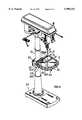
- FIG. 1is a perspective view of a drill press in which the table fence assembly is incorporated thereof
- FIG. 2is an exploded view of the table fence assembly made according to the present invention.
- FIG. 3is a schematic illustration of the table fence assembly shown in FIG. 2;
- FIG. 4is a schematic illustration of the drill press in which the workpiece is drilled by the help of the table fence assembly.
- the table fence assembly that is used to get an accurate drill on the workpiececan be readily mounted onto the table 2 of the drill press 20.
- the table 2is rotationally supported onto a column 21 of the drill press 20 and the table 2 can be moved left or right by the help of the table locking clamp 23.
- the table 2can be positioned at any position respect to the drill bit of the drill press 20 through the manipulation of the table locking clamp 23.
- the table 2is provided with a plurality of retaining grooves 24 that are similar to the conventional drill press 20.
- the table fence assembly 3made according to the present invention onto the table 2 via the retaining grooves 24. Accordingly, the machining such as drilling, boring and tapping can be accurately and efficiently performed by the help of the table fence assembly 3.
- the table fence assembly 3generally comprises a rear fence 31, a front fence 32 a plurality of locking bolts 33 and locking nuts 34.
- the rear fence 31has an L-shape cross section that includes a horizontal section 311 and a vertical section 313.
- the sections 311 and 313are each provided with an elongate hole 312 and 314 respectively.
- the front fence 32has also an L-shape cross section that defines a connecting section 321 and a supporting section 322.
- the supporting section 322is provided with opening 323 for applying a fastener thereof.
- the rear fence 31is firstly attached to the table 2 by the engagement between the elongate hole 312 of the horizontal section 311 and the elongate hole 24 of the table 2 by means of the locking bolts 33 and nuts 34.
- the front fence 32can be attached to the vertical section 313 of the rear fence 31 through the engagement between the opening 323 of the connecting section 321 and the elongate hole 314 of the vertical section 313 by means of the locking bolts 33 and nuts 34.
- a spannercan be used to tightly lock up the nuts 34 and the bolts 33.
- the front fence 32can be readily disposed at different position according different requirements from working procedures.
- FIG. 3has illustrated two feasible ways.
- the workpiece Wis firstly marked with a central point or pilot recess W1 through a puncher. Then the workpiece W can be disposed onto the table 2 in such a manner that the reference side or plane of the workpiece W is in contact with the vertical section 313 of the rear fence 31 and the supporting section 322 of the front fence 32. Then the tip D1 of the drill bit D can be lowered down to make sure whether the tip D is accurately aligned with the pilot recess W1 of the workpiece W.
- the table 2can be relocated respect to the column 22 by the help of the table locking clamp 23 till the tip D1 is completely aligned with the pilot recess W1 of the workpiece W. Then the drilling process can be commenced as shown in FIG. 4.
- the process of marking the pilot recess W1 on the workpiece Wcan be eliminated because once the workpiece W is held by the vertical section 313 and the supporting section 322, the drilling position on every workpiece W will be identical to each other.
- the reaction force on the workpiece Wcan be properly balanced and firmly held in position.
- the operatorwill not be injured by the over-reaction of the workpiece W.
- the table fence assembly 3the operator does not need to hold it on during the process. Even the workpiece W may become hot the hand of the operator will not be injured.
- the operatormay use his/her hand to spray cooling agent onto the drilling point to smooth the drilling.
- the table fence assembly 3is attached to the table 2 the retaining groove 24 can be selected such that it is located under the drill bit D1. As a result even the drill bit D1 passes through the workpiece W, the drill bit D1 will project through the retaining groove 24 and will not damage the top surface of the table 2.
Landscapes
- Engineering & Computer Science (AREA)
- Mechanical Engineering (AREA)
- Drilling And Boring (AREA)
Abstract
Description
The present invention relates to a table fence assembly, more particularly, to a table fence assembly of a drill press that is capable of facilitating accurate drilling on a workpiece. The table fence assembly can be installed onto a table of a drill press. The drill press includes a column in which the table is rotationally attached hereof through a table locking clamp for left or right adjustment thereof. The table includes a plurality of retaining grooves. The table fence comprises a rear fence having an L-shape cross section that defines a horizontal section and a vertical section. The sections are each provided with an elongate hole, respectively. Wherein the rear fence can be attached to the retaining grooves of the table by means of a plurality of locking bolts and nuts that pass through the elongate hole of the horizontal section and the retaining groove of the table. And a front fence that also has an L-shape cross section defining a connecting section and a supporting section. The supporting section is provided with an opening. Wherein the front fence can be attached to the vertical section of the rear fence by means of at least a locking bolt and nut that passes through the opening of the connecting section and the elongate hole of the vertical section of the rear fence. In drilling a bore on the workpiece the workpiece is firstly marked with a pilot recess by means of a puncher. Then the workpiece is disposed onto the table such that the referring plane of the workpiece is in contact with the vertical section of the rear fence and supporting section of the front fence. Then the tip of the drill bit is lowered down to make sure the tip of the drill bit is aligned with the pilot recess of the workpiece. If the tip of the drill bit is offset frown the pilot recess the table can be moved left or right by means of the table locking clamp till the tip of the drill bit is completely aligned with the pilot recess. Then the drilling process can be commenced By this arrangement, when another workpiece is to drill at the same location, the marking process for the pilot recess can be eliminated. When the workpiece is accurately supported by the vertical section of the rear fence and the supporting section of the front fence, the bore can be accurately and quickly drilled The safety of the operator can be also ensured
The drill press is basic machinery that can perform a machining process, such as drilling or boring, on a workpiece. Some drill press may even perform a tapping on the bore of the workpiece. The primary step of the machining process is to drill a pilot bore on the workpiece. Nevertheless, the accuracy of the position of the bore depends considerably on the fixture that is used to fixedly retain the workpiece. However, this bulky and complicate fixture is only for mass production. This is not suitable the drill press for home or personal use.
In order to drill a bore accurately, the central point or recess of the bore shall be firstly marked through a puncher that has a sharp tip. If this pilot point or recess is not accurately marked or offset from the intended position the post machining will also become inaccuracy. In worse condition, the whole workpiece will be discarded. This is a great loss on both labor hours and material.
On the other hand, when the drill bit drills a bore on the workpiece, a great rotational force will be imposed onto the workpiece. If this workpiece is not firmly held or only held manually, the workpiece will be moved from its original position and the whole drilling will be negatively effected. If this is the case, not only will the hand of the operator be possibly injured by the drill bit but also will the workpiece become defective as the bore is inaccurate. This will cause a loss on both labor hours and material. However, this is frequently happened to the conventional drill fence.
It is the object of this invention to provide a table fence assembly with which the drilling on a workpiece can be accurately performed.
In order to achieve the objective set forth, the table fence assembly for drill press of the type that can be installed onto a table of a drill press is provided. The drill press includes a column in which the table is rotationally attached thereof through a table locking clamp for left or right adjustment thereof. The table includes a plurality of retaining grooves. The table fence comprises a rear fence having an L-shape cross section that defines a horizontal section and a vertical section. The sections are each provided with an elongate hole, respectively. Wherein the rear fence can be attached to the retaining grooves of the table by means of a plurality of locking bolts and nuts that pass through the elongate hole of the horizontal section and the retaining groove of the table. And a front fence that also has an L-shape cross section defining a connecting section and a supporting section. The supporting section is provided with an opening. Wherein the front fence can be attached to the vertical section of the rear fence by means of at least a locking bolt and nut that passes through the opening of the connecting section and the elongate hole of the vertical section of the rear fence.
In drilling a bore on the workpiece the workpiece is firstly marked with a pilot recess by means of a puncher. Then the workpiece is disposed onto the table such that the referring plane of the workpiece is in contact with the vertical section of the rear fence and supporting section of the front fence. Then the tip of the drill bit is lowered down to make sure the tip of the drill bit is aligned with the pilot recess of the workpiece. If the tip of the drill bit is offset from the pilot recess, the table can be moved left or right by means of the table locking clamp till the tip of the drill bit is completely aligned with the pilot recess. Then the drilling process can be commenced By this arrangement, when another workpiece is to drill at the same location, the marking process for the pilot recess can be eliminated. When the workpiece is accurately supported by the vertical section of the rear fence and the supporting section of the front fence, the bore can be accurately and quickly drilled. The safety of the operator can be also ensured.
According to another aspect of the present invention by the provision of the vertical section of the rear fence and the supporting section of the front fence, the reaction force on the workpiece can be properly balanced and Only held in position. As a result, the operator will not be injured by the over-reaction of the aid workpiece. Furthermore as the workpiece is firmly held by the table fence assembly, the operator does not need to hold it on during the process. Even the workpiece may become hot, the hand of the operator will not be injured Besides, the operator may use his/her hand to spray cooling agent onto the drilling point to smooth the drilling. Besides, then the table fence assembly is attached to the table the retaining groove can be selected such that it is located under the drill bit As a result even the drill bit passes through the workpiece the drill bit will project through the retaining groove and will not damage the top surface of the table.
In order that the present invention may more readily be understood the following description is given, merely by way of example with reference to the accompanying drawings, in which:
FIG. 1 is a perspective view of a drill press in which the table fence assembly is incorporated thereof,
FIG. 2 is an exploded view of the table fence assembly made according to the present invention;
FIG. 3 is a schematic illustration of the table fence assembly shown in FIG. 2; and
FIG. 4 is a schematic illustration of the drill press in which the workpiece is drilled by the help of the table fence assembly.
Referring to FIGS. 1 and 2 the table fence assembly that is used to get an accurate drill on the workpiece can be readily mounted onto the table 2 of thedrill press 20. The table 2 is rotationally supported onto acolumn 21 of thedrill press 20 and the table 2 can be moved left or right by the help of thetable locking clamp 23. The table 2 can be positioned at any position respect to the drill bit of thedrill press 20 through the manipulation of thetable locking clamp 23. The table 2 is provided with a plurality of retaininggrooves 24 that are similar to theconventional drill press 20. Thetable fence assembly 3 made according to the present invention onto the table 2 via the retaininggrooves 24. Accordingly, the machining such as drilling, boring and tapping can be accurately and efficiently performed by the help of thetable fence assembly 3.
Thetable fence assembly 3 generally comprises arear fence 31, a front fence 32 a plurality of lockingbolts 33 and locking nuts 34. Therear fence 31 has an L-shape cross section that includes ahorizontal section 311 and avertical section 313. Thesections elongate hole front fence 32 has also an L-shape cross section that defines a connectingsection 321 and a supportingsection 322. The supportingsection 322 is provided withopening 323 for applying a fastener thereof.
In use therear fence 31 is firstly attached to the table 2 by the engagement between theelongate hole 312 of thehorizontal section 311 and theelongate hole 24 of the table 2 by means of the lockingbolts 33 and nuts 34. Then thefront fence 32 can be attached to thevertical section 313 of therear fence 31 through the engagement between the opening 323 of the connectingsection 321 and theelongate hole 314 of thevertical section 313 by means of the lockingbolts 33 and nuts 34. A spanner can be used to tightly lock up the nuts 34 and thebolts 33. Thefront fence 32 can be readily disposed at different position according different requirements from working procedures. FIG. 3 has illustrated two feasible ways.
In drilling a bore on a workpiece W. the workpiece W is firstly marked with a central point or pilot recess W1 through a puncher. Then the workpiece W can be disposed onto the table 2 in such a manner that the reference side or plane of the workpiece W is in contact with thevertical section 313 of therear fence 31 and the supportingsection 322 of thefront fence 32. Then the tip D1 of the drill bit D can be lowered down to make sure whether the tip D is accurately aligned with the pilot recess W1 of the workpiece W. If the tip D1 is not aligned with the pilot recess W1 then the table 2 can be relocated respect to thecolumn 22 by the help of thetable locking clamp 23 till the tip D1 is completely aligned with the pilot recess W1 of the workpiece W. Then the drilling process can be commenced as shown in FIG. 4. By this arrangement if a plurality of workpieces are to be drilled in the same position- the process of marking the pilot recess W1 on the workpiece W can be eliminated because once the workpiece W is held by thevertical section 313 and the supportingsection 322, the drilling position on every workpiece W will be identical to each other.
By the provision of thevertical section 313 and the supportingsection 322, the reaction force on the workpiece W can be properly balanced and firmly held in position. As a result, the operator will not be injured by the over-reaction of the workpiece W. Furthermore, as the workpiece W is firmly held by thetable fence assembly 3, the operator does not need to hold it on during the process. Even the workpiece W may become hot the hand of the operator will not be injured. Besides the operator may use his/her hand to spray cooling agent onto the drilling point to smooth the drilling. Besides then thetable fence assembly 3 is attached to the table 2 the retaininggroove 24 can be selected such that it is located under the drill bit D1. As a result even the drill bit D1 passes through the workpiece W, the drill bit D1 will project through the retaininggroove 24 and will not damage the top surface of the table 2.
While particular embodiment of the present invention has been illustrated and described it would be obvious to those skilled in the art that various other changes and modifications can be made without departing from the spirit and scope of the invention. It is therefore intended to cover in the appended claims all such changes and modifications that are within the scope of the present invention.
Claims (1)
1. A table fence assembly for a drill press of the type that can be installed onto the table of a drill press, said drill press including a column in which said table is rotationally attached thereto by means of a table locking clamp for left or right adjustment thereof, said table including a plurality of retaining grooves, comprising
a rear fence having an L-shape cross section that defines a horizontal section and a vertical sections said sections being each provided with an elongate hole, respectively, wherein said rear fence can be attached to said retaining grooves of said table by means of a plurality of locking bolts and nuts that pass through said elongate hole of said horizontal section and said retaining groove of said table; and
a front fence having also an L-shape cross section that defines a connecting section and a supporting section said supporting section being provided with at least one opening, wherein said front fence can be attached to said vertical section of said rear fence by means of at least one locking bolt and nut that pass through said at least one opening of said connecting section and said elongate hole of said vertical section of said rear fence.
Priority Applications (1)
| Application Number | Priority Date | Filing Date | Title |
|---|---|---|---|
| US09/054,512US5980167A (en) | 1998-04-03 | 1998-04-03 | Table fence assembly of drill press capable of facilitating accurate drilling on workpiece |
Applications Claiming Priority (1)
| Application Number | Priority Date | Filing Date | Title |
|---|---|---|---|
| US09/054,512US5980167A (en) | 1998-04-03 | 1998-04-03 | Table fence assembly of drill press capable of facilitating accurate drilling on workpiece |
Publications (1)
| Publication Number | Publication Date |
|---|---|
| US5980167Atrue US5980167A (en) | 1999-11-09 |
Family
ID=21991608
Family Applications (1)
| Application Number | Title | Priority Date | Filing Date |
|---|---|---|---|
| US09/054,512Expired - LifetimeUS5980167A (en) | 1998-04-03 | 1998-04-03 | Table fence assembly of drill press capable of facilitating accurate drilling on workpiece |
Country Status (1)
| Country | Link |
|---|---|
| US (1) | US5980167A (en) |
Cited By (24)
| Publication number | Priority date | Publication date | Assignee | Title |
|---|---|---|---|---|
| USD465501S1 (en) | 2001-07-23 | 2002-11-12 | Qingdao Daymaster Hardware & Tools, Co., Ltd. | Bench drill |
| US6494649B2 (en) | 2001-02-23 | 2002-12-17 | Juan C. Queipo | Table for a drill press |
| US20030228198A1 (en)* | 2002-06-10 | 2003-12-11 | Credo Tool Company | Drill press table accessory |
| US6705809B2 (en) | 2002-01-28 | 2004-03-16 | James T. Manos, Jr. | Drill press table |
| US20060039764A1 (en)* | 2003-01-08 | 2006-02-23 | George Moore | Drilling jig |
| US7004828B1 (en)* | 2004-12-03 | 2006-02-28 | Kenneth Picou | Sander apparatus and method |
| USD541318S1 (en)* | 2006-01-24 | 2007-04-24 | Black & Decker Inc. | Drill press |
| USD541319S1 (en)* | 2006-01-24 | 2007-04-24 | Black & Decker Inc. | Drill press |
| USD560696S1 (en) | 2006-10-04 | 2008-01-29 | Black & Decker Inc. | Drill press handle |
| US7413389B1 (en)* | 2003-12-15 | 2008-08-19 | Huebner Randall J | Adjustable calibrated pivot-arm stop |
| USD626155S1 (en)* | 2009-04-27 | 2010-10-26 | David Jebb | Bench drill |
| US8205865B1 (en)* | 2007-11-15 | 2012-06-26 | Textron Innovations Inc. | Universal jig tool |
| CN103639783A (en)* | 2013-12-02 | 2014-03-19 | 青岛地恩地机电科技股份有限公司 | Drill jig capable of being clamped in two faces |
| USD723075S1 (en)* | 2014-07-18 | 2015-02-24 | JPW Industries, Inc. | Drill press |
| USD732091S1 (en)* | 2014-04-21 | 2015-06-16 | Shanghai Sieg Machinery Co., Ltd. | Milling and drilling machine |
| CN104827081A (en)* | 2014-02-07 | 2015-08-12 | 力山工业股份有限公司 | Workpiece locating device of drilling machine |
| US20150283620A1 (en)* | 2014-04-02 | 2015-10-08 | Lee-Cheng Chang | Drill Press with Pivotable Table |
| CN107309689A (en)* | 2017-08-28 | 2017-11-03 | 含山县峰园精铸加工厂 | Drilling equipment |
| CN108044372A (en)* | 2017-12-13 | 2018-05-18 | 单杰 | Plate perforating mechanism, intelligent clamping device and application method |
| CN111002379A (en)* | 2019-12-23 | 2020-04-14 | 赵洁 | Bench drilling machine with positioning device |
| CN111015837A (en)* | 2019-12-30 | 2020-04-17 | 赵洁 | Vertical milling machine is used in panel furniture processing |
| WO2022077578A1 (en)* | 2020-10-15 | 2022-04-21 | 盐城丝路信息科技服务有限公司 | Board material high precision drilling apparatus for computer production |
| USD970562S1 (en)* | 2021-01-22 | 2022-11-22 | Scheppach Gmbh | Bench drilling machine |
| US11554516B2 (en)* | 2002-11-01 | 2023-01-17 | Black & Decker, Inc. | Tile saw |
Citations (6)
| Publication number | Priority date | Publication date | Assignee | Title |
|---|---|---|---|---|
| US2543917A (en)* | 1946-06-19 | 1951-03-06 | John T Lloyd | Machine for slotting venetian blind slats |
| US2747441A (en)* | 1953-08-28 | 1956-05-29 | Bernard G Johnson | Spot and bore machine |
| US3222052A (en)* | 1963-10-18 | 1965-12-07 | Freda Francis | Controllably adjustable mounting means |
| US5042542A (en)* | 1990-09-06 | 1991-08-27 | Purviance John R | Router table gauge |
| US5403129A (en)* | 1993-09-13 | 1995-04-04 | Steussy; Richard R. | Adjustable calibrated pivot-arm stop for drill-press work table |
| US5765273A (en)* | 1995-09-22 | 1998-06-16 | Black & Decker Inc. | Drill press having pivotable table |
- 1998
- 1998-04-03USUS09/054,512patent/US5980167A/ennot_activeExpired - Lifetime
Patent Citations (6)
| Publication number | Priority date | Publication date | Assignee | Title |
|---|---|---|---|---|
| US2543917A (en)* | 1946-06-19 | 1951-03-06 | John T Lloyd | Machine for slotting venetian blind slats |
| US2747441A (en)* | 1953-08-28 | 1956-05-29 | Bernard G Johnson | Spot and bore machine |
| US3222052A (en)* | 1963-10-18 | 1965-12-07 | Freda Francis | Controllably adjustable mounting means |
| US5042542A (en)* | 1990-09-06 | 1991-08-27 | Purviance John R | Router table gauge |
| US5403129A (en)* | 1993-09-13 | 1995-04-04 | Steussy; Richard R. | Adjustable calibrated pivot-arm stop for drill-press work table |
| US5765273A (en)* | 1995-09-22 | 1998-06-16 | Black & Decker Inc. | Drill press having pivotable table |
Cited By (29)
| Publication number | Priority date | Publication date | Assignee | Title |
|---|---|---|---|---|
| US6494649B2 (en) | 2001-02-23 | 2002-12-17 | Juan C. Queipo | Table for a drill press |
| USD465501S1 (en) | 2001-07-23 | 2002-11-12 | Qingdao Daymaster Hardware & Tools, Co., Ltd. | Bench drill |
| US6705809B2 (en) | 2002-01-28 | 2004-03-16 | James T. Manos, Jr. | Drill press table |
| US20030228198A1 (en)* | 2002-06-10 | 2003-12-11 | Credo Tool Company | Drill press table accessory |
| US6857829B2 (en) | 2002-06-10 | 2005-02-22 | Credo Technology Corporation | Drill press table accessory |
| US11554516B2 (en)* | 2002-11-01 | 2023-01-17 | Black & Decker, Inc. | Tile saw |
| US20060039764A1 (en)* | 2003-01-08 | 2006-02-23 | George Moore | Drilling jig |
| US7413389B1 (en)* | 2003-12-15 | 2008-08-19 | Huebner Randall J | Adjustable calibrated pivot-arm stop |
| US7004828B1 (en)* | 2004-12-03 | 2006-02-28 | Kenneth Picou | Sander apparatus and method |
| USD541319S1 (en)* | 2006-01-24 | 2007-04-24 | Black & Decker Inc. | Drill press |
| USD541318S1 (en)* | 2006-01-24 | 2007-04-24 | Black & Decker Inc. | Drill press |
| USD560696S1 (en) | 2006-10-04 | 2008-01-29 | Black & Decker Inc. | Drill press handle |
| US8205865B1 (en)* | 2007-11-15 | 2012-06-26 | Textron Innovations Inc. | Universal jig tool |
| USD626155S1 (en)* | 2009-04-27 | 2010-10-26 | David Jebb | Bench drill |
| CN103639783A (en)* | 2013-12-02 | 2014-03-19 | 青岛地恩地机电科技股份有限公司 | Drill jig capable of being clamped in two faces |
| CN104827081A (en)* | 2014-02-07 | 2015-08-12 | 力山工业股份有限公司 | Workpiece locating device of drilling machine |
| US20150283620A1 (en)* | 2014-04-02 | 2015-10-08 | Lee-Cheng Chang | Drill Press with Pivotable Table |
| USD732091S1 (en)* | 2014-04-21 | 2015-06-16 | Shanghai Sieg Machinery Co., Ltd. | Milling and drilling machine |
| USD723075S1 (en)* | 2014-07-18 | 2015-02-24 | JPW Industries, Inc. | Drill press |
| CN107309689A (en)* | 2017-08-28 | 2017-11-03 | 含山县峰园精铸加工厂 | Drilling equipment |
| CN107309689B (en)* | 2017-08-28 | 2024-01-23 | 含山县峰园精铸加工厂 | Drilling device |
| CN108044372A (en)* | 2017-12-13 | 2018-05-18 | 单杰 | Plate perforating mechanism, intelligent clamping device and application method |
| CN108044372B (en)* | 2017-12-13 | 2018-11-13 | 佛山联邦高登家私有限公司 | Plate perforating mechanism, intelligent clamping device and application method |
| CN111002379A (en)* | 2019-12-23 | 2020-04-14 | 赵洁 | Bench drilling machine with positioning device |
| CN111002379B (en)* | 2019-12-23 | 2021-10-26 | 嘉兴新博信息科技有限公司 | Bench drilling machine with positioning device |
| CN111015837A (en)* | 2019-12-30 | 2020-04-17 | 赵洁 | Vertical milling machine is used in panel furniture processing |
| WO2022077578A1 (en)* | 2020-10-15 | 2022-04-21 | 盐城丝路信息科技服务有限公司 | Board material high precision drilling apparatus for computer production |
| USD1012983S1 (en) | 2020-10-30 | 2024-01-30 | Scheppach Gmbh | Bench drilling machine |
| USD970562S1 (en)* | 2021-01-22 | 2022-11-22 | Scheppach Gmbh | Bench drilling machine |
Similar Documents
| Publication | Publication Date | Title |
|---|---|---|
| US5980167A (en) | Table fence assembly of drill press capable of facilitating accurate drilling on workpiece | |
| US5308199A (en) | Drill bit guiding device | |
| US6343632B1 (en) | Jig for fitting locks to doors | |
| US6557601B1 (en) | Mechanical stop system | |
| US4955766A (en) | Holding fixture for drilling pocket joints | |
| US6481937B1 (en) | Adjustable holding device | |
| US9969011B1 (en) | Vise fixture | |
| US20090309281A1 (en) | Method and fixture for handling and processing die components | |
| US20060228180A1 (en) | Adjustable holding systems and methods of using same | |
| US5367754A (en) | Gang tooling for a computerized numerically controlled lathe | |
| US4027992A (en) | Boring tool guide device | |
| Okpala et al. | The design and need for jigs and fixtures in manufacturing | |
| US20050089381A1 (en) | Wood-drilling apparatus | |
| US11376671B1 (en) | Method and apparatus for using a portable drill | |
| US4072439A (en) | Safety groove drill press and attachments | |
| CN102658491A (en) | Universal fence assembly having multi-position stop assemblies for power tool tables | |
| CN212977509U (en) | Radial drill's location frock | |
| US6240822B1 (en) | Adjustable precision indexing jig | |
| US5217331A (en) | Hardware installation tool | |
| US5486076A (en) | Radius-milling fixture for machining workpieces | |
| US5219376A (en) | Apparatus and method for mounting an EDM electrode | |
| US11485042B1 (en) | Fence and stop assembly system and method of use thereof | |
| US5996986A (en) | Vise stop | |
| US7252013B2 (en) | Brazed joint torque test apparatus and methods | |
| US3941364A (en) | Adjustable shaft rest assembly |
Legal Events
| Date | Code | Title | Description |
|---|---|---|---|
| STCF | Information on status: patent grant | Free format text:PATENTED CASE | |
| FPAY | Fee payment | Year of fee payment:4 | |
| FEPP | Fee payment procedure | Free format text:PAYOR NUMBER ASSIGNED (ORIGINAL EVENT CODE: ASPN); ENTITY STATUS OF PATENT OWNER: LARGE ENTITY | |
| AS | Assignment | Owner name:REXON INDUSTRIAL CORPORATION, LTD., TAIWAN Free format text:ASSIGNMENT OF ASSIGNORS INTEREST;ASSIGNOR:CHENG, MEI LING;REEL/FRAME:018597/0785 Effective date:20061206 | |
| FEPP | Fee payment procedure | Free format text:ENTITY STATUS SET TO UNDISCOUNTED (ORIGINAL EVENT CODE: BIG.); ENTITY STATUS OF PATENT OWNER: LARGE ENTITY | |
| FPAY | Fee payment | Year of fee payment:8 | |
| FEPP | Fee payment procedure | Free format text:PAYER NUMBER DE-ASSIGNED (ORIGINAL EVENT CODE: RMPN); ENTITY STATUS OF PATENT OWNER: LARGE ENTITY Free format text:PAYOR NUMBER ASSIGNED (ORIGINAL EVENT CODE: ASPN); ENTITY STATUS OF PATENT OWNER: LARGE ENTITY | |
| CC | Certificate of correction | ||
| CC | Certificate of correction | ||
| FPAY | Fee payment | Year of fee payment:12 |