US5980063A - Illuminated elongated tubular body - Google Patents
Illuminated elongated tubular bodyDownload PDFInfo
- Publication number
- US5980063A US5980063AUS08/937,021US93702197AUS5980063AUS 5980063 AUS5980063 AUS 5980063AUS 93702197 AUS93702197 AUS 93702197AUS 5980063 AUS5980063 AUS 5980063A
- Authority
- US
- United States
- Prior art keywords
- light
- tubular body
- refracting
- recited
- plastic material
- Prior art date
- Legal status (The legal status is an assumption and is not a legal conclusion. Google has not performed a legal analysis and makes no representation as to the accuracy of the status listed.)
- Expired - Lifetime
Links
- 239000000463materialSubstances0.000claimsabstractdescription22
- 229920003023plasticPolymers0.000claimsabstractdescription14
- 239000004033plasticSubstances0.000claimsabstractdescription12
- 239000002991molded plasticSubstances0.000claimsdescription6
- 238000002347injectionMethods0.000abstractdescription5
- 239000007924injectionSubstances0.000abstractdescription5
- XLYOFNOQVPJJNP-UHFFFAOYSA-NwaterSubstancesOXLYOFNOQVPJJNP-UHFFFAOYSA-N0.000description5
- 238000006243chemical reactionMethods0.000description1
- 239000012777electrically insulating materialSubstances0.000description1
- 239000000835fiberSubstances0.000description1
- 238000001746injection mouldingMethods0.000description1
- 238000004519manufacturing processMethods0.000description1
- 239000000126substanceSubstances0.000description1
Images

Classifications
- F—MECHANICAL ENGINEERING; LIGHTING; HEATING; WEAPONS; BLASTING
- F21—LIGHTING
- F21L—LIGHTING DEVICES OR SYSTEMS THEREOF, BEING PORTABLE OR SPECIALLY ADAPTED FOR TRANSPORTATION
- F21L4/00—Electric lighting devices with self-contained electric batteries or cells
Definitions
- the present inventionrelates to an improved lighting structure that is efficient enough to transmit light from a low power LED along the entire surface of an elongated tubular body.
- the present inventionis also concerned with the fabrication of such a tubular body by injection molding to provide for a water tight and impact resistant housing.
- light-refracting elementsare well known art. Typically designs have revolved around lenses using various prismatic, angular, or rounded engravings or projections and complemented by transparent or translucent materials to either highlight or diffuse light.
- the main object of the present inventionis to emit light along an elongated tube or cone.
- Another object of the inventionis to provide a lens member that is efficient both below and above water.
- a third object of the present inventionis to provide a lens member emitting light visible throughout a 180° hemisphere.
- Still further objects of the present inventioncomprise:
- a lens membercomprising an elongated tubular body made of light-propagating molded plastic material.
- This tubular bodycomprises an internal tapered surface formed with a generally helical thread.
- the helical threaddefines a light-refracting network for refracting and radiating light generally uniformly along the tubular body.
- the helical threadenables easy removal of the internal tapered surface of the tubular body from the mold surface by unscrewing, while producing adequate light refraction.
- a light stickcomprising an elongated tubular body made of light-propagating molded plastic material and including an internal tapered surface formed with a generally helical thread, and an end of larger diameter.
- the light stickalso comprises a light source mounted in the tubular body at the end of larger diameter.
- the helical threaddefines a light-refracting network for refracting and radiating light from the light source generally uniformly along the tubular body.
- the light-propagating plastic materialmay be transparent or translucent. When this plastic material is translucent, it can also be colored.
- the tubular bodyis tapered and has a generally uniform thickness
- the external surface of the tubular bodyis formed with a plurality of longitudinal light-refracting projections
- these longitudinal light-refracting projectionshave a generally triangular or arced cross section.
- the tubular bodyhas an end of smaller diameter, and this end of smaller diameter is closed;
- the end of larger diameter of the tubular bodyis externally threaded to receive an internally threaded end cap structured to receive at least one battery for supplying the light source;
- the light sourcecomprises a low power light-emitting diode
- the light stickfurther comprises switching means for selectively connecting the battery to the light source and disconnecting this battery from the light source.
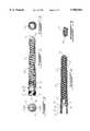
- FIG. 1is a side elevational view of a lens member according to the invention
- FIG. 2is an elevational view of an open end of the lens member of FIG. 1;
- FIG. 3is an elevational view of a closed end of the lens member of FIG. 1;
- FIG. 4is a cross sectional, side elevational view of the lens member of FIG. 1, taken along line 4--4 of FIG. 2;
- FIG. 5is a partial, elevational end view of longitudinal light-refracting projections formed on the external surface of the lens member of FIG. 1;
- FIG. 6is a side elevational view of a cap for closing the open end of the lens member of FIG. 1;
- FIG. 7is an elevational view of a closed end of the cap of FIG. 6;
- FIG. 8is an elevational view of an open end of the cap of FIG. 6.
- FIG. 9is a cross sectional, side elevational view of the cap of FIG. 6, taken along line 9--9 of FIG. 7.
- the preferred embodiment presented in the following descriptionis concerned with a light stick approximately six inch long.
- This light stickcomprises an electric light source 12, a lens member embodied by an elongated, slightly tapering tubular light-refracting body 13, and a cap 22.
- the tubular light-refracting body 13has a longitudinal axis 14 (FIG. 1) and is made of a translucent or transparent light-propagating material, preferably a translucent or transparent light-propagating plastic material moldable by injection.
- the translucent light-propagating plastic materialmay also be colored.
- the injection-molded body 13slightly tapers from a first open end 15 of larger diameter to a second closed end 16 of smaller diameter.
- the tubular body 13has a generally uniform thickness.
- the light source 12a low power light-emitting diode (LED) in the illustrated example, is mounted onto a circular support board 17 (FIG. 4) made of electrically insulating material.
- the board 17is fitted on an inner circular shoulder 18 formed in the open end 15 of the tubular body 13.
- the low power LED 12is aligned with the longitudinal axis 14 of the tubular body 13.
- a light-refracting (and also light-reflecting) network 19(FIG. 4) is formed on the internal tapered surface of the tubular body 13 to project light emitted by the LED 12 towards the sides and the closed end 16 of the tubular body 13.
- the network 19is constituted by a generally helical thread formed on the internal tapered surface of the tubular body 13.
- the light rays from the LED 12are refracted (and eventually also reflected) and radiated by the thread 19, and the translucent or transparent light-propagating material forming the tubular body 13 appears to glow evenly along its entire length.
- the threaded and tapered internal surface of the tubular body 13is particularly relevant and interesting since it allows easy disengagement of the tubular body 13 from the plastic injection mold by simple unscrewing and works efficiently as light-refracting surface with many different electric light sources.
- the external surface 20 of the tubular body 13may include a plurality of generally longitudinal light-refracting projections such as 21 (FIGS. 1 and 5) to improve the uniform light distribution along the tubular body 13.
- the projections 21may be arced or triangular in cross section as shown in FIG. 5.
- the external surface 26 (FIGS. 1 and 2) of the open end 15 of the tubular body 13has a threaded portion 24 to receive a threaded portion 23 (FIG. 9) of the internal surface 27 of the end cap 22.
- the end cap 22is provided to close and seal the open end 15 of the tubular body 13.
- the external surface 26 of the open end 15 of the tubular body 13has a non threaded portion 29 formed with at least one circular channel 28 (FIGS. 1 and 2) to receive an O-ring (not shown) made of suitable material to seal the space between the non threaded portion 29 of the tubular body 13 and a non threaded portion 30 of the internal surface 27 of the cap 22.
- the closed end of the cap 22is formed with an attachment loop member 31 to enable easy fastening of the light stick.
- the cap 22will contain the power source, namely at least one battery for supplying the LED 12, between the bottom 32 (FIG. 9) of the cap 22 and the board 17 (FIG. 4).
- the power sourcenamely at least one battery for supplying the LED 12, between the bottom 32 (FIG. 9) of the cap 22 and the board 17 (FIG. 4).
- a conductive switching circuitcan be designed and installed into the cap 22 (see 33 in FIG. 8) and the open end 15 of the tubular body 13 (see 34 and 35 in FIGS. 1 and 2) to enable turning on and turning off of the LED 12 by simply rotating the cap 22 with respect to the tubular body 13 about the longitudinal axis 14.
- the light stick according to the inventionpresents, amongst others, the following advantages:
- the light emitted from the tubular body 13is visible over a 180° hemisphere
- LEDswhich typically are pre-focused along a relatively narrow beam
- other applicationsmay comprise electrical source light wands of various sizes and configurations, and architectural and decorative lighting.
- non electrical light sourcessuch as light transmitted through chemical reactions, fiber optics and light-emitting phosphors, to improve both the volume and uniformity of the light output.
- the light-refracting tubular body in larger sizescan be used as an improved light wand attachment to flashlights, in series as and improvement to signage backlighting, and in similar or smaller form as an improvement to current light bulb lenses, particularly where LEDs are involved.
Landscapes
- Engineering & Computer Science (AREA)
- General Engineering & Computer Science (AREA)
- Non-Portable Lighting Devices Or Systems Thereof (AREA)
- Details Of Rigid Or Semi-Rigid Containers (AREA)
Abstract
Description
1. Field of the Invention
The present invention relates to an improved lighting structure that is efficient enough to transmit light from a low power LED along the entire surface of an elongated tubular body. The present invention is also concerned with the fabrication of such a tubular body by injection molding to provide for a water tight and impact resistant housing.
2. Brief Description of the Prior Art
The use of light-refracting elements is a well known art. Typically designs have revolved around lenses using various prismatic, angular, or rounded engravings or projections and complemented by transparent or translucent materials to either highlight or diffuse light.
Over the years many different versions of these lenses have appeared on a multitude of products ranging from light wands to automotive taillights and including common lighting fixtures. Numerous patents have been granted on these designs. Examples include the following U.S. patents:
______________________________________ 4,740,874 Wylie et al. 1988 5,519,593 Hasness 1996 5,339,225 Wiggerman 1994. ______________________________________
The main object of the present invention is to emit light along an elongated tube or cone.
Another object of the invention is to provide a lens member that is efficient both below and above water.
A third object of the present invention is to provide a lens member emitting light visible throughout a 180° hemisphere.
Still further objects of the present invention comprise:
a) providing a lens member capable of working with various light sources including electrical and other light sources;
b) providing a lens member capable of working with LED's which typically are pre-focused along a relatively narrow beam;
c) providing a lens member capable of being injection molded in a housing that can withstand significant impact and water pressure without breaking; and
d) providing a lens member having a design which enhances light sources and fixtures of various sizes and shapes.
More specifically, in accordance with the present invention, there is provided a lens member comprising an elongated tubular body made of light-propagating molded plastic material. This tubular body comprises an internal tapered surface formed with a generally helical thread. The helical thread defines a light-refracting network for refracting and radiating light generally uniformly along the tubular body.
The helical thread enables easy removal of the internal tapered surface of the tubular body from the mold surface by unscrewing, while producing adequate light refraction.
Also in accordance with the present invention, there is provided a light stick comprising an elongated tubular body made of light-propagating molded plastic material and including an internal tapered surface formed with a generally helical thread, and an end of larger diameter. The light stick also comprises a light source mounted in the tubular body at the end of larger diameter. The helical thread defines a light-refracting network for refracting and radiating light from the light source generally uniformly along the tubular body.
The light-propagating plastic material may be transparent or translucent. When this plastic material is translucent, it can also be colored.
In accordance with preferred embodiments, the tubular body is tapered and has a generally uniform thickness, the external surface of the tubular body is formed with a plurality of longitudinal light-refracting projections, and these longitudinal light-refracting projections have a generally triangular or arced cross section.
In accordance with a further preferred embodiment of the invention:
the tubular body has an end of smaller diameter, and this end of smaller diameter is closed;
the end of larger diameter of the tubular body is externally threaded to receive an internally threaded end cap structured to receive at least one battery for supplying the light source;
the light source comprises a low power light-emitting diode; and
the light stick further comprises switching means for selectively connecting the battery to the light source and disconnecting this battery from the light source.
The objects, advantages and other features of the present invention will become more apparent upon reading of the following non restrictive description of preferred embodiments thereof, given by way of example only with reference to the accompanying drawings.
In the appended drawings:
FIG. 1 is a side elevational view of a lens member according to the invention;
FIG. 2 is an elevational view of an open end of the lens member of FIG. 1;
FIG. 3 is an elevational view of a closed end of the lens member of FIG. 1;
FIG. 4 is a cross sectional, side elevational view of the lens member of FIG. 1, taken alongline 4--4 of FIG. 2;
FIG. 5 is a partial, elevational end view of longitudinal light-refracting projections formed on the external surface of the lens member of FIG. 1;
FIG. 6 is a side elevational view of a cap for closing the open end of the lens member of FIG. 1;
FIG. 7 is an elevational view of a closed end of the cap of FIG. 6;
FIG. 8 is an elevational view of an open end of the cap of FIG. 6; and
FIG. 9 is a cross sectional, side elevational view of the cap of FIG. 6, taken along line 9--9 of FIG. 7.
In the different figures of the appended drawings, the corresponding elements are identified by the same reference numerals.
The preferred embodiment presented in the following description is concerned with a light stick approximately six inch long.
This light stick comprises anelectric light source 12, a lens member embodied by an elongated, slightly tapering tubular light-refractingbody 13, and acap 22.
The tubular light-refractingbody 13 has a longitudinal axis 14 (FIG. 1) and is made of a translucent or transparent light-propagating material, preferably a translucent or transparent light-propagating plastic material moldable by injection. The translucent light-propagating plastic material may also be colored. The injection-moldedbody 13 slightly tapers from a first open end 15 of larger diameter to a second closedend 16 of smaller diameter. In the illustrated example, thetubular body 13 has a generally uniform thickness.
Thelight source 12, a low power light-emitting diode (LED) in the illustrated example, is mounted onto a circular support board 17 (FIG. 4) made of electrically insulating material. The board 17 is fitted on an innercircular shoulder 18 formed in the open end 15 of thetubular body 13. Thelow power LED 12 is aligned with thelongitudinal axis 14 of thetubular body 13.
A light-refracting (and also light-reflecting) network 19 (FIG. 4) is formed on the internal tapered surface of thetubular body 13 to project light emitted by theLED 12 towards the sides and the closedend 16 of thetubular body 13. Thenetwork 19 is constituted by a generally helical thread formed on the internal tapered surface of thetubular body 13. In operation, the light rays from theLED 12 are refracted (and eventually also reflected) and radiated by thethread 19, and the translucent or transparent light-propagating material forming thetubular body 13 appears to glow evenly along its entire length. The threaded and tapered internal surface of thetubular body 13 is particularly relevant and interesting since it allows easy disengagement of thetubular body 13 from the plastic injection mold by simple unscrewing and works efficiently as light-refracting surface with many different electric light sources.
Optionally, theexternal surface 20 of thetubular body 13 may include a plurality of generally longitudinal light-refracting projections such as 21 (FIGS. 1 and 5) to improve the uniform light distribution along thetubular body 13. Theprojections 21 may be arced or triangular in cross section as shown in FIG. 5.
The external surface 26 (FIGS. 1 and 2) of the open end 15 of thetubular body 13 has a threadedportion 24 to receive a threaded portion 23 (FIG. 9) of theinternal surface 27 of theend cap 22.
Theend cap 22 is provided to close and seal the open end 15 of thetubular body 13. For that purpose, theexternal surface 26 of the open end 15 of thetubular body 13 has a non threadedportion 29 formed with at least one circular channel 28 (FIGS. 1 and 2) to receive an O-ring (not shown) made of suitable material to seal the space between the non threadedportion 29 of thetubular body 13 and a non threadedportion 30 of theinternal surface 27 of thecap 22. The closed end of thecap 22 is formed with anattachment loop member 31 to enable easy fastening of the light stick.
Obviously, thecap 22 will contain the power source, namely at least one battery for supplying theLED 12, between the bottom 32 (FIG. 9) of thecap 22 and the board 17 (FIG. 4). Those of ordinary skill in the art will appreciate that a conductive switching circuit can be designed and installed into the cap 22 (see 33 in FIG. 8) and the open end 15 of the tubular body 13 (see 34 and 35 in FIGS. 1 and 2) to enable turning on and turning off of theLED 12 by simply rotating thecap 22 with respect to thetubular body 13 about thelongitudinal axis 14.
The light stick according to the invention presents, amongst others, the following advantages:
it can work underwater;
it is efficient both below and above water;
the light emitted from thetubular body 13 is visible over a 180° hemisphere;
it can work with various light sources including electric light sources and other types of light sources;
it can work with LEDs which typically are pre-focused along a relatively narrow beam;
it can be injection molded in a housing that could withstand significant water pressure without breaking; and
it enhances light sources and fixtures of widely varying sizes and shapes.
Although an approximately six inch long light stick is described as preferred embodiment in the present application, this stick using a low power LED to illuminate thetubular body 13 and being capable of competing in brightness, duration, and durability with chemical light sticks and other battery powered light sticks and beacons, it should be pointed out that the present invention is usable into many other applications, and hence, that the light stick application is not intended to restrict the use of the invention herein disclosed to this particular application.
For example, other applications may comprise electrical source light wands of various sizes and configurations, and architectural and decorative lighting.
It is also within the scope of the present invention to increase or reduce the dimensions of the elongated, tubular tapered light-refracting lens member described hereinabove to provide an efficient bulb lens for various light sources where the above mentioned qualities are desirable, in particular where at least a 180° field of vision is desirable. Personal and commercial light beacons, decorative and architectural light bulbs and fixtures, signage backlighting and various illuminated toys are contemplated, and many other applications exist.
It is further within the scope of the present invention to use non electrical light sources, such as light transmitted through chemical reactions, fiber optics and light-emitting phosphors, to improve both the volume and uniformity of the light output. It is also envisioned that the light-refracting tubular body in larger sizes can be used as an improved light wand attachment to flashlights, in series as and improvement to signage backlighting, and in similar or smaller form as an improvement to current light bulb lenses, particularly where LEDs are involved.
Although the present invention has been described hereinabove with reference to a preferred embodiment thereof, this embodiment can be modified at will, within the scope of the appended claims, without departing from the spirit and nature of the subject invention.
Claims (17)
1. A lens member comprising a one-piece elongated tubular body made of light-propagating molded plastic material, the tubular body comprising an internal tapered surface formed with a generally helical thread, wherein the helical thread defines a light-refracting network for refracting and radiating light generally uniformly along the tubular body.
2. A lens member as recited in claim 1, wherein said plastic material is transparent.
3. A lens member as recited in claim 1, wherein said plastic material is translucent.
4. A lens member as recited in claim 3, wherein said plastic material is colored.
5. A lens member as recited in claim 1, wherein the tubular body is an elongated, slightly tapering tubular body having a generally uniform thickness.
6. A light stick comprising:
a one-piece elongated tubular body made of light-propagating molded plastic material, including:
an internal tapered surface formed with a generally helical thread; and
an end of larger diameter;
a light source mounted in the tubular body at the end of larger diameter; and wherein the helical thread defines a light-refracting network for refracting and radiating light from the light source generally uniformly along the tubular body.
7. A light stick as recited in claim 6, wherein said plastic material is transparent.
8. A light stick as recited in claim 6, wherein said plastic material is translucent.
9. A light stick as recited in claim 8, wherein said plastic material is colored.
10. A light stick as recited in claim 6, wherein the tubular body is an elongated, slightly tapering tubular body having a generally uniform thickness.
11. A light stick as recited in claim 6, wherein the tubular body has an end of smaller diameter, and wherein said end of smaller diameter is closed.
12. A light stick as recited in claim 6, wherein the end of larger diameter of the tubular body is externally threaded to receive an internally threaded end cap structured to receive at least one battery for supplying the light source.
13. A light stick as recited in claim 12, wherein said light source comprises a low power light-emitting diode.
14. A light stick as recited in claim 12, further comprising switching means for selectively connecting said at least one battery to the light source and disconnecting said at least one battery from said light source.
15. A lens member comprising an elongated tubular body made of light-propagating molded plastic material, the tubular body comprising:
an internal tapered surface formed with a generally helical thread; and
an external surface formed with a plurality of longitudinal light-refracting projections; wherein the helical thread defines a light-refracting network for refracting and radiating light generally uniformly along the tubular body.
16. A light stick comprising:
an elongated tubular body made of light-propagating molded plastic material, including:
an internal tapered surface formed with a generally helical thread;
an external surface formed with a plurality of longitudinal light-refracting projections; and
an end of larger diameter; and
a light source mounted in the tubular body at the end of larger diameter;
wherein the helical thread defines a light-refracting network for refracting and radiating light from the light source generally uniformly along the tubular body.
17. A light stick as recited in claim 16, in which the longitudinal light-refracting projections have a generally triangular cross section.
Applications Claiming Priority (2)
| Application Number | Priority Date | Filing Date | Title |
|---|---|---|---|
| CA2194325 | 1997-01-03 | ||
| CA002194325ACA2194325C (en) | 1997-01-03 | 1997-01-03 | Illuminated elongated tube |
Publications (1)
| Publication Number | Publication Date |
|---|---|
| US5980063Atrue US5980063A (en) | 1999-11-09 |
Family
ID=4159593
Family Applications (1)
| Application Number | Title | Priority Date | Filing Date |
|---|---|---|---|
| US08/937,021Expired - LifetimeUS5980063A (en) | 1997-01-03 | 1997-09-24 | Illuminated elongated tubular body |
Country Status (2)
| Country | Link |
|---|---|
| US (1) | US5980063A (en) |
| CA (1) | CA2194325C (en) |
Cited By (53)
| Publication number | Priority date | Publication date | Assignee | Title |
|---|---|---|---|---|
| US6160948A (en)* | 1997-05-21 | 2000-12-12 | Mcgaffigan; Thomas H. | Optical light pipes with laser light appearance |
| USD445520S1 (en) | 2000-11-04 | 2001-07-24 | Tom C. Kaufman, Jr. | Railroad flashlight |
| US20030085642A1 (en)* | 2001-07-20 | 2003-05-08 | Pelka David G. | Fluorescent light source |
| US6603243B2 (en) | 2000-03-06 | 2003-08-05 | Teledyne Technologies Incorporated | LED light source with field-of-view-controlling optics |
| US6637924B2 (en)* | 2000-11-15 | 2003-10-28 | Teledyne Lighting And Display Products, Inc. | Strip lighting apparatus and method |
| US6672552B1 (en)* | 2003-05-02 | 2004-01-06 | Chzh-Lin Jao | Supporting rod assembly providing luminous decorating effect |
| US6724542B2 (en)* | 2000-01-07 | 2004-04-20 | Honeywell | Monolithic optical device for light transmission, and multi-channel optical system using same |
| US6744960B2 (en) | 2000-03-06 | 2004-06-01 | Teledyne Lighting And Display Products, Inc. | Lighting apparatus having quantum dot layer |
| US20040114386A1 (en)* | 2001-06-19 | 2004-06-17 | Hung Pao Chuan | Lighting structure of alarm lamp |
| US20040179372A1 (en)* | 2003-03-10 | 2004-09-16 | Salvatore Guerrieri | Light stick with LED light source |
| US20050018418A1 (en)* | 2003-07-25 | 2005-01-27 | Keith Darrell S. | Internally illuminated fishing rod |
| US20050094415A1 (en)* | 2003-10-29 | 2005-05-05 | Bor-Dong Cheng | Body molding for car |
| US20050135083A1 (en)* | 2003-12-23 | 2005-06-23 | Cindy Tait | Purse illumination assembly |
| US20050270801A1 (en)* | 2004-06-02 | 2005-12-08 | Torgerson David W | Light dispersion device |
| US20050282102A1 (en)* | 2004-06-16 | 2005-12-22 | Cms-Dental Aps | Kit for use by dental professionals |
| US20060070278A1 (en)* | 2004-08-03 | 2006-04-06 | Junichi Kajikuri | Laser irradiation system |
| US20060203478A1 (en)* | 2005-03-11 | 2006-09-14 | Michael Waters | Work light |
| US20060250802A1 (en)* | 2005-05-05 | 2006-11-09 | Herold Michael A | Interchangeable simulated neon light tube assemblies and related accessories for use with lighting devices |
| US20060250798A1 (en)* | 2005-05-05 | 2006-11-09 | Herold Michael A | Lighting device having a light tube with magnetically adjustable illumination |
| US20070041174A1 (en)* | 2004-04-27 | 2007-02-22 | Lo Teddy Y M | Led illuminated glow stick |
| US20070053203A1 (en)* | 2004-03-27 | 2007-03-08 | Morton Graham | Illumination device |
| US20070076409A1 (en)* | 2005-09-22 | 2007-04-05 | Mr B Innovations, Inc. | Durable illuminated stitching tools configured to provide ambient lighting and an illuminated working tip |
| WO2007048503A3 (en)* | 2005-10-26 | 2007-07-26 | Teddy Yeung Man Lo | Glow stick |
| USD547893S1 (en) | 2006-05-23 | 2007-07-31 | Vice Jeffrey L | Flashlight accessory |
| WO2007130126A1 (en)* | 2006-04-28 | 2007-11-15 | Eveready Battery Company, Inc. | Improved lens and lens arrangement |
| US7299865B1 (en) | 2004-09-01 | 2007-11-27 | Jason Kocher | Lift-out device for pitless well adapters |
| US20070273547A1 (en)* | 2006-05-18 | 2007-11-29 | Javier Lopez Barbarin | Signalling element |
| US20080130277A1 (en)* | 2005-03-11 | 2008-06-05 | Michael Waters | Work light |
| US20080277361A1 (en)* | 2007-05-07 | 2008-11-13 | The Coca-Cola Company | Dispenser with LED Lighting |
| US20090121654A1 (en)* | 2007-11-09 | 2009-05-14 | The Coca-Cola Company | LED Light Output Linearization |
| US20090244922A1 (en)* | 2008-03-28 | 2009-10-01 | Brother Kogyo Kabushiki Kaisha | Light pipe, illumination optical system and image projection device |
| US20090244884A1 (en)* | 2008-03-31 | 2009-10-01 | True Manufacturing Co. Inc. | Glass door merchandiser having led lights and mounting assembly therefor |
| US7625289B1 (en)* | 2006-05-31 | 2009-12-01 | John Fagliarone | Martial arts demonstration staff |
| US20100080017A1 (en)* | 2008-09-30 | 2010-04-01 | Microsoft Corporation | Uniformly lighting a cylindrical cavity via a prism |
| US20100085744A1 (en)* | 2008-10-02 | 2010-04-08 | Life+Gear, Inc. | Flashlight and illuminated rear section with two-sided lighting module |
| US20100110717A1 (en)* | 2008-11-03 | 2010-05-06 | Chien-Chung Chen | Assembled light-guiding module with high light-guiding efficiency |
| US20100148650A1 (en)* | 2008-12-17 | 2010-06-17 | Ping-Ju Wu | Structure of light bulb |
| US20100157582A1 (en)* | 2008-10-02 | 2010-06-24 | Life+Gear, Inc. | Multipurpose waterproof lighting device with electronic glow stick |
| USRE41876E1 (en)* | 2000-06-21 | 2010-10-26 | Po-Hua Fang | Light source mechanism for an imaging apparatus |
| US20110044034A1 (en)* | 2008-10-02 | 2011-02-24 | Life+Gear, Inc. | Multipurpose lighting device with electronic glow stick |
| US20110216533A1 (en)* | 2010-03-02 | 2011-09-08 | Life+Gear, Inc. | Electronic glow stick device with alternating flasher |
| US20140230309A1 (en)* | 2013-02-21 | 2014-08-21 | Nautical Illuminations, LLC | Illuminating outrigger tip |
| USD725816S1 (en)* | 2012-08-10 | 2015-03-31 | Jeremy J. Fissell | Transparent tapered open-ended slip-cover surrounding an illuminating baton |
| USD725815S1 (en)* | 2012-08-10 | 2015-03-31 | Jeremy J. Fissell | Transparent tapered slip cover holding a rolled flyer surrounding an illuminating baton |
| US9115865B1 (en)* | 2012-06-19 | 2015-08-25 | Forever Gifts, Inc. | Lighting device having light-distributing void |
| US20160258579A1 (en)* | 2015-03-02 | 2016-09-08 | Buster And Punch Limited | Light Bulb |
| US11409031B2 (en) | 2020-03-02 | 2022-08-09 | Stmicroelectronics (Grenoble 2) Sas | Optical device |
| USD979104S1 (en) | 2020-02-28 | 2023-02-21 | Buster And Punch Limited | Light fitting |
| USD981631S1 (en) | 2020-01-30 | 2023-03-21 | Buster And Punch Limited | Light fixture |
| USD987860S1 (en) | 2021-02-25 | 2023-05-30 | Buster And Punch Limited | Light bulb |
| USD987859S1 (en) | 2021-02-25 | 2023-05-30 | Buster And Punch Limited | Light bulb |
| USD1091919S1 (en) | 2017-03-13 | 2025-09-02 | Buster And Punch Limited | Light fixture |
| US20250280930A1 (en)* | 2024-03-11 | 2025-09-11 | Rozilyn Renee Storey | Lighted Walking Stick |
Families Citing this family (2)
| Publication number | Priority date | Publication date | Assignee | Title |
|---|---|---|---|---|
| CA3004436C (en) | 2018-05-09 | 2021-06-01 | Paige Whitehead | Biodegradable light wand |
| WO2023028688A1 (en) | 2021-09-01 | 2023-03-09 | Nyoka Design Corp. | Reusable photoluminescent apparatus, methods, and systems |
Citations (23)
| Publication number | Priority date | Publication date | Assignee | Title |
|---|---|---|---|---|
| US2225151A (en)* | 1939-09-16 | 1940-12-17 | Edward J Borba | Illuminated baton |
| US2245349A (en)* | 1939-07-27 | 1941-06-10 | Frank P Lombardl | Illuminating cane |
| US2486998A (en)* | 1948-06-19 | 1949-11-01 | Harry J Szeklinski | Safety flashlight with interchangeably mounted sheath |
| US3576987A (en)* | 1968-11-07 | 1971-05-04 | American Cyanamid Co | Chemical lighting device to store, initiate and display chemical light |
| US4064428A (en)* | 1976-11-01 | 1977-12-20 | American Cyanamid Company | Chemical light device |
| US4175661A (en)* | 1978-08-28 | 1979-11-27 | Lexalite International Corporation | Stackable light refractor |
| US4181928A (en)* | 1977-12-22 | 1980-01-01 | Lighting Systems, Inc. | Portable spot/flood light |
| US4508642A (en)* | 1983-04-21 | 1985-04-02 | World Victor B | Method of obtaining greater lifetime duration from chemiluminescent systems |
| US4740874A (en)* | 1985-12-05 | 1988-04-26 | Wylie Bruce E | Wylie-lite |
| US4967321A (en)* | 1988-11-14 | 1990-10-30 | I & K Trading Company | Flashlight wand |
| US5079679A (en)* | 1990-08-27 | 1992-01-07 | Chin Fa Yen | Multi-purpose traffic director's stick |
| US5152598A (en)* | 1990-10-24 | 1992-10-06 | Schaffer Garry D | Hole locator device |
| US5158349A (en)* | 1991-07-03 | 1992-10-27 | Lexington & Associates, Inc. | Multi-color chemical lighting device |
| USD331889S (en) | 1990-07-11 | 1992-12-22 | Chemical Device Corporation | Chemiluminescent light stick |
| US5213405A (en)* | 1991-09-13 | 1993-05-25 | American Cyanamid Company | Lightstick with line attachment means |
| US5339225A (en)* | 1993-02-08 | 1994-08-16 | Ron Wiggerman | Illuminated wand |
| US5383103A (en)* | 1993-09-21 | 1995-01-17 | Pasch; Ricky C. | Flashlight wand attachment |
| USD356276S (en) | 1993-09-22 | 1995-03-14 | Kai Gee Enterprise Co., Ltd. | Night chemical illuminant torch |
| US5444606A (en)* | 1994-02-10 | 1995-08-22 | Lexalite International Corporation | Prismatic reflector and prismatic lens |
| USD368045S (en) | 1995-01-24 | 1996-03-19 | Akers Laboratories Inc. | Chemiluminescent light stick |
| US5519593A (en)* | 1994-02-14 | 1996-05-21 | Walterscott International Corp. | Method and apparatus for handling a lightwand |
| USD370276S (en) | 1995-03-06 | 1996-05-28 | Davis Ronald O | Lighted baton |
| US5690414A (en)* | 1996-12-03 | 1997-11-25 | Jeng; Jong-Pyng | Screw driver adapted for use as a signaling device |
- 1997
- 1997-01-03CACA002194325Apatent/CA2194325C/ennot_activeExpired - Fee Related
- 1997-09-24USUS08/937,021patent/US5980063A/ennot_activeExpired - Lifetime
Patent Citations (23)
| Publication number | Priority date | Publication date | Assignee | Title |
|---|---|---|---|---|
| US2245349A (en)* | 1939-07-27 | 1941-06-10 | Frank P Lombardl | Illuminating cane |
| US2225151A (en)* | 1939-09-16 | 1940-12-17 | Edward J Borba | Illuminated baton |
| US2486998A (en)* | 1948-06-19 | 1949-11-01 | Harry J Szeklinski | Safety flashlight with interchangeably mounted sheath |
| US3576987A (en)* | 1968-11-07 | 1971-05-04 | American Cyanamid Co | Chemical lighting device to store, initiate and display chemical light |
| US4064428A (en)* | 1976-11-01 | 1977-12-20 | American Cyanamid Company | Chemical light device |
| US4181928A (en)* | 1977-12-22 | 1980-01-01 | Lighting Systems, Inc. | Portable spot/flood light |
| US4175661A (en)* | 1978-08-28 | 1979-11-27 | Lexalite International Corporation | Stackable light refractor |
| US4508642A (en)* | 1983-04-21 | 1985-04-02 | World Victor B | Method of obtaining greater lifetime duration from chemiluminescent systems |
| US4740874A (en)* | 1985-12-05 | 1988-04-26 | Wylie Bruce E | Wylie-lite |
| US4967321A (en)* | 1988-11-14 | 1990-10-30 | I & K Trading Company | Flashlight wand |
| USD331889S (en) | 1990-07-11 | 1992-12-22 | Chemical Device Corporation | Chemiluminescent light stick |
| US5079679A (en)* | 1990-08-27 | 1992-01-07 | Chin Fa Yen | Multi-purpose traffic director's stick |
| US5152598A (en)* | 1990-10-24 | 1992-10-06 | Schaffer Garry D | Hole locator device |
| US5158349A (en)* | 1991-07-03 | 1992-10-27 | Lexington & Associates, Inc. | Multi-color chemical lighting device |
| US5213405A (en)* | 1991-09-13 | 1993-05-25 | American Cyanamid Company | Lightstick with line attachment means |
| US5339225A (en)* | 1993-02-08 | 1994-08-16 | Ron Wiggerman | Illuminated wand |
| US5383103A (en)* | 1993-09-21 | 1995-01-17 | Pasch; Ricky C. | Flashlight wand attachment |
| USD356276S (en) | 1993-09-22 | 1995-03-14 | Kai Gee Enterprise Co., Ltd. | Night chemical illuminant torch |
| US5444606A (en)* | 1994-02-10 | 1995-08-22 | Lexalite International Corporation | Prismatic reflector and prismatic lens |
| US5519593A (en)* | 1994-02-14 | 1996-05-21 | Walterscott International Corp. | Method and apparatus for handling a lightwand |
| USD368045S (en) | 1995-01-24 | 1996-03-19 | Akers Laboratories Inc. | Chemiluminescent light stick |
| USD370276S (en) | 1995-03-06 | 1996-05-28 | Davis Ronald O | Lighted baton |
| US5690414A (en)* | 1996-12-03 | 1997-11-25 | Jeng; Jong-Pyng | Screw driver adapted for use as a signaling device |
Cited By (84)
| Publication number | Priority date | Publication date | Assignee | Title |
|---|---|---|---|---|
| US6160948A (en)* | 1997-05-21 | 2000-12-12 | Mcgaffigan; Thomas H. | Optical light pipes with laser light appearance |
| US6337946B1 (en) | 1997-05-21 | 2002-01-08 | Mcgaffigan Thomas H. | Optical light pipes with laser light appearance |
| US6724542B2 (en)* | 2000-01-07 | 2004-04-20 | Honeywell | Monolithic optical device for light transmission, and multi-channel optical system using same |
| US6744960B2 (en) | 2000-03-06 | 2004-06-01 | Teledyne Lighting And Display Products, Inc. | Lighting apparatus having quantum dot layer |
| US6603243B2 (en) | 2000-03-06 | 2003-08-05 | Teledyne Technologies Incorporated | LED light source with field-of-view-controlling optics |
| USRE41876E1 (en)* | 2000-06-21 | 2010-10-26 | Po-Hua Fang | Light source mechanism for an imaging apparatus |
| USD445520S1 (en) | 2000-11-04 | 2001-07-24 | Tom C. Kaufman, Jr. | Railroad flashlight |
| US6637924B2 (en)* | 2000-11-15 | 2003-10-28 | Teledyne Lighting And Display Products, Inc. | Strip lighting apparatus and method |
| US20040114386A1 (en)* | 2001-06-19 | 2004-06-17 | Hung Pao Chuan | Lighting structure of alarm lamp |
| US6784603B2 (en) | 2001-07-20 | 2004-08-31 | Teledyne Lighting And Display Products, Inc. | Fluorescent lighting apparatus |
| US20030085642A1 (en)* | 2001-07-20 | 2003-05-08 | Pelka David G. | Fluorescent light source |
| US20040179372A1 (en)* | 2003-03-10 | 2004-09-16 | Salvatore Guerrieri | Light stick with LED light source |
| US6857771B2 (en)* | 2003-03-10 | 2005-02-22 | Acolyte Technologies Llc. | Light stick with LED light source |
| US6672552B1 (en)* | 2003-05-02 | 2004-01-06 | Chzh-Lin Jao | Supporting rod assembly providing luminous decorating effect |
| US20050018418A1 (en)* | 2003-07-25 | 2005-01-27 | Keith Darrell S. | Internally illuminated fishing rod |
| US20050094415A1 (en)* | 2003-10-29 | 2005-05-05 | Bor-Dong Cheng | Body molding for car |
| US7207689B2 (en)* | 2003-12-23 | 2007-04-24 | Cindy Tait | Touch activated purse illumination assembly |
| US20050135083A1 (en)* | 2003-12-23 | 2005-06-23 | Cindy Tait | Purse illumination assembly |
| US20070053203A1 (en)* | 2004-03-27 | 2007-03-08 | Morton Graham | Illumination device |
| US7293903B2 (en) | 2004-04-27 | 2007-11-13 | Teddy Yeung Man Lo | LED illuminated glow stick |
| US7566157B2 (en) | 2004-04-27 | 2009-07-28 | Teddy Yeung Man Lo | Fiber optics illuminated glow stick |
| US20070041174A1 (en)* | 2004-04-27 | 2007-02-22 | Lo Teddy Y M | Led illuminated glow stick |
| US7134765B2 (en)* | 2004-06-02 | 2006-11-14 | Torgerson David W | Light dispersion device |
| US20050270801A1 (en)* | 2004-06-02 | 2005-12-08 | Torgerson David W | Light dispersion device |
| US20050282102A1 (en)* | 2004-06-16 | 2005-12-22 | Cms-Dental Aps | Kit for use by dental professionals |
| US7578602B2 (en)* | 2004-08-03 | 2009-08-25 | Sony Corporation | Laser irradiation system |
| US20060070278A1 (en)* | 2004-08-03 | 2006-04-06 | Junichi Kajikuri | Laser irradiation system |
| US7299865B1 (en) | 2004-09-01 | 2007-11-27 | Jason Kocher | Lift-out device for pitless well adapters |
| US20100238654A1 (en)* | 2005-03-11 | 2010-09-23 | Panther Vision, Llc | Work Light |
| US7703966B2 (en) | 2005-03-11 | 2010-04-27 | Panther Vision, Llc | Work light |
| US20060203478A1 (en)* | 2005-03-11 | 2006-09-14 | Michael Waters | Work light |
| US7306349B2 (en)* | 2005-03-11 | 2007-12-11 | Michael Waters | Work light |
| US20080130277A1 (en)* | 2005-03-11 | 2008-06-05 | Michael Waters | Work light |
| US7293891B2 (en) | 2005-05-05 | 2007-11-13 | Herold Design Group Llc | Lighting device having a light tube with magnetically adjustable illumination |
| US20060250798A1 (en)* | 2005-05-05 | 2006-11-09 | Herold Michael A | Lighting device having a light tube with magnetically adjustable illumination |
| US20060250802A1 (en)* | 2005-05-05 | 2006-11-09 | Herold Michael A | Interchangeable simulated neon light tube assemblies and related accessories for use with lighting devices |
| US20070076409A1 (en)* | 2005-09-22 | 2007-04-05 | Mr B Innovations, Inc. | Durable illuminated stitching tools configured to provide ambient lighting and an illuminated working tip |
| WO2007048503A3 (en)* | 2005-10-26 | 2007-07-26 | Teddy Yeung Man Lo | Glow stick |
| CN101300510B (en)* | 2005-10-26 | 2014-10-08 | 罗扬文 | Luminous stick |
| WO2007130126A1 (en)* | 2006-04-28 | 2007-11-15 | Eveready Battery Company, Inc. | Improved lens and lens arrangement |
| US20070273547A1 (en)* | 2006-05-18 | 2007-11-29 | Javier Lopez Barbarin | Signalling element |
| US7652588B2 (en)* | 2006-05-18 | 2010-01-26 | Barbolight, S.L. | Signalling element |
| USD547893S1 (en) | 2006-05-23 | 2007-07-31 | Vice Jeffrey L | Flashlight accessory |
| US7625289B1 (en)* | 2006-05-31 | 2009-12-01 | John Fagliarone | Martial arts demonstration staff |
| US20080277361A1 (en)* | 2007-05-07 | 2008-11-13 | The Coca-Cola Company | Dispenser with LED Lighting |
| US7586274B2 (en) | 2007-11-09 | 2009-09-08 | The Coca-Cola Company | LED light output linearization |
| US20090121654A1 (en)* | 2007-11-09 | 2009-05-14 | The Coca-Cola Company | LED Light Output Linearization |
| US20090289576A1 (en)* | 2007-11-09 | 2009-11-26 | The Coca-Cola Company | Led light output linearization |
| US8013541B2 (en) | 2007-11-09 | 2011-09-06 | The Coca-Cola Company | LED light output linearization |
| US20090244922A1 (en)* | 2008-03-28 | 2009-10-01 | Brother Kogyo Kabushiki Kaisha | Light pipe, illumination optical system and image projection device |
| US20090244884A1 (en)* | 2008-03-31 | 2009-10-01 | True Manufacturing Co. Inc. | Glass door merchandiser having led lights and mounting assembly therefor |
| US20100080017A1 (en)* | 2008-09-30 | 2010-04-01 | Microsoft Corporation | Uniformly lighting a cylindrical cavity via a prism |
| US8118463B2 (en)* | 2008-09-30 | 2012-02-21 | Microsoft Corporation | Uniformly lighting a cylindrical cavity via a prism |
| US8186846B2 (en) | 2008-10-02 | 2012-05-29 | Life+Gear, Inc. | Multipurpose lighting device with electronic glow stick |
| US20110044034A1 (en)* | 2008-10-02 | 2011-02-24 | Life+Gear, Inc. | Multipurpose lighting device with electronic glow stick |
| US20100085744A1 (en)* | 2008-10-02 | 2010-04-08 | Life+Gear, Inc. | Flashlight and illuminated rear section with two-sided lighting module |
| US8545040B2 (en) | 2008-10-02 | 2013-10-01 | Life+Gear, Inc. | Flashlight and illuminated rear section with two-sided lighting module |
| US8113682B2 (en) | 2008-10-02 | 2012-02-14 | Life+Gear, Inc. | Multipurpose waterproof lighting device with electronic glow stick |
| US20100157582A1 (en)* | 2008-10-02 | 2010-06-24 | Life+Gear, Inc. | Multipurpose waterproof lighting device with electronic glow stick |
| US8529087B2 (en) | 2008-10-02 | 2013-09-10 | Square 1 Bank | Multipurpose lighting device with electronic glow stick |
| US8360596B2 (en) | 2008-10-02 | 2013-01-29 | Life+Gear, Inc. | Flashlight and illuminated rear section with two-sided lighting module |
| US20100110717A1 (en)* | 2008-11-03 | 2010-05-06 | Chien-Chung Chen | Assembled light-guiding module with high light-guiding efficiency |
| US8303149B2 (en)* | 2008-11-03 | 2012-11-06 | Chien-Chung Chen | Assembled light-guiding module with high light-guiding efficiency |
| TWI392902B (en)* | 2008-11-03 | 2013-04-11 | Assembled light-guiding with high light-guiding efficiency | |
| US7976206B2 (en)* | 2008-12-17 | 2011-07-12 | U-How Co., Ltd. | Structure of light bulb |
| US20100148650A1 (en)* | 2008-12-17 | 2010-06-17 | Ping-Ju Wu | Structure of light bulb |
| WO2011109429A1 (en)* | 2010-03-02 | 2011-09-09 | Life+ Gear, Inc. | Electronic glow stick device with alternating flasher |
| US20110216533A1 (en)* | 2010-03-02 | 2011-09-08 | Life+Gear, Inc. | Electronic glow stick device with alternating flasher |
| WO2011109431A1 (en)* | 2010-03-02 | 2011-09-09 | Life+Gear, Inc. | Multipurpose waterproof lighting device with electronic glow stick |
| US9115865B1 (en)* | 2012-06-19 | 2015-08-25 | Forever Gifts, Inc. | Lighting device having light-distributing void |
| USD725816S1 (en)* | 2012-08-10 | 2015-03-31 | Jeremy J. Fissell | Transparent tapered open-ended slip-cover surrounding an illuminating baton |
| USD725815S1 (en)* | 2012-08-10 | 2015-03-31 | Jeremy J. Fissell | Transparent tapered slip cover holding a rolled flyer surrounding an illuminating baton |
| US20170325438A1 (en)* | 2013-02-21 | 2017-11-16 | Nautical Illuminations, LLC | Illuminating outrigger tip |
| US20140230309A1 (en)* | 2013-02-21 | 2014-08-21 | Nautical Illuminations, LLC | Illuminating outrigger tip |
| US10365421B2 (en)* | 2015-03-02 | 2019-07-30 | Buster And Punch Limited | Lighting device with light pipe enclosed within a bulb and having colored lines |
| US20160258579A1 (en)* | 2015-03-02 | 2016-09-08 | Buster And Punch Limited | Light Bulb |
| USD1091919S1 (en) | 2017-03-13 | 2025-09-02 | Buster And Punch Limited | Light fixture |
| USD981631S1 (en) | 2020-01-30 | 2023-03-21 | Buster And Punch Limited | Light fixture |
| USD979104S1 (en) | 2020-02-28 | 2023-02-21 | Buster And Punch Limited | Light fitting |
| US11409031B2 (en) | 2020-03-02 | 2022-08-09 | Stmicroelectronics (Grenoble 2) Sas | Optical device |
| TWI775334B (en)* | 2020-03-02 | 2022-08-21 | 英商意法半導體(R&D)有限公司 | Optical device |
| USD987860S1 (en) | 2021-02-25 | 2023-05-30 | Buster And Punch Limited | Light bulb |
| USD987859S1 (en) | 2021-02-25 | 2023-05-30 | Buster And Punch Limited | Light bulb |
| US20250280930A1 (en)* | 2024-03-11 | 2025-09-11 | Rozilyn Renee Storey | Lighted Walking Stick |
Also Published As
| Publication number | Publication date |
|---|---|
| CA2194325A1 (en) | 1998-07-03 |
| CA2194325C (en) | 2007-11-06 |
Similar Documents
| Publication | Publication Date | Title |
|---|---|---|
| US5980063A (en) | Illuminated elongated tubular body | |
| US6857771B2 (en) | Light stick with LED light source | |
| US6361192B1 (en) | Lens system for enhancing LED light output | |
| US7387402B1 (en) | Multiple light LED flashlight | |
| US7976206B2 (en) | Structure of light bulb | |
| US6550940B2 (en) | Lighting device | |
| US10876693B2 (en) | Downlight apparatus | |
| US20040027837A1 (en) | Optical fiber light | |
| EP1634335A4 (en) | OPTICAL APPARATUS FOR ELECTRIC LAMP SUBSTITUTE BASED ON LIGHT EMITTING DIODES | |
| US20060250802A1 (en) | Interchangeable simulated neon light tube assemblies and related accessories for use with lighting devices | |
| JP2011238609A (en) | Lighting device | |
| US20050157487A1 (en) | Submersible light source for an optical fiber flower display in a water-filled vase | |
| CN1209569C (en) | Lamp for use in living room, especially table or floor lamp | |
| US20060268548A1 (en) | LED lighting device with light converging effect | |
| CN107588337A (en) | Light distribution lens and LED lamp using the lens | |
| KR100790046B1 (en) | Double sided diffusion light emitting device | |
| CN102261578A (en) | Omnibearing three-dimensional quantizing light emitting device | |
| CN201273478Y (en) | LED illuminating device | |
| JP5125437B2 (en) | Illumination body | |
| CN211694511U (en) | Logistics terminal | |
| EP2390553A2 (en) | LED illuminating apparatus | |
| US7753540B2 (en) | Illuminable indicator and light engine therefor | |
| KR102159785B1 (en) | fishing light for the long-line fishery | |
| CN210424721U (en) | Optical cover and down lamp applying same | |
| WO2010044192A1 (en) | Led light bulb |
Legal Events
| Date | Code | Title | Description |
|---|---|---|---|
| STCF | Information on status: patent grant | Free format text:PATENTED CASE | |
| FPAY | Fee payment | Year of fee payment:4 | |
| AS | Assignment | Owner name:THE FLEWELLING FORD FAMILY TRUST, QUEBEC Free format text:ASSIGNMENT OF ASSIGNORS INTEREST;ASSIGNOR:FORD, TIMOTHY D.F.;REEL/FRAME:018866/0806 Effective date:20070122 Owner name:FORD, TIMOTHY D.F., QUEBEC Free format text:ASSIGNMENT OF ASSIGNORS INTEREST;ASSIGNOR:COTE, MICHEL S.;REEL/FRAME:018866/0799 Effective date:20020125 | |
| FPAY | Fee payment | Year of fee payment:8 | |
| FPAY | Fee payment | Year of fee payment:12 | |
| AS | Assignment | Owner name:9609385 CANADA INC., CANADA Free format text:NUNC PRO TUNC ASSIGNMENT;ASSIGNOR:THE FLEWELLING FORD FAMILY TRUST;REEL/FRAME:040039/0081 Effective date:20160927 |