US5979761A - Bar code laser scanner having a plurality of adjustable mirrors - Google Patents
Bar code laser scanner having a plurality of adjustable mirrorsDownload PDFInfo
- Publication number
- US5979761A US5979761AUS08/970,726US97072697AUS5979761AUS 5979761 AUS5979761 AUS 5979761AUS 97072697 AUS97072697 AUS 97072697AUS 5979761 AUS5979761 AUS 5979761A
- Authority
- US
- United States
- Prior art keywords
- scanner
- adjustable
- scanning
- mirror
- mirror assemblies
- Prior art date
- Legal status (The legal status is an assumption and is not a legal conclusion. Google has not performed a legal analysis and makes no representation as to the accuracy of the status listed.)
- Expired - Lifetime
Links
Images


Classifications
- G—PHYSICS
- G06—COMPUTING OR CALCULATING; COUNTING
- G06K—GRAPHICAL DATA READING; PRESENTATION OF DATA; RECORD CARRIERS; HANDLING RECORD CARRIERS
- G06K7/00—Methods or arrangements for sensing record carriers, e.g. for reading patterns
- G06K7/10—Methods or arrangements for sensing record carriers, e.g. for reading patterns by electromagnetic radiation, e.g. optical sensing; by corpuscular radiation
- G06K7/10544—Methods or arrangements for sensing record carriers, e.g. for reading patterns by electromagnetic radiation, e.g. optical sensing; by corpuscular radiation by scanning of the records by radiation in the optical part of the electromagnetic spectrum
- G06K7/10554—Moving beam scanning
- G06K7/10594—Beam path
- G06K7/10683—Arrangement of fixed elements
- G06K7/10702—Particularities of propagating elements, e.g. lenses, mirrors
- G—PHYSICS
- G06—COMPUTING OR CALCULATING; COUNTING
- G06K—GRAPHICAL DATA READING; PRESENTATION OF DATA; RECORD CARRIERS; HANDLING RECORD CARRIERS
- G06K7/00—Methods or arrangements for sensing record carriers, e.g. for reading patterns
- G06K7/10—Methods or arrangements for sensing record carriers, e.g. for reading patterns by electromagnetic radiation, e.g. optical sensing; by corpuscular radiation
- G06K7/10544—Methods or arrangements for sensing record carriers, e.g. for reading patterns by electromagnetic radiation, e.g. optical sensing; by corpuscular radiation by scanning of the records by radiation in the optical part of the electromagnetic spectrum
- G06K7/10554—Moving beam scanning
- G06K7/10594—Beam path
- G06K7/10683—Arrangement of fixed elements
- G06K7/10693—Arrangement of fixed elements for omnidirectional scanning
Definitions
- This inventiongenerally relates to laser scanning systems utilizing laser light sources for reading coded symbologies of different light reflectivity. More particularly, the invention pertains to laser scanning systems wherein adjustment of the intensity or spatial coverage of the beam is utilized to effect the detection and reading of coded symbologies.
- Coded symbologiessuch as bar code symbols
- Bar code symbolstypically comprise a combination of black bars of varying widths alternating with white spaces of varying widths. A unique combination of bars and spaces represents the encoded information.
- Bar code symbolsare typically affixed to an item using a label, or imprinted directly upon the item. The reading and decoding of bar code symbols is used to yield information concerning the item, such as a description of the item's destination, origination or particular characteristics such as color, price or quantity. Due to their inherent efficiency in tracking items, bar code symbols have been widely used for document tracking, inventory control, manufacturing control and employee identification.
- Bar code symbol scannersare the devices used to read the bar code symbols to retrieve the desired information.
- the bar code symbolis illuminated by a beam of coherent light, such as a laser, that sweeps across the bar code symbol.
- the scannerdetects the light reflected from the bar code symbol and determines contrasts between the bars, areas having a lower reflectivity, and the spaces, areas having a higher reflectivity.
- Bar code symbolsmay also be oriented in a "picket fence” orientation wherein the bar code symbol resembles a picket fence as it moves by the scanner.
- the scannermay be rotated 90 degrees to scan horizontally across the bars of the coded symbol.
- one problem with this approachis that the same horizontal portion of the bar code symbol is repeatedly scanned. Accordingly, a "no read” may result if the printing quality suffers at that portion of the code. Additionally, the bar code symbols must still be precisely aligned with the scanner.
- One such scanning techniqueincludes redundant sweeps across the entire bar code symbol by the laser to assure an accurate reading of the bar code symbol.
- the redundant scanningavoids misreading of a bar code symbol due to possible localized width inaccuracies in the bar code symbol.
- no reconstruction of the bar code symbolis done. This method is best suited for reading bar code symbols which have been pre-positioned along the scan line of the sweeping laser beam.
- a scanner employing a raster mirror wheelprojects multiple parallel scanning lines instead of a single scanning line.
- the raster mirror wheelscans more than one part of the bar code symbol and information corresponding to a part of the label which has poor print quality may be ignored.
- the raster mirror wheelis also beneficial when there is inconsistent placement of the codes since it provides a larger scanning region.
- the scanning region for raster mirror wheelsis still substantially limited. Raster lines are evenly spaced over a predefined area and the number of raster lines is limited to the number of facets on the mirror wheel. To prevent bar code symbols with small heights from passing between the raster lines, the distance between them must remain small. As a result, the scanning region, while larger than a single scan line, remains fairly small.
- the vibrating vaneincludes an additional mirror positioned in the beam path after the mirror wheel.
- the additional mirrorcontinuously rotates a certain number of degrees, then reverses direction and rotates back to its origin.
- the number of scan linesis not limited to the number of facets on the mirror wheel and the vibrating vane has essentially an infinite number of raster lines. This makes the scanner more reliable in many picket fence applications and applications having inconsistent placement of the codes.
- the vibrating vanehas substantial limitations. Bar code symbols with small bar heights require the scan lines to be close together. To compensate for this, either the sweep distance of the vane must be reduced or the frequency of the sweep must be reduced, thereby reducing the maximum conveyor speed.
- the orientation range of the bar code symbolis also limited to allow a scan line to pass through the entire code. As a result, tradeoffs must be made between minimizing bar code symbol height, maximizing conveyor speed and minimizing placement variation.
- An X pattern scannerwith reconstruction software permits bar code symbols to be read in an omni-directional (i.e. 360°) orientation, although the symbols are somewhat limited in that the scan pattern is fixed in size.
- An optical scanner for scanning coded symbologies using a laser beam to read a coded symbologycomprises a light source, a rotating polygonal mirror, a plurality of adjustable mirror assemblies and a photodetector for detecting light reflected by the coded symbology.
- the adjustable mirror assemblieshave different inclination angles from each other and are adjustably positioned to receive reflected light from the rotating polygonal mirror to produce an adjustable X pattern.
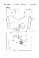
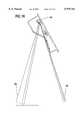
- FIG. 1shows a scanning system for reading coded indicia made in accordance with the teachings of the present invention
- FIG. 2is a layout diagram of the preferred embodiment of the scanning system made in accordance with the teachings of the present invention
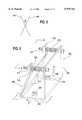
- FIG. 3shows, in perspective, a first embodiment of the scanning system for reading coded indicia made in accordance with the teachings of the present invention
- FIG. 4is a schematic layout of the reflected light beams
- FIG. 5is a schematic of the scanning pattern of the first embodiment
- FIG. 6is a perspective view of the adjustable mirror made in accordance with the teachings of the present invention.
- FIG. 7is a view along line 7--7 of FIG. 6;
- FIG. 8is a view along line 8--8 of FIG. 6;
- FIG. 9is a view along line 9--9 of FIG. 6;
- FIG. 10is an isometric view of an alternative embodiment of the adjustable mirror made in accordance with the teachings of the present invention.
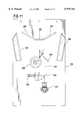
- FIG. 11is a layout diagram of a second embodiment of the scanning system made in accordance with the teachings of the present invention.
- FIG. 12is a schematic of the scanning pattern of the second embodiment
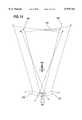
- FIG. 13is a simplified layout of a scanning mechanism of a third embodiment made in accordance with the teachings of the present invention.
- FIG. 14is a schematic layout of the reflected light beams
- FIG. 15is a schematic of how adjustment of the adjustable mirror changes the X scanning pattern.
- FIG. 16shows a 5° and a 20° variation in the X scanning pattern.
- FIG. 1A scanning system 1 made in accordance with the teachings of the present invention is shown in FIG. 1.
- the scanning system 1is particularly adapted for scanning coded symbologies, preferably bar code symbols, placed on articles 12 traveling on a conveyor belt 14 moving in the direction of arrow 15.
- the scanning device 1is enclosed in a rigid housing 16 having a transparent read window 17.
- the scanning system 1provides an adjustable X pattern 25 through the read window 17 for the detection of a bar code symbol.
- the scanning module 10includes a light source 20, an apertured mirror 39, a deflecting mirror 60, a rotating polygonal mirror 80, a plurality of adjustable mirrors 21, 22, 23 and 24 and a photodetector 29.
- the light source 20includes a lens assembly 30 and a laser diode 31 to produce a coherent light beam 40.
- the size and power of the laser diode 31depends upon the particular application.
- the light source 20produces the beam 40 which passes through an aperture in mirror 39 before being deflected by the deflecting mirror 60 onto the rotating polygonal mirror 80.
- the polygonal mirror 80is mounted on a shaft 81 connected to a controllable DC motor (not shown).
- the rotating mirror 80has a plurality of reflective facets.
- the beam 40 striking the rotating polygonal mirror 80produces a scan line 11 which sweeps in the direction of rotation of the polygonal mirror 80 to strike the series of adjustable mirrors 21, 22, 23 and 24.
- Each of the mirror assemblies 21, 22, 23 and 24is adapted to reflect the beam 11 at a different angle from the base reference plane depending on the assemblies' orientation. As shown in FIGS. 3 and 4, the adjustable mirrors 21, 22, 23 and 24 create an adjustable X pattern which is projected outward through the read window 17 of the scanning system 1.
- a beam collection apparatussuch as a photo detector 29, as shown in FIG. 2.
- the photo detector 29converts the received detected light into an electrical signal, which is then converted into a digital signal by an analog to digital converter, (not shown).
- This signalis forwarded to a decoding means, (not shown), such as a microprocessor, which processes the signal to determine the data representative of the light and dark portions of the scanned coded symbology.
- the microprocessoruses the information to reconstruct the bar code symbol using reconstruction and decoding techniques that are well known to those of skill in the art.
- the X patternis produced from the sweep created by the beam 11 striking the mirror assemblies 21, 22, 23 and 24. Proceeding from right to left in FIG. 4, the beam 11 is swept on the mirrors 22 and 23. Beam 11 initially strikes mirror 22 at point a. This beam of light then strikes mirror 21 at point a' and is reflected to provide the initial point a" of the first leg 104 of the X pattern. As the beam 11 is swept across mirror 22 from point a to point b, the reflected light creates leg 104 between points a" and b". First leg 104 of the X moves diagonally from top to bottom. Beam 11 then sweeps across mirror 23 from point c to point d.
- the X patterngenerally comprises legs 104 and 106 at an angle ⁇ relative to one another.
- the mirrors 21-24can be adjusted to vary the angle ⁇ .
- Adjustment of the X patternis desirable to account for variations in the scanning process including conveyor speed, height of the bar code symbols and relative placement of the bar code symbol on the package. For example, at a given conveyor speed, as the angle decreases, the minimum bar height of the bar code symbol also decreases, but at the expense of a smaller placement variation. As the angle increases, the placement variation also increases, but at the expense of a larger minimum bar code symbol height.
- the X patternis adjustable to optimize the required placement variation and minimize the required bar code symbol height.
- the X pattern of the present embodimentis adjustable in the range of approximately 20 to 90 degrees between the two legs of the X pattern. With the range of 20 to 90 degrees, the X pattern is ideal for scanning bar code symbols in a picket fence orientation with a greater range of tilt than standard vibrating vane scanners can accommodate. At 90 degrees, the pattern is a standard X pattern and is suitable for omni-directional scanning.
- Variation of the angle between the two legs of the X patternalso varies the displacement of the X pattern relative to the scanner module 10 as shown at positions 26, 27 and 28 in FIG. 3.
- the position of the scanner housing 16 relative to the conveyorcan be adjusted to compensate for this displacement or to finalize the angle of the X pattern on the bar code.
- the adjustable mirror assemblies 200are shown in greater detail in FIG. 6.
- the mirror assemblies 200include a backing piece 202, a base plate 204 and a reflective mirror face 206.
- the reflective mirror face 206is hingedly attached by a flexible piece 212 to the base plate 204.
- the reflective mirror piece 206is further connected to the backing piece 202 by threaded bolts 210.
- the bolts 210are positioned through tabs 216 which extend from the reflective portion 206. Subsequent tightening and untightening of the bolts 210 allows for tilting of the mirror piece 206 relative to the plane of the backing piece 202.
- the mirror assembly 200is mounted on the scanning mechanism by bolts 208 and 209 through holes in the base plate 204.
- One of the bolts 208is positioned for movement within a slot 214 cut into the base plate 204. Movement of the bolt 208 within the slot 214 permits pivotal adjustment of the mirror assembly 200. Adjustment is accomplished by loosening the bolt 208 and moving the mirror assembly 200 back or forth to the desired position in the slot 214. If desired, a second slot 214 may be provided such that the entire assembly 200 may be moved fore and aft. Accordingly, the reflective portion 206 can be tilted forward and backward by adjustment of the bolts 210 and pivoted by adjustment of the bolt 208 to change the orientation of the X pattern.
- various components of the mirror assembly 200are motorized to allow the mirror assembly 200 to be selectively adjusted automatically, depending upon the scanning application.
- An example of such an embodimentis shown in FIG. 10.
- An electric motor 500is attached to each bolt 210 to provide automated adjustment of the angle of the reflective surface 206.
- a linear actuator 502is provided to adjust the rotational orientation of the mirror assembly 200.
- the bolt 208may be replaced by a pin 504. It will be understood by those skilled in the art that a number of different controls may be used to adjust the mirror assemblies 200.
- the scanning system 250includes a light source 251, an appertured mirror 252, a deflecting mirror 254, a rotating polygonal mirror 258, a plurality of adjustable mirrors 261, 262, 263, 264 and 265 and a photo detector 259.
- the light source 251, such as a laser diodeproduces a coherent beam of light 253 which is deflected by the deflecting mirror 254 to the rotating polygonal mirror 258.
- the rotating mirror 258rotates to sweep the scan line 256 across the adjustable mirrors 261, 262, 263, 264 and 265.
- the adjustable mirrors 261, 262, 263, 264 and 265create an X pattern which is adjustable in the range of approximately 20 to 90 degrees between the legs of the X.
- the X pattern in the present embodimentconsists of two angled lines 268, 269 which intersect to form the shape of an "X" and a single straight line 270 running horizontally through the intersection of the two lines 268, 269. It should be recognized by those of skill in the art that X patterns can be created with a vertical bar or a horizontal bar. The X pattern which best fits a particular application is utilized. The addition of the third line 270 makes the scanning pattern omni-directional when used in conjunction with an angle ⁇ of 60 degrees or greater. When ⁇ is less than 60 degrees, the X pattern permits scanning of bar codes symbols in either a picket fence type orientation or a ladder orientation with a greater range of tilt than conventional scanners can accommodate.
- the scanning system 300includes a light source 330, an appertured mirror 304, a rotating polygonal mirror 316, a plurality of adjustable mirrors 321, 322 and 323 and a photo detector 326.
- the light source 330such as a laser diode, provides a coherent beam of light 302 through an aperture in mirror 304.
- the rotation of the polygonal mirror 316sweeps the beam 302 across the adjustable mirror assemblies 321, 322 and 323 as represented by lines 306.
- the adjustable mirror assemblies 321, 322 and 323are oriented such that an X pattern is produced.
- Each of the mirror assemblies 321, 322 and 323is adapted to reflect the beam 306 at a different angle from the base reference plane depending on the assemblies' orientation. Adjustment of the mirror assemblies 321, 322, and 323 allows the angle between the legs of the X pattern to be adjusted between approximately 5 and 20 degrees.
- the X patternis produced from the sweep created by the beam 306 striking the mirror assemblies 321, 322 and 323.
- the beam 306sweeps across the mirror 321, from a to b, it produces the first leg 344 of the X which moves diagonally from top a' to bottom b'.
- the beamsweeps across mirror 322 from c to d to produce a straight vertical center line 342 from c' to d' which intersects the first leg 344.
- the beam 306sweeps across mirror 323 from e to f to produce second leg 346 of the X which moves diagonally from bottom e' to top f' and intersects first leg 344.
- adjustment of mirrors 321 and 323 to the positions shown as 321' and 323'results in a modified X pattern.
- the adjusted mirrors 321' and 323'produce an X pattern with a larger angle ⁇ ' between the two legs 344', 346' then the angle ⁇ produced by the mirrors 321, 323 in their original positions.
- the angle ⁇ between the two legs 344, 346 of the X pattern of the present embodiment patterncan be adjusted between approximately 5 and 20 degrees.
- a scanner with such an adjustable angle ⁇permits scanning of bar codes with minimal bar heights in ladder or picket fence orientation with a greater range of tilt than conventional scanners. This scanner is particularly suitable for two-dimensional bar code symbologies such as PDF-417.
- the center line 342is removed from the X pattern by removing the center mirror assembly 322.
- the mirrors 321 and 323can be correspondingly lengthened.
- adjustment of the legs 344, 346 of the X patternalso changes the displacement of the X pattern.
- an X pattern with an angle ⁇ of 5° between the two legs 344, 346, as shown at 402and an X pattern with an angle ⁇ of 20° between the two legs 344, 346, as shown at 404, have varying displacements with respect to the scanner housing 400.
- the scanner housing 400may be correspondingly adjusted to keep the X scan pattern focused at a specific location.
- Advantages of utilizing an adjustable X patterninclude the ability to handle any tilt angle between the legs of the X pattern. As the bar code symbol moves thru the X pattern, the partial scans collected by the adjustable X pattern are combined and decoded by the data reconstruction software. Another advantage of the present invention is the elimination of moving parts, such as a vibrating vane type scanning attachment, which are expensive and prone to failure.
Landscapes
- Physics & Mathematics (AREA)
- Electromagnetism (AREA)
- Engineering & Computer Science (AREA)
- Health & Medical Sciences (AREA)
- General Health & Medical Sciences (AREA)
- Toxicology (AREA)
- Artificial Intelligence (AREA)
- Computer Vision & Pattern Recognition (AREA)
- General Physics & Mathematics (AREA)
- Theoretical Computer Science (AREA)
- Mechanical Optical Scanning Systems (AREA)
Abstract
Description
Claims (28)
Priority Applications (1)
| Application Number | Priority Date | Filing Date | Title |
|---|---|---|---|
| US08/970,726US5979761A (en) | 1996-11-18 | 1997-11-14 | Bar code laser scanner having a plurality of adjustable mirrors |
Applications Claiming Priority (2)
| Application Number | Priority Date | Filing Date | Title |
|---|---|---|---|
| US3130796P | 1996-11-18 | 1996-11-18 | |
| US08/970,726US5979761A (en) | 1996-11-18 | 1997-11-14 | Bar code laser scanner having a plurality of adjustable mirrors |
Publications (1)
| Publication Number | Publication Date |
|---|---|
| US5979761Atrue US5979761A (en) | 1999-11-09 |
Family
ID=26707064
Family Applications (1)
| Application Number | Title | Priority Date | Filing Date |
|---|---|---|---|
| US08/970,726Expired - LifetimeUS5979761A (en) | 1996-11-18 | 1997-11-14 | Bar code laser scanner having a plurality of adjustable mirrors |
Country Status (1)
| Country | Link |
|---|---|
| US (1) | US5979761A (en) |
Cited By (16)
| Publication number | Priority date | Publication date | Assignee | Title |
|---|---|---|---|---|
| US6237051B1 (en)* | 1997-07-24 | 2001-05-22 | Data Capture Institute | Asset tracking within and across enterprise boundaries |
| US6325289B1 (en)* | 1997-12-24 | 2001-12-04 | Datalogic S.P.A. | Apparatus and process for focusing a laser beam for reading optical codes |
| US6588668B1 (en)* | 1999-10-26 | 2003-07-08 | Tohoku Ricoh Co., Ltd. | Bar code scanner |
| US20040026511A1 (en)* | 2002-08-07 | 2004-02-12 | Shenzhen Syscan Technology Co., Limited. | Guiding a scanning device to decode 2D symbols |
| US20040035931A1 (en)* | 2001-06-08 | 2004-02-26 | Tamiaki Matsuura | Integrated optical apparatus |
| US20040084532A1 (en)* | 2002-05-02 | 2004-05-06 | Leuze Electronic Gmbh & Co. | Optical sensor |
| US20050077358A1 (en)* | 2003-10-08 | 2005-04-14 | Thomas Boehm | System and method for configuring an omnidirectional scanner |
| US7048192B2 (en)* | 1998-12-03 | 2006-05-23 | Metrologic Instruments, Inc. | Wireless bar code symbol reading system employing a base station with a cradle having a hinged support hooks for enabling vertical and horizontal installations |
| US20070019528A1 (en)* | 2005-07-22 | 2007-01-25 | Primax Electronics Ltd. | Optical reading head of scanning apparatus |
| US20080073435A1 (en)* | 2006-09-27 | 2008-03-27 | Shenzhen Mindray Bio-Medical Electronics Co., Ltd. | Code scanning device and code scanning method using the same |
| US20080099564A1 (en)* | 2006-10-26 | 2008-05-01 | Shenzhen Mindray Bio-Medical Electronics Co., Ltd. | Sample plate for supporting bar code scanning |
| US20090219599A1 (en)* | 2006-05-08 | 2009-09-03 | Optoelectronics Co., Ltd. | Changeable apparatus for single or raster scanning using polygon mirror |
| US20150122890A1 (en)* | 2013-11-04 | 2015-05-07 | Datalogic ADC, Inc. | Data reading system and method for multi-view imaging using an adjustable mirror |
| US10812727B1 (en) | 2019-12-16 | 2020-10-20 | Cognex Corporation | Machine vision system and method with steerable mirror |
| US11647290B2 (en) | 2019-12-16 | 2023-05-09 | Cognex Corporation | Machine vision system and method with steerable mirror |
| US11790656B2 (en) | 2019-12-16 | 2023-10-17 | Cognex Corporation | Machine vision system and method with steerable mirror |
Citations (17)
| Publication number | Priority date | Publication date | Assignee | Title |
|---|---|---|---|---|
| US3947816A (en)* | 1974-07-01 | 1976-03-30 | International Business Machines Corporation | Omnidirectional optical scanning apparatus |
| US4006343A (en)* | 1973-10-23 | 1977-02-01 | Matsushita Electric Industrial Co., Ltd. | Code read-out means |
| US4043632A (en)* | 1975-05-27 | 1977-08-23 | Data General Corporation | Scanning polygon with adjustable mirrors |
| US4093865A (en)* | 1977-04-29 | 1978-06-06 | National Semiconductor Corporation | Code symbol scanner using a double X bar pattern |
| US4795224A (en)* | 1986-10-06 | 1989-01-03 | Katsuchika Goto | Optical scanning pattern generator |
| US4871904A (en)* | 1987-12-28 | 1989-10-03 | Symbol Technologies, Inc. | Multidirectional optical scanner |
| US5000529A (en)* | 1989-04-20 | 1991-03-19 | Fujitsu Limited | Optical scanner |
| US5012079A (en)* | 1989-11-13 | 1991-04-30 | Lazerdata Corporation | Bar code scanner mirror assembly |
| US5132524A (en)* | 1990-05-21 | 1992-07-21 | Lazerdata Corporation | Multi directional laser scanner |
| US5229591A (en)* | 1988-10-21 | 1993-07-20 | Symbol Technologies, Inc. | Scanning system with adjustable light output and/or scanning angle |
| US5286961A (en)* | 1990-05-23 | 1994-02-15 | Tokyo Electric Co., Ltd. | Bar code reader producing two groups of vertical scan lines and two groups of inclined scan lines on a plane normal to the read window |
| US5296691A (en)* | 1992-09-14 | 1994-03-22 | Lazerdata Corporation | Scanning device for reconstructing a complete code from scanned segments |
| US5321246A (en)* | 1982-01-25 | 1994-06-14 | Symbol Technologies, Inc. | Bar code scanner with RF coupling to base terminal and automatic turn-off upon decode |
| US5464972A (en)* | 1992-07-01 | 1995-11-07 | Reflexion Plus | Omnidirectional bar code label scanner |
| US5478998A (en)* | 1993-05-10 | 1995-12-26 | Symbol Technologies, Inc. | Tilting wall-mounted optical scanner |
| US5481097A (en)* | 1993-01-25 | 1996-01-02 | Psc Inc. | Apparatus and method for decoding bar codes |
| US5600120A (en)* | 1993-09-21 | 1997-02-04 | Opticon Sensors Europe B.V. | Helical scanning pattern generator |
- 1997
- 1997-11-14USUS08/970,726patent/US5979761A/ennot_activeExpired - Lifetime
Patent Citations (17)
| Publication number | Priority date | Publication date | Assignee | Title |
|---|---|---|---|---|
| US4006343A (en)* | 1973-10-23 | 1977-02-01 | Matsushita Electric Industrial Co., Ltd. | Code read-out means |
| US3947816A (en)* | 1974-07-01 | 1976-03-30 | International Business Machines Corporation | Omnidirectional optical scanning apparatus |
| US4043632A (en)* | 1975-05-27 | 1977-08-23 | Data General Corporation | Scanning polygon with adjustable mirrors |
| US4093865A (en)* | 1977-04-29 | 1978-06-06 | National Semiconductor Corporation | Code symbol scanner using a double X bar pattern |
| US5321246A (en)* | 1982-01-25 | 1994-06-14 | Symbol Technologies, Inc. | Bar code scanner with RF coupling to base terminal and automatic turn-off upon decode |
| US4795224A (en)* | 1986-10-06 | 1989-01-03 | Katsuchika Goto | Optical scanning pattern generator |
| US4871904A (en)* | 1987-12-28 | 1989-10-03 | Symbol Technologies, Inc. | Multidirectional optical scanner |
| US5229591A (en)* | 1988-10-21 | 1993-07-20 | Symbol Technologies, Inc. | Scanning system with adjustable light output and/or scanning angle |
| US5000529A (en)* | 1989-04-20 | 1991-03-19 | Fujitsu Limited | Optical scanner |
| US5012079A (en)* | 1989-11-13 | 1991-04-30 | Lazerdata Corporation | Bar code scanner mirror assembly |
| US5132524A (en)* | 1990-05-21 | 1992-07-21 | Lazerdata Corporation | Multi directional laser scanner |
| US5286961A (en)* | 1990-05-23 | 1994-02-15 | Tokyo Electric Co., Ltd. | Bar code reader producing two groups of vertical scan lines and two groups of inclined scan lines on a plane normal to the read window |
| US5464972A (en)* | 1992-07-01 | 1995-11-07 | Reflexion Plus | Omnidirectional bar code label scanner |
| US5296691A (en)* | 1992-09-14 | 1994-03-22 | Lazerdata Corporation | Scanning device for reconstructing a complete code from scanned segments |
| US5481097A (en)* | 1993-01-25 | 1996-01-02 | Psc Inc. | Apparatus and method for decoding bar codes |
| US5478998A (en)* | 1993-05-10 | 1995-12-26 | Symbol Technologies, Inc. | Tilting wall-mounted optical scanner |
| US5600120A (en)* | 1993-09-21 | 1997-02-04 | Opticon Sensors Europe B.V. | Helical scanning pattern generator |
Cited By (24)
| Publication number | Priority date | Publication date | Assignee | Title |
|---|---|---|---|---|
| US6237051B1 (en)* | 1997-07-24 | 2001-05-22 | Data Capture Institute | Asset tracking within and across enterprise boundaries |
| US6325289B1 (en)* | 1997-12-24 | 2001-12-04 | Datalogic S.P.A. | Apparatus and process for focusing a laser beam for reading optical codes |
| US7048192B2 (en)* | 1998-12-03 | 2006-05-23 | Metrologic Instruments, Inc. | Wireless bar code symbol reading system employing a base station with a cradle having a hinged support hooks for enabling vertical and horizontal installations |
| US6588668B1 (en)* | 1999-10-26 | 2003-07-08 | Tohoku Ricoh Co., Ltd. | Bar code scanner |
| US20040035931A1 (en)* | 2001-06-08 | 2004-02-26 | Tamiaki Matsuura | Integrated optical apparatus |
| US6905069B2 (en)* | 2002-05-02 | 2005-06-14 | Leuze Electronic Gmbh & Co. | Optical sensor |
| US20040084532A1 (en)* | 2002-05-02 | 2004-05-06 | Leuze Electronic Gmbh & Co. | Optical sensor |
| US20040026511A1 (en)* | 2002-08-07 | 2004-02-12 | Shenzhen Syscan Technology Co., Limited. | Guiding a scanning device to decode 2D symbols |
| US6802450B2 (en)* | 2002-08-07 | 2004-10-12 | Shenzhen Syscan Technology Co. Ltd | Guiding a scanning device to decode 2D symbols |
| US20050077358A1 (en)* | 2003-10-08 | 2005-04-14 | Thomas Boehm | System and method for configuring an omnidirectional scanner |
| US20070019528A1 (en)* | 2005-07-22 | 2007-01-25 | Primax Electronics Ltd. | Optical reading head of scanning apparatus |
| US7556196B2 (en)* | 2005-07-22 | 2009-07-07 | Teng Kuang Lee | Optical reading head of scanning apparatus |
| US20090219599A1 (en)* | 2006-05-08 | 2009-09-03 | Optoelectronics Co., Ltd. | Changeable apparatus for single or raster scanning using polygon mirror |
| US20080073435A1 (en)* | 2006-09-27 | 2008-03-27 | Shenzhen Mindray Bio-Medical Electronics Co., Ltd. | Code scanning device and code scanning method using the same |
| US9152836B2 (en) | 2006-09-27 | 2015-10-06 | Shenzhen Mindray Bio-Medical Electronics Co., Ltd. | Code scanning device and code scanning method using the same |
| US20080099564A1 (en)* | 2006-10-26 | 2008-05-01 | Shenzhen Mindray Bio-Medical Electronics Co., Ltd. | Sample plate for supporting bar code scanning |
| US7931201B2 (en) | 2006-10-26 | 2011-04-26 | Shenzhen Mindray Bio-Medical Electronics Co., Ltd. | Sample plate for supporting bar code scanning |
| US20150122890A1 (en)* | 2013-11-04 | 2015-05-07 | Datalogic ADC, Inc. | Data reading system and method for multi-view imaging using an adjustable mirror |
| US10002271B2 (en)* | 2013-11-04 | 2018-06-19 | Datalogic Usa, Inc. | Data reading system and method for multi-view imaging using an adjustable mirror |
| US10812727B1 (en) | 2019-12-16 | 2020-10-20 | Cognex Corporation | Machine vision system and method with steerable mirror |
| US11240436B2 (en) | 2019-12-16 | 2022-02-01 | Cognex Corporation | Machine vision system and method with steerable mirror |
| US11647290B2 (en) | 2019-12-16 | 2023-05-09 | Cognex Corporation | Machine vision system and method with steerable mirror |
| US11790656B2 (en) | 2019-12-16 | 2023-10-17 | Cognex Corporation | Machine vision system and method with steerable mirror |
| US11803049B2 (en) | 2019-12-16 | 2023-10-31 | Cognex Corporation | Machine vision system and method with steerable mirror |
Similar Documents
| Publication | Publication Date | Title |
|---|---|---|
| US5979761A (en) | Bar code laser scanner having a plurality of adjustable mirrors | |
| KR940002961B1 (en) | Multidirectional Barcode Reader | |
| US6536668B1 (en) | Dual aperture optical scanner | |
| US3928759A (en) | Omnidirectional scanner for reading digitally encoded tickets | |
| US6460767B1 (en) | Optical scanner for omni-directional scanning of code symbols within a scanning volume | |
| EP0348232B1 (en) | Optical beam scanner for reading bar-codes | |
| EP0778538B1 (en) | Optical scanner | |
| EP0460684B1 (en) | Optical information reading apparatus | |
| EP0260155A2 (en) | Shallow bar code scanner | |
| JPH0424776A (en) | Nondirectional laser scanner | |
| US6840453B2 (en) | Optical scanning apparatus | |
| EP0532205A2 (en) | Method of producing an omnidirectional scan pattern | |
| US5179271A (en) | Compact optical scan pattern generator for bar code reading systems | |
| US7055745B2 (en) | Laser scanning method and system employing visible scanning-zone indicators identifying a three-dimensional omni-directional laser scanning volume for package transport | |
| EP1783661A1 (en) | Optical scanner | |
| EP0848344B2 (en) | A scanning reader of an optical code placed on an article in movement and a method of scanning said optical code by means of said reader | |
| JPH0823629B2 (en) | Optical reader | |
| US5223700A (en) | Bar code reader having a polygon mirror providing different scan line lengths | |
| CA2031824C (en) | Symbol reader | |
| EP1526475A2 (en) | Optical scanner having enhanced item side coverage | |
| JPH05205088A (en) | Device and method of changing focus of optical scanner | |
| EP0533383A2 (en) | Optical scanner apparatus | |
| US5610385A (en) | Optical bar code scanner which produces substantially perpendicular scan lines | |
| CA2020540C (en) | Bar code reader | |
| JP2602173Y2 (en) | Code reader |
Legal Events
| Date | Code | Title | Description |
|---|---|---|---|
| AS | Assignment | Owner name:ACCU-SORT SYSTEMS, INC., A CORP. OF PENNSYLVANIA, Free format text:ASSIGNMENT OF ASSIGNORS INTEREST;ASSIGNORS:WURZ, DAVID A.;VEKSLAND, MICHAEL;REEL/FRAME:009122/0283 Effective date:19980406 | |
| STCF | Information on status: patent grant | Free format text:PATENTED CASE | |
| CC | Certificate of correction | ||
| AS | Assignment | Owner name:UNION NATIONAL BANK AND TRUST COMPANY OF SOUDERTON Free format text:SECURITY INTEREST;ASSIGNOR:ACCU-SORT SYSTEMS, INC.;REEL/FRAME:013333/0727 Effective date:20020627 | |
| FPAY | Fee payment | Year of fee payment:4 | |
| FEPP | Fee payment procedure | Free format text:PAT HOLDER NO LONGER CLAIMS SMALL ENTITY STATUS, ENTITY STATUS SET TO UNDISCOUNTED (ORIGINAL EVENT CODE: STOL); ENTITY STATUS OF PATENT OWNER: LARGE ENTITY | |
| REFU | Refund | Free format text:REFUND - PAYMENT OF MAINTENANCE FEE, 8TH YR, SMALL ENTITY (ORIGINAL EVENT CODE: R2552); ENTITY STATUS OF PATENT OWNER: LARGE ENTITY | |
| FPAY | Fee payment | Year of fee payment:8 | |
| FPAY | Fee payment | Year of fee payment:12 | |
| AS | Assignment | Owner name:ACCU-SORT SYSTEMS, INC., PENNSYLVANIA Free format text:RELEASE BY SECURED PARTY;ASSIGNOR:UNIVEST NATIONAL BANK AND TRUST COMPANY (FKA UNION NATIONAL BANK AND TRUST COMPANY OF SOUDERTON);REEL/FRAME:027206/0742 Effective date:20111005 | |
| AS | Assignment | Owner name:DATALOGIC AUTOMATION, INC., PENNSYLVANIA Free format text:MERGER AND CHANGE OF NAME;ASSIGNORS:DATALOGIC AUTOMATION, INC.;ACCU-SORT SYSTEMS, INC.;REEL/FRAME:036327/0443 Effective date:20120701 |