US5979494A - Pneumatic controls for ophthalmic surgical system - Google Patents
Pneumatic controls for ophthalmic surgical systemDownload PDFInfo
- Publication number
- US5979494A US5979494AUS09/201,318US20131898AUS5979494AUS 5979494 AUS5979494 AUS 5979494AUS 20131898 AUS20131898 AUS 20131898AUS 5979494 AUS5979494 AUS 5979494A
- Authority
- US
- United States
- Prior art keywords
- valve
- pressure
- control
- pneumatic
- console
- Prior art date
- Legal status (The legal status is an assumption and is not a legal conclusion. Google has not performed a legal analysis and makes no representation as to the accuracy of the status listed.)
- Expired - Fee Related
Links
Images


Classifications
- A—HUMAN NECESSITIES
- A61—MEDICAL OR VETERINARY SCIENCE; HYGIENE
- A61M—DEVICES FOR INTRODUCING MEDIA INTO, OR ONTO, THE BODY; DEVICES FOR TRANSDUCING BODY MEDIA OR FOR TAKING MEDIA FROM THE BODY; DEVICES FOR PRODUCING OR ENDING SLEEP OR STUPOR
- A61M1/00—Suction or pumping devices for medical purposes; Devices for carrying-off, for treatment of, or for carrying-over, body-liquids; Drainage systems
- A61M1/71—Suction drainage systems
- A61M1/74—Suction control
- A—HUMAN NECESSITIES
- A61—MEDICAL OR VETERINARY SCIENCE; HYGIENE
- A61M—DEVICES FOR INTRODUCING MEDIA INTO, OR ONTO, THE BODY; DEVICES FOR TRANSDUCING BODY MEDIA OR FOR TAKING MEDIA FROM THE BODY; DEVICES FOR PRODUCING OR ENDING SLEEP OR STUPOR
- A61M1/00—Suction or pumping devices for medical purposes; Devices for carrying-off, for treatment of, or for carrying-over, body-liquids; Drainage systems
- A61M1/71—Suction drainage systems
- A61M1/72—Cassettes forming partially or totally the fluid circuit
- A—HUMAN NECESSITIES
- A61—MEDICAL OR VETERINARY SCIENCE; HYGIENE
- A61B—DIAGNOSIS; SURGERY; IDENTIFICATION
- A61B18/00—Surgical instruments, devices or methods for transferring non-mechanical forms of energy to or from the body
- A61B18/04—Surgical instruments, devices or methods for transferring non-mechanical forms of energy to or from the body by heating
- A61B18/12—Surgical instruments, devices or methods for transferring non-mechanical forms of energy to or from the body by heating by passing a current through the tissue to be heated, e.g. high-frequency current
- A61B18/14—Probes or electrodes therefor
- A61B18/1402—Probes for open surgery
- A—HUMAN NECESSITIES
- A61—MEDICAL OR VETERINARY SCIENCE; HYGIENE
- A61B—DIAGNOSIS; SURGERY; IDENTIFICATION
- A61B17/00—Surgical instruments, devices or methods
- A61B2017/00535—Surgical instruments, devices or methods pneumatically or hydraulically operated
- A61B2017/00544—Surgical instruments, devices or methods pneumatically or hydraulically operated pneumatically
- A—HUMAN NECESSITIES
- A61—MEDICAL OR VETERINARY SCIENCE; HYGIENE
- A61B—DIAGNOSIS; SURGERY; IDENTIFICATION
- A61B17/00—Surgical instruments, devices or methods
- A61B2017/00973—Surgical instruments, devices or methods pedal-operated
- A—HUMAN NECESSITIES
- A61—MEDICAL OR VETERINARY SCIENCE; HYGIENE
- A61B—DIAGNOSIS; SURGERY; IDENTIFICATION
- A61B90/00—Instruments, implements or accessories specially adapted for surgery or diagnosis and not covered by any of the groups A61B1/00 - A61B50/00, e.g. for luxation treatment or for protecting wound edges
- A61B90/30—Devices for illuminating a surgical field, the devices having an interrelation with other surgical devices or with a surgical procedure
- A61B2090/306—Devices for illuminating a surgical field, the devices having an interrelation with other surgical devices or with a surgical procedure using optical fibres
- A—HUMAN NECESSITIES
- A61—MEDICAL OR VETERINARY SCIENCE; HYGIENE
- A61F—FILTERS IMPLANTABLE INTO BLOOD VESSELS; PROSTHESES; DEVICES PROVIDING PATENCY TO, OR PREVENTING COLLAPSING OF, TUBULAR STRUCTURES OF THE BODY, e.g. STENTS; ORTHOPAEDIC, NURSING OR CONTRACEPTIVE DEVICES; FOMENTATION; TREATMENT OR PROTECTION OF EYES OR EARS; BANDAGES, DRESSINGS OR ABSORBENT PADS; FIRST-AID KITS
- A61F9/00—Methods or devices for treatment of the eyes; Devices for putting in contact-lenses; Devices to correct squinting; Apparatus to guide the blind; Protective devices for the eyes, carried on the body or in the hand
- A61F9/007—Methods or devices for eye surgery
- A61F9/00736—Instruments for removal of intra-ocular material or intra-ocular injection, e.g. cataract instruments
- A61F9/00745—Instruments for removal of intra-ocular material or intra-ocular injection, e.g. cataract instruments using mechanical vibrations, e.g. ultrasonic
- A—HUMAN NECESSITIES
- A61—MEDICAL OR VETERINARY SCIENCE; HYGIENE
- A61F—FILTERS IMPLANTABLE INTO BLOOD VESSELS; PROSTHESES; DEVICES PROVIDING PATENCY TO, OR PREVENTING COLLAPSING OF, TUBULAR STRUCTURES OF THE BODY, e.g. STENTS; ORTHOPAEDIC, NURSING OR CONTRACEPTIVE DEVICES; FOMENTATION; TREATMENT OR PROTECTION OF EYES OR EARS; BANDAGES, DRESSINGS OR ABSORBENT PADS; FIRST-AID KITS
- A61F9/00—Methods or devices for treatment of the eyes; Devices for putting in contact-lenses; Devices to correct squinting; Apparatus to guide the blind; Protective devices for the eyes, carried on the body or in the hand
- A61F9/007—Methods or devices for eye surgery
- A61F9/013—Instruments for compensation of ocular refraction ; Instruments for use in cornea removal, for reshaping or performing incisions in the cornea
- A—HUMAN NECESSITIES
- A61—MEDICAL OR VETERINARY SCIENCE; HYGIENE
- A61M—DEVICES FOR INTRODUCING MEDIA INTO, OR ONTO, THE BODY; DEVICES FOR TRANSDUCING BODY MEDIA OR FOR TAKING MEDIA FROM THE BODY; DEVICES FOR PRODUCING OR ENDING SLEEP OR STUPOR
- A61M1/00—Suction or pumping devices for medical purposes; Devices for carrying-off, for treatment of, or for carrying-over, body-liquids; Drainage systems
- A61M1/71—Suction drainage systems
- A61M1/77—Suction-irrigation systems
- A—HUMAN NECESSITIES
- A61—MEDICAL OR VETERINARY SCIENCE; HYGIENE
- A61M—DEVICES FOR INTRODUCING MEDIA INTO, OR ONTO, THE BODY; DEVICES FOR TRANSDUCING BODY MEDIA OR FOR TAKING MEDIA FROM THE BODY; DEVICES FOR PRODUCING OR ENDING SLEEP OR STUPOR
- A61M1/00—Suction or pumping devices for medical purposes; Devices for carrying-off, for treatment of, or for carrying-over, body-liquids; Drainage systems
- A61M1/80—Suction pumps
- A61M1/804—Suction pumps using Laval or Venturi jet pumps
- A—HUMAN NECESSITIES
- A61—MEDICAL OR VETERINARY SCIENCE; HYGIENE
- A61M—DEVICES FOR INTRODUCING MEDIA INTO, OR ONTO, THE BODY; DEVICES FOR TRANSDUCING BODY MEDIA OR FOR TAKING MEDIA FROM THE BODY; DEVICES FOR PRODUCING OR ENDING SLEEP OR STUPOR
- A61M2205/00—General characteristics of the apparatus
- A61M2205/12—General characteristics of the apparatus with interchangeable cassettes forming partially or totally the fluid circuit
- Y—GENERAL TAGGING OF NEW TECHNOLOGICAL DEVELOPMENTS; GENERAL TAGGING OF CROSS-SECTIONAL TECHNOLOGIES SPANNING OVER SEVERAL SECTIONS OF THE IPC; TECHNICAL SUBJECTS COVERED BY FORMER USPC CROSS-REFERENCE ART COLLECTIONS [XRACs] AND DIGESTS
- Y10—TECHNICAL SUBJECTS COVERED BY FORMER USPC
- Y10T—TECHNICAL SUBJECTS COVERED BY FORMER US CLASSIFICATION
- Y10T137/00—Fluid handling
- Y10T137/2496—Self-proportioning or correlating systems
- Y10T137/2544—Supply and exhaust type
- Y—GENERAL TAGGING OF NEW TECHNOLOGICAL DEVELOPMENTS; GENERAL TAGGING OF CROSS-SECTIONAL TECHNOLOGIES SPANNING OVER SEVERAL SECTIONS OF THE IPC; TECHNICAL SUBJECTS COVERED BY FORMER USPC CROSS-REFERENCE ART COLLECTIONS [XRACs] AND DIGESTS
- Y10—TECHNICAL SUBJECTS COVERED BY FORMER USPC
- Y10T—TECHNICAL SUBJECTS COVERED BY FORMER US CLASSIFICATION
- Y10T137/00—Fluid handling
- Y10T137/7722—Line condition change responsive valves
- Y10T137/7758—Pilot or servo controlled
- Y10T137/7761—Electrically actuated valve
- Y—GENERAL TAGGING OF NEW TECHNOLOGICAL DEVELOPMENTS; GENERAL TAGGING OF CROSS-SECTIONAL TECHNOLOGIES SPANNING OVER SEVERAL SECTIONS OF THE IPC; TECHNICAL SUBJECTS COVERED BY FORMER USPC CROSS-REFERENCE ART COLLECTIONS [XRACs] AND DIGESTS
- Y10—TECHNICAL SUBJECTS COVERED BY FORMER USPC
- Y10T—TECHNICAL SUBJECTS COVERED BY FORMER US CLASSIFICATION
- Y10T137/00—Fluid handling
- Y10T137/8376—Combined
- Y—GENERAL TAGGING OF NEW TECHNOLOGICAL DEVELOPMENTS; GENERAL TAGGING OF CROSS-SECTIONAL TECHNOLOGIES SPANNING OVER SEVERAL SECTIONS OF THE IPC; TECHNICAL SUBJECTS COVERED BY FORMER USPC CROSS-REFERENCE ART COLLECTIONS [XRACs] AND DIGESTS
- Y10—TECHNICAL SUBJECTS COVERED BY FORMER USPC
- Y10T—TECHNICAL SUBJECTS COVERED BY FORMER US CLASSIFICATION
- Y10T137/00—Fluid handling
- Y10T137/8593—Systems
- Y10T137/877—With flow control means for branched passages
- Y10T137/87708—With common valve operator
- Y10T137/87772—With electrical actuation
- Y—GENERAL TAGGING OF NEW TECHNOLOGICAL DEVELOPMENTS; GENERAL TAGGING OF CROSS-SECTIONAL TECHNOLOGIES SPANNING OVER SEVERAL SECTIONS OF THE IPC; TECHNICAL SUBJECTS COVERED BY FORMER USPC CROSS-REFERENCE ART COLLECTIONS [XRACs] AND DIGESTS
- Y10—TECHNICAL SUBJECTS COVERED BY FORMER USPC
- Y10T—TECHNICAL SUBJECTS COVERED BY FORMER US CLASSIFICATION
- Y10T137/00—Fluid handling
- Y10T137/8593—Systems
- Y10T137/877—With flow control means for branched passages
- Y10T137/87877—Single inlet with multiple distinctly valved outlets
- Y—GENERAL TAGGING OF NEW TECHNOLOGICAL DEVELOPMENTS; GENERAL TAGGING OF CROSS-SECTIONAL TECHNOLOGIES SPANNING OVER SEVERAL SECTIONS OF THE IPC; TECHNICAL SUBJECTS COVERED BY FORMER USPC CROSS-REFERENCE ART COLLECTIONS [XRACs] AND DIGESTS
- Y10—TECHNICAL SUBJECTS COVERED BY FORMER USPC
- Y10T—TECHNICAL SUBJECTS COVERED BY FORMER US CLASSIFICATION
- Y10T137/00—Fluid handling
- Y10T137/8593—Systems
- Y10T137/877—With flow control means for branched passages
- Y10T137/87885—Sectional block structure
Definitions
- the present inventionrelates in general to pneumatic control circuits and systems for providing controlled levels of pressurized air or vacuum to instruments used during ophthalmic microsurgical procedures, and in particular to improvements in such pneumatic circuits and to a method of modularly constructing such pneumatic circuits within a drawer assembly.
- aspirationthat is providing suction via a controlled vacuum level
- Aspirationis used widely for various procedures and with various instruments.
- Aspirationis used, for example, during the engagement, stripping and removal of residual lens cortical material in extra-capsular cataract extraction and phacoemulsification procedures.
- Phaco-fragmentation proceduresalso make use of aspiration.
- Anterior and posterior vitrectomiesalso require aspiration for the removal of cut material from the eye, such as vitreous.
- Intraocular pressure (IOP) controlprovides precisely adjusted delivery of filtered air to the eye during posterior ocular pressure procedures. Also, the IOP system can be used to pressurize an irrigation supply of balanced salt solution for the eye during anterior segment procedures.
- Microscissorsare another ophthalmic microsurgical instrument which are often pneumatically driven. Three different scissor drive modes are known today: single cut mode, variable rate cut mode, and proportional cut mode.
- StorzStorz Instrument Co. of St. Louis, Mo.
- DAISYophthalmic microsurgical system
- the DAISY consolea pressure switch is used to monitor the incoming air pressure of the main supply line that provides air to the pneumatic system.
- the purpose of pressure switchis to detect abnormally low air pressure conditions which can exist, for example, if the hospital air supply pressure falls beneath expected levels or if some other problem interrupts the air supply to the DAISY console.
- this pressure switchis set to trip out at an appropriate level, such as 80 psig.
- IOP systemstypically operate in the range of 0 to 100 mmHg. At these pressure levels, it has not been possible previously, using on/off solenoid control valves, to ramp up air pressure to a desired setting in this range without overshoot. Further, in prior art IOP systems, there is a discernable variation in the output pressure of the IOP system from the desired pressure setting by as much as plus or minus four mmHg or more. Thus, is an object of the present invention to provide an IOP system which uses inexpensive on/off solenoid control valves, and yet still avoids overshoot and minimizes pressure variations from the desired IOP setting.
- the control systemis the type that has at least one pressure regulation means for limiting gas pressure downstream to a predetermined value, vacuum generation means, including at least one venturi for producing of vacuum from pressurized gas flow, and pressure sensing means for producing an electrical signal in response pressure at a predetermined location downstream from the regulation means and upstream from the vacuum generation means.
- the methodcomprises the steps of: (a) making the pressure sensing means a pressure transducer means for producing an analog signal accurately corresponding to actual pressure at the predetermined location; (b) monitoring the pressure at the predetermined location with the pressure transducer means to observe when pressure at the location falls beneath a minimum acceptable level; (c) monitoring the length of time that monitored pressure is continuously beneath the minimum acceptable value; and (d) instituting a safety procedure in the control console when the length of time that the monitored pressure is below the minimum acceptable value exceeds a predetermined length of time.
- an improved intraocular pressure (IOP) control systemof the type powered by a source of compressed gas.
- IOP control systemincludes the following components: at least one pressure regulation means for limiting gas pressure to a predetermined maximum value; first electromagnetically-actuated valve means for controlling flow of the compressed gas from its source to a location where such gas is put to use; and a second electromagnetically-actuated valve means for controlling flow of the compressed gas from the location to atmosphere to reduce pressure at such location.
- the improvement in this basic control systemcomprises: a third electromagnetically-actuated valve means for interrupting flow from the first valve means to the location; and variable volume gas reservoir means for accumulating additional compressed gas for later use, the reservoir means being located downstream of the first and third valve means.
- an improved electropneumatic control systemwhich provides a high-speed multi-cut mode in addition to a single cut mode and a proportional mode.
- the systemis of the type that is powered by a source of compressed gas such as air and includes at least one pressure regulator means for limiting gas pressure to a predetermined maximum value, and a first electromagnetically-actuated valve means for controlling flow of the compressed gas from the source to a location where the gas is put to use operating a microscissors or like gas-actuated microsurgical instrument.
- the improvementcomprises the combination of the foregoing two means and a second electromagnetically-actuated valve means, connected in parallel to and operating independently of the first valve means.
- the second valve meanscyclically controls the flow of compressed gas from the pressure regulator means to the location.
- the second valve meansmakes it possible to have a multi- cut mode for operating the microscissors or like instrument.
- the second valve meansis preferably a three-way, normally closed, two-position, solenoid-operated, spring-returned control valve.
- FIGS. 1A and 1Bare front and back perspective views of an ophthalmic microsurgical control console which utilizes the pneumatic control system of the present invention
- FIG. 2is a front view of the FIG. 1 control console showing the lay-out of the CRT visual display, control buttons or keys, surgical instrument connection ports and the like;
- FIG. 3is a plan view of the footswitch assembly usable with the present invention.
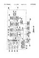
- FIG. 4Ais a simplified block diagram of the microprocessor-based electronic control system of the FIG. 1 control console showing how information is passed electronically between the microprocessor and the various boards and devices within the over-all surgical system;
- FIG. 4Bis a detailed block diagram of the operation of the CAC/bipolar board and equipment of the FIG. 1 control console;
- FIG. 4Cis a detailed block diagram of the calibration and drive system for a phaco probe
- FIG. 4Dis a detailed block diagram of the illumination lamp control circuitry and electrical hardware associated therewith;
- FIG. 4Eis a detailed block diagram of the pneumatics control and cassette control circuitry and related electrical equipment found in the pneumatic system and cassette system of the FIG. 1 console;
- FIG. 4Fis a detailed block diagram of the I/O expansion board shown in FIG. 4A and the electrical equipment interfaced therewith;
- FIG. 5is a detailed schematic diagram of the pneumatic control system which includes the improvements of the present invention.
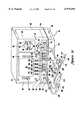
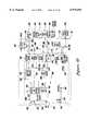
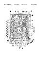
- FIG. 6is a plan view of a pneumatics drawer assembly of the present invention showing the preferred location of various components within the FIG. 5 pneumatic system;
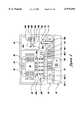
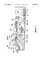
- FIG. 7is a longitudinal cross-sectional view of the FIG. 6 pneumatics drawer taken along line 7--7 in FIG. 5;
- FIG. 8is a cross-sectional view taken along line 8--8 of FIG. 5 showing an electrical connector board
- FIG. 9is a cross-sectional view taken along line 9--9 of FIG. 5 and showing the shelf and vibration dampening material supporting an electrically operated solenoid valve.
- FIGS. 1A, 1B and 2show a microsurgical control system 40 provided with an Illumination lamp drawer 41, an electronic control system housed in part in a nine-board electronic card rack 42, and a pneumatic control system 43 housed primarily in a pneumatic drawer module 44, and other modules which will be described later.
- the control system 40includes a system console 46 which has an upwardly and slightly inwardly-sloping front surface 47 with a primary front panel 48.
- On the front panel 48is an electronic display screen 50, a plurality of pushbuttons or touch sensitive pads 52 organized in two groups 54 and 56 along the left and right sides of the display screen 50, and a third group 58 along the bottom of the display screen 50.
- the console 46also includes a slot 70 for a conventional Storz aspirant collection cassette 72, a cassette eject button 74 and an irrigation pinch valve assembly 76.
- the electronic display screen 50is controlled by a microcomputer within the console 46 to provide several different menus or messages which instruct the operator as to the function of the pushbuttons 52 through 62.
- the operation of the display screen 50 in combination with the buttons 52-62may be best understood by looking at the enlarged view in FIG. 2.
- the display screen 50is shown there as being conceptually divided into central display screen region 82, left-side display region 84, right-side display region 86, bottom display region 88 and a top display region 90.
- the side regions 84 and 86each consist of six horizontal fields stacked one above the other and positioned to correspond to the locations of buttons in button groups 54 and 56.
- buttons 58a-1 and 58a-2are similarly paired. This arrangement allows the indicated function of each of the buttons 54 or 56 to be readily changed by simply just changing the legend displayed in its adjacent field.
- each pair of buttonssuch as buttons 58a-1 and 58a-2, is associated with one of the three-part fields of bottom region 88, such as region 88a.
- buttons 58a-1 through 58e-1are used to increment a setting or parameter displayed in the corresponding region 88a-88e of screen 50 directly above, while the buttons in the lower row, i.e., buttons 58a-2 through 58e-2, are used to decrement such displayed settings or parameters.
- the use of an electronic display screenalso permits the legends for buttons 52, 54 and 56 to be labeled in virtually any language.
- Button 58fis used to bring up an information screen on display 50 to assist the operator, such as by further explaining functions associated with choices on the display menu.
- Button 58gis used to return to an earlier menu screen in a chain of related menus or other screens.
- the microsurgical control system 40is capable of operating a number of different microsurgical instruments. To provide for this functionality, there is a row of different types Oaf connector receptacles on surgical instrument connector panel 90 which permits various instruments to be plugged in or otherwise controlled by the control system 40 as may be seen in FIGS. 1A and 2, indicator lights are provided adjacent to or above each of the connector receptacles for indicating when the connector is activated or functional.
- FIG. 1Ashows a fiber-optic illumination instrument 100 coupled to console 46 via fiber-optic cable 102 which extends out of male illumination connector plug 104 designed for insertion into illumination connector receptacle 106.
- Indicator lamp 108is illuminated whenever the fiber optic illumination (FOL) lamp inside console 46 is lit.
- Phaco fragmentation handpiece 110is a conventional piezoelectric device for disintegrating hard objects such as intraocular cataractous material utilizing ultrasonic ("US") energy transmitted to its needle 112. Electrical power pulsating at US frequency is provided to handpiece 110 via power cable 112 attached to phaco connector plug 114, which is designed: to be inserted into phaco female connector 116. Light 118 indicates when US frequency electrical power is being delivered to 116.
- Female connector 120is designed to receive a male connector plug 120 for powering a conventional bipolar coagulator handpiece. Indicator light 122 indicates when this connector 120 is operational.
- Female connector 126is used for receiving a male connector plug (not shown) of a conventional CAC handpiece.
- CACcontrolled anterior capsulotomy.
- Indicator 128illuminates when the CAC function is activated.
- Certain microsurgical instrumentsare actuated or controlled by fluid pressure (either positive pressure or negative pressure, or both).
- the phaco fragmentation instrument 110for example, utilizes aspiration through hollow flexible plastic tubing 138 to remove disintegrated materials, which are collected along with aspirant in the cassette 72.
- Vitrectomy probe 140includes a hollow needle 141 having an inner tube which reciprocates to cut intraocular material sucked in a small hole near the tip of the needle.
- the inner tube(not shown) reciprocates on account of pulsating air pneumatic drive signal delivered to a spring-returned piston (not shown) to which the inner tube is connected.
- the suction part of this instrumentis also coupled to the collection container 72 by tubing 142.
- Bracket 143is intended to indicate that either tube 142 or tube 138 may be connected to the remaining portion of tube 144 which leads to the collection cassette 72.
- Tubing 144 extending from the probe 140leads to male connector plug 45 which is inserted into vitrectomy connector receptacle 146. Light 148 indicates when the connector is activated.
- Connector 146supplies the pulsating air drive signal to the vitrectomy probe from a pneumatic circuit which will later be described.
- a conventional vitrectomy probe in the form of a guillotine cuttersuch as the Storz Microvit probe may be used.
- the improved probe described in aforementioned application Serial No. (Attorney Docket No. 4569-00094) entitled "Vitrectomy Probe"may be used as probe 140.
- Connector receptacle 150provides access to an intraocular pressure (IOP) system, and indicator light 152 indicates when connector 150 is actuated.
- Connector 156is used to deliver a pneumatic drive signal to conventional pneumatically operated microscissors (not shown), which can be operated in any one of three modes as will be further explained.
- Indicator light 158is illuminated when any one of the three scissors modes is enabled.
- microsurgical instrumentsWhile certain microsurgical instruments have been illustrated or described in connection with FIG. 1A, it should be understood that the microsurgical control system 40 can be used with other instruments of a similar type. In general, any microsurgical instrument that is actuated or controlled by fluid pressure (whether positive or negative), can be made to operate with the pneumatic control system of the present invention.
- the irrigation pinch valve assembly 76is utilized to provide on/off control for the gravity-infused salt solution held in the IV bottle.
- the pinch valveis operated by an on/off solenoid of the pneumatic system as will be further explained.
- Display 66which may be an LED display or the like, indicates the height of the IV pole above the minimum reference height established via the zero switch 62e.
- a removable memory key 132is provided for this purpose.
- the key 132includes an integrated memory circuit which stores such operating values or set-up parameters.
- Console 46receives the key 132 through a key receptacle interface 134 mounted in plate 136. Suitable types of memory keys and receptacle interfaces are commercially manufactured by Datakey, Inc. of Burnsville, Minn. However, it should be appreciated that other suitable means for storing particular user data may be employed with the console 46 as well, such as electronic cards with memory, magnetic disk media, or the like.
- panel 60is used to control a motorized IV pole (not shown) that supports one or more bottles or pouches of balanced solution used to provide irrigation during ophthalmic surgical procedures.
- the motorized IV poleincludes a reversible electric motor/gear reducer combination which adjusts the height of the IV pole up or down as desired. The particular height may be selected via the buttons on control panel 60. Buttons 62a and 62b are used to lower and raise the pole incrementally, as long as the button is held. Button 62c is used, under emergency conditions, to send the pole upward rapidly to its maximum height, and indicator emblem 64c is illuminated when this function is activated.
- Button 62dwhen depressed, automatically lowers the IV pole to a convenient height to facilitate changing of the IV bottle.
- Button 62eis called the "zero switch” because when pressed it establishes the zero reference, i.e., the minimum height for the IV pole.
- Button 62f and 62gare used respectively to change the height for the IV pole to either a first or second preset level.
- Button 62his used during set-up to specify the first and second preset heights of the IV pole.
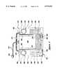
- FIG. 1Bshows the rear of the system console 46, including the rear surface 166.
- the console 46includes a base frame or chassis 168, a sheet metal cover 170 having three sides forming an inverted U-shape, and back cover plate 172 occupying roughly the top two-thirds of the surface 166.
- the bottom one-third of the rear surface 166is occupied by the rear wall 174 of pneumatic drawer module 44 shown in phantom, and the rear wall 176 of electrical power drawer 178 which is also partially shown in phantom and will be later described.
- Rear cover plate 172includes a set 202 of 24 ventilation louvers arranged in three columns.
- Rear wall 176 of power electrical drawer 178includes a set 206 of eight ventilation louvers arranged as shown. Both sets 202 and 206 of louvers allow air to be drawn inside of the console 46.
- Air drawn in through louvers 202circulates internally and eventually exits at exhaust fan 184, while air drawn in through louvers 206 is substantially confined to circulate within the electrical drawer 178 and past the lamp drawer 41 since it is confined by shelf/cover 208 and plenum 212 to be exhausted by ventilation fan 182.
- the main pneumatics supply connection to pneumatics drawer 44is made through a male Schrader quick-disconnect fitting 214 in the lower left rear corner of rear wall 174. Electrical power is provided to the electrical drawer module 178 via electrical receptacle and fuse holder assembly 218. A main on/off electrical power switch 220 for turning the console 46 on or off, is located above receptacle 218.
- the various hardware assemblies and drawers of console 46are constructed in a highly modular, easy-to-assemble and easy-to-service manner described in detail in aforementioned application Serial No. (Attorney Docket No. 4569-00095) entitled "Modular Cabinet For Surgical Control System.”
- the control console 46is the heart and brain of the multi-function microsurgical system 40.
- the system 40supports up to nine switch-selectable modes which are used in either or both anterior segment and posterior segment ophthalmic surgery. These modes are: (1) irrigation only, (2) irrigation/aspiration, (3) phaco (either emulsification or fragmentation), (4) vitrectomy, (5) controlled anterior capsulotomy (CAC), (6) bipolar, (7) scissors, (8) illumination, and (9) intraocular pressure (IOP) control.
- Each modeis automatically integrated into the system 40 in a manner appropriate to the type of operation selected by the operator via keys 52-58.
- Irrigation modeemploys a footpedal on/off control of irrigation. This operating mode is intended for use during an anterior capsulotomy and other anterior segment procedures in which irrigation without aspiration is desired.
- lrrigation/aspiration modeprovides footpedal on/off control over irrigation and linear footpedal control over aspiration. This mode is intended for use in the engagement, stripping and removing of residual lens cortical material in extracapsular cataract extraction and phacoemulsification procedures.
- Phaco modeimplements the phacoemulsification and phacofragmentation functions, which are available for both anterior and posterior segment procedures. Under phacoemulsification procedures, a "fixed phaco" mode is available in which the phaco power and aspiration levels are set via the console controls, and "linear phaco" mode is available in which phaco power is footpedal controlled and aspiration level is determined by the console controls. For phaco fragmentation procedures, a fixed phaco mode controls aspiration via the footpedal.
- Vitrectomy modemakes the vitrectomy function available for both anterior and posterior segment procedures.
- footpedal on/off controlis provided for vitreous cutting and irrigation, while linear footpedal control is provided for aspiration.
- this modeprovides footpedal/on-off control over vitreous cutting and linear footpedal control over aspiration.
- CAC modeprovides footswitch on/off control of a CAC probe, and is explained further in connection with the discussion of FIG. 4D below.
- Bipolar modeprovides on/off control of bipolar power via the footpedal assembly, and is described further in the discussion of FIG. 4D below.
- Scissors modeenables the posterior surgeon to employ a pneumatically driven intraocular scissors in any one of three foot-pedal controlled cutting operations: single cut, variable rate or proportional, which will be explained in more detail later.
- Illumination modeprovides fiber-optic illumination to facilitate viewing the posterior segment during posterior procedures.
- the light source thereofis adjustable from approximately five-percent illumination to full brilliance.
- Automatic lamp switchingprovides back-up illumination if the primary lamp should fail.
- IOP modeprovides precision regulated console-adjusted delivery of filtered air to the eye during posterior ocular pressure procedures. Alternatively this mode can be used to pressurize an irrigation supply to the eye for anterior procedures.
- console 46uses a disposable transparent cassette to collect aspirant during surgery.
- the system 40will automatically secure the cassette via a solenoid-actuated valve, and a vacuum connection will be established at that time.
- the system 40also includes additional features, namely, aspiration prime and irrigation prime in the same manner implemented in the DAISY console. Further, the special repeat reflux procedure is supported by the control console 46 in order to allow a handpiece to be cleared with pneumatic pressure if it becomes clogged with tissue. This reflux feature is available in all anterior modes, and consists of repeated reflux action.
- microprocessor-based control systemdescribed in FIG. 4, enables the various strategies for the control functions to be stored in memory and called upon as required.
- the various components of the surgical systemhave been constructed as separate modules or subassemblies where possible. This approach is evident in the electronics portion and pneumatics portion of the control system 40. Where practical, distinct electrical functions have been placed on their own printed circuit board which is separately addressed by the microprocessor. Similarly, the pneumatics functions have been collected and placed in one drawer module to allow easy installation and replacement.
- FIG. 3shows a plan view of foot controller 240 (also called a footswitch assembly) utilized by the system 40 which has a metal carrying handle 241 and is linked directly to the console 46 with a suitable length of multi-conductor electrical cable 242 which has suitable multi-pin connector 244 at the end thereof that plugs into connector receptacle 190 on the back of the console 46.
- foot controller 240also called a footswitch assembly
- the footswitch assembly 240includes: a large plastic molded housing 246 enclosed with a large rectangular bottom plate 248; having a footpedal 250 which pivots about a horizontal footpedal shaft 252 supported by sintered bronze flange bushing assemblies 254 and 256: left and right vertically arranged side pedals 258 and 260; and left and right top footswitch assemblies 262 and 264 having mushroom heads 266 and 268 and electrical contact blocks 270 and 272, shown in phantom, to signal when the respective top buttons have been pushed.
- Side switches 278 and 280shown in phantom, which may be microswitches or magnetic proximity switches, are actuated and provide electrical signals indicating when their respective side pedals 258 or 260 have been pressed.
- the housing 246includes left and right bunker structures 282 and 284 which rise above footpedal 250 up on which top footswitches 262 and 264 are mounted. Underneath left bunker 282 is located a footpedal posit i on encoder assembly 286 shown schematically in phantom. Assembly 286 includes an optical position encoder 288 which produces two digital signals in a quadrature relationship as the shaft 252 rotates, and a zero reset switch 290. Under bunker 284 is located a detent assembly 294 which may be electrically engaged as desired via detent control solenoid assembly 296 including an electrical solenoid coil 298.
- the side switches 278 and 280 and top footswitches 266 and 268provide on/off control of certain features during selected ophthalmic procedures.
- the left top footswitch 266provides on/off control of bipolar coagulation.
- the right top footswitch 268, via display 50 and buttons 52,may be configured to control the emergency rapid-up feature of the motorized IV pole option or to control some other operating room device via the accessory receptacle 194 on the back c over 166 of console 46.
- the footpedalis used to control irrigation, aspiration, phaco and vitrectomy modes in a manner like that used for the Storz DAISY console.
- the footpedal detentsare now and are provided in the manner described in aforementioned application Serial No.
- FIG. 4Ashows a simplified block diagram of a microprocessor-based electronic control system 320 found in the control console 46 shown in FIG. 1.
- Control system 320includes a microcomputer 322 having a microprocessor 324, volatile (RAM) memory 325, nonvolatile (ROM) memory 326, a VME bus interface circuit or port 328, an interrupt handling circuit or port 330, and an internal control/address/data bus 332 which allows internal communications in conventional fashion between all portions of microcomputer 322.
- a preferred microprocessor 324is a 68000 Series Motorola microprocessor with a clock speed of 12.5 Megahertz and one wait state for handling interrupts, although any other suit able microprocessor could be used.
- Computer 322also includes a 25 Megahertz crystal oscillator 334, a watchdog timer circuit 336, and a chip select and addressing (CSA) section 338.
- the microcomputer 322is located on a single board, called the processor board.
- the microcomputer 322which is located on its own printed circuit (PC) board, communicates with the remainder of the electronic control system 320 via a VME bus 340 consisting of address, data and control lines 342, 344 and 346.
- the VME bus 340is used to communicate with seven other boards within the system 320, namely: the expansion memory PC board 345, the video control PC board 346 which drives the visual display SO, the CAC/bipolar circuit PC board 347, the phaco circuit PC board 348, the lamp control PC board 349, the pneumatic control PC board 350, and the expansion I/O PC board 352.
- the groupings of various functions on distinct PC boardswas done in order to make maintenance simpler. By clustering similar or related functions together on one board, it is possible to reduce diagnostic time and service costs since individual functions not performing correctly may be isolated on a board-by-board basis, and suspect boards may be replaced as needed.
- the processor board 322, the expansion memory board 345 and the video board 346are all conventional purchased items from PEP Modular Computers GmbH of Kaufbeuren, West Germany. The manner in which all of these boards are designed and work from a hardware and operating system perspective is conventional. The manner in which the video board 346 drives the CRT 50 is conventional too.
- the CRT 50 used with the control console 46is preferably a 9-inch diagonal monochrome monitor with standard resolution, although any other suitable two-dimensional display may be utilized such as liquid crystal display or electro luminescent display.
- the lamp control board 349is used to control the components in the lamp drawer 41 which is the source of light for fiber optic light pipe 100 shown in FIG. 1A.
- Pneumatic control board 350is used to control the cassette hardware 356 and the pneumatic drawer hardware 360.
- the cassette hardware 356refers to those input devices such as switches and output devices such as solenoids associated with the aspirant collection cassette 72 shown in FIG. 1A.
- the pneumatic hardwareincludes pressure transducer, a torque motor servo-valve and solenoids.
- Expansion I/O board 352is used to communicate or control the memory key circuit 362, the audio generator circuit 364, which drives speaker 366, the IV pole hardware 368, an optional remote controller 370, and the footpedal assembly 240 of FIG. 2.
- the expansion I/O board 352also is used to interrogate or operate various other input and output devices associated with the control console 46, such as the keypads 52, the indicator lights on secondary panel 60 and connector panel 90 and the accessory relay 372 associated with accessory receptacle 194 shown in FIG. 1A. All user-generated input commands are handled through I/O board 352. To ensure such commands are promptly communicated to the processor 324, board 352 generates an interrupt request (IRQ) signal on line 374 to inform the processor 324 that the I/O board needs to be serviced. The processor also generates an interrupt acknowledge (IRA) signal on line 376. In this manner, user input commands take precedence over lower priority I/O tasks also being handled via VME bus 340.
- IRQinterrupt request
- IRAinterrupt acknowledge
- FIG. 4Bis a detailed block diagram of the CAC/bipolar circuit board and the power amplifier/transformer sections 380 and 382 which it drives with DC level control signals 386 and 388.
- the board 347includes a standard VME bus interface circuit (BIC) 390b, which is interfaced directly to on/off control circuits 392 and 394 and to a multi-stage digital counter 396.
- the digital counter 396is continuously run, and taps are provided at various stages thereof to provide three digital logic level, timebase signals, all of which are square waves having a 50% duty cycle, namely a 120 Hz signal on line 400, a 1 MHz signal on line 401 and a 5 KHz signal on line 402.
- CAC functionis best understood by explaining a few basics about the capsular anterior capsulotomy procedure.
- a pyramidally-shaped tip positioned at a right angle to and near the tip of a microsurgical needlevibrates at a fixed rate, such as 120 Hz, in two dimensions, namely axially and transversely. This cutting action is used to cut the anterior capsule of the eye.
- on/off control 392allows this signal 400 to pass through to line 386.
- Power amplifier 383amplifies digital signal 386 to approximately 2 watts and transformer 384 converts the output signal from the power amp 383 to a square wave which varies between plus and minus 3.5 volts. The amplitude and frequency are fixed.
- the power from the secondary transformer 384is applied to connector 126 on receptacle panel 90 of the console 46.
- a conventional CAC probe from Storzmay be plugged into connector 126.
- the bipolar cautery function implemented by the board 347is conventional, and has been used in the Storz DAISY console several years.
- bipolar cauterya high frequency moderate power signal is applied to electrodes located at the tips of a conventional bipolar probe.
- the high frequency electrical signalis used to cauterize severed blood vessels, incisions and the like.
- a 1 MHz power RF signalis output to connection 120 by RF power amplifier 410 and step-up transformer 412.
- the maximum outputmay be limited to 7.5 watts at 100 ohms.
- the power of the RF signal applied to connector 120is preferably adjustable from zero to 100 percent. In the electronic control system 320, this is implemented in the following manner.
- the bipolar signal applied to connector 120is considered to be at 100 percent power when the RF signal is modulated so as to be on 50 percent of the time and off 50 percent of the time.
- the low level 1 MHz signal 401is pulse width modulated by on/off control 394 using the 5 KHz signal 402 as a time base.
- the signal 402has a 50 percent duty cycle, which means it is on for 100 microseconds and off for 100 microseconds each cycle. This represents 100 percent bipolar power.
- a digital timer circuit 416 within the on/off control 394reduces the on time of signal 402 while increasing the off time, thus resulting in a pulse width modulated (PWM) signal 418 having a duty cycle corresponding to the duty cycle required to achieve the desired power level.
- PWMpulse width modulated
- This signal 418is applied to gate circuit 420 resulting in signal 388 being a PWM composite RF signal which when on oscillates at 1 MHz.
- Signal 388is fed to RF power amplifier 410, whose output drives the primary of transformer 412.
- Transformer 412isolates the amplifier 410 and provides proper output impedance levels at its secondary.
- On/off control block 394thus regulates when the composite RF signal 388 is on, and its effective duty cycle.
- FIG. 4Cshows a detailed block diagram for the phaco circuit 430 forming part of electronic control system 320.
- the phaco circuitincludes another standard VME BIG 390c, which is used to produce a variety of digital control signals including the test command signal CT T a first power command signal Cp P1 a closed loop command signal C CL and a second power command signal C P2 .
- the phaco control moduleincludes a voltage controlled oscillator (VCO) section 434, a power amplifier section 436, a power monitor section 438, an automatic gain control (AGC) section 440, a transformer section 442, a relay control section 444 including relay coil 446 which operates a Form-C electrical contact 447 and a resistor bank 448.
- VCOvoltage controlled oscillator
- AGCautomatic gain control
- the phaco drive circuit 430produces an ultrasonic (US) signal 450 which ranges in strength between 0 and 35 watts at a frequency in the range of 26 KHz to 31 KHz at approximately 5 kilo-ohms.
- This ultrasonic signalis applied to connector 116 of the receptacle panel 90 of console 46.
- a conventional phacoemulsification or phaco fragmentation probemay be provided power by plugging its electrical jack 114 into receptacle 116.
- the phaco drive circuits 430checks itself by having relay section 444 switch the contact 447 to its opposite position, thus applying the US signal from power amplifier 436 to resistor bank 448. Next, circuit 430 switches relay coil 446 off, thus allowing power to flow from amplifier 436 through contact 447 to transformer section 442.
- the dominant resonant frequency of the ultrasonic transduceris determined by monitoring the voltage and currents signals on conductors 460 and 462 as a US test signal VA is swept through frequencies within the range of 26 KHz to 32 KHz.
- processor 324looks for power peaks, among other things, to find the resonant frequency.
- the phaco drive circuit 430enters a drive mode.
- the circuit 430under user commands interpreted by processor 324 and delivered via VME bus 340, drives the VCO section 434 at the dominant resonant frequency and desired power level indicated by commands CF and C P1 , which is passed along as a voltage signal V u to power amplifier 436, where it is amplified and transferred as signal V A to transformer section 442.
- Power monitor section 438observes the voltage and current applied to the primary of transformer section 442, and produces the monitored power signal P M on line 470, which feeds into AGC section 440 where it is compared against the desired power command C P2 .
- FIG. 4Dshows a block diagram of the fiberoptic illumination (FOI) lamp control circuit, which includes the lamp control board 449 shown in FIG. 4A, and the electrical hardware 480 controlled by PC board 349.
- the board 349includes a triac controller 484, a relay driver circuit 486, a threshold level sensing (TLS) circuit 488 an RMS-to-DC converter 490 and 8-bit resolution analog-to-digital converter (ADC) 492.
- TLSthreshold level sensing
- ADC8-bit resolution analog-to-digital converter
- Conventional optoisolatorsare used in circuits 484 and 486 to help prevent electrical noise for these two circuits from being passed to other parts of the electronic control system 320.
- the lamp drawer 41includes two lamps 494 and 495 shown in FIG. 4D which are powered by a low voltage (15 volts RMS) AC signal source 496 which has its power delivered via conductor 497 to triac 498, conductor 499, Form-C relay contact 500 and then to conductor 501 or 502.
- the primary bulb 494is employed to illuminate through a conventional focusing lens 504 receptacle 106 of front panel 90.
- Processor 324provides signals via VME bus 340 to the lamp control board 449 instructing triac controller 484 as to how brightly to turn on the light bulbs 494 or 495. This is accomplished in conventional manner by the timing of the gate signal on line 506 applied to triac 498.
- Isolation transformer 512is used to monitor the light bulb current to determine if the lamp circuit is operating properly. Current passing through either bulb 494 or 495 also passes through the primary of transformer 512, causing a voltage to be developed across its secondary which is delivered by conductor 514 to TLS circuit 488, which produces are output when the sense current exceeds a predetermined threshold level. Processor 324 periodically checks to see if the output of TLS circuit 488 is on, which indicates that the bulb circuit is operating satisfactorily. If this signal should be absent, relay driver 486 energizes relay coil 518 which transfers the Form-C contact 500 so that power from triac 498 is delivered via conductor 502 to the second light bulb 495.
- lamp driver circuit 480automatically switches to the secondary lamp source 495 when the primary bulb 494 fails to operate for any reason.
- electrical contact 520closes and rotation solenoid 522 causes a mirror (not shown) to rotate into position so that light from secondary bulb 495 shines directly into focusing lens 504.
- Isolation transformer 526monitors the voltage on line 499, which is equal to the voltage applied across the light bulb. This voltage signal induces a corresponding current in conductor 528 connected to RMS/DC converter 490 which produces a DC signal on line 530 proportional to the amplitude of the signal on line 528. ADO 492 converts this into a digital value which is transferred via BIC 390d and VME bus 340 to processor 324. Processor 324 periodically examines this value to determine whether fluctuations in the applied voltage level of the bulb are occurring. If they are, processor 324 issues appropriate compensating commands to triac controller 484, thus keeping the effective power applied to the light bulbs constant, to help ensure a constant level of illumination in accordance with the illumination level setting selected by a user via keys 52.
- FIG. 4Eis a block diagram of the electrical control circuitry 540 found on pneumatic control board 350, which as shown in FIG. 4A is used to drive the electrical devices forming part of the cassette hardware 356 and the pneumatic hardware 360.
- the circuitry 540includes a pneumatic control section 542 and a cassette control section 544.
- the BIC 390e and an 8-channel ADC 546are common to both sections.
- Pneumatic control section 542include a solenoid driver circuit 552 and a DAC 554 and a voltage-to-current op amp driver circuit 556.
- Three sets of conductors 558, 560 and 562deliver signals from section 542 to a common connector board 566 located at the pneumatics drawer 44.
- Connector board 566serves as a convenient termination point for three sets 568, 570 and 572 of internal conductors which run between connector board 566 and the actual electrical devices 576 being driven or read.
- the devices 576include a torque motor servo valve 578 and set 580 of solenoids which operate valves and a set 582 of pressure transducers.
- the torque motor servo valve 578is used to provide a proportionally metered flow of pressurized air which is used to create a desired level of vacuum for aspiration or of air pressure for operating microscissors.
- the rate of air flowis proportional to the opening in the valve, which is proportional to the electric current supplied to the torque motor valve 578.
- Processorcontrols this current level by sending appropriate control signals over VME bus 340 to the BIC 390e in board 540 which causes DAC 545 to generate a specified voltage level. This voltage level is converted by op amp driver 556 into an amplified current signal passed along conductors 558 and 568 to servo valve 578. Processor 324 also controls the operation of solenoid valves in the pneumatic system 44 by sending appropriate signals to BIC 390e shown in FIG. 4E, which turns on individual driver circuits, as desired in solenoid drivers circuitry 552. Thus suitable voltage signals (such as 12 volts DC) are applied along individual ones of conductors 560 and 570 to turn on desired ones of the solenoids 580.
- suitable voltage signalssuch as 12 volts DC
- Pressure transducers 582generate low voltage analog signals which are routed up through conductors 572 and 562 to respective individual channels of ADO 546, which read the analog signal levels.
- Processor 324polls ADC 546 periodically through BIC 390e to obtain digital values of the pressures sensed by transducers 582. Further details about the construction and operation of the pneumatics hardware 360 and operation of the pneumatic system are provided below.
- Cassette control section 544includes conventional solenoid driver circuitry 590 and sensor interface circuitry 592.
- Solenoid drive circuit 590provides amplified voltage signals to three solenoids used to operate two position, three-way pneumatic valves that individually control three small pneumatic cylinders used for cassette capture, aspiration pinch and reflex pinch operations.
- the cassette hardware 356includes two level sensing devices 598 and 600 which detect when fluid in the collection cassette 72 has reached predetermined levels one and two corresponding to "cassette nearly full” and "cassette full” fluid levels.
- Hardware 356also includes a Hall effect switch 602 (used to detect the presence of the spring-loaded mechanical lever which is pressed when the collection cassette 72 is fully inserted in slot 70) and the cassette eject switch 76 shown on panel 190 in FIG. 1A.
- Sensor interface 592reads the electrical signals on conductor 604 to determine the states of devices 602 and 76.
- Two channels of ADC 546read the states of level sensing devices 598 and 500 over conductors 608.
- processor 324interrogates sensor interface 592 and ADC 546 to determine the status of sensing devices 598, 600, 602 and 76.
- the level sensing device 598preferably consists of a LED and phototransistor positioned on opposite sides of the cassette 72.
- the level sensing device 600preferably consists of the same type of LED/phototransistor arrangement, but located at a slightly higher level. Further details about the cassette hardware 356 is provided in aforementioned application Serial No. (Attorney Docket No. 456900095) entitled "Remote Control Console For Surgical Control System.”
- FIG. 4Fshows a detailed block diagram of the I/O expansion board 352 and the devices which it drives or reads, namely: the indicator lights on secondary front panel 60 and on connector panel 90 (represented by block 620) and relay 372 for accessory connector 194, the speaker 366, and the primary and secondary front panel buttons 52 and 62, all of which are located in or on the control console 46 (indicated by these devices being to the left of the dashed line 46, which represents the perimeter of control console 46).
- the board 352also drives and/or reads devices in the motorized IV pole assembly 368, the footpedal assembly 240, and the optional remote control console 370, which are all outside of the control enclosure 46.
- the I/O board 352communicates with the VME bus 340 through a VME interface 390f which includes tri-state buffer circuits 626, address and control decoder circuit 628 and 16-bit data latch or register 630.
- the I/O circuitry on board 352also includes four primary control interface circuits, namely accessory control 630, memory key control 632 for memory key 132, audio control 634 for speaker 366, and footpedal control 636.
- Control circuit 636in turn directs the operation of two slave circuits, namely detent control 638 and footpedal decoder 640 which actually communicate with devices in footpedal assembly 240.
- Board 352also includes a conventional serial communications interface circuit 644 which drives and reads in conventional fashion an interrupt generator circuit 646 and a non-volatile memory 645, which preferably is an electrically erasable programmable read only memory (EEPROM).
- Circuit 644includes three conventional integrated circuit (IC) chips, namely a dual universal asynchronous receiver/transmitter (DUART) 647, a dualchannel RS-422 transmitter chip 648, and a dual-channel RS-422 receiver chip 649, all functionally connected as shown in FIG. 4F.
- ICintegrated circuit
- the primary interface circuits 630-638 and the serial communications interface 644communicate with VME bus interface 390f via control signals passed along dedicated control lines 650-656 and 664. Data to be sent to and/or received from circuits 630-638 or communications interface 644 is passed along an internal 16-line data bus 666 connected to data latch 630. Footpedal control 636 communicates with slave circuits 638 and 640 via lines 668 and 670. Each of the primary control circuits and the communications interface 644 contains a data latch circuit for receiving, holding and/or transmitting data to internal data bus 666.
- Address and control decoder 628upon receipt of commands from processor 324 via VME bus 340, decodes the command and address signals on lines 342 and 343, and in accordance with the decoded instructions distributes the desired control signals and/or via lines 667 commands data signals to the control interface circuit 630-636 or 644 which the processor 324 desires to address.
- the control interface circuits 630-636have no intelligence and do not on their own seek to communicate with processor 324. Instead, processor 324 just periodically writes or reads data to these control circuits.
- the communications interface 644has two devices connected to it which have intelligence, namely microcontroller 673 associated with the two front panels 48 and 60 on console 46 and microcontroller 675 associated with optional remote controller 370.
- Serial communications interface 644converses with the microcontrollers 673 and 675 using the well-known RS-422 communications protocol at a suitable data rate, such as 9600 baud. Whenever either of these two microcontrollers has information to be sent to processor 324, it serially sends a byte of information to the communications interface 644 which in turn automatically causes an interrupt to be generated.
- Communications interface 644is identified as the source of the interrupt, the interrupt is acknowledged via line 376, and the processor 324 causes data serially communicated to the DUART 647 by the microcontroller to be loaded into the data latch 630, and then via VME bus 340 reads the data from latch 630 in one of its next I/O cycles.
- Microcontroller 673has its own internal oscillator and micro program. It continuously monitors all of the buttons 52 and 62 found on front panels 48 and 60 of the control console 46 to determine whether they have been depressed. The buttons are electrically arranged in a matrix of row and columns, and by interrogating each position of the matrix the state of all the buttons is determined.
- the microcontrolleradvises the processor whenever a button is pressed, and keeps periodically advising the processor 324 of this fact for as long as the button remains pressed.
- Microcontroller 673also monitors, as part of the aforementioned matrix of buttons, the status top buttons 270 and 72 and side pedals switches 278 and 280 within the footpedal assembly.
- the microcontrollers 673 and 675are provided in order to ensure that the main processor 324 is apprised of changes in status at the front panel console or remote control console virtually immediately for a very quick response to operator requests. In other words, all the routine functions which need not be performed quickly by the main processor 324 are made to wait while processor 324 responds to an interrupt and reads the data from the microcontroller and puts it into a table in main memory 325 one byte at a time. In main memory, a table listing the states of all the buttons on the main console and the remote control console is kept. The microcontrollers 673 and 675 only advise the main processor 324 of changes in the state of any of the buttons. In this manner, communications between the microcontrollers 673 and 675 are handled far more efficiently than updating the entire table each time an interrupt is generated.
- Microcontroller 675operates in the same manner as microcontroller with respect to the matrix of buttons it monitors.
- the remote control console 370also contains a keyboard interface circuit almost identical to interface circuit 680. This interface circuit is described in detail in application Serial No. (Attorney Docket No. 4569-00093) entitled "Remote Control Console For Surgical Control System.”
- Communications interface 644also reads and writes data to EEPROM 645 in conventional fashion.
- EEPROM 645is provided so console 46 can store, in a non-volatile manner, any user-programmed default values, configuration codes, calibration data and/or any other pertinent parameters which may be entered in by the user.
- the accessory control 630contains: a plurality of memory latches and indicator light driver circuits dedicated to driving the indicator lights 620 on connector panel 90 and secondary panel 60; a plurality of memory latches, relay driver circuits, sensing circuits and an optical position decoder, all of which are dedicated to sending control signals to and receiving information from motorized IV pole hardware 368; and a latch and relay driver for operating relay 372.
- a relay driving signalis applied to line 662, relay coil 372 is energized, which closes a normally open contact and thus completes the circuit available on lines 664 connected to the connector receptacle 194 shown in FIG. 1B.
- the details of the electrical devices and circuits in the motorized IV pole 368are described in application Serial No. (Attorney Docket No. 4569-00097) entitled "Motorized IV Pole Assembly," and thus need not be described here.
- the audio control circuit 634is of standard design, and uses a conventional programmable sound generation circuit on a large scale integration (LSI) chip to produce the various tones at various amplitudes used to indicate device operation and provide audio error signals to the console user.
- the output signal from this chipdrives a separate conventional low-power audio amplifier chip, whose output is connected to and drives speaker 366.
- a suitable sound generatoris available from Microchip Technology, Inc. of Chandler, Ariz. as Model No. AY8930.
- One of the unique features provided by control console 46is the user of select various tones and amplitudes for the selected tones to represent different conditions or states that the control system 40 may be placed in by the surgeon. A further description of this aspect of the control system 40 is provided in aforementioned application Serial No. (Attorney Docket No. 456900091) entitled "Control System For Ophthalmic-Surgical Instruments.”
- the detent control 638provides positive and negative 24 volt DC power signals on lines operate the detent solenoid 698.
- a momentary +24 VDC signalextends the armature of solenoid 698 while a momentary -24 VDC signal causes it to retract.
- Conventional magnetic and/or mechanical detents built into solenoid 698hold its armature in the last position the signals on lines 668 placed it in.
- Footpedal decoder 640receives low-voltage quadrature signals over conductors 680 from encoder 288, and a low-voltage digital signal on line 682 from zero switch 290. Switch 290 is released whenever footpedal 250 is moved more than two degrees from its spring-returned position, that is, the position pedal 250 is in when it is not pressed at all.
- bi-directional multiple stage digital counter 684 within decoder circuit 640is held in a reset state. As soon as signal 682 goes to its opposite state, counter 684 is allowed to operate under the control of the quadrature signals on lines 680 which increment or decrement the counter with each pulse.
- the accumulated count in counter 684reflects the true angular position of footpedal 250.
- Processor 324periodically (once every 50 milliseconds) reads the value in counter 684 by sending appropriate control signals to bus interface 390f so that counter 684 can send its present count to data bus 666, where it is held by latch 630 until read by the processor 324 via VME bus 340.
- top button switches 270 and 272 and the side pedal proximity switches 278 and 280 of the footpedal assembly 240are also read through microcontroller 673, which as previously explained serially transmits information to communications interface 644, through internal bus 666, bus interface 390f and VME bus 340 to processor 324.
- FIG. 5A. Schematic Diagram of Pneumatic System
- FIG. 5is a detailed pneumatic schematic diagram of the pneumatic control system 43 of the present invention. All of the components, except for the supply line 700 and Schrader quick-disconnect coupling 702 shown in the upper left-hand corner of FIG. 5 are located within or on the drawer 44, which as shown in FIG. 1A, is located at the back right side of the console 46.
- the pneumatic system 43includes an air pressure regulator section 706, an IOP system 708, a vitrectomy cutter control circuit 710, a solenoid valve manifold section 712 with six valves which control a set 716 of four springreturned pneumatic cylinders 717-720 and two pilot operated valves 722 and 723; a proportional servo valve 578 including valve body 724 and a torque motor operator 725, a high-speed solenoid valve 726, and an air-to-vacuum conversion means namely venturi 730 with exhaust muffler 731.
- the system 43has only one pneumatic Input source which is through the hospital grade Schrader quick-disconnect coupler 214 connected to an internal main supply line 732.
- Any suitable source of pressurized, filtered, dry gas suitable for surgical usesuch as air or nitrogen may be provided to the system 43, such as by a hospital air supply system or by a pressurized storage tank
- the system 43requires that supply input pressure be at least 80 psig and is preferably no more than 100 psig.
- the system 43only has four fluid outlet ports which extend to the perimeter of console 46. Only eight outlet lines extend outside of drawer 44.
- the four outlet ports which extend to the console perimeterare routed by flexible tubing to the cassette area of connector panel 90, where they are attached to and become part of the vitrectomy connector 146 from the vitrectomy control circuit 710, at the IOP connector 150 from the IOP system 708, the scissors connector 156 from the second pilot-operated valve of set 718, and the aspiration connector 734 which extends from the air-to-vacuum converter 730 via pneumatic tubing line 736.
- the four linesconstitute four of the eight outlet lines which extend outside the drawer 44. The remaining four outlet lines go to the air-actuated springreturned cylinders 716-720.
- the systemalso includes a set 582 (see FIG.
- Section 706includes: a conventional main pressure relief valve 750 preferably set to 125 psig to protect against air supply overpressure conditions; a very fine gauge filter assembly 752 with a replaceable submicron filter cartridge (0.1 micron filter preferred); the pressure transducer 741; and a set 754 of pressure regulator valves 756, 758, 760 and 762 arranged in series as shown and preferably set respectively to 75 psig, 70 psig, 60 psig and 190 mmHg.
- Pneumatic tubing 764extends from the filter 752 to the main pressure regulator 756.
- Pneumatic lines 766, 768, 770 and 772respectively extend from the downstream side of regulators 756, 758, 760 and 762 to other sections of system 43.
- the pressure regulating means 750-762may be of the adjustable type or may be of fixed pressure rating type. If of the adjustable type, they are preferably adjusted to the desired pressure setting when system 43 is first assembled and tested, and then their adjustment screws locked tight before being put into surgical use.
- the IOP system 708includes pneumatic lines 766-788 and three two-way, two-position solenoid-operated control valves, namely valves 792, 794 and 796.
- the system 708also includes an accumulator 802, a submicron filter 804 and the pressure transducer 742.
- the submicron filter 804is normally provided as part of the disposable tubing set used by ophthalmic surgeons.
- the purpose of the IOP systemis to provide a precisely controlled supply of low flow, low-pressure air, which is required in certain ophthalmic posterior segment surgical procedures, or can be used to pressurize a bottle of irrigating solution also often used during ophthalmic surgery.
- the maximum pressure that can possibly be delivered by the IOP systemis set by regulator 762, which can be raised or lowered as desired by adjusting the regulator.
- a spring-loaded mechanical regulatorsuch as regulator 762, is not capable of providing the fine and readily adjustable control of low-flow, low air pressure desired from an IOP system.
- the present inventionuses solenoid valves 792-796 in combination with accumulator 802 to achieve precision adjustment of IOP pressure. Via transducer 742, the IOP output pressure at connector 150 is monitored on line 780, and solenoid valve 792 and 794 are cycled as will be explained below, to obtain the desired level of pressure.
- the IOP system 708employs the accumulator 802 to smooth out any pulses on the line 780, while the submicron filter 804 ensures that contaminants do not enter the surgically used air stream provided by IOP system 708 via connector 150.
- valve 792is called the IOP charge valve, since it allows pressure to build up in the IOP system, while the valve 778 is called the IOP exhaust valve, since it allows pressurized airs to flow through metering orifice 795 to atmosphere, thus depressurizing the IOP system.
- Valve 796is called the IOP shut-off valve since only when its solenoid 797 is energized is air able to flow from the pressure source (i.e., line 772) through to connector 150.
- the size of the opening in fixed orifice 795is selected to be approximately one-half the size of the passageway through the valve 792 and through the valve 794.
- the IOP systemhas five distinct control states or modes, which depend upon the status of the valves 792-796, and which are listed in Table 1 below.
- first modealso called the "exhaust” mode
- charge valve 792is closed and exhaust and shut-off valves 794 and 796 are opened. This allows all pressure above atmospheric to escape through metered orifice 795 and exhaust valve 794.
- second or “fast charge” modecharge valve 792 is opened and exhaust valve 794 is closed, while the shut-off valve 796 remains opened. In this mode, pressure builds in lines 766-788 at a maximum rate allowed by the size of the components and lines.
- the third or “slow charge” modehas all three valves 792-796 opened. In this mode, roughly half of the incoming pressurized air on line 772 is able to escape directly to atmosphere via opened valve 794. Thus the rate of increase of air pressure is significantly slower than in the fast charge mode.
- the system 708enters its fourth mode, which may be called the "hold” mode. Valves 792 and 794 are closed while shut-off valve 796 remains opened. If the desired air pressure level should be above the actual air pressure level by some margin (e.g., 2 mmHg or more), this will be sensed by transducer 742 and processor 324 will place system 708 in the exhaust mode to reduce the air pressure.
- some margine.g. 2 mmHg or more
- the fifth or “power-off” modeis really an uncontrolled state where all electrical power to the IOP system 708 (or at least to its solenoid valves 792-796) is turned off or otherwise lost. For example, in the event of a power failure, IOP system 708 and its electrical devices will be immediately de-energized. In this "power-off" mode, valve 796 closes, which helps preserve pressure in lines 780-788 for as long as the charge in the accumulator remains. Eventually the pressurized air in lines 780-788 may leak out through the pneumatic lines connected to connector 150.
- the IOP system 708 of the present inventionhas the advantage of maintaining the intraocular pressure in the eye for a greater length of time in comparison to previous systems which, upon power failure, automatically bleed down the IOP pressure lines.
- an accumulatoris provided at all, it is located on the upstream side of a valve that closed upon power failure, which allowed the accumulator to bleed out upon electrical power outage.
- the system 708 of the present inventionpreserves the maximum amount of air in event of electrical power outage conditions.
- locating the accumulator close to connector 150 and downstream of the air pressure regulating valves 792 and 794helps ensure that the accumulator will best be able to dampen out pulsations or pressure variations inherently created in a low-pressure pneumatic pressure control system using on-off valves for charging and exhaust functions.
- the processor 324monitors the output pressure of the IOP system 708 via transducer 742 and interface circuitry 540 shown in FIG. 4E, and selects for IOP system the most appropriate mode needed to produce or maintain the IOP output pressure as close as possible to the desired pressure setting selected by the user on console 46.
- the userselects the desired IOP pressure via one of the pairs of up/down buttons 58 front display 48 when the menu for IOP system is displayed.
- the IOP system 708thus operates under the control of processor 324.
- the control exercised over IOP system 708 by processor 324can be best understood by way of the following example. Assume that a desired IOP pressure of 80 mmHg has just been selected by the user of console 46, that the IOP pressure is presently 0aa mmHg, and that IOP system 708 is currently in its exhaust mode. To reach the desired level as quickly as possible without overshoot, processor 324 initially places system 708 in its fast charge mode.
- processor 324switches system 708 to its slow charge mode, which causes pressure to rise at roughly half the rate of the fast charge mode.
- processor 324switches system 708 to its hold mode. Tests show that the system 708 does not exhibit any significant overshoot. However, if it did, the processor 324 would enter the exhaust mode to reduce the pressure slowly. As the actual pressure on line 780 reached the desired level, the processor 324 once again would switch to the hold state.
- processor 324obtains pressure readings obtained from transducer 384 at predetermined intervals of time (such as every 50 milliseconds), and as necessary processor 324 makes appropriate changes of mode then. In this manner, the IOP system 708 exhibits excellent response with very little if any overshoot. Further, tests show the use of accumulator 802 downstream of shutoff valve 696 reduced 4 mmHg pulsations exhibited by at least one prior art pneumatic system that used on/off charge and exhaust valves, to almost 0 mmHg.
- the vitrectomy control section 710delivers controlled pressure pulses to connector 146 on panel 90 of console 46.
- Conventional Storz MicroVit vitrectomy probes 140include a guillotine-type cutter and are connected by an 80-inch-long medical-grade polyethylene tube 810 having an internal diameter of one-sixteenth inch to connector 146.
- the Storz DAISY consoleincluded an identical section 710, except that the separate 60 psi regulator 760 was not provided there. In both the DAISY console and console 46 shown in FIG. 1A, the cutting rate is selected by the user either (by a potentiometer) or buttons 58 when the vitrectomy procedure menu is displayed.
- the two-position, three-way solenoid-actuated, spring-returned control valve 812is cyclically energized and de-energized at a rate equal to the desired vitrectomy cutting speed, provided that the user has pushed the appropriate button on footpedal assembly 240 (shown in FIG. 3) to initiate this cutting action.
- the regulator 760has a maximum setting of 60 psig in order to avoid creating too much residual pressure at the higher cutting rates. At cutting rates above 690 cpm, tests show that the off time between pulses is so short relative to the amount of air resident in lines 810 and 814 that the air pressure does not have an opportunity to completely bleed off to atmosphere through valve 812 when de-energized. Thus pressure can build up.
- the pressurecan be kept from building up to undesirable levels (pressure greater than 3 psig). Also, it is desirable to keep the time that valve 812 is closed short enough so that the pressure never rises above 40 to 45 psig, and preferably only rises to about 31 psig, which is all the pressure that is required to completely close a Storz MicroVit probe under normal operating conditions.
- the valve manifold section 712includes six two-position, three-way, solenoid-actuated, spring-returned, valves, namely valves 818-828. Valves 818-822 and 826 drive spring-returned cylinders 717-720 as shown in FIG. 5.
- the cylinders 717 through 720are respectively used for the following functions: cassette capture (which is actuated when the "cassette present" switch 602 indicates a cassette 72 has been fully inserted into slot 70); irrigation pinch assembly 76; aspiration pinch-off (squeezes section of pliable aspiration tubing running along top side of cassette 72); and reflux (squeezes aspirant tubing section adjacent to aspiration pinch-off tubing section to create the reflux action after the aspiration pinch-off is already actuated).
- Valve 824drives pilot line 830 leading to the pilot operator 832 of two-position, four-way, spring returned directional valve 722.
- Directional valve 722directs pressurized proportional air flow from the servo valve 578 either to the venturi 730 (in order to produce a desired vacuum/aspiration level in tubing 736) or to line 836 and metered orifice 838 (which the bleeds line 840 to atmosphere). Note that when the solenoid of valve 824 is energized, valve 722 diverts a pressurized air from servo valve 578 to line 840, which delivers it to scissors connector 156 as well as orifice 156.
- the five solenoids 818-826 and cylinders 718-724, the servo valve 578 and the directional valve 722 as shownare all used in the Storz DAISY console.
- Air-to-vacuum converter 730 and its muffler 731 and transducer 744are also employed in the Storz DAISY console.
- valve 828(identical to valve 824) which pressurizes pilot line 848 connected to the pilot operator 850 of two-position three-way, spring return directional valve 723, that makes it possible to provide the three different scissors modes, including the high-speed multi-cut mode, through a single connector port 150, as will now be further explained below.
- line 840was connected directly to connector 156 for driving conventional microscissors in either a proportional cut mode or a single cut mode.
- the depression of the foot pedal more than a predetermined amounte.g., 5 degrees while in the microscissors mode caused the servo valve 724 to turn on completely once for a brief period of time (several tens of milliseconds) which caused the spring-biased scissors to close and then open when the pressure subsided as a result of valve 224 returning to its closed position.
- the proportional cut modethe air pressure provided at connector board 156 varied in accordance with the amount which a user depressed the foot pedal on the footswitch assembly.
- variable size orificei.e., the variable size orifice in servo valve 724
- fixed size orificei.e., orifice 838
- the pneumatic control system 43 of the present inventionemploys the same techniques for operating its single cut mode and proportional mode for the microscissors.
- the solenoid of control valve 828is left de-energized, so that there is a fluid passageway between line 840 and connector port 156 through valve 723.
- the servo valve 724especially in combination with the air pressure dividing circuit just described, could not provide a high-speed pulsating signal (between 50 and 200 cycles per minute (cpm)) desired by some ophthalmic surgeons for microscissors operation.
- the Storz DAISY consoleis only capable of cutting at approximately 35 to 40 cpm maximum.
- control valve 726when energized allows pressurized air from line 768 to flow through to line 850 connected to directional valve 723.
- line 850is dumped to atmosphere.
- the solenoid of valve 828is energized, which places pilot air on line 848, causing valve 723 to shift to its actuated position so that line 850 is tied to connector port 156.
- processor 324causes control valve 726 to cycle at the desired rate selected by the user via console 46.
- FIG. 4Eshows the control circuitry used to drive these solenoids, which have been previously explained.
- transducer 741 connected to line 764monitors the main supply pressure from line 732 in order to determine whether it is adequate for all intended purposes to which the pneumatic system 43 may be put.
- the pressure sensing meansinstead of transducer 741 pressure switch.
- the pressure in line 764 in the DAISY consolecould momentarily drop below the pressure switch setting, causing an indication through the pressure switch of low supply air pressure. In the DAISY console, this produced a warning to the surgeon of low air pressure.
- transducer 741is an analog signal whose magnitude corresponds to the actual dynamic pressure within about one psi or less. Accordingly, use of transducer 741 allows processor 324 to take accurate readings of the pressure on line 764 to determine whether or not it has fallen below the acceptable minimum level of transient pressure in the range of 60-64 psi. Further, with its precision time base, processor 324 is also able to monitor with accuracy the length of time for which pressure transducer 741 is low.
- processor 324when processor 324 sees the pressure reading from transducer 741 dip below the minimal continuously acceptable level (e.g., 72 psig), it watches to determine whether the actual pressure reading drops below a predetermined "critical" level (e.g. 60 psig). If it does, a low pressure warning is generated since such pressures are normally not encountered even upon initiation of high-levels of aspiration/vacuum. If however, the transient reduced pressure indicated by transducer 741 is not below this critical level, but is below the continuous acceptable level, the processor 324 monitors the length of time that the reading stays below the acceptable level (72 psi). If this continues more than a predetermined length of time, such as 200 milliseconds, then a low pressure warning is generated.
- a predetermined "critical" levele.g. 60 psig
- processor 324does not generate the low pressure warning-
- this aspect of the present inventionavoids nuisance occurrences of a safety procedure (e.g., the warning to the surgeon) during non-hazardous transient pressure situations, while still providing the capability of warning the surgeon when possibly serious low-pressure conditions exist in pneumatic control system 43.
- FIGS. 6 and 7show plan and side cross-sectional views of the pneumatics drawer assembly 44 which holds most of the pneumatic system 43.
- Drawer 44includes: a flat bottom 880 and side walls 882 and 884; a front drawer or face wall 886 provided with a painted cover plate 888 fastened thereto and extending somewhat beyond the side walls; and a rear wall structure 890 having two back wall portions 892 and 894, and an intermediate side wall portion 896 extending between back wall portions 892 and 894.
- the main drawer chamber section 900is filled with various pneumatic components, conventional tubing and electrical wires (not shown) for the solenoids, while the secondary drawer portion 902 in the rear of drawer 44 contains only the vitrectomy solenoid valve 812 on its own support shelf 904, the connector board assembly 566 and a limited amount of pneumatic tubing.
- Side walls 884 and 896are provided with flanges 906 and 908 which support the shelf 904 and printed circuit (PC) board assembly 566, which are both held on by screws 910 or other suitable fastening means.
- the structural part of drawer 44may be made from any suitable material such as sheet metal, molded plastic, or the like.
- FIGS. 7, 8 and 9are cross-sectional views taken along lines 7--7, 8--8 and 9--9 of FIG. 6, which better illustrate the details of the construction of PC board assembly 556 and support shelf 904.
- the connector board 566does not contain any electronic circuitry, but instead is simply used as a convenient termination point for the Internal electrical wires 568-570 and 572 connected to the torque motor valve 578, the solenoids 580 and pressure transducers 582 used in the pneumatics drawer 44.
- Connector board assembly 566includes a conventional PC circuit board 916 having metallic conductor traces as needed, two conventional electrical multiple-pin, straight-line connector receptacles 918 and 920 mounted on the upper face 922 of the PC board which receive mating connector plugs 924 and 926, the set 582 of pressure transducers 741-745 arranged in a line, and a set 930 of conventional single-screw pressure terminal-to-PC-board connectors used to receive the individual conductors 578 and 570 from solenoid valve 578 and the set 580 of solenoids (see FIG. 4E).
- the transducer conductors 572are wired directly on the PC board to the receptacle 918.
- the individual terminals 930are wired directly on the PC board to connector receptacle 920.
- all of the transducer conductors 552 running between pneumatics drawer hardware 360 and the pneumatics control PC board 350run through connector 918, while all the torque motor conductors 558 and solenoid conductors 560 run through connector 920.
- PC connector board 566One important benefit of PC connector board 566, then, is that it can be pre-assembled with all its components on it well ahead of the actual need for the board. Thus PC board assemblies 556 can be stockpiled as needed for manufacturing purposes. Once board 556 is attached to flanges 906 and 908 in drawer 44, it is an easy matter to hook color-coded electrical wires (not shown) from the solenoid valves to terminals 930, and to plug in connector plugs 924 and 926 to complete the electrical connections to the pneumatics drawer assembly. Just prior to the board 556 being fastened to the flanges, the pneumatic lines 736, 764, 784 and 840 are attached to the transducers, as shown in FIG. 8.
- the support shelf 904 for vitrectomy solenoid valve 812is shown.
- the shelfhas a U-shaped cross section, as best seen in FIG. 9, and the valve 812 is mounted on vibration-dampening material 936 which is preferably blow-molded foam material with adhesive on all sides thereof.
- the material 936is made from one eighth inch mounting tape doubled over for double thickness (i.e., dimension 938 is one-quarter inch).
- Material 936may be double-sided adhesive-backed mounting tape available from Minnesota, Mining and Manufacturing Company of Minneapolis, Minn. under adhesive tape Part No. 4408.
- the high-speed control valve 726 for the multi-cut scissors operationis also mounted using this same material 936 on top of a sheet metal support bracket 940 having a U-shaped cross section as best seen in FIG. 9.
- the U-shaped b racket 940 shown best in FIGS. 7 and 9is fastened by screws and nuts 942 or the like to drawer bottom 880. Also mounted on the upper surface 944 of support bracket 940 is the pilot-operated, two-position, three-way spring returned directional valve 723, with its pilot operator 850 overhanging the side of stanchion 940. Positioned underneath support bracket 940 is a transparent plastic protective rectangular housing 950 for the silicone rubber bladder which serves as accumulator 802 shown in phantom within housing 950. Line 782 is connected to a conventional pneumatic fitting assembly 954 attached to housing 950 and to bladder 802 within the housing.
- the bladderis typically made of very pliant material such as natural rubber because it must be able to expand at very low pressures reliably and repeatably without tearing.
- Protective housing 850makes sure the bladder is not inadvertently scratched or punctured by other objects during the assembly of or use of pneumatics drawer 44.
- the arrangement of various pneumatic components within the large chamber 900 of drawer 44is designed to maximize efficient use of space, which allows the drawer 44 to be made smaller. Yet the large section 900 of drawer 44 is not so crowded that it is difficult to make the various connections shown.
- a number of the devices, fittings, and tubing sectionscan be connected together before they are mounted or fastened into the enclosure 44 by screws, adhesives or other suitable fastening means.
- the pressurized air supplycomes in on hospital grade Schrader fitting 214 and runs through main filter 752 near the face plate 888 the drawer and then to the four regulators 756-762 arranged in a row.
- valve manifold assembly 712 including valves 818-828reduces the space requirements so that virtually all of the other control components can readily fit within the small volume of section 900.
- the size of the draweris approximately 13.5 inches deep (i.e., the distance between the two parallel front and back wall portions 886 and 892), and 8.4 inches wide (i.e., the distance between the upstanding parallel side walls 882 and 884).
- the total height of the draweris less than 4.0 inches. The drawer thus can easily fit within the larger cabinet of control console 46, without taking up much room.
- FIG. 6shows all of the eight pneumatic lines which exit the drawer 44. These connections are all conventional quick-disconnect pneumatic fittings for 1/16 inch ID or 1/8 inch ID tubing. In the preferred embodiment, fitting Model Nos. SMC-01 and No. SMC-2 from Colder Products, of St. Paul, Minn. are used.
- each of the pneumatic lines on which quick-disconnect fittings are usedhas been marked with an "X". All of the eight output lines from drawer 44 have quick-disconnect fittings on them are appropriately marked by reference numerals with the suffix "C" in FIG. 5.
- the vitrectomy control section 710includes solenoid valve 812 whose output line is tubing line 814. This line extends outside of drawer 44 to connector 146 on the connector panel 90 of console 46. This line 814 is broken by quick disconnect connector assembly as shown by the "X" identified by reference numeral 812C.
- the line 780 of IOP section 708includes quick-disconnect coupling 780C.
- control devices used within the presently preferred embodiment of pneumatics drawer assembly 44are conventional parts purchased from commercial suppliers of such devices.
- the followingis a Table listing a number of the more important devices by reference numeral used in the foregoing description, as well as the company from which such parts are available.
Landscapes
- Health & Medical Sciences (AREA)
- Heart & Thoracic Surgery (AREA)
- Vascular Medicine (AREA)
- Engineering & Computer Science (AREA)
- Anesthesiology (AREA)
- Biomedical Technology (AREA)
- Hematology (AREA)
- Life Sciences & Earth Sciences (AREA)
- Animal Behavior & Ethology (AREA)
- General Health & Medical Sciences (AREA)
- Public Health (AREA)
- Veterinary Medicine (AREA)
- Surgical Instruments (AREA)
Abstract
Description
TABLE 1 ______________________________________ MODES OFIOP SYSTEM 708 VALVE FUNCTION AND STATE Mode Mode Charge Exhaust Shut-off No. NameValve 792Valve 794Valve 796 ______________________________________ 1 exhaust closed opened opened 2 fast charge opened closed opened 3 slow charge opened opened opened 4 hold closed closed opened 5 power-off closed opened closed ______________________________________
TABLE 2 ______________________________________ Ref. No(s). Brief Name Model No. or Part No./Source ______________________________________ 528 servo valve No. 100-521-1 Hydraulic Servo Controls, Inc. Buffalo,New York 712 valve manifold No. NVJ100 SMC Pneumatics, Inc. Indianapolis,726, 812 control valve, No. NZ 3125-0151BG (12 VDC) three-way SMC Pneumatics, Inc. Indianapolis, Indiana Indiana 730 venturi No. 33-S K & K Engineering, Inc. Wheeling, Illinois 741-744 pressure transducers No. PC134 Series Microswitch, division of Honeywell Freeport,Illinois 752 air filter, submicron No. 9900-05-BK Balston Filter Lexington,Massachusetts 762 regulator, low press. No. R06-131-RNKA Norgren Corp. Littleton, Colorado 792-794 control valve, Mini-mizer No. M3E1 two-way Humphrey, Inc. Kalamazoo,Michigan 796 control valve No. ET-2 (12 VDC) Clippard lnstrument Laboratory, Inc. Cincinnati,Ohio 802 accumulator 3-inch Gordon Goodman Bladder Custom Service Labs of New Jersey Inc. North Bergen, New Jersey 818-826 control valve, No. NVJ114-6MZ three-way SMC Pneumatics, Inc. Indianapolis, Indiana ______________________________________
Claims (6)
Priority Applications (1)
| Application Number | Priority Date | Filing Date | Title |
|---|---|---|---|
| US09/201,318US5979494A (en) | 1989-10-27 | 1998-11-23 | Pneumatic controls for ophthalmic surgical system |
Applications Claiming Priority (4)
| Application Number | Priority Date | Filing Date | Title |
|---|---|---|---|
| US42823989A | 1989-10-30 | 1989-10-30 | |
| US08/127,921US5417246A (en) | 1989-10-27 | 1993-09-27 | Pneumatic controls for ophthalmic surgical system |
| US08/448,642US5857485A (en) | 1989-10-27 | 1995-05-23 | Pneumatic controls for ophthalmic surgical system |
| US09/201,318US5979494A (en) | 1989-10-27 | 1998-11-23 | Pneumatic controls for ophthalmic surgical system |
Related Parent Applications (1)
| Application Number | Title | Priority Date | Filing Date |
|---|---|---|---|
| US08/448,642DivisionUS5857485A (en) | 1989-10-27 | 1995-05-23 | Pneumatic controls for ophthalmic surgical system |
Publications (1)
| Publication Number | Publication Date |
|---|---|
| US5979494Atrue US5979494A (en) | 1999-11-09 |
Family
ID=23698066
Family Applications (4)
| Application Number | Title | Priority Date | Filing Date |
|---|---|---|---|
| US08/127,921Expired - LifetimeUS5417246A (en) | 1989-10-27 | 1993-09-27 | Pneumatic controls for ophthalmic surgical system |
| US08/449,408Expired - LifetimeUS5549139A (en) | 1989-10-27 | 1995-05-23 | Pneumatic controls for ophthalmic surgical system |
| US08/448,642Expired - LifetimeUS5857485A (en) | 1989-10-27 | 1995-05-23 | Pneumatic controls for ophthalmic surgical system |
| US09/201,318Expired - Fee RelatedUS5979494A (en) | 1989-10-27 | 1998-11-23 | Pneumatic controls for ophthalmic surgical system |
Family Applications Before (3)
| Application Number | Title | Priority Date | Filing Date |
|---|---|---|---|
| US08/127,921Expired - LifetimeUS5417246A (en) | 1989-10-27 | 1993-09-27 | Pneumatic controls for ophthalmic surgical system |
| US08/449,408Expired - LifetimeUS5549139A (en) | 1989-10-27 | 1995-05-23 | Pneumatic controls for ophthalmic surgical system |
| US08/448,642Expired - LifetimeUS5857485A (en) | 1989-10-27 | 1995-05-23 | Pneumatic controls for ophthalmic surgical system |
Country Status (1)
| Country | Link |
|---|---|
| US (4) | US5417246A (en) |
Cited By (65)
| Publication number | Priority date | Publication date | Assignee | Title |
|---|---|---|---|---|
| US6290690B1 (en) | 1999-06-21 | 2001-09-18 | Alcon Manufacturing, Ltd. | Simultaneous injection and aspiration of viscous fluids in a surgical system |
| EP1199053A1 (en)* | 2000-10-20 | 2002-04-24 | Nidek Co., Ltd. | Vitreous surgical apparatus |
| US20020082793A1 (en)* | 1997-01-22 | 2002-06-27 | Kadziauskas Kenneth E. | Micro-burst ultrasonic power delivery |
| US6575990B1 (en)* | 1999-10-21 | 2003-06-10 | Medical Instrument Development Laboratories, Inc. | High speed vitreous cutting system |
| US20030199787A1 (en)* | 2002-04-23 | 2003-10-23 | Jeffrey Schwindt | Pneumatic circuit |
| US6723065B2 (en)* | 1999-12-22 | 2004-04-20 | Makoto Kishimoto | Intraocular surgical apparatus |
| US20040092922A1 (en)* | 2002-10-21 | 2004-05-13 | Kadziauskas Kenneth E. | Modulated pulsed ultrasonic power delivery system and method |
| US20040092921A1 (en)* | 2002-10-21 | 2004-05-13 | Kadziauskas Kenneth E. | System and method for pulsed ultrasonic power delivery employing cavitation effects |
| US20050054971A1 (en)* | 2003-07-14 | 2005-03-10 | Steen Mark E. | System and method for modulated surgical procedure irrigation and aspiration |
| US20060078448A1 (en)* | 2004-10-11 | 2006-04-13 | Holden Hugo R | Phacoemulsification machine with post-occlusion surge control system and related method |
| US20060079788A1 (en)* | 2001-11-20 | 2006-04-13 | Anderson David L | Resonant converter tuning for maintaining substantial constant phaco handpiece power under increased load |
| US20060089526A1 (en)* | 2004-10-21 | 2006-04-27 | Medical Instrument Development Laboratories, Inc. | Self-sealing closure for an ophthalmic cannula |
| US20060089607A1 (en)* | 2004-10-22 | 2006-04-27 | Medical Instrument Development Laboratories, Inc. | Ophthalmic cannula insertion tool and method |
| US7077820B1 (en) | 2002-10-21 | 2006-07-18 | Advanced Medical Optics, Inc. | Enhanced microburst ultrasonic power delivery system and method |
| US20060195077A1 (en)* | 2002-10-21 | 2006-08-31 | Advanced Medical Optics Inc. | System and method for pulsed ultrasonic power delivery employing cavitational effects |
| US7169123B2 (en) | 1997-01-22 | 2007-01-30 | Advanced Medical Optics, Inc. | Control of pulse duty cycle based upon footswitch displacement |
| US20070260200A1 (en)* | 2006-05-05 | 2007-11-08 | Alcon, Inc. | Phacoemulsification tip |
| EP1857128A1 (en) | 2006-05-19 | 2007-11-21 | Alcon, Inc. | Surgical system having manifolds with integral pneumatic accumulators |
| US20070270746A1 (en)* | 2006-05-19 | 2007-11-22 | Alcon, Inc. | Surgical system having pneumatic manifolds with integral air cylinders |
| US20070282262A1 (en)* | 2006-05-19 | 2007-12-06 | Alcon, Inc. | Surgical system having integral pneumatic manifolds |
| US20080033342A1 (en)* | 2006-08-01 | 2008-02-07 | Advanced Medical Optics, Inc. | Vacuum sense control for phaco pulse shaping |
| US20080146989A1 (en)* | 2006-07-30 | 2008-06-19 | Jaime Zacharias | Anti-repulsion anti-clogging system and method for driving a dual-axis lensectomy probe |
| US20080142093A1 (en)* | 2006-12-13 | 2008-06-19 | Alcon, Inc. | Adjustable Pneumatic System for a Surgical Machine |
| US20080146988A1 (en)* | 2006-12-15 | 2008-06-19 | Alcon, Inc. | Pressure Monitor for Pneumatic Vitrectomy Machine |
| US20080149197A1 (en)* | 2006-12-21 | 2008-06-26 | Denis Turner | Pneumatic system for a vitrector |
| US20080168985A1 (en)* | 2006-10-30 | 2008-07-17 | Denis Turner | Gas Pressure Monitor for Pneumatic Surgical Machine |
| US20090082715A1 (en)* | 2007-09-21 | 2009-03-26 | Charles Steven T | System and Method For Actuation of A Vitreous Cutter |
| US20090204022A1 (en)* | 2007-09-13 | 2009-08-13 | Tissue Extraction Devices, Llc | Pneumatic Circuit and Biopsy Device |
| US20090270897A1 (en)* | 2007-04-06 | 2009-10-29 | Interlace Medical, Inc. | Methods of high rate, low profile tissue removal |
| US20110054508A1 (en)* | 2009-08-31 | 2011-03-03 | Jiansheng Zhou | Pneumatic Pressure Output Control by Drive Valve Duty Cycle Calibration |
| US7900372B2 (en)* | 2008-04-18 | 2011-03-08 | Mabe Canada Inc. | Clothes dryer with louvre cover |
| US20110144813A1 (en)* | 2009-12-10 | 2011-06-16 | Daryush Agahi | Systems and Methods for Dynamic FeedForward |
| US20110213317A1 (en)* | 2010-03-01 | 2011-09-01 | Chen David E-Bin | Cannula for intraocular surgery |
| US8207651B2 (en) | 2009-09-16 | 2012-06-26 | Tyco Healthcare Group Lp | Low energy or minimum disturbance method for measuring frequency response functions of ultrasonic surgical devices in determining optimum operating point |
| US20120172849A1 (en)* | 2010-12-29 | 2012-07-05 | Skinner Allen W | Pneumatic surgical instrument detection system |
| US8277418B2 (en) | 2009-12-23 | 2012-10-02 | Alcon Research, Ltd. | Ophthalmic valved trocar cannula |
| US8343106B2 (en) | 2009-12-23 | 2013-01-01 | Alcon Research, Ltd. | Ophthalmic valved trocar vent |
| US20130150875A1 (en)* | 2011-12-08 | 2013-06-13 | Brian W. McDonell | Optimized Pneumatic Drive Lines |
| US20130253556A1 (en)* | 2008-04-15 | 2013-09-26 | Abbott Medical Optics Inc. | High speed pneumatic vitrectomy control |
| US8574253B2 (en) | 2007-04-06 | 2013-11-05 | Hologic, Inc. | Method, system and device for tissue removal |
| US8623040B2 (en) | 2009-07-01 | 2014-01-07 | Alcon Research, Ltd. | Phacoemulsification hook tip |
| US8728108B2 (en) | 2009-12-10 | 2014-05-20 | Alcon Research, Ltd. | Systems and methods for dynamic pneumatic valve driver |
| US8808318B2 (en) | 2011-02-28 | 2014-08-19 | Alcon Research, Ltd. | Surgical probe with increased fluid flow |
| US8821524B2 (en) | 2010-05-27 | 2014-09-02 | Alcon Research, Ltd. | Feedback control of on/off pneumatic actuators |
| US9050627B2 (en) | 2011-09-02 | 2015-06-09 | Abbott Medical Optics Inc. | Systems and methods for ultrasonic power measurement and control of phacoemulsification systems |
| US9060841B2 (en) | 2011-08-31 | 2015-06-23 | Alcon Research, Ltd. | Enhanced flow vitrectomy probe |
| US9095366B2 (en) | 2007-04-06 | 2015-08-04 | Hologic, Inc. | Tissue cutter with differential hardness |
| USD746443S1 (en) | 2013-10-02 | 2015-12-29 | Medical Instrument Development Laboratories, Inc. | Cannula insertion tool |
| US9271867B2 (en) | 2012-12-17 | 2016-03-01 | Abbott Medical Optics Inc. | Vitrectomy surgical apparatus with regulating of material processed |
| US9486358B2 (en) | 2012-12-17 | 2016-11-08 | Abbott Medical Optics Inc. | Vitrectomy surgical apparatus |
| US9486360B2 (en) | 2013-12-05 | 2016-11-08 | Novartis Ag | Dual electromagnetic coil vitrectomy probe |
| US9498376B2 (en) | 2012-12-17 | 2016-11-22 | Abbott Medical Optics Inc. | Vitrectomy surgical apparatus with cut timing based on pressures encountered |
| US9549850B2 (en) | 2013-04-26 | 2017-01-24 | Novartis Ag | Partial venting system for occlusion surge mitigation |
| US9561321B2 (en) | 2011-12-08 | 2017-02-07 | Alcon Research, Ltd. | Selectively moveable valve elements for aspiration and irrigation circuits |
| US9775742B2 (en) | 2014-04-23 | 2017-10-03 | Abbott Medical Optics Inc. | Vitrectomy surgical apparatus employing multisensor pressure feedback |
| US9968372B2 (en) | 2013-10-02 | 2018-05-15 | Medical Instrument Development Laboratories, Inc. | Cannula insertion tool |
| US10070934B2 (en) | 2007-04-20 | 2018-09-11 | Doheny Eye Institute | Sterile surgical tray |
| US10251782B2 (en) | 2014-10-29 | 2019-04-09 | Novartis Ag | Vitrectomy probe with a counterbalanced electromagnetic drive |
| US10258505B2 (en) | 2010-09-17 | 2019-04-16 | Alcon Research, Ltd. | Balanced phacoemulsification tip |
| US10363165B2 (en) | 2007-04-20 | 2019-07-30 | Doheny Eye Institute | Independent surgical center |
| US11759271B2 (en) | 2017-04-28 | 2023-09-19 | Stryker Corporation | System and method for indicating mapping of console-based surgical systems |
| US11877953B2 (en) | 2019-12-26 | 2024-01-23 | Johnson & Johnson Surgical Vision, Inc. | Phacoemulsification apparatus |
| US11903602B2 (en) | 2009-04-29 | 2024-02-20 | Hologic, Inc. | Uterine fibroid tissue removal device |
| US12178750B2 (en) | 2020-11-23 | 2024-12-31 | Johnson & Johnson Surgical Vision, Inc. | Removal of cataract debris |
| US12324770B2 (en) | 2021-04-15 | 2025-06-10 | Johnson & Johnson Surgical Vision, Inc. | Compensating for imperfect behavior of multi-piezoelectric crystal |
Families Citing this family (65)
| Publication number | Priority date | Publication date | Assignee | Title |
|---|---|---|---|---|
| US5800396A (en)* | 1995-11-15 | 1998-09-01 | Alcon Laboratories, Inc. | Surgical cassette adapter |
| US7166117B2 (en) | 1996-02-07 | 2007-01-23 | Hellenkamp Johann F | Automatic surgical device and control assembly for cutting a cornea |
| US6051009A (en)* | 1996-02-07 | 2000-04-18 | Hellenkamp; Johann F. | Automatic surgical device for cutting a cornea and a cutting blade assembly and control assembly |
| US6007553A (en)* | 1996-02-07 | 1999-12-28 | Hellenkamp; Johann F. | Automatic surgical device control assembly for cutting a cornea |
| US5766146A (en)* | 1996-04-04 | 1998-06-16 | Allergan | Method of infusion control during phacoemulsification surgery |
| US5937898A (en)* | 1996-04-25 | 1999-08-17 | Eaton Corporation | Overmolded frame bus with integral pressure switch |
| US6117126A (en)* | 1996-08-29 | 2000-09-12 | Bausch & Lomb Surgical, Inc. | Surgical module with independent microprocessor-based communication |
| US6022088A (en)* | 1996-08-29 | 2000-02-08 | Bausch & Lomb Surgical, Inc. | Ophthalmic microsurgical system |
| US6086576A (en)* | 1996-08-29 | 2000-07-11 | Bausch & Lomb Surgical, Inc. | Automatically switching the termination of a communications bus |
| US6010496A (en)* | 1996-08-29 | 2000-01-04 | Bausch & Lomb Surgical, Inc. | Vitrectomy timing device with microcontroller with programmable timers |
| US6251113B1 (en) | 1996-08-29 | 2001-06-26 | Bausch & Lomb Surgical, Inc. | Ophthalmic microsurgical system employing surgical module employing flash EEPROM and reprogrammable modules |
| DE69728793T2 (en)* | 1996-08-29 | 2004-09-23 | Bausch & Lomb Surgical, Inc. | FREQUENCY AND POWER CONTROL ARRANGEMENT WITH DOUBLE CIRCLE |
| US5997528A (en)* | 1996-08-29 | 1999-12-07 | Bausch & Lomb Surgical, Inc. | Surgical system providing automatic reconfiguration |
| US5910139A (en)* | 1996-08-29 | 1999-06-08 | Storz Instrument Co. | Numeric keypad simulated on touchscreen |
| US6055458A (en)* | 1997-08-28 | 2000-04-25 | Bausch & Lomb Surgical, Inc. | Modes/surgical functions |
| US6179829B1 (en) | 1997-08-28 | 2001-01-30 | Bausch & Lomb Surgical, Inc. | Foot controller for microsurgical system |
| FR2778569B1 (en)* | 1998-05-14 | 2000-11-10 | Moria Sa | SUCTION TUBE FOR OPHTHALMOLOGICAL SURGERY MICROKERATOME SUPPORT RING |
| US6986753B2 (en) | 1998-05-21 | 2006-01-17 | Buivision | Constant ocular pressure active infusion system |
| US6622802B2 (en)* | 2001-03-29 | 2003-09-23 | Intel Corporation | Fastener installation tool and methods of use |
| JP5037762B2 (en) | 2001-07-31 | 2012-10-03 | キヤノン株式会社 | Ink jet recording apparatus and head temperature control method in ink jet recording apparatus |
| DE10238333A1 (en)* | 2002-08-16 | 2004-02-26 | Dallmeier Electronic Gmbh & Co. Kg | Device of an electronic surveillance system, in particular video surveillance system |
| US20040084087A1 (en)* | 2002-10-30 | 2004-05-06 | Sanfilippo John E. | Apparatus and method for controlling and distributing gas flow |
| KR101080473B1 (en) | 2003-04-07 | 2011-11-04 | 테크노라스 게엠베하 옵탈몰로지쉐 시스템 | Microkeratome, Microkeratome Fixation Ring and Microkeratome Cutting Head |
| US20050107780A1 (en)* | 2003-11-19 | 2005-05-19 | Goth Paul R. | Thermokeratoplasty system with a calibrated radio frequency amplifier |
| US7198206B2 (en)* | 2004-08-02 | 2007-04-03 | Clear Lam, Inc. | Compact gassing lance |
| US20060213153A1 (en)* | 2005-03-03 | 2006-09-28 | Sanfilippo James J | Device and system for modified atmosphere packaging |
| JP2006334029A (en)* | 2005-05-31 | 2006-12-14 | Olympus Medical Systems Corp | Surgical surgical device |
| US20070005030A1 (en) | 2005-06-21 | 2007-01-04 | Hopkins Mark A | Aspiration control via flow or impedance |
| US7413027B2 (en)* | 2005-08-03 | 2008-08-19 | Glendo Corporation | Impact power tool with a precision controlled drive system |
| US7624953B2 (en)* | 2006-03-25 | 2009-12-01 | Silverman Jeffrey M | Infusion stand |
| US8465467B2 (en) | 2006-09-14 | 2013-06-18 | Novartis Ag | Method of controlling an irrigation/aspiration system |
| ES2564519T3 (en) | 2006-10-13 | 2016-03-23 | Bluesky Medical Group Inc. | Pressure control of a medical vacuum pump |
| CN101317799B (en)* | 2007-06-05 | 2011-08-24 | 苏州六六视觉科技股份有限公司 | Vitreous body cutting machine for ophthalmology |
| DE102008026014B4 (en) | 2008-05-30 | 2019-03-21 | Carl Zeiss Meditec Ag | Surgical system |
| US8998864B2 (en)* | 2008-11-14 | 2015-04-07 | Bausch & Lomb Incorporated | Ophthalmic surgical cassettes for ophthalmic surgery |
| US9999710B2 (en)* | 2009-01-07 | 2018-06-19 | Med-Logics, Inc. | Tissue removal devices, systems and methods |
| AT508428B1 (en)* | 2009-06-25 | 2011-04-15 | Hans-Peter Dr Steiner | PUNCTURE DEVICE |
| US20110295292A1 (en)* | 2010-05-26 | 2011-12-01 | Ta-Chung Hsia | Vibration dampening ophthalmic pneumatic surgical instrument |
| US8496681B2 (en)* | 2011-06-06 | 2013-07-30 | Synergetics, Inc. | Systems and methods for vitrectomy |
| US9393152B2 (en)* | 2011-09-19 | 2016-07-19 | Abbott Medical Optics Inc. | Systems and methods for controlling vacuum within phacoemulsification systems |
| CN102327663B (en)* | 2011-10-14 | 2013-04-24 | 天津市同业科技发展有限公司 | Automatic pressure regulating device for central negative pressure aspirator |
| US9433723B2 (en)* | 2013-03-14 | 2016-09-06 | Abbott Medical Optics Inc. | System and method for providing pressurized infusion |
| US9205186B2 (en) | 2013-03-14 | 2015-12-08 | Abbott Medical Optics Inc. | System and method for providing pressurized infusion |
| JP6427169B2 (en) | 2013-04-26 | 2018-11-21 | メッド−ロジックス,インク. | Tissue removing apparatus, system and method |
| WO2016030023A1 (en)* | 2014-08-29 | 2016-03-03 | Aktive Srl | Ophthalmic surgery device |
| EP3085317A1 (en)* | 2015-04-23 | 2016-10-26 | Shivani Scientific Industries Private Limited | Oocyte recovery apparatus and method of its use |
| JP2019510554A (en)* | 2016-04-06 | 2019-04-18 | コンメッド コーポレイション | Surgical suction device using positive pressure gas |
| US11946466B2 (en)* | 2016-10-27 | 2024-04-02 | Baxter International Inc. | Medical fluid therapy machine including pneumatic pump box and accumulators therefore |
| US10519864B2 (en)* | 2017-01-20 | 2019-12-31 | Hamilton Sundstrand Corporation | Dual inline starter air valve |
| US20180207032A1 (en)* | 2017-01-26 | 2018-07-26 | Novartis Ag | Vacuum control for a vitrectomy probe |
| US11357907B2 (en) | 2017-02-10 | 2022-06-14 | Johnson & Johnson Surgical Vision, Inc. | Apparatus, system, and method of gas infusion to allow for pressure control of irrigation in a surgical system |
| EP3691585B1 (en) | 2017-10-04 | 2023-09-27 | Johnson & Johnson Surgical Vision, Inc. | Systems for measuring fluid flow in a venturi based system |
| US11969380B2 (en) | 2017-10-04 | 2024-04-30 | Johnson & Johnson Surgical Vision, Inc. | Advanced occlusion management methods for a phacoemulsification system |
| WO2019069189A1 (en)* | 2017-10-04 | 2019-04-11 | Johnson & Johnson Surgical Vision, Inc. | A system and method to augment irrigation pressure and to maintain iop during post occlusion surge |
| US11493275B2 (en) | 2017-10-10 | 2022-11-08 | Tps Ip, Llc | Oven with renewable energy capacities |
| US11299925B2 (en) | 2017-10-11 | 2022-04-12 | Tps Ip, Llc | Oven with split doors |
| US11585701B2 (en) | 2017-10-27 | 2023-02-21 | Tps Ip, Llc | Intelligent oven |
| US10794508B2 (en)* | 2017-11-14 | 2020-10-06 | Tps Ip, Llc | Atmosphere control manifold |
| US10798947B2 (en) | 2017-12-08 | 2020-10-13 | Tps Ip, Llc | Oven with augmented reality functionality |
| US11160910B2 (en)* | 2017-12-18 | 2021-11-02 | Alcon Inc. | Cassette annunciation |
| US11346560B2 (en) | 2017-12-29 | 2022-05-31 | Tps Ip, Llc | Oven wall compositions and/or structures |
| US11154421B2 (en) | 2018-04-20 | 2021-10-26 | Johnson & Johnson Surgical Vision, Inc. | System and method for providing pressurized infusion transfer reservoirs |
| US11934209B2 (en)* | 2020-09-14 | 2024-03-19 | Alcon Inc. | Methods and systems for providing control stability in a vacuum generation system using an override proportional-integral-derivative (PID) controller |
| DK181337B1 (en) | 2021-03-26 | 2023-08-17 | Cfn Medico Aps | A smoke evacuation module and a method of calibrating the smoke evacuation module |
| WO2023209462A1 (en)* | 2022-04-26 | 2023-11-02 | Johnson & Johnson Surgical Vision, Inc. | Driving a phacoemulsifier actuator |
Citations (64)
| Publication number | Priority date | Publication date | Assignee | Title |
|---|---|---|---|---|
| US33229A (en)* | 1861-09-10 | Improvement in machines for dressing hides | ||
| US3360185A (en)* | 1965-04-23 | 1967-12-26 | Sperry Rand Corp | Vacuum pump control |
| US3599639A (en)* | 1969-08-20 | 1971-08-17 | Borg Warner | Portable suction pump system |
| US3693613A (en)* | 1970-12-09 | 1972-09-26 | Cavitron Corp | Surgical handpiece and flow control system for use therewith |
| US3812855A (en)* | 1971-12-15 | 1974-05-28 | Surgical Design Corp | System for controlling fluid and suction pressure |
| US3858598A (en)* | 1971-12-09 | 1975-01-07 | Cameron Iron Works Inc | Pressure control apparatus |
| US3920014A (en)* | 1971-12-15 | 1975-11-18 | Anton Banko | Surgical system for controlling the infusion of fluid to and the evacuation of fluid and material from an operating field |
| US4019514A (en)* | 1974-06-03 | 1977-04-26 | Surgical Design Corporation | Surgical system for controlling the infusion of fluid to and the evacuation of fluid and material from an operating field |
| US4024185A (en)* | 1973-09-05 | 1977-05-17 | Allied Chemical Corporation | Cycloaliphatic unsymmetrical diamines |
| US4024866A (en)* | 1974-12-02 | 1977-05-24 | Hydro Pulse Corporation | Surgical apparatus for removal of tissue |
| US4084250A (en)* | 1976-09-27 | 1978-04-11 | Honeywell Information Systems Inc. | Modular assembly for an electronic computer |
| US4168707A (en)* | 1977-06-13 | 1979-09-25 | Douvas Nicholas G | Control apparatus for microsurgical instruments |
| US4180074A (en)* | 1977-03-15 | 1979-12-25 | Fibra-Sonics, Inc. | Device and method for applying precise irrigation, aspiration, medication, ultrasonic power and dwell time to biotissue for surgery and treatment |
| JPS5574642A (en)* | 1978-11-29 | 1980-06-05 | Iwase:Kk | Printed plate fitted to information display unit |
| US4210165A (en)* | 1977-04-20 | 1980-07-01 | Tokyo Automatic Control Kabushiki Kaisha | Pressure regulating equipment for air cushion |
| US4324243A (en)* | 1979-11-28 | 1982-04-13 | Helfgott Maxwell A | Apparatus and process for aspirating and evacuating a surgical site |
| US4395258A (en)* | 1980-11-03 | 1983-07-26 | Cooper Medical Devices | Linear intra-ocular suction device |
| US4441357A (en)* | 1982-03-04 | 1984-04-10 | Meadox Instruments, Inc. | Pressure monitoring and leak detection method and apparatus |
| JPS59146336A (en)* | 1983-02-10 | 1984-08-22 | Canon Inc | Electronics |
| US4468219A (en)* | 1983-12-20 | 1984-08-28 | International Business Machines Corporation | Pump flow rate compensation system |
| JPS59176834A (en)* | 1983-03-28 | 1984-10-06 | Canon Inc | Portable terminal device |
| EP0121277A1 (en)* | 1983-03-25 | 1984-10-10 | SIS-TER S.p.A. | Automatic suction and pumping apparatus |
| US4479761A (en)* | 1982-12-28 | 1984-10-30 | Baxter Travenol Laboratories, Inc. | Actuator apparatus for a prepackaged fluid processing module having pump and valve elements operable in response to externally applied pressures |
| US4479494A (en)* | 1982-01-05 | 1984-10-30 | Western Clinical Engineering Ltd. | Adaptive pneumatic tourniquet |
| US4493698A (en)* | 1980-11-03 | 1985-01-15 | Cooper Medical Devices | Method of performing opthalmic surgery utilizing a linear intra-ocular suction device |
| GB2147126A (en)* | 1983-09-29 | 1985-05-01 | Memory Ireland Limited | Improvements in and relating to computers |
| US4559705A (en)* | 1983-11-25 | 1985-12-24 | Hodge Michaela W | Indexing overlay for video display devices |
| US4567481A (en)* | 1982-03-19 | 1986-01-28 | Mettler Instrumente Ag | Measuring instrument display with exchangeable legends for different languages or operating modes |
| US4622503A (en)* | 1985-09-26 | 1986-11-11 | Medical Instrument Development Laboratories, Inc. | Variable pneumatic output means for use with ophthalmic micro-surgical instruments |
| US4650460A (en)* | 1984-06-28 | 1987-03-17 | Jaime Roizenblatt | Pneumatic module for intraocular microsurgery |
| US4665466A (en)* | 1983-09-16 | 1987-05-12 | Service Machine Company | Low headroom ventilating apparatus for cooling an electrical enclosure |
| US4664601A (en)* | 1984-07-25 | 1987-05-12 | Hitachi, Ltd. | Operation control system of rotary displacement type vacuum pump |
| US4670006A (en)* | 1984-10-16 | 1987-06-02 | Sinnett Kevin B | Fluid and air infusion device |
| EP0232458A2 (en)* | 1985-09-26 | 1987-08-19 | Alcon Instrumentation, Inc. | Multifunctional apparatus for driving powered surgical instruments |
| US4706687A (en)* | 1985-02-28 | 1987-11-17 | Alcon Instrumentation, Inc. | Linear suction control system |
| US4727791A (en)* | 1985-07-10 | 1988-03-01 | Diesel Kiki Co., Ltd. | Apparatus for controlling a hydraulic single acting cylinder |
| US4740202A (en)* | 1984-10-12 | 1988-04-26 | Haemonetics Corporation | Suction collection device |
| US4758925A (en)* | 1985-02-28 | 1988-07-19 | Kabushiki Kaisha Toshiba | Housing for electronic equipment connectable with another housing of like construction adjacent thereto |
| US4757814A (en)* | 1985-02-28 | 1988-07-19 | Alcon Laboratories, Inc. | Proportional control for pneumatic cutting device |
| US4759349A (en)* | 1986-02-24 | 1988-07-26 | Vitalmetrics, Inc. | Surgical instrument having a heat sink for irrigation, aspiration, and illumination |
| US4770654A (en)* | 1985-09-26 | 1988-09-13 | Alcon Laboratories Inc. | Multimedia apparatus for driving powered surgical instruments |
| US4770187A (en)* | 1987-06-29 | 1988-09-13 | Md Engineering | Surgical aspirator and monitor |
| US4790816A (en)* | 1985-09-26 | 1988-12-13 | Allon Laboratories, Inc. | Surgical cassette proximity sensing and latching apparatus |
| US4803471A (en)* | 1986-10-24 | 1989-02-07 | Hudson Oxygen Therapy Sales Co. | Ventilator monitor and alarm apparatus |
| US4810242A (en)* | 1985-09-26 | 1989-03-07 | Alcon Laboratories Inc. | Surgical cassette proximity sensing and latching apparatus |
| US4825802A (en)* | 1986-07-24 | 1989-05-02 | Societe Anonyme Drager | Pheumatic alarm for respirator |
| US4837857A (en)* | 1986-11-06 | 1989-06-06 | Storz Instrument Company | Foot pedal assembly for ophthalmic surgical instrument |
| US4838281A (en)* | 1985-02-28 | 1989-06-13 | Alcon Laboratories, Inc. | Linear suction control system |
| US4850377A (en)* | 1985-09-26 | 1989-07-25 | Allon Laboratories, Inc. | Method of providing pneumatic drive for closing a scissors |
| US4870964A (en)* | 1988-06-16 | 1989-10-03 | Paul F. Bailey, Jr. | Opthalmic surgical device and method with image data reflected off of the eye |
| US4899254A (en)* | 1987-07-22 | 1990-02-06 | Tandem Computers Incorporated | Electronic module interconnection system |
| US4898579A (en)* | 1987-06-26 | 1990-02-06 | Pump Controller Corporation | Infusion pump |
| US4901759A (en)* | 1988-05-20 | 1990-02-20 | Westinghouse Electric Corp. | Constant flow and constant pressure fluid regulator |
| US4902276A (en)* | 1986-06-09 | 1990-02-20 | The Regents Of The University Of California | Apparatus and method for removing obstructions in bodily organs or cavities |
| EP0362822A2 (en)* | 1988-10-05 | 1990-04-11 | Site Microsurgical Systems, Inc. | Disposable vacuum/peristaltic pump cassette system |
| USRE33229E (en) | 1986-03-06 | 1990-06-05 | C.L.I.C. Electronics International, Inc. | Remote display device for a microcomputer with optical communication |
| US4933843A (en)* | 1986-11-06 | 1990-06-12 | Storz Instrument Company | Control system for ophthalmic surgical instruments |
| US4957107A (en)* | 1988-05-10 | 1990-09-18 | Sipin Anatole J | Gas delivery means |
| US4961441A (en)* | 1989-11-13 | 1990-10-09 | Salter Stuart C | Method and system for controlling a pressure regulator |
| US4988336A (en)* | 1989-09-22 | 1991-01-29 | Allied Healthcare Products, Inc. | Electronic suction regulator |
| US5020535A (en)* | 1985-09-26 | 1991-06-04 | Alcon Laboratories, Inc. | Handpiece drive apparatus for powered surgical scissors |
| US5065794A (en)* | 1990-11-26 | 1991-11-19 | Union Carbide Industrial Gases Technology Corporation | Gas flow distribution system |
| US5071411A (en)* | 1990-03-26 | 1991-12-10 | Cordis Corporation | Pressure-actuated valve for sealing flow conduit |
| US5091656A (en)* | 1989-10-27 | 1992-02-25 | Storz Instrument Company | Footswitch assembly with electrically engaged detents |
Family Cites Families (4)
| Publication number | Priority date | Publication date | Assignee | Title |
|---|---|---|---|---|
| DE2928000A1 (en)* | 1978-07-26 | 1980-02-21 | Tokan Kogyo Co Ltd | EASY TO OPEN LID PART |
| DE3431163A1 (en)* | 1984-08-24 | 1986-03-06 | Festo KG, 7300 Esslingen | SWITCHING UNIT |
| US5107899A (en)* | 1989-07-24 | 1992-04-28 | Gregory Murphy | Pneumatic control system |
| DE4111893C2 (en)* | 1991-04-09 | 1995-04-13 | Mannesmann Ag | Valve base plate, especially for gaseous media |
- 1993
- 1993-09-27USUS08/127,921patent/US5417246A/ennot_activeExpired - Lifetime
- 1995
- 1995-05-23USUS08/449,408patent/US5549139A/ennot_activeExpired - Lifetime
- 1995-05-23USUS08/448,642patent/US5857485A/ennot_activeExpired - Lifetime
- 1998
- 1998-11-23USUS09/201,318patent/US5979494A/ennot_activeExpired - Fee Related
Patent Citations (65)
| Publication number | Priority date | Publication date | Assignee | Title |
|---|---|---|---|---|
| US33229A (en)* | 1861-09-10 | Improvement in machines for dressing hides | ||
| US3360185A (en)* | 1965-04-23 | 1967-12-26 | Sperry Rand Corp | Vacuum pump control |
| US3599639A (en)* | 1969-08-20 | 1971-08-17 | Borg Warner | Portable suction pump system |
| US3693613A (en)* | 1970-12-09 | 1972-09-26 | Cavitron Corp | Surgical handpiece and flow control system for use therewith |
| US3858598A (en)* | 1971-12-09 | 1975-01-07 | Cameron Iron Works Inc | Pressure control apparatus |
| US3812855A (en)* | 1971-12-15 | 1974-05-28 | Surgical Design Corp | System for controlling fluid and suction pressure |
| US3920014A (en)* | 1971-12-15 | 1975-11-18 | Anton Banko | Surgical system for controlling the infusion of fluid to and the evacuation of fluid and material from an operating field |
| US4024185A (en)* | 1973-09-05 | 1977-05-17 | Allied Chemical Corporation | Cycloaliphatic unsymmetrical diamines |
| US4019514A (en)* | 1974-06-03 | 1977-04-26 | Surgical Design Corporation | Surgical system for controlling the infusion of fluid to and the evacuation of fluid and material from an operating field |
| US4024866A (en)* | 1974-12-02 | 1977-05-24 | Hydro Pulse Corporation | Surgical apparatus for removal of tissue |
| US4084250A (en)* | 1976-09-27 | 1978-04-11 | Honeywell Information Systems Inc. | Modular assembly for an electronic computer |
| US4180074A (en)* | 1977-03-15 | 1979-12-25 | Fibra-Sonics, Inc. | Device and method for applying precise irrigation, aspiration, medication, ultrasonic power and dwell time to biotissue for surgery and treatment |
| US4210165A (en)* | 1977-04-20 | 1980-07-01 | Tokyo Automatic Control Kabushiki Kaisha | Pressure regulating equipment for air cushion |
| US4168707A (en)* | 1977-06-13 | 1979-09-25 | Douvas Nicholas G | Control apparatus for microsurgical instruments |
| JPS5574642A (en)* | 1978-11-29 | 1980-06-05 | Iwase:Kk | Printed plate fitted to information display unit |
| US4324243A (en)* | 1979-11-28 | 1982-04-13 | Helfgott Maxwell A | Apparatus and process for aspirating and evacuating a surgical site |
| US4395258A (en)* | 1980-11-03 | 1983-07-26 | Cooper Medical Devices | Linear intra-ocular suction device |
| US4493698A (en)* | 1980-11-03 | 1985-01-15 | Cooper Medical Devices | Method of performing opthalmic surgery utilizing a linear intra-ocular suction device |
| US4479494A (en)* | 1982-01-05 | 1984-10-30 | Western Clinical Engineering Ltd. | Adaptive pneumatic tourniquet |
| US4441357A (en)* | 1982-03-04 | 1984-04-10 | Meadox Instruments, Inc. | Pressure monitoring and leak detection method and apparatus |
| US4567481A (en)* | 1982-03-19 | 1986-01-28 | Mettler Instrumente Ag | Measuring instrument display with exchangeable legends for different languages or operating modes |
| US4479761A (en)* | 1982-12-28 | 1984-10-30 | Baxter Travenol Laboratories, Inc. | Actuator apparatus for a prepackaged fluid processing module having pump and valve elements operable in response to externally applied pressures |
| JPS59146336A (en)* | 1983-02-10 | 1984-08-22 | Canon Inc | Electronics |
| EP0121277A1 (en)* | 1983-03-25 | 1984-10-10 | SIS-TER S.p.A. | Automatic suction and pumping apparatus |
| JPS59176834A (en)* | 1983-03-28 | 1984-10-06 | Canon Inc | Portable terminal device |
| US4665466A (en)* | 1983-09-16 | 1987-05-12 | Service Machine Company | Low headroom ventilating apparatus for cooling an electrical enclosure |
| GB2147126A (en)* | 1983-09-29 | 1985-05-01 | Memory Ireland Limited | Improvements in and relating to computers |
| US4559705A (en)* | 1983-11-25 | 1985-12-24 | Hodge Michaela W | Indexing overlay for video display devices |
| US4468219A (en)* | 1983-12-20 | 1984-08-28 | International Business Machines Corporation | Pump flow rate compensation system |
| US4650460A (en)* | 1984-06-28 | 1987-03-17 | Jaime Roizenblatt | Pneumatic module for intraocular microsurgery |
| US4664601A (en)* | 1984-07-25 | 1987-05-12 | Hitachi, Ltd. | Operation control system of rotary displacement type vacuum pump |
| US4740202A (en)* | 1984-10-12 | 1988-04-26 | Haemonetics Corporation | Suction collection device |
| US4670006A (en)* | 1984-10-16 | 1987-06-02 | Sinnett Kevin B | Fluid and air infusion device |
| US4757814A (en)* | 1985-02-28 | 1988-07-19 | Alcon Laboratories, Inc. | Proportional control for pneumatic cutting device |
| US4706687A (en)* | 1985-02-28 | 1987-11-17 | Alcon Instrumentation, Inc. | Linear suction control system |
| US4838281A (en)* | 1985-02-28 | 1989-06-13 | Alcon Laboratories, Inc. | Linear suction control system |
| US4758925A (en)* | 1985-02-28 | 1988-07-19 | Kabushiki Kaisha Toshiba | Housing for electronic equipment connectable with another housing of like construction adjacent thereto |
| US4727791A (en)* | 1985-07-10 | 1988-03-01 | Diesel Kiki Co., Ltd. | Apparatus for controlling a hydraulic single acting cylinder |
| US4850377A (en)* | 1985-09-26 | 1989-07-25 | Allon Laboratories, Inc. | Method of providing pneumatic drive for closing a scissors |
| US5020535A (en)* | 1985-09-26 | 1991-06-04 | Alcon Laboratories, Inc. | Handpiece drive apparatus for powered surgical scissors |
| US4770654A (en)* | 1985-09-26 | 1988-09-13 | Alcon Laboratories Inc. | Multimedia apparatus for driving powered surgical instruments |
| US4790816A (en)* | 1985-09-26 | 1988-12-13 | Allon Laboratories, Inc. | Surgical cassette proximity sensing and latching apparatus |
| US4810242A (en)* | 1985-09-26 | 1989-03-07 | Alcon Laboratories Inc. | Surgical cassette proximity sensing and latching apparatus |
| EP0232458A2 (en)* | 1985-09-26 | 1987-08-19 | Alcon Instrumentation, Inc. | Multifunctional apparatus for driving powered surgical instruments |
| US4622503A (en)* | 1985-09-26 | 1986-11-11 | Medical Instrument Development Laboratories, Inc. | Variable pneumatic output means for use with ophthalmic micro-surgical instruments |
| US4759349A (en)* | 1986-02-24 | 1988-07-26 | Vitalmetrics, Inc. | Surgical instrument having a heat sink for irrigation, aspiration, and illumination |
| USRE33229E (en) | 1986-03-06 | 1990-06-05 | C.L.I.C. Electronics International, Inc. | Remote display device for a microcomputer with optical communication |
| USRE33229F1 (en) | 1986-03-06 | 1999-11-16 | C L I C Electronics Internatio | Remote display device for a microcomputer with optical communication |
| US4902276A (en)* | 1986-06-09 | 1990-02-20 | The Regents Of The University Of California | Apparatus and method for removing obstructions in bodily organs or cavities |
| US4825802A (en)* | 1986-07-24 | 1989-05-02 | Societe Anonyme Drager | Pheumatic alarm for respirator |
| US4803471A (en)* | 1986-10-24 | 1989-02-07 | Hudson Oxygen Therapy Sales Co. | Ventilator monitor and alarm apparatus |
| US4933843A (en)* | 1986-11-06 | 1990-06-12 | Storz Instrument Company | Control system for ophthalmic surgical instruments |
| US4837857A (en)* | 1986-11-06 | 1989-06-06 | Storz Instrument Company | Foot pedal assembly for ophthalmic surgical instrument |
| US4898579A (en)* | 1987-06-26 | 1990-02-06 | Pump Controller Corporation | Infusion pump |
| US4770187A (en)* | 1987-06-29 | 1988-09-13 | Md Engineering | Surgical aspirator and monitor |
| US4899254A (en)* | 1987-07-22 | 1990-02-06 | Tandem Computers Incorporated | Electronic module interconnection system |
| US4957107A (en)* | 1988-05-10 | 1990-09-18 | Sipin Anatole J | Gas delivery means |
| US4901759A (en)* | 1988-05-20 | 1990-02-20 | Westinghouse Electric Corp. | Constant flow and constant pressure fluid regulator |
| US4870964A (en)* | 1988-06-16 | 1989-10-03 | Paul F. Bailey, Jr. | Opthalmic surgical device and method with image data reflected off of the eye |
| EP0362822A2 (en)* | 1988-10-05 | 1990-04-11 | Site Microsurgical Systems, Inc. | Disposable vacuum/peristaltic pump cassette system |
| US4988336A (en)* | 1989-09-22 | 1991-01-29 | Allied Healthcare Products, Inc. | Electronic suction regulator |
| US5091656A (en)* | 1989-10-27 | 1992-02-25 | Storz Instrument Company | Footswitch assembly with electrically engaged detents |
| US4961441A (en)* | 1989-11-13 | 1990-10-09 | Salter Stuart C | Method and system for controlling a pressure regulator |
| US5071411A (en)* | 1990-03-26 | 1991-12-10 | Cordis Corporation | Pressure-actuated valve for sealing flow conduit |
| US5065794A (en)* | 1990-11-26 | 1991-11-19 | Union Carbide Industrial Gases Technology Corporation | Gas flow distribution system |
Non-Patent Citations (8)
| Title |
|---|
| Brochure, "Series NVJ100", SMC Pneumatics Inc. |
| Brochure, "Series NZO25, NZO45, SMC, Solenoid Controlled Pilot Operated Valves", SMC Pneumatics Inc., NZ30M-1, Aug. 1985. |
| Brochure, Clippard Minimatic , p. 7.* |
| Brochure, Clippard Minimatic®, p. 7. |
| Brochure, Series NVJ100 , SMC Pneumatics Inc.* |
| Brochure, Series NZO25, NZO45, SMC, Solenoid Controlled Pilot Operated Valves , SMC Pneumatics Inc., NZ30M 1, Aug. 1985.* |
| Catalog, Minimatic Electronic/Pneumatic Interface Valves, Clippard Minimatic , Catalog 984 R2, 1985, Clippard Instrument Laboratory, Inc.* |
| Catalog, Minimatic Electronic/Pneumatic Interface Valves, Clippard Minimatic®, Catalog 984-R2, ©1985, Clippard Instrument Laboratory, Inc. |
Cited By (142)
| Publication number | Priority date | Publication date | Assignee | Title |
|---|---|---|---|---|
| US8195286B2 (en) | 1997-01-22 | 2012-06-05 | Abbott Medical Optics Inc. | Control of pulse duty cycle based upon footswitch displacement |
| US8197436B2 (en) | 1997-01-22 | 2012-06-12 | Abbott Medical Optics Inc. | Micro-burst ultrasonic power delivery |
| US20020082793A1 (en)* | 1997-01-22 | 2002-06-27 | Kadziauskas Kenneth E. | Micro-burst ultrasonic power delivery |
| US9788998B2 (en) | 1997-01-22 | 2017-10-17 | Abbott Medical Optics Inc. | Control of pulse duty cycle based upon footswitch displacement |
| US7169123B2 (en) | 1997-01-22 | 2007-01-30 | Advanced Medical Optics, Inc. | Control of pulse duty cycle based upon footswitch displacement |
| US7485106B2 (en) | 1997-01-22 | 2009-02-03 | Advanced Medical Optics, Inc. | Micro-burst ultrasonic power delivery |
| US20070073309A1 (en)* | 1997-01-22 | 2007-03-29 | Advanced Medical Optics, Inc. | Control of pulse duty cycle based upon footswitch displacement |
| US20070118071A1 (en)* | 1997-01-22 | 2007-05-24 | Advanced Medical Optics, Inc. | Micro-burst ultrasonic power delivery |
| US20110160646A1 (en)* | 1997-01-22 | 2011-06-30 | Abbott Medical Optics Inc. | Micro-burst ultrasonic power delivery |
| US6780165B2 (en)* | 1997-01-22 | 2004-08-24 | Advanced Medical Optics | Micro-burst ultrasonic power delivery |
| US8876747B2 (en) | 1997-01-22 | 2014-11-04 | Abbott Medical Optics Inc. | Micro-burst ultrasonic power delivery |
| US20040215127A1 (en)* | 1997-01-22 | 2004-10-28 | Kadziauskas Kenneth E. | Micro-burst ultrasonic power delivery |
| US7857783B2 (en) | 1997-01-22 | 2010-12-28 | Abbott Medical Optics Inc. | Micro-burst ultrasonic power delivery |
| US6290690B1 (en) | 1999-06-21 | 2001-09-18 | Alcon Manufacturing, Ltd. | Simultaneous injection and aspiration of viscous fluids in a surgical system |
| US7335217B2 (en) | 1999-10-21 | 2008-02-26 | Medical Instrument Development Laboratories, Inc. | High-speed vitreous cutting system |
| US20030195538A1 (en)* | 1999-10-21 | 2003-10-16 | Medical Instrument Development Laboratories, Inc. | High-speed vitreous cutting system |
| US6575990B1 (en)* | 1999-10-21 | 2003-06-10 | Medical Instrument Development Laboratories, Inc. | High speed vitreous cutting system |
| US6723065B2 (en)* | 1999-12-22 | 2004-04-20 | Makoto Kishimoto | Intraocular surgical apparatus |
| US6730106B2 (en) | 2000-10-20 | 2004-05-04 | Nidek Co., Ltd. | Vitreous surgical apparatus |
| EP1199053A1 (en)* | 2000-10-20 | 2002-04-24 | Nidek Co., Ltd. | Vitreous surgical apparatus |
| US7871420B2 (en) | 2001-11-20 | 2011-01-18 | Abbott Medical Optics Inc. | Resonant converter tuning for maintaining substantial constant phaco handpiece power under increased load |
| US20060079788A1 (en)* | 2001-11-20 | 2006-04-13 | Anderson David L | Resonant converter tuning for maintaining substantial constant phaco handpiece power under increased load |
| US7749172B2 (en)* | 2002-04-23 | 2010-07-06 | Tissue Extraction Devices, Llc | Pneumatic circuit |
| US20110092851A1 (en)* | 2002-04-23 | 2011-04-21 | Tissue Extraction Devices, Llc | Pneumatic Medical Device |
| US20030199787A1 (en)* | 2002-04-23 | 2003-10-23 | Jeffrey Schwindt | Pneumatic circuit |
| US10245179B2 (en) | 2002-10-21 | 2019-04-02 | Johnson & Johnson Surgical Vision, Inc. | System and method for pulsed ultrasonic power delivery employing cavitation effects |
| US20060200068A1 (en)* | 2002-10-21 | 2006-09-07 | Advanced Medical Optics, Inc. | Novel enhanced microburst ultrasonic power delivery system and method |
| US7842005B2 (en) | 2002-10-21 | 2010-11-30 | Abbott Medical Optics, Inc. | System and method for pulsed ultrasonic power delivery employing cavitational effects |
| US7316664B2 (en) | 2002-10-21 | 2008-01-08 | Advanced Medical Optics, Inc. | Modulated pulsed ultrasonic power delivery system and method |
| US8852138B2 (en) | 2002-10-21 | 2014-10-07 | Abbott Medical Optics Inc. | Modulated pulsed ultrasound power delivery system and method |
| US8231564B2 (en) | 2002-10-21 | 2012-07-31 | Abbott Medical Optics Inc. | Modulated pulsed ultrasonic power delivery system and method |
| US20080108938A1 (en)* | 2002-10-21 | 2008-05-08 | Advanced Medical Optics, Inc. | Modulated Pulsed ultrasonic power delivery system and method |
| US20040092922A1 (en)* | 2002-10-21 | 2004-05-13 | Kadziauskas Kenneth E. | Modulated pulsed ultrasonic power delivery system and method |
| US8887735B2 (en) | 2002-10-21 | 2014-11-18 | Abbott Medical Optics Inc. | Modulated pulsed ultrasonic power delivery system and method |
| US20040092921A1 (en)* | 2002-10-21 | 2004-05-13 | Kadziauskas Kenneth E. | System and method for pulsed ultrasonic power delivery employing cavitation effects |
| US10765557B2 (en) | 2002-10-21 | 2020-09-08 | Johnson & Johnson Surgical Vision, Inc. | Modulated pulsed ultrasonic power delivery system and method |
| US20060195077A1 (en)* | 2002-10-21 | 2006-08-31 | Advanced Medical Optics Inc. | System and method for pulsed ultrasonic power delivery employing cavitational effects |
| US7938120B2 (en) | 2002-10-21 | 2011-05-10 | Abbott Medical Optics, Inc. | Enhanced microburst ultrasonic power delivery system and method |
| US8945162B2 (en) | 2002-10-21 | 2015-02-03 | Abbott Medical Optics Inc. | System and method for pulsed ultrasonic power delivery employing cavitational effects |
| US8020565B2 (en) | 2002-10-21 | 2011-09-20 | Abbott Medical Optics, Inc. | Modulated pulsed ultrasonic power delivery system and method |
| US7077820B1 (en) | 2002-10-21 | 2006-07-18 | Advanced Medical Optics, Inc. | Enhanced microburst ultrasonic power delivery system and method |
| US9642745B2 (en) | 2002-10-21 | 2017-05-09 | Abbott Medical Optics Inc. | Modulated pulsed ultrasonic power delivery system and method |
| US9707127B2 (en) | 2002-10-21 | 2017-07-18 | Abbott Medical Optics Inc. | Modulated pulsed ultrasonic power delivery system and method |
| US20100094199A1 (en)* | 2003-07-14 | 2010-04-15 | Abbott Medical Optics Incorporated | System and method for modulated surgical procedure irrigation and aspiration |
| US20110071460A1 (en)* | 2003-07-14 | 2011-03-24 | Abbott Medical Optics Inc. | System and method for modulated surgical procedure irrigation and aspiration |
| US20050054971A1 (en)* | 2003-07-14 | 2005-03-10 | Steen Mark E. | System and method for modulated surgical procedure irrigation and aspiration |
| US9545334B2 (en) | 2003-07-14 | 2017-01-17 | Abbott Medical Optics, Inc. | System and method for modulated surgical procedure irrigation and aspiration |
| US8814821B2 (en) | 2003-07-14 | 2014-08-26 | Abbott Medical Optics Inc. | System and method for modulated surgical procedure irrigation and aspiration |
| US7846126B2 (en) | 2003-07-14 | 2010-12-07 | Abbott Medical Optics, Inc. | System and method for modulated surgical procedure irrigation and aspiration |
| US20060078448A1 (en)* | 2004-10-11 | 2006-04-13 | Holden Hugo R | Phacoemulsification machine with post-occlusion surge control system and related method |
| US20060089526A1 (en)* | 2004-10-21 | 2006-04-27 | Medical Instrument Development Laboratories, Inc. | Self-sealing closure for an ophthalmic cannula |
| US7604647B2 (en) | 2004-10-22 | 2009-10-20 | Medical Instrument Development Laboratories, Inc. | Ophthalmic cannula insertion tool and method |
| US20060089607A1 (en)* | 2004-10-22 | 2006-04-27 | Medical Instrument Development Laboratories, Inc. | Ophthalmic cannula insertion tool and method |
| US20070260200A1 (en)* | 2006-05-05 | 2007-11-08 | Alcon, Inc. | Phacoemulsification tip |
| KR100909145B1 (en) | 2006-05-19 | 2009-07-23 | 알콘, 인코퍼레이티드 | Surgical Operation System with Integral Pneumatic Manifold |
| EP1857128A1 (en) | 2006-05-19 | 2007-11-21 | Alcon, Inc. | Surgical system having manifolds with integral pneumatic accumulators |
| AU2007202258B2 (en)* | 2006-05-19 | 2010-08-19 | Alcon Inc. | Surgical system having manifolds with integral pneumatic accumulators |
| US20070282262A1 (en)* | 2006-05-19 | 2007-12-06 | Alcon, Inc. | Surgical system having integral pneumatic manifolds |
| CN101099704B (en)* | 2006-05-19 | 2010-06-09 | 爱尔康公司 | Surgical system having manifolds with integral pneumatic accumulators |
| US20070270746A1 (en)* | 2006-05-19 | 2007-11-22 | Alcon, Inc. | Surgical system having pneumatic manifolds with integral air cylinders |
| US20070270735A1 (en)* | 2006-05-19 | 2007-11-22 | Alcon, Inc. | Surgical system having manifolds with integral pneumatic accumulators |
| US9180232B2 (en) | 2006-05-19 | 2015-11-10 | Novartis Ag | Surgical system having manifolds with integral pneumatic accumulators |
| KR100913270B1 (en)* | 2006-05-19 | 2009-08-21 | 알콘, 인코퍼레이티드 | Surgical system having manifolds with integral pneumatic accumulators |
| US20080146989A1 (en)* | 2006-07-30 | 2008-06-19 | Jaime Zacharias | Anti-repulsion anti-clogging system and method for driving a dual-axis lensectomy probe |
| US9226849B2 (en) | 2006-08-01 | 2016-01-05 | Abbott Medical Optics Inc. | Vacuum sense control for phaco pulse shaping |
| US20100114010A1 (en)* | 2006-08-01 | 2010-05-06 | Abbott Medical Optics Inc. | Vacuum sense control for phaco pulse shaping |
| US8034067B2 (en) | 2006-08-01 | 2011-10-11 | Abbott Medical Optics Inc. | Vacuum sense control for phaco pulse shaping |
| US8366728B2 (en) | 2006-08-01 | 2013-02-05 | Abbott Medical Optics Inc. | Vacuum sense control for phaco pulse shaping |
| US20080033342A1 (en)* | 2006-08-01 | 2008-02-07 | Advanced Medical Optics, Inc. | Vacuum sense control for phaco pulse shaping |
| US7998156B2 (en) | 2006-08-01 | 2011-08-16 | Abbott Medical Optics Inc. | Vacuum sense control for phaco pulse shaping |
| US7785336B2 (en) | 2006-08-01 | 2010-08-31 | Abbott Medical Optics Inc. | Vacuum sense control for phaco pulse shaping |
| US8202287B2 (en) | 2006-08-01 | 2012-06-19 | Abbott Medical Optics Inc. | Vacuum sense control for phaco pulse shaping |
| US20100114009A1 (en)* | 2006-08-01 | 2010-05-06 | Abbott Medical Optics Inc. | Vacuum sense control for phaco pulse shaping |
| US20080168985A1 (en)* | 2006-10-30 | 2008-07-17 | Denis Turner | Gas Pressure Monitor for Pneumatic Surgical Machine |
| US9326826B2 (en) | 2006-10-30 | 2016-05-03 | Novartis Ag | Gas pressure monitor for pneumatic surgical machine |
| US8679241B2 (en) | 2006-10-30 | 2014-03-25 | Novartis Ag | Gas pressure monitor for pneumatic surgical machine |
| US20080142093A1 (en)* | 2006-12-13 | 2008-06-19 | Alcon, Inc. | Adjustable Pneumatic System for a Surgical Machine |
| US8162000B2 (en) | 2006-12-13 | 2012-04-24 | Novartis Ag | Adjustable pneumatic system for a surgical machine |
| US20080146988A1 (en)* | 2006-12-15 | 2008-06-19 | Alcon, Inc. | Pressure Monitor for Pneumatic Vitrectomy Machine |
| US9241830B2 (en) | 2006-12-15 | 2016-01-26 | Novartis Ag | Pressure monitor for pneumatic vitrectomy machine |
| US8312800B2 (en) | 2006-12-21 | 2012-11-20 | Novartis Ag | Pneumatic system for a vitrector |
| US20080149197A1 (en)* | 2006-12-21 | 2008-06-26 | Denis Turner | Pneumatic system for a vitrector |
| US8574253B2 (en) | 2007-04-06 | 2013-11-05 | Hologic, Inc. | Method, system and device for tissue removal |
| US9095366B2 (en) | 2007-04-06 | 2015-08-04 | Hologic, Inc. | Tissue cutter with differential hardness |
| US8951274B2 (en) | 2007-04-06 | 2015-02-10 | Hologic, Inc. | Methods of high rate, low profile tissue removal |
| US10130389B2 (en) | 2007-04-06 | 2018-11-20 | Hologic, Inc. | Uterine fibroid tissue removal device |
| US20090270895A1 (en)* | 2007-04-06 | 2009-10-29 | Interlace Medical, Inc. | Low advance ratio, high reciprocation rate tissue removal device |
| US9539019B2 (en) | 2007-04-06 | 2017-01-10 | Hologic, Inc. | Uterine fibroid tissue removal device |
| US20090270897A1 (en)* | 2007-04-06 | 2009-10-29 | Interlace Medical, Inc. | Methods of high rate, low profile tissue removal |
| US9339288B2 (en) | 2007-04-06 | 2016-05-17 | Hologic, Inc. | Uterine fibroid tissue removal device |
| US11045217B2 (en) | 2007-04-06 | 2021-06-29 | Hologic, Inc. | Uterine fibroid tissue removal device |
| US10363165B2 (en) | 2007-04-20 | 2019-07-30 | Doheny Eye Institute | Independent surgical center |
| US10070934B2 (en) | 2007-04-20 | 2018-09-11 | Doheny Eye Institute | Sterile surgical tray |
| US20090204022A1 (en)* | 2007-09-13 | 2009-08-13 | Tissue Extraction Devices, Llc | Pneumatic Circuit and Biopsy Device |
| US8080029B2 (en) | 2007-09-21 | 2011-12-20 | Novartis Ag | System for actuation of a vitreous cutter |
| US20090082715A1 (en)* | 2007-09-21 | 2009-03-26 | Charles Steven T | System and Method For Actuation of A Vitreous Cutter |
| US20130253556A1 (en)* | 2008-04-15 | 2013-09-26 | Abbott Medical Optics Inc. | High speed pneumatic vitrectomy control |
| US8986332B2 (en)* | 2008-04-15 | 2015-03-24 | Abbott Medical Optics Inc. | High speed pneumatic vitrectomy control |
| US7900372B2 (en)* | 2008-04-18 | 2011-03-08 | Mabe Canada Inc. | Clothes dryer with louvre cover |
| US11903602B2 (en) | 2009-04-29 | 2024-02-20 | Hologic, Inc. | Uterine fibroid tissue removal device |
| US8623040B2 (en) | 2009-07-01 | 2014-01-07 | Alcon Research, Ltd. | Phacoemulsification hook tip |
| US9233021B2 (en) | 2009-07-01 | 2016-01-12 | Alcon Research, Ltd. | Phacoemulsification hook tip |
| US8818564B2 (en) | 2009-08-31 | 2014-08-26 | Alcon Research, Ltd. | Pneumatic pressure output control by drive valve duty cycle calibration |
| US20110054508A1 (en)* | 2009-08-31 | 2011-03-03 | Jiansheng Zhou | Pneumatic Pressure Output Control by Drive Valve Duty Cycle Calibration |
| US8390169B2 (en) | 2009-09-16 | 2013-03-05 | Covidien Lp | Low energy or minimum disturbance method for measuring frequency response functions of ultrasonic surgical devices in determining optimum operating point |
| US8207651B2 (en) | 2009-09-16 | 2012-06-26 | Tyco Healthcare Group Lp | Low energy or minimum disturbance method for measuring frequency response functions of ultrasonic surgical devices in determining optimum operating point |
| US8569925B2 (en) | 2009-09-16 | 2013-10-29 | Covidien Lp | Low energy or minimum disturbance method for measuring frequency response functions of ultrasonic surgical devices in determining optimum operating point |
| US20110144813A1 (en)* | 2009-12-10 | 2011-06-16 | Daryush Agahi | Systems and Methods for Dynamic FeedForward |
| US8728108B2 (en) | 2009-12-10 | 2014-05-20 | Alcon Research, Ltd. | Systems and methods for dynamic pneumatic valve driver |
| US8666556B2 (en) | 2009-12-10 | 2014-03-04 | Alcon Research, Ltd. | Systems and methods for dynamic feedforward |
| US8679064B2 (en) | 2009-12-23 | 2014-03-25 | Alcon Research, Ltd. | Ophthalmic valved trocar cannula |
| US8277418B2 (en) | 2009-12-23 | 2012-10-02 | Alcon Research, Ltd. | Ophthalmic valved trocar cannula |
| US8343106B2 (en) | 2009-12-23 | 2013-01-01 | Alcon Research, Ltd. | Ophthalmic valved trocar vent |
| US20110213317A1 (en)* | 2010-03-01 | 2011-09-01 | Chen David E-Bin | Cannula for intraocular surgery |
| US8821524B2 (en) | 2010-05-27 | 2014-09-02 | Alcon Research, Ltd. | Feedback control of on/off pneumatic actuators |
| US10258505B2 (en) | 2010-09-17 | 2019-04-16 | Alcon Research, Ltd. | Balanced phacoemulsification tip |
| US8403917B2 (en)* | 2010-12-29 | 2013-03-26 | Bausch & Lomb Incorporated | Pneumatic surgical instrument detection system |
| US20120172849A1 (en)* | 2010-12-29 | 2012-07-05 | Skinner Allen W | Pneumatic surgical instrument detection system |
| US8808318B2 (en) | 2011-02-28 | 2014-08-19 | Alcon Research, Ltd. | Surgical probe with increased fluid flow |
| US9060841B2 (en) | 2011-08-31 | 2015-06-23 | Alcon Research, Ltd. | Enhanced flow vitrectomy probe |
| US9050627B2 (en) | 2011-09-02 | 2015-06-09 | Abbott Medical Optics Inc. | Systems and methods for ultrasonic power measurement and control of phacoemulsification systems |
| US20130150875A1 (en)* | 2011-12-08 | 2013-06-13 | Brian W. McDonell | Optimized Pneumatic Drive Lines |
| US9561321B2 (en) | 2011-12-08 | 2017-02-07 | Alcon Research, Ltd. | Selectively moveable valve elements for aspiration and irrigation circuits |
| US10070990B2 (en)* | 2011-12-08 | 2018-09-11 | Alcon Research, Ltd. | Optimized pneumatic drive lines |
| US9271867B2 (en) | 2012-12-17 | 2016-03-01 | Abbott Medical Optics Inc. | Vitrectomy surgical apparatus with regulating of material processed |
| US9498376B2 (en) | 2012-12-17 | 2016-11-22 | Abbott Medical Optics Inc. | Vitrectomy surgical apparatus with cut timing based on pressures encountered |
| US11376157B2 (en) | 2012-12-17 | 2022-07-05 | Johnson & Johnson Surgical Vision, Inc. | Vitrectomy surgical apparatus with cut timing based on pressures encountered |
| US9486358B2 (en) | 2012-12-17 | 2016-11-08 | Abbott Medical Optics Inc. | Vitrectomy surgical apparatus |
| US10881549B2 (en) | 2012-12-17 | 2021-01-05 | Johnson & Johnson Surgical Vision, Inc. | Vitrectomy surgical apparatus |
| US9597228B2 (en) | 2012-12-17 | 2017-03-21 | Abbott Medical Optics Inc. | Vitrectomy surgical apparatus with regulating of material processed |
| US10307291B2 (en) | 2012-12-17 | 2019-06-04 | Johnson & Johnson Surgical Vision, Inc. | Vitrectomy surgical apparatus with cut timing based on pressures encountered |
| US9549850B2 (en) | 2013-04-26 | 2017-01-24 | Novartis Ag | Partial venting system for occlusion surge mitigation |
| USD773651S1 (en) | 2013-10-02 | 2016-12-06 | Medical Instrument Development Laboratories, Inc. | Cannula insertion tool |
| USD746443S1 (en) | 2013-10-02 | 2015-12-29 | Medical Instrument Development Laboratories, Inc. | Cannula insertion tool |
| US9968372B2 (en) | 2013-10-02 | 2018-05-15 | Medical Instrument Development Laboratories, Inc. | Cannula insertion tool |
| US9486360B2 (en) | 2013-12-05 | 2016-11-08 | Novartis Ag | Dual electromagnetic coil vitrectomy probe |
| US9775742B2 (en) | 2014-04-23 | 2017-10-03 | Abbott Medical Optics Inc. | Vitrectomy surgical apparatus employing multisensor pressure feedback |
| US10251782B2 (en) | 2014-10-29 | 2019-04-09 | Novartis Ag | Vitrectomy probe with a counterbalanced electromagnetic drive |
| US11759271B2 (en) | 2017-04-28 | 2023-09-19 | Stryker Corporation | System and method for indicating mapping of console-based surgical systems |
| US11877953B2 (en) | 2019-12-26 | 2024-01-23 | Johnson & Johnson Surgical Vision, Inc. | Phacoemulsification apparatus |
| US12178750B2 (en) | 2020-11-23 | 2024-12-31 | Johnson & Johnson Surgical Vision, Inc. | Removal of cataract debris |
| US12324770B2 (en) | 2021-04-15 | 2025-06-10 | Johnson & Johnson Surgical Vision, Inc. | Compensating for imperfect behavior of multi-piezoelectric crystal |
Also Published As
| Publication number | Publication date |
|---|---|
| US5417246A (en) | 1995-05-23 |
| US5857485A (en) | 1999-01-12 |
| US5549139A (en) | 1996-08-27 |
Similar Documents
| Publication | Publication Date | Title |
|---|---|---|
| US5979494A (en) | Pneumatic controls for ophthalmic surgical system | |
| US5249121A (en) | Remote control console for surgical control system | |
| US5091656A (en) | Footswitch assembly with electrically engaged detents | |
| CA2089238C (en) | Aspiration control system | |
| AU723086B2 (en) | Surgical module with neuron chip communication | |
| EP0424686A1 (en) | Control system for ophthalmic surgical instruments | |
| US5020535A (en) | Handpiece drive apparatus for powered surgical scissors | |
| US4790816A (en) | Surgical cassette proximity sensing and latching apparatus | |
| US4770654A (en) | Multimedia apparatus for driving powered surgical instruments | |
| US6086598A (en) | Ophthalmic microsurgical system having color sensor for cassette identification | |
| US7335217B2 (en) | High-speed vitreous cutting system | |
| EP0232458A2 (en) | Multifunctional apparatus for driving powered surgical instruments | |
| US6086576A (en) | Automatically switching the termination of a communications bus |
Legal Events
| Date | Code | Title | Description |
|---|---|---|---|
| AS | Assignment | Owner name:STORZ INSTRUMENT COMPANY, NEW YORK Free format text:ASSIGNMENT OF ASSIGNORS INTEREST;ASSIGNORS:PERKINS, JAMES T.;APPELBAUM, PETER F.;PAINTER, JOHN A.;REEL/FRAME:009621/0513 Effective date:19981123 | |
| AS | Assignment | Owner name:BAUSCH & LOMB SURGICAL, INC., CALIFORNIA Free format text:MERGER-NAME CHANGE;ASSIGNOR:STORZ INSTRUMENT COMPANY;REEL/FRAME:010218/0082 Effective date:19980613 | |
| FPAY | Fee payment | Year of fee payment:4 | |
| FPAY | Fee payment | Year of fee payment:8 | |
| AS | Assignment | Owner name:CREDIT SUISSE, NEW YORK Free format text:SECURITY AGREEMENT;ASSIGNORS:BAUSCH & LOMB INCORPORATED;WP PRISM INC.;B&L CRL INC.;AND OTHERS;REEL/FRAME:020733/0765 Effective date:20080320 Owner name:CREDIT SUISSE,NEW YORK Free format text:SECURITY AGREEMENT;ASSIGNORS:BAUSCH & LOMB INCORPORATED;WP PRISM INC.;B&L CRL INC.;AND OTHERS;REEL/FRAME:020733/0765 Effective date:20080320 | |
| REMI | Maintenance fee reminder mailed | ||
| LAPS | Lapse for failure to pay maintenance fees | ||
| STCH | Information on status: patent discontinuation | Free format text:PATENT EXPIRED DUE TO NONPAYMENT OF MAINTENANCE FEES UNDER 37 CFR 1.362 | |
| FP | Lapsed due to failure to pay maintenance fee | Effective date:20111109 | |
| AS | Assignment | Owner name:BAUSCH & LOMB INCORPORATED, NEW YORK Free format text:RELEASE BY SECURED PARTY;ASSIGNOR:CREDIT SUISSE AG, CAYMAN ISLANDS BRANCH;REEL/FRAME:028726/0142 Effective date:20120518 |