US5978371A - Communications module base repeater - Google Patents
Communications module base repeaterDownload PDFInfo
- Publication number
- US5978371A US5978371AUS08/828,539US82853997AUS5978371AUS 5978371 AUS5978371 AUS 5978371AUS 82853997 AUS82853997 AUS 82853997AUS 5978371 AUS5978371 AUS 5978371A
- Authority
- US
- United States
- Prior art keywords
- packet
- destination
- repeater
- house
- source
- Prior art date
- Legal status (The legal status is an assumption and is not a legal conclusion. Google has not performed a legal analysis and makes no representation as to the accuracy of the status listed.)
- Expired - Lifetime
Links
- 238000004891communicationMethods0.000titleclaimsabstractdescription87
- 238000000034methodMethods0.000claimsdescription37
- 230000004044responseEffects0.000claimsdescription20
- 230000005540biological transmissionEffects0.000claimsdescription15
- 230000005611electricityEffects0.000claimsdescription11
- 230000006870functionEffects0.000claimsdescription9
- 230000004048modificationEffects0.000claimsdescription8
- 238000012986modificationMethods0.000claimsdescription8
- 230000000977initiatory effectEffects0.000claimsdescription4
- 230000002708enhancing effectEffects0.000claimsdescription2
- 238000006798ring closing metathesis reactionMethods0.000abstract1
- 230000008569processEffects0.000description9
- 230000008901benefitEffects0.000description3
- 230000009471actionEffects0.000description1
- 238000009165androgen replacement therapyMethods0.000description1
- 230000008878couplingEffects0.000description1
- 238000010168coupling processMethods0.000description1
- 238000005859coupling reactionMethods0.000description1
- 238000010586diagramMethods0.000description1
- 238000011065in-situ storageMethods0.000description1
- 238000009434installationMethods0.000description1
- 230000007246mechanismEffects0.000description1
- 230000007935neutral effectEffects0.000description1
- 230000011664signalingEffects0.000description1
Images


Classifications
- H—ELECTRICITY
- H04—ELECTRIC COMMUNICATION TECHNIQUE
- H04L—TRANSMISSION OF DIGITAL INFORMATION, e.g. TELEGRAPHIC COMMUNICATION
- H04L12/00—Data switching networks
- H04L12/28—Data switching networks characterised by path configuration, e.g. LAN [Local Area Networks] or WAN [Wide Area Networks]
- H04L12/40—Bus networks
- H04L12/40006—Architecture of a communication node
- H04L12/40032—Details regarding a bus interface enhancer
Definitions
- the present inventionrelates generally to the field of inter-device communications, and more particularly to a communications module and related method for use in a communications network, and still more particularly to a communications module that is configurable to operate as an interface between a host application and a CEBus network, a repeater in a CEBus network, and a standalone device in a CEBus network.
- the CEBus protocolprovides for signal routers and brouters to interface between media; however, it does not provide for a repeater function when signals are unable to propagate successfully from point to point on an individual communications medium. This is a problem since communications media are not always sufficiently reliable to complete every desired point to point communication. Moreover, there are applications in which it is desirable to communicate not only within one residence but also between two or more residences. For communications between two different residences, point to point reliability is drastically reduced from that of the standard single residence scenario. Signal attenuation and noise may both contribute to this lack of reliability. This may be aggravated by distances or by the nature of the media.
- One exampleis an application that requires communication beyond a single family residence, e.g., between two residences or between one residence and a communicating device located outside the residence.
- Another exampleis the case where the communicating device is powered from three-phase service and communications are required across different phases of the power line.
- point to point reliabilityis drastically reduced from that of the single residence scenario.
- a goal of the present inventionis to provide a reliable, low cost communications module that is adaptable, or configurable, for use in a number of modes in accordance with its location in a CEBus or similar network.
- the presently desired modes of operationinclude a source/interface mode in which the module serves as an interface between a host application and the network, a repeater mode in which the module receives and re-transmits message packets originated by another device and intended for a destination device, and a standalone device mode in which the module serves as a destination device for receiving messages from other devices (although the destination device mode may include the ability to originate messages or perform other application-based functions).
- the present inventionprovides an apparatus and method for enhancing signals in a CEBus communications network.
- the repeater aspect of the inventionis preferably embodied in a repeater module that offers a number of features and advantages, including a minimal hardware implementation; the ability to configure the communications module to talk through repeaters or to talk directly to a destination device; the ability to configure the communications module to function as a repeater or to ignore packets which are identified as needing to be repeated; a repeater useful with a variety of communications media; the ability to chain multiple repeaters together to achieve long distance communications; the ability of a device to maintain its existing functionality while incorporating the repeater capability; the ability to assign to a repeater selected roles that define what messages to repeat and what modification is to be made to a transmitted message; the ability to establish a complete end-to-end communications path prior to transmission of a message, with each repeater in the transfer being dedicated to only the current transfer; the ability of a repeater to dedicate itself to a transfer between only a specified number of devices at a time by setting a busy
- a presently preferred embodiment of a repeater communications module (RCM) in accordance with the present inventioncomprises a processor coupled to a host application and the CEBus media.
- the processorhas access to a transmit role table (TRT) and a repeater role table (RRT).
- TRTis employed in connection with messages received from the host application
- RRTis employed in connection with messages received from other devices (including other repeaters) in the network.
- the processorcontrols the reception of message packets from the host application, the modification of such message packets to conform the packets to the CEBus protocol, the modification of the CEBus message packets in accordance with the TRT and the transmission of the modified CEBus packets.
- the processoralso controls the reception of CEBus message packets, the modification of CEBus message packets in accordance with the RRT and the retransmission of the CEBus message packets.
- the transmit role tablecomprises a plurality of entries, wherein each entry comprises a Destination House Code, a Destination Device Address, and a Transmit Repeater Role Identifier (TRRI).
- the Destination House Code and Destination Device Addressidentify a specific destination device and its house address.
- the processoris programmed to compare a first field within a packet received from the host application to the destination house codes in the TRT, and to compare a second field within the packet received from the host application to the destination device addresses in the TRT, and to copy the TRRI corresponding to the TRT entry having a matching destination house code and destination device address to an RRI field in the packet, and then to transmit the CEBus packet.
- the RRI field in the CEBus packetdetermines whether the packet will be repeated one or more times by another repeater communications module.
- the repeater role tablecomprises a plurality of entries, and each entry comprises a Source House Code, a Source Device Address, a Destination House Code, a Destination Device Address, a Receive Repeater Role Identifier (RRRI) and a Transmit Repeater Role Identifier (TRRI).
- the Source House Code and Source Device Addressidentify a specific source device and its house address.
- the processoris programmed to compare certain fields within the received CEBus packet to the Source House Codes, Source Device Addresses, Destination House Codes, and Destination Device Addresses; to identify an RRT entry having matching source and destination addresses and house codes; to compare an RRI field in the packet to the RRRI in the identified entry; to ignore the packet if the RRI field does not match the RRRI in the identified entry; and, if the RRI field does match the RRRI in the identified entry, to insert the TRRI into the RRI field of the CEBus packet, and to re-transmit the CEBus packet.
- the processorwhen prompted by a host application, the processor is programmed to perform a so-called Open Pipe procedure.
- the Open Pipe procedurereduces the possibility of a source device monopolizing the use of the repeater during retries of long messages that consist of multiple packets.
- the source deviceinitiates the Open Pipe procedure.
- the repeaters involved in the transfer of the message from the source device to the destination device, as well as the destination device,respond to the Open Pipe procedure so that a complete communications path is established.
- the Open Pipe procedurecomprises a short, one-packet message used to establish an end-to-end link between the source and destination devices prior to transmission of a multi-packet message.
- FIG. 1schematically depicts a communications network utilizing repeater communications modules (RCMs) in accordance with the present invention.
- RCMsrepeater communications modules
- FIG. 2schematically depicts how the inventive RCMs may be employed in association with electricity meters to facilitate CEBus communications between separate residences.
- FIG. 3schematically depicts a combined meter/RCM in accordance with the present invention.
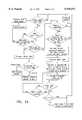
- FIGS. 4A and 4Bare flowcharts illustrating the operation of a communications module in accordance with the present invention.
- the CEBus protocoldoes not provide for repeaters.
- the present inventionwas designed to provide such repeater capability in a configurable communications module while using existing CEBus protocol structures and without violating CEBus protocol rules.
- the present inventionimproves end-to-end communications between two devices by effectively providing a signal boost at a point closer to the destination device.
- Typical CEBus messagesconsist of one or more packets.
- the repeater(“the repeater” refers to the RCM configured to act as a repeater) stores and immediately forwards each packet it is to repeat.
- a packet transmitted by a CEBus devicemay now be repeated by one or more repeaters before it reaches the destination device.
- the inventive communications modulemay also be configured to function as an interface between the CEBus network and a host application, and as a standalone device.
- a communications network in accordance with the present inventioncomprises a source device 10, in this example comprising a host application (HA) controlling a repeater communications module (RCM); a plurality of RCMs 12a and 12b; and a destination device 14, which in this example is a standalone RCM. All of the RCMs transmit or receive message packets to/from a CEBus communications medium. As shown in FIG. 2, the RCMs may be integrated or coupled to electricity meters in the form of combined meter/RCMs 12a' and 12b' associated with residences 16a and 16b, respectively. The example discussed below refers to a source device 10', or D1, in residence 16a and a destination device 14', or D2, in residence 16b.
- HAhost application
- RCMrepeater communications module
- FIG. 3is a block diagram of one presently preferred embodiment of an RCM 12.
- the presently preferred embodiment of the RCM 12comprises an electricity meter that includes a meter application 12-1; interface control lines 12-2; and a universal asynchronous receiver-transmitter (UART) 12-3.
- the RCM 12includes a communications module coupled to the meter.
- the communications modulecomprises a UART 12-4; interface control lines 12-5; a clock 12-6; reset circuitry 12-7; a microprocessor and its associated RAM and ROM 12-8; a CEBus transmitter 12-9; a CEBus receiver 12-10; and powerline coupling circuitry 12-11.
- the repeater functionalityis implemented entirely in firmware of an RCM 12.
- the firmwaremay be completely contained within the microprocessor 12-8, and the meter application 12-1 does not need to be aware of the repeating mechanism.
- An RCMcan either be a standalone device or an interface device.
- a standalone RCMnormally contains additional intelligence to perform a desired application task.
- One example of this type of RCMis an appliance relay which receives CEBus messages that turn on or turn off the appliance.
- a standalone RCMdoes not necessarily need to perform an application task. Its sole purpose can be to function as a repeater.
- An advantage of using RCMs that perform application tasks in addition to functioning as a repeateris the reduced number of total devices that must be installed for successful communications.
- An RCM which is an interface deviceis controlled by a host application.
- the host applicationcontains the intelligence required to perform an application task.
- the RCMreceives messages from the host application, converts the messages to the proper protocol and transmits the messages onto the communications medium. Messages received from the communications medium are converted by the RCM into an application protocol and passed to the host application.
- An example of thisis a CEBus RCM attached to a non-CEBus appliance.
- the RCMacts as a pass-through device, or interface, between the appliance and CEBus, converting between the appliance's native protocol and the CEBus protocol.
- the meter application with connected CM shown in FIG. 3is an example of an RCM controlled by a host application.
- Either type of RCMcan be configured to communicate using repeaters or to communicate directly to a destination device. Either type of RCM can also be configured to be a repeater. If the RCM is controlled by a host application, it will continue to function as the pass-through module for the application device. If an RCM is a standalone device, it can be configured to be a repeater without affecting performance of the RCM's application task. In one CEBus implementation, the RCM in the electricity meter is configured to be a repeater and all other RCMs in a residence are configured not to be repeaters. All RCMs are configured to communicate using repeaters.
- the combined RCM/electricity meter configurationwas chosen because the electricity meter is a 240 V device and its RCM communicates on the power line across both of the 240 V supply lines (L1-L2). 120 V devices communicate between line and neutral (L1-N or L2-N). Field installations have indicated that some residences experience problems communicating between 120 V devices which are powered from different lines (L1 or L2). For example, unreliable communications are more likely to occur when the source device is using L1-N and the destination device is using L2-N.
- the RCM in the electricity meterwas chosen also because it is electrically the entrance point into a residence. When communications are required between two different residences, the respective RCMs in the electricity meters at both residences pass messages into and out of their residence. This is illustrated in FIG. 2, which shows that a message from residence 16a device D1 to residence 16b device D2 is routed through the RCM repeaters 12a', 12b' located in the electricity meters.
- the route of a packetis determined by a Repeater Role Identifier (RRI).
- the RRIis contained in each packet of a message, and specifies which repeater is required to respond to the packet.
- the RRIis contained in the Source Device Address field.
- the CEBus protocolcontains the following 16-bit address fields: Destination Device Address, Destination House Code, Source Device Address, and Source Device House Code. Bits 12, 13, and 14 in the Source Device Address field are used to specify the repeater role.
- the 16-bit CEBus Source Device Address fieldis shown in Table 1.
- a 3-bit RRI fieldwas chosen in this example to satisfy the requirements for successful CEBus communications.
- the RRI fieldmay be larger or smaller based on the specific requirements.
- Each RCM configured as a repeatercontains a repeater role table (RRT). This table defines how the RCM is to respond to a packet which contains a non-zero RRI.
- RRTrepeater role table
- each entry in the RRTincludes the Destination Device Address, Destination House Code, Source Device Address, Source House Code, a receive RRI, or RRRI, and a transmit RRI, or TRRI.
- the repeaterWhen a repeater receives a packet containing addresses and an RRI which match an entry in the table, the repeater transmits a CEBus IACK to acknowledge that the packet has been received and will be forwarded, inserts the TRRI into the packet in place of the RRRI, and re-transmits the packet.
- a source deviceis responsible for inserting the correct RRI into the CEBus packet.
- Each RCM which invokes repeaterscontains a transmit role table (TRT) that defines which RRI is to be used for the packet to be transmitted.
- TRTtransmit role table
- each entry in this tableconsists of the Destination Device Address, Destination House Code, and a TRRI.
- the configurable nature of the RCMprovides the highest degree of flexibility, allowing for systems to be installed with or without the use of repeaters.
- RCMshave a special priority level when retransmitting a CEBus powerline packet.
- CEBususes a priority scheme that specifies the minimum channel quiet time that must elapse before a device is allowed to transmit.
- the minimum CEBus quiet timeis specified to be 10 Unit Symbol Times (USTs).
- USTsUnit Symbol Times
- the repeaterhas the capability to retry each packet if it does not successfully reach the next RCM in the communications chain.
- the next RCMmay be another repeater or it may be a destination device.
- successful packet transferis indicated by the receipt of an Immediate Acknowledge (IACK). If a repeated packet does not receive a CEBus IACK, the repeater will immediately retry the packet one time. If an IACK is not received for the second attempt, the repeater will wait one second and then retry transmission of the packet. This retry is similar to the first attempt in that there is one attempt and one immediate retry if an IACK has not been received.
- the number of retriesis a configurable parameter in the RCM, and can be between, e.g., 0 and 15.
- repeatercounts the device pairs it is currently supporting. When the repeater's limit is reached, a busy filter is invoked. In the preferred embodiment, this count is set to one device pair. When a busy filter is set, the addresses of the device pairs that are allowed to communicate through the repeater are known as the exception addresses. If a packet is received and both the source and destination addresses do not match an exception address pair, the repeater will issue an immediate response to the source device indicating that the repeater is busy and the source device should retry the message at a later time.
- This messageis known as a Busy INACK.
- the Busy INACKspecifies to the transmitting device the number of minutes or seconds for which the repeater will remain in a busy state. If the busy filter time is greater than one minute, the repeater will specify the time in minutes. If the busy filter time is less than one minute, the repeater will specify the time in seconds. While the busy filter is set, if the RCM is controlled by a host application, the RCM will also prevent the host application from communicating through the RCM onto the communications medium. If a packet received from the host application requires transmission, the RCM response will indicate to the application that the packet cannot be transmitted at this time. If the RCM receives a packet destined to this RCMs application and the repeat busy filter is set, the RCM will respond with a Busy INACK.
- This INACKis similar to a Busy INACK in that it tells the source device to retry the message later. However, the Failure INACK is only intended to slow down the source device. For the CEBus implementation, source devices or repeaters that receive a Failure INACK will retry the packet 1-2 seconds later.
- a source deviceWhen a source device sends a message to a destination device, it typically waits for a response message from the destination device to indicate that the message transfer was successful. If the destination device is not present or is not responding, the source device will typically time out waiting for a response and retry transmission of the message several times. If the message to be sent is a long message consisting of many packets, a substantial amount of time may be spent transferring all of the packets even though there is no response from the destination device. While each packet of the message is being sent, and normally until the busy filter set by the repeater times out, all repeaters in the message sequence remain busy to only the source and destination devices and will issue a busy response to any other device which attempts to communicate through the repeater. For example, referring to FIG.
- both the repeater in residence 16a and the repeater in residence 16bwill be set busy, dedicated solely to the transfer between D1 and D2. If at this time device D3 attempts to communicate through the repeater, the repeater will issue a Busy response to D3, preventing D3's communications session.
- the Open Pipe procedureis a short, one packet message used to establish an end-to-end link between the source and destination devices prior to transmission of a multi-packet message. If a response from the destination device is not received when the source device transmits the Open Pipe procedure, transmission of the multi-packet message is not attempted.
- the time required to retry the one packet Open Pipe procedureis significantly less than the time required to retry long messages with multiple packets, and the time for which the repeaters are unnecessarily held in a busy state is drastically reduced.
- an RCMwhen an RCM receives an Open Pipe procedure to which it is to respond, it sends an IACK to the device that sent the packet, and then repeats the packet.
- the repeateralso sets a busy filter as described above.
- bit 11 of the CEBus Source Device Address fieldis used as the Open Pipe bit. This bit is set by the RCM of the source device. If the bit in the packet is set, it tells the RCM that there are more packets to follow, and the RCM maintains the busy filter by resetting the busy time. If the Open Pipe bit in a packet to be repeated is clear, the RCM will forward the packet as normal and then clear the busy filter so that the next source/destination device pair may have access to the repeater.
- RCMs involved in the message transfer as either the source or destination devicewill set the Open Pipe bit equal to 1 in all packets except the last packet of a response message.
- the last packet of a responseindicates the end of a normal message sequence, and the Open Pipe bit is cleared to indicate that the communications session between the two devices has been completed, and any busy filters which are set may be cleared.
- the modulefirst determines whether a CEBus packet has been received. Once such a packet has been received, the module determines whether its busy filter is set. If so, the module then determines whether the addresses in the packet match the exception addresses. If the busy filter is set and the exception addresses do not match, the packet is discarded and a busy INACK is transmitted. On the other hand, if the exception addresses are matched or if the busy filter is not set, the module determines whether there is an RRI field in the received packet. If the RRI field equals zero, the module transmits a CEBus IACK and then either acts on the message packet (if in stand-alone mode) or transmits a local packet to a host application (if in interface mode).
- the moduledetermines whether it is configured as a repeater. If not, the packet is discarded. If it is configured as a repeater, the module determines whether there is an entry in the RRT with a matching source address, destination address and receive RRI. The packet is discarded if such an entry is not found. If such an entry is found, however, the module sets its busy filter and exception addresses for communication between source and destination devices, transmits a CEBus IACK, uses the transmit RRI in the matching RRT entry to modify the source device address field, and sets the repeat retry count to zero. The module then transmits, or repeats, the CEBus packet.
- the moduledetermines whether a CEBus IACK has been received. If not, and if the retry repeat count is less than "N", where N is a configurable parameter in the RCM, the module again transmits or repeats the CEBus packet. If, on the other hand, a CEBus IACK has been received or if the retry count is not less than N, the module determines whether its Open Pipe bit is set to 1. If not, the busy filter and exception addresses are cleared and the process loops back to the beginning. The module then determines whether another CEBus packet has been received. Similarly, if the Open Pipe bit is set, the module loops back to the beginning of the process.
- FIG. 4Billustrates the operation of the module in initiating, or transmitting, CEBus packets.
- the processbegins with the module determining whether it is in a stand-alone or interface mode. If in a stand-alone mode, the process proceeds to the left in FIG. 4B and the module determines whether a message packet is ready to be transmitted. If a packet is ready for transmission, the process proceeds down the center branch of the flowchart. On the other hand, if the module is in the interface mode, the process proceeds to the right in the flowchart and the module determines whether a message packet has been received from the host application. If so, the module modifies the packet to place it in a correct CEBus format, and the process proceeds down the center branch of the flowchart.
- the moduledetermines whether it has been configured to use the transmit role table, or TRT. If so, it uses the destination address to find an entry in the TRT, and then modifies the source device address field using the RRI for the TRT entry. After the latter two steps are performed, or if the module is not configured to use the TRT, the module sets the retry count to zero, transmits the CEBus packet, and then determines whether a CEBus IACK has been received. If a CEBus IACK has been received, the process loops back to the beginning.
- the moduledetermines whether the retry count is greater then zero; if so, the process loops back to the beginning and, if not, the module sets the retry count to 1 and loops back to the step wherein the CEBus packet is transmitted.
- the following exampleillustrates the action taken by repeaters during a message transfer between two devices.
- the devices shown in FIG. 2are used for this example.
- Each deviceis identified by two addresses, as follows:
- Device D1has a 30-packet message which is to be sent to device D2.
- the RCM in device D1is configured to transmit packets with an RRI.
- the RCMreceives the message, it first looks in its transmit role table to determine which RRI is to be inserted in each packet of the message.
- the three devicescontain the following TRTs:
- the RCM in device D1finds that the RRI for the message is %010.
- the RCMinserts this RRI into the Source Device Address field as follows:
- the RCMPrior to sending the 30 packet message, the RCM first sends the Open Pipe procedure to device D2. Notice that the Open Pipe bit in the Source Device Address field is set to ⁇ 1 ⁇ . This indicates to all repeaters involved in the message transfer that there are more packets to follow, and the repeaters in the chain are being asked to stay dedicated to the session between D1 and D2.
- the two RCMs(contained in the electricity meters at residences 16a and 16b) contain the following repeater role tables:
- the Open Pipe procedure packet transmit by device D1is received by both repeaters.
- the residence 16b repeaterlooks in its repeater role table and finds a match for the addresses but the receive RRI, or RRRI, is not a match, and so it ignores the message.
- the residence 16a repeaterfinds a complete match (entry #2), and so it sets a busy filter to allow only packets from devices D1 and D2 to be repeated.
- the repeaterthen takes the transmit RRI (TRRI) field formed with entry #2 (%001), inserts it into the received packet, and retransmits the packet.
- TRRItransmit RRI
- the Source Device Address field of the transmitted packetis:
- device D2When device D2 receives the Open Pipe procedure it sends a response message back through the repeaters to device D1. The receipt of this message by device D1 indicates that the channel is dedicated, and the 30 packet message may be sent. Each packet of the message follows the same steps outlined above for the Open Pipe packet. When device D2 receives the last packet, it sends a one packet response message to device D1 to indicate that the message was successfully received.
- the Source Device Address field in the response message sent by device D2is:
Landscapes
- Engineering & Computer Science (AREA)
- Computer Networks & Wireless Communication (AREA)
- Signal Processing (AREA)
- Small-Scale Networks (AREA)
- Data Exchanges In Wide-Area Networks (AREA)
Abstract
Description
TABLE 1 ______________________________________ CEBus Source Device Address field Bit 15 Bits 12-14 Bit 11 Bits 0-10 ______________________________________ unused RRI OP Bit Actual CEBus Source Device Address ______________________________________
______________________________________ Device Device House Code Address ______________________________________ D1 $000A $0001 D2 $000B $0002 D3 $000A $0003 ______________________________________
______________________________________ Device D1 Transmit Role Table Destination House Destination Device Entry Code Address Transmit RRI ______________________________________ 1 $000A $0003 %001 2 $000B $0002 %010 ______________________________________
______________________________________ Device D2 Transmit Role Table Destination House Destination Device Entry Code Address Transmit RRI ______________________________________ 1 $000A $0001 %010 2 $000A $0003 %010 ______________________________________
______________________________________ Device D3 Transmit Role Table Destination House Destination Device Entry Code Address Transmit RRI ______________________________________ 1 $000A $0001 %001 2 $000B $0002 %010 ______________________________________
______________________________________ unused RRI OP Bit Actual CEBus Source Device Address ______________________________________ 0 010 1 00000000001 ______________________________________
______________________________________ Residence A Repeater Role Table Source Source Dest. Dest. House Device House Device Receive Trans. Entry Code Address Code Address RRI RRI ______________________________________ 1 $000A $0001 $000A $0003 %001 %000 2 $000A $0001 $000B $0002 %010 %001 3 $000A $0003 $000A $0001 %001 %000 4 $000A $0003 $000B $0002 %010 %001 5 $000B $0002 $000A $0001 %001 %000 6 $000B $0002 $000A $0003 %001 %000 ______________________________________
______________________________________ Residence B Repeater Role Table Source Source Dest. Dest. House Device House Device Receive Trans. Entry Code Address Code Address RRI RRI ______________________________________ 1 $000A $0001 $000B $0002 %001 %000 2 $000A $0003 $000B $0002 %001 %000 3 $000B $0002 $000A $0001 %010 %001 4 $000B $0002 $000A $0003 %010 %001 ______________________________________
______________________________________ unused RRI OP Bit Actual CEBus Source Device Address ______________________________________ 0 001 1 00000000001 ______________________________________
______________________________________ unused RRI OP Bit Actual CEBus Source Device Address ______________________________________ 0 010 0 00000000002 ______________________________________
Claims (26)
Priority Applications (4)
| Application Number | Priority Date | Filing Date | Title |
|---|---|---|---|
| US08/828,539US5978371A (en) | 1997-03-31 | 1997-03-31 | Communications module base repeater |
| AU65863/98AAU6586398A (en) | 1997-03-31 | 1998-03-26 | Communications module based repeater |
| CA002285334ACA2285334C (en) | 1997-03-31 | 1998-03-26 | Communications module based repeater |
| PCT/US1998/005949WO1998048536A2 (en) | 1997-03-31 | 1998-03-26 | Communications module based repeater |
Applications Claiming Priority (1)
| Application Number | Priority Date | Filing Date | Title |
|---|---|---|---|
| US08/828,539US5978371A (en) | 1997-03-31 | 1997-03-31 | Communications module base repeater |
Publications (1)
| Publication Number | Publication Date |
|---|---|
| US5978371Atrue US5978371A (en) | 1999-11-02 |
Family
ID=25252103
Family Applications (1)
| Application Number | Title | Priority Date | Filing Date |
|---|---|---|---|
| US08/828,539Expired - LifetimeUS5978371A (en) | 1997-03-31 | 1997-03-31 | Communications module base repeater |
Country Status (4)
| Country | Link |
|---|---|
| US (1) | US5978371A (en) |
| AU (1) | AU6586398A (en) |
| CA (1) | CA2285334C (en) |
| WO (1) | WO1998048536A2 (en) |
Cited By (113)
| Publication number | Priority date | Publication date | Assignee | Title |
|---|---|---|---|---|
| US20020012323A1 (en)* | 1999-03-18 | 2002-01-31 | Petite Thomas D. | Systems and methods for enabling a mobile user to notify an automated monitoring system of an emergency situation |
| WO2002015413A3 (en)* | 2000-08-14 | 2002-08-01 | Main Net Comm | Power line communication system |
| US20030071719A1 (en)* | 2001-10-02 | 2003-04-17 | Crenshaw Ralph E. | Method and apparatus for attaching power line communications to customer premises |
| US20040151237A1 (en)* | 2000-05-31 | 2004-08-05 | Bitrage, Inc. | Satellite communications system |
| US20040174851A1 (en)* | 2001-07-17 | 2004-09-09 | Yeshayahu Zalitzky | Dual purpose power line modem |
| US20040227623A1 (en)* | 2003-05-07 | 2004-11-18 | Telkonet, Inc. | Network topology and packet routing method using low voltage power wiring |
| US6823001B1 (en) | 2000-05-31 | 2004-11-23 | Bitrage, Inc. | Dual stage communication processor |
| US20040233928A1 (en)* | 2003-05-07 | 2004-11-25 | Telkonet, Inc. | Network topology and packet routing method using low voltage power wiring |
| US6836737B2 (en) | 2000-08-09 | 2004-12-28 | Statsignal Systems, Inc. | Systems and methods for providing remote monitoring of consumption for a utility meter |
| US20050007241A1 (en)* | 2000-01-20 | 2005-01-13 | Kline Paul A. | Method of isolating data in a power line communications network |
| US20050008028A1 (en)* | 2001-07-23 | 2005-01-13 | Ofir Efrati | Dynamic power line access connection |
| US20050017847A1 (en)* | 2003-07-24 | 2005-01-27 | Bonicatto Damian G. | Power line communication system having time server |
| US20050020232A1 (en)* | 2003-07-24 | 2005-01-27 | Bonicatto Damian G. | Data communication over power lines |
| US20050046550A1 (en)* | 2001-10-02 | 2005-03-03 | Crenshaw Ralph E. | Method and apparatus for attaching power line communications to customer premises |
| US20050055586A1 (en)* | 2003-07-24 | 2005-03-10 | Hunt Technologies, Inc. | Endpoint event processing system |
| US20050083925A1 (en)* | 2003-07-24 | 2005-04-21 | Bonicatto Damian G. | Locating endpoints in a power line communication system |
| US6891838B1 (en) | 1998-06-22 | 2005-05-10 | Statsignal Ipc, Llc | System and method for monitoring and controlling residential devices |
| US6933835B2 (en) | 2001-02-14 | 2005-08-23 | Current Technologies, Llc | Data communication over a power line |
| US6950567B2 (en) | 2001-02-14 | 2005-09-27 | Current Technologies, Llc | Method and apparatus for providing inductive coupling and decoupling of high-frequency, high-bandwidth data signals directly on and off of a high voltage power line |
| US6958680B2 (en) | 2000-04-14 | 2005-10-25 | Current Technologies, Llc | Power line communication system and method of using the same |
| US6965303B2 (en) | 2002-12-10 | 2005-11-15 | Current Technologies, Llc | Power line communication system and method |
| US6965302B2 (en) | 2000-04-14 | 2005-11-15 | Current Technologies, Llc | Power line communication system and method of using the same |
| US20050267788A1 (en)* | 2004-05-13 | 2005-12-01 | International Business Machines Corporation | Workflow decision management with derived scenarios and workflow tolerances |
| US6977578B2 (en) | 2000-01-20 | 2005-12-20 | Current Technologies, Llc | Method of isolating data in a power line communications network |
| US6980091B2 (en) | 2002-12-10 | 2005-12-27 | Current Technologies, Llc | Power line communication system and method of operating the same |
| US6980089B1 (en) | 2000-08-09 | 2005-12-27 | Current Technologies, Llc | Non-intrusive coupling to shielded power cable |
| US6980090B2 (en) | 2002-12-10 | 2005-12-27 | Current Technologies, Llc | Device and method for coupling with electrical distribution network infrastructure to provide communications |
| US6982611B2 (en) | 2002-06-24 | 2006-01-03 | Current Technologies, Llc | Power line coupling device and method of using the same |
| US6998962B2 (en) | 2000-04-14 | 2006-02-14 | Current Technologies, Llc | Power line communication apparatus and method of using the same |
| US20060038700A1 (en)* | 2004-08-23 | 2006-02-23 | Scott Cumeralto | Sleeve repeater for forwarding meter data |
| US7046124B2 (en) | 2003-01-21 | 2006-05-16 | Current Technologies, Llc | Power line coupling device and method of using the same |
| US7053767B2 (en) | 1998-06-22 | 2006-05-30 | Statsignal Systems, Inc. | System and method for monitoring and controlling remote devices |
| US7053756B2 (en) | 2001-12-21 | 2006-05-30 | Current Technologies, Llc | Facilitating communication of data signals on electric power systems |
| US20060114925A1 (en)* | 2004-12-01 | 2006-06-01 | At&T Corp. | Interference control in a broadband powerline communication system |
| US20060126647A1 (en)* | 2004-12-15 | 2006-06-15 | Hicks John A Iii | Network interface device |
| US7064654B2 (en) | 2002-12-10 | 2006-06-20 | Current Technologies, Llc | Power line communication system and method of operating the same |
| US7076378B1 (en) | 2002-11-13 | 2006-07-11 | Current Technologies, Llc | Device and method for providing power line characteristics and diagnostics |
| US7075414B2 (en) | 2003-05-13 | 2006-07-11 | Current Technologies, Llc | Device and method for communicating data signals through multiple power line conductors |
| US7079810B2 (en) | 1997-02-14 | 2006-07-18 | Statsignal Ipc, Llc | System and method for communicating with a remote communication unit via the public switched telephone network (PSTN) |
| US20060192672A1 (en)* | 2004-10-26 | 2006-08-31 | Gidge Brett D | Power line communications device and method |
| US20060193313A1 (en)* | 2005-02-25 | 2006-08-31 | Telkonet, Inc. | Local area network above telephony infrastructure |
| US20060193336A1 (en)* | 2005-02-25 | 2006-08-31 | Telkonet, Inc. | Local area network above cable television methods and devices |
| US20060193310A1 (en)* | 2005-02-25 | 2006-08-31 | Telkonet, Inc. | Local area network above telephony methods and devices |
| US7103511B2 (en) | 1998-10-14 | 2006-09-05 | Statsignal Ipc, Llc | Wireless communication networks for providing remote monitoring of devices |
| US7102478B2 (en) | 2002-06-21 | 2006-09-05 | Current Technologies, Llc | Power line coupling device and method of using the same |
| US20060200255A1 (en)* | 2005-03-04 | 2006-09-07 | Electrolux Home Products Corporation N.V. | Domestic appliance assembly with integrated functioning |
| US7113134B1 (en) | 2004-03-12 | 2006-09-26 | Current Technologies, Llc | Transformer antenna device and method of using the same |
| US7132819B1 (en) | 2002-11-12 | 2006-11-07 | Current Technologies, Llc | Floating power supply and method of using the same |
| US7137550B1 (en) | 1997-02-14 | 2006-11-21 | Statsignal Ipc, Llc | Transmitter for accessing automated financial transaction machines |
| US7149242B1 (en) | 2000-05-31 | 2006-12-12 | Bitrage, Inc. | Communications system for improving transmission rates and transmission distances of data signals across communications links |
| US20070001821A1 (en)* | 2005-06-21 | 2007-01-04 | Berkman William H | Method and device for amplification of data signals over power lines |
| US7187276B2 (en) | 2001-02-14 | 2007-03-06 | Current Technologies, Llc | Power line communication system and method of using the same |
| US7199699B1 (en) | 2002-02-19 | 2007-04-03 | Current Technologies, Llc | Facilitating communication with power line communication devices |
| US20070076666A1 (en)* | 2005-10-03 | 2007-04-05 | Riveiro Juan C | Multi-Wideband Communications over Power Lines |
| US20070075843A1 (en)* | 2005-10-03 | 2007-04-05 | Riveiro Juan C | Multi-Wideband Communications over Power Lines |
| US20070100884A1 (en)* | 2005-11-01 | 2007-05-03 | Brown William A | Workflow decision management with message logging |
| US20070101007A1 (en)* | 2005-11-01 | 2007-05-03 | Brown William A | Workflow decision management with intermediate message validation |
| US20070098013A1 (en)* | 2005-11-01 | 2007-05-03 | Brown William A | Intermediate message invalidation |
| US20070116013A1 (en)* | 2005-11-01 | 2007-05-24 | Brown William A | Workflow decision management with workflow modification in dependence upon user reactions |
| US7224272B2 (en) | 2002-12-10 | 2007-05-29 | Current Technologies, Llc | Power line repeater system and method |
| US20070189182A1 (en)* | 2006-02-14 | 2007-08-16 | Berkman William H | Method for establishing power line communication link |
| US7259657B2 (en) | 2005-06-21 | 2007-08-21 | Current Technologies, Llc | Multi-subnet power line communications system and method |
| US7265664B2 (en) | 2005-04-04 | 2007-09-04 | Current Technologies, Llc | Power line communications system and method |
| US20070229231A1 (en)* | 2005-10-03 | 2007-10-04 | Hurwitz Jonathan E D | Multi-Wideband Communications over Multiple Mediums within a Network |
| US7295128B2 (en) | 1998-06-22 | 2007-11-13 | Sipco, Llc | Smoke detection methods, devices, and systems |
| US7308103B2 (en) | 2003-05-08 | 2007-12-11 | Current Technologies, Llc | Power line communication device and method of using the same |
| US20080008081A1 (en)* | 2006-07-06 | 2008-01-10 | Gigle Semiconductor Inc. | Adaptative multi-carrier code division multiple access |
| US20080012724A1 (en)* | 2006-01-30 | 2008-01-17 | Corcoran Kevin F | Power line communications module and method |
| US7346463B2 (en) | 2001-08-09 | 2008-03-18 | Hunt Technologies, Llc | System for controlling electrically-powered devices in an electrical network |
| US20080117896A1 (en)* | 2006-11-21 | 2008-05-22 | Veronica Romero | Network repeater |
| US20080130640A1 (en)* | 2005-10-03 | 2008-06-05 | Jonathan Ephraim David Hurwitz | Multi-Wideband Communications over Multiple Mediums |
| US20080159358A1 (en)* | 2007-01-02 | 2008-07-03 | David Ruiz | Unknown Destination Traffic Repetition |
| US7397907B2 (en) | 1997-02-14 | 2008-07-08 | Sipco, Llc | Multi-function general purpose transceiver |
| US20080174847A1 (en)* | 2007-01-24 | 2008-07-24 | Adelphi University | Interferometric method for improving the resolution of a lithographic system |
| US20080178193A1 (en)* | 2005-01-10 | 2008-07-24 | International Business Machines Corporation | Workflow Decision Management Including Identifying User Reaction To Workflows |
| US20080181186A1 (en)* | 2007-01-31 | 2008-07-31 | Broadcom Corporation, A California Corporation | Intra-device RF bus and control thereof |
| USRE40492E1 (en) | 2000-02-10 | 2008-09-09 | Telkonet Communications, Inc. | Power line telephony exchange |
| US7424527B2 (en) | 2001-10-30 | 2008-09-09 | Sipco, Llc | System and method for transmitting pollution information over an integrated wireless network |
| US20080235706A1 (en)* | 2005-01-10 | 2008-09-25 | International Business Machines Corporation | Workflow Decision Management With Heuristics |
| US7460467B1 (en) | 2003-07-23 | 2008-12-02 | Current Technologies, Llc | Voice-over-IP network test device and method |
| US7480501B2 (en) | 2001-10-24 | 2009-01-20 | Statsignal Ipc, Llc | System and method for transmitting an emergency message over an integrated wireless network |
| US7640351B2 (en) | 2005-11-04 | 2009-12-29 | Intermatic Incorporated | Application updating in a home automation data transfer system |
| US7650425B2 (en) | 1999-03-18 | 2010-01-19 | Sipco, Llc | System and method for controlling communication between a host computer and communication devices associated with remote devices in an automated monitoring system |
| US7694005B2 (en) | 2005-11-04 | 2010-04-06 | Intermatic Incorporated | Remote device management in a home automation data transfer system |
| US7697492B2 (en) | 1998-06-22 | 2010-04-13 | Sipco, Llc | Systems and methods for monitoring and controlling remote devices |
| US7698448B2 (en) | 2005-11-04 | 2010-04-13 | Intermatic Incorporated | Proxy commands and devices for a home automation data transfer system |
| US20100090765A1 (en)* | 2008-10-13 | 2010-04-15 | Hurwitz Jonathan Ephraim David | Programmable Gain Amplifier |
| US20100111112A1 (en)* | 2008-10-31 | 2010-05-06 | Square D Company | Automated synchronization of data between electrical grids |
| US20100117734A1 (en)* | 2008-10-13 | 2010-05-13 | Jonathan Ephraim David Hurwitz | Programmable Gain Amplifier and Transconductance Compensation System |
| US20100130142A1 (en)* | 2008-11-25 | 2010-05-27 | Square D Company | Wireless transceiver within an electrical receptacle system |
| US7756086B2 (en) | 2004-03-03 | 2010-07-13 | Sipco, Llc | Method for communicating in dual-modes |
| US7764943B2 (en) | 2006-03-27 | 2010-07-27 | Current Technologies, Llc | Overhead and underground power line communication system and method using a bypass |
| US7796025B2 (en) | 2006-03-27 | 2010-09-14 | Current Technologies, Llc | Power line communication device and method |
| US20100236296A1 (en)* | 2007-08-16 | 2010-09-23 | Choi Kyung Ah | Total laundry treating system |
| US20100289629A1 (en)* | 2008-10-28 | 2010-11-18 | Cooper Technologies Company | Load Control Device with Two-Way Communication Capabilities |
| US7856032B2 (en) | 2005-04-04 | 2010-12-21 | Current Technologies, Llc | Multi-function modem device |
| US20110004324A1 (en)* | 2009-07-01 | 2011-01-06 | Square D Company | Automatic identification of multiple power grids using data synchronization |
| US7870232B2 (en) | 2005-11-04 | 2011-01-11 | Intermatic Incorporated | Messaging in a home automation data transfer system |
| US8000314B2 (en) | 1996-12-06 | 2011-08-16 | Ipco, Llc | Wireless network system and method for providing same |
| US8031650B2 (en) | 2004-03-03 | 2011-10-04 | Sipco, Llc | System and method for monitoring remote devices with a dual-mode wireless communication protocol |
| US8035507B2 (en) | 2008-10-28 | 2011-10-11 | Cooper Technologies Company | Method and apparatus for stimulating power line carrier injection with reactive oscillation |
| US20130046881A1 (en)* | 2011-08-19 | 2013-02-21 | Ecolink Intelligent Technology, Inc. | Method and Apparatus For Network Device Detection |
| US8410931B2 (en) | 1998-06-22 | 2013-04-02 | Sipco, Llc | Mobile inventory unit monitoring systems and methods |
| US8489063B2 (en) | 2001-10-24 | 2013-07-16 | Sipco, Llc | Systems and methods for providing emergency messages to a mobile device |
| US20140192705A1 (en)* | 2011-06-20 | 2014-07-10 | Telefonaktiebolaget L M Ericsson (Publ) | Selective Relaying in a Network Node |
| US8787246B2 (en) | 2009-02-03 | 2014-07-22 | Ipco, Llc | Systems and methods for facilitating wireless network communication, satellite-based wireless network systems, and aircraft-based wireless network systems, and related methods |
| TWI451708B (en)* | 2007-10-08 | 2014-09-01 | Adc Dsl Sys Inc | A regenerator unit |
| US8885814B2 (en) | 2006-07-25 | 2014-11-11 | Broadcom Europe Limited | Feedback impedance control for driving a signal |
| US9077208B2 (en) | 2011-12-30 | 2015-07-07 | Schneider Electric USA, Inc. | Method of detecting instability in islanded electrical systems |
| US9420515B2 (en) | 2011-10-18 | 2016-08-16 | Itron, Inc. | Endpoint repeater functionality selection |
| US9439126B2 (en) | 2005-01-25 | 2016-09-06 | Sipco, Llc | Wireless network protocol system and methods |
| US9594587B2 (en) | 2005-11-01 | 2017-03-14 | International Business Machines Corporation | Workflow decision management with workflow administration capacities |
| US12088423B2 (en)* | 2011-08-19 | 2024-09-10 | Ecolink Intelligent Technology, Inc. | Method and apparatus for network device registration |
Citations (104)
| Publication number | Priority date | Publication date | Assignee | Title |
|---|---|---|---|---|
| US3611201A (en)* | 1969-10-21 | 1971-10-05 | Bell Telephone Labor Inc | Carrier transversal equalizer |
| US3702460A (en)* | 1971-11-30 | 1972-11-07 | John B Blose | Communications system for electric power utility |
| US3911415A (en)* | 1973-12-18 | 1975-10-07 | Westinghouse Electric Corp | Distribution network power line carrier communication system |
| US3942168A (en)* | 1975-01-31 | 1976-03-02 | Westinghouse Electric Corporation | Distribution network power line communication system |
| US3962547A (en)* | 1975-05-27 | 1976-06-08 | Westinghouse Electric Corporation | Repeater coupler for power line communication systems |
| US3967264A (en)* | 1975-01-31 | 1976-06-29 | Westinghouse Electric Corporation | Distribution network power line communication system including addressable interrogation and response repeater |
| US3973087A (en)* | 1974-12-05 | 1976-08-03 | General Electric Company | Signal repeater for power line access data system |
| US3973240A (en)* | 1974-12-05 | 1976-08-03 | General Electric Company | Power line access data system |
| US4004110A (en)* | 1975-10-07 | 1977-01-18 | Westinghouse Electric Corporation | Power supply for power line carrier communication systems |
| US4008467A (en)* | 1975-09-16 | 1977-02-15 | Westinghouse Electric Corporation | Power line carrier communication system having efficient carrier signal coupling of distribution secondary lines |
| US4016429A (en)* | 1976-01-16 | 1977-04-05 | Westinghouse Electric Corporation | Power line carrier communication system for signaling customer locations through ground wire conductors |
| US4024528A (en)* | 1975-10-30 | 1977-05-17 | Boggs Luther M | Remote switching system |
| US4032911A (en)* | 1976-02-26 | 1977-06-28 | Westinghouse Electric Corporation | Signal repeater for power distribution line communication systems |
| US4130874A (en)* | 1977-06-13 | 1978-12-19 | Westinghouse Electric Corp. | Load management terminal having plural selectable address formats for a power line communication system |
| US4156866A (en)* | 1976-10-07 | 1979-05-29 | Systems Technology Corporation | Multiple remote terminal digital control system |
| US4210901A (en)* | 1977-04-25 | 1980-07-01 | Westinghouse Electric Corp. | Signal repeater for a distribution network communication system |
| US4250489A (en)* | 1978-10-31 | 1981-02-10 | Westinghouse Electric Corp. | Distribution network communication system having branch connected repeaters |
| US4270206A (en)* | 1980-02-25 | 1981-05-26 | General Electric Company | Transceiver for phase-shift modulated carrier signals |
| US4292546A (en)* | 1980-03-06 | 1981-09-29 | Clark Warren P | Apparatus for controlling power application |
| US4302750A (en)* | 1979-08-03 | 1981-11-24 | Compuguard Corporation | Distribution automation system |
| US4307464A (en)* | 1979-12-26 | 1981-12-22 | General Electric Company | Method and apparatus for synthesizing a modulated carrier to reduced interchannel interference in a digital communication system |
| US4348582A (en)* | 1978-03-14 | 1982-09-07 | Texas Instruments Incorporated | Communication via an electricity supply main |
| US4357598A (en)* | 1981-04-09 | 1982-11-02 | Westinghouse Electric Corp. | Three-phase power distribution network communication system |
| US4427968A (en)* | 1981-04-09 | 1984-01-24 | Westinghouse Electric Corp. | Distribution network communication system with flexible message routes |
| US4467314A (en)* | 1982-03-29 | 1984-08-21 | Westinghouse Electric Corp. | Electric utility communication system with field installation terminal and load management terminal with remotely assignable unique address |
| US4471399A (en)* | 1982-03-11 | 1984-09-11 | Westinghouse Electric Corp. | Power-line baseband communication system |
| US4475209A (en)* | 1982-04-23 | 1984-10-02 | Westinghouse Electric Corp. | Regenerator for an intrabundle power-line communication system |
| US4500837A (en)* | 1981-01-15 | 1985-02-19 | Westinghouse Electric Corp. | Detection of DC content in an AC waveform |
| US4527247A (en)* | 1981-07-31 | 1985-07-02 | Ibg International, Inc. | Environmental control system |
| US4551780A (en)* | 1979-01-10 | 1985-11-05 | Bbc Brown, Boveri & Company, Limited | Apparatus for reducing subsynchronous frequencies in a power supply |
| US4556865A (en)* | 1982-08-09 | 1985-12-03 | Matsushita Electric Works, Ltd. | Data transmission system utilizing power line |
| US4599598A (en)* | 1981-09-14 | 1986-07-08 | Matsushita Electric Works, Ltd. | Data transmission system utilizing power line |
| US4628443A (en)* | 1984-11-16 | 1986-12-09 | General Electric Company | Test initiating apparatus for appliances having self-diagnostic testing capability |
| US4628503A (en)* | 1983-02-09 | 1986-12-09 | Brown, Boveri & Cie Ag | Method and device for performing a bus request and collective acknowledgement in a process bus system |
| US4638298A (en)* | 1985-07-16 | 1987-01-20 | Telautograph Corporation | Communication system having message repeating terminals |
| US4645956A (en)* | 1984-09-11 | 1987-02-24 | Westinghouse Electric Corp. | Current limiter for power line communication amplifier |
| US4668934A (en)* | 1984-10-22 | 1987-05-26 | Westinghouse Electric Corp. | Receiver apparatus for three-phase power line carrier communications |
| US4675668A (en)* | 1982-12-30 | 1987-06-23 | Sharp Kabushiki Kaisha | Data transmission system over building wiring |
| US4686382A (en)* | 1985-08-14 | 1987-08-11 | Westinghouse Electric Corp. | Switch bypass circuit for power line communication systems |
| US4692761A (en)* | 1985-06-21 | 1987-09-08 | Robinton Products, Inc. | Adaptive communication network and method |
| US4697166A (en)* | 1986-08-11 | 1987-09-29 | Nippon Colin Co., Ltd. | Method and apparatus for coupling transceiver to power line carrier system |
| US4703306A (en)* | 1986-09-26 | 1987-10-27 | The Maytag Company | Appliance system |
| US4746897A (en)* | 1984-01-30 | 1988-05-24 | Westinghouse Electric Corp. | Apparatus for transmitting and receiving a power line |
| US4749992A (en)* | 1986-07-03 | 1988-06-07 | Total Energy Management Consultants Corp. (Temco) | Utility monitoring and control system |
| US4756009A (en)* | 1985-07-15 | 1988-07-05 | Bbc Brown, Boveri & Company, Limited | Method for transmitting digital data |
| US4755792A (en)* | 1985-06-13 | 1988-07-05 | Black & Decker Inc. | Security control system |
| US4760375A (en)* | 1983-10-28 | 1988-07-26 | Josef Stecker | Data transmission cable |
| US4763104A (en)* | 1986-03-19 | 1988-08-09 | Mitsubishi Denki Kabushiki Kaisha | Gateway for use in load control system |
| US4766414A (en)* | 1986-06-17 | 1988-08-23 | Westinghouse Electric Corp. | Power line communication interference preventing circuit |
| US4774716A (en)* | 1986-01-22 | 1988-09-27 | Bbc Brown, Boveri & Company, Limited | Method for the transmission of digital data |
| US4800363A (en)* | 1986-01-15 | 1989-01-24 | Bbc Brown, Boveri & Company, Limited | Method for data transmission via an electric distribution system and transmission system for carrying out the method |
| US4809296A (en)* | 1986-02-27 | 1989-02-28 | Bbc Brown, Boveri Ltd. | Method for transmitting data via the lines of a power supply system |
| US4815106A (en)* | 1986-04-16 | 1989-03-21 | Adaptive Networks, Inc. | Power line communication apparatus |
| US4835517A (en)* | 1984-01-26 | 1989-05-30 | The University Of British Columbia | Modem for pseudo noise communication on A.C. lines |
| US4841281A (en)* | 1987-06-16 | 1989-06-20 | Westinghouse Electric Corp. | Apparatus for controlling a switching amplifier |
| US4847781A (en)* | 1986-09-23 | 1989-07-11 | Associated Data Consoltants | Energy management system |
| US4890089A (en)* | 1988-11-25 | 1989-12-26 | Westinghouse Electric Corp. | Distribution of line carrier communications |
| US4899129A (en)* | 1987-12-01 | 1990-02-06 | Smart House Limited Partnership | Automated appliance and energy distribution control system |
| US4899217A (en)* | 1987-12-01 | 1990-02-06 | Smart House Limited Partnership | Communication and energy control system for houses |
| US4914418A (en)* | 1989-01-03 | 1990-04-03 | Emerson Electric Co. | Outbound detector system and method |
| US4918690A (en)* | 1987-11-10 | 1990-04-17 | Echelon Systems Corp. | Network and intelligent cell for providing sensing, bidirectional communications and control |
| US4937569A (en)* | 1985-05-09 | 1990-06-26 | Emi Limited | Data communication system |
| US4962496A (en)* | 1988-10-20 | 1990-10-09 | Abb Power T & D Company Inc. | Transmission of data via power lines |
| US4969146A (en)* | 1987-11-10 | 1990-11-06 | Echelon Systems Corporation | Protocol for network having a plurality of intelligent cells |
| US4980665A (en)* | 1987-05-22 | 1990-12-25 | Recoton Corporation | Remote control repeater |
| US5034882A (en)* | 1987-11-10 | 1991-07-23 | Echelon Corporation | Multiprocessor intelligent cell for a network which provides sensing, bidirectional communications and control |
| US5049872A (en)* | 1987-09-14 | 1991-09-17 | Mitsubishi Denki Kabushiki Kaisha | Remote supervisory control system |
| US5065150A (en)* | 1988-07-29 | 1991-11-12 | Hochiki Corp. | Monitoring apparatus for disaster prevention |
| US5086385A (en)* | 1989-01-31 | 1992-02-04 | Custom Command Systems | Expandable home automation system |
| US5090024A (en)* | 1989-08-23 | 1992-02-18 | Intellon Corporation | Spread spectrum communications system for networks |
| US5097249A (en)* | 1989-05-16 | 1992-03-17 | Sony Corporation | Power status detecting apparatus |
| US5101191A (en)* | 1987-12-01 | 1992-03-31 | Smart House Limited Partnership | Electrical and communication system capable of providing uninterruptable power in a house |
| US5151838A (en)* | 1989-09-20 | 1992-09-29 | Dockery Gregory A | Video multiplying system |
| US5175677A (en)* | 1988-04-21 | 1992-12-29 | Mitsubishi Denki Kabushiki Kaisha | Load control system |
| US5185591A (en)* | 1991-07-12 | 1993-02-09 | Abb Power T&D Co., Inc. | Power distribution line communication system for and method of reducing effects of signal cancellation |
| US5198796A (en)* | 1991-06-27 | 1993-03-30 | Distribution Control Systems, Inc. | Outbound signal detector system and method |
| US5218354A (en)* | 1989-06-23 | 1993-06-08 | Motorola, Inc. | Communication system with improved resource assignment |
| US5218552A (en)* | 1990-07-30 | 1993-06-08 | Smart House, L.P. | Control apparatus for use in a dwelling |
| US5268666A (en)* | 1991-12-23 | 1993-12-07 | At&T Bell Laboratories | Appliance control system providing out-of-context usage |
| US5289158A (en)* | 1992-03-27 | 1994-02-22 | Neves James E | Range monitoring apparatus |
| US5385297A (en)* | 1991-10-01 | 1995-01-31 | American Standard Inc. | Personal comfort system |
| US5391932A (en)* | 1993-07-20 | 1995-02-21 | Echelon Corporation | Source power coupler |
| US5402419A (en)* | 1992-12-21 | 1995-03-28 | Sony Corporation | Transmitting method, receiving method, and communication method for bi-directional bus system, and bi-directional bus system |
| US5404127A (en)* | 1991-05-10 | 1995-04-04 | Echelon Corporation | Power line communication while avoiding determinable interference harmonics |
| US5424587A (en)* | 1992-09-08 | 1995-06-13 | Federowicz; John S. | Integrated electrical/communication system hardware |
| US5424710A (en)* | 1993-07-14 | 1995-06-13 | Echelon Corporation | Power coupler for coupling power from a transmission line to a node thereon |
| US5428351A (en)* | 1992-12-28 | 1995-06-27 | General Electric Company | Method and apparatus for sharing passwords |
| US5430663A (en)* | 1992-12-11 | 1995-07-04 | Vibrametrics, Inc. | Fault tolerant multipoint data collection system |
| US5434558A (en)* | 1991-07-05 | 1995-07-18 | Zeder; Abraham | Annunciator apparatus for monitoring electrical connections |
| US5442335A (en)* | 1992-11-13 | 1995-08-15 | I.D. Tek Inc. | Controller for controlling operation of at least one electrical load operating on an AC supply, and a method thereof |
| US5448229A (en)* | 1992-12-28 | 1995-09-05 | General Electric Company | Method and apparatus for communicating with a meter register |
| US5452291A (en)* | 1993-11-30 | 1995-09-19 | Panasonic Technologies, Inc. | Combination brouter and cluster controller |
| US5459459A (en)* | 1992-12-28 | 1995-10-17 | General Electric Company | Method and apparatus for transmitting data from an energy meter |
| US5471190A (en)* | 1989-07-20 | 1995-11-28 | Timothy D. Schoechle | Method and apparatus for resource allocation in a communication network system |
| US5475363A (en)* | 1993-03-16 | 1995-12-12 | Hochiki Corporation | Disaster prevention monitoring apparatus |
| US5495235A (en)* | 1992-09-30 | 1996-02-27 | At&T Corp. | Access control system with lockout |
| US5495239A (en)* | 1994-08-02 | 1996-02-27 | General Electric Company | Method and apparatus for communicating with a plurality of electrical metering devices and a system control center with a mobile node |
| US5537549A (en)* | 1993-04-28 | 1996-07-16 | Allen-Bradley Company, Inc. | Communication network with time coordinated station activity by time slot and periodic interval number |
| US5579523A (en)* | 1992-10-13 | 1996-11-26 | Sony Corporation | Method for controlled locking/unlocking of a system using a locking mode flag during an interrupt routine |
| US5598406A (en) | 1992-11-06 | 1997-01-28 | Hewlett-Packard Company | High speed data transfer over twisted pair cabling |
| US5699276A (en) | 1995-12-15 | 1997-12-16 | Roos; Charles E. | Utility meter providing an interface between a digital network and home electronics |
| US5736965A (en) | 1996-02-07 | 1998-04-07 | Lutron Electronics Co. Inc. | Compact radio frequency transmitting and receiving antenna and control device employing same |
| US5748104A (en) | 1996-07-11 | 1998-05-05 | Qualcomm Incorporated | Wireless remote telemetry system |
| US5839097A (en) | 1996-04-20 | 1998-11-17 | Robert Bosch Gmbh | Electrical home appliance |
- 1997
- 1997-03-31USUS08/828,539patent/US5978371A/ennot_activeExpired - Lifetime
- 1998
- 1998-03-26CACA002285334Apatent/CA2285334C/ennot_activeExpired - Lifetime
- 1998-03-26WOPCT/US1998/005949patent/WO1998048536A2/enactiveApplication Filing
- 1998-03-26AUAU65863/98Apatent/AU6586398A/ennot_activeAbandoned
Patent Citations (106)
| Publication number | Priority date | Publication date | Assignee | Title |
|---|---|---|---|---|
| US3611201A (en)* | 1969-10-21 | 1971-10-05 | Bell Telephone Labor Inc | Carrier transversal equalizer |
| US3702460A (en)* | 1971-11-30 | 1972-11-07 | John B Blose | Communications system for electric power utility |
| US3911415A (en)* | 1973-12-18 | 1975-10-07 | Westinghouse Electric Corp | Distribution network power line carrier communication system |
| US3973087A (en)* | 1974-12-05 | 1976-08-03 | General Electric Company | Signal repeater for power line access data system |
| US3973240A (en)* | 1974-12-05 | 1976-08-03 | General Electric Company | Power line access data system |
| US3942168A (en)* | 1975-01-31 | 1976-03-02 | Westinghouse Electric Corporation | Distribution network power line communication system |
| US3967264A (en)* | 1975-01-31 | 1976-06-29 | Westinghouse Electric Corporation | Distribution network power line communication system including addressable interrogation and response repeater |
| US3962547A (en)* | 1975-05-27 | 1976-06-08 | Westinghouse Electric Corporation | Repeater coupler for power line communication systems |
| US4008467A (en)* | 1975-09-16 | 1977-02-15 | Westinghouse Electric Corporation | Power line carrier communication system having efficient carrier signal coupling of distribution secondary lines |
| US4004110A (en)* | 1975-10-07 | 1977-01-18 | Westinghouse Electric Corporation | Power supply for power line carrier communication systems |
| US4024528A (en)* | 1975-10-30 | 1977-05-17 | Boggs Luther M | Remote switching system |
| US4016429A (en)* | 1976-01-16 | 1977-04-05 | Westinghouse Electric Corporation | Power line carrier communication system for signaling customer locations through ground wire conductors |
| US4032911A (en)* | 1976-02-26 | 1977-06-28 | Westinghouse Electric Corporation | Signal repeater for power distribution line communication systems |
| US4156866A (en)* | 1976-10-07 | 1979-05-29 | Systems Technology Corporation | Multiple remote terminal digital control system |
| US4210901A (en)* | 1977-04-25 | 1980-07-01 | Westinghouse Electric Corp. | Signal repeater for a distribution network communication system |
| US4130874A (en)* | 1977-06-13 | 1978-12-19 | Westinghouse Electric Corp. | Load management terminal having plural selectable address formats for a power line communication system |
| US4348582A (en)* | 1978-03-14 | 1982-09-07 | Texas Instruments Incorporated | Communication via an electricity supply main |
| US4250489A (en)* | 1978-10-31 | 1981-02-10 | Westinghouse Electric Corp. | Distribution network communication system having branch connected repeaters |
| US4551780A (en)* | 1979-01-10 | 1985-11-05 | Bbc Brown, Boveri & Company, Limited | Apparatus for reducing subsynchronous frequencies in a power supply |
| US4302750A (en)* | 1979-08-03 | 1981-11-24 | Compuguard Corporation | Distribution automation system |
| US4307464A (en)* | 1979-12-26 | 1981-12-22 | General Electric Company | Method and apparatus for synthesizing a modulated carrier to reduced interchannel interference in a digital communication system |
| US4270206A (en)* | 1980-02-25 | 1981-05-26 | General Electric Company | Transceiver for phase-shift modulated carrier signals |
| US4292546A (en)* | 1980-03-06 | 1981-09-29 | Clark Warren P | Apparatus for controlling power application |
| US4500837A (en)* | 1981-01-15 | 1985-02-19 | Westinghouse Electric Corp. | Detection of DC content in an AC waveform |
| US4357598A (en)* | 1981-04-09 | 1982-11-02 | Westinghouse Electric Corp. | Three-phase power distribution network communication system |
| US4427968A (en)* | 1981-04-09 | 1984-01-24 | Westinghouse Electric Corp. | Distribution network communication system with flexible message routes |
| US4527247A (en)* | 1981-07-31 | 1985-07-02 | Ibg International, Inc. | Environmental control system |
| US4599598A (en)* | 1981-09-14 | 1986-07-08 | Matsushita Electric Works, Ltd. | Data transmission system utilizing power line |
| US4471399A (en)* | 1982-03-11 | 1984-09-11 | Westinghouse Electric Corp. | Power-line baseband communication system |
| US4467314A (en)* | 1982-03-29 | 1984-08-21 | Westinghouse Electric Corp. | Electric utility communication system with field installation terminal and load management terminal with remotely assignable unique address |
| US4475209A (en)* | 1982-04-23 | 1984-10-02 | Westinghouse Electric Corp. | Regenerator for an intrabundle power-line communication system |
| US4556865A (en)* | 1982-08-09 | 1985-12-03 | Matsushita Electric Works, Ltd. | Data transmission system utilizing power line |
| US4675668A (en)* | 1982-12-30 | 1987-06-23 | Sharp Kabushiki Kaisha | Data transmission system over building wiring |
| US4628503A (en)* | 1983-02-09 | 1986-12-09 | Brown, Boveri & Cie Ag | Method and device for performing a bus request and collective acknowledgement in a process bus system |
| US4760375A (en)* | 1983-10-28 | 1988-07-26 | Josef Stecker | Data transmission cable |
| US4835517A (en)* | 1984-01-26 | 1989-05-30 | The University Of British Columbia | Modem for pseudo noise communication on A.C. lines |
| US4746897A (en)* | 1984-01-30 | 1988-05-24 | Westinghouse Electric Corp. | Apparatus for transmitting and receiving a power line |
| US4645956A (en)* | 1984-09-11 | 1987-02-24 | Westinghouse Electric Corp. | Current limiter for power line communication amplifier |
| US4668934A (en)* | 1984-10-22 | 1987-05-26 | Westinghouse Electric Corp. | Receiver apparatus for three-phase power line carrier communications |
| US4628443A (en)* | 1984-11-16 | 1986-12-09 | General Electric Company | Test initiating apparatus for appliances having self-diagnostic testing capability |
| US4937569A (en)* | 1985-05-09 | 1990-06-26 | Emi Limited | Data communication system |
| US4755792A (en)* | 1985-06-13 | 1988-07-05 | Black & Decker Inc. | Security control system |
| US4692761A (en)* | 1985-06-21 | 1987-09-08 | Robinton Products, Inc. | Adaptive communication network and method |
| US4756009A (en)* | 1985-07-15 | 1988-07-05 | Bbc Brown, Boveri & Company, Limited | Method for transmitting digital data |
| US4638298A (en)* | 1985-07-16 | 1987-01-20 | Telautograph Corporation | Communication system having message repeating terminals |
| US4686382A (en)* | 1985-08-14 | 1987-08-11 | Westinghouse Electric Corp. | Switch bypass circuit for power line communication systems |
| US4800363A (en)* | 1986-01-15 | 1989-01-24 | Bbc Brown, Boveri & Company, Limited | Method for data transmission via an electric distribution system and transmission system for carrying out the method |
| US4774716A (en)* | 1986-01-22 | 1988-09-27 | Bbc Brown, Boveri & Company, Limited | Method for the transmission of digital data |
| US4809296A (en)* | 1986-02-27 | 1989-02-28 | Bbc Brown, Boveri Ltd. | Method for transmitting data via the lines of a power supply system |
| US4763104A (en)* | 1986-03-19 | 1988-08-09 | Mitsubishi Denki Kabushiki Kaisha | Gateway for use in load control system |
| US4815106A (en)* | 1986-04-16 | 1989-03-21 | Adaptive Networks, Inc. | Power line communication apparatus |
| US4766414A (en)* | 1986-06-17 | 1988-08-23 | Westinghouse Electric Corp. | Power line communication interference preventing circuit |
| US4749992A (en)* | 1986-07-03 | 1988-06-07 | Total Energy Management Consultants Corp. (Temco) | Utility monitoring and control system |
| US4749992B1 (en)* | 1986-07-03 | 1996-06-11 | Total Energy Management Consul | Utility monitoring and control system |
| US4697166A (en)* | 1986-08-11 | 1987-09-29 | Nippon Colin Co., Ltd. | Method and apparatus for coupling transceiver to power line carrier system |
| US4847781A (en)* | 1986-09-23 | 1989-07-11 | Associated Data Consoltants | Energy management system |
| US4703306A (en)* | 1986-09-26 | 1987-10-27 | The Maytag Company | Appliance system |
| US4980665A (en)* | 1987-05-22 | 1990-12-25 | Recoton Corporation | Remote control repeater |
| US4841281A (en)* | 1987-06-16 | 1989-06-20 | Westinghouse Electric Corp. | Apparatus for controlling a switching amplifier |
| US5049872A (en)* | 1987-09-14 | 1991-09-17 | Mitsubishi Denki Kabushiki Kaisha | Remote supervisory control system |
| US4918690A (en)* | 1987-11-10 | 1990-04-17 | Echelon Systems Corp. | Network and intelligent cell for providing sensing, bidirectional communications and control |
| US4969146A (en)* | 1987-11-10 | 1990-11-06 | Echelon Systems Corporation | Protocol for network having a plurality of intelligent cells |
| US5034882A (en)* | 1987-11-10 | 1991-07-23 | Echelon Corporation | Multiprocessor intelligent cell for a network which provides sensing, bidirectional communications and control |
| US4899217A (en)* | 1987-12-01 | 1990-02-06 | Smart House Limited Partnership | Communication and energy control system for houses |
| US4899129A (en)* | 1987-12-01 | 1990-02-06 | Smart House Limited Partnership | Automated appliance and energy distribution control system |
| US5101191A (en)* | 1987-12-01 | 1992-03-31 | Smart House Limited Partnership | Electrical and communication system capable of providing uninterruptable power in a house |
| US5175677A (en)* | 1988-04-21 | 1992-12-29 | Mitsubishi Denki Kabushiki Kaisha | Load control system |
| US5065150A (en)* | 1988-07-29 | 1991-11-12 | Hochiki Corp. | Monitoring apparatus for disaster prevention |
| US5455761A (en)* | 1988-09-14 | 1995-10-03 | Mitsubishi Denki Kabushiki Kaisha | Load control system |
| US4962496A (en)* | 1988-10-20 | 1990-10-09 | Abb Power T & D Company Inc. | Transmission of data via power lines |
| US4890089A (en)* | 1988-11-25 | 1989-12-26 | Westinghouse Electric Corp. | Distribution of line carrier communications |
| US4914418A (en)* | 1989-01-03 | 1990-04-03 | Emerson Electric Co. | Outbound detector system and method |
| US5086385A (en)* | 1989-01-31 | 1992-02-04 | Custom Command Systems | Expandable home automation system |
| US5097249A (en)* | 1989-05-16 | 1992-03-17 | Sony Corporation | Power status detecting apparatus |
| US5218354A (en)* | 1989-06-23 | 1993-06-08 | Motorola, Inc. | Communication system with improved resource assignment |
| US5471190A (en)* | 1989-07-20 | 1995-11-28 | Timothy D. Schoechle | Method and apparatus for resource allocation in a communication network system |
| US5090024A (en)* | 1989-08-23 | 1992-02-18 | Intellon Corporation | Spread spectrum communications system for networks |
| US5151838A (en)* | 1989-09-20 | 1992-09-29 | Dockery Gregory A | Video multiplying system |
| US5218552A (en)* | 1990-07-30 | 1993-06-08 | Smart House, L.P. | Control apparatus for use in a dwelling |
| US5404127A (en)* | 1991-05-10 | 1995-04-04 | Echelon Corporation | Power line communication while avoiding determinable interference harmonics |
| US5198796A (en)* | 1991-06-27 | 1993-03-30 | Distribution Control Systems, Inc. | Outbound signal detector system and method |
| US5434558A (en)* | 1991-07-05 | 1995-07-18 | Zeder; Abraham | Annunciator apparatus for monitoring electrical connections |
| US5185591A (en)* | 1991-07-12 | 1993-02-09 | Abb Power T&D Co., Inc. | Power distribution line communication system for and method of reducing effects of signal cancellation |
| US5385297A (en)* | 1991-10-01 | 1995-01-31 | American Standard Inc. | Personal comfort system |
| US5268666A (en)* | 1991-12-23 | 1993-12-07 | At&T Bell Laboratories | Appliance control system providing out-of-context usage |
| US5289158A (en)* | 1992-03-27 | 1994-02-22 | Neves James E | Range monitoring apparatus |
| US5424587A (en)* | 1992-09-08 | 1995-06-13 | Federowicz; John S. | Integrated electrical/communication system hardware |
| US5495235A (en)* | 1992-09-30 | 1996-02-27 | At&T Corp. | Access control system with lockout |
| US5579523A (en)* | 1992-10-13 | 1996-11-26 | Sony Corporation | Method for controlled locking/unlocking of a system using a locking mode flag during an interrupt routine |
| US5598406A (en) | 1992-11-06 | 1997-01-28 | Hewlett-Packard Company | High speed data transfer over twisted pair cabling |
| US5442335A (en)* | 1992-11-13 | 1995-08-15 | I.D. Tek Inc. | Controller for controlling operation of at least one electrical load operating on an AC supply, and a method thereof |
| US5430663A (en)* | 1992-12-11 | 1995-07-04 | Vibrametrics, Inc. | Fault tolerant multipoint data collection system |
| US5402419A (en)* | 1992-12-21 | 1995-03-28 | Sony Corporation | Transmitting method, receiving method, and communication method for bi-directional bus system, and bi-directional bus system |
| US5448229A (en)* | 1992-12-28 | 1995-09-05 | General Electric Company | Method and apparatus for communicating with a meter register |
| US5459459A (en)* | 1992-12-28 | 1995-10-17 | General Electric Company | Method and apparatus for transmitting data from an energy meter |
| US5428351A (en)* | 1992-12-28 | 1995-06-27 | General Electric Company | Method and apparatus for sharing passwords |
| US5475363A (en)* | 1993-03-16 | 1995-12-12 | Hochiki Corporation | Disaster prevention monitoring apparatus |
| US5537549A (en)* | 1993-04-28 | 1996-07-16 | Allen-Bradley Company, Inc. | Communication network with time coordinated station activity by time slot and periodic interval number |
| US5424710A (en)* | 1993-07-14 | 1995-06-13 | Echelon Corporation | Power coupler for coupling power from a transmission line to a node thereon |
| US5391932A (en)* | 1993-07-20 | 1995-02-21 | Echelon Corporation | Source power coupler |
| US5452291A (en)* | 1993-11-30 | 1995-09-19 | Panasonic Technologies, Inc. | Combination brouter and cluster controller |
| US5495239A (en)* | 1994-08-02 | 1996-02-27 | General Electric Company | Method and apparatus for communicating with a plurality of electrical metering devices and a system control center with a mobile node |
| US5699276A (en) | 1995-12-15 | 1997-12-16 | Roos; Charles E. | Utility meter providing an interface between a digital network and home electronics |
| US5736965A (en) | 1996-02-07 | 1998-04-07 | Lutron Electronics Co. Inc. | Compact radio frequency transmitting and receiving antenna and control device employing same |
| US5839097A (en) | 1996-04-20 | 1998-11-17 | Robert Bosch Gmbh | Electrical home appliance |
| US5748104A (en) | 1996-07-11 | 1998-05-05 | Qualcomm Incorporated | Wireless remote telemetry system |
Cited By (210)
| Publication number | Priority date | Publication date | Assignee | Title |
|---|---|---|---|---|
| US8982856B2 (en) | 1996-12-06 | 2015-03-17 | Ipco, Llc | Systems and methods for facilitating wireless network communication, satellite-based wireless network systems, and aircraft-based wireless network systems, and related methods |
| US8000314B2 (en) | 1996-12-06 | 2011-08-16 | Ipco, Llc | Wireless network system and method for providing same |
| US8233471B2 (en) | 1996-12-06 | 2012-07-31 | Ipco, Llc | Wireless network system and method for providing same |
| US8625496B2 (en) | 1996-12-06 | 2014-01-07 | Ipco, Llc | Wireless network system and method for providing same |
| US7137550B1 (en) | 1997-02-14 | 2006-11-21 | Statsignal Ipc, Llc | Transmitter for accessing automated financial transaction machines |
| US7079810B2 (en) | 1997-02-14 | 2006-07-18 | Statsignal Ipc, Llc | System and method for communicating with a remote communication unit via the public switched telephone network (PSTN) |
| US7397907B2 (en) | 1997-02-14 | 2008-07-08 | Sipco, Llc | Multi-function general purpose transceiver |
| US8064412B2 (en) | 1998-06-22 | 2011-11-22 | Sipco, Llc | Systems and methods for monitoring conditions |
| US7697492B2 (en) | 1998-06-22 | 2010-04-13 | Sipco, Llc | Systems and methods for monitoring and controlling remote devices |
| US9691263B2 (en) | 1998-06-22 | 2017-06-27 | Sipco, Llc | Systems and methods for monitoring conditions |
| US7295128B2 (en) | 1998-06-22 | 2007-11-13 | Sipco, Llc | Smoke detection methods, devices, and systems |
| US7053767B2 (en) | 1998-06-22 | 2006-05-30 | Statsignal Systems, Inc. | System and method for monitoring and controlling remote devices |
| US8964708B2 (en) | 1998-06-22 | 2015-02-24 | Sipco Llc | Systems and methods for monitoring and controlling remote devices |
| US9129497B2 (en) | 1998-06-22 | 2015-09-08 | Statsignal Systems, Inc. | Systems and methods for monitoring conditions |
| US8013732B2 (en) | 1998-06-22 | 2011-09-06 | Sipco, Llc | Systems and methods for monitoring and controlling remote devices |
| US8212667B2 (en) | 1998-06-22 | 2012-07-03 | Sipco, Llc | Automotive diagnostic data monitoring systems and methods |
| US9430936B2 (en) | 1998-06-22 | 2016-08-30 | Sipco Llc | Systems and methods for monitoring and controlling remote devices |
| US6891838B1 (en) | 1998-06-22 | 2005-05-10 | Statsignal Ipc, Llc | System and method for monitoring and controlling residential devices |
| US8410931B2 (en) | 1998-06-22 | 2013-04-02 | Sipco, Llc | Mobile inventory unit monitoring systems and methods |
| US9571582B2 (en) | 1998-06-22 | 2017-02-14 | Sipco, Llc | Systems and methods for monitoring and controlling remote devices |
| US8223010B2 (en) | 1998-06-22 | 2012-07-17 | Sipco Llc | Systems and methods for monitoring vehicle parking |
| US7103511B2 (en) | 1998-10-14 | 2006-09-05 | Statsignal Ipc, Llc | Wireless communication networks for providing remote monitoring of devices |
| US8924587B2 (en) | 1999-03-18 | 2014-12-30 | Sipco, Llc | Systems and methods for controlling communication between a host computer and communication devices |
| US8924588B2 (en) | 1999-03-18 | 2014-12-30 | Sipco, Llc | Systems and methods for controlling communication between a host computer and communication devices |
| US7263073B2 (en) | 1999-03-18 | 2007-08-28 | Statsignal Ipc, Llc | Systems and methods for enabling a mobile user to notify an automated monitoring system of an emergency situation |
| US8930571B2 (en) | 1999-03-18 | 2015-01-06 | Sipco, LLP | Systems and methods for controlling communication between a host computer and communication devices |
| US7650425B2 (en) | 1999-03-18 | 2010-01-19 | Sipco, Llc | System and method for controlling communication between a host computer and communication devices associated with remote devices in an automated monitoring system |
| US20020012323A1 (en)* | 1999-03-18 | 2002-01-31 | Petite Thomas D. | Systems and methods for enabling a mobile user to notify an automated monitoring system of an emergency situation |
| US7176786B2 (en) | 2000-01-20 | 2007-02-13 | Current Technologies, Llc | Method of isolating data in a power line communications network |
| US6977578B2 (en) | 2000-01-20 | 2005-12-20 | Current Technologies, Llc | Method of isolating data in a power line communications network |
| US20050007241A1 (en)* | 2000-01-20 | 2005-01-13 | Kline Paul A. | Method of isolating data in a power line communications network |
| USRE40492E1 (en) | 2000-02-10 | 2008-09-09 | Telkonet Communications, Inc. | Power line telephony exchange |
| US6998962B2 (en) | 2000-04-14 | 2006-02-14 | Current Technologies, Llc | Power line communication apparatus and method of using the same |
| US7245212B2 (en) | 2000-04-14 | 2007-07-17 | Current Technologies, Llc | Power line communication apparatus and method of using the same |
| US6965302B2 (en) | 2000-04-14 | 2005-11-15 | Current Technologies, Llc | Power line communication system and method of using the same |
| US6958680B2 (en) | 2000-04-14 | 2005-10-25 | Current Technologies, Llc | Power line communication system and method of using the same |
| US7307511B2 (en) | 2000-04-14 | 2007-12-11 | Current Technologies, Llc | Power line communication system and method |
| US6823001B1 (en) | 2000-05-31 | 2004-11-23 | Bitrage, Inc. | Dual stage communication processor |
| US20040151237A1 (en)* | 2000-05-31 | 2004-08-05 | Bitrage, Inc. | Satellite communications system |
| US7149242B1 (en) | 2000-05-31 | 2006-12-12 | Bitrage, Inc. | Communications system for improving transmission rates and transmission distances of data signals across communications links |
| US6980089B1 (en) | 2000-08-09 | 2005-12-27 | Current Technologies, Llc | Non-intrusive coupling to shielded power cable |
| US7209840B2 (en) | 2000-08-09 | 2007-04-24 | Hunt Technologies, Llc | Systems and methods for providing remote monitoring of electricity consumption for an electric meter |
| US6836737B2 (en) | 2000-08-09 | 2004-12-28 | Statsignal Systems, Inc. | Systems and methods for providing remote monitoring of consumption for a utility meter |
| US20030184433A1 (en)* | 2000-08-14 | 2003-10-02 | Yeshayahu Zalitzky | Power line communication system |
| US7518487B2 (en) | 2000-08-14 | 2009-04-14 | Main.Net Communications Ltd. | Power line communication system |
| US20060077047A1 (en)* | 2000-08-14 | 2006-04-13 | Main.Net Communication Ltd. | Power line communication system |
| US6995657B2 (en) | 2000-08-14 | 2006-02-07 | Main.Net Communications Ltd. | Power line communication system |
| WO2002015413A3 (en)* | 2000-08-14 | 2002-08-01 | Main Net Comm | Power line communication system |
| US7414518B2 (en) | 2001-02-14 | 2008-08-19 | Current Technologies, Llc | Power line communication device and method |
| US6950567B2 (en) | 2001-02-14 | 2005-09-27 | Current Technologies, Llc | Method and apparatus for providing inductive coupling and decoupling of high-frequency, high-bandwidth data signals directly on and off of a high voltage power line |
| US7187276B2 (en) | 2001-02-14 | 2007-03-06 | Current Technologies, Llc | Power line communication system and method of using the same |
| US7042351B2 (en) | 2001-02-14 | 2006-05-09 | Current Technologies, Llc | Data communication over a power line |
| US7218219B2 (en) | 2001-02-14 | 2007-05-15 | Current Technologies, Llc | Data communication over a power line |
| US7103240B2 (en) | 2001-02-14 | 2006-09-05 | Current Technologies, Llc | Method and apparatus for providing inductive coupling and decoupling of high-frequency, high-bandwidth data signals directly on and off of a high voltage power line |
| US6933835B2 (en) | 2001-02-14 | 2005-08-23 | Current Technologies, Llc | Data communication over a power line |
| US7453352B2 (en) | 2001-02-14 | 2008-11-18 | Current Technologies, Llc | Data communication over a power line |
| US20040174851A1 (en)* | 2001-07-17 | 2004-09-09 | Yeshayahu Zalitzky | Dual purpose power line modem |
| US20050008028A1 (en)* | 2001-07-23 | 2005-01-13 | Ofir Efrati | Dynamic power line access connection |
| US7406536B2 (en) | 2001-07-23 | 2008-07-29 | Main.Net Communications Ltd. | Dynamic power line access connection |
| US7346463B2 (en) | 2001-08-09 | 2008-03-18 | Hunt Technologies, Llc | System for controlling electrically-powered devices in an electrical network |
| US6975212B2 (en) | 2001-10-02 | 2005-12-13 | Telkonet Communications, Inc. | Method and apparatus for attaching power line communications to customer premises |
| US20050253690A1 (en)* | 2001-10-02 | 2005-11-17 | Telkonet Communications, Inc. | Method and apparatus for attaching power line communications to customer premises |
| US7091831B2 (en) | 2001-10-02 | 2006-08-15 | Telkonet Communications, Inc. | Method and apparatus for attaching power line communications to customer premises |
| US20050248441A1 (en)* | 2001-10-02 | 2005-11-10 | Telkonet Communications, Inc. | Method and apparatus for attaching power line communications to customer premises |
| US20030071719A1 (en)* | 2001-10-02 | 2003-04-17 | Crenshaw Ralph E. | Method and apparatus for attaching power line communications to customer premises |
| US20050046550A1 (en)* | 2001-10-02 | 2005-03-03 | Crenshaw Ralph E. | Method and apparatus for attaching power line communications to customer premises |
| US9282029B2 (en) | 2001-10-24 | 2016-03-08 | Sipco, Llc. | System and method for transmitting an emergency message over an integrated wireless network |
| US7480501B2 (en) | 2001-10-24 | 2009-01-20 | Statsignal Ipc, Llc | System and method for transmitting an emergency message over an integrated wireless network |
| US9615226B2 (en) | 2001-10-24 | 2017-04-04 | Sipco, Llc | System and method for transmitting an emergency message over an integrated wireless network |
| US10149129B2 (en) | 2001-10-24 | 2018-12-04 | Sipco, Llc | Systems and methods for providing emergency messages to a mobile device |
| US8666357B2 (en) | 2001-10-24 | 2014-03-04 | Sipco, Llc | System and method for transmitting an emergency message over an integrated wireless network |
| US8489063B2 (en) | 2001-10-24 | 2013-07-16 | Sipco, Llc | Systems and methods for providing emergency messages to a mobile device |
| US10687194B2 (en) | 2001-10-24 | 2020-06-16 | Sipco, Llc | Systems and methods for providing emergency messages to a mobile device |
| US9111240B2 (en) | 2001-10-30 | 2015-08-18 | Sipco, Llc. | System and method for transmitting pollution information over an integrated wireless network |
| US7424527B2 (en) | 2001-10-30 | 2008-09-09 | Sipco, Llc | System and method for transmitting pollution information over an integrated wireless network |
| US8171136B2 (en) | 2001-10-30 | 2012-05-01 | Sipco, Llc | System and method for transmitting pollution information over an integrated wireless network |
| US9515691B2 (en) | 2001-10-30 | 2016-12-06 | Sipco, Llc. | System and method for transmitting pollution information over an integrated wireless network |
| US7053756B2 (en) | 2001-12-21 | 2006-05-30 | Current Technologies, Llc | Facilitating communication of data signals on electric power systems |
| US7199699B1 (en) | 2002-02-19 | 2007-04-03 | Current Technologies, Llc | Facilitating communication with power line communication devices |
| US7102478B2 (en) | 2002-06-21 | 2006-09-05 | Current Technologies, Llc | Power line coupling device and method of using the same |
| US7224243B2 (en) | 2002-06-24 | 2007-05-29 | Current Technologies, Llc | Power line coupling device and method of using the same |
| US6982611B2 (en) | 2002-06-24 | 2006-01-03 | Current Technologies, Llc | Power line coupling device and method of using the same |
| US7132819B1 (en) | 2002-11-12 | 2006-11-07 | Current Technologies, Llc | Floating power supply and method of using the same |
| US7076378B1 (en) | 2002-11-13 | 2006-07-11 | Current Technologies, Llc | Device and method for providing power line characteristics and diagnostics |
| US7224272B2 (en) | 2002-12-10 | 2007-05-29 | Current Technologies, Llc | Power line repeater system and method |
| US7250848B2 (en) | 2002-12-10 | 2007-07-31 | Current Technologies, Llc | Power line communication apparatus and method of using the same |
| US6980090B2 (en) | 2002-12-10 | 2005-12-27 | Current Technologies, Llc | Device and method for coupling with electrical distribution network infrastructure to provide communications |
| US7701325B2 (en) | 2002-12-10 | 2010-04-20 | Current Technologies, Llc | Power line communication apparatus and method of using the same |
| US7301440B2 (en) | 2002-12-10 | 2007-11-27 | Current Technologies, Llc | Power line communication system and method |
| US6965303B2 (en) | 2002-12-10 | 2005-11-15 | Current Technologies, Llc | Power line communication system and method |
| US7064654B2 (en) | 2002-12-10 | 2006-06-20 | Current Technologies, Llc | Power line communication system and method of operating the same |
| US6980091B2 (en) | 2002-12-10 | 2005-12-27 | Current Technologies, Llc | Power line communication system and method of operating the same |
| US7046124B2 (en) | 2003-01-21 | 2006-05-16 | Current Technologies, Llc | Power line coupling device and method of using the same |
| US20040227623A1 (en)* | 2003-05-07 | 2004-11-18 | Telkonet, Inc. | Network topology and packet routing method using low voltage power wiring |
| US20040233928A1 (en)* | 2003-05-07 | 2004-11-25 | Telkonet, Inc. | Network topology and packet routing method using low voltage power wiring |
| US7308103B2 (en) | 2003-05-08 | 2007-12-11 | Current Technologies, Llc | Power line communication device and method of using the same |
| US7075414B2 (en) | 2003-05-13 | 2006-07-11 | Current Technologies, Llc | Device and method for communicating data signals through multiple power line conductors |
| US7460467B1 (en) | 2003-07-23 | 2008-12-02 | Current Technologies, Llc | Voice-over-IP network test device and method |
| US20050083925A1 (en)* | 2003-07-24 | 2005-04-21 | Bonicatto Damian G. | Locating endpoints in a power line communication system |
| US20050020232A1 (en)* | 2003-07-24 | 2005-01-27 | Bonicatto Damian G. | Data communication over power lines |
| US7236765B2 (en) | 2003-07-24 | 2007-06-26 | Hunt Technologies, Inc. | Data communication over power lines |
| US20070126571A1 (en)* | 2003-07-24 | 2007-06-07 | Hunt Technologies, Inc. | Power line communication system having time server |
| US20050055586A1 (en)* | 2003-07-24 | 2005-03-10 | Hunt Technologies, Inc. | Endpoint event processing system |
| US20050017847A1 (en)* | 2003-07-24 | 2005-01-27 | Bonicatto Damian G. | Power line communication system having time server |
| US7791468B2 (en)* | 2003-07-24 | 2010-09-07 | Hunt Technologies, Inc. | Power line communication system having time server |
| US7180412B2 (en) | 2003-07-24 | 2007-02-20 | Hunt Technologies, Inc. | Power line communication system having time server |
| US7742393B2 (en) | 2003-07-24 | 2010-06-22 | Hunt Technologies, Inc. | Locating endpoints in a power line communication system |
| US20070018850A1 (en)* | 2003-07-24 | 2007-01-25 | Hunt Technologies, Inc. | Endpoint event processing system |
| US7432824B2 (en) | 2003-07-24 | 2008-10-07 | Hunt Technologies, Inc. | Endpoint event processing system |
| US7145438B2 (en)* | 2003-07-24 | 2006-12-05 | Hunt Technologies, Inc. | Endpoint event processing system |
| US20070229305A1 (en)* | 2003-07-24 | 2007-10-04 | Bonicatto Damian G | Data Communication Over Power Lines |
| US20090140880A1 (en)* | 2003-07-24 | 2009-06-04 | Hunt Technologies, Inc. | Endpoint Event Processing System |
| US9998173B2 (en) | 2003-07-24 | 2018-06-12 | Landis+Gyr Technologies, Llc | Data communication over power lines |
| US8031650B2 (en) | 2004-03-03 | 2011-10-04 | Sipco, Llc | System and method for monitoring remote devices with a dual-mode wireless communication protocol |
| US8379564B2 (en) | 2004-03-03 | 2013-02-19 | Sipco, Llc | System and method for monitoring remote devices with a dual-mode wireless communication protocol |
| US8446884B2 (en) | 2004-03-03 | 2013-05-21 | Sipco, Llc | Dual-mode communication devices, methods and systems |
| US7756086B2 (en) | 2004-03-03 | 2010-07-13 | Sipco, Llc | Method for communicating in dual-modes |
| US7113134B1 (en) | 2004-03-12 | 2006-09-26 | Current Technologies, Llc | Transformer antenna device and method of using the same |
| US9489645B2 (en) | 2004-05-13 | 2016-11-08 | International Business Machines Corporation | Workflow decision management with derived scenarios and workflow tolerances |
| US20050267788A1 (en)* | 2004-05-13 | 2005-12-01 | International Business Machines Corporation | Workflow decision management with derived scenarios and workflow tolerances |
| US20060038700A1 (en)* | 2004-08-23 | 2006-02-23 | Scott Cumeralto | Sleeve repeater for forwarding meter data |
| US7321291B2 (en) | 2004-10-26 | 2008-01-22 | Current Technologies, Llc | Power line communications system and method of operating the same |
| US7450000B2 (en) | 2004-10-26 | 2008-11-11 | Current Technologies, Llc | Power line communications device and method |
| US20060192672A1 (en)* | 2004-10-26 | 2006-08-31 | Gidge Brett D | Power line communications device and method |
| US9172429B2 (en)* | 2004-12-01 | 2015-10-27 | At&T Intellectual Property Ii, L.P. | Interference control in a broadband powerline communication system |
| US20060114925A1 (en)* | 2004-12-01 | 2006-06-01 | At&T Corp. | Interference control in a broadband powerline communication system |
| US10263666B2 (en) | 2004-12-01 | 2019-04-16 | At&T Intellectual Property Ii, L.P. | Interference control in a broadband powerline communication system |
| US9780835B2 (en) | 2004-12-01 | 2017-10-03 | At&T Intellectual Property Ii, L.P. | Interference control in a broadband powerline communication system |
| US7262695B2 (en) | 2004-12-15 | 2007-08-28 | At&T Intellectual Property, Inc. | Network interface device |
| US20060126647A1 (en)* | 2004-12-15 | 2006-06-15 | Hicks John A Iii | Network interface device |
| US20080235706A1 (en)* | 2005-01-10 | 2008-09-25 | International Business Machines Corporation | Workflow Decision Management With Heuristics |
| US8046734B2 (en) | 2005-01-10 | 2011-10-25 | International Business Machines Corporation | Workflow decision management with heuristics |
| US20080178193A1 (en)* | 2005-01-10 | 2008-07-24 | International Business Machines Corporation | Workflow Decision Management Including Identifying User Reaction To Workflows |
| US9860820B2 (en) | 2005-01-25 | 2018-01-02 | Sipco, Llc | Wireless network protocol systems and methods |
| US11039371B2 (en) | 2005-01-25 | 2021-06-15 | Sipco, Llc | Wireless network protocol systems and methods |
| US10356687B2 (en) | 2005-01-25 | 2019-07-16 | Sipco, Llc | Wireless network protocol systems and methods |
| US9439126B2 (en) | 2005-01-25 | 2016-09-06 | Sipco, Llc | Wireless network protocol system and methods |
| US20060193313A1 (en)* | 2005-02-25 | 2006-08-31 | Telkonet, Inc. | Local area network above telephony infrastructure |
| US20060193336A1 (en)* | 2005-02-25 | 2006-08-31 | Telkonet, Inc. | Local area network above cable television methods and devices |
| US20060193310A1 (en)* | 2005-02-25 | 2006-08-31 | Telkonet, Inc. | Local area network above telephony methods and devices |
| US7574269B2 (en)* | 2005-03-04 | 2009-08-11 | Electrolux Home Products Corporation N.V. | Domestic appliance assembly with integrated functioning |
| US20060200255A1 (en)* | 2005-03-04 | 2006-09-07 | Electrolux Home Products Corporation N.V. | Domestic appliance assembly with integrated functioning |
| US7856032B2 (en) | 2005-04-04 | 2010-12-21 | Current Technologies, Llc | Multi-function modem device |
| US7450001B2 (en) | 2005-04-04 | 2008-11-11 | Current Technologies, Llc | Power line communications system and method |
| US7265664B2 (en) | 2005-04-04 | 2007-09-04 | Current Technologies, Llc | Power line communications system and method |
| US7259657B2 (en) | 2005-06-21 | 2007-08-21 | Current Technologies, Llc | Multi-subnet power line communications system and method |
| US7358808B2 (en) | 2005-06-21 | 2008-04-15 | Current Technologies, Llc | Method and device for amplification of data signals over power lines |
| US20070001821A1 (en)* | 2005-06-21 | 2007-01-04 | Berkman William H | Method and device for amplification of data signals over power lines |
| US20070075843A1 (en)* | 2005-10-03 | 2007-04-05 | Riveiro Juan C | Multi-Wideband Communications over Power Lines |
| US8213895B2 (en) | 2005-10-03 | 2012-07-03 | Broadcom Europe Limited | Multi-wideband communications over multiple mediums within a network |
| US20080130640A1 (en)* | 2005-10-03 | 2008-06-05 | Jonathan Ephraim David Hurwitz | Multi-Wideband Communications over Multiple Mediums |
| US20090252209A1 (en)* | 2005-10-03 | 2009-10-08 | Juan Carlos Riveiro | Power Line Communication Networks and Methods employing Multiple Widebands |
| US7899436B2 (en) | 2005-10-03 | 2011-03-01 | Juan Carlos Riveiro | Multi-wideband communications over power lines |
| US7877078B2 (en) | 2005-10-03 | 2011-01-25 | Juan Carlos Riveiro | Power line communication networks and methods employing multiple widebands |
| US20070229231A1 (en)* | 2005-10-03 | 2007-10-04 | Hurwitz Jonathan E D | Multi-Wideband Communications over Multiple Mediums within a Network |
| US20070076666A1 (en)* | 2005-10-03 | 2007-04-05 | Riveiro Juan C | Multi-Wideband Communications over Power Lines |
| US8406239B2 (en) | 2005-10-03 | 2013-03-26 | Broadcom Corporation | Multi-wideband communications over multiple mediums |
| US7657636B2 (en)* | 2005-11-01 | 2010-02-02 | International Business Machines Corporation | Workflow decision management with intermediate message validation |
| US20070116013A1 (en)* | 2005-11-01 | 2007-05-24 | Brown William A | Workflow decision management with workflow modification in dependence upon user reactions |
| US20070100884A1 (en)* | 2005-11-01 | 2007-05-03 | Brown William A | Workflow decision management with message logging |
| US8155119B2 (en) | 2005-11-01 | 2012-04-10 | International Business Machines Corporation | Intermediate message invalidation |
| US9594587B2 (en) | 2005-11-01 | 2017-03-14 | International Business Machines Corporation | Workflow decision management with workflow administration capacities |
| US8010700B2 (en) | 2005-11-01 | 2011-08-30 | International Business Machines Corporation | Workflow decision management with workflow modification in dependence upon user reactions |
| US20070101007A1 (en)* | 2005-11-01 | 2007-05-03 | Brown William A | Workflow decision management with intermediate message validation |
| US20070098013A1 (en)* | 2005-11-01 | 2007-05-03 | Brown William A | Intermediate message invalidation |
| US7870232B2 (en) | 2005-11-04 | 2011-01-11 | Intermatic Incorporated | Messaging in a home automation data transfer system |
| US7640351B2 (en) | 2005-11-04 | 2009-12-29 | Intermatic Incorporated | Application updating in a home automation data transfer system |
| US7694005B2 (en) | 2005-11-04 | 2010-04-06 | Intermatic Incorporated | Remote device management in a home automation data transfer system |
| US7698448B2 (en) | 2005-11-04 | 2010-04-13 | Intermatic Incorporated | Proxy commands and devices for a home automation data transfer system |
| US7598844B2 (en) | 2006-01-30 | 2009-10-06 | Current Technologies, Llc | Power line communications module and method |
| US20080012724A1 (en)* | 2006-01-30 | 2008-01-17 | Corcoran Kevin F | Power line communications module and method |
| US20070189182A1 (en)* | 2006-02-14 | 2007-08-16 | Berkman William H | Method for establishing power line communication link |
| US7852207B2 (en) | 2006-02-14 | 2010-12-14 | Current Technologies, Llc | Method for establishing power line communication link |
| US7796025B2 (en) | 2006-03-27 | 2010-09-14 | Current Technologies, Llc | Power line communication device and method |
| US7764943B2 (en) | 2006-03-27 | 2010-07-27 | Current Technologies, Llc | Overhead and underground power line communication system and method using a bypass |
| US20080008081A1 (en)* | 2006-07-06 | 2008-01-10 | Gigle Semiconductor Inc. | Adaptative multi-carrier code division multiple access |
| US7860146B2 (en) | 2006-07-06 | 2010-12-28 | Gigle Networks, Inc. | Adaptative multi-carrier code division multiple access |
| US8885814B2 (en) | 2006-07-25 | 2014-11-11 | Broadcom Europe Limited | Feedback impedance control for driving a signal |
| US7808985B2 (en)* | 2006-11-21 | 2010-10-05 | Gigle Networks Sl | Network repeater |
| US20080117896A1 (en)* | 2006-11-21 | 2008-05-22 | Veronica Romero | Network repeater |
| US20080159358A1 (en)* | 2007-01-02 | 2008-07-03 | David Ruiz | Unknown Destination Traffic Repetition |
| US20080174847A1 (en)* | 2007-01-24 | 2008-07-24 | Adelphi University | Interferometric method for improving the resolution of a lithographic system |
| US20080181186A1 (en)* | 2007-01-31 | 2008-07-31 | Broadcom Corporation, A California Corporation | Intra-device RF bus and control thereof |
| US20100236296A1 (en)* | 2007-08-16 | 2010-09-23 | Choi Kyung Ah | Total laundry treating system |
| TWI451708B (en)* | 2007-10-08 | 2014-09-01 | Adc Dsl Sys Inc | A regenerator unit |
| US20100117734A1 (en)* | 2008-10-13 | 2010-05-13 | Jonathan Ephraim David Hurwitz | Programmable Gain Amplifier and Transconductance Compensation System |
| US20100090765A1 (en)* | 2008-10-13 | 2010-04-15 | Hurwitz Jonathan Ephraim David | Programmable Gain Amplifier |
| US7956689B2 (en) | 2008-10-13 | 2011-06-07 | Broadcom Corporation | Programmable gain amplifier and transconductance compensation system |
| US7795973B2 (en) | 2008-10-13 | 2010-09-14 | Gigle Networks Ltd. | Programmable gain amplifier |
| US20100289629A1 (en)* | 2008-10-28 | 2010-11-18 | Cooper Technologies Company | Load Control Device with Two-Way Communication Capabilities |
| US8035507B2 (en) | 2008-10-28 | 2011-10-11 | Cooper Technologies Company | Method and apparatus for stimulating power line carrier injection with reactive oscillation |
| US20100111112A1 (en)* | 2008-10-31 | 2010-05-06 | Square D Company | Automated synchronization of data between electrical grids |
| US8467985B2 (en) | 2008-10-31 | 2013-06-18 | Schneider Electric Usa Inc. | Automated synchronization of data between electrical grids |
| US8467734B2 (en) | 2008-11-25 | 2013-06-18 | Schneider Electric USA, Inc. | Wireless transceiver within an electrical receptacle system |
| US20100130142A1 (en)* | 2008-11-25 | 2010-05-27 | Square D Company | Wireless transceiver within an electrical receptacle system |
| US8175533B2 (en) | 2008-11-25 | 2012-05-08 | Schneider Electric USA, Inc. | Wireless transceiver within an electrical receptacle system |
| US8787246B2 (en) | 2009-02-03 | 2014-07-22 | Ipco, Llc | Systems and methods for facilitating wireless network communication, satellite-based wireless network systems, and aircraft-based wireless network systems, and related methods |
| US8260579B2 (en) | 2009-07-01 | 2012-09-04 | Schneider Electric USA, Inc. | Automatic identification of multiple power grids using data synchronization |
| US20110004324A1 (en)* | 2009-07-01 | 2011-01-06 | Square D Company | Automatic identification of multiple power grids using data synchronization |
| US20140192705A1 (en)* | 2011-06-20 | 2014-07-10 | Telefonaktiebolaget L M Ericsson (Publ) | Selective Relaying in a Network Node |
| US11621867B2 (en)* | 2011-08-19 | 2023-04-04 | Ecolink Intelligent Technology, Inc. | Method and apparatus for network device detection |
| US20130046881A1 (en)* | 2011-08-19 | 2013-02-21 | Ecolink Intelligent Technology, Inc. | Method and Apparatus For Network Device Detection |
| US20180131534A1 (en)* | 2011-08-19 | 2018-05-10 | Ecolink Intelligent Technology, Inc. | Method and apparatus for network device detection |
| US9882734B2 (en)* | 2011-08-19 | 2018-01-30 | Ecolink Intelligent Technology Inc. | Method and apparatus for network device detection |
| US20230208667A1 (en)* | 2011-08-19 | 2023-06-29 | Ecolink Intelligent Technology, Inc. | Method and apparatus for network device detection |
| US11894943B2 (en)* | 2011-08-19 | 2024-02-06 | Ecolink Intelligent Technology, Inc. | Method and apparatus for network device detection |
| US12088423B2 (en)* | 2011-08-19 | 2024-09-10 | Ecolink Intelligent Technology, Inc. | Method and apparatus for network device registration |
| US9420515B2 (en) | 2011-10-18 | 2016-08-16 | Itron, Inc. | Endpoint repeater functionality selection |
| US10045275B2 (en) | 2011-10-18 | 2018-08-07 | Itron, Inc. | Endpoint repeater functionality selection |
| US9077208B2 (en) | 2011-12-30 | 2015-07-07 | Schneider Electric USA, Inc. | Method of detecting instability in islanded electrical systems |
Also Published As
| Publication number | Publication date |
|---|---|
| CA2285334C (en) | 2005-11-22 |
| WO1998048536A2 (en) | 1998-10-29 |
| AU6586398A (en) | 1998-11-13 |
| CA2285334A1 (en) | 1998-10-29 |
| WO1998048536A3 (en) | 1999-01-21 |
Similar Documents
| Publication | Publication Date | Title |
|---|---|---|
| US5978371A (en) | Communications module base repeater | |
| US5416777A (en) | High speed polling protocol for multiple node network | |
| US5434865A (en) | Protocol for multiple node network | |
| Gutzwiller et al. | Homenet: A Control Network for Consumer Applications | |
| JP3556145B2 (en) | Power line data transmission system | |
| US8320294B2 (en) | Method for communicating in a network comprising wire and wireless nodes | |
| KR20040100824A (en) | Method of controlling communications | |
| Cisco | LLC2 and SDLC Commands | |
| Cisco | LLC2 and SDLC Commands | |
| Cisco | LLC2 and SDLC Commands | |
| Cisco | LLC2 and SDLC Commands | |
| Cisco | LLC2 and SDLC Commands | |
| Cisco | LLC2 and SDLC Commands | |
| Cisco | LLC2 and SDLC Commands | |
| Cisco | LLC2 and SDLC Commands | |
| Cisco | LLC2 and SDLC Commands | |
| Cisco | LLC2 and SDLC Commands | |
| Cisco | LLC2 and SDLC Commands | |
| Cisco | LLC2 and SDLC Commands | |
| Cisco | LLC2 and SDLC Commands | |
| Cisco | LLC2 and SDLC Commands | |
| Cisco | LLC2 and SDLC Commands | |
| Cisco | LLC2 and SDLC Commands | |
| Cisco | LLC2 and SDLC Commands | |
| Cisco | LLC2 and SDLC Commands |
Legal Events
| Date | Code | Title | Description |
|---|---|---|---|
| AS | Assignment | Owner name:ABB POWER T&D COMPANY, INC., NORTH CAROLINA Free format text:ASSIGNMENT OF ASSIGNORS INTEREST;ASSIGNORS:MASON, ROBERT T. JR;YORK, TED H.;REEL/FRAME:008509/0858 Effective date:19970327 | |
| AS | Assignment | Owner name:ABB POWER T&D COMPANY INC., NORTH CAROLINA Free format text:RECORD TO CORRECT EXECUTION DATE PREVIOUSLY RECORDED ON REEL 8509, FRAME 0858.;ASSIGNORS:MASON, ROBERT T., JR.;YORK, TED H.;REEL/FRAME:008678/0252 Effective date:19970326 | |
| STCF | Information on status: patent grant | Free format text:PATENTED CASE | |
| FEPP | Fee payment procedure | Free format text:PAYOR NUMBER ASSIGNED (ORIGINAL EVENT CODE: ASPN); ENTITY STATUS OF PATENT OWNER: LARGE ENTITY | |
| CC | Certificate of correction | ||
| AS | Assignment | Owner name:ABB AUTOMATION INC., OHIO Free format text:ASSIGNMENT OF ASSIGNORS INTEREST;ASSIGNOR:ABB POWER T&D COMPANY INC.;REEL/FRAME:011575/0321 Effective date:20010208 | |
| FEPP | Fee payment procedure | Free format text:PAYER NUMBER DE-ASSIGNED (ORIGINAL EVENT CODE: RMPN); ENTITY STATUS OF PATENT OWNER: LARGE ENTITY Free format text:PAYOR NUMBER ASSIGNED (ORIGINAL EVENT CODE: ASPN); ENTITY STATUS OF PATENT OWNER: LARGE ENTITY | |
| FEPP | Fee payment procedure | Free format text:PAYOR NUMBER ASSIGNED (ORIGINAL EVENT CODE: ASPN); ENTITY STATUS OF PATENT OWNER: LARGE ENTITY Free format text:PAYER NUMBER DE-ASSIGNED (ORIGINAL EVENT CODE: RMPN); ENTITY STATUS OF PATENT OWNER: LARGE ENTITY | |
| FPAY | Fee payment | Year of fee payment:4 | |
| AS | Assignment | Owner name:ABB INC., NORTH CAROLINA Free format text:CHANGE OF NAME;ASSIGNOR:ASEA BROWN BOVERI INC.;REEL/FRAME:014567/0581 Effective date:20010627 Owner name:ASEA BROWN BOVERI INC., NORTH CAROLINA Free format text:CHANGE OF NAME;ASSIGNOR:ABB POWER T&D COMPANY INC.;REEL/FRAME:014567/0574 Effective date:20010622 Owner name:ELSTER ELECTRICITY, LLC, PENNSYLVANIA Free format text:ASSIGNMENT OF ASSIGNORS INTEREST;ASSIGNOR:ABB INC.;REEL/FRAME:014567/0585 Effective date:20030312 | |
| AS | Assignment | Owner name:ABB INC., NORTH CAROLINA Free format text:MERGER;ASSIGNOR:ABB AUTOMATION INC.;REEL/FRAME:014634/0024 Effective date:20011031 | |
| AS | Assignment | Owner name:DEUTSCHE BANK AG LONDON AS SECURITY AGENT, UNITED Free format text:GRANT OF SECURITY INTEREST;ASSIGNOR:ELSTER ELECTRICITY, LLC;REEL/FRAME:016851/0165 Effective date:20050915 | |
| FPAY | Fee payment | Year of fee payment:8 | |
| AS | Assignment | Owner name:ELSTER SOLUTIONS, LLC, NORTH CAROLINA Free format text:RELEASE BY SECURED PARTY;ASSIGNOR:DEUTSCHE BANK AG LONDON, AS SECURITY AGENT;REEL/FRAME:026182/0749 Effective date:20110421 | |
| FPAY | Fee payment | Year of fee payment:12 |