US5977678A - Magnetic coupling mechanism for use in an automotive vehicle - Google Patents
Magnetic coupling mechanism for use in an automotive vehicleDownload PDFInfo
- Publication number
- US5977678A US5977678AUS08/947,709US94770997AUS5977678AUS 5977678 AUS5977678 AUS 5977678AUS 94770997 AUS94770997 AUS 94770997AUS 5977678 AUS5977678 AUS 5977678A
- Authority
- US
- United States
- Prior art keywords
- driven
- actuator
- segment
- magnetic coupling
- coupling mechanism
- Prior art date
- Legal status (The legal status is an assumption and is not a legal conclusion. Google has not performed a legal analysis and makes no representation as to the accuracy of the status listed.)
- Expired - Fee Related
Links
Images


Classifications
- B—PERFORMING OPERATIONS; TRANSPORTING
- B60—VEHICLES IN GENERAL
- B60S—SERVICING, CLEANING, REPAIRING, SUPPORTING, LIFTING, OR MANOEUVRING OF VEHICLES, NOT OTHERWISE PROVIDED FOR
- B60S1/00—Cleaning of vehicles
- B60S1/02—Cleaning windscreens, windows or optical devices
- B60S1/56—Cleaning windscreens, windows or optical devices specially adapted for cleaning other parts or devices than front windows or windscreens
- B60S1/58—Cleaning windscreens, windows or optical devices specially adapted for cleaning other parts or devices than front windows or windscreens for rear windows
- B60S1/583—Cleaning windscreens, windows or optical devices specially adapted for cleaning other parts or devices than front windows or windscreens for rear windows including wiping devices
- B—PERFORMING OPERATIONS; TRANSPORTING
- B60—VEHICLES IN GENERAL
- B60S—SERVICING, CLEANING, REPAIRING, SUPPORTING, LIFTING, OR MANOEUVRING OF VEHICLES, NOT OTHERWISE PROVIDED FOR
- B60S1/00—Cleaning of vehicles
- B60S1/02—Cleaning windscreens, windows or optical devices
- B60S1/04—Wipers or the like, e.g. scrapers
- B60S1/32—Wipers or the like, e.g. scrapers characterised by constructional features of wiper blade arms or blades
- B60S1/34—Wiper arms; Mountings therefor
- B60S1/342—Wiper arms; Mountings therefor with means for temporarily uncoupling the wiper arm from the drive
- F—MECHANICAL ENGINEERING; LIGHTING; HEATING; WEAPONS; BLASTING
- F16—ENGINEERING ELEMENTS AND UNITS; GENERAL MEASURES FOR PRODUCING AND MAINTAINING EFFECTIVE FUNCTIONING OF MACHINES OR INSTALLATIONS; THERMAL INSULATION IN GENERAL
- F16D—COUPLINGS FOR TRANSMITTING ROTATION; CLUTCHES; BRAKES
- F16D37/00—Clutches in which the drive is transmitted through a medium consisting of small particles, e.g. centrifugally speed-responsive
- F16D37/02—Clutches in which the drive is transmitted through a medium consisting of small particles, e.g. centrifugally speed-responsive the particles being magnetisable
- H—ELECTRICITY
- H02—GENERATION; CONVERSION OR DISTRIBUTION OF ELECTRIC POWER
- H02K—DYNAMO-ELECTRIC MACHINES
- H02K11/00—Structural association of dynamo-electric machines with electric components or with devices for shielding, monitoring or protection
- H—ELECTRICITY
- H02—GENERATION; CONVERSION OR DISTRIBUTION OF ELECTRIC POWER
- H02K—DYNAMO-ELECTRIC MACHINES
- H02K7/00—Arrangements for handling mechanical energy structurally associated with dynamo-electric machines, e.g. structural association with mechanical driving motors or auxiliary dynamo-electric machines
- H02K7/10—Structural association with clutches, brakes, gears, pulleys or mechanical starters
- H02K7/108—Structural association with clutches, brakes, gears, pulleys or mechanical starters with friction clutches
- H—ELECTRICITY
- H02—GENERATION; CONVERSION OR DISTRIBUTION OF ELECTRIC POWER
- H02K—DYNAMO-ELECTRIC MACHINES
- H02K7/00—Arrangements for handling mechanical energy structurally associated with dynamo-electric machines, e.g. structural association with mechanical driving motors or auxiliary dynamo-electric machines
- H02K7/10—Structural association with clutches, brakes, gears, pulleys or mechanical starters
- H02K7/116—Structural association with clutches, brakes, gears, pulleys or mechanical starters with gears
- H02K7/1163—Structural association with clutches, brakes, gears, pulleys or mechanical starters with gears where at least two gears have non-parallel axes without having orbital motion
- H02K7/1166—Structural association with clutches, brakes, gears, pulleys or mechanical starters with gears where at least two gears have non-parallel axes without having orbital motion comprising worm and worm-wheel
- B—PERFORMING OPERATIONS; TRANSPORTING
- B60—VEHICLES IN GENERAL
- B60S—SERVICING, CLEANING, REPAIRING, SUPPORTING, LIFTING, OR MANOEUVRING OF VEHICLES, NOT OTHERWISE PROVIDED FOR
- B60S1/00—Cleaning of vehicles
- B60S1/02—Cleaning windscreens, windows or optical devices
- B60S1/04—Wipers or the like, e.g. scrapers
- B60S1/0452—Position of the wipers relative to the vehicle
- B60S1/0466—Arrangement of wipers on openable windows
- B—PERFORMING OPERATIONS; TRANSPORTING
- B60—VEHICLES IN GENERAL
- B60S—SERVICING, CLEANING, REPAIRING, SUPPORTING, LIFTING, OR MANOEUVRING OF VEHICLES, NOT OTHERWISE PROVIDED FOR
- B60S1/00—Cleaning of vehicles
- B60S1/02—Cleaning windscreens, windows or optical devices
- B60S1/04—Wipers or the like, e.g. scrapers
- B60S1/0491—Additional elements being fixed on wipers or parts of wipers not otherwise provided for, e.g. covers, antennae or lights
- F—MECHANICAL ENGINEERING; LIGHTING; HEATING; WEAPONS; BLASTING
- F16—ENGINEERING ELEMENTS AND UNITS; GENERAL MEASURES FOR PRODUCING AND MAINTAINING EFFECTIVE FUNCTIONING OF MACHINES OR INSTALLATIONS; THERMAL INSULATION IN GENERAL
- F16D—COUPLINGS FOR TRANSMITTING ROTATION; CLUTCHES; BRAKES
- F16D37/00—Clutches in which the drive is transmitted through a medium consisting of small particles, e.g. centrifugally speed-responsive
- F16D2037/002—Clutches in which the drive is transmitted through a medium consisting of small particles, e.g. centrifugally speed-responsive characterised by a single substantially axial gap in which the fluid or medium consisting of small particles is arranged
Definitions
- This inventionrelates generally to a magnetic coupling system and specifically to a magnetic coupling device for use in an automotive vehicle.
- a window wiper assemblyfor cleaning rear windows of automotive vehicles.
- these types of rear window wiper assembliesinclude a wiper blade mounted upon a bracket which is coupled to a wiper arm.
- the wiper armis attached to a wiper shaft rotatably driven in a cyclical oscillating manner by a helical gear.
- a reversible, fractional horsepower, dc electric motorserves to actuate the helical gear through an armature shaft-mounted worm gear enmeshed therewith.
- This type of rear window wiper arrangementis usually mounted upon a pivoting liftgate of a minivan, station wagon, sport-utility vehicle or the like.
- Some conventional vehiclesalso provide a rear window release lock or latch, actuated by a solenoid, which can be unlocked to allow for upward pivotal movement of the rear window in relation to the otherwise stationary liftgate.
- a separate liftgate lockis often mounted upon the liftgate door for fastening the liftgate to the body to prevent inadvertent pivotal opening.
- This liftgate lockis traditionally operated by manual key or handle rotation, or through a separate electric motor or solenoid.
- a magnetic coupling mechanismfor use in a multi-functional apparatus.
- the magnetic clutch mechanismselectively couples the window wiper shaft to an actuator shaft.
- This magnetic clutch featureenables the wiper shaft to be actuated independently of other mechanisms actuated by the multi-functional apparatus.
- a electromagnetic deviceselectively causes movement of an intermittent motion mechanism thereby moving a mechanical device coupled thereto.
- a single electric motorselectively actuates three intermittent motion mechanisms thereby causing three mechanical devices coupled thereto to operate. For instance, the electric motor may actuate a wiper shaft attached to a window wiper, a door lock and a window lock.
- the present inventionis advantageous over other known devices in that the shaft coupling can be controlled electrically, rather than mechanically with moving parts.
- the magnetic coupling of the present inventionfurther reduces mating mechanical parts, thereby reducing wear and increasing durability of the system.
- the window and doorcan be unlocked even if the window wiper is frozen onto the window.
- a multi-functional apparatus employing a magnetic coupling mechanismis further advantageous over conventional systems since the present invention combines many different functions into a single apparatus. For example, a conventional multi-functional apparatus replaces the traditional separate rear wiper motor, liftgate lock/unlock motor and rear window unlock solenoid.
- the present invention multi-functional apparatussignificantly reduces the piece cost, assembly cost, part proliferation and handling costs, and wiring costs as compared to conventional constructions. Furthermore, the multi-functional apparatus of the present invention significantly reduces weight and packaging space requirements while increasing the electrical and mechanical reliability of the affected systems. Additional advantages and features of the present invention will become apparent from the following description and appended claims, taken in conjunction with the accompanying drawings.
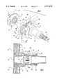
- FIG. 1is front elevational view showing a first preferred embodiment of a multi-functional apparatus employing a magnetic coupling mechanism of the present invention
- FIG. 2is an exploded perspective view showing the first preferred embodiment of a multi-functional apparatus employing a magnetic coupling mechanism of the present invention
- FIG. 3is an exploded perspective view showing the first preferred embodiment of a magnetic coupling mechanism in a multi-functional apparatus of the present invention
- FIG. 4is a perspective view, with a main gear exploded away therefrom and with an electric motor broken away therefrom, showing the first preferred embodiment of the multi-functional apparatus of the present invention
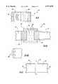
- FIG. 5is a sectional view, taken along line 5--5 of FIG. 4, showing the first preferred embodiment of a magnetic coupling mechanism of the present invention
- FIG. 6is a cross sectional view, taken along line 6--6 of FIG. 5, showing a first preferred embodiment of a solenoid segment used in a magnetic coupling mechanism of the present invention
- FIGS. 7A and 7Bare fragmentary perspective views showing the first preferred embodiment of the magnetic clutch mechanism of the present invention in an engaged and disengaged state, respectively;
- FIG. 8is a fragmentary sectional view, taken along line 5--5 of FIG. 4, showing a second preferred embodiment of a magnetic coupling mechanism of the present invention
- FIG. 9Ais a fragmentary sectional view, taken along line 5--5 of FIG. 4, showing a third preferred embodiment of a magnetic coupling mechanism of the present invention.
- FIG. 9Bis a fragmentary perspective view showing a shaft with raised members used in a third preferred embodiment of a magnetic coupling mechanism of the present invention.
- FIG. 10is a rear elevational view showing the alternative embodiment of a multi-functional apparatus employing a magnetic coupling mechanism of the present invention.
- FIG. 11is a fragmentary perspective view showing the alternative embodiment of the magnetic coupling mechanism of the present invention, illustrating a window wiper shaft being separated from an actuator shaft when a window is pivoted to an open position.
- FIG. 12is a fragmentary sectional view of an alternative embodiment of the magnetic coupling mechanism of the present invention.
- An automotive vehiclesuch as a minivan or the like, has a rear liftgate door which can pivot about an upper pair of hinges coupled to the vehicle body structure.
- a cargo spaceis accessible from behind the vehicle.
- FIG. 1Liftgate 31 has a rear window or backlite 33 pivotable between a closed position substantially flush with the outer surface of liftgate 31, to an open position about upper hinges.
- a pair of pneumatic cylinders 35act to push window 33 toward the open position when a lower portion of window 33 is released.
- a first preferred embodiment of a multi-functional apparatus 41 of the present inventionis mounted upon an inner surface of liftgate 31. The majority of apparatus 41 is hidden by an interior trim panel (not shown).
- Apparatus 41includes a central drive and power transmission unit 43, a window wiper assembly 45, a window release latch or lock 47 and a liftgate lock 49, all of which are mounted upon liftgate 31.
- FIGS. 1-4The construction of central drive and power transmission unit 43 is best illustrated in FIGS. 1-4.
- An electromagnetic devicesuch as an electric motor 51 is of a conventional fractional horsepower, dc electromagnetic variety having a metallic motor housing within which are stationary permanent magnets, a rotatable armature with wire windings, a rotatable armature shaft 53 joined to the armature, a commutator electrically connected to the wire windings and rotatable with the armature shaft, a brush card assembly and various electronic components. It will be apparent to those skilled in the art that other electric motor constructions can readily be substituted for that shown.
- a worm gear segment 55is provided upon a portion of armature shaft 53 extending beyond the motor housing.
- a gear housing 57is also provided for receiving worm gear segment 55 and the immediately adjacent portions of armature shaft 53.
- a main helical gear 59is also housed and rotatably journalled within gear housing 57.
- a collar 61stationarily extends from housing 57 co-axial with a rotational axis of helical gear 59.
- Gear housing 57is preferably made from cast aluminum.
- Helical gear 59has an external set of helically oriented teeth 71 for meshing with worm gear segment 55.
- Helical gear 59further has an internally oriented set of splines 73.
- a spring tab 75 having a driving interface surfaceis mounted upon an outer face 77 of helical gear 59 by a pair of rivets, screws, sonic welded pins, hot air cold upset pins, or the like.
- Spring tab 75is preferably stamped spring steel.
- other driving interface meansmay be employed such as an integrally molded finger, screw, rivet, compression spring, rib or other similar formations projecting from a face or peripheral portion thereof.
- Helical gear 59is preferably injection molded from a polymeric material such as acetyl.
- An electrically conducting feedback disk 81is retained to an inside face 83 of helical gear 59 through ultrasonically rolled welding or insert molding.
- Feedback disk 81is comprised of a set of copper alloy or brass stamped contacts which are provided with differing conductive and nonconductive patterns depending on the specific positional ranges as will be discussed in greater detail hereinafter.
- An electronic control module housing 91has an electronic control module shell section 93 and a gear cover section 95.
- An actuator shaft 99has a spur gear segment 101 and a carrier segment 103 divided by an annular flange 105.
- Spur gear segment 101has a set of splines 107 around an exterior peripheral surface thereof for longitudinally sliding along, while remaining enmeshed with splines 73 of helical gear 59.
- Spur gear segment 101further has an internal cylindrical passageway 109 journalized upon spindle 97 of gear cover section 95.
- a stiff compression spring 111is disposed between flange 105 and a hub of helical gear 59 for biasing actuator shaft 99 toward a driven window wiper shaft 121.
- the carrier segment 103 of actuator shaft 99is further defined with an enclosed solenoid segment 132.
- a magnetically conductive segment 140is further defined on the end of the window wiper shaft 121 which abuts the solenoid segment 132 of the actuator shaft 99.
- Actuator shaft 99 and wiper shaft 121comprise a "split shaft" construction that act in conjunction to define a magnetic coupling mechanism 130.
- Wiper shaft 121further has a distal end with threads 152 thereon upon which is attached a wiper arm 150 and nut in a conventional manner.
- Wiper shaft 121further has a circular brim 154 which provides a bearing surface upon a distal edge of collar 61.
- a cap 156 with an aperture thereinserves to retain brim 154 against collar 61.
- Actuator shaft 99is preferably powdered metal while wiper shaft 121 is made from cold rolled steel.
- window lock 47is actuated by an intermittent motion mechanism further defined as a liftgate window release lock linkage 201.
- Window linkage 201is constructed from a steel wire.
- a leading end 203 of window linkage 201is bent so as to extend through a slot 205 in gear housing 57.
- a median segment 207 of window linkage 201is linearly slidable within a passageway formed through gear housing 57.
- a trailing end 209 of window linkage 201is coupled to a window lock connecting rod 211.
- a primary lock linkage 221 and a secondary lock linkage 223are coupled to liftgate lock 49 through a connecting rod 225.
- Primary lock linkage 221is also a bent steel wire having a leading end 227 protruding within a slot 229 of hear housing 57.
- a median segment 231is slidably trapped within a support 233 extending from gear housing 57.
- a C-shaped bent wire 235couples an elbow 237 of primary lock linkage 221 to a distal end 239 of secondary lock linkage 223.
- Secondary lock linkage 223further has a proximal end 241 with a pin 243 protruding therefrom which enters and arcuate slot 245 of gear housing 57.
- Secondary lock linkage 223is pivotable about a central fulcrum 251 mounted to gear housing 57.
- Wire 235can be pivotably joined to primary and secondary lock linkages, respectively 221 and 223, via bent metal wire clips, polymeric force-fit collars, push nuts or the like.
- Linkages 209, 221 and 223may also be coupled to their respective connecting rods through similar fasteners.
- Lock linkages 221 and 223are also considered to act as intermittent motion mechanisms based on their selectively actuated operation as will be discussed hereinafter.
- Linkages 201, 221 and 223may alternately be constructed as pivoting or sliding members, having an infinite variety of shapes, and constructed from plastic, cast metal, powdered metal, bent wire, geared members or the like. It should further be understood that the connecting rods may be substituted by cables, belts, gears, a plurality of mechanical linkages, chains, jackscrews or other force transmitting and coupling means.
- electronic control moduleincludes a rear node microprocessor preferably using a Motorola MC68HCO5V6 (or alternately MC68HCO5V7) chip mounted upon a rigid printed circuit board 401.
- Rear node electronic control unit 321is electrically connected to a central body computer (not shown) in a multiplexed (MUX) fashion through a wire harness 403. AJ1850MUX protocol is used.
- An electronic control module cover 421secures electronic control unit 321 within electronic control module housing 91.
- Solenoid segmentincludes a coil configuration that electrically couples to electronic control module 321.
- a preferred coil configurationsimilar to the windings of a conventional electric motor, is shown in FIG. 6. It may be envisioned that solenoid designs with other coil configurations may also be employed to generate a magnetic force. Generally, 1-21/2 lb. of torque/square inch of surface area (with an upper limit of 10 lb./ square inch) can be achieved for transmitted force perpendicular to the magnetic path (i.e., shearing) between adjacent parts.
- Magnetically conductive segment 140is further defined as a cylinder member with an open socket 142 for receiving solenoid segment 132 of actuator shaft 99. Magnetically conductive segment 140 creates an efficient magnetic path for the field induced by internal windings 136 of the solenoid segment 132. Permanent magnets can alternatively be used as a manner to decrease the power requirements in moderate torque situations.
- magnetically conductive segment 140may be comprised of a permanently magnetic material with adjacent opposite fields as associated with the induced fields.
- the electromagnetcan be dispersed either inside or outside of the corresponding return path.
- Electrical leads 134are shown extending from a peripheral surface of solenoid segment 132. Internal to solenoid segment 132 (not shown), electrical leads may be attached to conductive rings disposed around the shaft with one lead connected to the closest ring and the other lead tunneling through the shaft to make its connection and coupled to the control system through brushes attached to the case Alternatively, one termination could connect to ground through the shaft, bushing and casing, and a second termination could be attached to a conductive ring and brush assembly as described above to complete the circuit.
- magnetic coupling mechanism 130employed with the present invention can best be understood by referring to FIGS. 7A and 7B.
- motor 51causes spring tab 75 and helical gear 59 to oscillate or reciprocate within a wiper positional range.
- solenoid segment 132 of actuator shaft 99is energized, and thus creating a magnetic coupling between solenoid segment 132 of the actuator shaft 99 and magnetically conductive segment 140 of wiper shaft 121.
- actuator shaft 99magnetically engages with wiper shaft 121 as seen if FIG. 7A. Accordingly, wiper arm 137 and wiper shaft 121 rotate in unison with actuator shaft 99 and helical gear 59.
- the electronic control unit 321instructs motor 51 to rotate helical gear 59 to a wiper arm park position. This also causes actuator shaft 99 to disengage from wiper shaft 121 as shown in FIG. 7B. By discontinuing the electric signal, solenoid segment 132 will be deenergized, and thus the magnetic force between actuator shaft 99 and wiper shaft 121 ceases.
- the wiper assemblymay be moved off the rear window and onto a holding bracket on liftgate door designated as wiper blade park/depressed position. This allows for movement of rear window without interference of the wiper assembly.
- Magnetic coupling mechanism 130enables coupling between actuator shaft 99 and wiper shaft 121 independent from the actuating of any window/liftgate locking devices.
- a multi-functional apparatusmay utilize a single motion mechanism to actuate a wiper shaft, window lock and liftgate lock. To prevent damage to the wiper, existing apparatus may not permit the liftgate and/or window to be unlocked and opened, unless the wiper blade is in a park position. However, if the window wiper is frozen onto the window or otherwise affixed in a non-park position, the single motion mechanism may not operate to allow the liftgate/window to be unlocked. Since magnetic coupling mechanism 130 is electrically controlled, the design of a multi-functional apparatus can be simplified to address these concerns.
- electronic control unit 321may disengage actuator shaft 99 from wiper shaft 121.
- electronic control unit 321may disengage actuator shaft 99 from wiper shaft 121.
- multi-functional apparatus 41deployed a single motion mechanism
- Actuator shaft 99may or may not continue to rotate, but without a magnetic coupling there will be no rotation of wiper shaft 121.
- FIGS. 8 and 9Alternative embodiments of the magnetic coupling mechanism of the present invention are shown in FIGS. 8 and 9.
- a second embodiment of magnetic coupling mechanism 180includes magnetically conductive segment 140 of wiper shaft 121 defined as having a solid cylinder member.
- solenoid segment 132 of actuator shaft 99abuts magnetically conductive segment 140 of wiper shaft 121. Since this configuration significantly decreases the contacting surface area between the two shafts, this embodiment will support low torque coupling applications. It may also be envisioned that a similar embodiment would replace solenoid segment 132 and magnetically conductive segment 140 with two permanent magnetic coupler.
- Permanent magnetic coupling devicessuch as the face-to-face torque coupling devices manufactured by Dexter Corporation, of Billerica, Mass., are then attached to the end of both actuator shaft 99 and wiper shaft 121. Use of two permanent magnetic coupling devices does not permit the engaging/disengaging functionality previously discussed, rather actuator shaft 99 and wiper shaft 121 will remain engaged.
- FIG. 9illustrates the use of a magnetic particle clutch for a third embodiment of a magnetic coupling mechanism 190 of the present invention.
- an iron cylindrical casingis used to enclose the end of each shaft.
- Electrical windings 192 along the inside circumference of casing 191will be used to generate a magnetic force.
- a segment 193 at the end of each shaftwill be comprised of ferrous material.
- an electrical signal being sent through windings 192generates the magnetic field needed to stiffen magnetic fluid 194 enclosed in casing 191 through the interaction of the micro particles to each other along the magnetic path.
- a magnetic torque couplingis created, such that actuator shaft 99 will rotate in conjunction with wiper shaft 121.
- a plurality of protruding members 195may also be defined on the end of each shaft as shown if FIG. 9B.
- FIG. 10illustrates central drive unit 43 of a multi-functional apparatus being mounted on an inner surface of liftgate, such that wiper shaft 121 (not shown) protrudes through rear window 33. Repositioning central drive unit 43 at the top of liftgate facilitates wiper arm 150 being rotated 180 degrees across window 33. It may also be envisioned that central drive unit 43 is mounted on inside surface of window 33. With regards to magnetic coupling mechanism 130, actuation shaft 99 may be coupled to wiper shaft 121 within central drive unit 43 (as previously discussed). In this case, wiper shaft 121 would extend through a hole in window 33 as best seen in FIG. 11. Moreover, magnetic coupling mechanism 130 also allows the window to be opened when wiper arm 150 is affixed in a non-park position.
- window 33can be pivoted to its open position with wiper arm 150 remaining affixed to window 33.
- wiper shaft 121is realigned with actuator shaft 99.
- a magnetic coupling mechanismallows for the coupling between the two shafts to occur through window 33 and outside central drive unit 43.
- Actuator shaft 99abuts the inner surface of a window 33 and wiper shaft 121 abuts the outer surface of window 33 (in alignment with each other). If solenoid segment 132 of actuator shaft 99 is energized a magnetic coupling occurs between the shafts through window 33, but otherwise would function as discussed above and best seen in FIG. 12.
- the magnetic coupling mechanismcan further be applied to windshield wipers, headlight wipers, side door mechanisms and other split shaft coupling applications.
- other variationsmay include a solenoid, electromagnet or other electromagnetic devices being used in place of the previously described electric motor.
- additional spur gears, pinion gears, sector gears, planetary gears, jack screws, sprockets and chains, pulleys and belts, cables or other force transmitting meansmay be employed to couple between the electromagnetic device, rotatable member, clutch mechanism, intermittent motion mechanisms or locks.
- a multiple gear transmission, linkage, belt or cable systemcan alternately couple a wiper assembly to the wiper shaft.
- the intermittent motion mechanismsmay also be accomplished by employing other known intermittent motion mechanisms such as Geneva mechanisms, starwheel mechanisms, intermittent gearing, escapements, ratchet mechanisms or other known selectively actuable devices.
- U.S. patentswhich are incorporated by reference herewithin: U.S. Pat. No. 5,228,239 entitled "System for Automatically Opening and Closing Doors of Vehicles" which issued to Heo on Jul. 20, 1993; U.S. Pat.
Landscapes
- Engineering & Computer Science (AREA)
- Mechanical Engineering (AREA)
- Power Engineering (AREA)
- General Engineering & Computer Science (AREA)
- Power-Operated Mechanisms For Wings (AREA)
Abstract
Description
Claims (16)
Priority Applications (2)
| Application Number | Priority Date | Filing Date | Title |
|---|---|---|---|
| US08/947,709US5977678A (en) | 1997-10-09 | 1997-10-09 | Magnetic coupling mechanism for use in an automotive vehicle |
| PCT/US1998/019684WO1999019189A1 (en) | 1997-10-09 | 1998-09-18 | Magnetic coupling mechanism for use in an automotive vehicle |
Applications Claiming Priority (1)
| Application Number | Priority Date | Filing Date | Title |
|---|---|---|---|
| US08/947,709US5977678A (en) | 1997-10-09 | 1997-10-09 | Magnetic coupling mechanism for use in an automotive vehicle |
Publications (1)
| Publication Number | Publication Date |
|---|---|
| US5977678Atrue US5977678A (en) | 1999-11-02 |
Family
ID=25486628
Family Applications (1)
| Application Number | Title | Priority Date | Filing Date |
|---|---|---|---|
| US08/947,709Expired - Fee RelatedUS5977678A (en) | 1997-10-09 | 1997-10-09 | Magnetic coupling mechanism for use in an automotive vehicle |
Country Status (2)
| Country | Link |
|---|---|
| US (1) | US5977678A (en) |
| WO (1) | WO1999019189A1 (en) |
Cited By (21)
| Publication number | Priority date | Publication date | Assignee | Title |
|---|---|---|---|---|
| US6255749B1 (en)* | 1999-03-30 | 2001-07-03 | Canon Kabushiki Kaisha | Motor |
| US20030079878A1 (en)* | 2001-10-26 | 2003-05-01 | Pramann James A. | Completion system, apparatus, and method |
| US20030114974A1 (en)* | 2001-10-31 | 2003-06-19 | Smith James E. | Automatic directional control system for vehicle headlights |
| US20040164634A1 (en)* | 2003-02-10 | 2004-08-26 | Siemens Vdo Automotive Inc. | Ambidextrous electronic window lift motor |
| US20040245802A1 (en)* | 2002-09-12 | 2004-12-09 | Samir Mahfoudh | Device to accommodate a latching element on a wiper drive |
| US20050116478A1 (en)* | 2003-12-02 | 2005-06-02 | Honeywell International, Inc. | Methods and systems for magnetic coupling of latch mechanisms |
| US20050121829A1 (en)* | 2003-12-03 | 2005-06-09 | Honeywell International, Inc. | Circuit insulation methods and systems for vehicle door latches |
| US20050127685A1 (en)* | 2003-12-03 | 2005-06-16 | Honeywell International Inc. | Latch control by gear position sensing |
| US20050134052A1 (en)* | 2003-12-23 | 2005-06-23 | Honeywell International Inc. | Pulsed electromagnetic application in vehicle door latch |
| US20050134053A1 (en)* | 2003-12-23 | 2005-06-23 | Honeywell International, Inc. | Storage of actuation energy in automotive door latch |
| US6949854B1 (en)* | 2001-03-16 | 2005-09-27 | Michael Schlicht | Method and apparatus for a continuously variable-ratio transmission |
| EP1220425A3 (en)* | 2000-12-27 | 2006-02-15 | Asmo Co., Ltd. | Motor having control circuit board for controlling its rotation |
| FR2881097A1 (en)* | 2005-01-26 | 2006-07-28 | Nacam France Sas | Steering column module for adjusting position of steering wheel, has steering wheel`s axial position adjusting clutch that does not utilize adjustable core magnetically interacting with electrical coil |
| US20070090654A1 (en)* | 2005-10-20 | 2007-04-26 | Honeywell International Inc. | System and method for registering the drive mechanism position of a latch apparatus after power loss |
| FR2892533A1 (en)* | 2005-10-26 | 2007-04-27 | Valeo Systemes Dessuyage | REVERSE GLASS OPENING DEVICE AND / OR VEHICLE TRUNK |
| US20080012354A1 (en)* | 2006-05-26 | 2008-01-17 | John Phillip Chevalier | Latch control by gear position sensing |
| US20120103119A1 (en)* | 2010-11-02 | 2012-05-03 | Lin cheng-da | Electrically controlable transmission for controlling the stiffness of a vehicle shock absorber |
| US20120234673A1 (en)* | 2009-09-16 | 2012-09-20 | Robert Bruce Davidson | salt water chlorinator |
| US9290252B1 (en)* | 2015-01-12 | 2016-03-22 | Brunswick Corporation | Systems and methods for controlling trim position of a marine propulsion device on a marine vessel |
| JP2019147206A (en)* | 2018-02-26 | 2019-09-05 | トヨタ自動車株式会社 | Polishing device |
| US11713024B2 (en) | 2019-08-14 | 2023-08-01 | Rosemount Aerospace Inc. | Direct drive for a windshield wiper system |
Families Citing this family (3)
| Publication number | Priority date | Publication date | Assignee | Title |
|---|---|---|---|---|
| DE19918247A1 (en)* | 1999-04-22 | 2000-10-26 | Bayerische Motoren Werke Ag | Separable coupling for driving wiper for movable rear window, with at least two carriers on drive element |
| KR20030017239A (en)* | 2001-08-24 | 2003-03-03 | 강귀병 | Joint |
| US8713746B2 (en) | 2011-01-24 | 2014-05-06 | GM Global Technology Operations LLC | Detachable rear wiper system |
Citations (104)
| Publication number | Priority date | Publication date | Assignee | Title |
|---|---|---|---|---|
| US1548016A (en)* | 1924-06-21 | 1925-07-28 | Riboisiere Jean La | Combined clutch and transmission mechanism |
| GB365603A (en) | 1930-10-22 | 1932-01-22 | Lucas Ltd Joseph | Improvements relating to wind screen wipers for motor vehicles |
| US2271207A (en)* | 1938-08-29 | 1942-01-27 | Telefunken Gmbh | Remote control arrangement |
| US2345778A (en)* | 1939-09-13 | 1944-04-04 | Johannes Antonius Van Lammeren | Remote motor control |
| GB649553A (en) | 1947-10-31 | 1951-01-31 | Us Commerce | Improvements in or relating to magnetic fluid clutch |
| DE822178C (en)* | 1950-03-15 | 1951-11-22 | Max Goller | Claw clutch for gear-regulated rollers, e.g. on paper or text machines |
| US2615945A (en)* | 1950-09-20 | 1952-10-28 | Dynamatic Corp | Field control of electromagnetic couplings |
| US2659237A (en)* | 1952-07-22 | 1953-11-17 | Harris Seybold Co | Reversing drive mechanism |
| US2722617A (en)* | 1951-11-28 | 1955-11-01 | Hartford Nat Bank & Trust Comp | Magnetic circuits and devices |
| US2953802A (en)* | 1958-01-10 | 1960-09-27 | Gen Motors Corp | Windshield cleaning system |
| US2959803A (en)* | 1958-01-10 | 1960-11-15 | Gen Motors Corp | Windshield cleaning system |
| FR1281424A (en)* | 1960-12-01 | 1962-01-12 | Windscreen washer system for motor vehicles | |
| US3163791A (en)* | 1960-04-04 | 1964-12-29 | Admiral Corp | Motor system |
| US3361005A (en)* | 1965-12-15 | 1968-01-02 | Gen Motors Corp | Headlamp actuator |
| US3361947A (en)* | 1963-02-13 | 1968-01-02 | Siteg Siebtech Gmbh | Rotary and reciprocating motor drive means for vibrating centrifuge |
| US3421380A (en)* | 1967-06-07 | 1969-01-14 | Unitek Corp | Intermittent motion apparatus |
| US3442146A (en)* | 1967-07-07 | 1969-05-06 | Theodore Simpson | Intermittent rotary motion |
| US3443455A (en)* | 1967-05-03 | 1969-05-13 | Martin J Zugel | Intermittent motion device |
| US3443442A (en)* | 1967-06-21 | 1969-05-13 | Ibm | Selectively operable intermittent motion apparatus |
| US3516610A (en)* | 1967-10-26 | 1970-06-23 | Gen Motors Corp | Windscreen wiper and washer mechanisms |
| US3523204A (en)* | 1968-01-19 | 1970-08-04 | Sydney Rand | Magnetic transmission system |
| US3574882A (en)* | 1969-07-30 | 1971-04-13 | Gen Motors Corp | Windshield washer pump assembly |
| US3619676A (en)* | 1970-03-24 | 1971-11-09 | Yaskawa Denki Seisakusho Kk | Duplex servomotor |
| US3659128A (en)* | 1969-11-17 | 1972-04-25 | Autotrol Corp | Icemaker drive with overload release |
| US3665772A (en)* | 1970-09-11 | 1972-05-30 | Ford Motor Co | Windshield wiper motor link depressed park mechanism |
| US3688332A (en)* | 1971-04-07 | 1972-09-05 | Gen Motors Corp | Mechanism for opening and closing a cover for a concealed windshield wiper system |
| US3689817A (en)* | 1971-08-09 | 1972-09-05 | Gen Motors Corp | Windshield wiper system |
| US3694723A (en)* | 1970-12-30 | 1972-09-26 | Theodor Schneider | Motor vehicle windshield wiper having a parking position outside the wiping area |
| US3705520A (en)* | 1971-10-21 | 1972-12-12 | Gen Motors Corp | Depressed park windshield wiper system |
| US3803627A (en)* | 1972-07-24 | 1974-04-09 | O Schuscheng | Motor-driven, telescoping antenna for automobiles |
| US3858922A (en)* | 1972-12-21 | 1975-01-07 | Shigehiro Yamanaka | Remote control apparatus for opening and closing vehicle door |
| US3917330A (en)* | 1972-05-25 | 1975-11-04 | Lectron Products | Electric lock release |
| US3927436A (en)* | 1973-02-19 | 1975-12-23 | Nissan Motor | Multiple-shaft double-motion drive mechanism |
| US3979619A (en)* | 1973-09-24 | 1976-09-07 | Canadian General Electric Co. Ltd. | Permanent magnet field structure for dynamoelectric machines |
| GB1448892A (en) | 1974-04-29 | 1976-09-08 | Chrysler Uk | Vehicle window wipers |
| US4009952A (en)* | 1975-01-09 | 1977-03-01 | Bell & Howell Company | Intermittent rotary motion device |
| US4065234A (en)* | 1975-12-22 | 1977-12-27 | Nihon Kagaku Kizai Kabushiki Kaisha | Magnetically driven rotary pumps |
| DE2728088A1 (en)* | 1976-06-30 | 1978-01-12 | Toyota Motor Co Ltd | WIPER SYSTEM FOR TAIL GATES |
| DE2816201A1 (en)* | 1977-04-18 | 1978-10-26 | Gen Electric | COMPOUND SUBSTRATE FOR A ROTATING ANODE OF A ROENTHINE PIPE |
| US4158159A (en)* | 1977-04-29 | 1979-06-12 | Chrysler Corporation | Electronic circuit controller for windshield wiper drive motor |
| US4173055A (en)* | 1978-11-13 | 1979-11-06 | Auto Components, Inc. | Windshield washer pump drive mechanism |
| US4183114A (en)* | 1977-01-31 | 1980-01-15 | Chrysler United Kingdom Ltd. | Rear window wiper mechanism for a motor vehicle |
| JPS5622150A (en)* | 1979-07-31 | 1981-03-02 | Fujitsu Ltd | Logic information collecting system |
| US4259624A (en)* | 1978-01-26 | 1981-03-31 | Robert Bosch Gmbh | Arrangement for wiping a vehicle window |
| US4271381A (en)* | 1978-11-30 | 1981-06-02 | Itt Industries, Inc. | Windshield wiper motor circuit |
| US4309646A (en)* | 1979-04-28 | 1982-01-05 | Itt Industries, Inc. | Control arrangement for windshield wiper apparatus |
| US4336482A (en)* | 1978-11-30 | 1982-06-22 | Itt Industries, Inc. | Rear window wiper motor control |
| US4352299A (en)* | 1978-10-16 | 1982-10-05 | The Bendix Corporation | Intermittent motion gear apparatus |
| US4422522A (en)* | 1982-01-21 | 1983-12-27 | Lectron Products, Inc. | Inertial lock for vehicle door latch |
| US4434678A (en)* | 1980-07-23 | 1984-03-06 | Gretsch-Unitas Gmbh | Control mechanism for a window or door |
| US4450390A (en)* | 1981-04-28 | 1984-05-22 | Itt Industries, Inc. | Window lifter and door locking system |
| US4478004A (en)* | 1981-03-25 | 1984-10-23 | Itt Industries, Inc. | Window lifter and door locking device |
| US4492904A (en)* | 1983-09-01 | 1985-01-08 | General Motors Corporation | Windshield wiper system with touch control |
| US4507711A (en)* | 1982-06-21 | 1985-03-26 | Nissan Motor Company, Limited | Wiper-mounted retractable head lamp assembly |
| GB2153218A (en) | 1984-01-27 | 1985-08-21 | Isringhausen Geb | Seat with multiple adjustments operable by an electric motor |
| US4553656A (en)* | 1983-10-27 | 1985-11-19 | Amerock Corporation | Power actuated operator for windows and the like |
| US4573723A (en)* | 1983-11-26 | 1986-03-04 | Nippondenso Co., Ltd. | System including bi-directional drive mechanism |
| US4630178A (en)* | 1985-12-13 | 1986-12-16 | Chrysler Motors Corporation | Articulated coupling assembly for vehicle headlamp doors |
| US4639065A (en)* | 1984-03-16 | 1987-01-27 | Swf Auto-Electric Gmbh | Windshield wiper motor |
| US4660698A (en)* | 1983-04-25 | 1987-04-28 | Tok Bearing Company, Inc. | One way clutch |
| US4674781A (en)* | 1985-12-16 | 1987-06-23 | United Technologies Electro Systems, Inc. | Electric door lock actuator |
| US4701972A (en)* | 1985-07-15 | 1987-10-27 | Saito Motors Cc., Ltd. | Rotary window cleaner |
| US4702117A (en)* | 1986-03-31 | 1987-10-27 | Kokusan Kinzoku Kogyo Kabushiki Kaisha | Lock actuator for a pair of locks |
| US4724760A (en)* | 1986-07-11 | 1988-02-16 | American Screen Printing Equipment Company | Screen press with controlled stop geneva mechanism |
| US4733147A (en)* | 1985-06-18 | 1988-03-22 | Equipements Automobiles Marchal | Control device of a direct-current electric motor for a windshield wiper |
| US4793640A (en)* | 1986-10-30 | 1988-12-27 | United Technologies Electro Systems, Inc. | Cam-actuated electric door lock |
| DE3807087A1 (en)* | 1988-03-04 | 1989-09-14 | Audi Ag | Closing device for the rear flap of a motor vehicle |
| US4875053A (en)* | 1987-09-30 | 1989-10-17 | Harada Kogyo Kabushiki Kaisha | Drive control device for an electrically-driven extending and retracting antenna |
| US4878398A (en)* | 1987-10-10 | 1989-11-07 | Robert Bosch Gmbh | Driving device for window wiper of motor vehicles |
| US4885512A (en)* | 1986-12-19 | 1989-12-05 | Swf Auto-Electric Gmbh | Wiper circuit system for motor vehicles |
| EP0345002A2 (en)* | 1988-05-31 | 1989-12-06 | Harada Industry Co., Ltd. | A clutch for an electrically driven telescopic antenna |
| US4893039A (en)* | 1987-06-12 | 1990-01-09 | Jidosha Denki Kogyo Kabushiki Kaisha | Windshield wiper motor |
| US4918272A (en)* | 1986-09-11 | 1990-04-17 | Nissan Motor Co., Ltd. | Wiper motor driving device for automotive vehicles |
| DE3923688A1 (en)* | 1989-07-18 | 1991-01-24 | Swf Auto Electric Gmbh | Lock for motor vehicle door - is actuated by crankshaft which rotates in one direction only |
| US5007131A (en)* | 1988-03-22 | 1991-04-16 | Valeo Systems D'essuyage | Blade carrying assembly for a windshield wiper including a lock |
| US5023530A (en)* | 1989-05-16 | 1991-06-11 | Jidosha Denki Kogyo K.K. | Windshield wiper motor |
| US5045741A (en)* | 1990-02-23 | 1991-09-03 | Battelle Memorial Institute | Dual-motion apparatus |
| US5063317A (en)* | 1988-11-11 | 1991-11-05 | Swf Auto-Electric Gmbh | Electric motor, especially an electric small-power motor for driving wiper systems of motor vehicles |
| US5182957A (en)* | 1989-06-24 | 1993-02-02 | Swf Auto-Electric Gmbh | Drive unit, in particular for a windshield wiper system on a motor vehicle |
| US5214440A (en)* | 1991-03-08 | 1993-05-25 | Mitsuba Electric Mfg. Co., Ltd. | Motorized antenna device |
| US5218255A (en)* | 1991-05-14 | 1993-06-08 | Jidosha Denki Kogyo Kabushiki Kaisha | Electric wiper motor with autostop mechanism |
| US5222775A (en)* | 1991-03-29 | 1993-06-29 | Ohi Seisakusho Co., Ltd. | Power operated latch device for automotive back door |
| US5228239A (en)* | 1992-05-28 | 1993-07-20 | Asia Motors Co., Inc. | System for automatically opening and closing doors of vehicles |
| US5251114A (en)* | 1990-05-25 | 1993-10-05 | Valeo Vision | Actuator for controlling the orientation of a motor vehicle headlamp |
| DE4313363A1 (en)* | 1992-04-28 | 1993-11-04 | Asmo Co Ltd | DC motor drive control circuit for vehicle windscreen wiper - selectively connects pair of motor connecting elements to electrical energy source and uses two relays for motor control |
| US5274875A (en)* | 1993-01-25 | 1994-01-04 | Chou Liao Ter | Displaceable rear windshield wiper incorporating trunk lid interaction and a rear brake light |
| US5291109A (en)* | 1990-06-12 | 1994-03-01 | Robert Bosch Gmbh | Windshield wiper system |
| DE4337760A1 (en)* | 1992-11-18 | 1994-05-19 | Valeo Systemes D Essuyage Mont | Wiper arm for opening window of vehicle - has motorised disc with slot driving pegs of lever on wiper shaft, shaft moving with window glass |
| US5315735A (en)* | 1992-12-15 | 1994-05-31 | Shin Chiu I | Opposed roller-type motor vehicle windshield wiper |
| US5333351A (en)* | 1992-08-27 | 1994-08-02 | Mitsuba Electric Mfg. Co., Ltd. | Wiper system |
| US5355286A (en)* | 1993-11-09 | 1994-10-11 | General Motors Corporation | Retractable headlamp assembly |
| US5355061A (en)* | 1992-01-24 | 1994-10-11 | Grimes Aerospace Company | Windshield wiper system |
| US5373605A (en)* | 1993-08-10 | 1994-12-20 | Austin; Lee | Lateral travel windshield wiper with speed multiplication |
| US5427345A (en)* | 1993-07-20 | 1995-06-27 | Mitsuba Electric Manufacturing Co., Ltd. | Apparatus for driving power seat for vehicle |
| US5462337A (en)* | 1992-09-04 | 1995-10-31 | Matsuba Electric Manufacturing Co., Ltd. | Power seat driving apparatus for a vehicle |
| FR2724616A1 (en)* | 1994-09-21 | 1996-03-22 | Peugeot | Windscreen wiper assembly with releasable drive connection |
| US5519258A (en)* | 1993-11-22 | 1996-05-21 | Ford Motor Company | System and method for controlling vehicle lift gate window wiper |
| US5528959A (en)* | 1993-08-24 | 1996-06-25 | Mitsuba Electric Manufacturing Co., Ltd. | Multi-driving assembly of vehicle power seat |
| US5549837A (en)* | 1994-08-31 | 1996-08-27 | Ford Motor Company | Magnetic fluid-based magnetorheological fluids |
| US5691586A (en)* | 1994-01-13 | 1997-11-25 | Schlumberger Industries, S.A. | System for providing rotary drive between two mechanical members by means of magnetic coupling, and a fluid meter including such a system |
| US5694812A (en)* | 1995-04-28 | 1997-12-09 | United Technologies Automotive, Inc. | Multi-functional apparatus employing an electromagnetic device and an intermittent motion mechanism |
| US5730028A (en)* | 1996-07-22 | 1998-03-24 | United Technologies Automotive, Inc. | Linkage for a power liftgate lock system |
| US5763981A (en)* | 1995-09-20 | 1998-06-09 | Nikon Corporation | Vibration actuator |
| US5844382A (en)* | 1997-04-09 | 1998-12-01 | Ut Automotive Dearborn, Inc | Motion transmitting apparatus for use with an automotive vehicle multi-functional apparatus |
Family Cites Families (2)
| Publication number | Priority date | Publication date | Assignee | Title |
|---|---|---|---|---|
| US8431148B2 (en) | 2007-03-08 | 2013-04-30 | Warsaw Orthopedic, Inc. | Bone void filler |
| US8430388B2 (en) | 2009-09-14 | 2013-04-30 | Jack A. Masters | Model airplane work station |
- 1997
- 1997-10-09USUS08/947,709patent/US5977678A/ennot_activeExpired - Fee Related
- 1998
- 1998-09-18WOPCT/US1998/019684patent/WO1999019189A1/enactiveApplication Filing
Patent Citations (106)
| Publication number | Priority date | Publication date | Assignee | Title |
|---|---|---|---|---|
| US1548016A (en)* | 1924-06-21 | 1925-07-28 | Riboisiere Jean La | Combined clutch and transmission mechanism |
| GB365603A (en) | 1930-10-22 | 1932-01-22 | Lucas Ltd Joseph | Improvements relating to wind screen wipers for motor vehicles |
| US2271207A (en)* | 1938-08-29 | 1942-01-27 | Telefunken Gmbh | Remote control arrangement |
| US2345778A (en)* | 1939-09-13 | 1944-04-04 | Johannes Antonius Van Lammeren | Remote motor control |
| GB649553A (en) | 1947-10-31 | 1951-01-31 | Us Commerce | Improvements in or relating to magnetic fluid clutch |
| DE822178C (en)* | 1950-03-15 | 1951-11-22 | Max Goller | Claw clutch for gear-regulated rollers, e.g. on paper or text machines |
| US2615945A (en)* | 1950-09-20 | 1952-10-28 | Dynamatic Corp | Field control of electromagnetic couplings |
| US2722617A (en)* | 1951-11-28 | 1955-11-01 | Hartford Nat Bank & Trust Comp | Magnetic circuits and devices |
| US2659237A (en)* | 1952-07-22 | 1953-11-17 | Harris Seybold Co | Reversing drive mechanism |
| US2953802A (en)* | 1958-01-10 | 1960-09-27 | Gen Motors Corp | Windshield cleaning system |
| US2959803A (en)* | 1958-01-10 | 1960-11-15 | Gen Motors Corp | Windshield cleaning system |
| US3163791A (en)* | 1960-04-04 | 1964-12-29 | Admiral Corp | Motor system |
| FR1281424A (en)* | 1960-12-01 | 1962-01-12 | Windscreen washer system for motor vehicles | |
| US3361947A (en)* | 1963-02-13 | 1968-01-02 | Siteg Siebtech Gmbh | Rotary and reciprocating motor drive means for vibrating centrifuge |
| US3361005A (en)* | 1965-12-15 | 1968-01-02 | Gen Motors Corp | Headlamp actuator |
| US3443455A (en)* | 1967-05-03 | 1969-05-13 | Martin J Zugel | Intermittent motion device |
| US3421380A (en)* | 1967-06-07 | 1969-01-14 | Unitek Corp | Intermittent motion apparatus |
| US3443442A (en)* | 1967-06-21 | 1969-05-13 | Ibm | Selectively operable intermittent motion apparatus |
| US3442146A (en)* | 1967-07-07 | 1969-05-06 | Theodore Simpson | Intermittent rotary motion |
| US3516610A (en)* | 1967-10-26 | 1970-06-23 | Gen Motors Corp | Windscreen wiper and washer mechanisms |
| US3523204A (en)* | 1968-01-19 | 1970-08-04 | Sydney Rand | Magnetic transmission system |
| US3574882A (en)* | 1969-07-30 | 1971-04-13 | Gen Motors Corp | Windshield washer pump assembly |
| US3659128A (en)* | 1969-11-17 | 1972-04-25 | Autotrol Corp | Icemaker drive with overload release |
| US3619676A (en)* | 1970-03-24 | 1971-11-09 | Yaskawa Denki Seisakusho Kk | Duplex servomotor |
| US3665772A (en)* | 1970-09-11 | 1972-05-30 | Ford Motor Co | Windshield wiper motor link depressed park mechanism |
| US3694723A (en)* | 1970-12-30 | 1972-09-26 | Theodor Schneider | Motor vehicle windshield wiper having a parking position outside the wiping area |
| US3688332A (en)* | 1971-04-07 | 1972-09-05 | Gen Motors Corp | Mechanism for opening and closing a cover for a concealed windshield wiper system |
| US3689817A (en)* | 1971-08-09 | 1972-09-05 | Gen Motors Corp | Windshield wiper system |
| US3705520A (en)* | 1971-10-21 | 1972-12-12 | Gen Motors Corp | Depressed park windshield wiper system |
| US3917330A (en)* | 1972-05-25 | 1975-11-04 | Lectron Products | Electric lock release |
| US3803627A (en)* | 1972-07-24 | 1974-04-09 | O Schuscheng | Motor-driven, telescoping antenna for automobiles |
| US3858922A (en)* | 1972-12-21 | 1975-01-07 | Shigehiro Yamanaka | Remote control apparatus for opening and closing vehicle door |
| US3927436A (en)* | 1973-02-19 | 1975-12-23 | Nissan Motor | Multiple-shaft double-motion drive mechanism |
| US3979619A (en)* | 1973-09-24 | 1976-09-07 | Canadian General Electric Co. Ltd. | Permanent magnet field structure for dynamoelectric machines |
| GB1448892A (en) | 1974-04-29 | 1976-09-08 | Chrysler Uk | Vehicle window wipers |
| US4009952A (en)* | 1975-01-09 | 1977-03-01 | Bell & Howell Company | Intermittent rotary motion device |
| US4065234A (en)* | 1975-12-22 | 1977-12-27 | Nihon Kagaku Kizai Kabushiki Kaisha | Magnetically driven rotary pumps |
| DE2728088A1 (en)* | 1976-06-30 | 1978-01-12 | Toyota Motor Co Ltd | WIPER SYSTEM FOR TAIL GATES |
| GB1580926A (en) | 1976-06-30 | 1980-12-10 | Toyota Motor Co Ltd | Wiper system for the tailgate glass of a hatchback type vehicle |
| US4183114A (en)* | 1977-01-31 | 1980-01-15 | Chrysler United Kingdom Ltd. | Rear window wiper mechanism for a motor vehicle |
| DE2816201A1 (en)* | 1977-04-18 | 1978-10-26 | Gen Electric | COMPOUND SUBSTRATE FOR A ROTATING ANODE OF A ROENTHINE PIPE |
| US4158159A (en)* | 1977-04-29 | 1979-06-12 | Chrysler Corporation | Electronic circuit controller for windshield wiper drive motor |
| US4259624A (en)* | 1978-01-26 | 1981-03-31 | Robert Bosch Gmbh | Arrangement for wiping a vehicle window |
| US4352299A (en)* | 1978-10-16 | 1982-10-05 | The Bendix Corporation | Intermittent motion gear apparatus |
| US4173055A (en)* | 1978-11-13 | 1979-11-06 | Auto Components, Inc. | Windshield washer pump drive mechanism |
| US4271381A (en)* | 1978-11-30 | 1981-06-02 | Itt Industries, Inc. | Windshield wiper motor circuit |
| US4336482A (en)* | 1978-11-30 | 1982-06-22 | Itt Industries, Inc. | Rear window wiper motor control |
| US4309646A (en)* | 1979-04-28 | 1982-01-05 | Itt Industries, Inc. | Control arrangement for windshield wiper apparatus |
| JPS5622150A (en)* | 1979-07-31 | 1981-03-02 | Fujitsu Ltd | Logic information collecting system |
| US4434678A (en)* | 1980-07-23 | 1984-03-06 | Gretsch-Unitas Gmbh | Control mechanism for a window or door |
| US4478004A (en)* | 1981-03-25 | 1984-10-23 | Itt Industries, Inc. | Window lifter and door locking device |
| US4450390A (en)* | 1981-04-28 | 1984-05-22 | Itt Industries, Inc. | Window lifter and door locking system |
| US4422522A (en)* | 1982-01-21 | 1983-12-27 | Lectron Products, Inc. | Inertial lock for vehicle door latch |
| US4507711A (en)* | 1982-06-21 | 1985-03-26 | Nissan Motor Company, Limited | Wiper-mounted retractable head lamp assembly |
| US4660698B1 (en)* | 1983-04-25 | 1992-09-15 | Tok Bearing Company Ltd | |
| US4660698A (en)* | 1983-04-25 | 1987-04-28 | Tok Bearing Company, Inc. | One way clutch |
| US4492904A (en)* | 1983-09-01 | 1985-01-08 | General Motors Corporation | Windshield wiper system with touch control |
| US4553656A (en)* | 1983-10-27 | 1985-11-19 | Amerock Corporation | Power actuated operator for windows and the like |
| US4573723A (en)* | 1983-11-26 | 1986-03-04 | Nippondenso Co., Ltd. | System including bi-directional drive mechanism |
| GB2153218A (en) | 1984-01-27 | 1985-08-21 | Isringhausen Geb | Seat with multiple adjustments operable by an electric motor |
| US4639065A (en)* | 1984-03-16 | 1987-01-27 | Swf Auto-Electric Gmbh | Windshield wiper motor |
| US4733147A (en)* | 1985-06-18 | 1988-03-22 | Equipements Automobiles Marchal | Control device of a direct-current electric motor for a windshield wiper |
| US4701972A (en)* | 1985-07-15 | 1987-10-27 | Saito Motors Cc., Ltd. | Rotary window cleaner |
| US4630178A (en)* | 1985-12-13 | 1986-12-16 | Chrysler Motors Corporation | Articulated coupling assembly for vehicle headlamp doors |
| US4674781A (en)* | 1985-12-16 | 1987-06-23 | United Technologies Electro Systems, Inc. | Electric door lock actuator |
| US4702117A (en)* | 1986-03-31 | 1987-10-27 | Kokusan Kinzoku Kogyo Kabushiki Kaisha | Lock actuator for a pair of locks |
| US4724760A (en)* | 1986-07-11 | 1988-02-16 | American Screen Printing Equipment Company | Screen press with controlled stop geneva mechanism |
| US4918272A (en)* | 1986-09-11 | 1990-04-17 | Nissan Motor Co., Ltd. | Wiper motor driving device for automotive vehicles |
| US4793640A (en)* | 1986-10-30 | 1988-12-27 | United Technologies Electro Systems, Inc. | Cam-actuated electric door lock |
| US4885512A (en)* | 1986-12-19 | 1989-12-05 | Swf Auto-Electric Gmbh | Wiper circuit system for motor vehicles |
| US4893039A (en)* | 1987-06-12 | 1990-01-09 | Jidosha Denki Kogyo Kabushiki Kaisha | Windshield wiper motor |
| US4875053A (en)* | 1987-09-30 | 1989-10-17 | Harada Kogyo Kabushiki Kaisha | Drive control device for an electrically-driven extending and retracting antenna |
| US4878398A (en)* | 1987-10-10 | 1989-11-07 | Robert Bosch Gmbh | Driving device for window wiper of motor vehicles |
| DE3807087A1 (en)* | 1988-03-04 | 1989-09-14 | Audi Ag | Closing device for the rear flap of a motor vehicle |
| US5007131A (en)* | 1988-03-22 | 1991-04-16 | Valeo Systems D'essuyage | Blade carrying assembly for a windshield wiper including a lock |
| EP0345002A2 (en)* | 1988-05-31 | 1989-12-06 | Harada Industry Co., Ltd. | A clutch for an electrically driven telescopic antenna |
| US5063317A (en)* | 1988-11-11 | 1991-11-05 | Swf Auto-Electric Gmbh | Electric motor, especially an electric small-power motor for driving wiper systems of motor vehicles |
| US5023530A (en)* | 1989-05-16 | 1991-06-11 | Jidosha Denki Kogyo K.K. | Windshield wiper motor |
| US5182957A (en)* | 1989-06-24 | 1993-02-02 | Swf Auto-Electric Gmbh | Drive unit, in particular for a windshield wiper system on a motor vehicle |
| DE3923688A1 (en)* | 1989-07-18 | 1991-01-24 | Swf Auto Electric Gmbh | Lock for motor vehicle door - is actuated by crankshaft which rotates in one direction only |
| US5045741A (en)* | 1990-02-23 | 1991-09-03 | Battelle Memorial Institute | Dual-motion apparatus |
| US5251114A (en)* | 1990-05-25 | 1993-10-05 | Valeo Vision | Actuator for controlling the orientation of a motor vehicle headlamp |
| US5291109A (en)* | 1990-06-12 | 1994-03-01 | Robert Bosch Gmbh | Windshield wiper system |
| US5214440A (en)* | 1991-03-08 | 1993-05-25 | Mitsuba Electric Mfg. Co., Ltd. | Motorized antenna device |
| US5222775A (en)* | 1991-03-29 | 1993-06-29 | Ohi Seisakusho Co., Ltd. | Power operated latch device for automotive back door |
| US5218255A (en)* | 1991-05-14 | 1993-06-08 | Jidosha Denki Kogyo Kabushiki Kaisha | Electric wiper motor with autostop mechanism |
| US5355061A (en)* | 1992-01-24 | 1994-10-11 | Grimes Aerospace Company | Windshield wiper system |
| DE4313363A1 (en)* | 1992-04-28 | 1993-11-04 | Asmo Co Ltd | DC motor drive control circuit for vehicle windscreen wiper - selectively connects pair of motor connecting elements to electrical energy source and uses two relays for motor control |
| US5228239A (en)* | 1992-05-28 | 1993-07-20 | Asia Motors Co., Inc. | System for automatically opening and closing doors of vehicles |
| US5333351A (en)* | 1992-08-27 | 1994-08-02 | Mitsuba Electric Mfg. Co., Ltd. | Wiper system |
| US5462337A (en)* | 1992-09-04 | 1995-10-31 | Matsuba Electric Manufacturing Co., Ltd. | Power seat driving apparatus for a vehicle |
| DE4337760A1 (en)* | 1992-11-18 | 1994-05-19 | Valeo Systemes D Essuyage Mont | Wiper arm for opening window of vehicle - has motorised disc with slot driving pegs of lever on wiper shaft, shaft moving with window glass |
| US5315735A (en)* | 1992-12-15 | 1994-05-31 | Shin Chiu I | Opposed roller-type motor vehicle windshield wiper |
| US5274875A (en)* | 1993-01-25 | 1994-01-04 | Chou Liao Ter | Displaceable rear windshield wiper incorporating trunk lid interaction and a rear brake light |
| US5427345A (en)* | 1993-07-20 | 1995-06-27 | Mitsuba Electric Manufacturing Co., Ltd. | Apparatus for driving power seat for vehicle |
| US5373605A (en)* | 1993-08-10 | 1994-12-20 | Austin; Lee | Lateral travel windshield wiper with speed multiplication |
| US5528959A (en)* | 1993-08-24 | 1996-06-25 | Mitsuba Electric Manufacturing Co., Ltd. | Multi-driving assembly of vehicle power seat |
| US5355286A (en)* | 1993-11-09 | 1994-10-11 | General Motors Corporation | Retractable headlamp assembly |
| US5519258A (en)* | 1993-11-22 | 1996-05-21 | Ford Motor Company | System and method for controlling vehicle lift gate window wiper |
| US5691586A (en)* | 1994-01-13 | 1997-11-25 | Schlumberger Industries, S.A. | System for providing rotary drive between two mechanical members by means of magnetic coupling, and a fluid meter including such a system |
| US5549837A (en)* | 1994-08-31 | 1996-08-27 | Ford Motor Company | Magnetic fluid-based magnetorheological fluids |
| FR2724616A1 (en)* | 1994-09-21 | 1996-03-22 | Peugeot | Windscreen wiper assembly with releasable drive connection |
| US5694812A (en)* | 1995-04-28 | 1997-12-09 | United Technologies Automotive, Inc. | Multi-functional apparatus employing an electromagnetic device and an intermittent motion mechanism |
| US5763981A (en)* | 1995-09-20 | 1998-06-09 | Nikon Corporation | Vibration actuator |
| US5730028A (en)* | 1996-07-22 | 1998-03-24 | United Technologies Automotive, Inc. | Linkage for a power liftgate lock system |
| US5844382A (en)* | 1997-04-09 | 1998-12-01 | Ut Automotive Dearborn, Inc | Motion transmitting apparatus for use with an automotive vehicle multi-functional apparatus |
Non-Patent Citations (62)
| Title |
|---|
| "Automotive Handbook", Bosch 3rd Edition, 1993, pp. 694-697. |
| "Genevamation Indexing Drives", Jan. 12, 1995 Catalog No. 693, Geneva Mechanisms Corporation. |
| "Goodheart-Wilcox Automotive Encyclopedia", William K. Toboldt, Larry Johnson, Steven W. Olive, 1989, pp. 723-727. |
| "Kinematic Analysis of Mechanisms", 1959, J.E. Shigley, pp. 228-231. |
| "Kinematics of Intermittent Mechanisms III--The Spherical Geneva Wheel", Product Engineering, Oct. 1949, S. Rappaport, pp. 137-139. |
| "Mechanisms and Dynamics of Machinery", Hamilton H. Mabie and Fred W. Ocvirk, John Wiley & Sons, 1957. |
| "Mechanisms for Engineering Design" "Motion, Circular, Intermittent", Chapter 3, S.B. Tuttle, John Wiley Co., pp. 33-51. |
| "Mechanisms for Providing Intermittent Rotary Motion", Product Engineering, Aug. 1949, pp. 116-117. |
| "Saab 900 Owners Workshop Manual", Haynes Publishing Group, 1979 through 1985, pp. 172-174, 237. |
| A paper from the International Congress & Exposition, SAE Technical Paper Series 960390, "Liftgate Multiplexed Node", Feb., 1996, H. Winston Maue, pp. 73-76. |
| A paper from the International Congress & Exposition, SAE Technical Paper Series 960390, Liftgate Multiplexed Node , Feb., 1996, H. Winston Maue, pp. 73 76.* |
| A paper from the Third Conference Mechanisms, "A Survey of Intermittent-Motion", F.J.Bogardus, 1956, pp. 8-15. |
| A paper from the Third Conference Mechanisms, A Survey of Intermittent Motion , F.J.Bogardus, 1956, pp. 8 15.* |
| A paper from the Third Conference on Mechanisms, "Designing for Intermittent Motion with Modified Starwheels", Karl E. Kist, pp. 16-20. |
| A paper from the Third Conference on Mechanisms, Designing for Intermittent Motion with Modified Starwheels , Karl E. Kist, pp. 16 20.* |
| Automotive Handbook , Bosch 3rd Edition, 1993, pp. 694 697.* |
| Exhibit A (UTA 26 Gate Wiper Motor), prior to Oct. 9, 1997.* |
| Exhibit A--(UTA 26 Gate Wiper Motor), prior to Oct. 9, 1997. |
| Exhibit B (1996 Ford Windstar Wiper Motor), prior to Oct. 9, 1997.* |
| Exhibit B--(1996 Ford Windstar Wiper Motor), prior to Oct. 9, 1997. |
| Exhibit C (1996 Chevy Blazer Wiper Motor), prior to Oct. 9, 1997.* |
| Exhibit C--(1996 Chevy Blazer Wiper Motor), prior to Oct. 9, 1997. |
| Exhibit D (1996 Honda Civic Rear Unidirectional Wiper Motor), prior to Oct. 9, 1997.* |
| Exhibit D--(1996 Honda Civic Rear Unidirectional Wiper Motor), prior to Oct. 9, 1997. |
| Exhibit E (1996 Toyota Direct Drive Unidirectional Wiper Motor), prior to Oct. 9, 1997.* |
| Exhibit E--(1996 Toyota Direct Drive Unidirectional Wiper Motor), prior to Oct. 9, 1997. |
| Exhibit F (1996 Honda Civic Wiper Motor), prior to Oct. 9, 1997.* |
| Exhibit F--(1996 Honda Civic Wiper Motor), prior to Oct. 9, 1997. |
| Exhibit G (Wiper Motor), prior to Oct. 9, 1997.* |
| Exhibit G--(Wiper Motor), prior to Oct. 9, 1997. |
| Exhibit H (Wiper Motor), prior to Oct. 9, 2997.* |
| Exhibit H--(Wiper Motor), prior to Oct. 9, 2997. |
| Genevamation Indexing Drives , Jan. 12, 1995 Catalog No. 693, Geneva Mechanisms Corporation.* |
| Goodheart Wilcox Automotive Encyclopedia , William K. Toboldt, Larry Johnson, Steven W. Olive, 1989, pp. 723 727.* |
| Kinematic Analysis of Mechanisms , 1959, J.E. Shigley, pp. 228 231.* |
| Kinematics of Intermittent Mechanisms III The Spherical Geneva Wheel , Product Engineering, Oct. 1949, S. Rappaport, pp. 137 139.* |
| Machine Design, "Mechanical Systems", Jun. 1992, pp. 130, 132, 168. |
| Machine Design, "Mechanism for Intermittent Motion, Part 3", Feb. 1952, Otto Lichtwitz, pp. 146-155. |
| Machine Design, "Mechanisms for Intermittent Motion, Part 2", Jan. 1952, Otto Lichtwitz, pp. 127-141. |
| Machine Design, "Mechanisms for Intermittent Motion, Part 4", Mar. 1952, Otto Lichtwitz, pp. 147-155. |
| Machine Design, "Modifying Starwheel Mechanisms", Vandeman and Wood, Apr. 1953, pp. 255-261. |
| Machine Design, Mechanical Systems , Jun. 1992, pp. 130, 132, 168.* |
| Machine Design, Mechanism for Intermittent Motion, Part 3 , Feb. 1952, Otto Lichtwitz, pp. 146 155.* |
| Machine Design, Mechanisms for Intermittent Motion, Part 2 , Jan. 1952, Otto Lichtwitz, pp. 127 141.* |
| Machine Design, Mechanisms for Intermittent Motion, Part 4 , Mar. 1952, Otto Lichtwitz, pp. 147 155.* |
| Machine Design, Mechansims for Intermittent Motion, Dec. 1951, Otto Lichtwitz, pp. 134 148.* |
| Machine Design, Mechansims for Intermittent Motion, Dec. 1951, Otto Lichtwitz, pp. 134-148. |
| Machine Design, Modifying Starwheel Mechanisms , Vandeman and Wood, Apr. 1953, pp. 255 261.* |
| Mechanisms and Dynamics of Machinery , Hamilton H. Mabie and Fred W. Ocvirk, John Wiley & Sons, 1957.* |
| Mechanisms for Engineering Design Motion, Circular, Intermittent , Chapter 3, S.B. Tuttle, John Wiley Co., pp. 33 51.* |
| Mechanisms for Providing Intermittent Rotary Motion , Product Engineering, Aug. 1949, pp. 116 117.* |
| Mechine Deisgn, "Basics of Design Engineering," Jun. 1992, Article "Mechanical Systems". |
| Mechine Deisgn, Basics of Design Engineering, Jun. 1992, Article Mechanical Systems .* |
| Page 100, Machine Design, 60 (1988) Oct. 13, No. 24, Cleveland, Ohio, US.* |
| Patent Abstracts of Japan, vol. 016, 7 438 (M 1309), Sep. 11, 1992 for JP Patent Publication No. 04151351.* |
| Patent Abstracts of Japan, vol. 016, 7-438 (M-1309), Sep. 11, 1992 for JP Patent Publication No. 04151351. |
| PCT International Search Report dated Feb. 11, 1999.* |
| Permag Corp./Dexter Corp. Quotation; May 25, 1994.* |
| Saab 900 Owners Workshop Manual , Haynes Publishing Group, 1979 through 1985, pp. 172 174, 237.* |
| UTRC Notes, Nov. 5, 1993.* |
| Warner Electric UniModule Advertisement (prior to Oct. 9, 1997).* |
| Warner Electric UniModule® Advertisement (prior to Oct. 9, 1997). |
Cited By (29)
| Publication number | Priority date | Publication date | Assignee | Title |
|---|---|---|---|---|
| US6255749B1 (en)* | 1999-03-30 | 2001-07-03 | Canon Kabushiki Kaisha | Motor |
| EP1220425A3 (en)* | 2000-12-27 | 2006-02-15 | Asmo Co., Ltd. | Motor having control circuit board for controlling its rotation |
| US6949854B1 (en)* | 2001-03-16 | 2005-09-27 | Michael Schlicht | Method and apparatus for a continuously variable-ratio transmission |
| US20030079878A1 (en)* | 2001-10-26 | 2003-05-01 | Pramann James A. | Completion system, apparatus, and method |
| US20030114974A1 (en)* | 2001-10-31 | 2003-06-19 | Smith James E. | Automatic directional control system for vehicle headlights |
| US7241034B2 (en) | 2001-10-31 | 2007-07-10 | Dana Corporation | Automatic directional control system for vehicle headlights |
| US6981732B2 (en)* | 2002-09-12 | 2006-01-03 | Robert Bosch Gmbh | Device to accommodate a latching element on a wiper drive |
| US20040245802A1 (en)* | 2002-09-12 | 2004-12-09 | Samir Mahfoudh | Device to accommodate a latching element on a wiper drive |
| US20040164634A1 (en)* | 2003-02-10 | 2004-08-26 | Siemens Vdo Automotive Inc. | Ambidextrous electronic window lift motor |
| US7098562B2 (en)* | 2003-02-10 | 2006-08-29 | Siemens Vdo Automotive Corporation | Ambidextrous electronic window lift motor |
| US20050116478A1 (en)* | 2003-12-02 | 2005-06-02 | Honeywell International, Inc. | Methods and systems for magnetic coupling of latch mechanisms |
| US20050127685A1 (en)* | 2003-12-03 | 2005-06-16 | Honeywell International Inc. | Latch control by gear position sensing |
| US20050121829A1 (en)* | 2003-12-03 | 2005-06-09 | Honeywell International, Inc. | Circuit insulation methods and systems for vehicle door latches |
| US20050134052A1 (en)* | 2003-12-23 | 2005-06-23 | Honeywell International Inc. | Pulsed electromagnetic application in vehicle door latch |
| US20050134053A1 (en)* | 2003-12-23 | 2005-06-23 | Honeywell International, Inc. | Storage of actuation energy in automotive door latch |
| FR2881097A1 (en)* | 2005-01-26 | 2006-07-28 | Nacam France Sas | Steering column module for adjusting position of steering wheel, has steering wheel`s axial position adjusting clutch that does not utilize adjustable core magnetically interacting with electrical coil |
| US20070090654A1 (en)* | 2005-10-20 | 2007-04-26 | Honeywell International Inc. | System and method for registering the drive mechanism position of a latch apparatus after power loss |
| US20080276536A1 (en)* | 2005-10-26 | 2008-11-13 | Valeo Systemes D'essuyage | Device for Opening a Rear Window and/or Trunk of a Vehicle |
| WO2007048602A1 (en)* | 2005-10-26 | 2007-05-03 | Valeo Systemes D'essuyage | Device for opening a rear window and/or trunk of a vehicle |
| FR2892533A1 (en)* | 2005-10-26 | 2007-04-27 | Valeo Systemes Dessuyage | REVERSE GLASS OPENING DEVICE AND / OR VEHICLE TRUNK |
| JP2009513851A (en)* | 2005-10-26 | 2009-04-02 | ヴァレオ システム デシュヤージュ | Device for opening the rear window or trunk of a vehicle |
| US20080012354A1 (en)* | 2006-05-26 | 2008-01-17 | John Phillip Chevalier | Latch control by gear position sensing |
| US20120234673A1 (en)* | 2009-09-16 | 2012-09-20 | Robert Bruce Davidson | salt water chlorinator |
| US8920615B2 (en)* | 2009-09-16 | 2014-12-30 | Davey Water Products Pty Ltd | Salt water chlorinator |
| US20120103119A1 (en)* | 2010-11-02 | 2012-05-03 | Lin cheng-da | Electrically controlable transmission for controlling the stiffness of a vehicle shock absorber |
| US9290252B1 (en)* | 2015-01-12 | 2016-03-22 | Brunswick Corporation | Systems and methods for controlling trim position of a marine propulsion device on a marine vessel |
| JP2019147206A (en)* | 2018-02-26 | 2019-09-05 | トヨタ自動車株式会社 | Polishing device |
| US11713024B2 (en) | 2019-08-14 | 2023-08-01 | Rosemount Aerospace Inc. | Direct drive for a windshield wiper system |
| US12049200B2 (en) | 2019-08-14 | 2024-07-30 | Rosemount Aerospace Inc. | Direct drive for a windshield wiper system |
Also Published As
| Publication number | Publication date |
|---|---|
| WO1999019189A1 (en) | 1999-04-22 |
Similar Documents
| Publication | Publication Date | Title |
|---|---|---|
| US5977678A (en) | Magnetic coupling mechanism for use in an automotive vehicle | |
| US6116110A (en) | Multi-functional apparatus employing an electro-magnetic device and an intermittent motion mechanism | |
| US5905345A (en) | Multi-functional apparatus employing an intermittent motion mechanism | |
| US5907199A (en) | Electric motor providing multi-directional output | |
| US6075298A (en) | Rotary and linear translation actuator performing multi-functions in an automobile | |
| US5924324A (en) | Movable gear drive windshield wiper | |
| US5764010A (en) | Control system for an automotive vehicle multi-functional apparatus | |
| US5979256A (en) | Gear drive window wiper and multi-function electric motor | |
| US6018223A (en) | Multi-functional apparatus employing an intermittent motion mechanism | |
| US6205612B1 (en) | Window wiper system for an automotive vehicle | |
| US6003193A (en) | Multi-functional apparatus having flexible clutch | |
| US5920159A (en) | Multi-functional apparatus employing a flexible drive element for selectively actuating multiple output systems | |
| US5920158A (en) | Multi-functional vehicle apparatus | |
| US6195940B1 (en) | Power actuator for a vehicle window | |
| US6449798B1 (en) | Multi-function apparatus having flexible clutch | |
| US5847519A (en) | Multi-functional apparatus for a wiper and cable drive | |
| US5916327A (en) | Multi-functional apparatus employing an electromagnetic device | |
| US5969431A (en) | Linearly actuating multi-functional apparatus for use in an automotive vehicle | |
| US5889341A (en) | Multi-functional apparatus employing a linear wiper | |
| US5953786A (en) | Bypass loop wiper/washer system |
Legal Events
| Date | Code | Title | Description |
|---|---|---|---|
| AS | Assignment | Owner name:UT AUTOMOTIVE DEARBORN, INC. (A DELAWARE CORPORATI Free format text:ASSIGNMENT OF ASSIGNORS INTEREST;ASSIGNOR:UNITED TECHNOLOGIES AUTOMOTIVE, INC.;REEL/FRAME:009119/0228 Effective date:19980309 | |
| AS | Assignment | Owner name:LEAR AUTOMOTIVE DEARBORN, INC., MICHIGAN Free format text:CHANGE OF NAME;ASSIGNOR:UT AUTOMOTIVE DEARBORN, INC.;REEL/FRAME:010133/0411 Effective date:19990617 | |
| FEPP | Fee payment procedure | Free format text:PAYOR NUMBER ASSIGNED (ORIGINAL EVENT CODE: ASPN); ENTITY STATUS OF PATENT OWNER: LARGE ENTITY | |
| FPAY | Fee payment | Year of fee payment:4 | |
| AS | Assignment | Owner name:LEAR AUTOMOTIVE DEARBORN, INC., MICHIGAN Free format text:CHANGE OF NAME;ASSIGNOR:UT AUTOMOTIVE DEARBORN, INC.;REEL/FRAME:014172/0756 Effective date:19990617 | |
| AS | Assignment | Owner name:LEAR CORPORATION, MICHIGAN Free format text:ASSIGNMENT OF ASSIGNORS INTEREST;ASSIGNORS:MILLER, ROBIN MIHEKUN;FALCOFF, MONTE L.;REEL/FRAME:017804/0905 Effective date:19971009 | |
| AS | Assignment | Owner name:JPMORGAN CHASE BANK, N.A., AS GENERAL ADMINISTRATI Free format text:SECURITY AGREEMENT;ASSIGNOR:LEAR AUTOMOTIVE DEARBORN, INC.;REEL/FRAME:017823/0950 Effective date:20060425 | |
| AS | Assignment | Owner name:UNITED TECHNOLOGIES AUTOMOTIVE, INC., MICHIGAN Free format text:CORRECTIVE ASSIGNMENT TO CORRECT MISTAKE IN THE ASSIGNEE FROM LEAR CORPORATION TO UNITED TECHNOLOGIES AUTOMOTIVE, INC. PREVIOUSYL RECORDED AT REEL 017804 FRAME 0905;ASSIGNORS:MILLER, ROBIN MIHEKUN;FALCOFF, MONTE L.;REEL/FRAME:018480/0301 Effective date:19971009 | |
| REMI | Maintenance fee reminder mailed | ||
| LAPS | Lapse for failure to pay maintenance fees | ||
| STCH | Information on status: patent discontinuation | Free format text:PATENT EXPIRED DUE TO NONPAYMENT OF MAINTENANCE FEES UNDER 37 CFR 1.362 | |
| FP | Lapsed due to failure to pay maintenance fee | Effective date:20071102 | |
| AS | Assignment | Owner name:LEAR AUTOMOTIVE DEARBORN, INC., MICHIGAN Free format text:RELEASE BY SECURED PARTY;ASSIGNOR:JPMORGAN CHASE BANK, N.A.;REEL/FRAME:032712/0428 Effective date:20100830 |