US5976178A - Medical grafting methods - Google Patents
Medical grafting methodsDownload PDFInfo
- Publication number
- US5976178A US5976178AUS08/745,618US74561896AUS5976178AUS 5976178 AUS5976178 AUS 5976178AUS 74561896 AUS74561896 AUS 74561896AUS 5976178 AUS5976178 AUS 5976178A
- Authority
- US
- United States
- Prior art keywords
- length
- tubing
- graft
- section
- method defined
- Prior art date
- Legal status (The legal status is an assumption and is not a legal conclusion. Google has not performed a legal analysis and makes no representation as to the accuracy of the status listed.)
- Expired - Lifetime
Links
- 238000000034methodMethods0.000titleclaimsabstractdescription119
- 210000000056organAnatomy0.000claimsabstractdescription49
- 230000003872anastomosisEffects0.000claimsdescription5
- 230000000630rising effectEffects0.000claims1
- 238000001356surgical procedureMethods0.000abstract1
- 210000004351coronary vesselAnatomy0.000description53
- 210000000709aortaAnatomy0.000description51
- 239000000463materialSubstances0.000description24
- 238000000576coating methodMethods0.000description20
- 238000010276constructionMethods0.000description13
- 210000001367arteryAnatomy0.000description9
- 239000002184metalSubstances0.000description9
- 239000011248coating agentSubstances0.000description7
- 239000013013elastic materialSubstances0.000description7
- HLXZNVUGXRDIFK-UHFFFAOYSA-Nnickel titaniumChemical compound[Ti].[Ti].[Ti].[Ti].[Ti].[Ti].[Ti].[Ti].[Ti].[Ti].[Ti].[Ni].[Ni].[Ni].[Ni].[Ni].[Ni].[Ni].[Ni].[Ni].[Ni].[Ni].[Ni].[Ni].[Ni]HLXZNVUGXRDIFK-UHFFFAOYSA-N0.000description6
- 229910001000nickel titaniumInorganic materials0.000description6
- 229910001220stainless steelInorganic materials0.000description6
- 239000010935stainless steelSubstances0.000description6
- 239000000835fiberSubstances0.000description5
- 239000012530fluidSubstances0.000description5
- 230000000472traumatic effectEffects0.000description5
- 230000008901benefitEffects0.000description4
- 210000001105femoral arteryAnatomy0.000description4
- 238000009434installationMethods0.000description4
- 239000011236particulate materialSubstances0.000description4
- 229920000642polymerPolymers0.000description4
- 229920001296polysiloxanePolymers0.000description4
- 230000004044responseEffects0.000description4
- 210000003752saphenous veinAnatomy0.000description4
- 230000017531blood circulationEffects0.000description3
- 239000003795chemical substances by applicationSubstances0.000description3
- 229940079593drugDrugs0.000description3
- 239000003814drugSubstances0.000description3
- 210000001349mammary arteryAnatomy0.000description3
- 239000002245particleSubstances0.000description3
- 230000010412perfusionEffects0.000description3
- 229920001343polytetrafluoroethylenePolymers0.000description3
- 239000004810polytetrafluoroethyleneSubstances0.000description3
- 239000011148porous materialSubstances0.000description3
- 230000008439repair processEffects0.000description3
- 230000001502supplementing effectEffects0.000description3
- 238000009834vaporizationMethods0.000description3
- 230000008016vaporizationEffects0.000description3
- 208000031104Arterial Occlusive diseaseDiseases0.000description2
- 102000008186CollagenHuman genes0.000description2
- 108010035532CollagenProteins0.000description2
- 239000004372Polyvinyl alcoholSubstances0.000description2
- WYTGDNHDOZPMIW-RCBQFDQVSA-NalstonineNatural productsC1=CC2=C3C=CC=CC3=NC2=C2N1C[C@H]1[C@H](C)OC=C(C(=O)OC)[C@H]1C2WYTGDNHDOZPMIW-RCBQFDQVSA-N0.000description2
- 238000004873anchoringMethods0.000description2
- 208000021328arterial occlusionDiseases0.000description2
- 239000008280bloodSubstances0.000description2
- 210000004369bloodAnatomy0.000description2
- 210000004204blood vesselAnatomy0.000description2
- 210000002302brachial arteryAnatomy0.000description2
- 210000004027cellAnatomy0.000description2
- 229920001436collagenPolymers0.000description2
- 210000005260human cellAnatomy0.000description2
- 238000007373indentationMethods0.000description2
- 230000007246mechanismEffects0.000description2
- 238000012986modificationMethods0.000description2
- 230000004048modificationEffects0.000description2
- 238000010899nucleationMethods0.000description2
- RVTZCBVAJQQJTK-UHFFFAOYSA-Noxygen(2-);zirconium(4+)Chemical compound[O-2].[O-2].[Zr+4]RVTZCBVAJQQJTK-UHFFFAOYSA-N0.000description2
- 229920002451polyvinyl alcoholPolymers0.000description2
- 229920002379silicone rubberPolymers0.000description2
- 239000004945silicone rubberSubstances0.000description2
- 210000000115thoracic cavityAnatomy0.000description2
- 238000012546transferMethods0.000description2
- XLYOFNOQVPJJNP-UHFFFAOYSA-NwaterSubstancesOXLYOFNOQVPJJNP-UHFFFAOYSA-N0.000description2
- ATRRKUHOCOJYRX-UHFFFAOYSA-NAmmonium bicarbonateChemical compound[NH4+].OC([O-])=OATRRKUHOCOJYRX-UHFFFAOYSA-N0.000description1
- JOYRKODLDBILNP-UHFFFAOYSA-NEthyl urethaneChemical compoundCCOC(N)=OJOYRKODLDBILNP-UHFFFAOYSA-N0.000description1
- HTTJABKRGRZYRN-UHFFFAOYSA-NHeparinChemical compoundOC1C(NC(=O)C)C(O)OC(COS(O)(=O)=O)C1OC1C(OS(O)(=O)=O)C(O)C(OC2C(C(OS(O)(=O)=O)C(OC3C(C(O)C(O)C(O3)C(O)=O)OS(O)(=O)=O)C(CO)O2)NS(O)(=O)=O)C(C(O)=O)O1HTTJABKRGRZYRN-UHFFFAOYSA-N0.000description1
- 244000043261Hevea brasiliensisSpecies0.000description1
- 208000007536ThrombosisDiseases0.000description1
- -1ammonium carbonateChemical class0.000description1
- 235000012501ammonium carbonateNutrition0.000description1
- 239000001099ammonium carbonateSubstances0.000description1
- 239000003146anticoagulant agentSubstances0.000description1
- 229940127219anticoagulant drugDrugs0.000description1
- 238000013459approachMethods0.000description1
- 238000010009beatingMethods0.000description1
- 230000009286beneficial effectEffects0.000description1
- 239000000560biocompatible materialSubstances0.000description1
- 238000001574biopsyMethods0.000description1
- 238000009835boilingMethods0.000description1
- 238000009954braidingMethods0.000description1
- 230000000747cardiac effectEffects0.000description1
- 210000000038chestAnatomy0.000description1
- 238000011161developmentMethods0.000description1
- 238000007598dipping methodMethods0.000description1
- 230000000694effectsEffects0.000description1
- 229920001971elastomerPolymers0.000description1
- 238000007590electrostatic sprayingMethods0.000description1
- 230000003511endothelial effectEffects0.000description1
- 238000009950feltingMethods0.000description1
- 238000002695general anesthesiaMethods0.000description1
- 238000009499grossingMethods0.000description1
- 229960002897heparinDrugs0.000description1
- 229920000669heparinPolymers0.000description1
- 238000005286illuminationMethods0.000description1
- 238000002513implantationMethods0.000description1
- 238000000338in vitroMethods0.000description1
- 208000014674injuryDiseases0.000description1
- 238000009940knittingMethods0.000description1
- 239000007788liquidSubstances0.000description1
- 210000004072lungAnatomy0.000description1
- 238000004519manufacturing processMethods0.000description1
- 229920003052natural elastomerPolymers0.000description1
- 229920001194natural rubberPolymers0.000description1
- 230000000926neurological effectEffects0.000description1
- 230000003287optical effectEffects0.000description1
- 230000000149penetrating effectEffects0.000description1
- 230000002093peripheral effectEffects0.000description1
- 239000004033plasticSubstances0.000description1
- 229920003023plasticPolymers0.000description1
- 229920000052poly(p-xylylene)Polymers0.000description1
- 239000002861polymer materialSubstances0.000description1
- 229920002635polyurethanePolymers0.000description1
- 239000004814polyurethaneSubstances0.000description1
- 230000008569processEffects0.000description1
- 238000009877renderingMethods0.000description1
- 230000000717retained effectEffects0.000description1
- 150000003839saltsChemical class0.000description1
- 238000000926separation methodMethods0.000description1
- 239000002904solventSubstances0.000description1
- 239000013589supplementSubstances0.000description1
- 230000008733traumaEffects0.000description1
- 210000003462veinAnatomy0.000description1
- 230000000007visual effectEffects0.000description1
- 238000009941weavingMethods0.000description1
Images


Classifications
- A—HUMAN NECESSITIES
- A61—MEDICAL OR VETERINARY SCIENCE; HYGIENE
- A61B—DIAGNOSIS; SURGERY; IDENTIFICATION
- A61B1/00—Instruments for performing medical examinations of the interior of cavities or tubes of the body by visual or photographical inspection, e.g. endoscopes; Illuminating arrangements therefor
- A61B1/005—Flexible endoscopes
- A61B1/0058—Flexible endoscopes using shape-memory elements
- A—HUMAN NECESSITIES
- A61—MEDICAL OR VETERINARY SCIENCE; HYGIENE
- A61B—DIAGNOSIS; SURGERY; IDENTIFICATION
- A61B17/00—Surgical instruments, devices or methods
- A61B17/22—Implements for squeezing-off ulcers or the like on inner organs of the body; Implements for scraping-out cavities of body organs, e.g. bones; for invasive removal or destruction of calculus using mechanical vibrations; for removing obstructions in blood vessels, not otherwise provided for
- A61B17/221—Gripping devices in the form of loops or baskets for gripping calculi or similar types of obstructions
- A—HUMAN NECESSITIES
- A61—MEDICAL OR VETERINARY SCIENCE; HYGIENE
- A61B—DIAGNOSIS; SURGERY; IDENTIFICATION
- A61B17/00—Surgical instruments, devices or methods
- A61B17/32—Surgical cutting instruments
- A61B17/3205—Excision instruments
- A61B17/32056—Surgical snare instruments
- A—HUMAN NECESSITIES
- A61—MEDICAL OR VETERINARY SCIENCE; HYGIENE
- A61F—FILTERS IMPLANTABLE INTO BLOOD VESSELS; PROSTHESES; DEVICES PROVIDING PATENCY TO, OR PREVENTING COLLAPSING OF, TUBULAR STRUCTURES OF THE BODY, e.g. STENTS; ORTHOPAEDIC, NURSING OR CONTRACEPTIVE DEVICES; FOMENTATION; TREATMENT OR PROTECTION OF EYES OR EARS; BANDAGES, DRESSINGS OR ABSORBENT PADS; FIRST-AID KITS
- A61F2/00—Filters implantable into blood vessels; Prostheses, i.e. artificial substitutes or replacements for parts of the body; Appliances for connecting them with the body; Devices providing patency to, or preventing collapsing of, tubular structures of the body, e.g. stents
- A61F2/02—Prostheses implantable into the body
- A61F2/04—Hollow or tubular parts of organs, e.g. bladders, tracheae, bronchi or bile ducts
- A61F2/06—Blood vessels
- A61F2/064—Blood vessels with special features to facilitate anastomotic coupling
- A—HUMAN NECESSITIES
- A61—MEDICAL OR VETERINARY SCIENCE; HYGIENE
- A61F—FILTERS IMPLANTABLE INTO BLOOD VESSELS; PROSTHESES; DEVICES PROVIDING PATENCY TO, OR PREVENTING COLLAPSING OF, TUBULAR STRUCTURES OF THE BODY, e.g. STENTS; ORTHOPAEDIC, NURSING OR CONTRACEPTIVE DEVICES; FOMENTATION; TREATMENT OR PROTECTION OF EYES OR EARS; BANDAGES, DRESSINGS OR ABSORBENT PADS; FIRST-AID KITS
- A61F2/00—Filters implantable into blood vessels; Prostheses, i.e. artificial substitutes or replacements for parts of the body; Appliances for connecting them with the body; Devices providing patency to, or preventing collapsing of, tubular structures of the body, e.g. stents
- A61F2/02—Prostheses implantable into the body
- A61F2/04—Hollow or tubular parts of organs, e.g. bladders, tracheae, bronchi or bile ducts
- A61F2/06—Blood vessels
- A61F2/07—Stent-grafts
- A—HUMAN NECESSITIES
- A61—MEDICAL OR VETERINARY SCIENCE; HYGIENE
- A61F—FILTERS IMPLANTABLE INTO BLOOD VESSELS; PROSTHESES; DEVICES PROVIDING PATENCY TO, OR PREVENTING COLLAPSING OF, TUBULAR STRUCTURES OF THE BODY, e.g. STENTS; ORTHOPAEDIC, NURSING OR CONTRACEPTIVE DEVICES; FOMENTATION; TREATMENT OR PROTECTION OF EYES OR EARS; BANDAGES, DRESSINGS OR ABSORBENT PADS; FIRST-AID KITS
- A61F2/00—Filters implantable into blood vessels; Prostheses, i.e. artificial substitutes or replacements for parts of the body; Appliances for connecting them with the body; Devices providing patency to, or preventing collapsing of, tubular structures of the body, e.g. stents
- A61F2/95—Instruments specially adapted for placement or removal of stents or stent-grafts
- A61F2/954—Instruments specially adapted for placement or removal of stents or stent-grafts for placing stents or stent-grafts in a bifurcation
- A—HUMAN NECESSITIES
- A61—MEDICAL OR VETERINARY SCIENCE; HYGIENE
- A61F—FILTERS IMPLANTABLE INTO BLOOD VESSELS; PROSTHESES; DEVICES PROVIDING PATENCY TO, OR PREVENTING COLLAPSING OF, TUBULAR STRUCTURES OF THE BODY, e.g. STENTS; ORTHOPAEDIC, NURSING OR CONTRACEPTIVE DEVICES; FOMENTATION; TREATMENT OR PROTECTION OF EYES OR EARS; BANDAGES, DRESSINGS OR ABSORBENT PADS; FIRST-AID KITS
- A61F2/00—Filters implantable into blood vessels; Prostheses, i.e. artificial substitutes or replacements for parts of the body; Appliances for connecting them with the body; Devices providing patency to, or preventing collapsing of, tubular structures of the body, e.g. stents
- A61F2/95—Instruments specially adapted for placement or removal of stents or stent-grafts
- A61F2/958—Inflatable balloons for placing stents or stent-grafts
- A—HUMAN NECESSITIES
- A61—MEDICAL OR VETERINARY SCIENCE; HYGIENE
- A61M—DEVICES FOR INTRODUCING MEDIA INTO, OR ONTO, THE BODY; DEVICES FOR TRANSDUCING BODY MEDIA OR FOR TAKING MEDIA FROM THE BODY; DEVICES FOR PRODUCING OR ENDING SLEEP OR STUPOR
- A61M25/00—Catheters; Hollow probes
- A61M25/0021—Catheters; Hollow probes characterised by the form of the tubing
- A61M25/0041—Catheters; Hollow probes characterised by the form of the tubing pre-formed, e.g. specially adapted to fit with the anatomy of body channels
- A—HUMAN NECESSITIES
- A61—MEDICAL OR VETERINARY SCIENCE; HYGIENE
- A61M—DEVICES FOR INTRODUCING MEDIA INTO, OR ONTO, THE BODY; DEVICES FOR TRANSDUCING BODY MEDIA OR FOR TAKING MEDIA FROM THE BODY; DEVICES FOR PRODUCING OR ENDING SLEEP OR STUPOR
- A61M25/00—Catheters; Hollow probes
- A61M25/01—Introducing, guiding, advancing, emplacing or holding catheters
- A61M25/0105—Steering means as part of the catheter or advancing means; Markers for positioning
- A61M25/0133—Tip steering devices
- A61M25/0147—Tip steering devices with movable mechanical means, e.g. pull wires
- A—HUMAN NECESSITIES
- A61—MEDICAL OR VETERINARY SCIENCE; HYGIENE
- A61M—DEVICES FOR INTRODUCING MEDIA INTO, OR ONTO, THE BODY; DEVICES FOR TRANSDUCING BODY MEDIA OR FOR TAKING MEDIA FROM THE BODY; DEVICES FOR PRODUCING OR ENDING SLEEP OR STUPOR
- A61M25/00—Catheters; Hollow probes
- A61M25/01—Introducing, guiding, advancing, emplacing or holding catheters
- A61M25/0105—Steering means as part of the catheter or advancing means; Markers for positioning
- A61M25/0133—Tip steering devices
- A61M25/0152—Tip steering devices with pre-shaped mechanisms, e.g. pre-shaped stylets or pre-shaped outer tubes
- A—HUMAN NECESSITIES
- A61—MEDICAL OR VETERINARY SCIENCE; HYGIENE
- A61B—DIAGNOSIS; SURGERY; IDENTIFICATION
- A61B17/00—Surgical instruments, devices or methods
- A61B17/0057—Implements for plugging an opening in the wall of a hollow or tubular organ, e.g. for sealing a vessel puncture or closing a cardiac septal defect
- A—HUMAN NECESSITIES
- A61—MEDICAL OR VETERINARY SCIENCE; HYGIENE
- A61B—DIAGNOSIS; SURGERY; IDENTIFICATION
- A61B17/00—Surgical instruments, devices or methods
- A61B17/11—Surgical instruments, devices or methods for performing anastomosis; Buttons for anastomosis
- A—HUMAN NECESSITIES
- A61—MEDICAL OR VETERINARY SCIENCE; HYGIENE
- A61B—DIAGNOSIS; SURGERY; IDENTIFICATION
- A61B17/00—Surgical instruments, devices or methods
- A61B17/11—Surgical instruments, devices or methods for performing anastomosis; Buttons for anastomosis
- A61B17/1114—Surgical instruments, devices or methods for performing anastomosis; Buttons for anastomosis of the digestive tract, e.g. bowels or oesophagus
- A—HUMAN NECESSITIES
- A61—MEDICAL OR VETERINARY SCIENCE; HYGIENE
- A61B—DIAGNOSIS; SURGERY; IDENTIFICATION
- A61B17/00—Surgical instruments, devices or methods
- A61B17/00234—Surgical instruments, devices or methods for minimally invasive surgery
- A61B2017/00292—Surgical instruments, devices or methods for minimally invasive surgery mounted on or guided by flexible, e.g. catheter-like, means
- A61B2017/003—Steerable
- A—HUMAN NECESSITIES
- A61—MEDICAL OR VETERINARY SCIENCE; HYGIENE
- A61B—DIAGNOSIS; SURGERY; IDENTIFICATION
- A61B17/00—Surgical instruments, devices or methods
- A61B17/11—Surgical instruments, devices or methods for performing anastomosis; Buttons for anastomosis
- A61B2017/1107—Surgical instruments, devices or methods for performing anastomosis; Buttons for anastomosis for blood vessels
- A—HUMAN NECESSITIES
- A61—MEDICAL OR VETERINARY SCIENCE; HYGIENE
- A61B—DIAGNOSIS; SURGERY; IDENTIFICATION
- A61B17/00—Surgical instruments, devices or methods
- A61B17/11—Surgical instruments, devices or methods for performing anastomosis; Buttons for anastomosis
- A61B2017/1135—End-to-side connections, e.g. T- or Y-connections
- A—HUMAN NECESSITIES
- A61—MEDICAL OR VETERINARY SCIENCE; HYGIENE
- A61B—DIAGNOSIS; SURGERY; IDENTIFICATION
- A61B17/00—Surgical instruments, devices or methods
- A61B17/11—Surgical instruments, devices or methods for performing anastomosis; Buttons for anastomosis
- A61B2017/1139—Side-to-side connections, e.g. shunt or X-connections
- A—HUMAN NECESSITIES
- A61—MEDICAL OR VETERINARY SCIENCE; HYGIENE
- A61B—DIAGNOSIS; SURGERY; IDENTIFICATION
- A61B17/00—Surgical instruments, devices or methods
- A61B17/22—Implements for squeezing-off ulcers or the like on inner organs of the body; Implements for scraping-out cavities of body organs, e.g. bones; for invasive removal or destruction of calculus using mechanical vibrations; for removing obstructions in blood vessels, not otherwise provided for
- A61B17/221—Gripping devices in the form of loops or baskets for gripping calculi or similar types of obstructions
- A61B2017/2212—Gripping devices in the form of loops or baskets for gripping calculi or similar types of obstructions having a closed distal end, e.g. a loop
- A—HUMAN NECESSITIES
- A61—MEDICAL OR VETERINARY SCIENCE; HYGIENE
- A61B—DIAGNOSIS; SURGERY; IDENTIFICATION
- A61B17/00—Surgical instruments, devices or methods
- A61B17/28—Surgical forceps
- A61B17/29—Forceps for use in minimally invasive surgery
- A61B2017/2926—Details of heads or jaws
- A61B2017/2932—Transmission of forces to jaw members
- A61B2017/2939—Details of linkages or pivot points
- A—HUMAN NECESSITIES
- A61—MEDICAL OR VETERINARY SCIENCE; HYGIENE
- A61B—DIAGNOSIS; SURGERY; IDENTIFICATION
- A61B90/00—Instruments, implements or accessories specially adapted for surgery or diagnosis and not covered by any of the groups A61B1/00 - A61B50/00, e.g. for luxation treatment or for protecting wound edges
- A61B90/30—Devices for illuminating a surgical field, the devices having an interrelation with other surgical devices or with a surgical procedure
- A61B2090/306—Devices for illuminating a surgical field, the devices having an interrelation with other surgical devices or with a surgical procedure using optical fibres
- A—HUMAN NECESSITIES
- A61—MEDICAL OR VETERINARY SCIENCE; HYGIENE
- A61B—DIAGNOSIS; SURGERY; IDENTIFICATION
- A61B90/00—Instruments, implements or accessories specially adapted for surgery or diagnosis and not covered by any of the groups A61B1/00 - A61B50/00, e.g. for luxation treatment or for protecting wound edges
- A61B90/36—Image-producing devices or illumination devices not otherwise provided for
- A61B90/361—Image-producing devices, e.g. surgical cameras
- A61B2090/3614—Image-producing devices, e.g. surgical cameras using optical fibre
- A—HUMAN NECESSITIES
- A61—MEDICAL OR VETERINARY SCIENCE; HYGIENE
- A61F—FILTERS IMPLANTABLE INTO BLOOD VESSELS; PROSTHESES; DEVICES PROVIDING PATENCY TO, OR PREVENTING COLLAPSING OF, TUBULAR STRUCTURES OF THE BODY, e.g. STENTS; ORTHOPAEDIC, NURSING OR CONTRACEPTIVE DEVICES; FOMENTATION; TREATMENT OR PROTECTION OF EYES OR EARS; BANDAGES, DRESSINGS OR ABSORBENT PADS; FIRST-AID KITS
- A61F2/00—Filters implantable into blood vessels; Prostheses, i.e. artificial substitutes or replacements for parts of the body; Appliances for connecting them with the body; Devices providing patency to, or preventing collapsing of, tubular structures of the body, e.g. stents
- A61F2/82—Devices providing patency to, or preventing collapsing of, tubular structures of the body, e.g. stents
- A61F2/86—Stents in a form characterised by the wire-like elements; Stents in the form characterised by a net-like or mesh-like structure
- A61F2/90—Stents in a form characterised by the wire-like elements; Stents in the form characterised by a net-like or mesh-like structure characterised by a net-like or mesh-like structure
- A—HUMAN NECESSITIES
- A61—MEDICAL OR VETERINARY SCIENCE; HYGIENE
- A61F—FILTERS IMPLANTABLE INTO BLOOD VESSELS; PROSTHESES; DEVICES PROVIDING PATENCY TO, OR PREVENTING COLLAPSING OF, TUBULAR STRUCTURES OF THE BODY, e.g. STENTS; ORTHOPAEDIC, NURSING OR CONTRACEPTIVE DEVICES; FOMENTATION; TREATMENT OR PROTECTION OF EYES OR EARS; BANDAGES, DRESSINGS OR ABSORBENT PADS; FIRST-AID KITS
- A61F2/00—Filters implantable into blood vessels; Prostheses, i.e. artificial substitutes or replacements for parts of the body; Appliances for connecting them with the body; Devices providing patency to, or preventing collapsing of, tubular structures of the body, e.g. stents
- A61F2/95—Instruments specially adapted for placement or removal of stents or stent-grafts
- A—HUMAN NECESSITIES
- A61—MEDICAL OR VETERINARY SCIENCE; HYGIENE
- A61F—FILTERS IMPLANTABLE INTO BLOOD VESSELS; PROSTHESES; DEVICES PROVIDING PATENCY TO, OR PREVENTING COLLAPSING OF, TUBULAR STRUCTURES OF THE BODY, e.g. STENTS; ORTHOPAEDIC, NURSING OR CONTRACEPTIVE DEVICES; FOMENTATION; TREATMENT OR PROTECTION OF EYES OR EARS; BANDAGES, DRESSINGS OR ABSORBENT PADS; FIRST-AID KITS
- A61F2/00—Filters implantable into blood vessels; Prostheses, i.e. artificial substitutes or replacements for parts of the body; Appliances for connecting them with the body; Devices providing patency to, or preventing collapsing of, tubular structures of the body, e.g. stents
- A61F2/02—Prostheses implantable into the body
- A61F2/04—Hollow or tubular parts of organs, e.g. bladders, tracheae, bronchi or bile ducts
- A61F2/06—Blood vessels
- A61F2002/061—Blood vessels provided with means for allowing access to secondary lumens
- A—HUMAN NECESSITIES
- A61—MEDICAL OR VETERINARY SCIENCE; HYGIENE
- A61F—FILTERS IMPLANTABLE INTO BLOOD VESSELS; PROSTHESES; DEVICES PROVIDING PATENCY TO, OR PREVENTING COLLAPSING OF, TUBULAR STRUCTURES OF THE BODY, e.g. STENTS; ORTHOPAEDIC, NURSING OR CONTRACEPTIVE DEVICES; FOMENTATION; TREATMENT OR PROTECTION OF EYES OR EARS; BANDAGES, DRESSINGS OR ABSORBENT PADS; FIRST-AID KITS
- A61F2/00—Filters implantable into blood vessels; Prostheses, i.e. artificial substitutes or replacements for parts of the body; Appliances for connecting them with the body; Devices providing patency to, or preventing collapsing of, tubular structures of the body, e.g. stents
- A61F2/02—Prostheses implantable into the body
- A61F2/04—Hollow or tubular parts of organs, e.g. bladders, tracheae, bronchi or bile ducts
- A61F2/06—Blood vessels
- A61F2002/065—Y-shaped blood vessels
- A—HUMAN NECESSITIES
- A61—MEDICAL OR VETERINARY SCIENCE; HYGIENE
- A61F—FILTERS IMPLANTABLE INTO BLOOD VESSELS; PROSTHESES; DEVICES PROVIDING PATENCY TO, OR PREVENTING COLLAPSING OF, TUBULAR STRUCTURES OF THE BODY, e.g. STENTS; ORTHOPAEDIC, NURSING OR CONTRACEPTIVE DEVICES; FOMENTATION; TREATMENT OR PROTECTION OF EYES OR EARS; BANDAGES, DRESSINGS OR ABSORBENT PADS; FIRST-AID KITS
- A61F2/00—Filters implantable into blood vessels; Prostheses, i.e. artificial substitutes or replacements for parts of the body; Appliances for connecting them with the body; Devices providing patency to, or preventing collapsing of, tubular structures of the body, e.g. stents
- A61F2/02—Prostheses implantable into the body
- A61F2/30—Joints
- A61F2002/30001—Additional features of subject-matter classified in A61F2/28, A61F2/30 and subgroups thereof
- A61F2002/30003—Material related properties of the prosthesis or of a coating on the prosthesis
- A61F2002/3006—Properties of materials and coating materials
- A61F2002/3008—Properties of materials and coating materials radio-opaque, e.g. radio-opaque markers
- A—HUMAN NECESSITIES
- A61—MEDICAL OR VETERINARY SCIENCE; HYGIENE
- A61F—FILTERS IMPLANTABLE INTO BLOOD VESSELS; PROSTHESES; DEVICES PROVIDING PATENCY TO, OR PREVENTING COLLAPSING OF, TUBULAR STRUCTURES OF THE BODY, e.g. STENTS; ORTHOPAEDIC, NURSING OR CONTRACEPTIVE DEVICES; FOMENTATION; TREATMENT OR PROTECTION OF EYES OR EARS; BANDAGES, DRESSINGS OR ABSORBENT PADS; FIRST-AID KITS
- A61F2/00—Filters implantable into blood vessels; Prostheses, i.e. artificial substitutes or replacements for parts of the body; Appliances for connecting them with the body; Devices providing patency to, or preventing collapsing of, tubular structures of the body, e.g. stents
- A61F2/02—Prostheses implantable into the body
- A61F2/30—Joints
- A61F2002/30001—Additional features of subject-matter classified in A61F2/28, A61F2/30 and subgroups thereof
- A61F2002/30003—Material related properties of the prosthesis or of a coating on the prosthesis
- A61F2002/3006—Properties of materials and coating materials
- A61F2002/30092—Properties of materials and coating materials using shape memory or superelastic materials, e.g. nitinol
- A—HUMAN NECESSITIES
- A61—MEDICAL OR VETERINARY SCIENCE; HYGIENE
- A61F—FILTERS IMPLANTABLE INTO BLOOD VESSELS; PROSTHESES; DEVICES PROVIDING PATENCY TO, OR PREVENTING COLLAPSING OF, TUBULAR STRUCTURES OF THE BODY, e.g. STENTS; ORTHOPAEDIC, NURSING OR CONTRACEPTIVE DEVICES; FOMENTATION; TREATMENT OR PROTECTION OF EYES OR EARS; BANDAGES, DRESSINGS OR ABSORBENT PADS; FIRST-AID KITS
- A61F2/00—Filters implantable into blood vessels; Prostheses, i.e. artificial substitutes or replacements for parts of the body; Appliances for connecting them with the body; Devices providing patency to, or preventing collapsing of, tubular structures of the body, e.g. stents
- A61F2/82—Devices providing patency to, or preventing collapsing of, tubular structures of the body, e.g. stents
- A61F2002/826—Devices providing patency to, or preventing collapsing of, tubular structures of the body, e.g. stents more than one stent being applied sequentially
- A—HUMAN NECESSITIES
- A61—MEDICAL OR VETERINARY SCIENCE; HYGIENE
- A61F—FILTERS IMPLANTABLE INTO BLOOD VESSELS; PROSTHESES; DEVICES PROVIDING PATENCY TO, OR PREVENTING COLLAPSING OF, TUBULAR STRUCTURES OF THE BODY, e.g. STENTS; ORTHOPAEDIC, NURSING OR CONTRACEPTIVE DEVICES; FOMENTATION; TREATMENT OR PROTECTION OF EYES OR EARS; BANDAGES, DRESSINGS OR ABSORBENT PADS; FIRST-AID KITS
- A61F2/00—Filters implantable into blood vessels; Prostheses, i.e. artificial substitutes or replacements for parts of the body; Appliances for connecting them with the body; Devices providing patency to, or preventing collapsing of, tubular structures of the body, e.g. stents
- A61F2/82—Devices providing patency to, or preventing collapsing of, tubular structures of the body, e.g. stents
- A61F2/848—Devices providing patency to, or preventing collapsing of, tubular structures of the body, e.g. stents having means for fixation to the vessel wall, e.g. barbs
- A61F2002/8486—Devices providing patency to, or preventing collapsing of, tubular structures of the body, e.g. stents having means for fixation to the vessel wall, e.g. barbs provided on at least one of the ends
- A—HUMAN NECESSITIES
- A61—MEDICAL OR VETERINARY SCIENCE; HYGIENE
- A61F—FILTERS IMPLANTABLE INTO BLOOD VESSELS; PROSTHESES; DEVICES PROVIDING PATENCY TO, OR PREVENTING COLLAPSING OF, TUBULAR STRUCTURES OF THE BODY, e.g. STENTS; ORTHOPAEDIC, NURSING OR CONTRACEPTIVE DEVICES; FOMENTATION; TREATMENT OR PROTECTION OF EYES OR EARS; BANDAGES, DRESSINGS OR ABSORBENT PADS; FIRST-AID KITS
- A61F2210/00—Particular material properties of prostheses classified in groups A61F2/00 - A61F2/26 or A61F2/82 or A61F9/00 or A61F11/00 or subgroups thereof
- A61F2210/0014—Particular material properties of prostheses classified in groups A61F2/00 - A61F2/26 or A61F2/82 or A61F9/00 or A61F11/00 or subgroups thereof using shape memory or superelastic materials, e.g. nitinol
- A—HUMAN NECESSITIES
- A61—MEDICAL OR VETERINARY SCIENCE; HYGIENE
- A61F—FILTERS IMPLANTABLE INTO BLOOD VESSELS; PROSTHESES; DEVICES PROVIDING PATENCY TO, OR PREVENTING COLLAPSING OF, TUBULAR STRUCTURES OF THE BODY, e.g. STENTS; ORTHOPAEDIC, NURSING OR CONTRACEPTIVE DEVICES; FOMENTATION; TREATMENT OR PROTECTION OF EYES OR EARS; BANDAGES, DRESSINGS OR ABSORBENT PADS; FIRST-AID KITS
- A61F2240/00—Manufacturing or designing of prostheses classified in groups A61F2/00 - A61F2/26 or A61F2/82 or A61F9/00 or A61F11/00 or subgroups thereof
- A61F2240/001—Designing or manufacturing processes
- A—HUMAN NECESSITIES
- A61—MEDICAL OR VETERINARY SCIENCE; HYGIENE
- A61F—FILTERS IMPLANTABLE INTO BLOOD VESSELS; PROSTHESES; DEVICES PROVIDING PATENCY TO, OR PREVENTING COLLAPSING OF, TUBULAR STRUCTURES OF THE BODY, e.g. STENTS; ORTHOPAEDIC, NURSING OR CONTRACEPTIVE DEVICES; FOMENTATION; TREATMENT OR PROTECTION OF EYES OR EARS; BANDAGES, DRESSINGS OR ABSORBENT PADS; FIRST-AID KITS
- A61F2250/00—Special features of prostheses classified in groups A61F2/00 - A61F2/26 or A61F2/82 or A61F9/00 or A61F11/00 or subgroups thereof
- A61F2250/0058—Additional features; Implant or prostheses properties not otherwise provided for
- A61F2250/0096—Markers and sensors for detecting a position or changes of a position of an implant, e.g. RF sensors, ultrasound markers
- A61F2250/0098—Markers and sensors for detecting a position or changes of a position of an implant, e.g. RF sensors, ultrasound markers radio-opaque, e.g. radio-opaque markers
- A—HUMAN NECESSITIES
- A61—MEDICAL OR VETERINARY SCIENCE; HYGIENE
- A61M—DEVICES FOR INTRODUCING MEDIA INTO, OR ONTO, THE BODY; DEVICES FOR TRANSDUCING BODY MEDIA OR FOR TAKING MEDIA FROM THE BODY; DEVICES FOR PRODUCING OR ENDING SLEEP OR STUPOR
- A61M25/00—Catheters; Hollow probes
- A61M25/01—Introducing, guiding, advancing, emplacing or holding catheters
- A61M25/02—Holding devices, e.g. on the body
- A61M2025/0293—Catheter, guide wire or the like with means for holding, centering, anchoring or frictionally engaging the device within an artificial lumen, e.g. tube
- A—HUMAN NECESSITIES
- A61—MEDICAL OR VETERINARY SCIENCE; HYGIENE
- A61M—DEVICES FOR INTRODUCING MEDIA INTO, OR ONTO, THE BODY; DEVICES FOR TRANSDUCING BODY MEDIA OR FOR TAKING MEDIA FROM THE BODY; DEVICES FOR PRODUCING OR ENDING SLEEP OR STUPOR
- A61M25/00—Catheters; Hollow probes
- A61M25/10—Balloon catheters
- A61M2025/1043—Balloon catheters with special features or adapted for special applications
- A61M2025/1052—Balloon catheters with special features or adapted for special applications for temporarily occluding a vessel for isolating a sector
- A—HUMAN NECESSITIES
- A61—MEDICAL OR VETERINARY SCIENCE; HYGIENE
- A61M—DEVICES FOR INTRODUCING MEDIA INTO, OR ONTO, THE BODY; DEVICES FOR TRANSDUCING BODY MEDIA OR FOR TAKING MEDIA FROM THE BODY; DEVICES FOR PRODUCING OR ENDING SLEEP OR STUPOR
- A61M25/00—Catheters; Hollow probes
- A61M25/01—Introducing, guiding, advancing, emplacing or holding catheters
- A61M25/0105—Steering means as part of the catheter or advancing means; Markers for positioning
- A61M25/0108—Steering means as part of the catheter or advancing means; Markers for positioning using radio-opaque or ultrasound markers
- A—HUMAN NECESSITIES
- A61—MEDICAL OR VETERINARY SCIENCE; HYGIENE
- A61M—DEVICES FOR INTRODUCING MEDIA INTO, OR ONTO, THE BODY; DEVICES FOR TRANSDUCING BODY MEDIA OR FOR TAKING MEDIA FROM THE BODY; DEVICES FOR PRODUCING OR ENDING SLEEP OR STUPOR
- A61M25/00—Catheters; Hollow probes
- A61M25/01—Introducing, guiding, advancing, emplacing or holding catheters
- A61M25/02—Holding devices, e.g. on the body
- A61M25/04—Holding devices, e.g. on the body in the body, e.g. expansible
- A—HUMAN NECESSITIES
- A61—MEDICAL OR VETERINARY SCIENCE; HYGIENE
- A61M—DEVICES FOR INTRODUCING MEDIA INTO, OR ONTO, THE BODY; DEVICES FOR TRANSDUCING BODY MEDIA OR FOR TAKING MEDIA FROM THE BODY; DEVICES FOR PRODUCING OR ENDING SLEEP OR STUPOR
- A61M25/00—Catheters; Hollow probes
- A61M25/01—Introducing, guiding, advancing, emplacing or holding catheters
- A61M25/09—Guide wires
- A61M25/09016—Guide wires with mandrils
- A61M25/09025—Guide wires with mandrils with sliding mandrils
- Y—GENERAL TAGGING OF NEW TECHNOLOGICAL DEVELOPMENTS; GENERAL TAGGING OF CROSS-SECTIONAL TECHNOLOGIES SPANNING OVER SEVERAL SECTIONS OF THE IPC; TECHNICAL SUBJECTS COVERED BY FORMER USPC CROSS-REFERENCE ART COLLECTIONS [XRACs] AND DIGESTS
- Y10—TECHNICAL SUBJECTS COVERED BY FORMER USPC
- Y10S—TECHNICAL SUBJECTS COVERED BY FORMER USPC CROSS-REFERENCE ART COLLECTIONS [XRACs] AND DIGESTS
- Y10S623/00—Prosthesis, i.e. artificial body members, parts thereof, or aids and accessories therefor
- Y10S623/902—Method of implanting
- Y10S623/903—Blood vessel
Definitions
- This inventionrelates to grafts for use in the repair, replacement, or supplement of a medical patient's natural body organ structures or tissues.
- the inventionalso relates to methods for making graft structures.
- the inventionfurther relates to methods and apparatus for delivering a graft to an operative site in a patient, and for installing the graft at that site.
- Some aspects of the inventionmay have other uses such as for viewing the interior of a patient, providing access to the interior of a patient for other procedures, etc.
- An example of the possible uses of the inventionis a minimally invasive cardiac bypass procedure. This example will be considered in detail, but it will be understood that various aspects of the invention have many other possible uses.
- Several proceduresare known for revascularizing the human heart in order to treat a patient with one or more occluded coronary arteries.
- the earliest of these procedures to be developedinvolves exposing the heart by means of a midline sternotomy. Following surgical exposure of the heart, the patient's aorta and vena cava are connected to a heart/lung machine to sustain vital functions during the procedure. The beating of the heart is stopped to facilitate performance of the procedure.
- a suitable blood vesselsuch as a length of the patient's saphenous (leg) vein is harvested for use as a graft.
- the graftis used to create a new, uninterrupted channel between a blood source, such as the aorta, and the occluded coronary artery or arteries downstream from the arterial occlusion or occlusions.
- a variation of the above procedureinvolves relocating a mammary artery of the patient to a coronary artery.
- thoracostomyinvolves surgical creation of ports in the patient's chest to obtain access to the thoracic cavity. Specially designed instruments are inserted through the port, to allow the surgeon to revascularize the heart withou the trauma of a midline sternotomy. Drugs may be administered to the patient to slow the heart during the procedure.
- Some thoracostomy proceduresinvolve relocating a mammary artery to a coronary artery to provide a bypass around an occlusion in the coronary artery.
- Thoracostomy bypass proceduresare less traumatic than sternotomy bypass procedures, but they are still too traumatic for some patients. Also, the number of required bypasses may exceed the number of mammary arteries, thereby rendering thoracostomy procedures inadequate to fully treat many patients.
- Another technique for revascularizing the human heartinvolves gaining access to the thoracic cavity by making incisions between the patient's ribs. This procedure is known as thoracotomy. It is also substantially less traumatic than midline sternotomy, but it is still too traumatic for some patients.
- references to a patient's existing body organ tubing or the likeinclude both natural and previously installed graft tubing (whether natural, artificial, or both).
- a previous installation of graft tubingmay have occurred in a previous procedure or earlier in a current and on-going procedure.
- references to a length of tubingalso include plural lengths of tubing.
- the new length of tubingis caused to extend out through an opening made in the existing tubing.
- the outwardly extending end portion of the new tubingis guided to the other end of the operative site.
- another openingis made in the existing tubing and the extending end portion of the new tubing is attached to the existing tubing via that opening.
- the other end portion of the new tubing(remote from the extending portion) is similarly attached to the existing tubing at the first-described opening.
- all or substantially all necessary apparatusis inserted into the patient via the patient's existing body organ tubing.
- all or substantially all apparatus functions at the operative siteare remotely controlled by the physician (a term used herein to also include supporting technicians) from outside the patient's body.
- Preferred apparatus in accordance with the inventionincludes a first elongated instrument for extending through the patient's existing body organ tubing to a first end of the operative site, and a second elongated instrument for similarly extending through the patient's existing tubing to a second end of the operative site.
- Each instrumentincludes a structure capable of penetrating the existing tubing at the associated end of the operative site.
- these structuresare capable of interengaging with one another outside he existing tubing to provide a substantially continuous structural path from outside the patient, along the patient's existing tubing, and then outside that tubing from one end to the other of the operative site. This structure is used to guide the new length of tubing into the patient and into position at the operative site.
- At least one of the elongated instrumentspreferably includes mechanisms for fastening each end portion of the new length of tubing to the adjacent existing body organ tubing.
- these mechanismsmay activate fasteners on or associated with the new tubing.
- the new tubingmay be artificial graft tubing.
- the new tubingmay be natural body organ tubing (e.g., tubing harvested from another location in the patient's body).
- the new tubingmay be a combination of artificial and natural tubing (e.g., natural tubing disposed substantially concentrically inside artificial tubing).
- a preferred form of artificial tubingincludes a tube frame of a first highly elastic material (such as nitinol) covered with a second highly elastic material (such as silicone rubber) to substantially fill in the apertures in the frame.
- a first highly elastic materialsuch as nitinol
- a second highly elastic materialsuch as silicone rubber
- This combinationproduces an artificial graft that is distensible like natural body organ tubing such as a natural artery.
- the covering on the frameis preferably made porous to a predetermined degree to improve its bio-utility in this context.
- a preferred method of providing such porosityis to make the covering from an elastic material that is mixed with particles of a material that can be removed (e.g., by vaporization) after the covering has been applied to the mesh. When the particles are removed, voids are left in the covering that give it the desired porosity.
- the artificial grafts of this inventionmay be coated (in the case of tubular grafts, on the inside and/or outside) to still further enhance their bio-utility.
- suitable coatingsare medicated coatings, hydrophylic coatings, smoothing coatings, collagen coatings, human cell seeding coatings, etc.
- the above-described preferred porosity of the graft coveringhelps the graft to retain these coatings.
- Additional advantages of the artificial grafts of this inventionare their elasticity and distensibility (mentioned above), their ability to be deployed through tubes of smaller diameter (after which they automatically return to their full diameter), the possibility of making them modular, their ability to accept natural body organ tubing concentrically inside themselves, their ability to support development of an endothelial layer, their compatibility with MRI procedures, their ability to be made fluoroscopically visible, etc.
- grafts in the form of tubingare described above, certain aspects of the invention are equally applicable to other graft procedures and to grafts having other shapes.
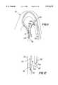
- FIG. 1is a simplified longitudinal sectional view showing a portion of an illustrative procedure and related apparatus in accordance with this invention.
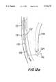
- FIG. 2is a simplified longitudinal sectional view showing a portion of a more particular illustrative procedure and related apparatus in accordance with the invention.
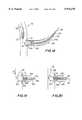
- FIG. 3is a simplified longitudinal sectional view showing an illustrative embodiment of a portion of the FIG. 2 apparatus in more detail.
- FIG. 3ais a view similar to FIG. 3 showing an alternative illustrative embodiment of the FIG. 3 apparatus.
- FIG. 4is a simplified elevational view showing an illustrative embodiment of a portion of the FIG. 3 apparatus in still more detail.
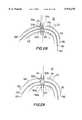
- FIG. 5is a simplified longitudinal sectional view showing another portion of an illustrative procedure and related apparatus in accordance with this invention.
- FIG. 6is a view similar to FIG. 2 showing a later stage in the illustrative procedure depicted in part by FIG. 2, together with related apparatus, all in accordance with this invention.
- FIG. 7ais a simplified longitudinal sectional view of an illustrative embodiment of a portion of the FIG. 6 apparatus in more detail.
- FIG. 7bis a simplified elevational view of a portion of the FIG. 7a apparatus, but with the depicted elements in a different physical relationship to one another.
- FIG. 7cis a simplified longitudinal sectional view of an alternative embodiment of one component of the FIG. 7a apparatus.
- FIG. 7dis a simplified longitudinal sectional view of an alternative embodiment of another component of the FIG. 7a apparatus.
- FIG. 7eis a simplified elevational view of another alternative embodiment of the component shown in FIG. 7d.
- FIG. 7fis a simplified elevational view of an alternative embodiment of still another component shown in FIG. 7a.
- FIG. 7gis a simplified elevational view of an alternative embodiment of yet another component shown in FIG. 7a.
- FIG. 8is a simplified longitudinal sectional view similar to a portion of FIG. 6 showing a still later stage in the illustrative procedure depicted in part by FIG. 6.
- FIG. 8ais a simplified sectional view of the apparatus shown in FIG. 8 without the associated tissue structure being present.
- FIG. 9is a simplified cross sectional view of an illustrative embodiment of further illustrative apparatus in accordance with this invention.
- FIG. 10is a simplified longitudinal sectional view of an illustrative embodiment of a portion of the FIG. 9 apparatus.
- FIG. 10ais a view similar to FIG. 10 showing a possible alternative construction of the FIG. 10 apparatus.
- FIG. 10bis another view similar to FIG. 10 showing another possible alternative construction of the FIG. 10 apparatus.
- FIG. 10cis another view similar to FIG. 10 showing still another possible alternative construction of the FIG. 10 apparatus.
- FIG. 11is a view similar to FIG. 6 showing an even later stage in the illustrative procedure depicted in part by FIG. 8, together with related apparatus, all in accordance with this invention.
- FIG. 12is a view similar to a portion of FIG. 11, but in somewhat more detail, showing a still later stage in the illustrative procedure depicted in part by FIG. 11.
- FIG. 12ais a view similar to FIG. 12 showing a possible alternative construction of the FIG. 12 apparatus.
- FIG. 13is a view similar to FIG. 12 showing an even later stage in the illustrative procedure depicted in part by FIG. 12.
- FIG. 14is a view similar to FIG. 11 showing a still later stage in the illustrative procedure depicted in part by FIG. 13.
- FIG. l5is a simplified longitudinal sectional view of an illustrative embodiment of a portion of still further illustrative apparatus in accordance with this invention.
- FIG. 15ais a simplified elevational view of a structure which can be used to provide part of the apparatus shown in FIG. 15.
- FIG. 15bis a view similar to FIG. 15a showing more of the structure of which FIG. 15a is a part.
- FIG. 15cis a view similar to FIG. 15b showing the FIG. 15b structure in another operational condition.
- FIG. 15dis a simplified elevational view of an alternative structure which can be used to provide part of apparatus shown in FIG. 15.
- FIG. 15eis a view similar to FIG. 15d showing the FIG. 15d structure in another operational condition.
- FIG. 15fis a simplified longitudinal sectional view of another alternative structure which can be used to provide part of the apparatus shown in FIG. 15.
- FIG. 15gis a view similar to FIG. 15f showing the FIG. 15f structure in another operational condition.
- FIG. 16is a simplified elevational view of an illustrative embodiment of one component of the FIG. 15 apparatus.
- FIG. 17is a simplified longitudinal sectional view of an illustrative embodiment of another portion of the FIG. 15 apparatus.
- FIG. 18is a view similar to a portion of FIG. 14 showing an even later stage in the illustrative procedure depicted in part by FIG. 14.
- FIG. 19is a view similar to FIG. 18 showing a still later stage in the FIG. 18 procedure.
- FIG. 20is a view similar to FIG. 19 showing an even later stage in the FIG. 19 procedure.
- FIG. 21is a view similar to another portion of FIG. 14 showing a still later stage in the FIG. 20 procedure.
- FIG. 22is a view similar to FIG. 21 showing an even later stage in the FIG. 21 procedure.
- FIG. 22ais a view similar to FIG. 22 showing a still later stage in the FIG. 22 procedure.
- FIG. 22bis a view similar to FIG. 22a showing an even later stage in the FIG. 22a procedure.
- FIG. 23is a view similar to FIG. 22b showing a still later stage in the FIG. 22b procedure.
- FIG. 24is a view similar to FIG. 23 showing an even later stage in the FIG. 23 procedure.
- FIG. 25is a simplified longitudinal sectional view of an illustrative embodiment of a portion of more apparatus in accordance with this invention.
- FIG. 26is a view similar to FIG. 20 showing a later stage in the FIG. 24 procedure.
- FIG. 27is a view similar to FIG. 26 showing a still later stage in the FIG. 26 procedure.
- FIG. 28is a view similar to FIG. 24 showing an even later stage in the FIG. 27 procedure.
- FIG. 29is a view similar to FIG. 28 showing a still later stage in the FIG. 28 procedure.
- FIG. 30is a view similar to FIG. 29 showing an even later stage in the FIG. 29 procedure.
- FIG. 31is a view similar to FIG. 14 showing the end result of the procedure depicted in part by FIG. 30.
- FIG. 32is a simplified longitudinal sectional view showing an end result similar to FIG. 31 but in a different context.
- FIG. 33is a simplified longitudinal sectional view showing a possible alternative construction of portions of the apparatus showing in FIG. 15.
- FIG. 34is a simplified elevational view (partly in section) showing another possible alternative construction of portions of the FIG. 15 apparatus.
- FIG. 35is a simplified longitudinal sectional view of the FIG. 34 apparatus in another operating condition.
- FIG. 36is a simplified elevational view of apparatus which can be used as an alternative to certain apparatus components shown in FIGS. 15 and 17.
- FIG. 37is a simplified elevational view (partly in section) showing additional components with the FIG. 36 apparatus.
- FIG. 38is a simplified longitudinal sectional view showing still another possible alternative construction of portions of the FIG. 15 apparatus.
- FIG. 39is a simplified elevational view showing in more cetail a possible construction of a portion of the FIG. 38 apparatus.
- the proceduremay begin by inserting an elongated instrument into the patient's circulatory system so that a distal portion of the instrument extends through the coronary artery narrowing to the vicinity of the point along the artery at which it is desired to make the bypass connection.
- FIG. 1which shows elongated instrument 100 entering the patient's circulatory system 10 at a remote location 12 and passing coaxially along vessels in the circulatory system until its distal end portion 104 passes through narrowing 22 in coronary artery 20 and reaches the downstream portion 24 of the artery to which it is desired to make a bypass connection.
- the entry location 12 of irnstrument 100may be a femoral (leg) artery of the patient, a brachial artery of the patient, or any other suitable entry point. It will be appreciated, however, that entry point 12 is typically remote from the location at which the bypass is to be provided, and that control of instrument 100 throughout its use is from the proximal portion 102 that is outside the patient at all times.
- FIG. 2shows a preferred embodiment of instrument 100 in more detail.
- instrument 100may include a catheter tube 110 which is inserted (from location 12 in FIG. 1) via the patient's aorta 30 to the ostium of coronary artery 20.
- Another tubular structure 120is then extended from the distal end of catheter 110, through narrowing 22 to location 24.
- tubular structure 120may have two lumens 130 and 140. Near the distal end of structure 120, lumen 130 communicates with the interior of an inflatable balloon 132 on one side of structure 120, while lumen 140 opens out to the opposite side of structure 120.
- Lumen 140contains a longitudinal structure 150 which may be a stylet wire with a sharpened distal tip 152 (see FIG. 4). (Although FIG. 4 shows indentations behind tip 152, those indentations could be eliminated if desired.)
- Structure 120may be provided with a distal spring tip 122 to help guide the distal end of structure 120 along coronary artery 20 and through narrowing 22.
- a safety ribbon 123(e.g., of the same material as tip 122) may be connected at its proximal end to the distal end of member 120 and at its distal end to the distal end of tip 122 to improve the performance of tip 122 and to help prevent separation of any portion of tip 122 from structure 120 in the event of damage to tip 122.
- Structure 120may have radiologic (e.g., radio-opaque or fluoroscopically viewable) markers 124 at suitable locations to help the physician place the structure where desired in the patient's body.
- Catheter 110may also have radiologic markers 112 for similar use.
- Balloon 132is initially deflated. Longitudinal structure 150 is initially retracted within lumen 140.
- each of components 110, 120, and 150is separately controllable from outside the patient, generally indicated as region 102 in FIG. 1.
- balloon 132may be provided on another longitudinal structure 120' (FIG. 3a) which is substantially parallel to the remaining components described above for structure 120.
- Structure 120'may be substantially separate from structure 120, or it may be attached to structure 120.
- a second elongated instrument 200is similarly introduced into the patient's circulatory system 10 as shown generally in FIG. 5.
- instrument 200may enter the patient (at 14) via a femoral artery, a brachial artery, or any other suitable location, which again is typically remote from the bypass site. If one femoral artery is used to receive instrument 100, the other femoral artery may be used to receive instrument 200. Or the same femoral artery may be used to receive both instruments. Or any other combination of entry points may be used for the two instruments.
- Instrument 200is inserted until its distal end is adjacent to the point 34 in the circulatory system which it is desired to connect to point 24 via a bypass.
- FIG. 6shows a more specific example in FIG. 6 where the distal end of instrument 200 is shown at location 34 in aorta 30.
- the particular location 34 chosen in FIG. 6is only illustrative, and any other location along aorta 30 may be selected instead.
- Radiologic markers 206may be provided on the distal portion of instrument 200 to help the physician position the instrument where desired. Note that FIG. 6 shows portions of instruments 100 and 200 side by side in aorta 30.
- FIG. 7aAn illustrative construction of instrument 200 is shown in more detail in FIG. 7a.
- This FIG.shows the distal portions of elements 220, 230, 240, and 250 telescoped out from one another and from the distal end of outer member 210 for greater clarity. It will be understood, however, that all of these elements are initially inside of one another and inside outer member 210. Indeed, member 210 may be initially positioned in the patient without any or all of elements 220, 230, 240, and 250 inside, and these elements may then be inserted into member 210. Moreover, the number of members like 220, 230, etc., may be more or less than the number shown in FIG. 7a, depending on the requirements of a particular procedure.
- Outer member 210may be a catheter-type member.
- the distal portion of catheter 210may carry two axially spaced annular balloons 212 and 214.
- Proximal balloon 212is inflatable and deflatable via inflation lumen 216 in catheter 210.
- Distal balloon 214is inflatable and deflatable via inflation lumen 218 in catheter 210.
- Lumens 216 and 218are separate from once another so that balloons 212 and 214 can be separately controlled.
- Balloons 212 and 214are shown substantially deflated in FIG. 7a.
- the distal end of catheter 210may be tapered as shown at 211 in FIG. 7c to facilitate passage of catheter 210 through an aperture in aorta 30 as will be described below.
- Sheath 220is longitudinally movable relative to catheter 210.
- the distal portion of sheath 220may be tapered as shown at 222 in FIG. 7d, and/or externally threaded as shown at 224 in FIG. 7e.
- Either or both of features 222 and 224may be provided to facilitate passage of sheath 220 through an aperture in aorta 30 as will be described below. If threads 224 are provided, then sheath 220 is rotatable (either alone or with other components) about the longitudinal axis of instrument 200 in order to enable threads 224 to engage the tissue of the aorta wall and help pull sheath 220 through the aorta wall.
- Tube 230is longitudinally movable relative to sheath 220.
- Tube 230may also be rotatable (about the central longitudinal axis of instrument 200) relative to sheath 220, and the distal end of tube 230 may be threaded on the outside (as shown at 232 in FIG. 7f) for reasons similar to those for which threading 224 may be provided on sheath 220.
- Tube 230is preferably controllable from its proximal portion (outside the patient) to deflect laterally by a desired amount to help steer, push, or twist instrument 200 to the desired location in the patient.
- Tube 240Coaxially inside tube 230 is tube 240.
- Tube 240is longitudinally movable relative to tube 230, and may be metal (e.g., stainless steel) hypotube, for example.
- Screw head 242is mounted on the distal end of tube 240 and is threaded (as indicated at 244) on its distal conical surface.
- Tube 240is rotatable (about the central longitudinal axis of instrument 200, either alone or with other elements) in order rotate head 242 and thereby use threads 244 in engagement with the tissue of the aorta wall to help pull head 242 through that wall as will be more fully described below. Because tube 240 is hollow, it can he used for passage of fluid or pressure into or out of the patient.
- longitudinal structure 250Coaxially inside tube 240 is longitudinal structure 250.
- Longitudinal structure 250is longitudinally movable relative to tube 240.
- Structure 250may also be rotatable (about its longitudinal axis) relative to tube 240 and/or other elements.
- Structure 250may be a wire with a distal end portion 252 that is resiliently biased to deflect laterally to one side. Wire portion 252 is kept relatively straight when it is inside tube 240 as shown in FIG. 7a. But when wire portion 252 is pushed axially out the distal end of tube 240, it curves to one side as shown in FIG. 7b.
- the distal portion of structure 250may be threaded as shown at 254 in FIG. 7g to help structure 250 thread its way through the wall of aorta 30.
- All of components 210, 220, 230, 240, and 250are controlled from outside the patient's body (i.e., from region 202 in FIG. 5).
- proximal balloon 212When the distal portion of catheter 210 is at the desired location 34, proximal balloon 212 is inflated. Even when inflated, proximal balloon 212 is not large enough to block aorta 30.
- wire 250is pushed distally so that its distal portion emerges from the distal end of tube 240 and penetrates the wall of aorta 30 at location 34. This anchors the distal portion of instrument 200 to the aorta wall at the desired location. Because of its operation to thus anchor instrument 200, wire 250 is sometimes referred to as an anchor wire.
- the rotatability of wire 250, as well as its resilient lateral deflection (FIG. 7b) and/or threads 254 (FIG. 7g),may be used to help get the distal end of the wire to the desired location 34 and firmly into the aorta wall at that location in order to achieve the desired anchoring of instrument 200.
- tubes 230 and 240are moved in the distal direction relative to wire 250 so that screw head 242 begins to follow wire 250 into and through the aorta wall.
- at least tube 240is rotated about its longitudinal axis so that threads 244 help to pull head 242 into and through the aorta wall.
- the distal portion of tube 230follows head 242 through the aorta wall. If provided, threads 232 and rotation of tube 230 may facilitate transfer of the aorta wall tissue from head 242 to tube 230.
- sheath 220When tube 230 is through the aorta wall, sheath 220 is moved distally relative to tube 230 so that a distal portion of sheath 220 follows tube 230 through the aorta wall. If provided, the distal taper 222 and/or threads 224 and rotation of sheath 220 help the distal portion of sheath 220 through the aorta wall. Then catheter 210 is advanced distally relative to sheath 220 so that a distal portion of catheter 210 follows sheath 220 through the aorta wall. Again, the distal taper 211 of catheter 210 (if provided) helps the distal portior of the catheter through the aorta wall. Inflated proximal balloon 212 prevents more than just the portion of catheter 210 that is distal of balloon 212 front passing through the aorta wall.
- the previously extended elementscan be and preferably are either held stationary or pulled back proximally to prevent them from damaging body tissues outside the aorta.
- distal balloon 214When the distal portion of catheter 210 is through the aorta wall, distal balloon 214, which is now outside the aorta, is also inflated.
- the axial spacing between balloons 212 and 214is preferably small enough so that the aorta wall is clamped between these two balloons as shown in FIG. 8.
- balloons 212 and 214were inflated without the presence of the aorta wall, their appearance might be as shown in FIG. 8a.
- the close spacing of balloons 212 and 214, as well as their resilient bias toward one another,helps to anchor catheter 210 through the aorta wall and also to seal the aorta wall around the catheter.
- Balloons 212 and 214may be inflated by liquid or gas, and they may be specially coated to help improve the seal between catheter 210 and the aorta wall.
- snare 300includes one or more sheath structures such as 310a and 310b that are operable by the physician to steer the snare by curvilinearly deflecting it laterally by a desired, variable amount.
- a fiber optic bundle 320for conveying light from outside the patient to the distal end of snare 300 in order to provide illumination beyond the distal end of the snare
- another fiber optic bundle 330for conveying an image from beyond the distal end of the snare back to optical and/or video equipment outside the patient and usable by the physician to see what is beyond the distal end of the snare
- Additional lumenssuch as 360 may be provided for such purposes as introducing fluid that may help to clear the distal ends of fiber optic bundles 320 and 330, for introducing fluid for irrigating and/or medicating the patient, for suctioning fluid from the patient, etc. It may not be necessary to provide a separate snare sheath 340, but rather element 340 may merely be a lumen through the general structure 300 for snare instrument 350.
- instrument 350includes a wire 352 with a snare loop 354 (also of wire) at its distal end. Loop 354 is closed when it is inside snare sheath or lumen 340. Loop 354 opens resiliently to the shape shown in FIG. 10 when it extends distally beyond the distal end of sheath or lumen 340.
- snare loop 354is mounted on the distal end of a fiber optic bundle 352'.
- Fiber optic bundle 352'may perform the functions described above for bundle 320 or bundle 330, thereby integrating those functions into instrument portion 350.
- snare loop 354is mounted on the distal end of a tube 352", which can be used to deliver other types of instrumentation to the vicinity of snare loop 354.
- tube 352"may be metal (e.g., stainless steel) hypotube, and the other instrumentation delivered via that tube may be a tissue cutter for use in cooperation with snare loop 354 to perform a biopsy.
- snare loop 354is part of one continuous length of wire 352a.
- a possible advantage of the embodiment shown in FIG. 10cis that it permits snare loop 354 to be variable in size, determined by how much of wire 352a is extended from the distal end of lumen 340.
- the distal portion of steerable endoscopic snare 300is extended distally beyond the distal end of catheter 210 and steered by the physician until it is adjacent to the exterior of coronary artery portion 24.
- the next step in the illustrative procedure being describedis preferably to deploy snare loop 354 by extending it distally from the distal end of structure 300 as shown in FIG. 12. Alternatively, this step could be performed somewhat later.
- the next stepis to inflate balloon 132 to push tube 120 against the opposite side wall of coronary artery 20 at location 24.
- stylet wire 150is moved in the distal direction as shown in FIG. 12 so that its distal tip 152 passes through the wall of the coronary artery.
- the distal end of the stylet wire lumen in tube 120is shaped to help guide stylet wire 150 through the coronary artery wall.
- balloon 132can be deflated.
- Balloon 132may be a perfusion balloon which allows continued blood flow along artery 20 even while the balloon is inflated.
- FIG. 12ashows an alternative embodiment in which a perfusion balloon 132' is provided on tube 120 proximally of the outlet for wire 150.
- Balloon 132'is inflated when it is desired to stabilize the location of tube 120 in coronary artery 20 (e.g., while the distal portion of wire 150 is being pushed out through the coronary artery wall).
- a balloon like 132'is near the distal end of a balloon catheter from which tube 120 extends distally.
- Still another possibilitymay be to omit balloons like 132 and 132' entirely. If a balloon 132 or 132' is provided, it may not be necessary for it to be a perfusion balloon.
- the next stepis to ensure that the distal portion of the wire passes through snare loop 354 as shown in FIG. 12 or FIG. 12a. This may be facilitated by continued use of the visual observation and steering capabilities of snare 300.
- An especially preferred techniqueis to deploy snare loop 354 so that it is next to coronary artery section 24. Then when stylet wire 150 emerges from the coronary artery at 24, it immediately passes through snare loop 354 with no further manipulation being required.
- snare sheath or lumen 340is moved distally relative to the snare loop. This causes snare loop 354 to close down on wire 150. Snare sheath or lumen 340 also tends to trap the distal portion of wire 150 and to fold that wire portion back on itself inside sheath or lumen 340 as shown in FIG. 13.
- steerable endoscopic snare 300may be withdrawn from the patient by pulling it proximally out of catheter 210.
- the condition of the apparatus inside the patientis now as shown in FIG. 14. Note that the resence of fixed outlets for the wire from the distal ortion of tube 120 and the distal end of catheter 210 prevents wire 150 from cutting tissues 20 and 30 when the wire is pulled in either longitudinal direction.
- the portion of whre 150 extending through the interior of the patient between elements 120 and 210may have radiologic markers 154 equally spaced along its length. These can be viewed radiologically by the physician to determine the distance between regions 24 and 34 via wire 150. This helps the physician select the correct length of graft needed between regions 24 and 34.
- the next phase of the illustrative procedure being describedis to install a new length of tubing between regions 24 and 34.
- the new length of tubingmay be either an artificial graft, natural body organ tubing harvested from the patient's body, or a combination of artificial and natural tubing (e.g., natural tubing coaxially inside artificial tubing).
- the new tubingis to be natural tubing (e.g., a length of the patient's saphenous vein that has been harvested for this purpose) inside an artificial conduit.
- both conduitscan be delivered and installed simultaneously, Dr the outer artificial conduit can be delivered and installed first, and then the inner natural conduit can be delivered and installed.
- the latter techniqueis employed.
- the next step in the procedureis to use catheter 210 and wire 150 to deliver an artificial conduit so that it extends between regions 24 and 34.
- the distal portion of an illustrative assembly 400 for doing thisis shown in FIG. 15. (Several alternative constructions of this portion of the apparatus are shown in later FIGS. and described below.)
- assembly 400includes a threaded, conical, distal tip 412 mounted on a tubular member 410 (e.g., metal hypotube) through which wire 150 can freely pass. Additional details regarding various possible constructions of tip 412 are provided later with reference to FIGS. 15a-15g, but it should be mentioned here that in this embodiment tip 412 is selectively collapsible to facilitate its withdrawal from the patient after it has served its purpose.
- a tubular member 420is disposed concentrically around tubular member 410.
- An inflatable balloon 422is mounted on the distal end of tubular member 420.
- Tubular member 420includes an axially extending lumen (not shown in FIS. 15) for use in selectively inflating and deflating balloon 422. Balloon 422 is shown deflated in FIG. 15.
- an artificial graft conduit 430Coaxially around tubular member 420 is an artificial graft conduit 430.
- An illustrative embodiment of a suitable conduit 430is shown in FIG. 16 and inclades a tube formed of a frame 432 of a first highly elastic material (such as nitinol) with a covering 434 of a second highly elastic material (e.g., a rubber-like material such as silicone) substantially filling the apertures in the frame.
- a first highly elastic materialsuch as nitinol
- a second highly elastic materiale.g., a rubber-like material such as silicone
- barbs 436 and flaps 438are compressed radially inwardly and confined within conduit delivery tube 440, which c,oaxially surrounds conduit 430.
- conduit 430may be somewhat circumferentially compressed by tube 440.
- FIG. 17The portion of assembly 440 at which the proximal end of conduit 430 is located is shown in FIG. 17. There it will be seen how flaps 438 are confined within conduit delivery tube 440. FIG. 17 also shows how tubes 410, 420, and 440 extend proximally (to the right as viewed in FIG. 17) from the proximal end of conduit 430 so that the physician can remotely control the distal portion of assembly 400 from outside the patient.
- assembly 400is fed into the patient along wire 150 through catheter 210.
- tip 412reaches coronary artery portion 24, tip 412 is threaded into and through the coronary artery wall by rotating tube 410 and therefore tip 412. (Tube 120 may be pulled back slightly at this time to make sure that it does not obstruct tip 412.)
- the passage of tip 412 through the coronary artery wallopens up the aperture in that wall. After tip 412 passes through thIe artery wall, that wall seals itself against the outside of the distal portion of conduit delivery tube 440D as shown in FIG. 18.
- Conduit 430is initially moved distally with components 410 and 412. This may be done by inflating balloon 422 so that it engages conduit 430, and then moving tube 420 distally with components 410 and 412. Distal motion of conduit 430 moves barbs 436 beyond the distal end of delivery tube 440, thereby allowing the barbs to spring out inside coronary artery 20 as shown in FIG. 19. This prevents the distal end of conduit 430 from being pulled proximally out of the coronary artery. If balloon 422 was inflated during this phase of the procedure, it may be deflated before beginning the next phase.
- the next stepis to pull delivery tube 440 back slightly so that it is withdrawn from coronary artery 20. Then tube 420 is moved distally so that balloon 422 is radially inside the annulus of barbs 436. Balloon 442 is then inflated to ensure that barbs 436 are firmly set in coronary artery 20. Conditions are now as shown in FIG. 20. Cross sections of balloon 422 may be L-shaped when inflated (one leg of the L extending parallel to the longitudinal axis of conduit 430, and the other leg of the L extending radially outward from that longitudinal axis immediately distal of barbs 436). This may further help to ensure that barbs 436 fully engage the wall of coronary artery 20.
- the next stepis to deflate balloon 422.
- delivery tube 440is withdrawn proximally until flap 438a (but not flap 438b) is distal of the distal end of the delivery tube. This allows flap 438a to spring radially out as shown in FIG. 21.
- Tube 420is then withdrawn until balloon 422 is just distal of flap 438a. Then balloon 422 is inflated, producing the condition shown in FIG. 21.
- next stepsare (1) to deflate distal balloon 214, (2) to proximally withdraw catheter 210 a short way, (3) tD proximally withdraw tube 420 to press flap 438a against the outer surface of the aorta wall, and (4) to proximally withdraw delivery tube 440 by the amount required to allow flap 438b to spring out against the interior of catheter 210, all as shown in FIG. 22.
- the barbs 439 on flap 438aare urged to enter the aorta wall tissue to help maintain engagement between flap 438a and the wall of the aorta.
- Inflated balloon 422helps to set barbs 439 in the tissue when tube 420 is tugged proximally.
- the next stepis to insert the distal portion of delivery tube 440 into the proximal end of conduit 430 as shown in FIG. 22a.
- the distal end of conduit 430may be inserted all the way to the proximal end of balloon 422 (see FIG. 23 for a depiction of this).
- a purpose of this stepis to subsequently help control the rate at which blood is allowed to begin to flow through conduit 430.
- the next stepis to proximally withdraw catheter 210 by the amount required to release flap 438b to spring out against the interior of the wall of aorta 30 as shown in FIG. 22b.
- Catheter 210may be subsequently pushed back against flap 438b as shown in FIG. 23 to help securely engage that flap against the aorta wall.
- FIGS. 15a-15gSeveral illustrative embodiments of collapsible tips 412 are shown in FIGS. 15a-15g.
- a frame of wire struts 412aextends radially out and proximally back from the distal end of hypotube 410 (see especially FIG. 15a).
- This frameis covered with a somewhat elastic polymer cover 412b (FIG. 15b) which is provided with threads as indicated at 412c.
- threads 412cmay be made of one or more spirals of nitinol wire or other metal.
- another hypotube 410a(which is disposed around hypotube 410) is shifted distally relative to hypotube 410 to invert and collapse tip 412 as shown in FIG. 15c.
- tip 412has a central main portion 412e attached to hypotube 410.
- main portion 412eAround the proximal portion of main portion 412e are a plurality of triangular shaped portions 412f, each of which is connected to main portion 412e by a hinge 412g.
- the outer surface of the tipis threaded as indicated at 412h.
- tip 412may be made of a plastic polymer material, and hinges 412g may be so-called "living" hinges between the various masses of the polymer.
- triangular portions 412fmeet any resistance as tip 412 is withdrawn proximally, they pivot about their hinges 412g to the positions shown in FIG. 15e, thereby greatly reducing the circumferential size of the tip.
- metal struts 412jare attached to the distal end of hypotube 410 so that they extend radially out and proximally back.
- struts 412jare covered with a cover and thread, like the cover 412b and threads 412c shown in FIG. 15b and described above.
- a wire 412kconnects a proximal portion of each strut 412j, through an aperture in hypotube 410, to the distal end of another hypotube 410b which is disposed inside hypotube 410. When wires 412k are relaxed as shown in FIG.
- struts 412jextend radially out beyond the circumference of delivery tube 440.
- hypotube 410bis pulled back proximally relative to hypotube 410 as shown in FIG. 15g. This causes wires 412k to pull struts 412j in so that the outer circumference of tip 412 is much smaller than the circumference of delivery tube 440.
- natural body conduite.g. a Length of the patient's saphenous vein that has been harvested for this purpose
- artificial conduit 430An illustrative assembly 500 for delivering a length of natural body conduit to installed conduit 430 is shown in FIG. 25.
- assembly 500includes a tube 510 disposed around wire 150 so that tube 510 is freely movable in either direction along wire 150.
- Tube 510has an inflatable annular balloon 512a near its distal end and another inflatable annular balloon 512b spaced in the proximal direction from balloon 512a.
- Tube 510includes separate inflation lumens (not shown) for each of balloons 512 so that the balloons can be separately inflated and deflated.
- An annular collar structure or ring 520ais disposed concentrically around balloon 512a, and a similar annular collar structure or ring 520b is disposed concentrically around balloon 512b.
- Balloons 512may be partly inflated.
- Each of rings 520may have radially outwardly extending barbs 522.
- a length of natural body conduit 530(e.g., saphenous vein as mentioned earlier) extends from ring 520a to ring 520b around the intervening portion of tube 510. Barbs 522 may extend through the portions of conduit 530 that axially overlap rings 520.
- a delivery tube 540is disposed around conduit 530. In use, tubes 510 and 540 extend proximally (to the right as viewed in FIG. 25) out of the patient to permit the physician to remotely control the distal portion of assembly 500.
- assembly 500may include a spring coil (similar to coil 450 in FIG. 36) extending between rings 520 inside of conduit 530 to help hold conduit 530 open and out against delivery tube 54) or subsequently out against conduit 430.
- balloons 512may be both in the same tube 510, balloon 512a may be on a relatively small first tube, while balloon 512b is on a larger second tube that concentrically surrounds the proximal portion of the first tube.
- the first and second tubesare axially movable relative to one another, thereby allowing the distance between balloons 512 to be adjusted for grafts 530 of different lengths.
- Assembly 500is employed by placing it on wire 150 leading into catheter 210. Assembly 500 is then advanced distally along wire 150 through catheter 210 and then into conduit 430 until the distal end of conduit 530 is adjacent the distal end of conduit 430 and the proximal end of conduit 530 is adjacent the proximal end of conduit 430.
- the condition of the apparatus at the distal end of assembly 500is row as shown in FIG. 26.
- the condition of the apparatus at the proximal end of conduit 530is as shown in FIG. 28.
- the next stepis to proximally withdraw delivery tube 540 so that the distal portion of conduit 530 and distal barbed ring 520a are no longer inside the distal portion of delivery tube 540.
- distal balloon 512ais inflated to circumferentially expand ring 520a and to set barbs 522 through conduit 530 into the surrounding portion of conduit 430 and coronary artery wall portion 24.
- FIG. 27shows the condition of the apparatus at this stage in the procedure.
- the next stepis to continue to proximally withdraw delivery tube 540 until the proximal end of conduit 530 and proximal ring 520b are no longer inside tube 540 (see FIG. 29). Then proximal balloon 512b is inflated to circumferentially expand ring 520b and thereby set barbs 522 through conduit 530 into the surrounding portion of conduit 430 and aorta wall portion 34 (see FIG. 30). This provides a completed anastomosis of the proximal end of conduit 530 to aorta 30.
- the next stepis to deflate balloons 512a and 512b and proximally withdraw tube 510 and delivery tube 540 from the patient via catheter 210.
- wire 150is withdrawn from the patient, either by pulling it proximally from catheter 210 or by pulling it proximally from elements 110 and 120.
- elements 110, 120, and 210are all proximally withdrawn from the patient to conclude the procedure.
- the bypass that is left in the patientis as shown in FIG. 31. This bypass extends from aorta 30 at location 34 to coronary artery 20 at location 24.
- the bypassincludes natural body conduit 530 inside artificial graft conduit 430.
- bypassOne end of the bypass is anchored and anastomosed to coronary artery 20 by barbs 436 and ring 520a.
- the Dther end of the bypassis anchored and anastomosed to aDrta 30 by flaps 438 and ring 520b.
- bypass 620is a same-vessel bypass around a narrowing 612 in vessel 610.
- the various components of bypass 620are identified using the same reference numbers that are used for similar elements in FIG. 31.
- the inventionis also applicable to procedures similar to any of those mentioned above, but for non-circulatory systems such as urological tubing.
- FIGS. 15-15gare illustrative of only one of several possible approaches to providing a structure that can penetrate the wall of coronary artery 20 from outside the artery.
- FIG. 33Another example of a suitable structure is shown in FIG. 33.
- FIG. 33uses reference numbers with primes for elements that are generally similar to elements identified by the corresponding unprimed reference numbers in FIG. 15.
- distal tip 412'has external threads 414 for helping to grip and dilate tissue such as the wall of coronary artery 20 as tip 412' is rotated about wire 150 by rotation of proximally extending tubular shaft 410'.
- Threads 414continue as threads 442 on the exterior of the distal portion of tube 440'.
- Threads 414also threadedly engage with threads 444 on the interior of the distal portion of tube 440'.
- structure 410'can be removed from structure 440' by rotating structure 410' in the direction relative to structure 440' that causes threads 414 and 444 to cooperate to shift tip 412' proximally relative to structure 440'.
- elements 410' and 412'can be pulled proximally out of the patient.
- Tube 440'which remains in place through the coronary artery wall, can thereafter be used as a guide tube for delivery of a graft structure (such as 430 (FIGS. 15-17)) and associated instrumentation (such as structure 420 (e.g., FIGS. 15 and 17)) to the operative site.
- FIGS. 34 and 35Another illustrative alternative embodiment of some of the instrumentation shown in FIG. 15 is shown in FIGS. 34 and 35.
- FIGS. 34 and 35use reference numbers with primes for elements that are generally similar to elements identified by the corresponding unprimed reference numbers in FIG. 15.
- barbs 436'are connected to the distal end of a serpentine ring 439 which is connected in turn to the distal end of frame 432'.
- Barbs 436'are initially held in the form of a distally pointed cone by yieldable bands 437a, 437b, 437c, and 437d.
- bands 437may be made of a polymeric or other suitable yieldable material. Alternatively, bands 437 could be serpentine metal members that yield by becoming straighter. Bards 437 are initially strong enough to prevent barbs 436' from flaring radially outward from conduit 430' as the barbs are resiliently biased to do. However, bands 437 can be made to yield by inflating balloon 422' (on the distal end of tube 420') inside the annulus of barbs 436'.
- Barbs 436'can be forced through tissue such as the wall of coronary artery 20 in their initial cone shape. Sufficient pushing force can be applied to the cone of barbs 436' in any of several ways.
- tube 420'may be metal (e.g., stainless steel) hypotube which can transmit pushing force to the cone of barbs 436' by inflating balloon 422' to trap the base of the cone between balloon 422' and tube 440. Additional pushinag force may then also be applied via tube 440 itself.
- bands 437may be made progressively weaker in the distal direction to facilitate prompt yielding of distal bands such as 437a and 437b in response to relatively little inflation of balloon 422', whereas more proximal bands such as 437c and 437d do not yield until somewhat later in response to greater inflation of balloon 422'. This progression of yielding may help ensure that the annulus of barbs flares out in the desired trumpet-bell shape inside the coronary artery.
- FIGS. 36 and 37illustrate another possible use of a cone structure like that shown in FIGS. 34 and 35, as well as illustrating other possible aspects of the invention.
- FIGS.illustrate a structure that can be used to deliver an artificial graft conduit, or a natural graft conduit, or both an artificial graft conduit and a natural graft conduit simultaneously (e.g., with the natural conduit coaxially inside the artificial conduit).
- FIGS. 36 and 37it is assumed that only natural graft conduit is being delivered, but it will be readily apparent that artificial graft conduit could be substituted for or added outside the natural graft conduit.
- the cone of barbs 436'is mounted on the distal end of a highly elastic coil spring 450.
- the proximal end of coil 450is attached to ring 460.
- the cone of barbs 436'is provided with additional, relatively short, radially outwardly projecting barbs 436" near the proximal base of the cone.
- barbs 436"extend into and/or through the distal portion of a length of graft tubing 530, which (as has been mentioned) is assumed in this case to be natural body organ tubing such as saphenous vein.
- Ring 460is similarly provided with radially outwardly extending barbs 462 which extend into and/or through the proximal portion of graft conduit 530. Ring 460 also includes resilient radially outwardly extending annular flaps 438a and 438b with barbs 439, all similar to correspondingly numbered elements in FIG. 16.
- Spring 450which is inside conduit 530 between the cone of barbs 436' and ring 460, helps to support and hold open the graft conduit.
- Structure 420'(similar to structure 420' in FIGS. 34 and 35 and including balloon 422' as shown in those FIGS.) is disposed around wire 150 inside structures 436', 450, 460, and 530. Delivery tube 440 is disposed around conduit 530.
- FIGS. 36 and 37illustrates a structure which can be used to deliver and install natural body organ conduit without any full length artificial graft conduit being used.
- the structure shown in FIG. 37is delivered to the operative site via wire 150.
- the cone of barbs 436'is forced through the wall of coronary artery 20 and then flared radially outward inside the coronary artery to anchor the distal end of the graft conduit to that artery.
- the distal end of delivery tube 440is pulled back as needed to aid in attachment of the distal end of the graft structure. Attachment of the proximal end of the graft structure to the wall of aorta 30 is performed similarly to what is shown in FIGS.
- coil 450is optional. If coil 450 is used, its ends may or may not be attached to structures 436 and/or 460.
- a coil like coil 450can be used in other embodiments of the invention.
- a coil like 450could be used between rings 520a and 520b in embodiments like that shown in FIG. 25 to help hold open graft conduit 530 in that embodiment.
- FIG. 38uses reference numbers with double primes for elements that are generally similar to elements identified by the corresponding unprimed reference numbers in FIG. 15.
- the distal end of artificial graft conduit 430"is attached to expandable ring 430a.
- Elongated barbs 436"extend distally from the distal end of ring 430a. The distal ends of barbs 436" are turned back in the proximal direction and extend just far enough into the distal end of tube 420" to be releasably retained by that tube.
- Barbs 436"are resiliently biased to extend radially outward from ring 430a, but are initially restrained from doing so by the presence of their distal end portions in the distal end of tube 420". Thus barbs 436" initially form a distally pointing cone that can be pushed through tissue such as the wall of coronary artery 20 in the same manner that has been described above in connection with FIGS. 34-37.
- Structure 420which may be metal (e.g., stainless steel) hypotube with an inflatable annular balloon 422" near its distal end, may be used to help push the cone through the tissue.
- each of barbs 436"may he twisted 180° as shown in FIG. 39 before it enters the distal end of tube 420". This promotes turning of the extreme distal end portions of the barbs toward the coronary artery wall when the barbs are released from tube 420".
- Ring 430a and barbs 436"may be made of any suitable material such as any 300-series stainless steel (e.g., 316L stainless steel). Another material that may be suitable for barbs 436" is nitinol. As in previously described embodiments, the elastic cover 434 that forms part of conduit 430" preferably extends to regions 430a and 436".
- a preferred artificial graftin accordance with this invention includes an open frame structure (such as 432 in FIG. 16).
- This frame structuremay have any desired shape such as a tube, a flat or contoured sheet, etc.
- the frame structuremay be formed in any suitable way such as by cutting apertures in an initially imperforate structure; forming a mesh of strands of frame material; braiding, knitting, weaving, or felting together strands of frame material; etc.
- the frame materialis preferably an elastic material.
- Preferred materialsare metal, although polymeric materials may also be used.
- the presently most preferred materialis nitinol, and the presently most preferred structure for the frame of a tubular graft is a braid of nitinol wires.
- the above-described graft frameis preferably covered with a covering of elastic rubber-like material which substantially fills the apertures in the frame as at 434 in FIG. 16.
- the coveringmay be inside the frame structure, outside the frame structure, or both inside and outside the frame structure.
- Preferred rubber-like materials for the coveringare polymeric materials, especially polymeric rubber materials.
- the presently most preferred rubber-like materialis silicone.
- Examples of other suitable rubber-like materialsare stretchable urethane, stretchable PTFE, natural rubber, and the like.
- the coveringcan be made either porous or non-porous as desired.
- the graft structuremay include one or more coatings over the above-described covering.
- the coating(s)may be inside the tube, outside the tube, or both inside and outside the tube.
- Possible coating materialsinclude bio-compatible materials and/or drugs. Examples include hydrophylic polymers such as hydrophylic polyurethane (to create a lubricious surface), parylene (a polymer commonly used to coat pacemakers), PTFE (which may be deposited from a PTFE vapor using a process that is sometimes called vapor transport), the drug Heparin (a common anti-coagulant), collagen, human cell seeding, etc.
- One purpose of such a coatingmay be to give the coated surface a very high degree of bio-compatibility and/or a very hicgh degree of smoothness.
- the graft structuremay or not include hooks, barbs, flaps, or other similar structures for such purposes as helping to anchor the graft in the body, provide anastomoses between the graft and existing body tubing, etc.
- hooks, barbs, flaps, and the likemay be extensions of the frame structure or may be molded with or otherwise added to the frame or covering.
- the most preferred grafts of this inventionare highly elastic.
- the elastic nature of these graft structuresallows them to be deployed less invasively (e.g., intravascularly or at least percutaneously). This avoids or reduces the need for surgical implantation.
- a tubular graft of this constructioncan be stretched to several times its relaxed length, which greatly reduces its diameter. This facilitates intravascular delivery of the graft. When released from the delivery apparatus, the graft automatically returns to its relaxed length and diameter, with no ill-effects of any kind from its previous deformation.
- the graftis so flexible and elastic that it pulsates in response to pressure waves or pulses in the blood flow. This distensibility of the graft may help prevent blood clots. Coatings that are used on the graft are preferably similarly distensible.
- the preferred wire diameteris in the range from about 0.0005 to about 0.01 inches.
- An especially preferred wire diameteris about 0.002 inches.
- the preferred silicore covering thicknessis in the range from about 0.00025 to about 0.1 inches.
- Two covering layersmay be used: one inside and one outside the frame structure. If the covering is made porous, the preferred pore size is in the range from about 1 to about 500 microns. An especially preferred pore size is about 30 microns.
- the preferred covering porosityis in the range from about 50% to about 95%. In other words, from about 50% to about 95% of the volume of the covering is pore space. If any coatings are applied to the graft, they are preferably thinner than the covering.
- a preferred manufacturing process in accordance with the inventionincludes placing or forming the frame structure of the graft on a form (e.g., a rod-like mandrel or tube in the case of the frame for a tubular graft).
- the forme.g., mandrel
- the coveringis then applied to the frame or the form.
- the coveringis cured, and the frame and covering are removed from the form. Any release agent that remains on the graft is removed.
- the release agentis polyvinyl alcohol, it may be removed by boiling the graft in water.
- a layer of the covering materialmay be applied to the form before the frame structure is placed or formed on the form.
- the formmay be provided with a very smooth surface to give the finished graft a correspondingly smooth surface.
- a very smooth mandrelmay be used to give the inside of a tubular graft a very smooth surface.
- the coatingmay be done at any suitable time.
- the coatingmay be done after the graft has been removed from the form.
- the coating or coatingsmay be applied using any suitable technique such as dipping, electrostatic spraying, vapor transport, in vitro cell reproduction, etc.
- a preferred method in accordance with the invention for making the graft covering porousis to mix particles of another material with the covering material before applying the covering material to the frame.
- the particulate materialis selected as one which is stable or at least relatively stable during curing of the covering on the frame, but which can then be removed from the cured covering to leave the covering with the desired porosity.
- the particulate materialmay be a salt such as ammonium carbonate, which is relatively stable at temperatures substantially below about 78° C., but which vaporizes relatively rapidly at an elevated temperature (i.e., about 78° C.) that is not harmful to the cured coating material.
- Any other particulate material that can be removed by vaporization or solutioncan be used.
- the particulate materialmay be removed by dissolving in water or another solvent, by exposure to air or another vaporization medium, by heat, by vacuum, or by any other suitable means.
- Porosity of the coveringis believed to be beneficial for circulatory system grafts. It may promote growth of a cell structure on the inside wall of the graft. And in all uses, porosity may promote better adherence of the above-mentioned coatings to the graft.
- radiologic elements and techniquesare used for observation of the apparatus inside the patient may vary.
- radiologic fluidsmay be injected into the patient through various lumens in the apparatus to help monitor the location of various apparatus components in the patient, and/or radiologic markers (of which the above-described markers such as 112, 124, and 154 are examples) may be provided anywhere on the apparatus that may be helpful to the physician.
Landscapes
- Health & Medical Sciences (AREA)
- Life Sciences & Earth Sciences (AREA)
- Engineering & Computer Science (AREA)
- Biomedical Technology (AREA)
- Veterinary Medicine (AREA)
- Public Health (AREA)
- General Health & Medical Sciences (AREA)
- Animal Behavior & Ethology (AREA)
- Heart & Thoracic Surgery (AREA)
- Pulmonology (AREA)
- Surgery (AREA)
- Vascular Medicine (AREA)
- Oral & Maxillofacial Surgery (AREA)
- Transplantation (AREA)
- Biophysics (AREA)
- Cardiology (AREA)
- Anesthesiology (AREA)
- Hematology (AREA)
- Medical Informatics (AREA)
- Molecular Biology (AREA)
- Gastroenterology & Hepatology (AREA)
- Nuclear Medicine, Radiotherapy & Molecular Imaging (AREA)
- Optics & Photonics (AREA)
- Physics & Mathematics (AREA)
- Pathology (AREA)
- Radiology & Medical Imaging (AREA)
- Mechanical Engineering (AREA)
- Orthopedic Medicine & Surgery (AREA)
- Prostheses (AREA)
- Infusion, Injection, And Reservoir Apparatuses (AREA)
- Graft Or Block Polymers (AREA)
- Materials For Medical Uses (AREA)
- Surgical Instruments (AREA)
- Electrotherapy Devices (AREA)
Abstract
Description
Claims (40)
Priority Applications (42)
| Application Number | Priority Date | Filing Date | Title |
|---|---|---|---|
| US08/745,618US5976178A (en) | 1996-11-07 | 1996-11-07 | Medical grafting methods |
| US08/839,298US5931842A (en) | 1996-11-07 | 1997-04-17 | Methods and apparatus for handling tubing used in medical procedures |
| DE69734244TDE69734244T2 (en) | 1996-11-07 | 1997-11-05 | DEVICE FOR INTRODUCING A MEDICAL TRANSPLANT |
| AU51057/98AAU5105798A (en) | 1996-11-07 | 1997-11-05 | Medical grafting methods and apparatus |
| EP97945582AEP0951251B1 (en) | 1996-11-07 | 1997-11-05 | Medical grafting connectors |
| PCT/US1997/020846WO1998019635A1 (en) | 1996-11-07 | 1997-11-05 | Methods and apparatus for handling tubing used in medical procedures |
| PCT/US1997/020244WO1998019634A2 (en) | 1996-11-07 | 1997-11-05 | Medical grafting methods and apparatus |
| PCT/US1997/020468WO1998019608A1 (en) | 1996-11-07 | 1997-11-05 | Medical instrument with extendable snare |
| AU51021/98AAU5102198A (en) | 1996-11-07 | 1997-11-05 | Medical grafting connectors and fasteners |
| AU51625/98AAU5162598A (en) | 1996-11-07 | 1997-11-05 | Tubular medical graft connectors |
| PCT/US1997/019948WO1998019618A1 (en) | 1996-11-07 | 1997-11-05 | Tubular body structure marking methods and apparatus |
| PCT/US1997/020061WO1998019632A1 (en) | 1996-11-07 | 1997-11-05 | Artificial tubular body organ grafts |
| AT97946674TATE304825T1 (en) | 1996-11-07 | 1997-11-05 | DEVICE FOR INSERTING A MEDICAL TRANSPLANT |
| AT05020484TATE552801T1 (en) | 1996-11-07 | 1997-11-05 | MEDICAL TRANSPLANTATION DEVICE |
| DE69732791TDE69732791T2 (en) | 1996-11-07 | 1997-11-05 | Medical graft connector |
| JP10521781AJP2001502588A (en) | 1996-11-07 | 1997-11-05 | Medical implantation methods and devices |
| AU51683/98AAU5168398A (en) | 1996-11-07 | 1997-11-05 | Steerable instrument for use in medical procedures |
| JP52165498AJP2002501399A (en) | 1996-11-07 | 1997-11-05 | Method and apparatus for marking tubular body structure |
| EP97946464AEP0996386A1 (en) | 1996-11-07 | 1997-11-05 | Tubular body structure marking methods and apparatus |
| AU51970/98AAU5197098A (en) | 1996-11-07 | 1997-11-05 | Artificial tubular body organ grafts |
| AU51796/98AAU5179698A (en) | 1996-11-07 | 1997-11-05 | Medical grafting methods and apparatus |
| PCT/US1997/020847WO1998019636A2 (en) | 1996-11-07 | 1997-11-05 | Medical grafting methods and apparatus |
| EP97945625AEP0951252A2 (en) | 1996-11-07 | 1997-11-05 | Medical grafting methods and apparatus |
| PCT/US1997/020142WO1998019732A1 (en) | 1996-11-07 | 1997-11-05 | Steerable instrument for use in medical procedures |
| PCT/US1997/019946WO1998019629A2 (en) | 1996-11-07 | 1997-11-05 | Medical grafting connectors and fasteners |
| PCT/US1997/019947WO1998019630A2 (en) | 1996-11-07 | 1997-11-05 | Tubular medical graft connectors |
| EP05020484AEP1614400B1 (en) | 1996-11-07 | 1997-11-05 | Medical grafting apparatus |
| AU51664/98AAU5166498A (en) | 1996-11-07 | 1997-11-05 | Artificial medical graft methods and apparatus |
| PCT/US1997/020060WO1998019631A1 (en) | 1996-11-07 | 1997-11-05 | Artificial medical graft methods and apparatus |
| AT97945582TATE290831T1 (en) | 1996-11-07 | 1997-11-05 | MEDICAL TRANSPLANT CONNECTORS |
| JP52188998AJP4082737B2 (en) | 1996-11-07 | 1997-11-05 | Medical transplantation method and device |
| JP52165298AJP4082736B2 (en) | 1996-11-07 | 1997-11-05 | Medical graft connectors and fasteners |
| AU70004/98AAU7000498A (en) | 1996-11-07 | 1997-11-05 | Methods and apparatus for handling tubing used in medical procedures |
| AU51626/98AAU5162698A (en) | 1996-11-07 | 1997-11-05 | Tubular body structure marking methods and apparatus |
| AU52514/98AAU5251498A (en) | 1996-11-07 | 1997-11-05 | Medical instrument with extendable snare |
| EP97946674AEP0949889B1 (en) | 1996-11-07 | 1997-11-05 | Medical grafting apparatus |
| US09/323,181US6302905B1 (en) | 1996-11-07 | 1999-05-28 | Medical grafting methods and apparatus |
| US09/368,191US6206912B1 (en) | 1996-11-07 | 1999-08-04 | Medical grafting methods and apparatus |
| US09/955,244US20020022857A1 (en) | 1996-11-07 | 2001-09-17 | Medical grafting methods and apparatus |
| US10/090,121US20020087181A1 (en) | 1996-11-07 | 2002-02-28 | Medical grafting methods and apparatus |
| US10/680,036US7578829B2 (en) | 1996-11-07 | 2003-10-06 | Medical grafting methods and apparatus |
| US11/330,654US20060161195A1 (en) | 1996-11-07 | 2006-01-11 | Medical grafting methods and apparatus |
Applications Claiming Priority (1)
| Application Number | Priority Date | Filing Date | Title |
|---|---|---|---|
| US08/745,618US5976178A (en) | 1996-11-07 | 1996-11-07 | Medical grafting methods |
Related Child Applications (3)
| Application Number | Title | Priority Date | Filing Date |
|---|---|---|---|
| US08/839,298Continuation-In-PartUS5931842A (en) | 1996-11-07 | 1997-04-17 | Methods and apparatus for handling tubing used in medical procedures |
| US09/323,181ContinuationUS6302905B1 (en) | 1996-11-07 | 1999-05-28 | Medical grafting methods and apparatus |
| US09/368,191DivisionUS6206912B1 (en) | 1996-11-07 | 1999-08-04 | Medical grafting methods and apparatus |
Publications (1)
| Publication Number | Publication Date |
|---|---|
| US5976178Atrue US5976178A (en) | 1999-11-02 |
Family
ID=24997500
Family Applications (8)
| Application Number | Title | Priority Date | Filing Date |
|---|---|---|---|
| US08/745,618Expired - LifetimeUS5976178A (en) | 1996-11-07 | 1996-11-07 | Medical grafting methods |
| US08/839,298Expired - LifetimeUS5931842A (en) | 1996-11-07 | 1997-04-17 | Methods and apparatus for handling tubing used in medical procedures |
| US09/323,181Expired - Fee RelatedUS6302905B1 (en) | 1996-11-07 | 1999-05-28 | Medical grafting methods and apparatus |
| US09/368,191Expired - LifetimeUS6206912B1 (en) | 1996-11-07 | 1999-08-04 | Medical grafting methods and apparatus |
| US09/955,244AbandonedUS20020022857A1 (en) | 1996-11-07 | 2001-09-17 | Medical grafting methods and apparatus |
| US10/090,121AbandonedUS20020087181A1 (en) | 1996-11-07 | 2002-02-28 | Medical grafting methods and apparatus |
| US10/680,036Expired - Fee RelatedUS7578829B2 (en) | 1996-11-07 | 2003-10-06 | Medical grafting methods and apparatus |
| US11/330,654AbandonedUS20060161195A1 (en) | 1996-11-07 | 2006-01-11 | Medical grafting methods and apparatus |
Family Applications After (7)
| Application Number | Title | Priority Date | Filing Date |
|---|---|---|---|
| US08/839,298Expired - LifetimeUS5931842A (en) | 1996-11-07 | 1997-04-17 | Methods and apparatus for handling tubing used in medical procedures |
| US09/323,181Expired - Fee RelatedUS6302905B1 (en) | 1996-11-07 | 1999-05-28 | Medical grafting methods and apparatus |
| US09/368,191Expired - LifetimeUS6206912B1 (en) | 1996-11-07 | 1999-08-04 | Medical grafting methods and apparatus |
| US09/955,244AbandonedUS20020022857A1 (en) | 1996-11-07 | 2001-09-17 | Medical grafting methods and apparatus |
| US10/090,121AbandonedUS20020087181A1 (en) | 1996-11-07 | 2002-02-28 | Medical grafting methods and apparatus |
| US10/680,036Expired - Fee RelatedUS7578829B2 (en) | 1996-11-07 | 2003-10-06 | Medical grafting methods and apparatus |
| US11/330,654AbandonedUS20060161195A1 (en) | 1996-11-07 | 2006-01-11 | Medical grafting methods and apparatus |
Country Status (7)
| Country | Link |
|---|---|
| US (8) | US5976178A (en) |
| EP (2) | EP0949889B1 (en) |
| JP (1) | JP4082737B2 (en) |
| AT (2) | ATE304825T1 (en) |
| AU (2) | AU5179698A (en) |
| DE (1) | DE69734244T2 (en) |
| WO (1) | WO1998019636A2 (en) |
Cited By (247)
| Publication number | Priority date | Publication date | Assignee | Title |
|---|---|---|---|---|
| WO2000021463A1 (en)* | 1998-10-13 | 2000-04-20 | Ventrica, Inc. | Devices and methods for use in performing transmyocardial coronary bypass |
| WO2000027311A1 (en) | 1998-11-06 | 2000-05-18 | St. Jude Medical Cardiovascular Group, Inc. | Medical graft connector and methods of making and installing same |
| WO2000027313A2 (en) | 1998-11-06 | 2000-05-18 | St. Jude Medical Cardiovascular Group, Inc. | Medical anastomosis apparatus |
| WO2000064380A1 (en) | 1999-04-23 | 2000-11-02 | St. Jude Medical Cardiovascular Group, Inc. | Artificial heart valve attachment apparatus |
| US6149681A (en)* | 1996-09-20 | 2000-11-21 | Converge Medical, Inc. | Radially expanding prostheses and systems for their deployment |
| WO2000074579A2 (en) | 1999-06-04 | 2000-12-14 | St. Jude Medical Cardiovascular Group, Inc. | Surgical grafting apparatus and methods |
| US6196230B1 (en) | 1998-09-10 | 2001-03-06 | Percardia, Inc. | Stent delivery system and method of use |
| US6217585B1 (en) | 1996-08-16 | 2001-04-17 | Converge Medical, Inc. | Mechanical stent and graft delivery system |
| US6235054B1 (en) | 1998-02-27 | 2001-05-22 | St. Jude Medical Cardiovascular Group, Inc. | Grafts with suture connectors |
| US20010001826A1 (en)* | 1998-01-23 | 2001-05-24 | Heartport, Inc. | System for performing vascular anastomoses |
| US20010001827A1 (en)* | 1998-03-09 | 2001-05-24 | Chapman Troy J. | Anastomosis device and method |
| US6241742B1 (en) | 1996-09-16 | 2001-06-05 | Origin Medsystems, Inc. | Means and method for performing an anastomosis |
| WO2001039672A2 (en) | 1999-11-30 | 2001-06-07 | St. Jude Medical Atg, Inc. | Medical grafting methods and apparatus |
| US6248117B1 (en)* | 1999-04-16 | 2001-06-19 | Vital Access Corp | Anastomosis apparatus for use in intraluminally directed vascular anastomosis |
| US6254564B1 (en) | 1998-09-10 | 2001-07-03 | Percardia, Inc. | Left ventricular conduit with blood vessel graft |
| US6293955B1 (en) | 1996-09-20 | 2001-09-25 | Converge Medical, Inc. | Percutaneous bypass graft and securing system |
| US6293965B1 (en) | 1997-04-23 | 2001-09-25 | St. Jude Medical Anastomotic Technology Group, Inc. | Tubular medical graft connectors |
| US6302892B1 (en)* | 1999-08-04 | 2001-10-16 | Percardia, Inc. | Blood flow conduit delivery system and method of use |
| US6319193B1 (en)* | 1998-06-05 | 2001-11-20 | Sumitomo Bakelite Company Ltd | Auxiliary device for pulsatile coronary artery bypass |
| US6361559B1 (en) | 1998-06-10 | 2002-03-26 | Converge Medical, Inc. | Thermal securing anastomosis systems |
| US6379319B1 (en) | 1996-10-11 | 2002-04-30 | Transvascular, Inc. | Systems and methods for directing and snaring guidewires |
| WO2001041623A3 (en)* | 1999-05-30 | 2002-05-02 | By Pass Inc | Anastomotic devices and methods |
| US6391036B1 (en) | 1998-01-30 | 2002-05-21 | St. Jude Medical Atg Inc. | Medical graft connector or plug structures, and methods of making and installing same |
| US6402767B1 (en) | 1997-05-22 | 2002-06-11 | Kensey Nash Corporation | Anastomosis connection system and method of use |
| WO2002002163A3 (en)* | 2000-07-05 | 2002-06-20 | Richard R Heuser | Catheter apparatus and method for arterializing a vein |
| US20020082627A1 (en)* | 1998-01-30 | 2002-06-27 | Berg Todd Allen | Medical graft connector or plug structures, and methods of making and installing same |
| US20020151913A1 (en)* | 1997-10-09 | 2002-10-17 | Berg Todd A. | Wire connector structures for tubular grafts |
| US6475222B1 (en) | 1998-11-06 | 2002-11-05 | St. Jude Medical Atg, Inc. | Minimally invasive revascularization apparatus and methods |
| US20020173810A1 (en)* | 1997-04-23 | 2002-11-21 | St. Jude Medical Atg, Inc. | Medical grafting connectors and fasteners |
| WO2002091952A2 (en) | 2001-05-14 | 2002-11-21 | St. Jude Medical Atg, Inc. | Medical grafting methods and apparatus |
| US20020173809A1 (en)* | 1999-09-01 | 2002-11-21 | Fleischman Sidney D. | Sutureless anastomosis system deployment concepts |
| US6485496B1 (en) | 1997-10-24 | 2002-11-26 | Wilhelmus Joseph Leonardus Suyker | Mechanical anastomosis system for hollow structures |
| US6488692B1 (en) | 1996-09-16 | 2002-12-03 | Origin Medsystems, Inc. | Access and cannulation device and method for rapidly placing same and for rapidly closing same in minimally invasive surgery |
| US20020183769A1 (en)* | 2001-05-30 | 2002-12-05 | St. Jude Medical Atg, Inc. | Medical grafting methods and apparatus |
| US6494889B1 (en) | 1999-09-01 | 2002-12-17 | Converge Medical, Inc. | Additional sutureless anastomosis embodiments |
| US20030014062A1 (en)* | 1996-11-08 | 2003-01-16 | Houser Russell A. | Percutaneous bypass graft and securing system |
| US6508252B1 (en) | 1998-11-06 | 2003-01-21 | St. Jude Medical Atg, Inc. | Medical grafting methods and apparatus |
| US6511491B2 (en) | 1999-03-09 | 2003-01-28 | St. Jude Medical Atg, Inc. | Medical grafting methods and apparatus |
| US20030023252A1 (en)* | 2001-07-05 | 2003-01-30 | Whayne James G. | Distal anastomosis system |
| US6514196B1 (en)* | 1997-04-23 | 2003-02-04 | St. Jude Medical Atg, Inc. | Medical grafting methods and apparatus |
| WO2003030780A2 (en) | 2001-10-12 | 2003-04-17 | Rosengart Todd K | Method and apparatus for performing an anastamosis |
| US20030074007A1 (en)* | 2001-10-12 | 2003-04-17 | Rosengart Todd K. | Method and apparatus for performing an anastamosis |
| US6551334B2 (en) | 1999-04-16 | 2003-04-22 | Integrated Vascular Interventional Technologies, Lc | Externally directed anastomosis systems and externally positioned anastomosis fenestra cutting apparatus |
| US20030093095A1 (en)* | 2001-07-05 | 2003-05-15 | Whayne James G. | Distal anastomosis system |
| US6565581B1 (en) | 1996-09-16 | 2003-05-20 | Origin Medsystems, Inc. | Apparatus and method for performing an anastomosis |
| US6569173B1 (en) | 1999-12-14 | 2003-05-27 | Integrated Vascular Interventional Technologies, L.C. | Compression plate anastomosis apparatus |
| US6585650B1 (en) | 2000-03-20 | 2003-07-01 | Jomed N.V. | Method and system for bypassing an artery block |
| US6596003B1 (en)* | 2000-06-28 | 2003-07-22 | Genzyme Corporation | Vascular anastomosis device |
| US6595941B1 (en) | 2000-01-11 | 2003-07-22 | Integrated Vascular Interventional Technologies, L.C. | Methods for external treatment of blood |
| US6605053B1 (en) | 1999-09-10 | 2003-08-12 | Percardia, Inc. | Conduit designs and related methods for optimal flow control |
| US6605113B2 (en) | 1999-08-04 | 2003-08-12 | Percardia Inc. | Vascular graft bypass |
| US20030167064A1 (en)* | 1999-09-01 | 2003-09-04 | Whayne James G. | Advanced anastomosis systems (II) |
| US6623494B1 (en)* | 1999-04-16 | 2003-09-23 | Integrated Vascular Interventional Technologies, L.C. (Ivit, Lc) | Methods and systems for intraluminally directed vascular anastomosis |
| US20030181843A1 (en)* | 2002-06-11 | 2003-09-25 | Scout Medical Technologies, Llc | Device and method providing arterial blood flow for perfusion of ischemic myocardium |
| US6626921B2 (en) | 1999-04-16 | 2003-09-30 | Integrated Vascular Interventional Technologies, L.C. | Externally positioned anvil apparatus for cutting anastomosis |
| US6638237B1 (en) | 1999-08-04 | 2003-10-28 | Percardia, Inc. | Left ventricular conduits and methods for delivery |
| US20030204198A1 (en)* | 1998-01-28 | 2003-10-30 | St. Jude Medical Atg, Inc. | Vessel cutting devices |
| US6652542B2 (en)* | 1999-04-16 | 2003-11-25 | Integrated Vascular Interventional Technologies, L.C. (Ivit, Lc) | External anastomosis operators and related systems for anastomosis |
| US6656151B1 (en) | 2000-01-11 | 2003-12-02 | Integrated Vascular Interventional Technologies, L.C. (Ivit, Lc) | Vascular access devices and systems |
| US20030229365A1 (en)* | 2002-06-10 | 2003-12-11 | Whayne James G. | Angled vascular anastomosis system |
| US6663590B2 (en) | 2000-01-11 | 2003-12-16 | Integrated Vascular Interventional Technologies, L.C. (Ivit, Lc) | Vascular occlusal balloons and related vascular access devices and systems |
| US6673085B1 (en) | 2000-05-23 | 2004-01-06 | St. Jude Medical Atg, Inc. | Anastomosis techniques |
| US20040019315A1 (en)* | 2000-01-11 | 2004-01-29 | Blatter Duane D. | Apparatus and methods for facilitating repeated vascular access |
| US6694983B2 (en)* | 1998-09-10 | 2004-02-24 | Percardia, Inc. | Delivery methods for left ventricular conduit |
| US6699256B1 (en) | 1999-06-04 | 2004-03-02 | St. Jude Medical Atg, Inc. | Medical grafting apparatus and methods |
| US6702833B1 (en)* | 1998-09-21 | 2004-03-09 | Andreas Gussmann | Prosthetic tube connection |
| US6712836B1 (en) | 1999-05-13 | 2004-03-30 | St. Jude Medical Atg, Inc. | Apparatus and methods for closing septal defects and occluding blood flow |
| US20040068217A1 (en)* | 2002-10-04 | 2004-04-08 | St. Jude Medical Atg, Inc. | Self-expanding exterior connectors for creating anastomoses to small-diameter vessels and methods of use |
| US20040068278A1 (en)* | 1999-12-06 | 2004-04-08 | Converge Medical Inc. | Anastomosis systems |
| US6726704B1 (en) | 1998-05-29 | 2004-04-27 | By-Pass, Inc. | Advanced closure device |
| US20040082850A1 (en)* | 2002-10-23 | 2004-04-29 | Medtonic, Inc. | Methods and apparatus for locating body vessels and occlusions in body vessels |
| US20040087984A1 (en)* | 2002-09-04 | 2004-05-06 | David Kupiecki | Devices and methods for interconnecting body conduits |
| US6736825B2 (en) | 1999-12-14 | 2004-05-18 | Integrated Vascular Interventional Technologies, L C (Ivit Lc) | Paired expandable anastomosis devices and related methods |
| US6743244B2 (en) | 1999-04-16 | 2004-06-01 | Integrated Vascular Interventional Technologies, L.C. | Soft anvil apparatus for cutting anastomosis fenestra |
| US20040116997A1 (en)* | 2002-09-20 | 2004-06-17 | Taylor Charles S. | Stent-graft with positioning anchor |
| US20040138685A1 (en)* | 2003-01-14 | 2004-07-15 | Clague Cynthia T. | Methods and apparatus for making precise incisions in body vessels |
| US20040147867A1 (en)* | 2003-01-23 | 2004-07-29 | Blatter Duane D. | Apparatus and methods for fluid occlusion of an access tube anastomosed to an anatomical vessel |
| US20040147866A1 (en)* | 2003-01-23 | 2004-07-29 | Blatter Duane D. | Apparatus and methods for occluding an access tube anastomosed to sidewall of an anatomical vessel |
| US6808498B2 (en) | 1998-02-13 | 2004-10-26 | Ventrica, Inc. | Placing a guide member into a heart chamber through a coronary vessel and delivering devices for placing the coronary vessel in communication with the heart chamber |
| US6811555B1 (en) | 1996-09-16 | 2004-11-02 | Origin Medsystems, Inc. | Method and apparatus for performing anastomosis with eversion of tissue edges and joining of exposed intima of the everted tissue |
| US20040249334A1 (en)* | 2003-06-06 | 2004-12-09 | Cull David L. | Arteriovenous access valve system and process |
| US20050033277A1 (en)* | 2002-10-23 | 2005-02-10 | Clague Cynthia T. | Electrosurgical methods and apparatus for making precise incisions in body vessels |
| US20050033361A1 (en)* | 2003-06-16 | 2005-02-10 | Galdonik Jason A. | Temporary hemostatic plug apparatus and method of use |
| US6858035B2 (en) | 2001-07-05 | 2005-02-22 | Converge Medical, Inc. | Distal anastomosis system |
| US6890338B1 (en) | 2001-02-27 | 2005-05-10 | Origin Medsystems, Inc. | Method and apparatus for performing anastomosis using ring having tines with weak sections |
| US20050101968A1 (en)* | 2003-11-12 | 2005-05-12 | Dadourian Daniel G. | Ostial locator device and methods for transluminal interventions |
| US6896687B2 (en) | 1997-05-19 | 2005-05-24 | Pepi Dakov | Connectors for hollow anatomical structures and methods of use |
| US6899718B2 (en) | 1995-02-24 | 2005-05-31 | Heartport, Inc. | Devices and methods for performing avascular anastomosis |
| US20050165427A1 (en)* | 2004-01-22 | 2005-07-28 | Jahns Scott E. | Vessel sealing devices |
| US20050192604A1 (en)* | 1998-02-13 | 2005-09-01 | Carson Dean F. | Methods and devices for placing a conduit in fluid communication with a target vessel and a source of blood |
| US6942672B2 (en) | 2001-10-23 | 2005-09-13 | Vascor, Inc. | Method and apparatus for attaching a conduit to the heart or a blood vessel |
| US20050245946A1 (en)* | 1997-09-04 | 2005-11-03 | Nash John E | Surgical connector systems and methods of use |
| US6962595B1 (en) | 2002-01-22 | 2005-11-08 | Cardica, Inc. | Integrated anastomosis system |
| US20050251163A1 (en)* | 2001-07-05 | 2005-11-10 | Converge Medical, Inc. | Vascular anastomosis systems |
| US6966917B1 (en) | 2000-11-09 | 2005-11-22 | Innovation Interventional Technologies B.V. | Deformable connector for mechanically connecting hollow structures |
| US6979338B1 (en) | 1998-05-29 | 2005-12-27 | By-Pass Inc. | Low profile anastomosis connector |
| US7004949B2 (en)* | 1998-08-12 | 2006-02-28 | Cardica, Inc. | Method and system for attaching a graft to a blood vessel |
| US7004175B2 (en) | 1997-03-06 | 2006-02-28 | Scimed Life Systems, Inc. | System and method for percutaneous coronary artery bypass |
| US7018387B2 (en) | 1998-10-22 | 2006-03-28 | Innovative Interventional Technologies B.V. | Mechanical anastomosis system for hollow structures |
| US7022131B1 (en) | 1998-05-29 | 2006-04-04 | By-Pass Inc. | Methods and devices for vascular surgery |
| US7025773B2 (en) | 1999-01-15 | 2006-04-11 | Medtronic, Inc. | Methods and devices for placing a conduit in fluid communication with a target vessel |
| US7048751B2 (en) | 2001-12-06 | 2006-05-23 | Cardica, Inc. | Implantable medical device such as an anastomosis device |
| US20060116754A1 (en)* | 2004-11-30 | 2006-06-01 | Robert Thistle | Prosthesis fixation device and method |
| US7063711B1 (en) | 1998-05-29 | 2006-06-20 | By-Pass, Inc. | Vascular surgery |
| US7087066B2 (en) | 1995-02-24 | 2006-08-08 | Bolduc Lee R | Surgical clips and methods for tissue approximation |
| US20060229548A1 (en)* | 2003-06-06 | 2006-10-12 | Creativasc Medical Lld | Arteriovenous access valve system and process |
| US7122044B2 (en) | 1994-06-17 | 2006-10-17 | Heartport, Inc. | Surgical stapling instrument and method thereof |
| US7128749B1 (en) | 1999-05-18 | 2006-10-31 | Cardica, Inc. | Sutureless closure and deployment system for connecting blood vessels |
| US20060264986A1 (en)* | 2001-06-20 | 2006-11-23 | Park Medical, Llc | Anastomotic device |
| WO2006127825A1 (en)* | 2005-05-23 | 2006-11-30 | Incept Llc | Apparatus and methods for locating an ostium of a vessel |
| US7144405B2 (en) | 1999-05-18 | 2006-12-05 | Cardica, Inc. | Tissue punch |
| US7147663B1 (en) | 1999-04-23 | 2006-12-12 | St. Jude Medical Atg, Inc. | Artificial heart valve attachment apparatus and methods |
| US7160311B2 (en) | 1999-04-16 | 2007-01-09 | Integrated Vascular Interventional Technologies, L.C. (Ivit Lc) | Locking compression plate anastomosis apparatus |
| US20070038288A1 (en)* | 2002-07-11 | 2007-02-15 | Whye-Kei Lye | Methods and apparatuses for repairing aneurysms |
| US20070038283A1 (en)* | 2004-02-06 | 2007-02-15 | Mustapha Jihad A | Ostial stent and balloon |
| US20070043432A1 (en)* | 2004-02-11 | 2007-02-22 | Eric Perouse | Tubular prosthesis |
| US7223274B2 (en) | 2002-01-23 | 2007-05-29 | Cardica, Inc. | Method of performing anastomosis |
| US20070135829A1 (en)* | 2003-03-31 | 2007-06-14 | Pascal Paganon | Intra-gastric balloon coated in parylene, a method of fabricating such a balloon and of using parylene to coat an intra-gastric balloon |
| US20070173878A1 (en)* | 2006-01-25 | 2007-07-26 | Heuser Richard R | Catheter system for connecting adjacent blood vessels |
| US20070173921A1 (en)* | 2005-10-28 | 2007-07-26 | Wholey Mark H | Flared stents and apparatus and methods for delivering them |
| US20070173918A1 (en)* | 2005-09-30 | 2007-07-26 | Dreher James H | Apparatus and methods for locating an ostium of a vessel |
| US20070225642A1 (en)* | 2001-12-20 | 2007-09-27 | Houser Russell A | Catheter Securement Device |
| US7300459B2 (en) | 2002-10-17 | 2007-11-27 | Heuser Richard R | Stent with covering and differential dilation |
| US20080021544A1 (en)* | 2006-07-18 | 2008-01-24 | Majercak David C | Twisted anchoring barb for stent of abdominal aortic aneurysm (AAA) device |
| US7335216B2 (en) | 2002-01-22 | 2008-02-26 | Cardica, Inc. | Tool for creating an opening in tissue |
| US7338514B2 (en) | 2001-06-01 | 2008-03-04 | St. Jude Medical, Cardiology Division, Inc. | Closure devices, related delivery methods and tools, and related methods of use |
| US7357807B2 (en) | 1999-05-18 | 2008-04-15 | Cardica, Inc. | Integrated anastomosis tool with graft vessel attachment device and cutting device |
| US7361181B2 (en) | 2002-10-04 | 2008-04-22 | St. Jude Medical Atg, Inc. | Apparatus and methods for creating anastomoses |
| US7402141B2 (en) | 2003-08-27 | 2008-07-22 | Heuser Richard R | Catheter guidewire system using concentric wires |
| US7422563B2 (en) | 1999-08-05 | 2008-09-09 | Broncus Technologies, Inc. | Multifunctional tip catheter for applying energy to tissue and detecting the presence of blood flow |
| US7462162B2 (en) | 2001-09-04 | 2008-12-09 | Broncus Technologies, Inc. | Antiproliferative devices for maintaining patency of surgically created channels in a body organ |
| US20090030498A1 (en)* | 2007-05-29 | 2009-01-29 | Creativasc Medical | Arteriovenous Access Valve System and Process |
| US20090125100A1 (en)* | 2007-11-13 | 2009-05-14 | Cook Incorporated | Intraluminal Bypass Prosthesis and Prosthesis Delivery and Deployment Kit |
| US7547313B2 (en) | 1998-06-03 | 2009-06-16 | Medtronic, Inc. | Tissue connector apparatus and methods |
| US7578829B2 (en) | 1996-11-07 | 2009-08-25 | St. Jude Medical Atg, Inc. | Medical grafting methods and apparatus |
| US7578828B2 (en) | 1999-01-15 | 2009-08-25 | Medtronic, Inc. | Methods and devices for placing a conduit in fluid communication with a target vessel |
| US20090299281A1 (en)* | 2007-12-06 | 2009-12-03 | Crisco L Van Thomas | Minimally Invasive Method For Coronary Bypass And Other Treatments |
| US20100036475A1 (en)* | 2006-04-27 | 2010-02-11 | Wilifrido Castaneda | Methods and apparatus for extraluminal femoropopliteal bypass graft |
| US7691128B2 (en) | 2002-05-06 | 2010-04-06 | St. Jude Medical, Cardiology Division, Inc. | PFO closure devices and related methods of use |
| US7708712B2 (en) | 2001-09-04 | 2010-05-04 | Broncus Technologies, Inc. | Methods and devices for maintaining patency of surgically created channels in a body organ |
| US7722643B2 (en) | 1999-03-01 | 2010-05-25 | Medtronic, Inc. | Tissue connector apparatus and methods |
| US7744611B2 (en) | 2000-10-10 | 2010-06-29 | Medtronic, Inc. | Minimally invasive valve repair procedure and apparatus |
| US7763040B2 (en) | 1998-06-03 | 2010-07-27 | Medtronic, Inc. | Tissue connector apparatus and methods |
| US7815590B2 (en) | 1999-08-05 | 2010-10-19 | Broncus Technologies, Inc. | Devices for maintaining patency of surgically created channels in tissue |
| US7879047B2 (en) | 2003-12-10 | 2011-02-01 | Medtronic, Inc. | Surgical connection apparatus and methods |
| US7896892B2 (en) | 2000-03-31 | 2011-03-01 | Medtronic, Inc. | Multiple bias surgical fastener |
| US7901417B2 (en) | 1999-04-16 | 2011-03-08 | Vital Access Corporation | Systems for forming an anastomosis with an anvil and an apparatus having at least one guide |
| US7914492B2 (en) | 2003-01-27 | 2011-03-29 | Heuser Richard R | Catheter introducer system |
| US20110087147A1 (en)* | 2008-12-23 | 2011-04-14 | Garrison Michi E | Methods and systems for treatment of acute ischemic stroke |
| US7938840B2 (en) | 1999-04-05 | 2011-05-10 | Medtronic, Inc. | Apparatus and methods for anastomosis |
| US7963973B2 (en) | 1998-06-03 | 2011-06-21 | Medtronic, Inc. | Multiple loop tissue connector apparatus and methods |
| US7976556B2 (en) | 2002-09-12 | 2011-07-12 | Medtronic, Inc. | Anastomosis apparatus and methods |
| US7993356B2 (en) | 1998-02-13 | 2011-08-09 | Medtronic, Inc. | Delivering a conduit into a heart wall to place a coronary vessel in communication with a heart chamber and removing tissue from the vessel or heart wall to facilitate such communication |
| US8002740B2 (en) | 2003-07-18 | 2011-08-23 | Broncus Technologies, Inc. | Devices for maintaining patency of surgically created channels in tissue |
| US8012164B1 (en) | 2002-01-22 | 2011-09-06 | Cardica, Inc. | Method and apparatus for creating an opening in the wall of a tubular vessel |
| US20110226253A1 (en)* | 2010-03-16 | 2011-09-22 | Exclusive Computer Innovations, Llc | Cough shield |
| US8029519B2 (en) | 2003-08-22 | 2011-10-04 | Medtronic, Inc. | Eversion apparatus and methods |
| US8062321B2 (en) | 2006-01-25 | 2011-11-22 | Pq Bypass, Inc. | Catheter system for connecting adjacent blood vessels |
| US8105345B2 (en) | 2002-10-04 | 2012-01-31 | Medtronic, Inc. | Anastomosis apparatus and methods |
| US8110005B2 (en) | 2000-04-10 | 2012-02-07 | Biomet Manufacturing Corp. | Modular prosthesis and use thereof for replacing a radial head |
| US8118822B2 (en) | 1999-03-01 | 2012-02-21 | Medtronic, Inc. | Bridge clip tissue connector apparatus and methods |
| US20120089171A1 (en)* | 2010-10-07 | 2012-04-12 | Boston Scientific Scimed, Inc. | Biodegradable adhesive film for vascular closure |
| US8177836B2 (en) | 2008-03-10 | 2012-05-15 | Medtronic, Inc. | Apparatus and methods for minimally invasive valve repair |
| US20120157934A1 (en)* | 2010-12-15 | 2012-06-21 | Grace Chuang Liao | Infusion Sleeve with Multiple Material Layers |
| US8206437B2 (en) | 2001-08-03 | 2012-06-26 | Philipp Bonhoeffer | Implant implantation unit and procedure for implanting the unit |
| US8211124B2 (en) | 2003-07-25 | 2012-07-03 | Medtronic, Inc. | Sealing clip, delivery systems, and methods |
| US8308682B2 (en) | 2003-07-18 | 2012-11-13 | Broncus Medical Inc. | Devices for maintaining patency of surgically created channels in tissue |
| US20120330399A1 (en)* | 2009-12-02 | 2012-12-27 | Endospan Ltd. | Endovascular fenestrated stent-grafting |
| US8372112B2 (en) | 2003-04-11 | 2013-02-12 | St. Jude Medical, Cardiology Division, Inc. | Closure devices, related delivery methods, and related methods of use |
| US8382796B2 (en) | 2003-04-11 | 2013-02-26 | St. Jude Medical, Cardiology Division, Inc. | Closure devices, related delivery methods and related methods of use |
| US8394114B2 (en) | 2003-09-26 | 2013-03-12 | Medtronic, Inc. | Surgical connection apparatus and methods |
| US8409167B2 (en) | 2004-07-19 | 2013-04-02 | Broncus Medical Inc | Devices for delivering substances through an extra-anatomic opening created in an airway |
| US8414635B2 (en) | 1999-02-01 | 2013-04-09 | Idev Technologies, Inc. | Plain woven stents |
| US8419788B2 (en) | 2006-10-22 | 2013-04-16 | Idev Technologies, Inc. | Secured strand end devices |
| US8512360B2 (en) | 1998-02-13 | 2013-08-20 | Medtronic, Inc. | Conduits for use in placing a target vessel in fluid communication with source of blood |
| US8518060B2 (en) | 2009-04-09 | 2013-08-27 | Medtronic, Inc. | Medical clip with radial tines, system and method of using same |
| US8529583B1 (en) | 1999-09-03 | 2013-09-10 | Medtronic, Inc. | Surgical clip removal apparatus |
| US8535382B2 (en) | 2000-04-10 | 2013-09-17 | Biomet Manufacturing, Llc | Modular radial head prostheses |
| US8545418B2 (en) | 2004-08-25 | 2013-10-01 | Richard R. Heuser | Systems and methods for ablation of occlusions within blood vessels |
| US8668704B2 (en) | 2009-04-24 | 2014-03-11 | Medtronic, Inc. | Medical clip with tines, system and method of using same |
| US8709034B2 (en) | 2011-05-13 | 2014-04-29 | Broncus Medical Inc. | Methods and devices for diagnosing, monitoring, or treating medical conditions through an opening through an airway wall |
| US8728012B2 (en) | 2008-12-19 | 2014-05-20 | St. Jude Medical, Inc. | Apparatus and method for measuring blood vessels |
| US8781604B2 (en) | 2004-08-18 | 2014-07-15 | Cardiac Pacemakers, Inc. | Method of implanting stimulation lead with biased curved section through the interatrial septum |
| US8790358B2 (en) | 2003-03-28 | 2014-07-29 | St. Jude Medical, Cardiology Division, Inc. | Methods and apparatus for making anastomotic connections larger than the graft conduit |
| US8801768B2 (en) | 2011-01-21 | 2014-08-12 | Endologix, Inc. | Graft systems having semi-permeable filling structures and methods for their use |
| US20140288541A1 (en)* | 2011-12-04 | 2014-09-25 | Asymmetric Medical Ltd. | Lesion treatment device and methods for treating lesions |
| US8870941B2 (en) | 2004-07-22 | 2014-10-28 | Nellix | Graft systems having filling structures supported by scaffolds and methods for their use |
| US20140324150A1 (en)* | 2013-01-10 | 2014-10-30 | Trivascular, Inc. | Systems and methods for guidewire crossover for bifurcated prostheses |
| US8876881B2 (en) | 2006-10-22 | 2014-11-04 | Idev Technologies, Inc. | Devices for stent advancement |
| US8906084B2 (en) | 2005-07-07 | 2014-12-09 | Nellix, Inc. | System and methods for endovascular aneurysm treatment |
| US8905961B2 (en) | 2008-12-19 | 2014-12-09 | St. Jude Medical, Inc. | Systems, apparatuses, and methods for cardiovascular conduits and connectors |
| US8920509B2 (en) | 2000-04-10 | 2014-12-30 | Biomet Manufacturing, Llc | Modular radial head prosthesis |
| US8926682B2 (en) | 2008-04-25 | 2015-01-06 | Nellix, Inc. | Stent graft delivery system |
| US8945199B2 (en) | 2008-06-04 | 2015-02-03 | Nellix, Inc. | Sealing apparatus and methods of use |
| US9023095B2 (en) | 2010-05-27 | 2015-05-05 | Idev Technologies, Inc. | Stent delivery system with pusher assembly |
| US9126018B1 (en) | 2014-09-04 | 2015-09-08 | Silk Road Medical, Inc. | Methods and devices for transcarotid access |
| US9254209B2 (en) | 2011-07-07 | 2016-02-09 | Endospan Ltd. | Stent fixation with reduced plastic deformation |
| US9265512B2 (en) | 2013-12-23 | 2016-02-23 | Silk Road Medical, Inc. | Transcarotid neurovascular catheter |
| US9289536B2 (en) | 2013-03-14 | 2016-03-22 | Endologix, Inc. | Method for forming materials in situ within a medical device |
| US9314600B2 (en) | 2012-04-15 | 2016-04-19 | Bioconnect Systems, Inc. | Delivery system for implantable flow connector |
| US20160128855A1 (en)* | 2012-04-23 | 2016-05-12 | Pq Bypass, Inc. | Methods and systems for bypassing occlusions in a femoral artery |
| US9345532B2 (en) | 2011-05-13 | 2016-05-24 | Broncus Medical Inc. | Methods and devices for ablation of tissue |
| US9415195B2 (en) | 2011-04-06 | 2016-08-16 | Engologix, Inc. | Method and system for treating aneurysms |
| WO2016165918A1 (en) | 2015-04-13 | 2016-10-20 | Innovative Interventional Technologies, B.V. | Anastomosis device for making anastomoses between hollow structures |
| US9486341B2 (en) | 2011-03-02 | 2016-11-08 | Endospan Ltd. | Reduced-strain extra-vascular ring for treating aortic aneurysm |
| US9526638B2 (en) | 2011-02-03 | 2016-12-27 | Endospan Ltd. | Implantable medical devices constructed of shape memory material |
| US9545263B2 (en) | 2014-06-19 | 2017-01-17 | Limflow Gmbh | Devices and methods for treating lower extremity vasculature |
| US9566146B2 (en) | 2008-12-19 | 2017-02-14 | St. Jude Medical, Inc. | Cardiovascular valve and valve housing apparatuses and systems |
| US9668892B2 (en) | 2013-03-11 | 2017-06-06 | Endospan Ltd. | Multi-component stent-graft system for aortic dissections |
| US9839510B2 (en) | 2011-08-28 | 2017-12-12 | Endospan Ltd. | Stent-grafts with post-deployment variable radial displacement |
| US9895149B2 (en) | 2014-04-25 | 2018-02-20 | Diaxamed, Llc | Magnetically activated arteriovenous access valve system and related methods |
| US9993360B2 (en) | 2013-01-08 | 2018-06-12 | Endospan Ltd. | Minimization of stent-graft migration during implantation |
| US10201413B2 (en) | 2009-11-30 | 2019-02-12 | Endospan Ltd. | Multi-component stent-graft system for implantation in a blood vessel with multiple branches |
| US10272260B2 (en) | 2011-11-23 | 2019-04-30 | Broncus Medical Inc. | Methods and devices for diagnosing, monitoring, or treating medical conditions through an opening through an airway wall |
| US10279099B2 (en) | 2007-05-29 | 2019-05-07 | Diaxamed, Llc | Arteriovenous access valve system and process |
| EP2723250B1 (en)* | 2011-06-22 | 2019-05-08 | Cousin Biotech | Anastomotic device and method for manufacturing such a device |
| US10327790B2 (en) | 2011-08-05 | 2019-06-25 | Route 92 Medical, Inc. | Methods and systems for treatment of acute ischemic stroke |
| US10398580B2 (en) | 2004-09-08 | 2019-09-03 | Limflow Gmbh | Minimally invasive surgical apparatus and methods |
| US10485684B2 (en) | 2014-12-18 | 2019-11-26 | Endospan Ltd. | Endovascular stent-graft with fatigue-resistant lateral tube |
| US10543308B2 (en) | 2017-04-10 | 2020-01-28 | Limflow Gmbh | Methods for routing a guidewire from a first vessel and through a second vessel in lower extremity vasculature |
| US10603197B2 (en) | 2013-11-19 | 2020-03-31 | Endospan Ltd. | Stent system with radial-expansion locking |
| US10779855B2 (en) | 2011-08-05 | 2020-09-22 | Route 92 Medical, Inc. | Methods and systems for treatment of acute ischemic stroke |
| US10939990B2 (en)* | 2017-11-28 | 2021-03-09 | Medtronic Vascular, Inc. | Graft material having selectively advanced permeability structure and method |
| US10993805B2 (en) | 2008-02-26 | 2021-05-04 | Jenavalve Technology, Inc. | Stent for the positioning and anchoring of a valvular prosthesis in an implantation site in the heart of a patient |
| US11027104B2 (en) | 2014-09-04 | 2021-06-08 | Silk Road Medical, Inc. | Methods and devices for transcarotid access |
| US11065138B2 (en) | 2016-05-13 | 2021-07-20 | Jenavalve Technology, Inc. | Heart valve prosthesis delivery system and method for delivery of heart valve prosthesis with introducer sheath and loading system |
| US11116943B2 (en) | 2018-10-09 | 2021-09-14 | Limflow Gmbh | Methods for accessing pedal veins |
| US11185405B2 (en) | 2013-08-30 | 2021-11-30 | Jenavalve Technology, Inc. | Radially collapsible frame for a prosthetic valve and method for manufacturing such a frame |
| US11197754B2 (en) | 2017-01-27 | 2021-12-14 | Jenavalve Technology, Inc. | Heart valve mimicry |
| US11229770B2 (en) | 2018-05-17 | 2022-01-25 | Route 92 Medical, Inc. | Aspiration catheter systems and methods of use |
| US11337800B2 (en) | 2015-05-01 | 2022-05-24 | Jenavalve Technology, Inc. | Device and method with reduced pacemaker rate in heart valve replacement |
| US11357624B2 (en) | 2007-04-13 | 2022-06-14 | Jenavalve Technology, Inc. | Medical device for treating a heart valve insufficiency |
| US11517431B2 (en) | 2005-01-20 | 2022-12-06 | Jenavalve Technology, Inc. | Catheter system for implantation of prosthetic heart valves |
| US11564794B2 (en) | 2008-02-26 | 2023-01-31 | Jenavalve Technology, Inc. | Stent for the positioning and anchoring of a valvular prosthesis in an implantation site in the heart of a patient |
| US11589981B2 (en) | 2010-05-25 | 2023-02-28 | Jenavalve Technology, Inc. | Prosthetic heart valve and transcatheter delivered endoprosthesis comprising a prosthetic heart valve and a stent |
| US11612397B2 (en) | 2019-11-01 | 2023-03-28 | Limflow Gmbh | Devices and methods for increasing blood perfusion to a distal extremity |
| US11633571B2 (en) | 2015-02-04 | 2023-04-25 | Route 92 Medical, Inc. | Rapid aspiration thrombectomy system and method |
| US11638638B2 (en) | 2009-12-30 | 2023-05-02 | Endologix Llc | Filling structure for a graft system and methods of use |
| US11793529B2 (en) | 2015-02-04 | 2023-10-24 | Route 92 Medical, Inc. | Aspiration catheter systems and methods of use |
| EP4364705A4 (en)* | 2021-06-30 | 2024-10-09 | Shanghai Intervascular MedTech Co., Ltd. | TRANSPORT DEVICE AND MEDICAL DEVICE |
| US12121461B2 (en) | 2015-03-20 | 2024-10-22 | Jenavalve Technology, Inc. | Heart valve prosthesis delivery system and method for delivery of heart valve prosthesis with introducer sheath |
| US12144940B2 (en) | 2020-10-09 | 2024-11-19 | Route 92 Medical, Inc. | Aspiration catheter systems and methods of use |
| US12171658B2 (en) | 2022-11-09 | 2024-12-24 | Jenavalve Technology, Inc. | Catheter system for sequential deployment of an expandable implant |
| US12194247B2 (en) | 2017-01-20 | 2025-01-14 | Route 92 Medical, Inc. | Single operator intracranial medical device delivery systems and methods of use |
| US12213688B2 (en) | 2015-07-24 | 2025-02-04 | Route 92 Medical, Inc. | Anchoring delivery system and methods |
| US12295595B2 (en) | 2017-01-10 | 2025-05-13 | Route 92 Medical, Inc. | Aspiration catheter systems and methods of use |
| US12414854B2 (en) | 2010-05-20 | 2025-09-16 | Jenavalve Technology, Inc. | Catheter system for introducing an expandable stent into the body of a patient |
Families Citing this family (233)
| Publication number | Priority date | Publication date | Assignee | Title |
|---|---|---|---|---|
| ATE440559T1 (en) | 1995-10-13 | 2009-09-15 | Medtronic Vascular Inc | DEVICE FOR INTERSTITIAL TRANSVASCULAR PROCEDURES |
| CA2244080A1 (en) | 1996-02-02 | 1997-08-07 | Transvascular, Inc. | Methods and apparatus for blocking flow through blood vessels |
| US6432127B1 (en) | 1996-10-11 | 2002-08-13 | Transvascular, Inc. | Devices for forming and/or maintaining connections between adjacent anatomical conduits |
| US6136007A (en)* | 1997-04-17 | 2000-10-24 | St. Jude Medical Cardiovascular Group, Inc, | Apparatus for handling tubing used in medical procedures |
| US6730103B2 (en)* | 1997-05-19 | 2004-05-04 | Pepi Dakov | Connector system and methods for cutting and joining hollow anatomical structures |
| US6110188A (en)* | 1998-03-09 | 2000-08-29 | Corvascular, Inc. | Anastomosis method |
| US6241741B1 (en) | 1998-03-09 | 2001-06-05 | Corvascular Surgical Systems, Inc. | Anastomosis device and method |
| US20040049221A1 (en)* | 1998-05-29 | 2004-03-11 | By-Pass, Inc. | Method and apparatus for forming apertures in blood vessels |
| US20040087985A1 (en)* | 1999-03-19 | 2004-05-06 | Amir Loshakove | Graft and connector delivery |
| US20040073247A1 (en)* | 1998-05-29 | 2004-04-15 | By-Pass, Inc. | Method and apparatus for forming apertures in blood vessels |
| EP1085837A4 (en)* | 1998-05-29 | 2004-06-02 | By Pass Inc | Vascular port device |
| US20050101983A1 (en)* | 1998-05-29 | 2005-05-12 | By-Pass,Inc. | Method and apparatus for forming apertures in blood vessels |
| US6206913B1 (en) | 1998-08-12 | 2001-03-27 | Vascular Innovations, Inc. | Method and system for attaching a graft to a blood vessel |
| US6749598B1 (en)* | 1999-01-11 | 2004-06-15 | Flowmedica, Inc. | Apparatus and methods for treating congestive heart disease |
| US6719769B2 (en) | 1999-11-15 | 2004-04-13 | Cardica, Inc. | Integrated anastomosis tool with graft vessel attachment device and cutting device |
| AU5143000A (en) | 1999-05-18 | 2000-12-05 | Vascular Innovations, Inc. | Implantable medical device such as an anastomosis device |
| US6165185A (en)* | 1999-07-28 | 2000-12-26 | Vasconnect, Inc. | Method for interconnecting vessels in a patient |
| US7892246B2 (en) | 1999-07-28 | 2011-02-22 | Bioconnect Systems, Inc. | Devices and methods for interconnecting conduits and closing openings in tissue |
| US6402781B1 (en)* | 2000-01-31 | 2002-06-11 | Mitralife | Percutaneous mitral annuloplasty and cardiac reinforcement |
| AU2001228774A1 (en)* | 2000-03-20 | 2001-10-03 | By-Pass, Inc. | Graft delivery system |
| JP2004500209A (en)* | 2000-03-20 | 2004-01-08 | バイ−パス・インク. | Transfer of grafts and connectors |
| US6776785B1 (en) | 2000-10-12 | 2004-08-17 | Cardica, Inc. | Implantable superelastic anastomosis device |
| US6602286B1 (en)* | 2000-10-26 | 2003-08-05 | Ernst Peter Strecker | Implantable valve system |
| US6554764B1 (en) | 2000-11-13 | 2003-04-29 | Cardica, Inc. | Graft vessel preparation device and methods for using the same |
| US6471713B1 (en) | 2000-11-13 | 2002-10-29 | Cardica, Inc. | System for deploying an anastomosis device and method of performing anastomosis |
| US20050021123A1 (en) | 2001-04-30 | 2005-01-27 | Jurgen Dorn | Variable speed self-expanding stent delivery system and luer locking connector |
| US20020173802A1 (en)* | 2001-05-21 | 2002-11-21 | Schulze Dale R. | Conical holder for assisting vessel eversion |
| US7108701B2 (en)* | 2001-09-28 | 2006-09-19 | Ethicon, Inc. | Drug releasing anastomosis devices and methods for treating anastomotic sites |
| US7892247B2 (en) | 2001-10-03 | 2011-02-22 | Bioconnect Systems, Inc. | Devices and methods for interconnecting vessels |
| US6969395B2 (en)* | 2002-08-07 | 2005-11-29 | Boston Scientific Scimed, Inc. | Electroactive polymer actuated medical devices |
| US8764775B2 (en) | 2002-08-22 | 2014-07-01 | Ams Research Corporation | Anastomosis device and related methods |
| US8551126B2 (en) | 2002-08-22 | 2013-10-08 | Ams Research Corporation | Anastomosis device and related methods |
| US9307991B2 (en) | 2002-08-22 | 2016-04-12 | Ams Research, Llc | Anastomosis device and related methods |
| US7018327B1 (en)* | 2002-08-27 | 2006-03-28 | Conti James C | Test apparatus providing pulsatile flow service for test samples |
| US7993325B2 (en) | 2002-09-20 | 2011-08-09 | Angio Dynamics, Inc. | Renal infusion systems and methods |
| EP1585572A4 (en) | 2002-09-20 | 2010-02-24 | Flowmedica Inc | Method and apparatus for intra aortic substance delivery to a branch vessel |
| EP1539291A4 (en)* | 2002-09-20 | 2010-03-10 | Flowmedica Inc | Method and apparatus for selective material delivery via an intra-renal catheter |
| AU2003272323A1 (en)* | 2002-09-23 | 2004-04-08 | Nmt Medical, Inc. | Septal puncture device |
| US20060025788A1 (en)* | 2002-09-25 | 2006-02-02 | By-Pass, Inc. | Anastomotic leg arrangement |
| FR2845590B1 (en)* | 2002-10-10 | 2005-10-21 | Jean Francois Garbe | DEVICE FOR CONNECTION BETWEEN A PROSTHESIS AND A BODY CONDUIT AND DEVICE FOR CONNECTING TWO BODY CONDUITS DISPOSED AT END-TO-END |
| WO2004091449A1 (en)* | 2003-04-08 | 2004-10-28 | Cook Incorporated | Intraluminal support device with graft |
| ATE511875T1 (en)* | 2003-04-23 | 2011-06-15 | Interrad Medical Inc | DIALYSE VALVE |
| EP1635736A2 (en)* | 2003-06-05 | 2006-03-22 | FlowMedica, Inc. | Systems and methods for performing bi-lateral interventions or diagnosis in branched body lumens |
| JP2007521233A (en)* | 2003-08-05 | 2007-08-02 | フロウメディカ, インコーポレイテッド | System and method for the prevention of radiocontrast-induced nephropathy |
| US8721710B2 (en)* | 2003-08-11 | 2014-05-13 | Hdh Medical Ltd. | Anastomosis system and method |
| JP2007504885A (en)* | 2003-09-11 | 2007-03-08 | エヌエムティー メディカル, インコーポレイティッド | Devices, systems and methods for suturing tissue |
| US8292910B2 (en) | 2003-11-06 | 2012-10-23 | Pressure Products Medical Supplies, Inc. | Transseptal puncture apparatus |
| US7666203B2 (en) | 2003-11-06 | 2010-02-23 | Nmt Medical, Inc. | Transseptal puncture apparatus |
| US7998104B2 (en) | 2003-11-21 | 2011-08-16 | Silk Road Medical, Inc. | Method and apparatus for treating a carotid artery |
| US7585306B2 (en) | 2003-12-24 | 2009-09-08 | Maquet Cardiovascular Llc | Anastomosis device, tools and methods of using |
| US20080269784A1 (en)* | 2003-12-24 | 2008-10-30 | Ryan Abbott | Anastomosis device, tools and methods of using |
| US20050149071A1 (en)* | 2003-12-24 | 2005-07-07 | Ryan Abbott | Anastomosis device, tools and method of using |
| US8137397B2 (en)* | 2004-02-26 | 2012-03-20 | Boston Scientific Scimed, Inc. | Medical devices |
| WO2005091910A2 (en)* | 2004-03-04 | 2005-10-06 | Flowmedica, Inc. | Sheath for use in peripheral interventions |
| WO2005102219A2 (en)* | 2004-04-20 | 2005-11-03 | Musc Foundation For Research Development | Intravascular medical device |
| EP1750506A4 (en)* | 2004-05-14 | 2010-03-17 | Flowmedica Inc | Bi-lateral local renal delivery for treating congestive heart failure and for bnp therapy |
| US8162963B2 (en) | 2004-06-17 | 2012-04-24 | Maquet Cardiovascular Llc | Angled anastomosis device, tools and method of using |
| US11207457B2 (en)* | 2004-08-27 | 2021-12-28 | Edwards Lifesciences Corporation | Device and method for establishing an artificial arterio-venous fistula |
| US7828814B2 (en) | 2004-08-27 | 2010-11-09 | Rox Medical, Inc. | Device and method for establishing an artificial arterio-venous fistula |
| US20060047337A1 (en) | 2004-08-27 | 2006-03-02 | Brenneman Rodney A | Device and method for establishing an artificial arterio-venous fistula |
| US9706997B2 (en) | 2004-08-27 | 2017-07-18 | Rox Medical, Inc. | Device and method for establishing an artificial arterio-venous fistula |
| ITMI20042131A1 (en)* | 2004-11-05 | 2005-02-05 | Ethicon Endo Surgery Inc | DEVICE AND METHOD FOR OBESITY THERAPY |
| US7771442B2 (en)* | 2004-11-22 | 2010-08-10 | Edgar Louis Shriver | Graft core for seal and suture anastomoses with devices and methods for percutaneous intraluminal excisional surgery (PIES) |
| US7433739B1 (en)* | 2004-11-30 | 2008-10-07 | Pacesetter, Inc. | Passive fixation mechanism for epicardial sensing and stimulation lead placed through pericardial access |
| US8226592B2 (en) | 2004-12-15 | 2012-07-24 | Rox Medical, Inc. | Method of treating COPD with artificial arterio-venous fistula and flow mediating systems |
| US8328797B2 (en) | 2004-12-23 | 2012-12-11 | C. R. Bard, Inc. | Blood vessel transecting and anastomosis |
| US8636756B2 (en) | 2005-02-18 | 2014-01-28 | Ams Research Corporation | Anastomosis device and surgical tool actuation mechanism configurations |
| US7771443B2 (en) | 2005-05-20 | 2010-08-10 | Ams Research Corporation | Anastomosis device approximating structure configurations |
| US7717928B2 (en)* | 2005-05-20 | 2010-05-18 | Ams Research Corporation | Anastomosis device configurations and methods |
| ATE459312T1 (en) | 2005-08-17 | 2010-03-15 | Bard Inc C R | VARIABLE SPEED STENT DELIVERY SYSTEM |
| US20070167913A1 (en)* | 2005-10-11 | 2007-07-19 | Flowmedica, Inc. | Vascular sheath with variable lumen construction |
| US11026822B2 (en) | 2006-01-13 | 2021-06-08 | C. R. Bard, Inc. | Stent delivery system |
| US8808346B2 (en) | 2006-01-13 | 2014-08-19 | C. R. Bard, Inc. | Stent delivery system |
| US7771401B2 (en)* | 2006-06-08 | 2010-08-10 | Angiodynamics, Inc. | Selective renal cannulation and infusion systems and methods |
| GB0615658D0 (en) | 2006-08-07 | 2006-09-13 | Angiomed Ag | Hand-held actuator device |
| US8066725B2 (en)* | 2006-10-17 | 2011-11-29 | Ams Research Corporation | Anastomosis device having improved safety features |
| US7993264B2 (en)* | 2006-11-09 | 2011-08-09 | Ams Research Corporation | Orientation adapter for injection tube in flexible endoscope |
| US8277466B2 (en) | 2006-11-14 | 2012-10-02 | Ams Research Corporation | Anastomosis device and method |
| US20080140098A1 (en)* | 2006-11-15 | 2008-06-12 | Monica Kumar | Anastomosis Balloon Configurations and device |
| US8491525B2 (en)* | 2006-11-17 | 2013-07-23 | Ams Research Corporation | Systems, apparatus and associated methods for needleless delivery of therapeutic fluids |
| US20080167526A1 (en)* | 2007-01-08 | 2008-07-10 | Crank Justin M | Non-Occlusive, Laterally-Constrained Injection Device |
| US7655004B2 (en)* | 2007-02-15 | 2010-02-02 | Ethicon Endo-Surgery, Inc. | Electroporation ablation apparatus, system, and method |
| US20080200934A1 (en)* | 2007-02-15 | 2008-08-21 | Fox William D | Surgical devices and methods using magnetic force to form an anastomosis |
| US20080200755A1 (en)* | 2007-02-15 | 2008-08-21 | Bakos Gregory J | Method and device for retrieving suture tags |
| US20080200933A1 (en)* | 2007-02-15 | 2008-08-21 | Bakos Gregory J | Surgical devices and methods for forming an anastomosis between organs by gaining access thereto through a natural orifice in the body |
| US20080200911A1 (en)* | 2007-02-15 | 2008-08-21 | Long Gary L | Electrical ablation apparatus, system, and method |
| US20080200762A1 (en)* | 2007-02-16 | 2008-08-21 | Stokes Michael J | Flexible endoscope shapelock |
| US7815662B2 (en) | 2007-03-08 | 2010-10-19 | Ethicon Endo-Surgery, Inc. | Surgical suture anchors and deployment device |
| US20080221551A1 (en)* | 2007-03-09 | 2008-09-11 | Flowmedica, Inc. | Acute kidney injury treatment systems and methods |
| US9387308B2 (en)* | 2007-04-23 | 2016-07-12 | Cardioguidance Biomedical, Llc | Guidewire with adjustable stiffness |
| US8075572B2 (en) | 2007-04-26 | 2011-12-13 | Ethicon Endo-Surgery, Inc. | Surgical suturing apparatus |
| US8100922B2 (en)* | 2007-04-27 | 2012-01-24 | Ethicon Endo-Surgery, Inc. | Curved needle suturing tool |
| US9504469B2 (en) | 2007-06-18 | 2016-11-29 | Asfora Ip, Llc | Vascular anastomosis device and method |
| US8361092B1 (en) | 2007-06-18 | 2013-01-29 | Wilson T. Asfora | Vascular anastomosis device and method |
| US10004507B2 (en) | 2007-06-18 | 2018-06-26 | Asfora Ip, Llc | Vascular anastomosis device and method |
| GB0713497D0 (en) | 2007-07-11 | 2007-08-22 | Angiomed Ag | Device for catheter sheath retraction |
| EP2497520B1 (en) | 2007-07-18 | 2022-04-13 | Silk Road Medical, Inc. | Systems for establishing retrograde carotid arterial blood flow |
| US8858490B2 (en) | 2007-07-18 | 2014-10-14 | Silk Road Medical, Inc. | Systems and methods for treating a carotid artery |
| US20090198172A1 (en)* | 2008-02-05 | 2009-08-06 | Garrison Michi E | Interventional sheath with retention features |
| EP2173259A4 (en) | 2007-08-02 | 2015-07-08 | Bio Connect Systems | Implantable flow connector |
| US20130197546A1 (en) | 2007-08-02 | 2013-08-01 | Bioconnect Systems, Inc. | Implantable flow connector |
| US20090054728A1 (en)* | 2007-08-21 | 2009-02-26 | Trusty Robert M | Manipulatable guide system and methods for natural orifice translumenal endoscopic surgery |
| US20090062788A1 (en)* | 2007-08-31 | 2009-03-05 | Long Gary L | Electrical ablation surgical instruments |
| US8568410B2 (en) | 2007-08-31 | 2013-10-29 | Ethicon Endo-Surgery, Inc. | Electrical ablation surgical instruments |
| US8579897B2 (en) | 2007-11-21 | 2013-11-12 | Ethicon Endo-Surgery, Inc. | Bipolar forceps |
| US8262655B2 (en)* | 2007-11-21 | 2012-09-11 | Ethicon Endo-Surgery, Inc. | Bipolar forceps |
| US20090082847A1 (en)* | 2007-09-26 | 2009-03-26 | Boston Scientific Corporation | System and method of securing stent barbs |
| US8663309B2 (en) | 2007-09-26 | 2014-03-04 | Trivascular, Inc. | Asymmetric stent apparatus and method |
| US8066755B2 (en) | 2007-09-26 | 2011-11-29 | Trivascular, Inc. | System and method of pivoted stent deployment |
| US8226701B2 (en)* | 2007-09-26 | 2012-07-24 | Trivascular, Inc. | Stent and delivery system for deployment thereof |
| US10159557B2 (en) | 2007-10-04 | 2018-12-25 | Trivascular, Inc. | Modular vascular graft for low profile percutaneous delivery |
| US20090105799A1 (en)* | 2007-10-23 | 2009-04-23 | Flowmedica, Inc. | Renal assessment systems and methods |
| US8480657B2 (en) | 2007-10-31 | 2013-07-09 | Ethicon Endo-Surgery, Inc. | Detachable distal overtube section and methods for forming a sealable opening in the wall of an organ |
| US20090112059A1 (en) | 2007-10-31 | 2009-04-30 | Nobis Rudolph H | Apparatus and methods for closing a gastrotomy |
| US7850649B2 (en) | 2007-11-09 | 2010-12-14 | Ams Research Corporation | Mechanical volume control for injection devices |
| US8328861B2 (en)* | 2007-11-16 | 2012-12-11 | Trivascular, Inc. | Delivery system and method for bifurcated graft |
| US8083789B2 (en) | 2007-11-16 | 2011-12-27 | Trivascular, Inc. | Securement assembly and method for expandable endovascular device |
| DE602008006605D1 (en)* | 2007-12-03 | 2011-06-09 | Medkardia Ltd | STENT PLACEMENT SYSTEM |
| US10646363B2 (en)* | 2007-12-27 | 2020-05-12 | Cook Medical Technologies Llc | Endovascular device delivery system |
| US20090177219A1 (en)* | 2008-01-03 | 2009-07-09 | Conlon Sean P | Flexible tissue-penetration instrument with blunt tip assembly and methods for penetrating tissue |
| US20090182332A1 (en)* | 2008-01-15 | 2009-07-16 | Ethicon Endo-Surgery, Inc. | In-line electrosurgical forceps |
| US7713215B2 (en)* | 2008-01-31 | 2010-05-11 | Shriver Edgar L | Steering, piercing, anchoring, distending extravascular guidewire |
| JP2011510796A (en)* | 2008-02-05 | 2011-04-07 | シルク・ロード・メディカル・インコーポレイテッド | Intervention catheter system and method |
| US8262680B2 (en) | 2008-03-10 | 2012-09-11 | Ethicon Endo-Surgery, Inc. | Anastomotic device |
| CA2719791A1 (en)* | 2008-03-27 | 2009-10-01 | Nfocus Neuromedical, Inc. | Friction-release distal latch implant delivery system and components |
| US20090281559A1 (en)* | 2008-05-06 | 2009-11-12 | Ethicon Endo-Surgery, Inc. | Anastomosis patch |
| US7959644B2 (en)* | 2008-05-16 | 2011-06-14 | Edgar L Shriver | Hemostatic guiding catheter |
| US8652150B2 (en)* | 2008-05-30 | 2014-02-18 | Ethicon Endo-Surgery, Inc. | Multifunction surgical device |
| US8679003B2 (en) | 2008-05-30 | 2014-03-25 | Ethicon Endo-Surgery, Inc. | Surgical device and endoscope including same |
| US8317806B2 (en) | 2008-05-30 | 2012-11-27 | Ethicon Endo-Surgery, Inc. | Endoscopic suturing tension controlling and indication devices |
| US8771260B2 (en) | 2008-05-30 | 2014-07-08 | Ethicon Endo-Surgery, Inc. | Actuating and articulating surgical device |
| US8070759B2 (en) | 2008-05-30 | 2011-12-06 | Ethicon Endo-Surgery, Inc. | Surgical fastening device |
| US8114072B2 (en) | 2008-05-30 | 2012-02-14 | Ethicon Endo-Surgery, Inc. | Electrical ablation device |
| US8906035B2 (en) | 2008-06-04 | 2014-12-09 | Ethicon Endo-Surgery, Inc. | Endoscopic drop off bag |
| US8403926B2 (en) | 2008-06-05 | 2013-03-26 | Ethicon Endo-Surgery, Inc. | Manually articulating devices |
| US8361112B2 (en) | 2008-06-27 | 2013-01-29 | Ethicon Endo-Surgery, Inc. | Surgical suture arrangement |
| US8454680B2 (en)* | 2008-07-10 | 2013-06-04 | Atrial Systems, Llc | Endovascular conduit device with low profile occlusion members |
| WO2010006243A2 (en)* | 2008-07-10 | 2010-01-14 | Atrial Systems, Llc | Endovascular conduit device for increasing safety of cardiac lead extraction and other vascular procedures |
| US20100010294A1 (en)* | 2008-07-10 | 2010-01-14 | Ethicon Endo-Surgery, Inc. | Temporarily positionable medical devices |
| US8888792B2 (en) | 2008-07-14 | 2014-11-18 | Ethicon Endo-Surgery, Inc. | Tissue apposition clip application devices and methods |
| US8262563B2 (en) | 2008-07-14 | 2012-09-11 | Ethicon Endo-Surgery, Inc. | Endoscopic translumenal articulatable steerable overtube |
| US20110118767A1 (en)* | 2008-07-30 | 2011-05-19 | Ams Research Corporation | Method and Apparatus for Determining Status of Approximation Structures on Anastomosis Device |
| US20100030139A1 (en)* | 2008-07-30 | 2010-02-04 | Copa Vincent G | Anastomosis Devices and Methods Utilizing Colored Bands |
| US8211125B2 (en) | 2008-08-15 | 2012-07-03 | Ethicon Endo-Surgery, Inc. | Sterile appliance delivery device for endoscopic procedures |
| US8529563B2 (en) | 2008-08-25 | 2013-09-10 | Ethicon Endo-Surgery, Inc. | Electrical ablation devices |
| US20100048990A1 (en)* | 2008-08-25 | 2010-02-25 | Ethicon Endo-Surgery, Inc. | Endoscopic needle for natural orifice translumenal endoscopic surgery |
| US8241204B2 (en) | 2008-08-29 | 2012-08-14 | Ethicon Endo-Surgery, Inc. | Articulating end cap |
| US8480689B2 (en) | 2008-09-02 | 2013-07-09 | Ethicon Endo-Surgery, Inc. | Suturing device |
| US8409200B2 (en)* | 2008-09-03 | 2013-04-02 | Ethicon Endo-Surgery, Inc. | Surgical grasping device |
| US8114119B2 (en) | 2008-09-09 | 2012-02-14 | Ethicon Endo-Surgery, Inc. | Surgical grasping device |
| US20100076451A1 (en)* | 2008-09-19 | 2010-03-25 | Ethicon Endo-Surgery, Inc. | Rigidizable surgical instrument |
| US8337394B2 (en) | 2008-10-01 | 2012-12-25 | Ethicon Endo-Surgery, Inc. | Overtube with expandable tip |
| US8295902B2 (en) | 2008-11-11 | 2012-10-23 | Shifamed Holdings, Llc | Low profile electrode assembly |
| US9795442B2 (en) | 2008-11-11 | 2017-10-24 | Shifamed Holdings, Llc | Ablation catheters |
| US20100331622A2 (en)* | 2008-11-25 | 2010-12-30 | Ethicon Endo-Surgery, Inc. | Tissue manipulation devices |
| US8157834B2 (en) | 2008-11-25 | 2012-04-17 | Ethicon Endo-Surgery, Inc. | Rotational coupling device for surgical instrument with flexible actuators |
| US9055946B2 (en) | 2008-11-26 | 2015-06-16 | Phraxis Inc. | Anastomotic connector |
| US8172772B2 (en)* | 2008-12-11 | 2012-05-08 | Ethicon Endo-Surgery, Inc. | Specimen retrieval device |
| US20100160939A1 (en)* | 2008-12-19 | 2010-06-24 | St. Jude Medical, Inc. | Systems, apparatuses, and methods for cardiovascular cutting devices and valves |
| US8828031B2 (en)* | 2009-01-12 | 2014-09-09 | Ethicon Endo-Surgery, Inc. | Apparatus for forming an anastomosis |
| US8361066B2 (en) | 2009-01-12 | 2013-01-29 | Ethicon Endo-Surgery, Inc. | Electrical ablation devices |
| US8388349B2 (en)* | 2009-01-14 | 2013-03-05 | Ams Research Corporation | Anastomosis deployment force training tool |
| US8252057B2 (en) | 2009-01-30 | 2012-08-28 | Ethicon Endo-Surgery, Inc. | Surgical access device |
| US9226772B2 (en) | 2009-01-30 | 2016-01-05 | Ethicon Endo-Surgery, Inc. | Surgical device |
| US20100198248A1 (en)* | 2009-02-02 | 2010-08-05 | Ethicon Endo-Surgery, Inc. | Surgical dissector |
| US8037591B2 (en) | 2009-02-02 | 2011-10-18 | Ethicon Endo-Surgery, Inc. | Surgical scissors |
| US20100249700A1 (en)* | 2009-03-27 | 2010-09-30 | Ethicon Endo-Surgery, Inc. | Surgical instruments for in vivo assembly |
| EP2421468B1 (en)* | 2009-04-20 | 2016-12-07 | Rox Medical, Inc. | Device for establishing an artificial arterio-venous fistula |
| WO2010141752A1 (en) | 2009-06-03 | 2010-12-09 | Silk Road Medical, Inc. | System and methods for controlling retrograde carotid arterial blood flow |
| EP2260898A1 (en)* | 2009-06-10 | 2010-12-15 | Ulrich Schäfer | Guide wire and method for its use |
| US8920369B2 (en) | 2009-06-24 | 2014-12-30 | Shifamed Holdings, Llc | Steerable delivery sheaths |
| AU2010266027B2 (en)* | 2009-06-24 | 2015-05-07 | Shifamed Holdings, Llc | Steerable medical delivery devices and methods of use |
| US20110098704A1 (en) | 2009-10-28 | 2011-04-28 | Ethicon Endo-Surgery, Inc. | Electrical ablation devices |
| US20110106012A1 (en)* | 2009-10-29 | 2011-05-05 | Velarde Franz E | Sheath Introducer with Self-Anchoring Mechanism |
| US8608652B2 (en) | 2009-11-05 | 2013-12-17 | Ethicon Endo-Surgery, Inc. | Vaginal entry surgical devices, kit, system, and method |
| US9314595B2 (en) | 2009-12-03 | 2016-04-19 | John Gurley | Central venous access system |
| US8496574B2 (en) | 2009-12-17 | 2013-07-30 | Ethicon Endo-Surgery, Inc. | Selectively positionable camera for surgical guide tube assembly |
| US8353487B2 (en) | 2009-12-17 | 2013-01-15 | Ethicon Endo-Surgery, Inc. | User interface support devices for endoscopic surgical instruments |
| US20110152878A1 (en)* | 2009-12-17 | 2011-06-23 | Ethicon Endo-Surgery, Inc. | Interface systems for aiding clinicians in controlling and manipulating at least one endoscopic surgical instrument and a cable controlled guide tube system |
| US8506564B2 (en) | 2009-12-18 | 2013-08-13 | Ethicon Endo-Surgery, Inc. | Surgical instrument comprising an electrode |
| US9028483B2 (en) | 2009-12-18 | 2015-05-12 | Ethicon Endo-Surgery, Inc. | Surgical instrument comprising an electrode |
| US20110160514A1 (en)* | 2009-12-31 | 2011-06-30 | Ethicon Endo-Surgery, Inc. | Electrical ablation devices |
| US9005198B2 (en) | 2010-01-29 | 2015-04-14 | Ethicon Endo-Surgery, Inc. | Surgical instrument comprising an electrode |
| AU2011232335A1 (en) | 2010-03-24 | 2012-10-11 | Shifamed Holdings, Llc | Intravascular tissue disruption |
| US9655677B2 (en) | 2010-05-12 | 2017-05-23 | Shifamed Holdings, Llc | Ablation catheters including a balloon and electrodes |
| AU2011252976A1 (en) | 2010-05-12 | 2012-11-08 | Shifamed Holdings, Llc | Low profile electrode assembly |
| GB201017834D0 (en) | 2010-10-21 | 2010-12-01 | Angiomed Ag | System to deliver a bodily implant |
| US20130226285A1 (en)* | 2010-11-12 | 2013-08-29 | Gera Strommer | Percutaneous heart bypass graft surgery apparatus and method |
| US8747386B2 (en) | 2010-12-16 | 2014-06-10 | Ams Research Corporation | Anastomosis device and related methods |
| US10092291B2 (en) | 2011-01-25 | 2018-10-09 | Ethicon Endo-Surgery, Inc. | Surgical instrument with selectively rigidizable features |
| US9233241B2 (en) | 2011-02-28 | 2016-01-12 | Ethicon Endo-Surgery, Inc. | Electrical ablation devices and methods |
| US9314620B2 (en) | 2011-02-28 | 2016-04-19 | Ethicon Endo-Surgery, Inc. | Electrical ablation devices and methods |
| US9254169B2 (en) | 2011-02-28 | 2016-02-09 | Ethicon Endo-Surgery, Inc. | Electrical ablation devices and methods |
| US9049987B2 (en) | 2011-03-17 | 2015-06-09 | Ethicon Endo-Surgery, Inc. | Hand held surgical device for manipulating an internal magnet assembly within a patient |
| WO2012129234A1 (en)* | 2011-03-21 | 2012-09-27 | Endo Pharmaceuticals Inc. | Urethral anastomosis device and method |
| JP5866131B2 (en) | 2011-06-15 | 2016-02-17 | フラクシス インコーポレイテッド | Anastomotic connector |
| EP2720626B1 (en)* | 2011-06-15 | 2017-06-14 | Phraxis Inc. | Anastomotic connector and system for delivery |
| CN106823131B (en) | 2011-09-30 | 2019-12-20 | 柯惠有限合伙公司 | Energy transfer device and method of use |
| US10092726B2 (en) | 2012-02-09 | 2018-10-09 | Bluegrass Vascular Technologies, Inc. | Occlusion access system |
| EP2812047B1 (en)* | 2012-02-09 | 2022-06-08 | Bluegrass Vascular Technologies, Inc. | Occlusion access system |
| US8986199B2 (en) | 2012-02-17 | 2015-03-24 | Ethicon Endo-Surgery, Inc. | Apparatus and methods for cleaning the lens of an endoscope |
| US9381335B2 (en) | 2012-03-21 | 2016-07-05 | Ams Research Corporation | Bladder wall drug delivery system |
| US9821145B2 (en) | 2012-03-23 | 2017-11-21 | Pressure Products Medical Supplies Inc. | Transseptal puncture apparatus and method for using the same |
| US8992595B2 (en) | 2012-04-04 | 2015-03-31 | Trivascular, Inc. | Durable stent graft with tapered struts and stable delivery methods and devices |
| US9498363B2 (en) | 2012-04-06 | 2016-11-22 | Trivascular, Inc. | Delivery catheter for endovascular device |
| US10434293B2 (en) | 2012-04-15 | 2019-10-08 | Tva Medical, Inc. | Implantable flow connector |
| US8961550B2 (en) | 2012-04-17 | 2015-02-24 | Indian Wells Medical, Inc. | Steerable endoluminal punch |
| US9427255B2 (en) | 2012-05-14 | 2016-08-30 | Ethicon Endo-Surgery, Inc. | Apparatus for introducing a steerable camera assembly into a patient |
| EP2861182B1 (en) | 2012-06-15 | 2019-02-20 | Phraxis Inc. | Arterial and venous anchor devices forming an anastomotic connector |
| US9078662B2 (en) | 2012-07-03 | 2015-07-14 | Ethicon Endo-Surgery, Inc. | Endoscopic cap electrode and method for using the same |
| US9545290B2 (en) | 2012-07-30 | 2017-01-17 | Ethicon Endo-Surgery, Inc. | Needle probe guide |
| US9572623B2 (en) | 2012-08-02 | 2017-02-21 | Ethicon Endo-Surgery, Inc. | Reusable electrode and disposable sheath |
| US10314649B2 (en) | 2012-08-02 | 2019-06-11 | Ethicon Endo-Surgery, Inc. | Flexible expandable electrode and method of intraluminal delivery of pulsed power |
| US9277957B2 (en) | 2012-08-15 | 2016-03-08 | Ethicon Endo-Surgery, Inc. | Electrosurgical devices and methods |
| US10098527B2 (en) | 2013-02-27 | 2018-10-16 | Ethidcon Endo-Surgery, Inc. | System for performing a minimally invasive surgical procedure |
| US10098694B2 (en) | 2013-04-08 | 2018-10-16 | Apama Medical, Inc. | Tissue ablation and monitoring thereof |
| US10349824B2 (en) | 2013-04-08 | 2019-07-16 | Apama Medical, Inc. | Tissue mapping and visualization systems |
| KR20150140760A (en) | 2013-04-08 | 2015-12-16 | 아파마 메디칼, 인크. | Cardiac ablation catheters and methods of use thereof |
| JP6167811B2 (en)* | 2013-09-30 | 2017-07-26 | 日本ゼオン株式会社 | Stent for luminal organ bypass |
| EP3076884B1 (en)* | 2013-12-04 | 2020-02-05 | Heartware, Inc. | Apparatus for cutting an atrial wall |
| JP6262027B2 (en)* | 2014-03-10 | 2018-01-17 | 東芝メディカルシステムズ株式会社 | Medical image processing device |
| EP2929859A1 (en) | 2014-04-10 | 2015-10-14 | Carag AG | A kit for placing a bypass |
| EP3042684A1 (en)* | 2015-01-07 | 2016-07-13 | Abiomed Europe GmbH | Introducer set |
| US10420537B2 (en) | 2015-03-27 | 2019-09-24 | Shifamed Holdings, Llc | Steerable medical devices, systems, and methods of use |
| JP6820864B2 (en) | 2015-04-24 | 2021-01-27 | カリラ メディカル インコーポレイテッド | Manipulable medical devices, systems and usage |
| CN108366715A (en) | 2015-11-09 | 2018-08-03 | 施菲姆德控股有限责任公司 | Steering assembly and application method for medical treatment device |
| EP4302713A3 (en) | 2015-11-16 | 2024-03-13 | Boston Scientific Scimed, Inc. | Energy delivery devices |
| US10856892B2 (en) | 2016-02-29 | 2020-12-08 | Bluegrass Vascular Technologies, Inc. | Catheter systems, kits, and methods for gaining access to a vessel |
| AU2019207791B2 (en)* | 2018-01-11 | 2020-11-05 | Boston Scientific Scimed, Inc. | Systems, methods and devices for connecting non-adherent structures |
| CA3112905C (en)* | 2018-09-24 | 2023-08-22 | EndoWays LTD. | Catheterization apparatus, catheter, and method |
| EP4017384A1 (en) | 2019-08-22 | 2022-06-29 | Edwards Lifesciences Corporation | Puncture needles |
| CR20220218A (en) | 2019-11-14 | 2022-08-22 | Edwards Lifesciences Corp | Transcatheter medical implant delivery |
| CN119113350B (en)* | 2024-11-12 | 2025-04-11 | 科塞尔医疗科技(苏州)有限公司 | Intravascular angiography catheter |
Citations (93)
| Publication number | Priority date | Publication date | Assignee | Title |
|---|---|---|---|---|
| US3903892A (en)* | 1973-05-17 | 1975-09-09 | Olympus Optical Co | Forceps means for removing cellular tissue from the body cavities |
| US4214587A (en)* | 1979-02-12 | 1980-07-29 | Sakura Chester Y Jr | Anastomosis device and method |
| US4418693A (en)* | 1980-12-10 | 1983-12-06 | Leveen Eric G | Vein and tubing passer surgical instrument |
| US4459252A (en)* | 1975-05-09 | 1984-07-10 | Macgregor David C | Method of forming a small bore flexible vascular graft involving eluting solvent-elutable particles from a polymeric tubular article |
| US4503569A (en)* | 1983-03-03 | 1985-03-12 | Dotter Charles T | Transluminally placed expandable graft prosthesis |
| US4592754A (en)* | 1983-09-09 | 1986-06-03 | Gupte Pradeep M | Surgical prosthetic vessel graft and catheter combination and method |
| US4605406A (en)* | 1984-08-03 | 1986-08-12 | Medtronic, Inc. | Method for fabricating prosthesis material |
| US4617932A (en)* | 1984-04-25 | 1986-10-21 | Elliot Kornberg | Device and method for performing an intraluminal abdominal aortic aneurysm repair |
| US4629458A (en)* | 1985-02-26 | 1986-12-16 | Cordis Corporation | Reinforcing structure for cardiovascular graft |
| US4632842A (en)* | 1985-06-20 | 1986-12-30 | Atrium Medical Corporation | Glow discharge process for producing implantable devices |
| US4651733A (en)* | 1984-06-06 | 1987-03-24 | Mobin Uddin Kazi | Blood vessel holding device and surgical method using same |
| US4665918A (en)* | 1986-01-06 | 1987-05-19 | Garza Gilbert A | Prosthesis system and method |
| US4705517A (en)* | 1985-09-03 | 1987-11-10 | Becton, Dickinson And Company | Percutaneously deliverable intravascular occlusion prosthesis |
| US4718907A (en)* | 1985-06-20 | 1988-01-12 | Atrium Medical Corporation | Vascular prosthesis having fluorinated coating with varying F/C ratio |
| US4733665A (en)* | 1985-11-07 | 1988-03-29 | Expandable Grafts Partnership | Expandable intraluminal graft, and method and apparatus for implanting an expandable intraluminal graft |
| US4738740A (en)* | 1985-11-21 | 1988-04-19 | Corvita Corporation | Method of forming implantable vascular grafts |
| US4743252A (en)* | 1986-01-13 | 1988-05-10 | Corvita Corporation | Composite grafts |
| US4748984A (en)* | 1987-05-29 | 1988-06-07 | Patel Piyush V | Catheter assembly and method of performing coronary angiography and angioplasty |
| US4787899A (en)* | 1983-12-09 | 1988-11-29 | Lazarus Harrison M | Intraluminal graft device, system and method |
| US4795458A (en)* | 1987-07-02 | 1989-01-03 | Regan Barrie F | Stent for use following balloon angioplasty |
| US4798606A (en)* | 1985-02-26 | 1989-01-17 | Corvita Corporation | Reinforcing structure for cardiovascular graft |
| US4892539A (en)* | 1988-02-08 | 1990-01-09 | D-R Medical Systems, Inc. | Vascular graft |
| US4969890A (en)* | 1987-07-10 | 1990-11-13 | Nippon Zeon Co., Ltd. | Catheter |
| US5035702A (en)* | 1990-06-18 | 1991-07-30 | Taheri Syde A | Method and apparatus for providing an anastomosis |
| US5037377A (en)* | 1984-11-28 | 1991-08-06 | Medtronic, Inc. | Means for improving biocompatibility of implants, particularly of vascular grafts |
| US5061245A (en)* | 1990-01-19 | 1991-10-29 | Waldvogel Chester W | Arterial bypass tool |
| US5061275A (en)* | 1986-04-21 | 1991-10-29 | Medinvent S.A. | Self-expanding prosthesis |
| US5084065A (en)* | 1989-07-10 | 1992-01-28 | Corvita Corporation | Reinforced graft assembly |
| US5104399A (en)* | 1986-12-10 | 1992-04-14 | Endovascular Technologies, Inc. | Artificial graft and implantation method |
| US5116360A (en)* | 1990-12-27 | 1992-05-26 | Corvita Corporation | Mesh composite graft |
| US5122154A (en)* | 1990-08-15 | 1992-06-16 | Rhodes Valentine J | Endovascular bypass graft |
| US5147370A (en)* | 1991-06-12 | 1992-09-15 | Mcnamara Thomas O | Nitinol stent for hollow body conduits |
| US5163951A (en)* | 1990-12-27 | 1992-11-17 | Corvita Corporation | Mesh composite graft |
| US5171233A (en)* | 1990-04-25 | 1992-12-15 | Microvena Corporation | Snare-type probe |
| WO1993000868A1 (en)* | 1991-07-04 | 1993-01-21 | Earl Ronald Owen | Tubular surgical implant |
| US5201901A (en)* | 1987-10-08 | 1993-04-13 | Terumo Kabushiki Kaisha | Expansion unit and apparatus for expanding tubular organ lumen |
| EP0539237A1 (en)* | 1991-10-25 | 1993-04-28 | Cook Incorporated | Expandable transluminal graft prosthesis for repair of aneurysm and method for implanting |
| US5209731A (en)* | 1991-12-13 | 1993-05-11 | Endovascular Technologies, Inc. | Hand-held gun for inflating and aspirating large volume balloons |
| US5211658A (en)* | 1991-11-05 | 1993-05-18 | New England Deaconess Hospital Corporation | Method and device for performing endovascular repair of aneurysms |
| US5211683A (en)* | 1991-07-03 | 1993-05-18 | Maginot Thomas J | Method of implanting a graft prosthesis in the body of a patient |
| US5226429A (en)* | 1991-06-20 | 1993-07-13 | Inamed Development Co. | Laparoscopic gastric band and method |
| US5256150A (en)* | 1991-12-13 | 1993-10-26 | Endovascular Technologies, Inc. | Large-diameter expandable sheath and method |
| US5275622A (en)* | 1983-12-09 | 1994-01-04 | Harrison Medical Technologies, Inc. | Endovascular grafting apparatus, system and method and devices for use therewith |
| GB2269104A (en)* | 1992-04-09 | 1994-02-02 | Taha Roudan Lazim | Vascular graft apparatus |
| US5287861A (en)* | 1992-10-30 | 1994-02-22 | Wilk Peter J | Coronary artery by-pass method and associated catheter |
| US5297564A (en)* | 1992-08-27 | 1994-03-29 | Love Jack W | Catheter technique for creation of an aortico-pulmonary shunt |
| WO1994006372A1 (en)* | 1992-09-14 | 1994-03-31 | Meadox Medicals, Inc. | A radially self-expanding implantable intraluminal device |
| US5304220A (en)* | 1991-07-03 | 1994-04-19 | Maginot Thomas J | Method and apparatus for implanting a graft prosthesis in the body of a patient |
| US5306240A (en)* | 1993-01-21 | 1994-04-26 | Pilling Co. | Tunneler and method for implanting subcutaneous vascular access grafts |
| US5316023A (en)* | 1992-01-08 | 1994-05-31 | Expandable Grafts Partnership | Method for bilateral intra-aortic bypass |
| US5334217A (en)* | 1992-01-21 | 1994-08-02 | Regents Of The University Of Minnesota | Septal defect closure device |
| US5354309A (en)* | 1991-10-11 | 1994-10-11 | Angiomed Ag | Apparatus for widening a stenosis in a body cavity |
| US5360443A (en)* | 1990-06-11 | 1994-11-01 | Barone Hector D | Aortic graft for repairing an abdominal aortic aneurysm |
| US5366504A (en)* | 1992-05-20 | 1994-11-22 | Boston Scientific Corporation | Tubular medical prosthesis |
| US5387235A (en)* | 1991-10-25 | 1995-02-07 | Cook Incorporated | Expandable transluminal graft prosthesis for repair of aneurysm |
| EP0637454A1 (en)* | 1993-08-05 | 1995-02-08 | Endovascular Technologies, Inc. | Multicapsule intralaminal grafting system and method |
| DE4404806C1 (en)* | 1994-02-16 | 1995-02-23 | Winter & Ibe Olympus | Urological resectoscope |
| US5395349A (en)* | 1991-12-13 | 1995-03-07 | Endovascular Technologies, Inc. | Dual valve reinforced sheath and method |
| US5409019A (en)* | 1992-10-30 | 1995-04-25 | Wilk; Peter J. | Coronary artery by-pass method |
| US5419324A (en)* | 1993-11-24 | 1995-05-30 | Endovascular Technologies, Inc. | Radiological marker board with movable indicators |
| US5425765A (en)* | 1993-06-25 | 1995-06-20 | Tiefenbrun; Jonathan | Surgical bypass method |
| WO1995017127A1 (en)* | 1993-12-23 | 1995-06-29 | Oticon A/S | Method and instrument for establishing the receiving site of a coronary artery bypass graft |
| US5429144A (en)* | 1992-10-30 | 1995-07-04 | Wilk; Peter J. | Coronary artery by-pass method |
| US5433727A (en)* | 1994-08-16 | 1995-07-18 | Sideris; Eleftherios B. | Centering buttoned device for the occlusion of large defects for occluding |
| US5437288A (en)* | 1992-09-04 | 1995-08-01 | Mayo Foundation For Medical Education And Research | Flexible catheter guidewire |
| US5443499A (en)* | 1993-01-14 | 1995-08-22 | Meadox Medicals, Inc. | Radially expandable tubular prosthesis |
| US5443497A (en)* | 1993-11-22 | 1995-08-22 | The Johns Hopkins University | Percutaneous prosthetic by-pass graft and method of use |
| US5452733A (en)* | 1993-02-22 | 1995-09-26 | Stanford Surgical Technologies, Inc. | Methods for performing thoracoscopic coronary artery bypass |
| EP0684022A2 (en)* | 1994-05-12 | 1995-11-29 | Endovascular Technologies, Inc. | Bifurcated multicapsule intraluminal grafting system |
| US5480423A (en)* | 1993-05-20 | 1996-01-02 | Boston Scientific Corporation | Prosthesis delivery |
| WO1996001599A1 (en)* | 1994-07-08 | 1996-01-25 | Curtis Amplatz | Method of forming medical devices; intravascular occlusion devices |
| US5489295A (en)* | 1991-04-11 | 1996-02-06 | Endovascular Technologies, Inc. | Endovascular graft having bifurcation and apparatus and method for deploying the same |
| US5496364A (en)* | 1990-08-28 | 1996-03-05 | Meadox Medicals, Inc. | Self-supporting woven vascular graft |
| US5496365A (en)* | 1992-07-02 | 1996-03-05 | Sgro; Jean-Claude | Autoexpandable vascular endoprosthesis |
| US5507769A (en)* | 1994-10-18 | 1996-04-16 | Stentco, Inc. | Method and apparatus for forming an endoluminal bifurcated graft |
| US5509931A (en)* | 1990-08-28 | 1996-04-23 | Meadox Medicals, Inc. | Ravel-resistant self-supporting woven vascular graft |
| EP0712614A1 (en)* | 1994-11-15 | 1996-05-22 | Advanced Cardiovascular Systems, Inc. | Intraluminal stent for attaching a graft |
| US5522834A (en)* | 1992-10-15 | 1996-06-04 | Applied Medical Resources Corporation | Internal mammary artery catheter and method |
| AU670239B2 (en)* | 1992-06-30 | 1996-07-11 | Endovascular Technologies, Inc. | Endovascular graft having bifurcation and apparatus and method for deploying the same |
| US5542944A (en)* | 1993-04-19 | 1996-08-06 | Bhatta; Krishan M. | Surgical device and method |
| US5545214A (en)* | 1991-07-16 | 1996-08-13 | Heartport, Inc. | Endovascular aortic valve replacement |
| US5549663A (en)* | 1994-03-09 | 1996-08-27 | Cordis Corporation | Endoprosthesis having graft member and exposed welded end junctions, method and procedure |
| US5554152A (en)* | 1990-12-18 | 1996-09-10 | Cardiogenesis Corporation | Method for intra-operative myocardial revascularization |
| EP0732087A1 (en)* | 1995-03-16 | 1996-09-18 | Advanced Cardiovascular Systems, Inc. | Protective intraluminal sheath |
| EP0737453A2 (en)* | 1990-05-18 | 1996-10-16 | STACK, Richard S. | Intraluminal stent |
| US5571172A (en)* | 1994-08-15 | 1996-11-05 | Origin Medsystems, Inc. | Method and apparatus for endoscopic grafting |
| US5584875A (en)* | 1991-12-20 | 1996-12-17 | C. R. Bard, Inc. | Method for making vascular grafts |
| US5628788A (en)* | 1995-11-07 | 1997-05-13 | Corvita Corporation | Self-expanding endoluminal stent-graft |
| US5632772A (en)* | 1993-10-21 | 1997-05-27 | Corvita Corporation | Expandable supportive branched endoluminal grafts |
| US5653747A (en)* | 1992-12-21 | 1997-08-05 | Corvita Corporation | Luminal graft endoprostheses and manufacture thereof |
| US5676670A (en)* | 1996-06-14 | 1997-10-14 | Beth Israel Deaconess Medical Center | Catheter apparatus and method for creating a vascular bypass in-vivo |
| US5695504A (en)* | 1995-02-24 | 1997-12-09 | Heartport, Inc. | Devices and methods for performing a vascular anastomosis |
| US5830222A (en)* | 1995-10-13 | 1998-11-03 | Transvascular, Inc. | Device, system and method for intersititial transvascular intervention |
Family Cites Families (80)
| Publication number | Priority date | Publication date | Assignee | Title |
|---|---|---|---|---|
| GB489316A (en) | 1936-05-05 | 1938-07-25 | Davis & Geck Inc | Improvements in or relating to devices for use in surgery |
| US3852742A (en)* | 1973-01-08 | 1974-12-03 | Us Army | Digital mti canceller apparatus using initialization |
| US3837345A (en)* | 1973-08-31 | 1974-09-24 | A Matar | Venous valve snipper |
| US3952742A (en)* | 1974-06-12 | 1976-04-27 | Taylor Duane F | Needle-carried, transthoracic, cannula-type cardiac resuscitation instrument |
| US4018228A (en)* | 1975-02-24 | 1977-04-19 | Goosen Carl C | Surgical punch apparatus |
| US4665906A (en) | 1983-10-14 | 1987-05-19 | Raychem Corporation | Medical devices incorporating sim alloy elements |
| US5693083A (en) | 1983-12-09 | 1997-12-02 | Endovascular Technologies, Inc. | Thoracic graft and delivery catheter |
| US5669936A (en) | 1983-12-09 | 1997-09-23 | Endovascular Technologies, Inc. | Endovascular grafting system and method for use therewith |
| JPS60184737A (en)* | 1984-02-21 | 1985-09-20 | Honda Motor Co Ltd | Hydraulic mount |
| US4577631A (en)* | 1984-11-16 | 1986-03-25 | Kreamer Jeffry W | Aneurysm repair apparatus and method |
| US5102390A (en)* | 1985-05-02 | 1992-04-07 | C. R. Bard, Inc. | Microdilatation probe and system for performing angioplasty in highly stenosed blood vessels |
| US4696308A (en)* | 1986-04-09 | 1987-09-29 | The Cleveland Clinic Foundation | Core sampling apparatus |
| IT8629545V0 (en)* | 1986-06-12 | 1986-06-12 | Fina Ernesto | SET BALLOON URETERAL CATHETER BALLOON FOR EXTRACTION OF URETERAL STONES |
| US4836204A (en)* | 1987-07-06 | 1989-06-06 | Landymore Roderick W | Method for effecting closure of a perforation in the septum of the heart |
| CA1339812C (en)* | 1988-02-19 | 1998-04-14 | Tamami Koyama | Filler for measuring enzyme activity, column packed with the filler, andmethod of measuring enzyme activity by using the column |
| US5514091A (en)* | 1988-07-22 | 1996-05-07 | Yoon; Inbae | Expandable multifunctional manipulating instruments for various medical procedures |
| US6120437A (en)* | 1988-07-22 | 2000-09-19 | Inbae Yoon | Methods for creating spaces at obstructed sites endoscopically and methods therefor |
| EP0431046B1 (en)* | 1988-08-24 | 1995-05-03 | SLEPIAN, Marvin J. | Biodegradable polymeric endoluminal sealing |
| US5192294A (en)* | 1989-05-02 | 1993-03-09 | Blake Joseph W Iii | Disposable vascular punch |
| US5207695A (en) | 1989-06-19 | 1993-05-04 | Trout Iii Hugh H | Aortic graft, implantation device, and method for repairing aortic aneurysm |
| KR950012177B1 (en)* | 1989-06-19 | 1995-10-14 | 에이치. 트라우트 3세 휴 | Aortic graft and method for repairing aneurysm |
| US5135467A (en) | 1989-12-07 | 1992-08-04 | Medtronic, Inc. | Implantable system and method for coronary perfusions assistance |
| US5331975A (en)* | 1990-03-02 | 1994-07-26 | Bonutti Peter M | Fluid operated retractors |
| US5234447A (en)* | 1990-08-28 | 1993-08-10 | Robert L. Kaster | Side-to-end vascular anastomotic staple apparatus |
| US5366462A (en) | 1990-08-28 | 1994-11-22 | Robert L. Kaster | Method of side-to-end vascular anastomotic stapling |
| US5250058A (en)* | 1991-01-17 | 1993-10-05 | Ethicon, Inc. | Absorbable anastomosic fastener means |
| US5219895A (en) | 1991-01-29 | 1993-06-15 | Autogenesis Technologies, Inc. | Collagen-based adhesives and sealants and methods of preparation and use thereof |
| US5282827A (en)* | 1991-11-08 | 1994-02-01 | Kensey Nash Corporation | Hemostatic puncture closure system and method of use |
| IL100721A (en)* | 1992-01-21 | 1996-12-05 | Milo Simcha | Punch for opening passages between two compartments |
| EP0637224B1 (en) | 1992-04-21 | 1998-12-30 | Baxter International Inc. | Vascular implant system |
| US5344217A (en)* | 1992-08-26 | 1994-09-06 | Levi Strauss & Co. | Ergonomic foot rest |
| US5364408A (en) | 1992-09-04 | 1994-11-15 | Laurus Medical Corporation | Endoscopic suture system |
| US5336178A (en)* | 1992-11-02 | 1994-08-09 | Localmed, Inc. | Intravascular catheter with infusion array |
| US5287661A (en)* | 1993-06-30 | 1994-02-22 | Benner Robert L | Device for sharpening multiple fish hooks |
| US5464449A (en)* | 1993-07-08 | 1995-11-07 | Thomas J. Fogarty | Internal graft prosthesis and delivery system |
| US5462529A (en)* | 1993-09-29 | 1995-10-31 | Technology Development Center | Adjustable treatment chamber catheter |
| US5476505A (en)* | 1993-11-18 | 1995-12-19 | Advanced Cardiovascular Systems, Inc. | Coiled stent and delivery system |
| US5609627A (en) | 1994-02-09 | 1997-03-11 | Boston Scientific Technology, Inc. | Method for delivering a bifurcated endoluminal prosthesis |
| DE4408746C2 (en)* | 1994-03-15 | 1997-06-05 | Medolas Ges Fuer Medizintechni | Laser catheter for bypass surgery |
| US5456694A (en)* | 1994-05-13 | 1995-10-10 | Stentco, Inc. | Device for delivering and deploying intraluminal devices |
| US5683451A (en)* | 1994-06-08 | 1997-11-04 | Cardiovascular Concepts, Inc. | Apparatus and methods for deployment release of intraluminal prostheses |
| ES2340142T3 (en) | 1994-07-08 | 2010-05-31 | Ev3 Inc. | SYSTEM TO CARRY OUT AN INTRAVASCULAR PROCEDURE. |
| US5397355A (en) | 1994-07-19 | 1995-03-14 | Stentco, Inc. | Intraluminal stent |
| US5843170A (en) | 1994-09-02 | 1998-12-01 | Ahn; Sam Seunghae | Apparatus and method for performing aneurysm repair |
| AU708360B2 (en)* | 1994-09-15 | 1999-08-05 | C.R. Bard Inc. | Hooked endoprosthesis |
| US5522882A (en) | 1994-10-21 | 1996-06-04 | Impra, Inc. | Method and apparatus for balloon expandable stent-graft delivery |
| EP0790810B1 (en) | 1994-11-09 | 2004-04-28 | Endotex Interventional Systems, Inc. | Kit of delivery catheter and graft for aneurysm repair |
| US5591226A (en)* | 1995-01-23 | 1997-01-07 | Schneider (Usa) Inc. | Percutaneous stent-graft and method for delivery thereof |
| EP0723786A1 (en)* | 1995-01-30 | 1996-07-31 | Cardiovascular Concepts, Inc. | Lesion measurement catheter and method |
| AU719980B2 (en)* | 1995-02-22 | 2000-05-18 | Menlo Care, Inc. | Covered expanding mesh stent |
| CA2184958A1 (en)* | 1995-09-22 | 1997-03-23 | John S. Gentelia | Improved trocar-cannulla device |
| US5702412A (en)* | 1995-10-03 | 1997-12-30 | Cedars-Sinai Medical Center | Method and devices for performing vascular anastomosis |
| DE69633411T2 (en)* | 1995-10-13 | 2005-10-20 | Transvascular, Inc., Menlo Park | METHOD AND DEVICE FOR PREVENTING ARTERIAL ATTRACTIONS AND / OR FOR CARRYING OUT OTHER TRANSVASCULAR INTERVENTIONS |
| CN1216929A (en) | 1996-02-02 | 1999-05-19 | 血管转换公司 | Method and apparatus for blocking flow through blood vessels |
| CA2244080A1 (en) | 1996-02-02 | 1997-08-07 | Transvascular, Inc. | Methods and apparatus for blocking flow through blood vessels |
| AU733341B2 (en) | 1996-02-02 | 2001-05-10 | Transvascular, Inc. | A device, system and method for interstitial transvascular intervention |
| US5833698A (en) | 1996-07-23 | 1998-11-10 | United States Surgical Corporation | Anastomosis instrument and method |
| WO1998008456A1 (en) | 1996-08-26 | 1998-03-05 | Transvascular, Inc. | Methods and apparatus for transmyocardial direct coronary revascularization |
| US5882316A (en)* | 1996-08-29 | 1999-03-16 | City Of Hope | Minimally invasive biopsy device |
| US5755714A (en)* | 1996-09-17 | 1998-05-26 | Eclipse Surgical Technologies, Inc. | Shaped catheter for transmyocardial revascularization |
| WO1998016161A1 (en) | 1996-10-11 | 1998-04-23 | Transvascular, Inc. | Methods and apparatus for bypassing arterial obstructions and/or performing other transvascular procedures |
| US5976178A (en) | 1996-11-07 | 1999-11-02 | Vascular Science Inc. | Medical grafting methods |
| US6036702A (en)* | 1997-04-23 | 2000-03-14 | Vascular Science Inc. | Medical grafting connectors and fasteners |
| US5893369A (en)* | 1997-02-24 | 1999-04-13 | Lemole; Gerald M. | Procedure for bypassing an occlusion in a blood vessel |
| US6035856A (en) | 1997-03-06 | 2000-03-14 | Scimed Life Systems | Percutaneous bypass with branching vessel |
| US5843175A (en) | 1997-06-13 | 1998-12-01 | Global Therapeutics, Inc. | Enhanced flexibility surgical stent |
| US6074416A (en)* | 1997-10-09 | 2000-06-13 | St. Jude Medical Cardiovascular Group, Inc. | Wire connector structures for tubular grafts |
| EP1685808B1 (en)* | 1998-01-30 | 2016-09-14 | St.Jude Medical ATG, Inc. | Device for use in closing septal defects and an installation assembly for such device |
| WO2000056227A1 (en) | 1999-03-19 | 2000-09-28 | By-Pass, Inc. | Advanced closure device |
| WO2001070118A1 (en) | 2000-03-20 | 2001-09-27 | By-Pass, Inc. | Graft delivery system |
| WO2001041623A2 (en) | 1999-05-30 | 2001-06-14 | By-Pass, Inc. | Anastomotic devices and methods |
| US20030060876A1 (en)* | 2000-09-28 | 2003-03-27 | Amir Loshakove | Graft delivery system |
| WO2003026475A2 (en) | 2001-09-25 | 2003-04-03 | By-Pass, Inc. | Anastomotic delivery system |
| US20040049221A1 (en)* | 1998-05-29 | 2004-03-11 | By-Pass, Inc. | Method and apparatus for forming apertures in blood vessels |
| US20040087985A1 (en)* | 1999-03-19 | 2004-05-06 | Amir Loshakove | Graft and connector delivery |
| US5910155A (en)* | 1998-06-05 | 1999-06-08 | United States Surgical Corporation | Vascular wound closure system |
| JP2004500209A (en)* | 2000-03-20 | 2004-01-08 | バイ−パス・インク. | Transfer of grafts and connectors |
| AU2001228774A1 (en) | 2000-03-20 | 2001-10-03 | By-Pass, Inc. | Graft delivery system |
| KR20030068134A (en) | 2000-09-28 | 2003-08-19 | 바이-패스, 인크. | Anastomotic connection system |
| CA2431405A1 (en) | 2000-12-11 | 2002-06-20 | By-Pass, Inc. | Method and apparatus for forming apertures in blood vessels |
- 1996
- 1996-11-07USUS08/745,618patent/US5976178A/ennot_activeExpired - Lifetime
- 1997
- 1997-04-17USUS08/839,298patent/US5931842A/ennot_activeExpired - Lifetime
- 1997-11-05JPJP52188998Apatent/JP4082737B2/ennot_activeExpired - Fee Related
- 1997-11-05ATAT97946674Tpatent/ATE304825T1/enactive
- 1997-11-05EPEP97946674Apatent/EP0949889B1/ennot_activeExpired - Lifetime
- 1997-11-05AUAU51796/98Apatent/AU5179698A/ennot_activeAbandoned
- 1997-11-05WOPCT/US1997/020847patent/WO1998019636A2/enactiveIP Right Grant
- 1997-11-05EPEP05020484Apatent/EP1614400B1/ennot_activeExpired - Lifetime
- 1997-11-05DEDE69734244Tpatent/DE69734244T2/ennot_activeExpired - Lifetime
- 1997-11-05AUAU70004/98Apatent/AU7000498A/ennot_activeAbandoned
- 1997-11-05ATAT05020484Tpatent/ATE552801T1/enactive
- 1999
- 1999-05-28USUS09/323,181patent/US6302905B1/ennot_activeExpired - Fee Related
- 1999-08-04USUS09/368,191patent/US6206912B1/ennot_activeExpired - Lifetime
- 2001
- 2001-09-17USUS09/955,244patent/US20020022857A1/ennot_activeAbandoned
- 2002
- 2002-02-28USUS10/090,121patent/US20020087181A1/ennot_activeAbandoned
- 2003
- 2003-10-06USUS10/680,036patent/US7578829B2/ennot_activeExpired - Fee Related
- 2006
- 2006-01-11USUS11/330,654patent/US20060161195A1/ennot_activeAbandoned
Patent Citations (101)
| Publication number | Priority date | Publication date | Assignee | Title |
|---|---|---|---|---|
| US3903892A (en)* | 1973-05-17 | 1975-09-09 | Olympus Optical Co | Forceps means for removing cellular tissue from the body cavities |
| US4459252A (en)* | 1975-05-09 | 1984-07-10 | Macgregor David C | Method of forming a small bore flexible vascular graft involving eluting solvent-elutable particles from a polymeric tubular article |
| US4214587A (en)* | 1979-02-12 | 1980-07-29 | Sakura Chester Y Jr | Anastomosis device and method |
| US4418693A (en)* | 1980-12-10 | 1983-12-06 | Leveen Eric G | Vein and tubing passer surgical instrument |
| US4503569A (en)* | 1983-03-03 | 1985-03-12 | Dotter Charles T | Transluminally placed expandable graft prosthesis |
| US4592754A (en)* | 1983-09-09 | 1986-06-03 | Gupte Pradeep M | Surgical prosthetic vessel graft and catheter combination and method |
| US5397345A (en)* | 1983-12-09 | 1995-03-14 | Endovascular Technologies, Inc. | Artificial graft and implantation method |
| US4787899A (en)* | 1983-12-09 | 1988-11-29 | Lazarus Harrison M | Intraluminal graft device, system and method |
| US5275622A (en)* | 1983-12-09 | 1994-01-04 | Harrison Medical Technologies, Inc. | Endovascular grafting apparatus, system and method and devices for use therewith |
| US4617932A (en)* | 1984-04-25 | 1986-10-21 | Elliot Kornberg | Device and method for performing an intraluminal abdominal aortic aneurysm repair |
| US4651733A (en)* | 1984-06-06 | 1987-03-24 | Mobin Uddin Kazi | Blood vessel holding device and surgical method using same |
| US4605406A (en)* | 1984-08-03 | 1986-08-12 | Medtronic, Inc. | Method for fabricating prosthesis material |
| US5037377A (en)* | 1984-11-28 | 1991-08-06 | Medtronic, Inc. | Means for improving biocompatibility of implants, particularly of vascular grafts |
| US4629458A (en)* | 1985-02-26 | 1986-12-16 | Cordis Corporation | Reinforcing structure for cardiovascular graft |
| US4798606A (en)* | 1985-02-26 | 1989-01-17 | Corvita Corporation | Reinforcing structure for cardiovascular graft |
| US4718907A (en)* | 1985-06-20 | 1988-01-12 | Atrium Medical Corporation | Vascular prosthesis having fluorinated coating with varying F/C ratio |
| US4632842A (en)* | 1985-06-20 | 1986-12-30 | Atrium Medical Corporation | Glow discharge process for producing implantable devices |
| US4705517A (en)* | 1985-09-03 | 1987-11-10 | Becton, Dickinson And Company | Percutaneously deliverable intravascular occlusion prosthesis |
| US4733665B1 (en)* | 1985-11-07 | 1994-01-11 | Expandable Grafts Partnership | Expandable intraluminal graft,and method and apparatus for implanting an expandable intraluminal graft |
| US4733665A (en)* | 1985-11-07 | 1988-03-29 | Expandable Grafts Partnership | Expandable intraluminal graft, and method and apparatus for implanting an expandable intraluminal graft |
| US4733665C2 (en)* | 1985-11-07 | 2002-01-29 | Expandable Grafts Partnership | Expandable intraluminal graft and method and apparatus for implanting an expandable intraluminal graft |
| US4738740A (en)* | 1985-11-21 | 1988-04-19 | Corvita Corporation | Method of forming implantable vascular grafts |
| US4665918A (en)* | 1986-01-06 | 1987-05-19 | Garza Gilbert A | Prosthesis system and method |
| US4743252A (en)* | 1986-01-13 | 1988-05-10 | Corvita Corporation | Composite grafts |
| US5061275A (en)* | 1986-04-21 | 1991-10-29 | Medinvent S.A. | Self-expanding prosthesis |
| US5104399A (en)* | 1986-12-10 | 1992-04-14 | Endovascular Technologies, Inc. | Artificial graft and implantation method |
| US4748984A (en)* | 1987-05-29 | 1988-06-07 | Patel Piyush V | Catheter assembly and method of performing coronary angiography and angioplasty |
| US4795458A (en)* | 1987-07-02 | 1989-01-03 | Regan Barrie F | Stent for use following balloon angioplasty |
| US4969890A (en)* | 1987-07-10 | 1990-11-13 | Nippon Zeon Co., Ltd. | Catheter |
| US5201901A (en)* | 1987-10-08 | 1993-04-13 | Terumo Kabushiki Kaisha | Expansion unit and apparatus for expanding tubular organ lumen |
| US4892539A (en)* | 1988-02-08 | 1990-01-09 | D-R Medical Systems, Inc. | Vascular graft |
| US5084065A (en)* | 1989-07-10 | 1992-01-28 | Corvita Corporation | Reinforced graft assembly |
| US5061245A (en)* | 1990-01-19 | 1991-10-29 | Waldvogel Chester W | Arterial bypass tool |
| US5171233A (en)* | 1990-04-25 | 1992-12-15 | Microvena Corporation | Snare-type probe |
| EP0737453A2 (en)* | 1990-05-18 | 1996-10-16 | STACK, Richard S. | Intraluminal stent |
| US5360443A (en)* | 1990-06-11 | 1994-11-01 | Barone Hector D | Aortic graft for repairing an abdominal aortic aneurysm |
| US5522880A (en)* | 1990-06-11 | 1996-06-04 | Barone; Hector D. | Method for repairing an abdominal aortic aneurysm |
| US5035702A (en)* | 1990-06-18 | 1991-07-30 | Taheri Syde A | Method and apparatus for providing an anastomosis |
| EP0680734A2 (en)* | 1990-07-13 | 1995-11-08 | Endovascular Technologies, Inc. | Endovascular grafting apparatus, system and method and devices for use therewith |
| US5122154A (en)* | 1990-08-15 | 1992-06-16 | Rhodes Valentine J | Endovascular bypass graft |
| US5509931A (en)* | 1990-08-28 | 1996-04-23 | Meadox Medicals, Inc. | Ravel-resistant self-supporting woven vascular graft |
| US5496364A (en)* | 1990-08-28 | 1996-03-05 | Meadox Medicals, Inc. | Self-supporting woven vascular graft |
| US5554152A (en)* | 1990-12-18 | 1996-09-10 | Cardiogenesis Corporation | Method for intra-operative myocardial revascularization |
| US5116360A (en)* | 1990-12-27 | 1992-05-26 | Corvita Corporation | Mesh composite graft |
| US5163951A (en)* | 1990-12-27 | 1992-11-17 | Corvita Corporation | Mesh composite graft |
| US5489295A (en)* | 1991-04-11 | 1996-02-06 | Endovascular Technologies, Inc. | Endovascular graft having bifurcation and apparatus and method for deploying the same |
| US5147370A (en)* | 1991-06-12 | 1992-09-15 | Mcnamara Thomas O | Nitinol stent for hollow body conduits |
| US5226429A (en)* | 1991-06-20 | 1993-07-13 | Inamed Development Co. | Laparoscopic gastric band and method |
| US5304220A (en)* | 1991-07-03 | 1994-04-19 | Maginot Thomas J | Method and apparatus for implanting a graft prosthesis in the body of a patient |
| US5211683A (en)* | 1991-07-03 | 1993-05-18 | Maginot Thomas J | Method of implanting a graft prosthesis in the body of a patient |
| US5456712A (en)* | 1991-07-03 | 1995-10-10 | Maginot; Thomas J. | Graft and stent assembly |
| WO1993000868A1 (en)* | 1991-07-04 | 1993-01-21 | Earl Ronald Owen | Tubular surgical implant |
| US5545214A (en)* | 1991-07-16 | 1996-08-13 | Heartport, Inc. | Endovascular aortic valve replacement |
| US5354309A (en)* | 1991-10-11 | 1994-10-11 | Angiomed Ag | Apparatus for widening a stenosis in a body cavity |
| EP0539237A1 (en)* | 1991-10-25 | 1993-04-28 | Cook Incorporated | Expandable transluminal graft prosthesis for repair of aneurysm and method for implanting |
| US5387235A (en)* | 1991-10-25 | 1995-02-07 | Cook Incorporated | Expandable transluminal graft prosthesis for repair of aneurysm |
| US5211658A (en)* | 1991-11-05 | 1993-05-18 | New England Deaconess Hospital Corporation | Method and device for performing endovascular repair of aneurysms |
| US5484418A (en)* | 1991-12-13 | 1996-01-16 | Endovascular Technologies, Inc. | Dual valve reinforced sheath and method |
| US5209731A (en)* | 1991-12-13 | 1993-05-11 | Endovascular Technologies, Inc. | Hand-held gun for inflating and aspirating large volume balloons |
| US5256150A (en)* | 1991-12-13 | 1993-10-26 | Endovascular Technologies, Inc. | Large-diameter expandable sheath and method |
| US5395349A (en)* | 1991-12-13 | 1995-03-07 | Endovascular Technologies, Inc. | Dual valve reinforced sheath and method |
| US5584875A (en)* | 1991-12-20 | 1996-12-17 | C. R. Bard, Inc. | Method for making vascular grafts |
| US5316023A (en)* | 1992-01-08 | 1994-05-31 | Expandable Grafts Partnership | Method for bilateral intra-aortic bypass |
| US5334217A (en)* | 1992-01-21 | 1994-08-02 | Regents Of The University Of Minnesota | Septal defect closure device |
| GB2269104A (en)* | 1992-04-09 | 1994-02-02 | Taha Roudan Lazim | Vascular graft apparatus |
| US5366504A (en)* | 1992-05-20 | 1994-11-22 | Boston Scientific Corporation | Tubular medical prosthesis |
| AU670239B2 (en)* | 1992-06-30 | 1996-07-11 | Endovascular Technologies, Inc. | Endovascular graft having bifurcation and apparatus and method for deploying the same |
| US5496365A (en)* | 1992-07-02 | 1996-03-05 | Sgro; Jean-Claude | Autoexpandable vascular endoprosthesis |
| US5297564A (en)* | 1992-08-27 | 1994-03-29 | Love Jack W | Catheter technique for creation of an aortico-pulmonary shunt |
| US5437288A (en)* | 1992-09-04 | 1995-08-01 | Mayo Foundation For Medical Education And Research | Flexible catheter guidewire |
| WO1994006372A1 (en)* | 1992-09-14 | 1994-03-31 | Meadox Medicals, Inc. | A radially self-expanding implantable intraluminal device |
| US5562725A (en)* | 1992-09-14 | 1996-10-08 | Meadox Medicals Inc. | Radially self-expanding implantable intraluminal device |
| US5522834A (en)* | 1992-10-15 | 1996-06-04 | Applied Medical Resources Corporation | Internal mammary artery catheter and method |
| US5429144A (en)* | 1992-10-30 | 1995-07-04 | Wilk; Peter J. | Coronary artery by-pass method |
| US5409019A (en)* | 1992-10-30 | 1995-04-25 | Wilk; Peter J. | Coronary artery by-pass method |
| US5287861A (en)* | 1992-10-30 | 1994-02-22 | Wilk Peter J | Coronary artery by-pass method and associated catheter |
| US5653747A (en)* | 1992-12-21 | 1997-08-05 | Corvita Corporation | Luminal graft endoprostheses and manufacture thereof |
| US5443499A (en)* | 1993-01-14 | 1995-08-22 | Meadox Medicals, Inc. | Radially expandable tubular prosthesis |
| US5306240A (en)* | 1993-01-21 | 1994-04-26 | Pilling Co. | Tunneler and method for implanting subcutaneous vascular access grafts |
| US5452733A (en)* | 1993-02-22 | 1995-09-26 | Stanford Surgical Technologies, Inc. | Methods for performing thoracoscopic coronary artery bypass |
| US5542944A (en)* | 1993-04-19 | 1996-08-06 | Bhatta; Krishan M. | Surgical device and method |
| US5480423A (en)* | 1993-05-20 | 1996-01-02 | Boston Scientific Corporation | Prosthesis delivery |
| US5425765A (en)* | 1993-06-25 | 1995-06-20 | Tiefenbrun; Jonathan | Surgical bypass method |
| EP0637454A1 (en)* | 1993-08-05 | 1995-02-08 | Endovascular Technologies, Inc. | Multicapsule intralaminal grafting system and method |
| US5632772A (en)* | 1993-10-21 | 1997-05-27 | Corvita Corporation | Expandable supportive branched endoluminal grafts |
| US5443497A (en)* | 1993-11-22 | 1995-08-22 | The Johns Hopkins University | Percutaneous prosthetic by-pass graft and method of use |
| US5419324A (en)* | 1993-11-24 | 1995-05-30 | Endovascular Technologies, Inc. | Radiological marker board with movable indicators |
| WO1995017127A1 (en)* | 1993-12-23 | 1995-06-29 | Oticon A/S | Method and instrument for establishing the receiving site of a coronary artery bypass graft |
| DE4404806C1 (en)* | 1994-02-16 | 1995-02-23 | Winter & Ibe Olympus | Urological resectoscope |
| US5549663A (en)* | 1994-03-09 | 1996-08-27 | Cordis Corporation | Endoprosthesis having graft member and exposed welded end junctions, method and procedure |
| EP0684022A2 (en)* | 1994-05-12 | 1995-11-29 | Endovascular Technologies, Inc. | Bifurcated multicapsule intraluminal grafting system |
| WO1996001599A1 (en)* | 1994-07-08 | 1996-01-25 | Curtis Amplatz | Method of forming medical devices; intravascular occlusion devices |
| US5571172A (en)* | 1994-08-15 | 1996-11-05 | Origin Medsystems, Inc. | Method and apparatus for endoscopic grafting |
| US5433727A (en)* | 1994-08-16 | 1995-07-18 | Sideris; Eleftherios B. | Centering buttoned device for the occlusion of large defects for occluding |
| US5507769A (en)* | 1994-10-18 | 1996-04-16 | Stentco, Inc. | Method and apparatus for forming an endoluminal bifurcated graft |
| EP0712614A1 (en)* | 1994-11-15 | 1996-05-22 | Advanced Cardiovascular Systems, Inc. | Intraluminal stent for attaching a graft |
| US5695504A (en)* | 1995-02-24 | 1997-12-09 | Heartport, Inc. | Devices and methods for performing a vascular anastomosis |
| EP0732087A1 (en)* | 1995-03-16 | 1996-09-18 | Advanced Cardiovascular Systems, Inc. | Protective intraluminal sheath |
| US5830222A (en)* | 1995-10-13 | 1998-11-03 | Transvascular, Inc. | Device, system and method for intersititial transvascular intervention |
| US5628788A (en)* | 1995-11-07 | 1997-05-13 | Corvita Corporation | Self-expanding endoluminal stent-graft |
| US5676670A (en)* | 1996-06-14 | 1997-10-14 | Beth Israel Deaconess Medical Center | Catheter apparatus and method for creating a vascular bypass in-vivo |
Cited By (512)
| Publication number | Priority date | Publication date | Assignee | Title |
|---|---|---|---|---|
| US7122044B2 (en) | 1994-06-17 | 2006-10-17 | Heartport, Inc. | Surgical stapling instrument and method thereof |
| US7763041B2 (en) | 1995-02-24 | 2010-07-27 | Heartport, Inc. | Surgical clips and methods for tissue approximation |
| US6984238B2 (en) | 1995-02-24 | 2006-01-10 | Gifford Iii Hanson S | Devices and methods for performing avascular anastomosis |
| US7935129B2 (en) | 1995-02-24 | 2011-05-03 | Heartport, Inc. | Device for engaging tissue having a preexisting opening |
| US7112211B2 (en) | 1995-02-24 | 2006-09-26 | Heartport, Inc. | Devices and methods for performing avascular anastomosis |
| US6899718B2 (en) | 1995-02-24 | 2005-05-31 | Heartport, Inc. | Devices and methods for performing avascular anastomosis |
| US7087066B2 (en) | 1995-02-24 | 2006-08-08 | Bolduc Lee R | Surgical clips and methods for tissue approximation |
| US8617190B2 (en) | 1995-02-24 | 2013-12-31 | Heartport, Inc. | Device for engaging tissue having a preexisting opening |
| US6217585B1 (en) | 1996-08-16 | 2001-04-17 | Converge Medical, Inc. | Mechanical stent and graft delivery system |
| US6652543B2 (en) | 1996-09-16 | 2003-11-25 | Origin Medsystems, Inc. | Means and method for performing an anastomosis |
| US6811555B1 (en) | 1996-09-16 | 2004-11-02 | Origin Medsystems, Inc. | Method and apparatus for performing anastomosis with eversion of tissue edges and joining of exposed intima of the everted tissue |
| US6241742B1 (en) | 1996-09-16 | 2001-06-05 | Origin Medsystems, Inc. | Means and method for performing an anastomosis |
| US20040220597A1 (en)* | 1996-09-16 | 2004-11-04 | Willis Geoffrey H. | Method and apparatus for performing anastomosis with eversion of tissue edges and joining of exposed intima of the everted tissue |
| US6884251B2 (en) | 1996-09-16 | 2005-04-26 | Origin Medsystems, Inc. | Apparatus and method for performing an anastomosis |
| US6254617B1 (en) | 1996-09-16 | 2001-07-03 | Origin Medsystems, Inc. | Means and method for performing an anastomosis |
| US6488692B1 (en) | 1996-09-16 | 2002-12-03 | Origin Medsystems, Inc. | Access and cannulation device and method for rapidly placing same and for rapidly closing same in minimally invasive surgery |
| US6565581B1 (en) | 1996-09-16 | 2003-05-20 | Origin Medsystems, Inc. | Apparatus and method for performing an anastomosis |
| US7497865B2 (en) | 1996-09-16 | 2009-03-03 | Maquet Cardiovascular, Llc | Method and apparatus for performing anastomosis with eversion of tissue edges and joining of exposed intima of the everted tissue |
| US6293955B1 (en) | 1996-09-20 | 2001-09-25 | Converge Medical, Inc. | Percutaneous bypass graft and securing system |
| US6149681A (en)* | 1996-09-20 | 2000-11-21 | Converge Medical, Inc. | Radially expanding prostheses and systems for their deployment |
| US7316655B2 (en) | 1996-10-11 | 2008-01-08 | Medtronic Vascular, Inc. | Systems and methods for directing and snaring guidewires |
| US6379319B1 (en) | 1996-10-11 | 2002-04-30 | Transvascular, Inc. | Systems and methods for directing and snaring guidewires |
| US7578829B2 (en) | 1996-11-07 | 2009-08-25 | St. Jude Medical Atg, Inc. | Medical grafting methods and apparatus |
| US7083631B2 (en) | 1996-11-08 | 2006-08-01 | Converge Medical, Inc. | Percutaneous bypass graft and securing system |
| US6652544B2 (en) | 1996-11-08 | 2003-11-25 | Converge Medical, Inc. | Percutaneous bypass graft and securing system |
| US20030014062A1 (en)* | 1996-11-08 | 2003-01-16 | Houser Russell A. | Percutaneous bypass graft and securing system |
| US20030014063A1 (en)* | 1996-11-08 | 2003-01-16 | Houser Russell A. | Percutaneous bypass graft and securing system |
| US20030014061A1 (en)* | 1996-11-08 | 2003-01-16 | Houser Russell A. | Percutaneous bypass graft and securing system |
| US7004175B2 (en) | 1997-03-06 | 2006-02-28 | Scimed Life Systems, Inc. | System and method for percutaneous coronary artery bypass |
| US7211095B2 (en)* | 1997-04-23 | 2007-05-01 | St. Jude Medical Atg, Inc. | Medical grafting connectors and fasteners |
| US6451033B1 (en) | 1997-04-23 | 2002-09-17 | St. Jude Medical Atg, Inc. | Tubular medical graft connectors |
| US7094248B2 (en) | 1997-04-23 | 2006-08-22 | St. Jude Medical Atg, Inc. | Medical grafting connectors and fasteners |
| US6293965B1 (en) | 1997-04-23 | 2001-09-25 | St. Jude Medical Anastomotic Technology Group, Inc. | Tubular medical graft connectors |
| US6514196B1 (en)* | 1997-04-23 | 2003-02-04 | St. Jude Medical Atg, Inc. | Medical grafting methods and apparatus |
| US20020173810A1 (en)* | 1997-04-23 | 2002-11-21 | St. Jude Medical Atg, Inc. | Medical grafting connectors and fasteners |
| US20050143764A1 (en)* | 1997-04-23 | 2005-06-30 | St. Jude Medical Atg, Inc. | Medical grafting connectors and fasteners |
| US7850705B2 (en)* | 1997-04-23 | 2010-12-14 | St. Jude Medical Atg, Inc. | Medical grafting connectors and fasteners |
| US20040193192A1 (en)* | 1997-04-23 | 2004-09-30 | St. Jude Medical Atg, Inc. | Medical grafting connectors and fasteners |
| US6702829B2 (en) | 1997-04-23 | 2004-03-09 | St. Jude Medical Atg, Inc. | Medical grafting connectors and fasteners |
| US6896687B2 (en) | 1997-05-19 | 2005-05-24 | Pepi Dakov | Connectors for hollow anatomical structures and methods of use |
| US6402767B1 (en) | 1997-05-22 | 2002-06-11 | Kensey Nash Corporation | Anastomosis connection system and method of use |
| US20100217290A1 (en)* | 1997-09-04 | 2010-08-26 | Nash John E | Surgical connector systems and methods of use |
| US20070293881A1 (en)* | 1997-09-04 | 2007-12-20 | Nash John E | Surgical connector systems and methods of use |
| US7264624B2 (en) | 1997-09-04 | 2007-09-04 | Kensey Nash Corporation | Surgical connector systems and methods of use |
| US7695483B2 (en) | 1997-09-04 | 2010-04-13 | Kensey Nash Corporation | Surgical connector systems and methods of use |
| US8377080B2 (en) | 1997-09-04 | 2013-02-19 | Kensey Nash Corporation | Surgical connector systems and methods of use |
| US20050245946A1 (en)* | 1997-09-04 | 2005-11-03 | Nash John E | Surgical connector systems and methods of use |
| US20020151913A1 (en)* | 1997-10-09 | 2002-10-17 | Berg Todd A. | Wire connector structures for tubular grafts |
| US6485496B1 (en) | 1997-10-24 | 2002-11-26 | Wilhelmus Joseph Leonardus Suyker | Mechanical anastomosis system for hollow structures |
| US7666198B2 (en) | 1997-10-24 | 2010-02-23 | Innovative Interventional Technologies B.V. | Mechanical anastomosis system for hollow structures |
| US8182498B2 (en)* | 1997-10-24 | 2012-05-22 | Innovative International Technologies B.V. | Mechanical anastomosis system for hollow structures |
| US7022127B2 (en) | 1997-10-24 | 2006-04-04 | Innovative Interventional Technologies Bv | Mechanical anastomosis system for hollow structures |
| US20010001826A1 (en)* | 1998-01-23 | 2001-05-24 | Heartport, Inc. | System for performing vascular anastomoses |
| US6962596B2 (en) | 1998-01-23 | 2005-11-08 | Bolduc Lee R | System for performing vascular anastomoses |
| US7651510B2 (en) | 1998-01-23 | 2010-01-26 | Heartport, Inc. | System for performing vascular anastomoses |
| US20030153933A1 (en)* | 1998-01-23 | 2003-08-14 | Bolduc Lee R. | System for performing vascular anastomoses |
| US7056326B2 (en) | 1998-01-23 | 2006-06-06 | Heartport, Inc. | System for performing vascular anastomoses |
| US20030204198A1 (en)* | 1998-01-28 | 2003-10-30 | St. Jude Medical Atg, Inc. | Vessel cutting devices |
| US20080039882A1 (en)* | 1998-01-28 | 2008-02-14 | St. Jude Medical Atg, Inc. | Vessel cutting devices |
| EP1776926A1 (en) | 1998-01-28 | 2007-04-25 | St.Jude Medical ATG, Inc. | Vessel cutting devices |
| US8382784B2 (en) | 1998-01-28 | 2013-02-26 | St. Jude Medical Atg, Inc. | Vessel cutting devices |
| US20040049218A1 (en)* | 1998-01-28 | 2004-03-11 | Berg Todd Allen | Vessel cutting devices |
| US6391036B1 (en) | 1998-01-30 | 2002-05-21 | St. Jude Medical Atg Inc. | Medical graft connector or plug structures, and methods of making and installing same |
| US7575586B2 (en) | 1998-01-30 | 2009-08-18 | St. Jude Medical Atg, Inc. | Medical graft connector or plug structures, and methods of making and installing same |
| US6994713B2 (en) | 1998-01-30 | 2006-02-07 | St. Jude Medical Atg, Inc. | Medical graft connector or plug structures, and methods of making and installing same |
| US20020082627A1 (en)* | 1998-01-30 | 2002-06-27 | Berg Todd Allen | Medical graft connector or plug structures, and methods of making and installing same |
| US6660015B1 (en) | 1998-01-30 | 2003-12-09 | St. Jude Medical Atg, Inc. | Medical graft connector or plug structures, and methods of making and installing same |
| US20040078053A1 (en)* | 1998-01-30 | 2004-04-22 | St. Jude Medical Atg, Inc. | Medical graft connector or plug structures, and methods of making and installing same |
| US7993356B2 (en) | 1998-02-13 | 2011-08-09 | Medtronic, Inc. | Delivering a conduit into a heart wall to place a coronary vessel in communication with a heart chamber and removing tissue from the vessel or heart wall to facilitate such communication |
| US20050192604A1 (en)* | 1998-02-13 | 2005-09-01 | Carson Dean F. | Methods and devices for placing a conduit in fluid communication with a target vessel and a source of blood |
| US6808498B2 (en) | 1998-02-13 | 2004-10-26 | Ventrica, Inc. | Placing a guide member into a heart chamber through a coronary vessel and delivering devices for placing the coronary vessel in communication with the heart chamber |
| US8512360B2 (en) | 1998-02-13 | 2013-08-20 | Medtronic, Inc. | Conduits for use in placing a target vessel in fluid communication with source of blood |
| US6235054B1 (en) | 1998-02-27 | 2001-05-22 | St. Jude Medical Cardiovascular Group, Inc. | Grafts with suture connectors |
| US20010001827A1 (en)* | 1998-03-09 | 2001-05-24 | Chapman Troy J. | Anastomosis device and method |
| US7105002B2 (en) | 1998-03-09 | 2006-09-12 | Ethicon, Inc. | Anastomosis device and method |
| US20030135227A1 (en)* | 1998-03-09 | 2003-07-17 | Chapman Troy J. | Anastomosis device and method |
| US6726704B1 (en) | 1998-05-29 | 2004-04-27 | By-Pass, Inc. | Advanced closure device |
| US6979338B1 (en) | 1998-05-29 | 2005-12-27 | By-Pass Inc. | Low profile anastomosis connector |
| US7022131B1 (en) | 1998-05-29 | 2006-04-04 | By-Pass Inc. | Methods and devices for vascular surgery |
| US7063711B1 (en) | 1998-05-29 | 2006-06-20 | By-Pass, Inc. | Vascular surgery |
| US7547313B2 (en) | 1998-06-03 | 2009-06-16 | Medtronic, Inc. | Tissue connector apparatus and methods |
| US7763040B2 (en) | 1998-06-03 | 2010-07-27 | Medtronic, Inc. | Tissue connector apparatus and methods |
| US7963973B2 (en) | 1998-06-03 | 2011-06-21 | Medtronic, Inc. | Multiple loop tissue connector apparatus and methods |
| US6319193B1 (en)* | 1998-06-05 | 2001-11-20 | Sumitomo Bakelite Company Ltd | Auxiliary device for pulsatile coronary artery bypass |
| US6887249B1 (en) | 1998-06-10 | 2005-05-03 | Converge Medical Inc. | Positioning systems for sutureless anastomosis systems |
| US20020099394A1 (en)* | 1998-06-10 | 2002-07-25 | Houser Russell A. | Sutureless anastomosis systems |
| US6648900B2 (en) | 1998-06-10 | 2003-11-18 | Converge Medical, Inc. | Anastomosis systems |
| US6648901B2 (en) | 1998-06-10 | 2003-11-18 | Converge Medical, Inc. | Anastomosis systems |
| US6740101B2 (en) | 1998-06-10 | 2004-05-25 | Converge Medical, Inc. | Sutureless anastomosis systems |
| US6843795B1 (en) | 1998-06-10 | 2005-01-18 | Converge Medical, Inc. | Anastomotic connector for sutureless anastomosis systems |
| US6361559B1 (en) | 1998-06-10 | 2002-03-26 | Converge Medical, Inc. | Thermal securing anastomosis systems |
| US6599302B2 (en) | 1998-06-10 | 2003-07-29 | Converge Medical, Inc. | Aortic aneurysm treatment systems |
| US7041110B2 (en)* | 1998-08-12 | 2006-05-09 | Cardica, Inc. | Method and system for attaching a graft to a blood vessel |
| US7004949B2 (en)* | 1998-08-12 | 2006-02-28 | Cardica, Inc. | Method and system for attaching a graft to a blood vessel |
| US6254564B1 (en) | 1998-09-10 | 2001-07-03 | Percardia, Inc. | Left ventricular conduit with blood vessel graft |
| US7736327B2 (en) | 1998-09-10 | 2010-06-15 | Jenavalve Technology, Inc. | Methods and conduits for flowing blood from a heart chamber to a blood vessel |
| US6881199B2 (en) | 1998-09-10 | 2005-04-19 | Percardia, Inc. | Left ventricular conduit with blood vessel graft |
| US8216174B2 (en) | 1998-09-10 | 2012-07-10 | Jenavalve Technology, Inc. | Methods and conduits for flowing blood from a heart chamber to a blood vessel |
| US7704222B2 (en) | 1998-09-10 | 2010-04-27 | Jenavalve Technology, Inc. | Methods and conduits for flowing blood from a heart chamber to a blood vessel |
| US6196230B1 (en) | 1998-09-10 | 2001-03-06 | Percardia, Inc. | Stent delivery system and method of use |
| US8597226B2 (en) | 1998-09-10 | 2013-12-03 | Jenavalve Technology, Inc. | Methods and conduits for flowing blood from a heart chamber to a blood vessel |
| US6694983B2 (en)* | 1998-09-10 | 2004-02-24 | Percardia, Inc. | Delivery methods for left ventricular conduit |
| US6409751B1 (en) | 1998-09-10 | 2002-06-25 | Percardia, Inc. | Stent delivery system and method of use |
| US20040118415A1 (en)* | 1998-09-10 | 2004-06-24 | Hall Todd A. | Delivery methods for left ventricular conduit |
| US6702833B1 (en)* | 1998-09-21 | 2004-03-09 | Andreas Gussmann | Prosthetic tube connection |
| WO2000021463A1 (en)* | 1998-10-13 | 2000-04-20 | Ventrica, Inc. | Devices and methods for use in performing transmyocardial coronary bypass |
| US7018387B2 (en) | 1998-10-22 | 2006-03-28 | Innovative Interventional Technologies B.V. | Mechanical anastomosis system for hollow structures |
| US6508822B1 (en) | 1998-11-06 | 2003-01-21 | St. Jude Medical Atg, Inc. | Medical graft assembly |
| US6673084B1 (en) | 1998-11-06 | 2004-01-06 | St. Jude Medical Atg, Inc. | Medical graft connector |
| US20040030348A1 (en)* | 1998-11-06 | 2004-02-12 | St. Jude Medical Atg, Inc. | Medical graft connector and methods of making and installing same |
| US6508252B1 (en) | 1998-11-06 | 2003-01-21 | St. Jude Medical Atg, Inc. | Medical grafting methods and apparatus |
| WO2000027313A2 (en) | 1998-11-06 | 2000-05-18 | St. Jude Medical Cardiovascular Group, Inc. | Medical anastomosis apparatus |
| US6599303B1 (en) | 1998-11-06 | 2003-07-29 | St. Jude Medical Atg, Inc. | Medical graft connector and methods of making and installing same |
| US6920882B2 (en) | 1998-11-06 | 2005-07-26 | St. Jude Medical Atg, Inc. | Medical grafting methods and apparatus |
| US6620176B1 (en) | 1998-11-06 | 2003-09-16 | St. Jude Medical Atg, Inc. | Medical graft connector and methods of making and installing same |
| US8109947B2 (en)* | 1998-11-06 | 2012-02-07 | St. Jude Medical Atg, Inc. | Medical grafting methods and apparatus |
| US8632555B2 (en) | 1998-11-06 | 2014-01-21 | St. Jude Medical, Cardiology Division, Inc. | Medical graft connector and methods of making and installing same |
| WO2000027311A1 (en) | 1998-11-06 | 2000-05-18 | St. Jude Medical Cardiovascular Group, Inc. | Medical graft connector and methods of making and installing same |
| US6475222B1 (en) | 1998-11-06 | 2002-11-05 | St. Jude Medical Atg, Inc. | Minimally invasive revascularization apparatus and methods |
| US7578828B2 (en) | 1999-01-15 | 2009-08-25 | Medtronic, Inc. | Methods and devices for placing a conduit in fluid communication with a target vessel |
| US7025773B2 (en) | 1999-01-15 | 2006-04-11 | Medtronic, Inc. | Methods and devices for placing a conduit in fluid communication with a target vessel |
| US8876880B2 (en) | 1999-02-01 | 2014-11-04 | Board Of Regents, The University Of Texas System | Plain woven stents |
| US9925074B2 (en) | 1999-02-01 | 2018-03-27 | Board Of Regents, The University Of Texas System | Plain woven stents |
| US8974516B2 (en) | 1999-02-01 | 2015-03-10 | Board Of Regents, The University Of Texas System | Plain woven stents |
| US8414635B2 (en) | 1999-02-01 | 2013-04-09 | Idev Technologies, Inc. | Plain woven stents |
| US7892255B2 (en) | 1999-03-01 | 2011-02-22 | Medtronic, Inc. | Tissue connector apparatus and methods |
| US8353921B2 (en) | 1999-03-01 | 2013-01-15 | Medtronic, Inc | Tissue connector apparatus and methods |
| US7722643B2 (en) | 1999-03-01 | 2010-05-25 | Medtronic, Inc. | Tissue connector apparatus and methods |
| US8118822B2 (en) | 1999-03-01 | 2012-02-21 | Medtronic, Inc. | Bridge clip tissue connector apparatus and methods |
| US6511491B2 (en) | 1999-03-09 | 2003-01-28 | St. Jude Medical Atg, Inc. | Medical grafting methods and apparatus |
| US6960219B2 (en) | 1999-03-09 | 2005-11-01 | St. Jude Medical Atg, Inc. | Medical grafting methods and apparatus |
| US7422602B2 (en) | 1999-03-09 | 2008-09-09 | St. Jude Medical Atg, Inc. | Medical grafting methods and apparatus |
| US8211131B2 (en) | 1999-04-05 | 2012-07-03 | Medtronic, Inc. | Apparatus and methods for anastomosis |
| US7938840B2 (en) | 1999-04-05 | 2011-05-10 | Medtronic, Inc. | Apparatus and methods for anastomosis |
| US6623494B1 (en)* | 1999-04-16 | 2003-09-23 | Integrated Vascular Interventional Technologies, L.C. (Ivit, Lc) | Methods and systems for intraluminally directed vascular anastomosis |
| US7220268B2 (en) | 1999-04-16 | 2007-05-22 | Integrated Vascular Interventional Technologies, L.C. (Ivit Lc) | Methods for anastomosis of a graft vessel to a side of a receiving vessel |
| US8109949B2 (en) | 1999-04-16 | 2012-02-07 | Vital Access Corporation | Systems for forming an anastomosis |
| US8034064B2 (en) | 1999-04-16 | 2011-10-11 | Vital Access Corporation | Methods for forming an anastomosis opening in a side of a blood vessel |
| US7901417B2 (en) | 1999-04-16 | 2011-03-08 | Vital Access Corporation | Systems for forming an anastomosis with an anvil and an apparatus having at least one guide |
| US6652542B2 (en)* | 1999-04-16 | 2003-11-25 | Integrated Vascular Interventional Technologies, L.C. (Ivit, Lc) | External anastomosis operators and related systems for anastomosis |
| US7981126B2 (en) | 1999-04-16 | 2011-07-19 | Vital Access Corporation | Locking compression plate anastomosis apparatus |
| US6743244B2 (en) | 1999-04-16 | 2004-06-01 | Integrated Vascular Interventional Technologies, L.C. | Soft anvil apparatus for cutting anastomosis fenestra |
| US7922734B2 (en) | 1999-04-16 | 2011-04-12 | Vital Access Corporation | Methods for forming an anastomosis with a vessel having everted tissue |
| US6551334B2 (en) | 1999-04-16 | 2003-04-22 | Integrated Vascular Interventional Technologies, Lc | Externally directed anastomosis systems and externally positioned anastomosis fenestra cutting apparatus |
| US6248117B1 (en)* | 1999-04-16 | 2001-06-19 | Vital Access Corp | Anastomosis apparatus for use in intraluminally directed vascular anastomosis |
| US6626921B2 (en) | 1999-04-16 | 2003-09-30 | Integrated Vascular Interventional Technologies, L.C. | Externally positioned anvil apparatus for cutting anastomosis |
| US7160311B2 (en) | 1999-04-16 | 2007-01-09 | Integrated Vascular Interventional Technologies, L.C. (Ivit Lc) | Locking compression plate anastomosis apparatus |
| US7147663B1 (en) | 1999-04-23 | 2006-12-12 | St. Jude Medical Atg, Inc. | Artificial heart valve attachment apparatus and methods |
| US7569072B2 (en) | 1999-04-23 | 2009-08-04 | St. Jude Medical Atg, Inc. | Artificial heart valve attachment apparatus and methods |
| WO2000064380A1 (en) | 1999-04-23 | 2000-11-02 | St. Jude Medical Cardiovascular Group, Inc. | Artificial heart valve attachment apparatus |
| US20060136054A1 (en)* | 1999-04-23 | 2006-06-22 | Berg Todd A | Artificial heart valve attachment apparatus and methods |
| US6712836B1 (en) | 1999-05-13 | 2004-03-30 | St. Jude Medical Atg, Inc. | Apparatus and methods for closing septal defects and occluding blood flow |
| US7357807B2 (en) | 1999-05-18 | 2008-04-15 | Cardica, Inc. | Integrated anastomosis tool with graft vessel attachment device and cutting device |
| US7128749B1 (en) | 1999-05-18 | 2006-10-31 | Cardica, Inc. | Sutureless closure and deployment system for connecting blood vessels |
| US7468066B2 (en) | 1999-05-18 | 2008-12-23 | Cardica, Inc. | Trocar for use in deploying an anastomosis device and method of performing anastomosis |
| US7611523B2 (en) | 1999-05-18 | 2009-11-03 | Cardica, Inc. | Method for sutureless connection of vessels |
| US7175637B2 (en) | 1999-05-18 | 2007-02-13 | Cardica, Inc. | Sutureless closure and deployment system for connecting blood vessels |
| US7309343B2 (en) | 1999-05-18 | 2007-12-18 | Cardica, Inc. | Method for cutting tissue |
| US7172608B2 (en) | 1999-05-18 | 2007-02-06 | Cardica, Inc. | Sutureless closure and deployment system for connecting blood vessels |
| US7144405B2 (en) | 1999-05-18 | 2006-12-05 | Cardica, Inc. | Tissue punch |
| WO2001041623A3 (en)* | 1999-05-30 | 2002-05-02 | By Pass Inc | Anastomotic devices and methods |
| WO2000074579A2 (en) | 1999-06-04 | 2000-12-14 | St. Jude Medical Cardiovascular Group, Inc. | Surgical grafting apparatus and methods |
| US6699256B1 (en) | 1999-06-04 | 2004-03-02 | St. Jude Medical Atg, Inc. | Medical grafting apparatus and methods |
| US6302892B1 (en)* | 1999-08-04 | 2001-10-16 | Percardia, Inc. | Blood flow conduit delivery system and method of use |
| US6605113B2 (en) | 1999-08-04 | 2003-08-12 | Percardia Inc. | Vascular graft bypass |
| US6964652B2 (en) | 1999-08-04 | 2005-11-15 | Percardia, Inc. | Left ventricular conduits and methods for delivery |
| US6582444B2 (en) | 1999-08-04 | 2003-06-24 | Percardia, Inc. | Blood flow conduit delivery system and method of use |
| US6638237B1 (en) | 1999-08-04 | 2003-10-28 | Percardia, Inc. | Left ventricular conduits and methods for delivery |
| US7422563B2 (en) | 1999-08-05 | 2008-09-09 | Broncus Technologies, Inc. | Multifunctional tip catheter for applying energy to tissue and detecting the presence of blood flow |
| US7815590B2 (en) | 1999-08-05 | 2010-10-19 | Broncus Technologies, Inc. | Devices for maintaining patency of surgically created channels in tissue |
| US20030167064A1 (en)* | 1999-09-01 | 2003-09-04 | Whayne James G. | Advanced anastomosis systems (II) |
| US6494889B1 (en) | 1999-09-01 | 2002-12-17 | Converge Medical, Inc. | Additional sutureless anastomosis embodiments |
| US20020173809A1 (en)* | 1999-09-01 | 2002-11-21 | Fleischman Sidney D. | Sutureless anastomosis system deployment concepts |
| US8529583B1 (en) | 1999-09-03 | 2013-09-10 | Medtronic, Inc. | Surgical clip removal apparatus |
| US6605053B1 (en) | 1999-09-10 | 2003-08-12 | Percardia, Inc. | Conduit designs and related methods for optimal flow control |
| US20020091398A1 (en)* | 1999-11-30 | 2002-07-11 | St. Jude Medical Cardiovascular Group, Inc. | Medical grafting methods and apparatus |
| US20030195535A1 (en)* | 1999-11-30 | 2003-10-16 | St. Jude Medical Atg, Inc. | Medical grafting methods & apparatus |
| US6866674B2 (en) | 1999-11-30 | 2005-03-15 | St. Jude Medical Atg, Inc. | Medical grafting methods and apparatus |
| US6602263B1 (en) | 1999-11-30 | 2003-08-05 | St. Jude Medical Atg, Inc. | Medical grafting methods and apparatus |
| WO2001039672A2 (en) | 1999-11-30 | 2001-06-07 | St. Jude Medical Atg, Inc. | Medical grafting methods and apparatus |
| US20040068278A1 (en)* | 1999-12-06 | 2004-04-08 | Converge Medical Inc. | Anastomosis systems |
| US6736825B2 (en) | 1999-12-14 | 2004-05-18 | Integrated Vascular Interventional Technologies, L C (Ivit Lc) | Paired expandable anastomosis devices and related methods |
| US6569173B1 (en) | 1999-12-14 | 2003-05-27 | Integrated Vascular Interventional Technologies, L.C. | Compression plate anastomosis apparatus |
| US6663590B2 (en) | 2000-01-11 | 2003-12-16 | Integrated Vascular Interventional Technologies, L.C. (Ivit, Lc) | Vascular occlusal balloons and related vascular access devices and systems |
| US7118546B2 (en) | 2000-01-11 | 2006-10-10 | Integrated Vascular Interventional Technologies, L.C. | Apparatus and methods for facilitating repeated vascular access |
| US20040019315A1 (en)* | 2000-01-11 | 2004-01-29 | Blatter Duane D. | Apparatus and methods for facilitating repeated vascular access |
| US6595941B1 (en) | 2000-01-11 | 2003-07-22 | Integrated Vascular Interventional Technologies, L.C. | Methods for external treatment of blood |
| US6656151B1 (en) | 2000-01-11 | 2003-12-02 | Integrated Vascular Interventional Technologies, L.C. (Ivit, Lc) | Vascular access devices and systems |
| US6585650B1 (en) | 2000-03-20 | 2003-07-01 | Jomed N.V. | Method and system for bypassing an artery block |
| US7896892B2 (en) | 2000-03-31 | 2011-03-01 | Medtronic, Inc. | Multiple bias surgical fastener |
| US8353092B2 (en) | 2000-03-31 | 2013-01-15 | Medtronic, Inc. | Multiple bias surgical fastener |
| US8114163B2 (en) | 2000-04-10 | 2012-02-14 | Biomet Manufacturing Corp. | Method and apparatus for adjusting height and angle for a radial head |
| US8366781B2 (en) | 2000-04-10 | 2013-02-05 | Biomet Manufacturing Corp. | Modular prosthesis and use thereof for replacing a radial head |
| US8425615B2 (en) | 2000-04-10 | 2013-04-23 | Biomet Manufacturing Corp. | Method and apparatus for adjusting height and angle for a radial head |
| US9333084B2 (en) | 2000-04-10 | 2016-05-10 | Biomet Manufacturing, Llc | Modular prosthesis and use thereof for replacing a radial head |
| US8110005B2 (en) | 2000-04-10 | 2012-02-07 | Biomet Manufacturing Corp. | Modular prosthesis and use thereof for replacing a radial head |
| US8535382B2 (en) | 2000-04-10 | 2013-09-17 | Biomet Manufacturing, Llc | Modular radial head prostheses |
| US9439784B2 (en) | 2000-04-10 | 2016-09-13 | Biomet Manufacturing, Llc | Modular radial head prosthesis |
| US8920509B2 (en) | 2000-04-10 | 2014-12-30 | Biomet Manufacturing, Llc | Modular radial head prosthesis |
| US9579208B2 (en) | 2000-04-10 | 2017-02-28 | Biomet Manufacturing, Llc | Modular radial head prosthesis |
| US6673085B1 (en) | 2000-05-23 | 2004-01-06 | St. Jude Medical Atg, Inc. | Anastomosis techniques |
| US6596003B1 (en)* | 2000-06-28 | 2003-07-22 | Genzyme Corporation | Vascular anastomosis device |
| EP1299145A4 (en)* | 2000-07-05 | 2006-08-23 | Richard R Heuser | Catheter apparatus and method for arterializing a vein |
| WO2002002163A3 (en)* | 2000-07-05 | 2002-06-20 | Richard R Heuser | Catheter apparatus and method for arterializing a vein |
| CN1311879C (en)* | 2000-07-05 | 2007-04-25 | 理查德·R·休瑟 | Catheter device and method for converting vein into artery |
| US6464665B1 (en) | 2000-07-05 | 2002-10-15 | Richard R. Heuser | Catheter apparatus and method for arterializing a vein |
| US7914544B2 (en) | 2000-10-10 | 2011-03-29 | Medtronic, Inc. | Minimally invasive valve repair procedure and apparatus |
| US7744611B2 (en) | 2000-10-10 | 2010-06-29 | Medtronic, Inc. | Minimally invasive valve repair procedure and apparatus |
| US6966917B1 (en) | 2000-11-09 | 2005-11-22 | Innovation Interventional Technologies B.V. | Deformable connector for mechanically connecting hollow structures |
| US6890338B1 (en) | 2001-02-27 | 2005-05-10 | Origin Medsystems, Inc. | Method and apparatus for performing anastomosis using ring having tines with weak sections |
| WO2002091952A2 (en) | 2001-05-14 | 2002-11-21 | St. Jude Medical Atg, Inc. | Medical grafting methods and apparatus |
| US20020183769A1 (en)* | 2001-05-30 | 2002-12-05 | St. Jude Medical Atg, Inc. | Medical grafting methods and apparatus |
| US7717937B2 (en) | 2001-06-01 | 2010-05-18 | St. Jude Medical, Cardiology Division, Inc. | Closure devices, related delivery methods and tools, and related methods of use |
| US8777985B2 (en) | 2001-06-01 | 2014-07-15 | St. Jude Medical, Cardiology Division, Inc. | Closure devices, related delivery methods and tools, and related methods of use |
| US9078630B2 (en) | 2001-06-01 | 2015-07-14 | St. Jude Medical, Cardiology Division, Inc. | Closure devices, related delivery methods and tools, and related methods of use |
| US7338514B2 (en) | 2001-06-01 | 2008-03-04 | St. Jude Medical, Cardiology Division, Inc. | Closure devices, related delivery methods and tools, and related methods of use |
| US20060264986A1 (en)* | 2001-06-20 | 2006-11-23 | Park Medical, Llc | Anastomotic device |
| US7780686B2 (en)* | 2001-06-20 | 2010-08-24 | Park Medical, Llc | Anastomotic device |
| US6626920B2 (en) | 2001-07-05 | 2003-09-30 | Converge Medical, Inc. | Distal anastomosis system |
| US6858035B2 (en) | 2001-07-05 | 2005-02-22 | Converge Medical, Inc. | Distal anastomosis system |
| US20050251163A1 (en)* | 2001-07-05 | 2005-11-10 | Converge Medical, Inc. | Vascular anastomosis systems |
| US20060064119A9 (en)* | 2001-07-05 | 2006-03-23 | Converge Medical, Inc. | Vascular anastomosis systems |
| US20030023252A1 (en)* | 2001-07-05 | 2003-01-30 | Whayne James G. | Distal anastomosis system |
| US20030093095A1 (en)* | 2001-07-05 | 2003-05-15 | Whayne James G. | Distal anastomosis system |
| US6972023B2 (en) | 2001-07-05 | 2005-12-06 | Converge Medical, Inc. | Distal anastomosis system |
| US8579965B2 (en) | 2001-08-03 | 2013-11-12 | Jenavalve Technology, Inc. | Methods of implanting an implantation device |
| US11007052B2 (en) | 2001-08-03 | 2021-05-18 | Jenavalve Technology, Inc. | Devices useful for implantation at a heart valve |
| US8585756B2 (en) | 2001-08-03 | 2013-11-19 | Jenavalve Technology, Inc. | Methods of treating valves |
| US8206437B2 (en) | 2001-08-03 | 2012-06-26 | Philipp Bonhoeffer | Implant implantation unit and procedure for implanting the unit |
| US9949824B2 (en) | 2001-08-03 | 2018-04-24 | Jenavalve Technology, Inc. | Devices useful for implantation at a heart valve |
| US8216301B2 (en) | 2001-08-03 | 2012-07-10 | Philipp Bonhoeffer | Implant implantation unit |
| US9889002B2 (en) | 2001-08-03 | 2018-02-13 | Jenavalve Technology, Inc. | Devices useful for implantation at a heart valve |
| US8303653B2 (en) | 2001-08-03 | 2012-11-06 | Philipp Bonhoeffer | Implant implantation unit and procedure for implanting the unit |
| US7708712B2 (en) | 2001-09-04 | 2010-05-04 | Broncus Technologies, Inc. | Methods and devices for maintaining patency of surgically created channels in a body organ |
| US7462162B2 (en) | 2001-09-04 | 2008-12-09 | Broncus Technologies, Inc. | Antiproliferative devices for maintaining patency of surgically created channels in a body organ |
| US7066953B2 (en) | 2001-10-12 | 2006-06-27 | Rosengart Todd K | Method and apparatus for performing an anastamosis |
| US6814751B2 (en) | 2001-10-12 | 2004-11-09 | Rosengart Todd K | Method and apparatus for performing an anastamosis |
| WO2003030780A2 (en) | 2001-10-12 | 2003-04-17 | Rosengart Todd K | Method and apparatus for performing an anastamosis |
| US20030074007A1 (en)* | 2001-10-12 | 2003-04-17 | Rosengart Todd K. | Method and apparatus for performing an anastamosis |
| US6942672B2 (en) | 2001-10-23 | 2005-09-13 | Vascor, Inc. | Method and apparatus for attaching a conduit to the heart or a blood vessel |
| US7048751B2 (en) | 2001-12-06 | 2006-05-23 | Cardica, Inc. | Implantable medical device such as an anastomosis device |
| US20070225642A1 (en)* | 2001-12-20 | 2007-09-27 | Houser Russell A | Catheter Securement Device |
| US7029482B1 (en) | 2002-01-22 | 2006-04-18 | Cardica, Inc. | Integrated anastomosis system |
| US8012164B1 (en) | 2002-01-22 | 2011-09-06 | Cardica, Inc. | Method and apparatus for creating an opening in the wall of a tubular vessel |
| US6962595B1 (en) | 2002-01-22 | 2005-11-08 | Cardica, Inc. | Integrated anastomosis system |
| US7455677B2 (en) | 2002-01-22 | 2008-11-25 | Cardica, Inc. | Anastomosis device having a deployable section |
| US7335216B2 (en) | 2002-01-22 | 2008-02-26 | Cardica, Inc. | Tool for creating an opening in tissue |
| US7223274B2 (en) | 2002-01-23 | 2007-05-29 | Cardica, Inc. | Method of performing anastomosis |
| US7976564B2 (en) | 2002-05-06 | 2011-07-12 | St. Jude Medical, Cardiology Division, Inc. | PFO closure devices and related methods of use |
| US7691128B2 (en) | 2002-05-06 | 2010-04-06 | St. Jude Medical, Cardiology Division, Inc. | PFO closure devices and related methods of use |
| US20030229365A1 (en)* | 2002-06-10 | 2003-12-11 | Whayne James G. | Angled vascular anastomosis system |
| US20030181843A1 (en)* | 2002-06-11 | 2003-09-25 | Scout Medical Technologies, Llc | Device and method providing arterial blood flow for perfusion of ischemic myocardium |
| US20070038288A1 (en)* | 2002-07-11 | 2007-02-15 | Whye-Kei Lye | Methods and apparatuses for repairing aneurysms |
| US7351247B2 (en) | 2002-09-04 | 2008-04-01 | Bioconnect Systems, Inc. | Devices and methods for interconnecting body conduits |
| US20040087984A1 (en)* | 2002-09-04 | 2004-05-06 | David Kupiecki | Devices and methods for interconnecting body conduits |
| US8066724B2 (en) | 2002-09-12 | 2011-11-29 | Medtronic, Inc. | Anastomosis apparatus and methods |
| US7976556B2 (en) | 2002-09-12 | 2011-07-12 | Medtronic, Inc. | Anastomosis apparatus and methods |
| US20040116997A1 (en)* | 2002-09-20 | 2004-06-17 | Taylor Charles S. | Stent-graft with positioning anchor |
| US9814612B2 (en) | 2002-09-20 | 2017-11-14 | Nellix, Inc. | Stent-graft with positioning anchor |
| US9113999B2 (en) | 2002-09-20 | 2015-08-25 | Nellix, Inc. | Methods for deploying a positioning anchor with a stent-graft |
| US8298251B2 (en) | 2002-10-04 | 2012-10-30 | Medtronic, Inc. | Anastomosis apparatus and methods |
| US7361181B2 (en) | 2002-10-04 | 2008-04-22 | St. Jude Medical Atg, Inc. | Apparatus and methods for creating anastomoses |
| US20040068217A1 (en)* | 2002-10-04 | 2004-04-08 | St. Jude Medical Atg, Inc. | Self-expanding exterior connectors for creating anastomoses to small-diameter vessels and methods of use |
| US8105345B2 (en) | 2002-10-04 | 2012-01-31 | Medtronic, Inc. | Anastomosis apparatus and methods |
| US7300459B2 (en) | 2002-10-17 | 2007-11-27 | Heuser Richard R | Stent with covering and differential dilation |
| US7493154B2 (en) | 2002-10-23 | 2009-02-17 | Medtronic, Inc. | Methods and apparatus for locating body vessels and occlusions in body vessels |
| US7189231B2 (en) | 2002-10-23 | 2007-03-13 | Medtronic, Inc. | Electrosurgical methods and apparatus for making precise incisions in body vessels |
| US6960209B2 (en) | 2002-10-23 | 2005-11-01 | Medtronic, Inc. | Electrosurgical methods and apparatus for making precise incisions in body vessels |
| US20070123854A1 (en)* | 2002-10-23 | 2007-05-31 | Clague Cynthia T | Electrosurgical methods and apparatus for making precise incisions in body vessels |
| US20050033277A1 (en)* | 2002-10-23 | 2005-02-10 | Clague Cynthia T. | Electrosurgical methods and apparatus for making precise incisions in body vessels |
| US7976543B2 (en) | 2002-10-23 | 2011-07-12 | Medtronic, Inc. | Electrosurgical methods and apparatus for making precise incisions in body vessels |
| US20040082850A1 (en)* | 2002-10-23 | 2004-04-29 | Medtonic, Inc. | Methods and apparatus for locating body vessels and occlusions in body vessels |
| KR101057575B1 (en) | 2002-11-06 | 2011-08-17 | 파크 메디칼 엘엘씨 | Expansion method of anastomosis device |
| US8377082B2 (en) | 2003-01-14 | 2013-02-19 | Medtronic, Inc. | Methods and apparatus for making precise incisions in body vessels |
| US20040138685A1 (en)* | 2003-01-14 | 2004-07-15 | Clague Cynthia T. | Methods and apparatus for making precise incisions in body vessels |
| US7124570B2 (en) | 2003-01-23 | 2006-10-24 | Integrated Vascular Interventional Technologies, L.C. | Apparatus and methods for fluid occlusion of an access tube anastomosed to an anatomical vessel |
| US7131959B2 (en) | 2003-01-23 | 2006-11-07 | Integrated Vascular Interventional Technologies, L.C., (“IVIT LC”) | Apparatus and methods for occluding an access tube anastomosed to sidewall of an anatomical vessel |
| US20040147866A1 (en)* | 2003-01-23 | 2004-07-29 | Blatter Duane D. | Apparatus and methods for occluding an access tube anastomosed to sidewall of an anatomical vessel |
| US20040147867A1 (en)* | 2003-01-23 | 2004-07-29 | Blatter Duane D. | Apparatus and methods for fluid occlusion of an access tube anastomosed to an anatomical vessel |
| US7914492B2 (en) | 2003-01-27 | 2011-03-29 | Heuser Richard R | Catheter introducer system |
| US8790358B2 (en) | 2003-03-28 | 2014-07-29 | St. Jude Medical, Cardiology Division, Inc. | Methods and apparatus for making anastomotic connections larger than the graft conduit |
| US20070135829A1 (en)* | 2003-03-31 | 2007-06-14 | Pascal Paganon | Intra-gastric balloon coated in parylene, a method of fabricating such a balloon and of using parylene to coat an intra-gastric balloon |
| US8382796B2 (en) | 2003-04-11 | 2013-02-26 | St. Jude Medical, Cardiology Division, Inc. | Closure devices, related delivery methods and related methods of use |
| US8574264B2 (en) | 2003-04-11 | 2013-11-05 | St. Jude Medical, Cardiology Division, Inc. | Method for retrieving a closure device |
| US8372112B2 (en) | 2003-04-11 | 2013-02-12 | St. Jude Medical, Cardiology Division, Inc. | Closure devices, related delivery methods, and related methods of use |
| US8114044B2 (en) | 2003-06-06 | 2012-02-14 | Creativasc Medical, Llc | Arteriovenous access valve system and process |
| GB2418146A (en)* | 2003-06-06 | 2006-03-22 | David L Cull | Arteriovenous Access Valve System And Process |
| US7025741B2 (en) | 2003-06-06 | 2006-04-11 | Creativasc Medical Llc | Arteriovenous access valve system and process |
| GB2418146B (en)* | 2003-06-06 | 2007-07-18 | David L Cull | Arteriovenous Access Valve System And Process |
| WO2005002661A1 (en)* | 2003-06-06 | 2005-01-13 | Cull David L | Arteriovenous access valve system and process |
| US20060229548A1 (en)* | 2003-06-06 | 2006-10-12 | Creativasc Medical Lld | Arteriovenous access valve system and process |
| US20040249334A1 (en)* | 2003-06-06 | 2004-12-09 | Cull David L. | Arteriovenous access valve system and process |
| US20050033361A1 (en)* | 2003-06-16 | 2005-02-10 | Galdonik Jason A. | Temporary hemostatic plug apparatus and method of use |
| US8114102B2 (en) | 2003-06-16 | 2012-02-14 | St. Jude Medical Atg, Inc. | Temporary hemostatic plug apparatus and method of use |
| US8002740B2 (en) | 2003-07-18 | 2011-08-23 | Broncus Technologies, Inc. | Devices for maintaining patency of surgically created channels in tissue |
| US9533128B2 (en) | 2003-07-18 | 2017-01-03 | Broncus Medical Inc. | Devices for maintaining patency of surgically created channels in tissue |
| US8308682B2 (en) | 2003-07-18 | 2012-11-13 | Broncus Medical Inc. | Devices for maintaining patency of surgically created channels in tissue |
| US8211124B2 (en) | 2003-07-25 | 2012-07-03 | Medtronic, Inc. | Sealing clip, delivery systems, and methods |
| US8029519B2 (en) | 2003-08-22 | 2011-10-04 | Medtronic, Inc. | Eversion apparatus and methods |
| US7402141B2 (en) | 2003-08-27 | 2008-07-22 | Heuser Richard R | Catheter guidewire system using concentric wires |
| US8394114B2 (en) | 2003-09-26 | 2013-03-12 | Medtronic, Inc. | Surgical connection apparatus and methods |
| US20050101968A1 (en)* | 2003-11-12 | 2005-05-12 | Dadourian Daniel G. | Ostial locator device and methods for transluminal interventions |
| US7879047B2 (en) | 2003-12-10 | 2011-02-01 | Medtronic, Inc. | Surgical connection apparatus and methods |
| US20050165427A1 (en)* | 2004-01-22 | 2005-07-28 | Jahns Scott E. | Vessel sealing devices |
| US10278723B2 (en) | 2004-01-22 | 2019-05-07 | Medtronic, Inc. | Vessel sealing devices |
| US8454634B2 (en) | 2004-01-22 | 2013-06-04 | Medtronic, Inc. | Vessel sealing devices |
| US20070073343A1 (en)* | 2004-01-22 | 2007-03-29 | Jahns Scott E | Vessel sealing devices |
| US20100174281A1 (en)* | 2004-01-22 | 2010-07-08 | Jahns Scott E | Vessel sealing devices |
| US20070038283A1 (en)* | 2004-02-06 | 2007-02-15 | Mustapha Jihad A | Ostial stent and balloon |
| US20070043432A1 (en)* | 2004-02-11 | 2007-02-22 | Eric Perouse | Tubular prosthesis |
| US8361137B2 (en)* | 2004-02-11 | 2013-01-29 | Laboratories Perouse | Tubular prosthesis |
| US11357960B2 (en) | 2004-07-19 | 2022-06-14 | Broncus Medical Inc. | Devices for delivering substances through an extra-anatomic opening created in an airway |
| US8608724B2 (en) | 2004-07-19 | 2013-12-17 | Broncus Medical Inc. | Devices for delivering substances through an extra-anatomic opening created in an airway |
| US8409167B2 (en) | 2004-07-19 | 2013-04-02 | Broncus Medical Inc | Devices for delivering substances through an extra-anatomic opening created in an airway |
| US10369339B2 (en) | 2004-07-19 | 2019-08-06 | Broncus Medical Inc. | Devices for delivering substances through an extra-anatomic opening created in an airway |
| US8784400B2 (en) | 2004-07-19 | 2014-07-22 | Broncus Medical Inc. | Devices for delivering substances through an extra-anatomic opening created in an airway |
| US10022249B2 (en) | 2004-07-22 | 2018-07-17 | Nellix, Inc. | Graft systems having filling structures supported by scaffolds and methods for their use |
| US11957608B2 (en) | 2004-07-22 | 2024-04-16 | Nellix, Inc. | Graft systems having filling structures supported by scaffolds and methods for their use |
| US10905571B2 (en) | 2004-07-22 | 2021-02-02 | Nellix, Inc. | Graft systems having filling structures supported by scaffolds and methods for their use |
| US8870941B2 (en) | 2004-07-22 | 2014-10-28 | Nellix | Graft systems having filling structures supported by scaffolds and methods for their use |
| US8781604B2 (en) | 2004-08-18 | 2014-07-15 | Cardiac Pacemakers, Inc. | Method of implanting stimulation lead with biased curved section through the interatrial septum |
| US8545418B2 (en) | 2004-08-25 | 2013-10-01 | Richard R. Heuser | Systems and methods for ablation of occlusions within blood vessels |
| US11446170B2 (en) | 2004-09-08 | 2022-09-20 | Limflow Gmbh | Minimally invasive surgical apparatus and methods |
| US10398580B2 (en) | 2004-09-08 | 2019-09-03 | Limflow Gmbh | Minimally invasive surgical apparatus and methods |
| US8048144B2 (en) | 2004-11-30 | 2011-11-01 | Scimed Life Systems, Inc. | Prosthesis fixation device and method |
| US20060116754A1 (en)* | 2004-11-30 | 2006-06-01 | Robert Thistle | Prosthesis fixation device and method |
| US11517431B2 (en) | 2005-01-20 | 2022-12-06 | Jenavalve Technology, Inc. | Catheter system for implantation of prosthetic heart valves |
| WO2006127825A1 (en)* | 2005-05-23 | 2006-11-30 | Incept Llc | Apparatus and methods for locating an ostium of a vessel |
| US20070021828A1 (en)* | 2005-05-23 | 2007-01-25 | Jeff Krolik | Mechanically actuated stents and apparatus and methods for delivering them |
| US20070021819A1 (en)* | 2005-05-23 | 2007-01-25 | Jeff Krolik | Apparatus and Methods for Locating an Ostium of a Vessel |
| US8906084B2 (en) | 2005-07-07 | 2014-12-09 | Nellix, Inc. | System and methods for endovascular aneurysm treatment |
| US9737425B2 (en) | 2005-07-07 | 2017-08-22 | Nellix, Inc. | System and methods for endovascular aneurysm treatment |
| US20070173918A1 (en)* | 2005-09-30 | 2007-07-26 | Dreher James H | Apparatus and methods for locating an ostium of a vessel |
| US20070173921A1 (en)* | 2005-10-28 | 2007-07-26 | Wholey Mark H | Flared stents and apparatus and methods for delivering them |
| US8062321B2 (en) | 2006-01-25 | 2011-11-22 | Pq Bypass, Inc. | Catheter system for connecting adjacent blood vessels |
| US7374567B2 (en) | 2006-01-25 | 2008-05-20 | Heuser Richard R | Catheter system for connecting adjacent blood vessels |
| US20070173878A1 (en)* | 2006-01-25 | 2007-07-26 | Heuser Richard R | Catheter system for connecting adjacent blood vessels |
| US20100036475A1 (en)* | 2006-04-27 | 2010-02-11 | Wilifrido Castaneda | Methods and apparatus for extraluminal femoropopliteal bypass graft |
| US8372142B2 (en)* | 2006-07-18 | 2013-02-12 | Cordis Corporation | Twisted anchoring barb for stent of abdominal aortic aneurysm (AAA) device |
| US20100312323A1 (en)* | 2006-07-18 | 2010-12-09 | Majercak David C | Twisted anchoring barb for stent of abdominal aortic aneurysm (aaa) device |
| US20100318177A1 (en)* | 2006-07-18 | 2010-12-16 | Majercak David C | Twisted anchoring barb for stent of abdominal aortic aneurysm (aaa) device |
| US8372143B2 (en)* | 2006-07-18 | 2013-02-12 | Cordis Corporation | Twisted anchoring barb for stent of abdominal aortic aneurysm (AAA) device |
| US8372141B2 (en)* | 2006-07-18 | 2013-02-12 | Cordis Corporation | Twisted anchoring barb for stent of abdominal aortic aneurysm (AAA) device |
| US20100312330A1 (en)* | 2006-07-18 | 2010-12-09 | Majercak David C | Twisted anchoring barb for stent of abdominal aortic aneurysm (aaa) device |
| US8298281B2 (en) | 2006-07-18 | 2012-10-30 | Cordis Corporation | Twisted anchoring barb for stent of abdominal aortic aneurysm (AAA) device |
| US20080021544A1 (en)* | 2006-07-18 | 2008-01-24 | Majercak David C | Twisted anchoring barb for stent of abdominal aortic aneurysm (AAA) device |
| US9913969B2 (en) | 2006-10-05 | 2018-03-13 | Broncus Medical Inc. | Devices for delivering substances through an extra-anatomic opening created in an airway |
| US10470902B2 (en) | 2006-10-22 | 2019-11-12 | Idev Technologies, Inc. | Secured strand end devices |
| US9585776B2 (en) | 2006-10-22 | 2017-03-07 | Idev Technologies, Inc. | Secured strand end devices |
| US9408730B2 (en) | 2006-10-22 | 2016-08-09 | Idev Technologies, Inc. | Secured strand end devices |
| US9895242B2 (en) | 2006-10-22 | 2018-02-20 | Idev Technologies, Inc. | Secured strand end devices |
| US8966733B2 (en) | 2006-10-22 | 2015-03-03 | Idev Technologies, Inc. | Secured strand end devices |
| US8739382B2 (en) | 2006-10-22 | 2014-06-03 | Idev Technologies, Inc. | Secured strand end devices |
| US8876881B2 (en) | 2006-10-22 | 2014-11-04 | Idev Technologies, Inc. | Devices for stent advancement |
| US8419788B2 (en) | 2006-10-22 | 2013-04-16 | Idev Technologies, Inc. | Secured strand end devices |
| US9408729B2 (en) | 2006-10-22 | 2016-08-09 | Idev Technologies, Inc. | Secured strand end devices |
| US9629736B2 (en) | 2006-10-22 | 2017-04-25 | Idev Technologies, Inc. | Secured strand end devices |
| US9149374B2 (en) | 2006-10-22 | 2015-10-06 | Idev Technologies, Inc. | Methods for manufacturing secured strand end devices |
| US11357624B2 (en) | 2007-04-13 | 2022-06-14 | Jenavalve Technology, Inc. | Medical device for treating a heart valve insufficiency |
| US10279099B2 (en) | 2007-05-29 | 2019-05-07 | Diaxamed, Llc | Arteriovenous access valve system and process |
| US20090030498A1 (en)* | 2007-05-29 | 2009-01-29 | Creativasc Medical | Arteriovenous Access Valve System and Process |
| US8764698B2 (en) | 2007-05-29 | 2014-07-01 | Creativasc Medical, Llc | Arteriovenous access valve system and process |
| US11324870B2 (en) | 2007-05-29 | 2022-05-10 | Diaxamed, Llc | Arteriovenous access valve system and process |
| US20090125100A1 (en)* | 2007-11-13 | 2009-05-14 | Cook Incorporated | Intraluminal Bypass Prosthesis and Prosthesis Delivery and Deployment Kit |
| US20140142502A1 (en)* | 2007-12-06 | 2014-05-22 | L. Van Thomas Crisco | Minimally Invasive Method for Coronary Bypass and Other Treatments |
| US9301776B2 (en)* | 2007-12-06 | 2016-04-05 | Access Flow Systems, Llc | Minimally invasive method for coronary bypass and other treatments |
| US8663321B2 (en)* | 2007-12-06 | 2014-03-04 | L. Van Thomas Crisco | Minimally invasive method for coronary bypass and other treatments |
| US20090299281A1 (en)* | 2007-12-06 | 2009-12-03 | Crisco L Van Thomas | Minimally Invasive Method For Coronary Bypass And Other Treatments |
| US10960188B2 (en)* | 2007-12-06 | 2021-03-30 | Access Flow Systems, Llc | Devices and methods for minimally invasive coronary bypass and other treatments |
| US12232957B2 (en) | 2008-02-26 | 2025-02-25 | Jenavalve Technology, Inc. | Stent for the positioning and anchoring of a valvular prosthesis in an implantation site in the heart of a patient |
| US10993805B2 (en) | 2008-02-26 | 2021-05-04 | Jenavalve Technology, Inc. | Stent for the positioning and anchoring of a valvular prosthesis in an implantation site in the heart of a patient |
| US11564794B2 (en) | 2008-02-26 | 2023-01-31 | Jenavalve Technology, Inc. | Stent for the positioning and anchoring of a valvular prosthesis in an implantation site in the heart of a patient |
| US11154398B2 (en) | 2008-02-26 | 2021-10-26 | JenaValve Technology. Inc. | Stent for the positioning and anchoring of a valvular prosthesis in an implantation site in the heart of a patient |
| US8177836B2 (en) | 2008-03-10 | 2012-05-15 | Medtronic, Inc. | Apparatus and methods for minimally invasive valve repair |
| US10898201B2 (en) | 2008-04-25 | 2021-01-26 | Nellix, Inc. | Stent graft delivery system |
| US9730700B2 (en) | 2008-04-25 | 2017-08-15 | Nellix, Inc. | Stent graft delivery system |
| US12193676B2 (en) | 2008-04-25 | 2025-01-14 | Nellix, Inc. | Stent graft delivery system |
| US8926682B2 (en) | 2008-04-25 | 2015-01-06 | Nellix, Inc. | Stent graft delivery system |
| US8945199B2 (en) | 2008-06-04 | 2015-02-03 | Nellix, Inc. | Sealing apparatus and methods of use |
| US8905961B2 (en) | 2008-12-19 | 2014-12-09 | St. Jude Medical, Inc. | Systems, apparatuses, and methods for cardiovascular conduits and connectors |
| US8728012B2 (en) | 2008-12-19 | 2014-05-20 | St. Jude Medical, Inc. | Apparatus and method for measuring blood vessels |
| US9566146B2 (en) | 2008-12-19 | 2017-02-14 | St. Jude Medical, Inc. | Cardiovascular valve and valve housing apparatuses and systems |
| US20110087147A1 (en)* | 2008-12-23 | 2011-04-14 | Garrison Michi E | Methods and systems for treatment of acute ischemic stroke |
| US11654222B2 (en) | 2008-12-23 | 2023-05-23 | Silk Road Medical, Inc. | Methods and systems for treatment of acute ischemic stroke |
| US10226563B2 (en) | 2008-12-23 | 2019-03-12 | Silk Road Medical, Inc. | Methods and systems for treatment of acute ischemic stroke |
| US11103627B2 (en) | 2008-12-23 | 2021-08-31 | Silk Road Medical, Inc. | Methods and systems for treatment of acute ischemic stroke |
| US12144915B2 (en) | 2008-12-23 | 2024-11-19 | Silk Road Medical, Inc. | Methods and systems for treatment of acute ischemic stroke |
| US8518060B2 (en) | 2009-04-09 | 2013-08-27 | Medtronic, Inc. | Medical clip with radial tines, system and method of using same |
| US8668704B2 (en) | 2009-04-24 | 2014-03-11 | Medtronic, Inc. | Medical clip with tines, system and method of using same |
| US10888413B2 (en) | 2009-11-30 | 2021-01-12 | Endospan Ltd. | Multi-component stent-graft system for implantation in a blood vessel with multiple branches |
| US12127929B2 (en) | 2009-11-30 | 2024-10-29 | Endospan Ltd. | Multi-component stent-graft system for implantation in a blood vessel with multiple branches |
| US10201413B2 (en) | 2009-11-30 | 2019-02-12 | Endospan Ltd. | Multi-component stent-graft system for implantation in a blood vessel with multiple branches |
| US20120330399A1 (en)* | 2009-12-02 | 2012-12-27 | Endospan Ltd. | Endovascular fenestrated stent-grafting |
| US11638638B2 (en) | 2009-12-30 | 2023-05-02 | Endologix Llc | Filling structure for a graft system and methods of use |
| US20110226253A1 (en)* | 2010-03-16 | 2011-09-22 | Exclusive Computer Innovations, Llc | Cough shield |
| US12414854B2 (en) | 2010-05-20 | 2025-09-16 | Jenavalve Technology, Inc. | Catheter system for introducing an expandable stent into the body of a patient |
| US11589981B2 (en) | 2010-05-25 | 2023-02-28 | Jenavalve Technology, Inc. | Prosthetic heart valve and transcatheter delivered endoprosthesis comprising a prosthetic heart valve and a stent |
| US12121460B2 (en) | 2010-05-27 | 2024-10-22 | Idev Technologies, Inc. | Stent delivery system with pusher assembly |
| US9023095B2 (en) | 2010-05-27 | 2015-05-05 | Idev Technologies, Inc. | Stent delivery system with pusher assembly |
| US20120089171A1 (en)* | 2010-10-07 | 2012-04-12 | Boston Scientific Scimed, Inc. | Biodegradable adhesive film for vascular closure |
| US8663272B2 (en)* | 2010-10-07 | 2014-03-04 | Boston Scientific Scimed, Inc. | Biodegradable adhesive film for vascular closure |
| US20120157934A1 (en)* | 2010-12-15 | 2012-06-21 | Grace Chuang Liao | Infusion Sleeve with Multiple Material Layers |
| US8801768B2 (en) | 2011-01-21 | 2014-08-12 | Endologix, Inc. | Graft systems having semi-permeable filling structures and methods for their use |
| US9526638B2 (en) | 2011-02-03 | 2016-12-27 | Endospan Ltd. | Implantable medical devices constructed of shape memory material |
| US9486341B2 (en) | 2011-03-02 | 2016-11-08 | Endospan Ltd. | Reduced-strain extra-vascular ring for treating aortic aneurysm |
| US9415195B2 (en) | 2011-04-06 | 2016-08-16 | Engologix, Inc. | Method and system for treating aneurysms |
| US10390836B2 (en) | 2011-04-06 | 2019-08-27 | Endologix, Inc. | Method and system for treating aneurysms |
| US11786252B2 (en) | 2011-04-06 | 2023-10-17 | Endologix Llc | Method and system for treating aneurysms |
| US10349946B2 (en) | 2011-04-06 | 2019-07-16 | Endologix, Inc. | Method and system for treating aneurysms |
| US9345532B2 (en) | 2011-05-13 | 2016-05-24 | Broncus Medical Inc. | Methods and devices for ablation of tissue |
| US9993306B2 (en) | 2011-05-13 | 2018-06-12 | Broncus Medical Inc. | Methods and devices for diagnosing, monitoring, or treating medical conditions through an opening through an airway wall |
| US10631938B2 (en) | 2011-05-13 | 2020-04-28 | Broncus Medical Inc. | Methods and devices for diagnosing, monitoring, or treating medical conditions through an opening through an airway wall |
| US9486229B2 (en) | 2011-05-13 | 2016-11-08 | Broncus Medical Inc. | Methods and devices for excision of tissue |
| US8932316B2 (en) | 2011-05-13 | 2015-01-13 | Broncus Medical Inc. | Methods and devices for diagnosing, monitoring, or treating medical conditions through an opening through an airway wall |
| US8709034B2 (en) | 2011-05-13 | 2014-04-29 | Broncus Medical Inc. | Methods and devices for diagnosing, monitoring, or treating medical conditions through an opening through an airway wall |
| US9421070B2 (en) | 2011-05-13 | 2016-08-23 | Broncus Medical Inc. | Methods and devices for diagnosing, monitoring, or treating medical conditions through an opening through an airway wall |
| US12016640B2 (en) | 2011-05-13 | 2024-06-25 | Broncus Medical Inc. | Methods and devices for diagnosing, monitoring, or treating medical conditions through an opening through an airway wall |
| EP2723250B1 (en)* | 2011-06-22 | 2019-05-08 | Cousin Biotech | Anastomotic device and method for manufacturing such a device |
| US9254209B2 (en) | 2011-07-07 | 2016-02-09 | Endospan Ltd. | Stent fixation with reduced plastic deformation |
| US10327790B2 (en) | 2011-08-05 | 2019-06-25 | Route 92 Medical, Inc. | Methods and systems for treatment of acute ischemic stroke |
| US11871944B2 (en) | 2011-08-05 | 2024-01-16 | Route 92 Medical, Inc. | Methods and systems for treatment of acute ischemic stroke |
| US12343036B2 (en) | 2011-08-05 | 2025-07-01 | Route 92 Medical, Inc. | Methods and systems for treatment of acute ischemic stroke |
| US10743893B2 (en) | 2011-08-05 | 2020-08-18 | Route 92 Medical, Inc. | Methods and systems for treatment of acute ischemic stroke |
| US12262911B2 (en) | 2011-08-05 | 2025-04-01 | Route 92 Medical, Inc. | Methods and systems for treatment of acute ischemic stroke |
| US10779855B2 (en) | 2011-08-05 | 2020-09-22 | Route 92 Medical, Inc. | Methods and systems for treatment of acute ischemic stroke |
| US10646239B2 (en) | 2011-08-05 | 2020-05-12 | Route 92 Medical, Inc. | Methods and systems for treatment of acute ischemic stroke |
| US10722251B2 (en) | 2011-08-05 | 2020-07-28 | Route 92 Medical, Inc. | Methods and systems for treatment of acute ischemic stroke |
| US9839510B2 (en) | 2011-08-28 | 2017-12-12 | Endospan Ltd. | Stent-grafts with post-deployment variable radial displacement |
| US10272260B2 (en) | 2011-11-23 | 2019-04-30 | Broncus Medical Inc. | Methods and devices for diagnosing, monitoring, or treating medical conditions through an opening through an airway wall |
| US20140288541A1 (en)* | 2011-12-04 | 2014-09-25 | Asymmetric Medical Ltd. | Lesion treatment device and methods for treating lesions |
| US9314600B2 (en) | 2012-04-15 | 2016-04-19 | Bioconnect Systems, Inc. | Delivery system for implantable flow connector |
| US10265206B2 (en)* | 2012-04-23 | 2019-04-23 | Pq Bypass, Inc. | Methods and systems for bypassing occlusions in a femoral artery |
| US12263105B2 (en) | 2012-04-23 | 2025-04-01 | Pq Bypass, Inc. | Methods and systems for bypassing occlusions in a femoral artery |
| US20160128855A1 (en)* | 2012-04-23 | 2016-05-12 | Pq Bypass, Inc. | Methods and systems for bypassing occlusions in a femoral artery |
| US9993360B2 (en) | 2013-01-08 | 2018-06-12 | Endospan Ltd. | Minimization of stent-graft migration during implantation |
| US20140324150A1 (en)* | 2013-01-10 | 2014-10-30 | Trivascular, Inc. | Systems and methods for guidewire crossover for bifurcated prostheses |
| US12357483B2 (en) | 2013-01-10 | 2025-07-15 | Trivascular, Inc. | Systems and methods for guidewire crossover for bifurcated prostheses |
| US9655754B2 (en)* | 2013-01-10 | 2017-05-23 | Trivascular, Inc. | Systems and methods for guidewire crossover for bifurcated prostheses |
| US10987238B2 (en)* | 2013-01-10 | 2021-04-27 | Trivascular, Inc. | Systems and methods for guidewire crossover for bifurcated prostheses |
| US20170216064A1 (en)* | 2013-01-10 | 2017-08-03 | Trivascular, Inc. | Systems and methods for guidewire crossover for bifurcated prostheses |
| US9668892B2 (en) | 2013-03-11 | 2017-06-06 | Endospan Ltd. | Multi-component stent-graft system for aortic dissections |
| US9289536B2 (en) | 2013-03-14 | 2016-03-22 | Endologix, Inc. | Method for forming materials in situ within a medical device |
| US12318281B2 (en) | 2013-08-30 | 2025-06-03 | Jenavalve Technology, Inc. | Radially collapsible frame for a prosthetic valve and method for manufacturing such a frame |
| US11185405B2 (en) | 2013-08-30 | 2021-11-30 | Jenavalve Technology, Inc. | Radially collapsible frame for a prosthetic valve and method for manufacturing such a frame |
| US10603197B2 (en) | 2013-11-19 | 2020-03-31 | Endospan Ltd. | Stent system with radial-expansion locking |
| US9265512B2 (en) | 2013-12-23 | 2016-02-23 | Silk Road Medical, Inc. | Transcarotid neurovascular catheter |
| US11534575B2 (en) | 2013-12-23 | 2022-12-27 | Route 92 Medical, Inc. | Methods and systems for treatment of acute ischemic stroke |
| US10213582B2 (en) | 2013-12-23 | 2019-02-26 | Route 92 Medical, Inc. | Methods and systems for treatment of acute ischemic stroke |
| US9861783B2 (en) | 2013-12-23 | 2018-01-09 | Silk Road Medical, Inc. | Transcarotid neurovascular catheter |
| US10384034B2 (en) | 2013-12-23 | 2019-08-20 | Silk Road Medical, Inc. | Transcarotid neurovascular catheter |
| US12343480B2 (en) | 2013-12-23 | 2025-07-01 | Route 92 Medical, Inc. | Methods and systems for treatment of acute ischemic stroke |
| US10471233B2 (en) | 2013-12-23 | 2019-11-12 | Route 92 Medical, Inc. | Methods and systems for treatment of acute ischemic stroke |
| US12329914B2 (en) | 2013-12-23 | 2025-06-17 | Boston Scientific Scimed, Inc. | Transcarotid neurovascular catheter |
| US11291799B2 (en) | 2013-12-23 | 2022-04-05 | Silk Road Medical, Inc. | Transcarotid neurovascular catheter |
| US10569049B2 (en) | 2013-12-23 | 2020-02-25 | Route 92 Medical, Inc. | Methods and systems for treatment of acute ischemic stroke |
| US11318282B2 (en) | 2013-12-23 | 2022-05-03 | Route 92 Medical, Inc. | Methods and systems for treatment of acute ischemic stroke |
| US10864351B2 (en) | 2013-12-23 | 2020-12-15 | Route 92 Medical, Inc. | Methods and systems for treatment of acute ischemic stroke |
| US9492637B2 (en) | 2013-12-23 | 2016-11-15 | Silk Road Medical, Inc. | Transcarotid neurovascular catheter |
| US12115320B2 (en) | 2013-12-23 | 2024-10-15 | Route 92 Medical, Inc. | Methods and systems for treatment of acute ischemic stroke |
| US9561345B2 (en) | 2013-12-23 | 2017-02-07 | Route 92 Medical, Inc. | Methods and systems for treatment of acute ischemic stroke |
| US10219806B2 (en) | 2014-04-25 | 2019-03-05 | Sealevel Systems, Inc. | Power system for and method of operation of magnetically-activated arteriovenous access valve system |
| US10737010B2 (en) | 2014-04-25 | 2020-08-11 | Diaxamed, Llc | Magnetically activated arteriovenous access valve system and related methods |
| US10085755B2 (en) | 2014-04-25 | 2018-10-02 | Diaxamed, Llc | Magnetically activated arteriovenous access valve system and related methods |
| US9895149B2 (en) | 2014-04-25 | 2018-02-20 | Diaxamed, Llc | Magnetically activated arteriovenous access valve system and related methods |
| US12208191B2 (en) | 2014-04-25 | 2025-01-28 | Diaxamed Llc | Magnetically activated arteriovenous access valve system and related methods |
| US9545263B2 (en) | 2014-06-19 | 2017-01-17 | Limflow Gmbh | Devices and methods for treating lower extremity vasculature |
| US10596356B2 (en) | 2014-06-19 | 2020-03-24 | Limflow Gmbh | Methods for placing a stent-graft to cover collateral vessels in lower extremity vasculature |
| US9399118B2 (en) | 2014-09-04 | 2016-07-26 | Silk Road Medical, Inc. | Methods and devices for transcarotid access |
| US11759613B2 (en) | 2014-09-04 | 2023-09-19 | Silk Road Medical, Inc. | Methods and devices for transcarotid access |
| US10039906B2 (en) | 2014-09-04 | 2018-08-07 | Silk Road Medical, Inc. | Methods and devices for transcarotid access |
| US9662480B2 (en) | 2014-09-04 | 2017-05-30 | Silk Road Medical, Inc. | Methods and devices for transcarotid access |
| US12053604B2 (en) | 2014-09-04 | 2024-08-06 | Silk Road Medical, Inc. | Methods and devices for transcarotid access |
| US9241699B1 (en) | 2014-09-04 | 2016-01-26 | Silk Road Medical, Inc. | Methods and devices for transcarotid access |
| US11027104B2 (en) | 2014-09-04 | 2021-06-08 | Silk Road Medical, Inc. | Methods and devices for transcarotid access |
| US10864357B2 (en) | 2014-09-04 | 2020-12-15 | Silk Road Medical, Inc. | Methods and devices for transcarotid access |
| US9126018B1 (en) | 2014-09-04 | 2015-09-08 | Silk Road Medical, Inc. | Methods and devices for transcarotid access |
| US12285578B2 (en) | 2014-09-04 | 2025-04-29 | Silk Road Medical, Inc. | Methods and devices for transcarotid access |
| US12193954B2 (en) | 2014-12-18 | 2025-01-14 | Endospan Ltd. | Endovascular stent-graft with fatigue-resistant lateral tube |
| US11419742B2 (en) | 2014-12-18 | 2022-08-23 | Endospan Ltd. | Endovascular stent-graft with fatigue-resistant lateral tube |
| US10485684B2 (en) | 2014-12-18 | 2019-11-26 | Endospan Ltd. | Endovascular stent-graft with fatigue-resistant lateral tube |
| US11806032B2 (en) | 2015-02-04 | 2023-11-07 | Route 92 Medical, Inc. | Aspiration catheter systems and methods of use |
| US11793529B2 (en) | 2015-02-04 | 2023-10-24 | Route 92 Medical, Inc. | Aspiration catheter systems and methods of use |
| US11633571B2 (en) | 2015-02-04 | 2023-04-25 | Route 92 Medical, Inc. | Rapid aspiration thrombectomy system and method |
| US12121461B2 (en) | 2015-03-20 | 2024-10-22 | Jenavalve Technology, Inc. | Heart valve prosthesis delivery system and method for delivery of heart valve prosthesis with introducer sheath |
| US10675034B2 (en) | 2015-04-13 | 2020-06-09 | Innovative Interventional Technologies, B.V. | Anastomosis device for making anastomoses between hollow structures |
| WO2016165918A1 (en) | 2015-04-13 | 2016-10-20 | Innovative Interventional Technologies, B.V. | Anastomosis device for making anastomoses between hollow structures |
| US12232731B2 (en) | 2015-04-13 | 2025-02-25 | Innovative Interventional Technologies, B.V. | Method for making anastomoses between hollow structures via direct atrial access |
| US12343255B2 (en) | 2015-05-01 | 2025-07-01 | Jenavalve Technology, Inc. | Device and method with reduced pacemaker rate in heart valve replacement |
| US11337800B2 (en) | 2015-05-01 | 2022-05-24 | Jenavalve Technology, Inc. | Device and method with reduced pacemaker rate in heart valve replacement |
| US12213688B2 (en) | 2015-07-24 | 2025-02-04 | Route 92 Medical, Inc. | Anchoring delivery system and methods |
| US11065138B2 (en) | 2016-05-13 | 2021-07-20 | Jenavalve Technology, Inc. | Heart valve prosthesis delivery system and method for delivery of heart valve prosthesis with introducer sheath and loading system |
| US12295595B2 (en) | 2017-01-10 | 2025-05-13 | Route 92 Medical, Inc. | Aspiration catheter systems and methods of use |
| US12194247B2 (en) | 2017-01-20 | 2025-01-14 | Route 92 Medical, Inc. | Single operator intracranial medical device delivery systems and methods of use |
| US11197754B2 (en) | 2017-01-27 | 2021-12-14 | Jenavalve Technology, Inc. | Heart valve mimicry |
| US12433745B2 (en) | 2017-01-27 | 2025-10-07 | Jenavalve Technology, Inc. | Heart valve mimicry |
| US11826504B2 (en) | 2017-04-10 | 2023-11-28 | Limflow Gmbh | Methods for routing a guidewire from a first vessel and through a second vessel in lower extremity vasculature |
| US10543308B2 (en) | 2017-04-10 | 2020-01-28 | Limflow Gmbh | Methods for routing a guidewire from a first vessel and through a second vessel in lower extremity vasculature |
| US10939990B2 (en)* | 2017-11-28 | 2021-03-09 | Medtronic Vascular, Inc. | Graft material having selectively advanced permeability structure and method |
| US11607523B2 (en) | 2018-05-17 | 2023-03-21 | Route 92 Medical, Inc. | Aspiration catheter systems and methods of use |
| US11229770B2 (en) | 2018-05-17 | 2022-01-25 | Route 92 Medical, Inc. | Aspiration catheter systems and methods of use |
| US12383702B2 (en) | 2018-05-17 | 2025-08-12 | Route 92 Medical, Inc. | Aspiration catheter systems and methods of use |
| US11925770B2 (en) | 2018-05-17 | 2024-03-12 | Route 92 Medical, Inc. | Aspiration catheter systems and methods of use |
| US11478614B2 (en) | 2018-10-09 | 2022-10-25 | Limflow Gmbh | Method for accessing pedal veins for deep vein arterialization |
| US11311700B2 (en) | 2018-10-09 | 2022-04-26 | Limflow Gmbh | Methods for accessing pedal veins |
| US11129965B2 (en) | 2018-10-09 | 2021-09-28 | Limflow Gmbh | Devices and methods for catheter alignment |
| US11850379B2 (en) | 2018-10-09 | 2023-12-26 | Limflow Gmbh | Devices and methods for catheter alignment |
| US11116943B2 (en) | 2018-10-09 | 2021-09-14 | Limflow Gmbh | Methods for accessing pedal veins |
| US11612397B2 (en) | 2019-11-01 | 2023-03-28 | Limflow Gmbh | Devices and methods for increasing blood perfusion to a distal extremity |
| US12096938B2 (en) | 2019-11-01 | 2024-09-24 | Limflow Gmbh | Devices and methods for increasing blood perfusion to a distal extremity |
| US12144940B2 (en) | 2020-10-09 | 2024-11-19 | Route 92 Medical, Inc. | Aspiration catheter systems and methods of use |
| EP4364705A4 (en)* | 2021-06-30 | 2024-10-09 | Shanghai Intervascular MedTech Co., Ltd. | TRANSPORT DEVICE AND MEDICAL DEVICE |
| US12171658B2 (en) | 2022-11-09 | 2024-12-24 | Jenavalve Technology, Inc. | Catheter system for sequential deployment of an expandable implant |
Also Published As
| Publication number | Publication date |
|---|---|
| DE69734244D1 (en) | 2006-02-02 |
| JP4082737B2 (en) | 2008-04-30 |
| EP1614400A3 (en) | 2010-12-15 |
| ATE304825T1 (en) | 2005-10-15 |
| ATE552801T1 (en) | 2012-04-15 |
| US6206912B1 (en) | 2001-03-27 |
| US5931842A (en) | 1999-08-03 |
| DE69734244T2 (en) | 2006-06-22 |
| WO1998019636A2 (en) | 1998-05-14 |
| AU7000498A (en) | 1998-05-29 |
| EP1614400A2 (en) | 2006-01-11 |
| EP1614400B1 (en) | 2012-04-11 |
| US20060161195A1 (en) | 2006-07-20 |
| AU5179698A (en) | 1998-05-29 |
| JP2001503303A (en) | 2001-03-13 |
| EP0949889A2 (en) | 1999-10-20 |
| US20040116946A1 (en) | 2004-06-17 |
| US20010041931A1 (en) | 2001-11-15 |
| US6302905B1 (en) | 2001-10-16 |
| EP0949889B1 (en) | 2005-09-21 |
| US7578829B2 (en) | 2009-08-25 |
| US20020022857A1 (en) | 2002-02-21 |
| WO1998019636A3 (en) | 1998-10-08 |
| US20020087181A1 (en) | 2002-07-04 |
Similar Documents
| Publication | Publication Date | Title |
|---|---|---|
| US5976178A (en) | Medical grafting methods | |
| US7094248B2 (en) | Medical grafting connectors and fasteners | |
| EP0951251B1 (en) | Medical grafting connectors | |
| US6120432A (en) | Medical grafting methods and apparatus | |
| CN105007865B (en) | Stent graft conveying system | |
| US6808498B2 (en) | Placing a guide member into a heart chamber through a coronary vessel and delivering devices for placing the coronary vessel in communication with the heart chamber | |
| US7169164B2 (en) | Apparatus for implanting devices in atrial appendages | |
| US20090005852A1 (en) | Methods and Devices for Placing a Conduit in Fluid Communication with a Target Vessel | |
| WO1998019634A2 (en) | Medical grafting methods and apparatus | |
| JP2001157681A (en) | Transfer apparatus for lumen artificial organ | |
| US20020087046A1 (en) | Medical grafting methods and apparatus |
Legal Events
| Date | Code | Title | Description |
|---|---|---|---|
| AS | Assignment | Owner name:VASCULAR SCIENCE INC., MINNESOTA Free format text:ASSIGNMENT OF ASSIGNORS INTEREST;ASSIGNORS:GOLDSTEEN, DAVID S.;BACHINSKI, THOMAS J.;MAZZOCCHI, RUDY;AND OTHERS;REEL/FRAME:008358/0216 Effective date:19970117 | |
| STCF | Information on status: patent grant | Free format text:PATENTED CASE | |
| AS | Assignment | Owner name:ST. JUDE MEDICAL CARDIOVASCULAR GROUP, INC., MINNE Free format text:CHANGE OF NAME;ASSIGNOR:VASCULAR SCIENCE, INC.;REEL/FRAME:010395/0890 Effective date:19990927 | |
| AS | Assignment | Owner name:ST. JUDE MEDICAL ATG, INC., MINNESOTA Free format text:CHANGE OF NAME;ASSIGNOR:ST. JUDE MEDICAL CARDIOVASCULAR GROUP, INC.;REEL/FRAME:012691/0368 Effective date:20010823 | |
| FEPP | Fee payment procedure | Free format text:PAT HOLDER NO LONGER CLAIMS SMALL ENTITY STATUS, ENTITY STATUS SET TO UNDISCOUNTED (ORIGINAL EVENT CODE: STOL); ENTITY STATUS OF PATENT OWNER: LARGE ENTITY | |
| REFU | Refund | Free format text:REFUND - SURCHARGE, PETITION TO ACCEPT PYMT AFTER EXP, UNINTENTIONAL (ORIGINAL EVENT CODE: R2551); ENTITY STATUS OF PATENT OWNER: LARGE ENTITY | |
| FPAY | Fee payment | Year of fee payment:4 | |
| FPAY | Fee payment | Year of fee payment:8 | |
| FPAY | Fee payment | Year of fee payment:12 |