US5976164A - Method and apparatus for myocardial revascularization and/or biopsy of the heart - Google Patents
Method and apparatus for myocardial revascularization and/or biopsy of the heartDownload PDFInfo
- Publication number
- US5976164A US5976164AUS08/908,816US90881697AUS5976164AUS 5976164 AUS5976164 AUS 5976164AUS 90881697 AUS90881697 AUS 90881697AUS 5976164 AUS5976164 AUS 5976164A
- Authority
- US
- United States
- Prior art keywords
- tissue
- cutting assembly
- stylet
- housing
- heart
- Prior art date
- Legal status (The legal status is an assumption and is not a legal conclusion. Google has not performed a legal analysis and makes no representation as to the accuracy of the status listed.)
- Expired - Lifetime
Links
- 230000000250revascularizationEffects0.000titleclaimsabstractdescription33
- 238000000034methodMethods0.000titleclaimsdescription29
- 238000001574biopsyMethods0.000titleabstractdescription17
- 230000002107myocardial effectEffects0.000titledescription19
- 238000005520cutting processMethods0.000claimsabstractdescription86
- 210000001519tissueAnatomy0.000claimsabstractdescription68
- 230000037361pathwayEffects0.000claimsabstractdescription53
- 210000005003heart tissueAnatomy0.000claimsabstractdescription36
- 210000004165myocardiumAnatomy0.000claimsabstractdescription27
- 230000007246mechanismEffects0.000claimsdescription45
- 230000015572biosynthetic processEffects0.000claimsdescription9
- 238000010438heat treatmentMethods0.000claimsdescription5
- 238000003860storageMethods0.000claimsdescription4
- 210000005166vasculatureAnatomy0.000claimsdescription4
- 238000012377drug deliveryMethods0.000claimsdescription3
- 210000005240left ventricleAnatomy0.000claimsdescription3
- 238000010009beatingMethods0.000claimsdescription2
- 239000003814drugSubstances0.000claimsdescription2
- 229940079593drugDrugs0.000claimsdescription2
- 238000013519translationMethods0.000claimsdescription2
- 230000006641stabilisationEffects0.000claims8
- 238000011105stabilizationMethods0.000claims8
- 230000000747cardiac effectEffects0.000claims3
- 230000003213activating effectEffects0.000claims2
- 238000012978minimally invasive surgical procedureMethods0.000claims2
- 210000005242cardiac chamberAnatomy0.000claims1
- 230000035515penetrationEffects0.000claims1
- 230000000087stabilizing effectEffects0.000claims1
- 238000003780insertionMethods0.000abstractdescription4
- 230000037431insertionEffects0.000abstractdescription4
- 238000012163sequencing techniqueMethods0.000description28
- 230000008901benefitEffects0.000description8
- 230000001681protective effectEffects0.000description7
- 239000000463materialSubstances0.000description4
- 239000004033plasticSubstances0.000description4
- 230000000638stimulationEffects0.000description4
- 230000004913activationEffects0.000description3
- 210000003811fingerAnatomy0.000description3
- 238000001356surgical procedureMethods0.000description3
- 230000003685thermal hair damageEffects0.000description3
- 230000000712assemblyEffects0.000description2
- 238000000429assemblyMethods0.000description2
- 230000008859changeEffects0.000description2
- 238000004140cleaningMethods0.000description2
- 230000006378damageEffects0.000description2
- 210000001174endocardiumAnatomy0.000description2
- 239000012530fluidSubstances0.000description2
- 239000012634fragmentSubstances0.000description2
- 238000007373indentationMethods0.000description2
- 230000000977initiatory effectEffects0.000description2
- 208000014674injuryDiseases0.000description2
- NUJOXMJBOLGQSY-UHFFFAOYSA-Nmanganese dioxideChemical compoundO=[Mn]=ONUJOXMJBOLGQSY-UHFFFAOYSA-N0.000description2
- 239000002184metalSubstances0.000description2
- 238000003825pressingMethods0.000description2
- 230000001225therapeutic effectEffects0.000description2
- 210000003813thumbAnatomy0.000description2
- 230000008733traumaEffects0.000description2
- 238000002604ultrasonographyMethods0.000description2
- 102000005789Vascular Endothelial Growth FactorsHuman genes0.000description1
- 108010019530Vascular Endothelial Growth FactorsProteins0.000description1
- 238000005299abrasionMethods0.000description1
- 230000033115angiogenesisEffects0.000description1
- 238000013459approachMethods0.000description1
- 230000009286beneficial effectEffects0.000description1
- 230000036770blood supplyEffects0.000description1
- 238000007675cardiac surgeryMethods0.000description1
- 238000013132cardiothoracic surgeryMethods0.000description1
- 239000002327cardiovascular agentSubstances0.000description1
- 229940125692cardiovascular agentDrugs0.000description1
- 238000004891communicationMethods0.000description1
- 239000002131composite materialSubstances0.000description1
- 230000000881depressing effectEffects0.000description1
- 238000011161developmentMethods0.000description1
- 210000001105femoral arteryAnatomy0.000description1
- 238000011010flushing procedureMethods0.000description1
- 239000006260foamSubstances0.000description1
- 230000006870functionEffects0.000description1
- 238000002682general surgeryMethods0.000description1
- 230000005802health problemEffects0.000description1
- 208000019622heart diseaseDiseases0.000description1
- 230000004217heart functionEffects0.000description1
- 230000001788irregularEffects0.000description1
- 238000002324minimally invasive surgeryMethods0.000description1
- HLXZNVUGXRDIFK-UHFFFAOYSA-Nnickel titaniumChemical compound[Ti].[Ti].[Ti].[Ti].[Ti].[Ti].[Ti].[Ti].[Ti].[Ti].[Ti].[Ni].[Ni].[Ni].[Ni].[Ni].[Ni].[Ni].[Ni].[Ni].[Ni].[Ni].[Ni].[Ni].[Ni]HLXZNVUGXRDIFK-UHFFFAOYSA-N0.000description1
- 229910001000nickel titaniumInorganic materials0.000description1
- 229920001296polysiloxanePolymers0.000description1
- 238000011084recoveryMethods0.000description1
- 239000012781shape memory materialSubstances0.000description1
- 230000035939shockEffects0.000description1
- -1soft elasticPolymers0.000description1
- 210000004872soft tissueAnatomy0.000description1
- 230000007480spreadingEffects0.000description1
- 238000003892spreadingMethods0.000description1
- 239000000126substanceSubstances0.000description1
- IMCGHZIGRANKHV-AJNGGQMLSA-Ntert-butyl (3s,5s)-2-oxo-5-[(2s,4s)-5-oxo-4-propan-2-yloxolan-2-yl]-3-propan-2-ylpyrrolidine-1-carboxylateChemical compoundO1C(=O)[C@H](C(C)C)C[C@H]1[C@H]1N(C(=O)OC(C)(C)C)C(=O)[C@H](C(C)C)C1IMCGHZIGRANKHV-AJNGGQMLSA-N0.000description1
- 238000012360testing methodMethods0.000description1
- 230000002792vascularEffects0.000description1
- 230000002861ventricularEffects0.000description1
Images


Classifications
- A—HUMAN NECESSITIES
- A61—MEDICAL OR VETERINARY SCIENCE; HYGIENE
- A61B—DIAGNOSIS; SURGERY; IDENTIFICATION
- A61B10/00—Instruments for taking body samples for diagnostic purposes; Other methods or instruments for diagnosis, e.g. for vaccination diagnosis, sex determination or ovulation-period determination; Throat striking implements
- A61B10/02—Instruments for taking cell samples or for biopsy
- A61B10/0233—Pointed or sharp biopsy instruments
- A61B10/0266—Pointed or sharp biopsy instruments means for severing sample
- A61B10/0275—Pointed or sharp biopsy instruments means for severing sample with sample notch, e.g. on the side of inner stylet
- A—HUMAN NECESSITIES
- A61—MEDICAL OR VETERINARY SCIENCE; HYGIENE
- A61B—DIAGNOSIS; SURGERY; IDENTIFICATION
- A61B17/00—Surgical instruments, devices or methods
- A61B17/32—Surgical cutting instruments
- A61B17/320016—Endoscopic cutting instruments, e.g. arthroscopes, resectoscopes
- A—HUMAN NECESSITIES
- A61—MEDICAL OR VETERINARY SCIENCE; HYGIENE
- A61B—DIAGNOSIS; SURGERY; IDENTIFICATION
- A61B10/00—Instruments for taking body samples for diagnostic purposes; Other methods or instruments for diagnosis, e.g. for vaccination diagnosis, sex determination or ovulation-period determination; Throat striking implements
- A61B10/02—Instruments for taking cell samples or for biopsy
- A61B10/04—Endoscopic instruments, e.g. catheter-type instruments
- A—HUMAN NECESSITIES
- A61—MEDICAL OR VETERINARY SCIENCE; HYGIENE
- A61B—DIAGNOSIS; SURGERY; IDENTIFICATION
- A61B17/00—Surgical instruments, devices or methods
- A61B17/32—Surgical cutting instruments
- A61B17/320016—Endoscopic cutting instruments, e.g. arthroscopes, resectoscopes
- A61B17/32002—Endoscopic cutting instruments, e.g. arthroscopes, resectoscopes with continuously rotating, oscillating or reciprocating cutting instruments
- A—HUMAN NECESSITIES
- A61—MEDICAL OR VETERINARY SCIENCE; HYGIENE
- A61B—DIAGNOSIS; SURGERY; IDENTIFICATION
- A61B17/00—Surgical instruments, devices or methods
- A61B17/32—Surgical cutting instruments
- A61B17/3205—Excision instruments
- A61B17/32053—Punch like cutting instruments, e.g. using a cylindrical or oval knife
- A—HUMAN NECESSITIES
- A61—MEDICAL OR VETERINARY SCIENCE; HYGIENE
- A61B—DIAGNOSIS; SURGERY; IDENTIFICATION
- A61B10/00—Instruments for taking body samples for diagnostic purposes; Other methods or instruments for diagnosis, e.g. for vaccination diagnosis, sex determination or ovulation-period determination; Throat striking implements
- A61B10/02—Instruments for taking cell samples or for biopsy
- A61B2010/0208—Biopsy devices with actuators, e.g. with triggered spring mechanisms
- A—HUMAN NECESSITIES
- A61—MEDICAL OR VETERINARY SCIENCE; HYGIENE
- A61B—DIAGNOSIS; SURGERY; IDENTIFICATION
- A61B17/00—Surgical instruments, devices or methods
- A61B17/00234—Surgical instruments, devices or methods for minimally invasive surgery
- A61B2017/00238—Type of minimally invasive operation
- A61B2017/00243—Type of minimally invasive operation cardiac
- A61B2017/00247—Making holes in the wall of the heart, e.g. laser Myocardial revascularization
- A—HUMAN NECESSITIES
- A61—MEDICAL OR VETERINARY SCIENCE; HYGIENE
- A61B—DIAGNOSIS; SURGERY; IDENTIFICATION
- A61B17/00—Surgical instruments, devices or methods
- A61B17/00234—Surgical instruments, devices or methods for minimally invasive surgery
- A61B2017/00292—Surgical instruments, devices or methods for minimally invasive surgery mounted on or guided by flexible, e.g. catheter-like, means
- A—HUMAN NECESSITIES
- A61—MEDICAL OR VETERINARY SCIENCE; HYGIENE
- A61B—DIAGNOSIS; SURGERY; IDENTIFICATION
- A61B17/00—Surgical instruments, devices or methods
- A61B2017/00681—Aspects not otherwise provided for
- A61B2017/00734—Aspects not otherwise provided for battery operated
- A—HUMAN NECESSITIES
- A61—MEDICAL OR VETERINARY SCIENCE; HYGIENE
- A61B—DIAGNOSIS; SURGERY; IDENTIFICATION
- A61B17/00—Surgical instruments, devices or methods
- A61B17/30—Surgical pincettes, i.e. surgical tweezers without pivotal connections
- A61B2017/306—Surgical pincettes, i.e. surgical tweezers without pivotal connections holding by means of suction
- A—HUMAN NECESSITIES
- A61—MEDICAL OR VETERINARY SCIENCE; HYGIENE
- A61B—DIAGNOSIS; SURGERY; IDENTIFICATION
- A61B18/00—Surgical instruments, devices or methods for transferring non-mechanical forms of energy to or from the body
- A61B2018/00315—Surgical instruments, devices or methods for transferring non-mechanical forms of energy to or from the body for treatment of particular body parts
- A61B2018/00345—Vascular system
- A61B2018/00351—Heart
- A61B2018/00392—Transmyocardial revascularisation
Definitions
- This inventionrelates to the field of mechanical tools for cardiac surgery, and more particularly to non-laser methods and devices for myocardial revascularization and/or tissue biopsy of the heart.
- Heart diseaseis a significant health problem which has been the subject of substantial medical study. Bypass surgery has become commonplace; yet such surgery may be unavailable to many patients, either because of the nature of the occlusions or the physical condition of the patient.
- TMRtransmyocardial revascularization
- TMR channelswhich generally communicate with the ventricle, facilitate revascularization of the heart muscle and recovery of heart function. Recent studies further demonstrate that beneficial revascularization also occurs following creation of channels that do not remain patent and channels that do not communicate with the ventricular chamber.
- a laser device to perform TMRis described in Aita et al., U.S. Pat. No. 5,380,316, issued Jan. 10, 1995.
- a number of channelsare formed through the epicardium by means of a laser apparatus to extend through the myocardium to communicate with the ventricle.
- Other laser patents describing surgical transmyocardial revascularizationinclude U.S. Pat. Nos. 5,554,152 and 4,658,817.
- a recent laser TMR device to perform transmyocardial revascularizationincludes some non-laser mechanisms and is described in PCT Patent Application Publication No. WO 96/35469.
- the PCT applicationbriefly shows a mechanical auger, mechanical abrasion device, heat, a fluid jet, and a rotary toothed blade for mechanical TMR using a percutaneous approach.
- the mechanical devices describedmay produce an irregular cut in the myocardium which may result in leaving tissue flaps or fragments in the channel or ventricle. Such debris possibly could lead to life threatening emboli.
- an advantage of the present inventionis to provide an apparatus and method for mechanically excising myocardial tissue from the heart to produce myocardial revascularization pathways and biopsy samples.
- an advantage of the present inventionis to provide an apparatus and method for mechanically performing myocardial revascularization by cleanly cutting pathways to prevent debris and/or remaining tissue flaps which may cause emboli or other complications.
- Yet another advantage of the present inventionis to provide a mechanical cardiac tissue removal device having a stylet with a tissue piercing and spreading tip which minimizes trauma by creating an opening into myocardium for a rotating hypotube surrounding the stylet, the stylet and needle cooperating to cleanly cut and secure excised tissue, the hypotube configured to require reduced tissue insertion force.
- Still one more advantage of the present inventionis to provide a powered mechanical cardiac tissue removal device configured for single handed use to create pathways in myocardium without substantial damage to or removal of tissue from the outer layers of the heart or from the tissue surrounding the created pathway.
- Yet one more advantage of the present inventionis to provide a mechanical cardiac tissue removal device which retains excised myocardial tissue for subsequent biopsy analysis.
- An additional advantage of the present inventionis to provide a mechanical cardiac tissue removal device which enables creation of revascularization pathways solely within the myocardium.
- the present inventioncomprises a method and apparatus for mechanically performing cardiac tissue biopsy and/or mechanical myocardial revascularization.
- Myocardial revascularizationis herein defined to include creating revascularization channels within or extending entirely through the myocardium as well as creating stimulation zones in the myocardium which result in revascularization but are not expected to remain completely patent for extended periods.
- Revascularization channels and/or stimulation zonesare herein referred to as "pathways". It will be understood that the creation of such pathways results in collection of tissue samples suitable for biopsy.
- a mechanical device with a special cutting tip assemblycomprising a stylet surrounded by a hypotube which is defined as a hollow tube such as hypodermic tubing.
- the stylethas a piercer which pierces and/or spreads the layer of tissue covering the myocardium of the heart and creates an entry path for the hypotube when the stylet is advanced into the myocardium.
- the hypotubedefines a cutting edge which cleanly cuts a core of myocardial tissue as the hypotube preferably is rotated into the myocardium.
- the geometries of the cutting edge and stylet togetherallow the edge and stylet to cooperatively and cleanly excise myocardial tissue without leaving tissue flaps or fragments. Additionally, the geometries create a chamber surrounding the excised tissue thereby producing a clean pathway following removal of the cutting tip assembly and excised tissue. The excised tissue is held by the stylet which is configured to allow creation of multiple pathways prior to removal of stored, excised tissue.
- the operating mechanism for the cutting tip assemblyis housed in a hand piece which has an atraumatic tissue contact portion for supporting the cutting tip assembly in location on the heart wall while in operation.
- the contact portionmay include one or more suction conduits to assist in clean, complete, removal of the material excised from the heart wall by the cutting tip assembly during formation of pathways.
- means for delivering therapeutic substances, such as cardiovascular agents or flushing solutions, to the created pathwaysmay be provided.
- the cutting tip assemblyis removably mounted to the hand piece which defines one or more manual or powered actuators to deploy, rotate, and remove the cutting tip assembly.
- the cutting tip assemblyoptionally may be heated to provide thermal damage to the heart muscle during the creation of the pathway.
- suctionis not used, therapeutic conduits are not provided, and the cutting tip assembly is not heated. Additionally, the cutting tip assembly need not be removable in this aspect and the depth stop mechanism may be simplified to provide a maximum depth only.
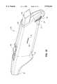
- FIGS. 1A, 1B and 1Care, respectively, perspective views of a presently preferred mechanical cardiac tissue removal device showing the atraumatic tissue contact portion and showing alternative single handed grasping positions which may be used to operate the device.
- FIG. 1Dis a rear side, perspective view of just the proximal portion of the handpiece of the device showing the depth control actuator and gauge.
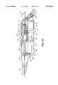
- FIGS. 2A and 2Bare, respectively, side views taken from generally rear and front perspectives with the side of the housing removed.
- FIGS. 2C and 2Dare, respectively, a side view of the components of the handpiece of the device, showing the spring component of the sequencing bar, and a cross sectional view taken along lines A--A of FIG. 2C.
- FIG. 2Eis a perspective view of the sequencing bar showing the gear rack and slot.
- FIG. 2Fis a cross sectional view of the depth control setting mechanism taken along lines E--E of FIG. 2C.
- FIG. 3is a mechanical schematic view of the major components and component relationships of the mechanical cardiac tissue removal device.
- FIGS. 4A-4Gare mechanical schematic views similar to FIG. 3 and illustrating changing component relationships during the various stages of formation of a myocardial revascularization pathway.
- FIG. 5is an enlarged view of the distal end of a referred cutting tip assembly showing the positions of the cooperating distal end of the stylet and the cutting edge of the hypotube at completion of a cutting operation.
- FIG. 6is a side sectional view of the torquable shaft portion of the mechanical cardiac tissue removal device.
- FIGS. 7A-7Fare sequential views of the cutting tip assembly entering and exiting tissue to create a pathway or take a tissue sample.
- FIGS. 8A-8Eare views of alternative housings for a mechanical cardiac tissue removal device.
- FIGS. 1A-1Done exemplary presently preferred embodiment of a mechanical cardiac tissue removal device suitable for biopsy and/or myocardial revascularization is illustrated generally as reference number 20 in FIGS. 1A-1D.
- the cardiac tissue removal device 20is particularly suitable for surgical or minimally invasive(MIS) myocardial revascularization and/or biopsy and may be held in the hand in several positions, as illustrated in FIGS. 1B and 1C, for single handed, left or right hand, operation to obtain biopsy samples or create myocardial revascularization pathways.
- MISminimally invasive
- a pathwaymeans a revascularization channel which extends into myocardium, may or may not communicate with the ventricle, and a stimulation zone or channel which results in revascularization but is not expected to remain completely patent for extended periods.
- the semi-automatic device 20perforates the epicardium of the heart, places the stylet within the myocardium, rotates and advances the hypotube around and over the stylet, and captures the excised tissue within the device for complete removal, as described in detail below.
- the preferred mechanical cardiac tissue removal device 20includes a hand piece 22 which is a housing molded or machined from a plastic material, and defining a contoured surface defining one or more finger grip indentations 24 which provide tactile feedback regarding the position of the hand on the device so the physician need not look away from the medical procedure.
- the contoured surface with indentations 24further assists the user to securely hold the hand piece without slippage in at least two, different positions during either left or right handed operation of the device 20.
- a tapered neck portion 26extends from the hand piece 22 and may be a unitary portion of the hand piece 22, or may be separately molded, as shown, and attached to the hand piece 22.
- a shaft 30extends outwardly from the neck portion 26.
- the shaft 30may be constructed of metal, plastic or composite materials and may be malleable to allow some ability to change the angle of orientation from axis "A". As shown, the torquable shaft 30 defines a generally J-shaped bend 32 and terminates in a protective tip 34. When the neck portion 26 is separately constructed, it may be made rotatable in which case the orientation of the bend 32 and the tip 34 may be altered. Suitable rotation mechanisms include conventional spring fingers, detentsi and ratchet assemblies, such as the ratchet mechanism 28 shown in FIG. 2A, allowing 360° rotation of the tapered nose 26. As an alternative to a curved shaft, the shaft 30 also may be straight if desired as shown in FIG. 8B. A conventional articulating joint 31 may also be included for changing the angle of orientation of the tip portion, particularly when inserting and using the device through a port in a minimally invasive procedure.
- the protective tip 34preferably is generally ball, cup or disc shaped and is designed to contact the heart and maintain contact of the device 20 on the heart during formation of a pathway and/or the taking of a biopsy sample.
- the protective tip 34may be constructed from generally yieldable materials such as silicone, soft elastic, rubber or foam and may also be metallic or plastic.
- the protective tip 34distributes contact forces on the heart, particularly during beating heart myocardial revascularization, and may be permanently attached to the shaft 30 or may be detachable with conventional snap-mount or screw mount mechanisms. Different detachable tips 34, such as suction and drug delivery tips, may be provided to accommodate size and access interests.
- the tissue contact surface of the protective tip 34may be textured to provide a gripping surface, and suction may be provided at the proximal end of the hand piece to extend through the shaft 30 to further secure the protective tip 34 to the heart.
- buttons or other conventional finger actuated mechanismsextend through the hand piece 22 to operate the cardiac tissue removal device 20.
- a push button 40extends out of the proximal end of the hand piece 22 to operate the device in a semi-automatic manner as described below.
- a second sliding button 42is operatively connected to the push button 40 thereby allowing operation of the device to be controlled from either of the hand positions shown in FIGS. 1B and 1C.
- a depth gauge 36preferably is provided on the side of the hand piece, and the selection of desired pathway or biopsy depth is controlled by thumb wheel 38 extending through handpiece slot 33. (FIG. 1D)
- the depth gauge 36is a sliding knob which protrudes through a slot 31 in the handpiece.
- Depth markingsare provided and may be matched with the position of the slidable knob. Selection of optimum depth for pathways depends upon a number of factors, including but not limited to the depth of the myocardium, the desired depth of the pathway, and whether the pathway is intended to communicate with the ventricle. Generally, the depth stop selector should allow selection of depths between about 0.5 mm to 3.5mm, and selection of a maximum depth of about 2.0 mm to 2.5 mm would avoid communication of a surgically created pathway with the ventricle of the heart. Determination of the depth of the heart wall may be done conventionally prior to performing the myocardial revascularization procedure, or the depth may be determined dynamically during the myocardial revascularization procedure using ultrasound as described in co-pending patent application Ser. No. 08/852,977, filed on May 6, 1997, entitled Ultrasound Device for Axial Ranging, incorporated by reference herein.
- a cutting tip assembly 50(FIG. 3) may be slidably extended through the shaft 30 and out of the protective tip 34 by pressing push button 40 or 42.
- the preferred components of the cutting tip assembly 50comprise a stylet 60 mounted within a hollow hypotube 70.
- the stylet 60 and the hypotube 70are preferably sequentially advanced into the heart tissue to create a pathway.
- the hollow hypotube 70may be a tapered tube as shown or a conventional biopsy needle, such as a soft tissue biopsy needle.
- the hypotube 70defines an interior wall 72 surrounding a lumen 74 and an exterior wall 76.
- the inner diameter of the lumenmay be approximately 0.5 to 2.5 mm depending upon the intended diameter of the pathway.
- the distal end of the hypotube 70defines an external beveled portion 77 which terminates to form a sharp cutting edge 78. Rotation of the hypotube 70, as described below, results in a sharp, clean cut by the beveled portion 77 and edge 78.
- the beveled portion 77 and the edge 78allow the rotating hypotube 70 to cut through tissue with minimal axial force.
- the stylet 60is mounted for translation within, and extension out of, the lumen 74 and comprises a rod 62 defining a distal plug 64.
- the styletpreferably is made of metal.
- the plug 64defines a generally central body 66 sized to closely fit within the lumen 74 while still allowing easy reciprocation within the lumen.
- the body 66further defines a proximal tapered portion 67 extending between the body and the rod 62.
- the tapered portion 67self aligns the stylet 60 within the lumen 74.
- a distal tapered portion 68extends from the distal end of the body 66 to form a piercer 69.
- the plugsubstantially closes off the lumen 74 thereby forming a tissue reservoir with support for the excised tissue within provided by the generally central rod 62.
- the plugserves several functions.
- the piercer 69pierces the heart wall to allow insertion of the hypotube, the rod 62 holds tissue stationary as the tissue collapses in around the rod during cutting, and the body 66, in conjunction with the hypotube 70, finishes off the cutting of a pathway and closes off the distal end of the lumen 74 to form a reservoir for cut tissue.
- the cutting tip assemblyis advanced through the shaped portion 32 of the shaft 30 using a torquable, bendable shaft insert 115.
- the torquable insert 115is a coiled wire spring 182, or wire mesh proximal tubing portion, attached located near the distal end of the cutting tip assembly to provide flexibility to allow the cutting tip assembly to follow the bend 32 in the shaft 30.
- the torquable shaft insert 115also may be constructed from a shape memory material such as nitinol.
- FIGS. 2A-2Eshow the major components for controlling the cutting tip assembly 50 of the cardiac tissue removal device 20, and FIG. 3 shows such components diagrammatically to illustrate the operating relationships between the components.
- the semi-automatic operation of the cardiac tissue removal devicesequentially activates the components to accomplish a pathway forming sequence.
- the shaft 41is a generally L shaped bar which is connected to the primary operating component of the device 20, a sequencing bar 96, by a gear mechanism 44 mounted on the shaft 41 as best shown in FIG. 2E.
- the gear mechanism 44engages the smaller one of a cluster gear 98 operatively attached to a gear rack of the sequencing bar 96 .
- the cluster gear mechanism 98allows a relatively short button stroke to produce a longer travel distance of the sequencing bar 96 which is attached to the larger gear of the cluster gear 98.
- the sequencing bar 96is best shown in FIG. 2E and is the primary movable component which sequentially controls movement and operation of other components, including the cutting tip assembly 50.
- the sequencing bar 96is a generally tubular structure defining flanges and slots designed to sequentially and separately control movement of the stylet 60 and the hypotube 70 relative to the sequencing bar 96 as the bar 96 is advanced.
- Axially extending flanges 95secure positional alignment of the sequencing bar to the housing 22 by being slidably engaged in housing slots 23, as best shown in FIG. 2D.
- FIG. 2Cshowing some of the interior components of the sequencing bar, a ferrule 94 within a pocket 103 is used to attach one end of a spring 101 to the sequencing bar 96.
- the opposite end of the spring 101is connected to a cap 61.
- the sequencing bar 96moves axially towards the distal tip of the device 20, the stylet 60 is pushed along with the bar by the spring 97, as best shown in FIG. 2C.
- a slot 93 in the sequencing bar 96is provided for travel of a stylet stop 63 associated with the ferrule 94, pocket 103 assembly.
- the stop 63prevents further advancement of the stylet 60 relative to the sequencing bar 96 when the stop 63 contacts a portion of the depth control mechanism as described below.
- axle 90is then pushed forward when sequencing bar 96 comes into contact with flange 92.
- Tab 63contacts flange 61 in slot 93 to stop movement of axle 90.
- the sequencing bar 96further defines an axle stop 100 which limits axial travel of an axle 90.
- a return spring 99also may be provided on the sequencing bar 96 and attached to the housing of the device, or to the button 40, to bias the sequencing bar 96 in its most proximal position when force is released from button 40 or 42.
- the position of the nut 104is adjusted relative to a stop axle mechanism 106.
- a spring detent 108Releasably connected to the stop axle mechanism is a spring detent 108 (FIG. 3).
- the depth adjustment assemblyaffects travel distance of both the stylet 60, as the stylet contacts nut 104, and ultimately the hypotube 70 attached thereto using one setting, depth setting mechanism 36, 38.
- the detent 108pulls the depth adjustment assembly along with the moving sequencing bar until contact occurs with a stationary rib on the housing 22.
- Alternative depth stop mechanismsmay be used, including but not limited to a ratchet or cammed mechanism, and discrete stops may be provided.
- the semi-automatic operationis provided by a small motor 80, for example a Micro-Mo 6 Volt DC motor, powered by a battery 82, such as a DuracellTM 2/3A Li/MnO2 battery, or may have an air, fluid, or other known actuation mechanism to cause rotation.
- Operation of the motor 80causes rotation of an armature shaft 84 which terminates in a drive gear mechanism having 1 or more gears such as spur gears 86, 88.
- Gear 88attaches, and is preferably keyed, to an axle 90. Rotation of the gears 86, 88 transmits torque and rotational movement in a clockwise or counterclockwise direction to the hollow axle 90 which defines a proximal flange 92 and houses the cutting tip assembly 50.
- Activation of the motor 80occurs only when electrical contact is made between the sequencing bar 96 and a contact plate of the motor 80 to complete a circuit between the motor 80 and batteries 82.
- a contact switch 91may be used and is tripped as shown in FIG. 3 when contacted by a sequencing bar 96.
- FIGS. 4A-4G and FIGS. 7A-7FOperation of the cardiac tissue removal device 20 to form a pathway and/or obtain a biopsy sample is best illustrated in FIGS. 4A-4G and FIGS. 7A-7F.
- the cutting tip assembly 50is shown positioned over a wall of the heart, in this case, the epicardium 12, prior to initiating pathway formation.
- the hypotubeis positioned over and around the plug 64.
- FIGS. 4B and 7Bshow initiation of pathway formation by pushing button 40 or 42 to insert the cutting tip assembly 50 through the epicardium 12 so that the piercer can spread the epicardium apart and allow entry of the distal end of the hypotube 70 through the epicardium with minimal trauma thereto.
- button 40, 42activates only the sequencing bar 96 to set into motion an entire sequence of events resulting in formation of a pathway.
- FIGS. 4C and 7Cshow advancement of the stylet 60 to its maximum depth by depressing push button 40.
- the sequencing bar 96advances in direction "F"
- the detent 108is pulled forward and disengages from the axle stop 106 and the stylet 60 is pushed in direction "F” by spring 101.
- the stylet 60advances and spreads the myocardium 10 until it reaches the preset distance, determined by the depth setting mechanism, and the stop 63 engages nut 104.
- the push button 40is fully actuated, the still advancing sequencing bar 96 makes electrical contact with the motor 80 to cause rotation of the axle 90 and hypotube 70 as the needle 70 begins to advance behind the stylet 60.
- the excised tissueis held stationary by the stylet 60 until the hypotube 70 reaches its maximum depth, as shown in FIGS. 4E and 7E, when the axle flange 92 contacts the stop mechanism.
- release of the push button 40causes the biasing return spring 99 to retract the sequencing bar 96 and, during the first half of the retraction cycle, maintains the relative positions of the stylet and hypotube thereby maintaining the integrity of the tissue reservoir.
- the motor 80shuts off when the sequencing bar 96 clears the micro switch 94 and the components return to the initial starting positions at the end of the retraction cycle.
- the cutting tip assembly 50may be retracted by reversing the direction of travel of the buttons 40, 42.
- the reservoir of the cardiac tissue removal deviceis suitable for storage of multiple tissue samples prior to cleaning, which is particularly suitable when the formed pathways do not communicate with the ventricle, or the tissue may be manually removed from the stylet between formation of pathways to reduce any risks of emboli when the formed pathways communicate with the ventricle.
- the stylet 60may be removed from the cardiac tissue removal device for cleaning, or the user may wipe the stylet rod to remove excised tissue.
- Suctionmay be applied if desired during pathway formation and drugs such as VEGF may be deposited in the pathways to stimulate angiogenesis.
- FIGS. 8A through 8ESeveral alternative hand piece designs for the cardiac tissue removal device are shown in FIGS. 8A through 8E, although other configurations may be used.
- the creation of viable pathways using the cutting tip assemblies, with or without the hand pieces discussed above,may by performed by first heating one or more of the cutting tip assembly to a temperature of at least 60 degrees Celsius. This provides thermal damage to the heart wall 10, in addition to the thermal damage created from frictional engagement of the cutting tip assembly. The use of heat simulates the thermal shock of the prior art laser methods.
- a separate heating element(not shown), such as a conventional thermal band(not shown)may be provided to ensure that each cutting tip assembly is heated.
- a plurality of detachable styletsmay be heated in an oven or heating block(not shown) and attached with a snap lock or quick disconnect mechanism to the hand piece.
- the torquable shaft portionmay be extended the length of the cutting tip assembly to create a flexible assembly for insertion through a catheter to form pathways from the inside of the left ventricle of the heart.
- a steerable or torquable catheteris inserted conventionally through the vasculature, perhaps through the femoral artery, into the ventricle using a conventional guidewire.
- the guidewireis removed and the torquable cutting tip assembly is introduced to the ventricle for creation of pathways.
- Control of the deviceis accomplished using an exterior handpiece having the components described herein, particularly the depth control mechanism to ensure the created pathways do not penetrate the epicardium.
- both the stylet and the hypotubemay rotate during at least part of a sequence and the sequencing bar may be altered to trigger rotation and advancement of the hypotube close behind the advancing stylet.
- Other configurations of the distal end of the stylet and the cutting edge of the hypotubemay be used to create cooperating geometries.
- the motormay be configured to require operator activation instead of being automatically tripped, and suction may be used for removal of excised tissue from the stylet.
- the housingmay be made of materials other than plastic and may be configured differently to provide alternative designs. The scope of the present invention is therefore limited only by the scope of the claims appended hereto.
Landscapes
- Health & Medical Sciences (AREA)
- Life Sciences & Earth Sciences (AREA)
- Surgery (AREA)
- Medical Informatics (AREA)
- Engineering & Computer Science (AREA)
- Biomedical Technology (AREA)
- Heart & Thoracic Surgery (AREA)
- Molecular Biology (AREA)
- Animal Behavior & Ethology (AREA)
- General Health & Medical Sciences (AREA)
- Public Health (AREA)
- Veterinary Medicine (AREA)
- Nuclear Medicine, Radiotherapy & Molecular Imaging (AREA)
- Orthopedic Medicine & Surgery (AREA)
- Pathology (AREA)
- Surgical Instruments (AREA)
Abstract
Description
Claims (32)
Priority Applications (4)
| Application Number | Priority Date | Filing Date | Title |
|---|---|---|---|
| US08/908,816US5976164A (en) | 1996-09-13 | 1997-08-08 | Method and apparatus for myocardial revascularization and/or biopsy of the heart |
| CA002244596ACA2244596A1 (en) | 1997-08-08 | 1998-07-31 | Method and apparatus for myocardial revascularization and/or biopsy of the heart |
| EP98306298AEP0895752A1 (en) | 1997-08-08 | 1998-08-06 | Apparatus for sampling heart tissue and/or myocardial revascularization by mechanical cutting |
| AU78860/98AAU7886098A (en) | 1997-08-08 | 1998-08-07 | Method and apparatus for myocardial revascularization and/or biopsy of the heart |
Applications Claiming Priority (2)
| Application Number | Priority Date | Filing Date | Title |
|---|---|---|---|
| US08/713,531US5871495A (en) | 1996-09-13 | 1996-09-13 | Method and apparatus for mechanical transmyocardial revascularization of the heart |
| US08/908,816US5976164A (en) | 1996-09-13 | 1997-08-08 | Method and apparatus for myocardial revascularization and/or biopsy of the heart |
Related Parent Applications (1)
| Application Number | Title | Priority Date | Filing Date |
|---|---|---|---|
| US08/713,531Continuation-In-PartUS5871495A (en) | 1996-09-13 | 1996-09-13 | Method and apparatus for mechanical transmyocardial revascularization of the heart |
Publications (1)
| Publication Number | Publication Date |
|---|---|
| US5976164Atrue US5976164A (en) | 1999-11-02 |
Family
ID=25426274
Family Applications (1)
| Application Number | Title | Priority Date | Filing Date |
|---|---|---|---|
| US08/908,816Expired - LifetimeUS5976164A (en) | 1996-09-13 | 1997-08-08 | Method and apparatus for myocardial revascularization and/or biopsy of the heart |
Country Status (4)
| Country | Link |
|---|---|
| US (1) | US5976164A (en) |
| EP (1) | EP0895752A1 (en) |
| AU (1) | AU7886098A (en) |
| CA (1) | CA2244596A1 (en) |
Cited By (111)
| Publication number | Priority date | Publication date | Assignee | Title |
|---|---|---|---|---|
| US6139541A (en)* | 1998-09-02 | 2000-10-31 | Heartstent Corporation | Guide for transmyocardial implant |
| US6162214A (en)* | 1997-10-30 | 2000-12-19 | Eclipse Surgical Technologies, Inc. | Corning device for myocardial revascularization |
| US6171251B1 (en) | 1998-07-14 | 2001-01-09 | Eclipse Surgical Technologies, Inc. | Method and apparatus for optimizing direct vessel implants for myocardial revascularization |
| US6200311B1 (en) | 1998-01-20 | 2001-03-13 | Eclipse Surgical Technologies, Inc. | Minimally invasive TMR device |
| US6273862B1 (en)* | 1998-10-23 | 2001-08-14 | Ethicon Endo-Surgery, Inc | Surgical device for the collection of soft tissue |
| WO2001058361A1 (en)* | 2000-02-11 | 2001-08-16 | Iotek, Inc. | Organ tissue manipulator |
| US20010047183A1 (en)* | 2000-04-05 | 2001-11-29 | Salvatore Privitera | Surgical device for the collection of soft tissue |
| US6361504B1 (en)* | 1997-03-31 | 2002-03-26 | Myoung Chul Shin | Biopsy needle, method for fabricating, and apparatus for operating the same |
| WO2003077767A1 (en)* | 2002-03-19 | 2003-09-25 | Bard Dublin Itc Limited | Vacuum biopsy device |
| US6641604B1 (en) | 2000-02-11 | 2003-11-04 | Iotek, Inc. | Devices and method for manipulation of organ tissue |
| US6663622B1 (en) | 2000-02-11 | 2003-12-16 | Iotek, Inc. | Surgical devices and methods for use in tissue ablation procedures |
| US6669691B1 (en) | 2000-07-18 | 2003-12-30 | Scimed Life Systems, Inc. | Epicardial myocardial revascularization and denervation methods and apparatus |
| US6689072B2 (en)* | 1999-03-23 | 2004-02-10 | Leopold S. Kaplan | Biopsy needle instrument |
| US6695866B1 (en) | 1998-07-15 | 2004-02-24 | St. Jude Medical, Inc. | Mitral and tricuspid valve repair |
| US6695859B1 (en) | 1999-04-05 | 2004-02-24 | Coalescent Surgical, Inc. | Apparatus and methods for anastomosis |
| US20040092998A1 (en)* | 2001-10-18 | 2004-05-13 | Kevin Sniffin | Anastomosis instrument and method for performing same |
| US20040210161A1 (en)* | 1999-12-17 | 2004-10-21 | Burdorff Mark A. | Surgical biopsy system with remote control for selecting an operational mode |
| US20050101879A1 (en)* | 2003-11-06 | 2005-05-12 | Shidham Vinod B. | Needle aspiration biopsy device and method |
| US20050165328A1 (en)* | 2002-03-19 | 2005-07-28 | Norbert Heske | Biopsy device and biopsy needle module that can be inserted into the biopsy device |
| US20050222568A1 (en)* | 2004-03-31 | 2005-10-06 | Wilson-Cook Medical Inc. | Adjustable handle for a medical device |
| WO2005110254A1 (en)* | 2004-05-13 | 2005-11-24 | Umc Utrecht Holding B.V. | Device for making a cut in a tissue |
| US20050267061A1 (en)* | 2004-04-08 | 2005-12-01 | Sangamo Biosciences, Inc. | Methods and compositions for treating neuropathic and neurodegenerative conditions |
| US20060079475A1 (en)* | 2004-04-08 | 2006-04-13 | Sangamo Biosciences, Inc. | Methods and compositions for modulating cardiac contractility |
| US20060173377A1 (en)* | 2005-01-31 | 2006-08-03 | Mccullough Adam B | Quick cycle biopsy system |
| US20060229528A1 (en)* | 2003-03-29 | 2006-10-12 | C. R. Brad, Inc. | Coaxial cannula provided with a sealing element |
| US7195142B2 (en) | 2003-05-30 | 2007-03-27 | Tyco Healthcare Group Lp | End-to-end anastomosis instrument and method for performing same |
| US20070238177A1 (en)* | 2006-01-25 | 2007-10-11 | Laham Roger J | Devices and methods for tissue transplant and regeneration |
| US20080140104A1 (en)* | 2002-01-22 | 2008-06-12 | Cardica, Inc. | Surgical Tool for Creating an Opening in Tissue |
| US7547313B2 (en) | 1998-06-03 | 2009-06-16 | Medtronic, Inc. | Tissue connector apparatus and methods |
| US7569062B1 (en)* | 1998-07-15 | 2009-08-04 | St. Jude Medical, Inc. | Mitral and tricuspid valve repair |
| US7591790B2 (en) | 2001-03-23 | 2009-09-22 | Stryker Puerto Rico Limited | Micro-invasive device |
| US20090270889A1 (en)* | 2006-09-13 | 2009-10-29 | Vascular Treatment Device | Vascular Treatment Device |
| US7635385B2 (en) | 1996-07-23 | 2009-12-22 | Keith Milliman | Anastomosis instrument and method for performing same |
| US7722643B2 (en) | 1999-03-01 | 2010-05-25 | Medtronic, Inc. | Tissue connector apparatus and methods |
| US7744611B2 (en) | 2000-10-10 | 2010-06-29 | Medtronic, Inc. | Minimally invasive valve repair procedure and apparatus |
| US7743958B2 (en) | 2002-05-31 | 2010-06-29 | Tyco Healthcare Group Lp | End-to-end anastomosis instrument and method for performing same |
| US7763040B2 (en) | 1998-06-03 | 2010-07-27 | Medtronic, Inc. | Tissue connector apparatus and methods |
| US7762961B2 (en) | 2003-03-29 | 2010-07-27 | C. R. Bard, Inc. | Pressure generating unit |
| US7806835B2 (en) | 2007-11-20 | 2010-10-05 | Devicor Medical Products, Inc. | Biopsy device with sharps reduction feature |
| US7858038B2 (en) | 2007-11-20 | 2010-12-28 | Devicor Medical Products, Inc. | Biopsy device with illuminated tissue holder |
| US7879047B2 (en) | 2003-12-10 | 2011-02-01 | Medtronic, Inc. | Surgical connection apparatus and methods |
| WO2011019343A1 (en)* | 2009-08-12 | 2011-02-17 | C.R. Bard, Inc. | Biopsy appaparatus having integrated thumbwheel mechanism for manual rotation of biopsy cannula |
| US7896892B2 (en) | 2000-03-31 | 2011-03-01 | Medtronic, Inc. | Multiple bias surgical fastener |
| US20110077551A1 (en)* | 2009-09-25 | 2011-03-31 | Videbaek Karsten | Charging station for battery powered biopsy apparatus |
| US7938786B2 (en) | 2006-12-13 | 2011-05-10 | Devicor Medical Products, Inc. | Vacuum timing algorithm for biopsy device |
| US7963947B2 (en) | 2008-01-16 | 2011-06-21 | Pressure Products Medical Supplies, Inc. | Apparatus, system, and method of shielding the sharp tip of a transseptal guidewire |
| US7963973B2 (en) | 1998-06-03 | 2011-06-21 | Medtronic, Inc. | Multiple loop tissue connector apparatus and methods |
| US7976556B2 (en) | 2002-09-12 | 2011-07-12 | Medtronic, Inc. | Anastomosis apparatus and methods |
| US7981049B2 (en) | 2006-12-13 | 2011-07-19 | Devicor Medical Products, Inc. | Engagement interface for biopsy system vacuum module |
| US8029519B2 (en) | 2003-08-22 | 2011-10-04 | Medtronic, Inc. | Eversion apparatus and methods |
| US8052616B2 (en) | 2007-11-20 | 2011-11-08 | Devicor Medical Products, Inc. | Biopsy device with fine pitch drive train |
| US8052615B2 (en) | 2004-07-09 | 2011-11-08 | Bard Peripheral Vascular, Inc. | Length detection system for biopsy device |
| US8105345B2 (en) | 2002-10-04 | 2012-01-31 | Medtronic, Inc. | Anastomosis apparatus and methods |
| US8118822B2 (en) | 1999-03-01 | 2012-02-21 | Medtronic, Inc. | Bridge clip tissue connector apparatus and methods |
| US8177836B2 (en) | 2008-03-10 | 2012-05-15 | Medtronic, Inc. | Apparatus and methods for minimally invasive valve repair |
| US8187204B2 (en) | 2007-10-01 | 2012-05-29 | Suros Surgical Systems, Inc. | Surgical device and method for using same |
| US8211124B2 (en) | 2003-07-25 | 2012-07-03 | Medtronic, Inc. | Sealing clip, delivery systems, and methods |
| US8251916B2 (en) | 2006-12-13 | 2012-08-28 | Devicor Medical Products, Inc. | Revolving tissue sample holder for biopsy device |
| US8251917B2 (en) | 2006-08-21 | 2012-08-28 | C. R. Bard, Inc. | Self-contained handheld biopsy needle |
| US8262586B2 (en) | 2006-10-24 | 2012-09-11 | C. R. Bard, Inc. | Large sample low aspect ratio biopsy needle |
| US8262585B2 (en) | 2005-08-10 | 2012-09-11 | C. R. Bard, Inc. | Single-insertion, multiple sampling biopsy device with linear drive |
| US8267868B2 (en) | 2005-08-10 | 2012-09-18 | C. R. Bard, Inc. | Single-insertion, multiple sample biopsy device with integrated markers |
| US8282574B2 (en) | 2005-08-10 | 2012-10-09 | C. R. Bard, Inc. | Single-insertion, multiple sampling biopsy device usable with various transport systems and integrated markers |
| US20120330339A1 (en)* | 2011-06-22 | 2012-12-27 | Depuy Mitek, Inc. | Tissue cutting device, assembly and method |
| US20130023790A1 (en)* | 2011-07-19 | 2013-01-24 | Schaeffer Jeremy R | Biopsy device |
| US8394114B2 (en) | 2003-09-26 | 2013-03-12 | Medtronic, Inc. | Surgical connection apparatus and methods |
| US8430824B2 (en) | 2009-10-29 | 2013-04-30 | Bard Peripheral Vascular, Inc. | Biopsy driver assembly having a control circuit for conserving battery power |
| US8454532B2 (en) | 2007-12-27 | 2013-06-04 | Devicor Medical Products, Inc. | Clutch and valving system for tetherless biopsy device |
| US8454531B2 (en) | 2007-11-20 | 2013-06-04 | Devicor Medical Products, Inc. | Icon-based user interface on biopsy system control module |
| US8480595B2 (en) | 2006-12-13 | 2013-07-09 | Devicor Medical Products, Inc. | Biopsy device with motorized needle cocking |
| US8485987B2 (en) | 2006-10-06 | 2013-07-16 | Bard Peripheral Vascular, Inc. | Tissue handling system with reduced operator exposure |
| US8485989B2 (en) | 2009-09-01 | 2013-07-16 | Bard Peripheral Vascular, Inc. | Biopsy apparatus having a tissue sample retrieval mechanism |
| US8500697B2 (en) | 2007-10-19 | 2013-08-06 | Pressure Products Medical Supplies, Inc. | Transseptal guidewire |
| US8518060B2 (en) | 2009-04-09 | 2013-08-27 | Medtronic, Inc. | Medical clip with radial tines, system and method of using same |
| US8529583B1 (en) | 1999-09-03 | 2013-09-10 | Medtronic, Inc. | Surgical clip removal apparatus |
| US8597206B2 (en) | 2009-10-12 | 2013-12-03 | Bard Peripheral Vascular, Inc. | Biopsy probe assembly having a mechanism to prevent misalignment of components prior to installation |
| US8597205B2 (en) | 2007-12-20 | 2013-12-03 | C. R. Bard, Inc. | Biopsy device |
| US8668704B2 (en) | 2009-04-24 | 2014-03-11 | Medtronic, Inc. | Medical clip with tines, system and method of using same |
| US8690793B2 (en) | 2009-03-16 | 2014-04-08 | C. R. Bard, Inc. | Biopsy device having rotational cutting |
| US8696645B2 (en) | 2010-11-15 | 2014-04-15 | Vascular Insights Llc | Vascular treatment devices and methods |
| US8702623B2 (en) | 2008-12-18 | 2014-04-22 | Devicor Medical Products, Inc. | Biopsy device with discrete tissue chambers |
| US8708929B2 (en) | 2009-04-15 | 2014-04-29 | Bard Peripheral Vascular, Inc. | Biopsy apparatus having integrated fluid management |
| US8808200B2 (en) | 2007-10-01 | 2014-08-19 | Suros Surgical Systems, Inc. | Surgical device and method of using same |
| US8845548B2 (en) | 2009-06-12 | 2014-09-30 | Devicor Medical Products, Inc. | Cutter drive assembly for biopsy device |
| US8932233B2 (en) | 2004-05-21 | 2015-01-13 | Devicor Medical Products, Inc. | MRI biopsy device |
| US8979768B2 (en) | 1998-10-23 | 2015-03-17 | Devicor Medical Products, Inc. | Surgical device for the collection of soft tissue |
| US9039634B2 (en) | 2007-11-20 | 2015-05-26 | Devicor Medical Products, Inc. | Biopsy device tissue sample holder rotation control |
| WO2015026979A3 (en)* | 2013-08-22 | 2015-06-11 | Transmed7, Llc | Soft tissue coring biopsy devices and methods |
| US20150335379A1 (en)* | 2012-11-30 | 2015-11-26 | GYRUS ACMI, INC., d/b/a Olympus Surgical Technologies America | Integrated blade assembly and identification circuit |
| US9345457B2 (en) | 2006-12-13 | 2016-05-24 | Devicor Medical Products, Inc. | Presentation of biopsy sample by biopsy device |
| US9463001B2 (en) | 2013-05-28 | 2016-10-11 | Transmed7, Llc | Soft tissue coring biopsy devices and methods |
| US9638770B2 (en) | 2004-05-21 | 2017-05-02 | Devicor Medical Products, Inc. | MRI biopsy apparatus incorporating an imageable penetrating portion |
| US9795365B2 (en) | 2004-05-21 | 2017-10-24 | Devicor Medical Products, Inc. | MRI biopsy apparatus incorporating a sleeve and multi-function obturator |
| US9808226B2 (en) | 2011-10-15 | 2017-11-07 | Transmed7, Llc | Soft tissue coring biopsy devices and methods |
| EP3338646A1 (en)* | 2016-12-21 | 2018-06-27 | National University of Ireland Galway | A biopsy device |
| US10070884B2 (en) | 2013-09-12 | 2018-09-11 | Transmed7, Llc | Soft tissue coring biopsy devices and methods |
| WO2018203675A1 (en)* | 2017-05-04 | 2018-11-08 | 아주대학교산학협력단 | Microsurgical instrument capable of joint motion and rotational motion |
| US10231750B2 (en) | 2014-09-29 | 2019-03-19 | Transmed7, Llc | Excisional device distal working end actuation mechanism and method |
| US10285673B2 (en) | 2013-03-20 | 2019-05-14 | Bard Peripheral Vascular, Inc. | Biopsy device |
| US10456120B2 (en) | 2013-11-05 | 2019-10-29 | C. R. Bard, Inc. | Biopsy device having integrated vacuum |
| US10463350B2 (en) | 2015-05-01 | 2019-11-05 | C. R. Bard, Inc. | Biopsy device |
| US10595831B2 (en) | 2012-05-30 | 2020-03-24 | Devicor Medical Products, Inc. | Control for biopsy device |
| US20200163664A1 (en)* | 2013-08-30 | 2020-05-28 | Bioventrix, Inc. | Cardiac tissue anchoring devices, methods, and systems for treatment of congestive heart failure and other conditions |
| US10709429B2 (en) | 2016-12-05 | 2020-07-14 | Argon Medical Devices Inc. | Biopsy device handle |
| US11116483B2 (en) | 2017-05-19 | 2021-09-14 | Merit Medical Systems, Inc. | Rotating biopsy needle |
| US11179141B2 (en) | 2006-12-13 | 2021-11-23 | Devicor Medical Products, Inc. | Biopsy system |
| US11793498B2 (en) | 2017-05-19 | 2023-10-24 | Merit Medical Systems, Inc. | Biopsy needle devices and methods of use |
| US11844500B2 (en) | 2017-05-19 | 2023-12-19 | Merit Medical Systems, Inc. | Semi-automatic biopsy needle device and methods of use |
| US12150627B2 (en) | 2019-12-11 | 2024-11-26 | Merit Medical Systems, Inc. | Bone biopsy device and related methods |
| US12295556B2 (en) | 2019-09-27 | 2025-05-13 | Merit Medical Systems, Inc. | Rotation biopsy system and handle |
| US12419620B2 (en) | 2019-08-22 | 2025-09-23 | Argon Medical Devices, Inc. | Core-severing cannula for biopsy devices |
Families Citing this family (30)
| Publication number | Priority date | Publication date | Assignee | Title |
|---|---|---|---|---|
| US6165188A (en)* | 1996-12-02 | 2000-12-26 | Angiotrax, Inc. | Apparatus for percutaneously performing myocardial revascularization having controlled cutting depth and methods of use |
| US6051008A (en)* | 1996-12-02 | 2000-04-18 | Angiotrax, Inc. | Apparatus having stabilization members for percutaneously performing surgery and methods of use |
| US6102926A (en) | 1996-12-02 | 2000-08-15 | Angiotrax, Inc. | Apparatus for percutaneously performing myocardial revascularization having means for sensing tissue parameters and methods of use |
| US6641610B2 (en) | 1998-09-10 | 2003-11-04 | Percardia, Inc. | Valve designs for left ventricular conduits |
| US6254564B1 (en) | 1998-09-10 | 2001-07-03 | Percardia, Inc. | Left ventricular conduit with blood vessel graft |
| AU6384699A (en) | 1998-09-10 | 2000-04-03 | Percardia, Inc. | Tmr shunt |
| US6290728B1 (en) | 1998-09-10 | 2001-09-18 | Percardia, Inc. | Designs for left ventricular conduit |
| JP2002524196A (en) | 1998-09-10 | 2002-08-06 | パーカーディア,インコーポレイティド | Transmyocardial shunt for left ventricular revascularization and its mounting mechanism |
| US6409697B2 (en) | 1999-05-04 | 2002-06-25 | Heartstent Corporation | Transmyocardial implant with forward flow bias |
| US7033372B1 (en) | 1999-08-04 | 2006-04-25 | Percardia, Inc. | Corkscrew reinforced left ventricle to coronary artery channel |
| US6638237B1 (en) | 1999-08-04 | 2003-10-28 | Percardia, Inc. | Left ventricular conduits and methods for delivery |
| US6854467B2 (en) | 2000-05-04 | 2005-02-15 | Percardia, Inc. | Methods and devices for delivering a ventricular stent |
| EP1301228B1 (en) | 2000-07-13 | 2008-07-23 | Abbott Cardiovascular Systems Inc. | Deployment system for myocardial cellular material |
| US6976990B2 (en) | 2001-01-25 | 2005-12-20 | Percardia, Inc. | Intravascular ventriculocoronary bypass via a septal passageway |
| US7008397B2 (en) | 2002-02-13 | 2006-03-07 | Percardia, Inc. | Cardiac implant and methods |
| US7326219B2 (en) | 2002-09-09 | 2008-02-05 | Wilk Patent Development | Device for placing transmyocardial implant |
| US8308708B2 (en) | 2003-07-15 | 2012-11-13 | Abbott Cardiovascular Systems Inc. | Deployment system for myocardial cellular material |
| DE102005003632A1 (en) | 2005-01-20 | 2006-08-17 | Fraunhofer-Gesellschaft zur Förderung der angewandten Forschung e.V. | Catheter for the transvascular implantation of heart valve prostheses |
| US7896915B2 (en) | 2007-04-13 | 2011-03-01 | Jenavalve Technology, Inc. | Medical device for treating a heart valve insufficiency |
| US9044318B2 (en) | 2008-02-26 | 2015-06-02 | Jenavalve Technology Gmbh | Stent for the positioning and anchoring of a valvular prosthesis |
| BR112012021347A2 (en) | 2008-02-26 | 2019-09-24 | Jenavalve Tecnology Inc | stent for positioning and anchoring a valve prosthesis at an implantation site in a patient's heart |
| US10856978B2 (en) | 2010-05-20 | 2020-12-08 | Jenavalve Technology, Inc. | Catheter system |
| WO2011147849A1 (en) | 2010-05-25 | 2011-12-01 | Jenavalve Technology Inc. | Prosthetic heart valve and transcatheter delivered endoprosthesis comprising a prosthetic heart valve and a stent |
| CN105491978A (en) | 2013-08-30 | 2016-04-13 | 耶拿阀门科技股份有限公司 | Radially collapsible frame for a prosthetic valve and method for manufacturing such a frame |
| EP3270825B1 (en) | 2015-03-20 | 2020-04-22 | JenaValve Technology, Inc. | Heart valve prosthesis delivery system |
| US10709555B2 (en) | 2015-05-01 | 2020-07-14 | Jenavalve Technology, Inc. | Device and method with reduced pacemaker rate in heart valve replacement |
| WO2017195125A1 (en) | 2016-05-13 | 2017-11-16 | Jenavalve Technology, Inc. | Heart valve prosthesis delivery system and method for delivery of heart valve prosthesis with introducer sheath and loading system |
| WO2018138658A1 (en) | 2017-01-27 | 2018-08-02 | Jenavalve Technology, Inc. | Heart valve mimicry |
| CN115363701A (en)* | 2022-09-28 | 2022-11-22 | 深圳臣诺医疗器械有限公司 | Ultrasonic scalpel and surgical instrument |
| WO2024102411A1 (en) | 2022-11-09 | 2024-05-16 | Jenavalve Technology, Inc. | Catheter system for sequential deployment of an expandable implant |
Citations (20)
| Publication number | Priority date | Publication date | Assignee | Title |
|---|---|---|---|---|
| US4461305A (en)* | 1981-09-04 | 1984-07-24 | Cibley Leonard J | Automated biopsy device |
| US4576162A (en)* | 1983-03-30 | 1986-03-18 | Mccorkle Charles E | Apparatus and method for separation of scar tissue in venous pathway |
| US4658817A (en)* | 1985-04-01 | 1987-04-21 | Children's Hospital Medical Center | Method and apparatus for transmyocardial revascularization using a laser |
| US4850354A (en)* | 1987-08-13 | 1989-07-25 | Baxter Travenol Laboratories, Inc. | Surgical cutting instrument |
| US5263959A (en)* | 1991-10-21 | 1993-11-23 | Cathco, Inc. | Dottering auger catheter system and method |
| US5358472A (en)* | 1992-01-13 | 1994-10-25 | Schneider (Usa) Inc. | Guidewire atherectomy catheter and method of using the same |
| US5366468A (en)* | 1993-11-09 | 1994-11-22 | Linvatec Corporation | Double bladed surgical router having aspiration ports within flutes |
| US5380316A (en)* | 1990-12-18 | 1995-01-10 | Advanced Cardiovascular Systems, Inc. | Method for intra-operative myocardial device revascularization |
| US5403311A (en)* | 1993-03-29 | 1995-04-04 | Boston Scientific Corporation | Electro-coagulation and ablation and other electrotherapeutic treatments of body tissue |
| US5477862A (en)* | 1994-03-14 | 1995-12-26 | Haaga; John R. | Cutting tip for biopsy needle |
| WO1996035469A1 (en)* | 1995-05-10 | 1996-11-14 | Cardiogenesis Corporation | System for treating or diagnosing heart tissue |
| US5591159A (en)* | 1994-11-09 | 1997-01-07 | Taheri; Syde A. | Transcavitary myocardial perfusion apparatus |
| US5632755A (en)* | 1992-11-09 | 1997-05-27 | Endo Vascular Intruments, Inc. | Intra-artery obstruction clearing apparatus and methods |
| US5658272A (en)* | 1992-09-15 | 1997-08-19 | Hasson; Harrith M. | Surgical instrument support and method of using the same |
| EP0807412A1 (en)* | 1996-05-13 | 1997-11-19 | United States Surgical Corporation | Coring device and method |
| US5702412A (en)* | 1995-10-03 | 1997-12-30 | Cedars-Sinai Medical Center | Method and devices for performing vascular anastomosis |
| US5741287A (en)* | 1996-11-01 | 1998-04-21 | Femrx, Inc. | Surgical tubular cutter having a tapering cutting chamber |
| WO1998019614A1 (en)* | 1996-11-08 | 1998-05-14 | Fogarty Thomas J | Transvascular tmr device and method |
| US5794626A (en)* | 1994-08-18 | 1998-08-18 | Kieturakis; Maciej J. | Excisional stereotactic apparatus |
| US5807277A (en)* | 1995-12-15 | 1998-09-15 | Swaim; William R. | Biopsy hand tool for capturing tissue sample |
Family Cites Families (2)
| Publication number | Priority date | Publication date | Assignee | Title |
|---|---|---|---|---|
| DK145593A (en)* | 1993-12-23 | 1995-06-24 | Joergen A Rygaard | Surgical double instrument for performing connection mlm. arteries (end-to-side anastomosis) |
| US5715832A (en)* | 1995-02-28 | 1998-02-10 | Boston Scientific Corporation | Deflectable biopsy catheter |
- 1997
- 1997-08-08USUS08/908,816patent/US5976164A/ennot_activeExpired - Lifetime
- 1998
- 1998-07-31CACA002244596Apatent/CA2244596A1/ennot_activeAbandoned
- 1998-08-06EPEP98306298Apatent/EP0895752A1/ennot_activeWithdrawn
- 1998-08-07AUAU78860/98Apatent/AU7886098A/ennot_activeAbandoned
Patent Citations (20)
| Publication number | Priority date | Publication date | Assignee | Title |
|---|---|---|---|---|
| US4461305A (en)* | 1981-09-04 | 1984-07-24 | Cibley Leonard J | Automated biopsy device |
| US4576162A (en)* | 1983-03-30 | 1986-03-18 | Mccorkle Charles E | Apparatus and method for separation of scar tissue in venous pathway |
| US4658817A (en)* | 1985-04-01 | 1987-04-21 | Children's Hospital Medical Center | Method and apparatus for transmyocardial revascularization using a laser |
| US4850354A (en)* | 1987-08-13 | 1989-07-25 | Baxter Travenol Laboratories, Inc. | Surgical cutting instrument |
| US5380316A (en)* | 1990-12-18 | 1995-01-10 | Advanced Cardiovascular Systems, Inc. | Method for intra-operative myocardial device revascularization |
| US5263959A (en)* | 1991-10-21 | 1993-11-23 | Cathco, Inc. | Dottering auger catheter system and method |
| US5358472A (en)* | 1992-01-13 | 1994-10-25 | Schneider (Usa) Inc. | Guidewire atherectomy catheter and method of using the same |
| US5658272A (en)* | 1992-09-15 | 1997-08-19 | Hasson; Harrith M. | Surgical instrument support and method of using the same |
| US5632755A (en)* | 1992-11-09 | 1997-05-27 | Endo Vascular Intruments, Inc. | Intra-artery obstruction clearing apparatus and methods |
| US5403311A (en)* | 1993-03-29 | 1995-04-04 | Boston Scientific Corporation | Electro-coagulation and ablation and other electrotherapeutic treatments of body tissue |
| US5366468A (en)* | 1993-11-09 | 1994-11-22 | Linvatec Corporation | Double bladed surgical router having aspiration ports within flutes |
| US5477862A (en)* | 1994-03-14 | 1995-12-26 | Haaga; John R. | Cutting tip for biopsy needle |
| US5794626A (en)* | 1994-08-18 | 1998-08-18 | Kieturakis; Maciej J. | Excisional stereotactic apparatus |
| US5591159A (en)* | 1994-11-09 | 1997-01-07 | Taheri; Syde A. | Transcavitary myocardial perfusion apparatus |
| WO1996035469A1 (en)* | 1995-05-10 | 1996-11-14 | Cardiogenesis Corporation | System for treating or diagnosing heart tissue |
| US5702412A (en)* | 1995-10-03 | 1997-12-30 | Cedars-Sinai Medical Center | Method and devices for performing vascular anastomosis |
| US5807277A (en)* | 1995-12-15 | 1998-09-15 | Swaim; William R. | Biopsy hand tool for capturing tissue sample |
| EP0807412A1 (en)* | 1996-05-13 | 1997-11-19 | United States Surgical Corporation | Coring device and method |
| US5741287A (en)* | 1996-11-01 | 1998-04-21 | Femrx, Inc. | Surgical tubular cutter having a tapering cutting chamber |
| WO1998019614A1 (en)* | 1996-11-08 | 1998-05-14 | Fogarty Thomas J | Transvascular tmr device and method |
Cited By (242)
| Publication number | Priority date | Publication date | Assignee | Title |
|---|---|---|---|---|
| US7635385B2 (en) | 1996-07-23 | 2009-12-22 | Keith Milliman | Anastomosis instrument and method for performing same |
| US6361504B1 (en)* | 1997-03-31 | 2002-03-26 | Myoung Chul Shin | Biopsy needle, method for fabricating, and apparatus for operating the same |
| US6162214A (en)* | 1997-10-30 | 2000-12-19 | Eclipse Surgical Technologies, Inc. | Corning device for myocardial revascularization |
| US6200311B1 (en) | 1998-01-20 | 2001-03-13 | Eclipse Surgical Technologies, Inc. | Minimally invasive TMR device |
| US7547313B2 (en) | 1998-06-03 | 2009-06-16 | Medtronic, Inc. | Tissue connector apparatus and methods |
| US7763040B2 (en) | 1998-06-03 | 2010-07-27 | Medtronic, Inc. | Tissue connector apparatus and methods |
| US7963973B2 (en) | 1998-06-03 | 2011-06-21 | Medtronic, Inc. | Multiple loop tissue connector apparatus and methods |
| US6171251B1 (en) | 1998-07-14 | 2001-01-09 | Eclipse Surgical Technologies, Inc. | Method and apparatus for optimizing direct vessel implants for myocardial revascularization |
| US6695866B1 (en) | 1998-07-15 | 2004-02-24 | St. Jude Medical, Inc. | Mitral and tricuspid valve repair |
| US7569062B1 (en)* | 1998-07-15 | 2009-08-04 | St. Jude Medical, Inc. | Mitral and tricuspid valve repair |
| US20040167539A1 (en)* | 1998-07-15 | 2004-08-26 | St. Jude Medical, Inc. | Mitral and tricuspid valve repair |
| US6139541A (en)* | 1998-09-02 | 2000-10-31 | Heartstent Corporation | Guide for transmyocardial implant |
| US10166010B2 (en) | 1998-10-23 | 2019-01-01 | Devicor Medical Products, Inc. | Surgical device for the collection of soft tissue |
| US6273862B1 (en)* | 1998-10-23 | 2001-08-14 | Ethicon Endo-Surgery, Inc | Surgical device for the collection of soft tissue |
| US8206409B2 (en) | 1998-10-23 | 2012-06-26 | Devicor Medical Products, Inc. | Surgical device for the collection of soft tissue |
| US9433402B2 (en) | 1998-10-23 | 2016-09-06 | Devicor Medical Products, Inc. | Surgical device for the collection of soft tissue |
| US8016844B2 (en) | 1998-10-23 | 2011-09-13 | Devicor Medical Products, Inc. | Surgical device for the collection of soft tissue |
| US8979768B2 (en) | 1998-10-23 | 2015-03-17 | Devicor Medical Products, Inc. | Surgical device for the collection of soft tissue |
| US8118822B2 (en) | 1999-03-01 | 2012-02-21 | Medtronic, Inc. | Bridge clip tissue connector apparatus and methods |
| US7722643B2 (en) | 1999-03-01 | 2010-05-25 | Medtronic, Inc. | Tissue connector apparatus and methods |
| US8353921B2 (en) | 1999-03-01 | 2013-01-15 | Medtronic, Inc | Tissue connector apparatus and methods |
| US7892255B2 (en) | 1999-03-01 | 2011-02-22 | Medtronic, Inc. | Tissue connector apparatus and methods |
| US6689072B2 (en)* | 1999-03-23 | 2004-02-10 | Leopold S. Kaplan | Biopsy needle instrument |
| US7938840B2 (en) | 1999-04-05 | 2011-05-10 | Medtronic, Inc. | Apparatus and methods for anastomosis |
| US6695859B1 (en) | 1999-04-05 | 2004-02-24 | Coalescent Surgical, Inc. | Apparatus and methods for anastomosis |
| US8211131B2 (en) | 1999-04-05 | 2012-07-03 | Medtronic, Inc. | Apparatus and methods for anastomosis |
| US8529583B1 (en) | 1999-09-03 | 2013-09-10 | Medtronic, Inc. | Surgical clip removal apparatus |
| US7914464B2 (en) | 1999-12-17 | 2011-03-29 | Devicor Medical Products, Inc. | Surgical biopsy system with control unit for selecting an operational mode |
| US8460207B2 (en) | 1999-12-17 | 2013-06-11 | Devicor Medical Products, Inc. | Surgical biopsy system with remote control for selecting an operational mode |
| US20110160610A1 (en)* | 1999-12-17 | 2011-06-30 | Devicor Medical Products, Inc. | Surgical biopsy system with remote control for selecting an operational mode |
| US9039635B2 (en) | 1999-12-17 | 2015-05-26 | Devicor Medical Products, Inc. | Surgical biopsy system with remote control for selecting an operational mode |
| US20040210161A1 (en)* | 1999-12-17 | 2004-10-21 | Burdorff Mark A. | Surgical biopsy system with remote control for selecting an operational mode |
| US6663622B1 (en) | 2000-02-11 | 2003-12-16 | Iotek, Inc. | Surgical devices and methods for use in tissue ablation procedures |
| US6558314B1 (en) | 2000-02-11 | 2003-05-06 | Iotek, Inc. | Devices and method for manipulation of organ tissue |
| WO2001058361A1 (en)* | 2000-02-11 | 2001-08-16 | Iotek, Inc. | Organ tissue manipulator |
| US6641604B1 (en) | 2000-02-11 | 2003-11-04 | Iotek, Inc. | Devices and method for manipulation of organ tissue |
| US20040073206A1 (en)* | 2000-02-11 | 2004-04-15 | Iotek, Inc. | Surgical devices and methods for use in tissue ablation procedures |
| US8353092B2 (en) | 2000-03-31 | 2013-01-15 | Medtronic, Inc. | Multiple bias surgical fastener |
| US7896892B2 (en) | 2000-03-31 | 2011-03-01 | Medtronic, Inc. | Multiple bias surgical fastener |
| US20010047183A1 (en)* | 2000-04-05 | 2001-11-29 | Salvatore Privitera | Surgical device for the collection of soft tissue |
| US6669691B1 (en) | 2000-07-18 | 2003-12-30 | Scimed Life Systems, Inc. | Epicardial myocardial revascularization and denervation methods and apparatus |
| US20040082949A1 (en)* | 2000-07-18 | 2004-04-29 | Taimisto Miriam H. | Epicardial myocardial revascularization and denervation methods and apparatus |
| US7063696B2 (en) | 2000-07-18 | 2006-06-20 | Boston Scientific Scimed, Inc. | Epicardial myocardial revascularization and denervation methods and apparatus |
| US7914544B2 (en) | 2000-10-10 | 2011-03-29 | Medtronic, Inc. | Minimally invasive valve repair procedure and apparatus |
| US7744611B2 (en) | 2000-10-10 | 2010-06-29 | Medtronic, Inc. | Minimally invasive valve repair procedure and apparatus |
| US7591790B2 (en) | 2001-03-23 | 2009-09-22 | Stryker Puerto Rico Limited | Micro-invasive device |
| US7241302B2 (en) | 2001-10-18 | 2007-07-10 | Tyco Healthcare Group Lp | Anastomosis instrument and method for performing same |
| US20040092998A1 (en)* | 2001-10-18 | 2004-05-13 | Kevin Sniffin | Anastomosis instrument and method for performing same |
| US20080140104A1 (en)* | 2002-01-22 | 2008-06-12 | Cardica, Inc. | Surgical Tool for Creating an Opening in Tissue |
| US20050165328A1 (en)* | 2002-03-19 | 2005-07-28 | Norbert Heske | Biopsy device and biopsy needle module that can be inserted into the biopsy device |
| US9439631B2 (en) | 2002-03-19 | 2016-09-13 | C. R. Bard, Inc. | Biopsy device and insertable biopsy needle module |
| US9421002B2 (en) | 2002-03-19 | 2016-08-23 | C. R. Bard, Inc. | Disposable biopsy unit |
| WO2003077767A1 (en)* | 2002-03-19 | 2003-09-25 | Bard Dublin Itc Limited | Vacuum biopsy device |
| US11382608B2 (en) | 2002-03-19 | 2022-07-12 | C. R. Bard, Inc. | Disposable biopsy unit |
| US10271827B2 (en) | 2002-03-19 | 2019-04-30 | C. R. Bard, Inc. | Disposable biopsy unit |
| US8052614B2 (en) | 2002-03-19 | 2011-11-08 | C. R. Bard, Inc. | Biopsy device having a vacuum pump |
| US8951209B2 (en) | 2002-03-19 | 2015-02-10 | C. R. Bard, Inc. | Biopsy device and insertable biopsy needle module |
| US20070149893A1 (en)* | 2002-03-19 | 2007-06-28 | C.R. Bard, Inc. | Biopsy device and biopsy needle module that can be inserted into the biopsy device |
| US8016772B2 (en) | 2002-03-19 | 2011-09-13 | C. R. Bard, Inc. | Biopsy device for removing tissue specimens using a vacuum |
| US9072502B2 (en) | 2002-03-19 | 2015-07-07 | C. R. Bard, Inc. | Disposable biopsy unit |
| US20070149894A1 (en)* | 2002-03-19 | 2007-06-28 | C.R. Bard, Inc. | Biopsy device for removing tissue specimens using a vacuum |
| US8109885B2 (en) | 2002-03-19 | 2012-02-07 | C. R. Bard, Inc. | Biopsy device for removing tissue specimens using a vacuum |
| US10335128B2 (en) | 2002-03-19 | 2019-07-02 | C. R. Bard, Inc. | Biopsy device and insertable biopsy needle module |
| US8172773B2 (en) | 2002-03-19 | 2012-05-08 | C. R. Bard, Inc. | Biopsy device and biopsy needle module that can be inserted into the biopsy device |
| US20050203439A1 (en)* | 2002-03-19 | 2005-09-15 | Norbert Heske | Vacuum biopsy device |
| US8002713B2 (en) | 2002-03-19 | 2011-08-23 | C. R. Bard, Inc. | Biopsy device and insertable biopsy needle module |
| US7931183B2 (en) | 2002-05-31 | 2011-04-26 | Tyco Healthcare Group Lp | End-to-end anastomosis instrument and method for performing same |
| US8109427B2 (en) | 2002-05-31 | 2012-02-07 | Tyco Healthcare Group Lp | End-to end anastomosis instrument and method for performing same |
| US7743958B2 (en) | 2002-05-31 | 2010-06-29 | Tyco Healthcare Group Lp | End-to-end anastomosis instrument and method for performing same |
| US7976556B2 (en) | 2002-09-12 | 2011-07-12 | Medtronic, Inc. | Anastomosis apparatus and methods |
| US8105345B2 (en) | 2002-10-04 | 2012-01-31 | Medtronic, Inc. | Anastomosis apparatus and methods |
| US8298251B2 (en) | 2002-10-04 | 2012-10-30 | Medtronic, Inc. | Anastomosis apparatus and methods |
| US20100076341A1 (en)* | 2003-03-29 | 2010-03-25 | C. R. Bard, Inc. | Cannula provided with a sealing element for use in a medical procedure |
| US7828747B2 (en) | 2003-03-29 | 2010-11-09 | C. R. Bard, Inc. | Pressure generating unit |
| US11071529B2 (en) | 2003-03-29 | 2021-07-27 | C.R. Bard, Inc. | Cannula provided with a sealing element for use in a medical procedure |
| US9706980B2 (en) | 2003-03-29 | 2017-07-18 | C. R. Bard, Inc. | Cannula provided with a sealing element for use in a medical procedure |
| US20070179403A1 (en)* | 2003-03-29 | 2007-08-02 | C.R. Bard, Inc. | Coaxial cannula provided with a sealing element |
| US8728004B2 (en) | 2003-03-29 | 2014-05-20 | C.R. Bard, Inc. | Biopsy needle system having a pressure generating unit |
| US20060229528A1 (en)* | 2003-03-29 | 2006-10-12 | C. R. Brad, Inc. | Coaxial cannula provided with a sealing element |
| US9980706B2 (en) | 2003-03-29 | 2018-05-29 | C. R. Bard, Inc. | Cannula provided with a sealing element for use in a medical procedure |
| US8162851B2 (en) | 2003-03-29 | 2012-04-24 | C. R. Bard, Inc. | Biopsy needle system having a pressure generating unit |
| US8845547B2 (en) | 2003-03-29 | 2014-09-30 | C. R. Bard, Inc. | Cannula provided with a sealing element for use in a medical procedure |
| US7645239B2 (en) | 2003-03-29 | 2010-01-12 | C. R. Bard, Inc. | Coaxial cannula provided with a sealing element |
| US7740598B2 (en) | 2003-03-29 | 2010-06-22 | C. R. Bard, Inc. | Coaxial cannula provided with a sealing element |
| US7762961B2 (en) | 2003-03-29 | 2010-07-27 | C. R. Bard, Inc. | Pressure generating unit |
| US7195142B2 (en) | 2003-05-30 | 2007-03-27 | Tyco Healthcare Group Lp | End-to-end anastomosis instrument and method for performing same |
| US8211124B2 (en) | 2003-07-25 | 2012-07-03 | Medtronic, Inc. | Sealing clip, delivery systems, and methods |
| US8029519B2 (en) | 2003-08-22 | 2011-10-04 | Medtronic, Inc. | Eversion apparatus and methods |
| US8394114B2 (en) | 2003-09-26 | 2013-03-12 | Medtronic, Inc. | Surgical connection apparatus and methods |
| US20050101879A1 (en)* | 2003-11-06 | 2005-05-12 | Shidham Vinod B. | Needle aspiration biopsy device and method |
| US7879047B2 (en) | 2003-12-10 | 2011-02-01 | Medtronic, Inc. | Surgical connection apparatus and methods |
| US20050222568A1 (en)* | 2004-03-31 | 2005-10-06 | Wilson-Cook Medical Inc. | Adjustable handle for a medical device |
| US7306587B2 (en)* | 2004-03-31 | 2007-12-11 | Wilson-Cook Medical Inc. | Adjustable handle for a medical device |
| US7534775B2 (en) | 2004-04-08 | 2009-05-19 | Sangamo Biosciences, Inc. | Methods and compositions for modulating cardiac contractility |
| US20060079475A1 (en)* | 2004-04-08 | 2006-04-13 | Sangamo Biosciences, Inc. | Methods and compositions for modulating cardiac contractility |
| US20050267061A1 (en)* | 2004-04-08 | 2005-12-01 | Sangamo Biosciences, Inc. | Methods and compositions for treating neuropathic and neurodegenerative conditions |
| US20100256221A1 (en)* | 2004-04-08 | 2010-10-07 | Sangamo Biosciences, Inc. | Methods and compositions for treating neuropathic and neurodegenerative conditions |
| WO2005110254A1 (en)* | 2004-05-13 | 2005-11-24 | Umc Utrecht Holding B.V. | Device for making a cut in a tissue |
| US9392999B2 (en) | 2004-05-21 | 2016-07-19 | Devicor Medical Products, Inc. | MRI biopsy device |
| US9504453B2 (en) | 2004-05-21 | 2016-11-29 | Devicor Medical Products, Inc. | MRI biopsy device |
| US8932233B2 (en) | 2004-05-21 | 2015-01-13 | Devicor Medical Products, Inc. | MRI biopsy device |
| US9638770B2 (en) | 2004-05-21 | 2017-05-02 | Devicor Medical Products, Inc. | MRI biopsy apparatus incorporating an imageable penetrating portion |
| US9795365B2 (en) | 2004-05-21 | 2017-10-24 | Devicor Medical Products, Inc. | MRI biopsy apparatus incorporating a sleeve and multi-function obturator |
| US10166011B2 (en) | 2004-07-09 | 2019-01-01 | Bard Peripheral Vascular, Inc. | Transport system for biopsy device |
| US8157744B2 (en) | 2004-07-09 | 2012-04-17 | Bard Peripheral Vascular, Inc. | Tissue sample flushing system for biopsy device |
| US8052615B2 (en) | 2004-07-09 | 2011-11-08 | Bard Peripheral Vascular, Inc. | Length detection system for biopsy device |
| US8992440B2 (en) | 2004-07-09 | 2015-03-31 | Bard Peripheral Vascular, Inc. | Length detection system for biopsy device |
| US8864680B2 (en) | 2004-07-09 | 2014-10-21 | Bard Peripheral Vascular, Inc. | Transport system for biopsy device |
| US10499888B2 (en) | 2004-07-09 | 2019-12-10 | Bard Peripheral Vascular, Inc. | Tissue sample flushing system for biopsy device |
| US8926527B2 (en) | 2004-07-09 | 2015-01-06 | Bard Peripheral Vascular, Inc. | Tissue sample flushing system for biopsy device |
| US9456809B2 (en) | 2004-07-09 | 2016-10-04 | Bard Peripheral Vascular, Inc. | Tissue sample flushing system for biopsy device |
| US9345458B2 (en) | 2004-07-09 | 2016-05-24 | Bard Peripheral Vascular, Inc. | Transport system for biopsy device |
| US8366636B2 (en) | 2004-07-09 | 2013-02-05 | Bard Peripheral Vascular, Inc. | Firing system for biopsy device |
| US9872672B2 (en) | 2004-07-09 | 2018-01-23 | Bard Peripheral Vascular, Inc. | Length detection system for biopsy device |
| US8012102B2 (en) | 2005-01-31 | 2011-09-06 | C. R. Bard, Inc. | Quick cycle biopsy system |
| US20070149895A1 (en)* | 2005-01-31 | 2007-06-28 | C.R. Bard, Inc. | Quick cycle biopsy system |
| US20060173377A1 (en)* | 2005-01-31 | 2006-08-03 | Mccullough Adam B | Quick cycle biopsy system |
| US10058308B2 (en) | 2005-01-31 | 2018-08-28 | C. R. Bard, Inc. | Method for operating a biopsy apparatus |
| US9161743B2 (en) | 2005-01-31 | 2015-10-20 | C. R. Bard, Inc. | Quick cycle biopsy system |
| US8702621B2 (en) | 2005-01-31 | 2014-04-22 | C.R. Bard, Inc. | Quick cycle biopsy system |
| US7517321B2 (en) | 2005-01-31 | 2009-04-14 | C. R. Bard, Inc. | Quick cycle biopsy system |
| US11166702B2 (en) | 2005-01-31 | 2021-11-09 | C.R. Bard, Inc. | Quick cycle biopsy system |
| US8702622B2 (en) | 2005-01-31 | 2014-04-22 | C.R. Bard, Inc. | Quick cycle biopsy system |
| US7959580B2 (en) | 2005-01-31 | 2011-06-14 | C.R. Bard, Inc. | Quick cycle biopsy system |
| US10368849B2 (en) | 2005-08-10 | 2019-08-06 | C. R. Bard, Inc. | Single-insertion, multiple sampling biopsy device usable with various transport systems and integrated markers |
| US8728003B2 (en) | 2005-08-10 | 2014-05-20 | C.R. Bard Inc. | Single insertion, multiple sample biopsy device with integrated markers |
| US8961430B2 (en) | 2005-08-10 | 2015-02-24 | C.R. Bard, Inc. | Single-insertion, multiple sampling biopsy device usable with various transport systems and integrated markers |
| US11219431B2 (en) | 2005-08-10 | 2022-01-11 | C.R. Bard, Inc. | Single-insertion, multiple sampling biopsy device with linear drive |
| US8282574B2 (en) | 2005-08-10 | 2012-10-09 | C. R. Bard, Inc. | Single-insertion, multiple sampling biopsy device usable with various transport systems and integrated markers |
| US8262585B2 (en) | 2005-08-10 | 2012-09-11 | C. R. Bard, Inc. | Single-insertion, multiple sampling biopsy device with linear drive |
| US11849928B2 (en) | 2005-08-10 | 2023-12-26 | C. R. Bard, Inc. | Single-insertion, multiple sampling biopsy device usable with various transport systems and integrated markers |
| US8771200B2 (en) | 2005-08-10 | 2014-07-08 | C.R. Bard, Inc. | Single insertion, multiple sampling biopsy device with linear drive |
| US8267868B2 (en) | 2005-08-10 | 2012-09-18 | C. R. Bard, Inc. | Single-insertion, multiple sample biopsy device with integrated markers |
| US10010307B2 (en) | 2005-08-10 | 2018-07-03 | C. R. Bard, Inc. | Single-insertion, multiple sampling biopsy device with linear drive |
| US8721563B2 (en) | 2005-08-10 | 2014-05-13 | C. R. Bard, Inc. | Single-insertion, multiple sample biopsy device with integrated markers |
| US20070239066A1 (en)* | 2006-01-25 | 2007-10-11 | Laham Roger J | Devices and methods for tissue transplant and regeneration |
| US20150257786A1 (en)* | 2006-01-25 | 2015-09-17 | Beth Israel Deaconess Medical Center | Devices and Methods for Tissue Transplant and Regeneration |
| US20070238177A1 (en)* | 2006-01-25 | 2007-10-11 | Laham Roger J | Devices and methods for tissue transplant and regeneration |
| US8852120B2 (en)* | 2006-01-25 | 2014-10-07 | Beth Israel Deaconess Medical Center | Devices and methods for tissue transplant and regeneration |
| US8038595B2 (en) | 2006-01-25 | 2011-10-18 | Beth Israel Deaconess Medical Center | Devices and methods for tissue transplant and regeneration |
| US10617399B2 (en) | 2006-08-21 | 2020-04-14 | C.R. Bard, Inc. | Self-contained handheld biopsy needle |
| US8951208B2 (en) | 2006-08-21 | 2015-02-10 | C. R. Bard, Inc. | Self-contained handheld biopsy needle |
| US8251917B2 (en) | 2006-08-21 | 2012-08-28 | C. R. Bard, Inc. | Self-contained handheld biopsy needle |
| US11903608B2 (en) | 2006-09-13 | 2024-02-20 | Merit Medical Systems, Inc. | Wire and device for vascular treatment |
| US7967834B2 (en)* | 2006-09-13 | 2011-06-28 | Vascular Insights Llc | Vascular treatment device |
| US10463388B2 (en) | 2006-09-13 | 2019-11-05 | Merit Medical Systems, Inc. | Wire and device for vascular treatment |
| US20090270889A1 (en)* | 2006-09-13 | 2009-10-29 | Vascular Treatment Device | Vascular Treatment Device |
| US10172594B2 (en) | 2006-10-06 | 2019-01-08 | Bard Peripheral Vascular, Inc. | Tissue handling system with reduced operator exposure |
| US8485987B2 (en) | 2006-10-06 | 2013-07-16 | Bard Peripheral Vascular, Inc. | Tissue handling system with reduced operator exposure |
| US9566045B2 (en) | 2006-10-06 | 2017-02-14 | Bard Peripheral Vascular, Inc. | Tissue handling system with reduced operator exposure |
| US11559289B2 (en) | 2006-10-06 | 2023-01-24 | Bard Peripheral Vascular, Inc. | Tissue handling system with reduced operator exposure |
| US10149664B2 (en) | 2006-10-24 | 2018-12-11 | C. R. Bard, Inc. | Large sample low aspect ratio biopsy needle |
| US11583261B2 (en) | 2006-10-24 | 2023-02-21 | C. R. Bard, Inc. | Large sample low aspect ratio biopsy needle |
| US8262586B2 (en) | 2006-10-24 | 2012-09-11 | C. R. Bard, Inc. | Large sample low aspect ratio biopsy needle |
| US8480595B2 (en) | 2006-12-13 | 2013-07-09 | Devicor Medical Products, Inc. | Biopsy device with motorized needle cocking |
| US10905403B2 (en) | 2006-12-13 | 2021-02-02 | Devicor Medical Products, Inc. | Presentation of biopsy sample by biopsy device |
| US7981049B2 (en) | 2006-12-13 | 2011-07-19 | Devicor Medical Products, Inc. | Engagement interface for biopsy system vacuum module |
| US11179141B2 (en) | 2006-12-13 | 2021-11-23 | Devicor Medical Products, Inc. | Biopsy system |
| US8251916B2 (en) | 2006-12-13 | 2012-08-28 | Devicor Medical Products, Inc. | Revolving tissue sample holder for biopsy device |
| US7938786B2 (en) | 2006-12-13 | 2011-05-10 | Devicor Medical Products, Inc. | Vacuum timing algorithm for biopsy device |
| US8968212B2 (en) | 2006-12-13 | 2015-03-03 | Devicor Medical Products, Inc. | Biopsy device with motorized needle cocking |
| US9345457B2 (en) | 2006-12-13 | 2016-05-24 | Devicor Medical Products, Inc. | Presentation of biopsy sample by biopsy device |
| US10517577B2 (en) | 2006-12-13 | 2019-12-31 | Devicor Medical Products, Inc. | Presentation of biopsy sample by biopsy device |
| US8808200B2 (en) | 2007-10-01 | 2014-08-19 | Suros Surgical Systems, Inc. | Surgical device and method of using same |
| US8202229B2 (en) | 2007-10-01 | 2012-06-19 | Suros Surgical Systems, Inc. | Surgical device |
| US8187204B2 (en) | 2007-10-01 | 2012-05-29 | Suros Surgical Systems, Inc. | Surgical device and method for using same |
| US9585692B2 (en) | 2007-10-19 | 2017-03-07 | Pressure Products Medical Supplies Inc. | Transseptal guidewire |
| US8500697B2 (en) | 2007-10-19 | 2013-08-06 | Pressure Products Medical Supplies, Inc. | Transseptal guidewire |
| US7858038B2 (en) | 2007-11-20 | 2010-12-28 | Devicor Medical Products, Inc. | Biopsy device with illuminated tissue holder |
| US8052616B2 (en) | 2007-11-20 | 2011-11-08 | Devicor Medical Products, Inc. | Biopsy device with fine pitch drive train |
| US7806835B2 (en) | 2007-11-20 | 2010-10-05 | Devicor Medical Products, Inc. | Biopsy device with sharps reduction feature |
| US9433403B2 (en) | 2007-11-20 | 2016-09-06 | Devicor Medical Products, Inc. | Icon-based user interface on biopsy system control module |
| US9039634B2 (en) | 2007-11-20 | 2015-05-26 | Devicor Medical Products, Inc. | Biopsy device tissue sample holder rotation control |
| US8454531B2 (en) | 2007-11-20 | 2013-06-04 | Devicor Medical Products, Inc. | Icon-based user interface on biopsy system control module |
| US8858463B2 (en) | 2007-12-20 | 2014-10-14 | C. R. Bard, Inc. | Biopsy device |
| US10687791B2 (en) | 2007-12-20 | 2020-06-23 | C. R. Bard, Inc. | Biopsy device |
| US9775588B2 (en) | 2007-12-20 | 2017-10-03 | C. R. Bard, Inc. | Biopsy device |
| US8597205B2 (en) | 2007-12-20 | 2013-12-03 | C. R. Bard, Inc. | Biopsy device |
| US8454532B2 (en) | 2007-12-27 | 2013-06-04 | Devicor Medical Products, Inc. | Clutch and valving system for tetherless biopsy device |
| US8864682B2 (en) | 2007-12-27 | 2014-10-21 | Devicor Medical Products, Inc. | Clutch and valving system for tetherless biopsy device |
| US7963947B2 (en) | 2008-01-16 | 2011-06-21 | Pressure Products Medical Supplies, Inc. | Apparatus, system, and method of shielding the sharp tip of a transseptal guidewire |
| US8177836B2 (en) | 2008-03-10 | 2012-05-15 | Medtronic, Inc. | Apparatus and methods for minimally invasive valve repair |
| US8702623B2 (en) | 2008-12-18 | 2014-04-22 | Devicor Medical Products, Inc. | Biopsy device with discrete tissue chambers |
| US8690793B2 (en) | 2009-03-16 | 2014-04-08 | C. R. Bard, Inc. | Biopsy device having rotational cutting |
| US8518060B2 (en) | 2009-04-09 | 2013-08-27 | Medtronic, Inc. | Medical clip with radial tines, system and method of using same |
| US8708929B2 (en) | 2009-04-15 | 2014-04-29 | Bard Peripheral Vascular, Inc. | Biopsy apparatus having integrated fluid management |
| US8708930B2 (en) | 2009-04-15 | 2014-04-29 | Bard Peripheral Vascular, Inc. | Biopsy apparatus having integrated fluid management |
| US8708928B2 (en) | 2009-04-15 | 2014-04-29 | Bard Peripheral Vascular, Inc. | Biopsy apparatus having integrated fluid management |
| US8668704B2 (en) | 2009-04-24 | 2014-03-11 | Medtronic, Inc. | Medical clip with tines, system and method of using same |
| US8845548B2 (en) | 2009-06-12 | 2014-09-30 | Devicor Medical Products, Inc. | Cutter drive assembly for biopsy device |
| US9468424B2 (en) | 2009-06-12 | 2016-10-18 | Devicor Medical Products, Inc. | Cutter drive assembly for biopsy device |
| WO2011019343A1 (en)* | 2009-08-12 | 2011-02-17 | C.R. Bard, Inc. | Biopsy appaparatus having integrated thumbwheel mechanism for manual rotation of biopsy cannula |
| US9655599B2 (en) | 2009-08-12 | 2017-05-23 | C. R. Bard, Inc. | Biopsy apparatus having integrated thumbwheel mechanism for manual rotation of biopsy cannula |
| US10575833B2 (en) | 2009-08-12 | 2020-03-03 | C. R. Bard, Inc. | Biopsy apparatus having integrated thumbwheel mechanism for manual rotation of biopsy cannula |
| US9173641B2 (en) | 2009-08-12 | 2015-11-03 | C. R. Bard, Inc. | Biopsy apparatus having integrated thumbwheel mechanism for manual rotation of biopsy cannula |
| US9949726B2 (en) | 2009-09-01 | 2018-04-24 | Bard Peripheral Vscular, Inc. | Biopsy driver assembly having a control circuit for conserving battery power |
| US8485989B2 (en) | 2009-09-01 | 2013-07-16 | Bard Peripheral Vascular, Inc. | Biopsy apparatus having a tissue sample retrieval mechanism |
| US9282949B2 (en) | 2009-09-01 | 2016-03-15 | Bard Peripheral Vascular, Inc. | Charging station for battery powered biopsy apparatus |
| USD640977S1 (en) | 2009-09-25 | 2011-07-05 | C. R. Bard, Inc. | Charging station for a battery operated biopsy device |
| US20110077551A1 (en)* | 2009-09-25 | 2011-03-31 | Videbaek Karsten | Charging station for battery powered biopsy apparatus |
| US8283890B2 (en) | 2009-09-25 | 2012-10-09 | Bard Peripheral Vascular, Inc. | Charging station for battery powered biopsy apparatus |
| US8597206B2 (en) | 2009-10-12 | 2013-12-03 | Bard Peripheral Vascular, Inc. | Biopsy probe assembly having a mechanism to prevent misalignment of components prior to installation |
| US8808197B2 (en) | 2009-10-29 | 2014-08-19 | Bard Peripheral Vascular, Inc. | Biopsy driver assembly having a control circuit for conserving battery power |
| US8430824B2 (en) | 2009-10-29 | 2013-04-30 | Bard Peripheral Vascular, Inc. | Biopsy driver assembly having a control circuit for conserving battery power |
| US11241250B2 (en) | 2010-11-15 | 2022-02-08 | Merit Medical Systems, Inc. | Vascular treatment devices and methods |
| US8696645B2 (en) | 2010-11-15 | 2014-04-15 | Vascular Insights Llc | Vascular treatment devices and methods |
| US9375216B2 (en) | 2010-11-15 | 2016-06-28 | Vascular Insights, Llc | Direction reversing vascular treatment device |
| US9585667B2 (en) | 2010-11-15 | 2017-03-07 | Vascular Insights Llc | Sclerotherapy catheter with lumen having wire rotated by motor and simultaneous withdrawal from vein |
| US20120330339A1 (en)* | 2011-06-22 | 2012-12-27 | Depuy Mitek, Inc. | Tissue cutting device, assembly and method |
| US20130023790A1 (en)* | 2011-07-19 | 2013-01-24 | Schaeffer Jeremy R | Biopsy device |
| US9808226B2 (en) | 2011-10-15 | 2017-11-07 | Transmed7, Llc | Soft tissue coring biopsy devices and methods |
| US10595831B2 (en) | 2012-05-30 | 2020-03-24 | Devicor Medical Products, Inc. | Control for biopsy device |
| US20150335379A1 (en)* | 2012-11-30 | 2015-11-26 | GYRUS ACMI, INC., d/b/a Olympus Surgical Technologies America | Integrated blade assembly and identification circuit |
| US10667859B2 (en) | 2012-11-30 | 2020-06-02 | Gyrus Acmi, Inc. | Replacable debrider blade module with latching mechanism |
| US9452014B2 (en)* | 2012-11-30 | 2016-09-27 | Gyrus Acmi, Inc. | Integrated blade assembly and identification circuit |
| US10285673B2 (en) | 2013-03-20 | 2019-05-14 | Bard Peripheral Vascular, Inc. | Biopsy device |
| US11779316B2 (en) | 2013-03-20 | 2023-10-10 | Bard Peripheral Vascular, Inc. | Biopsy device |
| US9463001B2 (en) | 2013-05-28 | 2016-10-11 | Transmed7, Llc | Soft tissue coring biopsy devices and methods |
| US9456807B2 (en) | 2013-08-22 | 2016-10-04 | Transmed7, Llc | Soft tissue coring biopsy devices and methods |
| US10806434B2 (en) | 2013-08-22 | 2020-10-20 | Transmed7, Llc | Soft tissue coring biopsy devices and methods |
| US9592035B2 (en) | 2013-08-22 | 2017-03-14 | Transmed7, Llc | Stereotactic soft tissue coring biopsy devices and methods |
| WO2015026979A3 (en)* | 2013-08-22 | 2015-06-11 | Transmed7, Llc | Soft tissue coring biopsy devices and methods |
| US20200163664A1 (en)* | 2013-08-30 | 2020-05-28 | Bioventrix, Inc. | Cardiac tissue anchoring devices, methods, and systems for treatment of congestive heart failure and other conditions |
| US11540822B2 (en)* | 2013-08-30 | 2023-01-03 | Bioventrix, Inc. | Cardiac tissue anchoring devices, methods, and systems for treatment of congestive heart failure and other conditions |
| US10555751B2 (en) | 2013-09-12 | 2020-02-11 | Transmed7, Llc | Soft tissue coring biopsy devices and methods |
| US10070885B2 (en) | 2013-09-12 | 2018-09-11 | Transmed7, Llc | Soft tissue coring biospy devices and methods |
| US10070884B2 (en) | 2013-09-12 | 2018-09-11 | Transmed7, Llc | Soft tissue coring biopsy devices and methods |
| US11534148B2 (en) | 2013-11-05 | 2022-12-27 | C. R. Bard, Inc. | Biopsy device having integrated vacuum |
| US10456120B2 (en) | 2013-11-05 | 2019-10-29 | C. R. Bard, Inc. | Biopsy device having integrated vacuum |
| US10231750B2 (en) | 2014-09-29 | 2019-03-19 | Transmed7, Llc | Excisional device distal working end actuation mechanism and method |
| US10463350B2 (en) | 2015-05-01 | 2019-11-05 | C. R. Bard, Inc. | Biopsy device |
| US11179142B2 (en) | 2015-05-01 | 2021-11-23 | C.R. Bard, Inc. | Biopsy device |
| US10709429B2 (en) | 2016-12-05 | 2020-07-14 | Argon Medical Devices Inc. | Biopsy device handle |
| US11406363B2 (en) | 2016-12-21 | 2022-08-09 | National University Of Ireland | Biopsy device |
| EP3338646A1 (en)* | 2016-12-21 | 2018-06-27 | National University of Ireland Galway | A biopsy device |
| WO2018203675A1 (en)* | 2017-05-04 | 2018-11-08 | 아주대학교산학협력단 | Microsurgical instrument capable of joint motion and rotational motion |
| US11116483B2 (en) | 2017-05-19 | 2021-09-14 | Merit Medical Systems, Inc. | Rotating biopsy needle |
| US11793498B2 (en) | 2017-05-19 | 2023-10-24 | Merit Medical Systems, Inc. | Biopsy needle devices and methods of use |
| US11844500B2 (en) | 2017-05-19 | 2023-12-19 | Merit Medical Systems, Inc. | Semi-automatic biopsy needle device and methods of use |
| US12419620B2 (en) | 2019-08-22 | 2025-09-23 | Argon Medical Devices, Inc. | Core-severing cannula for biopsy devices |
| US12295556B2 (en) | 2019-09-27 | 2025-05-13 | Merit Medical Systems, Inc. | Rotation biopsy system and handle |
| US12150627B2 (en) | 2019-12-11 | 2024-11-26 | Merit Medical Systems, Inc. | Bone biopsy device and related methods |
Also Published As
| Publication number | Publication date |
|---|---|
| AU7886098A (en) | 1999-02-18 |
| EP0895752A1 (en) | 1999-02-10 |
| CA2244596A1 (en) | 1999-02-08 |
Similar Documents
| Publication | Publication Date | Title |
|---|---|---|
| US5976164A (en) | Method and apparatus for myocardial revascularization and/or biopsy of the heart | |
| US6162214A (en) | Corning device for myocardial revascularization | |
| US6152918A (en) | Laser device with auto-piercing tip for myocardial revascularization procedures | |
| US10390806B2 (en) | Devices, systems, and methods for obtaining a tissue sample using a biopsy tool | |
| US5989278A (en) | Method and apparatus for mechanical transmyocardial revascularization of the heart | |
| US5899915A (en) | Apparatus and method for intraoperatively performing surgery | |
| US6010476A (en) | Apparatus for performing transmyocardial revascularization | |
| EP1641406B1 (en) | Apparatus for delivering energy to a target site within bone | |
| US5807383A (en) | Lasing device | |
| US20070287933A1 (en) | Tissue debulking device and method of using the same | |
| US6135996A (en) | Controlled advancement lasing device | |
| US6283955B1 (en) | Laser ablation device | |
| AU1062699A (en) | Devices and methods for performing transmyocardial revascularization | |
| KR102003055B1 (en) | Punching needle and handpiece for hair extraction | |
| JP2001510701A (en) | Apparatus and method for transmyocardial vascular regeneration by laser ablation | |
| WO2000019920A1 (en) | Laser handpiece for performing transmyocardial revascularization | |
| US20030032972A1 (en) | Transmyocardial revascularization gun |
Legal Events
| Date | Code | Title | Description |
|---|---|---|---|
| AS | Assignment | Owner name:ECLIPSE SURGICAL TECHNOLOGIES, INC., CALIFORNIA Free format text:ASSIGNMENT OF ASSIGNORS INTEREST;ASSIGNORS:BENCINI, ROBERT F.;MUELLER, RICHARD L.;PHIPPS, RICHARD D.;REEL/FRAME:008670/0456 Effective date:19970807 | |
| STCF | Information on status: patent grant | Free format text:PATENTED CASE | |
| RF | Reissue application filed | Effective date:20001026 | |
| FPAY | Fee payment | Year of fee payment:4 | |
| FPAY | Fee payment | Year of fee payment:8 | |
| FPAY | Fee payment | Year of fee payment:12 | |
| AS | Assignment | Owner name:GENERAL ELECTRIC CAPITAL CORPORATION, AS AGENT, MA Free format text:SECURITY AGREEMENT;ASSIGNOR:CARDIOGENESIS CORPORATION;REEL/FRAME:026540/0064 Effective date:20110630 | |
| AS | Assignment | Owner name:CRYOLIFE, INC., GEORGIA Free format text:MERGER;ASSIGNOR:CARDIOGENESIS CORPORATION;REEL/FRAME:034723/0249 Effective date:20141231 | |
| AS | Assignment | Owner name:GENERAL ELECTRIC CAPITAL CORPORATION, AS AGENT, MARYLAND Free format text:SECURITY INTEREST;ASSIGNOR:CRYOLIFE, INC.;REEL/FRAME:034947/0248 Effective date:20150209 Owner name:GENERAL ELECTRIC CAPITAL CORPORATION, AS AGENT, MA Free format text:SECURITY INTEREST;ASSIGNOR:CRYOLIFE, INC.;REEL/FRAME:034947/0248 Effective date:20150209 | |
| AS | Assignment | Owner name:HEALTHCARE FINANCIAL SOLUTIONS, LLC, AS SUCCESSOR AGENT, MARYLAND Free format text:ASSIGNMENT OF INTELLECTUAL PROPERTY SECURITY AGREEMENT;ASSIGNOR:GENERAL ELECTRIC CAPITAL CORPORATION, AS RETIRING AGENT;REEL/FRAME:037146/0466 Effective date:20151118 Owner name:HEALTHCARE FINANCIAL SOLUTIONS, LLC, AS SUCCESSOR Free format text:ASSIGNMENT OF INTELLECTUAL PROPERTY SECURITY AGREEMENT;ASSIGNOR:GENERAL ELECTRIC CAPITAL CORPORATION, AS RETIRING AGENT;REEL/FRAME:037146/0466 Effective date:20151118 | |
| AS | Assignment | Owner name:HEALTHCARE FINANCIAL SOLUTIONS, LLC, AS AGENT, MARYLAND Free format text:SECURITY INTEREST;ASSIGNORS:CRYOLIFE, INC., AS GRANTOR;VALVE SPECIAL PURPOSE CO., LLC, AS GRANTOR;ON-X LIFE TECHNOLOGIES, INC., AS GRANTOR;REEL/FRAME:037569/0212 Effective date:20160120 Owner name:HEALTHCARE FINANCIAL SOLUTIONS, LLC, AS AGENT, MAR Free format text:SECURITY INTEREST;ASSIGNORS:CRYOLIFE, INC., AS GRANTOR;VALVE SPECIAL PURPOSE CO., LLC, AS GRANTOR;ON-X LIFE TECHNOLOGIES, INC., AS GRANTOR;REEL/FRAME:037569/0212 Effective date:20160120 | |
| AS | Assignment | Owner name:ON-X LIFE TECHNOLOGIES, INC. (F/K/A MCRI, INC.), GEORGIA Free format text:RELEASE OF SECURITY INTEREST IN PATENTS;ASSIGNOR:HEALTHCARE FINANCIAL SOLUTIONS, LLC, AS ADMINISTRATIVE AGENT;REEL/FRAME:044621/0240 Effective date:20171201 Owner name:CARDIOGENESIS CORPORATION (N/K/A CRYOLIFE, INC.), GEORGIA Free format text:RELEASE OF SECURITY INTEREST IN PATENTS;ASSIGNOR:HEALTHCARE FINANCIAL SOLUTIONS, LLC, AS ADMINISTRATIVE AGENT;REEL/FRAME:044621/0240 Effective date:20171201 Owner name:HEMOSPHERE, INC., GEORGIA Free format text:RELEASE OF SECURITY INTEREST IN PATENTS;ASSIGNOR:HEALTHCARE FINANCIAL SOLUTIONS, LLC, AS ADMINISTRATIVE AGENT;REEL/FRAME:044621/0240 Effective date:20171201 Owner name:ON-X LIFE TECHNOLOGIES, INC. (F/K/A MCRI, INC.), G Free format text:RELEASE OF SECURITY INTEREST IN PATENTS;ASSIGNOR:HEALTHCARE FINANCIAL SOLUTIONS, LLC, AS ADMINISTRATIVE AGENT;REEL/FRAME:044621/0240 Effective date:20171201 Owner name:CRYOLIFE, INC., GEORGIA Free format text:RELEASE OF SECURITY INTEREST IN PATENTS;ASSIGNOR:HEALTHCARE FINANCIAL SOLUTIONS, LLC, AS ADMINISTRATIVE AGENT;REEL/FRAME:044621/0240 Effective date:20171201 Owner name:VALVE SPECIAL PURPOSE CO., LLC, GEORGIA Free format text:RELEASE OF SECURITY INTEREST IN PATENTS;ASSIGNOR:HEALTHCARE FINANCIAL SOLUTIONS, LLC, AS ADMINISTRATIVE AGENT;REEL/FRAME:044621/0240 Effective date:20171201 Owner name:CARDIOGENESIS CORPORATION (N/K/A CRYOLIFE, INC.), Free format text:RELEASE OF SECURITY INTEREST IN PATENTS;ASSIGNOR:HEALTHCARE FINANCIAL SOLUTIONS, LLC, AS ADMINISTRATIVE AGENT;REEL/FRAME:044621/0240 Effective date:20171201 Owner name:CRYOLIFE ACQUISITION CORPORATION, GEORGIA Free format text:RELEASE OF SECURITY INTEREST IN PATENTS;ASSIGNOR:HEALTHCARE FINANCIAL SOLUTIONS, LLC, AS ADMINISTRATIVE AGENT;REEL/FRAME:044621/0240 Effective date:20171201 |