US5976045A - Random engagement roller chain sprocket having improved noise characteristics - Google Patents
Random engagement roller chain sprocket having improved noise characteristicsDownload PDFInfo
- Publication number
- US5976045A US5976045AUS08/900,661US90066197AUS5976045AUS 5976045 AUS5976045 AUS 5976045AUS 90066197 AUS90066197 AUS 90066197AUS 5976045 AUS5976045 AUS 5976045A
- Authority
- US
- United States
- Prior art keywords
- sprocket
- engaging
- roller
- flank
- sprocket teeth
- Prior art date
- Legal status (The legal status is an assumption and is not a legal conclusion. Google has not performed a legal analysis and makes no representation as to the accuracy of the status listed.)
- Expired - Lifetime
Links
Images


Classifications
- F—MECHANICAL ENGINEERING; LIGHTING; HEATING; WEAPONS; BLASTING
- F16—ENGINEERING ELEMENTS AND UNITS; GENERAL MEASURES FOR PRODUCING AND MAINTAINING EFFECTIVE FUNCTIONING OF MACHINES OR INSTALLATIONS; THERMAL INSULATION IN GENERAL
- F16H—GEARING
- F16H55/00—Elements with teeth or friction surfaces for conveying motion; Worms, pulleys or sheaves for gearing mechanisms
- F16H55/02—Toothed members; Worms
- F16H55/30—Chain-wheels
- F—MECHANICAL ENGINEERING; LIGHTING; HEATING; WEAPONS; BLASTING
- F16—ENGINEERING ELEMENTS AND UNITS; GENERAL MEASURES FOR PRODUCING AND MAINTAINING EFFECTIVE FUNCTIONING OF MACHINES OR INSTALLATIONS; THERMAL INSULATION IN GENERAL
- F16H—GEARING
- F16H7/00—Gearings for conveying rotary motion by endless flexible members
- F16H7/06—Gearings for conveying rotary motion by endless flexible members with chains
- F—MECHANICAL ENGINEERING; LIGHTING; HEATING; WEAPONS; BLASTING
- F16—ENGINEERING ELEMENTS AND UNITS; GENERAL MEASURES FOR PRODUCING AND MAINTAINING EFFECTIVE FUNCTIONING OF MACHINES OR INSTALLATIONS; THERMAL INSULATION IN GENERAL
- F16H—GEARING
- F16H55/00—Elements with teeth or friction surfaces for conveying motion; Worms, pulleys or sheaves for gearing mechanisms
- F16H55/02—Toothed members; Worms
- F16H55/08—Profiling
- F16H2055/086—Silent gear profiles
- F—MECHANICAL ENGINEERING; LIGHTING; HEATING; WEAPONS; BLASTING
- F16—ENGINEERING ELEMENTS AND UNITS; GENERAL MEASURES FOR PRODUCING AND MAINTAINING EFFECTIVE FUNCTIONING OF MACHINES OR INSTALLATIONS; THERMAL INSULATION IN GENERAL
- F16H—GEARING
- F16H57/00—General details of gearing
- F16H57/0006—Vibration-damping or noise reducing means specially adapted for gearings
Definitions
- the present inventionrelates to the automotive timing chain art. It finds particular application in conjunction with a unidirectional roller chain sprocket for use in automotive camshaft drive applications and will be described with particular reference thereto. However, the present invention may also find application in conjunction with other types of chain drive systems and applications where reducing the noise levels associated with chain drives is desired.
- Roller chain sprockets for use in camshaft drives of automotive enginesare typically manufactured according to ISO (International Organization for Standardization) standard 606:1994(E).
- ISO-606International Organization for Standardization
- the ISO-606 standardspecifies requirements for short-pitch precision roller chains and associated chain wheels or sprockets.
- FIG. 1illustrates a symmetrical tooth space form for an ISO-606 compliant sprocket.
- the tooth spacehas a continuous fillet or root radius R i extending from one tooth flank (i.e., side) to the adjacent tooth flank as defined by the roller seating angle ⁇ .
- the flank radius R fis tangent to the roller seating radius R i , at the tangency point TP.
- a chain with a link pitch Phas rollers of diameter D, in contact with the tooth spaces.
- the ISO sprockethas a chordal pitch also of length P, a root diameter D 2 , and Z number of teeth.
- the pitch circle diameter PD, tip or outside diameter OD, and tooth angle A(equal to 360°/Z), further define the ISO-606 compliant sprocket.
- the maximum and minimum roller seating angle ais defined as:
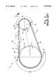
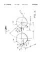
- an exemplary ISO-606 compliant roller chain drive system 10rotates in a clockwise direction as shown by arrow 11.
- the chain drive system 10includes a drive sprocket 12, a driven sprocket 14 and a roller chain 16 having a number of rollers 18.
- the sprockets 12, 14, and chain 16each generally comply with the ISO-606 standard.
- the roller chain 16engages and wraps about sprockets 12 and 14 and has two spans extending between the sprockets, slack strand 20 and taut strand 22.
- the roller chain 16is under tension as shown by arrows 24.
- the taut strand 22may be guided from the driven sprocket 14 to the drive sprocket 12 with a chain guide 26.
- a first roller 28is shown at the onset of meshing at a 12 o'clock position on the drive sprocket 12.
- a second roller 30is adjacent to the first roller 28 and is the next roller to mesh with the drive sprocket 12.
- Chain drive systemshave several components of undesirable noise.
- a major source of roller chain drive noiseis the sound generated as a roller leaves the span and collides with the sprocket during meshing.
- the resultant impact noiseis repeated with a frequency generally equal to that of the frequency of the chain meshing with the sprocket.
- the loudness of the impact noiseis a function of the impact energy (EA) occurring during the meshing process.
- the magnitude of the impact energyis related to engine speed, chain mass, and the impact velocity between the chain and the sprocket at the onset of meshing.
- the impact energy equationpresumes the chain drive kinematics will conform generally to a quasi-static analytical model and that the roller-sprocket driving contact will occur at a tangency point TP (FIG.3) for the flank and root radii as the sprocket collects a roller from the span.
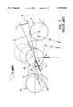
- the pressure angle ⁇is defined as the angle between a line A extending from the center of the engaging roller 25, when it is contacting the engaging tooth flank at the tangency point TP, through the center of the flank radius R f , and a line B connecting the centers of the fully seated roller 28, when it is seated on root diameter D 2 , and the center of the next meshing roller 30 as if it were also seated on root diameter D 2 in its engaging tooth space.
- the roller seating angles a and pressure angles ⁇ listed in Table 1are calculated from the equations defined above. It should be appreciated that ⁇ is a minimum when ⁇ is a maximum.
- the exemplary 18-tooth ISO compliant sprocket 12 of FIG. 3will have a pressure angle ⁇ in the range of 12.5° to 22.5° as shown in Table 1.
- FIG. 3also shows the engagement path (phantom rollers) and the meshing contact position of roller 30 (solid) as the drive sprocket 12 rotates in the direction of arrow 11. It is assumed that the chain drive kinematics generally conform to, and can be represented by a quasi-static analytical model, and that the drive contact occurs at the tangency point TP.
- FIG. 3depicts the theoretical case with chain roller 28 seated on root diameter D 2 of a maximum material sprocket with both chain pitch and sprocket chordal pitch equal to theoretical pitch P.
- the noise occurring at the onset of roller engagementhas a radial component F Ir as a result of roller 28 colliding with the root surface R i and a tangential component F Ir generated as the same roller 28 collides with the engaging tooth flank at point TP as the roller moves into driving contact. It is believed that the radial impact occurs first, with the tangential impact following nearly simultaneously. Roller impact velocity V A is shown to act through, and is substantially normal to, engaging flank tangent point TP with roller 28 in driving contact at point TP.
- the impact energy (E A ) equationaccounts only for a tangential roller impact during meshing.
- the actual roller engagementpresumed to have tangential and radial impacts (occurring in any order), would therefore seem to be at variance with the impact energy (E A ) equation.
- the application of this quasi-static modelwhich is beneficially used as a directional tool, permits an analysis of those features that may be modified to reduce the impact energy occurring during the tangential roller-sprocket collision at the onset of meshing.
- the radial collision during meshing, and its effect on the meshing noise levelscan be evaluated apart from the impact energy (E A ) equation.
- Another source of chain drive noiseis the broadband mechanical noise generated in part by shaft torsional vibrations and slight dimensional inaccuracies between the chain and the sprockets. Contributing to a greater extent to the broadband mechanical noise level is the intermittent or vibrating contact that occurs between an unloaded roller and the sprocket as the roller travels around the sprocket wrap.
- ordinary chain drive system wearcomprises sprocket tooth face wear and chain wear. The chain wear is caused by bearing wear in the chain joints and can be characterized as pitch elongation. It is believed that a worn chain meshing with an ISO standard sprocket will have only one roller in driving contact and loaded at a maximum loading condition.
- driving contact at maximum loadingoccurs as a roller enters a drive sprocket wrap 32 at engagement.
- Engaging roller 28is shown in driving contact and loaded at a maximum loading condition.
- the loading on roller 28is primarily meshing impact loading and the chain tension loading.
- the next several rollers in the wrap 32 forward of roller 28share in the chain tension loading, but at a progressively decreasing rate.
- the loading of roller 28(and to a lesser extent for the next several rollers in the wrap) serves to maintain the roller in solid or hard contact with the sprocket root surface 34.
- a roller 36is the last roller in the drive sprocket wrap 32 prior to entering the slack strand 20. Roller 36 is also in hard contact with drive sprocket 12, but at some point higher up (e.g., radially outwardly) on the root surface 34. With the exception of rollers 28 and 36, and the several rollers forward of roller 28 that share the chain tension loading, the remaining rollers in the drive sprocket wrap 32 are not in hard contact with the sprocket root surface 34, and are therefore free to vibrate against the sprocket root surfaces as they travel around the wrap, thereby contributing to the generation of unwanted broadband mechanical noise.
- a roller 38is the last roller in a sprocket wrap 40 of the driven sprocket 14 before entering the taut strand 22.
- the roller 38is in driving contact with the sprocket 14.
- a roller 42 in the sprocket wrap 40is in hard contact with a root radius 44 of driven sprocket 14, but generally not at the root diameter.
- pitch line clearance(PLC) between sprocket teeth promotes hard contact between the chain rollers and sprocket in the sprocket wrap as the roller chain wears.
- the amount of pitch line clearance added to the tooth spacedefines a length of a short arc that is centered in the tooth space and forms a segment of the root diameter D 2 .
- the root fillet radius R iis tangent to the flank radius R f and the root diameter arc segment.
- the tooth profileis still symmetrical, but R i is no longer a continuous fillet radius from one flank radius to the adjacent flank radius. This has the effect of reducing the broadband mechanical noise component of a chain drive system.
- adding pitch line clearance between sprocket teethdoes not reduce chain drive noise caused by the roller-sprocket collision at engagement.
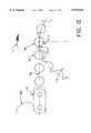
- Chordal actionis another important factor affecting the operating smoothness and noise levels of a chain drive, particularly at high speeds. Chordal action occurs as the chain enters the sprocket from the free span during meshing and it can cause a movement of the free chain in a direction perpendicular to the chain travel but in the same plane as the chain and sprockets. This chain motion resulting from chordal action will contribute an objectionable noise level component to the meshing noise levels, so it is therefore beneficial to reduce chordal action inherent in a roller chain drive.
- FIGS. 4a and 4billustrate the chordal action for an 18-tooth, ISO-606 compliant sprocket having a chordal pitch of 9.525 mm.
- Chordal rise 45may conventionally be defined as the displacement of the chain centerline as the sprocket rotates through an angle A/2, where:
- r cis the chordal radius, or the distance from the sprocket center to a pitch chord of length P; r p is the actual theoretical pitch radius; and Z is the number of sprocket teeth.
- FIGS. 4a and 4bshow only the drive sprocket 12 and assume a driven sprocket (not shown) also having 18-teeth and in phase with the drive sprocket shown.
- both sprocketssubstantially identical will have a tooth center at the 12 o'clock position.
- this chain drive arrangementunder quasi-static conditions will have a top or taut strand that will move up and down in a uniform manner a distance equal to that of the chordal rise.
- roller 46is at the onset of meshing, with chordal pitch P horizontal and in line with taut strand 22.
- the chain guide 26(FIG. 2) has the primary purpose to control chain strand vibration in the taut span.
- the geometry of the guide-chain interfacealso defines the length of unsupported chain over which chordal rise and fall is allowed to articulate.
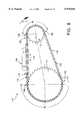
- FIG. 5is an enlarged view of FIG. 2 showing the first roller 28 at the onset of engagement and a second roller 30 as the next roller about to mesh with sprocket 12.
- the chain guide 26controls and guides the taut strand 22 except for five (5) unsupported link pitches extending between the chain guide 26 and the engaging roller 28.
- the taut strand 22is horizontal when the roller 28 is at the 12 o'clock position.
- the drive sprocket 12is rotated in a clockwise direction to advance roller 28 to a new angular position (A/2)+ ⁇ , determined by the instant of sprocket engagement of roller 30.
- Roller 28is considered to be seated and in hard contact with the root surface at D 2 at the onset of meshing of roller 30.
- a straight lineis assumed for the chain span from roller 28 to a chain pin center 48, about which the unsupported span from pin 48 to engaging roller 30 is considered to rotate.
- the location and chain-interfacing contour of the chain guide 26will determine the number of free span pitches about which articulation will take place as a result of the chordal rise and fall during the roller meshing process.
- chordal riseis the perpendicular displacement of the center of roller 30 (located on the pitch diameter PD) from the taut span 22 path as it moves from its initial meshing position shown to the 12 o'clock position.
- a roller chain sprocketin accordance with one aspect of the present invention, includes a first plurality of sprocket teeth each having a first tooth profile including a first engaging flank with a first contact point at which a roller initially contacts the first engaging flank, a second plurality of sprocket teeth each having a second tooth profile including a second engaging flank with a second contact point at which a roller initially contacts the second engaging flank; and the first tooth profile including a flank flat on the first engaging flank which facilitates spacing the first contact point on the first engaging flank relative to the second contact point on the second engaging flank to alter an initial roller-to-first engaging flank contact relative to an initial roller-to-second engaging flank contact.
- flank flatfacilitates altering the meshing contact from the first profile to the second. That is, while the frequency of the contacts (at constant rpm) will be substantially identical for each tooth profile, the profile differences serve to shift the initial contact phasing, thereby altering the rhythm of the initial contacts from one profile to the other.
- a unidirectional roller chain drive systemincludes a driving sprocket having sprocket teeth with engaging flanks and coast flanks, the engaging flanks cooperating with the coast flanks of adjacent teeth to define asymmetrical tooth spaces between the sprocket teeth, a driven sprocket having sprocket teeth with engaging flanks and coast flanks, the engaging flanks cooperating with the coast flanks of adjacent teeth to define asymmetrical tooth spaces between the sprocket teeth, a roller chain having rollers in engaging contact with the driving sprocket and the driven sprocket, and at least one of the driving sprocket and the driven sprocket including a first plurality of sprocket teeth each having a first engaging flank with a first contact point at which a roller initially contacts the first engaging flank, a second plurality of sprocket teeth each having a second engaging flank with a second contact point at which
- a roller chain sprocketin accordance with yet another aspect of the present invention, includes a first plurality of sprocket teeth each having a first engaging flank with a first contact point at which a roller initially contacts the first engaging flank, a second plurality of sprocket teeth each having a second engaging flank with a second contact point at which a roller initially contacts the second engaging flank, and the first engaging flank including a flank flat which facilitates phasing a frequency of initial roller-to-first engaging flank contacts relative to initial roller-to-second engaging flank contacts to alter the rhythm of the initial roller-to-first engaging flank and the roller-to-second engaging flank contacts.
- One advantage of the present inventionis the provision of a roller chain sprocket which incorporates a flank flat on an engaging tooth surface which facilitates altering a meshing contact from a first tooth profile to a second tooth profile.
- Another advantage of the present inventionis the provision of a roller chain sprocket which incorporates a flank flat on an engaging tooth surface which effects a time delay between an initial roller-to first sprocket tooth profile contact and an initial roller-to-second sprocket tooth profile contact.
- Another advantage of the present inventionis the provision of a roller chain sprocket which incorporates a flank flat on an engaging tooth surface of a first tooth profile which facilitates phasing a frequency of initial roller-to-engaging flank contacts of the first tooth profile relative to initial roller-to-engaging flank contacts of a second tooth profile to alter the rhythm of the initial roller-to-first engaging flank and the roller-to-second engaging flank contacts.
- Another advantage of the present inventionis the provision of a roller chain sprocket which incorporates added pitch mismatch between the sprocket and roller chain to facilitate a "staged" roller-to-sprocket impact.
- Still another advantage of the present inventionis the provision of a roller chain sprocket which incorporates an inclined root surface on an engaging flank, a coast flank, or both an engaging flank and a coast flank to provide tooth space clearance.
- Yet another advantage of the present inventionis the provision of a roller chain sprocket which minimizes impact noise generated by a roller-sprocket collision during meshing.
- a further advantage of the present inventionis the provision of a roller chain sprocket which minimizes broadband mechanical noise generated by unloaded rollers in a sprocket wrap.
- a still further advantage of the present inventionis the provision of a roller chain sprocket which provides a. "staged" roller impact wherein a tangential impact at full mesh occurs first followed by a radial impact.
- Yet a further advantage of the present inventionis the provision of a roller chain sprocket which spreads roller engagement over a significant time interval to provide for a more gradual load transfer, thereby minimizing roller-sprocket impact and the inherent noise generated therefrom.
- Yet a further advantage of the present inventionis the provision of a roller chain sprocket having two sets of sprocket teeth incorporating different tooth profiles which cooperate to reduce chain drive system noise levels below a noise level which either tooth profile used alone would produce.
- the inventionmay take form in various components and arrangements of components, and in various steps and arrangements of steps.
- the drawingsare only for purposes of illustrating a preferred embodiment and are not to be construed as limiting the invention.
- FIG. 1illustrates a symmetrical tooth space form for an ISO-606 compliant roller chain sprocket
- FIG. 2is an exemplary roller chain drive system having a ISO-606 compliant drive sprocket, driven sprocket, and roller chain;
- FIG. 3shows an engagement path (phantom) and a roller (solid) in a driving position as an ISO-606 compliant drive sprocket rotates in a clockwise direction;
- FIG. 4ashows a roller at the onset of meshing with an exemplary 18-tooth sprocket
- FIG. 4bshows the drive sprocket of FIG. 4a rotated in a clockwise direction until the roller is at a 12 o'clock position
- FIG. 5is an enlarged view of the drive sprocket of FIG. 2 with a roller fully seated in a tooth space and a second roller about to mesh with the drive sprocket;
- FIG. 6shows the drive sprocket of FIG. 5 rotated in a clockwise direction until the second roller initially contacts the drive sprocket;
- FIG. 7is an enlarged view of FIG. 6 showing that the second roller initially contacts a root surface (i.e., radial impact) of the drive sprocket, under theoretical conditions;
- FIG. 8illustrates a roller chain drive system having a roller chain drive sprocket and driven sprocket which incorporate the features of the present invention therein;
- FIG. 9illustrates the roller chain drive sprocket of FIG. 8 with an asymmetrical tooth space form in accordance with a first embodiment of the present invention
- FIG. 10is an enlarged view of the asymmetrical tooth space form of FIG. 9 showing a roller in two-point contact with the sprocket;
- FIG. 11shows an engagement path (phantom) and the full mesh position (solid) of a roller as the drive sprocket of FIG. 8 rotates in a clockwise direction;
- FIG. 12is an enlarged view of the drive sprocket of FIG. 8 with a roller fully seated in a tooth space and a second roller as the next roller to be collected from a taut span of the roller chain;
- FIG. 13shows the drive sprocket of FIG. 12 rotated in a clockwise direction until the second roller initially contacts the drive sprocket;
- FIG. 14is an enlarged view of FIG. 13 showing the first roller in two-point contact and second roller at initial tangential contact with the drive sprocket;
- FIG. 14aillustrates the progression of a first and a second roller as the roller chain drive sprocket of FIG. 8 is rotated in a clockwise direction;
- FIG. 14bis an enlarged view of the drive sprocket of FIG. 14 rotated in a clockwise direction to advance the second roller to the instant of full mesh at a 12 o'clock position;
- FIG. 15illustrates a roller chain drive sprocket with an asymmetrical tooth space form in accordance with a second embodiment of the present invention
- FIG. 16is an enlarged view of FIG. 8, showing the contact progression as the rollers travel around the drive sprocket wrap;
- FIG. 17is an enlarged view of a roller exiting a sprocket wrap of the sprocket of FIG. 8;
- FIG. 18illustrates a roller chain sprocket with an asymmetrical tooth space form in accordance with a third embodiment of the present invention
- FIG. 19illustrates a roller chain sprocket with an asymmetrical tooth space form in accordance with a fourth embodiment of the present invention
- FIG. 20is a side view of an exemplary random-engagement roller chain sprocket which incorporates the features of the present invention therein;
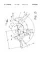
- FIG. 21illustrates the random-engagement roller chain sprocket of FIG. 20 with an additional asymmetrical tooth space form in accordance with the present invention
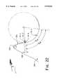
- FIG. 22illustrates the asymmetrical tooth space form of FIG. 9 overlaid with one embodiment of the asymmetrical tooth space form of FIG. 21;
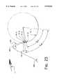
- FIG. 23illustrates the asymmetrical tooth space form of FIG. 9 overlaid with a second embodiment of the asymmetrical tooth space form of FIG. 21;
- FIG. 24illustrates the progression of a first and a second roller as the random-engagement roller chain sprocket of FIG. 20 is rotated in a clockwise direction;
- FIG. 25illustrates the sprocket of FIG. 23 with a first roller in two-point contact, a second roller at initial tangential contact, and a third roller about to mesh with the drive sprocket;
- FIG. 26illustrates the sprocket of FIG. 25 rotated in a clockwise direction until the instant of initial tangential contact between the third roller and the roller chain drive sprocket;
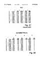
- FIG. 27is a table listing roller seating angles ( ⁇ ) and pressure angles ( ⁇ ) for a number of different ISO-606 compliant roller chain sprockets.
- FIG. 28is a table listing the maximum ( ⁇ ) angles and the corresponding minimum pressure angles ( ⁇ ) for three different asymmetrical tooth space profiles (1-3) of varying sprocket sizes.
- a roller chain drive system 110includes a drive sprocket 112 and a driven sprocket 114 which incorporate the features of the present invention therein.
- the roller chain drive system 110further includes a roller chain 116 having a number of rollers 118 which engage and wrap about sprockets 112, 114.
- the roller chainrotates in a clockwise direction as shown by arrow 11.
- the roller chain 116has two spans extending between the sprockets, slack strand 120 and taut strand 122.
- the roller chain 116is under tension as shown by arrows 124.
- a central portion of the taut strand 122may be guided from the driven sprocket 114 to the drive sprocket 112 with a chain guide 126.
- a first roller 128is shown fully seated at a 12 o'clock position on the drive sprocket 112.
- a second roller 130is adjacent to the first roller 128 and is about to mesh with the drive sprocket 112.
- asymmetrical tooth profile of the present inventionreference will be made only to the drive sprocket 112.
- the asymmetrical tooth profile of the present inventionis equally applicable to the driven sprocket 114, as well as to idler sprockets and sprockets associated with counter rotating balance shafts.
- the sprocket 112includes a first tooth 132 having an engaging flank 134, and a second tooth 136 having a coast or disengaging flank 138.
- the engaging flank 134 and coast flank 138cooperate to define a tooth space 140 which receives the engaging roller 128 (shown in phantom).
- the engaging roller 128has a roller diameter D 1 , and is shown fully seated in two-point contact within the tooth space 140 as described further below. More particularly, the engaging roller 128, when fully seated in the tooth space, contacts two lines B and C that extend axially along each sprocket tooth surface (i.e., in a direction orthogonal to the plane of the drawings). However, to facilitate a description thereof, the lines A, B, and C are hereafter shown and referred to as contact points within the tooth space.
- the engaging flankhas a radius R f which is tangent to a radially outer end of a flank flat 144.
- the location of the flank flat 144is defined by an angle ⁇ , with the flat orientation being normal or perpendicular to a line that passes through Point B and the center of roller 128 when the roller is contacting the sprocket at Points B and C.
- the length of the flank flat extending radially outward from Point Baffects a time delay between an initial tangential impact between sprocket 112 and roller 128 at a first contact Point A along the flank flat 144, and a subsequent radial impact at Point C.
- rollerstays in contact with the flank flat from its initial tangential contact at Point A until the roller moves to a fully engaged two-point contact position at Points B and C.
- the pressure angle ⁇ , the amount of pitch mismatch between the chain and the sprocket, and the length of the flank flatcan be varied to achieve a desired initial roller contact Point A at the onset of roller-sprocket meshing.
- flank (tangential) contactalways occurs first, with radial contact then occurring always at Point C regardless of chain pitch length.
- known tooth space formse.g., ISO compliant and asymmetrical
- single point contacte.g. single line contact
- an engaging rollermust move to a driving position after making radial contact. The pressure angles ⁇ therefore assume that the engaging roller will contact at the flank radius/root radius tangency point.
- the meshing contact location of the known single point/line tooth space formsis pitch "sensitive" to determine where the radial impact as well as tangential impact will occur.
- the engaging flank roller seating angle ⁇(FIG. 9) and a disengaging flank roller seating angle ⁇ ' replace the ISO-606 roller seating angle ⁇ (ISO profile shown in phantom).
- the pressure angle ⁇is a function of the engaging flank roller seating angle ⁇ . That is, as ⁇ increases, ⁇ decreases.
- a minimum asymmetrical pressure anglecan be determined from the following equation, where:
- FIG. 26lists the maximum Beta ( ⁇ ) angles and the corresponding minimum pressure angles ( ⁇ ) for several sprocket sizes and several asymmetrical profiles. It should be appreciated that reducing the engaging flank pressure angle ⁇ reduces the tangential impact force component F IA (FIG. 14) and thus the tangential impact noise contribution to the overall noise level at the onset of engagement.
- Impact force F IAis a function of the impact velocity which in turn is related to pressure angle ⁇ .
- pressure angle ⁇As pressure angle ⁇ is reduced, it provides a corresponding reduction in the impact velocity between the chain and the sprocket at the onset of meshing.
- a minimum pressure angle ⁇also facilitates a greater separation or distance between tangential contact points A and B to further increase or maximize engagement "staging".
- the engaging flank pressure angle ⁇is in the range of about -2.0° to about +5° to optimize the staged impact between the roller and the sprocket.
- roller seating angle ⁇is greater than ISO ⁇ max /2 at a maximum material condition and ⁇ can be adjusted until a desired engaging flank pressure angle ⁇ is achieved.
- the roller seating angle ⁇ of FIG. 9provides a pressure angle ⁇ that is less than zero, or a negative value.
- the negative pressure angle ⁇is best seen in FIG. 11, as contrasted with the ISO-606 compliant tooth profile of FIG. 3 with a positive pressure angle ⁇ . As shown in FIG.
- the asymmetrical profile pressure angle ⁇is defined as the angle between a line A extending from the center of the fully engaged roller 128, when it is contacting the engaging tooth flank at points B and C, through point B, and a line B connecting the centers of the fully seated roller 128, and the center of the next meshing roller 130 as if it were also two-point seated at full mesh in its engaging tooth space.
- a small negative pressure angle for the theoretical chain/sprocket interfacebeneficially provides a pressure angle ⁇ closer to zero (0) for a "nominal" system or for a system with wear.
- the engaging flank roller seating angle ⁇may be beneficially adjusted so as to provide any engaging flank pressure angle ⁇ having a value less than the minimum ISO-606 pressure angle.
- a first root radius R iis tangent to a radially inner end of the flank flat 144, and tangent to a radially outer end of an inclined root surface 146.
- a maximum root radius R imust be equal to, or less than, a minimum roller radius 0.5D 1 to facilitate the fully engaged two-point/line contact at Points B and C. Accordingly, this will define a small clearance 148 (FIG. 10) between the engaging flank 134 at root radius R i and roller 128 at full mesh (i.e., two-point/line contact).
- the flank flat 144 and the inclined root surface 146necessarily extend inside Points B and C respectively to facilitate the two-point/line roller contact at full engagement for all dimensional tolerance conditions of the roller 128 diameter (D 1 ) and the root radius R i .
- a second root radius R i 'is tangent to a radially inner end of the inclined root surface 146 at line 150.
- the coast flankhas a radius R f ' with its arc center defined by disengaging side roller seating angle ⁇ '.
- the inclined root surface 146is a flat surface having a finite length which defines a tooth space clearance (TSC).
- TSCtooth space clearance
- the tooth space clearancecompensates for chain pitch elongation or chain wear by accommodating a specified degree of chain pitch elongation ⁇ P.
- the tooth space clearance TSCenables rollers of a worn chain to be maintained in hard contact with the inclined root surface of the sprocket teeth.
- the inclined root surface 146facilitates reducing the radial reaction force thereby reducing the roller radial impact noise contribution to the overall noise level.
- the inclined root surface 146may be inclined at any angle ⁇ necessary to satisfy a specific chain drive geometry and chain pitch elongation. As shown in FIG. 9, the inclined root surface angle ⁇ is measured from a line 152 passing through the center of roller 128 and the sprocket center to a second line 154 which also passes through the center of roller 128 and Point C. The inclined root surface 146 is normal to the line 154, and the inclined root surface extends radially inward to line 150 where it is tangent to R i '. In the embodiment being described, the inclined root surface angle ⁇ is preferably in the range of about 20° to about 35°.
- FIG. 12is an enlarged view of FIG. 8 showing the first roller 128 at full engagement in two-point/line contact across the thickness or width of the sprocket tooth profile, and the second roller 130 as the next roller about to mesh with sprocket 112.
- the chain guide 126controls and guides a central portion the taut strand 122 except for five unsupported link pitches extending between the chain guide 126 and the engaging roller 128 (and except for the unsupported link pitches extending between the driven sprocket and the chain guide).
- the taut strand 122is horizontal when roller 128 is at the 12 o'clock position.
- FIG. 13shows the drive sprocket 112 rotated in a clockwise direction (A/2)+ ⁇ , as determined by the instant of sprocket engagement by roller 130.
- a straight lineis assumed for the chain span from roller 128 to a chain pin center 156, about which the unsupported span from pin center 156 to engaging roller 130 is considered to rotate. It should be appreciated that the straight line assumption is valid only in a quasi-static model. The amount of movement (or deviation from the straight line assumption) previously mentioned will be a function of the drive dynamics as well as the drive and sprocket geometry.
- the sprocket contact at the onset of mesh for roller 130occurs earlier than for the ISO counterpart, thereby reducing the amount of chordal rise and, just as importantly, allows the initial contact to beneficially occur at a desired pressure angle ⁇ on the engaging flank at Point A. Furthermore, the radial sprocket contact for roller 130, with its contribution to the overall noise level, does not occur until the sprocket rotation places roller 130 at the 12 o'clock position. This is referred to as staged engagement.
- FIG. 14an enlarged view of FIG. 13, more clearly shows the onset of meshing for roller 130.
- roller 128is assumed to carry the entire taut strand load F TB +F.sub. ⁇ , which load is shown as force vector arrows.
- the arrowsrepresent reaction forces to the taut strand chain force.
- a tangential impactoccurs as shown by impact force vector F IA .
- the tangential impactis not the same as the taut strand chain loading.
- impact loading or impact forceis related to the impact velocity V A . It is known that impact occurs during a collision between two bodies, resulting in relatively large forces over a comparatively short interval of time.
- a radial impact force vector F ICis shown only as an outline in that the radial impact does not occur until the sprocket has rotated sufficiently to place roller 130 at a 12 o'clock position.
- FIG. 14ashows the same roller positions (solid) for rollers 128 and 130 as shown in FIG. 14, but in addition, shows the roller positions (in phantom) relative to the sprocket profile once roller 130 reaches its two-point/line mesh at the 12 o'clock position.
- roller 128must move to a new position.
- roller 128progresses forward in its tooth space. Small clearances in the chain joints, however, reduce the amount of forward progression required for roller 128. Also occurring at the onset of meshing is the beginning of the taut strand load transfer from roller 128 to roller 130.
- the asymmetrical profileprovides for the previously described "staged" meshing.
- the Point A tangential contactoccurs at the onset of mesh, with its related impact force F IA .
- the roller 130is believed to stay in hard contact with the engaging flank 134 as the sprocket rotation moves the roller into full mesh with its resulting radial contact at Point C.
- the radial impact force F ICforce vector shown as an outline) does not occur until the sprocket has rotated sufficiently to bring roller 130 into radial contact at Point C.
- FIG. 14bis an enlarged view of FIG. 14, except that sprocket 112 has been rotated to advance roller 130 to the instant of full mesh at the 12 o'clock position.
- the radial impact force F ICoccurs and the taut strand load transfer is considered to be complete.
- the tangential impact force of F IAhas already occurred and is no longer a factor.
- the time delay ("staged" engagement) between the tangential and radial roller-sprocket collisionseffectively spreads the roller sprocket meshing impact energy over a greater time interval, thereby reducing its contribution to the generated noise level at mesh frequency.
- the present asymmetrical sprocket tooth profilebeneficially permits a more gradual taut strand load transfer from a fully engaged roller 128 to a meshing roller 130 as the meshing roller 130 moves from its Point A initial mesh to its full two-point mesh position.
- chordal rise (and fall) with the present asymmetrical profileis the perpendicular displacement of the center of roller 130 from the taut strand 122 path as it moves from its initial meshing contact Point A to the mesh position presently occupied by roller 128. It is believed that roller 130 will stay in hard contact with the engaging flank 134 as the roller moves from initial tangential contact to full mesh, and accordingly, the chordal rise is reduced as the distance between Points A and B is increased. As shown in FIG. 14, chain pitch P c is beneficially greater than sprocket 112 chordal pitch P s .
- the length of the inclined root surface 146may be reduced to zero (0), thereby eliminating the inclined root surface 146 and permitting root radius R i ' to be tangent to the root surface and the roller 142 at Point C. That is, R i ' is tangent to a short flat at Point C, and the flat is tangent to R i .
- the engaging flank pressure angle ⁇would generally be in the range of some positive value to zero, but normally not less than zero. The reason is that a negative ⁇ requires chordal pitch reduction so that the roller 60 can exit the sprocket wrap 60 (see FIGS. 16 and 17) without interfering with R f .
- FIG. 16shows the roller contact to the sprocket 112 profile for all the rollers in the wrap 60.
- Roller 128is in full two-point mesh as shown.
- Line 160shows the contact point for each of the rollers, as well as the contact progression as the rollers travel around the wrap.
- the inherent pitch mismatch between the sprocket and roller chaincauses the rollers to climb up the coast side flank as the rollers progress around the sprocket wrap. With the addition of appreciable chordal pitch reduction, the extent to which the rollers climb up the coast side flank in increased.
- chordal pitch reductionis required when the pressure angle ⁇ has a negative value. Otherwise, as shown in FIGS. 16 and 17, roller 162 would interfere with the engaging flank (with a maximum material sprocket and a theoretical pitch [shortest] chain) as it exits the wrap 60 back into the span. Also, the reduced chordal pitch assists the staged mesh as previously mentioned.
- FIG. 16 showing the roller contact progression in the wrap 60serves also to show why the shallow ⁇ ' angle and tooth space clearance TSC helps maintain "hard" roller-sprocket contact for the rollers in the wrap.
- disengaging flank roller seating angle ⁇ '(FIG. 9) may be adjusted to have a maximum value which is equal to ⁇ min /2 or even less.
- This reduced seating angle ⁇ 'promotes faster separation when the roller leaves the sprocket and enters the span.
- This reduced angle ⁇ 'also allows for the roller in a worn chain to ride up the coast flank surface to a less severe angle as the roller moves around the sprocket in the wrap. Accordingly, chordal pitch reduction, if used in this embodiment, should be a small value.
- asymmetrical tooth profile featurescan be altered without substantially deviating from the chain and sprocket meshing kinematics that produce the noise reduction advantages of the present invention.
- the engaging asymmetrical flank profilecould be approximated by an involute form
- the disengaging asymmetrical flank profilecould be approximated by a different involute form.
- Slight changes to the asymmetrical tooth profilesmay be made for manufacturing and/or quality control reasons, or simply to improve part dimensioning. These changes are within the scope of the invention as disclosed herein.
- the engaging flank inclined root surface 146may be replaced with a coast flank inclined root surface 164 as shown in FIG. 18.
- the coast flank inclined root surface 164provides tooth space clearance (TSC) in the same manner as described above with regard to the inclined root surface 146.
- TSCtooth space clearance
- the disengaging flank inclined root surface 164beneficially moves the roller to a preferred radially outward position as the chain wears.
- the disengaging flank inclined root surface 164may be included with the engaging flank inclined root surface 146 as shown in FIG. 19.
- the engaging flank and disengaging flank inclined root surfaces 146, 164cooperate to provide tooth space clearance (TSC) in the same manner as previously described.
- any one of the above-described asymmetrical tooth profile embodiments of FIGS. 9, 15, 18, and 19may be incorporated into a random-engagement roller chain sprocket 300.
- the sprocket 300is shown as an 18-tooth sprocket. However, the sprocket 300 may have more or less teeth, as desired.
- the sprocket 300includes a first group of arbitrarily positioned sprocket teeth 302 each having a profile which incorporates the flank flat 144 shown in FIGS. 9, 15, 18 and 19.
- the sprocket teeth 302may equally incorporate the tooth profiles shown in FIGS. 18 and 19.
- the remaining sprocket teeth 304(sprocket teeth 1, 3, 4, 9, 13, 14, and 16) are randomly positioned around the sprocket and incorporate a tooth profile different from that of the first group of sprocket teeth 302.
- the first and second groups of sprocket teeth 302, 304cooperate to reduce chain drive system noise levels below a noise level which either tooth profile used alone would produce.
- FIG. 21illustrates an exemplary tooth profile for one of the sprocket teeth 304.
- An engaging flank 306 and a coast or disengaging flank 308 of an adjacent toothcooperate to define a tooth space 310 which receives an engaging roller 314 (shown in phantom).
- the engaging roller 314has a roller diameter D I , and is shown fully seated in two-point contact within the tooth space 310.
- the engaging roller 314initially contacts the engaging flank 306 at point A' before fully seating in the tooth space at points B' and C.
- Contact points B' and Care actually lines that extend axially along each sprocket tooth surface (i.e., in a direction orthogonal to the plane of the drawings).
- the engaging flank 306has a radius R f which is tangent to a flat surface (not shown) at contact point B'.
- the flat surfacewhich functions only to facilitate the two-point roller contact (described further below), is normal to the roller 314 at point B'.
- the flatextends radially inward from point B' and is tangent to a first root radius R i .
- the first root radius R imay be tangent to a radially outer end of an inclined root surface 316.
- a maximum root radius R imust be equal to, or less than, a minimum roller radius to facilitate the fully engaged two-point/line contact at points B' and C.
- a small clearanceis defined between the root radius R i and the roller 314 when the roller 314 is fully seated at points B' and C.
- the flat surface and the inclined root surface 316necessarily extend inside contact points B' and C, respectively, to facilitate the two-point/line roller contact at engagement.
- a second root radius R i 'is tangent to a radially inner end of the inclined root surface 316 at line 318.
- the disengaging flankhas a radius R f ' at a point defined by the roller seating angle ⁇ '.
- the inclined root surface 316is a flat surface having a finite length which defines a tooth space clearance (TSC).
- TSCtooth space clearance
- the tooth space clearancecompensates for chain pitch elongation or chain wear by accommodating a specified degree of chain pitch elongation.
- the tooth space clearance TSCenables rollers of a worn chain to be maintained in hard contact with the inclined root surface of the sprocket teeth.
- the inclined root surface 316facilitates reducing the radial reaction force thereby reducing the roller radial impact noise contribution to the overall noise level.
- the inclined root surface 316may be inclined at any angle ⁇ necessary to satisfy a specific chain drive geometry and chain pitch elongation.
- the inclined root surface angle ⁇is measured from a line 320 passing through the center of roller 314 and the sprocket center to a second line 322 which also passes through the center of roller 314 and through contact point C.
- the inclined root surface 316is normal to the line 322, and the inclined root surface extends radially inward to line 318 where it is tangent to R i '.
- the inclined root surface angle ⁇is preferably in the range of about 20° to about 35°
- the tooth profile for the sprocket teeth 304may be substantially the same as the tooth profile shown in FIGS. 9 and 15 except that the tooth profile 304 does not have an engaging flank flat extending above (i.e. radially outward of) contact point B'.
- the engaging flank inclined root surface 316may be replaced with a disengaging flank inclined root surface as in FIG. 18. That is, the tooth profile 304 may be substantially identical to the sprocket 112 shown in FIG. 18 from contact point C to the outer diameter of the disengaging flank 308.
- the disengaging flank inclined root surfaceprovides tooth space clearance (TSC) in the same manner as the inclined root surface 316.
- the coast flank inclined root surfacebeneficially moves the roller to a preferred radially outward position as the chain wears.
- the disengaging flank inclined root surfacemay be included with the engaging flank inclined root surface 316 as in FIG. 19.
- the tooth profile 304may be substantially identical to the sprocket 112 shown in FIG. 19 from contact point C to the outer diameter of the coast flank 138.
- Pitch mismatchis inherent in a chain/sprocket interface except at one condition--the theoretical condition which is defined as a chain at its shortest pitch (shortest being theoretical pitch) and a maximum material sprocket.
- This theoretical conditiontherefore defines one limit (zero, or no pitch mismatch) of the tolerance range of the pitch mismatch relationship of chain and sprocket.
- the other limitis defined when a longest "as built" chain is used with a sprocket at minimum material conditions--or in other words, a sprocket having a minimum profile. This limit produces the greatest amount of pitch mismatch.
- the pitch mismatch rangeis therefore determined by the part feature tolerances.
- Additional pitch mismatchmay be introduced to facilitate a greater time delay between tangential contact at point A (for tooth profile 302) and tangential contact at point A' (for tooth profile 304). That is, varying the time at which roller-to-sprocket contact occurs for each tooth profile 302, 304 results in reduced mesh frequency noise because the point and rhythm of the initial roller-to-sprocket contact is altered.
- the time delay between the roller-to-sprocket contact at points A and A'may be increased by increasing the mismatch between the chain pitch and sprocket pitch.
- Additional pitch mismatchmay also be introduced to facilitate a "staged" roller contact for each tooth profile 302, 304. That is, additional pitch mismatch increases the time delay between initial tangential contact and the fully seated radial contact for each tooth profile 302, 304. It should be appreciated that staged contact is greater for the tooth profile 302 than for the tooth profile 304 due to the flank flat 144 which causes initial contact to occur higher up on the engaging flank of the sprocket teeth 302.
- chordal pitch reductionis necessarily shorter than the chain pitch to facilitate the "staged" roller-tooth contact.
- chordal pitch reductionalso provides roller-to-flank clearance as the roller exits the sprocket wrap back into the strand.
- Added chordal pitch reduction, when used,is preferably in the range of 0.005-0.030 mm.
- each tooth profile 302, 304may be further assisted by providing sprocket tooth pressure angles ⁇ that are substantially less than the ISO standard. Pressure angles ⁇ equal to or very close to zero (0), or even negative pressure angles, are contemplated.
- FIG. 22illustrates one embodiment of a random engagement sprocket 330 wherein the tooth profiles 302, 304 have the same, or at least substantially the same, pressure angles ⁇ (thus, the profiles 302, 304 have the same or at least substantially the same roller seating angles ⁇ 302 and ⁇ 304 ).
- the pressure angle for both profiles 302, 304is zero or a positive value.
- ⁇ min for both profiles 302, 304may be 0°
- ⁇ max for both profiles 302, 304is equal to some value less that the ISO minimum pressure angle ⁇ .
- initial roller-to-sprocket contactoccurs at point A followed by subsequent radial contact at points B and C for the tooth profile 302 of sprocket 330.
- initial roller-to-sprocket contactoccurs at point A' followed by subsequent radial contact at points B and C for the tooth profile 304 of sprocket 330.
- the sprocket 330may, or may not incorporate additional chordal pitch reduction, and may, or may not incorporate tooth space clearance (TSC), as described above.
- a second embodiment of a random engagement sprocket 340is shown wherein the pressure angles ⁇ for the tooth profiles 302, 304 are different. That is, both pressure angles ⁇ are either a positive value or zero, but the pressure angle ⁇ for tooth profile 302 is smaller than the pressure angle ⁇ for tooth profile 304 (and the roller seating angle ⁇ 302 is greater than the roller seating angle ⁇ 304 ) Thus, ⁇ min may be equal to 0° for the tooth profile 302, ⁇ min may be equal to +4 ° for the tooth profile 304, and ⁇ max for both profiles 302, 304 will always be less than the ISO minimum pressure angle (the feature tolerance band or range for ⁇ min and ⁇ max is the same for both tooth profiles 302, 304).
- initial roller-to-sprocket contactoccurs at point A followed by subsequent radial contact at points B and C for the tooth profile 302 of sprocket 340.
- initial roller-to-sprocket contactoccurs at point A' followed by subsequent radial contact at points B' and C for the tooth profile 304 of sprocket 340.
- the sprocket 340may or may not incorporate additional chordal pitch reduction, and may or may not incorporate tooth space clearance (TSC), as desired.
- the pressure angle ⁇ min for the profile 302may always be a negative value, while the pressure angle ⁇ min for profile 304 may always be a positive value or zero.
- ⁇ minmay be equal to -30 for the tooth profile 302
- ⁇ minmay be equal to +3° for the tooth profile 304
- ⁇ max for both profiles 302, 304will always be less than the ISO minimum pressure angle.
- additional chordal pitch reductionwill always be included, however, tooth space clearance may or may not be included.
- FIG. 24shows the engagement path of a roller 342 fully seated in the sprocket tooth 302, and an engagement path of the roller 314 engaging the adjacent sprocket tooth 304 of the sprocket 340.
- the chain load transfer from roller 342 to roller 314begins, until at full engagement, roller 314 will substantially carry the full chain load.
- roller 342will progress forward in its tooth space. Small clearances in the chain joints, however, will reduce the amount of forward progression required for Roller 342. Since impact energy is reduced with this profile geometry, the load transfer is more gradual than with the standard ISO profile.
- the references l A and l B(in FIG. 24 serve to show the amount of "staging" for each profile from the initial contact to the two-point contact at full mesh.
- the reference l Aindicates the linear distance separating the initial contact point A from the contact point B for the profile 302
- the reference l Bindicates the linear distance separating the initial contact point A' from the contact point B' for the profile 304.
- the value l A -l Bis a measure of the initial (tangential) contact time delay from profile 304 to profile 302, which is illustrated further in FIGS. 25 and 26.
- the time delaybeneficially increases with chain wear for the embodiment incorporating different pressure angles (FIG. 23) in that the tooth profile 304 "falls away" faster than does the tooth profile 302.
- the delayincreases with increasing chain pitch or pitch mismatch.
- FIGS. 25 and 26illustrate the meshing delay between the tooth profiles 302, 304.
- the sprocket 340has a roller 344 fully-seated in two-point contact with a sprocket tooth incorporating the tooth profile 302.
- the roller 342is shown at the instant of initial tangential contact at point A of a second sprocket tooth also incorporating the tooth profile 302.
- the roller 314is the next roller in the span and will mesh with a sprocket tooth incorporating the tooth profile 304.
- the sprocket 340must rotate through an angle ⁇ for roller 342 to move from its initial contact position at point A to full mesh, seated in two-point contact with the tooth profile 302 at a 12 o'clock position.
- the sprocket 340is shown rotated in a clockwise direction until roller 314 is at the instant of initial tangential contact at point A' of the tooth profile 304.
- the sprocket 340must now rotate through a smaller angle ⁇ for roller 314 to fully seat in two-point contact with the tooth profile 304 at a 12 o'clock position. That is, the staged contact for the tooth profile 302 is greater than for the tooth profile 304 due to the flank flat 144 as well as the difference in engaging side roller seating angles ⁇ 302 and ⁇ 304 which cause initial contact to occur higher up on the engaging flank of the sprocket teeth 302.
- the sprocket 340must rotate through an additional angle ⁇ - ⁇ in order for the roller to fully seat.
- the two sets of tooth profiles 302, 304are arranged in a random pattern in order to modify the meshing impact frequency by altering the point and rhythm of initial roller-to-sprocket contact.
- the two sets of tooth profiles 302, 304could be arranged in many different random patterns.
- the two sets of tooth profiles 302, 304could be arranged in many regular patterns that would work equally as well.
- the arrangement of two sets of different tooth profiles on a sprocketprovides a means for breaking up the mesh frequency impact noise normally associated with and induced by a full complement of substantially identically shaped sprocket teeth.
- the mesh frequency noise reductionis achieved by altering the point and rhythm of initial roller-to-sprocket contact.
- crankshaft sprocketgenerally the smallest sprocket in the chain drive, is usually the major noise contributor.
- the typically larger driven camshaft sprocketwill also contribute to the generated noise levels, but generally to a lesser extent than the crankshaft sprocket.
- the driven sprocketparticularly if it is nearly the same size or smaller than the driving sprocket, may be the prime noise generator, as in the case with balance shaft sprockets and pump sprockets.
- the features of the present inventionmay also be used advantageously with camshaft or driven sprockets as well.
- tooth profile features of FIGS. 20-26can be altered slightly without substantially deviating from the chain and sprocket meshing kinematics that produce the noise reduction advantages of the present invention.
- the engaging asymmetrical flank profilecould be approximated by an involute form
- the disengaging asymmetrical flank profilecould be approximated by a different involute form. Slight changes to the profile may be done for manufacturing and/or quality control reasons --or simply to improve part dimensioning.
Landscapes
- Engineering & Computer Science (AREA)
- General Engineering & Computer Science (AREA)
- Mechanical Engineering (AREA)
- Gears, Cams (AREA)
- Devices For Conveying Motion By Means Of Endless Flexible Members (AREA)
Abstract
Description
α.sub.max =(140°-90°)/Z and α.sub.min =(120°-90°)/Z
Chordal rise=r.sub.p -r.sub.c =r.sub.p [1-cos(180°/Z)]
γ.sub.min =β.sub.max -(α.sub.max /2+γ.sub.ISO min)
Claims (25)
Priority Applications (7)
| Application Number | Priority Date | Filing Date | Title |
|---|---|---|---|
| EP97938040AEP0912844B1 (en) | 1996-07-25 | 1997-07-25 | Random engagement roller chain sprocket having improved noise characteristics |
| JP50899898AJP4107684B2 (en) | 1996-07-25 | 1997-07-25 | Roller chain sprocket and one-way roller chain drive system |
| CA002259391ACA2259391C (en) | 1996-07-25 | 1997-07-25 | Random engagement roller chain sprocket having improved noise characteristics |
| BR9710575-9ABR9710575A (en) | 1996-07-25 | 1997-07-25 | Roller chain sprocket, randomly coupled, with improved noise characteristics. |
| DE69715628TDE69715628T2 (en) | 1996-07-25 | 1997-07-25 | OPTIONALLY INTERRUPTING ROLLER CHAIN WHEEL WITH IMPROVED NOISE BEHAVIOR |
| US08/900,661US5976045A (en) | 1996-07-25 | 1997-07-25 | Random engagement roller chain sprocket having improved noise characteristics |
| US09/419,336US6090003A (en) | 1996-07-25 | 1999-10-15 | Random engagement roller chain sprocket having improved noise characteristics |
Applications Claiming Priority (3)
| Application Number | Priority Date | Filing Date | Title |
|---|---|---|---|
| US2232196P | 1996-07-25 | 1996-07-25 | |
| US3237996P | 1996-12-19 | 1996-12-19 | |
| US08/900,661US5976045A (en) | 1996-07-25 | 1997-07-25 | Random engagement roller chain sprocket having improved noise characteristics |
Related Child Applications (1)
| Application Number | Title | Priority Date | Filing Date |
|---|---|---|---|
| US09/419,336ContinuationUS6090003A (en) | 1996-07-25 | 1999-10-15 | Random engagement roller chain sprocket having improved noise characteristics |
Publications (1)
| Publication Number | Publication Date |
|---|---|
| US5976045Atrue US5976045A (en) | 1999-11-02 |
Family
ID=26695800
Family Applications (1)
| Application Number | Title | Priority Date | Filing Date |
|---|---|---|---|
| US08/900,661Expired - LifetimeUS5976045A (en) | 1996-07-25 | 1997-07-25 | Random engagement roller chain sprocket having improved noise characteristics |
Country Status (7)
| Country | Link |
|---|---|
| US (1) | US5976045A (en) |
| EP (1) | EP0912844B1 (en) |
| JP (1) | JP4107684B2 (en) |
| BR (1) | BR9710575A (en) |
| CA (1) | CA2259391C (en) |
| DE (1) | DE69715628T2 (en) |
| WO (1) | WO1998004848A2 (en) |
Cited By (27)
| Publication number | Priority date | Publication date | Assignee | Title |
|---|---|---|---|---|
| US6155943A (en)* | 1997-10-03 | 2000-12-05 | Borgwarner Inc. | Randomized sprocket for roller chain |
| US6364798B1 (en)* | 1997-09-30 | 2002-04-02 | Ford Global Technologies, Inc. | Sprocket for roller chain drives |
| US6375589B1 (en)* | 1999-02-03 | 2002-04-23 | Sankyo Oilless Industry | Roller chain sprocket |
| US6416436B1 (en)* | 1999-07-22 | 2002-07-09 | Tsubakimoto Chain Co. | Silent chain power transmitting device |
| US6415532B1 (en) | 2000-07-31 | 2002-07-09 | The Toro Company | Drive sprocket for a roller chain for material removal implement |
| US20020132689A1 (en)* | 1996-12-19 | 2002-09-19 | Young James D. | Roller chain sprocket with added chordal pitch reduction |
| US20030087714A1 (en)* | 2001-11-06 | 2003-05-08 | Borgwarner Inc. | Tension-reducing random sprocket |
| US6595603B2 (en)* | 2000-05-03 | 2003-07-22 | Demag Mobile Cranes Gmbh & Co. Kg | Drive sprocket wheel for a track vehicle |
| US6726293B2 (en)* | 2002-08-12 | 2004-04-27 | Caterpillar Inc | Tracked mobile machine with star carrier roller and method of assembly |
| WO2004059194A1 (en) | 2002-12-19 | 2004-07-15 | Cloyes Gear And Products, Inc. | Asymmetric sprocket assembly with metal cushion rings |
| US20040185977A1 (en)* | 1996-12-19 | 2004-09-23 | Cloyes Gear And Products, Inc. | Random engagement roller chain sprocket and timing chain system including same |
| US20060058141A1 (en)* | 2004-08-26 | 2006-03-16 | Cloyes Gear And Products, Inc. | Inverted tooth chain sprocket with frequency modulated meshing |
| US20060160648A1 (en)* | 2005-01-20 | 2006-07-20 | Borgwarner Inc. | Randomized chain system |
| CN100347469C (en)* | 2003-07-04 | 2007-11-07 | 株式会社椿本链索 | Sprocket for chain |
| US20080312017A1 (en)* | 2007-05-11 | 2008-12-18 | Young James D | Inverted tooth chain sprocket with frequency modulated meshing |
| US20100167857A1 (en)* | 2007-06-20 | 2010-07-01 | Borgwarner Inc. | Resonance tension reducing sprocket with combined radial variation and sprocket wrap |
| US20100227720A1 (en)* | 2008-03-06 | 2010-09-09 | Borgwarner Inc. | Sprocket randomization for enhanced nvh control |
| US20100292038A1 (en)* | 2007-09-28 | 2010-11-18 | Borgwarner Inc. | Multiple Tension Reducing Sprockets in a Chain and Sprocket System |
| US20110245002A1 (en)* | 2010-04-06 | 2011-10-06 | Cloyes Gear And Products, Inc. | Inverted tooth chain sprocket with frequency modulated meshing features |
| US20130345006A1 (en)* | 2012-06-21 | 2013-12-26 | Tai-Her Yang | Chainwheel Enabling Positive Rotational Transmission and Reverse Rotational Sliding Features |
| ITFE20130003A1 (en)* | 2013-04-05 | 2014-10-06 | Iesse Srls | TRACK WHEEL TRACK WHEEL TRACKS |
| US20170146109A1 (en)* | 2015-07-03 | 2017-05-25 | Sram Deutschland Gmbh | Sprocket wheel for a bicycle drive |
| US9885409B1 (en)* | 2016-09-12 | 2018-02-06 | Shimano Inc. | Bicycle sprocket and bicycle rear sprocket assembly |
| US20190084649A1 (en)* | 2017-09-15 | 2019-03-21 | Shimano Inc. | Bicycle sprocket |
| US10703441B2 (en) | 2015-07-03 | 2020-07-07 | Sram Deutschland Gmbh | Drive arrangement for a bicycle |
| US10907721B2 (en)* | 2015-12-09 | 2021-02-02 | Borgwarner Inc. | Non-prevalent order random sprocket |
| US11181179B2 (en)* | 2018-03-30 | 2021-11-23 | Tsubakimoto Chain Co. | Sprocket and drive mechanism |
Families Citing this family (6)
| Publication number | Priority date | Publication date | Assignee | Title |
|---|---|---|---|---|
| DE29621084U1 (en)* | 1996-12-04 | 1998-04-02 | Joh. Winklhofer & Söhne GmbH und Co KG, 81369 München | Sprocket |
| BR9909667A (en)* | 1998-03-26 | 2000-11-21 | Cloyes Gear & Products Inc | Random chain gear tooth coupling with stepped gear and root relief to provide improved noise characteristics |
| EP1235003A1 (en)* | 2001-02-23 | 2002-08-28 | Morse Tec Europe S.p.A. | Sprocket for a roller chain or bushing chain, with teeth having a different flank profile on the same sprocket |
| EP3251940B1 (en) | 2016-06-03 | 2018-12-19 | ZUMA Innovation, S.L. | Chain-ring set for a power transmission system |
| EP3251937A1 (en)* | 2016-06-03 | 2017-12-06 | ZUMA Innovation, S.L. | Chain-rings set for a bicycle power transmission system provided with segmented chain-ring |
| EP3251938A1 (en) | 2016-06-03 | 2017-12-06 | ZUMA Innovation, S.L. | Chain-rings set for a power transmission system provided with segmented chain-rings in different planes |
Citations (68)
| Publication number | Priority date | Publication date | Assignee | Title |
|---|---|---|---|---|
| US30018A (en)* | 1860-09-11 | Improvement in raking apparatus for harvesters | ||
| US320734A (en)* | 1885-06-23 | Belt-gearing | ||
| US536813A (en)* | 1895-04-02 | Sprocket-wheel | ||
| US698991A (en)* | 1901-04-13 | 1902-04-29 | Morse Chain Co | Chain-wheel. |
| US717976A (en)* | 1901-11-07 | 1903-01-06 | Link Belt Engineering Company | Sprocket-wheel for drive-chains. |
| US984509A (en)* | 1909-06-12 | 1911-02-14 | Sam A Crowder | Sprocket driving mechanism. |
| US1630313A (en)* | 1925-04-30 | 1927-05-31 | American Manganese Steel Co | Sprocket wheel |
| US1808369A (en)* | 1926-06-21 | 1931-06-02 | Celotex Company | Sprocket |
| US2382740A (en)* | 1943-07-10 | 1945-08-14 | Fred P Noffsinger | Sprocket wheel |
| US2934200A (en)* | 1956-10-15 | 1960-04-26 | Gen Motors Corp | Conveyor system |
| US3130791A (en)* | 1963-02-04 | 1964-04-28 | Lloyd K Schmidt | Endless chain drive unit |
| US3194609A (en)* | 1964-03-30 | 1965-07-13 | Thurlow Lloyd | Sprocket and chain drive |
| US3298406A (en)* | 1964-05-15 | 1967-01-17 | Herbert V Erickson | Chain saw chain |
| US3377875A (en)* | 1966-05-09 | 1968-04-16 | Gen Motors Corp | Chain drive power transmitting mechanism |
| US3448629A (en)* | 1968-06-20 | 1969-06-10 | Amsted Ind Inc | Chain and sprocket drive |
| US3495468A (en)* | 1968-11-21 | 1970-02-17 | Gen Motors Corp | Chain drive |
| US3604755A (en)* | 1969-07-24 | 1971-09-14 | Cincinnati Mine Machinery Co | Cutter bar, cutter chain and sprocket assembly |
| US3824869A (en)* | 1972-09-25 | 1974-07-23 | Standard Tool & Mfg Co | Chain drive having pivoted drive teeth |
| US3956943A (en)* | 1972-10-25 | 1976-05-18 | Maeda Industries, Ltd. | Bicycle sprocket wheel |
| US4016772A (en)* | 1975-09-22 | 1977-04-12 | Caterpillar Tractor Co. | Sprocket member configuration |
| US4036071A (en)* | 1976-04-02 | 1977-07-19 | Hollis And Company | Sprocket and method for producing same |
| US4089406A (en)* | 1974-10-09 | 1978-05-16 | Fritz Teske | Chain drive |
| US4099423A (en)* | 1977-06-21 | 1978-07-11 | Max Mullins | Compatible sprocket and chain system |
| US4116081A (en)* | 1977-05-25 | 1978-09-26 | Caterpillar Tractor Co. | Sprocket profile |
| US4168634A (en)* | 1977-05-27 | 1979-09-25 | General Motors Corporation | Chain and sprocket power transmitting mechanism |
| US4174642A (en)* | 1978-02-09 | 1979-11-20 | Gehl Company | Chain drive including sprocket having alternate wide and narrow teeth |
| US4181033A (en)* | 1976-12-28 | 1980-01-01 | Shimano Industrial Company Limited | Sprocket for bicycles |
| US4200000A (en)* | 1978-10-04 | 1980-04-29 | Societe Suisse Pour L'industrie Horlogere Management Services S.A. | Gear train |
| US4207777A (en)* | 1978-11-07 | 1980-06-17 | Societe Suisse pour l'Industrie Horlogere Mangagement Services S.A. | One way gear train |
| US4274184A (en)* | 1977-10-20 | 1981-06-23 | Svein Nordtvedt | Mesh distribution wheels |
| US4294132A (en)* | 1977-09-29 | 1981-10-13 | Fabryka Obrabiarek Precyzyjnych "Ponar-Bruszkow" | Cylindrical gear with helical teeth |
| US4342560A (en)* | 1980-05-16 | 1982-08-03 | Borg-Warner Corporation | Composite chain link assembly |
| US4378965A (en)* | 1979-02-28 | 1983-04-05 | Konishiroku Photo Industry Co., Ltd. | Sprocket wheel for photographic camera |
| US4401420A (en)* | 1979-09-14 | 1983-08-30 | Hitachi, Ltd. | Male and female screw rotor assembly with specific tooth flanks |
| US4492030A (en)* | 1981-08-24 | 1985-01-08 | Beerens Cornelis J | Chain saw bars |
| US4509323A (en)* | 1981-12-18 | 1985-04-09 | Borg-Warner Corporation | Power transmission chain |
| US4509937A (en)* | 1981-12-18 | 1985-04-09 | Borg-Warner Corporation | Power transmission chain |
| US4521207A (en)* | 1982-06-11 | 1985-06-04 | Royce H. Husted | Incrementally variable transmission |
| US4522611A (en)* | 1982-12-27 | 1985-06-11 | Esco Corporation | Sprocket assembly with replaceable teeth |
| US4531926A (en)* | 1983-07-11 | 1985-07-30 | Reeves Jr James B | Adjustable pitch sprocket |
| US4559028A (en)* | 1983-07-11 | 1985-12-17 | Reeves Jr James B | Adjustment pitch sprocket |
| US4571218A (en)* | 1983-07-11 | 1986-02-18 | Reeves Jr James B | Adjustable pitch sprocket |
| US4604080A (en)* | 1983-10-12 | 1986-08-05 | Mitsuboshi Belting Ltd. | Toothed drive belt |
| US4653340A (en)* | 1986-03-03 | 1987-03-31 | Pitney Bowes Inc. | Beveled spur gear |
| US4738653A (en)* | 1987-01-15 | 1988-04-19 | Deere & Company | Roller chain drive having a self cleaning roller chain sprocket |
| US4758209A (en)* | 1987-04-01 | 1988-07-19 | Borg-Warner Automotive, Inc. | Silent timing chain and sprocket system |
| US4758210A (en)* | 1987-04-01 | 1988-07-19 | Borg-Warner Automotive, Inc. | Silent chain and sprocket system |
| US4813916A (en)* | 1988-03-08 | 1989-03-21 | Sachs-Huret S.A. | Sprocket having teeth of improved shape and a cycle free-wheel including said sprocket |
| US4832668A (en)* | 1984-10-17 | 1989-05-23 | Borg-Warner Corporation | Power transmission chain |
| US4878886A (en)* | 1988-01-27 | 1989-11-07 | Bando Chemical Industries, Ltd. | Toothed belt and power transmission device using the same |
| US4889521A (en)* | 1987-10-21 | 1989-12-26 | Shimano Industrial Company Limited | Multistage sprocket assembly for a bicycle |
| US4911032A (en)* | 1988-10-03 | 1990-03-27 | Moore Push-Pin Company | One-way gear |
| US4915675A (en)* | 1989-02-28 | 1990-04-10 | Avramidis Stellios A | Pitch equalized chain with frequency modulated engagement |
| US4915604A (en)* | 1987-08-11 | 1990-04-10 | Hitachi, Ltd. | Rotors for a screw fluid machine |
| US4969371A (en)* | 1989-01-26 | 1990-11-13 | Renold, Inc. | Gear type flexible coupling |
| US5015218A (en)* | 1988-11-29 | 1991-05-14 | Pirelli Transmissioni Industriali S.P.A. | Toothed pulley and transmission related thereto |
| US5022280A (en)* | 1988-03-29 | 1991-06-11 | Boiko Leonid S | Novikov gearing |
| US5073151A (en)* | 1988-11-07 | 1991-12-17 | Shimano Industrial Co., Ltd. | Multi-speed sprocket assembly for bicycle |
| US5123878A (en)* | 1990-01-20 | 1992-06-23 | Shimano Industrial Company Limited | Multistage sprocket assembly |
| US5133695A (en)* | 1989-02-15 | 1992-07-28 | Maeda Industries, Ltd. | Bicycle multiple chainwheel |
| US5154674A (en)* | 1990-04-25 | 1992-10-13 | Borg-Warner Automotive Transmission & Engine Components Corporation | Power transmission chain constructed with asymmetrical links |
| US5162022A (en)* | 1990-09-18 | 1992-11-10 | Maeda Industries, Ltd. | Multiple sprocket assembly for bicycle |
| US5163826A (en)* | 1990-10-23 | 1992-11-17 | Cozens Eric E | Crescent gear pump with hypo cycloidal and epi cycloidal tooth shapes |
| US5318483A (en)* | 1993-05-14 | 1994-06-07 | American Longwall Face Conveyors, Inc. | Sprocket with asymmetrical teeth for mining conveyors |
| US5397278A (en)* | 1993-06-30 | 1995-03-14 | Tsubakimoto Chain Co. | Sprocket for roller chain |
| US5427580A (en)* | 1992-05-19 | 1995-06-27 | Borg-Warner Automotive, Inc. | Phased chain assemblies |
| US5437582A (en)* | 1993-06-03 | 1995-08-01 | Campagnolo S.R.L. | Sprocket assembly for bicycles |
| US5503598A (en)* | 1993-09-13 | 1996-04-02 | Fichtel & Sachs Ag | Derailleur arrangement, in particular for bicycles |
Family Cites Families (7)
| Publication number | Priority date | Publication date | Assignee | Title |
|---|---|---|---|---|
| DE166326C (en)* | ||||
| US2259937A (en)* | 1940-02-05 | 1941-10-21 | Chain Belt Co | Roller chain sprocket wheel |
| DE821303C (en)* | 1948-11-09 | 1951-11-15 | Heinrich Aumund Dr Ing | Chain transmission |
| CH413509A (en)* | 1964-08-13 | 1966-05-15 | Schweiz Wagons Aufzuegefab | Sprocket wheel |
| FR2325804A1 (en)* | 1975-09-26 | 1977-04-22 | Chrysler France | Chain drive for use in IC engine - has tooth contact faces machined to cause radial movement of chain rollers for wear take-up |
| DE4331482A1 (en)* | 1992-09-21 | 1994-03-24 | Luk Lamellen & Kupplungsbau | Chain or toothed belt drive for driving valves in IC engines - has irregular divisions on chain wheels interacting with different length chain links |
| US5514042A (en)* | 1995-08-01 | 1996-05-07 | Liou; Yan-Shing | Multistage sprocket mechanism for a bicycle |
- 1997
- 1997-07-25JPJP50899898Apatent/JP4107684B2/ennot_activeExpired - Fee Related
- 1997-07-25USUS08/900,661patent/US5976045A/ennot_activeExpired - Lifetime
- 1997-07-25EPEP97938040Apatent/EP0912844B1/ennot_activeExpired - Lifetime
- 1997-07-25DEDE69715628Tpatent/DE69715628T2/ennot_activeExpired - Lifetime
- 1997-07-25CACA002259391Apatent/CA2259391C/ennot_activeExpired - Lifetime
- 1997-07-25WOPCT/US1997/013076patent/WO1998004848A2/enactiveIP Right Grant
- 1997-07-25BRBR9710575-9Apatent/BR9710575A/ennot_activeIP Right Cessation
Patent Citations (73)
| Publication number | Priority date | Publication date | Assignee | Title |
|---|---|---|---|---|
| US30018A (en)* | 1860-09-11 | Improvement in raking apparatus for harvesters | ||
| US320734A (en)* | 1885-06-23 | Belt-gearing | ||
| US536813A (en)* | 1895-04-02 | Sprocket-wheel | ||
| US698991A (en)* | 1901-04-13 | 1902-04-29 | Morse Chain Co | Chain-wheel. |
| US717976A (en)* | 1901-11-07 | 1903-01-06 | Link Belt Engineering Company | Sprocket-wheel for drive-chains. |
| US984509A (en)* | 1909-06-12 | 1911-02-14 | Sam A Crowder | Sprocket driving mechanism. |
| US1630313A (en)* | 1925-04-30 | 1927-05-31 | American Manganese Steel Co | Sprocket wheel |
| US1808369A (en)* | 1926-06-21 | 1931-06-02 | Celotex Company | Sprocket |
| US2382740A (en)* | 1943-07-10 | 1945-08-14 | Fred P Noffsinger | Sprocket wheel |
| US2934200A (en)* | 1956-10-15 | 1960-04-26 | Gen Motors Corp | Conveyor system |
| US3130791A (en)* | 1963-02-04 | 1964-04-28 | Lloyd K Schmidt | Endless chain drive unit |
| US3194609A (en)* | 1964-03-30 | 1965-07-13 | Thurlow Lloyd | Sprocket and chain drive |
| US3298406A (en)* | 1964-05-15 | 1967-01-17 | Herbert V Erickson | Chain saw chain |
| US3377875A (en)* | 1966-05-09 | 1968-04-16 | Gen Motors Corp | Chain drive power transmitting mechanism |
| US3448629A (en)* | 1968-06-20 | 1969-06-10 | Amsted Ind Inc | Chain and sprocket drive |
| US3495468A (en)* | 1968-11-21 | 1970-02-17 | Gen Motors Corp | Chain drive |
| US3604755A (en)* | 1969-07-24 | 1971-09-14 | Cincinnati Mine Machinery Co | Cutter bar, cutter chain and sprocket assembly |
| US3824869A (en)* | 1972-09-25 | 1974-07-23 | Standard Tool & Mfg Co | Chain drive having pivoted drive teeth |
| US3956943A (en)* | 1972-10-25 | 1976-05-18 | Maeda Industries, Ltd. | Bicycle sprocket wheel |
| US4089406A (en)* | 1974-10-09 | 1978-05-16 | Fritz Teske | Chain drive |
| USRE30018E (en) | 1975-09-22 | 1979-06-05 | Caterpillar Tractor Co. | Sprocket member configuration |
| US4016772A (en)* | 1975-09-22 | 1977-04-12 | Caterpillar Tractor Co. | Sprocket member configuration |
| US4036071A (en)* | 1976-04-02 | 1977-07-19 | Hollis And Company | Sprocket and method for producing same |
| US4181033A (en)* | 1976-12-28 | 1980-01-01 | Shimano Industrial Company Limited | Sprocket for bicycles |
| US4116081A (en)* | 1977-05-25 | 1978-09-26 | Caterpillar Tractor Co. | Sprocket profile |
| US4168634A (en)* | 1977-05-27 | 1979-09-25 | General Motors Corporation | Chain and sprocket power transmitting mechanism |
| US4099423A (en)* | 1977-06-21 | 1978-07-11 | Max Mullins | Compatible sprocket and chain system |
| US4294132A (en)* | 1977-09-29 | 1981-10-13 | Fabryka Obrabiarek Precyzyjnych "Ponar-Bruszkow" | Cylindrical gear with helical teeth |
| US4274184A (en)* | 1977-10-20 | 1981-06-23 | Svein Nordtvedt | Mesh distribution wheels |
| US4174642A (en)* | 1978-02-09 | 1979-11-20 | Gehl Company | Chain drive including sprocket having alternate wide and narrow teeth |
| US4200000A (en)* | 1978-10-04 | 1980-04-29 | Societe Suisse Pour L'industrie Horlogere Management Services S.A. | Gear train |
| US4207777A (en)* | 1978-11-07 | 1980-06-17 | Societe Suisse pour l'Industrie Horlogere Mangagement Services S.A. | One way gear train |
| US4378965A (en)* | 1979-02-28 | 1983-04-05 | Konishiroku Photo Industry Co., Ltd. | Sprocket wheel for photographic camera |
| US4401420A (en)* | 1979-09-14 | 1983-08-30 | Hitachi, Ltd. | Male and female screw rotor assembly with specific tooth flanks |
| US4342560A (en)* | 1980-05-16 | 1982-08-03 | Borg-Warner Corporation | Composite chain link assembly |
| US4492030A (en)* | 1981-08-24 | 1985-01-08 | Beerens Cornelis J | Chain saw bars |
| US4509323A (en)* | 1981-12-18 | 1985-04-09 | Borg-Warner Corporation | Power transmission chain |
| US4509937A (en)* | 1981-12-18 | 1985-04-09 | Borg-Warner Corporation | Power transmission chain |
| US4521207A (en)* | 1982-06-11 | 1985-06-04 | Royce H. Husted | Incrementally variable transmission |
| US4522611A (en)* | 1982-12-27 | 1985-06-11 | Esco Corporation | Sprocket assembly with replaceable teeth |
| US4531926A (en)* | 1983-07-11 | 1985-07-30 | Reeves Jr James B | Adjustable pitch sprocket |
| US4559028A (en)* | 1983-07-11 | 1985-12-17 | Reeves Jr James B | Adjustment pitch sprocket |
| US4571218A (en)* | 1983-07-11 | 1986-02-18 | Reeves Jr James B | Adjustable pitch sprocket |
| US4604080A (en)* | 1983-10-12 | 1986-08-05 | Mitsuboshi Belting Ltd. | Toothed drive belt |
| US4832668A (en)* | 1984-10-17 | 1989-05-23 | Borg-Warner Corporation | Power transmission chain |
| US4653340A (en)* | 1986-03-03 | 1987-03-31 | Pitney Bowes Inc. | Beveled spur gear |
| US4738653A (en)* | 1987-01-15 | 1988-04-19 | Deere & Company | Roller chain drive having a self cleaning roller chain sprocket |
| US4758210A (en)* | 1987-04-01 | 1988-07-19 | Borg-Warner Automotive, Inc. | Silent chain and sprocket system |
| US4758209A (en)* | 1987-04-01 | 1988-07-19 | Borg-Warner Automotive, Inc. | Silent timing chain and sprocket system |
| US4915604A (en)* | 1987-08-11 | 1990-04-10 | Hitachi, Ltd. | Rotors for a screw fluid machine |
| US4889521A (en)* | 1987-10-21 | 1989-12-26 | Shimano Industrial Company Limited | Multistage sprocket assembly for a bicycle |
| US4889521B1 (en)* | 1987-10-21 | 1995-05-09 | Shimano Industrial Co | Multistage sprocket assembly for a bicycle |
| US4878886A (en)* | 1988-01-27 | 1989-11-07 | Bando Chemical Industries, Ltd. | Toothed belt and power transmission device using the same |
| US4813916A (en)* | 1988-03-08 | 1989-03-21 | Sachs-Huret S.A. | Sprocket having teeth of improved shape and a cycle free-wheel including said sprocket |
| US5022280A (en)* | 1988-03-29 | 1991-06-11 | Boiko Leonid S | Novikov gearing |
| US4911032A (en)* | 1988-10-03 | 1990-03-27 | Moore Push-Pin Company | One-way gear |
| US5073151A (en)* | 1988-11-07 | 1991-12-17 | Shimano Industrial Co., Ltd. | Multi-speed sprocket assembly for bicycle |
| US5015218A (en)* | 1988-11-29 | 1991-05-14 | Pirelli Transmissioni Industriali S.P.A. | Toothed pulley and transmission related thereto |
| US4969371A (en)* | 1989-01-26 | 1990-11-13 | Renold, Inc. | Gear type flexible coupling |
| US5133695A (en)* | 1989-02-15 | 1992-07-28 | Maeda Industries, Ltd. | Bicycle multiple chainwheel |
| US4915675A (en)* | 1989-02-28 | 1990-04-10 | Avramidis Stellios A | Pitch equalized chain with frequency modulated engagement |
| US4915675B1 (en)* | 1989-02-28 | 1998-12-29 | Borg Warner Automotive | Pitch equalized chain with frequency modulated engagement |
| US5123878A (en)* | 1990-01-20 | 1992-06-23 | Shimano Industrial Company Limited | Multistage sprocket assembly |
| US5154674A (en)* | 1990-04-25 | 1992-10-13 | Borg-Warner Automotive Transmission & Engine Components Corporation | Power transmission chain constructed with asymmetrical links |
| US5162022A (en)* | 1990-09-18 | 1992-11-10 | Maeda Industries, Ltd. | Multiple sprocket assembly for bicycle |
| US5163826A (en)* | 1990-10-23 | 1992-11-17 | Cozens Eric E | Crescent gear pump with hypo cycloidal and epi cycloidal tooth shapes |
| US5437581A (en)* | 1992-05-19 | 1995-08-01 | Borg-Warner Automotive, Inc. | Phased chain assemblies |
| US5427580A (en)* | 1992-05-19 | 1995-06-27 | Borg-Warner Automotive, Inc. | Phased chain assemblies |
| US5470282A (en)* | 1992-05-19 | 1995-11-28 | Borg-Warner Automotive, Inc. | Phased chain assemblies having links with a single toe |
| US5318483A (en)* | 1993-05-14 | 1994-06-07 | American Longwall Face Conveyors, Inc. | Sprocket with asymmetrical teeth for mining conveyors |
| US5437582A (en)* | 1993-06-03 | 1995-08-01 | Campagnolo S.R.L. | Sprocket assembly for bicycles |
| US5397278A (en)* | 1993-06-30 | 1995-03-14 | Tsubakimoto Chain Co. | Sprocket for roller chain |
| US5503598A (en)* | 1993-09-13 | 1996-04-02 | Fichtel & Sachs Ag | Derailleur arrangement, in particular for bicycles |
Non-Patent Citations (4)
| Title |
|---|
| DE vol. 46, Mechanical Design and Synthesis ASME 1992, entitled On The Dynamic Analysis of Roller Chain Drives: Part 1 Theory. (pp. 431 439).* |
| DE-vol. 46, Mechanical Design and Synthesis ASME 1992, entitled "On The Dynamic Analysis of Roller Chain Drives: Part 1 --Theory." (pp. 431-439). |
| International Standard ISO 606:1994(E), entitled "Short-pitch transmission precision roller chains and chain wheels." (19 pgs.). |
| International Standard ISO 606:1994(E), entitled Short pitch transmission precision roller chains and chain wheels. (19 pgs.).* |
Cited By (46)
| Publication number | Priority date | Publication date | Assignee | Title |
|---|---|---|---|---|
| US20040185977A1 (en)* | 1996-12-19 | 2004-09-23 | Cloyes Gear And Products, Inc. | Random engagement roller chain sprocket and timing chain system including same |
| US20020132689A1 (en)* | 1996-12-19 | 2002-09-19 | Young James D. | Roller chain sprocket with added chordal pitch reduction |
| US7416500B2 (en) | 1996-12-19 | 2008-08-26 | Cloyes Gear And Products, Inc. | Random engagement roller chain sprocket and timing chain system including same |
| US6761657B2 (en)* | 1996-12-19 | 2004-07-13 | Cloyes Gear And Products, Inc. | Roller chain sprocket with added chordal pitch reduction |
| US6364798B1 (en)* | 1997-09-30 | 2002-04-02 | Ford Global Technologies, Inc. | Sprocket for roller chain drives |
| US6155943A (en)* | 1997-10-03 | 2000-12-05 | Borgwarner Inc. | Randomized sprocket for roller chain |
| US6375589B1 (en)* | 1999-02-03 | 2002-04-23 | Sankyo Oilless Industry | Roller chain sprocket |
| US6416436B1 (en)* | 1999-07-22 | 2002-07-09 | Tsubakimoto Chain Co. | Silent chain power transmitting device |
| US6595603B2 (en)* | 2000-05-03 | 2003-07-22 | Demag Mobile Cranes Gmbh & Co. Kg | Drive sprocket wheel for a track vehicle |
| US6415532B1 (en) | 2000-07-31 | 2002-07-09 | The Toro Company | Drive sprocket for a roller chain for material removal implement |
| US20100151978A1 (en)* | 2001-11-06 | 2010-06-17 | Borgwarner, Inc. | Tension-Reducing Random Sprocket |
| US7654925B2 (en) | 2001-11-06 | 2010-02-02 | Borgwarner Inc. | Tension-reducing random sprocket |
| US8066602B2 (en) | 2001-11-06 | 2011-11-29 | Borgwarner Inc. | Tension-reducing random sprocket |
| US20030087714A1 (en)* | 2001-11-06 | 2003-05-08 | Borgwarner Inc. | Tension-reducing random sprocket |
| US20060240925A1 (en)* | 2001-11-06 | 2006-10-26 | Borgwarner Inc. | Tension-Reducing Random Sprocket |
| US7125356B2 (en) | 2001-11-06 | 2006-10-24 | Borgwarner Inc. | Tension-reducing random sprocket |
| US6726293B2 (en)* | 2002-08-12 | 2004-04-27 | Caterpillar Inc | Tracked mobile machine with star carrier roller and method of assembly |
| US20040204274A1 (en)* | 2002-12-19 | 2004-10-14 | Young James D | Asymmetric sprocket assembly with metal cushion rings |
| WO2004059194A1 (en) | 2002-12-19 | 2004-07-15 | Cloyes Gear And Products, Inc. | Asymmetric sprocket assembly with metal cushion rings |
| CN100347469C (en)* | 2003-07-04 | 2007-11-07 | 株式会社椿本链索 | Sprocket for chain |
| US8007387B2 (en) | 2004-08-26 | 2011-08-30 | Cloyes Gear And Products, Inc. | Inverted tooth chain sprocket with frequency modulated meshing |
| US8668609B2 (en) | 2004-08-26 | 2014-03-11 | Cloyes Gear And Products, Inc. | Inverted tooth chain sprocket with frequency modulated meshing |
| US20060058141A1 (en)* | 2004-08-26 | 2006-03-16 | Cloyes Gear And Products, Inc. | Inverted tooth chain sprocket with frequency modulated meshing |
| US20060160648A1 (en)* | 2005-01-20 | 2006-07-20 | Borgwarner Inc. | Randomized chain system |
| US7500928B2 (en) | 2005-01-20 | 2009-03-10 | Borgwarner Inc. | Randomized chain system |
| US20080312017A1 (en)* | 2007-05-11 | 2008-12-18 | Young James D | Inverted tooth chain sprocket with frequency modulated meshing |
| US8641565B2 (en)* | 2007-05-11 | 2014-02-04 | Cloyes Gear And Products, Inc. | Inverted tooth chain sprocket with frequency modulated meshing |
| US20100167857A1 (en)* | 2007-06-20 | 2010-07-01 | Borgwarner Inc. | Resonance tension reducing sprocket with combined radial variation and sprocket wrap |
| US20100292038A1 (en)* | 2007-09-28 | 2010-11-18 | Borgwarner Inc. | Multiple Tension Reducing Sprockets in a Chain and Sprocket System |
| US8430775B2 (en) | 2007-09-28 | 2013-04-30 | Borgwarner Inc. | Multiple tension reducing sprockets in a chain and sprocket system |
| US20100227720A1 (en)* | 2008-03-06 | 2010-09-09 | Borgwarner Inc. | Sprocket randomization for enhanced nvh control |
| US20110245002A1 (en)* | 2010-04-06 | 2011-10-06 | Cloyes Gear And Products, Inc. | Inverted tooth chain sprocket with frequency modulated meshing features |
| US8708849B2 (en)* | 2010-04-06 | 2014-04-29 | Cloyes Gear And Products, Inc. | Inverted tooth chain sprocket with frequency modulated meshing features |
| US20130345006A1 (en)* | 2012-06-21 | 2013-12-26 | Tai-Her Yang | Chainwheel Enabling Positive Rotational Transmission and Reverse Rotational Sliding Features |
| ITFE20130003A1 (en)* | 2013-04-05 | 2014-10-06 | Iesse Srls | TRACK WHEEL TRACK WHEEL TRACKS |
| US20170146109A1 (en)* | 2015-07-03 | 2017-05-25 | Sram Deutschland Gmbh | Sprocket wheel for a bicycle drive |
| US11884363B2 (en)* | 2015-07-03 | 2024-01-30 | Sram Deutschland Gmbh | Sprocket wheel for a bicycle drive |
| US11353102B2 (en)* | 2015-07-03 | 2022-06-07 | Sram Deutschland Gmbh | Sprocket wheel for a bicycle drive |
| US20220090671A1 (en)* | 2015-07-03 | 2022-03-24 | Sram Deutschland Gmbh | Sprocket wheel for a bicycle drive |
| US10578201B2 (en)* | 2015-07-03 | 2020-03-03 | Sram Deutschland Gmbh | Sprocket wheel for a bicycle drive |
| US10703441B2 (en) | 2015-07-03 | 2020-07-07 | Sram Deutschland Gmbh | Drive arrangement for a bicycle |
| US10907721B2 (en)* | 2015-12-09 | 2021-02-02 | Borgwarner Inc. | Non-prevalent order random sprocket |
| US9885409B1 (en)* | 2016-09-12 | 2018-02-06 | Shimano Inc. | Bicycle sprocket and bicycle rear sprocket assembly |
| US10577051B2 (en)* | 2017-09-15 | 2020-03-03 | Shimano Inc. | Bicycle sprocket |
| US20190084649A1 (en)* | 2017-09-15 | 2019-03-21 | Shimano Inc. | Bicycle sprocket |
| US11181179B2 (en)* | 2018-03-30 | 2021-11-23 | Tsubakimoto Chain Co. | Sprocket and drive mechanism |
Also Published As
| Publication number | Publication date |
|---|---|
| EP0912844A2 (en) | 1999-05-06 |
| WO1998004848A2 (en) | 1998-02-05 |
| EP0912844A4 (en) | 1999-08-25 |
| DE69715628D1 (en) | 2002-10-24 |
| CA2259391C (en) | 2006-10-10 |
| BR9710575A (en) | 1999-09-14 |
| EP0912844B1 (en) | 2002-09-18 |
| DE69715628T2 (en) | 2003-02-06 |
| WO1998004848A3 (en) | 1998-03-19 |
| CA2259391A1 (en) | 1998-02-05 |
| JP2002514288A (en) | 2002-05-14 |
| JP4107684B2 (en) | 2008-06-25 |
Similar Documents
| Publication | Publication Date | Title |
|---|---|---|
| US5976045A (en) | Random engagement roller chain sprocket having improved noise characteristics | |
| US5921879A (en) | Random engagement roller chain sprocket with staged meshing and flank relief to provide improved noise characteristics | |
| US5921878A (en) | Roller chain drive system having improved noise characteristics | |
| CA2468973C (en) | Roller chain sprocket with added chordal pitch reduction | |
| US6090003A (en) | Random engagement roller chain sprocket having improved noise characteristics | |
| WO1998004848A9 (en) | Random engagement roller chain sprocket having improved noise characteristics | |
| US6179741B1 (en) | Random engagement roller chain sprocket with cushion rings and root relief for improved noise characteristics | |
| US7371200B2 (en) | Roller chain sprocket with resilient cushion rings and root relief | |
| US5997424A (en) | Random engagement roller chain sprocket with staged meshing and root relief to provide improved noise characteristics | |
| US5876295A (en) | Roller chain drive system having improved noise characteristics | |
| EP0870131B1 (en) | Roller chain drive system having improved noise characteristics |
Legal Events
| Date | Code | Title | Description |
|---|---|---|---|
| AS | Assignment | Owner name:CLOYES GEAR AND PRODUCTS, INC., OHIO Free format text:ASSIGNMENT OF ASSIGNORS INTEREST;ASSIGNOR:YOUNG, JAMES D.;REEL/FRAME:008927/0784 Effective date:19980108 | |
| STCF | Information on status: patent grant | Free format text:PATENTED CASE | |
| FPAY | Fee payment | Year of fee payment:4 | |
| REMI | Maintenance fee reminder mailed | ||
| AS | Assignment | Owner name:KEYBANK NATIONAL ASSOCIATION, OHIO Free format text:COLLATERAL ASSIGNMENT AGREEMENT;ASSIGNOR:CLOYES GEAR AND PRODUCTS, INC.;REEL/FRAME:014913/0524 Effective date:20040423 | |
| AS | Assignment | Owner name:LASALLE BUSINESS CREDIT, LLC, ILLINOIS Free format text:SECURITY AGREEMENT;ASSIGNOR:CLOYES GEARS AND PRODUCTS, INC.;REEL/FRAME:017626/0904 Effective date:20060517 Owner name:CLOYES GEAR AND PRODUCTS, INC., ARKANSAS Free format text:RELEASE BY SECURED PARTY;ASSIGNOR:KEYBANK NATIONAL ASSOCIATION;REEL/FRAME:017636/0914 Effective date:20060517 | |
| FPAY | Fee payment | Year of fee payment:8 | |
| AS | Assignment | Owner name:BANK OF AMERICA, N.A., AS AGENT,ILLINOIS Free format text:SECURITY AGREEMENT;ASSIGNOR:CLOYES GEAR AND PRODUCTS, INC.;REEL/FRAME:024160/0013 Effective date:20100330 Owner name:BANK OF AMERICA, N.A., AS AGENT, ILLINOIS Free format text:SECURITY AGREEMENT;ASSIGNOR:CLOYES GEAR AND PRODUCTS, INC.;REEL/FRAME:024160/0013 Effective date:20100330 | |
| AS | Assignment | Owner name:CLOYES GEAR AND PRODUCTS, INC.,ARKANSAS Free format text:RELEASE BY SECURED PARTY;ASSIGNOR:BANK OF AMERICA, N.A., AS AGENT;REEL/FRAME:024529/0540 Effective date:20100330 Owner name:BANK OF AMERICA, N.A., AS AGENT,CALIFORNIA Free format text:SECURITY AGREEMENT;ASSIGNOR:CLOYES GEAR AND PRODUCTS, INC.;REEL/FRAME:024529/0556 Effective date:20100330 Owner name:BANK OF AMERICA, N.A., AS AGENT, CALIFORNIA Free format text:SECURITY AGREEMENT;ASSIGNOR:CLOYES GEAR AND PRODUCTS, INC.;REEL/FRAME:024529/0556 Effective date:20100330 | |
| AS | Assignment | Owner name:BANK OF AMERICA, N.A., AS COLLATERAL AGENT, CALIFO Free format text:SECURITY AGREEMENT;ASSIGNOR:CLOYES GEAR AND PRODUCTS, INC.;REEL/FRAME:025998/0965 Effective date:20110321 | |
| FPAY | Fee payment | Year of fee payment:12 | |
| AS | Assignment | Owner name:GOLDMAN SACHS BANK USA, AS COLLATERAL AGENT, NEW Y Free format text:SECURITY AGREEMENT;ASSIGNOR:CLOYES GEAR AND PRODUCTS, INC.;REEL/FRAME:029087/0140 Effective date:20121005 | |
| AS | Assignment | Owner name:CLOYES GEAR AND PRODUCTS, INC.,, ARKANSAS Free format text:TERMINATION OF SECURITY INTEREST;ASSIGNOR:BANK OF AMERICA, N.A.,;REEL/FRAME:029088/0944 Effective date:20121005 | |
| AS | Assignment | Owner name:CLOYES GEAR AND PRODUCTS, INC., ARKANSAS Free format text:RELEASE OF SECURITY INTEREST RECORDED 05/18/2006 AT REEL 017626, FRAME 0904;ASSIGNOR:BANK OF AMERICA, N.A., AS SUCCESSOR IN INTEREST TO LASALLE BUSINESS CREDIT, LLC;REEL/FRAME:029157/0146 Effective date:20121005 | |
| AS | Assignment | Owner name:CLOYES GEAR AND PRODUCTS, INC., ARKANSAS Free format text:TERMINATION OF SECURITY INTEREST REEL/FRAME 025998/0965 AND 028863/0964;ASSIGNOR:BANK OF AMERICA, N.A.;REEL/FRAME:029816/0396 Effective date:20121005 | |
| AS | Assignment | Owner name:GOLDMAN SACHS BANK USA, AS COLLATERAL AGENT, NEW Y Free format text:PATENT SECURITY AGREEMENT;ASSIGNOR:CLOYES GEAR AND PRODUCTS, INC.;REEL/FRAME:034024/0217 Effective date:20141020 | |
| AS | Assignment | Owner name:CLOYES GEAR AND PRODUCTS, INC., ARKANSAS Free format text:RELEASE OF SECURITY INTEREST IN PATENTS (RELEASE OF 029087/0140);ASSIGNOR:GOLDMAN SACHS BANK USA;REEL/FRAME:034029/0635 Effective date:20141020 | |
| AS | Assignment | Owner name:CLOYES GEAR AND PRODUCTS, INC., ARKANSAS Free format text:RELEASE OF SECURITY INTEREST IN PATENTS RECORDED AT R/F 034024/0217;ASSIGNOR:GOLDMAN SACHS BANK USA, AS AGENT;REEL/FRAME:042178/0504 Effective date:20170406 | |
| AS | Assignment | Owner name:JPMORGAN CHASE BANK, N.A., AS COLLATERAL AGENT, NE Free format text:SECURITY INTEREST;ASSIGNORS:AMERICAN AXLE & MANUFACTURING, INC.;CLOYES GEAR AND PRODUCTS, INC.;GREDE LLC;AND OTHERS;REEL/FRAME:042734/0001 Effective date:20170605 Owner name:JPMORGAN CHASE BANK, N.A., AS COLLATERAL AGENT, NEW YORK Free format text:SECURITY INTEREST;ASSIGNORS:AMERICAN AXLE & MANUFACTURING, INC.;CLOYES GEAR AND PRODUCTS, INC.;GREDE LLC;AND OTHERS;REEL/FRAME:042734/0001 Effective date:20170605 | |
| AS | Assignment | Owner name:CLOYES GEAR AND PRODUCTS, INC., ARKANSAS Free format text:RELEASE BY SECURED PARTY;ASSIGNOR:JPMORGAN CHASE BANK, N.A., AS COLLATERAL AGENT;REEL/FRAME:045845/0469 Effective date:20180404 | |
| AS | Assignment | Owner name:LBC CREDIT AGENCY SERVICES, LLC, AS AGENT, PENNSYL Free format text:SECURITY INTEREST;ASSIGNOR:HH-CLOYES, INC.;REEL/FRAME:046410/0539 Effective date:20180404 | |
| AS | Assignment | Owner name:HH-CLOYES, INC., FLORIDA Free format text:ASSIGNMENT OF ASSIGNORS INTEREST;ASSIGNOR:CLOYES GEAR AND PRODUCTS, INC.;REEL/FRAME:047254/0045 Effective date:20180404 | |
| AS | Assignment | Owner name:DYNAGEAR, INC., FLORIDA Free format text:RELEASE BY SECURED PARTY;ASSIGNOR:BANK OF AMERICA, N.A.;REEL/FRAME:047271/0746 Effective date:20181005 Owner name:CLOYES GEAR AND PRODUCTS, INC., FLORIDA Free format text:RELEASE BY SECURED PARTY;ASSIGNOR:BANK OF AMERICA, N.A.;REEL/FRAME:047271/0746 Effective date:20181005 Owner name:HDM PRODUCTS, INC., FLORIDA Free format text:RELEASE BY SECURED PARTY;ASSIGNOR:BANK OF AMERICA, N.A.;REEL/FRAME:047271/0746 Effective date:20181005 | |
| AS | Assignment | Owner name:HH-CLOYES, INC., ARKANSAS Free format text:RELEASE BY SECURED PARTY;ASSIGNOR:LBC CREDIT AGENCY SERVICES, LLC, AS AGENT;REEL/FRAME:059232/0001 Effective date:20220217 |