US5975637A - Adjustable vehicle seat - Google Patents
Adjustable vehicle seatDownload PDFInfo
- Publication number
- US5975637A US5975637AUS09/213,237US21323798AUS5975637AUS 5975637 AUS5975637 AUS 5975637AUS 21323798 AUS21323798 AUS 21323798AUS 5975637 AUS5975637 AUS 5975637A
- Authority
- US
- United States
- Prior art keywords
- vehicle seat
- head
- reservoir
- seat according
- seat
- Prior art date
- Legal status (The legal status is an assumption and is not a legal conclusion. Google has not performed a legal analysis and makes no representation as to the accuracy of the status listed.)
- Expired - Lifetime
Links
Images


Classifications
- B—PERFORMING OPERATIONS; TRANSPORTING
- B60—VEHICLES IN GENERAL
- B60N—SEATS SPECIALLY ADAPTED FOR VEHICLES; VEHICLE PASSENGER ACCOMMODATION NOT OTHERWISE PROVIDED FOR
- B60N2/00—Seats specially adapted for vehicles; Arrangement or mounting of seats in vehicles
- B60N2/80—Head-rests
- B60N2/806—Head-rests movable or adjustable
- B60N2/838—Tiltable
- B—PERFORMING OPERATIONS; TRANSPORTING
- B60—VEHICLES IN GENERAL
- B60N—SEATS SPECIALLY ADAPTED FOR VEHICLES; VEHICLE PASSENGER ACCOMMODATION NOT OTHERWISE PROVIDED FOR
- B60N2/00—Seats specially adapted for vehicles; Arrangement or mounting of seats in vehicles
- B60N2/002—Seats provided with an occupancy detection means mounted therein or thereon
- B60N2/0021—Seats provided with an occupancy detection means mounted therein or thereon characterised by the type of sensor or measurement
- B60N2/0024—Seats provided with an occupancy detection means mounted therein or thereon characterised by the type of sensor or measurement for identifying, categorising or investigation of the occupant or object on the seat
- B60N2/0027—Seats provided with an occupancy detection means mounted therein or thereon characterised by the type of sensor or measurement for identifying, categorising or investigation of the occupant or object on the seat for detecting the position of the occupant or of occupant's body part
- B60N2/0028—Seats provided with an occupancy detection means mounted therein or thereon characterised by the type of sensor or measurement for identifying, categorising or investigation of the occupant or object on the seat for detecting the position of the occupant or of occupant's body part of a body part, e.g. of an arm or a leg
- B—PERFORMING OPERATIONS; TRANSPORTING
- B60—VEHICLES IN GENERAL
- B60N—SEATS SPECIALLY ADAPTED FOR VEHICLES; VEHICLE PASSENGER ACCOMMODATION NOT OTHERWISE PROVIDED FOR
- B60N2/00—Seats specially adapted for vehicles; Arrangement or mounting of seats in vehicles
- B60N2/002—Seats provided with an occupancy detection means mounted therein or thereon
- B60N2/0021—Seats provided with an occupancy detection means mounted therein or thereon characterised by the type of sensor or measurement
- B60N2/003—Seats provided with an occupancy detection means mounted therein or thereon characterised by the type of sensor or measurement characterised by the sensor mounting location in or on the seat
- B—PERFORMING OPERATIONS; TRANSPORTING
- B60—VEHICLES IN GENERAL
- B60N—SEATS SPECIALLY ADAPTED FOR VEHICLES; VEHICLE PASSENGER ACCOMMODATION NOT OTHERWISE PROVIDED FOR
- B60N2/00—Seats specially adapted for vehicles; Arrangement or mounting of seats in vehicles
- B60N2/80—Head-rests
- B60N2/888—Head-rests with arrangements for protecting against abnormal g-forces, e.g. by displacement of the head-rest
- B—PERFORMING OPERATIONS; TRANSPORTING
- B60—VEHICLES IN GENERAL
- B60N—SEATS SPECIALLY ADAPTED FOR VEHICLES; VEHICLE PASSENGER ACCOMMODATION NOT OTHERWISE PROVIDED FOR
- B60N2/00—Seats specially adapted for vehicles; Arrangement or mounting of seats in vehicles
- B60N2/90—Details or parts not otherwise provided for
- B60N2/914—Hydro-pneumatic adjustments of the shape
- B—PERFORMING OPERATIONS; TRANSPORTING
- B60—VEHICLES IN GENERAL
- B60N—SEATS SPECIALLY ADAPTED FOR VEHICLES; VEHICLE PASSENGER ACCOMMODATION NOT OTHERWISE PROVIDED FOR
- B60N2210/00—Sensor types, e.g. for passenger detection systems or for controlling seats
- B60N2210/40—Force or pressure sensors
- B60N2210/44—Force or pressure sensors using fluids
- B—PERFORMING OPERATIONS; TRANSPORTING
- B60—VEHICLES IN GENERAL
- B60N—SEATS SPECIALLY ADAPTED FOR VEHICLES; VEHICLE PASSENGER ACCOMMODATION NOT OTHERWISE PROVIDED FOR
- B60N2220/00—Computerised treatment of data for controlling of seats
- B60N2220/20—Computerised treatment of data for controlling of seats using a deterministic algorithm
- Y—GENERAL TAGGING OF NEW TECHNOLOGICAL DEVELOPMENTS; GENERAL TAGGING OF CROSS-SECTIONAL TECHNOLOGIES SPANNING OVER SEVERAL SECTIONS OF THE IPC; TECHNICAL SUBJECTS COVERED BY FORMER USPC CROSS-REFERENCE ART COLLECTIONS [XRACs] AND DIGESTS
- Y10—TECHNICAL SUBJECTS COVERED BY FORMER USPC
- Y10S—TECHNICAL SUBJECTS COVERED BY FORMER USPC CROSS-REFERENCE ART COLLECTIONS [XRACs] AND DIGESTS
- Y10S297/00—Chairs and seats
- Y10S297/03—Pneumatic
Definitions
- the present inventionrelates to a vehicle seat capable of being adjusted to adapt the seat position, in particular for motor vehicles.
- the seat-length adjustmentis positively coupled to a seat-height adjustment, so that, when the seat height is adjusted, a resulting overall movement of the vehicle seat takes place along an arc of a circle. This is intended to ensure that the driver, after adjusting the seat length for the purpose of setting the desired distance from the vehicle pedal assembly and after a subsequent adjustment of the seat height, does not have to correct the seat-length adjustment again in order to restore the distance from the vehicle pedal assembly, which otherwise changes during seat-height adjustment.
- a control unithas a characteristic diagram, in which the values of dependently adjustable components of the vehicle seat, for example the back rest and the head restraint, are stored in relation to at least one vehicle-seat component, for example the seat part, which can be adjusted independently by the seated person. If, for example, the seat part is adjusted longitudinally by the seated person, adjusting devices for setting the back rest inclination and for adjusting the height of the head restraint are activated, depending on the values for this longitudinal seat adjustment which are retrieved from the characteristic diagram.
- an expandable airbagis arranged in the head cushion and is connected to a compressed-air system in order to be filled and emptied.
- the seated personFor the correct setting of the head cushion, the seated person must increase or reduce the volume of the airbag by actuating corresponding valves, with the result that the front face of the head cushion is pivoted or pushed closer to the back of the seated person's head or further away from the back of the seated person's head.
- the possibility for adjusting the head restraint horizontallyallows for the fact that, when the head restraint is raised for the purpose of adapting it to the body size of a larger driver, the horizontal distance between its head cushion and the back of the seated person's head is increased. This distance is also increased due to the fact that large drivers usually also set a greater inclination of the headrest. By virtue of the possibility for the horizontal displacement of the head cushion, this distance can be adjusted again and the head cushion brought up to the back of the seated person's head, so that it is set as well as possible in terms relevant to safety.
- the head cushionis adjusted to an extreme degree (that is, the airbag is very highly inflated), in the event of an accident, the air of the air cushion in the airbag is already compressed or is compressed excessively due to the impact of the head and, as a result, after impact accelerates the head forward again.
- the object of the present inventionis to improve a vehicle seat of the type mentioned in the introduction, so that when the seat is occupied by a person of any size, the head restraint is always correctly set automatically in terms relevant to safety by simple means in dependence on the seat adjustment previously carried out and, in the event of impact, constitutes reliable injury-preventing absorption protection for the seated person's head.
- the adjustable vehicle seat according to the present inventionhas the advantage that, after the seat position has been set individually by a person using the seat, the head restraint is correctly set automatically, without the assistance of the seat user, simply by a variation in the filling quantity in a medium reservoir.
- the seated useris thus protected as well as possible in accident situations.
- a pressure limiter connected to the medium reservoirprevents the medium reservoir from being compressed excessively during the horizontal adjustment of the head cushion, so that the medium reservoir remains sufficiently soft to cushion the impact of the head by the absorption of energy and thus to prevent the head from being thrown back.
- the head cushionis set correctly in terms of safety, even when the sitting posture of the seat user differs widely from the standard sitting posture envisaged in the seat design.
- a motor-operated head-restraint adjusteris additionally provided, which, when activated, adjusts the height of the head cushion in relation to the top edge of the back rest according to a control signal supplied by the control unit.
- the control signalis determined by the control unit from the parameters of the seat part and back rest adjustments carried out.
- the change in the filling quantity of the reservoir for adaptation to seat users having a different body size and/or sitting posturecan be kept relatively small, and the adaptation time can be reduced appreciably as a result of the simultaneous execution of both the vertical and the horizontal adjusting movements of the head cushion.
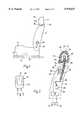
- FIG. 1shows a side view of an adjustable vehicle seat with a seat part, back rest and head support for a passenger car;
- FIG. 2shows a longitudinal section through a back rest and head restraint, with a block diagram of an automatic adjusting mechanism for the head restraint;
- FIG. 3shows a front view of the head restraint in FIGS. 1 and 2;
- FIG. 4shows a longitudinal section through a head restraint, with a block diagram of an automatic adjusting mechanism
- FIG. 5shows the same illustration as in FIG. 2, with a modified automatic adjusting mechanism.
- the passenger car seat illustrated in a side view in FIG. 1 and capable of being adjusted in order to adapt the seat positionhas a seat part 11 displaceable in the seat. longitudinal direction, a back rest 12 held on the seat part and a head restraint 13 held on the back rest 12.
- the seat part 11is guided so as to be longitudinally displaceable along longitudinal rails 14 fastened to the vehicle floor 10 and can be fixed non-displaceably in any set seat position by means of a locking device not illustrated here.
- the seat part 11can be displaced longitudinally either by hand or by motor operation.
- the seat partmay also be designed so as to be adjustable in height and inclination in relation to the vehicle floor 10 and has corresponding servomotors at its disposal.
- the back rest 12is arranged pivotably about a pivot axis fixed in the seat part 11 and running transversely to the longitudinal rails 14 and can be adjusted in its inclination in relation to the sitting surface of the seat part 11 by means of a handwheel 15. Instead of a handwheel 15, an electromotive inclination adjuster may also be provided.
- the head restraint 13has a carrying shackle 16 which is guided so as to be longitudinally displaceable in the back rest 12 and which emerges through an orifice on the top side of the back rest 12.
- a head cushion 17is fastened to the free end of the carrying shackle 16.
- a motor-operated head-restraint adjuster 18is arranged in the back rest 12 and, in the example of FIG. 2, is designed as an electric motor 19 with a toothed gear, the output pinion 20 of which engages into a rack 21 arranged on the carrying shackle 16.
- the rotating output pinion 20 of the toothed geardisplaces a carrying shackle 16 along a guide 22, so that the distance between the head cushion 17 and the top side of the back rest 12 increases or decreases depending on the output pinion 20.
- the head cushion 17has a foam cushion 23 which is enclosed by a cushion cover 24.
- the cushion cover 24is arranged partially in folds on the underside, so that it can enclose a larger volume after the folds have been pulled out.
- a neck restraint (172)is also designed on the head restraint 17.
- the neck restraintcomprises a somewhat softer material than the cushion cover 24 on the cushion front face 171 and serves to secure the cervical vertebra of the spinal column in the event of an accident, so that this part of the spinal column cannot be displaced to such a great extent in relation to the skull.
- a flexible medium reservoir 25Arranged inside the foam cushion 23 is a flexible medium reservoir 25 of variable volume, which is connected to a filling and discharge device 26 for a gaseous or liquid medium.
- the medium reservoir 25is designed, here, as an air hose 27 and the filling and discharge device 26 as a controllable compressed-air pump 29.
- the air hose 27is laid in a U-shaped manner around the free end of the carrying shackle 16 and is fixed to the shackle by means of its rear hose half 271.
- a compressed-air conduit 28leads through the hollow carrying shackle 16, opens out in the air hose 27, and is connected to the compressed-air pump 29 integrated in the back rest 12.
- the compressed-air pump 29, like the electric motor 19,is controlled by a control unit 30 which is integrated in the back rest 12 and which is connected on the input side to two sensors 31, 32.
- the sensor 31detects the longitudinal displacement of the seat part 11 and the sensor 32 detects the angle of inclination of the back rest 12 in relation to the sitting surface of the seat part 11.
- the spatial arrangement of the sensors 31, 32is illustrated by broken lines in FIG. 1.
- the compressed-air pump 29When the compressed-air pump 29 is switched on, it fills the air hose 27. Due to the stretching of the air hose 27, the front hose half 272 lifts off from the carrying shackle 16 and pushes the front face 171 of the head cushion 17, together with the neck restraint 172, forwards in the direction of the back of the head of the person sitting on the seat.
- a pressure limiter 33is provided in the air hose 27.
- a bleed valve controlled by the control unit 30may be integrated in the compressed-air pump 29.
- the control unit 30stores a characteristic diagram, the so-called seat adjustment diagram, in which there is a predetermined relationship between parameters of the seat adjustment, for example the longitudinal displacement of the seat part and the inclination of the back rest, and the horizontal and vertical setting of the head cushion 17.
- the settings of the head cushion 17are determined by (1) the displacement travel of the carrying shackle 16 in its guide 22; and (2) the filling quantity of the air hose 27.
- the longitudinal displacement of the seat partis detected by the sensor 31 and the adjustment of the back rest inclination by the sensor 32 and transmitted as electrical signals to the control unit 30.
- the control unit 30reads out from the seat adjustment diagram the corresponding regulating variables for the adjusting movement of the carrying shackle 16 and the filling quantity for the air hose 27.
- the electric motor 19 and the compressed-air pump 29are switched on for a corresponding period of time, in which the displacement of the carrying shackle 16 and the filling of the air hose 27 take place.
- the head cushion 17is thereby (1) adjusted in height, so that it is at the same height as the back of the seated person's head and his neck region and; (2) brought in the horizontal direction nearer to or further away from the back of the seated person's head and his neck. After the final setting, the head cushion 17 automatically assumes the position, which is the best possible in safety terms, in relation to the seated person's head, at a slight distance from the back of the head which is favourable from the point of view of an impact.
- FIG. 4illustrates another exemplary embodiment of a head restraint 17 with a filling and discharge device 26.
- the medium reservoir 25is designed, here, as an airbag or air buffer 34 which is arranged in the centre of the foam cushion 23.
- the foam cushion 23is firmly connected, on its rear side located behind the air buffer 34, to the carrying shackle 16 which is of hollow design and which functions as a compressed-air conduit 28.
- the air buffer 34is connected to the compressed-air conduit 28 via a connection piece 35. When the air buffer 34 is filled with compressed air, it expands and pushes the front face 171 of the head cushion 17 in the direction of the back of the seated person's head.
- a tension spring 36is tensioned, connecting the front part of the foam cushion 23 to the rear part of the foam cushion 23 or to the carrying shackle 16 below the air buffer 34.
- the cushion cover 24, once again arranged in folds on the underside of the head cushion 17,can span a substantially larger volume of the head cushion 17, so that the adjusting movement of the front part of the foam cushion 23 during the expansion of the air buffer 34 is not impeded.
- the amount of displacement movement of the front face 171 of the head cushion 17 during the expansion of the air bufferis detected by a displacement sensor 37 and transmitted as a feedback signal to the control unit 30.
- the displacement movement of the front face 171 of the head cushion 17may also be detected by means of other equivalent variables, for example by means of the pressure in the air buffer 34.
- a pressure sensoris provided instead of the displacement sensor 37.
- the filling and discharge device 26once again designed as a pneumatic system, comprises a compressed-air source 38 consisting of a compressed-air pump 39 and compressed-air reservoir 40 and of a switching valve 41 which is connected on the input side to the compressed-air source 38 and on the output side to the compressed-air conduit 38 leading to the air buffer 34.
- the switching valve 41is designed as a 3/3-way solenoid valve which makes it possible, in one switching position, to fill the air buffer 34 by means of the compressed-air source 38 and, in its other switching position, to bleed the air buffer 34. In the middle position, the air buffer 34 and compressed-air source 38 are shut off hermetically, so that the filling quantity in the air buffer 34 is kept constant for a relatively long period of time.
- a pressure-limiting valve 42which performs the function of the pressure limiter 33 in FIG. 2, that is to say ensures that the air pressure fed into the air buffer 34 does not exceed a predetermined value.
- the switching valve 41is controlled by the control unit 30, to which the electrical output signals from the sensors 31, 32 are supplied as input signals.
- the head restraint 13is set in dependence on the seat setting in the same way as described above. If the seat is occupied by a large person, in order to adapt his seat position he will carry out a longitudinal displacement of the seat part to the rear and an setting of the back rest 12 with greater inclination.
- the seat-setting change detected by the sensors 31, 32is supplied to the control unit 30 which in turn, by means of these parameters, determines from the seat adjustment diagram the necessary filling quantity for the air buffer 34 and the displacement travel for the carrying shackle 16 of the head restraint 13, so that the head restraint 13 is adapted as well as possible to the body size of the seated person.
- the control unit 30then activates the motor-operated head restraint adjuster 18 for the vertical displacement of the head cushion 17 and switches the switching valve 41 into one end position for a predetermined period of time, so that air flows out of the compressed-air reservoir 40 into the air buffer 34.
- the air buffer 34expands and pushes the front face 171 of the head cushion 17 nearer to the back of the seated person's head and the region of his cervical vertebra, the tension spring 36 being tensioned at the same time.
- the control unit 30switches off the switching valve 41 and the latter assumes its middle switching position, in which the air buffer 34 is closed off hermetically.
- the displacement of the front face 171 of the head cushion 17is detected by the displacement sensor 37 and transmitted as a feedback signal to the control unit 30 which, in response to this signal, may, if appropriate, carry out a correction of the filling quantity.
- the head restraint 13is thus set as well as possible for the large seat user.
- the seated person's headis intercepted in the correct region by the head cushion 17 and the air buffer 34 cushions the impact. If the air in the air buffer 34 is compressed excessively as a result of the impact of the head, the pressure-limiting valve 42 opens and allows air to escape into the environment. This prevents the air buffer 34 from forming a "reflection wall" at the end of its resilient range as a result of the high air compression and prevents accelerating the seated person's head forward again.
- the regulating variables, read out from the seat adjustment diagram, for the longitudinal displacement of the carrying shackle 16 and for the filling of the air buffer 34 with airlead (1) to a downward displacement movement of the carrying shackle 16, over the distance between the head cushion 17 and the top edge of the back rest 12; and (2) to switching valve 41 to its bleeding position, so that the air buffer 34 is connected to the environment. Under the spring force of the tensioned tension spring 36, the air buffer 34 is compressed, the air flowing out via the switching valve 41, until the predetermined filling quantity is reached. Thereafter, both the motor-operated head restraint adjuster 18 and the switching valve 41 are switched off, with the result that the latter assumes its shut-off position, illustrated in FIG. 4, and closes off the filling quantity in the air buffer 34 hermetically.
- FIG. 5illustrates another embodiment of a head restraint 17, in which a separate filling and discharge device for the medium reservoir 25 designed as an air hose 27 has been dispensed with and use is made, instead, of a pneumatic system 50, already present in the vehicle seat, for a pneumatically adjustable lower-back support 51 integrated in the back rest 12.
- the pneumatic system 50comprises a compressed-air source 52 and a compressed-air reservoir 53 for one or more air buffers 54, for example lower-back support and side cheeks.
- a valve 55which is responsible for filling the air buffer 54, is activated by a control unit 56.
- the air hose 27 of the head restraint 17is connected to the compressed-air source 52 and the compressed-air reservoir 53 via a valve 57 and is activated by the control unit 30 in order to predetermine the air quantity.
- the seat illustrated in FIG. 5otherwise corresponds to the seat according to FIG. 2 so that the same parts are provided with the same reference symbols.
- the present inventionis not restricted to the embodiments described above.
- further parameters for existing possibilities for adjusting the seat part and back restfor example seat-part inclination, height of the seat part above the vehicle floor and the like, may be stored in the seat adjustment diagram and also taken into account during the adjustment of the seat.
- a computing programmay also be provided, into which the sensor-detected parameters of the various seat settings are entered.
- a pluralitymay also be provided, or the air hose 27 and air buffer 34 may be subdivided into a plurality of cells.
Landscapes
- Engineering & Computer Science (AREA)
- Aviation & Aerospace Engineering (AREA)
- Transportation (AREA)
- Mechanical Engineering (AREA)
- Seats For Vehicles (AREA)
- Chair Legs, Seat Parts, And Backrests (AREA)
- Chairs For Special Purposes, Such As Reclining Chairs (AREA)
- Vehicle Waterproofing, Decoration, And Sanitation Devices (AREA)
Abstract
Description
Claims (22)
Applications Claiming Priority (2)
| Application Number | Priority Date | Filing Date | Title |
|---|---|---|---|
| DE19756700ADE19756700C1 (en) | 1997-12-19 | 1997-12-19 | Adjustable vehicle seat |
| DE19756700 | 1997-12-19 |
Publications (1)
| Publication Number | Publication Date |
|---|---|
| US5975637Atrue US5975637A (en) | 1999-11-02 |
Family
ID=7852632
Family Applications (1)
| Application Number | Title | Priority Date | Filing Date |
|---|---|---|---|
| US09/213,237Expired - LifetimeUS5975637A (en) | 1997-12-19 | 1998-12-17 | Adjustable vehicle seat |
Country Status (6)
| Country | Link |
|---|---|
| US (1) | US5975637A (en) |
| JP (1) | JP3108684B2 (en) |
| DE (1) | DE19756700C1 (en) |
| FR (1) | FR2772687B1 (en) |
| GB (1) | GB2332368B (en) |
| IT (1) | IT1302929B1 (en) |
Cited By (74)
| Publication number | Priority date | Publication date | Assignee | Title |
|---|---|---|---|---|
| US6460934B1 (en)* | 1999-08-20 | 2002-10-08 | Daimlerchrysler Ag | Electric adjusting device for a front seat of a motor vehicle |
| US6474733B1 (en) | 1999-04-23 | 2002-11-05 | Trw Occupant Restraint Systems Gmbh & Co. Kg | Inflatable headrest |
| US6568754B1 (en) | 2000-10-30 | 2003-05-27 | Ford Global Technologies, Llc | Expandable, redeployable automotive headrest |
| US6573673B1 (en)* | 1998-05-20 | 2003-06-03 | Brose Fahrzeugteile Gmbh & Co. Kg, Coburg | Adjustable vehicle seat with horizontal seat adjustment and/or seat height adjustment and/or seat depth adjustment and neck-rest that can be displaced by an electric motor and guided by a sensor system influenced by the size of the user |
| US6607242B2 (en)* | 2000-12-13 | 2003-08-19 | Lear Corporation | Head restraint assembly |
| US6637072B2 (en) | 2000-09-29 | 2003-10-28 | Formway Furniture Limited | Castored base for an office chair |
| EP1176049A3 (en)* | 2000-07-26 | 2004-01-28 | DaimlerChrysler AG | Headrest |
| US6726283B2 (en)* | 2002-05-15 | 2004-04-27 | Daimlerchrysler Corporation | Gear driven actuator for retractable headrest |
| US20040080198A1 (en)* | 2002-10-25 | 2004-04-29 | Richard Frank | Seat bolster system apparatus and method |
| US20040140691A1 (en)* | 2001-10-29 | 2004-07-22 | Toshiyuki Horimatsu | Shock absorbing material |
| US6802566B2 (en) | 2000-09-28 | 2004-10-12 | Formway Furniture Limited | Arm assembly for a chair |
| US6840582B2 (en) | 2002-05-14 | 2005-01-11 | Formway Furniture Limited | Height adjustable arm assembly |
| US20050023878A1 (en)* | 2003-07-30 | 2005-02-03 | Itw Automotive Products Gmbh & Co. Kg | Neck rest for the back rest of automobile seats, in particular rear seats |
| FR2861342A1 (en)* | 2003-10-28 | 2005-04-29 | Marc Lefevere | Active head-rest for use with automobile seat, has unit that is placed at interior of back-rest and rotates around axis when body of user rebounds to cause rotation of frame work within head-rest cushion |
| US20050116523A1 (en)* | 2003-11-21 | 2005-06-02 | Takami Terada | Headrest device |
| RU2261808C1 (en)* | 2004-06-28 | 2005-10-10 | Смирнов Борис Леонидович | Automatic headrest |
| US20050225145A1 (en)* | 2002-01-29 | 2005-10-13 | Roland Furtado | Vehicle seat having a head restraint independent from its backrest |
| WO2005100084A1 (en)* | 2004-04-14 | 2005-10-27 | Daimlerchrysler Ag | Safety device for a motor vehicle |
| US20050280304A1 (en)* | 2004-06-16 | 2005-12-22 | Fumitoshi Akaike | Head rests |
| US20060001308A1 (en)* | 2004-06-30 | 2006-01-05 | Lear Corporation | Vehicle seat having a moveable head restraint |
| US20060006708A1 (en)* | 2004-03-09 | 2006-01-12 | Burckhard Becker | Headrest of an automotive vehicle set with a pressurized gas drive system |
| US20060071514A1 (en)* | 2004-10-01 | 2006-04-06 | Lear Corporation | Vehicle seat and head restraint assembly |
| US20060103216A1 (en)* | 2004-11-18 | 2006-05-18 | Craig Hoekstra | Spring-loaded headrest |
| US20060170271A1 (en)* | 2004-06-16 | 2006-08-03 | Coccoli Oreste M | Pneumatically positioned headrest |
| US20060175881A1 (en)* | 2004-12-28 | 2006-08-10 | Fumitoshi Akaike | Head rests |
| US20070096515A1 (en)* | 2005-11-02 | 2007-05-03 | Lear Corporation | Folding head restraint mechanism |
| US7232187B1 (en) | 2006-03-30 | 2007-06-19 | Ford Global Technologies, Llc | Head restraint for automotive vehicle |
| US20070145796A1 (en)* | 2005-12-26 | 2007-06-28 | Aisin Seiki Kabushiki Kaisha | Headrest apparatus |
| US20070216211A1 (en)* | 2006-03-20 | 2007-09-20 | Aisin Seiki Kabushiki Kaisha | Headrest height adjusting apparatus |
| US20080111407A1 (en)* | 2005-03-08 | 2008-05-15 | Piotr Szablewski | Backrest for a vehicle seat |
| US20080217971A1 (en)* | 2005-10-25 | 2008-09-11 | Paluch Zbigniew A | Active Head Restraint |
| US20080315653A1 (en)* | 2007-06-25 | 2008-12-25 | Lear Corporation | Automatic headrest activation gear |
| US20090045662A1 (en)* | 2007-08-14 | 2009-02-19 | Schukra Of North America, Ltd. | Head Rest for Seat |
| US20090102254A1 (en)* | 2007-10-17 | 2009-04-23 | Lear Corporation | Active head restraint system with actuating system for a vehicle seat |
| US20090315372A1 (en)* | 2008-06-23 | 2009-12-24 | Lear Corporation | Vehicle seat including an energy absorption device |
| US20100117410A1 (en)* | 2007-04-20 | 2010-05-13 | Toyota Boshoku Kabushiki Kaisha | Vehicle seat |
| CN101992715A (en)* | 2009-08-18 | 2011-03-30 | 格瑞玛股份公司 | Headrest |
| DE202011003985U1 (en) | 2011-03-15 | 2011-06-01 | Smirnova, Olga Borisovna | Automatic headrest (SBL) |
| CN102673449A (en)* | 2011-03-16 | 2012-09-19 | 李尔公司 | Automatic head restraint adjustment system for vehicle seat |
| US20140054944A1 (en)* | 2012-08-23 | 2014-02-27 | Lear Corporation | Vehicle seat head restraint actuation |
| US9308998B1 (en)* | 2015-01-05 | 2016-04-12 | Ami Industries, Inc. | Removable aircraft headrest |
| US9340131B1 (en)* | 2014-11-06 | 2016-05-17 | Ford Global Technologies, Llc | Head restraint with a multi-cell bladder assembly |
| US9649962B2 (en) | 2013-01-24 | 2017-05-16 | Ford Global Technologies, Llc | Independent cushion extension and thigh support |
| US9707870B2 (en) | 2013-01-24 | 2017-07-18 | Ford Global Technologies, Llc | Flexible seatback system |
| US9707873B2 (en) | 2013-01-24 | 2017-07-18 | Ford Global Technologies, Llc | Flexible seatback system |
| US9713974B2 (en)* | 2015-10-23 | 2017-07-25 | Fca Us Llc | Vehicle seat with head and neck support |
| US9802512B1 (en) | 2016-04-12 | 2017-10-31 | Ford Global Technologies, Llc | Torsion spring bushing |
| US9834166B1 (en) | 2016-06-07 | 2017-12-05 | Ford Global Technologies, Llc | Side airbag energy management system |
| US9845029B1 (en) | 2016-06-06 | 2017-12-19 | Ford Global Technologies, Llc | Passive conformal seat with hybrid air/liquid cells |
| US9849817B2 (en) | 2016-03-16 | 2017-12-26 | Ford Global Technologies, Llc | Composite seat structure |
| US9849856B1 (en) | 2016-06-07 | 2017-12-26 | Ford Global Technologies, Llc | Side airbag energy management system |
| US9889773B2 (en) | 2016-04-04 | 2018-02-13 | Ford Global Technologies, Llc | Anthropomorphic upper seatback |
| US9914378B1 (en) | 2016-12-16 | 2018-03-13 | Ford Global Technologies, Llc | Decorative and functional upper seatback closeout assembly |
| US9994135B2 (en) | 2016-03-30 | 2018-06-12 | Ford Global Technologies, Llc | Independent cushion thigh support |
| US10023075B2 (en) | 2016-06-17 | 2018-07-17 | Toyota Motor Engineering & Manufacturing North America, Inc | Automatically adjusting vehicle seat back supports of vehicle seat assemblies |
| US10046682B2 (en) | 2015-08-03 | 2018-08-14 | Ford Global Technologies, Llc | Back cushion module for a vehicle seating assembly |
| US10046683B2 (en) | 2014-01-23 | 2018-08-14 | Ford Global Technologies, Llc | Suspension seat back and cushion system having an inner suspension panel |
| US10065546B2 (en) | 2014-04-02 | 2018-09-04 | Ford Global Technologies, Llc | Vehicle seating assembly with manual independent thigh supports |
| US20180339625A1 (en)* | 2017-05-23 | 2018-11-29 | Toyota Boshoku Kabushiki Kaisha | Vehicle seat |
| US10160352B2 (en)* | 2016-06-30 | 2018-12-25 | GM Global Technology Operations LLC | Motor vehicle seat and motor vehicle with such a motor vehicle seat |
| US10166895B2 (en) | 2016-06-09 | 2019-01-01 | Ford Global Technologies, Llc | Seatback comfort carrier |
| US10220737B2 (en) | 2016-04-01 | 2019-03-05 | Ford Global Technologies, Llc | Kinematic back panel |
| US10239431B2 (en) | 2016-09-02 | 2019-03-26 | Ford Global Technologies, Llc | Cross-tube attachment hook features for modular assembly and support |
| US10279714B2 (en) | 2016-08-26 | 2019-05-07 | Ford Global Technologies, Llc | Seating assembly with climate control features |
| US10286824B2 (en) | 2016-08-24 | 2019-05-14 | Ford Global Technologies, Llc | Spreader plate load distribution |
| US10286818B2 (en) | 2016-03-16 | 2019-05-14 | Ford Global Technologies, Llc | Dual suspension seating assembly |
| US10299601B2 (en)* | 2015-09-17 | 2019-05-28 | Sv Tool Corporation | Auto-adjusting headrest for an ergonomic chair |
| US20190176670A1 (en)* | 2017-12-13 | 2019-06-13 | Lear Corporation | Vehicle head restraint with movement mechanism |
| US10369905B2 (en) | 2014-10-03 | 2019-08-06 | Ford Global Technologies, Llc | Tuned flexible support member and flexible suspension features for comfort carriers |
| US10377279B2 (en) | 2016-06-09 | 2019-08-13 | Ford Global Technologies, Llc | Integrated decking arm support feature |
| US10384566B2 (en)* | 2017-08-25 | 2019-08-20 | Ford Global Technologies, Llc | Vehicle seat assembly |
| US10391910B2 (en) | 2016-09-02 | 2019-08-27 | Ford Global Technologies, Llc | Modular assembly cross-tube attachment tab designs and functions |
| US10596936B2 (en) | 2017-05-04 | 2020-03-24 | Ford Global Technologies, Llc | Self-retaining elastic strap for vent blower attachment to a back carrier |
| US10946772B2 (en)* | 2016-07-19 | 2021-03-16 | Hyundai Dymos Incorporated | Apparatus and method for controlling headrest of vehicle seat |
Families Citing this family (16)
| Publication number | Priority date | Publication date | Assignee | Title |
|---|---|---|---|---|
| CA2285813A1 (en)* | 1998-12-07 | 2000-06-07 | Basf Corporation | Polyurethane foam seating components |
| DE19946404C2 (en)* | 1999-09-28 | 2003-10-30 | Siemens Restraint Systems Gmbh | System for suddenly reducing the distance between the headrest and the head of a vehicle occupant |
| DE19947309A1 (en)* | 1999-10-01 | 2001-04-05 | Volkswagen Ag | Headrest with a swiveling headrest front part |
| DE10233477B4 (en)* | 2002-07-24 | 2007-09-20 | Faurecia Autositze Gmbh | Vehicle seat, in particular motor vehicle seat |
| DE102004030319A1 (en)* | 2004-06-23 | 2006-01-12 | Faurecia Autositze Gmbh & Co. Kg | Headrest assembly for a vehicle seat |
| JP4661179B2 (en)* | 2004-11-18 | 2011-03-30 | トヨタ紡織株式会社 | Vehicle seat headrest device |
| JP4854274B2 (en)* | 2005-11-10 | 2012-01-18 | 日本テクニカ株式会社 | Active headrest |
| GB2444833B (en)* | 2006-12-12 | 2011-12-07 | Wonderland Nursery Goods | Reversible child car seat with separable base member |
| JP4404915B2 (en)* | 2007-04-19 | 2010-01-27 | 三菱電機株式会社 | Vehicle occupant protection device |
| KR101374570B1 (en)* | 2011-05-24 | 2014-03-25 | 박영순 | A office chair with massage function |
| KR101374566B1 (en)* | 2011-05-24 | 2014-03-17 | 박영순 | A office chair with massage function |
| DE102011107677B4 (en)* | 2011-07-13 | 2013-12-05 | Faurecia Autositze Gmbh | vehicle seat |
| KR101363788B1 (en)* | 2012-08-06 | 2014-02-14 | 현대다이모스(주) | Passenger protecting apparatus of vehiclef |
| JP6449827B2 (en) | 2016-09-23 | 2019-01-09 | アイシン精機株式会社 | Intake / exhaust valve device and vehicle seat device |
| JP7404990B2 (en)* | 2020-04-17 | 2023-12-26 | トヨタ紡織株式会社 | vehicle seat |
| DE102024200563A1 (en)* | 2024-01-22 | 2025-07-24 | Volkswagen Aktiengesellschaft | Vehicle seat with a pneumatically operated headrest tilt adjustment device |
Citations (13)
| Publication number | Priority date | Publication date | Assignee | Title |
|---|---|---|---|---|
| US3680912A (en)* | 1970-09-14 | 1972-08-01 | Hirotsugu Matsura | Head-rest of the shock absorbing system |
| DE2152202A1 (en)* | 1971-10-20 | 1973-04-26 | Opel Adam Ag | HEADREST, ESPECIALLY FOR MOTOR VEHICLES |
| US4222608A (en)* | 1977-12-30 | 1980-09-16 | Nissan Motor Company, Limited | Control system for adjustable head restraint on automotive seat |
| DE3141515A1 (en)* | 1981-10-20 | 1983-04-28 | C. Rob. Hammerstein Gmbh, 5650 Solingen | Vehicle seat with a vertically adjustable headrest |
| US4655505A (en)* | 1984-12-13 | 1987-04-07 | Nhk Spring Co., Ltd. | Pneumatically controlled seat for vehicle |
| US4720146A (en)* | 1986-08-28 | 1988-01-19 | General Motors Corporation | Vehicle seat headrest apparatus and method |
| DE3718126A1 (en)* | 1987-05-29 | 1988-12-15 | Audi Ag | Combined longitudinal and vertical seat adjustment for vehicle seats |
| US4923250A (en)* | 1987-02-28 | 1990-05-08 | Aisin Seiki Kabushiki Kaisha | Headrest apparatus |
| US5330255A (en)* | 1992-11-12 | 1994-07-19 | Davidson Textron Inc. | Seat integrated inflatable neck support |
| US5439271A (en)* | 1993-11-08 | 1995-08-08 | Hoover Universal, Inc. | Vehicle seat with extruded frame members |
| US5458396A (en)* | 1989-02-06 | 1995-10-17 | Audi Ag | Roll bar for convertible motor vehicles |
| DE4409046C2 (en)* | 1994-03-12 | 1996-12-19 | Brose Fahrzeugteile | Device for adjusting the position and / or angular position of vehicle equipment |
| US5782529A (en)* | 1997-02-20 | 1998-07-21 | Alliedsignal Inc. | Inflatable seat back |
Family Cites Families (4)
| Publication number | Priority date | Publication date | Assignee | Title |
|---|---|---|---|---|
| FR2741574B1 (en)* | 1995-11-24 | 1998-01-09 | Renault | HEADREST DEVICE WITH INTEGRATED CERVICAL SUPPORT |
| DE19622662C2 (en)* | 1996-06-05 | 2003-05-22 | Kendrion Rsl Gmbh & Co Kg | Seat with a headrest that contains an integrated gas cushion of an airbag device |
| DE19648268A1 (en)* | 1996-11-21 | 1998-05-28 | Siemens Ag | Vehicle seat with a control device |
| US6055473A (en)* | 1997-02-19 | 2000-04-25 | General Motors Corporation | Adaptive seating system |
- 1997
- 1997-12-19DEDE19756700Apatent/DE19756700C1/ennot_activeExpired - Fee Related
- 1998
- 1998-12-04GBGB9826782Apatent/GB2332368B/ennot_activeExpired - Fee Related
- 1998-12-17USUS09/213,237patent/US5975637A/ennot_activeExpired - Lifetime
- 1998-12-18FRFR9816010Apatent/FR2772687B1/ennot_activeExpired - Fee Related
- 1998-12-18ITIT1998RM000779Apatent/IT1302929B1/enactiveIP Right Grant
- 1998-12-18JPJP10375825Apatent/JP3108684B2/ennot_activeExpired - Fee Related
Patent Citations (13)
| Publication number | Priority date | Publication date | Assignee | Title |
|---|---|---|---|---|
| US3680912A (en)* | 1970-09-14 | 1972-08-01 | Hirotsugu Matsura | Head-rest of the shock absorbing system |
| DE2152202A1 (en)* | 1971-10-20 | 1973-04-26 | Opel Adam Ag | HEADREST, ESPECIALLY FOR MOTOR VEHICLES |
| US4222608A (en)* | 1977-12-30 | 1980-09-16 | Nissan Motor Company, Limited | Control system for adjustable head restraint on automotive seat |
| DE3141515A1 (en)* | 1981-10-20 | 1983-04-28 | C. Rob. Hammerstein Gmbh, 5650 Solingen | Vehicle seat with a vertically adjustable headrest |
| US4655505A (en)* | 1984-12-13 | 1987-04-07 | Nhk Spring Co., Ltd. | Pneumatically controlled seat for vehicle |
| US4720146A (en)* | 1986-08-28 | 1988-01-19 | General Motors Corporation | Vehicle seat headrest apparatus and method |
| US4923250A (en)* | 1987-02-28 | 1990-05-08 | Aisin Seiki Kabushiki Kaisha | Headrest apparatus |
| DE3718126A1 (en)* | 1987-05-29 | 1988-12-15 | Audi Ag | Combined longitudinal and vertical seat adjustment for vehicle seats |
| US5458396A (en)* | 1989-02-06 | 1995-10-17 | Audi Ag | Roll bar for convertible motor vehicles |
| US5330255A (en)* | 1992-11-12 | 1994-07-19 | Davidson Textron Inc. | Seat integrated inflatable neck support |
| US5439271A (en)* | 1993-11-08 | 1995-08-08 | Hoover Universal, Inc. | Vehicle seat with extruded frame members |
| DE4409046C2 (en)* | 1994-03-12 | 1996-12-19 | Brose Fahrzeugteile | Device for adjusting the position and / or angular position of vehicle equipment |
| US5782529A (en)* | 1997-02-20 | 1998-07-21 | Alliedsignal Inc. | Inflatable seat back |
Cited By (111)
| Publication number | Priority date | Publication date | Assignee | Title |
|---|---|---|---|---|
| US6573673B1 (en)* | 1998-05-20 | 2003-06-03 | Brose Fahrzeugteile Gmbh & Co. Kg, Coburg | Adjustable vehicle seat with horizontal seat adjustment and/or seat height adjustment and/or seat depth adjustment and neck-rest that can be displaced by an electric motor and guided by a sensor system influenced by the size of the user |
| US6474733B1 (en) | 1999-04-23 | 2002-11-05 | Trw Occupant Restraint Systems Gmbh & Co. Kg | Inflatable headrest |
| US6460934B1 (en)* | 1999-08-20 | 2002-10-08 | Daimlerchrysler Ag | Electric adjusting device for a front seat of a motor vehicle |
| EP1176049A3 (en)* | 2000-07-26 | 2004-01-28 | DaimlerChrysler AG | Headrest |
| US6824211B2 (en) | 2000-07-26 | 2004-11-30 | Daimlerchrysler Ag | Head restraint and method of making and using same |
| US6817667B2 (en) | 2000-09-28 | 2004-11-16 | Formway Furniture Limited | Reclinable chair |
| US6908159B2 (en) | 2000-09-28 | 2005-06-21 | Formway Furniture Limited | Seat for a reclining office chair |
| US6910741B2 (en) | 2000-09-28 | 2005-06-28 | Formway Furniture Limited | Lumbar support |
| US7798573B2 (en) | 2000-09-28 | 2010-09-21 | Formway Furniture Limited | Reclinable chair |
| US7441839B2 (en) | 2000-09-28 | 2008-10-28 | Formway Furniture Limited | Reclinable chair |
| US6874852B2 (en) | 2000-09-28 | 2005-04-05 | Formway Furniture Limited | Lumbar support |
| US6802566B2 (en) | 2000-09-28 | 2004-10-12 | Formway Furniture Limited | Arm assembly for a chair |
| US6637072B2 (en) | 2000-09-29 | 2003-10-28 | Formway Furniture Limited | Castored base for an office chair |
| US6568754B1 (en) | 2000-10-30 | 2003-05-27 | Ford Global Technologies, Llc | Expandable, redeployable automotive headrest |
| US6607242B2 (en)* | 2000-12-13 | 2003-08-19 | Lear Corporation | Head restraint assembly |
| US20040140691A1 (en)* | 2001-10-29 | 2004-07-22 | Toshiyuki Horimatsu | Shock absorbing material |
| US20050225145A1 (en)* | 2002-01-29 | 2005-10-13 | Roland Furtado | Vehicle seat having a head restraint independent from its backrest |
| US7044554B2 (en)* | 2002-01-29 | 2006-05-16 | Intier Automotive Inc. | Vehicle seat having a head restraint independent from its backrest |
| US6840582B2 (en) | 2002-05-14 | 2005-01-11 | Formway Furniture Limited | Height adjustable arm assembly |
| US6726283B2 (en)* | 2002-05-15 | 2004-04-27 | Daimlerchrysler Corporation | Gear driven actuator for retractable headrest |
| EP1558114A4 (en)* | 2002-10-25 | 2010-04-28 | L & P Property Management Co | Seat bolster system apparatus and method |
| CN100439147C (en)* | 2002-10-25 | 2008-12-03 | L&P财产管理公司 | Seat bolster system apparatus and method |
| WO2004037045A1 (en) | 2002-10-25 | 2004-05-06 | L & P Property Management Company | Seat bolster system apparatus and method |
| US7125077B2 (en)* | 2002-10-25 | 2006-10-24 | L&P Property Management Company | Seat bolster adjustment apparatus and method |
| US20040080198A1 (en)* | 2002-10-25 | 2004-04-29 | Richard Frank | Seat bolster system apparatus and method |
| US6942293B2 (en)* | 2003-07-30 | 2005-09-13 | Itw Automotive Products Gmbh & Co. Kg | Neck rest for the back rest of automobile seats, in particular rear seats |
| US20050023878A1 (en)* | 2003-07-30 | 2005-02-03 | Itw Automotive Products Gmbh & Co. Kg | Neck rest for the back rest of automobile seats, in particular rear seats |
| FR2861342A1 (en)* | 2003-10-28 | 2005-04-29 | Marc Lefevere | Active head-rest for use with automobile seat, has unit that is placed at interior of back-rest and rotates around axis when body of user rebounds to cause rotation of frame work within head-rest cushion |
| US7066545B2 (en)* | 2003-11-21 | 2006-06-27 | Aisin Seiki Kabushiki Kaisha | Headrest device |
| US20050116523A1 (en)* | 2003-11-21 | 2005-06-02 | Takami Terada | Headrest device |
| US20060006708A1 (en)* | 2004-03-09 | 2006-01-12 | Burckhard Becker | Headrest of an automotive vehicle set with a pressurized gas drive system |
| US7438357B2 (en)* | 2004-03-09 | 2008-10-21 | C. Rob. Hammerstein Gmbh & Co. Kg | Headrest of an automotive vehicle seat with a pressurized gas drive system |
| WO2005100084A1 (en)* | 2004-04-14 | 2005-10-27 | Daimlerchrysler Ag | Safety device for a motor vehicle |
| US20070208474A1 (en)* | 2004-04-14 | 2007-09-06 | Frank Bertele | Safety Device and Method for a Motor Vehicle |
| US20060170271A1 (en)* | 2004-06-16 | 2006-08-03 | Coccoli Oreste M | Pneumatically positioned headrest |
| US7073856B2 (en)* | 2004-06-16 | 2006-07-11 | Toyota Boshoku Kabushiki Kaisha | Head rests |
| US20050280304A1 (en)* | 2004-06-16 | 2005-12-22 | Fumitoshi Akaike | Head rests |
| RU2261808C1 (en)* | 2004-06-28 | 2005-10-10 | Смирнов Борис Леонидович | Automatic headrest |
| US20060001308A1 (en)* | 2004-06-30 | 2006-01-05 | Lear Corporation | Vehicle seat having a moveable head restraint |
| US7104602B2 (en) | 2004-06-30 | 2006-09-12 | Lear Corporation | Vehicle seat having a moveable head restraint |
| US7159934B2 (en) | 2004-10-01 | 2007-01-09 | Lear Corporation | Vehicle seat and head restraint assembly |
| US20060071514A1 (en)* | 2004-10-01 | 2006-04-06 | Lear Corporation | Vehicle seat and head restraint assembly |
| US20060103216A1 (en)* | 2004-11-18 | 2006-05-18 | Craig Hoekstra | Spring-loaded headrest |
| US7140687B2 (en)* | 2004-11-18 | 2006-11-28 | Fisher Dynamics Corporation | Spring-loaded headrest |
| US20060175881A1 (en)* | 2004-12-28 | 2006-08-10 | Fumitoshi Akaike | Head rests |
| US7484797B2 (en)* | 2004-12-28 | 2009-02-03 | Toyota Boshoku Kabushiki Kaisha | Head rests |
| US7794012B2 (en)* | 2005-03-08 | 2010-09-14 | Brose Fahrzeugteile Gmbh & Co. Kommanditgesellschaft, Hallstadt | Backrest for a vehicle seat |
| US20080111407A1 (en)* | 2005-03-08 | 2008-05-15 | Piotr Szablewski | Backrest for a vehicle seat |
| US20080217971A1 (en)* | 2005-10-25 | 2008-09-11 | Paluch Zbigniew A | Active Head Restraint |
| US7322646B2 (en) | 2005-11-02 | 2008-01-29 | Lear Corporation | Folding head restraint mechanism |
| US20070096515A1 (en)* | 2005-11-02 | 2007-05-03 | Lear Corporation | Folding head restraint mechanism |
| US7350860B2 (en)* | 2005-12-26 | 2008-04-01 | Aisin Seiki Kabushiki Kaisha | Headrest apparatus |
| US20070145796A1 (en)* | 2005-12-26 | 2007-06-28 | Aisin Seiki Kabushiki Kaisha | Headrest apparatus |
| US20070216211A1 (en)* | 2006-03-20 | 2007-09-20 | Aisin Seiki Kabushiki Kaisha | Headrest height adjusting apparatus |
| US7445283B2 (en)* | 2006-03-20 | 2008-11-04 | Aisin Seiki Kabushiki Kaisha | Headrest height adjusting apparatus |
| US7232187B1 (en) | 2006-03-30 | 2007-06-19 | Ford Global Technologies, Llc | Head restraint for automotive vehicle |
| US8141945B2 (en)* | 2007-04-20 | 2012-03-27 | Toyota Boshoku Kabushiki Kaisha | Vehicle seat |
| US20100117410A1 (en)* | 2007-04-20 | 2010-05-13 | Toyota Boshoku Kabushiki Kaisha | Vehicle seat |
| US20080315653A1 (en)* | 2007-06-25 | 2008-12-25 | Lear Corporation | Automatic headrest activation gear |
| US7878596B2 (en)* | 2007-06-25 | 2011-02-01 | Lear Corporation | Automatic headrest activation gear |
| US20090045662A1 (en)* | 2007-08-14 | 2009-02-19 | Schukra Of North America, Ltd. | Head Rest for Seat |
| US7850235B2 (en)* | 2007-10-17 | 2010-12-14 | Lear Corporation | Active head restraint system with actuating system for a vehicle seat |
| US20090102254A1 (en)* | 2007-10-17 | 2009-04-23 | Lear Corporation | Active head restraint system with actuating system for a vehicle seat |
| US20090315372A1 (en)* | 2008-06-23 | 2009-12-24 | Lear Corporation | Vehicle seat including an energy absorption device |
| CN101992715A (en)* | 2009-08-18 | 2011-03-30 | 格瑞玛股份公司 | Headrest |
| US20110198899A1 (en)* | 2009-08-18 | 2011-08-18 | Juergen Hertl | Motor-vehicle headrest |
| US8469445B2 (en)* | 2009-08-18 | 2013-06-25 | Grammer Ag | Motor vehicle headrest |
| DE202011003985U1 (en) | 2011-03-15 | 2011-06-01 | Smirnova, Olga Borisovna | Automatic headrest (SBL) |
| CN102673449A (en)* | 2011-03-16 | 2012-09-19 | 李尔公司 | Automatic head restraint adjustment system for vehicle seat |
| US20120235459A1 (en)* | 2011-03-16 | 2012-09-20 | Lear Corporation | Automatic Head Restraint Adjustment System for a Vehicle Seat |
| US9457699B2 (en)* | 2011-03-16 | 2016-10-04 | Lear Corporation | Automatic head restraint adjustment system for a vehicle seat |
| US9145078B2 (en)* | 2012-08-23 | 2015-09-29 | Lear Corporation | Vehicle seat head restraint actuation |
| US20140054944A1 (en)* | 2012-08-23 | 2014-02-27 | Lear Corporation | Vehicle seat head restraint actuation |
| US9873360B2 (en) | 2013-01-24 | 2018-01-23 | Ford Global Technologies, Llc | Flexible seatback system |
| US9649962B2 (en) | 2013-01-24 | 2017-05-16 | Ford Global Technologies, Llc | Independent cushion extension and thigh support |
| US9707870B2 (en) | 2013-01-24 | 2017-07-18 | Ford Global Technologies, Llc | Flexible seatback system |
| US9707873B2 (en) | 2013-01-24 | 2017-07-18 | Ford Global Technologies, Llc | Flexible seatback system |
| US9873362B2 (en) | 2013-01-24 | 2018-01-23 | Ford Global Technologies, Llc | Flexible seatback system |
| US10046683B2 (en) | 2014-01-23 | 2018-08-14 | Ford Global Technologies, Llc | Suspension seat back and cushion system having an inner suspension panel |
| US10065546B2 (en) | 2014-04-02 | 2018-09-04 | Ford Global Technologies, Llc | Vehicle seating assembly with manual independent thigh supports |
| US10369905B2 (en) | 2014-10-03 | 2019-08-06 | Ford Global Technologies, Llc | Tuned flexible support member and flexible suspension features for comfort carriers |
| US9340131B1 (en)* | 2014-11-06 | 2016-05-17 | Ford Global Technologies, Llc | Head restraint with a multi-cell bladder assembly |
| US9308998B1 (en)* | 2015-01-05 | 2016-04-12 | Ami Industries, Inc. | Removable aircraft headrest |
| US10046682B2 (en) | 2015-08-03 | 2018-08-14 | Ford Global Technologies, Llc | Back cushion module for a vehicle seating assembly |
| US10299601B2 (en)* | 2015-09-17 | 2019-05-28 | Sv Tool Corporation | Auto-adjusting headrest for an ergonomic chair |
| US9713974B2 (en)* | 2015-10-23 | 2017-07-25 | Fca Us Llc | Vehicle seat with head and neck support |
| US10286818B2 (en) | 2016-03-16 | 2019-05-14 | Ford Global Technologies, Llc | Dual suspension seating assembly |
| US9849817B2 (en) | 2016-03-16 | 2017-12-26 | Ford Global Technologies, Llc | Composite seat structure |
| US9994135B2 (en) | 2016-03-30 | 2018-06-12 | Ford Global Technologies, Llc | Independent cushion thigh support |
| US10220737B2 (en) | 2016-04-01 | 2019-03-05 | Ford Global Technologies, Llc | Kinematic back panel |
| US9889773B2 (en) | 2016-04-04 | 2018-02-13 | Ford Global Technologies, Llc | Anthropomorphic upper seatback |
| US9802512B1 (en) | 2016-04-12 | 2017-10-31 | Ford Global Technologies, Llc | Torsion spring bushing |
| US9845029B1 (en) | 2016-06-06 | 2017-12-19 | Ford Global Technologies, Llc | Passive conformal seat with hybrid air/liquid cells |
| US9849856B1 (en) | 2016-06-07 | 2017-12-26 | Ford Global Technologies, Llc | Side airbag energy management system |
| US9834166B1 (en) | 2016-06-07 | 2017-12-05 | Ford Global Technologies, Llc | Side airbag energy management system |
| US10166895B2 (en) | 2016-06-09 | 2019-01-01 | Ford Global Technologies, Llc | Seatback comfort carrier |
| US10377279B2 (en) | 2016-06-09 | 2019-08-13 | Ford Global Technologies, Llc | Integrated decking arm support feature |
| US10023075B2 (en) | 2016-06-17 | 2018-07-17 | Toyota Motor Engineering & Manufacturing North America, Inc | Automatically adjusting vehicle seat back supports of vehicle seat assemblies |
| US10160352B2 (en)* | 2016-06-30 | 2018-12-25 | GM Global Technology Operations LLC | Motor vehicle seat and motor vehicle with such a motor vehicle seat |
| US10946772B2 (en)* | 2016-07-19 | 2021-03-16 | Hyundai Dymos Incorporated | Apparatus and method for controlling headrest of vehicle seat |
| US10286824B2 (en) | 2016-08-24 | 2019-05-14 | Ford Global Technologies, Llc | Spreader plate load distribution |
| US10279714B2 (en) | 2016-08-26 | 2019-05-07 | Ford Global Technologies, Llc | Seating assembly with climate control features |
| US10239431B2 (en) | 2016-09-02 | 2019-03-26 | Ford Global Technologies, Llc | Cross-tube attachment hook features for modular assembly and support |
| US10391910B2 (en) | 2016-09-02 | 2019-08-27 | Ford Global Technologies, Llc | Modular assembly cross-tube attachment tab designs and functions |
| US9914378B1 (en) | 2016-12-16 | 2018-03-13 | Ford Global Technologies, Llc | Decorative and functional upper seatback closeout assembly |
| US10596936B2 (en) | 2017-05-04 | 2020-03-24 | Ford Global Technologies, Llc | Self-retaining elastic strap for vent blower attachment to a back carrier |
| US20180339625A1 (en)* | 2017-05-23 | 2018-11-29 | Toyota Boshoku Kabushiki Kaisha | Vehicle seat |
| US10882430B2 (en)* | 2017-05-23 | 2021-01-05 | Toyota Boshoku Kabushiki Kaisha | Vehicle seat |
| US10384566B2 (en)* | 2017-08-25 | 2019-08-20 | Ford Global Technologies, Llc | Vehicle seat assembly |
| US10562426B2 (en)* | 2017-12-13 | 2020-02-18 | Lear Corporation | Vehicle head restraint with movement mechanism |
| US20190176670A1 (en)* | 2017-12-13 | 2019-06-13 | Lear Corporation | Vehicle head restraint with movement mechanism |
Also Published As
| Publication number | Publication date |
|---|---|
| GB2332368B (en) | 1999-12-22 |
| IT1302929B1 (en) | 2000-10-10 |
| FR2772687A1 (en) | 1999-06-25 |
| ITRM980779A1 (en) | 2000-06-18 |
| JPH11278130A (en) | 1999-10-12 |
| JP3108684B2 (en) | 2000-11-13 |
| DE19756700C1 (en) | 1998-12-17 |
| FR2772687B1 (en) | 2001-02-02 |
| GB2332368A (en) | 1999-06-23 |
| GB9826782D0 (en) | 1999-01-27 |
Similar Documents
| Publication | Publication Date | Title |
|---|---|---|
| US5975637A (en) | Adjustable vehicle seat | |
| US5842738A (en) | Headrest for a vehicle seat | |
| US6042145A (en) | Arrangement for adjusting the sitting position of a vehicle occupant | |
| US7478873B2 (en) | Safety device | |
| US6030036A (en) | Vehicle seat with gas bag located in the back rest | |
| US6398299B1 (en) | Motor vehicle seat with a back rest | |
| US6820930B2 (en) | Fluid-actuated support for vehicular seats | |
| US6390549B1 (en) | Backrest for a vehicle seat | |
| US7992933B2 (en) | Integrated vehicle seat with active head restraint system | |
| US20040061363A1 (en) | Vehicle seat having a lumbar support system | |
| US20150375647A1 (en) | Vehicle seat, in particular for a motor vehicle | |
| CA2289989A1 (en) | Energy absorbing support for vehicular passengers | |
| EP0677423A1 (en) | Neck support for a vehicle seat | |
| DE19938698A1 (en) | Vehicle seat | |
| US20050006941A1 (en) | Headrest for vehicles | |
| WO2001056830A1 (en) | Seat back with variable rigidity for vehicle seat | |
| US3468556A (en) | Automobile safety devices | |
| KR100506025B1 (en) | Seat having a head-rest of length variable | |
| EP1373013B1 (en) | Non-stop-active car headrest | |
| JPH079696Y2 (en) | Car seat structure | |
| KR100208617B1 (en) | Car seat shifter | |
| KR200154403Y1 (en) | Seat retractor for long time | |
| KR100802718B1 (en) | Air cushion device for car seat | |
| KR19980018814U (en) | Air back cushion adjustment device | |
| KR19990050312A (en) | Car Seat Frames |
Legal Events
| Date | Code | Title | Description |
|---|---|---|---|
| AS | Assignment | Owner name:DAIMLER-BENZ AKTIENGESELLSCHAFT, GERMANY Free format text:ASSIGNMENT OF ASSIGNORS INTEREST;ASSIGNORS:GEUSS, HARTWICH;REICHELT, WERNER;SCHMIDT-SPALDING, HELGE;REEL/FRAME:009665/0098;SIGNING DATES FROM 19981208 TO 19981212 | |
| AS | Assignment | Owner name:DAIMLERCHRYSLER AG, GERMANY Free format text:CHANGE OF NAME;ASSIGNOR:DAIMLER-BENZ AKTIENGESELLSCHAFT;REEL/FRAME:010137/0760 Effective date:19990108 | |
| STCF | Information on status: patent grant | Free format text:PATENTED CASE | |
| FEPP | Fee payment procedure | Free format text:PAYOR NUMBER ASSIGNED (ORIGINAL EVENT CODE: ASPN); ENTITY STATUS OF PATENT OWNER: LARGE ENTITY | |
| FEPP | Fee payment procedure | Free format text:PAYER NUMBER DE-ASSIGNED (ORIGINAL EVENT CODE: RMPN); ENTITY STATUS OF PATENT OWNER: LARGE ENTITY Free format text:PAYOR NUMBER ASSIGNED (ORIGINAL EVENT CODE: ASPN); ENTITY STATUS OF PATENT OWNER: LARGE ENTITY | |
| FPAY | Fee payment | Year of fee payment:4 | |
| FPAY | Fee payment | Year of fee payment:8 | |
| AS | Assignment | Owner name:DAIMLER AG, GERMANY Free format text:CHANGE OF NAME;ASSIGNOR:DAIMLERCHRYSLER AG;REEL/FRAME:020976/0889 Effective date:20071019 Owner name:DAIMLER AG,GERMANY Free format text:CHANGE OF NAME;ASSIGNOR:DAIMLERCHRYSLER AG;REEL/FRAME:020976/0889 Effective date:20071019 | |
| FPAY | Fee payment | Year of fee payment:12 | |
| AS | Assignment | Owner name:DAIMLER AG, GERMANY Free format text:CORRECTIVE ASSIGNMENT TO CORRECT THE APPLICATION NO. 10/567,810 PREVIOUSLY RECORDED ON REEL 020976 FRAME 0889. ASSIGNOR(S) HEREBY CONFIRMS THE CHANGE OF NAME;ASSIGNOR:DAIMLERCHRYSLER AG;REEL/FRAME:053583/0493 Effective date:20071019 |