US5975587A - Plastic pipe repair fitting and connection apparatus - Google Patents
Plastic pipe repair fitting and connection apparatusDownload PDFInfo
- Publication number
- US5975587A US5975587AUS09/087,072US8707298AUS5975587AUS 5975587 AUS5975587 AUS 5975587AUS 8707298 AUS8707298 AUS 8707298AUS 5975587 AUS5975587 AUS 5975587A
- Authority
- US
- United States
- Prior art keywords
- cylinder
- wall
- piston
- hub
- piston head
- Prior art date
- Legal status (The legal status is an assumption and is not a legal conclusion. Google has not performed a legal analysis and makes no representation as to the accuracy of the status listed.)
- Expired - Lifetime
Links
Images


Classifications
- F—MECHANICAL ENGINEERING; LIGHTING; HEATING; WEAPONS; BLASTING
- F16—ENGINEERING ELEMENTS AND UNITS; GENERAL MEASURES FOR PRODUCING AND MAINTAINING EFFECTIVE FUNCTIONING OF MACHINES OR INSTALLATIONS; THERMAL INSULATION IN GENERAL
- F16L—PIPES; JOINTS OR FITTINGS FOR PIPES; SUPPORTS FOR PIPES, CABLES OR PROTECTIVE TUBING; MEANS FOR THERMAL INSULATION IN GENERAL
- F16L37/00—Couplings of the quick-acting type
- F16L37/08—Couplings of the quick-acting type in which the connection between abutting or axially overlapping ends is maintained by locking members
- F16L37/084—Couplings of the quick-acting type in which the connection between abutting or axially overlapping ends is maintained by locking members combined with automatic locking
- F16L37/092—Couplings of the quick-acting type in which the connection between abutting or axially overlapping ends is maintained by locking members combined with automatic locking by means of elements wedged between the pipe and the frusto-conical surface of the body of the connector
- F16L37/0925—Couplings of the quick-acting type in which the connection between abutting or axially overlapping ends is maintained by locking members combined with automatic locking by means of elements wedged between the pipe and the frusto-conical surface of the body of the connector with rings which bite into the wall of the pipe
- F—MECHANICAL ENGINEERING; LIGHTING; HEATING; WEAPONS; BLASTING
- F16—ENGINEERING ELEMENTS AND UNITS; GENERAL MEASURES FOR PRODUCING AND MAINTAINING EFFECTIVE FUNCTIONING OF MACHINES OR INSTALLATIONS; THERMAL INSULATION IN GENERAL
- F16L—PIPES; JOINTS OR FITTINGS FOR PIPES; SUPPORTS FOR PIPES, CABLES OR PROTECTIVE TUBING; MEANS FOR THERMAL INSULATION IN GENERAL
- F16L37/00—Couplings of the quick-acting type
- F16L37/08—Couplings of the quick-acting type in which the connection between abutting or axially overlapping ends is maintained by locking members
- F16L37/084—Couplings of the quick-acting type in which the connection between abutting or axially overlapping ends is maintained by locking members combined with automatic locking
- F16L37/092—Couplings of the quick-acting type in which the connection between abutting or axially overlapping ends is maintained by locking members combined with automatic locking by means of elements wedged between the pipe and the frusto-conical surface of the body of the connector
- F16L37/0926—Couplings of the quick-acting type in which the connection between abutting or axially overlapping ends is maintained by locking members combined with automatic locking by means of elements wedged between the pipe and the frusto-conical surface of the body of the connector with an inner support sleeve arranged within the pipe
- F—MECHANICAL ENGINEERING; LIGHTING; HEATING; WEAPONS; BLASTING
- F16—ENGINEERING ELEMENTS AND UNITS; GENERAL MEASURES FOR PRODUCING AND MAINTAINING EFFECTIVE FUNCTIONING OF MACHINES OR INSTALLATIONS; THERMAL INSULATION IN GENERAL
- F16L—PIPES; JOINTS OR FITTINGS FOR PIPES; SUPPORTS FOR PIPES, CABLES OR PROTECTIVE TUBING; MEANS FOR THERMAL INSULATION IN GENERAL
- F16L47/00—Connecting arrangements or other fittings specially adapted to be made of plastics or to be used with pipes made of plastics
- F16L47/06—Connecting arrangements or other fittings specially adapted to be made of plastics or to be used with pipes made of plastics with sleeve or socket formed by or in the pipe end
- F16L47/12—Connecting arrangements or other fittings specially adapted to be made of plastics or to be used with pipes made of plastics with sleeve or socket formed by or in the pipe end with additional locking means
- F—MECHANICAL ENGINEERING; LIGHTING; HEATING; WEAPONS; BLASTING
- F16—ENGINEERING ELEMENTS AND UNITS; GENERAL MEASURES FOR PRODUCING AND MAINTAINING EFFECTIVE FUNCTIONING OF MACHINES OR INSTALLATIONS; THERMAL INSULATION IN GENERAL
- F16L—PIPES; JOINTS OR FITTINGS FOR PIPES; SUPPORTS FOR PIPES, CABLES OR PROTECTIVE TUBING; MEANS FOR THERMAL INSULATION IN GENERAL
- F16L55/00—Devices or appurtenances for use in, or in connection with, pipes or pipe systems
- F16L55/16—Devices for covering leaks in pipes or hoses, e.g. hose-menders
- F16L55/1608—Devices for covering leaks in pipes or hoses, e.g. hose-menders by replacement of the damaged part of the pipe
- Y—GENERAL TAGGING OF NEW TECHNOLOGICAL DEVELOPMENTS; GENERAL TAGGING OF CROSS-SECTIONAL TECHNOLOGIES SPANNING OVER SEVERAL SECTIONS OF THE IPC; TECHNICAL SUBJECTS COVERED BY FORMER USPC CROSS-REFERENCE ART COLLECTIONS [XRACs] AND DIGESTS
- Y10—TECHNICAL SUBJECTS COVERED BY FORMER USPC
- Y10S—TECHNICAL SUBJECTS COVERED BY FORMER USPC CROSS-REFERENCE ART COLLECTIONS [XRACs] AND DIGESTS
- Y10S285/00—Pipe joints or couplings
- Y10S285/915—Mastic
Definitions
- the present inventionrelates to a telescoping repair fitting for repairing and replacing sections of plastic pipe that have been damaged.
- the length of the repair pipeshould be adjustable to: (i) account for inexact cutting of the replacement piece of pipe and (ii) allow room to maneuver the pipe repair fitting into place in a small space, such as a pipe trench.
- butt fusionIn one type of pipe repair, known as butt fusion, the ends of the pipe are heated as well as the ends of the replacement piece to fuse the joint.
- the heatermay be inserted between the ends.
- the existing pipesIn order to do so, the existing pipes must be axially displaced to make room for the width of the heater. Accordingly, it will be necessary to distort the existing pipeline axially or move the pipeline from its position.
- a repair fittinghaving a length which may be adjusted to account for inexact measuring and pipe cutting.
- a repair fittingwhich may easily be positioned for attachment to pipeline ends.
- a repair fittingfor which any hazardous activities relating to installation of the repair fitting are performed away from a confined space, such as a pipe trench. It is further desired to provide a repair fitting which can easily be attached to pipelines.
- LomelinoU.S. Pat. No. 2,461,8278 discloses an extension joint which is telescopically adjustable to sealably connect pipeline ends.
- Lyall et al.U.S. Pat. No. 4,386,796 discloses a telescoping repair fitting having a hollow piston within. A plurality of O-rings surround the piston. One end of the piston is connected to a pipe end while the fitting has a shoulder to receive the other pipe end.
- WilliamsU.S. Pat. No. 3,594,021 discloses an expansion joint having a transparent first or barrel sleeve in which is telescoped a piston or second sleeve. A pair of O-rings around the piston sleeve provide a seal.
- KutschkeU.S. Pat. No. 4,049,480 discloses a method and apparatus for connecting a pair of abutting pipe sections.
- the pipe endsare attached together by applying tape around a circumference, a sleeve is moved to position overlapping the section intersection, and the annular space closed by gaskets and tape.
- a settable polyurethane foamis injected into the annular space.
- ZimmermanU.S. Pat. No. 4,687,232 discloses a pipe coupling having a joint housing which may be rotated or may be moved longitudinally.
- a piston pipemoves longitudinally in the housing with a seal between O-ring and piston wall of the joint housing.
- GuilloteauU.S. Pat. No. 4,836,581 discloses an adaptable length joint with a flange on each pipe having a spherical bearing surface.
- Anderson, Jr.U.S. Pat. No. 4,932,686 discloses a telescoping connector having a first tubular member allowing axial movement and a threaded connection.
- a telescoping repair fitting and connection apparatusis provided for installation between two ends of a plastic pipeline.
- the repair fittingis used to replace a damaged section of pipeline.
- the repair fittingmay be assembled away from the pipeline, such as in a shop, and may be easily transported for installation.
- the repair fitting of the present inventionis installed in a pipe line where a damaged section has been removed.
- the telescoping ends of the repair fittingare extended after positioning of the repair fitting such that the ends of the repair fitting may be coupled or joined with the pipeline ends.
- the repair fittinghas two pistons contained in two cylinders. Top rims of the cylinders are sealably connected together by a fusion joint, forming a volume between two piston heads.
- the cylinders' top rimsare sealably connected by sliding the cylinders into a hub, and then gluing inner walls of the hub to outer walls of the cylinder, again forming a volume between the two piston heads.
- This volumeis sealed by resilient O-rings which seal gaps between the piston heads and cylinder walls.
- the piston headsslide in the cylinder to allow adjustment of lengths of piston extension ends which protrude from cylinder bottom openings.
- Each end of the piston extension endsare sealably connected to pipeline ends using: (1) in the preferred embodiment, two stab fittings; or (2) two fusion joints.
- the inventionis also for two different methods.
- the first methodis for making the repair fitting described above.
- the second methodis for repairing a damaged portion of a plastic pipeline.
- All materials used in the repair fitting, except the O-rings,may be made from plastic.
- one object of the inventionis to provide a repair fitting with a length which may be adjusted to account for inexact measuring and pipe cutting.
- Another object of the present inventionis to provide a repair fitting that will accommodate movement in the pipeline both during installation and thereafter that will result from thermal expansion and contraction.
- Another object of the inventionis to provide a repair fitting that will allow the repair to be made without axial or vertical movement of the exposed pipeline ends.
- Another object of the inventionis to provide a repair fitting which may easily be positioned and attached to pipeline ends.
- Yet another object of the inventionis to provide a repair fitting for which any hazardous activities related to installation of the repair fitting are performed away from a confined space, such as a pipe trench.
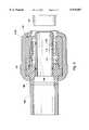
- FIG. 1is a cross-sectional elevational view of a plastic pipe repair fitting constructed according to a preferred embodiment of the present invention.
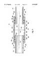
- FIG. 2is a cross-sectional elevational view of the plastic pipe repair fitting shown in FIG. 1, with two stab fittings connecting the repair fitting to pipeline ends.
- FIG. 3is an exploded view of the stab fitting shown in FIG. 2.
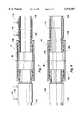
- FIG. 4is a cross-sectional elevational view of a plastic pipe repair fitting, with the repair fitting connected to the pipeline ends by one fusion joint and one stab fitting.
- FIG. 5is a cross-sectional elevational view of a plastic pipe repair fitting, with the repair fitting connected to the pipeline ends by two fusion joints.
- FIG. 6is a cross-sectional elevational view of a plastic pipe repair fitting, with a cylindrical hub to connect the repair fitting cylinders.
- FIG. 7is a partial cross-sectional elevation view of a plastic pipe repair fitting connected to the pipeline ends by electrofusion joints.
- FIG. 8is a partial cross-sectional elevation view of a pipe repair fitting connected to the pipeline ends by glue joints.
- a telescoping repair fitting 10is provided for installation between two ends of a plastic pipeline 12A and 12B.
- the repair fitting 10itself may be assembled away from the pipeline, such as in a shop, and may be easily transported for installation.
- the repair fitting 10is used to replace a damaged section of pipeline.
- the damaged portion of the pipelineis cut away from the pipeline, forming pipeline ends 12A and 12B.
- the repair fitting 10is connected to pipeline ends 12A and 12B with two stab fittings 210A and 210B.
- Stab fittingsare couplers designed to be manually inserted onto the end of a length of plastic pipe.
- One type of preferred stab fittings 210A and 210Bare those disclosed by Assignee in U.S. Pat. No. 5,692,785 and pending application Ser. No. 08/784,499 which is incorporated herein by reference.
- a first piston extension end 20Ais connected to second pipeline end 12A with one stab fitting 210A.
- a second piston extension end 16Bis connected to a second pipeline end 12B by a fusion joint 60.
- both piston extension ends 20A and 20Bform a fusion joints 60 with the first and second pipeline ends 12A and 12B, respectively.
- first piston 14Ais disposed in first cylinder 30A and second piston 14B is disposed in second cylinder 30B.
- the repair fittingis produced from two identical cylinders 30A and 30B.
- Each cylinderincludes an open top 36A and 36B, respectively, and a bottom 38A and 38B, respectively, having an opening therethrough.
- the cylinders 30A and 30Bare joined together at their open ends.
- O-ring grooves 22A and 22Bthere are O-ring grooves 22A and 22B in piston heads 16A and 16B, respectively.
- Resilient O-rings 24A and 24Bare positioned in O-ring grooves 22A and 22B before the piston heads 16A and 16B are moved into the cylinders 30A and 30B.
- the cylinder inner walls 34A and 34Bhave the same diameter.
- the cylinder outer walls 32A and 32Balso have the same diameter.
- the O-rings 24Aprovide a fluid barrier between: (1) the volume in the cylinder 30A between piston head 16A and top rim 42A, and (2) the volume between piston head 16A and cylinder bottom shoulder 40A.
- the O-rings 24Bprovide a similar seal in cylinder 30B. When installed, the O-rings 24A and 24B allow the pistons 14A and 14B to move and still maintain the above-mentioned liquid or gas barrier. After the repair fitting 10 is installed, the piston heads 16A and 16B are not moved.
- First cylinder top rim 42A and second cylinder top rim 42Bare fused together to form a cylinder-to-cylinder fluid-tight fusion joint 50.
- the fusion jointmay be formed a number of ways. In the butt fusion process, a heating element is brought in contact with the faces of the piston ends.
- the fusion joint 50is formed by: (1) butting the top rims 42A and 42B together, such that centerlines 44A and 44B of the cylinders 30A and 30B coincide; and (2) heating the cylinder outer walls 32A and 32B at the intersection of the abutting top rims 42A and 42B.
- Other types of joints that might be usedare mechanical compression joints, elastomeric joints, and chemical solvent joints.
- the fluid seal at fusion joint 50 and the liquid and gas barrier provided by the O-rings 24A and 24Bprevent any liquid or gas located in the volume between the piston heads 16A and 16B from escaping to the outside environment.
- the fusion joint 50also acts as a support rib for the housing of the repair fitting.
- the fusion joint 50On the inside of the housing, the fusion joint 50 also creates a stop or divider for the travel of each piston in the retracted position.
- piston extension ends 20A and 20Bare connected to the pipeline ends 12A and 12B by stab fittings 210A and 210B.
- the stab fittingsprovide a fluid-tight, sealed connection between (1) the pipeline end 12A and the piston extension end 20A, and (2) the pipeline end 12B and the piston extension end 20B.
- a fluid sealed connectionis provided between the pipeline ends 12A and 12B.
- FIG. 3illustrates an enlarged sectional view of the connection with pipeline 12B.
- Piston extension end 20Bis connected with stab fitting 210B by fusion joint 106.
- Pipeline end 12Bis secured in fitting 210A.
- the stab fitting 210B shown in FIG. 3is the stab fitting disclosed in U.S. Pat. No. 5,692,785 and in co-pending application Ser. No. 08/784,499, now U.S. Pat. No. 5,791,698, which are incorporated herein by reference.
- a straight tubular stiffener 100extends through the entire length of the coupler fitting 210B.
- Tubular stiffener 100has an external diameter slightly smaller than the internal diameter of plastic pipes 12B to permit the pipe to be pushed over the stiffener.
- Extending outward radially from the body of the stiffener 100is a radial hub portion 102.
- a protective outer body 110surrounds the shell 104 and hub 102 106 and serves to hold the shell and hub in position. Adjacent the hub portion 102 is torodial follower 112. Adjacent the follower 112 is front boot seal 116. Adjacent the seal 116 is hollow gripper 120.
- the first piston extension end 20Ais sealably connected to first pipeline end 12A by stab fitting 210A, as described above for FIG. 3.
- the second piston extension end 20Bis sealably connected to second pipeline end 12B by a piston extension end-pipeline end fusion joint 60.
- the fusion joint 60may be formed a number of ways. In the preferred butt fusion process, a heating element is brought in contact with the faces of the piston end 20B and pipeline end 12B.
- an electrofusion jointmay be formed by: (1) butting the second extension end 20B to second pipeline end 12B; and (2) heating the circumferential intersection of the second extension end 20B and the second pipeline end 12B until a fusion joint is formed.
- both piston extension ends 20A and 20Bare sealably connected to pipeline ends 12A and 12B by fusion joints 60. Once the damaged portion of the pipeline has been removed, the repair fitting 10 is inserted and the ends are butt fused to the pipeline ends.
- FIG. 6an alternate embodiment is shown for repair fitting 10, in which the cylinders 30A and 30B of the fitting are sealably connected using a cylindrical hub 70.
- the diameter of the hub inner walls 72A and 72Bis slightly larger than the diameter of the cylinder outer walls 32A and 32B.
- the hub inner wall 72Bhas the same diameter as the hub inner wall 72A.
- the cylinder outer wall 32Ahas the same diameter as the cylinder outer wall 32B.
- All materials used in the repair fitting 10may be made from plastic, except for the O-rings.
- FIG. 7illustrates a further alternate embodiment of the repair fitting of the present invention.
- Each piston end 20A and 20Bis connected by an electrofusion joint 140 and 142.
- the piston extension 20A and 20Bis butted up against the pipeline ends 12A and 12B such that the center lines or axis are aligned.
- the electrofusion joints 140 and 142contain conductors 144 (seen in the sectional view) which is supplied with electrical energy through leads 146. Accordingly, the electrofusion joints 140 and 142 cause the piston ends and the pipeline ends to heat so that the outer circumferences form a fluid tight joint.
- FIG. 8shows a further alternate embodiment of the plastic pipe repair fitting.
- Each piston end 20A and 20Bwill be joined with a pipeline end 12A and 12B, respectively, by fluid joints 150 and 152.
- the piston extensions 20A and 20Bare butted together and brought into alignment with the pipeline ends 12A and 12B. Glue or other adhesive is applied between the joint 150 and pipeline end 12B and between joint 152 and pipeline end 12B. A fluid tight seal is thus created.
Landscapes
- Engineering & Computer Science (AREA)
- General Engineering & Computer Science (AREA)
- Mechanical Engineering (AREA)
- Lining Or Joining Of Plastics Or The Like (AREA)
Abstract
Description
______________________________________ U.S. Pat. No. INVENTOR(S) TITLE ______________________________________ 4,804,209 Fischer PLUMMER'S UNION 4,810,008 Brodie METHOD AND APPARATUS FOR REPAIRING LAWN SPRINKLER SYSTEMS 4,946,213 Guest TUBE COUPLINGS 5,024,469 Aitken et al. ADJUSTABLE LENGTH PIPING UNION 5,082,313 Stine EXPANSION JOINT FOR CONDUIT FOR CABLES 5,442,482 Baddour WELDLESS PIPE REPAIR APPARATUS AND METHOD 5,509,698 Habicht AXIALLY EXTENDIBLE CONDUIT 5,692,785 Wartluft et al. PLASTIC PIPE COUPLER WITH INTERNAL SEALER ______________________________________
Claims (5)
Priority Applications (1)
| Application Number | Priority Date | Filing Date | Title |
|---|---|---|---|
| US09/087,072US5975587A (en) | 1996-04-01 | 1998-05-29 | Plastic pipe repair fitting and connection apparatus |
Applications Claiming Priority (3)
| Application Number | Priority Date | Filing Date | Title |
|---|---|---|---|
| US08/626,024US5692785A (en) | 1995-11-29 | 1996-04-01 | Plastic pipe coupler with internal sealer |
| US08/784,499US5791698A (en) | 1995-11-29 | 1997-01-17 | Plastic pipe coupler with internal sealer |
| US09/087,072US5975587A (en) | 1996-04-01 | 1998-05-29 | Plastic pipe repair fitting and connection apparatus |
Related Parent Applications (1)
| Application Number | Title | Priority Date | Filing Date |
|---|---|---|---|
| US08/784,499Continuation-In-PartUS5791698A (en) | 1995-11-29 | 1997-01-17 | Plastic pipe coupler with internal sealer |
Publications (1)
| Publication Number | Publication Date |
|---|---|
| US5975587Atrue US5975587A (en) | 1999-11-02 |
Family
ID=46254086
Family Applications (1)
| Application Number | Title | Priority Date | Filing Date |
|---|---|---|---|
| US09/087,072Expired - LifetimeUS5975587A (en) | 1996-04-01 | 1998-05-29 | Plastic pipe repair fitting and connection apparatus |
Country Status (1)
| Country | Link |
|---|---|
| US (1) | US5975587A (en) |
Cited By (92)
| Publication number | Priority date | Publication date | Assignee | Title |
|---|---|---|---|---|
| US6318761B1 (en)* | 1999-11-26 | 2001-11-20 | Duane D. Robertson | Replacement fitting for rigid, plastic pipes |
| US6422574B1 (en)* | 2000-05-10 | 2002-07-23 | Charles J. Mooklar | Water seal for quick repair and flow control |
| US6494493B1 (en)* | 2001-08-17 | 2002-12-17 | Bradford G. Baruh | Device and method for coupling pipes |
| US6497433B1 (en)* | 1999-08-20 | 2002-12-24 | Ti Group Automotive Systems Corporation | Coupling assemblies for providing fluid connection |
| US20040021112A1 (en)* | 2000-03-06 | 2004-02-05 | Joseph Carpenter | Control valve having moveable outlet |
| US6692035B2 (en) | 2001-08-17 | 2004-02-17 | Bradford G. Baruh | Device and method for coupling pipes |
| US20040188014A1 (en)* | 2001-07-05 | 2004-09-30 | Kjell Johanson | Method and device for jointing of cores |
| US20040201214A1 (en)* | 2003-04-11 | 2004-10-14 | Dwws, Llc | Thermal expansion connection for rigid pipes |
| US20040232693A1 (en)* | 2001-09-20 | 2004-11-25 | Olivier Legeay | Connecting device with secure mounting |
| US20050002439A1 (en)* | 2003-04-14 | 2005-01-06 | Blichmann John R. | In-line thermometer |
| US6877777B1 (en) | 2002-04-16 | 2005-04-12 | Continental Industries, Inc. | Insertion sleeve and stiffener for a pipe coupling |
| GB2408277A (en)* | 2002-07-19 | 2005-05-25 | Enventure Global Technology | Protective sleeve for threaded connections for expandable liner hanger |
| US20050123355A1 (en)* | 2003-12-03 | 2005-06-09 | Kolenski Gary J. | Method of installing a fibreglass pipeline |
| US20050151369A1 (en)* | 2001-08-17 | 2005-07-14 | Baruh Bradford G. | Device and method for coupling pipes |
| US20050183784A1 (en)* | 2004-02-24 | 2005-08-25 | Fails Sidney T. | Pipe repair tool |
| US6976541B2 (en) | 2000-09-18 | 2005-12-20 | Shell Oil Company | Liner hanger with sliding sleeve valve |
| US7011161B2 (en) | 1998-12-07 | 2006-03-14 | Shell Oil Company | Structural support |
| US7021390B2 (en) | 1998-12-07 | 2006-04-04 | Shell Oil Company | Tubular liner for wellbore casing |
| US7040396B2 (en) | 1999-02-26 | 2006-05-09 | Shell Oil Company | Apparatus for releasably coupling two elements |
| US7044218B2 (en) | 1998-12-07 | 2006-05-16 | Shell Oil Company | Apparatus for radially expanding tubular members |
| US7048067B1 (en) | 1999-11-01 | 2006-05-23 | Shell Oil Company | Wellbore casing repair |
| US7055608B2 (en) | 1999-03-11 | 2006-06-06 | Shell Oil Company | Forming a wellbore casing while simultaneously drilling a wellbore |
| US7077211B2 (en) | 1998-12-07 | 2006-07-18 | Shell Oil Company | Method of creating a casing in a borehole |
| US7100684B2 (en) | 2000-07-28 | 2006-09-05 | Enventure Global Technology | Liner hanger with standoffs |
| US7100685B2 (en) | 2000-10-02 | 2006-09-05 | Enventure Global Technology | Mono-diameter wellbore casing |
| US20060226391A1 (en)* | 2005-04-11 | 2006-10-12 | Kramer Kenneth C | Water valve with expanding fittings |
| US7147053B2 (en) | 1998-12-07 | 2006-12-12 | Shell Oil Company | Wellhead |
| US7152631B1 (en) | 2004-02-24 | 2006-12-26 | Fails Sidney T | Pipe repair tool |
| US7168496B2 (en) | 2001-07-06 | 2007-01-30 | Eventure Global Technology | Liner hanger |
| US7168499B2 (en) | 1998-11-16 | 2007-01-30 | Shell Oil Company | Radial expansion of tubular members |
| US7172024B2 (en) | 2000-10-02 | 2007-02-06 | Shell Oil Company | Mono-diameter wellbore casing |
| US7185710B2 (en) | 1998-12-07 | 2007-03-06 | Enventure Global Technology | Mono-diameter wellbore casing |
| US7195064B2 (en) | 1998-12-07 | 2007-03-27 | Enventure Global Technology | Mono-diameter wellbore casing |
| US7231985B2 (en) | 1998-11-16 | 2007-06-19 | Shell Oil Company | Radial expansion of tubular members |
| US7234531B2 (en) | 1999-12-03 | 2007-06-26 | Enventure Global Technology, Llc | Mono-diameter wellbore casing |
| US7240728B2 (en) | 1998-12-07 | 2007-07-10 | Shell Oil Company | Expandable tubulars with a radial passage and wall portions with different wall thicknesses |
| US7243731B2 (en) | 2001-08-20 | 2007-07-17 | Enventure Global Technology | Apparatus for radially expanding tubular members including a segmented expansion cone |
| US7258168B2 (en) | 2001-07-27 | 2007-08-21 | Enventure Global Technology L.L.C. | Liner hanger with slip joint sealing members and method of use |
| US7290605B2 (en) | 2001-12-27 | 2007-11-06 | Enventure Global Technology | Seal receptacle using expandable liner hanger |
| US7290616B2 (en) | 2001-07-06 | 2007-11-06 | Enventure Global Technology, L.L.C. | Liner hanger |
| US7308755B2 (en) | 2003-06-13 | 2007-12-18 | Shell Oil Company | Apparatus for forming a mono-diameter wellbore casing |
| US7325602B2 (en) | 2000-10-02 | 2008-02-05 | Shell Oil Company | Method and apparatus for forming a mono-diameter wellbore casing |
| US20080048435A1 (en)* | 2006-07-10 | 2008-02-28 | Sabastian Kelly G | Pipe coupling and clamp and method of application |
| US7350563B2 (en) | 1999-07-09 | 2008-04-01 | Enventure Global Technology, L.L.C. | System for lining a wellbore casing |
| US7360591B2 (en) | 2002-05-29 | 2008-04-22 | Enventure Global Technology, Llc | System for radially expanding a tubular member |
| US7363984B2 (en) | 1998-12-07 | 2008-04-29 | Enventure Global Technology, Llc | System for radially expanding a tubular member |
| US7377326B2 (en) | 2002-08-23 | 2008-05-27 | Enventure Global Technology, L.L.C. | Magnetic impulse applied sleeve method of forming a wellbore casing |
| US7383889B2 (en) | 2001-11-12 | 2008-06-10 | Enventure Global Technology, Llc | Mono diameter wellbore casing |
| US20080155745A1 (en)* | 2007-01-03 | 2008-07-03 | Eric Burr | Bathtub waste and overflow assembly |
| US7398832B2 (en) | 2002-06-10 | 2008-07-15 | Enventure Global Technology, Llc | Mono-diameter wellbore casing |
| US7404444B2 (en) | 2002-09-20 | 2008-07-29 | Enventure Global Technology | Protective sleeve for expandable tubulars |
| US7410000B2 (en) | 2001-01-17 | 2008-08-12 | Enventure Global Technology, Llc. | Mono-diameter wellbore casing |
| US7416027B2 (en) | 2001-09-07 | 2008-08-26 | Enventure Global Technology, Llc | Adjustable expansion cone assembly |
| US7424918B2 (en) | 2002-08-23 | 2008-09-16 | Enventure Global Technology, L.L.C. | Interposed joint sealing layer method of forming a wellbore casing |
| US7438133B2 (en) | 2003-02-26 | 2008-10-21 | Enventure Global Technology, Llc | Apparatus and method for radially expanding and plastically deforming a tubular member |
| US20080272594A1 (en)* | 2005-10-19 | 2008-11-06 | Guy Malcolm Phillipps | Slip type pipe joint |
| US20080309067A1 (en)* | 2007-06-14 | 2008-12-18 | Fazakerly William B | Repair pipe fittings |
| US7503393B2 (en) | 2003-01-27 | 2009-03-17 | Enventure Global Technology, Inc. | Lubrication system for radially expanding tubular members |
| US20090079186A1 (en)* | 2007-09-24 | 2009-03-26 | Honeywell International, Inc. | Flexible fitting for rigid tubing assembly |
| US7513313B2 (en) | 2002-09-20 | 2009-04-07 | Enventure Global Technology, Llc | Bottom plug for forming a mono diameter wellbore casing |
| US7516790B2 (en) | 1999-12-03 | 2009-04-14 | Enventure Global Technology, Llc | Mono-diameter wellbore casing |
| US7552776B2 (en) | 1998-12-07 | 2009-06-30 | Enventure Global Technology, Llc | Anchor hangers |
| US7571774B2 (en) | 2002-09-20 | 2009-08-11 | Eventure Global Technology | Self-lubricating expansion mandrel for expandable tubular |
| US7603758B2 (en) | 1998-12-07 | 2009-10-20 | Shell Oil Company | Method of coupling a tubular member |
| US7712522B2 (en) | 2003-09-05 | 2010-05-11 | Enventure Global Technology, Llc | Expansion cone and system |
| US7740076B2 (en) | 2002-04-12 | 2010-06-22 | Enventure Global Technology, L.L.C. | Protective sleeve for threaded connections for expandable liner hanger |
| US7739917B2 (en) | 2002-09-20 | 2010-06-22 | Enventure Global Technology, Llc | Pipe formability evaluation for expandable tubulars |
| US7775290B2 (en) | 2003-04-17 | 2010-08-17 | Enventure Global Technology, Llc | Apparatus for radially expanding and plastically deforming a tubular member |
| USD623126S1 (en) | 2010-02-09 | 2010-09-07 | Continental Industries, Inc. | Battery, switch and voltage indicator device |
| US7793721B2 (en) | 2003-03-11 | 2010-09-14 | Eventure Global Technology, Llc | Apparatus for radially expanding and plastically deforming a tubular member |
| US7819185B2 (en) | 2004-08-13 | 2010-10-26 | Enventure Global Technology, Llc | Expandable tubular |
| US7886831B2 (en) | 2003-01-22 | 2011-02-15 | Enventure Global Technology, L.L.C. | Apparatus for radially expanding and plastically deforming a tubular member |
| US7918284B2 (en) | 2002-04-15 | 2011-04-05 | Enventure Global Technology, L.L.C. | Protective sleeve for threaded connections for expandable liner hanger |
| AU2006303813B2 (en)* | 2005-10-19 | 2011-07-07 | Norma Pacific Pty Ltd | A slip type pipe joint |
| CN102359684A (en)* | 2011-10-13 | 2012-02-22 | 王仕才 | Fast connecting pipe fitting for plastic pipes |
| USD666976S1 (en) | 2011-08-10 | 2012-09-11 | Continental Industries, Inc. | Cathodic protection mold magnet assembly |
| CN103002695A (en)* | 2011-09-16 | 2013-03-27 | 中国石油天然气股份有限公司 | Electronic device's sealed cabin body in pipeline operation equipment |
| US20140008911A1 (en)* | 2012-07-06 | 2014-01-09 | Juergen Hartmann | Coupling device |
| US8764066B1 (en)* | 2012-09-21 | 2014-07-01 | Tyler S. Rice | Expansion coupling system |
| US20140374459A1 (en)* | 2011-10-06 | 2014-12-25 | Japan Agency For Marine-Earth Science And Technology | Fusion cutting device |
| US8991830B2 (en) | 2009-10-06 | 2015-03-31 | Prinsco, Inc. | Heat-fusible gasket and method of manufacture |
| WO2015085970A1 (en)* | 2013-12-09 | 2015-06-18 | Solutec Ingeniería S A S | Expansion coupling for variable-length pipes |
| CN104763855A (en)* | 2015-02-28 | 2015-07-08 | 美钻能源科技(上海)有限公司 | Adjustable pipe connection device |
| US20160076680A1 (en)* | 2014-09-11 | 2016-03-17 | Hamilton Sundstrand Corporation | Weldless transfer tube assembly |
| US20160279866A1 (en)* | 2015-03-25 | 2016-09-29 | Milliken Infrastructure Solutions, Llc | Method for repair of polyolefin pipes and structures |
| USD777547S1 (en) | 2013-03-22 | 2017-01-31 | Hubbell Incorporated | Handle clamp for an exothermic welding mold |
| WO2018013432A1 (en)* | 2016-07-12 | 2018-01-18 | Hubbell Incorporated | Pipe fittings |
| US10072783B2 (en) | 2013-12-19 | 2018-09-11 | Reliance Worldwide Corporation (Aust.) Pty. Ltd. | Pipe connection fitting |
| US10578235B2 (en) | 2013-03-26 | 2020-03-03 | Reliance Worldwide Corporation (Aust.) Pty. Ltd. | Tube coupling |
| US10738999B2 (en) | 2017-10-03 | 2020-08-11 | Hubbell Incorporated | Trigger devices for exothermix welds |
| US11168817B2 (en)* | 2017-04-12 | 2021-11-09 | Weatherford Technology Holdings, Llc | Shunt tube connection assembly |
| US11229970B2 (en) | 2017-08-21 | 2022-01-25 | Hubbell Incorporated | Handle for exothermic mold with spring connectors |
Citations (26)
| Publication number | Priority date | Publication date | Assignee | Title |
|---|---|---|---|---|
| US982836A (en)* | 1910-02-17 | 1911-01-31 | Henry P Ley | Extension-pipe. |
| US1363974A (en)* | 1920-12-28 | Expansion pipe-joint | ||
| US2461828A (en)* | 1946-05-13 | 1949-02-15 | Lawrence E Ostrom | Extension joint |
| US2739829A (en)* | 1950-08-05 | 1956-03-27 | American Viscose Corp | Plastic pipe joint |
| US2785910A (en)* | 1955-05-05 | 1957-03-19 | Amercoat Corp | Molded joint for plastic tubes with latch |
| US3542402A (en)* | 1969-04-02 | 1970-11-24 | Catalyst Research Corp | Joining articles of thermoplastic resins |
| US3594021A (en)* | 1970-01-27 | 1971-07-20 | Genova Products | Expansion joint |
| US3826521A (en)* | 1972-10-30 | 1974-07-30 | P Wilhelmsen | Glued replacement unit for repairing ruptured pipe |
| US3968195A (en)* | 1974-06-17 | 1976-07-06 | Marilyn Bishop | Method for making sterile connections |
| US4049480A (en)* | 1975-10-10 | 1977-09-20 | Nipak, Inc. | Method and apparatus for forming a joint in a confined space between two abutting ends of conduit liners |
| US4229025A (en)* | 1978-04-25 | 1980-10-21 | Perfection Corporation | Stab-type coupling |
| US4386796A (en)* | 1981-07-27 | 1983-06-07 | R. W. Lyall Co., Inc. | Pipe repair coupling |
| US4565393A (en)* | 1982-11-05 | 1986-01-21 | Ameron Inc. | Pipe joint |
| US4687232A (en)* | 1985-12-27 | 1987-08-18 | Zimmerman Harry M | Pipe slip joint system |
| US4804209A (en)* | 1987-10-20 | 1989-02-14 | Fischer Kevin H | Plummer's union |
| US4810008A (en)* | 1987-06-22 | 1989-03-07 | Scott Brodie | Method and apparatus for repairing lawn sprinkler systems |
| US4836581A (en)* | 1986-08-11 | 1989-06-06 | Societe Generale Pour Les Techniques | Device for making a sealed connection |
| US4932686A (en)* | 1989-07-13 | 1990-06-12 | General Motors Corporation | Telescoping connector for a fluid coupling assembly |
| US4946213A (en)* | 1988-03-25 | 1990-08-07 | Guest John D | Tube couplings |
| US5024469A (en)* | 1990-02-23 | 1991-06-18 | Aitken W Sidney | Adjustable length piping union |
| US5082313A (en)* | 1989-09-29 | 1992-01-21 | Donald Bryant | Cut-in repair coupling |
| US5125690A (en)* | 1989-12-15 | 1992-06-30 | Metcal, Inc. | Pipe joining system and method |
| US5141258A (en)* | 1990-04-24 | 1992-08-25 | Henkels & Mccoy, Inc. | Expansion joint for conduit for cables |
| US5433482A (en)* | 1993-08-16 | 1995-07-18 | Oceaneering International, Inc. | Weldless pipe repair apparatus and method |
| US5509698A (en)* | 1995-03-03 | 1996-04-23 | Habicht; Helmut | Axially extendible conduit |
| US5692785A (en)* | 1995-11-29 | 1997-12-02 | Continental Industries, Inc. | Plastic pipe coupler with internal sealer |
- 1998
- 1998-05-29USUS09/087,072patent/US5975587A/ennot_activeExpired - Lifetime
Patent Citations (26)
| Publication number | Priority date | Publication date | Assignee | Title |
|---|---|---|---|---|
| US1363974A (en)* | 1920-12-28 | Expansion pipe-joint | ||
| US982836A (en)* | 1910-02-17 | 1911-01-31 | Henry P Ley | Extension-pipe. |
| US2461828A (en)* | 1946-05-13 | 1949-02-15 | Lawrence E Ostrom | Extension joint |
| US2739829A (en)* | 1950-08-05 | 1956-03-27 | American Viscose Corp | Plastic pipe joint |
| US2785910A (en)* | 1955-05-05 | 1957-03-19 | Amercoat Corp | Molded joint for plastic tubes with latch |
| US3542402A (en)* | 1969-04-02 | 1970-11-24 | Catalyst Research Corp | Joining articles of thermoplastic resins |
| US3594021A (en)* | 1970-01-27 | 1971-07-20 | Genova Products | Expansion joint |
| US3826521A (en)* | 1972-10-30 | 1974-07-30 | P Wilhelmsen | Glued replacement unit for repairing ruptured pipe |
| US3968195A (en)* | 1974-06-17 | 1976-07-06 | Marilyn Bishop | Method for making sterile connections |
| US4049480A (en)* | 1975-10-10 | 1977-09-20 | Nipak, Inc. | Method and apparatus for forming a joint in a confined space between two abutting ends of conduit liners |
| US4229025A (en)* | 1978-04-25 | 1980-10-21 | Perfection Corporation | Stab-type coupling |
| US4386796A (en)* | 1981-07-27 | 1983-06-07 | R. W. Lyall Co., Inc. | Pipe repair coupling |
| US4565393A (en)* | 1982-11-05 | 1986-01-21 | Ameron Inc. | Pipe joint |
| US4687232A (en)* | 1985-12-27 | 1987-08-18 | Zimmerman Harry M | Pipe slip joint system |
| US4836581A (en)* | 1986-08-11 | 1989-06-06 | Societe Generale Pour Les Techniques | Device for making a sealed connection |
| US4810008A (en)* | 1987-06-22 | 1989-03-07 | Scott Brodie | Method and apparatus for repairing lawn sprinkler systems |
| US4804209A (en)* | 1987-10-20 | 1989-02-14 | Fischer Kevin H | Plummer's union |
| US4946213A (en)* | 1988-03-25 | 1990-08-07 | Guest John D | Tube couplings |
| US4932686A (en)* | 1989-07-13 | 1990-06-12 | General Motors Corporation | Telescoping connector for a fluid coupling assembly |
| US5082313A (en)* | 1989-09-29 | 1992-01-21 | Donald Bryant | Cut-in repair coupling |
| US5125690A (en)* | 1989-12-15 | 1992-06-30 | Metcal, Inc. | Pipe joining system and method |
| US5024469A (en)* | 1990-02-23 | 1991-06-18 | Aitken W Sidney | Adjustable length piping union |
| US5141258A (en)* | 1990-04-24 | 1992-08-25 | Henkels & Mccoy, Inc. | Expansion joint for conduit for cables |
| US5433482A (en)* | 1993-08-16 | 1995-07-18 | Oceaneering International, Inc. | Weldless pipe repair apparatus and method |
| US5509698A (en)* | 1995-03-03 | 1996-04-23 | Habicht; Helmut | Axially extendible conduit |
| US5692785A (en)* | 1995-11-29 | 1997-12-02 | Continental Industries, Inc. | Plastic pipe coupler with internal sealer |
Cited By (144)
| Publication number | Priority date | Publication date | Assignee | Title |
|---|---|---|---|---|
| US7357190B2 (en) | 1998-11-16 | 2008-04-15 | Shell Oil Company | Radial expansion of tubular members |
| US7231985B2 (en) | 1998-11-16 | 2007-06-19 | Shell Oil Company | Radial expansion of tubular members |
| US7168499B2 (en) | 1998-11-16 | 2007-01-30 | Shell Oil Company | Radial expansion of tubular members |
| US7246667B2 (en) | 1998-11-16 | 2007-07-24 | Shell Oil Company | Radial expansion of tubular members |
| US7270188B2 (en) | 1998-11-16 | 2007-09-18 | Shell Oil Company | Radial expansion of tubular members |
| US7275601B2 (en) | 1998-11-16 | 2007-10-02 | Shell Oil Company | Radial expansion of tubular members |
| US7108072B2 (en) | 1998-11-16 | 2006-09-19 | Shell Oil Company | Lubrication and self-cleaning system for expansion mandrel |
| US7299881B2 (en) | 1998-11-16 | 2007-11-27 | Shell Oil Company | Radial expansion of tubular members |
| US7363984B2 (en) | 1998-12-07 | 2008-04-29 | Enventure Global Technology, Llc | System for radially expanding a tubular member |
| US7077211B2 (en) | 1998-12-07 | 2006-07-18 | Shell Oil Company | Method of creating a casing in a borehole |
| US7434618B2 (en) | 1998-12-07 | 2008-10-14 | Shell Oil Company | Apparatus for expanding a tubular member |
| US7419009B2 (en) | 1998-12-07 | 2008-09-02 | Shell Oil Company | Apparatus for radially expanding and plastically deforming a tubular member |
| US7195061B2 (en) | 1998-12-07 | 2007-03-27 | Shell Oil Company | Apparatus for expanding a tubular member |
| US7195064B2 (en) | 1998-12-07 | 2007-03-27 | Enventure Global Technology | Mono-diameter wellbore casing |
| US7357188B1 (en) | 1998-12-07 | 2008-04-15 | Shell Oil Company | Mono-diameter wellbore casing |
| US7198100B2 (en) | 1998-12-07 | 2007-04-03 | Shell Oil Company | Apparatus for expanding a tubular member |
| US7185710B2 (en) | 1998-12-07 | 2007-03-06 | Enventure Global Technology | Mono-diameter wellbore casing |
| US7174964B2 (en) | 1998-12-07 | 2007-02-13 | Shell Oil Company | Wellhead with radially expanded tubulars |
| US7350564B2 (en) | 1998-12-07 | 2008-04-01 | Enventure Global Technology, L.L.C. | Mono-diameter wellbore casing |
| US7011161B2 (en) | 1998-12-07 | 2006-03-14 | Shell Oil Company | Structural support |
| US7021390B2 (en) | 1998-12-07 | 2006-04-04 | Shell Oil Company | Tubular liner for wellbore casing |
| US7036582B2 (en) | 1998-12-07 | 2006-05-02 | Shell Oil Company | Expansion cone for radially expanding tubular members |
| US7216701B2 (en) | 1998-12-07 | 2007-05-15 | Shell Oil Company | Apparatus for expanding a tubular member |
| US7044218B2 (en) | 1998-12-07 | 2006-05-16 | Shell Oil Company | Apparatus for radially expanding tubular members |
| US7665532B2 (en) | 1998-12-07 | 2010-02-23 | Shell Oil Company | Pipeline |
| US7048062B2 (en) | 1998-12-07 | 2006-05-23 | Shell Oil Company | Method of selecting tubular members |
| US7240729B2 (en) | 1998-12-07 | 2007-07-10 | Shell Oil Company | Apparatus for expanding a tubular member |
| US7240728B2 (en) | 1998-12-07 | 2007-07-10 | Shell Oil Company | Expandable tubulars with a radial passage and wall portions with different wall thicknesses |
| US7159665B2 (en) | 1998-12-07 | 2007-01-09 | Shell Oil Company | Wellbore casing |
| US7147053B2 (en) | 1998-12-07 | 2006-12-12 | Shell Oil Company | Wellhead |
| US7077213B2 (en) | 1998-12-07 | 2006-07-18 | Shell Oil Company | Expansion cone for radially expanding tubular members |
| US7086475B2 (en) | 1998-12-07 | 2006-08-08 | Shell Oil Company | Method of inserting a tubular member into a wellbore |
| US7121337B2 (en) | 1998-12-07 | 2006-10-17 | Shell Oil Company | Apparatus for expanding a tubular member |
| US7552776B2 (en) | 1998-12-07 | 2009-06-30 | Enventure Global Technology, Llc | Anchor hangers |
| US7603758B2 (en) | 1998-12-07 | 2009-10-20 | Shell Oil Company | Method of coupling a tubular member |
| US7044221B2 (en)* | 1999-02-26 | 2006-05-16 | Shell Oil Company | Apparatus for coupling a tubular member to a preexisting structure |
| US7040396B2 (en) | 1999-02-26 | 2006-05-09 | Shell Oil Company | Apparatus for releasably coupling two elements |
| US7556092B2 (en) | 1999-02-26 | 2009-07-07 | Enventure Global Technology, Llc | Flow control system for an apparatus for radially expanding tubular members |
| US7438132B2 (en) | 1999-03-11 | 2008-10-21 | Shell Oil Company | Concentric pipes expanded at the pipe ends and method of forming |
| US7055608B2 (en) | 1999-03-11 | 2006-06-06 | Shell Oil Company | Forming a wellbore casing while simultaneously drilling a wellbore |
| US7350563B2 (en) | 1999-07-09 | 2008-04-01 | Enventure Global Technology, L.L.C. | System for lining a wellbore casing |
| US6497433B1 (en)* | 1999-08-20 | 2002-12-24 | Ti Group Automotive Systems Corporation | Coupling assemblies for providing fluid connection |
| US7048067B1 (en) | 1999-11-01 | 2006-05-23 | Shell Oil Company | Wellbore casing repair |
| US6318761B1 (en)* | 1999-11-26 | 2001-11-20 | Duane D. Robertson | Replacement fitting for rigid, plastic pipes |
| US7234531B2 (en) | 1999-12-03 | 2007-06-26 | Enventure Global Technology, Llc | Mono-diameter wellbore casing |
| US7516790B2 (en) | 1999-12-03 | 2009-04-14 | Enventure Global Technology, Llc | Mono-diameter wellbore casing |
| US20040021112A1 (en)* | 2000-03-06 | 2004-02-05 | Joseph Carpenter | Control valve having moveable outlet |
| US6945512B2 (en)* | 2000-03-06 | 2005-09-20 | Joseph Carpenter | Control valve having moveable outlet |
| US6422574B1 (en)* | 2000-05-10 | 2002-07-23 | Charles J. Mooklar | Water seal for quick repair and flow control |
| US7100684B2 (en) | 2000-07-28 | 2006-09-05 | Enventure Global Technology | Liner hanger with standoffs |
| US7172021B2 (en) | 2000-09-18 | 2007-02-06 | Shell Oil Company | Liner hanger with sliding sleeve valve |
| US6976541B2 (en) | 2000-09-18 | 2005-12-20 | Shell Oil Company | Liner hanger with sliding sleeve valve |
| US7325602B2 (en) | 2000-10-02 | 2008-02-05 | Shell Oil Company | Method and apparatus for forming a mono-diameter wellbore casing |
| US7146702B2 (en) | 2000-10-02 | 2006-12-12 | Shell Oil Company | Method and apparatus for forming a mono-diameter wellbore casing |
| US7201223B2 (en) | 2000-10-02 | 2007-04-10 | Shell Oil Company | Method and apparatus for forming a mono-diameter wellbore casing |
| US7204007B2 (en) | 2000-10-02 | 2007-04-17 | Shell Oil Company | Method and apparatus for forming a mono-diameter wellbore casing |
| US7172024B2 (en) | 2000-10-02 | 2007-02-06 | Shell Oil Company | Mono-diameter wellbore casing |
| US7172019B2 (en) | 2000-10-02 | 2007-02-06 | Shell Oil Company | Method and apparatus for forming a mono-diameter wellbore casing |
| US7363691B2 (en) | 2000-10-02 | 2008-04-29 | Shell Oil Company | Method and apparatus for forming a mono-diameter wellbore casing |
| US7363690B2 (en) | 2000-10-02 | 2008-04-29 | Shell Oil Company | Method and apparatus for forming a mono-diameter wellbore casing |
| US7100685B2 (en) | 2000-10-02 | 2006-09-05 | Enventure Global Technology | Mono-diameter wellbore casing |
| US7410000B2 (en) | 2001-01-17 | 2008-08-12 | Enventure Global Technology, Llc. | Mono-diameter wellbore casing |
| US20040188014A1 (en)* | 2001-07-05 | 2004-09-30 | Kjell Johanson | Method and device for jointing of cores |
| US7322922B2 (en)* | 2001-07-05 | 2008-01-29 | Core Link Ab | Method and device for jointing of cores |
| US7168496B2 (en) | 2001-07-06 | 2007-01-30 | Eventure Global Technology | Liner hanger |
| US7290616B2 (en) | 2001-07-06 | 2007-11-06 | Enventure Global Technology, L.L.C. | Liner hanger |
| US7258168B2 (en) | 2001-07-27 | 2007-08-21 | Enventure Global Technology L.L.C. | Liner hanger with slip joint sealing members and method of use |
| US6692035B2 (en) | 2001-08-17 | 2004-02-17 | Bradford G. Baruh | Device and method for coupling pipes |
| US20050151369A1 (en)* | 2001-08-17 | 2005-07-14 | Baruh Bradford G. | Device and method for coupling pipes |
| US6494493B1 (en)* | 2001-08-17 | 2002-12-17 | Bradford G. Baruh | Device and method for coupling pipes |
| US7243731B2 (en) | 2001-08-20 | 2007-07-17 | Enventure Global Technology | Apparatus for radially expanding tubular members including a segmented expansion cone |
| US7416027B2 (en) | 2001-09-07 | 2008-08-26 | Enventure Global Technology, Llc | Adjustable expansion cone assembly |
| US20040232693A1 (en)* | 2001-09-20 | 2004-11-25 | Olivier Legeay | Connecting device with secure mounting |
| US7559365B2 (en) | 2001-11-12 | 2009-07-14 | Enventure Global Technology, Llc | Collapsible expansion cone |
| US7383889B2 (en) | 2001-11-12 | 2008-06-10 | Enventure Global Technology, Llc | Mono diameter wellbore casing |
| US7290605B2 (en) | 2001-12-27 | 2007-11-06 | Enventure Global Technology | Seal receptacle using expandable liner hanger |
| US7740076B2 (en) | 2002-04-12 | 2010-06-22 | Enventure Global Technology, L.L.C. | Protective sleeve for threaded connections for expandable liner hanger |
| US7918284B2 (en) | 2002-04-15 | 2011-04-05 | Enventure Global Technology, L.L.C. | Protective sleeve for threaded connections for expandable liner hanger |
| US6877777B1 (en) | 2002-04-16 | 2005-04-12 | Continental Industries, Inc. | Insertion sleeve and stiffener for a pipe coupling |
| US7360591B2 (en) | 2002-05-29 | 2008-04-22 | Enventure Global Technology, Llc | System for radially expanding a tubular member |
| US7398832B2 (en) | 2002-06-10 | 2008-07-15 | Enventure Global Technology, Llc | Mono-diameter wellbore casing |
| GB2408277A (en)* | 2002-07-19 | 2005-05-25 | Enventure Global Technology | Protective sleeve for threaded connections for expandable liner hanger |
| GB2408277B (en)* | 2002-07-19 | 2007-01-10 | Enventure Global Technology | Protective sleeve for threaded connections for expandable liner hanger |
| US7424918B2 (en) | 2002-08-23 | 2008-09-16 | Enventure Global Technology, L.L.C. | Interposed joint sealing layer method of forming a wellbore casing |
| US7377326B2 (en) | 2002-08-23 | 2008-05-27 | Enventure Global Technology, L.L.C. | Magnetic impulse applied sleeve method of forming a wellbore casing |
| US7404444B2 (en) | 2002-09-20 | 2008-07-29 | Enventure Global Technology | Protective sleeve for expandable tubulars |
| US7739917B2 (en) | 2002-09-20 | 2010-06-22 | Enventure Global Technology, Llc | Pipe formability evaluation for expandable tubulars |
| US7513313B2 (en) | 2002-09-20 | 2009-04-07 | Enventure Global Technology, Llc | Bottom plug for forming a mono diameter wellbore casing |
| US7571774B2 (en) | 2002-09-20 | 2009-08-11 | Eventure Global Technology | Self-lubricating expansion mandrel for expandable tubular |
| US7886831B2 (en) | 2003-01-22 | 2011-02-15 | Enventure Global Technology, L.L.C. | Apparatus for radially expanding and plastically deforming a tubular member |
| US7503393B2 (en) | 2003-01-27 | 2009-03-17 | Enventure Global Technology, Inc. | Lubrication system for radially expanding tubular members |
| US7438133B2 (en) | 2003-02-26 | 2008-10-21 | Enventure Global Technology, Llc | Apparatus and method for radially expanding and plastically deforming a tubular member |
| US7793721B2 (en) | 2003-03-11 | 2010-09-14 | Eventure Global Technology, Llc | Apparatus for radially expanding and plastically deforming a tubular member |
| US20040201214A1 (en)* | 2003-04-11 | 2004-10-14 | Dwws, Llc | Thermal expansion connection for rigid pipes |
| US6848725B2 (en)* | 2003-04-11 | 2005-02-01 | Dwws, Llc | Thermal expansion connection for rigid pipes |
| US20050002439A1 (en)* | 2003-04-14 | 2005-01-06 | Blichmann John R. | In-line thermometer |
| US7192187B2 (en)* | 2003-04-14 | 2007-03-20 | John R Blichmann | In-line thermometer |
| US7775290B2 (en) | 2003-04-17 | 2010-08-17 | Enventure Global Technology, Llc | Apparatus for radially expanding and plastically deforming a tubular member |
| US7308755B2 (en) | 2003-06-13 | 2007-12-18 | Shell Oil Company | Apparatus for forming a mono-diameter wellbore casing |
| US7712522B2 (en) | 2003-09-05 | 2010-05-11 | Enventure Global Technology, Llc | Expansion cone and system |
| US20050123355A1 (en)* | 2003-12-03 | 2005-06-09 | Kolenski Gary J. | Method of installing a fibreglass pipeline |
| US20070017589A1 (en)* | 2004-02-24 | 2007-01-25 | Fails Sidney T | Pipe repair tool |
| US7152631B1 (en) | 2004-02-24 | 2006-12-26 | Fails Sidney T | Pipe repair tool |
| US20050183784A1 (en)* | 2004-02-24 | 2005-08-25 | Fails Sidney T. | Pipe repair tool |
| US7007719B2 (en) | 2004-02-24 | 2006-03-07 | Fails Sidney T | Pipe repair tool |
| US20060151036A1 (en)* | 2004-02-24 | 2006-07-13 | Fails Sidney T | Pipe repair tool |
| US7819185B2 (en) | 2004-08-13 | 2010-10-26 | Enventure Global Technology, Llc | Expandable tubular |
| US20060226391A1 (en)* | 2005-04-11 | 2006-10-12 | Kramer Kenneth C | Water valve with expanding fittings |
| US20080272594A1 (en)* | 2005-10-19 | 2008-11-06 | Guy Malcolm Phillipps | Slip type pipe joint |
| AU2006303813B2 (en)* | 2005-10-19 | 2011-07-07 | Norma Pacific Pty Ltd | A slip type pipe joint |
| US20080048435A1 (en)* | 2006-07-10 | 2008-02-28 | Sabastian Kelly G | Pipe coupling and clamp and method of application |
| US20080155745A1 (en)* | 2007-01-03 | 2008-07-03 | Eric Burr | Bathtub waste and overflow assembly |
| US20080309067A1 (en)* | 2007-06-14 | 2008-12-18 | Fazakerly William B | Repair pipe fittings |
| US20090079186A1 (en)* | 2007-09-24 | 2009-03-26 | Honeywell International, Inc. | Flexible fitting for rigid tubing assembly |
| US8991830B2 (en) | 2009-10-06 | 2015-03-31 | Prinsco, Inc. | Heat-fusible gasket and method of manufacture |
| USD623126S1 (en) | 2010-02-09 | 2010-09-07 | Continental Industries, Inc. | Battery, switch and voltage indicator device |
| USD666976S1 (en) | 2011-08-10 | 2012-09-11 | Continental Industries, Inc. | Cathodic protection mold magnet assembly |
| CN103002695B (en)* | 2011-09-16 | 2015-10-14 | 中国石油天然气股份有限公司 | Electronic device's sealed cabin body in pipeline operation equipment |
| CN103002695A (en)* | 2011-09-16 | 2013-03-27 | 中国石油天然气股份有限公司 | Electronic device's sealed cabin body in pipeline operation equipment |
| US20140374459A1 (en)* | 2011-10-06 | 2014-12-25 | Japan Agency For Marine-Earth Science And Technology | Fusion cutting device |
| US9511506B2 (en)* | 2011-10-06 | 2016-12-06 | Japan Agency For Marine-Earth Science And Technology | Fusion cutting device |
| CN102359684A (en)* | 2011-10-13 | 2012-02-22 | 王仕才 | Fast connecting pipe fitting for plastic pipes |
| US20140008911A1 (en)* | 2012-07-06 | 2014-01-09 | Juergen Hartmann | Coupling device |
| US9611959B2 (en)* | 2012-07-06 | 2017-04-04 | Pfw Aerospace Ag | Coupling device |
| US8764066B1 (en)* | 2012-09-21 | 2014-07-01 | Tyler S. Rice | Expansion coupling system |
| USD777547S1 (en) | 2013-03-22 | 2017-01-31 | Hubbell Incorporated | Handle clamp for an exothermic welding mold |
| USD805366S1 (en) | 2013-03-22 | 2017-12-19 | Hubbell Incorporated | Handle clamp for an exothermic welding mold |
| US10578235B2 (en) | 2013-03-26 | 2020-03-03 | Reliance Worldwide Corporation (Aust.) Pty. Ltd. | Tube coupling |
| WO2015085970A1 (en)* | 2013-12-09 | 2015-06-18 | Solutec Ingeniería S A S | Expansion coupling for variable-length pipes |
| US10072783B2 (en) | 2013-12-19 | 2018-09-11 | Reliance Worldwide Corporation (Aust.) Pty. Ltd. | Pipe connection fitting |
| US20160076680A1 (en)* | 2014-09-11 | 2016-03-17 | Hamilton Sundstrand Corporation | Weldless transfer tube assembly |
| US10066770B2 (en)* | 2014-09-11 | 2018-09-04 | Hamilton Sundstrand Corporation | Weldless transfer tube assembly |
| CN104763855A (en)* | 2015-02-28 | 2015-07-08 | 美钻能源科技(上海)有限公司 | Adjustable pipe connection device |
| US20160279866A1 (en)* | 2015-03-25 | 2016-09-29 | Milliken Infrastructure Solutions, Llc | Method for repair of polyolefin pipes and structures |
| US11060647B2 (en) | 2016-07-12 | 2021-07-13 | Hubbell Incorporated | Pipe fittings |
| WO2018013432A1 (en)* | 2016-07-12 | 2018-01-18 | Hubbell Incorporated | Pipe fittings |
| US12404961B2 (en) | 2016-07-12 | 2025-09-02 | Hubbell Incorporated | Pipe fittings |
| US11168817B2 (en)* | 2017-04-12 | 2021-11-09 | Weatherford Technology Holdings, Llc | Shunt tube connection assembly |
| AU2018251876B2 (en)* | 2017-04-12 | 2022-07-28 | Weatherford Technology Holdings, Llc | Shunt tube connection assembly |
| US11229970B2 (en) | 2017-08-21 | 2022-01-25 | Hubbell Incorporated | Handle for exothermic mold with spring connectors |
| US11724327B2 (en) | 2017-08-21 | 2023-08-15 | Hubbell Incorporated | Handle for exothermic mold with spring connectors |
| US10935239B2 (en) | 2017-10-03 | 2021-03-02 | Hubbell Incorporated | Trigger devices for exothermic welds |
| US11441776B2 (en) | 2017-10-03 | 2022-09-13 | Hubbell Incorporated | Trigger devices for exothermic welds |
| US10738999B2 (en) | 2017-10-03 | 2020-08-11 | Hubbell Incorporated | Trigger devices for exothermix welds |
Similar Documents
| Publication | Publication Date | Title |
|---|---|---|
| US5975587A (en) | Plastic pipe repair fitting and connection apparatus | |
| US4687232A (en) | Pipe slip joint system | |
| US4013309A (en) | Repair kit for plastic pipe | |
| US4997214A (en) | Transition fitting | |
| FI78633C (en) | ANORDNING ATT ANVAENDAS VID HOPSVETSNING AV ROER. | |
| AU628219B2 (en) | Pipe joint | |
| US3968552A (en) | Method and apparatus for forming plastic lined junction in lined pipe | |
| US4718698A (en) | Apparatus and method of forming fusion welded butt joint between thermoplastic pipe sections | |
| US5088774A (en) | Coupling for interconnection of coaxial tubing | |
| US4398754A (en) | Electrically insulated pipe coupling and method for making the same | |
| FI75659B (en) | ROERKOPPLING FOER ISOLERADE ROER OCH FOERFARANDE FOER DESS INSTALLERING. | |
| US5988691A (en) | Fluid pipelines | |
| US4039210A (en) | Coupling adapter for plastic pipe | |
| RU2529293C2 (en) | Connecting unit | |
| US2668066A (en) | Coupling means for tubular casing | |
| CN112074682A (en) | Apparatus and method for welding lined pipes | |
| US3907049A (en) | Lined pipe and method of making same | |
| RU2157945C2 (en) | Apparatus for sealed fastening on at least one cylindrical member | |
| CA2114304A1 (en) | Safety flow restrictor for expansion joints | |
| WO1997048935A1 (en) | A high temperature inline expansion joint | |
| US5690148A (en) | Closure fitting and flexibility support assembly for double-containment piping systems | |
| CA2267273A1 (en) | Pipe coupling device | |
| CA1137136A (en) | Method and apparatus for forming plastic lined couplings in lined pipe | |
| LT3292B (en) | Device for essembling of pipework and using the same | |
| US4662660A (en) | Weldless high-pressure pipe fitting |
Legal Events
| Date | Code | Title | Description |
|---|---|---|---|
| AS | Assignment | Owner name:CONTINENTAL INDUSTRIES, INC., OKLAHOMA Free format text:ASSIGNMENT OF ASSIGNORS INTEREST;ASSIGNORS:WOOD, TIMOTHY F.;BENTLEY, DAVID E.;WARTLUFT, DONALD W.;REEL/FRAME:009220/0584 Effective date:19980529 | |
| STCF | Information on status: patent grant | Free format text:PATENTED CASE | |
| FPAY | Fee payment | Year of fee payment:4 | |
| AS | Assignment | Owner name:ABLECO FINANCE LLC, NEW YORK Free format text:SECURITY INTEREST;ASSIGNOR:CONTINENTIAL INDUSTRIES, INC.;REEL/FRAME:014523/0321 Effective date:20040331 | |
| AS | Assignment | Owner name:CONGRESS FINANCIAL CORPORATION, AS AGENT, NEW YORK Free format text:SECURITY INTEREST;ASSIGNOR:CONTINENTAL INDUSTRIES, INC.;REEL/FRAME:015355/0868 Effective date:20040331 | |
| AS | Assignment | Owner name:CANPARTNERS INVESTMENTS IV, LLC, AS COLLATERAL AGE Free format text:ASSIGNMENT OF SECURITY INTEREST;ASSIGNOR:ABLECO FINANCE LLC;REEL/FRAME:015334/0172 Effective date:20041029 | |
| FPAY | Fee payment | Year of fee payment:8 | |
| AS | Assignment | Owner name:STEEL PARTNERS II LIQUIDATING SERIES TRUST - SERIE Free format text:SECURITY AGREEMENT;ASSIGNOR:STEEL PARTNERS II, L.P.;REEL/FRAME:023741/0717 Effective date:20090715 | |
| AS | Assignment | Owner name:ABLECO, L.L.C., AS AGENT, NEW YORK Free format text:PATENT COLLATERAL ASSIGNMENT AND SECURITY AGREEMENT;ASSIGNOR:CONTINENTAL INDUSTRIES, INC.;REEL/FRAME:025153/0332 Effective date:20101015 | |
| FPAY | Fee payment | Year of fee payment:12 | |
| AS | Assignment | Owner name:CONTINENTAL INDUSTRIES, INC., OKLAHOMA Free format text:RELEASE OF PATENT COLLATERAL ASSIGNMENTS;ASSIGNOR:ABELCO, L.L.C.;REEL/FRAME:029300/0017 Effective date:20121108 Owner name:CONTINENTAL INDUSTRIES, INC., OKLAHOMA Free format text:RELEASE OF SECURITY INTEREST IN PATENTS;ASSIGNOR:WELLS FARGO BANK, NATIONAL ASSOCIATION;REEL/FRAME:029300/0503 Effective date:20121108 | |
| AS | Assignment | Owner name:PNC BANK, NATIONAL ASSOCIATION, AS COLLATERAL AGEN Free format text:SECURITY AGREEMENT;ASSIGNORS:ARLON LLC;CONTINENTAL INDUSTRIES, INC.;HANDY & HARMAN;AND OTHERS;REEL/FRAME:029308/0304 Effective date:20121108 | |
| AS | Assignment | Owner name:CONTINENTAL INDUSTRIES, INC., OREGON Free format text:RELEASE OF SECURITY INTEREST RECORDED AT REEL/FRAME NO. 029308/0304;ASSIGNOR:PNC BANK, NATIONAL ASSOCIATION, AS COLLATERAL AGENT;REEL/FRAME:029660/0550 Effective date:20130117 | |
| AS | Assignment | Owner name:HUBBELL INCORPORATED, CONNECTICUT Free format text:ASSIGNMENT OF ASSIGNORS INTEREST;ASSIGNOR:CONTINENTAL INDUSTRIES, INC.;REEL/FRAME:029864/0531 Effective date:20130118 | |
| FEPP | Fee payment procedure | Free format text:PAYOR NUMBER ASSIGNED (ORIGINAL EVENT CODE: ASPN); ENTITY STATUS OF PATENT OWNER: LARGE ENTITY |