US5975081A - Self-contained transportable life support system - Google Patents
Self-contained transportable life support systemDownload PDFInfo
- Publication number
- US5975081A US5975081AUS08/667,693US66769396AUS5975081AUS 5975081 AUS5975081 AUS 5975081AUS 66769396 AUS66769396 AUS 66769396AUS 5975081 AUS5975081 AUS 5975081A
- Authority
- US
- United States
- Prior art keywords
- patient
- medical
- housing
- medical devices
- life support
- Prior art date
- Legal status (The legal status is an assumption and is not a legal conclusion. Google has not performed a legal analysis and makes no representation as to the accuracy of the status listed.)
- Expired - Lifetime
Links
Images


Classifications
- A—HUMAN NECESSITIES
- A61—MEDICAL OR VETERINARY SCIENCE; HYGIENE
- A61M—DEVICES FOR INTRODUCING MEDIA INTO, OR ONTO, THE BODY; DEVICES FOR TRANSDUCING BODY MEDIA OR FOR TAKING MEDIA FROM THE BODY; DEVICES FOR PRODUCING OR ENDING SLEEP OR STUPOR
- A61M16/00—Devices for influencing the respiratory system of patients by gas treatment, e.g. ventilators; Tracheal tubes
- A61M16/0051—Devices for influencing the respiratory system of patients by gas treatment, e.g. ventilators; Tracheal tubes with alarm devices
- A—HUMAN NECESSITIES
- A61—MEDICAL OR VETERINARY SCIENCE; HYGIENE
- A61G—TRANSPORT, PERSONAL CONVEYANCES, OR ACCOMMODATION SPECIALLY ADAPTED FOR PATIENTS OR DISABLED PERSONS; OPERATING TABLES OR CHAIRS; CHAIRS FOR DENTISTRY; FUNERAL DEVICES
- A61G1/00—Stretchers
- A—HUMAN NECESSITIES
- A61—MEDICAL OR VETERINARY SCIENCE; HYGIENE
- A61G—TRANSPORT, PERSONAL CONVEYANCES, OR ACCOMMODATION SPECIALLY ADAPTED FOR PATIENTS OR DISABLED PERSONS; OPERATING TABLES OR CHAIRS; CHAIRS FOR DENTISTRY; FUNERAL DEVICES
- A61G1/00—Stretchers
- A61G1/04—Parts, details or accessories, e.g. head-, foot-, or like rests specially adapted for stretchers
- A—HUMAN NECESSITIES
- A61—MEDICAL OR VETERINARY SCIENCE; HYGIENE
- A61M—DEVICES FOR INTRODUCING MEDIA INTO, OR ONTO, THE BODY; DEVICES FOR TRANSDUCING BODY MEDIA OR FOR TAKING MEDIA FROM THE BODY; DEVICES FOR PRODUCING OR ENDING SLEEP OR STUPOR
- A61M16/00—Devices for influencing the respiratory system of patients by gas treatment, e.g. ventilators; Tracheal tubes
- A61M16/021—Devices for influencing the respiratory system of patients by gas treatment, e.g. ventilators; Tracheal tubes operated by electrical means
- A61M16/022—Control means therefor
- A61M16/024—Control means therefor including calculation means, e.g. using a processor
- A61M16/026—Control means therefor including calculation means, e.g. using a processor specially adapted for predicting, e.g. for determining an information representative of a flow limitation during a ventilation cycle by using a root square technique or a regression analysis
- A—HUMAN NECESSITIES
- A61—MEDICAL OR VETERINARY SCIENCE; HYGIENE
- A61G—TRANSPORT, PERSONAL CONVEYANCES, OR ACCOMMODATION SPECIALLY ADAPTED FOR PATIENTS OR DISABLED PERSONS; OPERATING TABLES OR CHAIRS; CHAIRS FOR DENTISTRY; FUNERAL DEVICES
- A61G10/00—Treatment rooms or enclosures for medical purposes
- A61G10/02—Treatment rooms or enclosures for medical purposes with artificial climate; with means to maintain a desired pressure, e.g. for germ-free rooms
- A61G10/023—Rooms for the treatment of patients at over- or under-pressure or at a variable pressure
- A—HUMAN NECESSITIES
- A61—MEDICAL OR VETERINARY SCIENCE; HYGIENE
- A61G—TRANSPORT, PERSONAL CONVEYANCES, OR ACCOMMODATION SPECIALLY ADAPTED FOR PATIENTS OR DISABLED PERSONS; OPERATING TABLES OR CHAIRS; CHAIRS FOR DENTISTRY; FUNERAL DEVICES
- A61G2203/00—General characteristics of devices
- A61G2203/30—General characteristics of devices characterised by sensor means
- A61G2203/46—General characteristics of devices characterised by sensor means for temperature
- A—HUMAN NECESSITIES
- A61—MEDICAL OR VETERINARY SCIENCE; HYGIENE
- A61G—TRANSPORT, PERSONAL CONVEYANCES, OR ACCOMMODATION SPECIALLY ADAPTED FOR PATIENTS OR DISABLED PERSONS; OPERATING TABLES OR CHAIRS; CHAIRS FOR DENTISTRY; FUNERAL DEVICES
- A61G2210/00—Devices for specific treatment or diagnosis
- A61G2210/30—Devices for specific treatment or diagnosis for intensive care
- A—HUMAN NECESSITIES
- A61—MEDICAL OR VETERINARY SCIENCE; HYGIENE
- A61M—DEVICES FOR INTRODUCING MEDIA INTO, OR ONTO, THE BODY; DEVICES FOR TRANSDUCING BODY MEDIA OR FOR TAKING MEDIA FROM THE BODY; DEVICES FOR PRODUCING OR ENDING SLEEP OR STUPOR
- A61M16/00—Devices for influencing the respiratory system of patients by gas treatment, e.g. ventilators; Tracheal tubes
- A61M16/0057—Pumps therefor
- A61M16/0063—Compressors
- A—HUMAN NECESSITIES
- A61—MEDICAL OR VETERINARY SCIENCE; HYGIENE
- A61M—DEVICES FOR INTRODUCING MEDIA INTO, OR ONTO, THE BODY; DEVICES FOR TRANSDUCING BODY MEDIA OR FOR TAKING MEDIA FROM THE BODY; DEVICES FOR PRODUCING OR ENDING SLEEP OR STUPOR
- A61M16/00—Devices for influencing the respiratory system of patients by gas treatment, e.g. ventilators; Tracheal tubes
- A61M16/10—Preparation of respiratory gases or vapours
- A61M16/1005—Preparation of respiratory gases or vapours with O2 features or with parameter measurement
- A61M16/101—Preparation of respiratory gases or vapours with O2 features or with parameter measurement using an oxygen concentrator
- A—HUMAN NECESSITIES
- A61—MEDICAL OR VETERINARY SCIENCE; HYGIENE
- A61M—DEVICES FOR INTRODUCING MEDIA INTO, OR ONTO, THE BODY; DEVICES FOR TRANSDUCING BODY MEDIA OR FOR TAKING MEDIA FROM THE BODY; DEVICES FOR PRODUCING OR ENDING SLEEP OR STUPOR
- A61M16/00—Devices for influencing the respiratory system of patients by gas treatment, e.g. ventilators; Tracheal tubes
- A61M16/10—Preparation of respiratory gases or vapours
- A61M16/105—Filters
- A61M16/106—Filters in a path
- A61M16/107—Filters in a path in the inspiratory path
- A—HUMAN NECESSITIES
- A61—MEDICAL OR VETERINARY SCIENCE; HYGIENE
- A61M—DEVICES FOR INTRODUCING MEDIA INTO, OR ONTO, THE BODY; DEVICES FOR TRANSDUCING BODY MEDIA OR FOR TAKING MEDIA FROM THE BODY; DEVICES FOR PRODUCING OR ENDING SLEEP OR STUPOR
- A61M2202/00—Special media to be introduced, removed or treated
- A61M2202/02—Gases
- A61M2202/0208—Oxygen
- A—HUMAN NECESSITIES
- A61—MEDICAL OR VETERINARY SCIENCE; HYGIENE
- A61M—DEVICES FOR INTRODUCING MEDIA INTO, OR ONTO, THE BODY; DEVICES FOR TRANSDUCING BODY MEDIA OR FOR TAKING MEDIA FROM THE BODY; DEVICES FOR PRODUCING OR ENDING SLEEP OR STUPOR
- A61M2202/00—Special media to be introduced, removed or treated
- A61M2202/03—Gases in liquid phase, e.g. cryogenic liquids
Definitions
- the present inventionrelates generally to medical devices utilized to treat intensive care patients and more particularly to a self-contained transportable life support system which is utilized in the resuscitation, stabilization, and transport of medical patients such as heart attack victims, stroke victims, accident victims and battlefield casualties.
- the medical patientis placed upon a stretcher and then various different medical devices are used thereupon, as necessary.
- the medical devicesmay either be temporarily disconnected from the patient or, alternatively, may be hand carried along therewith by additional personnel.
- disconnection of the medical devices from the patientresults in the undesirable disruption of medical monitoring or treatment therefor.
- Hand carrying the medical devices along with the patientrequires extra personnel, which may not be available, or for which there may not be adequate room within the transport vehicle.
- MIRFMobile Intensive Care Rescue Facility
- the MIRFis specifically designed to accommodate two major roles: the transfer of critically ill people from one point to another, such as from a ward to an x-ray room or from one hospital to another; and the bringing of life support systems quickly to the scene of an accident or other medical emergency.
- the MIRFcan be configured to include a blood pressure cuff, an invasive blood pressure monitor, a body temperature sensor, a heart rate sensor (finger clip sensor), an oxygen saturation sensor, an exhaled air carbon dioxide sensor, and an electrocardiograph, so as to facilitate medical monitoring of a patient. Further, the MIRF can include a ventilation system, a volumetric infusion pump, a syringe pump, a suction unit, and a defibrillator so at to facilitate medical treatment.
- the various medical devices of the MIRFare not integrated with the housing thereof, the inclusion of all of the medical devices results in a system having substantial weight. Further, since the various medical devices of the MIRF are not integrated with the housing thereof, the volume occupied thereby and the electrical power consumption of the medical devices thereof are not optimal.
- MOBIis similar to the MIRF in concept. That is, like the MIRF, the MOBI utilizes off-the-shelf medical devices which are contained attached to housing thereof, so as to be transportable therewith, thus eliminating disruptions in the medical care provided thereby during transport.
- the MOBIis not an integrated system and thus possesses substantially greater weight, volume, and power consumption than desirable.
- U.S. Pat. No. 4,584,989discloses a life support stretcher bed adapted to accommodate patients in intensive or cardiac care units in hospitals.
- the life support stretcher bedis broadly adapted for electrical medical devices, medical supplies and features an under carriage including a support structural, wheels, a patient housing with a mattress, an electrical power source and supports for mounting the medical equipment.
- U.S. Pat. No. 4,352,991teaches a life support system adapted for field use in a vehicle with available power and includes electrically operable life support units, means for supporting the life support units, a patient stretcher, and a dc power source adapted for battery or remote power source.
- U.S. Pat. No. 4,691,397teaches a device for carrying the life supporting devices of a bedridden patient including a table like means for supporting the devices, an IV holder, wheeled transport means and a hospital bed footboard securing means.
- U.S. Pat. No. 3,304,116teaches a multiple purpose wheeled carriage capable of supporting a stretcher carrying a patient, adapted with four castered wheels, a fifth wheel, a rectangular frame, a fluid pressure actuated means for vertical adjustment, operating and control means and patient support means.
- U.S. Pat. No. 3,341,246teaches a hospital stretcher adapted broadly with a litter structure having telescopic post elements and other means for manipulating the patient to various positions.
- the UH-60 Blackhawk helicopter, the UH-1 Huey helicopter, the HumVee ambulance, the C-130 Fixed Wing aircraft, and the C-141 Fixed Wing aircraftall utilize standard NATO stretcher holders such that a plurality of such NATO stretchers, having battlefield casualties laying thereupon, can be efficiently carried thereby.
- such stretchersare mounted to a vertical bulkhead carousel in a stacked configuration, such that the number of battlefield casualties so carried is maximized.
- a number of such military vehiclesare commonly used.
- a HumVeemay be utilized to transport the medical patient to a helipad where the medical patient is then transported via a UH-60 Blackhawk or UH-1 Huey helicopter to an airfield. From the airfield the medical patient is then transported, typically, via C-130 or C-141 fixed wing aircraft to an airport near the remote hospital.
- all of these military vehiclespresently have stretcher holders which are specifically configured to hold the NATO standard stretcher.
- a life support systemIn order to be carried via such military vehicles, a life support system must fit within the standard stretcher holders of such vehicles and still leave enough room for the medical patient resting thereon. of course, the support system must not interfere with adjacent, e.g., stacked, medical patients and/or life support systems. However, to date, no such life support systems are known which are specifically configured to be compatible with such standard stretcher holders.
- Such contemporary mobile intensive care systemsrequire skilled operators having extensive training to assure that proper care is provided to the medical patient.
- mobile intensive care systems requiring such extensive trainingare generally suitable for use in civilian applications, it is highly desirable to minimize the amount of skill and training required for use in battlefield situations. This allows medics or medical care givers to be trained in a minimum amount of time. It also facilitates use of the life support system when trained personnel are not available (as is often the case in battlefield situations). Thus, it is desirable to provide a mobile intensive care system which requires minimal skill and training for such battlefield applications.
- the present inventionspecifically addresses and alleviates the above-mentioned deficiencies associated with the prior art. More particularly, the present invention comprises a self-contained transportable life support system for resuscitation, stabilization, and transport of a patient.
- the terms medical patient and patientare defined to include patients and/or victims of any accident and/or medical condition resulting in the need for emergency medical care.
- the term medical patientincludes victims of heart attacks and strokes, as well as victims of accidents and wartime casualties.
- the systemcomprises an environmentally controlled housing for receiving and supporting a patient, and a plurality of medical devices disposed within the housing.
- a control circuitis attached to the housing such that at least a portion of the control circuit extends to an external surface of the housing.
- the control circuitregulates operation of the medical devices and environmental conditions within the housing in response to monitored life support conditions of the patient.
- the control circuitis programmably controllable to regulate operation of the medical devices and life support conditions of the patient independent of operator intervention.
- the control circuitpreferably comprises a closed-loop control system.
- the medical devicespreferably comprise a ventilator, suction device, fluid infuser, defibrillator, oxygen enricher/generator, electrocardiograph, electroencephalograph blood pressure monitor, temperature sensor, respiration volume and rate monitor, ventilator gas monitor, O 2 saturation monitor, and a cardiac rate and cardiac output and local blood flow monitor, and a device for performing blood chemistry analysis.
- a heateris preferably disposed within the housing and in electrical communication with the control circuit, for heating an interior portion of the housing so as to maintain the interior portion above a predetermined minimum temperature.
- a cooleris preferably disposed within the housing and in electrical communication with the control circuit, for cooling an interior portion of the housing so as to maintain the interior portion below a predetermined maximum temperature.
- An air filtration systemis preferably disposed within the housing and in electrical communication with the control circuit, for filtering air within the housing.
- the medical devicescomprise at least one medical monitoring device for monitoring at least one life support condition of the patient and at least one medical treatment device for providing medical treatment to the patient.
- the medical devices providing treatmentare regulatable by the control circuit in response to signals from the medical monitoring devices.
- a communication circuit attached to the housingprovides communications between the control circuit and a remote location.
- the communication circuitpreferably comprises a transmitter for transmitting information representative of patient life support conditions and patient physiological status and a receiver for receiving externally generated remote control signals.
- the control circuitis responsive to the remote control signals, such that patient life support conditions are regulatable in response to the remote control signals.
- the control circuitpreferably comprises a general purpose microprocessor.
- the housinghas an interior portion which is configured to receive and engage a stretcher.
- An exterior portionis configured to engage vehicular mounted stretcher supports.
- the housingpreferably comprises four stretcher retention members disposed within the housing for receiving and engaging a stretcher within the housing.
- Each of the stretcher retention memberscomprises a stretcher engagement mechanism operative to provide locking engagement to the stretcher solely in response to placement of the stretcher upon the stretcher engagement mechanism.
- the control circuitpreferably comprises first and second battery sections.
- a charging circuitselectively charges either one of the first and second battery sections or both sections simultaneously.
- the control circuitis operative to alternately charge the first battery section from an external power source while maintaining the second battery section ready to power the medical devices during an interruption of external power.
- the charging control circuitis operative to charge the second battery section from the external power source while maintaining the first battery section ready to power the medical devices during an interruption of external power.
- the other battery sectionis in a stand-by mode, such that it serves as a backup power source and takes over operation of the medical devices in the event that the external power source which is providing electrical power to the medical devices fails.
- the medical devicespreferably comprises a temperature monitoring system connectable to a patient for monitoring a body temperature of the patient and a temperature control system connectable to the patient for controlling the body temperature of the patient.
- the temperature control systemalternatively comprises an extracorporeal blood temperature controller for regulating the blood temperature of the patient in response to the temperature monitoring system.
- the temperature control systemcomprises a temperature controlled water jacket.
- the temperature monitoring systempreferably comprises either an indwelling rectal temperature probe, an infrared eardrum temperature sensor, an axillary temperature sensor, or an intraesophageal temperature sensor.
- Two invasive pressure sensorsare preferably provided, so as to facilitate simultaneous measurement of blood pressure and intracranial pressure, for example.
- the temperature control systemdirects temperature controlled air about the patient in response to the temperature monitoring system, so as to maintain the temperature of the patient within a desired range.
- the housingis preferably sealable so as to isolate the patient therein from chemical, biological and radiological conditions existing external to the housing.
- a pressure regulating mechanismdisposed within the housing and in electrical communication within the control circuit regulates pressure within the housing so as to facilitate such isolation.
- the control circuitpreferably comprises an audio/visual device disposed external to the housing and in electrical communication with the control circuit, for displaying patient life support conditions.
- the audio/visual devicepreferably displays treatment instructions in response to patient life support conditions.
- the control circuitpreferably comprises a power regulator for regulating application of electrical power to the medical devices in accordance with an assigned priority status of the medical devices.
- the controlleris preferably operative to modify the assigned priority status of medical devices in response to the patient support conditions in order to preserve the limited battery resource.
- the control circuitis preferably operative to simulate a plurality of life support conditions, to monitor an operator's utilization of the medical devices in response to the simulated life support conditions, and to evaluate the effectiveness of the operator's utilization of the medical devices.
- the housingpreferably comprises a hyperbaric chamber and a hypobaric chamber, preferably formed of a lightweight, durable polymer or composite material.
- the control circuitpreferably comprises a medical data reader for receiving medical data from a medical data storage device.
- the control circuitis operative to regulate operation of the medical devices in response to the received medical data.
- the medical devicespreferably comprise a "dog tag" having medical data stored therein, an identification card having medical data stored therein, or a data storage device implanted beneath a patient's skin.
- FIG. 1is a perspective view showing two self-contained transportable life support systems of the present invention containing battlefield casualties, ready for transport upon a helicopter;
- FIG. 2is a perspective view of the self-contained transportable life support system of FIG. 1 showing the upper housing section and the medical patient exploded away from the housing thereof;
- FIG. 3is a schematic view of a patient disposed upon the lower housing section of the present invention and having a plurality of medical devices attached thereto;
- FIG. 4is a perspective view of one preferred configuration of the head end of the self-contained transportable life support system of the present invention.
- FIG. 5is a perspective view of the head end of the self-contained transportable life support system of FIG. 4 showing the infusion device thereof deployed for use;
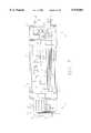
- FIG. 6is a perspective view of the open lower housing section of the present invention, showing the medical devices and system components contained therein;
- FIG. 7is a top plan view of the open lower housing section of FIG. 6;
- FIG. 8is an exploded view of the lower housing section
- FIG. 9is a block diagram of the communications, controls, and displays graphical interface
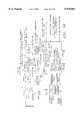
- FIG. 10is a schematic representation of the communication, controls, and displays hardware architecture
- FIG. 11is a block diagram of the communications, controls, and displays interface
- FIG. 12is a sample algorithm for the controls and displays
- FIG. 13is a symbol utilized to indicate that the defibrillator is off
- FIG. 14is a symbol utilized to indicate that the defibrillator is on and charging
- FIG. 15is a functional block diagram of the power management system
- FIG. 16is a block diagram showing the power management system in the autonomous mode
- FIG. 17is a block diagram showing the power management system in the recharge mode
- FIG. 18is a block diagram showing the power management system in the auxiliary power mode
- FIG. 19is a block diagram showing the power management system in the auxiliary power with recharge mode
- FIG. 20is a block diagram showing the power management system in further detail
- FIG. 21is a perspective view of the battery pack system
- FIG. 22is a schematic illustration of the battery segment
- FIG. 23is a full system schematic diagram of the environmental control system
- FIG. 24is a functional block diagram of the environmental control system
- FIG. 25is a block diagram of the environmental control system equipment cooling subsystem
- FIG. 26is a block diagram of the environmental control system patient cooling subsystem
- FIG. 27is a block diagram of the environmental control system pneumatic subsystem
- FIG. 28is a schematic representation of the heat load interactions
- FIG. 29is a. block diagram of the ventilator
- FIG. 30is a block diagram of the ventilator and onboard oxygen generator system
- FIG. 31is a block diagram of the communication system and external interfaces
- FIG. 32is a perspective view of a stretcher retention member
- FIG. 33is an electrical schematic of the present invention.
- FIG. 34is a flow diagram showing different display presentations
- FIG. 35is a functional diagram showing the software architecture of the present invention.
- FIG. 36is a sample screen display showing blood pressure
- FIG. 37is a sample display showing a plurality of controls
- FIG. 38is a sample screen display showing graphs of breathing rate and title volume
- FIG. 39is a sample screen display showing patient status
- FIG. 40is a sample screen display showing the results of performing the built in test (BIT), wherein passing a subsystem passing the built in test is represented a green line interconnecting the system BIT symbol and the subsystem symbol and a subsystem failing the test is represented by a red line interconnecting the system BIT symbol and the subsystem symbol;
- BITbuilt in test
- FIG. 41is a simplified block diagram illustrating operation of the control circuit.
- FIG. 42is a detailed block diagram illustrating the control circuit in further detail.
- FIGS. 1-42depict a presently preferred embodiment thereof.
- two self-contained transportable life support systems 10 of the present inventioncontain battlefield casualties,i.e., or medical patients 12, who have been readied for transport upon an evacuation vehicle, i.e., helicopter 14.
- a soldier 16views a hand held monitoring device 18 via which the medical condition of the medical patients 12 is monitored.
- the monitoring device 18provides an indication of the status of each patient 12 contained within a self-contained transportable life support system 10.
- the monitoring device 18prioritizes patients according to the severity of their medical condition, so as to provide an indication of which medical patients 12 should be evacuated first.
- the monitoring device 18performs a data logging function, so as to provide a record containing the identification of the medical patient 12, the medical condition thereof, the time of evacuation, and the destination to which the medical patient 12 is to be transported.
- Each of the medical patients 12has a plurality of medical devices in use thereupon, so as to enhance the survivability thereof.
- the medical devicesprovide medical monitoring and medical treatment which is intended to extend the golden hour sufficiently to allow transport thereof from the battlefield to a remotely located hospital.
- Integrated controls and displays 24minimize the effort required by a medic or other minimally trained personnel in order to provide adequate medical care for the patient.
- the self-contained transportable life support system of the present inventionis specifically configured to facilitate attachment of a standard NATO stretcher (Stanag) thereto via drop-in attachment wherein stretcher retention members receive and engage the handles of the standard NATO stretcher solely in response to placement of the stretcher thereupon.
- Stanagstandard NATO stretcher
- stretcher retention membersreceive and engage the handles of the standard NATO stretcher solely in response to placement of the stretcher thereupon.
- the medical patient 12is disposed upon a standard NATO stretcher 20.
- the stretcherattaches to the lower housing section 22 of the selfcontained transportable life support system via four stretcher retention members 24 which automatically attach the stretcher 20 thereto when the stretcher is placed upon the lower housing section 22.
- An optional upper housing section 26forms a canopy over the medical patient 12, and cooperates with the lower housing section 22 so as to define a housing which provides isolation for the medical patient 12.
- a transparent window 27is preferably provided to facilitate viewing of the medical patient 12.
- the upper housing section 26is optionally pressurizable so as to enhance such isolation.
- Positive pressurization, i.e., pressure above ambient, of the upper housing section 26is provided to isolate the medical patient 12 from care givers and/or the environment.
- Such positive pressurization of the upper housing section 26causes air to leak therefrom. Thus, air is prevented from leaking into the upper housing section 26.
- biological, chemical, and radiological isolationmay be provided for the medical patient 12 by filtering air prior to pressurizing the upper housing section 26 with it.
- the upper housing section 26may also be provided with a negative pressure, i.e., a pressure below ambient, such that air leaks from the environment into the container, so as to provide for isolation of the care givers from the medical patient. In this instance, air drawn into the upper housing section is filtered prior to being exhausted therefrom.
- a negative pressurei.e., a pressure below ambient
- the upper housing section 26is preferably formed of a lightweight, rigid, polymer or composite material. Alternatively, the upper housing section 26 may be comprised of a fabric, having support straps or hoops for maintaining the desired shape thereof. In any event, the upper housing section 26 is preferably configured so as to provide a substantially air tight seal to the lower housing section 22, so as to minimize air leakage either there into or therefrom, thus improving the isolation capability. However, it would be recognized that an absolutely air tight seal is not necessary since the upper housing section 26 can be pressurized as discussed above, so as to provide the desired isolation.
- the medical devicesare preferably integrated into the lower housing section 22 in a manner which minimizes the weight and volume thereof.
- Weightis minimized by eliminating components common to a plurality of the medical devices, such as the power supplies therefor.
- Volumeis minimized by such elimination of common components and also by packaging the medical devices more economically than is possible with off-the-shelf devices. Further, such integration of the medical devices provides for more efficient power consumption since the devices are powered from a common source and are under common control, so as to facilitate more efficient operation thereof.
- a fluid infuser 28which is stored within a storage compartment of the lower housing section 22 prior to use, may be laid upon the stretcher to provide fluid infusion for the medical patient 12.
- the stretcher 20comprises two poles 30, each pole having two handles 32, one handle being formed upon either end thereof.
- Canvas 34stretchers between the two poles 30.
- the lower housing section 22is configured to receive the feet 31 within channels 39 formed within the lower housing section 22, so as to prevent longitudinal movement of the stretcher 20 with respect to the lower housing section 22.
- the stretcher retention members 24prevent lateral, as well as vertical, movement of the stretcher 20 relative to the lower housing section 22.
- Either medical grade airi.e., oxygen enriched air 70 or oxygen 72
- oxygen enriched air 70 or oxygen 72is provided via the ventilator 50 to the patient 12.
- oxygen enriched air or oxygenmay be provided to the ventilator either via the onboard oxygen generator system, pressurized oxygen bottles, or via an external source thereof.
- the suction unit 44may be used to provide suction to maintain a clear airway or, alternatively, may be utilized to provide suction to wounds, as desired.
- Physiological monitors 74monitor such medical parameters as blood pressure, heart rate, ECG, etc.
- Defibrillator 76may be used when fibrillation is indicated by the physiological monitor 74 or by the defibrillator's automated assessment of patient status.
- a blood chemistry assessor 78provides blood chemistry assessment. Data logging facilitates review of the patient's monitored medical parameters and treatment.
- FIG. 3It is important to remember that the medical devices shown in FIG. 3 are actually integrated into the lower housing section 22 of the present invention, and are not off-the-shelf, separate discreet units, as shown.
- the medical devicesare illustrated as separate, discreet, off-the-shelf units for clarity only, and so as to give a general indication of the types of medical devices integrated into the present invention.
- the head end 26 of the lower housing section 22comprises a visual display 84 for displaying information regarding operation of the ventilator.
- Controls 86 for controlling operation of the ventilatorallow a care giver to vary the respiration rate and tidal volume.
- Physiological monitoringis facilitated via monitor 88 which facilitates display of blood pressure, temperature, ECG, etc. and also provides for the control of the medical monitoring devices which monitor blood pressure, temperature, ECG, etc.
- the controls of the physiological monitor 88also allow the care giver to preset alarm limits for physiological parameters such as blood pressure, temperature, ECG, etc. When such an alarm is exceeded, an audible alarm sounds.
- Intravenous drug administrationis facilitated via infusion pump 90, which may comprise a high volume infusion pump.
- infusion pump 90which may comprise a high volume infusion pump.
- three separate fluid inputsare accepted by the infusion pump 90 and three separate metered outputs are provided thereby.
- the three outputscan be joined together into a single output, in any combination desired.
- Suction reservoir 92facilitates the collection of fluids collected by one or more suction device(s).
- the lower housing section 22contains the medical monitoring devices and medical treatment devices necessary to prolong the golden hour sufficiently to enhance a patient's survivability during extended transport to a remote medical facility.
- the lower housing section 22preferably comprises a lightweight polymer or composite structure configured to contain the medical monitoring devices and medical treatment devices.
- the medical devicesare integrated with the lower housing section 22 in a manner which reduces the volume thereof. Such integration also facilitates construction of the present invention in a manner which allows it to be used in military vehicles having standard NATO stretcher mounts, wherein the size of equipment received within the standard NATO stretcher mounts is strictly constrained in order to avoid interference with nearby stretchers and/or other mounted objects, i.e., battlefield casualties on NATO stretchers.
- a monitor or touch screen display 25is formed at the head end 26 of the lower housing section 22.
- the touch screen display 26preferably comprises a closable cover 29 to provide protection thereto.
- a second monitor and/or touch screenmay be formed upon the inner surface of the cover 29, if desired.
- An environmental control system fan assembly 30is provided at the foot end 32 of the lower housing section 22 and comprises at least one fan for drawing air into the upper housing section 26 and filters for filtering the air.
- equipment fan assembly 34contains at least one fan for drawing air into the equipment compartment 36 of the lower housing section 22 and filters for filtering the air drawn into.
- the filters of the system fan assembly 34provide chemical, biological, and radiological filtering, so as to provide isolation of the medical patient 12 disposed within the upper housing section 26.
- the filters of the fan assembly 34provide particulate filtering, so as to inhibit contamination of the medical devices contained within the lower housing section 22.
- the air path of the upper housing section 26 and the lower housing section 22are separate and isolated from one another, such that the air in each path is not commingled.
- the equipment fansrun for a short period of time prior to the application of electrical power to the medical devices, such that any oxygen and/or hydrogen which is built up in the lower housing section 22 is exhausted prior to fully powering the system up, so as to mitigate any explosion or fire hazard which could be caused thereby.
- Power supply circuitry 36receives electrical power from battery packs 38 or power converters 44 to provide electrical power to the medical devices.
- the battery packs 38define first and second battery sections which cooperate to provide electrical power to the various medical devices of the self-contained transportable life support system.
- a controlleris configured to facilitate charging of one of the battery sections while the other of the battery sections is providing power to the self-contained transportable life support system, and then the roles of the two battery sections switch such that the second battery section provides electrical power to the self-contained transportable life support system while the first battery section is charging.
- a suction pump 40may be utilized to provide suction to maintain clearance of the airway, as well as to remove blood and/or other body fluids from wounds, etc. Fluids removed by the suction pump 40 may either be dumped overboard or deposited within suction bottle 42 for later analysis.
- Power converters 44convert electrical power from a building, transport vehicle, etc. into power which is usable for running the medical devices of the self-contained transportable life support system, as well as power for charging the batteries 38 thereof.
- Control circuitry 46facilitates control of the medical devices of the present invention such that the medical treatment devices thereof are responsive to the medical monitoring devices thereof and such that the medical treatment devices cooperate to provide beneficial medical treatment to the patient.
- the control circuitry 46is responsive to operator input via the touch screen display 26, a separate hand-held monitoring device, as well as remote control instructions from medical personnel at a remote medical facility.
- Ventilator pneumatic controller 48controls the ventilator compressor 50 so as to provide ventilation for the medical patient.
- the closed-loop ventilatoraccepts oxygen from either an external source or from the onboard oxygen generator/pressurized oxygen bottle/enrichment system.
- the ventilatorcan also be utilized to administer anesthesia.
- Oxygen generator 52provides oxygen or oxygen enriched air which may be provided to the patient through the ventilator.
- Channels 39are configured to receive the feet 31 of the stretcher 20, so as to prevent longitudinal and lateral movement of the stretcher relative to the lower housing section 22.
- Stretcher retention members 24facilitate drop-in attachment of the stretcher to the lower housing section 22 such that the handles 30 of the stretcher need merely be placed upon the stretcher retention members 24, which then open in response to the weight of the stretcher and automatically close about the handles thereof so as to provide secure attachment of the stretcher to the lower housing section 22.
- the stretcher retention members 24may be opened manually and then closed in response to lowering of the stretcher handles 30 thereupon.
- the stretcher retention members 24prevent lateral and vertical movement of the stretcher relative to the lower housing section 22.
- Oxygen reservoirs 56temporarily store oxygen generated by the oxygen generator 52.
- the use of an onboard oxygen generator 52eliminates the need to carry heavy and bulky bottled or liquid oxygen.
- the onboard oxygen generatorpreferably utilizes facilitative transport membrane to provide oxygen or oxygen enriched air to the medical patient.
- Heat exchangers 58facilitate temperature control of the patient by providing temperature controlled air or water thereto.
- An environmental control systempreferably comprises a vapor compression cooler and a heater and an air temperature controller.
- the air temperature controllercan both heat and cool air which is provided to the upper housing section 26 for breathing.
- the environmental control systemcomprises an air filter system for filtering breathing air supply to the upper housing section. The breathing air is filtered so as to remove biological, chemical, and radiological contamination in a manner similar to that of a contemporary gas mask.
- the lower housing section 22generally comprises a sled 100, padding 102 is disposed upon the sled 100 such that the patient is supported thereby when placed upon the lower housing section 22.
- the lower housing section 22is configured such that the canvas 34 of the stretcher 20 rests upon the pads 102, such that the pads 102 receive the full weight of the patient.
- the filter housing 104houses the fan and filter assemblies which provide cooling into the medical devices, as discussed above.
- Access door support stiffeners 106provide structural rigidity to the access doors.
- Forward access door 108provides access to the head compartment 11 of the lower housing section 22
- center access door 110provides access to the center compartment 13 of the lower housing section 22
- aft access door 112provides access to the foot compartment of the lower housing section 22.
- Center access door stiffenersattach to the center access door 113 to provide structural rigidity thereto.
- Environmental control system equipment exhaust housing 30contains the environmental control system fans and filters for providing filtered air to the upper housing section 26, as described above.
- the display 24is controlled via system management algorithms 202 which cooperate with low level digital and analog input/output channels 204.
- the low level digital and analog input/output channelscooperate with patient care management algorithms 206, the status of which are displayed upon display 24.
- Device communications and interfaces 208cooperate with patient care management algorithms 206 and system management algorithms 202.
- the display 25is preferably under the control of a CPU 302 having at least 8 megabytes of RAM 304 and at least 100 megabytes of hard disk or equivalent non-volatile storage 305.
- 48 channels of digital input/output 306are provided.
- the input/output channelsprovide information regarding device status, i.e., on/off, charge configuration, relay on/off, and digital sensors.
- the digital input/output 306also facilitates control of the defibrillator.
- Thirty-two channels of analog input/output 308provide pressure sensing, temperature sensing, velocity sensing, gas sensing, etc.
- Six serial input/output channelsprovide external communications, data storage device communications, physiological sensors, ventilator, and touch screen.
- control circuitry 46 of the central controllercontrols the operation of the onboard oxygen generator system 52, the ventilator controller 48, the environmental control system 49, the power distribution system 51, the suction unit 40, the display 25, the defibrillator 29, the infusion pump 28, the physiological monitor and IV pump controller 55, the patient sensors 57, and the communications unit 88.
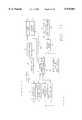
- FIG. 12a sample controls and displays algorithm is shown.
- the sample algorithmwhen a high CO 2 level is sensed, then stale air is dumped from the upper housing section 26 by starting the fan 154, if it is riot already running.
- the exhaust valveis opened, with a time delay, if desired. Air movement is preferably verified.
- Trend analysisis then initiated upon the patient to verify that CO 2 is being properly exhausted.
- the housing CO 2 levelis at an acceptable level, then the system returns to the normal operation state. If the CO 2 cannot be cleared, then an alarm is sounded to alert the care giver.
- FIG. 13shows the preferred symbol utilized to indicate that the defibrillator is off and FIG. 14 shows the preferred symbol used to indicate that the defibrillator is being charged. Flashing of the symbol of FIG. 14 indicates that the defibrillator is ready to discharge. Pressing the flashing symbol of FIG. 14 on the touch screen 25 causes the defibrillator to discharge.
- power converters 44are configured to accept electrical power from the Blackhawk Medevac helicopter 350, the HumVee 352, as well as STD CONUS POWER 354.
- Power conditioner 61assures that the power is compatible with the main bus 63 of the self-contained transportable life support system of the present invention.
- the batteries 38receive power from the main bus 63 to facilitate charging thereof and provide power to the main bus 63 when being utilized for the operation of the self-contained transportable life support system.
- Non-noise sensitive lodes 81receive power directly from the bus 63 while sensitive lodes 83 receive power via precision power supplies 85.
- the batteries 38provide electrical power to the environmental control system 49, the onboard oxygen generator system 52, the ventilator and compressor units 48, the suction unit. 40, the controls and displays unit 25, the communication unit 88, the defibrillator 29, the data storage device 55 (data storage device for maintaining a log of medical parameters and medical treatment provided), and the infusion pump 53.
- the power converters 44provide electrical power to the battery groups 38.
- electrical poweris provided by an outside source.
- Such electrical powermay comprise 400 hertz 500, 120 VAC 502 and/or 25 VDC 504.
- the power converter 44receives, the 400 hertz 500 and/or the 120 VAC 502 and provides an output at 21.2 amps maximum, 534 watts maximum to the ECS system 49, onboard oxygen generator system 52, ventilator and compressor unit 48, suction unit 40, control and display unit 25, communications unit 88, defibrillator 29, data storage device 55, and infusion pump 53.
- the battery power groups 38are charged while providing operation similar to that in the auxiliary power mode of FIG. 18.
- FIG. 20an overall schematic representation of the power management system is provided.
- This schematic representationshows the various relationships of the power sources, i.e., the 400 hertz 500, 120 VAC 502 and the 25 VDC 504.
- the battery power group 38may be charged, as shown in FIG. 19. Powers provided to the various loads as shown in FIGS. 16, 18 and 19.
- each battery sectionis preferably comprised of a plurality of battery packs 600, each battery pack comprising a plurality of individual batteries 602 which are connectable to the electrical system of the self-contained transportable life support system via negative bus bar support 604 and positive bus bar support 606.
- the negative bus bar support 604 and the positive bus bar support 606provide for both the electrical connection of the battery pack, as well as the mechanical mounting thereof.
- Negative relay control 608 and positive relay control 610facilitate selective reconfiguration of a particular battery pack from the remaining packs in the event of failure thereof protection diodes 612 isolate reconfigured battery cells and prevent overcharging of the battery 602.
- the battery pack containing that cellis automatically disconnected from the remaining battery packs, so as to facilitate the maintenance of desired power to the medical devices.
- Each battery packpreferably comprises 42 individual cells.
- a plurality of battery packssuch as those shown in FIG. 21 are configured so as to provide approximately 25.2 volts DC to the power bus.
- a nuclear/biological/chemical (NBC) filter 150 and a fan 152are disposed within the upper housing section fan assembly 30.
- the fan 152provides filtered air to cooling fan 154 which directs the filtered air onto the patient 12.
- a portion of the air brought into the upper housing section via blower 152is exhausted therefrom as leakage 156.
- Another portion of the air brought into the upper housing section 26 via blower 152is provided to the suction unit 40.
- Another portion 158, the remainder 160 of the air brought into the upper housing section via the blower 152is re-circulated within the upper housing section, preferably passing through air/water heat exchanger 162.
- the heat exchangerpreferably provides 1 gallon per minute of temperature controlled water at approximately 20 psid from the cooling unit 164.
- the cooling unit 164preferably comprises a motor driver 166 for driving a compressor pump unit 168 so as to circulate refrigerant through an evaporator 170 and a condenser 172 according to well-known refrigeration principles.
- a check valve 174prevent back flow of air into the suction unit.
- a check valve 176prevents back flow into the ventilator/compressor 50.
- the outputs of the ventilator/compressor 50 and suction unit 40may either be dumped overboard or dumped into a container, as desired.
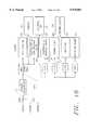
- a functional block diagram of the environmental control systemis provided. According to the preferred embodiment of the present invention, both a clean air path 400 and an open-loop cooling system 402 are provided. Ambient air 404 is NBC filtered 406.
- a pressurization unit 408pressurizes a patient compartment 410 of the upper housing section in a desired fashion.
- the patient compartment 410 of the upper housing sectionmay be pressurized to a level slightly above ambient to isolate the patient from the environment and care giver.
- the patient compartment 410 of the upper housing section 26may be pressurized to a level slightly less than ambient to isolate the care giver from the patient.
- Closed-loop cooling system 412facilitates desirable temperature control of the patient compartment 410.
- leakage overboard 414occurs.
- Exhalant dump 416is also exhausted from the patient compartment.
- the suction unit 40provides a dump 418 overboard.
- ambient air 404is subjected to particulate filtration 420.
- the particulate filtered airis then provided to the oxygen generating system 422, the medical electronics 424, the control electronics 426, and the mechanical/electrical equipment 428, all of which receive electrical power from the battery groups 430.
- the battery groups 430provide electrical power to the various air movers 432 which then exhaust hot air 434 out of the system.
- the hot exhaustreceives its heat from the closed-loop cooling system heat rejection unit 436.
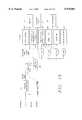
- the particulate filter 17provides particulate filtered air to the head compartment 11, center compartment 13, and foot compartment 15, in that order.
- sensor boards, precision power supplies, defibrillator board and battery, and the suction pumpare cooled by the particulate filtered air.
- the power converters 44, central controller 46, ventilator compressor 50, ventilator pneumatic controller 48, onboard oxygen generation system 52, compressor 51 as well as any other electrical devices disposed thereinare cooled by the particulate filtered air.
- the battery packs 78 and gear pumps 4are filtered by the particulate filtered air.
- the patient cooling subsystemcomprises a generally re-circulating air system wherein fan 154 provides the patient 12 within the patient compartment 410 defined by the upper housing section with temperature controlled air, preferably at 100 cubic ft. per minute at 0.20 inches water column.
- the airis provided to the patient at approximately 72° F. (22° C.). Approximately 379 watts of heat must be removed from the patient compartment 410 in order to maintain the exhaust temperature therein at approximately 84° F. (29° C.).
- the recirculating airis exhausted from the patient compartment 410 and provided to an air/water heat exchanger 162 which preferably circulates water at approximately 1 gallon per minute at 20 psid therefrom to the cooling unit 164.
- Waterpreferably exits the cooling unit 164 and enters the air/water heat exchanger 162 at a temperature approximately 65° F. and is pumped by two redundant gear pumps 180 and 182. After leaving the air/water heat exchanger 162, the water is at approximately 69° F. and is cooled by the evaporator 170 of the cooling unit 164 back to approximately 65° F.
- the onboard oxygen generator 52provides oxygen or oxygen enriched air 53, preferably at a rate of approximately 0.7 cubic ft. per minute average, 2.1 cubic ft. per minute peak, to the ventilator/compressor 50.
- Exhaust air 55 from the ventilator/compressorpasses to the patient 12 through check valve 176 and is preferably dumped overboard. Alternatively, the exhausted air may be filtered for later analysis.
- the NBC filter 150preferably provides 3.5 cubic ft. per minute max, 1.7 cubic ft. per minute average, and 1 cubic ft. per minute minimum, at approximately 1.2 inch water column minimum. Air from the NBC filter 150 and blower 152 provides air to both the ventilator/compressor 150 and the patient 12.
- the upper housing section 26receives heat load from the solar source (i.e., the sun), ambient air 502, the sky 504, and surrounding structures 506.
- the controlled environment 508receives heat loading from the solar source 500, the upper housing section 26, circulation fans and pressurization blowers 510, the insertion of powered objects 512, such as the IV and the data storage device, and the patient 12.
- onboard heat generators 518include the batteries, electronics, power converter, environmental control system hot side equipment, ventilator, and suction unit.
- the lower housing sectionis subject to heating and/or cooling via ground contact 520, the effects of surrounding structures 522, ground layer ambient air 524, and ground reflective solar radiation 526.
- the controlled environmentis also subject to pressurization air Leakage 514, and onboard air consumption 516.
- Ambient airis drawn through the NBC filter 150 by fan 152.
- Air compressor 700 driven by motor 702provides air through water separation filter 704 to air reservoir 706. Wall air is provided through connectors 710 to the regulator 712. The output of the regulator 712 is provided to the air reservoir 706.
- Ambient airis also provided to the onboard oxygen generator system 52, the output of which is low pressure oxygen or oxygen enriched air which is provided to optional buffer reservoir 714.
- oxygenflows through oxygen compressor 716 to oxygen reservoir 718 where it is stored at approximately 20 to 30 psi.
- Oxygenmay also be provided to the oxygen reservoir 718 from a wall outlet via connector 720 and regulator 722. Oxygen from the oxygen reservoir 718 is blended with air from the air reservoir 706 via blender 724 having a high pressure (20-30 psi) output. Ventilator controls 726 then facilitate the administration of oxygen or oxygen enriched air to the patient 12.
- Suctionis provided via suction tube 800 so as to facilitate air way clearance. Fluids drawn through suction tube 800 are collected in suction reservoir 802. Preferably, suction between 0 and 200 mmHg. is provided. Ventilation is facilitated via ventilation tube 804 which extends into the patient's trachea and is connected to pCO 2 capnograph sensor 808. Exhaust from the ventilation tube 804 is facilitated via expiration tube 806 from pCO 2 capnograph sensor 808. pCO 2 capnograph signal data is transmitted via capnograph electronics to the system control circuit.
- Optional vaporizing assembly 810facilitates the vaporization of anesthetic gases.
- the vaporization assembly 810can be by-passed, as desired.
- the ventilatorperforms gas mixing at a high pressure of between 20 and 50 psi. Air way pressure and tidal volume are controllable, either manually or via the system control circuit. Timing may also be either manually controlled or controlled via the system control circuit.
- the enclosure, upper housing section 21houses the patient 12.
- the physiological monitor and IV pump controller 55stores the output of sensors attached to the patient 12 and control pump 28.
- the local control module 762is a standalone device which may be carried by medical personnel to monitor the status of the patient contained within the self-contained transportable life support system of the present invention as shown in FIG. 1. Thus, a single local control module 762 can be utilized to monitor a plurality of different self-contained transportable life support systems to verify the proper operation thereof and the condition medical patient contained therein.
- the personal status monitor 18monitors the status of the patient and may control the infusion pumps 763 and also communicate with the physiological monitor.
- the pump 763may be a portable infusion external to the self-contained transportable life support system. Such communications preferably are facilitated via the radio 754 of the self-contained transportable life support system, or an equivalent external radio.
- the data storage device 90is in communication with a radio 750 so as to facilitate communications with remote medical personnel. Communications are optional and facilitated with administrative personnel to facilitate logistics regarding injured personnel at a ground station 752. Communications with external devices may be either via an RS-232 link, or preferably, an Ethernet link.
- a stretcher retention member 34according to the present invention is shown.
- the structure retention memberis preferably configured such that attachment of the lower housing section to a stretcher is facilitated by merely dropping or lowering the stretcher upon the stretcher retention members 54 such that the handles 32 of the stretcher 20 contact the stretcher retention members 541 and are captured thereby.
- the stretcher member 34may be configured such that manual opening thereof is required prior to placing the stretcher 20 thereupon. Once the stretcher 20 is then placed the stretcher retention member 34, the stretcher retention member 34 closes and locks about the handles 32 of the stretcher 20.
- a lower coupling 122is formed upon a base 120.
- the base 120facilitates attachment of the stretcher retention member 34 to the lower housing section 22 of the present invention.
- An upper coupling 124is pivotally attached to the lower coupling 122 and is disposable in open and close positions. In the open position, as shown in FIG. 32, an activation bar 126 extends approximately perpendicularly from the upper coupling 124 such that when a stretcher 20 is laid upon the lower housing section 22, one handle 32 thereof engages the activation bar 126 and pushes the activation bar downwardly, thus rotating the upper coupling 124 into the closed position thereof.
- the upper coupling 124locks in place, such that it must be manually unlocked in order to remove the stretcher 20 from the lower housing section 22.
- a schematic of the present inventionis provided.
- a variety of different power inputsmay be utilized to operate the medical devices thereof and/or simultaneously charge the batteries thereof.
- such external powermay comprise 115/200 VAC, 400 Hz; 120 VAC, 60 Hz; 25 VDC.
- This poweris provided to power converters 44 which provide nominal 25.2 volts DC to facilitate operation of the medical devices and/or charging of the batteries 38.
- Control circuit 46facilitates cooperation of the different medical monitoring and medical treatment devices, so as to provide proper medical care for the patient, depending upon the particular medical problems thereof.
- the touch screen monitor 24displays various medical parameters 790, 791, 792, 793 and 794, as well as displaying controls 795 for facilitating desired operation of the medical devices.
- the medical monitoring devices and medical treatment devices of the present inventionare preferably under the control of a control circuit 46, preferably a general purpose microprocessor, which runs an algorithm program to facilitate desired monitoring and control of the medical devices.
- a control circuit 46preferably a general purpose microprocessor, which runs an algorithm program to facilitate desired monitoring and control of the medical devices.
- the software architecturecomprises system input/output 900, communication 902 and a graphical user interface 904.
- system management functions 906, as well as patient care functions 908comprise applications which run under any suitable operating system.
- the system input/outputincludes device input/output, data storage device, ventilator, touch screen, defibrillator, radio frequency communications, infusion pump and physiological sensors.
- the screen input/output for the environmental control system, power, gas monitoring, contaminants, defibrillator, and equipment bayis also provided.
- System input/outputalso includes power management, environmental control system management, i.e., patient compartment, as well as the equipment bay. Preferably, built-in test functions are provided.
- the graphical user interfaceincludes ventilator management, onboard oxygen generator system management, defibrillator management, suction unit control, patient temperature management, and sensor monitoring.
- the graphical user interfacealso facilitates a medic interface, physician interface, alarm notification, system diagnostics, and system maintenance.
- a sample display of a screen for indicating blood pressureis provided.
- Systolic blood pressureis indicated by the upper most curve 940 and diastolic blood pressure is indicated by the lower most curve 942.
- a sample display indicating the status of the medical devicesi.e., defibrillator and ventilator, as well as patient medical parameters is provided. Since a touch screen monitor is utilized, the medical devices of the self-contained transportable life support system of the present invention can be both monitored and controlled from the touch screen monitor 25. For example, a defibrillator can be turned off, activated so as to initiate charging, and caused to discharge by pressing the heart shaped symbol 750.
- a sample screen further illustrating medical device status and patient medical parametersis provided.
- Control of the medical devicesis provided via a touch screen interface. For example, by pressing the up arrow 950 associated with breathing rate, the breathing rate provided by the ventilator can be increased. Likewise, oxygen concentration and tidal volume can easily be varied, as desired.
- FIG. 39a sample screen showing patient status is provided. As shown, the heart rate 960 is 80 beats per minute, the blood pressure 926 is 120/80, and the patient's temperature 964 is 98° F.
- the sample screenshows that the defibrillator is off and suction is on and that the ventilator is providing ventilation at a rate of 20 breaths per minute with a tidal volume of 780 ccs. and oxygen saturation of 97%.
- the symbol in the center 980is representative of the system built-in-test (BIT). From the system BIT 980 symbol extends lines to a ventilator symbol 981, and ECS symbol 982, a suction unit symbol 983, an onboard oxygen generator system symbol 984, a defibrillator symbol 985, a communications unit symbol 986, a display symbol 987, and a power symbol 988.
- BITsystem built-in-test
- the line from the system BIT symbol 980 to that subsystem and the subsystem symbolwill be green in color.
- a subsystem failureis indicated by displaying a green line from the system built-in-test symbol 980 to the appropriate subsystem and the subsystem symbol will be red in color.
- a failure of the communications channel from the system to the subsystemwill be indicated by displaying a red line from the system built-in-test symbol 980 to that subsystem symbol and the subsystem symbol will be red in color because its status cannot be verified.
- the line joining the system built-in-test symbol 980 to the communications unit symbol 986would be green and the communications unit symbol would be red instead of green.
- the communications channel to the ventilator 981failed the system built-in-test, then the line joining the system built-in-test symbol 980 to the ventilator symbol 981 would be red instead of green and the ventilator symbol 981 would be red instead of green because its status cannot be verified.
- the self-contained transportable life support systemincorporates a control circuit that functions to monitor, control, prioritize and regulate power to the functional devices and circuits of the life support system.
- a control circuitthat functions to monitor, control, prioritize and regulate power to the functional devices and circuits of the life support system.
- the particular manner in which the control circuit performs those functionsmay be varied substantially without departing from the broader aspects of the present invention. Implementation of the control circuit functions will vary in accordance with the operating characteristics of the particular devices and other circuits cooperating with the control circuit, as well as the desired level of sophistication to be implemented.
- the control circuitfunctions via a single redundant data bus to communicate information to and from the functional devices and circuits via one or more electrical busses, to which the medical devices and other circuits are operatively connected.
- information to and from the control circuitmay be formatted in digital packets whereby each functional device and circuit may be separately addressed to communicate control and data signals.
- control circuitmay be implemented in a construction whereby the control circuit is separately connected to the other functional devices and circuits via substantially dedicated circuit paths. In either case, the control circuit provides adaptive control of the functional devices and circuits in order to maintain desired life support conditions of the patient.
- control circuitmay be placed in an automatic mode whereby monitoring and treatment functions can be selectively implemented, modified, sequenced and terminated by the control circuit, without need for operator intervention.
- the control circuitis also operable in a manual, or partially manual mode, whereby some or all of the functions of the control circuit may be manually regulated by an operator, overriding control circuit programming.
- the control circuitmay function to facilitate manual operation of only select functions of a medical monitoring device, medical treatment device or environmental control device.
- such manual operationmay be effected by medical personnel at a remote station, in radio communication with the life support system, whereby the patient life support conditions and environmental conditions within the housing may be remotely monitored and regulated.
- FIG. 41is a simplified block diagram illustrating operation of the control circuit to provide adaptive control of the interconnected functional devices and circuits.
- control circuit 46is in bi-directional communication with the medical device 803, which includes medical monitoring devices 805 and medical treatment devices 807, the control circuit is thereby operative to receive information from the medical monitoring devices 805, and to regulate operation of medical treatment devices 807, in response to that information.
- a medical monitoring devicemay be implemented as an electrocardiograph and the medical treatment devices 807 may be implemented as defibrillator.
- information from the medical monitoring devices 805may thereby provide information respecting cardiac condition of the patient.
- the control circuitis operative to implement programming to activate the medical treatment device, as necessary to bring the monitored life support condition to acceptable parameters.
- the control circuit 46is operative to provide adaptive control of the medical treatment devices, based upon not simply one condition in isolation, but rather upon an evaluation of multiple life support conditions, and the inter-relationship thereof. As a result of such evaluation, the control circuit 46 may regulate the operation of the medical monitoring devices 805, the medical treatment devices 807 and the environmental control devices 809.
- the control circuit 46can monitor, implement, modify, sequence and/or terminate the monitoring functions of medical devices 805, and/or the treatment functions of one or more medical treatment devices 807, in response to adaptive program control.
- Environmental control devices 809may be implemented as monitoring devices and/or regulating devices operative to sense and/or regulate environmental conditions within the housing. Such conditions may include temperature, sound, light, pressure, humidity patient inclination and other environmental conditions. Thus, for example, environmental control devices 809 may be operative to sense chemical or bacterial conditions within the housing, and to implement air filtration functions to deplete any chemical, biological, or radiological contaminants. In the presently preferred embodiment, such air filtration functions are normally implemented on a continuous basis in order to assure that the environmental conditions within the housing remain isolated from environmental conditions external to the housing.
- Input device 811 and audio/video device 813are preferably connected to an exterior surface of the housing to allow access to the control circuit without the need to sacrifice environmental isolation of the patient within the housing.
- Input device 811is operative to input instructions or requests for information to control circuit 46.
- the control circuit 46is operative to regulate the operation of the functional devices and circuits in accordance with proper control.
- Audio/video device 813permits an operator to view information communicated to the control circuit 46, and monitor the operation thereof.
- the audio/video device 813allows for audio communication with the patient within the chamber, and/or an operator located at a remote station 815.
- the remote station 815may be located at a hospital or other medical service facility where trained medical personnel may monitor and regulate the operation of the life support system, via a radio frequency link to communication circuit 817.
- the communication circuit 817is provided with a transmit circuit 819 and a receive circuit 821. Transmit circuit 819 and receive circuit 821 are collectively operative to communicate information and instructions between remote station 815 and the control circuit 46.
- Remote control signals communicated from remote station 815may be interpreted by control circuit 46 to regulate the operation of medical monitoring devices 805, medical treatment devices 807 and/or environmental control devices 809.
- a microphone and speaker disposed within the housingfacilitates audio communication between the patient and/or local care giver and an operator remote station 815. The patient may thereby verbally communicate his condition and treatment request to the remote station 815, which may in turn access patient life support condition information from medical monitoring devices 805, via control circuit 46.
- the operator at remote station 815may further regulate the medical monitoring devices 805 to obtain further information as may be considered useful by the operator. Upon evaluation of such information, the operator at remote station 815 may thereupon direct the control circuit 46 to regulate the operation of medical treatment devices 807 in accordance with a desired treatment plan.
- the effectiveness of that plancan be constantly monitored by accessing information from the medical monitoring devices 805 and by direct verbal communication with the patient via a microphone and speaker or monitor disposed within the housing.
- the life support systemmay further be provided with a reader 823 operative to read information disposed on a medical storage device 825, and to communicate such information to control circuit 46.
- Reader 823may, for example, operate to input information concerning a patient's medical history to the control circuit 46.
- the control circuit 46is thereupon operative to regulate operation of the medical monitoring devices 805, medical treatment devices 807 and environmental control devices 809, in response to such information.
- control circuit 46is preferably also operative to simulate a plurality of life support conditions to an operator, to monitor an operator's utilization of the medical devices in response to such simulated life support conditions, and to evaluate the effectiveness of the operator's utilization of the medical devices.
- the control circuit 46thereby may operate in a training or simulation mode without any patient present within the housing.
- the control circuit 46may also function as a power regulator to regulate the application and distribution of electrical power to the medical devices.
- the control circuit 46further comprises power regulating circuit 827, charging circuit 829 and first and second battery sections 831, 833.
- the power regulating circuit 827operates to regulate the operation of charging circuit 829 to alternately charge one of first battery section 831 and second battery section 833, while power is drawn from the other battery section. External power provided to charging circuit 829 may thereby be directed to charge first battery section 831, while second battery section 833 provides output power to medical devices 803 and other functional components of the life support system.
- power regulation circuit 827may thereupon regulate the operation of charging circuit 829 such that external power is applied to charge second battery section 833, while power from first battery section 831 is applied to medical devices 803.
- the control circuit 46may further be operative to regulate the distribution of power from the first and second battery sections 831, 833, in accordance with a preset priority status assigned to the medical devices, environmental control devices and other circuits within the life support system.
- the power regulation circuit 837is operative to monitor the available power from the first and second battery sections 831, 833.
- the control circuit 46is operative to monitor the power requirements of the medical devices, environmental control devices and other circuits within the life support system, and to distribute available power to those devices and circuits in accordance with an assigned priority status attributable to those devices and circuits.
- control circuit 46is further operative to modify the assigned priority status of individual medical devices, environmental control devices and other circuits within the life support system, in response to monitored conditions of the life support system, or in response to manual control.
- control circuit 46regulates power distribution to the individual medical devices, environmental control devices and other circuits in accordance with urgent medical conditions as may arise within the life support system.
- control circuit 46may be modified, simplified or enhanced, in accordance with a particular application, without departing from the broader aspects of the present invention.
- the transportable life support system of the present inventionprovides individual, personalized, medical intensive care for military casualties, medical patients, chemical/biologically contaminated patients requiring isolation, and any other personnel who require rapid transport to a medical care facility or sustained ICU care in any care setting.
- the transportable life support system of the present inventionprovides means for quickly and easily re-configuring austere facilities into resuscitative, operative, and post-operative medical care facilities.
- various non-medical field environmentssuch as those of a ship, aircraft, school, office, home, clinic, etc. may be quickly transformed into an intensive care environment with the use of the transportable life support system of the present invention.
- the transportable life support systemprovides the medical monitoring and care devices required for such intensive care applications.
- the transportable life support system of the present inventioncan be utilized as a sterile environment for surgical procedures if necessary.
- the transportable life support system of the present inventioncomprises medical equipment commonly utilized in intensive care situations, which is specifically configured as a lower housing section which can be hand carried by two people and is configured to mount to standard military evacuation vehicles and can be adapted to mount to civilian emergency medical care vehicles or for use in a hospital.
- the transportable life support system of the present inventionminimizes the number of care givers required during resuscitation and transport and also minimizes the amount of skill required to be possessed by such care givers.
- intelligenceis provided in the transportable life support system so as to facilitate standalone operations utilizing closed-loop controls.
- On-board sensorsprovide inputs for physiological parameter processing which supports intelligent decision making for operation of the various incorporated intensive care medical devices.
- the physiological parameter processingalso facilitates treatment administration by providing instructions to trained or untrained personnel regarding the patient's medical needs. Both patient and life support system status reporting and management is also facilitated.
- a remote care givermonitors the on-board sensors and provides instructions to the transportable life support system, so as to provide enhanced care for the medical patient.
- Telecommunications capabilitysupports such remote reporting, query, and command/control operations.
- the transportable life support system of the present inventionprovides an integrated medical device or intensive care unit (ICU) having standalone capability.
- ICUintensive care unit
- the transportable life support systemmay be configured to operate in a standalone, local, interfaced, or remote mode of operation.
- the standalone mode of operationprovides the most sophisticated autonomous control of the medical devices utilizing sensor inputs from the medical patient.
- the interface mode of operationallows for electrical, oxygen, and data interface to the transportable life support systems operating environment, e.g., an evacuation vehicle, auxiliary support system, etc., so as to minimize taxing of the transportable life support systems' own resources, thereby enhancing their lifetime.
- data communicationis provided to a remote site, typically a medical professional, who monitors and evaluates data from the transportable life support system and provides trauma treatment inputs to the life support medical devices.
- the present inventioncan easily be integrated into various battlefield, civilian emergency logistics, and resource allocation systems.
- information regarding battlefield casualties and their medical conditionscan be readily compiled and evaluated at a central location.
- Such logistic considerationsmay also be useful in civilian applications particularly during catastrophes such as earthquakes, floods, hurricanes, etc.
- the medical equipment of the transportable life support system of the present inventionhas been configured to fit within a lower housing section having a height of approximately 6 inches.
- Such configurationis compatible with standard NATO litter mounts such that transportable life support system of the present invention may simply be carried aboard such military evacuation vehicles in the same manner that a standard NATO structure having a battlefield casualty disposed thereupon is carried.
- the transportable life support system of the present inventionis specifically configured so as to facilitate transport upon standard military evacuation vehicles.
- the physical envelope of the transportable life support systemis constrained to 20 inches of height, 22.75 inches of width, and 85.5 inches of length.
- the lower housing section upon which the medical patient is placed and within which the medical devices resideis constrained to a height of 6 inches.
- Such constructionassures that the transportable life support system of the present invention attaches such standard military vehicles via the stretcher handles of the standard NATO stretcher to which the transportable life support system is attached. All of the controls and monitoring devices of the present invention are fully operable during transport of the medical patient.
- the environmental control systemalso facilitates patient comfort management, by maintaining a comfortable temperature.
- the lower housing sectionprovides a physical bed upon which the stretcher and medical patient are placed and also facilitates tie-down thereof, so as to avoid upset during transportation.
- the environmental container(chamber) provides isolation from adverse chemical/biological environments and also facilitates reverse isolation that may be necessary when the medical patient is contaminated with a chemical or biological agent.
- the transportable life support system of the present inventionis fully autonomous, utilizing standalone utility capabilities such as internal power, environmental control onboard oxygen generation enhancement, and autonomous communications.
- the communications capability of the present inventionincludes reporting of the status of the patient, as well as the transportable life support system itself. Both local and remotely communicated alarms provide an alert that medical or system parameters have exceeded desirable limits. Recorded information regarding the status of the patient is maintained on board the transportable life support system and may be communicated to another site. The communication of this information is particularly useful when advance preparation is necessary to assure adequate medical treatment for the medical patient. For example, medical personnel may be alerted in advance to the medical patient's arrival and the particular problems and needs of the medical patient such that the appropriate equipment and personnel are on-hand upon the medical patient's arrival. In addition, recording of treatment data, patient data and system data is valuable in medical research.
- the communication systemincludes location sensing and communicating equipment for providing the location of the transportable life support system to a remote location. It is preferably implemented utilizing the Global Positioning System (GPS). Additionally, the maintenance requirements for the transportable life support system are preferably automated and integrated into the system such that notification of a particular requirement is provided upon the display thereof, as well as instructions for performing such maintenance, if desired. Onboard repair advice and maintenance procedures may optionally also be provided.
- GPSGlobal Positioning System
- Local mentoringis provided so as to minimize the training and skill required in order to properly prepare a medical patient for transport, i.e., stabilize the medical patient.
- Such local mentoringis provided via either autonomous operation of the life support system utilizing onboard sensors and diagnostic software, or, alternatively, via remote teleconsulting utilizing the onboard telecommunications capability.
- a training modeis available which allows a user to simulate various different types of trauma casualties, and thus allows care givers to attain proficiency in the proper use of the transportable life support system of the present invention.
- the use of the transportable life support system of the present inventionfacilitates mobile, agile, war fighting, since the requirement for treating battlefield casualties within the theater of operations is substantially mitigated thereby.
- battlefield casualtiesare immediately transported to a remote hospital, evacuation of such casualties and replacement thereof with new personnel, e.g., soldiers, is readily facilitated.
- new personnele.g., soldiers
- the availability of adequate medical supportsubstantially influences a soldier's willingness to engage the enemy.
- the present inventionnot only enhances the medical treatment of such battlefield casualties and logistics associated with evacuating and replacing such casualties, but also enhances the soldier's ability to fight.
- the present inventionis capable of providing trauma care within minutes. Because of its lightweight and compact structure, it may readily be deployed to the battlefield front civilian disaster areas where casualties commonly occur or pre-positioned in potential disaster areas. Also, because of its rugged, integrated structure, the present invention may be air-dropped to remote, inaccessible locations and is also configured for air retrieval. Such configuration additionally makes the present invention desirable for use in rescue activities in a remote and inaccessible location, such as a steep, rugged terrain, shipboard and small watercraft, and arctic conditions. The present invention may find particular applicability in cold weather environments, wherein the ability of the environmental chamber to isolate the medical patient from such cold is beneficial.
- location of battlefield casualtiesfurther facilitates practical command decision making regarding real-time modifications to battle plans. For example, an excessive number of battlefield casualties originating from a common battlefront location would tend to be indicative of the need for reinforcements at that location.
- the transportable life support system of the present inventionis preferably configured to accept computerized medical records, such as those which are anticipated to be carried by individual soldiers. As those skilled in the art will appreciate, attempts are presently being undertaken to incorporate military medical records into dog tags, ID cards, etc. so as to facilitate the automatic retrieval of such data. Thus, the medical history of an individual soldier is quickly transferred to the control system of the transportable life support system such that pertinent information contained therein may be utilized for the diagnosis and treatment of the battlefield casualty.
- the environmental chamber of the present inventionmay be utilized in controlled pressure or hyperbaric applications, so as to provide desired medical treatment for the battlefield casualty.
- desired medical treatmentfor the battlefield casualty.
- a pressurization suitmay be utilized to control blood flow to portions of a battlefield casualty's body, so as to reduce the likelihood and/or severity of shock and also so as to mitigate bleeding therefrom.
- repressurizable pantsmay be utilized to limit blood flow to the lower extremities, so as to mitigate bleeding therefrom and also so as to mitigate the undesirable effects of shock.
- Trainingis facilitated by specifically accommodating well-known training dummies, such as ResusiAnnie (which is commonly used to train for cardiopulmonary resuscitation), and Harvey, a well-known cardiovascular resuscitation dummy.
- ResusiAnniewhich is commonly used to train for cardiopulmonary resuscitation
- Harveya well-known cardiovascular resuscitation dummy.
- a human subjectis placed within the transportable life support system of the present invention and a desired physical problem is specified, via a care giver input.
- the systemthen simulates sensor inputs from the patient and instructs the care giver to take specific action.
- a training dummyis utilized in place of a human being.
- the transportable life support system of the present inventionis utilized in a standalone mode, i.e., wherein no personnel or dummy is utilized to simulate a battlefield or civilian casualty. A type of injury is specified or randomly selected by the training system and the care giver is instructed as to how to provide care therefor.
- a cardiac assistmay be provided.
- the cardiac assistcomprises either a mechanical chest compression device, an intra-aorta balloon pump, or an extracorporeal pump.
- An extracorporeal pump, oxygenator, and warmer/coolermay be provided so as to facilitate cardiac assist, blood oxygenation, and control of body core temperature.
- the extracorporeal chillermay be utilized to induce hypothermia, so as to decrease mortality by mitigating the undesirable effects of shock, decreasing blood flow, and consequent bleeding, and decreasing the body's requirement for oxygen.
- the transportable life support system of the present inventionalso provides a portable operating lower housing section which may be utilized in various different non-sterile environments for the performance of emergency medical operative procedures.
- the upper housing section 26 and filter systemprovides isolation from external contaminants/contagions.
- Optional isolation glovesprovide access to the battlefield casualty while maintaining a sterile environment therefor.
- Configuring the environmental chamber for hyperbaric applicationsalso facilitates its use in the treatment of various typical conditions wherein increased oxygen delivery is indicated. Use as a hyperbaric chamber is also preferably facilitated.
- the medical devicesare integrated with the transportable lower housing section so as to provide modular construction.
- Such modular constructionfacilitates easy removal and replacement of each medical device, so as to facilitate maintenance thereof.
- Such modularityalso facilitates the configuration of a transportable life support system which is specifically configured for a particular application. For applications wherein a particular type of medical condition is anticipated, only those medical devices required for the treatment of that medical condition are included. This reduces the weight of the transportable life support system, as well as the cost associated therewith. For example, if the present invention were to be utilized at a non-contact sporting event, such as a marathon, then those medical devices for monitoring and supporting cardiac function would be necessary since heart attacks are common during such events. However, those medical devices commonly associated with the treatment of trauma, such as the ventilator, may not be required.
- Such modular constructionalso facilitates quick reconfiguration of the transportable life support system for use in various different applications. Since such modular construction allows for the quick removal and/or replacement of the various medical devices thereof, a transportable life support system can be sent to a central location wherein a variety of such medical devices are stored and can there be quickly reconfigured for a particular use, as desired.
- Medical treatment devices of the present inventionare responsive to the medical monitoring devices thereof. However, such interactions are based upon the particular medical condition of the medical patient being treated thereby. Thus, rather than a particular medical treatment device being solely responsive to a particular medical monitoring device, each medical treatment device is responsive to those particular medical monitoring devices which are indicative of the medical patient's condition. Thus, according to the preferred embodiment of the present invention, a computer monitors the status of all of the medical monitoring devices and then, based upon a control algorithm, actuates those medical treatment devices which are necessary for the proper treatment of the medical patient. As such, the various complex interactions of the medical monitoring devices and medical treatment devices are possible.
- the prioritization schedule utilized to shut down the various systems and/or medical devices of the present invention as battery power diminishesis preferably a dynamic schedule based upon the particular condition of the medical patient.
- those medical devices which are most necessary for the proper medical care of the medical patientremain activated the longest. For example, for a medical patient having trouble breathing, the ventilator would be given highest priority and would be the last medical device to be deactivated. In this manner, the time required to transport the medical patient to a hospital is extended and the medical patient's probability of surviving such transport are enhanced.
- an estimated time to reach the destinationis entered. Based upon the estimated time of transport and the medical patient's medical condition, a prioritization schedule is generated which assures that those medical devices required for the proper medical treatment of the medical patient remain energized for the duration of the transport. Thus, as the medical patient requires ventilation and the estimated time of transport is two hours, then power is; managed in a manner which assures that the ventilator remains activated for two hours.
- the paddingcushions the medical patient.
- the stretchermay be positioned lower, i.e., closer to the lower housing section, thereby reducing the overall height of the life support system.
- the medical patientdoes not rely upon the stretcher to provide a comfortable and resilient surface upon which to lie, but rather is cushioned by the padding of the lower housing section itself.
- the handlesmay optionally be deployable from a stowed position, such that they are out of the way when not being utilized.
- paddingalso facilitates the transport of a medical patient upon the lower housing section without the use of a stretcher.
- the medical patientlies directly upon the padding of the transportable lower housing section.
- handlesare formed directly to the lower housing section to facilitate carrying thereof without an attached stretcher.
- the padding formed upon the lower housing sectiondefines a bed for the medical patient.
- Tie downs, belts, and/or bucklesare optionally provided so as to secure the medical patient to the lower housing section, to prevent undesirable movement thereof during transport and/or treatment.
- the transportable life support system of the present inventionis preferably configured to be airworthy. Thus the transportable life support system does not radiate excessive levels of electromagnetic radiation. Further, the transportable life support system is configured so as not to be substantially susceptible to environmental electro-magnetic radiation, such as that generated by an aircraft or vehicle.
- the transportable life support systemis configured so as to be compatible with utilities commonly found upon military vehicles and in medical environments such as power, oxygen, etc.
- brushless exhaust fanscommence operation before power is applied to any other electrical circuit of the present invention.
- the exhaust fanspurge air from within the lower housing section, thereby likewise purging any oxygen which potentially leaks from the oxygen reservoir and/or lines and/or pressurized oxygen bottles, as well as any hydrogen which may potentially leak from batteries.
- actuating the brushless exhaust fansfirst mitigates any explosion or fire hazard associated with the presence of such gases within the lower housing section.
- the equipment and patient air pathsare completely separate from one another.
- the air path of the equipment bay within the lower housing sectionis such that air is drawn over the equipment contained therein, from one end of the lower housing section to the other end thereof.
- the air within the upper housing section 26, as well as the air provided to the ventilatoris pre-filtered through a nuclear, biological, and chemical (NBC) personal filter, such as those commonly used in military gas masks.
- NBCnuclear, biological, and chemical
- a hot air blanketmay be utilized to distribute hot air to a medical patient through a porous side thereof.
- hot air flowis primarily directed from the blanket to the medical patient.
- a pair of hot air blanketsmay be utilized such that the medical patient lies upon one and is covered by another.
- the hot airmay be collected under the upper housing section and then recirculated, so as to further enhance rewarming.
- a water blanketmay be utilized to distribute hot water to a bladder-type blanket.
- a water blanketmay be utilized both under and on top of the medical patient. The water is recirculated and reheated, as necessary.
- Dry blanketsmay utilize either the medical patient's own body heat or an electrical or chemical heating pad. Again, dry blankets may be placed both beneath and on top of the medical patient. Either the hot air blanket, water blanket, or dry blanket may be formed in a modular fashion so as to facilitate localized heating of the medical patient as desired.
- Upper housing section heatingcan be utilized to warm the air within the upper housing section in order to facilitate rewarming.
- Rewarming of the medical patientis preferably performed with the upper housing section 26 in place, so as to provide protection from environmental elements.
- Body heatingmay additionally be accomplished via extra-corporeal warming of the medical patient's blood.
- Rewarming of the medical patientmay occur either gradually or at a maximum rate. Gradual rewarming is preferably performed at approximately 1° F. per hour.
- the standard approach for rewarming a hypothermic medical patientis total body immersion in a fluid bath, generally not exceeding 110° F.
- the objectiveis to rewarm the medical patient's body as rapidly as possible, but also to limit the temperature applied to the skin to less than 110° F. in order to avoid skin and/or tissue damage.
- Such fast rewarmingmay be indicated by severely depressed cardiac function or circulation. It is generally necessary to bring the core temperature to above 90° F. before adequate cardiac contractility can be resumed in order to facilitate sustained circulation. Defibrillation may also be necessary to restore cardiac rhythm if fibrillation occurs after the cold arrest.
- the defibrillator of the present inventionis preferably configured so as to be inoperative when the medical patient is under hypothermic conditions, since use thereof would not be beneficial to a hypothermic medical patient.
- the hot air blanketpreferably comprises a Bair-Hugger type of blanket.
- a Bair-Hugger type of blanketWhen hot air is blown through a blanket having an aluminized plastic layer on one side thereof and a very porous material on the other side thereof so as to facilitate desired hot air distribution. In this manner hot air can be provided to a hypothermic medical patient over a very large area thereof.
- Clinical reportsclaim the hot air blanket to be as effective as water blanket for the rewarming of hypothermic medical patient using only top-side coverage thereof.
- the padding formed upon the lower housing sectionis either porous or has air channels formed therethrough so as to facilitate hot air distribution over the lower surface of the medical patient.
- the lower housing section 22preferably exhausts approximately 100° F. air at approximately 50 ft 3 per minute in order to dissipate approximately 933 watts of thermal heat flow therefrom.
- the temperature of the exhausted airmay reach a maximum of approximately 161° F. if the inlet air is at a temperature of approximately 95° F.
- Inlet air for the equipment bayis filtered for particulates, but is not nuclear/biological/chemical (NBC) filtered.
- Exhaust air from the equipment baymay be utilized for air blanket rewarming of a hypothermic medical patient. If equipment bay exhaust air is utilized for rewarming of a hypothermic medical patient, then it is recommended that the upper housing section be removed or substantially opened, so as to limit undesirable breathing of the equipment bay exhaust air.
- the equipment bay airafter being warmed by the equipment bay, is NBC filtered before being applied to the hot air blanket.
- the upper housing sectionmay remain in place and fully closed, so as to provide desirable NBC protection.
- a water blanketmay optionally be provided above and/or below the patient in order to facilitate hypothermic rewarming.
- a recirculating water/anti-freeze mediumis utilized to facilitate heat transfer from a STEPO micro-cooling system to heat exchanges which cool the air being circulated in the patient compartment.
- a heating and cooling circuitcan be provided so as to facilitate direction of the water path into a circulating water blanket which is then applied to the patient.
- a heaterwould then heat the water/anti-freeze mixture, if desired, prior to mixture flowing into the water blanket.
- a second such blanketmay be provided beneath the medical patient, so as to enhance heat transfer.
- the padding formed upon the upper surface of the lower housing sectionoptionally comprises heating or temperature controlled pads.
- heating or temperature controlled padsPreferably, either circulating water or electrical heating elements are utilized to control the temperature of the pads.
- temperature controlmay be provided via heating with a dry blanket, which itself is preferably either electrically or chemically heated, and which has a wet towel in laminar juxtaposition thereto.
- the wet towelfunctions to increase thermal conduction between the dry blanket and the medical patient and also facilitates more even distribution of the heat from the dry blanket.
- heating modulesare utilized to provide for the selective heating of local areas, typically the more densely vascularized regions of the neck, arm pits, groin, behind the knees, etc. At these locations, blood veins are disposed close to the body's surface, thereby facilitating heat transfer to the medical patient without requiring extensive heating of the surrounding tissue. Such undesirably excessive heating increases oxygen demand before the ventilation and circulation supporting medical devices can accommodate such increased demand. Additionally, the use of such modules to facilitate localized heating allow the localized heating to continue while other treatments are performed which require better access to the medical patient than is possible with continuous blanket coverage. That is, while a blanket would have to be removed in order to facilitate the performance of such treatments, thereby at least temporarily terminating heat control of the medical patient, such modules may generally remain in place and effective throughout such medical procedures.
- electrical heatersare preferably utilized to heat a circulating fluid so as to provide warmth therein.
- electrical heating elementsmay be utilized directly within the upper housing section.
- a transportable life support systemmay be beneficial to provide a transportable life support system according to the present invention at various locations where such is likely to find utility. For example, places where a large number of people are present, e.g., office buildings, industrial plants, sporting events, etc. are likely to the site of an injury, accident, or illness resulting in the need for immediate transportation of the victim to a hospital, while utilizing life support devices. As such, it may be beneficial to store transportable life support systems at various locations throughout a municipality, in the anticipation of such likely use.
- the transportable life support system of the present inventionprovides a means for transporting an individual medical patient from the site of the injury or the occurrence of a medical problem to a remote hospital. In battlefield applications intensive care is provided for casualties while maintaining chemical and/or biological isolation of the medical patient. Isolation from the environment and/or care givers is also facilitated. Additionally, the transportable life support system of the present invention provides means to reconfigure austere facilities into resuscitative, operative, and post-operative medical care facilities. Thus, various field environments such as shipboard, aircraft, school, home, office, hospital, battlefield, etc. may be effectively converted into medical care facilities because of the autonomous nature of the transportable life support system of the present invention.
- the transportable life support system of the present inventionprovides continuity of care during transport of a medical patient from a site of injury to a hospital or other location where medical care may be provided. Its lightweight facilitate hand carrying and its configuration facilitates interface with various different military evacuation vehicles.
- Built-in communications and intelligenceprovide a head count of injuries and logistics reporting, so as to facilitate enhanced battlefield and civilian emergency management.
- Intelligent and closed-loop controlsautomate the medical treatment process, so as to reduce the skill and training required of a resident care giver.
- Medical monitoring devices and physiological parameter processingfacilitates intelligent automated decision making for controlling the operation of medical treatment devices, as well as treatment administration via the care giver. Medical patient and system status are automatically reported via the telecommunications to enhance medical care provided and also further facilitate battlefield and civilian emergency management.
- the telecommunications capability of the present inventionallow remote medical personnel to monitor the medical patient and to control the medical treatment devices providing care thereto.
- Such telecommunicationsmay either be automatic, i.e., self-activated in response to the monitoring of medical parameters of the medical patient, or may be initiated by the local care giver.
- Such telecommunicationsfacilitate reporting of the condition of the medical patient, queries by the local care giver and responses to such queries from remote medical personnel, and control of the medical treatment devices by such remote medical personnel.
- a housingmay be configured so as to accommodate more than one medical patient. Additional medical devices may then be provided, or advantage of the capability of existing medical devices to service more than one person may be taken. Additionally, the upper housing section 26 may be configured so as to be disposable, in the fashion of the roof of a convertible automobile. Additionally, as those skilled in the art will appreciate, various other medical monitoring and/or medical treatment devices may be integrated into the present invention. Thus, these and other modifications and additions may be obvious to those skilled in the art and may be implemented to adapt the present invention for use in a variety of different applications.
- the program listing for controlling the microprocessor of the control circuit 46 such that the medical treatment devices are responsive to the medical monitoring devices and such that the medical treatment devices cooperate with one another to provide medical care for the patientare provided as a microfiche appendix hereto.
Landscapes
- Health & Medical Sciences (AREA)
- Life Sciences & Earth Sciences (AREA)
- Veterinary Medicine (AREA)
- Public Health (AREA)
- General Health & Medical Sciences (AREA)
- Animal Behavior & Ethology (AREA)
- Biomedical Technology (AREA)
- Hematology (AREA)
- Heart & Thoracic Surgery (AREA)
- Anesthesiology (AREA)
- Engineering & Computer Science (AREA)
- Pulmonology (AREA)
- Emergency Medicine (AREA)
- Measuring And Recording Apparatus For Diagnosis (AREA)
- Electrotherapy Devices (AREA)
- Percussion Or Vibration Massage (AREA)
- Solid-Sorbent Or Filter-Aiding Compositions (AREA)
- Agricultural Chemicals And Associated Chemicals (AREA)
- Medicines Containing Plant Substances (AREA)
- Coloring Foods And Improving Nutritive Qualities (AREA)
- Food Preservation Except Freezing, Refrigeration, And Drying (AREA)
- Accommodation For Nursing Or Treatment Tables (AREA)
Abstract
Description
Claims (9)
Priority Applications (18)
| Application Number | Priority Date | Filing Date | Title |
|---|---|---|---|
| US08/667,693US5975081A (en) | 1996-06-21 | 1996-06-21 | Self-contained transportable life support system |
| HK00103561.3AHK1024611B (en) | 1996-06-21 | 1997-06-17 | Self-contained transportable life support system |
| DE69734289TDE69734289T2 (en) | 1996-06-21 | 1997-06-17 | SELF-CONTAINED, TRANSPORTABLE LIFESTYLE SUPPORT SYSTEM |
| EP97930106AEP0963184B1 (en) | 1996-06-21 | 1997-06-17 | Self-contained transportable life support system |
| BR9709869-8ABR9709869A (en) | 1996-06-21 | 1997-06-17 | Self-contained transportable life support system for resuscitation, stabilization, and transporting a patient and process for transporting a patient while providing life support for the same |
| AU34013/97AAU716200B2 (en) | 1996-06-21 | 1997-06-17 | Self-contained transportable life support system |
| PCT/US1997/010588WO1997048355A1 (en) | 1996-06-21 | 1997-06-17 | Self-contained transportable life support system |
| AT97930106TATE305281T1 (en) | 1996-06-21 | 1997-06-17 | SELF-CONTAINED, TRANSPORTABLE LIVING SUPPORT SYSTEM |
| JP10503307AJP2000512531A (en) | 1996-06-21 | 1997-06-17 | Transportation type self-supporting life support system |
| PE1997000528APE13299A1 (en) | 1996-06-21 | 1997-06-20 | SELF-CONTAINED TRANSPORTABLE SURVIVAL SYSTEM |
| CO97034481ACO5070651A1 (en) | 1996-06-21 | 1997-06-20 | SELF-CONTAINABLE TRANSPORTABLE SURVIVAL SYSTEM AND THE SURVIVAL TRANSPORT METHOD |
| US09/221,223US6488029B1 (en) | 1996-06-21 | 1998-12-23 | Self-contained transportable life support system |
| US09/286,111US6234176B1 (en) | 1996-06-21 | 1999-04-02 | Data logger for transportable life support system |
| US09/285,346US6230710B1 (en) | 1996-06-21 | 1999-04-02 | Electrical power system for a self-contained transportable life support system |
| US09/285,360US6182667B1 (en) | 1996-06-21 | 1999-04-02 | Display for transportable life support system |
| US09/285,362US6234172B1 (en) | 1996-06-21 | 1999-04-02 | Control and display configuration layout |
| US09/285,935US6273089B1 (en) | 1996-06-21 | 1999-04-02 | Automatic mechanical lock down for transportable life support system |
| US09/305,537US6899103B1 (en) | 1996-06-21 | 1999-05-05 | Self contained transportable life support system |
Applications Claiming Priority (1)
| Application Number | Priority Date | Filing Date | Title |
|---|---|---|---|
| US08/667,693US5975081A (en) | 1996-06-21 | 1996-06-21 | Self-contained transportable life support system |
Related Child Applications (6)
| Application Number | Title | Priority Date | Filing Date |
|---|---|---|---|
| US09/221,223ContinuationUS6488029B1 (en) | 1996-06-21 | 1998-12-23 | Self-contained transportable life support system |
| US09/286,111Continuation-In-PartUS6234176B1 (en) | 1996-06-21 | 1999-04-02 | Data logger for transportable life support system |
| US09/285,935Continuation-In-PartUS6273089B1 (en) | 1996-06-21 | 1999-04-02 | Automatic mechanical lock down for transportable life support system |
| US09/285,360Continuation-In-PartUS6182667B1 (en) | 1996-06-21 | 1999-04-02 | Display for transportable life support system |
| US09/285,346Continuation-In-PartUS6230710B1 (en) | 1996-06-21 | 1999-04-02 | Electrical power system for a self-contained transportable life support system |
| US09/285,362Continuation-In-PartUS6234172B1 (en) | 1996-06-21 | 1999-04-02 | Control and display configuration layout |
Publications (1)
| Publication Number | Publication Date |
|---|---|
| US5975081Atrue US5975081A (en) | 1999-11-02 |
Family
ID=24679245
Family Applications (3)
| Application Number | Title | Priority Date | Filing Date |
|---|---|---|---|
| US08/667,693Expired - LifetimeUS5975081A (en) | 1996-06-21 | 1996-06-21 | Self-contained transportable life support system |
| US09/221,223Expired - Fee RelatedUS6488029B1 (en) | 1996-06-21 | 1998-12-23 | Self-contained transportable life support system |
| US09/305,537Expired - Fee RelatedUS6899103B1 (en) | 1996-06-21 | 1999-05-05 | Self contained transportable life support system |
Family Applications After (2)
| Application Number | Title | Priority Date | Filing Date |
|---|---|---|---|
| US09/221,223Expired - Fee RelatedUS6488029B1 (en) | 1996-06-21 | 1998-12-23 | Self-contained transportable life support system |
| US09/305,537Expired - Fee RelatedUS6899103B1 (en) | 1996-06-21 | 1999-05-05 | Self contained transportable life support system |
Country Status (10)
| Country | Link |
|---|---|
| US (3) | US5975081A (en) |
| EP (1) | EP0963184B1 (en) |
| JP (1) | JP2000512531A (en) |
| AT (1) | ATE305281T1 (en) |
| AU (1) | AU716200B2 (en) |
| BR (1) | BR9709869A (en) |
| CO (1) | CO5070651A1 (en) |
| DE (1) | DE69734289T2 (en) |
| PE (1) | PE13299A1 (en) |
| WO (1) | WO1997048355A1 (en) |
Cited By (244)
| Publication number | Priority date | Publication date | Assignee | Title |
|---|---|---|---|---|
| WO1999029235A1 (en) | 1997-12-09 | 1999-06-17 | Northrop Grumman Corporation | Isolation bag |
| US6149670A (en)* | 1999-03-11 | 2000-11-21 | Alsius Corporation | Method and system for treating cardiac arrest using hypothermia |
| US6199551B1 (en)* | 1998-12-08 | 2001-03-13 | Spineology, Inc. | Apparatus for establishing and maintaining a positive atmospheric pressure surgical field |
| FR2800602A1 (en)* | 1999-11-05 | 2001-05-11 | Ambulances Paris Est | Reanimation stretcher carrier, for any vehicle, has reanimation and monitoring equipment placed on rigid platform, and is able to be connected to low or very high power supplies |
| WO2001058405A2 (en) | 2000-02-10 | 2001-08-16 | U.S. Army Medical Research And Materiel Command | Convertible patient isolation pod |
| US6327497B1 (en)* | 1998-09-11 | 2001-12-04 | Life Corporation | Portable emergency oxygen and automatic external defibrillator (AED) therapy system |
| US6393320B2 (en) | 1999-02-19 | 2002-05-21 | Alsius Corporation | Method for treating cardiac arrest |
| US6394089B1 (en)* | 2000-01-18 | 2002-05-28 | Northrop Grumman Corporation | Patient ventilator oxygen concentration system |
| EP1214919A1 (en)* | 2000-12-14 | 2002-06-19 | Her Majesty the Queen as represented by the Minister of National Defence | Field-deployable stretcher with forced air warming system |
| US6409747B1 (en) | 1998-04-21 | 2002-06-25 | Alsius Corporation | Indwelling heat exchange catheter and method of using same |
| US6412484B1 (en) | 2000-06-13 | 2002-07-02 | Mallinckrodt Inc. | Fluid control valve for pressure vessel |
| US6432124B1 (en) | 1999-03-11 | 2002-08-13 | Alsius Corporation | Method and system treating heart malady such as cardiac arrest and heart attack using hypothermia |
| US20020111584A1 (en)* | 1998-04-21 | 2002-08-15 | Walker Blair D. | Method for a central venous line catheter having a temperature control system |
| US6454792B1 (en) | 1998-12-24 | 2002-09-24 | Alsius Corporation | Cooling system for indwelling heat exchange catheter |
| US6459933B1 (en)* | 2000-03-09 | 2002-10-01 | Cprx Llc | Remote control arrhythmia analyzer and defibrillator |
| US6493890B2 (en) | 2000-09-25 | 2002-12-17 | The United States Of America As Represented By The Secretary Of The Army | Critical care platform for litters |
| US6502571B1 (en) | 2000-06-13 | 2003-01-07 | Mallinckrodt Inc. | High pressure fitting with dual locking swaging mechanism |
| US6510340B1 (en) | 2000-01-10 | 2003-01-21 | Jordan Neuroscience, Inc. | Method and apparatus for electroencephalography |
| US6510850B1 (en) | 2000-11-08 | 2003-01-28 | Mallinckrodt Inc. | Emergency breathing apparatus incorporating gas storage vessel comprising a polymeric container system for pressurized fluids |
| US6513523B1 (en) | 2000-11-08 | 2003-02-04 | Mallinckrodt Inc. | Wearable belt incorporating gas storage vessel comprising a polymeric container system for pressurized fluids |
| US6513522B1 (en) | 2000-06-13 | 2003-02-04 | Mallinckrodt Inc. | Wearable storage system for pressurized fluids |
| US6526968B1 (en) | 2000-11-08 | 2003-03-04 | Mallinckrodt Inc. | Utility belt incorporating a gas storage vessel |
| US6529775B2 (en) | 2001-01-16 | 2003-03-04 | Alsius Corporation | System and method employing indwelling RF catheter for systemic patient warming by application of dielectric heating |
| US6530945B1 (en) | 2000-11-28 | 2003-03-11 | Alsius Corporation | System and method for controlling patient temperature |
| US6530946B1 (en) | 1998-04-21 | 2003-03-11 | Alsius Corporation | Indwelling heat exchange heat pipe catheter and method of using same |
| US20030046764A1 (en)* | 2000-09-25 | 2003-03-13 | Smeed Eric M. | Critical care platform for litters |
| US6536425B1 (en)* | 2000-11-01 | 2003-03-25 | Mallinckrodt Inc. | Litter incorporating gas storage vessel comprising a polymeric container system for pressurized fluids |
| US6558336B2 (en)* | 2000-06-10 | 2003-05-06 | Ronald Collins | Continuous intra-cranial pressure control |
| US6572640B1 (en) | 2001-11-21 | 2003-06-03 | Alsius Corporation | Method and apparatus for cardiopulmonary bypass patient temperature control |
| US6582398B1 (en) | 1999-02-19 | 2003-06-24 | Alsius Corporation | Method of managing patient temperature with a heat exchange catheter |
| US20030125633A1 (en)* | 2001-07-31 | 2003-07-03 | U.S. Army Medical Research And Materiel Command | Inhalation system |
| FR2834219A1 (en)* | 2002-01-03 | 2003-07-04 | Applic Technologiques Avancees | Portable isolation chamber for victim of burns or contamination has two halves with one containing technical unit |
| US20030167017A1 (en)* | 2001-09-27 | 2003-09-04 | Kline Jeffrey A. | Non-invasive device and method for the diagnosis of pulmonary vascular occlusions |
| US20030190023A1 (en)* | 1999-10-29 | 2003-10-09 | Strategic Visualization, Inc. | Apparatus and method for providing medical services over a communication network |
| US20030192537A1 (en)* | 2002-04-12 | 2003-10-16 | Raymond Odell | Personal containment system with sealed passthrough |
| US6651658B1 (en)* | 2000-08-03 | 2003-11-25 | Sequal Technologies, Inc. | Portable oxygen concentration system and method of using the same |
| US6682551B1 (en) | 1999-03-11 | 2004-01-27 | Alsius Corporation | Method and system for treating cardiac arrest using hypothermia |
| EP1389455A1 (en)* | 2002-08-16 | 2004-02-18 | Rene Stern | Medical aid and transporting module |
| US20040035416A1 (en)* | 2001-01-30 | 2004-02-26 | Lothar Gluderer | Climate-controlled chamber |
| US20040040086A1 (en)* | 2002-09-03 | 2004-03-04 | David Eisenberg | Healthcare system with coordinated operation of sub-systems |
| US6716236B1 (en) | 1998-04-21 | 2004-04-06 | Alsius Corporation | Intravascular catheter with heat exchange element having inner inflation element and methods of use |
| US6726710B2 (en) | 1999-08-16 | 2004-04-27 | Alsius Corporation | Method and system for treating cardiac arrest using hypothermia |
| US6735799B1 (en)* | 1997-08-25 | 2004-05-18 | Hill-Rom Services, Inc. | Air supply apparatus for an air mattress |
| USRE38533E1 (en)* | 1998-09-11 | 2004-06-15 | Life Corporation | Portable emergency oxygen and automatic external defibrillator (AED) therapy system |
| WO2004050001A2 (en) | 2002-11-27 | 2004-06-17 | Kappler Inc | Transportable contaminated remains pouch |
| US20040153290A1 (en)* | 2003-02-03 | 2004-08-05 | Tweet Anne G. | Method and system for generating a skill sheet |
| US20040158920A1 (en)* | 2003-02-13 | 2004-08-19 | Walling Jeffrey L. | Protective bed unit |
| US20040215052A1 (en)* | 2003-04-23 | 2004-10-28 | Gotz Kullik | Incubator with oxygen metering |
| US20040211414A1 (en)* | 2003-04-28 | 2004-10-28 | Litton Systems, Inc. | Oxygen concentration system having selectable beds |
| US20040236240A1 (en)* | 2000-12-07 | 2004-11-25 | Kraus Baruch Shlomo | Automated interpretive medical care system and methodology |
| US6842922B2 (en) | 2000-09-25 | 2005-01-18 | The United States Of America As Represented By The Secretary Of The Army | Critical care platform for litters |
| US6848444B2 (en)* | 1998-09-23 | 2005-02-01 | The Johns Hopkins University | Emergency life support system |
| WO2005009315A1 (en)* | 2003-06-27 | 2005-02-03 | Applications Technologiques Avancees, A.T.A. | Novel confinement or isolation box |
| US20050026129A1 (en)* | 2001-12-28 | 2005-02-03 | Rogers Kevin B. | Interactive computerized performance support system and method |
| US20050056234A1 (en)* | 2003-07-10 | 2005-03-17 | The Hospital For Sick Children | Method and apparatus for animal positioning |
| US20050085799A1 (en)* | 2003-06-12 | 2005-04-21 | Oded Luria | Emergency medical kit, respiratory pump, and face mask particularly useful therein |
| US20050144043A1 (en)* | 2003-10-07 | 2005-06-30 | Holland Geoffrey N. | Medication management system |
| US20050205090A1 (en)* | 2001-01-31 | 2005-09-22 | U.S. Government, As Represented By The Secretary Of The Army | Automated inhalation toxicology exposure system and method |
| US20050215844A1 (en)* | 2004-03-25 | 2005-09-29 | Ten Eyck Lawrence G | Patient carestation |
| US6969399B2 (en) | 2002-07-11 | 2005-11-29 | Life Recovery Systems Hd, Llc | Apparatus for altering the body temperature of a patient |
| US20050278194A1 (en)* | 2003-10-07 | 2005-12-15 | Holland Geoffrey N | Medication management system |
| US20060085087A1 (en)* | 2004-10-15 | 2006-04-20 | Kenneth Hass | Method of validating manufacturing configurations during hardware assembly |
| US20060084931A1 (en)* | 2004-10-19 | 2006-04-20 | Shao-Shih Huang | Multi-function medical device |
| US20060089855A1 (en)* | 2003-10-07 | 2006-04-27 | Holland Geoffrey N | Medication management system |
| US20060089854A1 (en)* | 2003-10-07 | 2006-04-27 | Holland Geoffrey N | Medication management system |
| US20060100907A1 (en)* | 2003-10-07 | 2006-05-11 | Holland Geoffrey N | Medication management system |
| US20060136362A1 (en)* | 2004-12-22 | 2006-06-22 | Jones Michael P | Systems and methods for data conversion |
| US20060142636A1 (en)* | 2004-12-29 | 2006-06-29 | Attila Meretei | Artificial sphincter with variable viscosity fluid-filled collar |
| US20060170173A1 (en)* | 2001-08-24 | 2006-08-03 | Darling Charles W Iii | Multipurpose clamps for utility table/cart/stretcher |
| US20060186622A1 (en)* | 2001-08-24 | 2006-08-24 | Darling Charles W Iii | Reconfigurable, modular, expandable, transportable mobile medical critical care point of need field installation system |
| WO2006106247A1 (en)* | 2005-04-07 | 2006-10-12 | L'air Liquide, Societe Anonyme Pour L'etude Et L'exploitation Des Procedes Georges Claude | Breathing assistance device for patients transported by an aircraft and aircraft provided with said device |
| US20060247487A1 (en)* | 2005-04-12 | 2006-11-02 | Arts Theodore A | Apparatus and method for providing continuous access to an isolation space while maintaining isolation |
| US20060265186A1 (en)* | 2003-10-07 | 2006-11-23 | Holland Geoffrey N | Medication management system |
| US7154397B2 (en) | 2001-08-03 | 2006-12-26 | Hill Rom Services, Inc. | Patient point-of-care computer system |
| US20070056593A1 (en)* | 2005-06-13 | 2007-03-15 | Tvi Corporation | Collapsible patient isolation pod |
| US20070225623A1 (en)* | 2006-02-16 | 2007-09-27 | Freeman Gary A | Synchronizing chest compression and ventilation in cardiac resuscitation |
| US7278984B2 (en) | 2002-12-31 | 2007-10-09 | Alsius Corporation | System and method for controlling rate of heat exchange with patient |
| US7377935B2 (en) | 2004-09-24 | 2008-05-27 | Life Recovery Systems Hd, Llc | Apparatus for altering the body temperature of a patient |
| US20080133265A1 (en)* | 2003-10-07 | 2008-06-05 | Silkaitis Raymond P | Medication management system |
| WO2008019102A3 (en)* | 2006-08-03 | 2008-07-03 | Breathe Technologies Inc | Methods and devices for minimally invasive respiratory support |
| US20080295249A1 (en)* | 2007-05-29 | 2008-12-04 | Mark Andrew Noltimier | Patient Transport System |
| US20090025732A1 (en)* | 2002-04-01 | 2009-01-29 | Ilan Elias | Method and device for generating a passive movement in a diagnostic device |
| US7487778B2 (en) | 2003-08-11 | 2009-02-10 | Breathe Technologies, Inc. | Tracheal catheter and prosthesis and method of respiratory support of a patient |
| US20090054743A1 (en)* | 2005-03-02 | 2009-02-26 | Donald-Bane Stewart | Trending Display of Patient Wellness |
| US20090119834A1 (en)* | 2007-11-09 | 2009-05-14 | Todd Douglas Kneale | Modular transportable life support device |
| US7533670B1 (en) | 2005-09-20 | 2009-05-19 | Breathe Technologies, Inc. | Systems, methods and apparatus for respiratory support of a patient |
| US20090149901A1 (en)* | 2003-02-14 | 2009-06-11 | Medtronic Emergency Response | Integrated external chest compression and defibrillation devices and methods of operation |
| US7547320B2 (en) | 2002-07-11 | 2009-06-16 | Life Recovery System Hd, Llc | Apparatus for altering the body temperature of a patient |
| US7588033B2 (en) | 2003-06-18 | 2009-09-15 | Breathe Technologies, Inc. | Methods, systems and devices for improving ventilation in a lung area |
| US7631642B2 (en) | 2006-05-18 | 2009-12-15 | Breathe Technologies, Inc. | Tracheostoma spacer, tracheotomy method, and device for inserting a tracheostoma spacer |
| US20090320836A1 (en)* | 2008-06-30 | 2009-12-31 | Baker Jr Clark R | Method For Regulating Treatment Based On A Medical Device Under Closed-Loop Physiologic Control |
| US20100010321A1 (en)* | 2008-07-10 | 2010-01-14 | Ethicon Endo-Surgery, Inc. | Medical system which includes a backpack pouch |
| US7666213B2 (en) | 2002-07-11 | 2010-02-23 | Life Recovery Systems Hd, Llc | Apparatus for altering the body temperature of a patient |
| US20100139659A1 (en)* | 2008-12-01 | 2010-06-10 | Dräger Medical AG & Co. KG | Spo2 control with adaptive linear compensation |
| US20100249545A1 (en)* | 2009-03-24 | 2010-09-30 | International Business Machines Corporation | Remote delivery and monitoring of health care |
| US7818840B2 (en) | 2007-11-09 | 2010-10-26 | Integrated Medical Systems, Inc. | Foldable, portable trauma treatment and monitoring patient platform |
| US20110105891A1 (en)* | 2002-04-01 | 2011-05-05 | Ilan Elias | Method and device for generating a passive movement in a diagnostic device |
| USD638852S1 (en) | 2009-12-04 | 2011-05-31 | Nellcor Puritan Bennett Llc | Ventilator display screen with an alarm icon |
| US20110174309A1 (en)* | 2010-01-19 | 2011-07-21 | Mark Anderson | Resuscitator and aspirator technology |
| US20110184253A1 (en)* | 2010-01-22 | 2011-07-28 | Ian Archer | Life support and microclimate integrated system and process with internal and external active heating |
| US20110179572A1 (en)* | 2010-01-25 | 2011-07-28 | Marion Mohr | Stretcher pad with child restraint system |
| US8001967B2 (en) | 1997-03-14 | 2011-08-23 | Nellcor Puritan Bennett Llc | Ventilator breath display and graphic user interface |
| US8021310B2 (en) | 2006-04-21 | 2011-09-20 | Nellcor Puritan Bennett Llc | Work of breathing display for a ventilation system |
| USD649157S1 (en) | 2009-12-04 | 2011-11-22 | Nellcor Puritan Bennett Llc | Ventilator display screen with a user interface |
| US8065161B2 (en) | 2003-11-13 | 2011-11-22 | Hospira, Inc. | System for maintaining drug information and communicating with medication delivery devices |
| US8136527B2 (en) | 2003-08-18 | 2012-03-20 | Breathe Technologies, Inc. | Method and device for non-invasive ventilation with nasal interface |
| US8182520B2 (en) | 2006-12-07 | 2012-05-22 | Life Recovery Systems Hd, Llc | Apparatus for altering the body temperature of a patient |
| US20120160446A1 (en)* | 2006-10-10 | 2012-06-28 | Hdt Tactical Systems, Inc. | Vehicle cabin heating cooling and ventilation system |
| US20120165621A1 (en)* | 2010-12-23 | 2012-06-28 | Joseph Grayzel | System configuration for monitoring systems |
| US8335992B2 (en) | 2009-12-04 | 2012-12-18 | Nellcor Puritan Bennett Llc | Visual indication of settings changes on a ventilator graphical user interface |
| US8348301B2 (en) | 2001-08-24 | 2013-01-08 | Valiant Rock, Llc | Mission adaptable portable cart/utility table arrangement |
| US20130009054A1 (en)* | 2009-04-06 | 2013-01-10 | Government ot the US, as represented by the Secretary, Department of Health and Human Services | Device and method for direct measurement of isotopes of expired gases |
| US20130023741A1 (en)* | 2011-07-20 | 2013-01-24 | Stephen Teni Ayanruoh | Integrated Portable Medical Diagnostic System |
| US8443294B2 (en) | 2009-12-18 | 2013-05-14 | Covidien Lp | Visual indication of alarms on a ventilator graphical user interface |
| US8453645B2 (en) | 2006-09-26 | 2013-06-04 | Covidien Lp | Three-dimensional waveform display for a breathing assistance system |
| US8505959B2 (en) | 2000-09-18 | 2013-08-13 | Valiant Rock, Llc | Cart transportable mobile medical critical care point of need field installation units |
| US8567399B2 (en) | 2007-09-26 | 2013-10-29 | Breathe Technologies, Inc. | Methods and devices for providing inspiratory and expiratory flow relief during ventilation therapy |
| US8618918B2 (en) | 2010-04-09 | 2013-12-31 | Hill-Rom Services, Inc. | Patient support, communication, and computing apparatus including movement of the support and connection to the hospital network |
| US20140059770A1 (en)* | 2012-09-04 | 2014-03-06 | Hill-Rom Services, Inc. | Patient position detection for patient support surface |
| US8677999B2 (en) | 2008-08-22 | 2014-03-25 | Breathe Technologies, Inc. | Methods and devices for providing mechanical ventilation with an open airway interface |
| US8770193B2 (en) | 2008-04-18 | 2014-07-08 | Breathe Technologies, Inc. | Methods and devices for sensing respiration and controlling ventilator functions |
| US8776792B2 (en) | 2011-04-29 | 2014-07-15 | Covidien Lp | Methods and systems for volume-targeted minimum pressure-control ventilation |
| US8776793B2 (en) | 2008-04-18 | 2014-07-15 | Breathe Technologies, Inc. | Methods and devices for sensing respiration and controlling ventilator functions |
| US8844526B2 (en) | 2012-03-30 | 2014-09-30 | Covidien Lp | Methods and systems for triggering with unknown base flow |
| WO2014201334A1 (en)* | 2013-06-13 | 2014-12-18 | The Board Of Trustees Of The University Of Illinois | Patient holding hospital unit, patient transportation system and patient transportation and life support system |
| US8924878B2 (en) | 2009-12-04 | 2014-12-30 | Covidien Lp | Display and access to settings on a ventilator graphical user interface |
| US8925545B2 (en) | 2004-02-04 | 2015-01-06 | Breathe Technologies, Inc. | Methods and devices for treating sleep apnea |
| US8939152B2 (en) | 2010-09-30 | 2015-01-27 | Breathe Technologies, Inc. | Methods, systems and devices for humidifying a respiratory tract |
| US20150237927A1 (en)* | 2014-02-22 | 2015-08-27 | Jan Nelson | Temperature Controlled Personal Environment |
| US9119925B2 (en) | 2009-12-04 | 2015-09-01 | Covidien Lp | Quick initiation of respiratory support via a ventilator user interface |
| US9132250B2 (en) | 2009-09-03 | 2015-09-15 | Breathe Technologies, Inc. | Methods, systems and devices for non-invasive ventilation including a non-sealing ventilation interface with an entrainment port and/or pressure feature |
| US9152765B2 (en) | 2010-03-21 | 2015-10-06 | Spacelabs Healthcare Llc | Multi-display bedside monitoring system |
| US9180270B2 (en) | 2009-04-02 | 2015-11-10 | Breathe Technologies, Inc. | Methods, systems and devices for non-invasive open ventilation with gas delivery nozzles within an outer tube |
| US20160022515A1 (en)* | 2014-07-22 | 2016-01-28 | Aero Medical Engineering Pty Ltd | Military Stretcher System |
| US9262588B2 (en) | 2009-12-18 | 2016-02-16 | Covidien Lp | Display of respiratory data graphs on a ventilator graphical user interface |
| US9298889B2 (en) | 2007-03-09 | 2016-03-29 | Spacelabs Healthcare Llc | Health data collection tool |
| US9352111B2 (en) | 2007-04-19 | 2016-05-31 | Advanced Circulatory Systems, Inc. | Systems and methods to increase survival with favorable neurological function after cardiac arrest |
| US9358355B2 (en) | 2013-03-11 | 2016-06-07 | Covidien Lp | Methods and systems for managing a patient move |
| US20160157755A1 (en)* | 2005-11-07 | 2016-06-09 | Stryker Corporation | Patient handling device including local status indication, one-touch fowler angle adjustment, and power-on alarm configuration |
| WO2016094811A1 (en)* | 2014-12-11 | 2016-06-16 | Di Girolamo Edward R | Multiplace hyperbaric chamber systems and methods |
| US9375542B2 (en) | 2012-11-08 | 2016-06-28 | Covidien Lp | Systems and methods for monitoring, managing, and/or preventing fatigue during ventilation |
| US9375153B2 (en) | 2010-05-17 | 2016-06-28 | Industrial Technology Research Institute | Motion/vibration sensor |
| US9384652B2 (en) | 2010-11-19 | 2016-07-05 | Spacelabs Healthcare, Llc | System and method for transfer of primary alarm notification on patient monitoring systems |
| US9480789B2 (en) | 2009-06-01 | 2016-11-01 | Ethicon Endo-Surgery, Inc. | Method and sedation delivery system including a pump assembly and a co-formulation of first and second drugs |
| US9492629B2 (en) | 2013-02-14 | 2016-11-15 | Covidien Lp | Methods and systems for ventilation with unknown exhalation flow and exhalation pressure |
| US9539155B2 (en) | 2012-10-26 | 2017-01-10 | Hill-Rom Services, Inc. | Control system for patient support apparatus |
| US20170068791A1 (en)* | 2014-05-07 | 2017-03-09 | Weinmann Emergency Medical Technology Gmbh + Co. Kg | Preclinical care system |
| US9604020B2 (en) | 2009-10-16 | 2017-03-28 | Spacelabs Healthcare Llc | Integrated, extendable anesthesia system |
| US9603555B2 (en) | 2010-05-17 | 2017-03-28 | Industrial Technology Research Institute | Motion/vibration detection system and method with self-injection locking |
| US9649458B2 (en) | 2008-09-30 | 2017-05-16 | Covidien Lp | Breathing assistance system with multiple pressure sensors |
| US9675770B2 (en) | 2007-04-19 | 2017-06-13 | Advanced Circulatory Systems, Inc. | CPR volume exchanger valve system with safety feature and methods |
| US9724266B2 (en) | 2010-02-12 | 2017-08-08 | Zoll Medical Corporation | Enhanced guided active compression decompression cardiopulmonary resuscitation systems and methods |
| US9797764B2 (en) | 2009-10-16 | 2017-10-24 | Spacelabs Healthcare, Llc | Light enhanced flow tube |
| US9811634B2 (en) | 2013-04-25 | 2017-11-07 | Zoll Medical Corporation | Systems and methods to predict the chances of neurologically intact survival while performing CPR |
| US9925346B2 (en) | 2015-01-20 | 2018-03-27 | Covidien Lp | Systems and methods for ventilation with unknown exhalation flow |
| US9949686B2 (en) | 2013-05-30 | 2018-04-24 | Zoll Medical Corporation | End-tidal carbon dioxide and amplitude spectral area as non-invasive markers of coronary perfusion pressure |
| US9950129B2 (en) | 2014-10-27 | 2018-04-24 | Covidien Lp | Ventilation triggering using change-point detection |
| US9962512B2 (en) | 2009-04-02 | 2018-05-08 | Breathe Technologies, Inc. | Methods, systems and devices for non-invasive ventilation including a non-sealing ventilation interface with a free space nozzle feature |
| US9971871B2 (en) | 2011-10-21 | 2018-05-15 | Icu Medical, Inc. | Medical device update system |
| US9981096B2 (en) | 2013-03-13 | 2018-05-29 | Covidien Lp | Methods and systems for triggering with unknown inspiratory flow |
| US9993604B2 (en) | 2012-04-27 | 2018-06-12 | Covidien Lp | Methods and systems for an optimized proportional assist ventilation |
| US9995611B2 (en) | 2012-03-30 | 2018-06-12 | Icu Medical, Inc. | Air detection system and method for detecting air in a pump of an infusion system |
| US20180160819A1 (en)* | 2016-12-12 | 2018-06-14 | Helene F. RUTLEDGE | Sleep pod with controlled environment |
| RU2658466C1 (en)* | 2017-12-19 | 2018-06-21 | Федеральное государственное бюджетное образовательное учреждение высшего образования "Московский государственный университет имени М.В. Ломоносова" (МГУ) | Portable and transportable isolatable robotic evacuation medical module |
| US10022498B2 (en) | 2011-12-16 | 2018-07-17 | Icu Medical, Inc. | System for monitoring and delivering medication to a patient and method of using the same to minimize the risks associated with automated therapy |
| US10034991B2 (en) | 2011-12-19 | 2018-07-31 | Zoll Medical Corporation | Systems and methods for therapeutic intrathoracic pressure regulation |
| US10042986B2 (en) | 2013-11-19 | 2018-08-07 | Icu Medical, Inc. | Infusion pump automation system and method |
| US10046112B2 (en) | 2013-05-24 | 2018-08-14 | Icu Medical, Inc. | Multi-sensor infusion system for detecting air or an occlusion in the infusion system |
| US10058668B2 (en) | 2007-05-18 | 2018-08-28 | Breathe Technologies, Inc. | Methods and devices for sensing respiration and providing ventilation therapy |
| US10099028B2 (en) | 2010-08-16 | 2018-10-16 | Breathe Technologies, Inc. | Methods, systems and devices using LOX to provide ventilatory support |
| US10130127B2 (en) | 2013-06-13 | 2018-11-20 | The Board Of Trustees Of The University Of Illinois | Surgical suit |
| US10137047B1 (en) | 2016-08-09 | 2018-11-27 | Joseph C. DiFrancesco | Automated pilotless air ambulance |
| US10166328B2 (en) | 2013-05-29 | 2019-01-01 | Icu Medical, Inc. | Infusion system which utilizes one or more sensors and additional information to make an air determination regarding the infusion system |
| US10238801B2 (en) | 2009-04-17 | 2019-03-26 | Icu Medical, Inc. | System and method for configuring a rule set for medical event management and responses |
| US10238799B2 (en) | 2014-09-15 | 2019-03-26 | Icu Medical, Inc. | Matching delayed infusion auto-programs with manually entered infusion programs |
| US10242060B2 (en) | 2006-10-16 | 2019-03-26 | Icu Medical, Inc. | System and method for comparing and utilizing activity information and configuration information from multiple medical device management systems |
| US10252020B2 (en) | 2008-10-01 | 2019-04-09 | Breathe Technologies, Inc. | Ventilator with biofeedback monitoring and control for improving patient activity and health |
| US10265495B2 (en) | 2013-11-22 | 2019-04-23 | Zoll Medical Corporation | Pressure actuated valve systems and methods |
| US10311972B2 (en) | 2013-11-11 | 2019-06-04 | Icu Medical, Inc. | Medical device system performance index |
| US10314974B2 (en) | 2014-06-16 | 2019-06-11 | Icu Medical, Inc. | System for monitoring and delivering medication to a patient and method of using the same to minimize the risks associated with automated therapy |
| US10333843B2 (en) | 2013-03-06 | 2019-06-25 | Icu Medical, Inc. | Medical device communication method |
| US10342917B2 (en) | 2014-02-28 | 2019-07-09 | Icu Medical, Inc. | Infusion system and method which utilizes dual wavelength optical air-in-line detection |
| US10362967B2 (en) | 2012-07-09 | 2019-07-30 | Covidien Lp | Systems and methods for missed breath detection and indication |
| US10368949B2 (en) | 2013-06-13 | 2019-08-06 | The Board Of Trustees Of The University Of Illinois | Robotic surgical station |
| US10430761B2 (en) | 2011-08-19 | 2019-10-01 | Icu Medical, Inc. | Systems and methods for a graphical interface including a graphical representation of medical data |
| US10463788B2 (en) | 2012-07-31 | 2019-11-05 | Icu Medical, Inc. | Patient care system for critical medications |
| US10474808B2 (en) | 2013-03-29 | 2019-11-12 | Hill-Rom Services, Inc. | Hospital bed compatibility with third party application software |
| US10512749B2 (en) | 2003-04-28 | 2019-12-24 | Zoll Medical Corporation | Vacuum and positive pressure ventilation systems and methods for intrathoracic pressure regulation |
| US20200078247A1 (en)* | 2017-05-01 | 2020-03-12 | Comfort Innovations Llc | Temperature-Controlled Cradle |
| US10596316B2 (en) | 2013-05-29 | 2020-03-24 | Icu Medical, Inc. | Infusion system and method of use which prevents over-saturation of an analog-to-digital converter |
| US10635784B2 (en) | 2007-12-18 | 2020-04-28 | Icu Medical, Inc. | User interface improvements for medical devices |
| US10656894B2 (en) | 2017-12-27 | 2020-05-19 | Icu Medical, Inc. | Synchronized display of screen content on networked devices |
| US10668239B2 (en) | 2017-11-14 | 2020-06-02 | Covidien Lp | Systems and methods for drive pressure spontaneous ventilation |
| US10692595B2 (en) | 2018-07-26 | 2020-06-23 | Icu Medical, Inc. | Drug library dynamic version management |
| US10699811B2 (en) | 2011-03-11 | 2020-06-30 | Spacelabs Healthcare L.L.C. | Methods and systems to determine multi-parameter managed alarm hierarchy during patient monitoring |
| CN111413896A (en)* | 2020-03-17 | 2020-07-14 | 中国人民解放军海军特色医学中心 | Remote control system of remote rescue equipment |
| US10741280B2 (en) | 2018-07-17 | 2020-08-11 | Icu Medical, Inc. | Tagging pump messages with identifiers that facilitate restructuring |
| WO2020172487A1 (en)* | 2019-02-22 | 2020-08-27 | Oxicool Inc. | On-demand stretcher cooling |
| US10765799B2 (en) | 2013-09-20 | 2020-09-08 | Icu Medical, Inc. | Fail-safe drug infusion therapy system |
| US10792449B2 (en) | 2017-10-03 | 2020-10-06 | Breathe Technologies, Inc. | Patient interface with integrated jet pump |
| US10799727B2 (en) | 2013-06-13 | 2020-10-13 | The Board Of Trustees Of The University Of Illinois | Helmet for anesthesia |
| US10850024B2 (en) | 2015-03-02 | 2020-12-01 | Icu Medical, Inc. | Infusion system, device, and method having advanced infusion features |
| US10861592B2 (en) | 2018-07-17 | 2020-12-08 | Icu Medical, Inc. | Reducing infusion pump network congestion by staggering updates |
| US10898641B2 (en) | 2014-04-30 | 2021-01-26 | Icu Medical, Inc. | Patient care system with conditional alarm forwarding |
| US10987026B2 (en) | 2013-05-30 | 2021-04-27 | Spacelabs Healthcare Llc | Capnography module with automatic switching between mainstream and sidestream monitoring |
| US11045600B2 (en) | 2005-11-10 | 2021-06-29 | Iradimed Corporation | Liquid infusion apparatus |
| US20210236366A1 (en)* | 2020-02-05 | 2021-08-05 | David Serrano | Personal micro-climate system for bedridden patients |
| US11135360B1 (en) | 2020-12-07 | 2021-10-05 | Icu Medical, Inc. | Concurrent infusion with common line auto flush |
| US11154440B2 (en)* | 2019-07-19 | 2021-10-26 | Nelson Tyler | Patient litter basket with spin control |
| US11154672B2 (en) | 2009-09-03 | 2021-10-26 | Breathe Technologies, Inc. | Methods, systems and devices for non-invasive ventilation including a non-sealing ventilation interface with an entrainment port and/or pressure feature |
| CN113659703A (en)* | 2021-08-16 | 2021-11-16 | 云南电力技术有限责任公司 | Control system and control method for power supply in ring main unit |
| WO2022023978A1 (en)* | 2020-07-28 | 2022-02-03 | ResMed Asia Pte. Ltd. | Connected oxygen therapy system for chronic respiratory disease management |
| US11246985B2 (en) | 2016-05-13 | 2022-02-15 | Icu Medical, Inc. | Infusion pump system and method with common line auto flush |
| US11268506B2 (en) | 2017-12-22 | 2022-03-08 | Iradimed Corporation | Fluid pumps for use in MRI environment |
| US11278671B2 (en) | 2019-12-04 | 2022-03-22 | Icu Medical, Inc. | Infusion pump with safety sequence keypad |
| US11291767B2 (en)* | 2007-07-13 | 2022-04-05 | Iradimed Corporation | System and method for communication with an infusion device |
| US11309070B2 (en) | 2018-07-26 | 2022-04-19 | Icu Medical, Inc. | Drug library manager with customized worksheets |
| US11328804B2 (en) | 2018-07-17 | 2022-05-10 | Icu Medical, Inc. | Health checks for infusion pump communications systems |
| US11324888B2 (en) | 2016-06-10 | 2022-05-10 | Icu Medical, Inc. | Acoustic flow sensor for continuous medication flow measurements and feedback control of infusion |
| US11344668B2 (en) | 2014-12-19 | 2022-05-31 | Icu Medical, Inc. | Infusion system with concurrent TPN/insulin infusion |
| US11344673B2 (en) | 2014-05-29 | 2022-05-31 | Icu Medical, Inc. | Infusion system and pump with configurable closed loop delivery rate catch-up |
| US20220265493A1 (en)* | 2021-02-23 | 2022-08-25 | Jennifer Baker | Removable weather shield device for medical stretchers |
| US11439557B2 (en)* | 2018-06-06 | 2022-09-13 | Allen Medical Systems, Inc. | Modular surgical system |
| CN115231222A (en)* | 2022-07-25 | 2022-10-25 | 燕山大学 | Method for avoiding secondary damage in dragging and transporting process of injured person |
| IT202100012203A1 (en)* | 2021-05-12 | 2022-11-12 | Omp Eng Srl | A BIOCONTAINMENT DEVICE |
| US11517691B2 (en) | 2018-09-07 | 2022-12-06 | Covidien Lp | Methods and systems for high pressure controlled ventilation |
| US11547617B1 (en)* | 2019-07-19 | 2023-01-10 | Nelson Tyler | Patient litter basket with spin control |
| US11571534B2 (en)* | 2016-05-11 | 2023-02-07 | ResMed Pty Ltd | Power supply for respiratory therapy device |
| US11574737B2 (en) | 2016-07-14 | 2023-02-07 | Icu Medical, Inc. | Multi-communication path selection and security system for a medical device |
| US11571508B2 (en) | 2013-08-30 | 2023-02-07 | Icu Medical, Inc. | System and method of monitoring and managing a remote infusion regimen |
| US11587669B2 (en) | 2018-07-17 | 2023-02-21 | Icu Medical, Inc. | Passing authentication token to authorize access to rest calls via web sockets |
| IT202100022475A1 (en)* | 2021-08-27 | 2023-02-27 | Inmm S R L | SYSTEM AND METHOD OF BIO-CONTAINMENT OF PATIENTS IN A CONTROLLED WAY. |
| US11605468B2 (en) | 2015-05-26 | 2023-03-14 | Icu Medical, Inc. | Infusion pump system and method with multiple drug library editor source capability |
| US11672934B2 (en) | 2020-05-12 | 2023-06-13 | Covidien Lp | Remote ventilator adjustment |
| US11883361B2 (en) | 2020-07-21 | 2024-01-30 | Icu Medical, Inc. | Fluid transfer devices and methods of use |
| US12016820B2 (en) | 2010-02-12 | 2024-06-25 | Zoll Medical Corporation | Enhanced guided active compression decompression cardiopulmonary resuscitation systems and methods |
| US12102416B2 (en) | 2019-06-26 | 2024-10-01 | Spacelabs Healthcare L.L.C. | Using data from a body worn sensor to modify monitored physiological data |
| US12130910B2 (en) | 2019-05-08 | 2024-10-29 | Icu Medical, Inc. | Threshold signature based medical device management |
| US12186239B2 (en) | 2018-03-09 | 2025-01-07 | Andreas Körner | Temperature-regulating stretcher support |
| US20250143944A1 (en)* | 2024-09-13 | 2025-05-08 | Xu Fen Tu | Multi-Functional Hyperbaric Oxygen Device With Integrated Remote Mind-Body Synergy System For Enhanced Health Management |
| US12303464B2 (en) | 2020-04-03 | 2025-05-20 | Icu Medical, Inc. | Systems, methods, and components for transferring medical fluids |
| US12350233B2 (en) | 2021-12-10 | 2025-07-08 | Icu Medical, Inc. | Medical fluid compounding systems with coordinated flow control |
| USD1091564S1 (en) | 2021-10-13 | 2025-09-02 | Icu Medical, Inc. | Display screen or portion thereof with graphical user interface for a medical device |
| US12431238B2 (en) | 2020-09-05 | 2025-09-30 | Icu Medical, Inc. | Identity-based secure medical device communications |
Families Citing this family (79)
| Publication number | Priority date | Publication date | Assignee | Title |
|---|---|---|---|---|
| US20050096513A1 (en)* | 1997-11-11 | 2005-05-05 | Irvine Sensors Corporation | Wearable biomonitor with flexible thinned integrated circuit |
| US20020180605A1 (en)* | 1997-11-11 | 2002-12-05 | Ozguz Volkan H. | Wearable biomonitor with flexible thinned integrated circuit |
| US7786562B2 (en)* | 1997-11-11 | 2010-08-31 | Volkan Ozguz | Stackable semiconductor chip layer comprising prefabricated trench interconnect vias |
| US6591135B2 (en)* | 2001-04-16 | 2003-07-08 | Ge Medical Systems Information Technologies, Inc. | Portable patient monitor with defibrillator/pacemaker interface and battery power management |
| US7661424B2 (en) | 2003-01-21 | 2010-02-16 | Donald R. VanDeripe Revocable Trust | Method of use of gas mixtures to achieve nitrogen washout from the body and mitochondria of the heart |
| US7263993B2 (en)* | 2003-01-21 | 2007-09-04 | Vanderipe Donald R | Method of use of gas mixtures to achieve washout of nitrogen from the body and mitochondria |
| US20050004423A1 (en)* | 2003-06-20 | 2005-01-06 | Alion Science And Technology | Collapsible, protective containment device |
| DE10334516B4 (en)* | 2003-07-29 | 2006-06-14 | Sorin Group Deutschland Gmbh | Display and operating device for medical devices and display / control unit therefor |
| US8535064B2 (en)* | 2003-09-11 | 2013-09-17 | Cvac Systems, Inc. | Method and apparatus for cyclic variations in altitude conditioning |
| US7549421B2 (en)* | 2003-09-17 | 2009-06-23 | Datex-Ohmeda Inc. | Method and system for integrating ventilator and medical device activities |
| US7123137B2 (en)* | 2004-06-28 | 2006-10-17 | Clarian Health Partners, Inc. | Patient safety and alerting system |
| WO2006020896A2 (en)* | 2004-08-13 | 2006-02-23 | The Regents Of The University Of California | Method and apparatus for animal positioning in imaging systems |
| US20070182220A1 (en)* | 2005-02-22 | 2007-08-09 | Walkinshaw Nathan R | Folding Chair Cot For Use With Emergency Vehicles |
| US8491644B1 (en)* | 2005-02-22 | 2013-07-23 | Medivance Incorporated | Portable, refrigerant-based apparatus and method for rapid systemic patient cooling |
| US20060270914A1 (en)* | 2005-04-13 | 2006-11-30 | Marc-David Munk | Apparatus for pediatric resuscitation |
| US8007351B1 (en)* | 2005-05-16 | 2011-08-30 | Maloney Raymond C | Mobile personnel bio isolation device and method for protecting the interior of an ambulance from contamination |
| DE202005014078U1 (en)* | 2005-09-06 | 2006-01-19 | Nordseetaucher Gmbh | Control or regulating device for the ventilation of persons in a decompression device and ventilation gas supply device |
| US20070077200A1 (en)* | 2005-09-30 | 2007-04-05 | Baker Clark R | Method and system for controlled maintenance of hypoxia for therapeutic or diagnostic purposes |
| JP4806562B2 (en)* | 2005-11-14 | 2011-11-02 | 株式会社メトラン | Newborn carrier |
| US20070150033A1 (en)* | 2005-12-22 | 2007-06-28 | Cherlin Johnson | Cooling blanket |
| CN101495078B (en)* | 2006-02-08 | 2013-02-13 | Cvac系统有限公司 | Combination pressure therapy |
| US8899228B2 (en) | 2006-02-08 | 2014-12-02 | Cvac Systems, Inc. | Combination pressure therapy for treatment of chronic pain |
| WO2008030265A2 (en)* | 2006-02-08 | 2008-03-13 | Cvac Systems, Inc. | Combination pressure therapy |
| US8460223B2 (en)* | 2006-03-15 | 2013-06-11 | Hill-Rom Services Pte. Ltd. | High frequency chest wall oscillation system |
| US20080029096A1 (en)* | 2006-08-02 | 2008-02-07 | Kollmeyer Phillip J | Pressure targeted ventilator using an oscillating pump |
| US20080066752A1 (en)* | 2006-09-20 | 2008-03-20 | Nellcor Puritan Bennett Inc. | Method and system for circulatory delay compensation in closed-loop control of a medical device |
| US8902568B2 (en) | 2006-09-27 | 2014-12-02 | Covidien Lp | Power supply interface system for a breathing assistance system |
| US20080072902A1 (en)* | 2006-09-27 | 2008-03-27 | Nellcor Puritan Bennett Incorporated | Preset breath delivery therapies for a breathing assistance system |
| JP2011502547A (en)* | 2006-11-01 | 2011-01-27 | フィッシャー、ジョセフ | Portable life support device |
| US9421331B2 (en) | 2007-02-26 | 2016-08-23 | Cvac Systems, Inc. | Combination pressure therapy |
| US20080234555A1 (en)* | 2007-03-23 | 2008-09-25 | Stryker Corporation | Patient care system |
| US7904976B2 (en)* | 2007-04-27 | 2011-03-15 | Hill-Rom Services, Inc. | Endboard for a patient support |
| DE102007026910A1 (en)* | 2007-06-12 | 2008-12-18 | Siemens Ag | Examination unit with integrated mini laboratory analysis unit |
| US20090050219A1 (en)* | 2007-08-21 | 2009-02-26 | Briggs And Stratton Corporation | Fluid compressor and control device for the same |
| US20090124868A1 (en)* | 2007-11-09 | 2009-05-14 | Peter Andrew Barnett | Lightweight portable trauma treatment and patient monitoring device |
| US8372018B2 (en) | 2008-01-16 | 2013-02-12 | International Business Machines Corporation | Support device and palpation device and methods of use |
| EP2257328A2 (en) | 2008-03-27 | 2010-12-08 | Nellcor Puritan Bennett LLC | Breathing assistance systems with lung recruitment maneuvers |
| US9549687B2 (en)* | 2008-08-08 | 2017-01-24 | General Electric Company | Patient transport apparatus with integrated subsystems for use in magnetic resonance imaging |
| US8302600B2 (en) | 2008-09-30 | 2012-11-06 | Nellcor Puritan Bennett Llc | Battery management for a breathing assistance system |
| US9605409B2 (en)* | 2009-03-31 | 2017-03-28 | Caterpillar Inc. | System and method for operating a machine |
| US8752220B2 (en) | 2009-07-10 | 2014-06-17 | Hill-Rom Services, Inc. | Systems for patient support, monitoring and treatment |
| US8776790B2 (en) | 2009-07-16 | 2014-07-15 | Covidien Lp | Wireless, gas flow-powered sensor system for a breathing assistance system |
| US8421465B2 (en) | 2009-12-02 | 2013-04-16 | Covidien Lp | Method and apparatus for indicating battery cell status on a battery pack assembly used during mechanical ventilation |
| US20110132369A1 (en)* | 2009-12-04 | 2011-06-09 | Nellcor Puritan Bennett Llc | Ventilation System With System Status Display |
| US20110226252A1 (en)* | 2010-03-22 | 2011-09-22 | Tom Milne | Hyperbaric therapy device |
| USD645158S1 (en) | 2010-04-27 | 2011-09-13 | Nellcor Purtian Bennett LLC | System status display |
| US8453643B2 (en) | 2010-04-27 | 2013-06-04 | Covidien Lp | Ventilation system with system status display for configuration and program information |
| US8511306B2 (en) | 2010-04-27 | 2013-08-20 | Covidien Lp | Ventilation system with system status display for maintenance and service information |
| US8539949B2 (en) | 2010-04-27 | 2013-09-24 | Covidien Lp | Ventilation system with a two-point perspective view |
| US11462321B2 (en)* | 2010-08-12 | 2022-10-04 | Fenwal, Inc. | Mobile applications for blood centers |
| US11901069B2 (en) | 2010-08-12 | 2024-02-13 | Fenwal, Inc. | Processing blood donation data for presentation on operator interface |
| EP3791921B1 (en) | 2011-05-13 | 2024-04-17 | Maquet Cardiovascular LLC | Portable and modular transportation unit with improved transport capabilities |
| US20140077967A1 (en)* | 2011-08-06 | 2014-03-20 | Imaxdi Real Innovation Sl | Wireless patient monitoring system |
| GB201116923D0 (en)* | 2011-09-30 | 2011-11-16 | Danmedical Ltd | Improvements relating to medical apparatus and accessories |
| CN102512249B (en)* | 2011-12-28 | 2013-06-05 | 北京航空航天大学 | Bone trauma auxiliary diagnosing treatment platform |
| WO2015175578A1 (en)* | 2014-05-12 | 2015-11-19 | Michael Shen | Directing treatment of cardiovascular events by non-specialty caregivers |
| KR102412896B1 (en) | 2014-12-18 | 2022-06-24 | 삼성전자 주식회사 | Method and apparatus for supporting facility control of terminal |
| CN104840307A (en)* | 2015-01-28 | 2015-08-19 | 张家港市协和医疗器械有限公司 | Medical stretcher with wireless blood pressure transmitting device |
| US10157264B2 (en)* | 2015-03-20 | 2018-12-18 | The Boeing Company | Aircraft medical management system |
| USD775345S1 (en) | 2015-04-10 | 2016-12-27 | Covidien Lp | Ventilator console |
| US10361001B2 (en)* | 2015-09-23 | 2019-07-23 | Athena Gtx, Inc. | Autonomous critical care systems and integrated combat casualty care systems |
| US10893989B2 (en)* | 2015-09-23 | 2021-01-19 | Athena Gtx, Inc. | Autonomous critical care systems and integrated combat casualty care systems |
| US10582981B2 (en) | 2016-02-02 | 2020-03-10 | Stryker Corporation | Accessory support and coupling systems for an accessory support |
| CA3022144A1 (en)* | 2016-06-07 | 2017-12-14 | Stryker Corporation | Thermal control system |
| CN106038092B (en)* | 2016-07-06 | 2017-09-01 | 中国人民解放军第三军医大学第二附属医院 | first aid stretcher |
| US10154930B2 (en) | 2016-08-01 | 2018-12-18 | Stryker Corporation | EMS backboard |
| US10016252B1 (en) | 2016-10-28 | 2018-07-10 | Peter Wren, Sr. | Surgery patient encapsulating sterile bubble |
| WO2018089982A1 (en)* | 2016-11-14 | 2018-05-17 | Delise Christian | Mobile hyperbaric unit |
| JP2021500647A (en)* | 2017-10-19 | 2021-01-07 | バクスター・インターナショナル・インコーポレイテッドBaxter International Incorp0Rated | Optimized bedside safety protocol system |
| IT201800006228A1 (en)* | 2018-06-12 | 2019-12-12 | Sensorized stretcher. | |
| US11564853B1 (en) | 2019-01-11 | 2023-01-31 | Christian DELISE | Hyperbaric vehicle and transfer under pressure (TUP) unit |
| CN110368177B (en)* | 2019-08-08 | 2025-02-07 | 北京大学人民医院(北京大学第二临床医学院) | Intelligent vital signs monitoring emergency room |
| CN110464554B (en)* | 2019-08-08 | 2025-02-18 | 北京大学人民医院(北京大学第二临床医学院) | Stand-up intelligent emergency shipping warehouse |
| CN110464555B (en)* | 2019-08-08 | 2025-01-28 | 北京大学人民医院(北京大学第二临床医学院) | Intelligent temperature-controlled emergency rooms in different areas |
| US12059378B2 (en)* | 2020-12-14 | 2024-08-13 | B/E Aerospace, Inc. | Enclosed patient suite with mounted medical systems |
| CN119278016A (en)* | 2022-03-25 | 2025-01-07 | 萨布恩科技私人有限公司 | Personnel transport cabin |
| KR102498609B1 (en)* | 2022-09-29 | 2023-02-10 | 모근수 | Negative pressure generator for patient isolation |
| AU2023397566A1 (en)* | 2022-12-14 | 2025-06-19 | The Government Of The United States, As Represented By The Secretary Of The Army | Casualty evacuation ecosystem |
| CN115813685A (en)* | 2022-12-29 | 2023-03-21 | 深圳迈瑞动物医疗科技股份有限公司 | animal oxygen chamber |
Citations (4)
| Publication number | Priority date | Publication date | Assignee | Title |
|---|---|---|---|---|
| US4161172A (en)* | 1977-01-28 | 1979-07-17 | Airborne Life Support Systems, Inc. | Life support chamber for infants, method and system |
| US5342121A (en)* | 1990-11-16 | 1994-08-30 | Brian Koria | Antiseptic containment for biohazardous material |
| US5421340A (en)* | 1993-04-29 | 1995-06-06 | The United States Of America As Represented By The Secretary Of The Navy | Compact, portable critical care unit for hyperbaric and recompression chambers |
| US5626151A (en)* | 1996-03-07 | 1997-05-06 | The United States Of America As Represented By The Secretary Of The Army | Transportable life support system |
Family Cites Families (69)
| Publication number | Priority date | Publication date | Assignee | Title |
|---|---|---|---|---|
| DE141669C (en) | ||||
| US117A (en) | 1837-02-04 | Cylinder wasi-iingxiviachine | ||
| GB191500117A (en) | 1915-01-04 | 1915-07-29 | Sunbeam Motor Car Co Ltd | Improvements in Ambulance Waggons and the like. |
| US1200852A (en) | 1916-04-21 | 1916-10-10 | Wm G Hesse & Son Mfg Co Inc | Ambulance-trailer body. |
| US1473862A (en) | 1916-06-19 | 1923-11-13 | Westinghouse Electric & Mfg Co | Three-phase reactance coil |
| US1258694A (en) | 1917-04-23 | 1918-03-12 | Emma Miller | Field-hospital. |
| US1287855A (en) | 1917-11-01 | 1918-12-17 | Frank Hugo Brand | Combined army supply-truck and ambulance. |
| US2704989A (en) | 1952-02-11 | 1955-03-29 | Konecny Theodore | Multiple purpose amphibious military trailer vehicle |
| US2837778A (en) | 1956-11-19 | 1958-06-10 | James W Kern | Folding trailers |
| US3050331A (en) | 1960-07-19 | 1962-08-21 | Carl H Mansen | Folding trailer |
| US3148911A (en) | 1962-04-05 | 1964-09-15 | Lovercheck Charles L | Ambulance trailer |
| FR1373384A (en) | 1962-11-08 | 1964-09-25 | Emergency ambulance | |
| US3376059A (en) | 1966-04-07 | 1968-04-02 | Exterior Products Inc | Convertible trailer and supporting post therefor |
| GB1172793A (en) | 1967-04-24 | 1969-12-03 | Malcolm Mervin Branfield | Improvements in and relating to Folding Caravans. |
| US3492042A (en) | 1968-02-23 | 1970-01-27 | Walter E Nachtigall Jr | Vehicle body |
| IE35638B1 (en) | 1971-09-13 | 1976-04-14 | Inst For Ind Res & Standards | Construction of stabilised platform |
| BE791665A (en) | 1971-12-01 | 1973-03-16 | Baxter Laboratories Inc | EMERGENCY STRETCHER |
| US3775782A (en) | 1972-03-30 | 1973-12-04 | Rf Inc | Inflatable aquatic rescue board and method of rescue |
| US3761968A (en) | 1972-07-17 | 1973-10-02 | H Besler | Oxygen bottle carrier particularly for stretchers |
| GB1473862A (en) | 1975-02-28 | 1977-05-18 | Coal Ind Ld | Box-like rescue unit |
| US4060079A (en) | 1975-11-17 | 1977-11-29 | Survival Technology, Inc. | Heart-lung resuscitator litter unit |
| DE2753911C2 (en)* | 1977-12-03 | 1979-09-06 | Helmut Dr. Hess | Thermo rescue capsule |
| GB1600460A (en) | 1978-05-31 | 1981-10-14 | Vickers Ltd | Transit isolator |
| US4296743A (en)* | 1979-05-24 | 1981-10-27 | Lasley Robert A | Hyperbaric oxygen chamber with fluidic control |
| US4352991A (en)* | 1981-05-04 | 1982-10-05 | Arthur Kaufman | Portable life support system |
| US4425978A (en) | 1981-09-14 | 1984-01-17 | Star Leon D | Mobile hospital unit |
| US4981139A (en) | 1983-08-11 | 1991-01-01 | Pfohl Robert L | Vital signs monitoring and communication system |
| US4747172A (en) | 1984-11-02 | 1988-05-31 | Penox Technologies, Inc. | Medical device transporter |
| US4584989A (en) | 1984-12-20 | 1986-04-29 | Rosemarie Stith | Life support stretcher bed |
| US4724844A (en) | 1985-06-26 | 1988-02-16 | Stephen Rafelson | Vital sign modular unit |
| US4680790A (en) | 1985-08-22 | 1987-07-14 | Joerns Healthcare, Inc. | Bedside control module for healthcare stations and the like |
| US5111818A (en) | 1985-10-08 | 1992-05-12 | Capintec, Inc. | Ambulatory physiological evaluation system including cardiac monitoring |
| US4715385A (en) | 1986-09-26 | 1987-12-29 | Marquette Electronics, Inc. | Patient monitoring system having transportable data module and display unit |
| US4757811A (en) | 1986-11-07 | 1988-07-19 | Clark Gerald W | Infant restraining device |
| US4768241A (en) | 1987-02-24 | 1988-09-06 | Beney Daniel R | Self contained, mobile intensive care bed structure |
| US4783109A (en) | 1987-07-31 | 1988-11-08 | Bucalo Frank J | Critical care equipment transport system for an ambulance stretcher |
| US4780919A (en) | 1987-10-20 | 1988-11-01 | Harrison Mildred B | Hospital bed |
| FR2631548B1 (en) | 1988-05-19 | 1991-02-22 | Louit Sa | AUTONOMOUS INTENSIVE CARE AND RESUSCITATION MODULE |
| US4957121A (en) | 1988-07-05 | 1990-09-18 | Arizona Technology Development Corporation | Mobile intensive care patient handling system apparatus and method of using |
| US5149030A (en)* | 1988-12-23 | 1992-09-22 | Summa A.N.T.S. | Advanced neonatal transport system |
| US5307818A (en) | 1989-02-15 | 1994-05-03 | Jacob Segalowitz | Wireless electrocardiographic and monitoring system and wireless electrode assemblies for same |
| US5511553A (en) | 1989-02-15 | 1996-04-30 | Segalowitz; Jacob | Device-system and method for monitoring multiple physiological parameters (MMPP) continuously and simultaneously |
| US5077843A (en) | 1990-07-28 | 1992-01-07 | Hill-Rom Company, Inc. | Hospital bed and assemblies of hospital care apparatus |
| US5034181A (en) | 1989-09-27 | 1991-07-23 | Process First, Inc. | Apparatus for and method of manufacturing preforms |
| US5229052A (en) | 1990-02-23 | 1993-07-20 | Wellman Machinery Of Michigan, Inc. | Apparatus and method for applying multiple type fibers to a foraminous surface |
| US5016307A (en) | 1990-03-23 | 1991-05-21 | Linda Rebar | Integral stretcher and intravenous fluid carrier/gravity dependent drainage support |
| US5005230A (en) | 1990-03-30 | 1991-04-09 | Massachusetts Eye And Ear Infirmary | Patient transporter |
| US5335651A (en) | 1990-05-16 | 1994-08-09 | Hill-Rom Company, Inc. | Ventilator and care cart each capable of nesting within and docking with a hospital bed base |
| US5117521A (en) | 1990-05-16 | 1992-06-02 | Hill-Rom Company, Inc. | Care cart and transport system |
| US5680661A (en) | 1990-05-16 | 1997-10-28 | Hill-Rom, Inc. | Hospital bed with user care apparatus |
| US5050254A (en) | 1990-05-29 | 1991-09-24 | Murphy Wendy J | Patient evacuation envelope |
| US5121514A (en) | 1990-12-10 | 1992-06-16 | Lifeport, Inc. | Emergency support device with flexible polyethylene sheet |
| US5092722A (en) | 1991-05-07 | 1992-03-03 | Ferno-Washington, Inc. | Automatically adaptable fastening system for wheeled cots and similar devices |
| US5173142A (en) | 1991-07-19 | 1992-12-22 | Wellman Machinery Of Michigan, Inc. | Method of making reinforced structural composite assemblies |
| US5338588A (en) | 1991-07-19 | 1994-08-16 | Ticom Corporation | Method of making reinforced structural composite assemblies and assembly produced thereby |
| US5236390A (en) | 1991-07-26 | 1993-08-17 | Theradynamics Corporation | Entryway system for mobile medical unit |
| US5441047A (en) | 1992-03-25 | 1995-08-15 | David; Daniel | Ambulatory patient health monitoring techniques utilizing interactive visual communication |
| US5474574A (en) | 1992-06-24 | 1995-12-12 | Cardiac Science, Inc. | Automatic external cardioverter/defibrillator |
| US5331549A (en) | 1992-07-30 | 1994-07-19 | Crawford Jr John M | Medical monitor system |
| US5306026A (en) | 1992-11-02 | 1994-04-26 | Jesse Terry A | Rescue toboggan |
| US5590648A (en) | 1992-11-30 | 1997-01-07 | Tremont Medical | Personal health care system |
| US5404877A (en) | 1993-06-04 | 1995-04-11 | Telectronics Pacing Systems, Inc. | Leadless implantable sensor assembly and a cardiac emergency warning alarm |
| US5664270A (en) | 1994-07-19 | 1997-09-09 | Kinetic Concepts, Inc. | Patient interface system |
| AUPM731694A0 (en) | 1994-08-05 | 1994-09-01 | Buchanan Aircraft Corporation Limited | A stretcher style mobile intensive care unit |
| US5615430A (en) | 1994-08-22 | 1997-04-01 | Kabushiki Kaisha Toshiba | Medical bed system |
| US5494051A (en)* | 1994-09-14 | 1996-02-27 | Cardi-Act, L.L.C. | Patient-transport apparatus |
| US5570483A (en) | 1995-05-12 | 1996-11-05 | Williamson; Theodore A. | Medical patient transport and care apparatus |
| US5630238A (en) | 1995-08-04 | 1997-05-20 | Hill-Rom, Inc. | Bed with a plurality of air therapy devices, having control modules and an electrical communication network |
| US5687717A (en) | 1996-08-06 | 1997-11-18 | Tremont Medical, Inc. | Patient monitoring system with chassis mounted or remotely operable modules and portable computer |
- 1996
- 1996-06-21USUS08/667,693patent/US5975081A/ennot_activeExpired - Lifetime
- 1997
- 1997-06-17BRBR9709869-8Apatent/BR9709869A/ennot_activeIP Right Cessation
- 1997-06-17EPEP97930106Apatent/EP0963184B1/ennot_activeExpired - Lifetime
- 1997-06-17DEDE69734289Tpatent/DE69734289T2/ennot_activeExpired - Fee Related
- 1997-06-17AUAU34013/97Apatent/AU716200B2/ennot_activeCeased
- 1997-06-17ATAT97930106Tpatent/ATE305281T1/ennot_activeIP Right Cessation
- 1997-06-17WOPCT/US1997/010588patent/WO1997048355A1/enactiveIP Right Grant
- 1997-06-17JPJP10503307Apatent/JP2000512531A/ennot_activeCeased
- 1997-06-20COCO97034481Apatent/CO5070651A1/enunknown
- 1997-06-20PEPE1997000528Apatent/PE13299A1/ennot_activeApplication Discontinuation
- 1998
- 1998-12-23USUS09/221,223patent/US6488029B1/ennot_activeExpired - Fee Related
- 1999
- 1999-05-05USUS09/305,537patent/US6899103B1/ennot_activeExpired - Fee Related
Patent Citations (4)
| Publication number | Priority date | Publication date | Assignee | Title |
|---|---|---|---|---|
| US4161172A (en)* | 1977-01-28 | 1979-07-17 | Airborne Life Support Systems, Inc. | Life support chamber for infants, method and system |
| US5342121A (en)* | 1990-11-16 | 1994-08-30 | Brian Koria | Antiseptic containment for biohazardous material |
| US5421340A (en)* | 1993-04-29 | 1995-06-06 | The United States Of America As Represented By The Secretary Of The Navy | Compact, portable critical care unit for hyperbaric and recompression chambers |
| US5626151A (en)* | 1996-03-07 | 1997-05-06 | The United States Of America As Represented By The Secretary Of The Army | Transportable life support system |
Cited By (470)
| Publication number | Priority date | Publication date | Assignee | Title |
|---|---|---|---|---|
| US8555881B2 (en) | 1997-03-14 | 2013-10-15 | Covidien Lp | Ventilator breath display and graphic interface |
| US8001967B2 (en) | 1997-03-14 | 2011-08-23 | Nellcor Puritan Bennett Llc | Ventilator breath display and graphic user interface |
| US8555882B2 (en) | 1997-03-14 | 2013-10-15 | Covidien Lp | Ventilator breath display and graphic user interface |
| US6735799B1 (en)* | 1997-08-25 | 2004-05-18 | Hill-Rom Services, Inc. | Air supply apparatus for an air mattress |
| US20040103478A1 (en)* | 1997-08-25 | 2004-06-03 | Ellis Craig D. | Fluid supply apparatus for a mattress |
| WO1999029235A1 (en) | 1997-12-09 | 1999-06-17 | Northrop Grumman Corporation | Isolation bag |
| US8128595B2 (en) | 1998-04-21 | 2012-03-06 | Zoll Circulation, Inc. | Method for a central venous line catheter having a temperature control system |
| US6755851B2 (en) | 1998-04-21 | 2004-06-29 | Alsius Corporation | Indwelling heat exchange catheter and method of using same |
| US6530946B1 (en) | 1998-04-21 | 2003-03-11 | Alsius Corporation | Indwelling heat exchange heat pipe catheter and method of using same |
| US6409747B1 (en) | 1998-04-21 | 2002-06-25 | Alsius Corporation | Indwelling heat exchange catheter and method of using same |
| US20020111584A1 (en)* | 1998-04-21 | 2002-08-15 | Walker Blair D. | Method for a central venous line catheter having a temperature control system |
| US6716236B1 (en) | 1998-04-21 | 2004-04-06 | Alsius Corporation | Intravascular catheter with heat exchange element having inner inflation element and methods of use |
| USRE38533E1 (en)* | 1998-09-11 | 2004-06-15 | Life Corporation | Portable emergency oxygen and automatic external defibrillator (AED) therapy system |
| US6327497B1 (en)* | 1998-09-11 | 2001-12-04 | Life Corporation | Portable emergency oxygen and automatic external defibrillator (AED) therapy system |
| USRE40365E1 (en)* | 1998-09-11 | 2008-06-10 | Life Corporation | Portable emergency oxygen and automatic external defibrillator (AED) therapy system |
| US6848444B2 (en)* | 1998-09-23 | 2005-02-01 | The Johns Hopkins University | Emergency life support system |
| US6199551B1 (en)* | 1998-12-08 | 2001-03-13 | Spineology, Inc. | Apparatus for establishing and maintaining a positive atmospheric pressure surgical field |
| US6454792B1 (en) | 1998-12-24 | 2002-09-24 | Alsius Corporation | Cooling system for indwelling heat exchange catheter |
| US20030120210A1 (en)* | 1999-02-19 | 2003-06-26 | Worthen William J. | Method of managing patient temperature with a heat exchange catheter |
| US6516224B2 (en) | 1999-02-19 | 2003-02-04 | Alsius Corporation | Method for treating cardiac arrest |
| US6393320B2 (en) | 1999-02-19 | 2002-05-21 | Alsius Corporation | Method for treating cardiac arrest |
| US6582398B1 (en) | 1999-02-19 | 2003-06-24 | Alsius Corporation | Method of managing patient temperature with a heat exchange catheter |
| US6432124B1 (en) | 1999-03-11 | 2002-08-13 | Alsius Corporation | Method and system treating heart malady such as cardiac arrest and heart attack using hypothermia |
| US6149670A (en)* | 1999-03-11 | 2000-11-21 | Alsius Corporation | Method and system for treating cardiac arrest using hypothermia |
| US6682551B1 (en) | 1999-03-11 | 2004-01-27 | Alsius Corporation | Method and system for treating cardiac arrest using hypothermia |
| US20020193853A1 (en)* | 1999-03-11 | 2002-12-19 | Alsius Corp. | Method and system for treating cardiac arrest using hypothermia |
| US7014651B2 (en) | 1999-03-11 | 2006-03-21 | Alsius Corporation | Method and system for treating cardiac arrest using hypothermia |
| US6726710B2 (en) | 1999-08-16 | 2004-04-27 | Alsius Corporation | Method and system for treating cardiac arrest using hypothermia |
| US20030190023A1 (en)* | 1999-10-29 | 2003-10-09 | Strategic Visualization, Inc. | Apparatus and method for providing medical services over a communication network |
| FR2800602A1 (en)* | 1999-11-05 | 2001-05-11 | Ambulances Paris Est | Reanimation stretcher carrier, for any vehicle, has reanimation and monitoring equipment placed on rigid platform, and is able to be connected to low or very high power supplies |
| US6950697B2 (en) | 2000-01-10 | 2005-09-27 | Jordan Neuroscience, Inc. | Electroencephalogram acquisition unit and system |
| US20030018278A1 (en)* | 2000-01-10 | 2003-01-23 | Jordan Neuroscience, Inc. | Electroencephalogram acquisition unit and system |
| US6510340B1 (en) | 2000-01-10 | 2003-01-21 | Jordan Neuroscience, Inc. | Method and apparatus for electroencephalography |
| US6394089B1 (en)* | 2000-01-18 | 2002-05-28 | Northrop Grumman Corporation | Patient ventilator oxygen concentration system |
| WO2001058405A2 (en) | 2000-02-10 | 2001-08-16 | U.S. Army Medical Research And Materiel Command | Convertible patient isolation pod |
| US6418932B2 (en) | 2000-02-10 | 2002-07-16 | The United States Of America As Represented By The Secretary Of The Army | Convertible patient isolation pod |
| US8245713B2 (en) | 2000-02-10 | 2012-08-21 | The United States Of America As Represented By The Secretary Of The Army | Convertible patient isolation pod |
| US20020133100A1 (en)* | 2000-02-10 | 2002-09-19 | Paschal Charles R. | Convertible patient isolation pod |
| US6459933B1 (en)* | 2000-03-09 | 2002-10-01 | Cprx Llc | Remote control arrhythmia analyzer and defibrillator |
| US6558336B2 (en)* | 2000-06-10 | 2003-05-06 | Ronald Collins | Continuous intra-cranial pressure control |
| US6513522B1 (en) | 2000-06-13 | 2003-02-04 | Mallinckrodt Inc. | Wearable storage system for pressurized fluids |
| US6502571B1 (en) | 2000-06-13 | 2003-01-07 | Mallinckrodt Inc. | High pressure fitting with dual locking swaging mechanism |
| US6412484B1 (en) | 2000-06-13 | 2002-07-02 | Mallinckrodt Inc. | Fluid control valve for pressure vessel |
| US6651658B1 (en)* | 2000-08-03 | 2003-11-25 | Sequal Technologies, Inc. | Portable oxygen concentration system and method of using the same |
| US8505959B2 (en) | 2000-09-18 | 2013-08-13 | Valiant Rock, Llc | Cart transportable mobile medical critical care point of need field installation units |
| US7458743B2 (en) | 2000-09-25 | 2008-12-02 | The United States Of America As Represented By The Secretary Of The Army | Critical care platform for litters |
| US6493890B2 (en) | 2000-09-25 | 2002-12-17 | The United States Of America As Represented By The Secretary Of The Army | Critical care platform for litters |
| US20030046764A1 (en)* | 2000-09-25 | 2003-03-13 | Smeed Eric M. | Critical care platform for litters |
| US6842922B2 (en) | 2000-09-25 | 2005-01-18 | The United States Of America As Represented By The Secretary Of The Army | Critical care platform for litters |
| US6536425B1 (en)* | 2000-11-01 | 2003-03-25 | Mallinckrodt Inc. | Litter incorporating gas storage vessel comprising a polymeric container system for pressurized fluids |
| US6510850B1 (en) | 2000-11-08 | 2003-01-28 | Mallinckrodt Inc. | Emergency breathing apparatus incorporating gas storage vessel comprising a polymeric container system for pressurized fluids |
| US6513523B1 (en) | 2000-11-08 | 2003-02-04 | Mallinckrodt Inc. | Wearable belt incorporating gas storage vessel comprising a polymeric container system for pressurized fluids |
| US6526968B1 (en) | 2000-11-08 | 2003-03-04 | Mallinckrodt Inc. | Utility belt incorporating a gas storage vessel |
| US6530945B1 (en) | 2000-11-28 | 2003-03-11 | Alsius Corporation | System and method for controlling patient temperature |
| EP1349491A4 (en)* | 2000-12-07 | 2008-12-17 | Childrens Medical Center | SYSTEM AND METHODOLOGY FOR MEDICAL CARE WITH AUTOMATED INTERPRETATION |
| US20090149723A1 (en)* | 2000-12-07 | 2009-06-11 | Baruch Shlomo Krauss | Automated interpretive medical care system and methodology |
| US9895065B2 (en) | 2000-12-07 | 2018-02-20 | Children's Medical Center Corporation | Automated interpretive medical care system and methodology |
| US9895066B2 (en) | 2000-12-07 | 2018-02-20 | Oridion Medical 1987 Ltd. | Automated interpretive medical care system and methodology |
| US20040236240A1 (en)* | 2000-12-07 | 2004-11-25 | Kraus Baruch Shlomo | Automated interpretive medical care system and methodology |
| US8679029B2 (en) | 2000-12-07 | 2014-03-25 | Oridion Medical (1987) Ltd. | Automated interpretive medical care system and methodology |
| US10610110B2 (en) | 2000-12-07 | 2020-04-07 | Children's Medical Center Corporation | Automated interpretive medical care system and methodology |
| US9955875B2 (en) | 2000-12-07 | 2018-05-01 | Oridion Medical 1987 Ltd. | Automated interpretive medical care system and methodology |
| US20090143694A1 (en)* | 2000-12-07 | 2009-06-04 | Baruch Shlomo Krauss | Automated interpretive medical care system and methodology |
| US9993163B2 (en) | 2000-12-07 | 2018-06-12 | Oridion Medical 1987 Ltd. | Automated interpretive medical care system and methodology |
| US8147419B2 (en) | 2000-12-07 | 2012-04-03 | Baruch Shlomo Krauss | Automated interpretive medical care system and methodology |
| EP1214919A1 (en)* | 2000-12-14 | 2002-06-19 | Her Majesty the Queen as represented by the Minister of National Defence | Field-deployable stretcher with forced air warming system |
| US6529775B2 (en) | 2001-01-16 | 2003-03-04 | Alsius Corporation | System and method employing indwelling RF catheter for systemic patient warming by application of dielectric heating |
| US20040035416A1 (en)* | 2001-01-30 | 2004-02-26 | Lothar Gluderer | Climate-controlled chamber |
| US20050205090A1 (en)* | 2001-01-31 | 2005-09-22 | U.S. Government, As Represented By The Secretary Of The Army | Automated inhalation toxicology exposure system and method |
| US8221329B2 (en) | 2001-07-31 | 2012-07-17 | The United State Of America As Represented By The Secretary Of The Army | Inhalation system and method |
| US20030125633A1 (en)* | 2001-07-31 | 2003-07-03 | U.S. Army Medical Research And Materiel Command | Inhalation system |
| US8334779B2 (en) | 2001-08-03 | 2012-12-18 | Hill-Rom Services, Inc. | Touch screen control of a hospital bed |
| US7911349B2 (en) | 2001-08-03 | 2011-03-22 | Hill-Rom Services, Inc. | Hospital bed computer system |
| US8674839B2 (en) | 2001-08-03 | 2014-03-18 | Hill-Rom Services, Inc. | Hospital bed computer system for control of patient room environment |
| US7679520B2 (en) | 2001-08-03 | 2010-03-16 | Hill-Rom Services, Inc. | Patient point-of-care computer system |
| US10381116B2 (en) | 2001-08-03 | 2019-08-13 | Hill-Rom Services, Inc. | Hospital bed computer system |
| US10176297B2 (en) | 2001-08-03 | 2019-01-08 | Hill-Rom Services, Inc. | Hospital bed computer system having EMR charting capability |
| US8368545B2 (en) | 2001-08-03 | 2013-02-05 | Hill-Rom Services, Inc. | Hospital bed computer system with pharmacy interaction |
| US7154397B2 (en) | 2001-08-03 | 2006-12-26 | Hill Rom Services, Inc. | Patient point-of-care computer system |
| US8348301B2 (en) | 2001-08-24 | 2013-01-08 | Valiant Rock, Llc | Mission adaptable portable cart/utility table arrangement |
| US7461857B2 (en) | 2001-08-24 | 2008-12-09 | Darling Iii Charles W | Multipurpose clamps for utility table/cart/stretcher |
| US20060170173A1 (en)* | 2001-08-24 | 2006-08-03 | Darling Charles W Iii | Multipurpose clamps for utility table/cart/stretcher |
| US20060186622A1 (en)* | 2001-08-24 | 2006-08-24 | Darling Charles W Iii | Reconfigurable, modular, expandable, transportable mobile medical critical care point of need field installation system |
| US7766365B2 (en) | 2001-08-24 | 2010-08-03 | Valiant Rock LLC | Wholly portable, modular, expandable, medical critical care field installation system |
| US7083574B2 (en)* | 2001-09-27 | 2006-08-01 | Charlotte-Mecklenburg Hospital | Non-invasive device and method for the diagnosis of pulmonary vascular occlusions |
| US20030167017A1 (en)* | 2001-09-27 | 2003-09-04 | Kline Jeffrey A. | Non-invasive device and method for the diagnosis of pulmonary vascular occlusions |
| US6572640B1 (en) | 2001-11-21 | 2003-06-03 | Alsius Corporation | Method and apparatus for cardiopulmonary bypass patient temperature control |
| US20050026129A1 (en)* | 2001-12-28 | 2005-02-03 | Rogers Kevin B. | Interactive computerized performance support system and method |
| FR2834219A1 (en)* | 2002-01-03 | 2003-07-04 | Applic Technologiques Avancees | Portable isolation chamber for victim of burns or contamination has two halves with one containing technical unit |
| US20110105891A1 (en)* | 2002-04-01 | 2011-05-05 | Ilan Elias | Method and device for generating a passive movement in a diagnostic device |
| US20090025732A1 (en)* | 2002-04-01 | 2009-01-29 | Ilan Elias | Method and device for generating a passive movement in a diagnostic device |
| US6796304B2 (en)* | 2002-04-12 | 2004-09-28 | 3M Innovative Properties Company | Personal containment system with sealed passthrough |
| US20030192537A1 (en)* | 2002-04-12 | 2003-10-16 | Raymond Odell | Personal containment system with sealed passthrough |
| US7547320B2 (en) | 2002-07-11 | 2009-06-16 | Life Recovery System Hd, Llc | Apparatus for altering the body temperature of a patient |
| US6969399B2 (en) | 2002-07-11 | 2005-11-29 | Life Recovery Systems Hd, Llc | Apparatus for altering the body temperature of a patient |
| US7666213B2 (en) | 2002-07-11 | 2010-02-23 | Life Recovery Systems Hd, Llc | Apparatus for altering the body temperature of a patient |
| US7303579B2 (en) | 2002-07-11 | 2007-12-04 | Life Recovery Systems Hd, Llc | Apparatus for altering the body temperature of a patient |
| EP1389455A1 (en)* | 2002-08-16 | 2004-02-18 | Rene Stern | Medical aid and transporting module |
| US20040040086A1 (en)* | 2002-09-03 | 2004-03-04 | David Eisenberg | Healthcare system with coordinated operation of sub-systems |
| US7484275B2 (en) | 2002-11-27 | 2009-02-03 | Kappler, Inc. | Transportable contaminated remains pouch |
| US20090007402A1 (en)* | 2002-11-27 | 2009-01-08 | Carroll Todd R | Transportable contaminated remains pouch |
| WO2004050001A2 (en) | 2002-11-27 | 2004-06-17 | Kappler Inc | Transportable contaminated remains pouch |
| US7641632B2 (en) | 2002-12-31 | 2010-01-05 | Zoll Circulation, Inc. | System and method for controlling rate of heat exchange with patient |
| US7278984B2 (en) | 2002-12-31 | 2007-10-09 | Alsius Corporation | System and method for controlling rate of heat exchange with patient |
| US7011528B2 (en)* | 2003-02-03 | 2006-03-14 | Tweet Anne G | Method and system for generating a skill sheet |
| US20040153290A1 (en)* | 2003-02-03 | 2004-08-05 | Tweet Anne G. | Method and system for generating a skill sheet |
| US20040158920A1 (en)* | 2003-02-13 | 2004-08-19 | Walling Jeffrey L. | Protective bed unit |
| US7137881B2 (en)* | 2003-02-13 | 2006-11-21 | Walling Jeffrey L | Protective bed unit |
| US20090149901A1 (en)* | 2003-02-14 | 2009-06-11 | Medtronic Emergency Response | Integrated external chest compression and defibrillation devices and methods of operation |
| US10406066B2 (en)* | 2003-02-14 | 2019-09-10 | Physio-Control, Inc. | Integrated external chest compression and defibrillation devices and methods of operation |
| US7059323B2 (en)* | 2003-04-23 | 2006-06-13 | Dräger Medical AG & Co. KGaA | Incubator with oxygen metering |
| US20040215052A1 (en)* | 2003-04-23 | 2004-10-28 | Gotz Kullik | Incubator with oxygen metering |
| US10512749B2 (en) | 2003-04-28 | 2019-12-24 | Zoll Medical Corporation | Vacuum and positive pressure ventilation systems and methods for intrathoracic pressure regulation |
| US20040211414A1 (en)* | 2003-04-28 | 2004-10-28 | Litton Systems, Inc. | Oxygen concentration system having selectable beds |
| US20050085799A1 (en)* | 2003-06-12 | 2005-04-21 | Oded Luria | Emergency medical kit, respiratory pump, and face mask particularly useful therein |
| US8381729B2 (en) | 2003-06-18 | 2013-02-26 | Breathe Technologies, Inc. | Methods and devices for minimally invasive respiratory support |
| US7588033B2 (en) | 2003-06-18 | 2009-09-15 | Breathe Technologies, Inc. | Methods, systems and devices for improving ventilation in a lung area |
| US8955518B2 (en) | 2003-06-18 | 2015-02-17 | Breathe Technologies, Inc. | Methods, systems and devices for improving ventilation in a lung area |
| WO2005009315A1 (en)* | 2003-06-27 | 2005-02-03 | Applications Technologiques Avancees, A.T.A. | Novel confinement or isolation box |
| US20050056234A1 (en)* | 2003-07-10 | 2005-03-17 | The Hospital For Sick Children | Method and apparatus for animal positioning |
| US7146936B2 (en)* | 2003-07-10 | 2006-12-12 | The Hospital For Sick Children | Method and apparatus for animal positioning |
| US7487778B2 (en) | 2003-08-11 | 2009-02-10 | Breathe Technologies, Inc. | Tracheal catheter and prosthesis and method of respiratory support of a patient |
| US8418694B2 (en) | 2003-08-11 | 2013-04-16 | Breathe Technologies, Inc. | Systems, methods and apparatus for respiratory support of a patient |
| US8136527B2 (en) | 2003-08-18 | 2012-03-20 | Breathe Technologies, Inc. | Method and device for non-invasive ventilation with nasal interface |
| US8573219B2 (en) | 2003-08-18 | 2013-11-05 | Breathe Technologies, Inc. | Method and device for non-invasive ventilation with nasal interface |
| US7895053B2 (en) | 2003-10-07 | 2011-02-22 | Hospira, Inc. | Medication management system |
| US20060265186A1 (en)* | 2003-10-07 | 2006-11-23 | Holland Geoffrey N | Medication management system |
| US7490021B2 (en) | 2003-10-07 | 2009-02-10 | Hospira, Inc. | Method for adjusting pump screen brightness |
| US7398183B2 (en) | 2003-10-07 | 2008-07-08 | Hospira, Inc. | Medication management system |
| US7454314B2 (en) | 2003-10-07 | 2008-11-18 | Hospira, Inc. | Medication management system |
| US20050278194A1 (en)* | 2003-10-07 | 2005-12-15 | Holland Geoffrey N | Medication management system |
| US20050144043A1 (en)* | 2003-10-07 | 2005-06-30 | Holland Geoffrey N. | Medication management system |
| US20060089855A1 (en)* | 2003-10-07 | 2006-04-27 | Holland Geoffrey N | Medication management system |
| US20060089854A1 (en)* | 2003-10-07 | 2006-04-27 | Holland Geoffrey N | Medication management system |
| US20060100907A1 (en)* | 2003-10-07 | 2006-05-11 | Holland Geoffrey N | Medication management system |
| US20070055479A1 (en)* | 2003-10-07 | 2007-03-08 | Holland Geoffrey N | Medication management system |
| US20080133265A1 (en)* | 2003-10-07 | 2008-06-05 | Silkaitis Raymond P | Medication management system |
| US9123077B2 (en) | 2003-10-07 | 2015-09-01 | Hospira, Inc. | Medication management system |
| US10434246B2 (en) | 2003-10-07 | 2019-10-08 | Icu Medical, Inc. | Medication management system |
| US8380536B2 (en) | 2003-11-13 | 2013-02-19 | Hospira, Inc. | System for maintaining drug information and communicating with medication delivery devices |
| US11235100B2 (en) | 2003-11-13 | 2022-02-01 | Icu Medical, Inc. | System for maintaining drug information and communicating with medication delivery devices |
| US8065161B2 (en) | 2003-11-13 | 2011-11-22 | Hospira, Inc. | System for maintaining drug information and communicating with medication delivery devices |
| US9572923B2 (en) | 2003-11-13 | 2017-02-21 | Hospira, Inc. | System for maintaining drug information and communicating with medication delivery devices |
| US8925545B2 (en) | 2004-02-04 | 2015-01-06 | Breathe Technologies, Inc. | Methods and devices for treating sleep apnea |
| US20050215844A1 (en)* | 2004-03-25 | 2005-09-29 | Ten Eyck Lawrence G | Patient carestation |
| US7892271B2 (en) | 2004-09-24 | 2011-02-22 | Life Recovery Systems Hd, Llc | Apparatus for altering the body temperature of a patient |
| US7731739B2 (en) | 2004-09-24 | 2010-06-08 | Life-Recovery Systems Hd, Llc | Apparatus for altering the body temperature of a patient |
| US7377935B2 (en) | 2004-09-24 | 2008-05-27 | Life Recovery Systems Hd, Llc | Apparatus for altering the body temperature of a patient |
| US8435277B2 (en) | 2004-09-24 | 2013-05-07 | Life Recovery Systems Hd, Llc | Apparatus for altering the body temperature of a patient |
| US8425582B2 (en) | 2004-09-24 | 2013-04-23 | Life Recovery Systems Hd, Llc | Apparatus for altering the body temperature of a patient |
| US20060085087A1 (en)* | 2004-10-15 | 2006-04-20 | Kenneth Hass | Method of validating manufacturing configurations during hardware assembly |
| US7441320B2 (en)* | 2004-10-15 | 2008-10-28 | Lsi Corporation | Method of validating manufacturing configurations during hardware assembly |
| US20060084931A1 (en)* | 2004-10-19 | 2006-04-20 | Shao-Shih Huang | Multi-function medical device |
| US20060136362A1 (en)* | 2004-12-22 | 2006-06-22 | Jones Michael P | Systems and methods for data conversion |
| US7458930B2 (en)* | 2004-12-29 | 2008-12-02 | Nitinol Development Corporation | Artificial sphincter with variable viscosity fluid-filled collar |
| US20060142636A1 (en)* | 2004-12-29 | 2006-06-29 | Attila Meretei | Artificial sphincter with variable viscosity fluid-filled collar |
| US8956292B2 (en)* | 2005-03-02 | 2015-02-17 | Spacelabs Healthcare Llc | Trending display of patient wellness |
| US20090054743A1 (en)* | 2005-03-02 | 2009-02-26 | Donald-Bane Stewart | Trending Display of Patient Wellness |
| WO2006106247A1 (en)* | 2005-04-07 | 2006-10-12 | L'air Liquide, Societe Anonyme Pour L'etude Et L'exploitation Des Procedes Georges Claude | Breathing assistance device for patients transported by an aircraft and aircraft provided with said device |
| FR2884223A1 (en)* | 2005-04-07 | 2006-10-13 | Air Liquide | FACILITY FOR PROVIDING RESPIRATORY ASSISTANCE TO PATIENTS TRANSPORTED IN AN AIRCRAFT AND AN AIRCRAFT EQUIPPED WITH SUCH A FACILITY |
| US20100305393A1 (en)* | 2005-04-12 | 2010-12-02 | Charles K. Akers | Apparatus and method for providing continuous access to an isolation space while maintaining isolation |
| US7789820B2 (en)* | 2005-04-12 | 2010-09-07 | Charles K. Akers | Apparatus and method for providing continuous access to an isolation space while maintaining isolation |
| US20060247487A1 (en)* | 2005-04-12 | 2006-11-02 | Arts Theodore A | Apparatus and method for providing continuous access to an isolation space while maintaining isolation |
| US7503890B2 (en) | 2005-06-13 | 2009-03-17 | Tvi Corporation | Collapsible patient isolation pod |
| US20070056593A1 (en)* | 2005-06-13 | 2007-03-15 | Tvi Corporation | Collapsible patient isolation pod |
| US7533670B1 (en) | 2005-09-20 | 2009-05-19 | Breathe Technologies, Inc. | Systems, methods and apparatus for respiratory support of a patient |
| US20160157755A1 (en)* | 2005-11-07 | 2016-06-09 | Stryker Corporation | Patient handling device including local status indication, one-touch fowler angle adjustment, and power-on alarm configuration |
| US11045600B2 (en) | 2005-11-10 | 2021-06-29 | Iradimed Corporation | Liquid infusion apparatus |
| US10251811B2 (en) | 2006-02-16 | 2019-04-09 | Zoll Medical Corporation | Synchronizing chest compression and ventilation in cardiac resuscitation |
| US8105249B2 (en)* | 2006-02-16 | 2012-01-31 | Zoll Medical Corporation | Synchronizing chest compression and ventilation in cardiac resuscitation |
| US20070225623A1 (en)* | 2006-02-16 | 2007-09-27 | Freeman Gary A | Synchronizing chest compression and ventilation in cardiac resuscitation |
| US9174064B2 (en) | 2006-02-16 | 2015-11-03 | Zoll Medical Corporation | Synchronizing chest compression and ventilation in cardiac resuscitation |
| US20110224587A1 (en)* | 2006-02-16 | 2011-09-15 | Freeman Gary A | Synchronizing Chest Compression and Ventilation in Cardiac Resuscitation |
| US11839586B2 (en) | 2006-02-16 | 2023-12-12 | Zoll Medical Corporation | Synchronizing chest compression and ventilation in cardiac resuscitation |
| US8597198B2 (en) | 2006-04-21 | 2013-12-03 | Covidien Lp | Work of breathing display for a ventilation system |
| US8021310B2 (en) | 2006-04-21 | 2011-09-20 | Nellcor Puritan Bennett Llc | Work of breathing display for a ventilation system |
| US10582880B2 (en) | 2006-04-21 | 2020-03-10 | Covidien Lp | Work of breathing display for a ventilation system |
| US8985099B2 (en) | 2006-05-18 | 2015-03-24 | Breathe Technologies, Inc. | Tracheostoma spacer, tracheotomy method, and device for inserting a tracheostoma spacer |
| US7631642B2 (en) | 2006-05-18 | 2009-12-15 | Breathe Technologies, Inc. | Tracheostoma spacer, tracheotomy method, and device for inserting a tracheostoma spacer |
| WO2008019102A3 (en)* | 2006-08-03 | 2008-07-03 | Breathe Technologies Inc | Methods and devices for minimally invasive respiratory support |
| US8453645B2 (en) | 2006-09-26 | 2013-06-04 | Covidien Lp | Three-dimensional waveform display for a breathing assistance system |
| US8419512B2 (en) | 2006-10-10 | 2013-04-16 | Hdt Tactical Systems, Inc. | Vehicle cabin heating cooling and ventilation system |
| US9234683B2 (en)* | 2006-10-10 | 2016-01-12 | Hdt Expeditionary Systems, Inc. | Vehicle cabin heating cooling and ventilation system |
| US20120160446A1 (en)* | 2006-10-10 | 2012-06-28 | Hdt Tactical Systems, Inc. | Vehicle cabin heating cooling and ventilation system |
| US10242060B2 (en) | 2006-10-16 | 2019-03-26 | Icu Medical, Inc. | System and method for comparing and utilizing activity information and configuration information from multiple medical device management systems |
| US11194810B2 (en) | 2006-10-16 | 2021-12-07 | Icu Medical, Inc. | System and method for comparing and utilizing activity information and configuration information from multiple device management systems |
| US8182520B2 (en) | 2006-12-07 | 2012-05-22 | Life Recovery Systems Hd, Llc | Apparatus for altering the body temperature of a patient |
| US9298889B2 (en) | 2007-03-09 | 2016-03-29 | Spacelabs Healthcare Llc | Health data collection tool |
| US11020313B2 (en) | 2007-04-19 | 2021-06-01 | Zoll Medical Corporation | Systems and methods to increase survival with favorable neurological function after cardiac arrest |
| US11679061B2 (en) | 2007-04-19 | 2023-06-20 | Zoll Medical Corporation | Systems and methods to increase survival with favorable neurological function after cardiac arrest |
| US10478374B2 (en) | 2007-04-19 | 2019-11-19 | Zoll Medical Corporation | Systems and methods to increase survival with favorable neurological function after cardiac arrest |
| US9675770B2 (en) | 2007-04-19 | 2017-06-13 | Advanced Circulatory Systems, Inc. | CPR volume exchanger valve system with safety feature and methods |
| US9352111B2 (en) | 2007-04-19 | 2016-05-31 | Advanced Circulatory Systems, Inc. | Systems and methods to increase survival with favorable neurological function after cardiac arrest |
| US12220378B2 (en) | 2007-04-19 | 2025-02-11 | Zoll Medical Corporation | Systems and methods to increase survival with favorable neurological function after cardiac arrest |
| US10058668B2 (en) | 2007-05-18 | 2018-08-28 | Breathe Technologies, Inc. | Methods and devices for sensing respiration and providing ventilation therapy |
| US20080295249A1 (en)* | 2007-05-29 | 2008-12-04 | Mark Andrew Noltimier | Patient Transport System |
| US11291767B2 (en)* | 2007-07-13 | 2022-04-05 | Iradimed Corporation | System and method for communication with an infusion device |
| US20240342373A1 (en)* | 2007-07-13 | 2024-10-17 | Iradimed Corporation | System for communication with an infusion device |
| US20220355029A1 (en)* | 2007-07-13 | 2022-11-10 | Iradimed Corporation | System and method for communication with an infusion device |
| US12246165B2 (en)* | 2007-07-13 | 2025-03-11 | Iradimed Corporation | System and method for communication with an infusion device |
| US12251534B2 (en)* | 2007-07-13 | 2025-03-18 | Iradimed Corporation | System for communication with an infusion device |
| US8567399B2 (en) | 2007-09-26 | 2013-10-29 | Breathe Technologies, Inc. | Methods and devices for providing inspiratory and expiratory flow relief during ventilation therapy |
| US8033281B2 (en)* | 2007-11-09 | 2011-10-11 | Todd Douglas Kneale | Modular transportable life support device |
| US7818840B2 (en) | 2007-11-09 | 2010-10-26 | Integrated Medical Systems, Inc. | Foldable, portable trauma treatment and monitoring patient platform |
| US20090119834A1 (en)* | 2007-11-09 | 2009-05-14 | Todd Douglas Kneale | Modular transportable life support device |
| US10635784B2 (en) | 2007-12-18 | 2020-04-28 | Icu Medical, Inc. | User interface improvements for medical devices |
| US8770193B2 (en) | 2008-04-18 | 2014-07-08 | Breathe Technologies, Inc. | Methods and devices for sensing respiration and controlling ventilator functions |
| US8776793B2 (en) | 2008-04-18 | 2014-07-15 | Breathe Technologies, Inc. | Methods and devices for sensing respiration and controlling ventilator functions |
| US20090320836A1 (en)* | 2008-06-30 | 2009-12-31 | Baker Jr Clark R | Method For Regulating Treatment Based On A Medical Device Under Closed-Loop Physiologic Control |
| US20100010321A1 (en)* | 2008-07-10 | 2010-01-14 | Ethicon Endo-Surgery, Inc. | Medical system which includes a backpack pouch |
| US8677999B2 (en) | 2008-08-22 | 2014-03-25 | Breathe Technologies, Inc. | Methods and devices for providing mechanical ventilation with an open airway interface |
| US9649458B2 (en) | 2008-09-30 | 2017-05-16 | Covidien Lp | Breathing assistance system with multiple pressure sensors |
| US10252020B2 (en) | 2008-10-01 | 2019-04-09 | Breathe Technologies, Inc. | Ventilator with biofeedback monitoring and control for improving patient activity and health |
| US20100139659A1 (en)* | 2008-12-01 | 2010-06-10 | Dräger Medical AG & Co. KG | Spo2 control with adaptive linear compensation |
| US8528552B2 (en) | 2008-12-01 | 2013-09-10 | Dräger Medical GmbH | SPO2 control with adaptive linear compensation |
| US20180103893A1 (en)* | 2009-03-24 | 2018-04-19 | International Business Machines Corporation | Remote delivery and monitoring of health care |
| US9999385B2 (en) | 2009-03-24 | 2018-06-19 | International Business Machines Corporation | Remote delivery and monitoring of health care |
| US9844333B2 (en)* | 2009-03-24 | 2017-12-19 | International Business Machines Corporation | Remote delivery and monitoring of health care |
| US20100249545A1 (en)* | 2009-03-24 | 2010-09-30 | International Business Machines Corporation | Remote delivery and monitoring of health care |
| US10813582B2 (en)* | 2009-03-24 | 2020-10-27 | International Business Machines Corporation | Remote delivery and monitoring of health care |
| US11141099B2 (en) | 2009-03-24 | 2021-10-12 | International Business Machines Corporation | Remote delivery and monitoring of health care |
| US9675774B2 (en) | 2009-04-02 | 2017-06-13 | Breathe Technologies, Inc. | Methods, systems and devices for non-invasive open ventilation with gas delivery nozzles in free space |
| US10046133B2 (en) | 2009-04-02 | 2018-08-14 | Breathe Technologies, Inc. | Methods, systems and devices for non-invasive open ventilation for providing ventilation support |
| US11896766B2 (en) | 2009-04-02 | 2024-02-13 | Breathe Technologies, Inc. | Methods, systems and devices for non-invasive ventilation with gas delivery nozzles in free space |
| US11103667B2 (en) | 2009-04-02 | 2021-08-31 | Breathe Technologies, Inc. | Methods, systems and devices for non-invasive ventilation with gas delivery nozzles in free space |
| US9227034B2 (en) | 2009-04-02 | 2016-01-05 | Beathe Technologies, Inc. | Methods, systems and devices for non-invasive open ventilation for treating airway obstructions |
| US9180270B2 (en) | 2009-04-02 | 2015-11-10 | Breathe Technologies, Inc. | Methods, systems and devices for non-invasive open ventilation with gas delivery nozzles within an outer tube |
| US11707591B2 (en) | 2009-04-02 | 2023-07-25 | Breathe Technologies, Inc. | Methods, systems and devices for non-invasive open ventilation with gas delivery nozzles with an outer tube |
| US10695519B2 (en) | 2009-04-02 | 2020-06-30 | Breathe Technologies, Inc. | Methods, systems and devices for non-invasive open ventilation with gas delivery nozzles within nasal pillows |
| US10709864B2 (en) | 2009-04-02 | 2020-07-14 | Breathe Technologies, Inc. | Methods, systems and devices for non-invasive open ventilation with gas delivery nozzles with an outer tube |
| US12364835B2 (en) | 2009-04-02 | 2025-07-22 | Breathe Technologies, Inc. | Methods, systems and devices for non-invasive ventilation with gas delivery nozzles in free space |
| US9962512B2 (en) | 2009-04-02 | 2018-05-08 | Breathe Technologies, Inc. | Methods, systems and devices for non-invasive ventilation including a non-sealing ventilation interface with a free space nozzle feature |
| US12161807B2 (en) | 2009-04-02 | 2024-12-10 | Breathe Technologies, Inc. | Methods, systems and devices for non-invasive open ventilation with gas delivery nozzles within nasal pillows |
| US10232136B2 (en) | 2009-04-02 | 2019-03-19 | Breathe Technologies, Inc. | Methods, systems and devices for non-invasive open ventilation for treating airway obstructions |
| US20130009054A1 (en)* | 2009-04-06 | 2013-01-10 | Government ot the US, as represented by the Secretary, Department of Health and Human Services | Device and method for direct measurement of isotopes of expired gases |
| US8721988B2 (en)* | 2009-04-06 | 2014-05-13 | The United States Of America, As Represented By The Secretary, Department Of Health And Human Services | Method for direct measurement of isotopes of expired gases |
| US10238801B2 (en) | 2009-04-17 | 2019-03-26 | Icu Medical, Inc. | System and method for configuring a rule set for medical event management and responses |
| US12337142B2 (en) | 2009-04-17 | 2025-06-24 | Icu Medical, Inc. | System and method for configuring a rule set for medical event management and responses |
| US11013861B2 (en) | 2009-04-17 | 2021-05-25 | Icu Medical, Inc. | System and method for configuring a rule set for medical event management and responses |
| US12036390B2 (en) | 2009-04-17 | 2024-07-16 | Icu Medical, Inc. | System and method for configuring a rule set for medical event management and responses |
| US11654237B2 (en) | 2009-04-17 | 2023-05-23 | Icu Medical, Inc. | System and method for configuring a rule set for medical event management and responses |
| US9480789B2 (en) | 2009-06-01 | 2016-11-01 | Ethicon Endo-Surgery, Inc. | Method and sedation delivery system including a pump assembly and a co-formulation of first and second drugs |
| US11583645B2 (en) | 2009-06-19 | 2023-02-21 | Zoll Medical Corporation | Vacuum and positive pressure ventilation systems and methods for intrathoracic pressure regulation |
| US11969551B2 (en) | 2009-06-19 | 2024-04-30 | Zoll Medical Corporation | Vacuum and positive pressure ventilation systems and methods for intrathoracic pressure regulation |
| US9132250B2 (en) | 2009-09-03 | 2015-09-15 | Breathe Technologies, Inc. | Methods, systems and devices for non-invasive ventilation including a non-sealing ventilation interface with an entrainment port and/or pressure feature |
| US12048813B2 (en) | 2009-09-03 | 2024-07-30 | Breathe Technologies, Inc. | Methods, systems and devices for non-invasive ventilation including a non-sealing ventilation interface with an entrainment port and/or pressure feature |
| US11154672B2 (en) | 2009-09-03 | 2021-10-26 | Breathe Technologies, Inc. | Methods, systems and devices for non-invasive ventilation including a non-sealing ventilation interface with an entrainment port and/or pressure feature |
| US10265486B2 (en) | 2009-09-03 | 2019-04-23 | Breathe Technologies, Inc. | Methods, systems and devices for non-invasive ventilation including a non-sealing ventilation interface with an entrainment port and/or pressure feature |
| US9604020B2 (en) | 2009-10-16 | 2017-03-28 | Spacelabs Healthcare Llc | Integrated, extendable anesthesia system |
| US9797764B2 (en) | 2009-10-16 | 2017-10-24 | Spacelabs Healthcare, Llc | Light enhanced flow tube |
| US8924878B2 (en) | 2009-12-04 | 2014-12-30 | Covidien Lp | Display and access to settings on a ventilator graphical user interface |
| USD649157S1 (en) | 2009-12-04 | 2011-11-22 | Nellcor Puritan Bennett Llc | Ventilator display screen with a user interface |
| US8335992B2 (en) | 2009-12-04 | 2012-12-18 | Nellcor Puritan Bennett Llc | Visual indication of settings changes on a ventilator graphical user interface |
| US9119925B2 (en) | 2009-12-04 | 2015-09-01 | Covidien Lp | Quick initiation of respiratory support via a ventilator user interface |
| USD638852S1 (en) | 2009-12-04 | 2011-05-31 | Nellcor Puritan Bennett Llc | Ventilator display screen with an alarm icon |
| US8443294B2 (en) | 2009-12-18 | 2013-05-14 | Covidien Lp | Visual indication of alarms on a ventilator graphical user interface |
| US8499252B2 (en) | 2009-12-18 | 2013-07-30 | Covidien Lp | Display of respiratory data graphs on a ventilator graphical user interface |
| US9262588B2 (en) | 2009-12-18 | 2016-02-16 | Covidien Lp | Display of respiratory data graphs on a ventilator graphical user interface |
| US20110174309A1 (en)* | 2010-01-19 | 2011-07-21 | Mark Anderson | Resuscitator and aspirator technology |
| US8807133B2 (en)* | 2010-01-19 | 2014-08-19 | Mark Anderson | Resuscitator and aspirator technology |
| US8683996B2 (en) | 2010-01-22 | 2014-04-01 | Carleton Technologies, Inc. | Life support and microclimate integrated system and process |
| US20110184253A1 (en)* | 2010-01-22 | 2011-07-28 | Ian Archer | Life support and microclimate integrated system and process with internal and external active heating |
| US8671940B2 (en) | 2010-01-22 | 2014-03-18 | Carleton Technologies, Inc. | Life support and microclimate integrated system and process with internal and external active heating |
| US8667629B2 (en)* | 2010-01-25 | 2014-03-11 | Marion Mohr | Stretcher pad with child restraint system |
| US20110179572A1 (en)* | 2010-01-25 | 2011-07-28 | Marion Mohr | Stretcher pad with child restraint system |
| US9724266B2 (en) | 2010-02-12 | 2017-08-08 | Zoll Medical Corporation | Enhanced guided active compression decompression cardiopulmonary resuscitation systems and methods |
| US11123261B2 (en) | 2010-02-12 | 2021-09-21 | Zoll Medical Corporation | Enhanced guided active compression decompression cardiopulmonary resuscitation systems and methods |
| US12016820B2 (en) | 2010-02-12 | 2024-06-25 | Zoll Medical Corporation | Enhanced guided active compression decompression cardiopulmonary resuscitation systems and methods |
| US9152765B2 (en) | 2010-03-21 | 2015-10-06 | Spacelabs Healthcare Llc | Multi-display bedside monitoring system |
| US8618918B2 (en) | 2010-04-09 | 2013-12-31 | Hill-Rom Services, Inc. | Patient support, communication, and computing apparatus including movement of the support and connection to the hospital network |
| US9253259B2 (en) | 2010-04-09 | 2016-02-02 | Hill-Rom Services, Inc. | Patient support, communication, and computing apparatus |
| US9375153B2 (en) | 2010-05-17 | 2016-06-28 | Industrial Technology Research Institute | Motion/vibration sensor |
| US9603555B2 (en) | 2010-05-17 | 2017-03-28 | Industrial Technology Research Institute | Motion/vibration detection system and method with self-injection locking |
| US10099028B2 (en) | 2010-08-16 | 2018-10-16 | Breathe Technologies, Inc. | Methods, systems and devices using LOX to provide ventilatory support |
| US9358358B2 (en) | 2010-09-30 | 2016-06-07 | Breathe Technologies, Inc. | Methods, systems and devices for humidifying a respiratory tract |
| US8939152B2 (en) | 2010-09-30 | 2015-01-27 | Breathe Technologies, Inc. | Methods, systems and devices for humidifying a respiratory tract |
| US9384652B2 (en) | 2010-11-19 | 2016-07-05 | Spacelabs Healthcare, Llc | System and method for transfer of primary alarm notification on patient monitoring systems |
| US20120165621A1 (en)* | 2010-12-23 | 2012-06-28 | Joseph Grayzel | System configuration for monitoring systems |
| US9149186B2 (en)* | 2010-12-23 | 2015-10-06 | Joseph Grayzel | Configuration of cables for monitoring systems |
| US11139077B2 (en) | 2011-03-11 | 2021-10-05 | Spacelabs Healthcare L.L.C. | Methods and systems to determine multi-parameter managed alarm hierarchy during patient monitoring |
| US11562825B2 (en) | 2011-03-11 | 2023-01-24 | Spacelabs Healthcare L.L.C. | Methods and systems to determine multi-parameter managed alarm hierarchy during patient monitoring |
| US10699811B2 (en) | 2011-03-11 | 2020-06-30 | Spacelabs Healthcare L.L.C. | Methods and systems to determine multi-parameter managed alarm hierarchy during patient monitoring |
| US8776792B2 (en) | 2011-04-29 | 2014-07-15 | Covidien Lp | Methods and systems for volume-targeted minimum pressure-control ventilation |
| US20130023741A1 (en)* | 2011-07-20 | 2013-01-24 | Stephen Teni Ayanruoh | Integrated Portable Medical Diagnostic System |
| US20140171758A1 (en)* | 2011-07-20 | 2014-06-19 | Stephen Teni Ayanruoh | Integrated Portable Medical Diagnostic System |
| US11972395B2 (en) | 2011-08-19 | 2024-04-30 | Icu Medical, Inc. | Systems and methods for a graphical interface including a graphical representation of medical data |
| US11599854B2 (en) | 2011-08-19 | 2023-03-07 | Icu Medical, Inc. | Systems and methods for a graphical interface including a graphical representation of medical data |
| US12346879B2 (en) | 2011-08-19 | 2025-07-01 | Icu Medical, Inc. | Systems and methods for a graphical interface including a graphical representation of medical data |
| US11004035B2 (en) | 2011-08-19 | 2021-05-11 | Icu Medical, Inc. | Systems and methods for a graphical interface including a graphical representation of medical data |
| US10430761B2 (en) | 2011-08-19 | 2019-10-01 | Icu Medical, Inc. | Systems and methods for a graphical interface including a graphical representation of medical data |
| US12380997B2 (en) | 2011-10-21 | 2025-08-05 | Icu Medical, Inc. | Medical device update system |
| US11996188B2 (en) | 2011-10-21 | 2024-05-28 | Icu Medical, Inc. | Medical device update system |
| US11626205B2 (en) | 2011-10-21 | 2023-04-11 | Icu Medical, Inc. | Medical device update system |
| US9971871B2 (en) | 2011-10-21 | 2018-05-15 | Icu Medical, Inc. | Medical device update system |
| US10022498B2 (en) | 2011-12-16 | 2018-07-17 | Icu Medical, Inc. | System for monitoring and delivering medication to a patient and method of using the same to minimize the risks associated with automated therapy |
| US11376361B2 (en) | 2011-12-16 | 2022-07-05 | Icu Medical, Inc. | System for monitoring and delivering medication to a patient and method of using the same to minimize the risks associated with automated therapy |
| US11654253B2 (en) | 2011-12-19 | 2023-05-23 | Zoll Medical Corporation | Systems and methods for therapeutic intrathoracic pressure regulation |
| US10034991B2 (en) | 2011-12-19 | 2018-07-31 | Zoll Medical Corporation | Systems and methods for therapeutic intrathoracic pressure regulation |
| US10874809B2 (en) | 2011-12-19 | 2020-12-29 | Zoll Medical Corporation | Systems and methods for therapeutic intrathoracic pressure regulation |
| US9995611B2 (en) | 2012-03-30 | 2018-06-12 | Icu Medical, Inc. | Air detection system and method for detecting air in a pump of an infusion system |
| US8844526B2 (en) | 2012-03-30 | 2014-09-30 | Covidien Lp | Methods and systems for triggering with unknown base flow |
| US10029057B2 (en) | 2012-03-30 | 2018-07-24 | Covidien Lp | Methods and systems for triggering with unknown base flow |
| US10578474B2 (en) | 2012-03-30 | 2020-03-03 | Icu Medical, Inc. | Air detection system and method for detecting air in a pump of an infusion system |
| US11933650B2 (en) | 2012-03-30 | 2024-03-19 | Icu Medical, Inc. | Air detection system and method for detecting air in a pump of an infusion system |
| US10806879B2 (en) | 2012-04-27 | 2020-10-20 | Covidien Lp | Methods and systems for an optimized proportional assist ventilation |
| US9993604B2 (en) | 2012-04-27 | 2018-06-12 | Covidien Lp | Methods and systems for an optimized proportional assist ventilation |
| US11642042B2 (en) | 2012-07-09 | 2023-05-09 | Covidien Lp | Systems and methods for missed breath detection and indication |
| US10362967B2 (en) | 2012-07-09 | 2019-07-30 | Covidien Lp | Systems and methods for missed breath detection and indication |
| US12280239B2 (en) | 2012-07-31 | 2025-04-22 | Icu Medical, Inc. | Patient care system for critical medications |
| US10463788B2 (en) | 2012-07-31 | 2019-11-05 | Icu Medical, Inc. | Patient care system for critical medications |
| US11623042B2 (en) | 2012-07-31 | 2023-04-11 | Icu Medical, Inc. | Patient care system for critical medications |
| US20140059770A1 (en)* | 2012-09-04 | 2014-03-06 | Hill-Rom Services, Inc. | Patient position detection for patient support surface |
| US9358168B2 (en)* | 2012-09-04 | 2016-06-07 | Hill-Rom Services, Inc. | Patient position detection for patient support surface |
| US10363181B2 (en) | 2012-09-04 | 2019-07-30 | Hill-Rom Services, Inc. | Patient position detection for patient support apparatus |
| US10512573B2 (en) | 2012-10-26 | 2019-12-24 | Hill-Rom Services, Inc. | Control system for patient support apparatus |
| US9539155B2 (en) | 2012-10-26 | 2017-01-10 | Hill-Rom Services, Inc. | Control system for patient support apparatus |
| US9375542B2 (en) | 2012-11-08 | 2016-06-28 | Covidien Lp | Systems and methods for monitoring, managing, and/or preventing fatigue during ventilation |
| US11229759B2 (en) | 2012-11-08 | 2022-01-25 | Covidien Lp | Systems and methods for monitoring, managing, and preventing fatigue during ventilation |
| US10543326B2 (en) | 2012-11-08 | 2020-01-28 | Covidien Lp | Systems and methods for monitoring, managing, and preventing fatigue during ventilation |
| US9492629B2 (en) | 2013-02-14 | 2016-11-15 | Covidien Lp | Methods and systems for ventilation with unknown exhalation flow and exhalation pressure |
| US10333843B2 (en) | 2013-03-06 | 2019-06-25 | Icu Medical, Inc. | Medical device communication method |
| US12395429B2 (en) | 2013-03-06 | 2025-08-19 | Icu Medical, Inc. | Medical device communication method |
| US11470000B2 (en) | 2013-03-06 | 2022-10-11 | Icu Medical, Inc. | Medical device communication method |
| US12047292B2 (en) | 2013-03-06 | 2024-07-23 | Icu Medical, Inc. | Medical device communication method |
| US10639441B2 (en) | 2013-03-11 | 2020-05-05 | Covidien Lp | Methods and systems for managing a patient move |
| US9358355B2 (en) | 2013-03-11 | 2016-06-07 | Covidien Lp | Methods and systems for managing a patient move |
| US11559641B2 (en) | 2013-03-11 | 2023-01-24 | Covidien Lp | Methods and systems for managing a patient move |
| US9981096B2 (en) | 2013-03-13 | 2018-05-29 | Covidien Lp | Methods and systems for triggering with unknown inspiratory flow |
| US10474808B2 (en) | 2013-03-29 | 2019-11-12 | Hill-Rom Services, Inc. | Hospital bed compatibility with third party application software |
| US11869649B2 (en) | 2013-03-29 | 2024-01-09 | Hill-Rom Services, Inc. | Universal interface operable with multiple patient support apparatuses |
| US9811634B2 (en) | 2013-04-25 | 2017-11-07 | Zoll Medical Corporation | Systems and methods to predict the chances of neurologically intact survival while performing CPR |
| US11488703B2 (en) | 2013-04-25 | 2022-11-01 | Zoll Medical Corporation | Systems and methods to predict the chances of neurologically intact survival while performing CPR |
| US10046112B2 (en) | 2013-05-24 | 2018-08-14 | Icu Medical, Inc. | Multi-sensor infusion system for detecting air or an occlusion in the infusion system |
| US12048831B2 (en) | 2013-05-24 | 2024-07-30 | Icu Medical, Inc. | Multi-sensor infusion system for detecting air or an occlusion in the infusion system |
| US10874793B2 (en) | 2013-05-24 | 2020-12-29 | Icu Medical, Inc. | Multi-sensor infusion system for detecting air or an occlusion in the infusion system |
| US10596316B2 (en) | 2013-05-29 | 2020-03-24 | Icu Medical, Inc. | Infusion system and method of use which prevents over-saturation of an analog-to-digital converter |
| US12059551B2 (en) | 2013-05-29 | 2024-08-13 | Icu Medical, Inc. | Infusion system and method of use which prevents over-saturation of an analog-to-digital converter |
| US10166328B2 (en) | 2013-05-29 | 2019-01-01 | Icu Medical, Inc. | Infusion system which utilizes one or more sensors and additional information to make an air determination regarding the infusion system |
| US11433177B2 (en) | 2013-05-29 | 2022-09-06 | Icu Medical, Inc. | Infusion system which utilizes one or more sensors and additional information to make an air determination regarding the infusion system |
| US11596737B2 (en) | 2013-05-29 | 2023-03-07 | Icu Medical, Inc. | Infusion system and method of use which prevents over-saturation of an analog-to-digital converter |
| US9949686B2 (en) | 2013-05-30 | 2018-04-24 | Zoll Medical Corporation | End-tidal carbon dioxide and amplitude spectral area as non-invasive markers of coronary perfusion pressure |
| US10987026B2 (en) | 2013-05-30 | 2021-04-27 | Spacelabs Healthcare Llc | Capnography module with automatic switching between mainstream and sidestream monitoring |
| US10835175B2 (en) | 2013-05-30 | 2020-11-17 | Zoll Medical Corporation | End-tidal carbon dioxide and amplitude spectral area as non-invasive markers of coronary perfusion pressure |
| US10368949B2 (en) | 2013-06-13 | 2019-08-06 | The Board Of Trustees Of The University Of Illinois | Robotic surgical station |
| US10799727B2 (en) | 2013-06-13 | 2020-10-13 | The Board Of Trustees Of The University Of Illinois | Helmet for anesthesia |
| US10130127B2 (en) | 2013-06-13 | 2018-11-20 | The Board Of Trustees Of The University Of Illinois | Surgical suit |
| WO2014201334A1 (en)* | 2013-06-13 | 2014-12-18 | The Board Of Trustees Of The University Of Illinois | Patient holding hospital unit, patient transportation system and patient transportation and life support system |
| US10105272B2 (en) | 2013-06-13 | 2018-10-23 | The Board Of Trustees Of The University Of Illinois | Patient holding hospital unit, patient transportation system and patient transportation and life support system |
| US11986623B2 (en) | 2013-08-30 | 2024-05-21 | Icu Medical, Inc. | System and method of monitoring and managing a remote infusion regimen |
| US11571508B2 (en) | 2013-08-30 | 2023-02-07 | Icu Medical, Inc. | System and method of monitoring and managing a remote infusion regimen |
| US10765799B2 (en) | 2013-09-20 | 2020-09-08 | Icu Medical, Inc. | Fail-safe drug infusion therapy system |
| US12097351B2 (en) | 2013-09-20 | 2024-09-24 | Icu Medical, Inc. | Fail-safe drug infusion therapy system |
| US10311972B2 (en) | 2013-11-11 | 2019-06-04 | Icu Medical, Inc. | Medical device system performance index |
| US11501877B2 (en) | 2013-11-11 | 2022-11-15 | Icu Medical, Inc. | Medical device system performance index |
| US11763927B2 (en) | 2013-11-19 | 2023-09-19 | Icu Medical, Inc. | Infusion pump automation system and method |
| US10042986B2 (en) | 2013-11-19 | 2018-08-07 | Icu Medical, Inc. | Infusion pump automation system and method |
| US11037668B2 (en) | 2013-11-19 | 2021-06-15 | Icu Medical, Inc. | Infusion pump automation system and method |
| US10265495B2 (en) | 2013-11-22 | 2019-04-23 | Zoll Medical Corporation | Pressure actuated valve systems and methods |
| US20150237927A1 (en)* | 2014-02-22 | 2015-08-27 | Jan Nelson | Temperature Controlled Personal Environment |
| US12083310B2 (en) | 2014-02-28 | 2024-09-10 | Icu Medical, Inc. | Infusion system and method which utilizes dual wavelength optical air-in-line detection |
| US10342917B2 (en) | 2014-02-28 | 2019-07-09 | Icu Medical, Inc. | Infusion system and method which utilizes dual wavelength optical air-in-line detection |
| US11628246B2 (en) | 2014-04-30 | 2023-04-18 | Icu Medical, Inc. | Patient care system with conditional alarm forwarding |
| US12042623B2 (en) | 2014-04-30 | 2024-07-23 | Icu Medical, Inc. | Patient care system with conditional alarm forwarding |
| US12420009B2 (en) | 2014-04-30 | 2025-09-23 | Icu Medical, Inc. | Patient care system with conditional alarm forwarding |
| US10898641B2 (en) | 2014-04-30 | 2021-01-26 | Icu Medical, Inc. | Patient care system with conditional alarm forwarding |
| US20170068791A1 (en)* | 2014-05-07 | 2017-03-09 | Weinmann Emergency Medical Technology Gmbh + Co. Kg | Preclinical care system |
| US11344673B2 (en) | 2014-05-29 | 2022-05-31 | Icu Medical, Inc. | Infusion system and pump with configurable closed loop delivery rate catch-up |
| US11628254B2 (en) | 2014-06-16 | 2023-04-18 | Icu Medical, Inc. | System for monitoring and delivering medication to a patient and method of using the same to minimize the risks associated with automated therapy |
| US12042631B2 (en) | 2014-06-16 | 2024-07-23 | Icu Medical, Inc. | System for monitoring and delivering medication to a patient and method of using the same to minimize the risks associated with automated therapy |
| US10314974B2 (en) | 2014-06-16 | 2019-06-11 | Icu Medical, Inc. | System for monitoring and delivering medication to a patient and method of using the same to minimize the risks associated with automated therapy |
| US10646651B2 (en) | 2014-06-16 | 2020-05-12 | Icu Medical, Inc. | System for monitoring and delivering medication to a patient and method of using the same to minimize the risks associated with automated therapy |
| US20160022515A1 (en)* | 2014-07-22 | 2016-01-28 | Aero Medical Engineering Pty Ltd | Military Stretcher System |
| US10610427B2 (en)* | 2014-07-22 | 2020-04-07 | Aero Medical Engineering Pty Ltd | Military stretcher system |
| US12002562B2 (en) | 2014-09-15 | 2024-06-04 | Icu Medical, Inc. | Matching delayed infusion auto-programs with manually entered infusion programs |
| US11289183B2 (en) | 2014-09-15 | 2022-03-29 | Icu Medical, Inc. | Matching delayed infusion auto-programs with manually entered infusion programs |
| US12380982B2 (en) | 2014-09-15 | 2025-08-05 | Icu Medical, Inc. | Matching delayed infusion auto-programs with manually entered infusion programs |
| US11574721B2 (en) | 2014-09-15 | 2023-02-07 | Icu Medical, Inc. | Matching delayed infusion auto-programs with manually entered infusion programs |
| US10799632B2 (en) | 2014-09-15 | 2020-10-13 | Icu Medical, Inc. | Matching delayed infusion auto-programs with manually entered infusion programs |
| US10238799B2 (en) | 2014-09-15 | 2019-03-26 | Icu Medical, Inc. | Matching delayed infusion auto-programs with manually entered infusion programs |
| US10940281B2 (en) | 2014-10-27 | 2021-03-09 | Covidien Lp | Ventilation triggering |
| US11712174B2 (en) | 2014-10-27 | 2023-08-01 | Covidien Lp | Ventilation triggering |
| US9950129B2 (en) | 2014-10-27 | 2018-04-24 | Covidien Lp | Ventilation triggering using change-point detection |
| US11484455B2 (en) | 2014-12-11 | 2022-11-01 | Extivita, Llc | Multiplace hyperbaric chamber systems and methods |
| WO2016094811A1 (en)* | 2014-12-11 | 2016-06-16 | Di Girolamo Edward R | Multiplace hyperbaric chamber systems and methods |
| US11344668B2 (en) | 2014-12-19 | 2022-05-31 | Icu Medical, Inc. | Infusion system with concurrent TPN/insulin infusion |
| US9925346B2 (en) | 2015-01-20 | 2018-03-27 | Covidien Lp | Systems and methods for ventilation with unknown exhalation flow |
| US10850024B2 (en) | 2015-03-02 | 2020-12-01 | Icu Medical, Inc. | Infusion system, device, and method having advanced infusion features |
| US12115337B2 (en) | 2015-03-02 | 2024-10-15 | Icu Medical, Inc. | Infusion system, device, and method having advanced infusion features |
| US11605468B2 (en) | 2015-05-26 | 2023-03-14 | Icu Medical, Inc. | Infusion pump system and method with multiple drug library editor source capability |
| US11571534B2 (en)* | 2016-05-11 | 2023-02-07 | ResMed Pty Ltd | Power supply for respiratory therapy device |
| US12201811B2 (en) | 2016-05-13 | 2025-01-21 | Icu Medical, Inc. | Infusion pump system and method with common line auto flush |
| US11246985B2 (en) | 2016-05-13 | 2022-02-15 | Icu Medical, Inc. | Infusion pump system and method with common line auto flush |
| US12076531B2 (en) | 2016-06-10 | 2024-09-03 | Icu Medical, Inc. | Acoustic flow sensor for continuous medication flow measurements and feedback control of infusion |
| US11324888B2 (en) | 2016-06-10 | 2022-05-10 | Icu Medical, Inc. | Acoustic flow sensor for continuous medication flow measurements and feedback control of infusion |
| US11574737B2 (en) | 2016-07-14 | 2023-02-07 | Icu Medical, Inc. | Multi-communication path selection and security system for a medical device |
| US10137047B1 (en) | 2016-08-09 | 2018-11-27 | Joseph C. DiFrancesco | Automated pilotless air ambulance |
| US20180160819A1 (en)* | 2016-12-12 | 2018-06-14 | Helene F. RUTLEDGE | Sleep pod with controlled environment |
| US20200078247A1 (en)* | 2017-05-01 | 2020-03-12 | Comfort Innovations Llc | Temperature-Controlled Cradle |
| US10792449B2 (en) | 2017-10-03 | 2020-10-06 | Breathe Technologies, Inc. | Patient interface with integrated jet pump |
| US12017002B2 (en) | 2017-10-03 | 2024-06-25 | Breathe Technologies, Inc. | Patient interface with integrated jet pump |
| US11559643B2 (en) | 2017-11-14 | 2023-01-24 | Covidien Lp | Systems and methods for ventilation of patients |
| US10668239B2 (en) | 2017-11-14 | 2020-06-02 | Covidien Lp | Systems and methods for drive pressure spontaneous ventilation |
| US11931509B2 (en) | 2017-11-14 | 2024-03-19 | Covidien Lp | Systems and methods for drive pressure spontaneous ventilation |
| RU2658466C1 (en)* | 2017-12-19 | 2018-06-21 | Федеральное государственное бюджетное образовательное учреждение высшего образования "Московский государственный университет имени М.В. Ломоносова" (МГУ) | Portable and transportable isolatable robotic evacuation medical module |
| WO2019125222A1 (en)* | 2017-12-19 | 2019-06-27 | Федеральное государственное бюджетное образовательное учреждение высшего образования "Московский государственный университет имени М.В. Ломоносова" | Portable and transportable isolated robotic medical evacuation module |
| US11268506B2 (en) | 2017-12-22 | 2022-03-08 | Iradimed Corporation | Fluid pumps for use in MRI environment |
| US11029911B2 (en) | 2017-12-27 | 2021-06-08 | Icu Medical, Inc. | Synchronized display of screen content on networked devices |
| US11868161B2 (en) | 2017-12-27 | 2024-01-09 | Icu Medical, Inc. | Synchronized display of screen content on networked devices |
| US12333201B2 (en) | 2017-12-27 | 2025-06-17 | Icu Medical, Inc. | Synchronized display of screen content on networked devices |
| US10656894B2 (en) | 2017-12-27 | 2020-05-19 | Icu Medical, Inc. | Synchronized display of screen content on networked devices |
| US12186239B2 (en) | 2018-03-09 | 2025-01-07 | Andreas Körner | Temperature-regulating stretcher support |
| US11439557B2 (en)* | 2018-06-06 | 2022-09-13 | Allen Medical Systems, Inc. | Modular surgical system |
| US11373753B2 (en) | 2018-07-17 | 2022-06-28 | Icu Medical, Inc. | Converting pump messages in new pump protocol to standardized dataset messages |
| US11881297B2 (en) | 2018-07-17 | 2024-01-23 | Icu Medical, Inc. | Reducing infusion pump network congestion by staggering updates |
| US11152108B2 (en) | 2018-07-17 | 2021-10-19 | Icu Medical, Inc. | Passing authentication token to authorize access to rest calls via web sockets |
| US11152110B2 (en) | 2018-07-17 | 2021-10-19 | Icu Medical, Inc. | Tagging pump messages with identifiers that facilitate restructuring |
| US11152109B2 (en) | 2018-07-17 | 2021-10-19 | Icu Medical, Inc. | Detecting missing messages from clinical environment |
| US11923076B2 (en) | 2018-07-17 | 2024-03-05 | Icu Medical, Inc. | Converting pump messages in new pump protocol to standardized dataset messages |
| US11139058B2 (en) | 2018-07-17 | 2021-10-05 | Icu Medical, Inc. | Reducing file transfer between cloud environment and infusion pumps |
| US11783935B2 (en) | 2018-07-17 | 2023-10-10 | Icu Medical, Inc. | Health checks for infusion pump communications systems |
| US11594326B2 (en) | 2018-07-17 | 2023-02-28 | Icu Medical, Inc. | Detecting missing messages from clinical environment |
| US10950339B2 (en) | 2018-07-17 | 2021-03-16 | Icu Medical, Inc. | Converting pump messages in new pump protocol to standardized dataset messages |
| US10964428B2 (en) | 2018-07-17 | 2021-03-30 | Icu Medical, Inc. | Merging messages into cache and generating user interface using the cache |
| US10861592B2 (en) | 2018-07-17 | 2020-12-08 | Icu Medical, Inc. | Reducing infusion pump network congestion by staggering updates |
| US11587669B2 (en) | 2018-07-17 | 2023-02-21 | Icu Medical, Inc. | Passing authentication token to authorize access to rest calls via web sockets |
| US12205702B2 (en) | 2018-07-17 | 2025-01-21 | Icu Medical, Inc. | Health checks for infusion pump communications systems |
| US11328804B2 (en) | 2018-07-17 | 2022-05-10 | Icu Medical, Inc. | Health checks for infusion pump communications systems |
| US12040068B2 (en) | 2018-07-17 | 2024-07-16 | Icu Medical, Inc. | Reducing file transfer between cloud environment and infusion pumps |
| US11483402B2 (en) | 2018-07-17 | 2022-10-25 | Icu Medical, Inc. | Maintaining clinical messaging during an internet outage |
| US11483403B2 (en) | 2018-07-17 | 2022-10-25 | Icu Medical, Inc. | Maintaining clinical messaging during network instability |
| US12142370B2 (en) | 2018-07-17 | 2024-11-12 | Icu Medical, Inc. | Passing authentication token to authorize access to rest calls via web sockets |
| US10741280B2 (en) | 2018-07-17 | 2020-08-11 | Icu Medical, Inc. | Tagging pump messages with identifiers that facilitate restructuring |
| US12046361B2 (en) | 2018-07-17 | 2024-07-23 | Icu Medical, Inc. | Tagging pump messages with identifiers that facilitate restructuring |
| US11670416B2 (en) | 2018-07-17 | 2023-06-06 | Icu Medical, Inc. | Tagging pump messages with identifiers that facilitate restructuring |
| US11328805B2 (en) | 2018-07-17 | 2022-05-10 | Icu Medical, Inc. | Reducing infusion pump network congestion by staggering updates |
| US10692595B2 (en) | 2018-07-26 | 2020-06-23 | Icu Medical, Inc. | Drug library dynamic version management |
| US11309070B2 (en) | 2018-07-26 | 2022-04-19 | Icu Medical, Inc. | Drug library manager with customized worksheets |
| US11437132B2 (en) | 2018-07-26 | 2022-09-06 | Icu Medical, Inc. | Drug library dynamic version management |
| US11517691B2 (en) | 2018-09-07 | 2022-12-06 | Covidien Lp | Methods and systems for high pressure controlled ventilation |
| WO2020172487A1 (en)* | 2019-02-22 | 2020-08-27 | Oxicool Inc. | On-demand stretcher cooling |
| US12130910B2 (en) | 2019-05-08 | 2024-10-29 | Icu Medical, Inc. | Threshold signature based medical device management |
| US12102416B2 (en) | 2019-06-26 | 2024-10-01 | Spacelabs Healthcare L.L.C. | Using data from a body worn sensor to modify monitored physiological data |
| US11547617B1 (en)* | 2019-07-19 | 2023-01-10 | Nelson Tyler | Patient litter basket with spin control |
| US11154440B2 (en)* | 2019-07-19 | 2021-10-26 | Nelson Tyler | Patient litter basket with spin control |
| US11278671B2 (en) | 2019-12-04 | 2022-03-22 | Icu Medical, Inc. | Infusion pump with safety sequence keypad |
| US12268843B2 (en) | 2019-12-04 | 2025-04-08 | Icu Medical, Inc. | Infusion pump with safety sequence keypad |
| US20210236366A1 (en)* | 2020-02-05 | 2021-08-05 | David Serrano | Personal micro-climate system for bedridden patients |
| CN111413896A (en)* | 2020-03-17 | 2020-07-14 | 中国人民解放军海军特色医学中心 | Remote control system of remote rescue equipment |
| CN111413896B (en)* | 2020-03-17 | 2022-10-25 | 中国人民解放军海军特色医学中心 | Remote control system of remote rescue equipment |
| US12303464B2 (en) | 2020-04-03 | 2025-05-20 | Icu Medical, Inc. | Systems, methods, and components for transferring medical fluids |
| US11672934B2 (en) | 2020-05-12 | 2023-06-13 | Covidien Lp | Remote ventilator adjustment |
| US12144925B2 (en) | 2020-05-12 | 2024-11-19 | Covidien Lp | Remote ventilator adjustment |
| US11883361B2 (en) | 2020-07-21 | 2024-01-30 | Icu Medical, Inc. | Fluid transfer devices and methods of use |
| US12310921B2 (en) | 2020-07-21 | 2025-05-27 | Icu Medical, Inc. | Fluid transfer devices and methods of use |
| WO2022023978A1 (en)* | 2020-07-28 | 2022-02-03 | ResMed Asia Pte. Ltd. | Connected oxygen therapy system for chronic respiratory disease management |
| US12431238B2 (en) | 2020-09-05 | 2025-09-30 | Icu Medical, Inc. | Identity-based secure medical device communications |
| US11135360B1 (en) | 2020-12-07 | 2021-10-05 | Icu Medical, Inc. | Concurrent infusion with common line auto flush |
| US12390586B2 (en) | 2020-12-07 | 2025-08-19 | Icu Medical, Inc. | Concurrent infusion with common line auto flush |
| US20220265493A1 (en)* | 2021-02-23 | 2022-08-25 | Jennifer Baker | Removable weather shield device for medical stretchers |
| US12090090B2 (en)* | 2021-02-23 | 2024-09-17 | Jennifer Baker | Removable weather shield device for medical stretchers |
| IT202100012203A1 (en)* | 2021-05-12 | 2022-11-12 | Omp Eng Srl | A BIOCONTAINMENT DEVICE |
| CN113659703B (en)* | 2021-08-16 | 2024-01-26 | 云南电力技术有限责任公司 | Control system and control method for power supply in ring main unit |
| CN113659703A (en)* | 2021-08-16 | 2021-11-16 | 云南电力技术有限责任公司 | Control system and control method for power supply in ring main unit |
| IT202100022475A1 (en)* | 2021-08-27 | 2023-02-27 | Inmm S R L | SYSTEM AND METHOD OF BIO-CONTAINMENT OF PATIENTS IN A CONTROLLED WAY. |
| WO2023026228A1 (en)* | 2021-08-27 | 2023-03-02 | Inmm S.R.L. | A system and method for bio-containment of a patient |
| USD1091564S1 (en) | 2021-10-13 | 2025-09-02 | Icu Medical, Inc. | Display screen or portion thereof with graphical user interface for a medical device |
| US12350233B2 (en) | 2021-12-10 | 2025-07-08 | Icu Medical, Inc. | Medical fluid compounding systems with coordinated flow control |
| CN115231222B (en)* | 2022-07-25 | 2024-01-09 | 燕山大学 | Method for avoiding secondary damage in dragging and transporting process suitable for injured personnel |
| CN115231222A (en)* | 2022-07-25 | 2022-10-25 | 燕山大学 | Method for avoiding secondary damage in dragging and transporting process of injured person |
| US20250143944A1 (en)* | 2024-09-13 | 2025-05-08 | Xu Fen Tu | Multi-Functional Hyperbaric Oxygen Device With Integrated Remote Mind-Body Synergy System For Enhanced Health Management |
Also Published As
| Publication number | Publication date |
|---|---|
| AU716200B2 (en) | 2000-02-24 |
| WO1997048355A1 (en) | 1997-12-24 |
| US6899103B1 (en) | 2005-05-31 |
| HK1024611A1 (en) | 2000-10-20 |
| CO5070651A1 (en) | 2001-08-28 |
| BR9709869A (en) | 2000-01-11 |
| US6488029B1 (en) | 2002-12-03 |
| EP0963184B1 (en) | 2005-09-28 |
| ATE305281T1 (en) | 2005-10-15 |
| DE69734289T2 (en) | 2006-07-13 |
| JP2000512531A (en) | 2000-09-26 |
| EP0963184A1 (en) | 1999-12-15 |
| AU3401397A (en) | 1998-01-07 |
| PE13299A1 (en) | 1999-02-11 |
| DE69734289D1 (en) | 2005-11-03 |
| EP0963184A4 (en) | 2001-03-28 |
Similar Documents
| Publication | Publication Date | Title |
|---|---|---|
| US5975081A (en) | Self-contained transportable life support system | |
| US5626151A (en) | Transportable life support system | |
| US6969399B2 (en) | Apparatus for altering the body temperature of a patient | |
| US6234172B1 (en) | Control and display configuration layout | |
| US20110184252A1 (en) | Life support and microclimate integrated system and process | |
| WO1996008218A1 (en) | Improved patient-transport and treatment apparatus | |
| CN105722551A (en) | System for controlled defibrillation and ventilation | |
| RU2658466C1 (en) | Portable and transportable isolatable robotic evacuation medical module | |
| CN201481680U (en) | Movable field hospital | |
| CN105310841A (en) | Disaster rescue platform based on helicopter | |
| AU749840B2 (en) | Self-contained transportable life support system | |
| McNeil | Airborne care of the ill and injured | |
| CN204181806U (en) | Based on the disaster relief platform of helicopter | |
| US20090124868A1 (en) | Lightweight portable trauma treatment and patient monitoring device | |
| HK1024611B (en) | Self-contained transportable life support system | |
| CN223054635U (en) | Life support capsule cabin | |
| Pajarinen et al. | The evacuation of Finnish citizens from south‐east Asia tourist resorts after the tsunami disaster | |
| Stepaniak et al. | Considerations for medical transport from the Space Station via an Assured Crew Return Vehicle (ACRV) | |
| Jiang et al. | Portable Life Support System: Current Status and Future Perspectives | |
| CA2327902A1 (en) | The portable cardiopulmonary resuscitation (c.p.r.) life enhancement system | |
| Eshelman | Final Status Report on Medical Items Tested and Evaluated for Use in the USAF Aeromedical Evacuation System | |
| CN115137910A (en) | First aid is transported wounded and is rescued equipment | |
| Gupta et al. | Ambulance Services | |
| Sefrin | The Rendezvous System Using Emergency Doctors' Vehicles in the Federal Republic of Germany (FRG) | |
| Pearce et al. | LIFE SUPPORT FOR TRAUMA AND TRANSPORT (LSTATlra): A NATO LITTER-BASED CRITICAL CARE TRANSPORT PLATFORM |
Legal Events
| Date | Code | Title | Description |
|---|---|---|---|
| AS | Assignment | Owner name:NORTHROP GRUMMAN CORPORATION, CALIFORNIA Free format text:ASSIGNMENT OF ASSIGNORS INTEREST;ASSIGNORS:HOOD, DAVID DARBY;SHERRILL, DAVID;KNEALE, TODD DOUGLAS;AND OTHERS;REEL/FRAME:008150/0381 Effective date:19960620 | |
| AS | Assignment | Owner name:NORTHROP GRUMMAN CORPORATION, CALIFORNIA Free format text:ASSIGNMENT OF ASSIGNORS INTEREST;ASSIGNOR:HOOD, DAVID DARBY;REEL/FRAME:008105/0300 Effective date:19960819 | |
| STCF | Information on status: patent grant | Free format text:PATENTED CASE | |
| AS | Assignment | Owner name:INTEGRATED MEDICAL SYSTEMS, INC., CALIFORNIA Free format text:ASSIGNMENT OF ASSIGNORS INTEREST;ASSIGNOR:NORTHROP GRUMMAN CORPORATION;REEL/FRAME:010776/0831 Effective date:19991005 | |
| FEPP | Fee payment procedure | Free format text:PAT HOLDER CLAIMS SMALL ENTITY STATUS, ENTITY STATUS SET TO SMALL (ORIGINAL EVENT CODE: LTOS); ENTITY STATUS OF PATENT OWNER: SMALL ENTITY | |
| FPAY | Fee payment | Year of fee payment:4 | |
| AS | Assignment | Owner name:ARMY, THE UNITED STATES GOVERNMENT, SECRETARY OF T Free format text:CONFIRMATORY LICENSE;ASSIGNOR:INTEGRATED MEDICAL SYSTEMS, INC.;REEL/FRAME:013608/0386 Effective date:20021126 | |
| FPAY | Fee payment | Year of fee payment:8 | |
| FPAY | Fee payment | Year of fee payment:12 | |
| AS | Assignment | Owner name:MEDFLEX, LLC, GEORGIA Free format text:ASSIGNMENT OF ASSIGNORS INTEREST;ASSIGNOR:INTEGRATED MEDICAL SYSTEMS, INC;REEL/FRAME:032697/0230 Effective date:20140408 |