US5974623A - Vacuum cleaner motor housing - Google Patents
Vacuum cleaner motor housingDownload PDFInfo
- Publication number
- US5974623A US5974623AUS09/018,068US1806898AUS5974623AUS 5974623 AUS5974623 AUS 5974623AUS 1806898 AUS1806898 AUS 1806898AUS 5974623 AUS5974623 AUS 5974623A
- Authority
- US
- United States
- Prior art keywords
- motor chamber
- motor
- housing wall
- main housing
- sidewalls
- Prior art date
- Legal status (The legal status is an assumption and is not a legal conclusion. Google has not performed a legal analysis and makes no representation as to the accuracy of the status listed.)
- Expired - Fee Related
Links
Images


Classifications
- A—HUMAN NECESSITIES
- A47—FURNITURE; DOMESTIC ARTICLES OR APPLIANCES; COFFEE MILLS; SPICE MILLS; SUCTION CLEANERS IN GENERAL
- A47L—DOMESTIC WASHING OR CLEANING; SUCTION CLEANERS IN GENERAL
- A47L5/00—Structural features of suction cleaners
- A47L5/12—Structural features of suction cleaners with power-driven air-pumps or air-compressors, e.g. driven by motor vehicle engine vacuum
Definitions
- This inventiongenerally relates to a motor housing for a vacuum cleaner having air flow passageways for cooling the motor during vacuum cleaner operation.
- liquid bath vacuum cleanersA variety of vacuum cleaners exist on the market.
- One specialized type of vacuum cleaneris known as a liquid bath vacuum cleaner. While currently available liquid bath vacuum cleaners have proven effective and useful, those skilled in the art are always seeking to improve and enhance their function.
- This inventionprovides a unique design that takes advantage of strategic placement of the working parts of the vacuum cleaner to achieve an enhanced motor cooling effect while avoiding the shortcomings and drawbacks of previous designs.
- this inventionis a motor housing for a vacuum cleaner that includes a main housing wall having a first generally open end and a second generally open end.
- the main housing walldefines an outer perimeter of the housing.
- a motor chamberis supported within the main housing wall.
- the motor chamberincludes at least one inlet and at least one venting outlet.
- a first airwayis disposed between an interior surface on the main housing wall and an exterior surface on the motor chamber. The first airway permits air flow from the first end toward the second end of the main housing wall.
- a second airwayis defined within the motor chamber and is isolated from the first airway. The second airway permits air flow from the inlet through the motor chamber toward the venting outlet.
- the second airwayis specifically dedicated to being a cooling airway for cooling the motor during vacuum operation.
- the first airwayprimarily functions as a working airway that directs the air flow through the vacuum cleaner that is responsible for drawing debris into the vacuum.
- the first airwayalso functions as a secondary cooling airway because the working air flow passes along the outside surface of the motor chamber and, therefore, provides a secondary cooling effect.
- An additional feature of this inventionis positioning the motor between the main fan assembly and the debris collecting portion of the vacuum cleaner. This arrangement is advantageous because it facilitates utilizing the working air flow, which is driven by the main fan assembly, as a secondary cooling air flow.
- FIG. 1is a perspective diagrammatic illustration of a vacuum cleaner having a motor housing designed according to this invention.
- FIG. 2is a cross-sectional illustration of a motor housing designed according to this invention.
- FIG. 3is a cross-sectional illustration of the embodiment of FIG. 2 as seen from a 90° change of perspective.
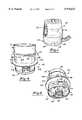
- FIG. 4is a side perspective view of the currently preferred embodiment of the motor housing.
- FIG. 5is a perspective view of the embodiment of FIG. 4 as seen from the lower portion of FIG. 4.
- FIG. 6is a cross section taken along the line 6--6 in FIG. 4.
- FIG. 7is a cross section taken along the line 7--7 in FIG. 7.
- FIG. 1diagrammatically illustrates a vacuum cleaner 20 having an exterior body 22.
- the lower end of the vacuum cleaner 20includes a debris collection portion 24.
- the preferred embodiment of this inventionis a liquid bath vacuum cleaner and, therefore, the debris collection portion includes a pan 26 that holds a selected volume of liquid 28.
- An inlet 29provides the opening through which debris is drawn into the vacuum cleaner.
- a motor housing 30is supported within the vacuum cleaner body 22 above the debris collection portion 24. As can be seen in FIG. 2, the motor housing 30 includes a main housing wall 32 that is generally open at both ends. It is useful to consider the motor housing 30 as having three portions.
- a first portion of the housing 30 at the bottom of the drawingsupports a separator 34 that rotates with a shaft 36 about its central longitudinal axis 38.
- the separator 34operates in a conventional manner to insure that debris that is drawn in through the inlet 29 remains in the debris collecting portion 24 and does not protrude into other portions of the motor housing 30.
- a labyrinth seal 40 and an air deflector 42further insure that the liquid 28 and any debris drawn in through the inlet 29 remain in the debris collecting portion 24.
- Additional sealing propertiesare provided by a sealing bearing 44, which is positioned at an interface between the rotating shaft 36 and a first portion 46 of the motor housing 30.
- the first portion 46preferably is positioned immediately adjacent the debris collecting portion 24 and supports the sealing elements 40-44 and the separator 34.
- a second portion 48 of the motor housing 30contains a motor chamber 50. Sidewalls of the motor chamber 50 define an interior surface 52 and an exterior surface 54.
- the preferred embodimentincludes an electric motor 56 supported within the motor chamber 50 so that when power is supplied to the motor 56, it drives or rotates the elongated shaft 36.
- a first airwayis provided between the exterior surface 54 of the motor chamber and the interior surface of the main housing wall 32.
- two such airways 60are positioned on opposite sides of the motor housing 30.
- each of the airways 60extends over approximately one quarter of the outer surface 54 of the motor chamber 50.
- the motor 56 and the motor chamber 50are positioned between the debris collecting portion 24 and the main fan assembly 72.
- the main fan assembly 72is driven by the motor 56 so that as the shaft 36 rotates, the fan assembly 72 operates.
- Fan assembly 72can be any conventional fan arrangement but preferably includes a plurality of channels 74 as generally illustrated and as are known in the art.
- the working air flow 76flows through the inlet 29, the separator 34 and along the airway defined by the chambers 60 on either side of the motor chamber 50.
- the working air flow 76then snakes through the channels 74 of the main fan assembly 72 and is exhausted through an opening 78 at the top (according to the drawing) end of the motor housing 30.
- the vacuum cleaner body 22preferably includes a plurality of venting slots or openings that allow the working air flow to escape outside of the vacuum cleaner and into the atmosphere.
- the venting slots in the body 22can be louvered slots or other openings specifically designed for aesthetic appearance, for example.
- FIG. 3is a cross-sectional view of the preferred embodiment of this invention taken 90° away from the illustration of FIG. 2.
- the preferred shape of the motor housing 30provides that the first airway 60 is not visible within the cross section of FIG. 3.
- a second airwayis provided through the motor chamber 50.
- a pair of inlets 80 and 82preferably are defined at the lower end (according to the drawing) of the second portion 48 of the motor housing 30.
- the inlets 80 and 82are formed as openings through the main housing wall 32 at an end of the second portion 48 that is near the first portion 46.
- the exterior surface 54 of the motor chamber 50is coincident with the exterior surface of the main housing wall 32.
- a pair of venting outlets 84 and 86are defined at an opposite end of the second portion 48 and preferably are offset from each other (see FIG. 6).
- the openings for the venting outlets 84 and 86are at least partially defined in the main housing wall 32.
- a second fan assembly 88is supported within the motor chamber 50 and is driven by the motor 56 as it causes the shaft 36 to rotate. As the second fan assembly 88 operates, it draws air into the openings 80 and 82 and creates an air flow 90 that flows through the windings of the motor 56 and exits the motor chamber 50 through the venting outlets 84 and 86.
- the air flow 90is the main cooling air flow since it moves through the motor chamber 50 and directly passes over the windings of the motor 56.
- the first portion 46preferably includes a generally cylindrical portion of the main housing wall 32.
- a cross bar 100includes a central portion 102 that provide the support for the separator 34 and the sealing components 40-44.
- the second portion 48preferably includes an irregularly shaped outside surface. Specifically, a pair of generally curved or rounded sidewalls 104 and 106 are opposite from each other and extend between a pair of generally flat or planar sidewalls 108 and 110.
- the motor chamber 50preferably has a generally rectangular cross section over a substantial portion of its length. The end of the motor chamber that faces toward the first portion 46 of the housing 30 preferably is somewhat rounded in contour and converges as a bottleneck toward the circular portion 102.
- the motor chamber 50is defined within the motor housing main wall 32.
- the two sidewalls 108 and 110 of the motor chamber 50are coincident with and the same as the sidewalls 108 and 110 of the overall motor housing 30.
- the exterior surface 54 on the motor chamber 50is the same as the exterior surface on the two sidewalls 108 and 110.
- the sidewalls 104 and 106are spaced radially outward from the exterior surface 54 on the corresponding sidewalls of the motor chamber 50. The spacing between sidewalls 104 and 106 and the exterior surface 54 on the motor chamber 50 defines the first airway 60 through which the working airflow 76 passes during vacuum cleaner operation.
- the working air flow 76passes along at least a portion of the exterior surface 54 of the motor chamber 50, it provides a secondary cooling effect for the motor 56.
- the preferred embodiment of this inventiontherefore, places the main fan assembly 72 above (according to the drawings) the motor chamber 50 so that the working air flow flows along the exterior surface 54 of the motor chamber 50 prior to being exhausted through the fan assembly itself.
- the venting outlet 86is off-center on the sidewall 108.
- the venting outlet 84 on the sidewall 110is similarly off-center relative to the center of that sidewall.
- the venting outlets 84 and 86preferably are offset from each other.
- This arrangementprovides a more efficient cooling air flow through the motor chamber 50.
- the preferred embodimentprovides the same cooling effect as prior designs using a reduced air flow.
- the motor housing designed according to this inventionachieves the same amount of motor cooling as other designs while using only 75% of the air flow. Specifically, it has been determined that a flow of 12 cubic feet per minute of air flow through the motor housing 50 has the same cooling effect as 16 cubic feet per minute in other designs.
- this inventionprovides an arrangement where efficient motor cooling is achieved while requiring less air flow and, therefore, using less energy. This provides the further advantage of being able to use a wider variety of components for the second fan assembly 88, for example.
- the second portion 48 of the housing 30preferably includes a radially outwardly extending flange 120 that serves as a motor housing mount that is supported within the vacuum cleaner body 22. Given this description, those skilled in the art will be able to provide a suitable mounting arrangement to maintain the motor housing 30 within a desired position within the vacuum cleaner body 22.
Landscapes
- Electric Suction Cleaners (AREA)
Abstract
Description
Claims (17)
Priority Applications (1)
| Application Number | Priority Date | Filing Date | Title |
|---|---|---|---|
| US09/018,068US5974623A (en) | 1998-02-04 | 1998-02-04 | Vacuum cleaner motor housing |
Applications Claiming Priority (1)
| Application Number | Priority Date | Filing Date | Title |
|---|---|---|---|
| US09/018,068US5974623A (en) | 1998-02-04 | 1998-02-04 | Vacuum cleaner motor housing |
Publications (1)
| Publication Number | Publication Date |
|---|---|
| US5974623Atrue US5974623A (en) | 1999-11-02 |
Family
ID=21786075
Family Applications (1)
| Application Number | Title | Priority Date | Filing Date |
|---|---|---|---|
| US09/018,068Expired - Fee RelatedUS5974623A (en) | 1998-02-04 | 1998-02-04 | Vacuum cleaner motor housing |
Country Status (1)
| Country | Link |
|---|---|
| US (1) | US5974623A (en) |
Cited By (17)
| Publication number | Priority date | Publication date | Assignee | Title |
|---|---|---|---|---|
| US6320292B1 (en)* | 1999-06-17 | 2001-11-20 | Matsushita Electric Industrial Co., Ltd. | Electric motor assembly |
| US6452297B2 (en)* | 2000-03-22 | 2002-09-17 | Asmo Co., Ltd. | Motor device having commutator and brush outside yoke |
| US6581241B2 (en) | 2001-06-21 | 2003-06-24 | Black & Decker Inc. | Vacuum cleaner having airflow recirculation path for cooling beater brush motor |
| US20030145426A1 (en)* | 2002-02-07 | 2003-08-07 | Jesus Fernandez-Grandizo Martinez | Vacuum cleaner cooling system |
| US20050022337A1 (en)* | 2003-07-31 | 2005-02-03 | Roney Jeffrey T. | Motor enclosure for a vacuum cleaner |
| US20060045143A1 (en)* | 2004-08-24 | 2006-03-02 | Serguei Anikitchev | Wavelength-locked fiber-coupled diode-laser bar |
| US20060093500A1 (en)* | 2004-11-04 | 2006-05-04 | Hesheng Liang | Blower |
| USD534325S1 (en) | 2004-11-29 | 2006-12-26 | Alto U.S. Inc. | Collection device with self sealing retention system |
| US20090019663A1 (en)* | 2007-02-12 | 2009-01-22 | David Rowntree | Vacuum cleaners |
| US20110005029A1 (en)* | 2009-07-08 | 2011-01-13 | Samsung Gwangju Electronics Co. Ltd. | Fan motor unit and vacuum cleaner having the same |
| USD693068S1 (en)* | 2012-02-02 | 2013-11-05 | Foshan Shunde Xinshengyuan Electrical Applicances Co., Ltd. | Pet hair dryer |
| US20160113467A1 (en)* | 2014-10-22 | 2016-04-28 | Dyson Technology Limited | Vacuum cleaner with motor cooling |
| JP2019508117A (en)* | 2016-03-31 | 2019-03-28 | エルジー エレクトロニクス インコーポレイティド | Vacuum cleaner |
| US10244912B2 (en) | 2014-10-22 | 2019-04-02 | Dyson Technology Limited | Vacuum cleaner with motor between separation stages |
| US10912432B2 (en) | 2016-03-31 | 2021-02-09 | Lg Electronics Inc. | Cleaner |
| US11166608B2 (en) | 2016-03-31 | 2021-11-09 | Lg Electronics Inc. | Cleaner |
| US11172798B2 (en) | 2016-03-31 | 2021-11-16 | Lg Electronics Inc. | Cleaner |
Citations (16)
| Publication number | Priority date | Publication date | Assignee | Title |
|---|---|---|---|---|
| US2272985A (en)* | 1939-10-14 | 1942-02-10 | Spencer Turbine Co | Motor mounting for vacuum cleaners |
| US2314334A (en)* | 1940-11-06 | 1943-03-23 | Apex Electrical Mfg Co | Suction cleaner |
| US2987241A (en)* | 1956-12-13 | 1961-06-06 | Electrolux Ab | Motor-fan unit mounting for suction cleaner |
| US3780397A (en)* | 1973-01-03 | 1973-12-25 | Singer Co | Wet/dry suction cleaner |
| US3866263A (en)* | 1973-04-17 | 1975-02-18 | Hoover Co | Cleaner with auxiliary air flow |
| US4633543A (en)* | 1984-11-09 | 1987-01-06 | Royal Appliance Mfg. Co. | Hand vacuum cleaner |
| US4640697A (en)* | 1985-10-01 | 1987-02-03 | Rexair, Inc. | Vacuum cleaner construction |
| US4824333A (en)* | 1985-10-01 | 1989-04-25 | Rexair, Inc. | Air blower assembly for vacuum cleaners |
| US4864683A (en)* | 1988-12-23 | 1989-09-12 | Ryobi Motor Products Corp. | Noise isolating motor mounting system for a canister vacuum cleaner |
| US4978281A (en)* | 1988-08-19 | 1990-12-18 | Conger William W Iv | Vibration dampened blower |
| JPH0490733A (en)* | 1990-08-06 | 1992-03-24 | S I T:Kk | Cleaner |
| US5421058A (en)* | 1993-10-01 | 1995-06-06 | Royal Appliance Mfg. Co. | Hand-held vacuum cleaner |
| US5448794A (en)* | 1993-09-16 | 1995-09-12 | Electrolux Corporation | Corded handheld vacuum cleaner |
| US5479676A (en)* | 1994-05-12 | 1996-01-02 | Electrolux Corporation | Vacuum cleaner |
| US5592716A (en)* | 1993-11-02 | 1997-01-14 | Aktiebolaget Electrolux | Device for a vacuum cleaner and a method for cooling a motor |
| US5638575A (en)* | 1995-05-24 | 1997-06-17 | Techtronic Industries Co., Ltd. | Vacuum cleaners |
- 1998
- 1998-02-04USUS09/018,068patent/US5974623A/ennot_activeExpired - Fee Related
Patent Citations (16)
| Publication number | Priority date | Publication date | Assignee | Title |
|---|---|---|---|---|
| US2272985A (en)* | 1939-10-14 | 1942-02-10 | Spencer Turbine Co | Motor mounting for vacuum cleaners |
| US2314334A (en)* | 1940-11-06 | 1943-03-23 | Apex Electrical Mfg Co | Suction cleaner |
| US2987241A (en)* | 1956-12-13 | 1961-06-06 | Electrolux Ab | Motor-fan unit mounting for suction cleaner |
| US3780397A (en)* | 1973-01-03 | 1973-12-25 | Singer Co | Wet/dry suction cleaner |
| US3866263A (en)* | 1973-04-17 | 1975-02-18 | Hoover Co | Cleaner with auxiliary air flow |
| US4633543A (en)* | 1984-11-09 | 1987-01-06 | Royal Appliance Mfg. Co. | Hand vacuum cleaner |
| US4640697A (en)* | 1985-10-01 | 1987-02-03 | Rexair, Inc. | Vacuum cleaner construction |
| US4824333A (en)* | 1985-10-01 | 1989-04-25 | Rexair, Inc. | Air blower assembly for vacuum cleaners |
| US4978281A (en)* | 1988-08-19 | 1990-12-18 | Conger William W Iv | Vibration dampened blower |
| US4864683A (en)* | 1988-12-23 | 1989-09-12 | Ryobi Motor Products Corp. | Noise isolating motor mounting system for a canister vacuum cleaner |
| JPH0490733A (en)* | 1990-08-06 | 1992-03-24 | S I T:Kk | Cleaner |
| US5448794A (en)* | 1993-09-16 | 1995-09-12 | Electrolux Corporation | Corded handheld vacuum cleaner |
| US5421058A (en)* | 1993-10-01 | 1995-06-06 | Royal Appliance Mfg. Co. | Hand-held vacuum cleaner |
| US5592716A (en)* | 1993-11-02 | 1997-01-14 | Aktiebolaget Electrolux | Device for a vacuum cleaner and a method for cooling a motor |
| US5479676A (en)* | 1994-05-12 | 1996-01-02 | Electrolux Corporation | Vacuum cleaner |
| US5638575A (en)* | 1995-05-24 | 1997-06-17 | Techtronic Industries Co., Ltd. | Vacuum cleaners |
Cited By (48)
| Publication number | Priority date | Publication date | Assignee | Title |
|---|---|---|---|---|
| US6320292B1 (en)* | 1999-06-17 | 2001-11-20 | Matsushita Electric Industrial Co., Ltd. | Electric motor assembly |
| US6452297B2 (en)* | 2000-03-22 | 2002-09-17 | Asmo Co., Ltd. | Motor device having commutator and brush outside yoke |
| US6581241B2 (en) | 2001-06-21 | 2003-06-24 | Black & Decker Inc. | Vacuum cleaner having airflow recirculation path for cooling beater brush motor |
| US20030145426A1 (en)* | 2002-02-07 | 2003-08-07 | Jesus Fernandez-Grandizo Martinez | Vacuum cleaner cooling system |
| US6807709B2 (en) | 2002-02-07 | 2004-10-26 | Koblenz Electrica, S.A. De C.V. | Vacuum cleaner cooling system |
| US7614113B2 (en) | 2003-07-31 | 2009-11-10 | Panasonic Corporation Of North America | Motor enclosure for a vacuum cleaner |
| US20050022337A1 (en)* | 2003-07-31 | 2005-02-03 | Roney Jeffrey T. | Motor enclosure for a vacuum cleaner |
| US7921510B2 (en) | 2003-07-31 | 2011-04-12 | Panasonic Corporation Of North America | Motor enclosure for a vacuum cleaner |
| US20090293222A1 (en)* | 2003-07-31 | 2009-12-03 | Roney Jeffrey T | Motor enclosure for a vacuum cleaner |
| US20060045143A1 (en)* | 2004-08-24 | 2006-03-02 | Serguei Anikitchev | Wavelength-locked fiber-coupled diode-laser bar |
| US7780423B2 (en)* | 2004-11-04 | 2010-08-24 | Sun Pleasure Company, Ltd. | Blower |
| US20100322792A1 (en)* | 2004-11-04 | 2010-12-23 | Sun Pleasure Company Ltd. | Blower |
| US20060093500A1 (en)* | 2004-11-04 | 2006-05-04 | Hesheng Liang | Blower |
| USD534325S1 (en) | 2004-11-29 | 2006-12-26 | Alto U.S. Inc. | Collection device with self sealing retention system |
| US20090019663A1 (en)* | 2007-02-12 | 2009-01-22 | David Rowntree | Vacuum cleaners |
| US8028373B2 (en) | 2007-02-12 | 2011-10-04 | Black & Decker Inc. | Vacuum cleaners |
| US8918952B2 (en) | 2007-02-12 | 2014-12-30 | Black & Decker Inc. | Vacuum cleaner |
| US20110005029A1 (en)* | 2009-07-08 | 2011-01-13 | Samsung Gwangju Electronics Co. Ltd. | Fan motor unit and vacuum cleaner having the same |
| US8413294B2 (en)* | 2009-07-08 | 2013-04-09 | Samsung Electronics Co., Ltd. | Fan motor unit and vacuum cleaner having the same |
| USD693068S1 (en)* | 2012-02-02 | 2013-11-05 | Foshan Shunde Xinshengyuan Electrical Applicances Co., Ltd. | Pet hair dryer |
| US10244912B2 (en) | 2014-10-22 | 2019-04-02 | Dyson Technology Limited | Vacuum cleaner with motor between separation stages |
| US20160113467A1 (en)* | 2014-10-22 | 2016-04-28 | Dyson Technology Limited | Vacuum cleaner with motor cooling |
| AU2015334721B2 (en)* | 2014-10-22 | 2018-11-08 | Dyson Technology Limited | Vacuum cleaner with motor cooling |
| US10016111B2 (en)* | 2014-10-22 | 2018-07-10 | Dyson Technology Limited | Vacuum cleaner with motor cooling |
| US11172798B2 (en) | 2016-03-31 | 2021-11-16 | Lg Electronics Inc. | Cleaner |
| US11229337B2 (en) | 2016-03-31 | 2022-01-25 | Lg Electronics Inc. | Cleaner |
| US10939789B2 (en) | 2016-03-31 | 2021-03-09 | Lg Electronics Inc. | Cleaner |
| US10945573B2 (en) | 2016-03-31 | 2021-03-16 | Lg Electronics Inc. | Cleaner |
| US10980380B2 (en) | 2016-03-31 | 2021-04-20 | Lg Electronics Inc. | Cleaner |
| US11116368B2 (en) | 2016-03-31 | 2021-09-14 | Lg Electronics Inc. | Cleaner |
| US11147422B2 (en) | 2016-03-31 | 2021-10-19 | Lg Electronics Inc. | Cleaner |
| US11166608B2 (en) | 2016-03-31 | 2021-11-09 | Lg Electronics Inc. | Cleaner |
| US11166607B2 (en) | 2016-03-31 | 2021-11-09 | Lg Electronics Inc. | Cleaner |
| JP2019508117A (en)* | 2016-03-31 | 2019-03-28 | エルジー エレクトロニクス インコーポレイティド | Vacuum cleaner |
| US11179015B2 (en) | 2016-03-31 | 2021-11-23 | Lg Electronics Inc. | Cleaner |
| US10912432B2 (en) | 2016-03-31 | 2021-02-09 | Lg Electronics Inc. | Cleaner |
| US11426039B2 (en) | 2016-03-31 | 2022-08-30 | Lg Electronics Inc. | Cleaner |
| US11844486B2 (en) | 2016-03-31 | 2023-12-19 | Lg Electronics Inc. | Cleaner |
| US11937758B2 (en) | 2016-03-31 | 2024-03-26 | Lg Electronics Inc. | Cleaner |
| US11963654B2 (en) | 2016-03-31 | 2024-04-23 | Lg Electronics Inc. | Cleaner |
| US11992169B2 (en) | 2016-03-31 | 2024-05-28 | Lg Electronics Inc. | Cleaner |
| US12004701B2 (en) | 2016-03-31 | 2024-06-11 | Lg Electronics Inc. | Cleaner |
| US12011135B2 (en) | 2016-03-31 | 2024-06-18 | Lg Electronics Inc. | Cleaner |
| US12053137B2 (en) | 2016-03-31 | 2024-08-06 | Lg Electronics Inc. | Cleaner |
| US12064079B2 (en) | 2016-03-31 | 2024-08-20 | Lg Electronics Inc. | Cleaner |
| US12070179B2 (en) | 2016-03-31 | 2024-08-27 | Lg Electronics Inc. | Cleaner |
| US12121199B2 (en) | 2016-03-31 | 2024-10-22 | Lg Electronics Inc. | Cleaner |
| US12318056B2 (en) | 2016-03-31 | 2025-06-03 | Lg Electronics Inc. | Cleaner |
Similar Documents
| Publication | Publication Date | Title |
|---|---|---|
| US5974623A (en) | Vacuum cleaner motor housing | |
| KR100732598B1 (en) | Ventilation device and rail traction electric motor equipped with such a device | |
| JP3720452B2 (en) | Range hood fan | |
| KR101049433B1 (en) | Air conditioner | |
| US7374408B2 (en) | Engine cooling fan motor with reduced water entry protection | |
| JP2003009461A (en) | Bypass discharge motor assembly, muffler for motor assembly, and cooling fan housing for motor assembly | |
| US7677865B2 (en) | Air purifier | |
| CN214017410U (en) | Air duct structure of sweeping robot | |
| US6503065B2 (en) | Engine blower | |
| US6294852B1 (en) | Motor cover arrangement | |
| JPH1026099A (en) | Electric blower | |
| GB2409635A (en) | Vacuum cleaner with reduced noise | |
| US6807709B2 (en) | Vacuum cleaner cooling system | |
| JP4029333B2 (en) | Electric blower | |
| JP2003240262A (en) | Supply and exhaust device for double tube | |
| JP3992722B2 (en) | Air conditioner | |
| KR200151233Y1 (en) | Air guiding device for an impeller motor | |
| KR100437037B1 (en) | Centrifugal fan of vacuum cleaner | |
| KR100408055B1 (en) | Structure for flowing air of fan-motor housing in vacuum cleaner | |
| JP3617216B2 (en) | Electric blower | |
| CN217354834U (en) | Cabinet type centrifugal fan | |
| JPH04330399A (en) | Motor-operated blower for vacuum cleaner | |
| JPS6153499A (en) | Blower | |
| JPH07324698A (en) | Motor cooling structure for single suction centrifugal fan | |
| KR100479560B1 (en) | Vehicle Engine Cooling System |
Legal Events
| Date | Code | Title | Description |
|---|---|---|---|
| AS | Assignment | Owner name:REXAIR, INC., MICHIGAN Free format text:ASSIGNMENT OF ASSIGNORS INTEREST;ASSIGNORS:CUMMINS, CRAIG RICHARD;ROHN, DEAN ROBERT;REEL/FRAME:009291/0333 Effective date:19980409 | |
| AS | Assignment | Owner name:BANK OF AMERICA, N.A., NORTH CAROLINA Free format text:SECURITY INTEREST;ASSIGNOR:REXAIR, INC.;REEL/FRAME:010742/0154 Effective date:20000324 | |
| AS | Assignment | Owner name:BANK OF AMERICA, N.A., NORTH CAROLINA Free format text:SECURITY INTEREST;ASSIGNOR:REXAIR, INC.;REEL/FRAME:013821/0964 Effective date:20030227 Owner name:VANASKY, DAVID A., DELAWARE Free format text:SECURITY INTEREST;ASSIGNOR:REXAIR, INC.;REEL/FRAME:013821/0964 Effective date:20030227 Owner name:WILMINGTON TRUST COMPANY, DELAWARE Free format text:SECURITY INTEREST;ASSIGNOR:REXAIR, INC.;REEL/FRAME:013821/0964 Effective date:20030227 | |
| REMI | Maintenance fee reminder mailed | ||
| AS | Assignment | Owner name:FLEET CAPITAL CORPORATION, AS AGENT, ILLINOIS Free format text:CONFIRMATORY PATENT SECURITY AGREEMENT;ASSIGNORS:JACUZZI BRANDS, INC.;BATHCRAFT, INC.;ELJER PLUMBINGWARE, INC.;AND OTHERS;REEL/FRAME:013813/0013 Effective date:20030715 | |
| AS | Assignment | Owner name:REXAIR, INC., FLORIDA Free format text:RELEASE OF SECURITY INTEREST IN INTELLECTUAL PROPERTY;ASSIGNOR:BANK OF AMERICA, N.A., AS COLLATERAL AGENT;REEL/FRAME:014409/0253 Effective date:20030715 | |
| LAPS | Lapse for failure to pay maintenance fees | ||
| AS | Assignment | Owner name:WILMINGTON TRUST COMPANY, AS COLLATERAL AGENT FOR Free format text:SECURITY INTEREST;ASSIGNOR:REXAIR, INC.;REEL/FRAME:014646/0976 Effective date:20030715 | |
| AS | Assignment | Owner name:REXAIR, INC., FLORIDA Free format text:RELEASE OF INTEREST IN INTELLECTUAL PROPERTY;ASSIGNOR:BANK OF AMERICA, N.A., AS AGENT;REEL/FRAME:014718/0203 Effective date:20030715 | |
| STCH | Information on status: patent discontinuation | Free format text:PATENT EXPIRED DUE TO NONPAYMENT OF MAINTENANCE FEES UNDER 37 CFR 1.362 | |
| FP | Lapsed due to failure to pay maintenance fee | Effective date:20031102 | |
| AS | Assignment | Owner name:REXAIR, INC., FLORIDA Free format text:RELEASE OF LIEN ON PATENTS;ASSIGNOR:WILMINGTON TRUST COMPANY, AS CLASS B COLLATERAL AGENT;REEL/FRAME:016245/0380 Effective date:20050630 Owner name:REXAIR, INC., FLORIDA Free format text:RELEASE OF LIEN ON PATENTS;ASSIGNOR:FLEET CAPITAL CORPORATION, AS ADMINISTRATIVE AGENT;REEL/FRAME:016245/0392 Effective date:20050630 | |
| AS | Assignment | Owner name:REXAIR, INC., FLORIDA Free format text:CORRECTIVE ASSIGNMENT TO CORRECT THE NAMES OF THE CONVEYING PARTY(IES) PREVIOUSLY RECORDED AT REEL 014718 FRAME 0203;ASSIGNORS:BANK OF AMERICA, N.A.;WILMINGTON TRUST COMPANY;VANASKEY, DAVID A.;REEL/FRAME:033390/0320 Effective date:20030715 |