US5972251A - Method for blocking a contact lens button - Google Patents
Method for blocking a contact lens buttonDownload PDFInfo
- Publication number
- US5972251A US5972251AUS08/941,719US94171997AUS5972251AUS 5972251 AUS5972251 AUS 5972251AUS 94171997 AUS94171997 AUS 94171997AUS 5972251 AUS5972251 AUS 5972251A
- Authority
- US
- United States
- Prior art keywords
- block
- cup
- end portion
- button
- spindle
- Prior art date
- Legal status (The legal status is an assumption and is not a legal conclusion. Google has not performed a legal analysis and makes no representation as to the accuracy of the status listed.)
- Expired - Lifetime
Links
Images


Classifications
- B—PERFORMING OPERATIONS; TRANSPORTING
- B24—GRINDING; POLISHING
- B24B—MACHINES, DEVICES, OR PROCESSES FOR GRINDING OR POLISHING; DRESSING OR CONDITIONING OF ABRADING SURFACES; FEEDING OF GRINDING, POLISHING, OR LAPPING AGENTS
- B24B13/00—Machines or devices designed for grinding or polishing optical surfaces on lenses or surfaces of similar shape on other work; Accessories therefor
- B24B13/005—Blocking means, chucks or the like; Alignment devices
- B—PERFORMING OPERATIONS; TRANSPORTING
- B29—WORKING OF PLASTICS; WORKING OF SUBSTANCES IN A PLASTIC STATE IN GENERAL
- B29D—PRODUCING PARTICULAR ARTICLES FROM PLASTICS OR FROM SUBSTANCES IN A PLASTIC STATE
- B29D11/00—Producing optical elements, e.g. lenses or prisms
- B29D11/00932—Combined cutting and grinding thereof
- B—PERFORMING OPERATIONS; TRANSPORTING
- B29—WORKING OF PLASTICS; WORKING OF SUBSTANCES IN A PLASTIC STATE IN GENERAL
- B29C—SHAPING OR JOINING OF PLASTICS; SHAPING OF MATERIAL IN A PLASTIC STATE, NOT OTHERWISE PROVIDED FOR; AFTER-TREATMENT OF THE SHAPED PRODUCTS, e.g. REPAIRING
- B29C2793/00—Shaping techniques involving a cutting or machining operation
- B29C2793/009—Shaping techniques involving a cutting or machining operation after shaping
- Y—GENERAL TAGGING OF NEW TECHNOLOGICAL DEVELOPMENTS; GENERAL TAGGING OF CROSS-SECTIONAL TECHNOLOGIES SPANNING OVER SEVERAL SECTIONS OF THE IPC; TECHNICAL SUBJECTS COVERED BY FORMER USPC CROSS-REFERENCE ART COLLECTIONS [XRACs] AND DIGESTS
- Y10—TECHNICAL SUBJECTS COVERED BY FORMER USPC
- Y10S—TECHNICAL SUBJECTS COVERED BY FORMER USPC CROSS-REFERENCE ART COLLECTIONS [XRACs] AND DIGESTS
- Y10S425/00—Plastic article or earthenware shaping or treating: apparatus
- Y10S425/808—Lens mold
Definitions
- the present inventionrelates to contact lens manufacturing, and more particularly relates to improved apparatus and methods for blocking a contact lens button (also termed a contact lens blank or precursor) for machining operations which form the button into a wearable contact lens.
- a contact lens buttonalso termed a contact lens blank or precursor
- contact lens buttonsmay be cut from rod stock or sheet material, or individually cast in cups using a curable liquid monomer. While it is possible to attach the button directly to the lathe chuck, this is not commonly done since the chuck of the lathe machine uses radial compression to hold the work piece in place for lathing, and as such could impart damaging forces to the optical characteristics of the button.
- the buttonis therefore more commonly mounted to one end of a separate metal pin or "block", the opposite end of the block being configured as a spindle for removable insertion into the chuck of the lathe.
- the buttonis typically adhered to the block with an adhesive or special type of wax called "pitch" (with the block thus commonly referred to as a “pitch block” in the art).
- a concave (or “base”) curveis lathed into the exposed end of the button opposite the adhered end.
- a second "ledge” cutmay be made in the outer cylindrical surface of the button for facilitating subsequent alignment with the front curve block, this cut typically termed a "base curve reference”.
- a "front curve” blockis then removably secured to the lathed base curve surface while attempting to maintain axial alignment with the first "base curve” block which is then removed from the button.
- the front curve blockis mounted to the lathe chuck for lathing the convex or front curve of the button to form the finished lens. Lens edging and polishing operations may also be performed on each surface of the lens prior to removal from each block.
- the present inventionaddresses the above problems with blocking a molded contact lens button by providing a block which may be integrally formed with a contact lens button when the button is molded in a casting cup. Since the block is formed integrally with the button when the button is made, there is no need for a separate blocking operation of the button to a base curve block as is now widely practiced in this art as discussed above. Furthermore, since the block is made of a machinable material, there is no need for removing the block from the button prior to lathing the front curve since the machinable base curve block is cut away immediately prior to or simultaneous with cutting of the front curve of the lens.
- the block of the inventionis preferably formed from a material which is readily machinable, e.g., a dimensionally stable resin such as polystyrene.
- the blockis basically comprised of two portions; a flat, circular carrier member to which a contact lens button attaches in the manner to be explained, and an elongated spindle extending from the center of the bottom surface of the carrier member, the opposite, free end of the spindle configured for removable attachment to the lathe chuck.
- a casting cupwhich is of generally cylindrical configuration having a bottom wall with a cylindrical side wall extending upwardly from the perimeter of the bottom wall, the upper perimeter of the cylindrical wall defining a top opening wherein liquid monomer may be poured into the cup.
- a circular apertureis formed through substantially the center of the bottom wall wherethrough the free end of the spindle of the machinable base curve block of the invention is passed from the top opening of the cup.
- the circular carrier member of the blockis also located within the casting cup, and preferably within the lower half of the cup.
- the circular carrier membermay be provided with a plurality of through holes arranged in annularly spaced relation thereabout such that the monomer flows through and occupies the space of the through holes.
- the carrier memberis preferably spaced from the bottom wall of the cup such that the liquid monomer also flows on both sides of the carrier member. It is noted the diameter of the aperture in the cup bottom wall is only very slightly larger than the diameter of the spindle section passing therethrough such that there is an interference fit between the two when the spindle is passed through the aperture. As such, leakage of the liquid monomer from the cup through the aperture is substantially prevented.
- the axis about which the button will be turned in a latheis defined by the spindle portion of the block. Since the spindle extends through a centrally located aperture in the casting cup, the portion of the spindle extending from the formed button lies substantially along the central axis of the cylindrical button. The free end of the spindle opposite the button may then be inserted into the chuck of a lathe for cutting the first base curve into the exposed end of the button. Once the base curve is cut, a front curve block may be adhered to the base curve surface which is done while maintaining axial alignment between the front curve block and the spindle.
- the free end of the front curve blockis attached to the chuck of a lathe for cutting the front, "power" curve of the lens.
- the base curve blockis machinable so it need not be removed from the button prior to cutting the front curve. Instead, the base curve block is simply cut away by the cutting blade either prior to or simultaneously with cutting of the front curve. This cut into the button is of a depth sufficient to cut away the circular carrier member which was formed integrally with the button in the cup.
- a measurementis made of the distance from the center of the base curve surface to a predetermined point along the spindle.
- a second measurementis taken between the predetermined point on the spindle of the base curve block and the stop of the chuck (which is readily determinable with a chuck known in the art as a "dead stop" chuck which includes a stop which limits the movement of the front curve block spindle into the chuck).
- This second measurementof course includes the front curve block and thickness of the pitch used to adhere the front curve block to the button.
- the base curve positioncan be readily determined by subtracting the first measurement from the second measurement, and thereby allowing the lathe to be set to cut the power curve to the desired thickness.
- the front curve blockis removed from the chuck and the finished lens by known methods. It is noted intermediate lens edging and polishing operations may be performed prior to removal of the lens from each of the blocks.
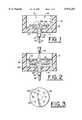
- FIG. 1is a side elevational view in section of the casting cup and base curve block of the invention in the attached condition according to a first preferred embodiment
- FIG. 2is the view of FIG. 1 showing liquid monomer being dispensed within the cup;
- FIG. 3is a top plan view of the base curve block of the invention according to the embodiment in FIG. 1;
- FIG. 4is a side elevational view in section showing the cured button and base curve block combination from FIG. 2 secured to a lathe chuck with a cutting tool (both fragmented) positioned for cutting the base curve in the button;
- FIG. 5is a side elevational view of the button and base curve block removed from the base curve lathe of FIG. 4 and mounted to a front curve block attached to a dead-stop chuck, with the cutting tool shown positioned for cutting the power curve of the lens through the base curve block;
- FIG. 6is a top plan view of the base curve block of the invention according to a second embodiment
- FIG. 7is a side elevational view in section of the casting cup and block in the attached condition according to a second embodiment
- FIG. 8is a side elevational view in section of the casting cup and block in the attached condition according to a third embodiment.
- FIG. 9is a side elevational view in section of the casting cup and block in the attached condition according to yet another embodiment.
- Cup 10includes a generally circular bottom wall 14 and a cylindrical side wall 16 extending upwardly therefrom defining an open top 18.
- An aperture 20is formed entirely through substantially the center of bottom wall 14, through which the free end 22 of spindle portion 24 of the base curve block 12 is passed from open top 18 to attach block 12 to cup 10.
- Base curve block 12is machinable as described so that block 12 can be cut completely away prior to or simultaneously with the power curve cutting operation (as will be described more fully below).
- a suitable material for base curve block 12is a dimensionally stable resin such as polystyrene, for example. It is intended cup 10 be disposable and formed of a resin which is compatible with liquid lens material; a suitable material for cup 10 would be polypropylene, for example.
- Base curve block 12is comprised of two main portions; a spindle portion 24 and an integral circular carrier portion 26, with spindle portion 24 perpendicularly extending from substantially the center of the bottom surface 27 thereof.
- Spindle 24could be made of a constant diameter along its total length; however, in the preferred embodiment, spindle 24 is configured with three sections 28, 30 and 32 of increasingly reduced diameter from bottom surface 27 to the spindle free end 22, respectively.
- the diameter of center section 24is only very slightly smaller than the diameter of aperture 20 so as to provide an interference fit between the two as spindle 12 is passed through aperture 20.
- the juncture between spindle sections 28 and 30form a shoulder 34 which firmly abuts the top surface 15 of bottom wall 14 adjacent aperture 20 when spindle 12 is fully inserted through aperture 20.
- the circular carrier portion 26lies in a plane spaced and parallel to bottom wall surface 15 which acts to enhance the mechanical connection between carrier member 26 and the hardened button since the liquid monomer 36 will flow beneath and above carrier member 26.
- the length of spindle section 28is chosen so that carrier portion 26 is spaced only a small distance from bottom wall surface 15, and is preferably a distance less than half the depth DI of the cup internal cavity 19.
- Other meansmay be employed to enhance the mechanical connection between block 12 and button 38, either alternately or in addition to the spacing of carrier member 26 above bottom wall 14.
- aperture 20is effectively sealed by spindle section 24 such that a quantity of liquid monomer 36 may be dispensed into cavity 19 with no appreciable leakage through aperture 20 (FIG. 2).
- additional carrier member to monomer mechanical securing meanstake the form of a plurality of apertures 29 formed entirely therethrough in annularly spaced relation thereabout. As such, the liquid monomer 36 passes through these apertures 29, as well as between carrier portion 26 and bottom wall surface 15 thereby firmly securing block 12 to the finished button 38 (FIGS. 4 and 5) as the monomer 36 cures.
- FIG. 6illustrates yet another embodiment of the block.
- the spindle portion of base curve block 112may be essentially the same as the embodiment shown in FIG. 3, however, the carrier member 126 includes projections 125 spaced about its periphery to facilitate securing cured monomer to carrier member 126.
- cup 10may be made flexible to facilitate ejection of button 38 and block 12 therefrom.
- block 12could be suspended upside down with carrier member 26 located in the top half of cup 10 until the monomer is fully set.
- buttons 38 and 38are substantially coplanar with shoulder 34, with spindle sections 30 and 32 extending perpendicularly from the center of bottom button surface 39.
- Smallest diameter section 32 having free end 22is configured for releasable attachment to a chuck 40 of a lathe machine(not shown).
- shoulder 33 of spindle 12(formed at the juncture of sections 30 and 32) firmly abuts the end surface 41 of the chuck 40.
- a cutting tool 42is applied to top button surface 43 to cut the concave base curve 44 in button 38.
- section 30 or 32may include a keyway or analogous structure for registering the rotational position of block/button assembly with respect to chuck 40 of the lathe; this is useful when cutting rotationally asymmetric curves into the button. If desired, a polishing operation may be performed on surface 44 at this time either while still attached to chuck 40, or transferred to a polishing station having a separate chuck for turning the workpiece.
- spindle 24defines the axis x--x about which button 38 is turned as the base curve 44 is cut. This axis x--x substantially coincides with the true central longitudinal axis of button 38 since aperture 20 is formed at substantially the center of bottom wall 14 of cup 10 which forms button 38.
- button 38is shown attached to another lathe for cutting of the front power curve of the lens.
- a first measurement L 1is taken from spindle juncture 33 to the lowest point 45 of base curve surface 44.
- Conventional front curve block 46is then affixed with pitch 48 to the base curve 44 of button 38 while maintaining axial alignment with axis x--x.
- the free end of spindle 47is inserted and removably secured into a dead-stop chuck 50 of a lathe (not shown).
- a second measurement L 2is then taken from the internal stop 51 of chuck 50 to spindle juncture 33; L 2 -L 1 thus gives the distance D 2 from stop 51 to base curve surface point 45.
- the lathemay then be programmed to cut the front power curve 52 to the desired thickness as measured out from base curve point 45. It is noted that any other predetermined point on spindle 20 may be chosen from which the measurements are taken (e.g., the free end 22 thereof).
- the above-described preferred embodimentrelates primarily to methods involving molding, and subsequently lathing, a contact lens button having a cylindrical shape and integrated with a block for removable attachment to a lathe chuck.
- the inventionis also applicable to methods involving molding, and subsequently lathing, a semi-finished contact lens button, i.e., methods where a contact lens button is first molded integral with the block so as provide a semi-finished button with one lens surface, and subsequently the opposite surface of the button is lathed to obtain an article with a final contact lens shape.
- FIG. 7is a side elevational view in section of the casting cup and block for casting a semi-finished button having a "molded-in" front surface.
- casting cup 110may have the same general construction as cup 10 in the previously described embodiments, including a generally circular bottom wall 114, with aperture 120 formed entirely therethrough, and a cylindrical side wall 116.
- Block 112may be formed of materials as desired for block 12.
- Block 112comprises a spindle portion 124 and an integral circular carrier portion 126, with spindle portion 124 perpendicularly extending from substantially the center of the bottom surface 127 thereof.
- Spindle 24preferably is configured with three sections 128, 130 and 132 of increasingly reduced diameter from bottom surface 27 to the spindle free end 122, respectively.
- Center section 124provides an interference fit with aperture 120, with spindle section 128 acting as a stop to prevent further advancement of spindle 112 through aperture 120.
- the bottom surface 127 of carrier member 126lies in a plane spaced and parallel to bottom wall surface 115, such that liquid monomer 36 can fill this space between surface 127 and carrier member 126 when dispensed in the cavity of cup 110.
- Projections 125are adequately spaced from the inner surfaces of cup cylindrical wall 116 to permit liquid monomer 36 to fill this space, it being further noted that liquid monomer can flow between interstices between individual projections 125. As discussed previously with reference to FIG. 6, projections 125 facilitate securing cured monomer to carrier member 126.
- carrier member 126 of block 112includes upper concave surface 154 which has the desired shape of the front contact lens surface.
- the resultant buttonwhen monomer 36 is cured, includes a convex molded-in front surface formed against surface 154, whereby it is unnecessary to lathe cut the front lens surface.
- this semi-finished buttonis secured to block 112 for a subsequent lathing operation of the back lens surface.
- Surface 154may be spherical, aspherical or toric and may include multiple curves as in conventional front surface contact lens designs.
- section 132may be inserted into the chuck of a lathe mechanism for cutting the back lens surface (base curve) from the button. If desired, some excess cured lens material can be removed before cutting the back lens surface, so long as the button remains secured to block 112. The depth of the cut for the back lens surface is controlled to ensure desired thickness across the surface of the lens. Then, a desired lens edge profile can be cut to form the final lens-shaped article, followed by removal of the finished lens from block 112. (Alternately, surface 154 may be shaped so as to form a contact lens edge portion when monomer is cured, thus eliminating or partially eliminating the need to lathe the edge profile.)
- FIG. 8illustrates another embodiment for initially molding a semi-finished button.
- casting cup 210may have the same general construction as in the previously described embodiments.
- Block 212may be formed of materials as desired for block 12 or block 112.
- Block 212similar comprises a spindle portion 224 and an integral circular carrier portion 226, with spindle portion 224 perpendicularly extending from substantially the center of the bottom surface 227 thereof.
- the bottom surface 227 of carrier member 226is spaced from and parallel to bottom wall surface 215, such that liquid monomer 36 can fill this space between surface 227 and carrier member 226 when dispensed in the cavity of cup 210.
- Projections 225are included on carrier member 226, as in other embodiments, and adequately spaced from the inner surfaces of cup cylindrical wall 216 to permit liquid monomer 36 to fill this space.
- carrier member 226 of block 212includes upper convex surface 254 which has the desired shape of the back contact lens surface. Accordingly, when monomer 36 is cured, the resultant button includes a concave molded-in back surface formed against surface 254, whereby it is unnecessary to lathe cut the back lens surface. As in the previous embodiments, this semi-finished button is secured to block 212 for a subsequent lathing operation of the front lens surface.
- Surface 254may be spherical, aspherical or toric and may include multiple curves as in conventional back surface contact lens designs, and optionally, surface 254 may be shaped so as to form a contact lens edge portion when monomer is cured.
- section 232may be inserted into the chuck of a lathe mechanism for cutting the front lens surface (power curve) from the button. If desired, some excess cured lens material may be removed from the button prior to cutting the front lens surface. The depth of the cut for the front lens surface is controlled to ensure desired thickness across the surface of the lens. Then, a desired lens edge profile can be cut to form the final lens-shaped article, followed by removal of the finished lens from block 212.
- FIG. 9illustrates yet another embodiment of the invention.
- Casting cup 310includes a generally circular bottom wall 314 and a cylindrical side wall 316. This embodiment is particularly useful where casting cup 310 is made of a plastic having sufficient transparency so that monomer 36 can be cured by exposure to an ultraviolet light source positioned below bottom wall 314, i.e., ultraviolet light is transmitted through bottom wall 314 to monomer 36 containing in casting cup 310.
- Block 312may be formed of materials as desired for block 12.
- Block 312comprises a spindle portion 324 and an integral circular carrier portion 326 that includes projections 325 (analogous to the embodiment shown in FIG. 6), with spindle portion 324 perpendicularly extending from substantially the center of the upper surface 227 of the carrier portion.
- Spindle 324preferably includes section 332 and is engageable with a lathe chuck.
- Individual projections 325are spaced with interstices (as shown in FIG. 6) so that monomer 36 can be flow below carrier member 326.
- projections 325facilitate securing cured monomer to carrier member 126.
- the inner surface of cup cylindrical side wall 316include a detente 318, forming shoulder 319, so that projections 325 can rest on shoulder 319 while liquid monomer 36 is introduced into and then cured in the casting cup.
Landscapes
- Engineering & Computer Science (AREA)
- Mechanical Engineering (AREA)
- Health & Medical Sciences (AREA)
- Manufacturing & Machinery (AREA)
- Ophthalmology & Optometry (AREA)
- Eyeglasses (AREA)
- Casting Or Compression Moulding Of Plastics Or The Like (AREA)
- Grinding And Polishing Of Tertiary Curved Surfaces And Surfaces With Complex Shapes (AREA)
Abstract
Description
Claims (21)
Priority Applications (4)
| Application Number | Priority Date | Filing Date | Title |
|---|---|---|---|
| US08/941,719US5972251A (en) | 1996-10-16 | 1997-10-01 | Method for blocking a contact lens button |
| CA002267189ACA2267189C (en) | 1996-10-16 | 1997-10-16 | Apparatus and method for blocking a contact lens button |
| PCT/US1997/018595WO1998016368A1 (en) | 1996-10-16 | 1997-10-16 | Apparatus and method for blocking a contact lens button |
| AU48215/97AAU4821597A (en) | 1996-10-16 | 1997-10-16 | Apparatus and method for blocking a contact lens button |
Applications Claiming Priority (2)
| Application Number | Priority Date | Filing Date | Title |
|---|---|---|---|
| US2896796P | 1996-10-16 | 1996-10-16 | |
| US08/941,719US5972251A (en) | 1996-10-16 | 1997-10-01 | Method for blocking a contact lens button |
Publications (1)
| Publication Number | Publication Date |
|---|---|
| US5972251Atrue US5972251A (en) | 1999-10-26 |
Family
ID=26704319
Family Applications (1)
| Application Number | Title | Priority Date | Filing Date |
|---|---|---|---|
| US08/941,719Expired - LifetimeUS5972251A (en) | 1996-10-16 | 1997-10-01 | Method for blocking a contact lens button |
Country Status (4)
| Country | Link |
|---|---|
| US (1) | US5972251A (en) |
| AU (1) | AU4821597A (en) |
| CA (1) | CA2267189C (en) |
| WO (1) | WO1998016368A1 (en) |
Cited By (17)
| Publication number | Priority date | Publication date | Assignee | Title |
|---|---|---|---|---|
| US6276920B1 (en)* | 1998-08-11 | 2001-08-21 | Menicon Co., Ltd. | Mold assembly for lens blank, having mold cavity and material reservoir defined by press-fitting engagement of upper and lower molds with intermediate sleeve |
| US6555029B1 (en)* | 2000-06-27 | 2003-04-29 | Bausch & Lomb Incorporated | Arbor for lathing a lens |
| US20030119944A1 (en)* | 2000-12-19 | 2003-06-26 | Bausch & Lomb Incorporated | Water-soluble blocking wax formulation |
| US6599959B2 (en)* | 1998-05-07 | 2003-07-29 | Benz Research And Development Corporation | Contact lens of high water content and high water balance |
| US20040044106A1 (en)* | 2001-11-08 | 2004-03-04 | Portnoy Robert C. | Polypropylene for precision injection molding applications |
| US20040075039A1 (en)* | 2002-08-16 | 2004-04-22 | Dubey Dharmesh K. | Molds for producing contact lenses |
| US20040134234A1 (en)* | 2002-11-14 | 2004-07-15 | Oded Katzman | Lens production method and process |
| US20040166784A1 (en)* | 2002-11-14 | 2004-08-26 | Oded Katzman | Lens production method and process |
| US20050075060A1 (en)* | 2003-10-02 | 2005-04-07 | Konrad Bergandy | Apparatus for precision alignment during blocking process of lens manufacturing |
| EP1358261A4 (en)* | 2000-11-30 | 2005-11-02 | Exxonmobil Chem Patents Inc | Polypropylene for precision injection molding applications |
| US7011571B2 (en) | 2003-10-02 | 2006-03-14 | Radtek Corporation | Blocking apparatus for lens manufacturing including automatic wax delivery system |
| US20060117919A1 (en)* | 2004-12-06 | 2006-06-08 | Hank Stute | Method and apparatus for manufacturing contact lenses |
| US20060120705A1 (en)* | 2004-12-06 | 2006-06-08 | Hank Stute | Method and apparatus for manufacturing contact lenses |
| US7059037B2 (en) | 2003-10-02 | 2006-06-13 | Radtek Corporation | Blocking apparatus providing an adjustable offset for precision alignment |
| US20100270694A1 (en)* | 2009-04-23 | 2010-10-28 | Paragon Vision Sciences, Inc. | Contact lens stock holding apparatus |
| US20140054805A1 (en)* | 2012-08-23 | 2014-02-27 | Crt Technology, Inc. | Devices and processes for fabricating multi-component optical systems |
| WO2018109492A1 (en) | 2016-12-16 | 2018-06-21 | Coopervision International Holding Company, Lp | Contact lenses with incorporated components |
Families Citing this family (1)
| Publication number | Priority date | Publication date | Assignee | Title |
|---|---|---|---|---|
| US5931068A (en) | 1998-09-09 | 1999-08-03 | Council, Jr.; Buford W. | Method for lathing a lens |
Citations (23)
| Publication number | Priority date | Publication date | Assignee | Title |
|---|---|---|---|---|
| US3030859A (en)* | 1959-05-25 | 1962-04-24 | Jr Daniel O Elliott | Method of making contact lenses |
| US3032936A (en)* | 1958-08-08 | 1962-05-08 | Stolper & Voice Optical Compan | Contact lens polishing assembly |
| US3100955A (en)* | 1960-04-25 | 1963-08-20 | Plastic Contact Lens Company | Apparatus for producing contact lenses |
| US3773868A (en)* | 1972-06-22 | 1973-11-20 | Poly Optics | Method for making contact lens blanks |
| US3909982A (en)* | 1971-10-13 | 1975-10-07 | Med Con Engineering | Apparatus for producing contact lenses |
| US4089102A (en)* | 1975-10-23 | 1978-05-16 | Autoflow Engineering Limited | Method of forming and using a lens holder |
| DE3218766A1 (en)* | 1981-05-18 | 1983-01-13 | Yeda Research And Development Co., Ltd., Rehovot | METHOD AND DEVICE FOR PRODUCING CONTACT LENSES |
| US4434581A (en)* | 1977-08-02 | 1984-03-06 | Automated Optic, Inc. | Apparatus adapted for automatic or semi-automatic fabrication of ultra-precision ophthalmic lenses, e.g., contact lenses |
| US4455901A (en)* | 1981-10-09 | 1984-06-26 | Bausch & Lomb Incorporated | Apparatus for controlling lathed contact lens thickness |
| US4460275A (en)* | 1977-08-02 | 1984-07-17 | Automated Optics, Inc. | Method and apparatus adapted for automatic or semi-automatic fabrication of ultra-precision opthalmic lenses, e.g., contact lenses |
| US4502909A (en)* | 1979-10-18 | 1985-03-05 | Automated Optics, Inc. | Method and apparatus for adhering a workpiece to a support block |
| EP0140484A1 (en)* | 1983-08-08 | 1985-05-08 | Vernay Laboratories,Inc. | Resilient tipped needle valve and method of manufacture |
| US4520596A (en)* | 1982-03-26 | 1985-06-04 | Societe Anonyme Dite: Etudes Et Fabrications Optiques | Grinding or polishing machine for optical lenses |
| US4653234A (en)* | 1983-09-02 | 1987-03-31 | Essilor International Cie Generale D'optique | Workpiece holder apparatus for surfacing optical lenses |
| US4686798A (en)* | 1985-06-21 | 1987-08-18 | Sola U.S.A. Inc. | Optical blank carrier for lathing lenses and process therefor |
| US4745672A (en)* | 1982-05-14 | 1988-05-24 | Sealey Michael J | Method of manufacturing contact lenses |
| US4921205A (en)* | 1988-05-17 | 1990-05-01 | Sola Usa, Inc. | Lens mold assembly |
| US4980993A (en)* | 1988-09-16 | 1991-01-01 | Seiko Epson Corporation | Method and apparatus for manufacturing contact lens |
| US5110278A (en)* | 1990-11-30 | 1992-05-05 | Pilkington Visioncare, Inc. | Injection molding apparatus for producing a toric lens casting mold arbor |
| US5137441A (en)* | 1990-10-30 | 1992-08-11 | Minnesota Mining And Manufacturing Company | Mold assembly for making an ocular lens blank |
| WO1994008788A1 (en)* | 1992-10-13 | 1994-04-28 | Loctite Corporation | Lens blocking/deblocking method |
| US5648025A (en)* | 1995-12-13 | 1997-07-15 | Coburn Optical Industries, Inc. | Method for making light cured ophthalmic lens blocks |
| US5669807A (en)* | 1995-05-03 | 1997-09-23 | Essilor International Compagnie Generale D'optique | Preform for attaching a holding member to an optical lens, and method of using it |
- 1997
- 1997-10-01USUS08/941,719patent/US5972251A/ennot_activeExpired - Lifetime
- 1997-10-16CACA002267189Apatent/CA2267189C/ennot_activeExpired - Fee Related
- 1997-10-16WOPCT/US1997/018595patent/WO1998016368A1/enactiveApplication Filing
- 1997-10-16AUAU48215/97Apatent/AU4821597A/ennot_activeAbandoned
Patent Citations (26)
| Publication number | Priority date | Publication date | Assignee | Title |
|---|---|---|---|---|
| US3032936A (en)* | 1958-08-08 | 1962-05-08 | Stolper & Voice Optical Compan | Contact lens polishing assembly |
| US3030859A (en)* | 1959-05-25 | 1962-04-24 | Jr Daniel O Elliott | Method of making contact lenses |
| US3100955A (en)* | 1960-04-25 | 1963-08-20 | Plastic Contact Lens Company | Apparatus for producing contact lenses |
| US3909982A (en)* | 1971-10-13 | 1975-10-07 | Med Con Engineering | Apparatus for producing contact lenses |
| US3773868A (en)* | 1972-06-22 | 1973-11-20 | Poly Optics | Method for making contact lens blanks |
| US4089102A (en)* | 1975-10-23 | 1978-05-16 | Autoflow Engineering Limited | Method of forming and using a lens holder |
| US4460275A (en)* | 1977-08-02 | 1984-07-17 | Automated Optics, Inc. | Method and apparatus adapted for automatic or semi-automatic fabrication of ultra-precision opthalmic lenses, e.g., contact lenses |
| US4434581A (en)* | 1977-08-02 | 1984-03-06 | Automated Optic, Inc. | Apparatus adapted for automatic or semi-automatic fabrication of ultra-precision ophthalmic lenses, e.g., contact lenses |
| US4502909A (en)* | 1979-10-18 | 1985-03-05 | Automated Optics, Inc. | Method and apparatus for adhering a workpiece to a support block |
| US4478770A (en)* | 1981-05-18 | 1984-10-23 | Yeda Research And Development Company, Ltd. | Production of contact lenses |
| DE3218766A1 (en)* | 1981-05-18 | 1983-01-13 | Yeda Research And Development Co., Ltd., Rehovot | METHOD AND DEVICE FOR PRODUCING CONTACT LENSES |
| US4455901A (en)* | 1981-10-09 | 1984-06-26 | Bausch & Lomb Incorporated | Apparatus for controlling lathed contact lens thickness |
| US4520596A (en)* | 1982-03-26 | 1985-06-04 | Societe Anonyme Dite: Etudes Et Fabrications Optiques | Grinding or polishing machine for optical lenses |
| US4745672A (en)* | 1982-05-14 | 1988-05-24 | Sealey Michael J | Method of manufacturing contact lenses |
| US5115553A (en)* | 1982-05-14 | 1992-05-26 | The Cooper Companies, Inc. | Contact lens manufacturing apparatus |
| EP0140484A1 (en)* | 1983-08-08 | 1985-05-08 | Vernay Laboratories,Inc. | Resilient tipped needle valve and method of manufacture |
| US4653234A (en)* | 1983-09-02 | 1987-03-31 | Essilor International Cie Generale D'optique | Workpiece holder apparatus for surfacing optical lenses |
| US4686798A (en)* | 1985-06-21 | 1987-08-18 | Sola U.S.A. Inc. | Optical blank carrier for lathing lenses and process therefor |
| US4921205A (en)* | 1988-05-17 | 1990-05-01 | Sola Usa, Inc. | Lens mold assembly |
| US4980993A (en)* | 1988-09-16 | 1991-01-01 | Seiko Epson Corporation | Method and apparatus for manufacturing contact lens |
| US5137441A (en)* | 1990-10-30 | 1992-08-11 | Minnesota Mining And Manufacturing Company | Mold assembly for making an ocular lens blank |
| US5110278A (en)* | 1990-11-30 | 1992-05-05 | Pilkington Visioncare, Inc. | Injection molding apparatus for producing a toric lens casting mold arbor |
| EP0488626A2 (en)* | 1990-11-30 | 1992-06-03 | Pilkington Barnes Hind, Inc. | Toric lens casting mold arbor |
| WO1994008788A1 (en)* | 1992-10-13 | 1994-04-28 | Loctite Corporation | Lens blocking/deblocking method |
| US5669807A (en)* | 1995-05-03 | 1997-09-23 | Essilor International Compagnie Generale D'optique | Preform for attaching a holding member to an optical lens, and method of using it |
| US5648025A (en)* | 1995-12-13 | 1997-07-15 | Coburn Optical Industries, Inc. | Method for making light cured ophthalmic lens blocks |
Cited By (32)
| Publication number | Priority date | Publication date | Assignee | Title |
|---|---|---|---|---|
| US6599959B2 (en)* | 1998-05-07 | 2003-07-29 | Benz Research And Development Corporation | Contact lens of high water content and high water balance |
| US6276920B1 (en)* | 1998-08-11 | 2001-08-21 | Menicon Co., Ltd. | Mold assembly for lens blank, having mold cavity and material reservoir defined by press-fitting engagement of upper and lower molds with intermediate sleeve |
| US6555029B1 (en)* | 2000-06-27 | 2003-04-29 | Bausch & Lomb Incorporated | Arbor for lathing a lens |
| EP1358261A4 (en)* | 2000-11-30 | 2005-11-02 | Exxonmobil Chem Patents Inc | Polypropylene for precision injection molding applications |
| US20030119944A1 (en)* | 2000-12-19 | 2003-06-26 | Bausch & Lomb Incorporated | Water-soluble blocking wax formulation |
| US6586499B2 (en) | 2000-12-19 | 2003-07-01 | Bausch & Lomb Incorporated | Water-soluble blocking wax formulation |
| US7101920B2 (en) | 2000-12-19 | 2006-09-05 | Bausch & Lomb Incorporated | Water-soluble blocking wax formulation |
| US20040044106A1 (en)* | 2001-11-08 | 2004-03-04 | Portnoy Robert C. | Polypropylene for precision injection molding applications |
| US20110101550A1 (en)* | 2002-08-16 | 2011-05-05 | Changhong Yin | Molds for producing contact lenses |
| US20040075039A1 (en)* | 2002-08-16 | 2004-04-22 | Dubey Dharmesh K. | Molds for producing contact lenses |
| US8292256B2 (en) | 2002-08-16 | 2012-10-23 | Johnson & Johnson Vision Care, Inc. | Molds for producing contact lenses |
| US7833443B2 (en) | 2002-08-16 | 2010-11-16 | Johnson & Johnson Vision Care, Inc. | Molds for producing contact lenses |
| US20090121368A1 (en)* | 2002-08-16 | 2009-05-14 | Changhong Yin | Molds for producing contact lenses |
| US20090091047A1 (en)* | 2002-08-16 | 2009-04-09 | Changhong Yin | Molds for producing contact lenses |
| US20040134234A1 (en)* | 2002-11-14 | 2004-07-15 | Oded Katzman | Lens production method and process |
| US7121931B2 (en)* | 2002-11-14 | 2006-10-17 | Kti Technologies Ltd. | Lens production method and process |
| US20040166784A1 (en)* | 2002-11-14 | 2004-08-26 | Oded Katzman | Lens production method and process |
| US20050075060A1 (en)* | 2003-10-02 | 2005-04-07 | Konrad Bergandy | Apparatus for precision alignment during blocking process of lens manufacturing |
| US20060194517A1 (en)* | 2003-10-02 | 2006-08-31 | Radtek Corporation | Method for precision alignment during a blocking process of lens manufacturing |
| US7059037B2 (en) | 2003-10-02 | 2006-06-13 | Radtek Corporation | Blocking apparatus providing an adjustable offset for precision alignment |
| US7011571B2 (en) | 2003-10-02 | 2006-03-14 | Radtek Corporation | Blocking apparatus for lens manufacturing including automatic wax delivery system |
| US7187859B2 (en) | 2004-12-06 | 2007-03-06 | Paragon Vision Sciences, Inc. | Method and apparatus for manufacturing contact lenses |
| US20060120705A1 (en)* | 2004-12-06 | 2006-06-08 | Hank Stute | Method and apparatus for manufacturing contact lenses |
| US20060117919A1 (en)* | 2004-12-06 | 2006-06-08 | Hank Stute | Method and apparatus for manufacturing contact lenses |
| WO2010124132A1 (en)* | 2009-04-23 | 2010-10-28 | Paragon Vision Sciences, Inc. | Contact lens stock holding apparatus |
| US8082824B2 (en) | 2009-04-23 | 2011-12-27 | Paragon Vision Sciences, Inc. | Contact lens stock holding apparatus |
| GB2481769A (en)* | 2009-04-23 | 2012-01-04 | Paragon Vision Sciences Inc | Contact lens stock holding apparatus |
| US20100270694A1 (en)* | 2009-04-23 | 2010-10-28 | Paragon Vision Sciences, Inc. | Contact lens stock holding apparatus |
| GB2481769B (en)* | 2009-04-23 | 2013-09-25 | Paragon Vision Sciences Inc | Contact lens stock holding apparatus |
| US20140054805A1 (en)* | 2012-08-23 | 2014-02-27 | Crt Technology, Inc. | Devices and processes for fabricating multi-component optical systems |
| US9180610B2 (en)* | 2012-08-23 | 2015-11-10 | Crt Technology, Inc. | Devices and processes for fabricating multi-component optical systems |
| WO2018109492A1 (en) | 2016-12-16 | 2018-06-21 | Coopervision International Holding Company, Lp | Contact lenses with incorporated components |
Also Published As
| Publication number | Publication date |
|---|---|
| WO1998016368A1 (en) | 1998-04-23 |
| CA2267189C (en) | 2002-01-29 |
| AU4821597A (en) | 1998-05-11 |
| CA2267189A1 (en) | 1998-04-23 |
Similar Documents
| Publication | Publication Date | Title |
|---|---|---|
| US5972251A (en) | Method for blocking a contact lens button | |
| CA2342352C (en) | Method for lathing a lens | |
| CN100553956C (en) | Adopt the circle base to make the method for eyeglass | |
| EP0484090B1 (en) | Mold assembly for making an ocular lens blank | |
| EP2266753B1 (en) | Block piece for holding an optical workpiece, in particular a spectacle lens, for processing thereof, and method for manufacturing spectacle lenses according to a prescription | |
| JPH04301424A (en) | Annular lens molding die arbor | |
| US4749530A (en) | Mold for and method of making contact and intraocular lenses | |
| US3512310A (en) | Two-piece ring block for lens blanks | |
| GB2040785A (en) | Producing polymer glass asherical optical elements | |
| US6276920B1 (en) | Mold assembly for lens blank, having mold cavity and material reservoir defined by press-fitting engagement of upper and lower molds with intermediate sleeve | |
| US1911153A (en) | Process of blocking ophthalmic lenses | |
| US6555029B1 (en) | Arbor for lathing a lens | |
| US3865178A (en) | Apparatus for casting a holding block on an ophthalmic lens | |
| US5494474A (en) | Lens blocking and constant center thickness system | |
| US4924739A (en) | Method and apparatus for producing a contact lens | |
| US3815294A (en) | Method for making one-piece multifocal lenses | |
| US2225040A (en) | Apparatus for finishing contact lenses | |
| EP3259121B1 (en) | Method and apparatus for manufacturing contact lens moulds | |
| CA1281863C (en) | Mold for and method of making contact and intraocular lenses | |
| US3968599A (en) | Lens blocking tools | |
| JP2886224B2 (en) | Compound optical element manufacturing equipment | |
| MXPA01002452A (en) | Method for lathing a lens | |
| HK1038206B (en) | Method for lathing a lens |
Legal Events
| Date | Code | Title | Description |
|---|---|---|---|
| AS | Assignment | Owner name:BAUSCH & LOMB INCORPORATED, NEW YORK Free format text:ASSIGNMENT OF ASSIGNORS INTEREST;ASSIGNOR:SHANNON, JOHN H.;REEL/FRAME:008860/0840 Effective date:19970929 | |
| STCF | Information on status: patent grant | Free format text:PATENTED CASE | |
| CC | Certificate of correction | ||
| FPAY | Fee payment | Year of fee payment:4 | |
| FPAY | Fee payment | Year of fee payment:8 | |
| AS | Assignment | Owner name:CREDIT SUISSE, NEW YORK Free format text:SECURITY AGREEMENT;ASSIGNORS:BAUSCH & LOMB INCORPORATED;WP PRISM INC.;B&L CRL INC.;AND OTHERS;REEL/FRAME:020733/0765 Effective date:20080320 Owner name:CREDIT SUISSE,NEW YORK Free format text:SECURITY AGREEMENT;ASSIGNORS:BAUSCH & LOMB INCORPORATED;WP PRISM INC.;B&L CRL INC.;AND OTHERS;REEL/FRAME:020733/0765 Effective date:20080320 | |
| FPAY | Fee payment | Year of fee payment:12 | |
| AS | Assignment | Owner name:BAUSCH & LOMB INCORPORATED, NEW YORK Free format text:RELEASE BY SECURED PARTY;ASSIGNOR:CREDIT SUISSE AG, CAYMAN ISLANDS BRANCH;REEL/FRAME:028726/0142 Effective date:20120518 | |
| AS | Assignment | Owner name:CITIBANK N.A., AS ADMINISTRATIVE AGENT, DELAWARE Free format text:SECURITY AGREEMENT;ASSIGNORS:BAUSCH & LOMB INCORPORATED;EYEONICS, INC.;REEL/FRAME:028728/0645 Effective date:20120518 | |
| AS | Assignment | Owner name:WP PRISM INC. (N/K/A BAUSCH & LOMB HOLDINGS INC.), NEW YORK Free format text:RELEASE OF SECURITY INTEREST;ASSIGNOR:CITIBANK N.A., AS ADMINISTRATIVE AGENT;REEL/FRAME:030995/0444 Effective date:20130805 Owner name:ISTA PHARMACEUTICALS, NEW YORK Free format text:RELEASE OF SECURITY INTEREST;ASSIGNOR:CITIBANK N.A., AS ADMINISTRATIVE AGENT;REEL/FRAME:030995/0444 Effective date:20130805 Owner name:BAUSCH & LOMB INCORPORATED, NEW YORK Free format text:RELEASE OF SECURITY INTEREST;ASSIGNOR:CITIBANK N.A., AS ADMINISTRATIVE AGENT;REEL/FRAME:030995/0444 Effective date:20130805 Owner name:WP PRISM INC. (N/K/A BAUSCH & LOMB HOLDINGS INC.), Free format text:RELEASE OF SECURITY INTEREST;ASSIGNOR:CITIBANK N.A., AS ADMINISTRATIVE AGENT;REEL/FRAME:030995/0444 Effective date:20130805 | |
| AS | Assignment | Owner name:GOLDMAN SACHS LENDING PARTNERS LLC, AS COLLATERAL AGENT, NEW YORK Free format text:SECURITY AGREEMENT;ASSIGNOR:BAUSCH & LOMB INCORPORATED;REEL/FRAME:031156/0508 Effective date:20130830 Owner name:GOLDMAN SACHS LENDING PARTNERS LLC, AS COLLATERAL Free format text:SECURITY AGREEMENT;ASSIGNOR:BAUSCH & LOMB INCORPORATED;REEL/FRAME:031156/0508 Effective date:20130830 | |
| AS | Assignment | Owner name:BARCLAYS BANK PLC, AS SUCCESSOR AGENT, NEW YORK Free format text:NOTICE OF SUCCESSION OF AGENCY;ASSIGNOR:GOLDMAN SACHS LENDING PARTNERS, LLC;REEL/FRAME:034749/0689 Effective date:20150108 | |
| AS | Assignment | Owner name:THE BANK OF NEW YORK MELLON, NEW YORK Free format text:SECURITY INTEREST;ASSIGNOR:BAUSCH & LOMB INCORPORATED;REEL/FRAME:043251/0932 Effective date:20170717 | |
| AS | Assignment | Owner name:UNIVERSITY OF ROCHESTER, NEW YORK Free format text:RELEASE OF SECURITY INTEREST IN SPECIFIED PATENTS (REEL/FRAME 034749/0689);ASSIGNOR:BARCLAYS BANK PLC;REEL/FRAME:061778/0146 Effective date:20221019 Owner name:BAUSCH & LOMB INCORPORATED, NEW YORK Free format text:RELEASE OF SECURITY INTEREST IN SPECIFIED PATENTS (REEL/FRAME 034749/0689);ASSIGNOR:BARCLAYS BANK PLC;REEL/FRAME:061778/0146 Effective date:20221019 | |
| AS | Assignment | Owner name:1530065 B.C. LTD., CANADA Free format text:RELEASE BY SECURED PARTY;ASSIGNOR:BARCLAYS BANK PLC, AS COLLATERAL AGENT;REEL/FRAME:070778/0199 Effective date:20250408 Owner name:1261229 B.C. LTD., CANADA Free format text:RELEASE BY SECURED PARTY;ASSIGNOR:BARCLAYS BANK PLC, AS COLLATERAL AGENT;REEL/FRAME:070778/0199 Effective date:20250408 Owner name:VRX HOLDCO LLC, NEW JERSEY Free format text:RELEASE BY SECURED PARTY;ASSIGNOR:BARCLAYS BANK PLC, AS COLLATERAL AGENT;REEL/FRAME:070778/0199 Effective date:20250408 Owner name:V-BAC HOLDING CORP., CANADA Free format text:RELEASE BY SECURED PARTY;ASSIGNOR:BARCLAYS BANK PLC, AS COLLATERAL AGENT;REEL/FRAME:070778/0199 Effective date:20250408 Owner name:SOLTA MEDICAL DUTCH HOLDINGS B.V., NETHERLANDS Free format text:RELEASE BY SECURED PARTY;ASSIGNOR:BARCLAYS BANK PLC, AS COLLATERAL AGENT;REEL/FRAME:070778/0199 Effective date:20250408 Owner name:PRZEDSIEBIORSTWO FARMACEUTYCZNE JELFA SPOLKA AKCYJNA (A/K/A PRZEDSIEBIORSTWO FARMACEUTYCZNE JELFA S.A.), POLAND Free format text:RELEASE BY SECURED PARTY;ASSIGNOR:BARCLAYS BANK PLC, AS COLLATERAL AGENT;REEL/FRAME:070778/0199 Effective date:20250408 Owner name:ORAPHARMA, INC., NEW JERSEY Free format text:RELEASE BY SECURED PARTY;ASSIGNOR:BARCLAYS BANK PLC, AS COLLATERAL AGENT;REEL/FRAME:070778/0199 Effective date:20250408 Owner name:ICN POLFA RZESZOW SPOLKA AKCYJNA (A/K/A ICN POLFA RZESZOW S.A.), POLAND Free format text:RELEASE BY SECURED PARTY;ASSIGNOR:BARCLAYS BANK PLC, AS COLLATERAL AGENT;REEL/FRAME:070778/0199 Effective date:20250408 Owner name:BAUSCH HEALTH, CANADA INC. / SANTE BAUSCH, CANADA INC., CANADA Free format text:RELEASE BY SECURED PARTY;ASSIGNOR:BARCLAYS BANK PLC, AS COLLATERAL AGENT;REEL/FRAME:070778/0199 Effective date:20250408 Owner name:BAUSCH HEALTH US, LLC, NEW JERSEY Free format text:RELEASE BY SECURED PARTY;ASSIGNOR:BARCLAYS BANK PLC, AS COLLATERAL AGENT;REEL/FRAME:070778/0199 Effective date:20250408 Owner name:BAUSCH HEALTH POLAND SPOLKA Z OGRANICZONA ODPOWIEDZIALNOSCIA (F/K/A VALEANT PHARMA POLAND SPOLKA Z OGRANICZONA ODPOWIEDZIALNOSCIA), POLAND Free format text:RELEASE BY SECURED PARTY;ASSIGNOR:BARCLAYS BANK PLC, AS COLLATERAL AGENT;REEL/FRAME:070778/0199 Effective date:20250408 Owner name:BAUSCH HEALTH MAGYARORSZAG KFT (A/K/A BAUSCH HEALTH HUNGARY LLC), HUNGARY Free format text:RELEASE BY SECURED PARTY;ASSIGNOR:BARCLAYS BANK PLC, AS COLLATERAL AGENT;REEL/FRAME:070778/0199 Effective date:20250408 Owner name:BAUSCH HEALTH HOLDCO LIMITED, IRELAND Free format text:RELEASE BY SECURED PARTY;ASSIGNOR:BARCLAYS BANK PLC, AS COLLATERAL AGENT;REEL/FRAME:070778/0199 Effective date:20250408 Owner name:BAUSCH HEALTH COMPANIES INC., CANADA Free format text:RELEASE BY SECURED PARTY;ASSIGNOR:BARCLAYS BANK PLC, AS COLLATERAL AGENT;REEL/FRAME:070778/0199 Effective date:20250408 Owner name:BAUSCH HEALTH AMERICAS, INC., NEW JERSEY Free format text:RELEASE BY SECURED PARTY;ASSIGNOR:BARCLAYS BANK PLC, AS COLLATERAL AGENT;REEL/FRAME:070778/0199 Effective date:20250408 Owner name:BAUSCH+LOMB OPS B.V., NETHERLANDS Free format text:RELEASE BY SECURED PARTY;ASSIGNOR:BARCLAYS BANK PLC, AS COLLATERAL AGENT;REEL/FRAME:070778/0199 Effective date:20250408 Owner name:BAUSCH & LOMB MEXICO, S.A. DE C.V., MEXICO Free format text:RELEASE BY SECURED PARTY;ASSIGNOR:BARCLAYS BANK PLC, AS COLLATERAL AGENT;REEL/FRAME:070778/0199 Effective date:20250408 Owner name:SOLTA MEDICAL IRELAND LIMITED, IRELAND Free format text:RELEASE BY SECURED PARTY;ASSIGNOR:BARCLAYS BANK PLC, AS COLLATERAL AGENT;REEL/FRAME:070778/0199 Effective date:20250408 Owner name:HUMAX PHARMACEUTICAL S.A., COLOMBIA Free format text:RELEASE BY SECURED PARTY;ASSIGNOR:BARCLAYS BANK PLC, AS COLLATERAL AGENT;REEL/FRAME:070778/0199 Effective date:20250408 Owner name:MEDICIS PHARMACEUTICAL CORPORATION, NEW JERSEY Free format text:RELEASE BY SECURED PARTY;ASSIGNOR:BARCLAYS BANK PLC, AS COLLATERAL AGENT;REEL/FRAME:070778/0199 Effective date:20250408 Owner name:SANTARUS, INC., NEW JERSEY Free format text:RELEASE BY SECURED PARTY;ASSIGNOR:BARCLAYS BANK PLC, AS COLLATERAL AGENT;REEL/FRAME:070778/0199 Effective date:20250408 Owner name:SALIX PHARMACEUTICALS, LTD, NEW JERSEY Free format text:RELEASE BY SECURED PARTY;ASSIGNOR:BARCLAYS BANK PLC, AS COLLATERAL AGENT;REEL/FRAME:070778/0199 Effective date:20250408 Owner name:SALIX PHARMACEUTICALS, INC., NEW JERSEY Free format text:RELEASE BY SECURED PARTY;ASSIGNOR:BARCLAYS BANK PLC, AS COLLATERAL AGENT;REEL/FRAME:070778/0199 Effective date:20250408 Owner name:BAUSCH HEALTH IRELAND LIMITED (F/K/A/ VALEANT PHARMACEUTICALS IRELAND LIMITED), IRELAND Free format text:RELEASE BY SECURED PARTY;ASSIGNOR:BARCLAYS BANK PLC, AS COLLATERAL AGENT;REEL/FRAME:070778/0199 Effective date:20250408 Owner name:PRECISION DERMATOLOGY, INC., NEW JERSEY Free format text:RELEASE BY SECURED PARTY;ASSIGNOR:BARCLAYS BANK PLC, AS COLLATERAL AGENT;REEL/FRAME:070778/0199 Effective date:20250408 Owner name:SOLTA MEDICAL, INC., NEW JERSEY Free format text:RELEASE BY SECURED PARTY;ASSIGNOR:BARCLAYS BANK PLC, AS COLLATERAL AGENT;REEL/FRAME:070778/0199 Effective date:20250408 |