US5972017A - Method of installing tubular medical graft connectors - Google Patents
Method of installing tubular medical graft connectorsDownload PDFInfo
- Publication number
- US5972017A US5972017AUS08/958,937US95893797AUS5972017AUS 5972017 AUS5972017 AUS 5972017AUS 95893797 AUS95893797 AUS 95893797AUS 5972017 AUS5972017 AUS 5972017A
- Authority
- US
- United States
- Prior art keywords
- connector
- section
- conduit
- graft
- aperture
- Prior art date
- Legal status (The legal status is an assumption and is not a legal conclusion. Google has not performed a legal analysis and makes no representation as to the accuracy of the status listed.)
- Expired - Lifetime
Links
Images


Classifications
- A—HUMAN NECESSITIES
- A61—MEDICAL OR VETERINARY SCIENCE; HYGIENE
- A61F—FILTERS IMPLANTABLE INTO BLOOD VESSELS; PROSTHESES; DEVICES PROVIDING PATENCY TO, OR PREVENTING COLLAPSING OF, TUBULAR STRUCTURES OF THE BODY, e.g. STENTS; ORTHOPAEDIC, NURSING OR CONTRACEPTIVE DEVICES; FOMENTATION; TREATMENT OR PROTECTION OF EYES OR EARS; BANDAGES, DRESSINGS OR ABSORBENT PADS; FIRST-AID KITS
- A61F2/00—Filters implantable into blood vessels; Prostheses, i.e. artificial substitutes or replacements for parts of the body; Appliances for connecting them with the body; Devices providing patency to, or preventing collapsing of, tubular structures of the body, e.g. stents
- A61F2/02—Prostheses implantable into the body
- A61F2/04—Hollow or tubular parts of organs, e.g. bladders, tracheae, bronchi or bile ducts
- A61F2/06—Blood vessels
- A61F2/07—Stent-grafts
- A—HUMAN NECESSITIES
- A61—MEDICAL OR VETERINARY SCIENCE; HYGIENE
- A61B—DIAGNOSIS; SURGERY; IDENTIFICATION
- A61B17/00—Surgical instruments, devices or methods
- A61B17/11—Surgical instruments, devices or methods for performing anastomosis; Buttons for anastomosis
- A—HUMAN NECESSITIES
- A61—MEDICAL OR VETERINARY SCIENCE; HYGIENE
- A61F—FILTERS IMPLANTABLE INTO BLOOD VESSELS; PROSTHESES; DEVICES PROVIDING PATENCY TO, OR PREVENTING COLLAPSING OF, TUBULAR STRUCTURES OF THE BODY, e.g. STENTS; ORTHOPAEDIC, NURSING OR CONTRACEPTIVE DEVICES; FOMENTATION; TREATMENT OR PROTECTION OF EYES OR EARS; BANDAGES, DRESSINGS OR ABSORBENT PADS; FIRST-AID KITS
- A61F2/00—Filters implantable into blood vessels; Prostheses, i.e. artificial substitutes or replacements for parts of the body; Appliances for connecting them with the body; Devices providing patency to, or preventing collapsing of, tubular structures of the body, e.g. stents
- A61F2/02—Prostheses implantable into the body
- A61F2/04—Hollow or tubular parts of organs, e.g. bladders, tracheae, bronchi or bile ducts
- A61F2/06—Blood vessels
- A61F2/064—Blood vessels with special features to facilitate anastomotic coupling
- A—HUMAN NECESSITIES
- A61—MEDICAL OR VETERINARY SCIENCE; HYGIENE
- A61B—DIAGNOSIS; SURGERY; IDENTIFICATION
- A61B17/00—Surgical instruments, devices or methods
- A61B17/0057—Implements for plugging an opening in the wall of a hollow or tubular organ, e.g. for sealing a vessel puncture or closing a cardiac septal defect
- A—HUMAN NECESSITIES
- A61—MEDICAL OR VETERINARY SCIENCE; HYGIENE
- A61B—DIAGNOSIS; SURGERY; IDENTIFICATION
- A61B17/00—Surgical instruments, devices or methods
- A61B17/11—Surgical instruments, devices or methods for performing anastomosis; Buttons for anastomosis
- A61B17/1114—Surgical instruments, devices or methods for performing anastomosis; Buttons for anastomosis of the digestive tract, e.g. bowels or oesophagus
- A—HUMAN NECESSITIES
- A61—MEDICAL OR VETERINARY SCIENCE; HYGIENE
- A61B—DIAGNOSIS; SURGERY; IDENTIFICATION
- A61B17/00—Surgical instruments, devices or methods
- A61B17/11—Surgical instruments, devices or methods for performing anastomosis; Buttons for anastomosis
- A61B2017/1107—Surgical instruments, devices or methods for performing anastomosis; Buttons for anastomosis for blood vessels
- A—HUMAN NECESSITIES
- A61—MEDICAL OR VETERINARY SCIENCE; HYGIENE
- A61B—DIAGNOSIS; SURGERY; IDENTIFICATION
- A61B17/00—Surgical instruments, devices or methods
- A61B17/11—Surgical instruments, devices or methods for performing anastomosis; Buttons for anastomosis
- A61B2017/1132—End-to-end connections
- A—HUMAN NECESSITIES
- A61—MEDICAL OR VETERINARY SCIENCE; HYGIENE
- A61B—DIAGNOSIS; SURGERY; IDENTIFICATION
- A61B17/00—Surgical instruments, devices or methods
- A61B17/11—Surgical instruments, devices or methods for performing anastomosis; Buttons for anastomosis
- A61B2017/1135—End-to-side connections, e.g. T- or Y-connections
- A—HUMAN NECESSITIES
- A61—MEDICAL OR VETERINARY SCIENCE; HYGIENE
- A61B—DIAGNOSIS; SURGERY; IDENTIFICATION
- A61B17/00—Surgical instruments, devices or methods
- A61B17/11—Surgical instruments, devices or methods for performing anastomosis; Buttons for anastomosis
- A61B2017/1139—Side-to-side connections, e.g. shunt or X-connections
- A—HUMAN NECESSITIES
- A61—MEDICAL OR VETERINARY SCIENCE; HYGIENE
- A61F—FILTERS IMPLANTABLE INTO BLOOD VESSELS; PROSTHESES; DEVICES PROVIDING PATENCY TO, OR PREVENTING COLLAPSING OF, TUBULAR STRUCTURES OF THE BODY, e.g. STENTS; ORTHOPAEDIC, NURSING OR CONTRACEPTIVE DEVICES; FOMENTATION; TREATMENT OR PROTECTION OF EYES OR EARS; BANDAGES, DRESSINGS OR ABSORBENT PADS; FIRST-AID KITS
- A61F2/00—Filters implantable into blood vessels; Prostheses, i.e. artificial substitutes or replacements for parts of the body; Appliances for connecting them with the body; Devices providing patency to, or preventing collapsing of, tubular structures of the body, e.g. stents
- A61F2/82—Devices providing patency to, or preventing collapsing of, tubular structures of the body, e.g. stents
- A61F2/86—Stents in a form characterised by the wire-like elements; Stents in the form characterised by a net-like or mesh-like structure
- A61F2/90—Stents in a form characterised by the wire-like elements; Stents in the form characterised by a net-like or mesh-like structure characterised by a net-like or mesh-like structure
- A—HUMAN NECESSITIES
- A61—MEDICAL OR VETERINARY SCIENCE; HYGIENE
- A61F—FILTERS IMPLANTABLE INTO BLOOD VESSELS; PROSTHESES; DEVICES PROVIDING PATENCY TO, OR PREVENTING COLLAPSING OF, TUBULAR STRUCTURES OF THE BODY, e.g. STENTS; ORTHOPAEDIC, NURSING OR CONTRACEPTIVE DEVICES; FOMENTATION; TREATMENT OR PROTECTION OF EYES OR EARS; BANDAGES, DRESSINGS OR ABSORBENT PADS; FIRST-AID KITS
- A61F2/00—Filters implantable into blood vessels; Prostheses, i.e. artificial substitutes or replacements for parts of the body; Appliances for connecting them with the body; Devices providing patency to, or preventing collapsing of, tubular structures of the body, e.g. stents
- A61F2/02—Prostheses implantable into the body
- A61F2/04—Hollow or tubular parts of organs, e.g. bladders, tracheae, bronchi or bile ducts
- A61F2/06—Blood vessels
- A61F2002/061—Blood vessels provided with means for allowing access to secondary lumens
- A—HUMAN NECESSITIES
- A61—MEDICAL OR VETERINARY SCIENCE; HYGIENE
- A61F—FILTERS IMPLANTABLE INTO BLOOD VESSELS; PROSTHESES; DEVICES PROVIDING PATENCY TO, OR PREVENTING COLLAPSING OF, TUBULAR STRUCTURES OF THE BODY, e.g. STENTS; ORTHOPAEDIC, NURSING OR CONTRACEPTIVE DEVICES; FOMENTATION; TREATMENT OR PROTECTION OF EYES OR EARS; BANDAGES, DRESSINGS OR ABSORBENT PADS; FIRST-AID KITS
- A61F2/00—Filters implantable into blood vessels; Prostheses, i.e. artificial substitutes or replacements for parts of the body; Appliances for connecting them with the body; Devices providing patency to, or preventing collapsing of, tubular structures of the body, e.g. stents
- A61F2/02—Prostheses implantable into the body
- A61F2/04—Hollow or tubular parts of organs, e.g. bladders, tracheae, bronchi or bile ducts
- A61F2/06—Blood vessels
- A61F2002/065—Y-shaped blood vessels
- A—HUMAN NECESSITIES
- A61—MEDICAL OR VETERINARY SCIENCE; HYGIENE
- A61F—FILTERS IMPLANTABLE INTO BLOOD VESSELS; PROSTHESES; DEVICES PROVIDING PATENCY TO, OR PREVENTING COLLAPSING OF, TUBULAR STRUCTURES OF THE BODY, e.g. STENTS; ORTHOPAEDIC, NURSING OR CONTRACEPTIVE DEVICES; FOMENTATION; TREATMENT OR PROTECTION OF EYES OR EARS; BANDAGES, DRESSINGS OR ABSORBENT PADS; FIRST-AID KITS
- A61F2/00—Filters implantable into blood vessels; Prostheses, i.e. artificial substitutes or replacements for parts of the body; Appliances for connecting them with the body; Devices providing patency to, or preventing collapsing of, tubular structures of the body, e.g. stents
- A61F2/02—Prostheses implantable into the body
- A61F2/04—Hollow or tubular parts of organs, e.g. bladders, tracheae, bronchi or bile ducts
- A61F2/06—Blood vessels
- A61F2/07—Stent-grafts
- A61F2002/075—Stent-grafts the stent being loosely attached to the graft material, e.g. by stitching
- A—HUMAN NECESSITIES
- A61—MEDICAL OR VETERINARY SCIENCE; HYGIENE
- A61F—FILTERS IMPLANTABLE INTO BLOOD VESSELS; PROSTHESES; DEVICES PROVIDING PATENCY TO, OR PREVENTING COLLAPSING OF, TUBULAR STRUCTURES OF THE BODY, e.g. STENTS; ORTHOPAEDIC, NURSING OR CONTRACEPTIVE DEVICES; FOMENTATION; TREATMENT OR PROTECTION OF EYES OR EARS; BANDAGES, DRESSINGS OR ABSORBENT PADS; FIRST-AID KITS
- A61F2/00—Filters implantable into blood vessels; Prostheses, i.e. artificial substitutes or replacements for parts of the body; Appliances for connecting them with the body; Devices providing patency to, or preventing collapsing of, tubular structures of the body, e.g. stents
- A61F2/02—Prostheses implantable into the body
- A61F2/30—Joints
- A61F2002/30001—Additional features of subject-matter classified in A61F2/28, A61F2/30 and subgroups thereof
- A61F2002/30003—Material related properties of the prosthesis or of a coating on the prosthesis
- A61F2002/3006—Properties of materials and coating materials
- A61F2002/30092—Properties of materials and coating materials using shape memory or superelastic materials, e.g. nitinol
- A—HUMAN NECESSITIES
- A61—MEDICAL OR VETERINARY SCIENCE; HYGIENE
- A61F—FILTERS IMPLANTABLE INTO BLOOD VESSELS; PROSTHESES; DEVICES PROVIDING PATENCY TO, OR PREVENTING COLLAPSING OF, TUBULAR STRUCTURES OF THE BODY, e.g. STENTS; ORTHOPAEDIC, NURSING OR CONTRACEPTIVE DEVICES; FOMENTATION; TREATMENT OR PROTECTION OF EYES OR EARS; BANDAGES, DRESSINGS OR ABSORBENT PADS; FIRST-AID KITS
- A61F2210/00—Particular material properties of prostheses classified in groups A61F2/00 - A61F2/26 or A61F2/82 or A61F9/00 or A61F11/00 or subgroups thereof
- A61F2210/0014—Particular material properties of prostheses classified in groups A61F2/00 - A61F2/26 or A61F2/82 or A61F9/00 or A61F11/00 or subgroups thereof using shape memory or superelastic materials, e.g. nitinol
- A—HUMAN NECESSITIES
- A61—MEDICAL OR VETERINARY SCIENCE; HYGIENE
- A61F—FILTERS IMPLANTABLE INTO BLOOD VESSELS; PROSTHESES; DEVICES PROVIDING PATENCY TO, OR PREVENTING COLLAPSING OF, TUBULAR STRUCTURES OF THE BODY, e.g. STENTS; ORTHOPAEDIC, NURSING OR CONTRACEPTIVE DEVICES; FOMENTATION; TREATMENT OR PROTECTION OF EYES OR EARS; BANDAGES, DRESSINGS OR ABSORBENT PADS; FIRST-AID KITS
- A61F2220/00—Fixations or connections for prostheses classified in groups A61F2/00 - A61F2/26 or A61F2/82 or A61F9/00 or A61F11/00 or subgroups thereof
- A61F2220/0025—Connections or couplings between prosthetic parts, e.g. between modular parts; Connecting elements
- A61F2220/005—Connections or couplings between prosthetic parts, e.g. between modular parts; Connecting elements using adhesives
- A—HUMAN NECESSITIES
- A61—MEDICAL OR VETERINARY SCIENCE; HYGIENE
- A61F—FILTERS IMPLANTABLE INTO BLOOD VESSELS; PROSTHESES; DEVICES PROVIDING PATENCY TO, OR PREVENTING COLLAPSING OF, TUBULAR STRUCTURES OF THE BODY, e.g. STENTS; ORTHOPAEDIC, NURSING OR CONTRACEPTIVE DEVICES; FOMENTATION; TREATMENT OR PROTECTION OF EYES OR EARS; BANDAGES, DRESSINGS OR ABSORBENT PADS; FIRST-AID KITS
- A61F2220/00—Fixations or connections for prostheses classified in groups A61F2/00 - A61F2/26 or A61F2/82 or A61F9/00 or A61F11/00 or subgroups thereof
- A61F2220/0025—Connections or couplings between prosthetic parts, e.g. between modular parts; Connecting elements
- A61F2220/0075—Connections or couplings between prosthetic parts, e.g. between modular parts; Connecting elements sutured, ligatured or stitched, retained or tied with a rope, string, thread, wire or cable
- A—HUMAN NECESSITIES
- A61—MEDICAL OR VETERINARY SCIENCE; HYGIENE
- A61M—DEVICES FOR INTRODUCING MEDIA INTO, OR ONTO, THE BODY; DEVICES FOR TRANSDUCING BODY MEDIA OR FOR TAKING MEDIA FROM THE BODY; DEVICES FOR PRODUCING OR ENDING SLEEP OR STUPOR
- A61M25/00—Catheters; Hollow probes
- A61M25/10—Balloon catheters
- A61M2025/1043—Balloon catheters with special features or adapted for special applications
- A61M2025/1052—Balloon catheters with special features or adapted for special applications for temporarily occluding a vessel for isolating a sector
Definitions
- This inventionrelates to tubular medical grafts, and more particularly to connectors for use in making tubular connections between tubular grafts and a patient's tubular tissue structures.
- graft connectorsIt is important for graft connectors to be easy and quick to install (whether percutaneously or surgically), but to be secure after installation. It is typically preferred for a graft connector to be relatively flexible after installation so that it does not form an unnaturally rigid structure in the patient's body. Improvements are constantly sought in all of these aspects of graft connectors.
- tubular graft connectorsfor making tubular connections between tubular grafts and a patient's tubular body tissue structures.
- tubular graft connector structuresthat, for making end-to-side connections between an end of a graft and a side wall of a patient's tubular body structure, have a first tubular section for tubular attachment to the graft and a second tubular section transverse to the first section for tubular attachment to the patient's tubular body structure.
- the second sectionmay extend transversely in only one direction from the first section, making a somewhat L-shaped connector.
- the second sectionmay extend transversely in both directions from the first section, making a T-shaped connector.
- the second sectionmay be adapted to fit concentrically within the patient's tubular body structure, with the first section extending from an aperture in the side wall of that body structure.
- the first sectionmay be connected in advance to the end of the graft.
- the first sectionmay be integral with or otherwise attached to that artificial structure.
- the first sectionmay be tubularly connected either inside or outside of that structure.
- Connector structures of this inventionmay include a substantially annular component which fits around an axial end portion of a graft conduit and which is circumferentially compressible to annularly engage that conduit.
- the annular componentmay have radially inwardly extending prongs for enhancing the engagement of the graft conduit.
- Resilient fingersmay be resiliently biased to extend radially outward adjacent an axial end portion of the annular structure to retain the annular structure in an aperture in a side wall of a patient's pre-existing body conduit.
- the connector structuremay include a second substantially annular component similar to the first component for attachment to an end portion of a second body conduit similar to the attachment of the first component to the graft conduit.
- the inventionalso includes certain methods and apparatus which can be used in the installation of graft connectors.
- FIG. 1is a simplified elevational view of an illustrative embodiment of a tubular graft connector and part of illustrative apparatus for installing a tubular graft connector, all in accordance with this invention.
- FIG. 2is a view similar to FIG. 1 showing a later stage in use of the FIG. 1 connector and apparatus in accordance with the invention.
- FIG. 3is another view similar to FIG. 2 showing a still later stage in use of the FIG. 1 connector and apparatus in accordance with the invention.
- FIG. 4is a simplified view, partly in section, of another stage in use of the FIG. 1 connector and apparatus in accordance with the invention.
- FIG. 5is a view similar to FIG. 4 showing a later stage in use of the connector and apparatus in accordance with the invention.
- FIG. 6is another view similar to FIG. 5 showing a still later stage in use of the connector and apparatus in accordance with the invention.
- FIG. 7is still another view similar to FIG. 6 showing yet a later stage in use of the connector and apparatus in accordance with the invention.
- FIG. 8is yet another view similar to FIG. 7 showing a still later stage in use of the connector and apparatus in accordance with the invention.
- FIG. 9is a simplified elevational view showing in more detail a possible construction of a connector of the type shown in FIG. 1.
- FIG. 10is a simplified elevational view of a portion of the FIG. 9 apparatus at a predetermined point in its fabrication.
- FIG. 11is a view similar to FIG. 10 showing a later stage in the fabrication process.
- FIG. 12is a simplified elevational view showing in more detail another possible construction of a connector of the type shown in FIG. 1.
- FIG. 13is a simplified elevational view, partly in section, showing an illustrative use of a connector of this invention in a patient.
- FIG. 14is another view similar to FIG. 13 showing an illustrative use of an alternative connector in accordance with this invention.
- FIG. 14ais yet another view similar to FIGS. 13 and 14 showing another illustrative embodiment of the invention.
- FIG. 15is a simplified elevational view, partly in section, of another illustrative embodiment of a graft connector in accordance with this invention.
- FIG. 16is another view similar to FIG. 15 showing a later stage in use of the connector of FIG. 15.
- FIG. 17is a view taken generally along the line 17--17 in FIG. 16, but with additional structure in accordance with this invention added.
- FIG. 18is a simplified elevational view of yet another illustrative embodiment of a graft connector in accordance with this invention.
- FIG. 19is another view similar to FIG. 18 showing another operating condition of the connector of FIG. 18.
- FIG. 20is another simplified elevational view, partly in section, showing a connector like the FIG. 18 connector in use.
- FIG. 21is another view similar to FIG. 20 with additional structure in accordance with the invention added.
- FIG. 22is a simplified perspective view of a structure like that shown in FIG. 21.
- FIG. 23is a simplified elevational view of still another illustrative graft connector in accordance with the invention.
- FIG. 24is another view similar to FIG. 23 showing another operating condition of the FIG. 23 connector.
- FIG. 25is a simplified elevational view, partly in section, taken perpendicular to the view shown in FIG. 24.
- FIG. 26is a simplified perspective view of an illustrative embodiment of a portion of a connector in accordance with the invention.
- FIG. 27is a view similar to FIG. 26 showing another operating condition of the FIG. 26 apparatus.
- FIG. 28is a simplified sectional view of an illustrative embodiment of a portion of a connector in accordance with the invention and instrumentation usable in applying the connector.
- FIG. 29is a simplified perspective view of another illustrative embodiment of a portion of a connector in accordance with the invention.
- FIG. 30is a simplified elevational view of an illustrative embodiment of a somewhat different type of connector in accordance with the invention.
- FIG. 31is a simplified end view of the connector shown in FIG. 30.
- FIG. 32is a view similar to FIG. 30 showing a later stage in use of the FIG. 30 connector.
- FIG. 33is another view similar to FIG. 30 showing another illustrative embodiment of a connector of the general type shown in FIG. 30.
- FIG. 34is another view similar to FIG. 33 showing a later stage in use of the FIG. 33 connector.
- FIG. 35is another view similar to FIG. 34 showing a still later stage in use of the FIG. 33 connector.
- FIG. 36is a simplified elevational view of an illustrative embodiment of still another somewhat different type of connector in accordance with the invention.
- FIG. 37is another view similar to FIG. 36 showing a later stage in use of the connector shown in FIG. 36.
- FIG. 38is another view similar to FIG. 37 showing a still later stage in use of the connector shown in FIG. 36.
- FIG. 39is a simplified end view of the connector shown in FIG. 36.
- FIG. 40is a simplified elevational view of another illustrative embodiment of a connector in accordance with the invention.
- FIG. 41is a simplified end view of the connector shown in FIG. 40.
- FIG. 42is a simplified perspective view of still another illustrative embodiment of a connector in accordance with this invention.
- FIG. 43is an elevational view of a connector of the type shown in FIG. 42 in use.
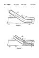
- FIG. 1An illustrative embodiment of a tubular graft connector 10 in accordance with this invention for connecting the end of a tubular graft to an aperture in the side wall of a patient's tubular body tissue structure is shown in FIG. 1.
- Connector 10includes a tubular first section 12 tubularly connected to a tubular second section 14.
- the longitudinal axis of second section 14extends transversely to the longitudinal axis of first section 12. It will be understood that "transverse” can mean perpendicular, but it can also mean acute or obtuse angles other than 90°.
- second section 14extends in both directions from the adjacent end of first section 12 so that connector 10 has the approximate shape of a capital letter T.
- the lumens through first and second sections 12 and 14communicate with one another inside the connector where the two sections meet.
- connector 10includes an open mesh framework 22 (e.g., a braid of nitinol, stainless steel, or tungsten wires or polymer strands) which may be covered with a rubber-like web 24 (e.g., of silicone).
- open mesh framework 22e.g., a braid of nitinol, stainless steel, or tungsten wires or polymer strands
- rubber-like web 24e.g., of silicone
- first section 12is of sufficient length that it actually forms an artificial graft structure. In other words, in this case first section 12 is integral with an artificial graft structure.
- section 12could be made shorter for tubular attachment to an initially separate artificial or natural graft.
- references herein to attachment of a connector to a graft structurewill be understood to be generic to both (1) integral formation of the connector and graft structure, and (2) initially separate formation and subsequent joining of the connector and graft structure.
- section 12may be attached to the graft structure by inserting it coaxially in an end portion of the graft structure. Section 12 may then resiliently expand to annularly engage the end portion of the graft structure. In addition, section 12 may be sutured to the graft structure.
- section 12may have radially outwardly projecting prongs (which may be hooked and/or barbed) to improve engagement and retention of the graft structure by section 12.
- section 12may be crimped around the outside of an axial end portion of the graft conduit as is described in more detail in connection with several later embodiments.
- Adhesivemay also be used in connections between the connectors of this invention and the associated tubular conduits. Additional information regarding various ones of these alternatives is provided in connection with other embodiments that are discussed below.
- the connector and graft conduitcan be connected to one another in advance and outside the patient's body. This eliminates space constraints for suturing inside the body, and in the coronary area it also eliminates the complexity of suturing to a beating heart.
- First and second sections 12 and 14may be joined to one another in any of a variety of ways. For example, these two sections may be sutured together, welded together, or formed integrally. Particularly preferred joining techniques are shown in later FIGS. and described below.
- connector structurese.g., a nitinol framework covered by a silicone web
- theyare extremely elastic and resilient. Thus they can be radically deformed (e.g., during installation), and they thereafter return to their original shape without any damage or memory that they were deformed.
- This type of structureis also flexible in use so that it may advantageously pulse in response to blood pressure pulses when it is used in a patient's circulatory system. In other words, the connector is compliant under blood pressure.
- FIG. 1shows part of illustrative apparatus 100 for installing a connector like connector 10 in a patient.
- the portion of apparatus 100 that is shown in FIG. 1comprises delivery tube or sleeve 110.
- FIGS. 2 and 3show progressive insertion of connector 10 into sleeve 110.
- one end portion of second section 14is inserted into sleeve 110 as shown in FIG. 2.
- first section 12is folded down along the other end portion of second section 14 so that the remainder of connector 10 can be pushed into sleeve 110 as shown in FIG. 3.
- FIGS. 4-8show apparatus 100 being used to install connector 10 through an aperture 34 in the side wall 32 of a patient's tubular body tissue structure 30 (e.g., a blood vessel).
- longitudinal guide structure 120e.g., a wire
- a dilator structure 130is advanced along and concentrically around guide structure 120 so that its distal, conically tapered, nose portion opens up aperture 34.
- the next stepis to advance the distal portion of sleeve 110 over dilator 130, through dilated aperture 34, and into the lumen of body conduit 30 as shown progressively in FIGS. 4 and 5.
- Dilator structure 130may then be withdrawn proximally as is also shown in FIG. 5 and ultimately removed from sleeve 110.
- a subsequent stepis shown in FIG. 6 and involves inserting connector 10 into and along sleeve 110 so that portions of connector 10 are disposed around guide structure 120.
- connector 10may be initially inserted into the proximal end of sleeve 110 as shown in FIGS. 1-3, but with the addition of guide structure 120 passing through first section 12 and the end portion of section 14 that first section 12 is not folded back along.
- Second section 14resiliently expands when released from sleeve 110 to approximately the same size as the interior of body conduit 30.
- second section 14resiliently and annularly bears on the inner surface of the side wall 32 of conduit 30. This helps to secure connector 10 in conduit 30.
- FIGS. 9-12Illustrative, especially preferred, techniques for producing connectors 10 of the type shown in the previously described FIGS. are shown in FIGS. 9-12.
- mesh framework strands 22one representative strand 22a being emphasized in FIG. 9 for purposes of illustration
- first section 12is formed first as shown in FIG. 10 with unbraided strands 22 of the connector framework left extending from one end of that first section.
- these initially unbraided strandsare used to weave or braid second section 14 around mandrel 210 as shown in FIG. 11.
- framework strands 22are unbroken and continuous between first and second sections 12 and 14 (as is apparent from considering representative strand 22a in FIG. 9).
- framework strandse.g., emphasized strands 22b and 22c
- second section 14is formed using framework strands 22 that are separate from the framework strands 22 that are used to form first section 12.
- the unbraided extensions of the first section strandsare woven into the second section framework to unite the two sections as shown in FIG. 12.
- FIG. 13shows just one example of possible use of connectors of the type shown in the previously described FIGS.
- connector 10is used to connect one end of a coronary bypass graft 220 to the coronary artery 30 of a patient downstream from a partial occlusion 36 of that artery.
- the other end of graft 220is connected to an aperture in the side wall of the patient's aorta 40 (see FIGS. 36-39 and the discussion of those FIGS. below for an example of a connector that can be used to connect graft conduit 220 to an aperture in the side wall of much larger aorta 40).
- Second section 14 of connector 10is disposed concentrically inside artery 30.
- First section 12 of connector 10extends out of an aperture in the side wall of artery 30 and is connected to or integral with graft 220. Accordingly, graft 220 and connector 10 cooperate to allow blood to flow from aorta 40 to artery 30 downstream from partial occlusion 36. This blood flow supplements the flow of blood through occlusion 36, thereby relieving the patient of the adverse effects of occlusion 36.
- FIG. 14shows an illustrative use of a connector 10' in accordance with this invention in a bypass around a total occlusion 36' in a patient's coronary artery 30.
- connector 10'is more nearly L-shaped.
- second section 14' of connector 10'extends transversely in only one direction from the adjacent end of first section 12'.
- second section 14extends from first section 12' in the downstream direction in coronary artery 30.
- the upstream end of second section 14'can be closed or substantially closed because no blood is coming from that direction due to the presence of total occlusion 36'.
- connector 10'can be inserted in artery 30 (or any other tubular body conduit) in substantially the same way that connector 10 is inserted (e.g., using apparatus of the type shown in FIGS. 1-8). The only difference is that in the case of connector 10', second section 14' extends in only one direction along conduit 30 from aperture 34.
- FIG. 14ashows an alternative installation of an L-shaped connector 10".
- connector 10"can be initially separate from or integral with graft vessel 220".
- the designmay utilize shape memory braid over a tapered and formed mandrel, and may be shaped to match the inner lumen size of the grafted vessel and tapered to transition from the aortic connection to the inner lumen dimension.
- the connectors and connector insertion apparatus of this inventionare suitable for use in conventional surgery and in less invasive patient treatment procedures such as percutaneous laparoscopy and intraluminal procedures of the kind described in the first three references mentioned above. If the target body conduit 30 has been exposed surgically, apparatus 100 can be made to approach the body conduit through the surgical opening. With regard to laparoscopic or intraluminal procedures, the connectors of this invention have (or can be folded to have) relatively small cross sections. Apparatus 100 can also have a small cross section. This allows the connector and associated apparatus 100 to be inserted into the patient via the relatively small passageways or instruments that are used for laparoscopy. Similarly, such small cross sections allow the connector and associated apparatus 100 to be inserted into the patient intraluminally.
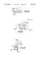
- FIG. 15shows another illustrative T-shaped connector 310 in accordance with the invention.
- Connector 310includes a first section 312 which is adapted to be received in an end of a tubular graft 320.
- Connector 310also includes a second section 314 which initially has a relatively small cross section as shown in FIG. 15, but which is circumferentially enlargeable to a relatively large cross section as shown in FIGS. 16 and 17.
- second section 314may be a modified (e.g., perforated) metal tube which is circumferentially expandable by a selectively inflatable balloon inside that section.
- Connector 310is typically inserted into a patient's tubular body conduit 30 with second section 314 in its relatively small cross-sectional configuration.
- second section 314is circumferentially expanded so that it annularly engages the inner surface of the side wall 32 of the conduit 30.
- Graft conduit 320(which, as in other embodiments, may be artificial conduit, natural conduit, or a combination of both) may be attached to first section 312 before or after second section 314 is inserted in conduit 30.
- An annular external seal 350(FIG. 17) can be applied over the connector around aperture 34 to provide a hemodynamic seal and to promote in-growth of tissue to further reinforce vessel connection over time. Examples of materials suitable for use in making seal 350 are silicone and urethane.
- Connector 410includes a first section 412 that may be a tubular framework.
- Connector 410also includes a second section 414 that comprises spring coils that extend transversely from an end portion of first section 412.
- Sections 412 and 414may made of shape memory materials similar to those mentioned above for the framework of sections 12 and 14 in FIG. 1.
- Second section 414is axially compressible as shown in FIG. 19 to facilitate insertion of the second section through an aperture 34 in a side wall of a patient's tubular body conduit 30. After second section 414 has been inserted through aperture 34 in the axially compressed condition shown in FIG.
- Graft conduit 420may be artificial, natural, or both, and may be attached to first section 412 (e.g., by suturing) at any convenient time either before or after insertion of second section 414 in conduit 30.
- First section 412may be inserted into an axial end portion of graft conduit 420 and allowed to resiliently expand into annular engagement with that end portion.
- first section 412may be crimped around the outside of the end portion of graft conduit 420. Protrusions from first section 412 may penetrate the end portion of conduit 420 to more securely attach these two structures.
- an annular seal 450(similar to above-described seal 350) may be placed around the outside of the joint between graft 420 and conduit 30 as shown in FIGS. 21 and 22 for purposes similar to those described above for seal 350.
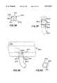
- section 514can be used for second section 414, one example being shown at 514 in FIGS. 23-25.
- Illustrative constructions of section 514include a resilient, axially compressible spring braid or a self-expanding nitinol tube.
- the second sectionis axially compressed as shown in FIG. 23 to facilitate insertion of the second section through aperture 34 in the side wall of body conduit 30. After second section 514 is through aperture 34, the axial compression of the second section is released so that it springs out along the lumen of conduit 30 as shown in FIGS. 24 and 25.
- Section 514may have a rubber-like (e.g., silicone) outer cover to prevent leakage via aperture 34 around first section 512.
- FIG. 25illustrates another possible constructional feature of the connectors of this invention.
- Thisis a circumferentially crimpable first section 512 (e.g., of nitinol or stainless steel).
- crimpable first section 512has an initially relatively large circumference into which an end of tubular graft 520 can be inserted.
- First section 512is then circumferentially crimped to reduce its circumference and cause it to annularly engage the outside of graft conduit 520.
- first section 512may have radially inwardly extending prongs 560 (e.g., of nitinol or stainless steel) to penetrate or at least deform the material of graft conduit 520 and thereby help to retain the graft conduit in the first section.
- Prongs 560may be hooked (i.e., curved) and/or barbed (somewhat like fishhooks) to still further strengthen the connection between graft conduit 520 and connector 510.
- Adhesivemay also be used to further secure the connector to graft conduit 520. It may be advantageous to secure the connector to the outside of the graft conduit in this general way because it reduces possible obstruction of fluid flow in the graft conduit due to the presence of the connector. In the case of natural graft conduits, securing the connector to the outside of that conduit helps protect the delicate internal lumen of the conduit.
- a crimpable connector sectionmay be made of a crimpable material or some other crimpable structure.
- a split and overlapping ring structuremay be used as shown in FIG. 39 and described in more detail below.
- the first section of a connectorcan have an oval cross section if desired. This may be useful, for example, when it is necessary to connect an end of a relatively large graft conduit to the side wall of a somewhat smaller conduit 30.
- FIG. 29shows an example of an oval crimp-type connector or connector portion 612. As in the embodiments illustrated by FIGS. 25-28, connector portion 612 is crimped around the outside of graft conduit 620 and has radially inwardly extending prongs 660 for penetrating the material of the graft conduit to more securely engage that conduit.
- FIGS. 30-32show application of certain of the principles of this invention to end-to-end connectors.
- connector 710is to be used to connect an end of vessel 730a to an end of vessel 730b.
- one of these vesselsmay be a tubular graft conduit.
- Connector 710includes two axially aligned tubular end sections 712a and 712b joined by an intermediate tubular seal section 750.
- Each of end sections 712is circumferentially crimpable to annularly engage the outer surface of the end of a respective one of vessels 730 which has been inserted in that end section (see FIG. 32).
- Prongs 760extend radially inwardly from each of end sections 712 as shown in FIG. 31 to better hold the associated vessel in that end section.
- Seal section 750e.g., of silicone or urethane
- FIGS. 33-35An alternative embodiment of an end-to-end connector 810 is shown in FIGS. 33-35.
- Connector 810is similar to connector 710, except that seal section 850 (again, e.g., of silicone or urethane) is axially compressible.
- seal section 850(again, e.g., of silicone or urethane) is axially compressible.
- Connector 910is shown by itself prior to crimping and installation in FIG. 36.
- Connector 910includes crimpable tubular section 912 which has resilient struts 970 (e.g., of nitinol wire) that extend radially out from both of its axial ends.
- Connector 910illustrates an alternative crimpable structure in which section 912 is an axially slit tube with the slit edge portions radially overlapping one another (see also FIG. 39). This structure is crimped to reduce its initially relatively large circumference by increasing the amount of overlap of the slit edge portions. This principle is applicable to any of the crimpable connector structures shown and described herein.
- conduit 920may be a graft conduit which is to be connected to a patient's body conduit 930.
- Prongs 960extend into the side wall of conduit 920 as in related previously described embodiments.
- Struts 970are deflected substantially parallel to the longitudinal axis of conduit 920. This may be done, for example, by surrounding the structure shown in FIG. 37 with a delivery tube (not shown). In the condition shown in FIG.
- connector 910is installed in aperture 934 and struts 970 are released so that they can resiliently spring out and resume their initial positions as shown in FIGS. 38 and 39.
- struts 970bear on both the inner and outer surfaces of conduit side wall 932. Struts 970 thereby hold connector 910 and conduit 920 in the position required to connect conduit 920 to conduit 930.
- Connectors of the type shown in FIGS. 36-39are particularly suitable for connecting an end of a relatively small conduit 920 to the side wall of a relatively large conduit 930.
- a connector of this typecan be used in FIGS. 13-14a to connect the upstream end of graft conduit 220 or 220" to aorta 40.
- FIGS. 40 and 41show another illustrative embodiment of an L-shaped connector 1010 in accordance with this invention.
- Connector 1010may be braided or coiled strands of nitinol, stainless steel, tungsten, or polymer, or nitinol tubing, as in other previously described embodiments.
- Connector 1010includes a first section 1012 which may be crimpable around an end portion of tabular conduit 1020 as in related previously described embodiments. Alternatively or in addition, first section 1012 may include hooks and/or barbs for connection to conduit 1020.
- Second section 1014extends transversely from first section 1012 in only one direction and is configured to extend along the lumen inside another tubular conduit (not shown).
- the second sectionmay have a plurality of radially outwardly extending prongs 1080 (e.g., of nitinol wire) that deform or penetrate the side wall of the conduit in which the second section is disposed.
- Prongs 1080may be curved and/or barbed somewhat like fishing hooks to help them even more securely hold onto the tissue that they engage.
- Either or both sections 1012 and 1014 of connector 1010may be balloon-expanded to help anchor that section to the associated conduit
- FIGS. 42 and 43show another illustrative embodiment of a T-shaped connector 1110 which can be somewhat like the embodiment shown in FIGS. 15-17.
- the principal difference between this embodiment and the FIGS. 15-17 embodimentis that in connector 1110 the second section 1114 of the connector extends only part of the way around the inside of body conduit 30. This reduces the amount of connector material that is in contact with the interior surface of conduit 30. Reducing the circumferential extent of second section 1114 in this way may also facilitate delivery and installation of the connector. Second section 1114 may be perforated to facilitate changes of shape of that section for deployment of the connector.
- Graft conduit 1120may be attached to first section 1112 in any suitable way (e.g., as described above in connection with other embodiments).
Landscapes
- Health & Medical Sciences (AREA)
- Life Sciences & Earth Sciences (AREA)
- Veterinary Medicine (AREA)
- Public Health (AREA)
- General Health & Medical Sciences (AREA)
- Animal Behavior & Ethology (AREA)
- Engineering & Computer Science (AREA)
- Biomedical Technology (AREA)
- Heart & Thoracic Surgery (AREA)
- Transplantation (AREA)
- Vascular Medicine (AREA)
- Oral & Maxillofacial Surgery (AREA)
- Cardiology (AREA)
- Pulmonology (AREA)
- Gastroenterology & Hepatology (AREA)
- Surgery (AREA)
- Nuclear Medicine, Radiotherapy & Molecular Imaging (AREA)
- Medical Informatics (AREA)
- Molecular Biology (AREA)
- Prostheses (AREA)
Abstract
Description
Claims (6)
Priority Applications (6)
| Application Number | Priority Date | Filing Date | Title |
|---|---|---|---|
| US08/958,937US5972017A (en) | 1997-04-23 | 1997-10-28 | Method of installing tubular medical graft connectors |
| AU51625/98AAU5162598A (en) | 1996-11-07 | 1997-11-05 | Tubular medical graft connectors |
| PCT/US1997/019947WO1998019630A2 (en) | 1996-11-07 | 1997-11-05 | Tubular medical graft connectors |
| US09/293,254US6152945A (en) | 1997-04-23 | 1999-04-16 | Tubular medical graft connectors |
| US09/539,643US6293965B1 (en) | 1997-04-23 | 2000-03-30 | Tubular medical graft connectors |
| US09/921,048US6451033B1 (en) | 1997-04-23 | 2001-08-02 | Tubular medical graft connectors |
Applications Claiming Priority (2)
| Application Number | Priority Date | Filing Date | Title |
|---|---|---|---|
| US08/839,199US6036702A (en) | 1997-04-23 | 1997-04-23 | Medical grafting connectors and fasteners |
| US08/958,937US5972017A (en) | 1997-04-23 | 1997-10-28 | Method of installing tubular medical graft connectors |
Related Parent Applications (1)
| Application Number | Title | Priority Date | Filing Date |
|---|---|---|---|
| US08/839,199Continuation-In-PartUS6036702A (en) | 1996-11-07 | 1997-04-23 | Medical grafting connectors and fasteners |
Related Child Applications (1)
| Application Number | Title | Priority Date | Filing Date |
|---|---|---|---|
| US09/293,254DivisionUS6152945A (en) | 1997-04-23 | 1999-04-16 | Tubular medical graft connectors |
Publications (1)
| Publication Number | Publication Date |
|---|---|
| US5972017Atrue US5972017A (en) | 1999-10-26 |
Family
ID=27126092
Family Applications (4)
| Application Number | Title | Priority Date | Filing Date |
|---|---|---|---|
| US08/958,937Expired - LifetimeUS5972017A (en) | 1996-11-07 | 1997-10-28 | Method of installing tubular medical graft connectors |
| US09/293,254Expired - LifetimeUS6152945A (en) | 1997-04-23 | 1999-04-16 | Tubular medical graft connectors |
| US09/539,643Expired - Fee RelatedUS6293965B1 (en) | 1997-04-23 | 2000-03-30 | Tubular medical graft connectors |
| US09/921,048Expired - Fee RelatedUS6451033B1 (en) | 1997-04-23 | 2001-08-02 | Tubular medical graft connectors |
Family Applications After (3)
| Application Number | Title | Priority Date | Filing Date |
|---|---|---|---|
| US09/293,254Expired - LifetimeUS6152945A (en) | 1997-04-23 | 1999-04-16 | Tubular medical graft connectors |
| US09/539,643Expired - Fee RelatedUS6293965B1 (en) | 1997-04-23 | 2000-03-30 | Tubular medical graft connectors |
| US09/921,048Expired - Fee RelatedUS6451033B1 (en) | 1997-04-23 | 2001-08-02 | Tubular medical graft connectors |
Country Status (1)
| Country | Link |
|---|---|
| US (4) | US5972017A (en) |
Cited By (169)
| Publication number | Priority date | Publication date | Assignee | Title |
|---|---|---|---|---|
| US6117156A (en)* | 1996-05-03 | 2000-09-12 | Medinol Ltd. | Bifurcated stent and method of making same |
| WO2000057817A1 (en)* | 1999-03-26 | 2000-10-05 | Scimed Life Systems, Inc. | An implantable bypass device |
| US6149681A (en)* | 1996-09-20 | 2000-11-21 | Converge Medical, Inc. | Radially expanding prostheses and systems for their deployment |
| US6217585B1 (en) | 1996-08-16 | 2001-04-17 | Converge Medical, Inc. | Mechanical stent and graft delivery system |
| US6221098B1 (en) | 1997-08-13 | 2001-04-24 | Advanced Cardiovascular Systems, Inc. | Stent and catheter assembly and method for treating bifurcations |
| US6235054B1 (en) | 1998-02-27 | 2001-05-22 | St. Jude Medical Cardiovascular Group, Inc. | Grafts with suture connectors |
| US20010001826A1 (en)* | 1998-01-23 | 2001-05-24 | Heartport, Inc. | System for performing vascular anastomoses |
| US20010001827A1 (en)* | 1998-03-09 | 2001-05-24 | Chapman Troy J. | Anastomosis device and method |
| US6251133B1 (en) | 1996-05-03 | 2001-06-26 | Medinol Ltd. | Bifurcated stent with improved side branch aperture and method of making same |
| US6254593B1 (en) | 1999-12-10 | 2001-07-03 | Advanced Cardiovascular Systems, Inc. | Bifurcated stent delivery system having retractable sheath |
| US6293955B1 (en) | 1996-09-20 | 2001-09-25 | Converge Medical, Inc. | Percutaneous bypass graft and securing system |
| US6361544B1 (en) | 1997-08-13 | 2002-03-26 | Advanced Cardiovascular Systems, Inc. | Stent and catheter assembly and method for treating bifurcations |
| US6361559B1 (en) | 1998-06-10 | 2002-03-26 | Converge Medical, Inc. | Thermal securing anastomosis systems |
| US6361555B1 (en) | 1999-12-15 | 2002-03-26 | Advanced Cardiovascular Systems, Inc. | Stent and stent delivery assembly and method of use |
| US6379319B1 (en) | 1996-10-11 | 2002-04-30 | Transvascular, Inc. | Systems and methods for directing and snaring guidewires |
| US6383213B2 (en) | 1999-10-05 | 2002-05-07 | Advanced Cardiovascular Systems, Inc. | Stent and catheter assembly and method for treating bifurcations |
| US6387120B2 (en) | 1999-12-09 | 2002-05-14 | Advanced Cardiovascular Systems, Inc. | Stent and catheter assembly and method for treating bifurcations |
| US6398807B1 (en)* | 2000-01-31 | 2002-06-04 | Scimed Life Systems, Inc. | Braided branching stent, method for treating a lumen therewith, and process for manufacture therefor |
| US6402767B1 (en) | 1997-05-22 | 2002-06-11 | Kensey Nash Corporation | Anastomosis connection system and method of use |
| US6440163B1 (en)* | 1998-11-06 | 2002-08-27 | St. Jude Medical Atg, Inc. | Medical anastomosis apparatus |
| US20020120325A1 (en)* | 1996-05-03 | 2002-08-29 | Jacob Richter | Method of making a bifurcated stent with improved side branch aperture |
| FR2822370A1 (en)* | 2001-03-23 | 2002-09-27 | Perouse Lab | TUBULAR ENDOPROSTHESIS COMPRISING A DEFORMABLE RING AND NECESSARY INTERVENTION FOR ITS IMPLANTATION |
| US20020173809A1 (en)* | 1999-09-01 | 2002-11-21 | Fleischman Sidney D. | Sutureless anastomosis system deployment concepts |
| US6485496B1 (en) | 1997-10-24 | 2002-11-26 | Wilhelmus Joseph Leonardus Suyker | Mechanical anastomosis system for hollow structures |
| US6494889B1 (en) | 1999-09-01 | 2002-12-17 | Converge Medical, Inc. | Additional sutureless anastomosis embodiments |
| US6494875B1 (en) | 1998-08-24 | 2002-12-17 | Advanced Cardiovascular Systems, Inc. | Bifurcated catheter assembly |
| US20030014062A1 (en)* | 1996-11-08 | 2003-01-16 | Houser Russell A. | Percutaneous bypass graft and securing system |
| US6508252B1 (en) | 1998-11-06 | 2003-01-21 | St. Jude Medical Atg, Inc. | Medical grafting methods and apparatus |
| US20030023252A1 (en)* | 2001-07-05 | 2003-01-30 | Whayne James G. | Distal anastomosis system |
| US6517558B2 (en) | 1999-01-15 | 2003-02-11 | Ventrica, Inc. | Methods and devices for forming vascular anastomoses |
| US6544219B2 (en) | 2000-12-15 | 2003-04-08 | Advanced Cardiovascular Systems, Inc. | Catheter for placement of therapeutic devices at the ostium of a bifurcation of a body lumen |
| WO2002030329A3 (en)* | 2000-10-13 | 2003-04-24 | Rex Medical Lp | Covered stents with side branch |
| US20030093095A1 (en)* | 2001-07-05 | 2003-05-15 | Whayne James G. | Distal anastomosis system |
| US6582394B1 (en) | 2000-11-14 | 2003-06-24 | Advanced Cardiovascular Systems, Inc. | Stent and catheter assembly and method for treating bifurcated vessels |
| US6596003B1 (en) | 2000-06-28 | 2003-07-22 | Genzyme Corporation | Vascular anastomosis device |
| US20030167064A1 (en)* | 1999-09-01 | 2003-09-04 | Whayne James G. | Advanced anastomosis systems (II) |
| US6622604B1 (en) | 2000-01-31 | 2003-09-23 | Scimed Life Systems, Inc. | Process for manufacturing a braided bifurcated stent |
| US6635214B2 (en) | 1999-09-10 | 2003-10-21 | Ventrica, Inc. | Manufacturing conduits for use in placing a target vessel in fluid communication with a source of blood |
| US20030204198A1 (en)* | 1998-01-28 | 2003-10-30 | St. Jude Medical Atg, Inc. | Vessel cutting devices |
| US6652571B1 (en)* | 2000-01-31 | 2003-11-25 | Scimed Life Systems, Inc. | Braided, branched, implantable device and processes for manufacture thereof |
| US20030225425A1 (en)* | 2002-06-03 | 2003-12-04 | David Kupiecki | Devices and methods for interconnecting vessels |
| US20030229365A1 (en)* | 2002-06-10 | 2003-12-11 | Whayne James G. | Angled vascular anastomosis system |
| US6673107B1 (en) | 1999-12-06 | 2004-01-06 | Advanced Cardiovascular Systems, Inc. | Bifurcated stent and method of making |
| US6685738B2 (en) | 2000-01-31 | 2004-02-03 | Scimed Life Systems, Inc. | Braided endoluminal device having tapered filaments |
| US6695877B2 (en) | 2001-02-26 | 2004-02-24 | Scimed Life Systems | Bifurcated stent |
| US6699256B1 (en) | 1999-06-04 | 2004-03-02 | St. Jude Medical Atg, Inc. | Medical grafting apparatus and methods |
| US6702833B1 (en)* | 1998-09-21 | 2004-03-09 | Andreas Gussmann | Prosthetic tube connection |
| US6702829B2 (en) | 1997-04-23 | 2004-03-09 | St. Jude Medical Atg, Inc. | Medical grafting connectors and fasteners |
| US6709440B2 (en) | 2001-05-17 | 2004-03-23 | Advanced Cardiovascular Systems, Inc. | Stent and catheter assembly and method for treating bifurcations |
| US20040068278A1 (en)* | 1999-12-06 | 2004-04-08 | Converge Medical Inc. | Anastomosis systems |
| US20040082850A1 (en)* | 2002-10-23 | 2004-04-29 | Medtonic, Inc. | Methods and apparatus for locating body vessels and occlusions in body vessels |
| US20040092858A1 (en)* | 2002-08-28 | 2004-05-13 | Heart Leaflet Technologies, Inc. | Leaflet valve |
| US20040106989A1 (en)* | 2002-07-03 | 2004-06-03 | Wilson Robert F. | Leaflet reinforcement for regurgitant valves |
| US20040113306A1 (en)* | 1999-05-19 | 2004-06-17 | Rapacki Alan R | Manufacturing conduits for use in placing a target vessel in fluid communication with a source of blood |
| US20040117860A1 (en)* | 2002-09-19 | 2004-06-17 | Lg Electronics Inc. | Multicast service providing method in mobile communication system |
| US20040138685A1 (en)* | 2003-01-14 | 2004-07-15 | Clague Cynthia T. | Methods and apparatus for making precise incisions in body vessels |
| US6770092B2 (en) | 1996-05-03 | 2004-08-03 | Medinol Ltd. | Method of delivering a bifurcated stent |
| US20040172050A1 (en)* | 1995-02-24 | 2004-09-02 | Bolduc Lee R. | Surgical clips and methods for tissue approximation |
| US20040199177A1 (en)* | 1996-06-14 | 2004-10-07 | Ducksoo Kim | Catheter apparatus having an improved shape-memory alloy cuff and inflatable on-demand balloon for creating a bypass graft in-vivo |
| US20050033277A1 (en)* | 2002-10-23 | 2005-02-10 | Clague Cynthia T. | Electrosurgical methods and apparatus for making precise incisions in body vessels |
| US6858035B2 (en) | 2001-07-05 | 2005-02-22 | Converge Medical, Inc. | Distal anastomosis system |
| US20050080439A1 (en)* | 2000-04-29 | 2005-04-14 | Carson Dean F. | Devices and methods for forming magnetic anastomoses and ports in vessels |
| US6896687B2 (en) | 1997-05-19 | 2005-05-24 | Pepi Dakov | Connectors for hollow anatomical structures and methods of use |
| US6899718B2 (en) | 1995-02-24 | 2005-05-31 | Heartport, Inc. | Devices and methods for performing avascular anastomosis |
| US20050149073A1 (en)* | 2003-12-17 | 2005-07-07 | Arani Djavad T. | Mechanisms and methods used in the anastomosis of biological conduits |
| US20050165427A1 (en)* | 2004-01-22 | 2005-07-28 | Jahns Scott E. | Vessel sealing devices |
| US20050245946A1 (en)* | 1997-09-04 | 2005-11-03 | Nash John E | Surgical connector systems and methods of use |
| US20050251244A1 (en)* | 1997-09-23 | 2005-11-10 | Design & Performance - Cyprus Limited | Non-thrombogenic stent jacket |
| US20050251163A1 (en)* | 2001-07-05 | 2005-11-10 | Converge Medical, Inc. | Vascular anastomosis systems |
| US7025773B2 (en)* | 1999-01-15 | 2006-04-11 | Medtronic, Inc. | Methods and devices for placing a conduit in fluid communication with a target vessel |
| US20060085061A1 (en)* | 1996-11-04 | 2006-04-20 | Vardi Gil M | Extendible stent apparatus and method for deploying the same |
| US20060116748A1 (en)* | 2003-04-14 | 2006-06-01 | Aaron Kaplan | Stepped balloon catheter for treating vascular bifurcations |
| US7090694B1 (en) | 2003-11-19 | 2006-08-15 | Advanced Cardiovascular Systems, Inc. | Portal design for stent for treating bifurcated vessels |
| US7122044B2 (en) | 1994-06-17 | 2006-10-17 | Heartport, Inc. | Surgical stapling instrument and method thereof |
| US20060241740A1 (en)* | 1996-11-04 | 2006-10-26 | Advanced Stent Technologies, Inc. | Extendible stent apparatus |
| US20060247756A1 (en)* | 1996-05-03 | 2006-11-02 | Jacob Richter | System and method for delivering a bifurcated stent |
| US7141060B1 (en)* | 2000-01-20 | 2006-11-28 | Katharina Metz | Instrument for inserting a prosthesis tube connection |
| US7175644B2 (en) | 2001-02-14 | 2007-02-13 | Broncus Technologies, Inc. | Devices and methods for maintaining collateral channels in tissue |
| US7220275B2 (en) | 1996-11-04 | 2007-05-22 | Advanced Stent Technologies, Inc. | Stent with protruding branch portion for bifurcated vessels |
| US20070168020A1 (en)* | 2001-02-26 | 2007-07-19 | Brucker Gregory G | Bifurcated stent and delivery system |
| US20070208415A1 (en)* | 2006-03-06 | 2007-09-06 | Kevin Grotheim | Bifurcated stent with controlled drug delivery |
| US20070265698A1 (en)* | 2003-07-31 | 2007-11-15 | Advanced Cardiovascular Systems, Inc. | Intravascular stent with inverted end rings |
| US20080015678A1 (en)* | 2004-10-13 | 2008-01-17 | Tryton Medical, Inc. | Prosthesis for placement at a luminal os |
| US7341598B2 (en) | 1999-01-13 | 2008-03-11 | Boston Scientific Scimed, Inc. | Stent with protruding branch portion for bifurcated vessels |
| US20080086197A1 (en)* | 2006-10-10 | 2008-04-10 | Boston Scientific Scimed, Inc. | Bifurcated Stent with Entire Circumferential Petal |
| US20080143759A1 (en)* | 2006-12-14 | 2008-06-19 | Au Optronics Corporation | Gate Driving Circuit and Driving Circuit Unit Thereof |
| US20080172123A1 (en)* | 2007-01-16 | 2008-07-17 | Boston Scientific Scimed, Inc. | Bifurcated stent |
| US7422563B2 (en) | 1999-08-05 | 2008-09-09 | Broncus Technologies, Inc. | Multifunctional tip catheter for applying energy to tissue and detecting the presence of blood flow |
| US7462162B2 (en) | 2001-09-04 | 2008-12-09 | Broncus Technologies, Inc. | Antiproliferative devices for maintaining patency of surgically created channels in a body organ |
| US20090069881A1 (en)* | 2007-09-12 | 2009-03-12 | Boston Scientific Scimed, Inc. | Bifurcated Stent with Open Ended Side Branch Support |
| US7537609B2 (en) | 1998-01-14 | 2009-05-26 | Boston Scientific Scimed, Inc. | Extendible stent apparatus |
| WO2009065917A1 (en) | 2007-11-23 | 2009-05-28 | Assistance Publique Des Hopitaux De Marseille | Device for implanting a vascular prosthesis |
| US7540881B2 (en) | 2005-12-22 | 2009-06-02 | Boston Scientific Scimed, Inc. | Bifurcation stent pattern |
| US20090163993A1 (en)* | 2007-12-21 | 2009-06-25 | Boston Scientific Scimed, Inc. | Bi-Stable Bifurcated Stent Petal Geometry |
| US7578841B2 (en) | 2001-09-24 | 2009-08-25 | Boston Scientific Scimed, Inc. | Stent with protruding branch portion for bifurcated vessels |
| US7578828B2 (en) | 1999-01-15 | 2009-08-25 | Medtronic, Inc. | Methods and devices for placing a conduit in fluid communication with a target vessel |
| US20090240318A1 (en)* | 2008-03-19 | 2009-09-24 | Boston Scientific Scimed, Inc. | Stent expansion column, strut and connector slit design |
| US20090299460A1 (en)* | 2008-05-29 | 2009-12-03 | Boston Scientific Scimed, Inc. | Bifurcated Stent and Delivery System |
| US7678142B2 (en) | 1996-11-04 | 2010-03-16 | Boston Scientific Scimed, Inc. | Extendible stent apparatus |
| US7708712B2 (en) | 2001-09-04 | 2010-05-04 | Broncus Technologies, Inc. | Methods and devices for maintaining patency of surgically created channels in a body organ |
| US20100130995A1 (en)* | 2008-11-26 | 2010-05-27 | Phraxis Inc. | Anastomotic connector |
| US7731741B2 (en) | 2005-09-08 | 2010-06-08 | Boston Scientific Scimed, Inc. | Inflatable bifurcation stent |
| US20100160939A1 (en)* | 2008-12-19 | 2010-06-24 | St. Jude Medical, Inc. | Systems, apparatuses, and methods for cardiovascular cutting devices and valves |
| US7799064B2 (en) | 2001-02-26 | 2010-09-21 | Boston Scientific Scimed, Inc. | Bifurcated stent and delivery system |
| US7815590B2 (en) | 1999-08-05 | 2010-10-19 | Broncus Technologies, Inc. | Devices for maintaining patency of surgically created channels in tissue |
| US7833266B2 (en) | 2007-11-28 | 2010-11-16 | Boston Scientific Scimed, Inc. | Bifurcated stent with drug wells for specific ostial, carina, and side branch treatment |
| US7833264B2 (en) | 2006-03-06 | 2010-11-16 | Boston Scientific Scimed, Inc. | Bifurcated stent |
| US7842082B2 (en) | 2006-11-16 | 2010-11-30 | Boston Scientific Scimed, Inc. | Bifurcated stent |
| US7842081B2 (en) | 2005-11-14 | 2010-11-30 | Boston Scientific Scimed, Inc. | Stent with spiral side-branch |
| US7922758B2 (en) | 2006-06-23 | 2011-04-12 | Boston Scientific Scimed, Inc. | Nesting twisting hinge points in a bifurcated petal geometry |
| US7938840B2 (en) | 1999-04-05 | 2011-05-10 | Medtronic, Inc. | Apparatus and methods for anastomosis |
| US20110130823A1 (en)* | 2009-11-30 | 2011-06-02 | Biotronik Vi Patent Ag | Stent having function elements |
| US7959667B2 (en) | 2006-07-07 | 2011-06-14 | Abbott Cardiovascular Systems Inc. | Catheter assembly and method for treating bifurcations |
| US7972372B2 (en)* | 2003-04-14 | 2011-07-05 | Tryton Medical, Inc. | Kit for treating vascular bifurcations |
| US7993356B2 (en) | 1998-02-13 | 2011-08-09 | Medtronic, Inc. | Delivering a conduit into a heart wall to place a coronary vessel in communication with a heart chamber and removing tissue from the vessel or heart wall to facilitate such communication |
| US8002740B2 (en) | 2003-07-18 | 2011-08-23 | Broncus Technologies, Inc. | Devices for maintaining patency of surgically created channels in tissue |
| US8007528B2 (en) | 2004-03-17 | 2011-08-30 | Boston Scientific Scimed, Inc. | Bifurcated stent |
| US8038706B2 (en) | 2005-09-08 | 2011-10-18 | Boston Scientific Scimed, Inc. | Crown stent assembly |
| US8043366B2 (en) | 2005-09-08 | 2011-10-25 | Boston Scientific Scimed, Inc. | Overlapping stent |
| US8083791B2 (en) | 2003-04-14 | 2011-12-27 | Tryton Medical, Inc. | Method of treating a lumenal bifurcation |
| US8118861B2 (en) | 2007-03-28 | 2012-02-21 | Boston Scientific Scimed, Inc. | Bifurcation stent and balloon assemblies |
| US20120123198A1 (en)* | 2010-11-16 | 2012-05-17 | Marcotte Amy L | Port with conduit wraparound feature |
| US8206429B2 (en) | 2006-11-02 | 2012-06-26 | Boston Scientific Scimed, Inc. | Adjustable bifurcation catheter incorporating electroactive polymer and methods of making and using the same |
| US8216267B2 (en) | 2006-09-12 | 2012-07-10 | Boston Scientific Scimed, Inc. | Multilayer balloon for bifurcated stent delivery and methods of making and using the same |
| US8257432B2 (en) | 2003-04-14 | 2012-09-04 | Tryton Medical, Inc. | Vascular bifurcation prosthesis with at least one frond |
| US8257425B2 (en) | 1999-01-13 | 2012-09-04 | Boston Scientific Scimed, Inc. | Stent with protruding branch portion for bifurcated vessels |
| US8298280B2 (en) | 2003-08-21 | 2012-10-30 | Boston Scientific Scimed, Inc. | Stent with protruding branch portion for bifurcated vessels |
| US8298278B2 (en) | 2006-03-07 | 2012-10-30 | Boston Scientific Scimed, Inc. | Bifurcated stent with improvement securement |
| US8308682B2 (en) | 2003-07-18 | 2012-11-13 | Broncus Medical Inc. | Devices for maintaining patency of surgically created channels in tissue |
| US8317855B2 (en) | 2005-05-26 | 2012-11-27 | Boston Scientific Scimed, Inc. | Crimpable and expandable side branch cell |
| US8343211B2 (en) | 2005-12-14 | 2013-01-01 | Boston Scientific Scimed, Inc. | Connectors for bifurcated stent |
| US8361092B1 (en) | 2007-06-18 | 2013-01-29 | Wilson T. Asfora | Vascular anastomosis device and method |
| US8366763B2 (en) | 2009-07-02 | 2013-02-05 | Tryton Medical, Inc. | Ostium support for treating vascular bifurcations |
| US8409167B2 (en) | 2004-07-19 | 2013-04-02 | Broncus Medical Inc | Devices for delivering substances through an extra-anatomic opening created in an airway |
| US8414635B2 (en) | 1999-02-01 | 2013-04-09 | Idev Technologies, Inc. | Plain woven stents |
| US8419788B2 (en) | 2006-10-22 | 2013-04-16 | Idev Technologies, Inc. | Secured strand end devices |
| US8435284B2 (en) | 2005-12-14 | 2013-05-07 | Boston Scientific Scimed, Inc. | Telescoping bifurcated stent |
| US8480728B2 (en) | 2005-05-26 | 2013-07-09 | Boston Scientific Scimed, Inc. | Stent side branch deployment initiation geometry |
| US8512360B2 (en) | 1998-02-13 | 2013-08-20 | Medtronic, Inc. | Conduits for use in placing a target vessel in fluid communication with source of blood |
| US8529618B2 (en) | 2003-04-14 | 2013-09-10 | Tryton Medical, Inc. | Ostium support for treating vascular bifurcations |
| US20130253549A1 (en)* | 2008-07-09 | 2013-09-26 | Covidien Lp | Methods and devices for sheath compression |
| US8647376B2 (en) | 2007-03-30 | 2014-02-11 | Boston Scientific Scimed, Inc. | Balloon fold design for deployment of bifurcated stent petal architecture |
| US8709034B2 (en) | 2011-05-13 | 2014-04-29 | Broncus Medical Inc. | Methods and devices for diagnosing, monitoring, or treating medical conditions through an opening through an airway wall |
| US8728012B2 (en) | 2008-12-19 | 2014-05-20 | St. Jude Medical, Inc. | Apparatus and method for measuring blood vessels |
| US8747456B2 (en) | 2007-12-31 | 2014-06-10 | Boston Scientific Scimed, Inc. | Bifurcation stent delivery system and methods |
| US8781604B2 (en) | 2004-08-18 | 2014-07-15 | Cardiac Pacemakers, Inc. | Method of implanting stimulation lead with biased curved section through the interatrial septum |
| EP2781204A1 (en)* | 2013-03-19 | 2014-09-24 | BALTON Spolka z ograniczona odpowiedzialnoscia | Intravascular system for introducing and fastening an autogenous vascular prosthesis |
| US8876881B2 (en) | 2006-10-22 | 2014-11-04 | Idev Technologies, Inc. | Devices for stent advancement |
| US8905961B2 (en) | 2008-12-19 | 2014-12-09 | St. Jude Medical, Inc. | Systems, apparatuses, and methods for cardiovascular conduits and connectors |
| US9023095B2 (en) | 2010-05-27 | 2015-05-05 | Idev Technologies, Inc. | Stent delivery system with pusher assembly |
| US9308311B2 (en) | 2011-06-15 | 2016-04-12 | Phraxis, Inc. | Arterial venous spool anchor |
| US9345532B2 (en) | 2011-05-13 | 2016-05-24 | Broncus Medical Inc. | Methods and devices for ablation of tissue |
| US9427340B2 (en) | 2004-12-14 | 2016-08-30 | Boston Scientific Scimed, Inc. | Stent with protruding branch portion for bifurcated vessels |
| US9566146B2 (en) | 2008-12-19 | 2017-02-14 | St. Jude Medical, Inc. | Cardiovascular valve and valve housing apparatuses and systems |
| US9707108B2 (en) | 2010-11-24 | 2017-07-18 | Tryton Medical, Inc. | Support for treating vascular bifurcations |
| US20170273809A1 (en)* | 2014-12-18 | 2017-09-28 | Endospan Ltd. | Endovascular stent-graft with fatigue-resistant lateral tube |
| US10004507B2 (en) | 2007-06-18 | 2018-06-26 | Asfora Ip, Llc | Vascular anastomosis device and method |
| US10206681B2 (en) | 2007-06-18 | 2019-02-19 | Asfora Ip, Llc | Vascular anastomosis device and method |
| US10272260B2 (en) | 2011-11-23 | 2019-04-30 | Broncus Medical Inc. | Methods and devices for diagnosing, monitoring, or treating medical conditions through an opening through an airway wall |
| US10456239B2 (en) | 2011-06-15 | 2019-10-29 | Phraxis Inc. | Anastomotic connector and system for delivery |
| US10500077B2 (en) | 2012-04-26 | 2019-12-10 | Poseidon Medical Inc. | Support for treating vascular bifurcations |
| US10786346B2 (en) | 2012-06-15 | 2020-09-29 | Phraxis Inc. | Arterial anchor devices forming an anastomotic connector |
| US11000392B2 (en)* | 2008-09-25 | 2021-05-11 | Advanced Bifurcation Systems Inc. | Partially crimped stent |
| US11298252B2 (en) | 2008-09-25 | 2022-04-12 | Advanced Bifurcation Systems Inc. | Stent alignment during treatment of a bifurcation |
| US11426297B2 (en) | 2008-09-25 | 2022-08-30 | Advanced Bifurcation Systems Inc. | Selective stent crimping |
| AU2021212053B2 (en)* | 2013-07-22 | 2023-08-17 | Atrium Medical Corporation | Graft with expandable region and methods of making and using the same |
| US11857442B2 (en) | 2008-09-25 | 2024-01-02 | Advanced Bifurcation Systems Inc. | System and methods for treating a bifurcation |
| US12076258B2 (en) | 2008-09-25 | 2024-09-03 | Advanced Bifurcation Systems Inc. | Selective stent crimping |
| US12324756B2 (en) | 2008-09-25 | 2025-06-10 | Advanced Bifurcation Systems Inc. | System and methods for treating a bifurcation |
Families Citing this family (86)
| Publication number | Priority date | Publication date | Assignee | Title |
|---|---|---|---|---|
| US7686846B2 (en) | 1996-06-06 | 2010-03-30 | Devax, Inc. | Bifurcation stent and method of positioning in a body lumen |
| US8728143B2 (en) | 1996-06-06 | 2014-05-20 | Biosensors International Group, Ltd. | Endoprosthesis deployment system for treating vascular bifurcations |
| US8211167B2 (en) | 1999-12-06 | 2012-07-03 | Boston Scientific Scimed, Inc. | Method of using a catheter with attached flexible side sheath |
| US7591846B2 (en) | 1996-11-04 | 2009-09-22 | Boston Scientific Scimed, Inc. | Methods for deploying stents in bifurcations |
| US6692483B2 (en) | 1996-11-04 | 2004-02-17 | Advanced Stent Technologies, Inc. | Catheter with attached flexible side sheath |
| US5972017A (en)* | 1997-04-23 | 1999-10-26 | Vascular Science Inc. | Method of installing tubular medical graft connectors |
| US6626938B1 (en) | 2000-11-16 | 2003-09-30 | Cordis Corporation | Stent graft having a pleated graft member |
| US6887268B2 (en)* | 1998-03-30 | 2005-05-03 | Cordis Corporation | Extension prosthesis for an arterial repair |
| US6461320B1 (en) | 1998-08-12 | 2002-10-08 | Cardica, Inc. | Method and system for attaching a graft to a blood vessel |
| US6206913B1 (en) | 1998-08-12 | 2001-03-27 | Vascular Innovations, Inc. | Method and system for attaching a graft to a blood vessel |
| US7655030B2 (en) | 2003-07-18 | 2010-02-02 | Boston Scientific Scimed, Inc. | Catheter balloon systems and methods |
| US6623494B1 (en) | 1999-04-16 | 2003-09-23 | Integrated Vascular Interventional Technologies, L.C. (Ivit, Lc) | Methods and systems for intraluminally directed vascular anastomosis |
| US7160311B2 (en) | 1999-04-16 | 2007-01-09 | Integrated Vascular Interventional Technologies, L.C. (Ivit Lc) | Locking compression plate anastomosis apparatus |
| US7981126B2 (en) | 1999-04-16 | 2011-07-19 | Vital Access Corporation | Locking compression plate anastomosis apparatus |
| US6719769B2 (en) | 1999-11-15 | 2004-04-13 | Cardica, Inc. | Integrated anastomosis tool with graft vessel attachment device and cutting device |
| US7048751B2 (en) | 2001-12-06 | 2006-05-23 | Cardica, Inc. | Implantable medical device such as an anastomosis device |
| US6428550B1 (en) | 1999-05-18 | 2002-08-06 | Cardica, Inc. | Sutureless closure and deployment system for connecting blood vessels |
| AU5143000A (en) | 1999-05-18 | 2000-12-05 | Vascular Innovations, Inc. | Implantable medical device such as an anastomosis device |
| AU5150600A (en) | 1999-05-18 | 2000-12-05 | Vascular Innovations, Inc. | Tissue punch |
| US6673088B1 (en) | 1999-05-18 | 2004-01-06 | Cardica, Inc. | Tissue punch |
| US6884258B2 (en) | 1999-06-04 | 2005-04-26 | Advanced Stent Technologies, Inc. | Bifurcation lesion stent delivery using multiple guidewires |
| US7892246B2 (en) | 1999-07-28 | 2011-02-22 | Bioconnect Systems, Inc. | Devices and methods for interconnecting conduits and closing openings in tissue |
| US6689156B1 (en) | 1999-09-23 | 2004-02-10 | Advanced Stent Technologies, Inc. | Stent range transducers and methods of use |
| US6736825B2 (en) | 1999-12-14 | 2004-05-18 | Integrated Vascular Interventional Technologies, L C (Ivit Lc) | Paired expandable anastomosis devices and related methods |
| US7118546B2 (en)* | 2000-01-11 | 2006-10-10 | Integrated Vascular Interventional Technologies, L.C. | Apparatus and methods for facilitating repeated vascular access |
| US6656151B1 (en) | 2000-01-11 | 2003-12-02 | Integrated Vascular Interventional Technologies, L.C. (Ivit, Lc) | Vascular access devices and systems |
| US6663590B2 (en) | 2000-01-11 | 2003-12-16 | Integrated Vascular Interventional Technologies, L.C. (Ivit, Lc) | Vascular occlusal balloons and related vascular access devices and systems |
| US6595941B1 (en) | 2000-01-11 | 2003-07-22 | Integrated Vascular Interventional Technologies, L.C. | Methods for external treatment of blood |
| US7131959B2 (en)* | 2003-01-23 | 2006-11-07 | Integrated Vascular Interventional Technologies, L.C., (“IVIT LC”) | Apparatus and methods for occluding an access tube anastomosed to sidewall of an anatomical vessel |
| US6468301B1 (en) | 2000-03-27 | 2002-10-22 | Aga Medical Corporation | Repositionable and recapturable vascular stent/graft |
| US6482214B1 (en) | 2000-04-27 | 2002-11-19 | Medtronic, Inc. | Intravascular seal with mesh reinforcement and method for using same |
| US20030139803A1 (en)* | 2000-05-30 | 2003-07-24 | Jacques Sequin | Method of stenting a vessel with stent lumenal diameter increasing distally |
| US6582463B1 (en)* | 2000-10-11 | 2003-06-24 | Heartstent Corporation | Autoanastomosis |
| US6776785B1 (en) | 2000-10-12 | 2004-08-17 | Cardica, Inc. | Implantable superelastic anastomosis device |
| US6471713B1 (en) | 2000-11-13 | 2002-10-29 | Cardica, Inc. | System for deploying an anastomosis device and method of performing anastomosis |
| US7314483B2 (en)* | 2000-11-16 | 2008-01-01 | Cordis Corp. | Stent graft with branch leg |
| DE10104361A1 (en)* | 2001-02-01 | 2002-08-08 | Fumedica Intertrade Ag Huenenb | Combination of vascular prosthesis and holding element |
| US8617231B2 (en) | 2001-05-18 | 2013-12-31 | Boston Scientific Scimed, Inc. | Dual guidewire exchange catheter system |
| US7892247B2 (en)* | 2001-10-03 | 2011-02-22 | Bioconnect Systems, Inc. | Devices and methods for interconnecting vessels |
| US8012164B1 (en) | 2002-01-22 | 2011-09-06 | Cardica, Inc. | Method and apparatus for creating an opening in the wall of a tubular vessel |
| US7335216B2 (en) | 2002-01-22 | 2008-02-26 | Cardica, Inc. | Tool for creating an opening in tissue |
| US7029482B1 (en) | 2002-01-22 | 2006-04-18 | Cardica, Inc. | Integrated anastomosis system |
| US7223274B2 (en) | 2002-01-23 | 2007-05-29 | Cardica, Inc. | Method of performing anastomosis |
| US7351247B2 (en)* | 2002-09-04 | 2008-04-01 | Bioconnect Systems, Inc. | Devices and methods for interconnecting body conduits |
| US7124570B2 (en)* | 2003-01-23 | 2006-10-24 | Integrated Vascular Interventional Technologies, L.C. | Apparatus and methods for fluid occlusion of an access tube anastomosed to an anatomical vessel |
| JP4692902B2 (en) | 2003-04-28 | 2011-06-01 | キップス・ベイ・メディカル・インコーポレーテッド | Flexible vein graft |
| US7998188B2 (en) | 2003-04-28 | 2011-08-16 | Kips Bay Medical, Inc. | Compliant blood vessel graft |
| US20050131520A1 (en)* | 2003-04-28 | 2005-06-16 | Zilla Peter P. | Compliant blood vessel graft |
| US7344557B2 (en) | 2003-11-12 | 2008-03-18 | Advanced Stent Technologies, Inc. | Catheter balloon systems and methods |
| US7585306B2 (en) | 2003-12-24 | 2009-09-08 | Maquet Cardiovascular Llc | Anastomosis device, tools and methods of using |
| US8162963B2 (en) | 2004-06-17 | 2012-04-24 | Maquet Cardiovascular Llc | Angled anastomosis device, tools and method of using |
| US20060229657A1 (en)* | 2005-03-30 | 2006-10-12 | Wasicek Lawrence D | Single operator exchange embolic protection filter |
| US20070106368A1 (en)* | 2005-11-07 | 2007-05-10 | Carlos Vonderwalde | Graft-stent assembly |
| US20070106375A1 (en)* | 2005-11-07 | 2007-05-10 | Carlos Vonderwalde | Bifurcated stent assembly |
| US8821561B2 (en) | 2006-02-22 | 2014-09-02 | Boston Scientific Scimed, Inc. | Marker arrangement for bifurcation catheter |
| BRPI0602378A (en)* | 2006-06-06 | 2008-01-22 | Luiz Gonzaga Granja Jr | flanged anastomosis prosthesis |
| EP1982658A1 (en)* | 2007-04-16 | 2008-10-22 | Corlife GbR | Vessel connector and kit with applicator for surgery |
| US20080294235A1 (en)* | 2007-05-24 | 2008-11-27 | Inverthis Ltd. | Bypass graft device and delivery system and method |
| US8486134B2 (en) | 2007-08-01 | 2013-07-16 | Boston Scientific Scimed, Inc. | Bifurcation treatment system and methods |
| EP2173259A4 (en) | 2007-08-02 | 2015-07-08 | Bio Connect Systems | Implantable flow connector |
| US20130197546A1 (en) | 2007-08-02 | 2013-08-01 | Bioconnect Systems, Inc. | Implantable flow connector |
| EP2210248B1 (en)* | 2007-11-13 | 2016-04-20 | Cook Medical Technologies LLC | Intraluminal bypass prosthesis |
| US8377108B2 (en) | 2008-06-02 | 2013-02-19 | Boston Scientific Scimed, Inc. | Staggered two balloon bifurcation catheter assembly and methods |
| JP5662310B2 (en) | 2008-06-05 | 2015-01-28 | ボストン サイエンティフィック サイムド,インコーポレイテッドBoston Scientific Scimed,Inc. | Shrinkable branch device and method of manufacturing the same |
| WO2009149405A1 (en) | 2008-06-05 | 2009-12-10 | Boston Scientific Scimed, Inc. | Balloon bifurcated lumen treatment |
| WO2010064244A2 (en) | 2008-12-04 | 2010-06-10 | Inverthis Ltd | Delivery system for delivering a graft from the middle thereof |
| WO2010080717A1 (en) | 2009-01-12 | 2010-07-15 | The Board Of Trustees Of The Leland Stanford Junior University | Drainage device and method |
| US8659371B2 (en)* | 2009-03-03 | 2014-02-25 | Bae Systems Information And Electronic Systems Integration Inc. | Three-dimensional matrix structure for defining a coaxial transmission line channel |
| WO2011003019A1 (en)* | 2009-07-01 | 2011-01-06 | Correx, Inc. | Method and apparatus for effecting an aortic valve bypass, including the provision and use of a t-stent for effecting a distal anastomosis for the same |
| CA2768567C (en)* | 2009-09-14 | 2017-03-21 | Circulite, Inc. | Endovascular anastomotic connector device, delivery system, and methods of delivery and use |
| US10434293B2 (en) | 2012-04-15 | 2019-10-08 | Tva Medical, Inc. | Implantable flow connector |
| US9314600B2 (en) | 2012-04-15 | 2016-04-19 | Bioconnect Systems, Inc. | Delivery system for implantable flow connector |
| US9901722B2 (en) | 2014-06-01 | 2018-02-27 | White Swell Medical Ltd | System and method for treatment of pulmonary edema |
| IL255599B (en) | 2015-05-11 | 2022-08-01 | White Swell Medical Ltd | System and method for reducing outlet pressure from a canal |
| IL266273B (en) | 2016-11-01 | 2022-09-01 | White Swell Medical Ltd | Systems and methods for treating excess fluids |
| US10912873B2 (en) | 2017-03-02 | 2021-02-09 | White Swell Medical Ltd | Systems and methods for reducing pressure at an outflow of a duct |
| EP3600178B1 (en) | 2017-03-19 | 2024-05-01 | White Swell Medical Ltd | Devices for reducing pressure |
| EP3752237A4 (en) | 2018-02-13 | 2021-11-17 | White Swell Medical Ltd | INTRAVASCULAR CATHETERS |
| TR201812305A2 (en)* | 2018-08-29 | 2018-09-21 | Ali Engin Ulusal | Suture material developed for end-to-end anastomosis |
| WO2020099666A2 (en)* | 2018-11-15 | 2020-05-22 | Pierre Sarradon | Percutaneous vascular bypass method and device |
| US11660426B2 (en) | 2019-02-26 | 2023-05-30 | White Swell Medical Ltd | Devices and methods for treating edema |
| US11724095B2 (en) | 2019-02-26 | 2023-08-15 | White Swell Medical Ltd | Devices and methods for treating edema |
| US11931560B2 (en) | 2019-02-26 | 2024-03-19 | White Swell Medical Ltd | Devices and methods for treating edema |
| US11717652B2 (en) | 2019-02-26 | 2023-08-08 | White Swell Medical Ltd | Devices and methods for treating edema |
| US11793996B2 (en) | 2019-02-26 | 2023-10-24 | White Swell Medical Ltd | Devices and methods for treating edema |
| US11324583B1 (en) | 2021-07-06 | 2022-05-10 | Archo Medical LTDA | Multi-lumen stent-graft and related surgical methods |
Citations (40)
| Publication number | Priority date | Publication date | Assignee | Title |
|---|---|---|---|---|
| GB489316A (en)* | 1936-05-05 | 1938-07-25 | Davis & Geck Inc | Improvements in or relating to devices for use in surgery |
| US4214587A (en)* | 1979-02-12 | 1980-07-29 | Sakura Chester Y Jr | Anastomosis device and method |
| US4470415A (en)* | 1982-08-19 | 1984-09-11 | The Johns Hopkins University | Sutureless vascular anastomosis means and method |
| US4503569A (en)* | 1983-03-03 | 1985-03-12 | Dotter Charles T | Transluminally placed expandable graft prosthesis |
| US4592754A (en)* | 1983-09-09 | 1986-06-03 | Gupte Pradeep M | Surgical prosthetic vessel graft and catheter combination and method |
| US4617932A (en)* | 1984-04-25 | 1986-10-21 | Elliot Kornberg | Device and method for performing an intraluminal abdominal aortic aneurysm repair |
| US4665906A (en)* | 1983-10-14 | 1987-05-19 | Raychem Corporation | Medical devices incorporating sim alloy elements |
| US4728328A (en)* | 1984-10-19 | 1988-03-01 | Research Corporation | Cuffed tubular organic prostheses |
| US4787899A (en)* | 1983-12-09 | 1988-11-29 | Lazarus Harrison M | Intraluminal graft device, system and method |
| US4897077A (en)* | 1987-05-22 | 1990-01-30 | Kontron Inc. | Method of inserting an IAB device into the body |
| US5104399A (en)* | 1986-12-10 | 1992-04-14 | Endovascular Technologies, Inc. | Artificial graft and implantation method |
| US5135467A (en)* | 1989-12-07 | 1992-08-04 | Medtronic, Inc. | Implantable system and method for coronary perfusions assistance |
| WO1993000868A1 (en)* | 1991-07-04 | 1993-01-21 | Earl Ronald Owen | Tubular surgical implant |
| EP0539237A1 (en)* | 1991-10-25 | 1993-04-28 | Cook Incorporated | Expandable transluminal graft prosthesis for repair of aneurysm and method for implanting |
| US5211683A (en)* | 1991-07-03 | 1993-05-18 | Maginot Thomas J | Method of implanting a graft prosthesis in the body of a patient |
| US5211658A (en)* | 1991-11-05 | 1993-05-18 | New England Deaconess Hospital Corporation | Method and device for performing endovascular repair of aneurysms |
| US5234448A (en)* | 1992-02-28 | 1993-08-10 | Shadyside Hospital | Method and apparatus for connecting and closing severed blood vessels |
| US5275622A (en)* | 1983-12-09 | 1994-01-04 | Harrison Medical Technologies, Inc. | Endovascular grafting apparatus, system and method and devices for use therewith |
| GB2269104A (en)* | 1992-04-09 | 1994-02-02 | Taha Roudan Lazim | Vascular graft apparatus |
| US5304220A (en)* | 1991-07-03 | 1994-04-19 | Maginot Thomas J | Method and apparatus for implanting a graft prosthesis in the body of a patient |
| US5316023A (en)* | 1992-01-08 | 1994-05-31 | Expandable Grafts Partnership | Method for bilateral intra-aortic bypass |
| US5354336A (en)* | 1991-01-29 | 1994-10-11 | Autogenesis Technologies, Inc. | Method for bonding soft tissue with collagen-based adhesives and sealants |
| US5387235A (en)* | 1991-10-25 | 1995-02-07 | Cook Incorporated | Expandable transluminal graft prosthesis for repair of aneurysm |
| EP0637454A1 (en)* | 1993-08-05 | 1995-02-08 | Endovascular Technologies, Inc. | Multicapsule intralaminal grafting system and method |
| US5443497A (en)* | 1993-11-22 | 1995-08-22 | The Johns Hopkins University | Percutaneous prosthetic by-pass graft and method of use |
| US5452733A (en)* | 1993-02-22 | 1995-09-26 | Stanford Surgical Technologies, Inc. | Methods for performing thoracoscopic coronary artery bypass |
| EP0684022A2 (en)* | 1994-05-12 | 1995-11-29 | Endovascular Technologies, Inc. | Bifurcated multicapsule intraluminal grafting system |
| EP0686379A2 (en)* | 1994-06-08 | 1995-12-13 | Cardiovascular Concepts, Inc. | Apparatus for endoluminal graft placement |
| US5489295A (en)* | 1991-04-11 | 1996-02-06 | Endovascular Technologies, Inc. | Endovascular graft having bifurcation and apparatus and method for deploying the same |
| US5507769A (en)* | 1994-10-18 | 1996-04-16 | Stentco, Inc. | Method and apparatus for forming an endoluminal bifurcated graft |
| EP0712614A1 (en)* | 1994-11-15 | 1996-05-22 | Advanced Cardiovascular Systems, Inc. | Intraluminal stent for attaching a graft |
| US5522880A (en)* | 1990-06-11 | 1996-06-04 | Barone; Hector D. | Method for repairing an abdominal aortic aneurysm |
| WO1996018361A1 (en)* | 1994-12-15 | 1996-06-20 | Endovascular Technologies, Inc. | Vascular graft and delivery catheter |
| WO1996022745A1 (en)* | 1995-01-23 | 1996-08-01 | Schneider (Usa) Inc. | Percutaneous stent-graft and method for delivery thereof |
| US5545214A (en)* | 1991-07-16 | 1996-08-13 | Heartport, Inc. | Endovascular aortic valve replacement |
| WO1997013471A1 (en)* | 1995-10-13 | 1997-04-17 | Transvascular, Inc. | A device, system and method for interstitial transvascular intervention |
| WO1997013463A1 (en)* | 1995-10-13 | 1997-04-17 | Transvascular, Inc. | Methods and apparatus for bypassing arterial obstructions and/or performing other transvascular procedures |
| US5676670A (en)* | 1996-06-14 | 1997-10-14 | Beth Israel Deaconess Medical Center | Catheter apparatus and method for creating a vascular bypass in-vivo |
| US5695504A (en)* | 1995-02-24 | 1997-12-09 | Heartport, Inc. | Devices and methods for performing a vascular anastomosis |
| WO1998038939A1 (en)* | 1997-03-06 | 1998-09-11 | Scimed Life Systems, Inc. | Percutaneous bypass with branching vessel |
Family Cites Families (8)
| Publication number | Priority date | Publication date | Assignee | Title |
|---|---|---|---|---|
| US5456694A (en)* | 1994-05-13 | 1995-10-10 | Stentco, Inc. | Device for delivering and deploying intraluminal devices |
| US5653743A (en)* | 1994-09-09 | 1997-08-05 | Martin; Eric C. | Hypogastric artery bifurcation graft and method of implantation |
| US6120432A (en) | 1997-04-23 | 2000-09-19 | Vascular Science Inc. | Medical grafting methods and apparatus |
| US5976178A (en) | 1996-11-07 | 1999-11-02 | Vascular Science Inc. | Medical grafting methods |
| US5972017A (en)* | 1997-04-23 | 1999-10-26 | Vascular Science Inc. | Method of installing tubular medical graft connectors |
| US6036702A (en) | 1997-04-23 | 2000-03-14 | Vascular Science Inc. | Medical grafting connectors and fasteners |
| US6074416A (en) | 1997-10-09 | 2000-06-13 | St. Jude Medical Cardiovascular Group, Inc. | Wire connector structures for tubular grafts |
| US6001124A (en) | 1997-10-09 | 1999-12-14 | Vascular Science, Inc. | Oblique-angle graft connectors |
- 1997
- 1997-10-28USUS08/958,937patent/US5972017A/ennot_activeExpired - Lifetime
- 1999
- 1999-04-16USUS09/293,254patent/US6152945A/ennot_activeExpired - Lifetime
- 2000
- 2000-03-30USUS09/539,643patent/US6293965B1/ennot_activeExpired - Fee Related
- 2001
- 2001-08-02USUS09/921,048patent/US6451033B1/ennot_activeExpired - Fee Related
Patent Citations (43)
| Publication number | Priority date | Publication date | Assignee | Title |
|---|---|---|---|---|
| GB489316A (en)* | 1936-05-05 | 1938-07-25 | Davis & Geck Inc | Improvements in or relating to devices for use in surgery |
| US4214587A (en)* | 1979-02-12 | 1980-07-29 | Sakura Chester Y Jr | Anastomosis device and method |
| US4470415A (en)* | 1982-08-19 | 1984-09-11 | The Johns Hopkins University | Sutureless vascular anastomosis means and method |
| US4503569A (en)* | 1983-03-03 | 1985-03-12 | Dotter Charles T | Transluminally placed expandable graft prosthesis |
| US4592754A (en)* | 1983-09-09 | 1986-06-03 | Gupte Pradeep M | Surgical prosthetic vessel graft and catheter combination and method |
| US4665906A (en)* | 1983-10-14 | 1987-05-19 | Raychem Corporation | Medical devices incorporating sim alloy elements |
| US5275622A (en)* | 1983-12-09 | 1994-01-04 | Harrison Medical Technologies, Inc. | Endovascular grafting apparatus, system and method and devices for use therewith |
| US4787899A (en)* | 1983-12-09 | 1988-11-29 | Lazarus Harrison M | Intraluminal graft device, system and method |
| US5397345A (en)* | 1983-12-09 | 1995-03-14 | Endovascular Technologies, Inc. | Artificial graft and implantation method |
| US4617932A (en)* | 1984-04-25 | 1986-10-21 | Elliot Kornberg | Device and method for performing an intraluminal abdominal aortic aneurysm repair |
| US4728328A (en)* | 1984-10-19 | 1988-03-01 | Research Corporation | Cuffed tubular organic prostheses |
| US5104399A (en)* | 1986-12-10 | 1992-04-14 | Endovascular Technologies, Inc. | Artificial graft and implantation method |
| US4897077A (en)* | 1987-05-22 | 1990-01-30 | Kontron Inc. | Method of inserting an IAB device into the body |
| US5135467A (en)* | 1989-12-07 | 1992-08-04 | Medtronic, Inc. | Implantable system and method for coronary perfusions assistance |
| US5522880A (en)* | 1990-06-11 | 1996-06-04 | Barone; Hector D. | Method for repairing an abdominal aortic aneurysm |
| EP0680734A2 (en)* | 1990-07-13 | 1995-11-08 | Endovascular Technologies, Inc. | Endovascular grafting apparatus, system and method and devices for use therewith |
| US5354336A (en)* | 1991-01-29 | 1994-10-11 | Autogenesis Technologies, Inc. | Method for bonding soft tissue with collagen-based adhesives and sealants |
| US5489295A (en)* | 1991-04-11 | 1996-02-06 | Endovascular Technologies, Inc. | Endovascular graft having bifurcation and apparatus and method for deploying the same |
| US5211683A (en)* | 1991-07-03 | 1993-05-18 | Maginot Thomas J | Method of implanting a graft prosthesis in the body of a patient |
| US5456712A (en)* | 1991-07-03 | 1995-10-10 | Maginot; Thomas J. | Graft and stent assembly |
| US5304220A (en)* | 1991-07-03 | 1994-04-19 | Maginot Thomas J | Method and apparatus for implanting a graft prosthesis in the body of a patient |
| WO1993000868A1 (en)* | 1991-07-04 | 1993-01-21 | Earl Ronald Owen | Tubular surgical implant |
| US5545214A (en)* | 1991-07-16 | 1996-08-13 | Heartport, Inc. | Endovascular aortic valve replacement |
| EP0539237A1 (en)* | 1991-10-25 | 1993-04-28 | Cook Incorporated | Expandable transluminal graft prosthesis for repair of aneurysm and method for implanting |
| US5387235A (en)* | 1991-10-25 | 1995-02-07 | Cook Incorporated | Expandable transluminal graft prosthesis for repair of aneurysm |
| US5211658A (en)* | 1991-11-05 | 1993-05-18 | New England Deaconess Hospital Corporation | Method and device for performing endovascular repair of aneurysms |
| US5316023A (en)* | 1992-01-08 | 1994-05-31 | Expandable Grafts Partnership | Method for bilateral intra-aortic bypass |
| US5234448A (en)* | 1992-02-28 | 1993-08-10 | Shadyside Hospital | Method and apparatus for connecting and closing severed blood vessels |
| GB2269104A (en)* | 1992-04-09 | 1994-02-02 | Taha Roudan Lazim | Vascular graft apparatus |
| US5452733A (en)* | 1993-02-22 | 1995-09-26 | Stanford Surgical Technologies, Inc. | Methods for performing thoracoscopic coronary artery bypass |
| EP0637454A1 (en)* | 1993-08-05 | 1995-02-08 | Endovascular Technologies, Inc. | Multicapsule intralaminal grafting system and method |
| US5443497A (en)* | 1993-11-22 | 1995-08-22 | The Johns Hopkins University | Percutaneous prosthetic by-pass graft and method of use |
| EP0684022A2 (en)* | 1994-05-12 | 1995-11-29 | Endovascular Technologies, Inc. | Bifurcated multicapsule intraluminal grafting system |
| EP0686379A2 (en)* | 1994-06-08 | 1995-12-13 | Cardiovascular Concepts, Inc. | Apparatus for endoluminal graft placement |
| US5507769A (en)* | 1994-10-18 | 1996-04-16 | Stentco, Inc. | Method and apparatus for forming an endoluminal bifurcated graft |
| EP0712614A1 (en)* | 1994-11-15 | 1996-05-22 | Advanced Cardiovascular Systems, Inc. | Intraluminal stent for attaching a graft |
| WO1996018361A1 (en)* | 1994-12-15 | 1996-06-20 | Endovascular Technologies, Inc. | Vascular graft and delivery catheter |
| WO1996022745A1 (en)* | 1995-01-23 | 1996-08-01 | Schneider (Usa) Inc. | Percutaneous stent-graft and method for delivery thereof |
| US5695504A (en)* | 1995-02-24 | 1997-12-09 | Heartport, Inc. | Devices and methods for performing a vascular anastomosis |
| WO1997013471A1 (en)* | 1995-10-13 | 1997-04-17 | Transvascular, Inc. | A device, system and method for interstitial transvascular intervention |
| WO1997013463A1 (en)* | 1995-10-13 | 1997-04-17 | Transvascular, Inc. | Methods and apparatus for bypassing arterial obstructions and/or performing other transvascular procedures |
| US5676670A (en)* | 1996-06-14 | 1997-10-14 | Beth Israel Deaconess Medical Center | Catheter apparatus and method for creating a vascular bypass in-vivo |
| WO1998038939A1 (en)* | 1997-03-06 | 1998-09-11 | Scimed Life Systems, Inc. | Percutaneous bypass with branching vessel |
Cited By (343)
| Publication number | Priority date | Publication date | Assignee | Title |
|---|---|---|---|---|
| US7122044B2 (en) | 1994-06-17 | 2006-10-17 | Heartport, Inc. | Surgical stapling instrument and method thereof |
| US7935129B2 (en) | 1995-02-24 | 2011-05-03 | Heartport, Inc. | Device for engaging tissue having a preexisting opening |
| US6899718B2 (en) | 1995-02-24 | 2005-05-31 | Heartport, Inc. | Devices and methods for performing avascular anastomosis |
| US6984238B2 (en) | 1995-02-24 | 2006-01-10 | Gifford Iii Hanson S | Devices and methods for performing avascular anastomosis |
| US20040172050A1 (en)* | 1995-02-24 | 2004-09-02 | Bolduc Lee R. | Surgical clips and methods for tissue approximation |
| US7087066B2 (en) | 1995-02-24 | 2006-08-08 | Bolduc Lee R | Surgical clips and methods for tissue approximation |
| US7112211B2 (en) | 1995-02-24 | 2006-09-26 | Heartport, Inc. | Devices and methods for performing avascular anastomosis |
| US7763041B2 (en) | 1995-02-24 | 2010-07-27 | Heartport, Inc. | Surgical clips and methods for tissue approximation |
| US8617190B2 (en) | 1995-02-24 | 2013-12-31 | Heartport, Inc. | Device for engaging tissue having a preexisting opening |
| US20060168791A1 (en)* | 1996-05-03 | 2006-08-03 | Jacob Richter | Method of making a bifurcated stent with improved side branch aperture |
| US6989026B2 (en) | 1996-05-03 | 2006-01-24 | Medinol Ltd. | Method of making a bifurcated stent with improved side branch aperture |
| US6770091B2 (en) | 1996-05-03 | 2004-08-03 | Medinol Ltd. | Bifurcated stent and method of making same |
| US6770092B2 (en) | 1996-05-03 | 2004-08-03 | Medinol Ltd. | Method of delivering a bifurcated stent |
| US7371255B2 (en) | 1996-05-03 | 2008-05-13 | Medinol Ltd. | Method of making a bifurcated stent with improved side branch aperture |
| US6117156A (en)* | 1996-05-03 | 2000-09-12 | Medinol Ltd. | Bifurcated stent and method of making same |
| US20040243213A9 (en)* | 1996-05-03 | 2004-12-02 | Jacob Richter | Method of making a bifurcated stent with improved side branch aperture |
| US20030036793A1 (en)* | 1996-05-03 | 2003-02-20 | Jacob Richter | Bifurcated stent with improved side branch aperture and method of making same |
| US6955687B2 (en) | 1996-05-03 | 2005-10-18 | Medinol Ltd. | Bifurcated stent with improved side branch aperture and method of making same |
| US6540779B2 (en) | 1996-05-03 | 2003-04-01 | Medinol Ltd. | Bifurcated stent with improved side branch aperture and method of making same |
| US6251133B1 (en) | 1996-05-03 | 2001-06-26 | Medinol Ltd. | Bifurcated stent with improved side branch aperture and method of making same |
| US20060247756A1 (en)* | 1996-05-03 | 2006-11-02 | Jacob Richter | System and method for delivering a bifurcated stent |
| US6406489B1 (en) | 1996-05-03 | 2002-06-18 | Medinol, Ltd. | Bifurcated stent and method of making same |
| US20100076540A1 (en)* | 1996-05-03 | 2010-03-25 | Medinol, Ltd. | System and method for delivering a bifurcated stent |
| US7641685B2 (en) | 1996-05-03 | 2010-01-05 | Medinol Ltd. | System and method for delivering a bifurcated stent |
| US7875071B2 (en) | 1996-05-03 | 2011-01-25 | Medinol, Ltd. | System and method for delivering a bifurcated stent |
| US20020120325A1 (en)* | 1996-05-03 | 2002-08-29 | Jacob Richter | Method of making a bifurcated stent with improved side branch aperture |
| US6436134B2 (en) | 1996-05-03 | 2002-08-20 | Medinol Ltd. | Bifurcated stent with improved side branch aperture and method of making same |
| US20030125794A1 (en)* | 1996-05-03 | 2003-07-03 | Gregory Pinchasik | Bifurcated stent with improved side branch aperture and method of making same |
| US20040199177A1 (en)* | 1996-06-14 | 2004-10-07 | Ducksoo Kim | Catheter apparatus having an improved shape-memory alloy cuff and inflatable on-demand balloon for creating a bypass graft in-vivo |
| US6217585B1 (en) | 1996-08-16 | 2001-04-17 | Converge Medical, Inc. | Mechanical stent and graft delivery system |
| US6149681A (en)* | 1996-09-20 | 2000-11-21 | Converge Medical, Inc. | Radially expanding prostheses and systems for their deployment |
| US6293955B1 (en) | 1996-09-20 | 2001-09-25 | Converge Medical, Inc. | Percutaneous bypass graft and securing system |
| US7316655B2 (en) | 1996-10-11 | 2008-01-08 | Medtronic Vascular, Inc. | Systems and methods for directing and snaring guidewires |
| US6379319B1 (en) | 1996-10-11 | 2002-04-30 | Transvascular, Inc. | Systems and methods for directing and snaring guidewires |
| US20060241740A1 (en)* | 1996-11-04 | 2006-10-26 | Advanced Stent Technologies, Inc. | Extendible stent apparatus |
| US7766955B2 (en) | 1996-11-04 | 2010-08-03 | Boston Scientific Scimed, Inc. | Extendible stent apparatus |
| US7220275B2 (en) | 1996-11-04 | 2007-05-22 | Advanced Stent Technologies, Inc. | Stent with protruding branch portion for bifurcated vessels |
| US7815675B2 (en) | 1996-11-04 | 2010-10-19 | Boston Scientific Scimed, Inc. | Stent with protruding branch portion for bifurcated vessels |
| US7850725B2 (en)* | 1996-11-04 | 2010-12-14 | Boston Scientific Scimed, Inc. | Extendible stent apparatus |
| US20090076592A1 (en)* | 1996-11-04 | 2009-03-19 | Advanced Stent Technologies, Inc. | Stent with Protruding Branch Portion for Bifurcated Vessels |
| US20060085061A1 (en)* | 1996-11-04 | 2006-04-20 | Vardi Gil M | Extendible stent apparatus and method for deploying the same |
| US7678142B2 (en) | 1996-11-04 | 2010-03-16 | Boston Scientific Scimed, Inc. | Extendible stent apparatus |
| US7083631B2 (en) | 1996-11-08 | 2006-08-01 | Converge Medical, Inc. | Percutaneous bypass graft and securing system |
| US20030014061A1 (en)* | 1996-11-08 | 2003-01-16 | Houser Russell A. | Percutaneous bypass graft and securing system |
| US6652544B2 (en) | 1996-11-08 | 2003-11-25 | Converge Medical, Inc. | Percutaneous bypass graft and securing system |
| US20030014062A1 (en)* | 1996-11-08 | 2003-01-16 | Houser Russell A. | Percutaneous bypass graft and securing system |
| US20030014063A1 (en)* | 1996-11-08 | 2003-01-16 | Houser Russell A. | Percutaneous bypass graft and securing system |
| US7850705B2 (en)* | 1997-04-23 | 2010-12-14 | St. Jude Medical Atg, Inc. | Medical grafting connectors and fasteners |
| US20050143764A1 (en)* | 1997-04-23 | 2005-06-30 | St. Jude Medical Atg, Inc. | Medical grafting connectors and fasteners |
| US20040193192A1 (en)* | 1997-04-23 | 2004-09-30 | St. Jude Medical Atg, Inc. | Medical grafting connectors and fasteners |
| US6702829B2 (en) | 1997-04-23 | 2004-03-09 | St. Jude Medical Atg, Inc. | Medical grafting connectors and fasteners |
| US7211095B2 (en) | 1997-04-23 | 2007-05-01 | St. Jude Medical Atg, Inc. | Medical grafting connectors and fasteners |
| US7094248B2 (en) | 1997-04-23 | 2006-08-22 | St. Jude Medical Atg, Inc. | Medical grafting connectors and fasteners |
| US6896687B2 (en) | 1997-05-19 | 2005-05-24 | Pepi Dakov | Connectors for hollow anatomical structures and methods of use |
| US6402767B1 (en) | 1997-05-22 | 2002-06-11 | Kensey Nash Corporation | Anastomosis connection system and method of use |
| US6361544B1 (en) | 1997-08-13 | 2002-03-26 | Advanced Cardiovascular Systems, Inc. | Stent and catheter assembly and method for treating bifurcations |
| US6428567B2 (en) | 1997-08-13 | 2002-08-06 | Advanced Cardiovascular Systems, Inc. | Stent and catheter assembly and method for treating bifurcations |
| US6508836B2 (en) | 1997-08-13 | 2003-01-21 | Advanced Cardiovascular Systems, Inc. | Stent and catheter assembly and method for treating bifurcations |
| US6221098B1 (en) | 1997-08-13 | 2001-04-24 | Advanced Cardiovascular Systems, Inc. | Stent and catheter assembly and method for treating bifurcations |
| US20070293881A1 (en)* | 1997-09-04 | 2007-12-20 | Nash John E | Surgical connector systems and methods of use |
| US7695483B2 (en) | 1997-09-04 | 2010-04-13 | Kensey Nash Corporation | Surgical connector systems and methods of use |
| US20100217290A1 (en)* | 1997-09-04 | 2010-08-26 | Nash John E | Surgical connector systems and methods of use |
| US8377080B2 (en) | 1997-09-04 | 2013-02-19 | Kensey Nash Corporation | Surgical connector systems and methods of use |
| US20050245946A1 (en)* | 1997-09-04 | 2005-11-03 | Nash John E | Surgical connector systems and methods of use |
| US7264624B2 (en) | 1997-09-04 | 2007-09-04 | Kensey Nash Corporation | Surgical connector systems and methods of use |
| US8882822B2 (en) | 1997-09-23 | 2014-11-11 | Design & Performance-Cyprus Limited | Non-thrombogenic stent jacket |
| US20050251244A1 (en)* | 1997-09-23 | 2005-11-10 | Design & Performance - Cyprus Limited | Non-thrombogenic stent jacket |
| US6485496B1 (en) | 1997-10-24 | 2002-11-26 | Wilhelmus Joseph Leonardus Suyker | Mechanical anastomosis system for hollow structures |
| US8182498B2 (en) | 1997-10-24 | 2012-05-22 | Innovative International Technologies B.V. | Mechanical anastomosis system for hollow structures |
| US7892279B2 (en) | 1998-01-14 | 2011-02-22 | Boston Scientific Scimed, Inc. | Extendible stent apparatus |
| US8241349B2 (en) | 1998-01-14 | 2012-08-14 | Boston Scientific Scimed, Inc. | Extendible stent apparatus |
| US7537609B2 (en) | 1998-01-14 | 2009-05-26 | Boston Scientific Scimed, Inc. | Extendible stent apparatus |
| US20040220598A1 (en)* | 1998-01-23 | 2004-11-04 | Bolduc Lee R. | System for performing vascular anastomoses |
| US20030153933A1 (en)* | 1998-01-23 | 2003-08-14 | Bolduc Lee R. | System for performing vascular anastomoses |
| US7651510B2 (en) | 1998-01-23 | 2010-01-26 | Heartport, Inc. | System for performing vascular anastomoses |
| US6962596B2 (en) | 1998-01-23 | 2005-11-08 | Bolduc Lee R | System for performing vascular anastomoses |
| US7056326B2 (en) | 1998-01-23 | 2006-06-06 | Heartport, Inc. | System for performing vascular anastomoses |
| US20010001826A1 (en)* | 1998-01-23 | 2001-05-24 | Heartport, Inc. | System for performing vascular anastomoses |
| US8382784B2 (en) | 1998-01-28 | 2013-02-26 | St. Jude Medical Atg, Inc. | Vessel cutting devices |
| US20080039882A1 (en)* | 1998-01-28 | 2008-02-14 | St. Jude Medical Atg, Inc. | Vessel cutting devices |
| US20030204198A1 (en)* | 1998-01-28 | 2003-10-30 | St. Jude Medical Atg, Inc. | Vessel cutting devices |
| US20040049218A1 (en)* | 1998-01-28 | 2004-03-11 | Berg Todd Allen | Vessel cutting devices |
| US8512360B2 (en) | 1998-02-13 | 2013-08-20 | Medtronic, Inc. | Conduits for use in placing a target vessel in fluid communication with source of blood |
| US7993356B2 (en) | 1998-02-13 | 2011-08-09 | Medtronic, Inc. | Delivering a conduit into a heart wall to place a coronary vessel in communication with a heart chamber and removing tissue from the vessel or heart wall to facilitate such communication |
| US6235054B1 (en) | 1998-02-27 | 2001-05-22 | St. Jude Medical Cardiovascular Group, Inc. | Grafts with suture connectors |
| US7105002B2 (en) | 1998-03-09 | 2006-09-12 | Ethicon, Inc. | Anastomosis device and method |
| US20010001827A1 (en)* | 1998-03-09 | 2001-05-24 | Chapman Troy J. | Anastomosis device and method |
| US20030135227A1 (en)* | 1998-03-09 | 2003-07-17 | Chapman Troy J. | Anastomosis device and method |
| US6648900B2 (en) | 1998-06-10 | 2003-11-18 | Converge Medical, Inc. | Anastomosis systems |
| US6361559B1 (en) | 1998-06-10 | 2002-03-26 | Converge Medical, Inc. | Thermal securing anastomosis systems |
| US20020099394A1 (en)* | 1998-06-10 | 2002-07-25 | Houser Russell A. | Sutureless anastomosis systems |
| US6599302B2 (en) | 1998-06-10 | 2003-07-29 | Converge Medical, Inc. | Aortic aneurysm treatment systems |
| US6740101B2 (en) | 1998-06-10 | 2004-05-25 | Converge Medical, Inc. | Sutureless anastomosis systems |
| US6648901B2 (en) | 1998-06-10 | 2003-11-18 | Converge Medical, Inc. | Anastomosis systems |
| US6843795B1 (en) | 1998-06-10 | 2005-01-18 | Converge Medical, Inc. | Anastomotic connector for sutureless anastomosis systems |
| US6887249B1 (en) | 1998-06-10 | 2005-05-03 | Converge Medical Inc. | Positioning systems for sutureless anastomosis systems |
| US6494875B1 (en) | 1998-08-24 | 2002-12-17 | Advanced Cardiovascular Systems, Inc. | Bifurcated catheter assembly |
| US6780174B2 (en) | 1998-08-24 | 2004-08-24 | Advanced Cardiovascular Systems, Inc. | Bifurcated catheter assembly |
| US6702833B1 (en)* | 1998-09-21 | 2004-03-09 | Andreas Gussmann | Prosthetic tube connection |
| US20050240205A1 (en)* | 1998-11-06 | 2005-10-27 | St. Jude Medical Atg, Inc. | Medical grafting methods and apparatus |
| US8109947B2 (en) | 1998-11-06 | 2012-02-07 | St. Jude Medical Atg, Inc. | Medical grafting methods and apparatus |
| US6533812B2 (en) | 1998-11-06 | 2003-03-18 | St. Jude Medical Atg, Inc. | Medical anastomosis apparatus |
| US6508252B1 (en) | 1998-11-06 | 2003-01-21 | St. Jude Medical Atg, Inc. | Medical grafting methods and apparatus |
| US6920882B2 (en) | 1998-11-06 | 2005-07-26 | St. Jude Medical Atg, Inc. | Medical grafting methods and apparatus |
| US6440163B1 (en)* | 1998-11-06 | 2002-08-27 | St. Jude Medical Atg, Inc. | Medical anastomosis apparatus |
| US20030187499A1 (en)* | 1998-11-06 | 2003-10-02 | Swanson William J. | Medical anastomosis apparatus |
| US7341598B2 (en) | 1999-01-13 | 2008-03-11 | Boston Scientific Scimed, Inc. | Stent with protruding branch portion for bifurcated vessels |
| US8257425B2 (en) | 1999-01-13 | 2012-09-04 | Boston Scientific Scimed, Inc. | Stent with protruding branch portion for bifurcated vessels |
| US7025773B2 (en)* | 1999-01-15 | 2006-04-11 | Medtronic, Inc. | Methods and devices for placing a conduit in fluid communication with a target vessel |
| US7578828B2 (en) | 1999-01-15 | 2009-08-25 | Medtronic, Inc. | Methods and devices for placing a conduit in fluid communication with a target vessel |
| US6517558B2 (en) | 1999-01-15 | 2003-02-11 | Ventrica, Inc. | Methods and devices for forming vascular anastomoses |
| US8974516B2 (en) | 1999-02-01 | 2015-03-10 | Board Of Regents, The University Of Texas System | Plain woven stents |
| US8414635B2 (en) | 1999-02-01 | 2013-04-09 | Idev Technologies, Inc. | Plain woven stents |
| US9925074B2 (en) | 1999-02-01 | 2018-03-27 | Board Of Regents, The University Of Texas System | Plain woven stents |
| US8876880B2 (en) | 1999-02-01 | 2014-11-04 | Board Of Regents, The University Of Texas System | Plain woven stents |
| WO2000057817A1 (en)* | 1999-03-26 | 2000-10-05 | Scimed Life Systems, Inc. | An implantable bypass device |
| US6315752B1 (en) | 1999-03-26 | 2001-11-13 | Scimed Life Systems, Inc. | Implantable bypass device |
| US8211131B2 (en) | 1999-04-05 | 2012-07-03 | Medtronic, Inc. | Apparatus and methods for anastomosis |
| US7938840B2 (en) | 1999-04-05 | 2011-05-10 | Medtronic, Inc. | Apparatus and methods for anastomosis |
| US7285235B2 (en) | 1999-05-19 | 2007-10-23 | Medtronic, Inc. | Manufacturing conduits for use in placing a target vessel in fluid communication with a source of blood |
| US20040113306A1 (en)* | 1999-05-19 | 2004-06-17 | Rapacki Alan R | Manufacturing conduits for use in placing a target vessel in fluid communication with a source of blood |
| US6699256B1 (en) | 1999-06-04 | 2004-03-02 | St. Jude Medical Atg, Inc. | Medical grafting apparatus and methods |
| US7422563B2 (en) | 1999-08-05 | 2008-09-09 | Broncus Technologies, Inc. | Multifunctional tip catheter for applying energy to tissue and detecting the presence of blood flow |
| US7815590B2 (en) | 1999-08-05 | 2010-10-19 | Broncus Technologies, Inc. | Devices for maintaining patency of surgically created channels in tissue |
| US20030167064A1 (en)* | 1999-09-01 | 2003-09-04 | Whayne James G. | Advanced anastomosis systems (II) |
| US6494889B1 (en) | 1999-09-01 | 2002-12-17 | Converge Medical, Inc. | Additional sutureless anastomosis embodiments |
| US20020173809A1 (en)* | 1999-09-01 | 2002-11-21 | Fleischman Sidney D. | Sutureless anastomosis system deployment concepts |
| US6635214B2 (en) | 1999-09-10 | 2003-10-21 | Ventrica, Inc. | Manufacturing conduits for use in placing a target vessel in fluid communication with a source of blood |
| US6383213B2 (en) | 1999-10-05 | 2002-05-07 | Advanced Cardiovascular Systems, Inc. | Stent and catheter assembly and method for treating bifurcations |
| US20040068278A1 (en)* | 1999-12-06 | 2004-04-08 | Converge Medical Inc. | Anastomosis systems |
| US6673107B1 (en) | 1999-12-06 | 2004-01-06 | Advanced Cardiovascular Systems, Inc. | Bifurcated stent and method of making |
| US6387120B2 (en) | 1999-12-09 | 2002-05-14 | Advanced Cardiovascular Systems, Inc. | Stent and catheter assembly and method for treating bifurcations |
| US20050043779A1 (en)* | 1999-12-10 | 2005-02-24 | Wilson W. Stan | Bifurcated stent delivery system having retractable sheath |
| US20020111675A1 (en)* | 1999-12-10 | 2002-08-15 | Wilson W. Stan | Bifurcated stent delivery system having retractable sheath |
| US6802856B2 (en) | 1999-12-10 | 2004-10-12 | Advanced Cardiovascular Systems, Inc. | Bifurcated stent delivery system having retractable sheath |
| US7481837B2 (en) | 1999-12-10 | 2009-01-27 | Advanced Cardiovascular Systems, Inc. | Bifurcated stent delivery system having retractable sheath |
| US6254593B1 (en) | 1999-12-10 | 2001-07-03 | Advanced Cardiovascular Systems, Inc. | Bifurcated stent delivery system having retractable sheath |
| US6371978B1 (en) | 1999-12-10 | 2002-04-16 | Advanced Cardiovascular Systems, Inc. | Bifurcated stent delivery system having retractable sheath |
| US6599315B2 (en) | 1999-12-15 | 2003-07-29 | Advanced Cardiovascular Systems, Inc. | Stent and stent delivery assembly and method of use |
| US6361555B1 (en) | 1999-12-15 | 2002-03-26 | Advanced Cardiovascular Systems, Inc. | Stent and stent delivery assembly and method of use |
| US7141060B1 (en)* | 2000-01-20 | 2006-11-28 | Katharina Metz | Instrument for inserting a prosthesis tube connection |
| US6685738B2 (en) | 2000-01-31 | 2004-02-03 | Scimed Life Systems, Inc. | Braided endoluminal device having tapered filaments |
| US7004967B2 (en) | 2000-01-31 | 2006-02-28 | Scimed Life Systems, Inc. | Process for manufacturing a braided bifurcated stent |
| US20040073300A1 (en)* | 2000-01-31 | 2004-04-15 | Chouinard Paul F. | Process for manufacturing a braided bifurcated stent |
| US6942693B2 (en) | 2000-01-31 | 2005-09-13 | Scimed Life Systems, Inc. | Braided branching stent, method for treating a lumen therewith, and process for manufacture thereof |
| US6622604B1 (en) | 2000-01-31 | 2003-09-23 | Scimed Life Systems, Inc. | Process for manufacturing a braided bifurcated stent |
| US20040158312A1 (en)* | 2000-01-31 | 2004-08-12 | Chouinard Paul F. | Braided endoluminal device having tapered filaments |
| US7435254B2 (en) | 2000-01-31 | 2008-10-14 | Scimed Life Systems, Inc. | Braided endoluminal device having tapered filaments |
| US6398807B1 (en)* | 2000-01-31 | 2002-06-04 | Scimed Life Systems, Inc. | Braided branching stent, method for treating a lumen therewith, and process for manufacture therefor |
| US6652571B1 (en)* | 2000-01-31 | 2003-11-25 | Scimed Life Systems, Inc. | Braided, branched, implantable device and processes for manufacture thereof |
| US20020111674A1 (en)* | 2000-01-31 | 2002-08-15 | Chouinard Paul F. | Braided branching stent, method for treating a lumen therewith, and process for manufacure thereof |
| US7938853B2 (en) | 2000-01-31 | 2011-05-10 | Boston Scientific Scimed, Inc. | Braided endoluminal device having tapered filaments |
| US20050080439A1 (en)* | 2000-04-29 | 2005-04-14 | Carson Dean F. | Devices and methods for forming magnetic anastomoses and ports in vessels |
| US6596003B1 (en) | 2000-06-28 | 2003-07-22 | Genzyme Corporation | Vascular anastomosis device |
| WO2002030329A3 (en)* | 2000-10-13 | 2003-04-24 | Rex Medical Lp | Covered stents with side branch |
| US6890349B2 (en) | 2000-10-13 | 2005-05-10 | Rex Medical, L.P. | Covered stent with side branch |
| US6582394B1 (en) | 2000-11-14 | 2003-06-24 | Advanced Cardiovascular Systems, Inc. | Stent and catheter assembly and method for treating bifurcated vessels |
| US6544219B2 (en) | 2000-12-15 | 2003-04-08 | Advanced Cardiovascular Systems, Inc. | Catheter for placement of therapeutic devices at the ostium of a bifurcation of a body lumen |
| US7175644B2 (en) | 2001-02-14 | 2007-02-13 | Broncus Technologies, Inc. | Devices and methods for maintaining collateral channels in tissue |
| US6695877B2 (en) | 2001-02-26 | 2004-02-24 | Scimed Life Systems | Bifurcated stent |
| US7758634B2 (en)* | 2001-02-26 | 2010-07-20 | Boston Scientific Scimed, Inc. | Bifurcated stent and delivery system |
| US8632579B2 (en) | 2001-02-26 | 2014-01-21 | Boston Scientific Scimed, Inc. | Bifurcated stent and delivery system |
| US20070168020A1 (en)* | 2001-02-26 | 2007-07-19 | Brucker Gregory G | Bifurcated stent and delivery system |
| US7799064B2 (en) | 2001-02-26 | 2010-09-21 | Boston Scientific Scimed, Inc. | Bifurcated stent and delivery system |
| FR2822370A1 (en)* | 2001-03-23 | 2002-09-27 | Perouse Lab | TUBULAR ENDOPROSTHESIS COMPRISING A DEFORMABLE RING AND NECESSARY INTERVENTION FOR ITS IMPLANTATION |
| US6749628B1 (en) | 2001-05-17 | 2004-06-15 | Advanced Cardiovascular Systems, Inc. | Stent and catheter assembly and method for treating bifurcations |
| US6709440B2 (en) | 2001-05-17 | 2004-03-23 | Advanced Cardiovascular Systems, Inc. | Stent and catheter assembly and method for treating bifurcations |
| US20030093095A1 (en)* | 2001-07-05 | 2003-05-15 | Whayne James G. | Distal anastomosis system |
| US6858035B2 (en) | 2001-07-05 | 2005-02-22 | Converge Medical, Inc. | Distal anastomosis system |
| US6626920B2 (en) | 2001-07-05 | 2003-09-30 | Converge Medical, Inc. | Distal anastomosis system |
| US20050251163A1 (en)* | 2001-07-05 | 2005-11-10 | Converge Medical, Inc. | Vascular anastomosis systems |
| US6972023B2 (en) | 2001-07-05 | 2005-12-06 | Converge Medical, Inc. | Distal anastomosis system |
| US20030023252A1 (en)* | 2001-07-05 | 2003-01-30 | Whayne James G. | Distal anastomosis system |
| US20060064119A9 (en)* | 2001-07-05 | 2006-03-23 | Converge Medical, Inc. | Vascular anastomosis systems |
| US7708712B2 (en) | 2001-09-04 | 2010-05-04 | Broncus Technologies, Inc. | Methods and devices for maintaining patency of surgically created channels in a body organ |
| US7462162B2 (en) | 2001-09-04 | 2008-12-09 | Broncus Technologies, Inc. | Antiproliferative devices for maintaining patency of surgically created channels in a body organ |
| US20090319030A1 (en)* | 2001-09-24 | 2009-12-24 | Boston Scientific Scimed, Inc. | Stent with Protruding Branch Portion for Bifurcated Vessels |
| US8425590B2 (en) | 2001-09-24 | 2013-04-23 | Boston Scientific Scimed, Inc. | Stent with protruding branch portion for bifurcated vessels |
| US7578841B2 (en) | 2001-09-24 | 2009-08-25 | Boston Scientific Scimed, Inc. | Stent with protruding branch portion for bifurcated vessels |
| US7951192B2 (en) | 2001-09-24 | 2011-05-31 | Boston Scientific Scimed, Inc. | Stent with protruding branch portion for bifurcated vessels |
| US20030225425A1 (en)* | 2002-06-03 | 2003-12-04 | David Kupiecki | Devices and methods for interconnecting vessels |
| US20030229365A1 (en)* | 2002-06-10 | 2003-12-11 | Whayne James G. | Angled vascular anastomosis system |
| US8348963B2 (en) | 2002-07-03 | 2013-01-08 | Hlt, Inc. | Leaflet reinforcement for regurgitant valves |
| US20040106989A1 (en)* | 2002-07-03 | 2004-06-03 | Wilson Robert F. | Leaflet reinforcement for regurgitant valves |
| US7335218B2 (en) | 2002-08-28 | 2008-02-26 | Heart Leaflet Technologies, Inc. | Delivery device for leaflet valve |
| US20040127979A1 (en)* | 2002-08-28 | 2004-07-01 | Heart Leaflet Technologies, Inc | Method of treating diseased valve |
| US7217287B2 (en) | 2002-08-28 | 2007-05-15 | Heart Leaflet Technologies, Inc. | Method of treating diseased valve |
| US20040092989A1 (en)* | 2002-08-28 | 2004-05-13 | Heart Leaflet Technologies, Inc | Delivery device for leaflet valve |
| US8163008B2 (en) | 2002-08-28 | 2012-04-24 | Heart Leaflet Technologies, Inc. | Leaflet valve |
| US20040092858A1 (en)* | 2002-08-28 | 2004-05-13 | Heart Leaflet Technologies, Inc. | Leaflet valve |
| US20040117860A1 (en)* | 2002-09-19 | 2004-06-17 | Lg Electronics Inc. | Multicast service providing method in mobile communication system |
| US7976543B2 (en) | 2002-10-23 | 2011-07-12 | Medtronic, Inc. | Electrosurgical methods and apparatus for making precise incisions in body vessels |
| US7493154B2 (en) | 2002-10-23 | 2009-02-17 | Medtronic, Inc. | Methods and apparatus for locating body vessels and occlusions in body vessels |
| US20040082850A1 (en)* | 2002-10-23 | 2004-04-29 | Medtonic, Inc. | Methods and apparatus for locating body vessels and occlusions in body vessels |
| US7189231B2 (en) | 2002-10-23 | 2007-03-13 | Medtronic, Inc. | Electrosurgical methods and apparatus for making precise incisions in body vessels |
| US20050033277A1 (en)* | 2002-10-23 | 2005-02-10 | Clague Cynthia T. | Electrosurgical methods and apparatus for making precise incisions in body vessels |
| US6960209B2 (en) | 2002-10-23 | 2005-11-01 | Medtronic, Inc. | Electrosurgical methods and apparatus for making precise incisions in body vessels |
| US20070123854A1 (en)* | 2002-10-23 | 2007-05-31 | Clague Cynthia T | Electrosurgical methods and apparatus for making precise incisions in body vessels |
| US20040138685A1 (en)* | 2003-01-14 | 2004-07-15 | Clague Cynthia T. | Methods and apparatus for making precise incisions in body vessels |
| US8377082B2 (en) | 2003-01-14 | 2013-02-19 | Medtronic, Inc. | Methods and apparatus for making precise incisions in body vessels |
| US8109987B2 (en) | 2003-04-14 | 2012-02-07 | Tryton Medical, Inc. | Method of treating a lumenal bifurcation |
| US8641755B2 (en) | 2003-04-14 | 2014-02-04 | Tryton Medical, Inc. | Prosthesis for treating vascular bifurcations |
| US20060116748A1 (en)* | 2003-04-14 | 2006-06-01 | Aaron Kaplan | Stepped balloon catheter for treating vascular bifurcations |
| US8876884B2 (en) | 2003-04-14 | 2014-11-04 | Tryton Medical, Inc. | Prosthesis and deployment catheter for treating vascular bifurcations |
| US8083791B2 (en) | 2003-04-14 | 2011-12-27 | Tryton Medical, Inc. | Method of treating a lumenal bifurcation |
| US8672994B2 (en) | 2003-04-14 | 2014-03-18 | Tryton Medical, Inc. | Prosthesis for treating vascular bifurcations |
| US9775728B2 (en) | 2003-04-14 | 2017-10-03 | Tryton Medical, Inc. | Vascular bifurcation prosthesis |
| US8257432B2 (en) | 2003-04-14 | 2012-09-04 | Tryton Medical, Inc. | Vascular bifurcation prosthesis with at least one frond |
| US8529618B2 (en) | 2003-04-14 | 2013-09-10 | Tryton Medical, Inc. | Ostium support for treating vascular bifurcations |
| US8641751B2 (en) | 2003-04-14 | 2014-02-04 | Tryton Medical, Inc. | Vascular bifurcation prosthesis with multiple linked thin fronds |
| US8187314B2 (en) | 2003-04-14 | 2012-05-29 | Tryton Medical, Inc. | Prothesis and deployment catheter for treating vascular bifurcations |
| US7972372B2 (en)* | 2003-04-14 | 2011-07-05 | Tryton Medical, Inc. | Kit for treating vascular bifurcations |
| US8308682B2 (en) | 2003-07-18 | 2012-11-13 | Broncus Medical Inc. | Devices for maintaining patency of surgically created channels in tissue |
| US9533128B2 (en) | 2003-07-18 | 2017-01-03 | Broncus Medical Inc. | Devices for maintaining patency of surgically created channels in tissue |
| US8002740B2 (en) | 2003-07-18 | 2011-08-23 | Broncus Technologies, Inc. | Devices for maintaining patency of surgically created channels in tissue |
| US7959665B2 (en) | 2003-07-31 | 2011-06-14 | Abbott Cardiovascular Systems Inc. | Intravascular stent with inverted end rings |
| US20070265698A1 (en)* | 2003-07-31 | 2007-11-15 | Advanced Cardiovascular Systems, Inc. | Intravascular stent with inverted end rings |
| US8298280B2 (en) | 2003-08-21 | 2012-10-30 | Boston Scientific Scimed, Inc. | Stent with protruding branch portion for bifurcated vessels |
| US7090694B1 (en) | 2003-11-19 | 2006-08-15 | Advanced Cardiovascular Systems, Inc. | Portal design for stent for treating bifurcated vessels |
| US20050149073A1 (en)* | 2003-12-17 | 2005-07-07 | Arani Djavad T. | Mechanisms and methods used in the anastomosis of biological conduits |
| US20050165427A1 (en)* | 2004-01-22 | 2005-07-28 | Jahns Scott E. | Vessel sealing devices |
| US20100174281A1 (en)* | 2004-01-22 | 2010-07-08 | Jahns Scott E | Vessel sealing devices |
| US10278723B2 (en) | 2004-01-22 | 2019-05-07 | Medtronic, Inc. | Vessel sealing devices |
| US8454634B2 (en) | 2004-01-22 | 2013-06-04 | Medtronic, Inc. | Vessel sealing devices |
| US20070073343A1 (en)* | 2004-01-22 | 2007-03-29 | Jahns Scott E | Vessel sealing devices |
| US8007528B2 (en) | 2004-03-17 | 2011-08-30 | Boston Scientific Scimed, Inc. | Bifurcated stent |
| US8608724B2 (en) | 2004-07-19 | 2013-12-17 | Broncus Medical Inc. | Devices for delivering substances through an extra-anatomic opening created in an airway |
| US11357960B2 (en) | 2004-07-19 | 2022-06-14 | Broncus Medical Inc. | Devices for delivering substances through an extra-anatomic opening created in an airway |
| US10369339B2 (en) | 2004-07-19 | 2019-08-06 | Broncus Medical Inc. | Devices for delivering substances through an extra-anatomic opening created in an airway |
| US8784400B2 (en) | 2004-07-19 | 2014-07-22 | Broncus Medical Inc. | Devices for delivering substances through an extra-anatomic opening created in an airway |
| US8409167B2 (en) | 2004-07-19 | 2013-04-02 | Broncus Medical Inc | Devices for delivering substances through an extra-anatomic opening created in an airway |
| US8781604B2 (en) | 2004-08-18 | 2014-07-15 | Cardiac Pacemakers, Inc. | Method of implanting stimulation lead with biased curved section through the interatrial septum |
| US8252038B2 (en) | 2004-10-13 | 2012-08-28 | Tryton Medical, Inc. | System for delivering a prosthesis to a luminal OS |
| US8926685B2 (en) | 2004-10-13 | 2015-01-06 | Tryton Medical, Inc. | Prosthesis for placement at a luminal OS |
| US20080015678A1 (en)* | 2004-10-13 | 2008-01-17 | Tryton Medical, Inc. | Prosthesis for placement at a luminal os |
| US7972369B2 (en) | 2004-10-13 | 2011-07-05 | Tryton Medical, Inc. | Method for delivering a luminal prosthesis |
| US9427340B2 (en) | 2004-12-14 | 2016-08-30 | Boston Scientific Scimed, Inc. | Stent with protruding branch portion for bifurcated vessels |
| US8480728B2 (en) | 2005-05-26 | 2013-07-09 | Boston Scientific Scimed, Inc. | Stent side branch deployment initiation geometry |
| US8317855B2 (en) | 2005-05-26 | 2012-11-27 | Boston Scientific Scimed, Inc. | Crimpable and expandable side branch cell |
| US7731741B2 (en) | 2005-09-08 | 2010-06-08 | Boston Scientific Scimed, Inc. | Inflatable bifurcation stent |
| US8043366B2 (en) | 2005-09-08 | 2011-10-25 | Boston Scientific Scimed, Inc. | Overlapping stent |
| US8038706B2 (en) | 2005-09-08 | 2011-10-18 | Boston Scientific Scimed, Inc. | Crown stent assembly |
| US7842081B2 (en) | 2005-11-14 | 2010-11-30 | Boston Scientific Scimed, Inc. | Stent with spiral side-branch |
| US8435284B2 (en) | 2005-12-14 | 2013-05-07 | Boston Scientific Scimed, Inc. | Telescoping bifurcated stent |
| US8343211B2 (en) | 2005-12-14 | 2013-01-01 | Boston Scientific Scimed, Inc. | Connectors for bifurcated stent |
| US20090240322A1 (en)* | 2005-12-22 | 2009-09-24 | Boston Scientific Scimed, Inc. | Bifurcation Stent Pattern |
| US8016878B2 (en) | 2005-12-22 | 2011-09-13 | Boston Scientific Scimed, Inc. | Bifurcation stent pattern |
| US7540881B2 (en) | 2005-12-22 | 2009-06-02 | Boston Scientific Scimed, Inc. | Bifurcation stent pattern |
| US20070208415A1 (en)* | 2006-03-06 | 2007-09-06 | Kevin Grotheim | Bifurcated stent with controlled drug delivery |
| US7833264B2 (en) | 2006-03-06 | 2010-11-16 | Boston Scientific Scimed, Inc. | Bifurcated stent |
| US8298278B2 (en) | 2006-03-07 | 2012-10-30 | Boston Scientific Scimed, Inc. | Bifurcated stent with improvement securement |
| US7922758B2 (en) | 2006-06-23 | 2011-04-12 | Boston Scientific Scimed, Inc. | Nesting twisting hinge points in a bifurcated petal geometry |
| US8029558B2 (en) | 2006-07-07 | 2011-10-04 | Abbott Cardiovascular Systems, Inc. | Stent and catheter assembly and method for treating bifurcations |
| US7959667B2 (en) | 2006-07-07 | 2011-06-14 | Abbott Cardiovascular Systems Inc. | Catheter assembly and method for treating bifurcations |
| US8216267B2 (en) | 2006-09-12 | 2012-07-10 | Boston Scientific Scimed, Inc. | Multilayer balloon for bifurcated stent delivery and methods of making and using the same |
| US9492297B2 (en) | 2006-09-12 | 2016-11-15 | Boston Scientific Scimed, Inc. | Multilayer balloon for bifurcated stent delivery and methods of making and using the same |
| US9913969B2 (en) | 2006-10-05 | 2018-03-13 | Broncus Medical Inc. | Devices for delivering substances through an extra-anatomic opening created in an airway |
| US20080086197A1 (en)* | 2006-10-10 | 2008-04-10 | Boston Scientific Scimed, Inc. | Bifurcated Stent with Entire Circumferential Petal |
| US7951191B2 (en) | 2006-10-10 | 2011-05-31 | Boston Scientific Scimed, Inc. | Bifurcated stent with entire circumferential petal |
| US8419788B2 (en) | 2006-10-22 | 2013-04-16 | Idev Technologies, Inc. | Secured strand end devices |
| US8739382B2 (en) | 2006-10-22 | 2014-06-03 | Idev Technologies, Inc. | Secured strand end devices |
| US9149374B2 (en) | 2006-10-22 | 2015-10-06 | Idev Technologies, Inc. | Methods for manufacturing secured strand end devices |
| US9408730B2 (en) | 2006-10-22 | 2016-08-09 | Idev Technologies, Inc. | Secured strand end devices |
| US9408729B2 (en) | 2006-10-22 | 2016-08-09 | Idev Technologies, Inc. | Secured strand end devices |
| US8876881B2 (en) | 2006-10-22 | 2014-11-04 | Idev Technologies, Inc. | Devices for stent advancement |
| US10470902B2 (en) | 2006-10-22 | 2019-11-12 | Idev Technologies, Inc. | Secured strand end devices |
| US8966733B2 (en) | 2006-10-22 | 2015-03-03 | Idev Technologies, Inc. | Secured strand end devices |
| US9585776B2 (en) | 2006-10-22 | 2017-03-07 | Idev Technologies, Inc. | Secured strand end devices |
| US9629736B2 (en) | 2006-10-22 | 2017-04-25 | Idev Technologies, Inc. | Secured strand end devices |
| US9895242B2 (en) | 2006-10-22 | 2018-02-20 | Idev Technologies, Inc. | Secured strand end devices |
| US8206429B2 (en) | 2006-11-02 | 2012-06-26 | Boston Scientific Scimed, Inc. | Adjustable bifurcation catheter incorporating electroactive polymer and methods of making and using the same |
| US8556955B2 (en) | 2006-11-02 | 2013-10-15 | Boston Scientific Scimed, Inc. | Adjustable bifurcation catheter incorporating electroactive polymer and methods of makings and using the same |
| US7842082B2 (en) | 2006-11-16 | 2010-11-30 | Boston Scientific Scimed, Inc. | Bifurcated stent |
| US20080143759A1 (en)* | 2006-12-14 | 2008-06-19 | Au Optronics Corporation | Gate Driving Circuit and Driving Circuit Unit Thereof |
| US7959668B2 (en) | 2007-01-16 | 2011-06-14 | Boston Scientific Scimed, Inc. | Bifurcated stent |
| US20080172123A1 (en)* | 2007-01-16 | 2008-07-17 | Boston Scientific Scimed, Inc. | Bifurcated stent |
| US8118861B2 (en) | 2007-03-28 | 2012-02-21 | Boston Scientific Scimed, Inc. | Bifurcation stent and balloon assemblies |
| US8647376B2 (en) | 2007-03-30 | 2014-02-11 | Boston Scientific Scimed, Inc. | Balloon fold design for deployment of bifurcated stent petal architecture |
| US10004507B2 (en) | 2007-06-18 | 2018-06-26 | Asfora Ip, Llc | Vascular anastomosis device and method |
| US10881406B2 (en) | 2007-06-18 | 2021-01-05 | Asfora Ip, Llc | Vascular anastomosis device and method |
| US10206681B2 (en) | 2007-06-18 | 2019-02-19 | Asfora Ip, Llc | Vascular anastomosis device and method |
| US8361092B1 (en) | 2007-06-18 | 2013-01-29 | Wilson T. Asfora | Vascular anastomosis device and method |
| US7959669B2 (en) | 2007-09-12 | 2011-06-14 | Boston Scientific Scimed, Inc. | Bifurcated stent with open ended side branch support |
| US20090069881A1 (en)* | 2007-09-12 | 2009-03-12 | Boston Scientific Scimed, Inc. | Bifurcated Stent with Open Ended Side Branch Support |
| US20100249895A1 (en)* | 2007-11-23 | 2010-09-30 | Assistance Publique Des Hopitaux De Marseille | Device for implanting a vascular prosthesis |
| WO2009065917A1 (en) | 2007-11-23 | 2009-05-28 | Assistance Publique Des Hopitaux De Marseille | Device for implanting a vascular prosthesis |
| US8864810B2 (en) | 2007-11-23 | 2014-10-21 | Universite D'aix-Marseille | Device for implanting a vascular prosthesis |
| FR2924018A1 (en)* | 2007-11-23 | 2009-05-29 | Protomed Sarl | DEVICE FOR IMPLANTATION OF A VASCULAR PROSTHESIS |
| US7833266B2 (en) | 2007-11-28 | 2010-11-16 | Boston Scientific Scimed, Inc. | Bifurcated stent with drug wells for specific ostial, carina, and side branch treatment |
| US20090163993A1 (en)* | 2007-12-21 | 2009-06-25 | Boston Scientific Scimed, Inc. | Bi-Stable Bifurcated Stent Petal Geometry |
| US8277501B2 (en) | 2007-12-21 | 2012-10-02 | Boston Scientific Scimed, Inc. | Bi-stable bifurcated stent petal geometry |
| US8747456B2 (en) | 2007-12-31 | 2014-06-10 | Boston Scientific Scimed, Inc. | Bifurcation stent delivery system and methods |
| US20090240318A1 (en)* | 2008-03-19 | 2009-09-24 | Boston Scientific Scimed, Inc. | Stent expansion column, strut and connector slit design |
| US20090299460A1 (en)* | 2008-05-29 | 2009-12-03 | Boston Scientific Scimed, Inc. | Bifurcated Stent and Delivery System |
| US8932340B2 (en) | 2008-05-29 | 2015-01-13 | Boston Scientific Scimed, Inc. | Bifurcated stent and delivery system |
| US20130253549A1 (en)* | 2008-07-09 | 2013-09-26 | Covidien Lp | Methods and devices for sheath compression |
| US9271734B2 (en)* | 2008-07-09 | 2016-03-01 | Covidien Lp | Methods and devices for sheath compression |
| US12042412B2 (en) | 2008-09-25 | 2024-07-23 | Advanced Bifurcation Systems Inc. | Stent alignment during treatment of a bifurcation |
| US12076258B2 (en) | 2008-09-25 | 2024-09-03 | Advanced Bifurcation Systems Inc. | Selective stent crimping |
| US11298252B2 (en) | 2008-09-25 | 2022-04-12 | Advanced Bifurcation Systems Inc. | Stent alignment during treatment of a bifurcation |
| US11000392B2 (en)* | 2008-09-25 | 2021-05-11 | Advanced Bifurcation Systems Inc. | Partially crimped stent |
| US12324756B2 (en) | 2008-09-25 | 2025-06-10 | Advanced Bifurcation Systems Inc. | System and methods for treating a bifurcation |
| US11426297B2 (en) | 2008-09-25 | 2022-08-30 | Advanced Bifurcation Systems Inc. | Selective stent crimping |
| US11857442B2 (en) | 2008-09-25 | 2024-01-02 | Advanced Bifurcation Systems Inc. | System and methods for treating a bifurcation |
| US11839562B2 (en) | 2008-09-25 | 2023-12-12 | Advanced Bifurcation Systems Inc. | Partially crimped stent |
| US9055946B2 (en)* | 2008-11-26 | 2015-06-16 | Phraxis Inc. | Anastomotic connector |
| US20100130995A1 (en)* | 2008-11-26 | 2010-05-27 | Phraxis Inc. | Anastomotic connector |
| US8905961B2 (en) | 2008-12-19 | 2014-12-09 | St. Jude Medical, Inc. | Systems, apparatuses, and methods for cardiovascular conduits and connectors |
| US9566146B2 (en) | 2008-12-19 | 2017-02-14 | St. Jude Medical, Inc. | Cardiovascular valve and valve housing apparatuses and systems |
| US20100160939A1 (en)* | 2008-12-19 | 2010-06-24 | St. Jude Medical, Inc. | Systems, apparatuses, and methods for cardiovascular cutting devices and valves |
| US8728012B2 (en) | 2008-12-19 | 2014-05-20 | St. Jude Medical, Inc. | Apparatus and method for measuring blood vessels |
| US8366763B2 (en) | 2009-07-02 | 2013-02-05 | Tryton Medical, Inc. | Ostium support for treating vascular bifurcations |
| US9149373B2 (en) | 2009-07-02 | 2015-10-06 | Tryton Medical, Inc. | Method of treating vascular bifurcations |
| US8382818B2 (en) | 2009-07-02 | 2013-02-26 | Tryton Medical, Inc. | Ostium support for treating vascular bifurcations |
| US20110130823A1 (en)* | 2009-11-30 | 2011-06-02 | Biotronik Vi Patent Ag | Stent having function elements |
| US12121460B2 (en) | 2010-05-27 | 2024-10-22 | Idev Technologies, Inc. | Stent delivery system with pusher assembly |
| US9023095B2 (en) | 2010-05-27 | 2015-05-05 | Idev Technologies, Inc. | Stent delivery system with pusher assembly |
| US9050446B2 (en)* | 2010-11-16 | 2015-06-09 | Ethicon Endo-Surgery, Inc. | Port with conduit wraparound feature |
| US20120123198A1 (en)* | 2010-11-16 | 2012-05-17 | Marcotte Amy L | Port with conduit wraparound feature |
| US10500072B2 (en) | 2010-11-24 | 2019-12-10 | Poseidon Medical Inc. | Method of treating vascular bifurcations |
| US9707108B2 (en) | 2010-11-24 | 2017-07-18 | Tryton Medical, Inc. | Support for treating vascular bifurcations |
| US9421070B2 (en) | 2011-05-13 | 2016-08-23 | Broncus Medical Inc. | Methods and devices for diagnosing, monitoring, or treating medical conditions through an opening through an airway wall |
| US9993306B2 (en) | 2011-05-13 | 2018-06-12 | Broncus Medical Inc. | Methods and devices for diagnosing, monitoring, or treating medical conditions through an opening through an airway wall |
| US8932316B2 (en) | 2011-05-13 | 2015-01-13 | Broncus Medical Inc. | Methods and devices for diagnosing, monitoring, or treating medical conditions through an opening through an airway wall |
| US10631938B2 (en) | 2011-05-13 | 2020-04-28 | Broncus Medical Inc. | Methods and devices for diagnosing, monitoring, or treating medical conditions through an opening through an airway wall |
| US9345532B2 (en) | 2011-05-13 | 2016-05-24 | Broncus Medical Inc. | Methods and devices for ablation of tissue |
| US9486229B2 (en) | 2011-05-13 | 2016-11-08 | Broncus Medical Inc. | Methods and devices for excision of tissue |
| US12016640B2 (en) | 2011-05-13 | 2024-06-25 | Broncus Medical Inc. | Methods and devices for diagnosing, monitoring, or treating medical conditions through an opening through an airway wall |
| US8709034B2 (en) | 2011-05-13 | 2014-04-29 | Broncus Medical Inc. | Methods and devices for diagnosing, monitoring, or treating medical conditions through an opening through an airway wall |
| US10456239B2 (en) | 2011-06-15 | 2019-10-29 | Phraxis Inc. | Anastomotic connector and system for delivery |
| US9308311B2 (en) | 2011-06-15 | 2016-04-12 | Phraxis, Inc. | Arterial venous spool anchor |
| US9597443B2 (en) | 2011-06-15 | 2017-03-21 | Phraxis, Inc. | Anastomotic connector |
| US10272260B2 (en) | 2011-11-23 | 2019-04-30 | Broncus Medical Inc. | Methods and devices for diagnosing, monitoring, or treating medical conditions through an opening through an airway wall |
| US10500077B2 (en) | 2012-04-26 | 2019-12-10 | Poseidon Medical Inc. | Support for treating vascular bifurcations |
| US10786346B2 (en) | 2012-06-15 | 2020-09-29 | Phraxis Inc. | Arterial anchor devices forming an anastomotic connector |
| US11020215B2 (en) | 2012-06-15 | 2021-06-01 | Phraxis, Inc. | Venous anchor devices forming an anastomotic connector |
| US10835366B2 (en) | 2012-08-16 | 2020-11-17 | Phraxis Inc. | Arterial and venous anchor devices forming an anastomotic connector and system for delivery |
| EP2781204A1 (en)* | 2013-03-19 | 2014-09-24 | BALTON Spolka z ograniczona odpowiedzialnoscia | Intravascular system for introducing and fastening an autogenous vascular prosthesis |
| AU2021212053B2 (en)* | 2013-07-22 | 2023-08-17 | Atrium Medical Corporation | Graft with expandable region and methods of making and using the same |
| US20170273809A1 (en)* | 2014-12-18 | 2017-09-28 | Endospan Ltd. | Endovascular stent-graft with fatigue-resistant lateral tube |
| US11419742B2 (en) | 2014-12-18 | 2022-08-23 | Endospan Ltd. | Endovascular stent-graft with fatigue-resistant lateral tube |
| US12193954B2 (en) | 2014-12-18 | 2025-01-14 | Endospan Ltd. | Endovascular stent-graft with fatigue-resistant lateral tube |
| US10485684B2 (en)* | 2014-12-18 | 2019-11-26 | Endospan Ltd. | Endovascular stent-graft with fatigue-resistant lateral tube |
Also Published As
| Publication number | Publication date |
|---|---|
| US6451033B1 (en) | 2002-09-17 |
| US6293965B1 (en) | 2001-09-25 |
| US6152945A (en) | 2000-11-28 |
| US20020032458A1 (en) | 2002-03-14 |
Similar Documents
| Publication | Publication Date | Title |
|---|---|---|
| US5972017A (en) | Method of installing tubular medical graft connectors | |
| WO1998019630A2 (en) | Tubular medical graft connectors | |
| JP4082736B2 (en) | Medical graft connectors and fasteners | |
| US6620176B1 (en) | Medical graft connector and methods of making and installing same | |
| US6068654A (en) | T-shaped medical graft connector | |
| US7147663B1 (en) | Artificial heart valve attachment apparatus and methods | |
| US7094248B2 (en) | Medical grafting connectors and fasteners | |
| US6309416B1 (en) | Medical anastomosis apparatus | |
| US7569072B2 (en) | Artificial heart valve attachment apparatus and methods | |
| US6994713B2 (en) | Medical graft connector or plug structures, and methods of making and installing same | |
| US6391036B1 (en) | Medical graft connector or plug structures, and methods of making and installing same | |
| US20030109887A1 (en) | Medical graft component and methods of installing same | |
| US20130218259A1 (en) | Bifurcated side-access intravascular stent graft | |
| US20030135269A1 (en) | Laparoscopic-assisted endovascular/endoluminal graft placement | |
| US20020169466A1 (en) | Medical grafting methods and apparatus | |
| AU2014350423B2 (en) | Chimney-graft stent | |
| KR20020059376A (en) | A graft connector, an introducer therefor and a method of making a branch connection | |
| US9468515B2 (en) | Method and apparatus for effecting a percutaneous aortic valve bypass |
Legal Events
| Date | Code | Title | Description |
|---|---|---|---|
| AS | Assignment | Owner name:VASCULAR SCIENCE INC., MINNESOTA Free format text:ASSIGNMENT OF ASSIGNORS INTEREST;ASSIGNORS:BERG, TODD ALLEN;BACHINSKI, THOMAS J.;PETERSON, ALEX ALDEN;AND OTHERS;REEL/FRAME:008806/0558 Effective date:19971027 | |
| STCF | Information on status: patent grant | Free format text:PATENTED CASE | |
| AS | Assignment | Owner name:ST. JUDE MEDICAL CARDIOVASCULAR GROUP, INC., MINNE Free format text:CHANGE OF NAME;ASSIGNOR:VASCULAR SCIENCE, INC.;REEL/FRAME:010395/0890 Effective date:19990927 | |
| AS | Assignment | Owner name:ST. JUDE MEDICAL ATG, INC., MINNESOTA Free format text:CHANGE OF NAME;ASSIGNOR:ST. JUDE MEDICAL CARDIOVASCULAR GROUP, INC.;REEL/FRAME:012691/0368 Effective date:20010823 | |
| FEPP | Fee payment procedure | Free format text:PAT HOLDER NO LONGER CLAIMS SMALL ENTITY STATUS, ENTITY STATUS SET TO UNDISCOUNTED (ORIGINAL EVENT CODE: STOL); ENTITY STATUS OF PATENT OWNER: LARGE ENTITY | |
| REFU | Refund | Free format text:REFUND - SURCHARGE, PETITION TO ACCEPT PYMT AFTER EXP, UNINTENTIONAL (ORIGINAL EVENT CODE: R2551); ENTITY STATUS OF PATENT OWNER: LARGE ENTITY | |
| FPAY | Fee payment | Year of fee payment:4 | |
| FPAY | Fee payment | Year of fee payment:8 | |
| FPAY | Fee payment | Year of fee payment:12 |