US5972012A - Cutting apparatus having articulable tip - Google Patents
Cutting apparatus having articulable tipDownload PDFInfo
- Publication number
- US5972012A US5972012AUS09/027,828US2782898AUS5972012AUS 5972012 AUS5972012 AUS 5972012AUS 2782898 AUS2782898 AUS 2782898AUS 5972012 AUS5972012 AUS 5972012A
- Authority
- US
- United States
- Prior art keywords
- cutting head
- tissue
- cable
- handpiece
- drive
- Prior art date
- Legal status (The legal status is an assumption and is not a legal conclusion. Google has not performed a legal analysis and makes no representation as to the accuracy of the status listed.)
- Expired - Lifetime
Links
Images


Classifications
- A—HUMAN NECESSITIES
- A61—MEDICAL OR VETERINARY SCIENCE; HYGIENE
- A61B—DIAGNOSIS; SURGERY; IDENTIFICATION
- A61B17/00—Surgical instruments, devices or methods
- A61B17/32—Surgical cutting instruments
- A61B17/320016—Endoscopic cutting instruments, e.g. arthroscopes, resectoscopes
- A61B17/32002—Endoscopic cutting instruments, e.g. arthroscopes, resectoscopes with continuously rotating, oscillating or reciprocating cutting instruments
- A—HUMAN NECESSITIES
- A61—MEDICAL OR VETERINARY SCIENCE; HYGIENE
- A61B—DIAGNOSIS; SURGERY; IDENTIFICATION
- A61B17/00—Surgical instruments, devices or methods
- A61B17/32—Surgical cutting instruments
- A61B17/3205—Excision instruments
- A61B17/3207—Atherectomy devices working by cutting or abrading; Similar devices specially adapted for non-vascular obstructions
- A61B17/320758—Atherectomy devices working by cutting or abrading; Similar devices specially adapted for non-vascular obstructions with a rotating cutting instrument, e.g. motor driven
- A—HUMAN NECESSITIES
- A61—MEDICAL OR VETERINARY SCIENCE; HYGIENE
- A61B—DIAGNOSIS; SURGERY; IDENTIFICATION
- A61B18/00—Surgical instruments, devices or methods for transferring non-mechanical forms of energy to or from the body
- A61B18/04—Surgical instruments, devices or methods for transferring non-mechanical forms of energy to or from the body by heating
- A61B18/12—Surgical instruments, devices or methods for transferring non-mechanical forms of energy to or from the body by heating by passing a current through the tissue to be heated, e.g. high-frequency current
- A61B18/14—Probes or electrodes therefor
- A61B18/148—Probes or electrodes therefor having a short, rigid shaft for accessing the inner body transcutaneously, e.g. for neurosurgery or arthroscopy
- A—HUMAN NECESSITIES
- A61—MEDICAL OR VETERINARY SCIENCE; HYGIENE
- A61B—DIAGNOSIS; SURGERY; IDENTIFICATION
- A61B17/00—Surgical instruments, devices or methods
- A61B17/34—Trocars; Puncturing needles
- A61B17/3478—Endoscopic needles, e.g. for infusion
- A—HUMAN NECESSITIES
- A61—MEDICAL OR VETERINARY SCIENCE; HYGIENE
- A61B—DIAGNOSIS; SURGERY; IDENTIFICATION
- A61B18/00—Surgical instruments, devices or methods for transferring non-mechanical forms of energy to or from the body
- A61B18/04—Surgical instruments, devices or methods for transferring non-mechanical forms of energy to or from the body by heating
- A61B18/12—Surgical instruments, devices or methods for transferring non-mechanical forms of energy to or from the body by heating by passing a current through the tissue to be heated, e.g. high-frequency current
- A61B18/14—Probes or electrodes therefor
- A61B18/1492—Probes or electrodes therefor having a flexible, catheter-like structure, e.g. for heart ablation
- A—HUMAN NECESSITIES
- A61—MEDICAL OR VETERINARY SCIENCE; HYGIENE
- A61B—DIAGNOSIS; SURGERY; IDENTIFICATION
- A61B17/00—Surgical instruments, devices or methods
- A61B2017/00017—Electrical control of surgical instruments
- A61B2017/00022—Sensing or detecting at the treatment site
- A—HUMAN NECESSITIES
- A61—MEDICAL OR VETERINARY SCIENCE; HYGIENE
- A61B—DIAGNOSIS; SURGERY; IDENTIFICATION
- A61B17/00—Surgical instruments, devices or methods
- A61B2017/00017—Electrical control of surgical instruments
- A61B2017/00022—Sensing or detecting at the treatment site
- A61B2017/00026—Conductivity or impedance, e.g. of tissue
- A—HUMAN NECESSITIES
- A61—MEDICAL OR VETERINARY SCIENCE; HYGIENE
- A61B—DIAGNOSIS; SURGERY; IDENTIFICATION
- A61B17/00—Surgical instruments, devices or methods
- A61B17/00234—Surgical instruments, devices or methods for minimally invasive surgery
- A61B2017/00238—Type of minimally invasive operation
- A61B2017/00243—Type of minimally invasive operation cardiac
- A61B2017/00247—Making holes in the wall of the heart, e.g. laser Myocardial revascularization
- A—HUMAN NECESSITIES
- A61—MEDICAL OR VETERINARY SCIENCE; HYGIENE
- A61B—DIAGNOSIS; SURGERY; IDENTIFICATION
- A61B17/00—Surgical instruments, devices or methods
- A61B17/00234—Surgical instruments, devices or methods for minimally invasive surgery
- A61B2017/00292—Surgical instruments, devices or methods for minimally invasive surgery mounted on or guided by flexible, e.g. catheter-like, means
- A61B2017/003—Steerable
- A—HUMAN NECESSITIES
- A61—MEDICAL OR VETERINARY SCIENCE; HYGIENE
- A61B—DIAGNOSIS; SURGERY; IDENTIFICATION
- A61B17/00—Surgical instruments, devices or methods
- A61B2017/00367—Details of actuation of instruments, e.g. relations between pushing buttons, or the like, and activation of the tool, working tip, or the like
- A61B2017/00398—Details of actuation of instruments, e.g. relations between pushing buttons, or the like, and activation of the tool, working tip, or the like using powered actuators, e.g. stepper motors, solenoids
- A—HUMAN NECESSITIES
- A61—MEDICAL OR VETERINARY SCIENCE; HYGIENE
- A61B—DIAGNOSIS; SURGERY; IDENTIFICATION
- A61B17/00—Surgical instruments, devices or methods
- A61B2017/00681—Aspects not otherwise provided for
- A61B2017/00685—Archimedes screw
- A—HUMAN NECESSITIES
- A61—MEDICAL OR VETERINARY SCIENCE; HYGIENE
- A61B—DIAGNOSIS; SURGERY; IDENTIFICATION
- A61B17/00—Surgical instruments, devices or methods
- A61B2017/00681—Aspects not otherwise provided for
- A61B2017/00694—Aspects not otherwise provided for with means correcting for movement of or for synchronisation with the body
- A61B2017/00703—Aspects not otherwise provided for with means correcting for movement of or for synchronisation with the body correcting for movement of heart, e.g. ECG-triggered
- A—HUMAN NECESSITIES
- A61—MEDICAL OR VETERINARY SCIENCE; HYGIENE
- A61B—DIAGNOSIS; SURGERY; IDENTIFICATION
- A61B17/00—Surgical instruments, devices or methods
- A61B17/22—Implements for squeezing-off ulcers or the like on inner organs of the body; Implements for scraping-out cavities of body organs, e.g. bones; for invasive removal or destruction of calculus using mechanical vibrations; for removing obstructions in blood vessels, not otherwise provided for
- A61B2017/22072—Implements for squeezing-off ulcers or the like on inner organs of the body; Implements for scraping-out cavities of body organs, e.g. bones; for invasive removal or destruction of calculus using mechanical vibrations; for removing obstructions in blood vessels, not otherwise provided for with an instrument channel, e.g. for replacing one instrument by the other
- A61B2017/22074—Implements for squeezing-off ulcers or the like on inner organs of the body; Implements for scraping-out cavities of body organs, e.g. bones; for invasive removal or destruction of calculus using mechanical vibrations; for removing obstructions in blood vessels, not otherwise provided for with an instrument channel, e.g. for replacing one instrument by the other the instrument being only slidable in a channel, e.g. advancing optical fibre through a channel
- A61B2017/22077—Implements for squeezing-off ulcers or the like on inner organs of the body; Implements for scraping-out cavities of body organs, e.g. bones; for invasive removal or destruction of calculus using mechanical vibrations; for removing obstructions in blood vessels, not otherwise provided for with an instrument channel, e.g. for replacing one instrument by the other the instrument being only slidable in a channel, e.g. advancing optical fibre through a channel with a part piercing the tissue
- A—HUMAN NECESSITIES
- A61—MEDICAL OR VETERINARY SCIENCE; HYGIENE
- A61B—DIAGNOSIS; SURGERY; IDENTIFICATION
- A61B17/00—Surgical instruments, devices or methods
- A61B17/28—Surgical forceps
- A61B17/29—Forceps for use in minimally invasive surgery
- A61B2017/2926—Details of heads or jaws
- A61B2017/2927—Details of heads or jaws the angular position of the head being adjustable with respect to the shaft
- A—HUMAN NECESSITIES
- A61—MEDICAL OR VETERINARY SCIENCE; HYGIENE
- A61B—DIAGNOSIS; SURGERY; IDENTIFICATION
- A61B17/00—Surgical instruments, devices or methods
- A61B17/30—Surgical pincettes, i.e. surgical tweezers without pivotal connections
- A61B2017/306—Surgical pincettes, i.e. surgical tweezers without pivotal connections holding by means of suction
- A61B2017/308—Surgical pincettes, i.e. surgical tweezers without pivotal connections holding by means of suction with suction cups
- A—HUMAN NECESSITIES
- A61—MEDICAL OR VETERINARY SCIENCE; HYGIENE
- A61B—DIAGNOSIS; SURGERY; IDENTIFICATION
- A61B17/00—Surgical instruments, devices or methods
- A61B17/32—Surgical cutting instruments
- A61B17/320016—Endoscopic cutting instruments, e.g. arthroscopes, resectoscopes
- A61B17/32002—Endoscopic cutting instruments, e.g. arthroscopes, resectoscopes with continuously rotating, oscillating or reciprocating cutting instruments
- A61B2017/320028—Endoscopic cutting instruments, e.g. arthroscopes, resectoscopes with continuously rotating, oscillating or reciprocating cutting instruments with reciprocating movements
- A—HUMAN NECESSITIES
- A61—MEDICAL OR VETERINARY SCIENCE; HYGIENE
- A61B—DIAGNOSIS; SURGERY; IDENTIFICATION
- A61B17/00—Surgical instruments, devices or methods
- A61B17/32—Surgical cutting instruments
- A61B17/320068—Surgical cutting instruments using mechanical vibrations, e.g. ultrasonic
- A61B2017/320084—Irrigation sleeves
- A—HUMAN NECESSITIES
- A61—MEDICAL OR VETERINARY SCIENCE; HYGIENE
- A61B—DIAGNOSIS; SURGERY; IDENTIFICATION
- A61B17/00—Surgical instruments, devices or methods
- A61B17/34—Trocars; Puncturing needles
- A61B17/3417—Details of tips or shafts, e.g. grooves, expandable, bendable; Multiple coaxial sliding cannulas, e.g. for dilating
- A61B17/3421—Cannulas
- A61B2017/3445—Cannulas used as instrument channel for multiple instruments
- A—HUMAN NECESSITIES
- A61—MEDICAL OR VETERINARY SCIENCE; HYGIENE
- A61B—DIAGNOSIS; SURGERY; IDENTIFICATION
- A61B17/00—Surgical instruments, devices or methods
- A61B17/34—Trocars; Puncturing needles
- A61B2017/348—Means for supporting the trocar against the body or retaining the trocar inside the body
- A61B2017/3482—Means for supporting the trocar against the body or retaining the trocar inside the body inside
- A61B2017/3484—Anchoring means, e.g. spreading-out umbrella-like structure
- A61B2017/3488—Fixation to inner organ or inner body tissue
- A—HUMAN NECESSITIES
- A61—MEDICAL OR VETERINARY SCIENCE; HYGIENE
- A61B—DIAGNOSIS; SURGERY; IDENTIFICATION
- A61B18/00—Surgical instruments, devices or methods for transferring non-mechanical forms of energy to or from the body
- A61B2018/00053—Mechanical features of the instrument of device
- A61B2018/00184—Moving parts
- A61B2018/00196—Moving parts reciprocating lengthwise
- A—HUMAN NECESSITIES
- A61—MEDICAL OR VETERINARY SCIENCE; HYGIENE
- A61B—DIAGNOSIS; SURGERY; IDENTIFICATION
- A61B18/00—Surgical instruments, devices or methods for transferring non-mechanical forms of energy to or from the body
- A61B2018/00053—Mechanical features of the instrument of device
- A61B2018/00184—Moving parts
- A61B2018/00202—Moving parts rotating
- A61B2018/00208—Moving parts rotating actively driven, e.g. by a motor
- A—HUMAN NECESSITIES
- A61—MEDICAL OR VETERINARY SCIENCE; HYGIENE
- A61B—DIAGNOSIS; SURGERY; IDENTIFICATION
- A61B18/00—Surgical instruments, devices or methods for transferring non-mechanical forms of energy to or from the body
- A61B2018/00053—Mechanical features of the instrument of device
- A61B2018/00214—Expandable means emitting energy, e.g. by elements carried thereon
- A61B2018/00267—Expandable means emitting energy, e.g. by elements carried thereon having a basket shaped structure
- A—HUMAN NECESSITIES
- A61—MEDICAL OR VETERINARY SCIENCE; HYGIENE
- A61B—DIAGNOSIS; SURGERY; IDENTIFICATION
- A61B18/00—Surgical instruments, devices or methods for transferring non-mechanical forms of energy to or from the body
- A61B2018/00053—Mechanical features of the instrument of device
- A61B2018/00273—Anchoring means for temporary attachment of a device to tissue
- A61B2018/00279—Anchoring means for temporary attachment of a device to tissue deployable
- A—HUMAN NECESSITIES
- A61—MEDICAL OR VETERINARY SCIENCE; HYGIENE
- A61B—DIAGNOSIS; SURGERY; IDENTIFICATION
- A61B18/00—Surgical instruments, devices or methods for transferring non-mechanical forms of energy to or from the body
- A61B2018/00053—Mechanical features of the instrument of device
- A61B2018/00273—Anchoring means for temporary attachment of a device to tissue
- A61B2018/00291—Anchoring means for temporary attachment of a device to tissue using suction
- A—HUMAN NECESSITIES
- A61—MEDICAL OR VETERINARY SCIENCE; HYGIENE
- A61B—DIAGNOSIS; SURGERY; IDENTIFICATION
- A61B18/00—Surgical instruments, devices or methods for transferring non-mechanical forms of energy to or from the body
- A61B2018/00315—Surgical instruments, devices or methods for transferring non-mechanical forms of energy to or from the body for treatment of particular body parts
- A61B2018/00345—Vascular system
- A61B2018/00351—Heart
- A61B2018/00392—Transmyocardial revascularisation
- A—HUMAN NECESSITIES
- A61—MEDICAL OR VETERINARY SCIENCE; HYGIENE
- A61B—DIAGNOSIS; SURGERY; IDENTIFICATION
- A61B18/00—Surgical instruments, devices or methods for transferring non-mechanical forms of energy to or from the body
- A61B2018/00636—Sensing and controlling the application of energy
- A61B2018/00696—Controlled or regulated parameters
- A61B2018/00738—Depth, e.g. depth of ablation
- A—HUMAN NECESSITIES
- A61—MEDICAL OR VETERINARY SCIENCE; HYGIENE
- A61B—DIAGNOSIS; SURGERY; IDENTIFICATION
- A61B18/00—Surgical instruments, devices or methods for transferring non-mechanical forms of energy to or from the body
- A61B2018/00636—Sensing and controlling the application of energy
- A61B2018/00696—Controlled or regulated parameters
- A61B2018/00761—Duration
- A—HUMAN NECESSITIES
- A61—MEDICAL OR VETERINARY SCIENCE; HYGIENE
- A61B—DIAGNOSIS; SURGERY; IDENTIFICATION
- A61B18/00—Surgical instruments, devices or methods for transferring non-mechanical forms of energy to or from the body
- A61B2018/00636—Sensing and controlling the application of energy
- A61B2018/00773—Sensed parameters
- A61B2018/00839—Bioelectrical parameters, e.g. ECG, EEG
- A—HUMAN NECESSITIES
- A61—MEDICAL OR VETERINARY SCIENCE; HYGIENE
- A61B—DIAGNOSIS; SURGERY; IDENTIFICATION
- A61B18/00—Surgical instruments, devices or methods for transferring non-mechanical forms of energy to or from the body
- A61B2018/0091—Handpieces of the surgical instrument or device
- A61B2018/00916—Handpieces of the surgical instrument or device with means for switching or controlling the main function of the instrument or device
- A—HUMAN NECESSITIES
- A61—MEDICAL OR VETERINARY SCIENCE; HYGIENE
- A61B—DIAGNOSIS; SURGERY; IDENTIFICATION
- A61B18/00—Surgical instruments, devices or methods for transferring non-mechanical forms of energy to or from the body
- A61B18/04—Surgical instruments, devices or methods for transferring non-mechanical forms of energy to or from the body by heating
- A61B18/12—Surgical instruments, devices or methods for transferring non-mechanical forms of energy to or from the body by heating by passing a current through the tissue to be heated, e.g. high-frequency current
- A61B18/1206—Generators therefor
- A61B2018/124—Generators therefor switching the output to different electrodes, e.g. sequentially
- A—HUMAN NECESSITIES
- A61—MEDICAL OR VETERINARY SCIENCE; HYGIENE
- A61B—DIAGNOSIS; SURGERY; IDENTIFICATION
- A61B18/00—Surgical instruments, devices or methods for transferring non-mechanical forms of energy to or from the body
- A61B18/04—Surgical instruments, devices or methods for transferring non-mechanical forms of energy to or from the body by heating
- A61B18/12—Surgical instruments, devices or methods for transferring non-mechanical forms of energy to or from the body by heating by passing a current through the tissue to be heated, e.g. high-frequency current
- A61B18/14—Probes or electrodes therefor
- A61B2018/1405—Electrodes having a specific shape
- A61B2018/1435—Spiral
- A61B2018/1437—Spiral whereby the windings of the spiral touch each other such as to create a continuous surface
- A—HUMAN NECESSITIES
- A61—MEDICAL OR VETERINARY SCIENCE; HYGIENE
- A61B—DIAGNOSIS; SURGERY; IDENTIFICATION
- A61B18/00—Surgical instruments, devices or methods for transferring non-mechanical forms of energy to or from the body
- A61B18/18—Surgical instruments, devices or methods for transferring non-mechanical forms of energy to or from the body by applying electromagnetic radiation, e.g. microwaves
- A61B18/1815—Surgical instruments, devices or methods for transferring non-mechanical forms of energy to or from the body by applying electromagnetic radiation, e.g. microwaves using microwaves
- A61B2018/1861—Surgical instruments, devices or methods for transferring non-mechanical forms of energy to or from the body by applying electromagnetic radiation, e.g. microwaves using microwaves with an instrument inserted into a body lumen or cavity, e.g. a catheter
- A—HUMAN NECESSITIES
- A61—MEDICAL OR VETERINARY SCIENCE; HYGIENE
- A61B—DIAGNOSIS; SURGERY; IDENTIFICATION
- A61B90/00—Instruments, implements or accessories specially adapted for surgery or diagnosis and not covered by any of the groups A61B1/00 - A61B50/00, e.g. for luxation treatment or for protecting wound edges
- A61B90/06—Measuring instruments not otherwise provided for
- A61B2090/064—Measuring instruments not otherwise provided for for measuring force, pressure or mechanical tension
- A—HUMAN NECESSITIES
- A61—MEDICAL OR VETERINARY SCIENCE; HYGIENE
- A61B—DIAGNOSIS; SURGERY; IDENTIFICATION
- A61B90/00—Instruments, implements or accessories specially adapted for surgery or diagnosis and not covered by any of the groups A61B1/00 - A61B50/00, e.g. for luxation treatment or for protecting wound edges
- A61B90/36—Image-producing devices or illumination devices not otherwise provided for
- A61B90/37—Surgical systems with images on a monitor during operation
- A61B2090/378—Surgical systems with images on a monitor during operation using ultrasound
- A61B2090/3782—Surgical systems with images on a monitor during operation using ultrasound transmitter or receiver in catheter or minimal invasive instrument
- A61B2090/3784—Surgical systems with images on a monitor during operation using ultrasound transmitter or receiver in catheter or minimal invasive instrument both receiver and transmitter being in the instrument or receiver being also transmitter
- A—HUMAN NECESSITIES
- A61—MEDICAL OR VETERINARY SCIENCE; HYGIENE
- A61B—DIAGNOSIS; SURGERY; IDENTIFICATION
- A61B2218/00—Details of surgical instruments, devices or methods for transferring non-mechanical forms of energy to or from the body
- A61B2218/001—Details of surgical instruments, devices or methods for transferring non-mechanical forms of energy to or from the body having means for irrigation and/or aspiration of substances to and/or from the surgical site
- A61B2218/002—Irrigation
- A—HUMAN NECESSITIES
- A61—MEDICAL OR VETERINARY SCIENCE; HYGIENE
- A61B—DIAGNOSIS; SURGERY; IDENTIFICATION
- A61B2218/00—Details of surgical instruments, devices or methods for transferring non-mechanical forms of energy to or from the body
- A61B2218/001—Details of surgical instruments, devices or methods for transferring non-mechanical forms of energy to or from the body having means for irrigation and/or aspiration of substances to and/or from the surgical site
- A61B2218/007—Aspiration
- A—HUMAN NECESSITIES
- A61—MEDICAL OR VETERINARY SCIENCE; HYGIENE
- A61B—DIAGNOSIS; SURGERY; IDENTIFICATION
- A61B34/00—Computer-aided surgery; Manipulators or robots specially adapted for use in surgery
- A61B34/20—Surgical navigation systems; Devices for tracking or guiding surgical instruments, e.g. for frameless stereotaxis
- A—HUMAN NECESSITIES
- A61—MEDICAL OR VETERINARY SCIENCE; HYGIENE
- A61B—DIAGNOSIS; SURGERY; IDENTIFICATION
- A61B90/00—Instruments, implements or accessories specially adapted for surgery or diagnosis and not covered by any of the groups A61B1/00 - A61B50/00, e.g. for luxation treatment or for protecting wound edges
- A61B90/36—Image-producing devices or illumination devices not otherwise provided for
- A61B90/37—Surgical systems with images on a monitor during operation
Definitions
- the present inventionrelates to apparatus for forming a transmural channel in a wall of a body organ, such as the heart. More particularly, the present invention provides apparatus, including a handpiece having an articulable tip, that enables a clinician to perform transmyocardial revascularization by mechanically boring channels through the myocardium.
- a leading cause of death in the United States and the world todayis coronary artery disease, in which atherosclerotic plaque causes blockages in the coronary arteries, resulting in ischemia of the heart (i.e., inadequate blood flow to the myocardium).
- the diseasemanifests itself as chest pain or angina. In 1996, approximately 7 million people suffered from angina in the United States.
- Coronary artery bypass graftingin which the patient's chest is surgically opened and an obstructed artery is replaced with a native artery harvested elsewhere or a synthetic graft, has been the conventional treatment for coronary artery disease for the last thirty years. Such surgery creates significant trauma to the patient, requires long recuperation times, and poses serious risks of mortality. In addition, experience has shown that the bypass vessel or graft becomes obstructed with time, requiring further surgery.
- PTCApercutaneous transluminal coronary angioplasty
- atherectomyinvolves using a catheter having a mechanical cutting tip or a laser to cut (or ablate) a passage through the blockage.
- Such methodshave drawbacks, however, ranging from re-blockage of vessels dilated by angioplasty to catastrophic rupture or dissection of the vessel during atherectomy.
- these methodsmay only be used in larger blood vessels for that fraction of the patient population where the blockages are few and are easily accessible. Neither technique is suitable for the treatment of diffuse atherosclerosis.
- transmyocardial revascularizationa series of channels are formed in the left ventricular wall of the heart. These channels may be transmural (i.e., from the epicardium to the endocardium), or only partial (for example, from the endocardium and terminating in the myocardium).
- channelstypically about 1 mm in diameter and up to 3.0 cm deep are formed with a laser in the wall of the left ventricle to perfuse the heart muscle with blood coming directly from the inside of the left ventricle, rather than from the coronary arteries. It has also been proposed that the formation of such channels stimulates the creation of small blood vessels within the myocardium. Apparatus and methods have been proposed to create these channels both percutaneously and intraoperatively (i.e., with the chest opened).
- U.S. Pat. Nos. 5,380,316 and 5,554,152 to Aita et al.describe intraoperative laser apparatus for forming channels extending from the epicardium to the endocardium.
- the laserincludes an optical wave guide that is held against the patient's heart. Several pulses of the laser are required to form a transmural channel by ablation.
- U.S. Pat. No. 5,389,096 to Aita et al.describes a catheter-based laser system for performing TMR percutaneously, i.e., from within the left ventricle.
- U.S. Pat. No. 4,658,817 to Hardydescribes a laser-based system for intraoperatively performing TMR that includes a needle portion for perforating an outer portion of the tissue, and a laser for ablating the inner portion.
- U.S. Pat. No. 5,591,159 to Taheridescribes a mechanical catheter-based apparatus for performing TMR involving a catheter having an end effector formed from a plurality of spring-loaded needles.
- the catheterfirst is positioned percutaneously within the left ventricle.
- a plungerthen is released so that the needles are thrust into the endocardium, and the needles are withdrawn, thus forming small channels that extend into the myocardium.
- the patentsuggests that the needles may be withdrawn and advanced repeatedly at different locations under fluoroscopic guidance. The patent does not appear to address how tissue is ejected from the needles between the tissue-cutting steps.
- the handpiecepreferably includes an end region having a mechanical cutting head for forming transmural channels and means for stabilizing the end region in contact with a beating heart.
- the cutting headis adapted to cooperate with a source of suction to evacuate tissue severed during the channel-forming process.
- the handpiecemay also include a fiber optic cable for viewing the target tissue and articulation of the end-region when treating posterior regions of the left ventricle.
- the apparatuscomprises a controller, a handpiece having a mechanical cutting head, and a drive cable that couples the handpiece to the controller.
- the controllerin turn houses the mechanisms that drive the mechanical cutting head.
- the handpieceincludes any of a variety of means for articulating the end-region, and thus the cutting head, of the apparatus.
- the mechanical cutting headpreferably comprises a rotating tubular element having a central lumen through which severed tissue is aspirated, while the means for stabilizing the end region in contact with the tissue comprises a suction cup.
- the cutting headmay be arranged for longitudinal motion, a combination of angular and longitudinal motion, or vibratory motion.
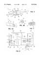
- FIG. 1is a perspective view of an illustrative embodiment of apparatus constructed in accordance with the present invention
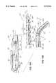
- FIGS. 2A, 2B and 2Care, respectively, a cross-sectional elevation view of the handpiece of FIG. 1, a detailed side-sectional view of the distal end of the handpiece of FIG. 2A, and a sectional view along line 2B--2B of FIG. 2A;
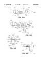
- FIG. 3is a perspective view of a portion of the drive train of the handpiece of FIG. 2;
- FIG. 4is a partial perspective view of a portion of a flexible coupling used in a preferred drive train of the present invention.
- FIGS. 5A and 5Bare, respectively, a partial perspective and end view of the end region of the device of FIG. 2;
- FIG. 6is a schematic view of an illustrative embodiment of the controller of FIG. 1;
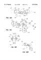
- FIGS. 7A and 7Bare, respectively, side sectional and end views of a coupling and latch mechanism for interconnecting the cable to the controller;
- FIG. 8is a sectional view of the cable of the apparatus of FIG. 1, taken along view line 8--8 of FIG. 1;
- FIGS. 9A to 9E and 9Fare, respectively, side views of the cutting head of FIG. 2 as it penetrates a thickness of tissue, and a graph showing the linear speed of the cutting head as a function of displacement;
- FIG. 10is a partial perspective view of an alternative embodiment of the stabilization means of FIG. 2A;
- FIGS. 11A and 11Bare side sectional views of further alternative embodiments of the stabilization means of FIG. 2A;
- FIGS. 12A to 12Fare perspective views, partly in block diagram form, illustrating different cutting modalities suitable for use with apparatus constructed in accordance with the present invention
- FIGS. 13A and 13Bare side sectional views of the handpiece of the present invention having an alternative embodiment of the articulation mechanism constructed in accordance with the present invention
- FIG. 14is a side sectional view of the handpiece of the present invention having another alternative embodiment of the articulation mechanism
- FIGS. 15A-15Dare, respectively, perspective views in the straight and angled position, an exploded perspective view, and partial side view of an illustrative embodiment of the mechanism of FIG. 14;
- FIGS. 16A-16Dare, respectively, perspective views in the straight and angled position, an exploded perspective view, and partial side view of an alternative embodiment of the mechanism of FIG. 14.
- the present inventionrelates generally to apparatus used to perform surgery by forming a channel in a wall of an organ, and more particularly, for intraoperatively performing transmyocardial revascularization. Unlike previously known laser apparatus developed for TMR, the present invention may be implemented in apparatus having a single use handpiece that employs relatively few mechanical and electrical components.
- Apparatus 10includes handpiece 11 coupled to controller 12 via multi-lumen cable 13.
- Handpiece 11includes end region 14 having cutting head 15 for forming transmural channels in an organ, such as the heart.
- Controller 12houses the mechanisms that drive cutting head 15, as well as one or more vacuum sources that aspirate severed tissue from the operative site.
- Handpiece 11 and cable 13preferably are pre-sterilized and discarded after a single use, while controller 12 is generally kept outside the sterile field and is reusable.
- only a portion of the handpiece, such as the elongated shaft and cutting head, described hereinafter,are disposable after a single use, while the body of the handpiece and cable are sterilizable for repeated use.
- Handpiece 11includes control panel 16 having buttons 17a-17c, body 18, tissue filter compartment 19, connector 20, elongated shaft 21 and articulation control means 22. As described in detail hereinafter, buttons 17a-17c on control panel 16 control actuation of apparatus 10.
- Body 18serves as a hand grip that permits a clinician to manipulate the handpiece, while articulation control means 22 enables the clinician to articulate end region 14.
- Tissue filter compartment 19is sealed by removable plug 23, and houses a filter that collects tissue aspirated from the operative site during the channel forming process.
- Proximal end 31preferably includes two lumens, which connect, respectively, to high and low level suction vacuum pumps in controller 12.
- Proximal end 32couples cutting head 15 and the electronic elements of handpiece 11, including control panel 16, to controller 12.
- Controller 12illustratively includes one or more vacuum sources coupled to traps 33, a coupling to accept proximal end 31 of cable 13, feature selection buttons 34, display panel 35, indicator lights 36, coupling and latch mechanism 37, and power switch 38.
- Controller 12houses a power supply that powers the drive mechanisms, vacuum pumps, and electronics from standard 60 Hz AC current.
- Body 18,which may be cast from a high strength plastic or metal alloy, includes compartment 40 that houses control panel 16, wiring lumen 41, low level suction lumen 42 and chamber 43.
- Chamber 43is preferably a circular bore, and communicates with high level suction port 44 and drive cable lumen 45.
- Tissue filter compartment 19communicates with high level suction port 44, suction port 46, and outlet 47.
- Plug 23is removably engaged with outlet 47 of tissue filter compartment 19, so that tissue filter 48 may be periodically replaced during a procedure.
- Chamber 43also preferably includes a bore 49 in which position sensor 50, illustratively a Hall effect sensor, is disposed, with the wires from sensor 50 routed from bore 49 through compartment 40 and wiring lumen 41.
- Elongated shaft 21is coupled to distal end of body 18, and comprises rigid proximal portion 55, articulation region 57 and stabilization means 58.
- Bore 59runs the length of elongated shaft 21.
- stabilization means 58includes suction cup 60 having bore 61 that communicates with the distal end of bore 59 of elongated shaft 21.
- the proximal end of bore 59opens into chamber 62 formed in the distal endface of body 18.
- Rigid portion 55 of elongated shaft 21preferably comprises a relatively rigid material, such as stainless steel.
- Articulation region 57preferably comprises soft and flexible material 63, such as silicone, which is coated onto helical wire coil 64, for example, by sintering.
- articulation region 57is shown comprising helical wire 64 captured between inner layer 63a and outer layer 63b of flexible material 63.
- Tendon 65is connected at one end to stabilization means 58 and at the other to axle 66 of articulation control means 22, illustratively thumb wheel 67. When thumbwheel 67 is rotated in a counterclockwise direction, tendon 65 causes stabilization means 58 to deflect from the longitudinal axis of the elongated shaft, as depicted in FIG. 1. Applicant expects this feature to be particularly advantageous in articulating end region 14 to permit access to posterior or otherwise hard-to-reach regions of the left ventricle.
- Cutting head 15comprises tube 70 having sharpened distal end 71 and bore 72.
- Tube 70is affixed to drive coupling 56, which in turn is disposed for reciprocatory and rotary motion in a portion of stabilization means 58 forming bushing 73.
- cutting head 15, formed of tube 70 and the distal end of drive coupling 56may be extended beyond distal endface 74 of stabilization means 58 by approximately 40 mm, while rotating at speeds of 50-50,000 RPM.
- Tube 70preferably comprises a rigid biocompatible material, such as stainless steel, having a wall thickness of 0.002 to 0.005 inches, and a length of about 0.1-0.5 inches.
- Tube 79may be affixed to drive coupling 56 by any suitable means, including welding or soldering, and preferably includes filets 70a, e.g., formed of solder, which provide a gradual taper between the exterior of tube 70 and drive coupling 56.
- filets 70ae.g., formed of solder, which provide a gradual taper between the exterior of tube 70 and drive coupling 56.
- Drive coupling 56is connected at its proximal end to drive tube 76, for example, by welding.
- Drive coupling 56preferably comprises a counterwound helical coil having inner coil 56a wound in a first direction and covered by outer coil 56b wound in an opposite direction.
- Drive coupling 56is in turn enclosed within guide sheath 75.
- guide sheath 75preferably comprises a tight pitch helical coil 77 or tubular metal mesh covered with soft elastomer 78, such as polytetrafluoroethylene (PTFE).
- PTFEpolytetrafluoroethylene
- guide sheath 75may comprise a tube of a flexible polymer, such as polyethylene.
- Drive coupling 56has central lumen 79 that communicates with bore 72 of tube 70 at its distal end and bore 80 of drive tube 76 at its proximal end. Coupling 56 transmits rotational and linear motion of drive tube 76 to cutting head 15, while guide sheath 75 maintains a high level of suction in lumen 79, even when articulation of articulation region 57 causes the flexible coupling to assume an angled shape, e.g., up to a 180° angle.
- Drive tube 76is coupled at its proximal end to spool 81.
- spool 81comprises tube 82 having closed distal face 83, frustoconical portion 81 formed by struts 84, and hub 85.
- Distal face 83includes central aperture 86 and a flange (not shown) that accepts the proximal end of drive tube 76.
- Hub 85couples spool 81 to drive cable 87.
- Drive cable 87extends to proximal end 32 of cable 13.
- Tube 82includes two regions 88 of magnetic material disposed in evenly spaced-apart relation around its circumference.
- Spool 81is enclosed within chamber 43 of body 18 so that it may rotate and translate in the longitudinal direction within chamber 43 responsive to force and torque applied by drive cable 87.
- Spool 81also may include wiper seal 82a comprising, for example, an elastomeric flange, to wipe tissue from the interior diameter of chamber 43 and prevent its buildup in the path of travel of spool 81. Seal 82a may, in addition, assist in maintaining the high level of suction in chamber 43.
- Drive tube 76is disposed through bushing 89.
- Bushing 89in turn is disposed in plug 90, which is seated in the distal end of chamber 43.
- Plug 90preferably is installed during the manufacturing process, after spool 81 (already connected to drive cable 87 and drive tube 76) is disposed in chamber 43.
- Drive cable 87is also disposed through bushing 91, which is seated in recess 92 in drive cable lumen 45.
- Tissue filter 48preferably comprises a replaceable light-weight membrane or mesh, e.g., formed from paper or a polymer mesh or screen.
- Regions 88 of magnetic material on spool 81provide two safety functions that enable controller 12 to monitor operation of handpiece 11.
- sensor 50generates a signal only when the magnetic material on spool 81 is aligned with the sensor, for example, when the spool is in its proximal-most position.
- regions 88 and sensor 50enable controller 12 to determine the location of the spool within chamber 43, for example, to ensure that the cutting head has fully retracted after a boring a channel in tissue.
- the presence of magnetic regions 88enables controller 12 to determine that spool 81 is rotating within chamber 43 by detecting periodic fluctuations in the output of sensor 50.
- the frequency of the signal output by sensor 50should be directly proportional to the rotational speed of spool 81 within chamber 43.
- sensors of other typesmay be advantageously employed to provide positional information in place of Hall effect sensor 50 and magnetic regions 88.
- Stabilization means 58illustratively comprises suction cup 60 in distal endface 74, and beveled portion 95.
- tube 70 of cutting head 15is shown slightly extended from distal endface 74 of the stabilization means.
- stabilization means 58comprises a transparent material, such as silicone, polyurethane, polyethylene, polypropylene or polycarbonate, so that the path of cutting head 15 is visible.
- Bushing 73 of stabilization means 58also preferably comprises a layer of low frictional material, e.g., polytetrafluoroethylene (teflon), to support cutting head 15.
- Controller 12comprises housing 100 containing vacuum equipment compartment 101 separated by environmental wall 102 from drive assembly and electronics compartment 103.
- Vacuum equipment compartment 101preferably contains high level vacuum pump 104 and low level vacuum pump 105.
- High level vacuum pump 104preferably creates a high level of suction, e.g., between about 400-800 mm Hg, and preferably about 730 mm Hg, while low level vacuum pump creates a lower level of suction, e.g., less than 400 mm Hg and preferably, about 250 mm Hg.
- Vacuum pumps 104 and 105are coupled to traps 33 via coupling 106, which are in turn coupled to proximal end 31 of cable 13 via coupling 107.
- the inlet line for each vacuum pumpincludes flow sensor 108 and pressure sensor 109.
- Control electronics 110monitors the outputs of sensors 108 and 109 to ensure that apparatus 10 is functioning properly, e.g., to ensure that there are no excursions indicating a blocked line.
- drive assembly and electronics compartment 103houses control electronics 110, e.g., a suitably programmed microprocessor or analog circuitry, power supply 111, linear motor 112, rotary motor 113, drive tube 114, display panel 35, indicator lights 36, coupling and latch mechanism 37, and power switch 38.
- Linear motor 112which may be either a linear stepper motor or a rotary motor coupled to a lead screw arrangement, is connected to drive tube 114 by coupling 115, and causes drive tube 114 to be reciprocated with respect to the longitudinal axis of drive tube 114.
- this motionis translated through drive cable 87, it causes cutting head 15 to extend and retract beyond distal endface 74 of stabilization means 58 (see FIG. 2A).
- Rotary motor 113is coupled to drive tube 114 by right angle gearing 116.
- Drive tube 114preferably includes a D-shaped outer diameter, so that a gear of right angle gearing 116 having a mating key slot continuously transmits torque to drive tube 114 even while it is being extended or retracted by linear motor 112.
- Motors 112 and 113are each coupled to control electronics 110, which activates the motors responsive to signals generated by the buttons of control panel 16 on handpiece 11.
- Indicator lights 36preferably provide information concerning the state of the apparatus. For example, one of the lights 36 may become illuminated to indicate that the cutting head is ready to be activated, while the other indicates that the apparatus is in a standby mode.
- Display panel 35also may display information concerning the state of the apparatus, such as the instantaneous suction levels, flow rates and error messages, as well as, for example, provide information regarding the rotational speed of the cutting head, and the number and depth of channels formed.
- Mechanism 37is configured to engage outer sheath 120 of proximal end 32 of cable 13 in a stationary manner, while enabling drive cable 87 to engage drive tube 114 for reciprocatory and rotary motion.
- Mechanism 37comprises housing 121 having hoop 122 disposed in slot 123 for sliding movement, and sleeve 124 disposed on ring 125.
- Ring 125includes balls 126 captured in bores 127, and is affixed to the distal end of drive tube 114.
- Hoop 122has pivot pins 128 engaged in slots 129 of cams 130, while sleeve 124 has pivot pins 131 engaged in slots 132 of cams 130.
- cams 130are fixed to pivot on pins 133.
- Hoop 122includes button 134 and spring 135 that biases the hoop 122 in a retracted position in slot 123.
- Sleeve 124has chamfer 136 along the interior of its proximal end, so that when sleeve 124 is in its relaxed position, balls 126 project into the interior of ring 125.
- mechanism 37Operation of mechanism 37 is as follows: when it is desired to connect proximal end 32 of cable 13 to controller 12, drive tube 114 and ring 125 are moved to the proximal-most position in sleeve 124. The clinician then depresses button 134 against the bias of spring 135. This causes hoop 122 to move downward in slot 123, so that the opening in hoop 122 is aligned with opening 137 of housing 121. Downward movement of hoop 122 also causes pins 128 to ride downward in slot 129, thereby causing cams 130 to rotate (e.g., counterclockwise in FIG. 7A). As cams 130 rotate, slots 132 exert a force on pivot pins 131 which draw sleeve 124 towards hoop 122. This movement of sleeve 124 releases balls 126 in ring 125.
- Proximal end 32 of cable 13is then inserted in mechanism 37.
- the proximal end of drive cable 87is inserted into ring 125 until balls 126 enter detent 138 in the drive cable.
- the proximal end of outer sheath 120also extends into the opening in hoop 122.
- spring 135causes hoop 122 to engage outer sheath 120 of the cable 13, thus locking the outer sheath in place.
- upward movement of hoop 122causes cams 130 to rotate sufficiently for sleeve 124 to be urged by pivot pin 131 away from hoop 122.
- sleeve 124This motion causes sleeve 124 to retain balls 126 in detent 138 of drive cable 87.
- sleeve 124preferably should have a length L sufficient to accommodate the full stroke of drive tube 114.
- Cable 13is preferably sufficiently long, e.g., approximately 1 to 1.5 m long, for controller 12 to be placed outside the sterile field during operation of apparatus 10.
- Cable 13comprises a flexible material, such as polyethylene, which is extruded to form lumens 140-143.
- each of lumens 140-143may be separately formed and then bonded together or enclosed within a common sheath, such as a heat shrinkable sheath.
- lumen 140is coupled to low level suction lumen 42 of handpiece 11
- lumen 141is coupled to suction port 47 of handpiece 11
- lumen 142is used for routing electrical wires between handpiece 11 and controller 12
- lumen 143houses drive cable 87.
- Lumen 143may be lined with a lubricious material, such as PTFE, to reduce friction between drive cable 87 and the walls of the lumen.
- proximal ends 31 and 32 of cable 13are coupled to controller 12, and power switch 38 is turned on.
- Controller 12may then be programmed via feature selection buttons 34, or a keyboard (not shown), for example, to select the depth of the transmural channels to be cut and the parameters displayed on display panel 35.
- a portion of the patient's left ventricleis exposed by thorocotomy or through apertures opened between the patient's ribs.
- the clinicianfirst depresses button 17a to "arm" the handpiece, which signals controller 12 to activate vacuum pumps 104 and 105, and activate rotary motor 113 to rotate drive tube 114. This rotation is transmitted from drive cable 87 to spool 81, and then through drive tube 76 and drive coupling 56 to cutting head 15.
- the clinicianmanipulates handpiece 11 to bring distal endface 74 of stabilization means 58 into contact with the epicardium in the vicinity of the left ventricle, either with or without articulation of end region 14, as required by the access conditions of the operative site.
- controller 12may include, for example, a gate valve in coupler 106 that rotates responsive to control electronics 110 and the signal from button 17c to alternate between a bleed port and the connection to lumen 140. In this manner, low-level suction may be selectively provided through suction cup 60 responsive to actuation of button 17c.
- buttons 17bAfter distal end 14 of handpiece 11 is engaged with the target tissue, the clinician actuates button 17b to initiate the transmural cutting process. Specifically, when button 17b is depressed, control electronics 110 activates linear motor 112 to cause drive tube 114 to extend and retract with a preselected velocity profile input. This longitudinal movement of drive tube 114 is transmitted via drive cable 87 to cutting head 15, which extends through the ventricle wall and then retracts. Simultaneous with this longitudinal motion, cutting head 15 is rotated at high speed and high level suction is drawn through bore 72 of the cutting head to aspirate severed tissue.
- Tissue aspirated from the target siteis drawn through drive coupling 56 and drive tube 76 and exits into the interior of spool 81, from which it is drawn through chamber 43 into tissue filter 48.
- controller 12may alert the clinician when the suction through cutting head 15 has dropped, for example, due to filling of tissue filter 48. The clinician may then, between channel forming steps, remove plug 23 and replace tissue filter 48 with a clean filter.
- extension and retraction of cutting head 15may be readily accomplished during diastole of a single cardiac cycle (i.e., within about one-tenth to one-half of a second).
- the output of an EKG monitormay be used by the clinician to time initiation of the tissue cutting process with the onset of diastole.
- the cliniciandepresses button 17c to cease low level suction through suction cup 60, thereby disengaging stabilization means 58 from the tissue. It has been observed that the outlet of the transmural channel will clot off in a few minutes, leaving a channel through which blood from the left ventricle may perfuse the myocardium. The clinician then repositions the cutting head to an adjacent region of the epicardium, including adjusting the degree of articulation of end-region 14, and repeats the process.
- articulation control means 22enables the degree of articulation of end-region 14 to be adjusted in situ and as required to obtain access for the selected area to be treated.
- handpiece 11may include a fiber optic cable for viewing the target site and angulation of the end-region in such regions.
- FIGS. 9A to 9Fa speed control feature of a preferred embodiment of the present invention is described.
- FIGS. 9A to 9Ethe position of cutting head 15 at a series of consecutive displacements X 0 -X 4 is shown during the process of forming a transmural channel in tissue T.
- FIG. 9Fdepicts the speed of the cutting head at each of the displacements illustrated in FIGS. 9A to 9E.
- the linear speed of cutting head 15varies in accordance with the depth of penetration of the cutting head into tissue T. As shown in FIGS. 9C and 9D, as the cutting head nears the inner surface of the tissue wall (near completion of the channel formation), the speed of the cutting head is reduced to provide adequate time for the high level suction to aspirate severed material. In this manner, the potential for ejecting severed material into the organ from the distal surface of the tissue is reduced, and thus the risk of embolization is reduced. After the cutting head has completely penetrated the tissue wall, the cutting head is rapidly retracted.
- control electronics 110may be programmed to control the speed at which linear motor 112 reciprocates drive tube 114 to provide a speed profile such as described above with respect to FIG. 9F.
- Control electronics 110may in addition employ additional positional information generated by an extended position sensing element (not shown) similar to Hall effect sensor 50 to more accurately control the speed profile.
- control electronics 110may also employ the signal generated by pressure sensor 109 to determine when the cutting head has completely penetrated the tissue.
- Stabilization means 150includes suction cup 151, bore 152 for the cutting head, and light source 153, e.g., a light emitting diode (LED) or laser diode, disposed in the transparent material forming stabilization means 150.
- Light source 153is connected to a suitable power supply by lead wires 154 and 155. When a voltage is supplied across lead wires 154 and 155, light source 153 emits light that exits the distal end face of the stabilization means in an approximately annular illumination beam to form illumination spot 156.
- illumination spot 156may be advantageously used to position the stabilization means 150 on the tissue so that suction cup 151 does not overlap a site at which a transmural channel had been previously formed.
- shaft 21may include a spring-loaded retractable stylet (not shown) that indicates the position of the suction cup before the suction cup is engaged to the tissue.
- stabilization means 160is similar in design to that of FIG. 5A, except that beveled surface 95 is replace with fixed tube 161 having beveled sharpened tip 162 and lumen 163.
- the bevel of tip 162renders the tip non-coring, so that when the beveled end of tube 161 is inserted into the tissue, a flap of tissue is cut and folded back, rather than severed.
- the cutting head in this embodimentis reciprocated through lumen 163, and otherwise operates as described hereinabove.
- Applicantexpects that use of beveled tube 161 will accelerate the process of clotting of the transmural channel on the epicardium, by reducing the amount of tissue removed from outer thickness of the tissue wall, and leaving a slit instead of a cored cut channel at the surface.
- FIG. 11Ban alternative embodiment of the stabilization means of FIG. 11A is shown, in which beveled tip 164 of tube 165 is disposed flush with, or slightly recessed from, distal endface 166 of stabilization means 167.
- beveled tip 164does not pierce the surface of the tissue until the high level suction draws the tissue inwards through opening 168.
- FIG. 11Bwill provide the same advantage as the embodiment of FIG. 11A, i.e., less outer wall tissue removal and faster hemostasis, but with a lower risk of inadvertently piercing or tearing the tissue while repositioning the distal end of the device.
- FIGS. 12A to 12Fdifferent modalities of operation of a cutting head constructed in accordance with the present invention are described.
- various cutting headsare described as illustratively constructed from a sharpened tubular member, similar to that described with respect to FIG. 2A.
- All of the embodiments of FIGS. 12A to 12E described hereinbelowpreferably include a central lumen that may be coupled to a vacuum source for aspirating tissue severed by the cutting head from the treatment site, thus reducing the risk of embolization.
- cutting head 170is arranged for rotary and longitudinal motion, like cutting head 15 described hereinabove.
- cutting head 172is arranged for rapid reciprocation in the distal and proximal directions, which motion is superimposed on the distal and proximal motion of the cutting head caused by actuation of the linear motor 112.
- cutting head 174is reciprocated rapidly in the longitudinal direction while experiencing rapidly alternating angular motion of several degrees, for example, 90 to 120 degrees, which motion is again superimposed on the overall distal and proximal motion caused by linear motor 112.
- cutting head 176is vibrated at high frequency, either in the longitudinal direction, an angular direction, or both, to cause emulsification of the tissue contacted by the cutting head. Vibration of cutting head 176 may be accomplished either by a mechanical gear driven arrangement, or may be provided by an ultrasonic device. In either case, the vibratory motion of the cutting head is in addition to motion in the distal and proximal directions caused by actuation of linear motor 112.
- cutting head 178is described together with actuator 180.
- Cutting head 178is advanced at very high speed in the distal direction, for example, by a hydraulic actuator, to pierce the heart tissue in a single motion.
- drive tube 76need not be rotated, and linear motor 112 of controller 12 is replaced by actuator 180 comprising piston 181 that reciprocates within cylinder 182, valving 183 that selectively couples piston 181 to source of high pressure 184 (e.g., a cylinder of pressurized gas) and a source of low pressure 185 (e.g., a vacuum source).
- source of high pressure 184e.g., a cylinder of pressurized gas
- source of low pressure 185e.g., a vacuum source
- Cutting head 190comprises a nozzle through which fluid, for example, saline, is ejected at high pressure, for example 1000 psi. The fluid stream impinges upon and cuts a channel in the tissue.
- drive tube 76remains stationary and motors 112 and 113 are replaced by a high pressure hydraulic pump 192.
- Handpiece 200comprises body 201 configured as described above with respect to body 18 of FIG. 2A, and houses control panel 202, spool 203, drive cable 204, drive tube 205 and tissue filter 206, all as described above with respect to like parts of FIG. 2A.
- Elongated shaft 210is coupled to the distal end of body 201, and comprises rigid proximal portion 211, articulation region 212 and stabilization means 213. Bore 214 runs the length of elongated shaft 210. Stabilization means 213 comprises suction cup 215 and bushing 216 in which cutting head 217 rotates and reciprocates, as described hereinabove with respect to like parts in FIG. 2A.
- Drive tube 205is coupled to cutting head 217 by drive coupling 218, as described above with respect to FIGS. 2A and 2B. Alternatively, drive tube 205 may be omitted, with drive coupling 218 being connected directly to spool 203. Drive coupling 218 is enclosed within guide sheath 219.
- articulation region 212comprises a plurality of interconnected segments 220.
- Segment 220acouples articulation region 212 to proximal region 211 and includes curved flange 221
- segment 220bcouples the articulation region to stabilization means 213 and includes ridge 222.
- Each of segments 220c disposed between segments 220a and 220bincludes both curved flange 221 at its distal end and ridge 222 at its proximal end.
- Each ridge 222is slidingly captured on the curved flange of the next proximal segment. In this manner, each segment may be rotated slightly so that its longitudinal axis forms an angle with the longitudinal axis of the preceding segment.
- stabilization means 213may be positioned at an angle ⁇ , e.g., 45° or 90° , with respect to the longitudinal axis of proximal portion 211.
- each ridge 222is frictionally coupled to the preceding curved flange 221, so that segments 220 may be bent to a desired shape and will retain that shape until subsequently moved.
- the clinicianfirst adjusts the position of the cutting head, and then inserts elongated shaft 210 to reach the operative site.
- an articulation control mechanism and tendonmay be provided to adjust the degree of angulation of articulation region 212 in-situ.
- body 201 and elongated shaft 210may in addition include lumen 225 containing fiber optic element 226.
- Fiber optic element 226is coupled to lens 227 at its distal end, and to an imaging system (not shown), per se known, at its distal end. Accordingly, fiber optic element 226 may be used to view the target site, the degree of articulation of the end region of elongated shaft 210, and the operation of cutting head 217.
- lens 227has a field of view ⁇ that encompasses the useful range of movement of stabilization means 213, e.g., about 15° to 60° from the longitudinal axis of shaft 210, depending upon the axial distance D from the stabilization means to the lens 227.
- This featuremay be advantageously employed, for example, with handpiece 11 of FIG. 2A, to enable the clinician to view adjustments of the articulation of the stabilization means and cutting head in-situ without removing the end region from the operative site.
- Handpiece 230includes body 231 including spool 232, drive cable 233, drive tube 234, control panel 235, and tissue filter 236 as described hereinabove with respect to FIG. 2A.
- Cutting head 237is coupled to drive tube 234 by drive coupling 238 enclosed in guide sheath 239, as described hereinabove with respect to previous embodiments.
- Elongated shaft 240is coupled to the distal end of body 231, and includes rigid proximal and distal portions, 241 and 242, respectively, coupled to articulation region 243.
- Articulation region 243preferably comprises helical coil 244 coated with elastomeric material 245, as described herein above with respect to FIG. 2A.
- Stabilization means 246is coupled to the distal end of distal portion 242.
- Handpiece 230differs from handpiece 11 of FIG. 2A in that articulation control means 67 and tendon 65 are replaced with adjustable pivot assembly 250.
- Pivot assembly 250includes hinged portions 251 and 252 coupled by pin 253. Each of hinged portions 251 and 252 is connected to proximal and distal portions 241 and 242, respectively, of elongated shaft 240.
- joint 254 formed by hinged portions 251, 252 and pin 253may be adjusted to a desired angle, and holds the selected shape until subsequently readjusted.
- Articulation region 243bends to conform to the shape imposed by pivot assembly 250.
- adjustable pivot assembly 250may manually adjust the cutting head to a desired angle, for example, to access hard-to-reach portions of the anatomy, and then position the end-region in the operative site to form transmural channels.
- adjustable pivot assembly 250Specific embodiments of adjustable pivot assembly 250 are described below with respect to FIGS. 15 and 16.
- hinged portion 251includes tubular member 255, which engages proximal portion 241
- hinged portion 252includes tubular member 256 which engages distal portion 242.
- hinged portions 251 and 252may omit tubular members 255 and 256, and instead be affixed directly to the rigid portions of the shaft 240, e.g., by welding.
- Hinged portion 251includes washers 258 having grooves 259 and buttons 260. Washers 258 are disposed from the distal end of hinged portion 251 to form yoke 261. Hinged portion 252 includes washers 262 having ribs 263 disposed about apertures 264 to form yoke 265. When assembled, yoke 261 of hinged portion 251 is disposed within yoke 265, so that buttons 260 extend through apertures 264 and grooves 259 and ribs 263 are arranged in opposing relation. Spring 266 is disposed about pin 253, which in turn is slidingly engaged in bores (not shown) within buttons 261.
- spring 266When assembled, spring 266 applies a compressive load on washers 258 that urges them against washers 262. This force compresses the washers together and urges grooves 259 and ribs 263 to intermesh, thus preventing rotation of one hinged portion relative to the other.
- spring 266By depressing buttons 260 as illustrated by arrows F in FIG. 15D, spring 266 may be compressed against its bias, and hinged portion 252 may be rotated relative to hinged portion 251, so that distal portion 242 of elongated shaft 240 forms an angle ⁇ with respect to the longitudinal axis of proximal portion 241 of the shaft.
- buttons 260Once the clinician has articulated the cutting head to a desired angle, buttons 260 are released, thereby causing grooves 259 and ribs 263 to again intermesh and lock the hinged portions into position.
- Pivot assembly 270is similar in construction to pivot assembly 250 of FIGS. 15.
- Hinged portion 271is coupled to proximal portion 241 of elongated shaft 240 by tubular member 272, while hinged portion 273 is coupled to distal portion 242 by tubular member 274.
- Hinged portion 271includes washers 275 having grooves 276 and apertures 277.
- Hinged portion 273includes washers 278 having ribs 279 disposed around apertures 280. Washers 275 are disposed from the distal end of hinged portion 271 to form yoke 281, while washers 278 form yoke 282 on hinged portion 273.
- yoke 281 of hinged portion 271When assembled, yoke 281 of hinged portion 271 is disposed within yoke 282, so that grooves 277 and ribs 279 are arranged in opposing relation.
- Pin 283is disposed through apertures 277 and 280 and engaged with nut 284, and captures concave lock washers 285 against the exterior surfaces of washers 278.
- lock washers 284When assembled, lock washers 284 apply a compressive load on washers 278 that urges them against washers 275. This force compresses the washers together and urges grooves 277 and ribs 279 to intermesh, thus preventing rotation of one hinged portion relative to the other.
- the concave shape of lock washers 285enable ribs 279 to slide or ratchet pass grooves 277 when a sufficiently high bending force is manually applied to hinged portions 271 and 273.
- the clinicianmay manually rotate hinged portion 271 relative to hinged portion 273 so that distal portion 242 of elongated shaft 240 forms an angle with respect to the longitudinal axis of proximal portion 241 of the shaft. Once the clinician has articulated the cutting head to a desired angle, grooves 277 and ribs 279 again intermesh and lock the hinged portions into position.
Landscapes
- Health & Medical Sciences (AREA)
- Life Sciences & Earth Sciences (AREA)
- Surgery (AREA)
- Engineering & Computer Science (AREA)
- Animal Behavior & Ethology (AREA)
- Veterinary Medicine (AREA)
- Biomedical Technology (AREA)
- Heart & Thoracic Surgery (AREA)
- Medical Informatics (AREA)
- Molecular Biology (AREA)
- Nuclear Medicine, Radiotherapy & Molecular Imaging (AREA)
- General Health & Medical Sciences (AREA)
- Public Health (AREA)
- Vascular Medicine (AREA)
- Orthopedic Medicine & Surgery (AREA)
- Neurology (AREA)
- Neurosurgery (AREA)
- Physics & Mathematics (AREA)
- Plasma & Fusion (AREA)
- Otolaryngology (AREA)
- Surgical Instruments (AREA)
Abstract
Description
Claims (26)
Priority Applications (3)
| Application Number | Priority Date | Filing Date | Title |
|---|---|---|---|
| US09/027,828US5972012A (en) | 1997-10-17 | 1998-02-19 | Cutting apparatus having articulable tip |
| AU10934/99AAU1093499A (en) | 1997-10-17 | 1998-10-16 | Remotely driven and aspirated cutting apparatus |
| PCT/US1998/021881WO1999020187A1 (en) | 1997-10-17 | 1998-10-16 | Remotely driven and aspirated cutting apparatus |
Applications Claiming Priority (2)
| Application Number | Priority Date | Filing Date | Title |
|---|---|---|---|
| US08/953,046US5899915A (en) | 1996-12-02 | 1997-10-17 | Apparatus and method for intraoperatively performing surgery |
| US09/027,828US5972012A (en) | 1997-10-17 | 1998-02-19 | Cutting apparatus having articulable tip |
Related Parent Applications (1)
| Application Number | Title | Priority Date | Filing Date |
|---|---|---|---|
| US08/953,046Continuation-In-PartUS5899915A (en) | 1996-12-02 | 1997-10-17 | Apparatus and method for intraoperatively performing surgery |
Publications (1)
| Publication Number | Publication Date |
|---|---|
| US5972012Atrue US5972012A (en) | 1999-10-26 |
Family
ID=46253967
Family Applications (1)
| Application Number | Title | Priority Date | Filing Date |
|---|---|---|---|
| US09/027,828Expired - LifetimeUS5972012A (en) | 1997-10-17 | 1998-02-19 | Cutting apparatus having articulable tip |
Country Status (1)
| Country | Link |
|---|---|
| US (1) | US5972012A (en) |
Cited By (69)
| Publication number | Priority date | Publication date | Assignee | Title |
|---|---|---|---|---|
| US6152894A (en)* | 1997-10-27 | 2000-11-28 | Kubler; Harald | Surgical cutting instrument |
| US6224617B1 (en)* | 1997-10-17 | 2001-05-01 | Angiotrax, Inc. | Methods and apparatus for defibrillating a heart refractory to electrical stimuli |
| US6461349B1 (en)* | 1997-10-24 | 2002-10-08 | Carl Zeiss Meditec Ag | Medical handpiece with a light guide which can be displaced in an axial direction |
| US6464693B1 (en) | 2000-03-06 | 2002-10-15 | Plc Medical Systems, Inc. | Myocardial revascularization |
| US20030163158A1 (en)* | 2000-06-22 | 2003-08-28 | White Geoffrey H. | Method and apparatus for performing percutaneous thromboembolectomies |
| US20030176778A1 (en)* | 2002-03-15 | 2003-09-18 | Scimed Life Systems, Inc. | Medical device control systems |
| US20030187460A1 (en)* | 1999-08-10 | 2003-10-02 | Chin Albert K. | Methods and apparatus for endoscopic cardiac surgery |
| US20040034343A1 (en)* | 2002-08-16 | 2004-02-19 | Gillespie Walter D. | Articulation mechanism |
| US20040181249A1 (en)* | 2003-03-10 | 2004-09-16 | Pathway Medical Technologies, Inc. | Bearing system to support a rotatable operating head in an intracorporeal device |
| US20050033357A1 (en)* | 2003-04-01 | 2005-02-10 | Marcus Braun | Surgical instrument comprising an instrument handle and zero point adjustment |
| US20060065649A1 (en)* | 2004-03-02 | 2006-03-30 | Fredrick William G Jr | Method for remote controlled actuation of laser processing head |
| US20070129628A1 (en)* | 2005-12-02 | 2007-06-07 | The Cooper Health System | Regional anesthetic method and apparatus |
| US20070167829A1 (en)* | 2005-12-02 | 2007-07-19 | Robert Hirsh | Regional anesthetic method and apparatus |
| US20070244371A1 (en)* | 2006-04-04 | 2007-10-18 | Nguyen Hoa D | Phlebectomy illumination device and methods |
| US20070249908A1 (en)* | 2006-04-24 | 2007-10-25 | Ifung Lu | Medical cannula and medical cannula system |
| US20070250111A1 (en)* | 2006-04-25 | 2007-10-25 | Ifung Lu | Medical instrument having an articulatable end effector |
| US20070249905A1 (en)* | 2006-04-25 | 2007-10-25 | Nobis Rudolph H | Medical tubular assembly |
| US20070250012A1 (en)* | 2006-04-24 | 2007-10-25 | Ifung Lu | Medical instrument having a medical needle-knife |
| US20070255312A1 (en)* | 2006-05-01 | 2007-11-01 | Ifung Lu | Medical instrument having an end-effector-associated member |
| US20070260264A1 (en)* | 2006-05-04 | 2007-11-08 | Nobis Rudolph H | Medical instrument handle and medical instrument having same |
| EP1857061A1 (en)* | 2006-05-16 | 2007-11-21 | Ethicon Endo-Surgery, Inc. | Medical instrument having a needle knife |
| US20070270649A1 (en)* | 2006-05-18 | 2007-11-22 | Long Gary L | Medical instrument including a catheter having a catheter stiffener and method for using |
| US20070282187A1 (en)* | 2006-05-11 | 2007-12-06 | Long Gary L | Medical instrument having a catheter and method for using a catheter |
| US7597698B2 (en) | 1999-08-10 | 2009-10-06 | Maquet Cardiovascular Llc | Apparatus and method for endoscopic encirclement of pulmonary veins for epicardial ablation |
| US7703653B2 (en) | 2007-09-28 | 2010-04-27 | Tyco Healthcare Group Lp | Articulation mechanism for surgical instrument |
| US7713190B2 (en)* | 1998-02-24 | 2010-05-11 | Hansen Medical, Inc. | Flexible instrument |
| US20100280328A1 (en)* | 2009-05-01 | 2010-11-04 | Tyco Healthcare Group, Lp | Methods and systems for illumination during phlebectomy procedures |
| EP2298220A1 (en)* | 2001-02-15 | 2011-03-23 | Hansen Medical, Inc. | Flexible instrument |
| US20110137231A1 (en)* | 2009-12-08 | 2011-06-09 | Alcon Research, Ltd. | Phacoemulsification Hand Piece With Integrated Aspiration Pump |
| US20110144567A1 (en)* | 2009-12-15 | 2011-06-16 | Alcon Research, Ltd. | Phacoemulsification Hand Piece With Integrated Aspiration Pump and Cartridge |
| US8211114B2 (en) | 2006-04-24 | 2012-07-03 | Ethicon Endo-Surgery, Inc. | Medical instrument having a medical snare |
| US20140330272A1 (en)* | 2013-05-03 | 2014-11-06 | Olympus Winter & Ibe Gmbh | Application probe |
| US8961551B2 (en) | 2006-12-22 | 2015-02-24 | The Spectranetics Corporation | Retractable separating systems and methods |
| US9028520B2 (en) | 2006-12-22 | 2015-05-12 | The Spectranetics Corporation | Tissue separating systems and methods |
| US20150230779A1 (en)* | 1999-12-17 | 2015-08-20 | Devicor Medical Products, Inc. | Surgical biopsy system with remote control for selecting an operational mode |
| US9126219B2 (en) | 2013-03-15 | 2015-09-08 | Alcon Research, Ltd. | Acoustic streaming fluid ejector |
| US9138250B2 (en) | 2006-04-24 | 2015-09-22 | Ethicon Endo-Surgery, Inc. | Medical instrument handle and medical instrument having a handle |
| US9283040B2 (en) | 2013-03-13 | 2016-03-15 | The Spectranetics Corporation | Device and method of ablative cutting with helical tip |
| US9291663B2 (en) | 2013-03-13 | 2016-03-22 | The Spectranetics Corporation | Alarm for lead insulation abnormality |
| US9413896B2 (en) | 2012-09-14 | 2016-08-09 | The Spectranetics Corporation | Tissue slitting methods and systems |
| USD765243S1 (en) | 2015-02-20 | 2016-08-30 | The Spectranetics Corporation | Medical device handle |
| US9456872B2 (en) | 2013-03-13 | 2016-10-04 | The Spectranetics Corporation | Laser ablation catheter |
| USD770616S1 (en) | 2015-02-20 | 2016-11-01 | The Spectranetics Corporation | Medical device handle |
| WO2017007442A1 (en) | 2015-07-06 | 2017-01-12 | Gaziantep Universitesi Vakfi | A cutter |
| US9545337B2 (en) | 2013-03-15 | 2017-01-17 | Novartis Ag | Acoustic streaming glaucoma drainage device |
| US9603618B2 (en) | 2013-03-15 | 2017-03-28 | The Spectranetics Corporation | Medical device for removing an implanted object |
| US9668765B2 (en) | 2013-03-15 | 2017-06-06 | The Spectranetics Corporation | Retractable blade for lead removal device |
| US9693896B2 (en) | 2013-03-15 | 2017-07-04 | Novartis Ag | Systems and methods for ocular surgery |
| US9750638B2 (en) | 2013-03-15 | 2017-09-05 | Novartis Ag | Systems and methods for ocular surgery |
| US9883885B2 (en) | 2013-03-13 | 2018-02-06 | The Spectranetics Corporation | System and method of ablative cutting and pulsed vacuum aspiration |
| US9915274B2 (en) | 2013-03-15 | 2018-03-13 | Novartis Ag | Acoustic pumps and systems |
| US9925366B2 (en) | 2013-03-15 | 2018-03-27 | The Spectranetics Corporation | Surgical instrument for removing an implanted object |
| US20180085115A1 (en)* | 2006-01-27 | 2018-03-29 | Endoevolution, Llc | Apparatus and method for tissue closure |
| US9962288B2 (en) | 2013-03-07 | 2018-05-08 | Novartis Ag | Active acoustic streaming in hand piece for occlusion surge mitigation |
| US9980743B2 (en) | 2013-03-15 | 2018-05-29 | The Spectranetics Corporation | Medical device for removing an implanted object using laser cut hypotubes |
| US10136913B2 (en) | 2013-03-15 | 2018-11-27 | The Spectranetics Corporation | Multiple configuration surgical cutting device |
| CN109069213A (en)* | 2016-03-31 | 2018-12-21 | 皇家飞利浦有限公司 | The robot system of image guidance for tumour suction |
| US10182940B2 (en) | 2012-12-11 | 2019-01-22 | Novartis Ag | Phacoemulsification hand piece with integrated aspiration and irrigation pump |
| US20190175211A1 (en)* | 2017-12-12 | 2019-06-13 | Boston Scientific Scimed, Inc. | Rotational medical device |
| US10342520B2 (en)* | 2015-08-26 | 2019-07-09 | Ethicon Llc | Articulating surgical devices and loaders having stabilizing features |
| US10383691B2 (en) | 2013-03-13 | 2019-08-20 | The Spectranetics Corporation | Last catheter with helical internal lumen |
| US10405924B2 (en) | 2014-05-30 | 2019-09-10 | The Spectranetics Corporation | System and method of ablative cutting and vacuum aspiration through primary orifice and auxiliary side port |
| US10448999B2 (en) | 2013-03-15 | 2019-10-22 | The Spectranetics Corporation | Surgical instrument for removing an implanted object |
| WO2019226419A1 (en)* | 2018-05-21 | 2019-11-28 | Smith & Nephew, Inc. | Lumen reinforcement device and system |
| US10835279B2 (en) | 2013-03-14 | 2020-11-17 | Spectranetics Llc | Distal end supported tissue slitting apparatus |
| US10842532B2 (en) | 2013-03-15 | 2020-11-24 | Spectranetics Llc | Medical device for removing an implanted object |
| US11413057B2 (en)* | 2019-06-27 | 2022-08-16 | Covidien Lp | Tissue resecting instruments including auxiliary vacuum features |
| US20240216007A1 (en)* | 2022-04-06 | 2024-07-04 | Clearstream Technologies Limited | A control handle for an atherectomy device |
| US12053203B2 (en) | 2014-03-03 | 2024-08-06 | Spectranetics, Llc | Multiple configuration surgical cutting device |
Citations (31)
| Publication number | Priority date | Publication date | Assignee | Title |
|---|---|---|---|---|
| US4788975A (en)* | 1987-11-05 | 1988-12-06 | Medilase, Inc. | Control system and method for improved laser angioplasty |
| US5125926A (en)* | 1990-09-24 | 1992-06-30 | Laser Engineering, Inc. | Heart-synchronized pulsed laser system |
| US5125924A (en)* | 1990-09-24 | 1992-06-30 | Laser Engineering, Inc. | Heart-synchronized vacuum-assisted pulsed laser system and method |
| US5242460A (en)* | 1990-10-25 | 1993-09-07 | Devices For Vascular Intervention, Inc. | Atherectomy catheter having axially-disposed cutting edge |
| US5336237A (en)* | 1993-08-25 | 1994-08-09 | Devices For Vascular Intervention, Inc. | Removal of tissue from within a body cavity |
| US5358472A (en)* | 1992-01-13 | 1994-10-25 | Schneider (Usa) Inc. | Guidewire atherectomy catheter and method of using the same |
| US5358485A (en)* | 1992-01-13 | 1994-10-25 | Schneider (Usa) Inc. | Cutter for atherectomy catheter |
| US5380316A (en)* | 1990-12-18 | 1995-01-10 | Advanced Cardiovascular Systems, Inc. | Method for intra-operative myocardial device revascularization |
| US5383884A (en)* | 1992-12-04 | 1995-01-24 | American Biomed, Inc. | Spinal disc surgical instrument |
| US5389096A (en)* | 1990-12-18 | 1995-02-14 | Advanced Cardiovascular Systems | System and method for percutaneous myocardial revascularization |
| US5403334A (en)* | 1989-09-12 | 1995-04-04 | Devices For Vascular Intervention, Inc. | Atherectomy device having helical blade and blade guide |
| US5429144A (en)* | 1992-10-30 | 1995-07-04 | Wilk; Peter J. | Coronary artery by-pass method |
| US5488958A (en)* | 1992-11-09 | 1996-02-06 | Vance Products Incorporated | Surgical cutting instrument for coring tissue affixed thereto |
| US5492119A (en)* | 1993-12-22 | 1996-02-20 | Heart Rhythm Technologies, Inc. | Catheter tip stabilizing apparatus |
| US5520634A (en)* | 1993-04-23 | 1996-05-28 | Ethicon, Inc. | Mechanical morcellator |
| US5562694A (en)* | 1994-10-11 | 1996-10-08 | Lasersurge, Inc. | Morcellator |
| US5569178A (en)* | 1995-10-20 | 1996-10-29 | Henley; Julian L. | Power assisted suction lipectomy device |
| US5569284A (en)* | 1994-09-23 | 1996-10-29 | United States Surgical Corporation | Morcellator |
| US5575772A (en)* | 1993-07-01 | 1996-11-19 | Boston Scientific Corporation | Albation catheters |
| US5575787A (en)* | 1993-09-20 | 1996-11-19 | Abela Laser Systems, Inc. | Cardiac ablation catheters and method |
| US5575293A (en)* | 1995-02-06 | 1996-11-19 | Promex, Inc. | Apparatus for collecting and staging tissue |
| US5591159A (en)* | 1994-11-09 | 1997-01-07 | Taheri; Syde A. | Transcavitary myocardial perfusion apparatus |
| US5601586A (en)* | 1992-09-30 | 1997-02-11 | Linvatec Corporation | Variable angle rotating shaver |
| US5601573A (en)* | 1994-03-02 | 1997-02-11 | Ethicon Endo-Surgery, Inc. | Sterile occlusion fasteners and instruments and method for their placement |
| US5601588A (en)* | 1994-09-29 | 1997-02-11 | Olympus Optical Co., Ltd. | Endoscopic puncture needle |
| US5607421A (en)* | 1991-05-01 | 1997-03-04 | The Trustees Of Columbia University In The City Of New York | Myocardial revascularization through the endocardial surface using a laser |
| US5609621A (en)* | 1995-08-04 | 1997-03-11 | Medtronic, Inc. | Right ventricular outflow tract defibrillation lead |
| US5611803A (en)* | 1994-12-22 | 1997-03-18 | Urohealth Systems, Inc. | Tissue segmentation device |
| US5613972A (en)* | 1992-07-15 | 1997-03-25 | The University Of Miami | Surgical cutting heads with curled cutting wings |
| WO1997010753A1 (en)* | 1995-09-20 | 1997-03-27 | Medtronic, Inc. | Method and apparatus for temporarily immobilizing a local area of tissue |
| US5662671A (en)* | 1996-07-17 | 1997-09-02 | Embol-X, Inc. | Atherectomy device having trapping and excising means for removal of plaque from the aorta and other arteries |
- 1998
- 1998-02-19USUS09/027,828patent/US5972012A/ennot_activeExpired - Lifetime
Patent Citations (32)
| Publication number | Priority date | Publication date | Assignee | Title |
|---|---|---|---|---|
| US4788975B1 (en)* | 1987-11-05 | 1999-03-02 | Trimedyne Inc | Control system and method for improved laser angioplasty |
| US4788975A (en)* | 1987-11-05 | 1988-12-06 | Medilase, Inc. | Control system and method for improved laser angioplasty |
| US5403334A (en)* | 1989-09-12 | 1995-04-04 | Devices For Vascular Intervention, Inc. | Atherectomy device having helical blade and blade guide |
| US5125924A (en)* | 1990-09-24 | 1992-06-30 | Laser Engineering, Inc. | Heart-synchronized vacuum-assisted pulsed laser system and method |
| US5125926A (en)* | 1990-09-24 | 1992-06-30 | Laser Engineering, Inc. | Heart-synchronized pulsed laser system |
| US5242460A (en)* | 1990-10-25 | 1993-09-07 | Devices For Vascular Intervention, Inc. | Atherectomy catheter having axially-disposed cutting edge |
| US5389096A (en)* | 1990-12-18 | 1995-02-14 | Advanced Cardiovascular Systems | System and method for percutaneous myocardial revascularization |
| US5380316A (en)* | 1990-12-18 | 1995-01-10 | Advanced Cardiovascular Systems, Inc. | Method for intra-operative myocardial device revascularization |
| US5607421A (en)* | 1991-05-01 | 1997-03-04 | The Trustees Of Columbia University In The City Of New York | Myocardial revascularization through the endocardial surface using a laser |
| US5358485A (en)* | 1992-01-13 | 1994-10-25 | Schneider (Usa) Inc. | Cutter for atherectomy catheter |
| US5358472A (en)* | 1992-01-13 | 1994-10-25 | Schneider (Usa) Inc. | Guidewire atherectomy catheter and method of using the same |
| US5613972A (en)* | 1992-07-15 | 1997-03-25 | The University Of Miami | Surgical cutting heads with curled cutting wings |
| US5601586A (en)* | 1992-09-30 | 1997-02-11 | Linvatec Corporation | Variable angle rotating shaver |
| US5429144A (en)* | 1992-10-30 | 1995-07-04 | Wilk; Peter J. | Coronary artery by-pass method |
| US5488958A (en)* | 1992-11-09 | 1996-02-06 | Vance Products Incorporated | Surgical cutting instrument for coring tissue affixed thereto |
| US5383884A (en)* | 1992-12-04 | 1995-01-24 | American Biomed, Inc. | Spinal disc surgical instrument |
| US5520634A (en)* | 1993-04-23 | 1996-05-28 | Ethicon, Inc. | Mechanical morcellator |
| US5575772A (en)* | 1993-07-01 | 1996-11-19 | Boston Scientific Corporation | Albation catheters |
| US5336237A (en)* | 1993-08-25 | 1994-08-09 | Devices For Vascular Intervention, Inc. | Removal of tissue from within a body cavity |
| US5575787A (en)* | 1993-09-20 | 1996-11-19 | Abela Laser Systems, Inc. | Cardiac ablation catheters and method |
| US5492119A (en)* | 1993-12-22 | 1996-02-20 | Heart Rhythm Technologies, Inc. | Catheter tip stabilizing apparatus |
| US5601573A (en)* | 1994-03-02 | 1997-02-11 | Ethicon Endo-Surgery, Inc. | Sterile occlusion fasteners and instruments and method for their placement |
| US5569284A (en)* | 1994-09-23 | 1996-10-29 | United States Surgical Corporation | Morcellator |
| US5601588A (en)* | 1994-09-29 | 1997-02-11 | Olympus Optical Co., Ltd. | Endoscopic puncture needle |
| US5562694A (en)* | 1994-10-11 | 1996-10-08 | Lasersurge, Inc. | Morcellator |
| US5591159A (en)* | 1994-11-09 | 1997-01-07 | Taheri; Syde A. | Transcavitary myocardial perfusion apparatus |
| US5611803A (en)* | 1994-12-22 | 1997-03-18 | Urohealth Systems, Inc. | Tissue segmentation device |
| US5575293A (en)* | 1995-02-06 | 1996-11-19 | Promex, Inc. | Apparatus for collecting and staging tissue |
| US5609621A (en)* | 1995-08-04 | 1997-03-11 | Medtronic, Inc. | Right ventricular outflow tract defibrillation lead |
| WO1997010753A1 (en)* | 1995-09-20 | 1997-03-27 | Medtronic, Inc. | Method and apparatus for temporarily immobilizing a local area of tissue |
| US5569178A (en)* | 1995-10-20 | 1996-10-29 | Henley; Julian L. | Power assisted suction lipectomy device |
| US5662671A (en)* | 1996-07-17 | 1997-09-02 | Embol-X, Inc. | Atherectomy device having trapping and excising means for removal of plaque from the aorta and other arteries |
Non-Patent Citations (12)
| Title |
|---|
| Frazier, O.H., M.D., "Myocardial Revascularization With Laser: Preliminary Findings," Supplement II Circulation, vol. 92, No. 9, (Nov. 1995), pp. II-58-II-65. |
| Frazier, O.H., M.D., Myocardial Revascularization With Laser: Preliminary Findings, Supplement II Circulation, vol. 92, No. 9, (Nov. 1995), pp. II 58 II 65.* |
| Hardy, Roger Ian, "A Histologic Study of Laser-Induced Transmyocardial Channels," Lasers in Surgery and Medicine, (1987), pp. 6:563-573. |
| Hardy, Roger Ian, A Histologic Study of Laser Induced Transmyocardial Channels, Lasers in Surgery and Medicine, (1987), pp. 6:563 573.* |
| Hershey, John E. et al., "Transmyocardial Puncture Revascularization: A Possible Emergency Adjunct to Arterial Implant Surgery," Geriatrics, (Mar. 1969), pp. 101-108. |
| Hershey, John E. et al., Transmyocardial Puncture Revascularization: A Possible Emergency Adjunct to Arterial Implant Surgery, Geriatrics, (Mar. 1969), pp. 101 108.* |
| Kohmoto, Takushi, M.D., "Does Blood Flow Through Holmium: YAG Transmyocardial Laser Channels?," Ann. Thorac. Surg., (1996) pp. 61:861-868. |
| Kohmoto, Takushi, M.D., Does Blood Flow Through Holmium: YAG Transmyocardial Laser Channels , Ann. Thorac. Surg., (1996) pp. 61:861 868.* |
| Sen, P.K. et al., "Further Studies in Multiple Transmyocardial Acupuncture as a Method of Myocardial Revascularization," Surgery, vol. 64, No. 5, (Nov. 1968), pp. 861-870. |
| Sen, P.K. et al., Further Studies in Multiple Transmyocardial Acupuncture as a Method of Myocardial Revascularization, Surgery, vol. 64, No. 5, (Nov. 1968), pp. 861 870.* |
| White, Manuel et al., "Multiple Transmyocardial Puncture Revascularization in Refractory Ventricular Fibrillation due to Myocardial Ischemia," The Annals of Thoracic Surgery, vol. 6, No. 6, (Dec. 1968), pp. 557-563. |
| White, Manuel et al., Multiple Transmyocardial Puncture Revascularization in Refractory Ventricular Fibrillation due to Myocardial Ischemia, The Annals of Thoracic Surgery, vol. 6, No. 6, (Dec. 1968), pp. 557 563.* |
Cited By (129)
| Publication number | Priority date | Publication date | Assignee | Title |
|---|---|---|---|---|
| US6224617B1 (en)* | 1997-10-17 | 2001-05-01 | Angiotrax, Inc. | Methods and apparatus for defibrillating a heart refractory to electrical stimuli |
| US6461349B1 (en)* | 1997-10-24 | 2002-10-08 | Carl Zeiss Meditec Ag | Medical handpiece with a light guide which can be displaced in an axial direction |
| US6152894A (en)* | 1997-10-27 | 2000-11-28 | Kubler; Harald | Surgical cutting instrument |
| US7713190B2 (en)* | 1998-02-24 | 2010-05-11 | Hansen Medical, Inc. | Flexible instrument |
| US7597698B2 (en) | 1999-08-10 | 2009-10-06 | Maquet Cardiovascular Llc | Apparatus and method for endoscopic encirclement of pulmonary veins for epicardial ablation |
| US20030187460A1 (en)* | 1999-08-10 | 2003-10-02 | Chin Albert K. | Methods and apparatus for endoscopic cardiac surgery |
| US20150230779A1 (en)* | 1999-12-17 | 2015-08-20 | Devicor Medical Products, Inc. | Surgical biopsy system with remote control for selecting an operational mode |
| US6464693B1 (en) | 2000-03-06 | 2002-10-15 | Plc Medical Systems, Inc. | Myocardial revascularization |
| US6592576B2 (en) | 2000-03-06 | 2003-07-15 | Plc Medical Systems, Inc. | Myocardial revascularization |
| US20030163158A1 (en)* | 2000-06-22 | 2003-08-28 | White Geoffrey H. | Method and apparatus for performing percutaneous thromboembolectomies |
| EP2298220A1 (en)* | 2001-02-15 | 2011-03-23 | Hansen Medical, Inc. | Flexible instrument |
| WO2003077778A1 (en)* | 2002-03-15 | 2003-09-25 | Scimed Life System, Inc. | Medical device control systems |
| US7285117B2 (en) | 2002-03-15 | 2007-10-23 | Boston Scientific Scimed, Inc. | Medical device control systems |
| US20030176778A1 (en)* | 2002-03-15 | 2003-09-18 | Scimed Life Systems, Inc. | Medical device control systems |
| EP1501430A4 (en)* | 2002-05-06 | 2009-02-25 | Origin Medsystems Inc | Methods and apparatus for endoscopic cardiac surgery |
| US20040034343A1 (en)* | 2002-08-16 | 2004-02-19 | Gillespie Walter D. | Articulation mechanism |
| US6863668B2 (en) | 2002-08-16 | 2005-03-08 | Edwards Lifesciences Corporation | Articulation mechanism for medical devices |
| US8951224B2 (en)* | 2003-03-10 | 2015-02-10 | Boston Scientific Limited | Interventional catheter assemblies, control systems and operating methods |
| US20130345676A1 (en)* | 2003-03-10 | 2013-12-26 | Medrad, Inc. | Interventional catheter assemblies, control systems and operating methods |
| US20110112562A1 (en)* | 2003-03-10 | 2011-05-12 | Pathway Medical Technologies, Inc. | Interventional catheter assemblies and control systems |
| US20040181249A1 (en)* | 2003-03-10 | 2004-09-16 | Pathway Medical Technologies, Inc. | Bearing system to support a rotatable operating head in an intracorporeal device |
| US8323240B2 (en)* | 2003-03-10 | 2012-12-04 | Medrad, Inc. | Interventional catheter assemblies and control systems |
| US7674272B2 (en) | 2003-03-10 | 2010-03-09 | Pathway Medical Technologies, Inc. | Bearing system to support a rotatable operating head in an intracorporeal device |
| US10149698B2 (en) | 2003-03-10 | 2018-12-11 | Boston Scientific Limited | Interventional catheter assemblies, control systems and operating methods |
| US20050033357A1 (en)* | 2003-04-01 | 2005-02-10 | Marcus Braun | Surgical instrument comprising an instrument handle and zero point adjustment |
| US7549998B2 (en)* | 2003-04-01 | 2009-06-23 | Tuebingen Scientific Surgical Product Gmbh | Surgical instrument comprising an instrument handle and zero point adjustment |
| US8267958B2 (en) | 2003-04-01 | 2012-09-18 | Tuebingen Scientific Surgical Product Gmbh | Surgical instrument comprising an instrument handle and zero point adjustment |
| US20090192521A1 (en)* | 2003-04-01 | 2009-07-30 | Tuebingen Scientific Surgical Product Gmbh | Surgical instrument comprising an instrument handle and zero point adjustment |
| US20060065649A1 (en)* | 2004-03-02 | 2006-03-30 | Fredrick William G Jr | Method for remote controlled actuation of laser processing head |
| US7645238B2 (en) | 2005-12-02 | 2010-01-12 | The Cooper Health System | Regional anesthetic method and apparatus |
| WO2007065145A3 (en)* | 2005-12-02 | 2007-11-01 | Cooper Health System | Regional anesthetic method and apparatus |
| US20070129628A1 (en)* | 2005-12-02 | 2007-06-07 | The Cooper Health System | Regional anesthetic method and apparatus |
| US20070167829A1 (en)* | 2005-12-02 | 2007-07-19 | Robert Hirsh | Regional anesthetic method and apparatus |
| US7931594B2 (en) | 2005-12-02 | 2011-04-26 | The Cooper Health System | Regional anesthetic method and apparatus |
| US12150645B2 (en) | 2006-01-27 | 2024-11-26 | Intuitive Surgical Operations, Inc. | Systems and methods for tissue closure |
| US11033262B2 (en)* | 2006-01-27 | 2021-06-15 | Intuitive Surgical Operations, Inc. | Apparatus and method for tissue closure |
| US20180085115A1 (en)* | 2006-01-27 | 2018-03-29 | Endoevolution, Llc | Apparatus and method for tissue closure |
| US20070244371A1 (en)* | 2006-04-04 | 2007-10-18 | Nguyen Hoa D | Phlebectomy illumination device and methods |
| US20070250012A1 (en)* | 2006-04-24 | 2007-10-25 | Ifung Lu | Medical instrument having a medical needle-knife |
| US20070249908A1 (en)* | 2006-04-24 | 2007-10-25 | Ifung Lu | Medical cannula and medical cannula system |
| US8211114B2 (en) | 2006-04-24 | 2012-07-03 | Ethicon Endo-Surgery, Inc. | Medical instrument having a medical snare |
| US9138250B2 (en) | 2006-04-24 | 2015-09-22 | Ethicon Endo-Surgery, Inc. | Medical instrument handle and medical instrument having a handle |
| US20070249905A1 (en)* | 2006-04-25 | 2007-10-25 | Nobis Rudolph H | Medical tubular assembly |
| US7837620B2 (en) | 2006-04-25 | 2010-11-23 | Ethicon Endo-Surgery, Inc. | Medical tubular assembly |
| US20070250111A1 (en)* | 2006-04-25 | 2007-10-25 | Ifung Lu | Medical instrument having an articulatable end effector |
| US7927327B2 (en) | 2006-04-25 | 2011-04-19 | Ethicon Endo-Surgery, Inc. | Medical instrument having an articulatable end effector |
| US20070255312A1 (en)* | 2006-05-01 | 2007-11-01 | Ifung Lu | Medical instrument having an end-effector-associated member |
| US7758593B2 (en) | 2006-05-04 | 2010-07-20 | Ethicon Endo-Surgery, Inc. | Medical instrument handle and medical instrument having same |
| US20070260264A1 (en)* | 2006-05-04 | 2007-11-08 | Nobis Rudolph H | Medical instrument handle and medical instrument having same |
| US7597661B2 (en) | 2006-05-11 | 2009-10-06 | Ethicon Endo-Surgery, Inc. | Medical instrument having a catheter and method for using a catheter |
| US20070282187A1 (en)* | 2006-05-11 | 2007-12-06 | Long Gary L | Medical instrument having a catheter and method for using a catheter |
| US7959642B2 (en) | 2006-05-16 | 2011-06-14 | Ethicon Endo-Surgery, Inc. | Medical instrument having a needle knife |
| EP1857061A1 (en)* | 2006-05-16 | 2007-11-21 | Ethicon Endo-Surgery, Inc. | Medical instrument having a needle knife |
| US7892166B2 (en) | 2006-05-18 | 2011-02-22 | Ethicon Endo-Surgery, Inc. | Medical instrument including a catheter having a catheter stiffener and method for using |
| US20070270649A1 (en)* | 2006-05-18 | 2007-11-22 | Long Gary L | Medical instrument including a catheter having a catheter stiffener and method for using |
| US8961551B2 (en) | 2006-12-22 | 2015-02-24 | The Spectranetics Corporation | Retractable separating systems and methods |
| US9808275B2 (en) | 2006-12-22 | 2017-11-07 | The Spectranetics Corporation | Retractable separating systems and methods |
| US9289226B2 (en) | 2006-12-22 | 2016-03-22 | The Spectranetics Corporation | Retractable separating systems and methods |
| US10869687B2 (en) | 2006-12-22 | 2020-12-22 | Spectranetics Llc | Tissue separating systems and methods |
| US9801650B2 (en) | 2006-12-22 | 2017-10-31 | The Spectranetics Corporation | Tissue separating systems and methods |
| US10537354B2 (en) | 2006-12-22 | 2020-01-21 | The Spectranetics Corporation | Retractable separating systems and methods |
| US9028520B2 (en) | 2006-12-22 | 2015-05-12 | The Spectranetics Corporation | Tissue separating systems and methods |
| US7703653B2 (en) | 2007-09-28 | 2010-04-27 | Tyco Healthcare Group Lp | Articulation mechanism for surgical instrument |
| US8205619B2 (en) | 2007-09-28 | 2012-06-26 | Tyco Healthcare Group Lp | Method of preventing articulation in a surgical instrument |
| US20100280328A1 (en)* | 2009-05-01 | 2010-11-04 | Tyco Healthcare Group, Lp | Methods and systems for illumination during phlebectomy procedures |
| US20110137231A1 (en)* | 2009-12-08 | 2011-06-09 | Alcon Research, Ltd. | Phacoemulsification Hand Piece With Integrated Aspiration Pump |
| US9861522B2 (en)* | 2009-12-08 | 2018-01-09 | Alcon Research, Ltd. | Phacoemulsification hand piece with integrated aspiration pump |
| US20110144567A1 (en)* | 2009-12-15 | 2011-06-16 | Alcon Research, Ltd. | Phacoemulsification Hand Piece With Integrated Aspiration Pump and Cartridge |
| US10531891B2 (en) | 2012-09-14 | 2020-01-14 | The Spectranetics Corporation | Tissue slitting methods and systems |
| US9949753B2 (en) | 2012-09-14 | 2018-04-24 | The Spectranetics Corporation | Tissue slitting methods and systems |
| US9724122B2 (en) | 2012-09-14 | 2017-08-08 | The Spectranetics Corporation | Expandable lead jacket |
| US10368900B2 (en) | 2012-09-14 | 2019-08-06 | The Spectranetics Corporation | Tissue slitting methods and systems |
| US9763692B2 (en) | 2012-09-14 | 2017-09-19 | The Spectranetics Corporation | Tissue slitting methods and systems |
| US9413896B2 (en) | 2012-09-14 | 2016-08-09 | The Spectranetics Corporation | Tissue slitting methods and systems |
| US11596435B2 (en) | 2012-09-14 | 2023-03-07 | Specrtranetics Llc | Tissue slitting methods and systems |
| US10182940B2 (en) | 2012-12-11 | 2019-01-22 | Novartis Ag | Phacoemulsification hand piece with integrated aspiration and irrigation pump |
| US9962288B2 (en) | 2013-03-07 | 2018-05-08 | Novartis Ag | Active acoustic streaming in hand piece for occlusion surge mitigation |
| US9456872B2 (en) | 2013-03-13 | 2016-10-04 | The Spectranetics Corporation | Laser ablation catheter |
| US10265520B2 (en) | 2013-03-13 | 2019-04-23 | The Spetranetics Corporation | Alarm for lead insulation abnormality |
| US9883885B2 (en) | 2013-03-13 | 2018-02-06 | The Spectranetics Corporation | System and method of ablative cutting and pulsed vacuum aspiration |
| US9283040B2 (en) | 2013-03-13 | 2016-03-15 | The Spectranetics Corporation | Device and method of ablative cutting with helical tip |
| US9291663B2 (en) | 2013-03-13 | 2016-03-22 | The Spectranetics Corporation | Alarm for lead insulation abnormality |
| US9925371B2 (en) | 2013-03-13 | 2018-03-27 | The Spectranetics Corporation | Alarm for lead insulation abnormality |
| US9937005B2 (en) | 2013-03-13 | 2018-04-10 | The Spectranetics Corporation | Device and method of ablative cutting with helical tip |
| US10799293B2 (en) | 2013-03-13 | 2020-10-13 | The Spectranetics Corporation | Laser ablation catheter |
| US10485613B2 (en) | 2013-03-13 | 2019-11-26 | The Spectranetics Corporation | Device and method of ablative cutting with helical tip |
| US10383691B2 (en) | 2013-03-13 | 2019-08-20 | The Spectranetics Corporation | Last catheter with helical internal lumen |
| US11925380B2 (en) | 2013-03-14 | 2024-03-12 | Spectranetics Llc | Distal end supported tissue slitting apparatus |
| US10835279B2 (en) | 2013-03-14 | 2020-11-17 | Spectranetics Llc | Distal end supported tissue slitting apparatus |
| US10842532B2 (en) | 2013-03-15 | 2020-11-24 | Spectranetics Llc | Medical device for removing an implanted object |
| US11160579B2 (en) | 2013-03-15 | 2021-11-02 | Spectranetics Llc | Multiple configuration surgical cutting device |
| US10052129B2 (en) | 2013-03-15 | 2018-08-21 | The Spectranetics Corporation | Medical device for removing an implanted object |
| US10136913B2 (en) | 2013-03-15 | 2018-11-27 | The Spectranetics Corporation | Multiple configuration surgical cutting device |
| US9603618B2 (en) | 2013-03-15 | 2017-03-28 | The Spectranetics Corporation | Medical device for removing an implanted object |
| US9915274B2 (en) | 2013-03-15 | 2018-03-13 | Novartis Ag | Acoustic pumps and systems |
| US9545337B2 (en) | 2013-03-15 | 2017-01-17 | Novartis Ag | Acoustic streaming glaucoma drainage device |
| US10219819B2 (en) | 2013-03-15 | 2019-03-05 | The Spectranetics Corporation | Retractable blade for lead removal device |
| US9980743B2 (en) | 2013-03-15 | 2018-05-29 | The Spectranetics Corporation | Medical device for removing an implanted object using laser cut hypotubes |
| US10314615B2 (en) | 2013-03-15 | 2019-06-11 | The Spectranetics Corporation | Medical device for removing an implanted object |
| US11925334B2 (en) | 2013-03-15 | 2024-03-12 | Spectranetics Llc | Surgical instrument for removing an implanted object |
| US9126219B2 (en) | 2013-03-15 | 2015-09-08 | Alcon Research, Ltd. | Acoustic streaming fluid ejector |
| US9918737B2 (en) | 2013-03-15 | 2018-03-20 | The Spectranetics Corporation | Medical device for removing an implanted object |
| US9925366B2 (en) | 2013-03-15 | 2018-03-27 | The Spectranetics Corporation | Surgical instrument for removing an implanted object |
| US9668765B2 (en) | 2013-03-15 | 2017-06-06 | The Spectranetics Corporation | Retractable blade for lead removal device |
| US10849603B2 (en) | 2013-03-15 | 2020-12-01 | Spectranetics Llc | Surgical instrument for removing an implanted object |
| US10448999B2 (en) | 2013-03-15 | 2019-10-22 | The Spectranetics Corporation | Surgical instrument for removing an implanted object |
| US9956399B2 (en) | 2013-03-15 | 2018-05-01 | The Spectranetics Corporation | Medical device for removing an implanted object |
| US9750638B2 (en) | 2013-03-15 | 2017-09-05 | Novartis Ag | Systems and methods for ocular surgery |
| US10524817B2 (en) | 2013-03-15 | 2020-01-07 | The Spectranetics Corporation | Surgical instrument including an inwardly deflecting cutting tip for removing an implanted object |
| US9693896B2 (en) | 2013-03-15 | 2017-07-04 | Novartis Ag | Systems and methods for ocular surgery |
| US20140330272A1 (en)* | 2013-05-03 | 2014-11-06 | Olympus Winter & Ibe Gmbh | Application probe |
| US12053203B2 (en) | 2014-03-03 | 2024-08-06 | Spectranetics, Llc | Multiple configuration surgical cutting device |
| US10405924B2 (en) | 2014-05-30 | 2019-09-10 | The Spectranetics Corporation | System and method of ablative cutting and vacuum aspiration through primary orifice and auxiliary side port |
| USD770616S1 (en) | 2015-02-20 | 2016-11-01 | The Spectranetics Corporation | Medical device handle |
| USD806245S1 (en) | 2015-02-20 | 2017-12-26 | The Spectranetics Corporation | Medical device handle |
| USD854682S1 (en) | 2015-02-20 | 2019-07-23 | The Spectranetics Corporation | Medical device handle |
| USD819204S1 (en) | 2015-02-20 | 2018-05-29 | The Spectranetics Corporation | Medical device handle |
| USD765243S1 (en) | 2015-02-20 | 2016-08-30 | The Spectranetics Corporation | Medical device handle |
| WO2017007442A1 (en) | 2015-07-06 | 2017-01-12 | Gaziantep Universitesi Vakfi | A cutter |
| US10342520B2 (en)* | 2015-08-26 | 2019-07-09 | Ethicon Llc | Articulating surgical devices and loaders having stabilizing features |
| US11399901B2 (en) | 2016-03-31 | 2022-08-02 | Koninklijke Philips N.V. | Image guided robotic system for tumor aspiration |
| CN109069213A (en)* | 2016-03-31 | 2018-12-21 | 皇家飞利浦有限公司 | The robot system of image guidance for tumour suction |
| US12376738B2 (en) | 2016-03-31 | 2025-08-05 | Koninklijke Philips N.V. | Image guided robotic system for tumor aspiration |
| US11696782B2 (en)* | 2017-12-12 | 2023-07-11 | Boston Scientific Scimed, Inc. | Rotational medical device |
| US20190175211A1 (en)* | 2017-12-12 | 2019-06-13 | Boston Scientific Scimed, Inc. | Rotational medical device |
| AU2019275354B2 (en)* | 2018-05-21 | 2024-11-07 | Smith & Nephew Orthopaedics Ag | Lumen reinforcement device and system |
| WO2019226419A1 (en)* | 2018-05-21 | 2019-11-28 | Smith & Nephew, Inc. | Lumen reinforcement device and system |
| US11413057B2 (en)* | 2019-06-27 | 2022-08-16 | Covidien Lp | Tissue resecting instruments including auxiliary vacuum features |
| US20240216007A1 (en)* | 2022-04-06 | 2024-07-04 | Clearstream Technologies Limited | A control handle for an atherectomy device |
Similar Documents
| Publication | Publication Date | Title |
|---|---|---|
| US5972012A (en) | Cutting apparatus having articulable tip | |
| US5951581A (en) | Cutting apparatus having disposable handpiece | |
| US6224617B1 (en) | Methods and apparatus for defibrillating a heart refractory to electrical stimuli | |
| US6010476A (en) | Apparatus for performing transmyocardial revascularization | |
| US6251121B1 (en) | Apparatus and methods for intraoperatively performing surgery | |
| US6165188A (en) | Apparatus for percutaneously performing myocardial revascularization having controlled cutting depth and methods of use | |
| US5571130A (en) | Atherectomy and prostectomy system | |
| US6102926A (en) | Apparatus for percutaneously performing myocardial revascularization having means for sensing tissue parameters and methods of use | |
| JP4080874B2 (en) | Bulking catheter | |
| US6387109B1 (en) | Methods and device for improving blood flow to heart of a patient | |
| US5807383A (en) | Lasing device | |
| US5389096A (en) | System and method for percutaneous myocardial revascularization | |
| US6019756A (en) | Laser device for transmyocardial revascularization procedures | |
| US6010449A (en) | Intravascular catheter system for treating a vascular occlusion | |
| US20020029060A1 (en) | Surgical cutting instrument and method of use | |
| JP2001513659A (en) | Apparatus and method for controlling longitudinal movement of an actuation element within a catheter sheath | |
| US6135996A (en) | Controlled advancement lasing device | |
| CA2273149A1 (en) | Apparatus and methods for percutaneously performing surgery | |
| CA2201670A1 (en) | Laser device for transmyocardial revascularization procedures | |
| JPH10510464A (en) | Handpiece device for thoracoscopic transformer myocardial revascularization | |
| US20220142622A1 (en) | Soft and hard tissue excisional devices and methods | |
| US6280437B1 (en) | Laser ablation device | |
| JP2001517508A (en) | Apparatus and method for performing transmyocardial revascularization | |
| WO1999020187A1 (en) | Remotely driven and aspirated cutting apparatus | |
| JP2001510701A (en) | Apparatus and method for transmyocardial vascular regeneration by laser ablation |
Legal Events
| Date | Code | Title | Description |
|---|---|---|---|
| AS | Assignment | Owner name:ANGIOTRAX, INC., CALIFORNIA Free format text:ASSIGNMENT OF ASSIGNORS INTEREST;ASSIGNORS:REAM, JOHN H.;SAADAT, VAHID;REEL/FRAME:008986/0558 Effective date:19980213 | |
| AS | Assignment | Owner name:TRANSAMERICA BUSINESS CREDIT CORPORATION, CONNECTI Free format text:ASSIGNMENT OF ASSIGNORS INTEREST;ASSIGNOR:ANGIOTRAX, INC.;REEL/FRAME:009797/0761 Effective date:19990224 | |
| STCF | Information on status: patent grant | Free format text:PATENTED CASE | |
| AS | Assignment | Owner name:TRANSAMERICA BUSINESS CREDIT CORPORATION, CONNECTI Free format text:TERMINATE SECURITY INTEREST IN PATENTS AS DEFINED IN NOTICE OF RECORDATION DATED 3/3/1999 REEL/FRAME 9797/0761;ASSIGNOR:ANGIOTRAX, INC.;REEL/FRAME:012744/0052 Effective date:19990224 | |
| FEPP | Fee payment procedure | Free format text:PAYOR NUMBER ASSIGNED (ORIGINAL EVENT CODE: ASPN); ENTITY STATUS OF PATENT OWNER: LARGE ENTITY Free format text:PAT HOLDER NO LONGER CLAIMS SMALL ENTITY STATUS, ENTITY STATUS SET TO UNDISCOUNTED (ORIGINAL EVENT CODE: STOL); ENTITY STATUS OF PATENT OWNER: LARGE ENTITY | |
| REFU | Refund | Free format text:REFUND - SURCHARGE FOR LATE PAYMENT, SMALL ENTITY (ORIGINAL EVENT CODE: R2554); ENTITY STATUS OF PATENT OWNER: LARGE ENTITY Free format text:REFUND - SURCHARGE, PETITION TO ACCEPT PYMT AFTER EXP, UNINTENTIONAL (ORIGINAL EVENT CODE: R2551); ENTITY STATUS OF PATENT OWNER: LARGE ENTITY | |
| FPAY | Fee payment | Year of fee payment:4 | |
| SULP | Surcharge for late payment | ||
| AS | Assignment | Owner name:ADVANCED CARDIOVASCULAR SYSTEMS, INC., CALIFORNIA Free format text:NUNC PRO TUNC ASSIGNMENT;ASSIGNOR:ANGIOTRAX, INC.;REEL/FRAME:014734/0668 Effective date:20021020 | |
| AS | Assignment | Owner name:ANGIOTRAX, INC., CALIFORNIA Free format text:CORRECTIVE ASSIGNMENT TO CORRECT THE CONVEYING PARTY AS THE RECEIVING PARTY ON A RELEASE OF SECURITY INTEREST DOCUMENT RECORDS ON REEL 012744 FRAME 0052;ASSIGNOR:TRANSAMERICA BUSINESS CREDIT CORPORATION;REEL/FRAME:014796/0092 Effective date:20020308 | |
| FPAY | Fee payment | Year of fee payment:8 | |
| FPAY | Fee payment | Year of fee payment:12 |