US5971940A - Surgical instrument with locking feature, split distal housing, and sharpened jaws - Google Patents
Surgical instrument with locking feature, split distal housing, and sharpened jawsDownload PDFInfo
- Publication number
- US5971940A US5971940AUS09/027,483US2748398AUS5971940AUS 5971940 AUS5971940 AUS 5971940AUS 2748398 AUS2748398 AUS 2748398AUS 5971940 AUS5971940 AUS 5971940A
- Authority
- US
- United States
- Prior art keywords
- biopsy forceps
- handle
- effector assembly
- end effectors
- catheter portion
- Prior art date
- Legal status (The legal status is an assumption and is not a legal conclusion. Google has not performed a legal analysis and makes no representation as to the accuracy of the status listed.)
- Expired - Lifetime
Links
Images


Classifications
- A—HUMAN NECESSITIES
- A61—MEDICAL OR VETERINARY SCIENCE; HYGIENE
- A61B—DIAGNOSIS; SURGERY; IDENTIFICATION
- A61B10/00—Instruments for taking body samples for diagnostic purposes; Other methods or instruments for diagnosis, e.g. for vaccination diagnosis, sex determination or ovulation-period determination; Throat striking implements
- A61B10/02—Instruments for taking cell samples or for biopsy
- A61B10/06—Biopsy forceps, e.g. with cup-shaped jaws
- A—HUMAN NECESSITIES
- A61—MEDICAL OR VETERINARY SCIENCE; HYGIENE
- A61B—DIAGNOSIS; SURGERY; IDENTIFICATION
- A61B17/00—Surgical instruments, devices or methods
- A61B17/28—Surgical forceps
- A61B17/29—Forceps for use in minimally invasive surgery
- A61B2017/2946—Locking means
Definitions
- the present inventionrelates to surgical instruments. More particularly, this invention relates to a surgical instrument, such as a biopsy forceps device, that includes a locking feature for maintaining end effectors in an open relation during removal of a tissue sample, and relates to a related method of removing a tissue sample.
- a surgical instrumentsuch as a biopsy forceps device
- An endomyocardial biopsy forceps deviceis used to obtain biopsy tissue samples from the interior walls of heart chambers. Such samples are often used to characterize rejection factors in the hearts of transplant recipients or for other diagnostic applications.
- a typical biopsy forcepsincludes a long flexible catheter portion having a pair of opposed jaws at a distal end and a manual actuator at the proximal end. Manipulation of the actuator opens and closes the jaws.
- the physicianfirst inserts the catheter portion into an appropriately sized introducer sheath. Under ultrasound or other visual technique, the physician then guides the catheter portion through a long tortuous passageway, such as a vein or an artery, until the jaws are positioned by a tissue sample site of an interior wall of the chamber. The physician then opens the jaws, positions the jaws around the tissue to be sampled, and manipulates the actuator so that the jaws close around the tissue. A sample of the tissue is then cut from the biopsy site while it is trapped between the jaws. Keeping the jaws closed, the physician withdraws the biopsy forceps and opens the jaws to collect the biopsy tissue sample.
- a long tortuous passagewaysuch as a vein or an artery
- Conventional endomyocardial biopsy forcepstypically also include an end effector assembly made of multiple parts requiring rivets or other fasteners to hold the assembly together. Such a construction increases the manufacturing cost and assembly time. An end effector assembly with less parts and a simpler construction therefore is desired.
- the end effector assemblyretains the opposed jaws.
- Each jawtypically includes a cup at its distal end to retain the biopsy sample.
- the edges of the cupperform the cutting operation. Because the jaw is small and difficult to machine and the edges must be very sharp, conventional machining techniques often result in rough, pitted jaws with burrs. Therefore, a process for achieving a burr free, polished jaw with sharp edges and an acceptable cosmetic appearance is desired.
- a biopsy forcepshaving a proximal end and a distal end.
- the biopsy forcepsincludes a handle at the proximal end having a body portion and an actuator axially displaceable relative to the body portion.
- the biopsy forcepsfurther includes an end effector assembly at the distal end.
- the end effector assemblyincludes a pair of opposed end effectors operable between an open position and a closed position.
- a catheter portionconnects the handle to the end effector assembly so that axial displacement of the actuator relative to the body portion causes the end effectors to move between the open position and the closed position.
- the handleis shaped to receive the catheter portion to lock the end effectors in the open position.
- a biopsy forcepshaving a proximal end and a distal end.
- the biopsy forcepsincludes a handle at the proximal end having a body portion and an actuator axially displaceable relative to the body portion.
- the biopsy forcepsincludes an end effector assembly at the distal end.
- the end effector assemblyincludes a pair of opposed end effectors operable between an open position and a closed position.
- a catheter portionconnects the handle to the end effector assembly so that axial displacement of the actuator relative to the body portion causes the end effectors to move between the open position and the closed position.
- the biopsy forcepsincludes means associated with the handle for locking the end effectors in the open position to facilitate removal of a biopsy sample.
- a method of obtaining a biopsy sample from a patient's bodyincludes the step of providing a biopsy forceps having a handle at a proximal end of the forceps, an end effector assembly at a distal end of the forceps, and a catheter portion connecting the handle to the end effector assembly.
- the end effector assemblyincludes a pair of opposed end effectors operable between an open position and a closed position.
- the methodfurther includes the steps of inserting the end effector assembly and the catheter portion into the patient's body so that the end effectors are positioned at a tissue sample site, obtaining a biopsy sample, withdrawing the catheter portion and the end effector assembly from the patient's body with the end effectors in the closed position, retaining the catheter portion in the handle so that the handle locks in a position corresponding to the open position of end effectors, and removing a biopsy sample from the end effectors.
- a method of sharpening an edge of a jaw for use in a surgical instrumentincludes the steps of connecting the jaw to a first terminal of a power supply, placing the jaw in a chemical solution containing a second terminal of the power supply, and delivering electric current between the first terminal and the second terminal to sharpen the edge of the jaw.
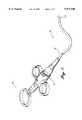
- FIG. 1is a perspective view of a preferred embodiment of a surgical instrument, and particularly an endomyocardial biopsy forceps according to the present invention
- FIG. 2Ais a perspective view of a portion of a handle assembly according to an embodiment of the present invention and for use in the endomyocardial biopsy forceps of FIG. 1;
- FIG. 2Bis an exploded perspective view of the portion of the handle assembly of FIG. 2A;
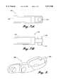
- FIG. 3is a perspective view of a flexible coil and end effector assembly according to an embodiment of the present invention and for use in the endomyocardial biopsy forceps of FIG. 1;
- FIG. 4is an exploded perspective view of the end effector assembly of FIG. 3;
- FIGS. 5A and 5Bare top and side elevation views respectively of a male portion of a housing for use in the end effector assembly of FIGS. 3 and 4;
- FIGS. 6A and 6Bare top and side elevation views respectively of a female portion of a housing for use in the end effector assembly of FIGS. 3 and 4;
- FIGS. 7A and 7Bare side and top elevation views respectively of a distal actuator for use in the end effector assembly of FIGS. 3 and 4;
- FIG. 8is a perspective view of a jaw according to an embodiment of the present invention.
- FIG. 9is a side elevation view of a handle transition according to an embodiment of the present invention and for use in the endomyocardial biopsy forceps of FIG. 1;
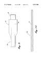
- FIG. 10is a side elevation view of a flexible coil according to an embodiment of the present invention and for use in the endomyocardial biopsy forceps of FIG. 1;
- FIGS. 11A and 11Bare side and top elevation views respectively of a handle body for use in the handle assembly of FIG. 2A;
- FIG. 11Cis a cross-sectional view of the handle body of FIGS. 11A and 11B;
- FIG. 12is a top elevation view of a finger grip for use in the handle assembly of FIG. 2A;
- FIGS. 13A and 13Bare side elevation views of a finger grip insert for use in the handle assembly of FIG. 2A;
- FIG. 14is a top elevation view of a thumb ring for use in the handle assembly of FIG. 2A;
- FIG. 15is a cross-sectional view of a jaw according to the present invention.
- FIG. 16is a diagram of the electrosharpening process according to the present invention.
- the present inventionis directed towards a biopsy forceps device, and a related method, that includes structure for locking the end effectors, typically jaws, in an open position during removal of the tissue sample.
- the proximal actuation handleremains locked in the position corresponding to the open jaw position. In this way, both of the physician's hands may be free from the actuation handle and used to obtain the tissue sample from the jaws.
- the biopsy forceps according to the present inventionalso includes a novel end effector assembly including a split housing to be described in detail herein and jaws that are sharpened and polished at the same time using an electrosharpening chemical process.
- the biopsy forceps deviceis described below and shown in the figures in connection with an endomyocardial biopsy forceps, and particularly a single sample reusable forceps.
- the invention described hereinis fully capable of being incorporated into all biopsy forceps, including multiple sample biopsy forceps, endoscopic biopsy forceps for use in the gastrointestinal tract, urological biopsy forceps for use in the urinary tract, biliary biopsy forceps, and other similar biopsy forceps.
- the invention described hereinmay be used in connection with other types of surgical instruments, such as graspers, that include opposed end effectors other than jaws that move with respect to each other.
- FIG. 1shows an endomyocardial biopsy forceps 10 according to the present invention.
- Biopsy forceps 10includes three main components: a handle 12 at the proximal end of biopsy forceps 10; an end effector assembly 14 at the distal end of biopsy forceps 10; and a long, flexible catheter portion 13 that connects handle 12 to end effector assembly 14.
- handle 12includes a handle body 20, a finger grip 22, a spring 24, a finger grip insert 26, and a thumb ring 44 (see FIG. 1).
- Finger grip 22further includes a hole 32 for insertion of finger grip insert 26, and a slot 34 and a protrusion 36 for providing the locking feature to be described in more detail below.
- Finger grip 22is preferably manufactured by an injection molding process using polycarbonate or other suitable material. Finger grip 22 is generally hollow, as shown in FIG. 2B, to permit passage of handle body 20.
- Handle body 20as most clearly shown in FIGS. 11A to 11C, includes an open slot portion 28, and a groove 38 between a distal nose portion 39 and a stop 40.
- Distal nose portion 39includes a central passageway 42.
- Handle body 20is preferably injection molded from polysulfone or a similar suitable material.
- Thumb ring 44includes a distal portion 46 that inserts into a proximal slot 47 of handle body 20.
- Distal portion 46includes extensions 48 that flex inwardly as they pass through a central passage 49 in handle body 20 between slot 28 and slot 47. Once through passage 49, shoulders 50 of extensions 48 rest against shoulders 52 of handle body portion 20 to restrain thumb ring 44 from its removal from handle body 20.
- Thumb ring 44includes a hole 54 for insertion of the physician's thumb during actuation of the end effector assembly 14.
- Thumb ring 44attaches to handle body 20 so as to permit rotation of thumb ring 44 with respect to handle body 20 so that the physician's thumb may obtain a comfortable position, or orientation, during operation.
- Slot 47 and/or passage 49may include ribs (not shown) to control rotation of thumb ring 44.
- Thumb ring 44is preferably manufactured from an injection molded polycarbonate or other suitable material.
- Finger grip insert 26as most clearly shown in FIGS. 13A and 13B, includes a recessed area 60 leading to a passage 62 that extends through finger grip insert 26.
- a control wire to be described laterinserts within and fixedly attaches to passage 62 in any manner known in the art.
- the connectionis made by an aluminum disk and stainless steel set screw not shown in the drawings.
- Finger grip insert 26inserts into hole 32 of finger grip 22 and is contained within slot 28 of handle body 20. Finger grip insert 26 preferably press fits into finger grip 22 or is otherwise fixedly attached to finger grip 22.
- Spring 24rests between stop 40 of handle body 20 and the inner passageway of finger grip 22 so as to bias finger grip 22 in the proximal direction.
- Flexible catheter portion 13includes a flexible coil 100, as shown in FIGS. 3 and 10.
- An outer sheath 102covers flexible coil 100.
- Flexible coil 100is preferably made of 304 SST steel, and outer sheath 102 is preferably an extruded heat shrunk FEP material or other lubricious material.
- a control wire 103extends through coil 100 and is axially movable with respect to coil 100 to operate end effector assembly 14, as will be described.
- Control wire 103is preferably manufactured from a diamond drawn solid 304 SST steel.
- a liner 110is provided between control wire 103 and coil 100 to lessen the friction force therebetween during respective axial movement. Liner 110 is preferably made of a TFE material or other lubricious material.
- Catheter portion 13connects to handle 12 by a handle transition 104 shown in FIGS. 3 and 9.
- Handle transition 104includes a distal end 105, a proximal end 106, and a centrally located passage 108. Catheter portion 13 extends through passage 108.
- Handle transition 104is crimped or otherwise fixedly attached to catheter portion 13. Crimped handle transition 104 press fits into distal end portion 39 of handle body 20.
- Pull wire 103extends through passage 42 and slot 28 of handle body 20 and connects to finger grip insert 26.
- end effector assembly 14includes a two-piece housing having a female housing portion 150 that connects to a male housing portion 152.
- a distal actuation member 170, links 180, and jaws 190are housed within female and male housings 150 and 152.
- male housing 152includes annular grooves 156 and 160 and a pin 164.
- female housing 150includes annular grooves 154 and 158 corresponding to grooves 156 and 160, and a hole 162 that accepts pin 164.
- Female and male housings 150 and 152are preferably manufactured from 17-4 PH stainless steel. Housings 150 and 152 sandwich together and are laser welded at interface 166 shown in FIG. 3. In addition, pin 164 is welded to hole 162. This differs from many conventional housings in that no fasteners such as rivets are used to hold the end effector assembly together.
- the construction according to the present inventionprovides for an end effector assembly that is lower cost and easier to manufacture and assemble.
- Links 180are preferably manufactured from fully hardened 302 SST steel or other suitably hard material. Fully hardened steel prevents failure of the linkage assembly.
- Flexible coil 100extends into annular grooves 154 and 156 once housings 150 and 152 have been fixedly attached.
- Coli 100preferably has a constant outer diameter, but may include a tapered distal section 112 (FIG. 10) that extends into grooves 154 and 156.
- Coil 100is preferably laser welded to housings 150 and 152 at grooves 154 and 156. Laser welding provides superior strength to conventional methods of soldering or brazing.
- Control wire 103extends from the end of coil 100 and into a passage 172 within member 170. Control wire 103 is preferably laser welded to member 170 at passage 172. As shown in FIGS. 7A and 7B, member 170 further includes pins 174 that extend through holes 182 of links 180 to connect member 170 to links 180.
- Each jaw 190includes an arm 192 having a pin 194 and a hole 196. Each jaw 190 further includes a cup 198 for holding a biopsy tissue sample. Jaws 190 do not include teeth. It is to be understood that jaws of other configurations can be used in accordance with the present invention. For example, saber tooth jaw 200 in FIG. 8 includes teeth 202. With reference to FIG. 4, pins 194 of jaws 190 connect to links 180 at holes 184. Pin 164 of male housing 152 extends through holes 196 into recess 162 of female housing 150.
- jaws 190are machined or metal injection molded from 17-4 PH stainless steel. It is important that the cutting edges of jaws 190 are extremely sharp and burr free so as to cleanly cut tissue samples from the heart with a minimal amount of tearing. According to a preferred manufacturing process, the cutting edges of jaws 190 are sharpened and simultaneously polished using an electrosharpening chemical process. This process has been used conventionally to improve surface finish only (electropolishing). It has been found, however, that this process simultaneously improves surface condition and sharpens edges oriented at a specific angle.
- FIG. 15shows a cross-section of a jaw 190 having an edge 191 machined at a 45 degree angle with respect to a vertical axis y--y.
- the electrosharpening chemical processincludes first cleaning and rinsing the part (jaw) to be sharpened and polished.
- the jawis then processed in a chemical solution placed on a hot plate.
- Direct currentremoves material from the jaw and performs the electrosharpening as a stirrer agitates the solution.
- the jawis then rinsed and dried.
- the electrosharpening chemical processfirst includes ultrasonic cleaning and degreasing a machined jaw.
- the cleaning solutionpreferably includes a mixture of 80% deionized water by volume and 20% by volume of a commercial detergent called "Alternative Cleaner 2000" available from Poly Chem Corporation.
- the cleaning solutionis heated and used at 120 degrees F.
- the beakeris placed in an ultrasonic equipment tank filled with deionized water.
- the jawremains immersed in the mixture for about three to five minutes as ultrasonic energy is used to clean the jaw. Other immersion times, solution temperatures, and solution concentrations may be used depending on the amount of contamination to be removed.
- other suitable detergentsmay be used for the ultrasonic cleaning.
- the jawis then rinsed using a mixture of 50% deionized water by volume and 50% isopropyl alcohol by volume. It is to be understood that other suitable rinsing solutions may be used to rinse the jaws.
- the jawsare preferably rinsed in a plastic cup having a stainless steel screen at the top and numerous small holes at the bottom to permit circulation of the solution. Multiple jaws may be rinsed at one time as long as handling of the jaws is kept to a minimum to ensure that the jaws remain clean. After cleaning and rinsing of the jaw, the jaw is placed in a petri dish lined with a round lint free paper in preparation for the electrosharpening chemical process.
- FIG. 16shows the general set up used in the electrosharpening chemical process.
- the processuses a DC variable Volts/Amps power supply 300 having a digital timer, a hot plate 302 having a stirrer 303, and a beaker 304, preferably a Pyrex 1000 ml beaker.
- a chemical solutionsubstantially fills beaker 304.
- the solutionis preferably a commercial solution of primarily phosphoric acid and glycerine called "Power Clean 500" available from Moletric Corporation. Although the solution has a virtually infinite life, periodic change, for example every 24 hours, is recommended for best results.
- a screen mesh type 304, 303, 316 stainless steel anode 320connects to the negative terminal of the power supply, hangs inside beaker 304, and may be bent to conform to the shape of beaker 304.
- the positive terminal of power supply 300connects to a heavy gold plated clip by a cable 308.
- the clip(not shown) represents the cathode and hangs in the solution during the electrosharpening chemical process.
- a preferable anode/cathode ratio for the processis 100/1, and a preferable current density is 60/100 amps/ft square. The process preferably occurs at room temperature.
- the jawis connected to the gold plated clip so that the cutting edge of the jaw faces anode 320 and is spaced about one inch from the anode.
- the jawis lowered sufficiently into the solution within beaker 304 so that the jaw, and not the gold clip, is sharpened and polished.
- a laboratory jack 306 with a standmay be used to lower the jaw into the solution.
- Stirrer 303 of hot plate 302is set to a suitable level of agitation so that the chemicals do not settle and to promote flow between the cathode and the anode.
- Power supply 300is set to a suitable voltage, preferably 12 volts, and its timer is set to a sufficient amount of time, preferably about 11 seconds.
- a start button of power supply 300is pushed to activate the current and the timer, and the electrosharpening of the jaw takes place. After the set time expires, the jaw is lifted from the solution.
- the jawis rinsed using a mixture of 50% deionized water by volume and 50% isopropyl alcohol by volume, or another suitable rinsing solution, with a separate hot plate and mixer. Thereafter, the jaw is air dried preferably under a fume hood.
- different size jawsmay require adjustments to, for example, the time in the phosphoric acid base solution, the temperature of the hot plate, the type of anode or cathode material, the composition or concentration of the phosphoric acid base solution or rinse solution, the type or amount of agitation, the distance between the anode and the cathode, and other parameters described above. It is also to be understood that the electrosharpening chemical process is applicable for other small parts, especially stainless steel parts with complex geometries, and for parts of other materials, sizes, and complex geometries requiring a sharpness not attainable by conventional methods.
- catheter portion 13is guided through a vein or an artery of a patient until end effector assembly 14 is positioned by a tissue sample site of an interior wall of a heart chamber.
- the physicianthen opens jaws 190 by pushing finger grip 22 in the distal direction. This moves control wire 103 distally relative to coil 100 and pushes member 170 in the distal direction.
- the distal movement of actuator 170forces jaws 190 to open around the tissue to be sampled.
- a sample of the tissueis then cut from the biopsy site by pulling finger grip 22 in the proximal direction to close jaws 190.
- the physicianthen withdraws catheter portion 13 from the patient. During withdrawal, the spring-loaded design keeps jaws 190 closed, ensuring retention of the sample.
- the physicianonce again opens the jaws by pushing finger grip 22 in the distal direction.
- slot 34 of finger grip 22aligns with groove 38 in handle body 20.
- Catheter portion 13may then insert into slot 34 and groove 38.
- the physicianmay then permit finger grip 22 to be biased in the proximal direction by spring 24 until catheter portion 13 is retained within groove 38, against stop 40, and under protrusion 36.
- the compressive force supplied by spring 24retains catheter portion 13 within groove 38.
- Protrusion 36overlies catheter portion 13 to help restrain the release of catheter portion 13 from groove 38.
- finger grip 22is locked in a position so that jaws 190 lock in an open position to retrieve a tissue sample. This permits the physician to remove the tissue sample from jaws 190 without the aid of another person, making sample removal easier and quicker.
Landscapes
- Health & Medical Sciences (AREA)
- Life Sciences & Earth Sciences (AREA)
- Surgery (AREA)
- Heart & Thoracic Surgery (AREA)
- Nuclear Medicine, Radiotherapy & Molecular Imaging (AREA)
- Pathology (AREA)
- Engineering & Computer Science (AREA)
- Biomedical Technology (AREA)
- Biodiversity & Conservation Biology (AREA)
- Medical Informatics (AREA)
- Molecular Biology (AREA)
- Animal Behavior & Ethology (AREA)
- General Health & Medical Sciences (AREA)
- Public Health (AREA)
- Veterinary Medicine (AREA)
- Surgical Instruments (AREA)
Abstract
Description
Claims (30)
Priority Applications (1)
| Application Number | Priority Date | Filing Date | Title |
|---|---|---|---|
| US09/027,483US5971940A (en) | 1998-02-20 | 1998-02-20 | Surgical instrument with locking feature, split distal housing, and sharpened jaws |
Applications Claiming Priority (1)
| Application Number | Priority Date | Filing Date | Title |
|---|---|---|---|
| US09/027,483US5971940A (en) | 1998-02-20 | 1998-02-20 | Surgical instrument with locking feature, split distal housing, and sharpened jaws |
Publications (1)
| Publication Number | Publication Date |
|---|---|
| US5971940Atrue US5971940A (en) | 1999-10-26 |
Family
ID=21837993
Family Applications (1)
| Application Number | Title | Priority Date | Filing Date |
|---|---|---|---|
| US09/027,483Expired - LifetimeUS5971940A (en) | 1998-02-20 | 1998-02-20 | Surgical instrument with locking feature, split distal housing, and sharpened jaws |
Country Status (1)
| Country | Link |
|---|---|
| US (1) | US5971940A (en) |
Cited By (27)
| Publication number | Priority date | Publication date | Assignee | Title |
|---|---|---|---|---|
| USD478987S1 (en) | 2002-04-05 | 2003-08-26 | Allegiance Corporation | Biopsy device |
| US20030212343A1 (en)* | 2002-04-05 | 2003-11-13 | Michael Plishka | Biopsy needle and biopsy device containing the same |
| US20040059186A1 (en)* | 2002-09-19 | 2004-03-25 | Amnon Weichselbaum | Insemination device |
| US20050124912A1 (en)* | 2003-12-05 | 2005-06-09 | Scimed Life Systems, Inc. | Medical device with deflecting shaft and related methods of manufacture and use |
| US20050159728A1 (en)* | 2004-01-15 | 2005-07-21 | Thomas Medical Products, Inc. | Steerable sheath |
| US7037276B2 (en) | 2002-07-02 | 2006-05-02 | Precision Medical Devices, Inc. | Biopsy device |
| US20060178699A1 (en)* | 2005-01-20 | 2006-08-10 | Wilson-Cook Medical Inc. | Biopsy forceps |
| US20060184198A1 (en)* | 2005-01-31 | 2006-08-17 | Kms Biopsy, Llc | End effector for surgical instrument, surgical instrument, and method for forming the end effector |
| US7118586B1 (en) | 1999-10-25 | 2006-10-10 | Boston Scientific Scimed, Inc. | Forceps for medical use |
| US20070213634A1 (en)* | 2006-02-24 | 2007-09-13 | Boston Scientific Scimed, Inc. | Obtaining a tissue sample |
| US20070250112A1 (en)* | 2006-03-13 | 2007-10-25 | Sundaram Ravikumar | Minimally Invasive Surgical Assembly and Methods |
| US7588545B2 (en) | 2003-09-10 | 2009-09-15 | Boston Scientific Scimed, Inc. | Forceps and collection assembly with accompanying mechanisms and related methods of use |
| US20090287113A1 (en)* | 2008-05-13 | 2009-11-19 | Ken Freeman | Reusable biopsy forceps |
| US20090287112A1 (en)* | 2008-05-13 | 2009-11-19 | Ken Freeman | Biopsy forceps with hold open jaw feature |
| US7762960B2 (en) | 2005-05-13 | 2010-07-27 | Boston Scientific Scimed, Inc. | Biopsy forceps assemblies |
| US7857827B2 (en) | 2006-04-14 | 2010-12-28 | Ethicon Endo-Surgery, Inc. | Endoscopic device |
| US7942896B2 (en) | 2003-11-25 | 2011-05-17 | Scimed Life Systems, Inc. | Forceps and collection assembly and related methods of use and manufacture |
| US7998167B2 (en) | 2006-04-14 | 2011-08-16 | Ethicon Endo-Surgery, Inc. | End effector and method of manufacture |
| US8313500B2 (en) | 2006-04-14 | 2012-11-20 | Ethicon Endo-Surgery, Inc. | Endoscopic device |
| US8523899B2 (en)* | 2010-12-28 | 2013-09-03 | Olympus Medical Systems Corp. | Treatment device for endoscope |
| WO2013142810A3 (en)* | 2012-03-22 | 2013-11-14 | Rafic Saleh | Surgical instrument for deep tissue and/or cell sampling |
| US20140336456A1 (en)* | 2013-03-15 | 2014-11-13 | Research & Development International Inc. | Method and apparatus for steerable, rotatable, microendoscope with tool for cutting, coagulating, desiccating and fulgurating tissue |
| USD871673S1 (en) | 2017-12-15 | 2019-12-31 | Tixodes LLC | Tweezer with scoop tips |
| CN111000595A (en)* | 2019-12-27 | 2020-04-14 | 安徽医科大学第二附属医院 | Cervical canal tissue sampler |
| CN112971869A (en)* | 2020-07-08 | 2021-06-18 | 郑州大学第一附属医院 | Peripheral telescopic forceps flap type multifunctional cavity biopsy forceps device |
| EP4193945A1 (en)* | 2021-12-09 | 2023-06-14 | Karl Storz SE & Co. KG | Surgical instrument and method connecting device |
| US11944335B2 (en) | 2019-05-20 | 2024-04-02 | Boston Scientific Medical Device Limited | Endoscopic medical device and method of use |
Citations (15)
| Publication number | Priority date | Publication date | Assignee | Title |
|---|---|---|---|---|
| US4815476A (en)* | 1988-03-28 | 1989-03-28 | Cordis Corporation | Biopsy forceps with locking handle |
| US4887612A (en)* | 1988-04-27 | 1989-12-19 | Esco Precision, Inc. | Endoscopic biopsy forceps |
| US5147380A (en)* | 1991-10-03 | 1992-09-15 | Cordis Corporation | Biopsy forceps device having improved locking means |
| US5184625A (en)* | 1992-04-16 | 1993-02-09 | Cordis Corporation | Biopsy forceps device having improved handle |
| US5251638A (en)* | 1992-04-16 | 1993-10-12 | Cordis Corporation | Biopsy forceps device having improved handle assembly |
| US5391180A (en)* | 1991-08-05 | 1995-02-21 | United States Surgical Corporation | Articulating endoscopic surgical apparatus |
| US5431675A (en)* | 1992-09-23 | 1995-07-11 | United States Surgical Corporation | Locking mechanism for endoscopic or laparoscopic surgical instruments |
| US5476099A (en)* | 1994-08-31 | 1995-12-19 | Boston Scientific Corporation | High velocity tissue sample cutter |
| US5490861A (en)* | 1994-07-14 | 1996-02-13 | Symbiosis Corporation | Track guided end effector assembly for use with endoscopic instruments |
| US5496317A (en)* | 1993-05-04 | 1996-03-05 | Gyrus Medical Limited | Laparoscopic surgical instrument |
| US5507773A (en)* | 1994-02-18 | 1996-04-16 | Ethicon Endo-Surgery | Cable-actuated jaw assembly for surgical instruments |
| US5611808A (en)* | 1995-09-12 | 1997-03-18 | Cabot Technology Corporation | Blade assembly receptacle and method |
| US5620459A (en)* | 1992-04-15 | 1997-04-15 | Microsurge, Inc. | Surgical instrument |
| US5626597A (en)* | 1995-02-21 | 1997-05-06 | United States Surgical Corporation | Percutaneous introducer |
| US5667526A (en)* | 1995-09-07 | 1997-09-16 | Levin; John M. | Tissue retaining clamp |
- 1998
- 1998-02-20USUS09/027,483patent/US5971940A/ennot_activeExpired - Lifetime
Patent Citations (16)
| Publication number | Priority date | Publication date | Assignee | Title |
|---|---|---|---|---|
| US4815476A (en)* | 1988-03-28 | 1989-03-28 | Cordis Corporation | Biopsy forceps with locking handle |
| US4887612A (en)* | 1988-04-27 | 1989-12-19 | Esco Precision, Inc. | Endoscopic biopsy forceps |
| US5391180A (en)* | 1991-08-05 | 1995-02-21 | United States Surgical Corporation | Articulating endoscopic surgical apparatus |
| US5147380A (en)* | 1991-10-03 | 1992-09-15 | Cordis Corporation | Biopsy forceps device having improved locking means |
| US5620459A (en)* | 1992-04-15 | 1997-04-15 | Microsurge, Inc. | Surgical instrument |
| US5184625A (en)* | 1992-04-16 | 1993-02-09 | Cordis Corporation | Biopsy forceps device having improved handle |
| US5251638A (en)* | 1992-04-16 | 1993-10-12 | Cordis Corporation | Biopsy forceps device having improved handle assembly |
| US5431675A (en)* | 1992-09-23 | 1995-07-11 | United States Surgical Corporation | Locking mechanism for endoscopic or laparoscopic surgical instruments |
| US5496317A (en)* | 1993-05-04 | 1996-03-05 | Gyrus Medical Limited | Laparoscopic surgical instrument |
| US5562700A (en)* | 1994-02-18 | 1996-10-08 | Ethicon Endo-Surgery, Inc. | Cable-actuated jaw assembly for surgical instruments |
| US5507773A (en)* | 1994-02-18 | 1996-04-16 | Ethicon Endo-Surgery | Cable-actuated jaw assembly for surgical instruments |
| US5490861A (en)* | 1994-07-14 | 1996-02-13 | Symbiosis Corporation | Track guided end effector assembly for use with endoscopic instruments |
| US5476099A (en)* | 1994-08-31 | 1995-12-19 | Boston Scientific Corporation | High velocity tissue sample cutter |
| US5626597A (en)* | 1995-02-21 | 1997-05-06 | United States Surgical Corporation | Percutaneous introducer |
| US5667526A (en)* | 1995-09-07 | 1997-09-16 | Levin; John M. | Tissue retaining clamp |
| US5611808A (en)* | 1995-09-12 | 1997-03-18 | Cabot Technology Corporation | Blade assembly receptacle and method |
Non-Patent Citations (10)
| Title |
|---|
| "BYCEP Single-Use Endomyocardial Biopsy Forceps" marketing materials, EP Technologies, 5 pages 1996. |
| "Disposable Biopsy Forceps" marketing materials, Cook Incorporated, 5 pages 1989. |
| "Disposable Cordis Biopsy Forceps" marketing materials, Cordis Corporation, 13 pages 1988. |
| "Endomyocardial Biopsy Forcep" marketing materials, ARGON Medical, 4 pages 1992. |
| "FEHLING Bioptome System" marketing materials, INRAD, 8 pages 1987. |
| BYCEP Single Use Endomyocardial Biopsy Forceps marketing materials, EP Technologies, 5 pages 1996.* |
| Disposable Biopsy Forceps marketing materials, Cook Incorporated, 5 pages 1989.* |
| Disposable Cordis Biopsy Forceps marketing materials, Cordis Corporation, 13 pages 1988.* |
| Endomyocardial Biopsy Forcep marketing materials, ARGON Medical, 4 pages 1992.* |
| FEHLING Bioptome System marketing materials, INRAD, 8 pages 1987.* |
Cited By (46)
| Publication number | Priority date | Publication date | Assignee | Title |
|---|---|---|---|---|
| US7909850B2 (en) | 1999-10-25 | 2011-03-22 | Boston Scientific Scimed, Inc. | Forceps for medical use |
| US7118586B1 (en) | 1999-10-25 | 2006-10-10 | Boston Scientific Scimed, Inc. | Forceps for medical use |
| USD478987S1 (en) | 2002-04-05 | 2003-08-26 | Allegiance Corporation | Biopsy device |
| US20030212343A1 (en)* | 2002-04-05 | 2003-11-13 | Michael Plishka | Biopsy needle and biopsy device containing the same |
| US7018343B2 (en) | 2002-04-05 | 2006-03-28 | Allegiance Corporation | Biopsy needle and biopsy device containing the same |
| US7037276B2 (en) | 2002-07-02 | 2006-05-02 | Precision Medical Devices, Inc. | Biopsy device |
| US20040059186A1 (en)* | 2002-09-19 | 2004-03-25 | Amnon Weichselbaum | Insemination device |
| US8460205B2 (en) | 2003-09-10 | 2013-06-11 | Boston Scientific Scimed, Inc. | Forceps and collection assembly with accompanying mechanisms and related methods of use |
| US8083686B2 (en) | 2003-09-10 | 2011-12-27 | Boston Scientific Scimed, Inc. | Forceps and collection assembly with accompanying mechanisms and related methods of use |
| US7588545B2 (en) | 2003-09-10 | 2009-09-15 | Boston Scientific Scimed, Inc. | Forceps and collection assembly with accompanying mechanisms and related methods of use |
| US7942896B2 (en) | 2003-11-25 | 2011-05-17 | Scimed Life Systems, Inc. | Forceps and collection assembly and related methods of use and manufacture |
| US20060206145A1 (en)* | 2003-12-05 | 2006-09-14 | Boston Scientific Scimed, Inc. | Medical device with deflecting shaft and related methods of manufacture and use |
| WO2005060841A1 (en)* | 2003-12-05 | 2005-07-07 | Boston Scientific Limited | Medical device with deflecting shaft and related methods of manufacture and use |
| US20050124912A1 (en)* | 2003-12-05 | 2005-06-09 | Scimed Life Systems, Inc. | Medical device with deflecting shaft and related methods of manufacture and use |
| US7052489B2 (en) | 2003-12-05 | 2006-05-30 | Scimed Life Systems, Inc. | Medical device with deflecting shaft and related methods of manufacture and use |
| US20050159728A1 (en)* | 2004-01-15 | 2005-07-21 | Thomas Medical Products, Inc. | Steerable sheath |
| US20060178699A1 (en)* | 2005-01-20 | 2006-08-10 | Wilson-Cook Medical Inc. | Biopsy forceps |
| US20060184198A1 (en)* | 2005-01-31 | 2006-08-17 | Kms Biopsy, Llc | End effector for surgical instrument, surgical instrument, and method for forming the end effector |
| US8672859B2 (en) | 2005-05-13 | 2014-03-18 | Boston Scientific Scimed, Inc. | Biopsy forceps assemblies |
| US7762960B2 (en) | 2005-05-13 | 2010-07-27 | Boston Scientific Scimed, Inc. | Biopsy forceps assemblies |
| US8317726B2 (en) | 2005-05-13 | 2012-11-27 | Boston Scientific Scimed, Inc. | Biopsy forceps assemblies |
| US20070213634A1 (en)* | 2006-02-24 | 2007-09-13 | Boston Scientific Scimed, Inc. | Obtaining a tissue sample |
| US7473232B2 (en) | 2006-02-24 | 2009-01-06 | Boston Scientific Scimed, Inc. | Obtaining a tissue sample |
| US7828746B2 (en) | 2006-02-24 | 2010-11-09 | Boston Scientific Scimed, Inc. | Obtaining a tissue sample |
| US9492187B2 (en)* | 2006-03-13 | 2016-11-15 | Teleflex Medical Incorporated | Minimally invasive surgical assembly and methods |
| US11109875B2 (en) | 2006-03-13 | 2021-09-07 | Teleflex Medical Incorporated | Minimally invasive surgical assembly and methods |
| US10166038B2 (en) | 2006-03-13 | 2019-01-01 | Teleflex Medical Incorporated | Minimally invasive surgical assembly and methods |
| US20070250112A1 (en)* | 2006-03-13 | 2007-10-25 | Sundaram Ravikumar | Minimally Invasive Surgical Assembly and Methods |
| US8740853B2 (en) | 2006-04-14 | 2014-06-03 | Ethicon Endo-Surgery, Inc. | Endoscopic device and method of packaging |
| US7857827B2 (en) | 2006-04-14 | 2010-12-28 | Ethicon Endo-Surgery, Inc. | Endoscopic device |
| US8313500B2 (en) | 2006-04-14 | 2012-11-20 | Ethicon Endo-Surgery, Inc. | Endoscopic device |
| US7998167B2 (en) | 2006-04-14 | 2011-08-16 | Ethicon Endo-Surgery, Inc. | End effector and method of manufacture |
| US20090287112A1 (en)* | 2008-05-13 | 2009-11-19 | Ken Freeman | Biopsy forceps with hold open jaw feature |
| US20090287113A1 (en)* | 2008-05-13 | 2009-11-19 | Ken Freeman | Reusable biopsy forceps |
| US8025626B2 (en)* | 2008-05-13 | 2011-09-27 | Ken Freeman | Biopsy forceps with hold open jaw feature |
| US8025627B2 (en)* | 2008-05-13 | 2011-09-27 | Ken Freeman | Reusable biopsy forceps |
| US8523899B2 (en)* | 2010-12-28 | 2013-09-03 | Olympus Medical Systems Corp. | Treatment device for endoscope |
| WO2013142810A3 (en)* | 2012-03-22 | 2013-11-14 | Rafic Saleh | Surgical instrument for deep tissue and/or cell sampling |
| US20140336456A1 (en)* | 2013-03-15 | 2014-11-13 | Research & Development International Inc. | Method and apparatus for steerable, rotatable, microendoscope with tool for cutting, coagulating, desiccating and fulgurating tissue |
| USD871673S1 (en) | 2017-12-15 | 2019-12-31 | Tixodes LLC | Tweezer with scoop tips |
| USD937486S1 (en) | 2017-12-15 | 2021-11-30 | Tixodes, Llc | Tweezer with scoop tips |
| US11944335B2 (en) | 2019-05-20 | 2024-04-02 | Boston Scientific Medical Device Limited | Endoscopic medical device and method of use |
| CN111000595A (en)* | 2019-12-27 | 2020-04-14 | 安徽医科大学第二附属医院 | Cervical canal tissue sampler |
| CN112971869A (en)* | 2020-07-08 | 2021-06-18 | 郑州大学第一附属医院 | Peripheral telescopic forceps flap type multifunctional cavity biopsy forceps device |
| CN112971869B (en)* | 2020-07-08 | 2023-08-08 | 郑州大学第一附属医院 | Circumferentially telescopic forceps flap type multifunctional lumen biopsy forceps device |
| EP4193945A1 (en)* | 2021-12-09 | 2023-06-14 | Karl Storz SE & Co. KG | Surgical instrument and method connecting device |
Similar Documents
| Publication | Publication Date | Title |
|---|---|---|
| US5971940A (en) | Surgical instrument with locking feature, split distal housing, and sharpened jaws | |
| JP5020942B2 (en) | Biopsy forceps assembly | |
| US6159162A (en) | Biopsy apparatus | |
| US6110127A (en) | Medical instrument for use in combination with an endoscope | |
| US6273860B1 (en) | Biopsy apparatus | |
| US5746216A (en) | Endoscopic multiple sample bioptome with enhanced biting action | |
| EP0843533B1 (en) | Endoscopic multiple sample bioptome | |
| US5947996A (en) | Yoke for surgical instrument | |
| JP4094677B2 (en) | Biopsy forceps with removable handle and distal jaw | |
| US8460205B2 (en) | Forceps and collection assembly with accompanying mechanisms and related methods of use | |
| CN102821706B (en) | Follicular unit removal tool with pivoting retaining member | |
| JPH06502779A (en) | Surgical tubular cutting instrument | |
| WO2001087166A2 (en) | Medical device handle | |
| DE10114940C2 (en) | Forceps for an endoscope and manufacturing method for forceps | |
| US9770254B2 (en) | Flat object grasper | |
| US20050137585A1 (en) | Back loading endoscopic instruments | |
| US20050113867A1 (en) | Forceps and collection assembly and related methods of use and manufacture | |
| WO1995008944A2 (en) | Multiple biopsy sampling forceps | |
| JP2002263110A (en) | Forceps for endoscope | |
| JPH08238245A (en) | Sampling blade structure for treating device for endoscope | |
| JP2006314519A (en) | Forceps |
Legal Events
| Date | Code | Title | Description |
|---|---|---|---|
| AS | Assignment | Owner name:BOSTON SCIENTIFIC CORPORATION, MASSACHUSETTS Free format text:ASSIGNMENT OF ASSIGNORS INTEREST;ASSIGNORS:BAKER, ERIC;CRAN, BRIAN;PLAIA, MARK E.;AND OTHERS;REEL/FRAME:009073/0060 Effective date:19980219 | |
| AS | Assignment | Owner name:SCIMED LIFE SYSTEMS, INC., MINNESOTA Free format text:ASSIGNMENT OF ASSIGNORS INTEREST;ASSIGNOR:BOSTON SCIENTIFIC CORPORATION;REEL/FRAME:010165/0717 Effective date:19990804 | |
| STCF | Information on status: patent grant | Free format text:PATENTED CASE | |
| FPAY | Fee payment | Year of fee payment:4 | |
| AS | Assignment | Owner name:BOSTON SCIENTIFIC SCIMED, INC., MINNESOTA Free format text:CHANGE OF NAME;ASSIGNOR:SCIMED LIFE SYSTEMS, INC.;REEL/FRAME:018505/0868 Effective date:20050101 Owner name:BOSTON SCIENTIFIC SCIMED, INC.,MINNESOTA Free format text:CHANGE OF NAME;ASSIGNOR:SCIMED LIFE SYSTEMS, INC.;REEL/FRAME:018505/0868 Effective date:20050101 | |
| FPAY | Fee payment | Year of fee payment:8 | |
| CC | Certificate of correction | ||
| FPAY | Fee payment | Year of fee payment:12 |