US5971938A - Access device with expandable containment member - Google Patents
Access device with expandable containment memberDownload PDFInfo
- Publication number
- US5971938A US5971938AUS08/974,300US97430097AUS5971938AUS 5971938 AUS5971938 AUS 5971938AUS 97430097 AUS97430097 AUS 97430097AUS 5971938 AUS5971938 AUS 5971938A
- Authority
- US
- United States
- Prior art keywords
- containment member
- access device
- expandable
- obturator
- distal
- Prior art date
- Legal status (The legal status is an assumption and is not a legal conclusion. Google has not performed a legal analysis and makes no representation as to the accuracy of the status listed.)
- Expired - Lifetime
Links
- 230000002441reversible effectEffects0.000claimsdescription17
- 230000006835compressionEffects0.000claimsdescription6
- 238000007906compressionMethods0.000claimsdescription6
- 239000006185dispersionSubstances0.000claimsdescription5
- 238000003780insertionMethods0.000abstractdescription17
- 230000037431insertionEffects0.000abstractdescription17
- 230000015572biosynthetic processEffects0.000abstractdescription2
- 239000000463materialSubstances0.000description45
- 239000007787solidSubstances0.000description16
- 238000000034methodMethods0.000description13
- 210000004204blood vesselAnatomy0.000description11
- 230000001225therapeutic effectEffects0.000description11
- 238000005452bendingMethods0.000description9
- 230000008878couplingEffects0.000description6
- 238000010168coupling processMethods0.000description6
- 238000005859coupling reactionMethods0.000description6
- 230000006870functionEffects0.000description5
- 230000008901benefitEffects0.000description4
- 230000004927fusionEffects0.000description4
- 210000003813thumbAnatomy0.000description4
- 208000005189EmbolismDiseases0.000description3
- 208000007536ThrombosisDiseases0.000description3
- 238000013156embolectomyMethods0.000description3
- 230000009466transformationEffects0.000description3
- 239000008280bloodSubstances0.000description2
- 210000004369bloodAnatomy0.000description2
- 238000010276constructionMethods0.000description2
- 239000013536elastomeric materialSubstances0.000description2
- 210000003811fingerAnatomy0.000description2
- 230000007246mechanismEffects0.000description2
- 230000005012migrationEffects0.000description2
- 238000013508migrationMethods0.000description2
- 238000003825pressingMethods0.000description2
- 230000008569processEffects0.000description2
- 239000003351stiffenerSubstances0.000description2
- 238000013151thrombectomyMethods0.000description2
- 230000032258transportEffects0.000description2
- 230000000472traumatic effectEffects0.000description2
- 208000031481Pathologic ConstrictionDiseases0.000description1
- 208000002847Surgical WoundDiseases0.000description1
- 230000009471actionEffects0.000description1
- 230000001154acute effectEffects0.000description1
- 238000010420art techniqueMethods0.000description1
- 230000004888barrier functionEffects0.000description1
- 230000008859changeEffects0.000description1
- 239000011248coating agentSubstances0.000description1
- 238000000576coating methodMethods0.000description1
- 239000002131composite materialSubstances0.000description1
- 238000000502dialysisMethods0.000description1
- 238000012377drug deliveryMethods0.000description1
- 230000009977dual effectEffects0.000description1
- 239000012530fluidSubstances0.000description1
- 238000010438heat treatmentMethods0.000description1
- 208000014674injuryDiseases0.000description1
- 238000005304joiningMethods0.000description1
- 238000004519manufacturing processMethods0.000description1
- 230000004048modificationEffects0.000description1
- 238000012986modificationMethods0.000description1
- 229920001296polysiloxanePolymers0.000description1
- 238000004904shorteningMethods0.000description1
- 229920005573silicon-containing polymerPolymers0.000description1
- 230000002966stenotic effectEffects0.000description1
- 238000006467substitution reactionMethods0.000description1
- 230000007704transitionEffects0.000description1
- 230000008733traumaEffects0.000description1
Images


Classifications
- A—HUMAN NECESSITIES
- A61—MEDICAL OR VETERINARY SCIENCE; HYGIENE
- A61B—DIAGNOSIS; SURGERY; IDENTIFICATION
- A61B17/00—Surgical instruments, devices or methods
- A61B17/22—Implements for squeezing-off ulcers or the like on inner organs of the body; Implements for scraping-out cavities of body organs, e.g. bones; for invasive removal or destruction of calculus using mechanical vibrations; for removing obstructions in blood vessels, not otherwise provided for
- A61B17/22031—Gripping instruments, e.g. forceps, for removing or smashing calculi
Definitions
- the present inventionrelates generally to devices for removing obstructing material from body passages and, more particularly, to an access device configurable between a first small diameter for initial insertion into a body passage and a second larger diameter for effecting the removal of obstructing material.
- obstructing materialsmay include plaque, thrombus, embolus, clots, and fatty deposits. In other cases, obstructions may result from stones and strictures.
- Cathetersare commonly inserted into vessels for the purpose of dislodging obstructing materials from the vessel walls.
- a balloon tipped catheteris introduced through a surgical incision and into a blood vessel.
- the balloon tipped catheteris advanced to the location of the obstructing material or occlusion, and the balloon is then inflated at a point within the vessel beyond the point of the obstructing material.
- the catheter including the attached balloonis then pulled back to the point of insertion. In this manner, the balloon pushes the obstructing material to the point of insertion where it is removed through the incision.
- a problem associated with this embolectomy techniqueinvolves the efficient collection and removal of obstructing material while preventing migration and dispersion of the obstructing material.
- Other percutaneous proceduresexist in the prior art for recanalization of vessels.
- One percutaneous procedureinvolves the use of laser energy to vaporize the stenotic material.
- Another percutaneous procedurecommonly referred to as aspiration embolectomy/thrombectomy, relies on a negative pressure to collect the obstructing material.
- Percutaneous or minimally invasive access to a blood vessel in the case of a balloon catheterrequires the catheter to have a very small diameter to fit through a corresponding small incision in the blood vessel. Once the catheter is in the blood vessel, however, portions of the catheter need to assume a large profile removal interface for efficient removal of the obstructing material from the lumen of the blood vessel.
- U.S. Pat. No. 5,011,488 to Ginsburgdiscloses the use of an expanding funnel-shaped sheath for use in withdrawing thrombus or embolus (obstructing material) from a blood vessel.
- the funnelis deployed by extending the expanding funnel-shaped sheath from within a second sheath to thereby allow the compressed funnel to expand radially.
- Use of this second sheathtends to increase the overall diameter of the device, thus increasing the size of the incision required for insertion of the device.
- this deviceIn addition to not achieving an optimally small insertion diameter, this device is also unable to obtain an optimally large intraluminal operating diameter. An optimally large intraluminal operating diameter would allow for better insertion and removal of larger instruments through the sheath.
- This prior art technique of inserting both the introducer sheath and the pre-shaped funnel sheath into the body passage, and of subsequently removing the introducer sheathrequires the large introduction incision to form a seal around the smaller diameter pre-shaped funnel sheath after the introducer sheath is removed.
- the double sheath combination of the prior artrequires an initial incision into the body passage large enough to accommodate the introducer sheath and, subsequently, small enough to adequately form a seal around the smaller pre-formed funnel sheath left in place after the introducer sheath is removed. Since the initial incision cannot be subsequently reduced in size to accommodate the funnel sheath, a good seal in this prior art system is difficult to obtain.
- U.S. Pat. No. 5,234,425 to Fogartydiscloses a variable diameter sheath constructed of a composite elastomeric material that may be stretched to reduce the diameter. This variable diameter sheath, however, is not used for the removal of obstructing material.
- the primary goal of this deviceis to provide a lining of a body passage with a thin walled single thickness interior sheath, which is introduced into the body passage in a reduced diameter condition and subsequently expanded to snugly fit the interior wall of the body passage.
- the variable diameter sheathincorporates a tubular braid encapsulated within a coating of high elongation silicone polymer.
- the access device of the present inventiondoes not require an initial large incision to subsequently form a seal around a smaller-diameter funnel-shaped sheath. Rather, the access device of the present invention is insertable into a body passage or duct using a minimally invasive technique.
- a distal portion of the access device of the present inventionis operable to enlarge in diameter, while the diameter of the portion contacting the incision area of the blood vessel remains constant.
- the access devicefits through an optimally small incision within the blood vessel, and the portion of the access device contacting the incision area of the blood vessel does not change in diameter, thus providing an effective seal.
- the enlargeable diameter of the distal portion of the access devicemay comprise any of a variety of predetermined shapes and sizes, depending upon the specific needs required by a given procedure.
- the distal end of the access devicemay assume the shape of a forward facing funnel to provide a mechanism for withdrawing obstructing material from the body passage.
- a single sheath having an optimally minimum diameteris inserted through an incision in a body passage.
- the single sheath of the access deviceis inserted into the body passage incision with the expandable containment member of the access device in a minimum diameter configuration.
- the expandable containment memberis held in the minimum diameter configuration using structure other than the large-diameter external sheath of the prior art.
- the structure used by the present invention for configuring the expandable containment member to a minimum diametercan subsequently be removed from the lumen of the access device, once the expandable containment member has been expanded.
- the mechanism for configuring the expandable containment memberdoes not increase the outside diameter of the access device. When the structure for configuring the expandable containment member in the small diameter configuration is no longer needed, it can be removed from the body passage without affecting the outside diameter of the access device near the incision in the body passage.
- the access deviceincludes an outer tube having a proximal tube end and a distal tube end, and a lumen extending between the proximal tube end and the distal tube end.
- An obturator assemblyhaving a proximal obturator end and a distal obturator end is removably and concentrically disposed within the lumen of the outer tube.
- An expandable containment memberhaving a proximal member end and a distal member end is connected to both the distal tube end and the distal obturator end. The proximal member end is connected to the distal tube end, and the distal member end is detachably connected to the distal obturator end.
- the expandable containment membercan be expanded by relative movement between the proximal member end and the distal member end. This relative movement corresponds to relative movement of the outer tube and the obturator assembly in opposite directions.
- the proximal member end of the expandable containment memberis held away from the distal member end of the expandable containment member, to thereby hold the expandable containment member in an unexpanded state.
- the proximal member end and the distal member endare moved together to expand the expandable containment member.
- the obturator assemblycan then be removed from the access device, to thereby provide an unobstructed lumen within the outer tube.
- the lumen of the outer tubecan then facilitate insertion and removal of instruments and materials.
- a therapeutic balloon cathetercan be inserted into the lumen to facilitate removal of embolus or thrombus.
- the access device of the present inventionfurther includes a guidewire, which is adapted to be inserted through the obturator assembly.
- the guidewireacts as a stiffener and as a leader for the access device.
- the outer tube of the access devicehas a predetermined outer diameter and an axis extending between the proximal tube end and the distal tube end.
- the expandable containment memberis attached to the outer tube at the distal tube end, and has an unexpanded diameter that is proximally equal to the outer diameter of the outer tube.
- the outer tubemay include a solid walled tubular member, and the expandable containment member may include a braided tubular component.
- the solid walled tubular member and the expandable containment memberare joined together by bonding or fusion, and the expandable containment member may be coated with a non-permeable elastomeric material that forms a barrier to flow within the body passage when the expandable containment member is expanded.
- the obturator assembly of the present inventionis initially connected to the expandable containment member to facilitate insertion of the access device into the body passage.
- the obturator assemblyis disconnected from this expandable containment member after insertion of the access device, to thereby facilitate movement of the obturator assembly within the expandable containment member.
- the obturator assembly of the present inventionincludes an intermediate slidable obturator sleeve having a proximal intermediate sleeve end and a distal intermediate sleeve end.
- a lumenextends between the proximal intermediate sleeve end and the distal intermediate sleeve end.
- An inner fixed obturator sleevehas a proximal inner sleeve end and a distal inner sleeve end, and is concentrically disposed within the lumen of the intermediate slidable obturator sleeve.
- the obturatorfurther includes an obturator expandable cone, which has a proximal cone end and a distal cone end. The distal cone end is connected to the distal inner sleeve end, and the proximal cone end is connected to the distal intermediate sleeve end.
- the obturator expandable conecan be expanded by relative movement between the proximal cone end and the distal cone end, which is affected by relative movement of the distal inner sleeve end and the distal intermediate sleeve end in opposite directions.
- the obturator expandable coneOnce the obturator expandable cone has been expanded, the obturator is moved proximally against the expandable containment member, to thereby compress the expandable containment member about an axis of the expandable containment member.
- the expandable containment memberbends about a mid-point of the expandable containment member located between the proximal member end and the distal member end.
- the expandable containment memberforms a cone when the proximal member end is moved sufficiently close to the distal member end, and when the distal member end is moved proximally past the midpoint of the expandable containment member.
- a tubular access deviceis inserted into the body passage, and the tubular access device is moved in a distal direction within the body passage to a first location where obstructing material is located within the body passage.
- the distal end of the expandable containment memberis moved toward the proximal end of the expandable containment member, to thereby expand the expandable containment member into a cone shape having a relatively large diameter.
- the obturator assembly of the access deviceis removed from the lumen of the outer tube, and a therapeutic catheter is inserted into the outer tube, and moved in the distal direction past the first location within the body passage, to a second location on the distal side of the obstructing material.
- the therapeutic catheteris expanded, and is then retracted in a proximal direction from the second location toward the expandable containment member. Movement of the expanded therapeutic catheter in the proximal direction transports the obstructing material into the expandable containment member and then into the lumen of the outer tube.
- the obturator assemblyis inserted back into the lumen of the outer tube and used to collapse the expandable containment member into a low-diameter configuration.
- the access deviceis then removed from the body passage with the expandable containment member in the low-profile configuration.
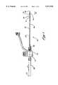
- FIG. 1is a side view of the assembled access device according to the presently preferred embodiment
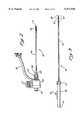
- FIG. 2is a side view of the sheath assembly according to the presently preferred embodiment
- FIG. 3is a side view of the obturator assembly according to the presently preferred embodiment
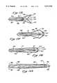
- FIG. 4is a cross-sectional view of the access device in the introductory profile and unexpanded condition according to the presently preferred embodiment
- FIG. 5is a cross-sectional view of the deployed access device showing the obturator expandable cone expanding the expandable containment member of the access device according to the presently preferred embodiment
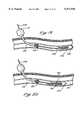
- FIG. 6is a cross-sectional view of the deployed access device showing the obturator expandable cone in an unexpanded condition according to the presently preferred embodiment
- FIG. 7is a view of access device with the obturator removed and with the expandable containment member fully deployed according to the presently preferred embodiment
- FIG. 8is a side view of the access device with the obturator assembly removed and the expandable containment member deployed;
- FIG. 9is a cross-sectional view of a first alternative embodiment of the present invention in the introductory profile
- FIG. 10is a cross-sectional view of the first alternative embodiment of the present invention showing the expandable containment member partially deployed;
- FIG. 11is a cross-sectional view of the first alternative embodiment of the present invention showing the expandable containment member fully deployed;
- FIG. 12is a cross-sectional view of the first alternative embodiment of the present invention with the obturator assembly removed and the expandable containment member fully deployed;
- FIGS. 13A-Gare axial cross-section views of a second alternative embodiment of the present invention illustrating the sequence of expansion and deployment;
- FIGS. 14A-Dare axial cross-section views of a third alternative embodiment of the present invention showing the sequence of deployment of the expandable containment member
- FIG. 15is a view of the presently preferred embodiment inserted within a body passage
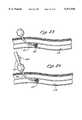
- FIG. 16is a view of the presently preferred embodiment inserted within a body passage with the obturator expandable cone deployed;
- FIG. 17is a view of the access device of the presently preferred embodiment inserted within a body passage showing the obturator assembly opening the expandable containment member;
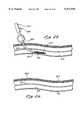
- FIG. 18is a view of the access device of the presently preferred embodiment inserted within a body passage showing the obturator assembly in the removal profile;
- FIG. 19is a view of the access device of the presently preferred embodiment inserted within a body passage showing the expandable containment member in the open condition with the obturator assembly removed and with a therapeutic balloon catheter inserted;
- FIG. 20is a view of the access device of the presently preferred embodiment inserted within a body passage illustrating the use of a balloon catheter through the access device to treat an occlusion;
- FIG. 21is a view of the access device of the presently preferred embodiment in use within a body passage as a balloon catheter withdraws an occlusive mass toward the expandable containment member of the access device;
- FIG. 22illustrates the containment of an occlusive mass within the expandable containment member according to the presently preferred embodiment
- FIG. 23is a view of the expanded containment member of the access device of the presently preferred embodiment with the balloon catheter removed;
- FIG. 24is a view of the access device of the presently preferred embodiment showing the obturator assembly being re-inserted to collapse the expandable containment member for removal from the body passage;
- FIG. 25is a view of the collapsed expandable containment member and obturator assembly of the presently preferred embodiment, prior to removal from a body passage;
- FIG. 26is a view of a body passage with the access device of the presently preferred embodiment removed;
- FIGS. 27A-Jare axial cross-section views of a fourth alternative embodiment of the present invention showing the sequence of deployment of an expandable containment member
- FIGS. 28A-Hare axial cross-section views of a fifth alternative embodiment of the present invention showing the sequence of deployment of an expandable containment member
- FIG. 29is a side-elevation view partially in section of a further embodiment of the invention.
- FIG. 30is an axial cross-section view of the distal tip of the embodiment of FIG. 29, illustrating a low-profile state
- FIG. 31is an axial cross-section view similar to FIG. 30 and showing an intermediate state of the distal tip
- FIG. 32is an axial cross-section view similar to FIG. 31 and showing the distal tip in an expanded state;
- FIGS. 33A-Cillustrate steps in operation of an actuator attached to an inner tube
- FIG. 33Aillustrates the actuator in a distal position
- FIG. 33Billustrates the actuator in a more proximal position
- FIG. 33Cillustrates movement of the actuator back to the distal position
- FIGS. 34A-Cillustrate steps in operation of an actuator attached to an outer tube
- FIG. 34Aillustrates the actuator in a proximal position
- FIG. 34Billustrates the actuator in a more distal position
- FIG. 34Cillustrates movement of the actuator back to the proximal position.
- an access device 30 of the present inventionis illustrated having a sheath assembly 32, as best seen in FIG. 2, and an obturator assembly 34, as best seen in FIG. 3, inserted through the sheath assembly 32.
- the sheath assembly 32comprises an outer flexible tube 36 having a proximal tube end 38 and a distal tube end 41.
- the sheath assembly 32further comprises an accessory device 45 and an expandable containment member 43, which is connected to the outer flexible tube 36 near the distal tube end 41.
- the obturator assembly 34comprises a proximal obturator end 47 and a distal obturator end 50.
- the obturator end area 52includes an obturator expandable cone 54 and a proximal portion 56.
- the expandable containment member 43 of the sheath assembly 32is connected to the proximal portion 56 of the obturator end area 52.
- An obturator handle 58 of the obturator assembly 34is connected to the accessory device 45 of the sheath assembly 32 via a handle connector 61.
- the outer flexible tube 36 of the sheath assembly 32comprises the expandable containment member 43 and a connector portion 63.
- the portion of the outer flexible tube 36 located between the expandable containment member 43 and the connector portion 63preferably comprises a semi-rigid portion of solid walled tubing, and the expandable containment member 43 preferably comprises a braided tubular component.
- the expandable containment member 43is preferably joined to this solid walled tubular member by either bonding or fusion. As presently embodied, the expandable containment member 43 is bonded to the solid walled tubular portion using thermal fusion.
- the connector portion 63preferably comprises a solid plastic component, which is connected to the solid walled tubular portion of the outer flexible tube 36.
- the connector portion 63removably connects the outer flexible tube 36 to the tube connector 67 of the accessory device 45.
- the connector portion 63comprises threads (not shown) which fit into the tube connector 67 for a snug fit.
- a lumenis formed within the outer flexible tube 36 between the distal tube end 41 and the proximal tube end 38. This lumen is preferably sized and configured to accommodate a shaft portion of the obturator assembly 34 (FIG. 3). The lumen of the outer flexible tube 36 may also removably accommodate other instruments.
- a side port 70 of the sheath assembly 32is adapted for applying/removing air or fluid to/from the lumen of the outer flexible tube 36, under either positive or negative pressure. Instruments, such as the obturator assembly 34 (FIG. 3) can be inserted through the handle connector 61 of the sheath assembly 32 and out of the expandable containment member 43, for example.
- Finger tabs 71 of the accessory device 45operate to open and seal access to the lumen of the outer flexible tube 36, depending on the configuration of the two finger tabs 71.
- the obturator assembly 34comprises an obturator shaft 72, which comprises the obturator end area 52 and which is connected to the obturator handle 58 via a connector portion 74.
- the obturator expandable cone 54can be radially expanded and contracted by movement of the slidable actuator 76.
- the distal obturator end 50 of the obturator assembly 34is inserted through the handle connector 61 of the sheath assembly 32. The distal obturator end is then moved through the lumen of the outer flexible tube 36, and out of the expandable containment member 43 of the sheath assembly 32.
- the connector portion 74 of the obturator assembly 34accommodates threads of the handle connector 61 therein.
- the obturator end area 52extends distally out of the expandable containment member 43 of the sheath assembly 32.
- FIG. 4is a cross-sectional view of the access device 30 of the present invention configured in an introductory profile, unexpanded condition.
- the lumen 78 of the outer flexible tube 36is shown having a guidewire 81 inserted therethrough.
- the guidewire 81operates as both a stiffener and a leader for the access device 30, during insertion of the access device 30 into a body passage, for example.
- the guidewire 81provides strength to the access device 30, and allows for manufacturing of the outer flexible tube 36 and the obturator shaft 72 components in lightweight and thin-walled constructions in order to conserve space within the body passage.
- the use of the guidewire 81also serves to reduce the strength requirements of the outer flexible tube 36 and the obturator shaft 72 components during insertion and deployment of the expandable members 43 and/or 54.
- the expandable containment member 43comprises a proximal member end 83 and a distal member end 85.
- the proximal member end 83 of the expandable containment member 43is preferably bonded to the solid walled portion of the flexible tube 36, and the distal member end 85 of the expandable containment member 43 is bonded, via a bonded portion 87, around the obturator shaft 72.
- the outer slidable obturator sleeve 90is preferably fused to the distal member end 85 of the expandable containment member 43 at the bonded portion 87.
- the outer slidable obturator sleeve 90is fused to the tubular mesh of the expandable containment member 43 by heating the outer flexible tube 36 and the expandable containment member 43 while holding them in compression and over an inserted mandrel. This construction results in no substantial buildup of material in the bonded portion 87 and a minimum increase of diameter in the bonded portion 87.
- the outer flexible tube 36 materialis forced to flow into the woven material of the expandable containment member 43 and into and around the individual woven elements thereof.
- the woven material of the expandable containment member 43is subsequently folded back to form a bending area 107 in the woven mesh of the expandable containment member 43, and extended proximally to overlap the distal tube end 41 of the outer flexible tube 36.
- the proximal member end 83 of the expandable containment member 43is fused to the outer flexible tube 36 in a similar manner.
- the obturator shaft 72comprises an outer slidable obturator sleeve 90, an intermediate slidable obturator sleeve 92, and an inner fixed obturator sleeve 94.
- the guidewire 81fits within the inner fixed obturator sleeve 94.
- the outer flexible tube 36 of the sheath assembly 32fits around the outer slidable obturator sleeve 90.
- a portion of the outer slidable obturator sleeve 90is recessed at the bonded portion 87 to thereby accommodate the distal member end 85 of the expandable containment member 43 within this recessed portion of the outer slidable obturator sleeve 90.
- the outer slidable obturator sleeve 90continues distally of the expandable containment member 43 as the obturator end area 52. More particularly, the outer slidable obturator sleeve 90 at the obturator end area 52 comprises a solid walled portion 97, the obturator expandable cone 54, and a distal solid walled portion 99.
- the obturator expandable cone 54preferably comprises a woven tubular structure, which may be similar to the braided material of the expandable containment member 43.
- the obturator expandable cone 54is preferably fused between the solid walled portion 97 and the distal solid walled portion 99 of the outer slidable obturator sleeve 90, at the proximal fuse location 101 and the distal fuse location 103, respectively.
- the bonded portion 87 of the outer slidable obturator sleeve 90holds the expandable containment member 43 in place during insertion of the access device 30 into a body passage.
- the obturator shaft 72may be moved distally, relative to the sheath assembly 32, to thereby release the bonded portion 87 from within the recess of the outer slidable obturator sleeve 90.
- a purpose of the outer slidable obturator sleeve 90, the intermediate slidable obturator sleeve 92, and the inner fixed obturator sleeve 94is to facilitate relative movement between the proximal fuse location 101 and the distal fuse location 103 of the outer slidable obturator sleeve 90, without requiring movement of the guidewire 81.
- the guidewire 81is slidably contained within the inner fixed obturator sleeve 94.
- a distal end of the intermediate slidable obturator sleeve 92is connected to the solid walled portion 97 of the outer slidable obturator sleeve 90, and a distal end of the inner fixed obturator sleeve 94 is connected to the distal solid walled portion 99. Since the distal end of the inner fixed obturator sleeve 94 is connected to the distal solid walled portion 99 and the distal end of the intermediate slidable obturator sleeve 92 is connected to the solid walled portion 97, movement of these two distal ends relative to one another results in movement of the two ends 101, 103 of the obturator expandable cone 54.
- intermediate slidable actuator sleeve 92may be moved toward the distal end of the inner fixed obturator sleeve 94, to thereby move the proximal fuse location 101 toward the distal fuse location 103.
- both the proximal portion 56 of the obturator end area 52 and the obturator expandable cone 54press proximally against the expandable containment member 43, to thereby move the distal member end 85 about a bending area 107 of the expandable containment member 43.
- the bending area 107approximately bisects the length of the expandable containment member 43, and allows further movement of the obturator expandable cone 54 in the proximal direction to configure the expandable containment member 43 into a cone shape.
- a distal portion of the expandable containment member 43comprises an inner surface 108 of the cone and the bending area 107 forms an enlarged distally facing rim of the cone.
- the inside surface 108 of the expandable containment member 43thus folds into the outside surface 110 about the bending area 107, to form a cone. This folding action occurs at a point near the expansion limit of the woven mesh of the expandable containment member 43.
- the cone thus formedcomprises a double-wall structure having an outer surface 110 and an inside surface 108 and a space therebetween forming a truss.
- the large distally facing rim 107 of the coneis adapted for intimate contact with intimal tissue within a body passage, for example.
- This bending area 107comprises folded elements of mesh of the expandable containment member 43 which greatly increase the hoop strength of the cone while, at the same time, presenting a relatively a traumatic distal feature without any exposed mesh element ends extending therefrom.
- the obturator shaft 72 of the obturator assembly 34is moved distally away from the cone, as illustrated in FIG. 6. Additionally, the distal end of the inner fixed obturator sleeve 94 is moved away from the distal end of the intermediate slidable obturator sleeve 92, to thereby collapse the obturator expandable cone 54. After the obturator expandable cone 54 has been collapsed, the obturator shaft 72 is again moved proximally. The obturator shaft 72 is moved proximally until the entire obturator assembly 34 is removed from the lumen 78 of the outer flexible tube 36. Additionally, the guidewire 81 is removed from the lumen 78.
- FIG. 7illustrates the outer flexible tube 36, with the expandable containment member 43 configured into the cone shape, having an enlarged distally facing rim 107.
- the lumen 78is free for subsequent introduction of other instruments, such as a therapeutic balloon catheter.
- FIG. 8illustrates the entire sheath assembly 32 with the obturator assembly 34 (FIG. 3) removed therefrom and the expandable containment member 43 shaped into a cone.
- FIGS. 9-12illustrate an alternative embodiment of the present invention where the obturator shaft 112 comprises a single tube, which accommodates a guidewire 114.
- the obturator shaft 112slidably fits within an outer flexible tube 116, which comprises an expandable containment member 118.
- a distal end 121 of the expandable containment member 118is fused or bonded to the connection area 123.
- the distal end 121 of the expandable containment member 118is moved toward the proximal end 125 of the expandable containment member 118.
- the expandable containment member 118expands and bows outwardly about the bending areas 127.
- the distal end 130 of the guidewire 114can remain stationary while the obturator shaft 112 and the outer flexible tube 116 are moved relative to one another.
- the distal end 121may be mechanically connected to the connection area 123, for example.
- FIG. 11corresponds to FIG. 6, where the inner surface 132 is folded inside of the outer surface 134 and a large distally facing rim 127 forms a cone.
- the obturator shaft 112 in this embodimentdoes not need to be moved distally before removal but, instead, may be moved proximally from the configuration of FIG. 11 out of the lumen 138 (FIG. 12) of the outer flexible tube 116.
- the obturator shaft 72does not need to be moved forward either, and the obturator expandable cone 54 does not need to be collapsed, before removal of the obturator shaft 72 from the lumen 78.
- FIGS. 4-7the embodiment of FIGS.
- FIGS. 4-7may benefit from the collapsing of the obturator expandable cone 54 before removal of the obturator shaft 72. It is noted that a preferred operation of the embodiment of FIGS. 4-7 involves moving the distal ends of the intermediate slidable obturator sleeve 92 and the inner fixed obturator sleeve 94 away from one another, to thereby apply tension to the obturator expandable cone 54 and reduce the profile or diameter of this obturator expandable cone 54, before removal of the obturator shaft 72.
- FIGS. 13A-13Gillustrate another embodiment of the present invention, where a guidewire 145 having a distal end 147 is inserted within an inner slidable obturator sleeve 152.
- the inner slidable obturator sleeve 152fits within an outer obturator containment sleeve 154
- the outer obturator containment sleeve 154fits within an outer flexible tube 156 of a sheath assembly.
- An expandable containment member 158is connected to the outer flexible tube 156, and is also connected to the holding ends 161 of the outer obturator containment sleeve 154.
- the inner slidable obturator sleeve 152comprises an obturator expandable cone 165.
- the two holding ends 161 of the outer obturator containment sleeve 154hold the distal ends 167 of the expandable containment member 158 in place.
- the obturator expandable cone 165is then expanded and moved proximally into contact with the distal end 167 of the expandable containment member 158.
- the expandable containment member 158bends about the bending portions 172 to thereby form a cone or funnel.
- the obturator expandable cone 165is then collapsed, as shown in FIG. 13C, and the distal ends 167 of the expandable containment member 158 are released from the holding ends 161 of the outer obturator containment sleeve 154.
- the expandable containment member 165, the outer obturator containment sleeve 154, the inner slidable obturator sleeve 152, and the guidewire 145are then removed from the outer flexible tube 156, as illustrated in FIG. 13D.
- the expandable containment member 158is collapsed back into a low profile configuration.
- the outer flexible tube 156may be removed from the body passage without collapsing the expandable containment member 158. As shown in FIGS.
- FIGS. 14A-14Dillustrate another embodiment of the present invention, where the obturator expandable cone of the previous embodiment is replaced with an enlarged diameter portion 178.
- An inner slidable obturator sleeve 181fits within an outer obturator containment sleeve 183, and the outer obturator containment sleeve 183 fits within an outer flexible tube 185.
- the outer flexible tube 185is connected to an expandable containment member 187, which comprises a distal end 190 that is held by holding ends 192 of the outer obturator containment sleeve 183.
- proximal movement of the holding ends 192compresses the expandable containment member 187, and moves the distal ends 190 about the bending portions 194 to thereby form a cone, as illustrated in FIG. 14B.
- the holding ends 192are further moved proximally to thereby release the distal ends 190 of the expandable containment member 187, as shown in FIG. 14C.
- the enlarged diameter portion 178is then moved proximally into close proximity to the holding ends 192.
- the inner slidable obturator sleeve 181, the outer obturator containment sleeve 183, and the enlarged diameter portion 178are all moved proximally out of the lumen 198 of the outer flexible tube 185.
- an access device 201is inserted over a placed guidewire 203 through a puncture site 205 in the skin 207 of a patient, and through a vessel puncture 212 of a body passage 214.
- the access device 201is urged over the guidewire 203 to a desired area proximal of an occlusive material 218 within the lumen 219 of the body passage 214.
- the profiles of the expandable containment member 221 and the obturator expandable cone 223are maintained at a minimum by maintaining tension on these members 221, 223 through the distal position of the slidable obturator 225 on the obturator handle 227.
- the slidable actuator 225is moved to a second, proximal position on the obturator handle 227 resulting in the expansion of the obturator expandable cone 223.
- the bond portion 87(as best seen in FIG. 4) is broken.
- the obturator expandable cone 223is then moved proximally against the distal end of the expandable containment member 221, resulting in expansion of the expandable containment member 221.
- FIG. 17illustrates how the obturator expandable cone 223 is used to urge the expandable containment member 221 into a cone shape.
- the fully expanded obturator expandable cone 223is pulled proximally against the distal end of the expandable containment member 221, until this distal end of the expandable containment member 221 begins to invert. Once the expandable containment member 221 has been formed into a cone shape, the fully expanded obturator expandable cone 223 is urged proximally into the cone shape and into the outer tube 231 of the access device.
- a therapeutic balloon catheter 232may be placed into the lumen of the tube 231, as shown in FIG. 19.
- the therapeutic balloon catheter 232is advanced distally past the occluding material 218 before the balloon 234 is expanded.
- Other instrumentsmay be inserted through the outer tube 231, as well.
- the therapeutic balloon catheter 232is expanded at a distal location, relative to the occluding material 218, and the occluding material 218 is then urged proximally toward and into the enlarged opening of the funnel formed by the expandable containment member 221.
- FIG. 21illustrates the compressing of the occluding material 218 into the expandable containment member 221 by the balloon 234 of the therapeutic balloon catheter 232.
- FIG. 22shows the occluding material 218 being completely captured within the expandable containment member 221
- FIG. 23illustrates the expandable containment member 221 and the outer tube 231 after the balloon 234 has been reduced in diameter and removed.
- the balloon 234is drawn proximally through the outer tube 231, with the continued application of suction, to thereby transport the occluding material 218 out of the outer tube 231.
- the obturator assemblyis reinserted into the outer tube 231, as illustrated in FIGS. 24 and 25.
- the obturator expandable cone 223is expanded to engage the inverted end of the expandable containment member 221.
- the funnel formed by the expandable containment member 221is reverted to a low profile configuration.
- the obturator expandable cone 223is also reduced to a low profile configuration, as shown in FIG. 25, and the access device 201 is removed.
- FIG. 26illustrates the body passage 214 and the skin 207 after removal of the access device 201 therefrom. An occlusion free lumen 219 with minimal punctures 205, 212 remains.
- FIGS. 27A-Jillustrate a fourth alternative embodiment of the present invention.
- a guide wire 301fits within an inner-fixed obturator sleeve 303 and an outer slidable obturator sleeve 305.
- a reversible sheath 307comprises a proximal sheath end 309 and a distal sheath end 311. As presently embodied, the reversible sheath 307 is secured to the distal end 315 of the guidewire 301.
- the outer slidable obturator sleeve 305comprises an obturator expandable cone 317, which is connected to a distal portion of the outer slidable obturator sleeve 305.
- An outer flexible tube 321fits around the outer slidable obturator sleeve 305 and the obturator expandable cone 317.
- the outer flexible tube 321comprises a distal tube end 330, which is connected to an expandable containment member 333.
- the expandable containment member 333fits beneath the reversible sheath 307 during insertion of the device into a body passage, for example.
- the reversible sheath 307comprises a braided material similar to the material comprising the expandable containment member 333.
- the reversible sheath 307covers the expandable containment member 333 so that forces acting to expand the expandable containment member 333 upon insertion into a vessel are applied to the reversible sheath 307 in a direction that compresses the material of the reversible sheath 307 rather than expand the material.
- the reversible sheath 307is moved distally so that the proximal sheath end 309 of the reversible sheath 307 is beyond the distal end 350 of the expandable containment member 333, as illustrated in FIG. 27B.
- the reversible sheath 307is then further moved distally to allow for deployment of the obturator expandable cone 317, as illustrated in FIG. 27C.
- the obturator expandable cone 317is moved distally through a lumen formed by the expandable containment member 333, until the obturator expandable cone 317 is able to expand, as illustrated in FIG. 27D.
- the obturator expandable cone 317is subsequently moved proximally against the distal end 350 of the expandable containment member 333. Movement of the obturator expandable cone 317 against the distal end 350 of the expandable containment member 333 results in an expansion of the expandable containment member 333, as illustrated in FIG. 27E. After the obturator expandable cone 317 is moved into the expandable containment member 333 (FIG. 27E), the obturator expandable cone 317 is collapsed into a low-diameter configuration, as illustrated in FIG. 27F.
- the obturator expandable cone 317is moved proximally into the expandable containment member 333 and into the outer flexible tube 321, as illustrated in FIG. 27G.
- the reversible sheath 307is moved proximally against the expandable containment member 333, as illustrated in FIG. 27G.
- the reversible sheath 307is further moved proximally against the expandable containment member 333 (FIG. 27H), until the proximal sheath end 309 is moved past the distal sheath end 311, as illustrated in FIG. 27I.
- Movement of the proximal sheath end 309 past the distal sheath end 311allows the reversible sheath 307 to invert and fold back onto itself as the distal end 315 is withdrawn from within the outer flexible tube 321, as illustrated in FIG. 27J.
- FIGS. 28A-28Hillustrate a fifth alternative embodiment of the present invention, where the obturator expandable cone 317 of the fourth alternative embodiment is not used.
- the expandable containment member 333is urged to a fully expanded configuration as the reversible sheath 307 is inverted and folded back onto itself during withdrawal of the distal end 315 from the outer flexible tube 321.
- FIG. 29illustrates a further embodiment of the invention wherein the access device is designated by the reference numeral 401.
- the device 401has an axis 402 extending between a distal end 403 and a proximal end 405.
- An expandable containment member 407is disposed at the distal end 403 and transformable between a low-profile state and a high-profile state.
- this member 407is formed of a mesh 408 with the configuration of a cylinder having a proximal end 409 and a distal end 412.
- the mesh 408 associated with the containment member 407is coated with an elastic dispersion 413 that closes the interstices between the woven elements forming the mesh.
- This dispersion 413may include, for example, an air-curable silicone which is sufficiently elastic that it does not interfere with operation of the containment member 407.
- a handle 414 having a distal wall 415can be provided along with a thumb tab or actuator 416 which is slideable on the handle 414.
- the actuator 416which in this embodiment has a distally-facing surface 417 and a proximally-facing surface 419, is operable through an outer tube 418 having a distal end 421, and an inner tube 423 having a proximal end 424 and a distal end 425.
- the inner tube 423has an axial lumen which functions as a working channel 427 for the device 401.
- the proximal end 409 of the cylindrical containment member 407is attached to the distal end 421 of the outer tube 418.
- the distal end 412 of the containment member 407can be attached to the distal end 425 of the inner tube 423.
- the handle 414can be attached to one of the outer tube 418 or inner tube 423.
- the actuator 416can be attached to the other of the outer tube 418 and inner tube 423. This relationship permits operation of the actuator 416 relative to the handle 414 in order to transform the containment member 407 between its low-profile and high-profile states.
- the distal end 403 of the access device 401is illustrated in greater detail in the enlarged view of FIG. 30.
- the proximal end 409 of the containment member 407can be joined to the distal end 421 of the outer tube 418 by a coupling section 432.
- This joining of the containment member 407 and outer tube 418can be accomplished by adhesion or fusion in the coupling section 432.
- the wall thickness of the coupling section 432 and the containment member 407be not greater than the wall thickness of the outer tube 418.
- the distal end 412 of the containment member 407can be attached to the distal end 425 of the inner tube 423 at a coupling section 434.
- this transformationoccurs as the inner tube 423 moves proximally relative to the outer tube 418.
- this proximal movement of the inner tube 423 relative to the outer tube 418places the containment member 407 in a state of axial compression.
- the containment member 407is formed of a braided mesh, the mechanical properties of the containment member will not support a compressive load. Rather, the containment member 407 tends to respond to the axial compression by expanding radially outwardly while shortening its length.
- the containment member 407begins to invert, as illustrated in FIG. 31.
- the containment member 407achieves a high-profile state, as illustrated in FIG. 32.
- the containment memberforms a funnel 436 having an inner wall 438 and an outer wall 441 joined at their distal ends by a line of intersection 443.
- This line of intersection 443has a circular configuration in the illustrated embodiment and defines the distal end 403 of the access device 401 in the high-profile state.
- this circular line of intersection 443it is desirable that this circular line of intersection 443 have a diameter greater than the outer tube 418.
- both the inner wall 438 and outer wall 441 of the funnel 436have an angle with respect to the axis 402 of the access device 401.
- this angle relative to the axis 402is greater with respect to the inner wall 438 than with respect to the outer wall 441.
- these angles of the walls 438 and 431, as well as the diameter of the circular line of intersection 443,can be controlled at the proximal end 405 (FIG. 29) by adjusting the relative position of the outer and inner tubes 418 and 423, respectively.
- This adjustment of the outer tube 418 relative to the inner tube 423can be better understood with reference to FIGS. 33A-33C, which show different positions of the actuator 416 relative to the handle 14, and the accompanying transformation of the containment member 407 at the distal end 403.
- the actuator 416is fixed to the inner tube 423 while the handle 414 is fixed to the outer tube 418.
- the actuator 416is movable between a distal position and a proximal position, respectively.
- the inner tube 421extends a maximum distance distally of the outer tube 418. This causes the containment member 407 to achieve the low-profile state.
- the actuator 416When the actuator 416 is moved to its proximal position, as illustrated in FIG. 33B, the ends of the tubes 418 and 423 are minimally separated to achieve the high-profile state and to form the funnel 436. Between these low-profile and high-profile states, the containment member 407 is generally axially compressed resulting in radial expansion and formation of the funnel 436. Thus, between the two extremes illustrated in FIGS. 33A and 34B, the actuator has an infinite number of positions, each of which is associated with a known configuration of the containment member 407 at the distal end 403.
- the actuator 416can be operated by holding handle 414 stationary and pressing the thumb against the distally-facing surface 417, as shown by arrow 428. Moving the actuator 416 proximally, one can achieve the high-profile state as illustrated in FIG. 33B. Conversely, by holding the handle 414 stationary and pressing the thumb against the proximal-facing surface 419, as shown by arrow 429, the containment member 407 can be returned to the low-profile state as illustrated in FIG. 33C.
- indicia 430can be provided on the handle 414 to provide the user with an indication at the proximal end 405 as to the profile of the containment member 407 at the distal end 403.
- This indiciamight even include pictures illustrating the configuration of the distal tip 403.
- FIG. 33In the embodiment of FIG. 33, wherein the actuator 416 is fixed to the inner tube 423, movement of the actuator 416 relative to the handle 414 also varies the length of a protruding section 424 of the inner tube 423. This variation in length can be seen in FIGS. 33A and 33B. A further embodiment of the invention illustrated in FIGS. 34A-34C does not have this variation in length of the protruding section 424.
- the actuator 416is fixed to the outer tube 418 while the handle 414 is fixed to the inner tube 421. Movement of the actuator 416 between its proximal and distal positions also transforms the profile of the containment member 407, but in a manner reversed from that previously discussed. Thus, as shown in FIG.
- the actuator 416 in its proximal positionis associated with the low-profile state of the containment member 407. Conversely, when the actuator 416 is moved to its distal position, as shown in FIG. 34B, the containment member 407 is transferred to its high-profile state.
- known variations in the shape of the containment member 407are associated with the various positions of the actuator 416 relative to the handle 414.
- an obturator 452 having a rounded nose 454, as illustrated in FIG. 34A,can be inserted into the working channel 427 and positioned so that the nose 454 extends slightly distally of the distal end 403 of the axis device 401.
- This obturator 452can also function to close the working channel 427, reduce the cross-sectional area of the working channel 427, provide an a traumatic tip, or even function as a dilator.
- many of these functionscan be achieved by other types of structure.
- the working channel 427could be reduced or occluded by a valve or cap 455 attached to the protruding proximal section 424 of the inner tube 423.
- this access device 401can be operated with a single hand and the mere movement of the user's thumb to control the position of the actuator 416 relative to the handle 414.
- a separate obturatorbe used to place the containment member 407 either in its high-profile state, or return it to its low-profile state. This transformation occurs by simply sliding the actuator 416 relative to the handle 414.
- these embodimentsrequire fewer steps in their operation, and that operation is considerably more intuitive.
- the structurescan be achieved with fewer components and an assembly process that is greatly simplified.
Landscapes
- Health & Medical Sciences (AREA)
- Surgery (AREA)
- Life Sciences & Earth Sciences (AREA)
- Heart & Thoracic Surgery (AREA)
- Nuclear Medicine, Radiotherapy & Molecular Imaging (AREA)
- Vascular Medicine (AREA)
- Engineering & Computer Science (AREA)
- Biomedical Technology (AREA)
- Orthopedic Medicine & Surgery (AREA)
- Medical Informatics (AREA)
- Molecular Biology (AREA)
- Animal Behavior & Ethology (AREA)
- General Health & Medical Sciences (AREA)
- Public Health (AREA)
- Veterinary Medicine (AREA)
- Surgical Instruments (AREA)
Abstract
Description
Claims (16)
Priority Applications (1)
| Application Number | Priority Date | Filing Date | Title |
|---|---|---|---|
| US08/974,300US5971938A (en) | 1996-04-02 | 1997-11-19 | Access device with expandable containment member |
Applications Claiming Priority (3)
| Application Number | Priority Date | Filing Date | Title |
|---|---|---|---|
| US1450696P | 1996-04-02 | 1996-04-02 | |
| US08/686,175US5846251A (en) | 1996-07-22 | 1996-07-22 | Access device with expandable containment member |
| US08/974,300US5971938A (en) | 1996-04-02 | 1997-11-19 | Access device with expandable containment member |
Related Parent Applications (1)
| Application Number | Title | Priority Date | Filing Date |
|---|---|---|---|
| US08/686,175Continuation-In-PartUS5846251A (en) | 1996-04-02 | 1996-07-22 | Access device with expandable containment member |
Publications (1)
| Publication Number | Publication Date |
|---|---|
| US5971938Atrue US5971938A (en) | 1999-10-26 |
Family
ID=26686185
Family Applications (1)
| Application Number | Title | Priority Date | Filing Date |
|---|---|---|---|
| US08/974,300Expired - LifetimeUS5971938A (en) | 1996-04-02 | 1997-11-19 | Access device with expandable containment member |
Country Status (1)
| Country | Link |
|---|---|
| US (1) | US5971938A (en) |
Cited By (114)
| Publication number | Priority date | Publication date | Assignee | Title |
|---|---|---|---|---|
| US6387095B1 (en) | 1998-02-09 | 2002-05-14 | Loren R. Kennett | Surgical device comprising a radially expandable non-conductive sheath |
| US20030195537A1 (en)* | 1998-02-10 | 2003-10-16 | Artemis Medical, Inc. | Medical device and methods for use |
| US20040019322A1 (en)* | 2002-07-23 | 2004-01-29 | Hoffmann Gerard Von | Intracranial aspiration catheter |
| US20040097881A1 (en)* | 2002-11-15 | 2004-05-20 | Applied Medical Resources Corporation | Kink-resistant access sheath and method of making same |
| US20040133213A1 (en)* | 2001-12-12 | 2004-07-08 | Demetrius Bagley | Articulating stone basket |
| US20050049619A1 (en)* | 2000-06-29 | 2005-03-03 | Concentric Medical, Inc. | Systems, methods and devices for removing obstructions from a blood vessel |
| US20050187570A1 (en)* | 2004-02-19 | 2005-08-25 | Applied Medical Resources Corporation | Embolectomy capture sheath |
| US20050209627A1 (en)* | 2004-03-18 | 2005-09-22 | Kick George F | Expandable medical access device |
| US20050222576A1 (en)* | 2004-03-18 | 2005-10-06 | Kick George F | Expandable medical access device |
| US20050222604A1 (en)* | 2004-03-31 | 2005-10-06 | Cook Incorporated | Self centering delivery catheter |
| WO2007048259A1 (en)* | 2005-10-28 | 2007-05-03 | Carag Ag | Intravascular device |
| US7220269B1 (en)* | 2003-11-06 | 2007-05-22 | Possis Medical, Inc. | Thrombectomy catheter system with occluder and method of using same |
| US7374560B2 (en) | 2001-05-01 | 2008-05-20 | St. Jude Medical, Cardiology Division, Inc. | Emboli protection devices and related methods of use |
| US7422579B2 (en) | 2001-05-01 | 2008-09-09 | St. Jude Medical Cardiology Divison, Inc. | Emboli protection devices and related methods of use |
| US20080312681A1 (en)* | 2006-10-16 | 2008-12-18 | Possis Medical, Inc. | Catheter for removal of an organized embolic thrombus |
| US20090157043A1 (en)* | 2007-12-14 | 2009-06-18 | Abbott Cardiovascular Systems Inc. | Low profile agent delivery perfusion catheter having a funnel shaped membrane |
| US7604612B2 (en) | 2001-05-01 | 2009-10-20 | St. Jude Medical, Cardiology Division, Inc. | Emboli protection devices and related methods of use |
| US20100036409A1 (en)* | 2002-02-28 | 2010-02-11 | Scheib Mark S | Retractable dilator needle |
| US20100114017A1 (en)* | 2002-07-23 | 2010-05-06 | Reverse Medical Corporation | Systems and methods for removing obstructive matter from body lumens and treating vascular defects |
| US20100211009A1 (en)* | 2007-12-14 | 2010-08-19 | Abbott Cardiovascular Systems Inc. | Perfusion catheter having array of funnel shaped membranes |
| US7892203B2 (en) | 2004-09-09 | 2011-02-22 | Onset Medical Corporation | Expandable transluminal sheath |
| US8092481B2 (en) | 2005-06-03 | 2012-01-10 | Onset Medical Corporation | Expandable percutaneous sheath |
| US8221348B2 (en) | 2005-07-07 | 2012-07-17 | St. Jude Medical, Cardiology Division, Inc. | Embolic protection device and methods of use |
| US8480696B2 (en)* | 2004-06-16 | 2013-07-09 | Medtronic, Inc. | Minimally invasive coring vein harvester |
| US8512352B2 (en) | 2007-04-17 | 2013-08-20 | Lazarus Effect, Inc. | Complex wire formed devices |
| US8545526B2 (en) | 2007-12-26 | 2013-10-01 | Lazarus Effect, Inc. | Retrieval systems and methods for use thereof |
| US8597277B2 (en) | 2004-09-09 | 2013-12-03 | Onset Medical Corporation | Expandable transluminal sheath |
| WO2014022145A1 (en)* | 2012-08-02 | 2014-02-06 | Rbkpark Llc | Medical devices including blood clot removing medical devices, and methods of using same |
| US8795322B2 (en) | 2002-04-01 | 2014-08-05 | W. L. Gore & Associates, Inc. | Methods of manufacture and use of endoluminal devices |
| US8795305B2 (en) | 2011-05-23 | 2014-08-05 | Lazarus Effect, Inc. | Retrieval systems and methods for use thereof |
| US8801736B2 (en) | 2010-11-19 | 2014-08-12 | Gil Vardi | Percutaneous thrombus extraction device and method |
| US8801748B2 (en) | 2010-01-22 | 2014-08-12 | Lazarus Effect, Inc. | Retrieval systems and methods for use thereof |
| US9023077B2 (en) | 2002-10-17 | 2015-05-05 | W.L. Gore & Associates, Inc. | Embolic filter frame having looped support strut elements |
| US9204887B2 (en) | 2012-08-14 | 2015-12-08 | W. L. Gore & Associates, Inc. | Devices and systems for thrombus treatment |
| US9241735B2 (en) | 2003-12-05 | 2016-01-26 | Onset Medical Corporation | Expandable percutaneous sheath |
| US20160022289A1 (en)* | 2014-07-28 | 2016-01-28 | Shaw P. Wan | Suction evacuation device |
| US9254371B2 (en) | 2009-03-06 | 2016-02-09 | Lazarus Effect, Inc. | Retrieval systems and methods for use thereof |
| US9345499B2 (en) | 2011-05-26 | 2016-05-24 | Covidien Lp | Pressure activated foreign body removal system and method of use |
| US9597171B2 (en) | 2012-09-11 | 2017-03-21 | Covidien Lp | Retrieval catheter with expandable tip |
| US20170252051A1 (en)* | 2016-03-04 | 2017-09-07 | Well Lead Medical | Suction evacuation sheath |
| CN107205751A (en)* | 2015-01-13 | 2017-09-26 | 阿纳康达生物医药责任有限公司 | Thrombectomy device and system for removing vascular thrombus from blood vessel |
| US9827404B2 (en) | 2006-12-20 | 2017-11-28 | Onset Medical Corporation | Expandable trans-septal sheath |
| US9827084B2 (en) | 2007-10-26 | 2017-11-28 | Embolitech, Llc | Intravascular guidewire filter system for pulmonary embolism protection and embolism removal or maceration |
| US9924958B2 (en) | 2010-07-15 | 2018-03-27 | Covidien Lp | Retrieval systems and methods for use thereof |
| US9931128B2 (en) | 2006-02-03 | 2018-04-03 | Covidien Lp | Methods for restoring blood flow within blocked vasculature |
| US20180206866A1 (en)* | 2014-07-28 | 2018-07-26 | Shaw P. Wan | Suction evacuation device |
| US20180235743A1 (en)* | 2017-02-23 | 2018-08-23 | Boston Scientific Scimed, Inc. | Medical drain device |
| JP2018134534A (en)* | 2013-12-03 | 2018-08-30 | 川澄化学工業株式会社 | Intravascular foreign body removal catheter |
| US10064635B2 (en) | 2007-04-17 | 2018-09-04 | Covidien Lp | Articulating retrieval devices |
| US10076346B2 (en) | 2007-04-17 | 2018-09-18 | Covidien Lp | Complex wire formed devices |
| US10130387B2 (en) | 2010-03-01 | 2018-11-20 | Covidien Lp | Introducer sheaths, thrombus collection devices, and associated methods |
| CN109620350A (en)* | 2018-12-31 | 2019-04-16 | 邓萍 | A kind of medical thrombus dredging structure |
| US10272231B2 (en) | 2004-09-09 | 2019-04-30 | Onset Medical Corporation | Expandable trans-septal sheath |
| US10383644B2 (en) | 2013-10-17 | 2019-08-20 | Covidien Lp | Mechanical thrombectomy with proximal occlusion |
| US10456560B2 (en) | 2015-02-11 | 2019-10-29 | Covidien Lp | Expandable tip medical devices and methods |
| US10478322B2 (en) | 2017-06-19 | 2019-11-19 | Covidien Lp | Retractor device for transforming a retrieval device from a deployed position to a delivery position |
| US10512478B2 (en) | 2016-04-25 | 2019-12-24 | Stryker Corporation | Clot-engulfing mechanical thrombectomy apparatuses |
| US10517624B2 (en) | 2016-06-03 | 2019-12-31 | Stryker Corporation | Inverting thrombectomy apparatuses and methods |
| US10575864B2 (en) | 2017-06-22 | 2020-03-03 | Covidien Lp | Securing element for resheathing an intravascular device and associated systems and methods |
| WO2020055908A1 (en)* | 2018-09-10 | 2020-03-19 | Stryker Corporation | Inverting thrombectomy apparatuses and methods of use |
| US10610245B2 (en) | 2016-09-12 | 2020-04-07 | Stryker Corporation | Self-rolling thrombectomy apparatuses and methods |
| EP3648686A1 (en)* | 2017-07-06 | 2020-05-13 | Stryker Corporation | Inverting thrombectomy apparatuses and methods |
| US10709464B2 (en) | 2017-05-12 | 2020-07-14 | Covidien Lp | Retrieval of material from vessel lumens |
| US10722257B2 (en) | 2017-05-12 | 2020-07-28 | Covidien Lp | Retrieval of material from vessel lumens |
| US10779843B2 (en) | 2017-11-09 | 2020-09-22 | Stryker Corporation | Inverting thrombectomy apparatuses having enhanced tracking |
| US10842513B2 (en) | 2016-04-25 | 2020-11-24 | Stryker Corporation | Methods for advancing inverting mechanical thrombectomy apparatuses in the vasculature |
| US10888342B2 (en) | 2016-04-25 | 2021-01-12 | Stryker Corporation | Anti-jamming and macerating thrombectomy apparatuses and methods |
| US20210015509A1 (en)* | 2017-01-12 | 2021-01-21 | Shaw P. Wan | Suction evacuation device |
| US20210022759A1 (en)* | 2017-01-12 | 2021-01-28 | Shaw P. Wan | Suction evacuation device |
| CN112472208A (en)* | 2019-09-11 | 2021-03-12 | 尼尔拉维有限公司 | Expandable opening catheter |
| CN112472211A (en)* | 2020-12-15 | 2021-03-12 | 上海融脉医疗科技有限公司 | Catheter device with expandable guide head end |
| US10945746B2 (en) | 2017-06-12 | 2021-03-16 | Covidien Lp | Tools for sheathing treatment devices and associated systems and methods |
| US20210113321A1 (en)* | 2014-12-12 | 2021-04-22 | Avantec Vascular Corporation | Ivc filter retrieval systems with interposed support members |
| US11026709B2 (en) | 2015-09-28 | 2021-06-08 | Stryker Corporation | Mechanical thrombectomy apparatuses and methods |
| US11076876B2 (en) | 2014-06-30 | 2021-08-03 | Neuravi Limited | System for removing a clot from a blood vessel |
| US11103265B2 (en) | 2018-05-14 | 2021-08-31 | Stryker Corporation | Inverting thrombectomy apparatuses and methods of use |
| US11103263B2 (en) | 2015-07-24 | 2021-08-31 | Ichor Vascular Inc. | Embolectomy system and methods of making and using same |
| US11129630B2 (en) | 2017-05-12 | 2021-09-28 | Covidien Lp | Retrieval of material from vessel lumens |
| US11191555B2 (en) | 2017-05-12 | 2021-12-07 | Covidien Lp | Retrieval of material from vessel lumens |
| US11202646B2 (en) | 2007-04-17 | 2021-12-21 | Covidien Lp | Articulating retrieval devices |
| US11253291B2 (en) | 2018-09-10 | 2022-02-22 | Stryker Corporation | Laser slotted grabbing device |
| US11298145B2 (en) | 2017-05-12 | 2022-04-12 | Covidien Lp | Retrieval of material from vessel lumens |
| US11311304B2 (en) | 2019-03-04 | 2022-04-26 | Neuravi Limited | Actuated clot retrieval catheter |
| US11382643B2 (en) | 2017-10-16 | 2022-07-12 | Retriever Medical, Inc. | Clot removal methods and devices with multiple independently controllable elements |
| US11395667B2 (en) | 2016-08-17 | 2022-07-26 | Neuravi Limited | Clot retrieval system for removing occlusive clot from a blood vessel |
| US11446045B2 (en) | 2014-06-13 | 2022-09-20 | Neuravi Limited | Devices and methods for removal of acute blockages from blood vessels |
| US11484328B2 (en) | 2014-03-11 | 2022-11-01 | Neuravi Limited | Clot retrieval system for removing occlusive clot from a blood vessel |
| US11497512B2 (en) | 2016-04-25 | 2022-11-15 | Stryker Corporation | Inverting thrombectomy apparatuses and methods |
| US11529158B2 (en) | 2004-03-25 | 2022-12-20 | Inari Medical, Inc. | Method for treating vascular occlusion |
| US11534191B2 (en) | 2019-01-11 | 2022-12-27 | Anaconda Biomed, S.L. | Loading device for loading a medical device into a catheter |
| EP4066877A3 (en)* | 2021-03-12 | 2022-12-28 | Cook Medical Technologies LLC | Endovascular delivery systems with radial orientation mechanisms |
| US11554005B2 (en) | 2018-08-13 | 2023-01-17 | Inari Medical, Inc. | System for treating embolism and associated devices and methods |
| US11589881B2 (en) | 2017-10-16 | 2023-02-28 | Retriever Medical, Inc. | Clot removal methods and devices with multiple independently controllable elements |
| US11633198B2 (en) | 2020-03-05 | 2023-04-25 | Neuravi Limited | Catheter proximal joint |
| US11633202B1 (en) | 2017-10-16 | 2023-04-25 | Retriever Medical, Inc. | Catheter based retrieval device with proximal body having axial freedom of movement |
| US11648028B2 (en) | 2012-11-20 | 2023-05-16 | Inari Medical, Inc. | Methods and apparatus for treating embolism |
| US11697011B2 (en) | 2017-09-06 | 2023-07-11 | Inari Medical, Inc. | Hemostasis valves and methods of use |
| US11759217B2 (en) | 2020-04-07 | 2023-09-19 | Neuravi Limited | Catheter tubular support |
| US11771446B2 (en) | 2020-10-19 | 2023-10-03 | Anaconda Biomed, S.L. | Thrombectomy system and method of use |
| US11779364B2 (en) | 2019-11-27 | 2023-10-10 | Neuravi Limited | Actuated expandable mouth thrombectomy catheter |
| EP4233744A3 (en)* | 2015-10-23 | 2023-11-01 | Inari Medical, Inc. | Device for intravascular treatment of vascular occlusion |
| US11806033B2 (en) | 2017-01-10 | 2023-11-07 | Inari Medical, Inc. | Devices and methods for treating vascular occlusion |
| US11839725B2 (en) | 2019-11-27 | 2023-12-12 | Neuravi Limited | Clot retrieval device with outer sheath and inner catheter |
| US11849963B2 (en) | 2018-01-26 | 2023-12-26 | Inari Medical, Inc. | Single insertion delivery system for treating embolism and associated systems and methods |
| US11864779B2 (en) | 2019-10-16 | 2024-01-09 | Inari Medical, Inc. | Systems, devices, and methods for treating vascular occlusions |
| US11872354B2 (en) | 2021-02-24 | 2024-01-16 | Neuravi Limited | Flexible catheter shaft frame with seam |
| US11883043B2 (en) | 2020-03-31 | 2024-01-30 | DePuy Synthes Products, Inc. | Catheter funnel extension |
| US11896247B2 (en) | 2016-04-25 | 2024-02-13 | Stryker Corporation | Inverting mechanical thrombectomy apparatuses |
| US11937839B2 (en) | 2021-09-28 | 2024-03-26 | Neuravi Limited | Catheter with electrically actuated expandable mouth |
| US11937838B2 (en) | 2013-10-21 | 2024-03-26 | Inari Medical, Inc. | Methods and apparatus for treating embolism |
| US11944327B2 (en) | 2020-03-05 | 2024-04-02 | Neuravi Limited | Expandable mouth aspirating clot retrieval catheter |
| US11986195B2 (en) | 2018-10-16 | 2024-05-21 | Anaconda Biomed, S.L. | Device and a thrombectomy apparatus for extraction of thrombus from a blood vessel |
| US12011186B2 (en) | 2021-10-28 | 2024-06-18 | Neuravi Limited | Bevel tip expandable mouth catheter with reinforcing ring |
| US12364496B2 (en) | 2022-01-11 | 2025-07-22 | Inari Medical, Inc. | Devices for removing clot material from intravascularly implanted devices, and associated systems and methods |
Citations (17)
| Publication number | Priority date | Publication date | Assignee | Title |
|---|---|---|---|---|
| US4243040A (en)* | 1979-09-17 | 1981-01-06 | Beecher William H | Extracting device for removing objects from human body passages |
| US4271839A (en)* | 1979-07-25 | 1981-06-09 | Thomas J. Fogarty | Dilation catheter method and apparatus |
| US4324262A (en)* | 1979-01-02 | 1982-04-13 | University Of Virginia Alumni Patents Foundation | Aspirating culture catheter and method of use |
| US4437859A (en)* | 1981-08-03 | 1984-03-20 | Drs Infusion Systems, Inc. | Hydraulic syringe drive |
| US4530698A (en)* | 1979-03-19 | 1985-07-23 | The United States Of America As Represented By The Department Of Health And Human Services | Method and apparatus for traversing blood vessels |
| US4921478A (en)* | 1988-02-23 | 1990-05-01 | C. R. Bard, Inc. | Cerebral balloon angioplasty system |
| US4997435A (en)* | 1989-09-25 | 1991-03-05 | Methodist Hospital Of Indiana Inc. | Percutaneous catheter with encapsulating receptacle |
| US5011488A (en)* | 1988-12-07 | 1991-04-30 | Robert Ginsburg | Thrombus extraction system |
| US5092839A (en)* | 1989-09-29 | 1992-03-03 | Kipperman Robert M | Coronary thrombectomy |
| US5190561A (en)* | 1991-01-23 | 1993-03-02 | Surgical Innovations, Inc. | Tissue and organ extractor |
| US5197961A (en)* | 1992-05-12 | 1993-03-30 | Castle Tris S | Toenail extender |
| US5222970A (en)* | 1991-09-06 | 1993-06-29 | William A. Cook Australia Pty. Ltd. | Method of and system for mounting a vascular occlusion balloon on a delivery catheter |
| US5234425A (en)* | 1989-03-03 | 1993-08-10 | Thomas J. Fogarty | Variable diameter sheath method and apparatus for use in body passages |
| US5250038A (en)* | 1992-10-09 | 1993-10-05 | Cook Incorporated | Multiple lumen vascular access introducer sheath |
| US5256146A (en)* | 1991-10-11 | 1993-10-26 | W. D. Ensminger | Vascular catheterization system with catheter anchoring feature |
| US5281205A (en)* | 1992-03-11 | 1994-01-25 | Mcpherson William E | Vascular access system and clearing method |
| US5295969A (en)* | 1992-04-27 | 1994-03-22 | Cathco, Inc. | Vascular access device with air-tight blood containment capability |
- 1997
- 1997-11-19USUS08/974,300patent/US5971938A/ennot_activeExpired - Lifetime
Patent Citations (17)
| Publication number | Priority date | Publication date | Assignee | Title |
|---|---|---|---|---|
| US4324262A (en)* | 1979-01-02 | 1982-04-13 | University Of Virginia Alumni Patents Foundation | Aspirating culture catheter and method of use |
| US4530698A (en)* | 1979-03-19 | 1985-07-23 | The United States Of America As Represented By The Department Of Health And Human Services | Method and apparatus for traversing blood vessels |
| US4271839A (en)* | 1979-07-25 | 1981-06-09 | Thomas J. Fogarty | Dilation catheter method and apparatus |
| US4243040A (en)* | 1979-09-17 | 1981-01-06 | Beecher William H | Extracting device for removing objects from human body passages |
| US4437859A (en)* | 1981-08-03 | 1984-03-20 | Drs Infusion Systems, Inc. | Hydraulic syringe drive |
| US4921478A (en)* | 1988-02-23 | 1990-05-01 | C. R. Bard, Inc. | Cerebral balloon angioplasty system |
| US5011488A (en)* | 1988-12-07 | 1991-04-30 | Robert Ginsburg | Thrombus extraction system |
| US5234425A (en)* | 1989-03-03 | 1993-08-10 | Thomas J. Fogarty | Variable diameter sheath method and apparatus for use in body passages |
| US4997435A (en)* | 1989-09-25 | 1991-03-05 | Methodist Hospital Of Indiana Inc. | Percutaneous catheter with encapsulating receptacle |
| US5092839A (en)* | 1989-09-29 | 1992-03-03 | Kipperman Robert M | Coronary thrombectomy |
| US5190561A (en)* | 1991-01-23 | 1993-03-02 | Surgical Innovations, Inc. | Tissue and organ extractor |
| US5222970A (en)* | 1991-09-06 | 1993-06-29 | William A. Cook Australia Pty. Ltd. | Method of and system for mounting a vascular occlusion balloon on a delivery catheter |
| US5256146A (en)* | 1991-10-11 | 1993-10-26 | W. D. Ensminger | Vascular catheterization system with catheter anchoring feature |
| US5281205A (en)* | 1992-03-11 | 1994-01-25 | Mcpherson William E | Vascular access system and clearing method |
| US5295969A (en)* | 1992-04-27 | 1994-03-22 | Cathco, Inc. | Vascular access device with air-tight blood containment capability |
| US5197961A (en)* | 1992-05-12 | 1993-03-30 | Castle Tris S | Toenail extender |
| US5250038A (en)* | 1992-10-09 | 1993-10-05 | Cook Incorporated | Multiple lumen vascular access introducer sheath |
Cited By (269)
| Publication number | Priority date | Publication date | Assignee | Title |
|---|---|---|---|---|
| US6387095B1 (en) | 1998-02-09 | 2002-05-14 | Loren R. Kennett | Surgical device comprising a radially expandable non-conductive sheath |
| US20030195537A1 (en)* | 1998-02-10 | 2003-10-16 | Artemis Medical, Inc. | Medical device and methods for use |
| US7491210B2 (en)* | 1998-02-10 | 2009-02-17 | Artemis Medical, Inc. | Medical device and methods for use |
| US20050049619A1 (en)* | 2000-06-29 | 2005-03-03 | Concentric Medical, Inc. | Systems, methods and devices for removing obstructions from a blood vessel |
| US20080109031A1 (en)* | 2000-06-29 | 2008-05-08 | Concentric Medical, Inc., A Delaware Corporation | Systems, methods and devices for removing obstructions from a blood vessel |
| US7654978B2 (en) | 2001-05-01 | 2010-02-02 | St. Jude Medical, Cardiology Division, Inc. | Emboli protection devices and related methods of use |
| US7604612B2 (en) | 2001-05-01 | 2009-10-20 | St. Jude Medical, Cardiology Division, Inc. | Emboli protection devices and related methods of use |
| US8034023B2 (en) | 2001-05-01 | 2011-10-11 | St. Jude Medical, Cardiology Division, Inc. | Emboli protection devices and related methods of use |
| US7867216B2 (en) | 2001-05-01 | 2011-01-11 | St. Jude Medical, Cardiology Division, Inc. | Emboli protection device and related methods of use |
| US20100234855A1 (en)* | 2001-05-01 | 2010-09-16 | Wahr Dennis W | Emboli protection devices and related methods of use |
| US8430845B2 (en) | 2001-05-01 | 2013-04-30 | St. Jude Medical, Cardiology Division, Inc. | Emboli protection devices and related methods of use |
| US7422579B2 (en) | 2001-05-01 | 2008-09-09 | St. Jude Medical Cardiology Divison, Inc. | Emboli protection devices and related methods of use |
| US7374560B2 (en) | 2001-05-01 | 2008-05-20 | St. Jude Medical, Cardiology Division, Inc. | Emboli protection devices and related methods of use |
| US20040133213A1 (en)* | 2001-12-12 | 2004-07-08 | Demetrius Bagley | Articulating stone basket |
| US8152829B2 (en)* | 2002-02-28 | 2012-04-10 | Biosense Webster, Inc. | Retractable dilator needle |
| US20100036409A1 (en)* | 2002-02-28 | 2010-02-11 | Scheib Mark S | Retractable dilator needle |
| US8795322B2 (en) | 2002-04-01 | 2014-08-05 | W. L. Gore & Associates, Inc. | Methods of manufacture and use of endoluminal devices |
| US8801750B2 (en) | 2002-04-01 | 2014-08-12 | W.L. Gore & Associates, Inc. | Methods of manufacture and use of endoluminal devices |
| US8231600B2 (en) | 2002-07-23 | 2012-07-31 | Onset Medical Corporation | Intracranial aspiration catheter |
| US8939931B2 (en) | 2002-07-23 | 2015-01-27 | Onset Medical Corporation | Intravascular access catheter |
| US20040019322A1 (en)* | 2002-07-23 | 2004-01-29 | Hoffmann Gerard Von | Intracranial aspiration catheter |
| US7309334B2 (en) | 2002-07-23 | 2007-12-18 | Von Hoffmann Gerard | Intracranial aspiration catheter |
| US20100114017A1 (en)* | 2002-07-23 | 2010-05-06 | Reverse Medical Corporation | Systems and methods for removing obstructive matter from body lumens and treating vascular defects |
| US8425549B2 (en) | 2002-07-23 | 2013-04-23 | Reverse Medical Corporation | Systems and methods for removing obstructive matter from body lumens and treating vascular defects |
| US9023076B2 (en) | 2002-10-17 | 2015-05-05 | W. L. Gore & Associates, Inc. | Embolic filter frame having looped support strut elements |
| US9023077B2 (en) | 2002-10-17 | 2015-05-05 | W.L. Gore & Associates, Inc. | Embolic filter frame having looped support strut elements |
| US9642691B2 (en) | 2002-10-17 | 2017-05-09 | W. L. Gore & Associates, Inc | Vessel occlusion device and method of using same |
| US20060144501A1 (en)* | 2002-11-15 | 2006-07-06 | Applied Medical Resources Corporation | Kink-resistant access sheath and method of making same |
| US7534317B2 (en) | 2002-11-15 | 2009-05-19 | Applied Medical Resources Corporation | Kink-resistant access sheath and method of making same |
| WO2004045673A3 (en)* | 2002-11-15 | 2005-06-23 | Applied Med Resources | Kink-resistant access sheath and method of making same |
| US7005026B2 (en) | 2002-11-15 | 2006-02-28 | Applied Medical Resources Corporation | Kink-resistant access sheath and method of making same |
| US20040097881A1 (en)* | 2002-11-15 | 2004-05-20 | Applied Medical Resources Corporation | Kink-resistant access sheath and method of making same |
| EP1696966A4 (en)* | 2003-11-06 | 2010-04-21 | Medrad Inc | THROMBECTOMY CATHETER SYSTEM HAVING AN OCCLUSER, AND METHOD OF USING THE SYSTEM |
| US7220269B1 (en)* | 2003-11-06 | 2007-05-22 | Possis Medical, Inc. | Thrombectomy catheter system with occluder and method of using same |
| US9241735B2 (en) | 2003-12-05 | 2016-01-26 | Onset Medical Corporation | Expandable percutaneous sheath |
| US10349976B2 (en) | 2003-12-05 | 2019-07-16 | Onset Medical, Inc. | Expandable percutaneous sheath |
| EP1987787A1 (en) | 2004-02-19 | 2008-11-05 | Applied Medical Resources Corporation | Embolectomy capture sheath |
| US20050187570A1 (en)* | 2004-02-19 | 2005-08-25 | Applied Medical Resources Corporation | Embolectomy capture sheath |
| WO2005079678A1 (en) | 2004-02-19 | 2005-09-01 | Applied Medical Resources Corporation | Embolectomy capture sheath |
| US7699864B2 (en) | 2004-03-18 | 2010-04-20 | Onset Medical Corporation | Expandable medical access device |
| US20050209627A1 (en)* | 2004-03-18 | 2005-09-22 | Kick George F | Expandable medical access device |
| US20050222576A1 (en)* | 2004-03-18 | 2005-10-06 | Kick George F | Expandable medical access device |
| US11529158B2 (en) | 2004-03-25 | 2022-12-20 | Inari Medical, Inc. | Method for treating vascular occlusion |
| US12023057B2 (en) | 2004-03-25 | 2024-07-02 | Inari Medical, Inc. | Method for treating vascular occlusion |
| US11969178B2 (en) | 2004-03-25 | 2024-04-30 | Inari Medical, Inc. | Method for treating vascular occlusion |
| US11925369B2 (en) | 2004-03-25 | 2024-03-12 | Inari Medical, Inc. | Method for treating vascular occlusion |
| US11839393B2 (en) | 2004-03-25 | 2023-12-12 | Inari Medical, Inc. | Method for treating vascular occlusion |
| US11832837B2 (en) | 2004-03-25 | 2023-12-05 | Inari Medical, Inc. | Method for treating vascular occlusion |
| US11832838B2 (en) | 2004-03-25 | 2023-12-05 | Inari Medical, Inc. | Method for treating vascular occlusion |
| US20050222604A1 (en)* | 2004-03-31 | 2005-10-06 | Cook Incorporated | Self centering delivery catheter |
| US20070219530A1 (en)* | 2004-03-31 | 2007-09-20 | Cook Incorporated | Self centering delivery catheter |
| US7232462B2 (en) | 2004-03-31 | 2007-06-19 | Cook Incorporated | Self centering delivery catheter |
| US8480696B2 (en)* | 2004-06-16 | 2013-07-09 | Medtronic, Inc. | Minimally invasive coring vein harvester |
| US8764704B2 (en) | 2004-09-09 | 2014-07-01 | Onset Medical Corporation | Expandable transluminal sheath |
| US8597277B2 (en) | 2004-09-09 | 2013-12-03 | Onset Medical Corporation | Expandable transluminal sheath |
| US9801619B2 (en) | 2004-09-09 | 2017-10-31 | Onset Medical Corporation | Expandable transluminal sheath |
| US10272231B2 (en) | 2004-09-09 | 2019-04-30 | Onset Medical Corporation | Expandable trans-septal sheath |
| US8348892B2 (en) | 2004-09-09 | 2013-01-08 | Onset Medical Corporation | Expandable transluminal sheath |
| US7892203B2 (en) | 2004-09-09 | 2011-02-22 | Onset Medical Corporation | Expandable transluminal sheath |
| US8092481B2 (en) | 2005-06-03 | 2012-01-10 | Onset Medical Corporation | Expandable percutaneous sheath |
| US8221348B2 (en) | 2005-07-07 | 2012-07-17 | St. Jude Medical, Cardiology Division, Inc. | Embolic protection device and methods of use |
| WO2007048259A1 (en)* | 2005-10-28 | 2007-05-03 | Carag Ag | Intravascular device |
| US20090221967A1 (en)* | 2005-10-28 | 2009-09-03 | Carag Ag | Intravascular Device |
| US10806473B2 (en) | 2006-02-03 | 2020-10-20 | Covidien Lp | Methods for restoring blood flow within blocked vasculature |
| US9931128B2 (en) | 2006-02-03 | 2018-04-03 | Covidien Lp | Methods for restoring blood flow within blocked vasculature |
| US11596426B2 (en) | 2006-02-03 | 2023-03-07 | Covidien Lp | Methods for restoring blood flow within blocked vasculature |
| US20080312681A1 (en)* | 2006-10-16 | 2008-12-18 | Possis Medical, Inc. | Catheter for removal of an organized embolic thrombus |
| US9149609B2 (en) | 2006-10-16 | 2015-10-06 | Embolitech, Llc | Catheter for removal of an organized embolic thrombus |
| US9827404B2 (en) | 2006-12-20 | 2017-11-28 | Onset Medical Corporation | Expandable trans-septal sheath |
| US12076035B2 (en) | 2007-04-17 | 2024-09-03 | Covidien Lp | Articulating retrieval devices |
| US9271747B2 (en) | 2007-04-17 | 2016-03-01 | Lazarus Effect, Inc. | Complex wire formed devices |
| US11202646B2 (en) | 2007-04-17 | 2021-12-21 | Covidien Lp | Articulating retrieval devices |
| US10076346B2 (en) | 2007-04-17 | 2018-09-18 | Covidien Lp | Complex wire formed devices |
| US8512352B2 (en) | 2007-04-17 | 2013-08-20 | Lazarus Effect, Inc. | Complex wire formed devices |
| US10925625B2 (en) | 2007-04-17 | 2021-02-23 | Covidien Lp | Complex wire formed devices |
| US10064635B2 (en) | 2007-04-17 | 2018-09-04 | Covidien Lp | Articulating retrieval devices |
| US8535334B2 (en) | 2007-04-17 | 2013-09-17 | Lazarus Effect, Inc. | Complex wire formed devices |
| US11617593B2 (en) | 2007-04-17 | 2023-04-04 | Covidien Lp | Complex wire formed devices |
| US9271748B2 (en) | 2007-04-17 | 2016-03-01 | Lazarus Effect, Inc. | Complex wire formed devices |
| US9827084B2 (en) | 2007-10-26 | 2017-11-28 | Embolitech, Llc | Intravascular guidewire filter system for pulmonary embolism protection and embolism removal or maceration |
| US12268587B2 (en) | 2007-10-26 | 2025-04-08 | Surmodics Md, Llc | Intra vascular guidewire filter system for pulmonary embolism protection and embolism removal or maceration |
| US10806559B2 (en) | 2007-10-26 | 2020-10-20 | Surmodics Md, Llc | Intravascular guidewire filter system for pulmonary embolism protection and embolism removal or maceration |
| US8308683B2 (en) | 2007-12-14 | 2012-11-13 | Abbott Cardiovascular Systems Inc. | Perfusion catheter having array of funnel shaped membranes |
| US8568353B2 (en) | 2007-12-14 | 2013-10-29 | Abbott Cardiovascular Systems Inc. | Low profile agent delivery perfusion catheter having a funnel shaped membrane |
| US20100211009A1 (en)* | 2007-12-14 | 2010-08-19 | Abbott Cardiovascular Systems Inc. | Perfusion catheter having array of funnel shaped membranes |
| US20090157043A1 (en)* | 2007-12-14 | 2009-06-18 | Abbott Cardiovascular Systems Inc. | Low profile agent delivery perfusion catheter having a funnel shaped membrane |
| US11376027B2 (en) | 2007-12-26 | 2022-07-05 | Covidien Lp | Retrieval systems and methods for use thereof |
| US9717514B2 (en) | 2007-12-26 | 2017-08-01 | Covidien Lp | Retrieval systems and methods for use thereof |
| US8545526B2 (en) | 2007-12-26 | 2013-10-01 | Lazarus Effect, Inc. | Retrieval systems and methods for use thereof |
| US9254371B2 (en) | 2009-03-06 | 2016-02-09 | Lazarus Effect, Inc. | Retrieval systems and methods for use thereof |
| US10172633B2 (en) | 2009-03-06 | 2019-01-08 | Covidien Lp | Retrieval systems and methods for use thereof |
| US8801748B2 (en) | 2010-01-22 | 2014-08-12 | Lazarus Effect, Inc. | Retrieval systems and methods for use thereof |
| US11266434B2 (en) | 2010-03-01 | 2022-03-08 | Covidien Lp | Introducer sheaths, thrombus collection devices, and associated methods |
| US10130387B2 (en) | 2010-03-01 | 2018-11-20 | Covidien Lp | Introducer sheaths, thrombus collection devices, and associated methods |
| US9924958B2 (en) | 2010-07-15 | 2018-03-27 | Covidien Lp | Retrieval systems and methods for use thereof |
| US11051833B2 (en) | 2010-07-15 | 2021-07-06 | Covidien Lp | Retrieval systems and methods for use thereof |
| US12310607B2 (en) | 2010-07-15 | 2025-05-27 | Covidien Lp | Retrieval systems and methods for use thereof |
| US10039560B2 (en) | 2010-11-19 | 2018-08-07 | Gil Vardi | Percutaneous thrombus extraction device |
| US11096701B2 (en) | 2010-11-19 | 2021-08-24 | Gil Vardi | Percutaneous thrombus extraction device and method |
| US11571227B2 (en) | 2010-11-19 | 2023-02-07 | Gil Vardi | Percutaneous thrombus extraction device and method |
| US8801736B2 (en) | 2010-11-19 | 2014-08-12 | Gil Vardi | Percutaneous thrombus extraction device and method |
| EP2713909A4 (en)* | 2011-05-23 | 2014-12-31 | Lazarus Effect Inc | EXTRACTION SYSTEMS AND METHODS FOR THE USE THEREOF |
| US12396743B2 (en) | 2011-05-23 | 2025-08-26 | Covidien Lp | Retrieval systems and methods for use thereof |
| US9358094B2 (en) | 2011-05-23 | 2016-06-07 | Lazarus Effect, Inc. | Retrieval systems and methods for use thereof |
| US8932319B2 (en) | 2011-05-23 | 2015-01-13 | Lazarus Effect, Inc. | Retrieval systems and methods for use thereof |
| US11529155B2 (en) | 2011-05-23 | 2022-12-20 | Covidien Lp | Retrieval systems and methods for use thereof |
| US11213307B2 (en) | 2011-05-23 | 2022-01-04 | Covidien Lp | Retrieval systems and methods for use thereof |
| EP3741314A1 (en)* | 2011-05-23 | 2020-11-25 | Covidien LP | Retrieval systems |
| US9943323B2 (en) | 2011-05-23 | 2018-04-17 | Covidien IP | Retrieval systems and methods for use thereof |
| US8795305B2 (en) | 2011-05-23 | 2014-08-05 | Lazarus Effect, Inc. | Retrieval systems and methods for use thereof |
| EP3398539A1 (en)* | 2011-05-23 | 2018-11-07 | Covidien LP | Retrieval systems |
| US9345499B2 (en) | 2011-05-26 | 2016-05-24 | Covidien Lp | Pressure activated foreign body removal system and method of use |
| WO2014022145A1 (en)* | 2012-08-02 | 2014-02-06 | Rbkpark Llc | Medical devices including blood clot removing medical devices, and methods of using same |
| US11207095B2 (en) | 2012-08-14 | 2021-12-28 | W. L. Gore & Associates, Inc. | Devices and systems for thrombus treatment |
| US10695084B2 (en) | 2012-08-14 | 2020-06-30 | W. L. Gore & Associates, Inc. | Devices and systems for thrombus treatment |
| US9579119B2 (en) | 2012-08-14 | 2017-02-28 | W. L. Gore & Associates, Inc. | Devices and systems for thrombus treatment |
| US9308007B2 (en) | 2012-08-14 | 2016-04-12 | W. L. Gore & Associates, Inc. | Devices and systems for thrombus treatment |
| US9204887B2 (en) | 2012-08-14 | 2015-12-08 | W. L. Gore & Associates, Inc. | Devices and systems for thrombus treatment |
| US10105158B2 (en) | 2012-08-14 | 2018-10-23 | W.L. Gore Associates, Inc | Devices and systems for thrombus treatment |
| US9597171B2 (en) | 2012-09-11 | 2017-03-21 | Covidien Lp | Retrieval catheter with expandable tip |
| US11648028B2 (en) | 2012-11-20 | 2023-05-16 | Inari Medical, Inc. | Methods and apparatus for treating embolism |
| US10383644B2 (en) | 2013-10-17 | 2019-08-20 | Covidien Lp | Mechanical thrombectomy with proximal occlusion |
| US11937838B2 (en) | 2013-10-21 | 2024-03-26 | Inari Medical, Inc. | Methods and apparatus for treating embolism |
| US12343028B2 (en) | 2013-10-21 | 2025-07-01 | Inari Medical, Inc. | Methods and apparatus for treating embolism |
| JP2018134534A (en)* | 2013-12-03 | 2018-08-30 | 川澄化学工業株式会社 | Intravascular foreign body removal catheter |
| US11426192B2 (en) | 2013-12-03 | 2022-08-30 | Kawasumi Laboratories, Inc. | Catheter for removing foreign body in blood vessel |
| US11484328B2 (en) | 2014-03-11 | 2022-11-01 | Neuravi Limited | Clot retrieval system for removing occlusive clot from a blood vessel |
| US11446045B2 (en) | 2014-06-13 | 2022-09-20 | Neuravi Limited | Devices and methods for removal of acute blockages from blood vessels |
| US11076876B2 (en) | 2014-06-30 | 2021-08-03 | Neuravi Limited | System for removing a clot from a blood vessel |
| US11944333B2 (en) | 2014-06-30 | 2024-04-02 | Neuravi Limited | System for removing a clot from a blood vessel |
| US10828051B2 (en)* | 2014-07-28 | 2020-11-10 | Shaw P. Wan | Suction evacuation device |
| US20210022757A1 (en)* | 2014-07-28 | 2021-01-28 | Shaw P. Wan | Suction evacuation device |
| US10828050B2 (en)* | 2014-07-28 | 2020-11-10 | Shaw P. Wan | Suction evacuation device |
| US20160022289A1 (en)* | 2014-07-28 | 2016-01-28 | Shaw P. Wan | Suction evacuation device |
| US12178459B2 (en)* | 2014-07-28 | 2024-12-31 | Well Lead Co, LTD | Suction evacuation device |
| US20180206866A1 (en)* | 2014-07-28 | 2018-07-26 | Shaw P. Wan | Suction evacuation device |
| US12318277B2 (en) | 2014-12-12 | 2025-06-03 | Avantec Vascular Corporation | Apparatus and methods for retrieving a foreign body from a vasculature |
| US11903810B2 (en)* | 2014-12-12 | 2024-02-20 | Avantec Vascular Corporation | Instrument for delivery or capture of a medical device in a blood vessel |
| US20210113321A1 (en)* | 2014-12-12 | 2021-04-22 | Avantec Vascular Corporation | Ivc filter retrieval systems with interposed support members |
| US12161352B2 (en) | 2015-01-13 | 2024-12-10 | Anaconda Biomed, S.L. | Thrombectomy device, system and method for extraction of vascular thrombi from a blood vessel |
| TWI741972B (en)* | 2015-01-13 | 2021-10-11 | 西班牙商安納康德生物醫學公司 | Thrombectomy device and system for extraction of vascular thrombi from a blood vessel |
| US11013523B2 (en)* | 2015-01-13 | 2021-05-25 | Anaconda Biomed, S.L. | Thrombectomy device, system and method for extraction of vascular thrombi from a blood vessel |
| CN107205751A (en)* | 2015-01-13 | 2017-09-26 | 阿纳康达生物医药责任有限公司 | Thrombectomy device and system for removing vascular thrombus from blood vessel |
| US20170303949A1 (en)* | 2015-01-13 | 2017-10-26 | Anaconda Biomed, S.L. | Thrombectomy device, system and method for extraction of vascular thrombi from a blood vessel |
| US11497895B2 (en) | 2015-02-11 | 2022-11-15 | Covidien Lp | Expandable tip medical devices and methods |
| US10456560B2 (en) | 2015-02-11 | 2019-10-29 | Covidien Lp | Expandable tip medical devices and methods |
| US11103263B2 (en) | 2015-07-24 | 2021-08-31 | Ichor Vascular Inc. | Embolectomy system and methods of making and using same |
| US11471176B2 (en) | 2015-09-28 | 2022-10-18 | Stryker Corporation | Biopsy methods |
| US11026709B2 (en) | 2015-09-28 | 2021-06-08 | Stryker Corporation | Mechanical thrombectomy apparatuses and methods |
| AU2021245137B2 (en)* | 2015-10-23 | 2023-11-16 | Inari Medical, Inc. | Intravascular treatment of vascular occlusion and associated devices, systems, and methods |
| US11918244B2 (en) | 2015-10-23 | 2024-03-05 | Inari Medical, Inc. | Intravascular treatment of vascular occlusion and associated devices, systems, and methods |
| US12310608B2 (en) | 2015-10-23 | 2025-05-27 | Inari Medical, Inc. | Intravascular treatment of vascular occlusion and associated devices, systems, and methods |
| US11918243B2 (en) | 2015-10-23 | 2024-03-05 | Inari Medical, Inc. | Intravascular treatment of vascular occlusion and associated devices, systems, and methods |
| EP4233744A3 (en)* | 2015-10-23 | 2023-11-01 | Inari Medical, Inc. | Device for intravascular treatment of vascular occlusion |
| US10368885B2 (en)* | 2016-03-04 | 2019-08-06 | Well Lead Co., Ltd. | Suction evacuation sheath |
| CN109152585A (en)* | 2016-03-04 | 2019-01-04 | 万肖蓬 | Vacuum suction sheath |
| US20170252051A1 (en)* | 2016-03-04 | 2017-09-07 | Well Lead Medical | Suction evacuation sheath |
| US11497514B2 (en) | 2016-04-25 | 2022-11-15 | Stryker Corporation | Pre-loaded inverting tractor thrombectomy apparatuses and methods |
| US11497512B2 (en) | 2016-04-25 | 2022-11-15 | Stryker Corporation | Inverting thrombectomy apparatuses and methods |
| EP4091557A1 (en)* | 2016-04-25 | 2022-11-23 | Stryker Corporation | Pre-loaded inverting tractor thrombectomy apparatuses and methods |
| US10888343B2 (en) | 2016-04-25 | 2021-01-12 | Stryker Corporation | Anti-jamming and macerating thrombectomy apparatuses and methods |
| US11896247B2 (en) | 2016-04-25 | 2024-02-13 | Stryker Corporation | Inverting mechanical thrombectomy apparatuses |
| US12059165B2 (en) | 2016-04-25 | 2024-08-13 | Stryker Corporation | Pre-loaded inverting tractor thrombectomy apparatuses and methods |
| US10842513B2 (en) | 2016-04-25 | 2020-11-24 | Stryker Corporation | Methods for advancing inverting mechanical thrombectomy apparatuses in the vasculature |
| US10512478B2 (en) | 2016-04-25 | 2019-12-24 | Stryker Corporation | Clot-engulfing mechanical thrombectomy apparatuses |
| US12042161B2 (en) | 2016-04-25 | 2024-07-23 | Stryker Corporation | Inverting thrombectomy apparatuses and methods |
| US10561431B2 (en) | 2016-04-25 | 2020-02-18 | Stryker Corporation | Pre-loaded inverting tractor thrombectomy apparatuses and methods |
| US10888342B2 (en) | 2016-04-25 | 2021-01-12 | Stryker Corporation | Anti-jamming and macerating thrombectomy apparatuses and methods |
| US11559320B2 (en) | 2016-06-03 | 2023-01-24 | Stryker Corporation | Inverting thrombectomy apparatuses and methods |
| US10517624B2 (en) | 2016-06-03 | 2019-12-31 | Stryker Corporation | Inverting thrombectomy apparatuses and methods |
| US11395667B2 (en) | 2016-08-17 | 2022-07-26 | Neuravi Limited | Clot retrieval system for removing occlusive clot from a blood vessel |
| US10610245B2 (en) | 2016-09-12 | 2020-04-07 | Stryker Corporation | Self-rolling thrombectomy apparatuses and methods |
| US11627973B2 (en) | 2016-09-12 | 2023-04-18 | Stryker Corporation | Self-rolling apparatuses and methods for removing material from a body lumen |
| US11806033B2 (en) | 2017-01-10 | 2023-11-07 | Inari Medical, Inc. | Devices and methods for treating vascular occlusion |
| US12251120B2 (en) | 2017-01-10 | 2025-03-18 | Inari Medical, Inc. | Devices and methods for treating vascular occlusion |
| US11944329B2 (en)* | 2017-01-12 | 2024-04-02 | Well Lead Co, LTD | Suction evacuation device |
| US20210015509A1 (en)* | 2017-01-12 | 2021-01-21 | Shaw P. Wan | Suction evacuation device |
| US20210022759A1 (en)* | 2017-01-12 | 2021-01-28 | Shaw P. Wan | Suction evacuation device |
| US12262902B2 (en)* | 2017-01-12 | 2025-04-01 | Well Lead Co, LTD | Suction evacuation device |
| US20240374267A1 (en)* | 2017-01-12 | 2024-11-14 | Shaw P. Wan | Suction evacuation device |
| US11744692B2 (en)* | 2017-02-23 | 2023-09-05 | Boston Scientific Scimed, Inc. | Medical drain device |
| US20180235743A1 (en)* | 2017-02-23 | 2018-08-23 | Boston Scientific Scimed, Inc. | Medical drain device |
| US10709464B2 (en) | 2017-05-12 | 2020-07-14 | Covidien Lp | Retrieval of material from vessel lumens |
| US10722257B2 (en) | 2017-05-12 | 2020-07-28 | Covidien Lp | Retrieval of material from vessel lumens |
| US11191555B2 (en) | 2017-05-12 | 2021-12-07 | Covidien Lp | Retrieval of material from vessel lumens |
| US11129630B2 (en) | 2017-05-12 | 2021-09-28 | Covidien Lp | Retrieval of material from vessel lumens |
| US11298145B2 (en) | 2017-05-12 | 2022-04-12 | Covidien Lp | Retrieval of material from vessel lumens |
| US11684379B2 (en) | 2017-05-12 | 2023-06-27 | Covidien Lp | Retrieval of material from vessel lumens |
| US11596427B2 (en) | 2017-06-12 | 2023-03-07 | Covidien Lp | Tools for sheathing treatment devices and associated systems and methods |
| US10945746B2 (en) | 2017-06-12 | 2021-03-16 | Covidien Lp | Tools for sheathing treatment devices and associated systems and methods |
| US11304834B2 (en) | 2017-06-19 | 2022-04-19 | Covidien Lp | Retractor device for transforming a retrieval device from a deployed position to a delivery position |
| US10478322B2 (en) | 2017-06-19 | 2019-11-19 | Covidien Lp | Retractor device for transforming a retrieval device from a deployed position to a delivery position |
| US12213690B2 (en) | 2017-06-22 | 2025-02-04 | Covidien Lp | Securing element for resheathing an intravascular device and associated systems and methods |
| US10575864B2 (en) | 2017-06-22 | 2020-03-03 | Covidien Lp | Securing element for resheathing an intravascular device and associated systems and methods |
| US11497513B2 (en) | 2017-06-22 | 2022-11-15 | Covidien Lp | Securing element for resheathing an intravascular device and associated systems and methods |
| EP3648686A1 (en)* | 2017-07-06 | 2020-05-13 | Stryker Corporation | Inverting thrombectomy apparatuses and methods |
| US11697012B2 (en) | 2017-09-06 | 2023-07-11 | Inari Medical, Inc. | Hemostasis valves and methods of use |
| US11865291B2 (en) | 2017-09-06 | 2024-01-09 | Inari Medical, Inc. | Hemostasis valves and methods of use |
| US11844921B2 (en) | 2017-09-06 | 2023-12-19 | Inari Medical, Inc. | Hemostasis valves and methods of use |
| US11697011B2 (en) | 2017-09-06 | 2023-07-11 | Inari Medical, Inc. | Hemostasis valves and methods of use |
| US12109384B2 (en) | 2017-09-06 | 2024-10-08 | Inari Medical, Inc. | Hemostasis valves and methods of use |
| US11589881B2 (en) | 2017-10-16 | 2023-02-28 | Retriever Medical, Inc. | Clot removal methods and devices with multiple independently controllable elements |
| US11382643B2 (en) | 2017-10-16 | 2022-07-12 | Retriever Medical, Inc. | Clot removal methods and devices with multiple independently controllable elements |
| US11633202B1 (en) | 2017-10-16 | 2023-04-25 | Retriever Medical, Inc. | Catheter based retrieval device with proximal body having axial freedom of movement |
| US10835268B2 (en) | 2017-11-09 | 2020-11-17 | Stryker Corporation | Inverting thrombectomy apparatuses having enhanced tracking |
| US10912576B2 (en) | 2017-11-09 | 2021-02-09 | Stryker Corporation | Inverting thrombectomy apparatuses having enhanced tracking |
| US12295601B2 (en) | 2017-11-09 | 2025-05-13 | Stryker Corporation | Inverting thrombectomy apparatuses having enhanced tracking |
| US11812980B2 (en) | 2017-11-09 | 2023-11-14 | Stryker Corporation | Inverting thrombectomy apparatuses having enhanced tracking |
| US10863999B2 (en) | 2017-11-09 | 2020-12-15 | Stryker Corporation | Inverting thrombectomy apparatuses having enhanced tracking |
| US10779843B2 (en) | 2017-11-09 | 2020-09-22 | Stryker Corporation | Inverting thrombectomy apparatuses having enhanced tracking |
| US10856894B2 (en) | 2017-11-09 | 2020-12-08 | Stryker Corporation | Inverting thrombectomy apparatuses having enhanced tracking |
| US12156669B2 (en) | 2018-01-26 | 2024-12-03 | Inari Medical, Inc. | Single insertion delivery system for treating embolism and associated systems and methods |
| US11849963B2 (en) | 2018-01-26 | 2023-12-26 | Inari Medical, Inc. | Single insertion delivery system for treating embolism and associated systems and methods |
| US12016580B2 (en) | 2018-01-26 | 2024-06-25 | Inari Medical, Inc. | Single insertion delivery system for treating embolism and associated systems and methods |
| US12239333B2 (en) | 2018-01-26 | 2025-03-04 | Inari Medical, Inc. | Single insertion delivery system for treating embolism and associated systems and methods |
| US12102343B2 (en) | 2018-01-26 | 2024-10-01 | Inari Medical, Inc. | Single insertion delivery system for treating embolism and associated systems and methods |
| US11103265B2 (en) | 2018-05-14 | 2021-08-31 | Stryker Corporation | Inverting thrombectomy apparatuses and methods of use |
| US11896251B2 (en) | 2018-05-14 | 2024-02-13 | Stryker Corporation | Inverting thrombectomy apparatuses and methods of use |
| US11980537B2 (en) | 2018-08-13 | 2024-05-14 | Inari Medical, Inc. | System for treating embolism and associated devices and methods |
| US11969331B2 (en) | 2018-08-13 | 2024-04-30 | Inari Medical, Inc. | System for treating embolism and associated devices and methods |
| US11642209B2 (en) | 2018-08-13 | 2023-05-09 | Inari Medical, Inc. | System for treating embolism and associated devices and methods |
| US11998436B2 (en) | 2018-08-13 | 2024-06-04 | Inari Medical, Inc. | System for treating embolism and associated devices and methods |
| US11833023B2 (en) | 2018-08-13 | 2023-12-05 | Inari Medical, Inc. | System for treating embolism and associated devices and methods |
| US11744691B2 (en) | 2018-08-13 | 2023-09-05 | Inari Medical, Inc. | System for treating embolism and associated devices and methods |
| US11986382B2 (en) | 2018-08-13 | 2024-05-21 | Inari Medical, Inc. | System for treating embolism and associated devices and Methods |
| US11890180B2 (en) | 2018-08-13 | 2024-02-06 | Inari Medical, Inc. | System for treating embolism and associated devices and methods |
| US11559382B2 (en) | 2018-08-13 | 2023-01-24 | Inari Medical, Inc. | System for treating embolism and associated devices and methods |
| US11554005B2 (en) | 2018-08-13 | 2023-01-17 | Inari Medical, Inc. | System for treating embolism and associated devices and methods |
| US11963861B2 (en) | 2018-08-13 | 2024-04-23 | Inari Medical, Inc. | System for treating embolism and associated devices and methods |
| US11969332B2 (en) | 2018-08-13 | 2024-04-30 | Inari Medical, Inc. | System for treating embolism and associated devices and methods |
| US11974910B2 (en) | 2018-08-13 | 2024-05-07 | Inari Medical, Inc. | System for treating embolism and associated devices and methods |
| US11974909B2 (en) | 2018-08-13 | 2024-05-07 | Inari Medical, Inc. | System for treating embolism and associated devices and methods |
| US11969333B2 (en) | 2018-08-13 | 2024-04-30 | Inari Medical, Inc. | System for treating embolism and associated devices and methods |
| US11253291B2 (en) | 2018-09-10 | 2022-02-22 | Stryker Corporation | Laser slotted grabbing device |
| CN112969420A (en)* | 2018-09-10 | 2021-06-15 | 史赛克公司 | Reverse thrombectomy device and method of using same |
| EP4257064A3 (en)* | 2018-09-10 | 2024-01-10 | Stryker Corporation | Inverting thrombectomy apparatuses |
| US11771450B2 (en) | 2018-09-10 | 2023-10-03 | Stryker Corporation | Inverting thrombectomy apparatuses and methods of use |
| WO2020055908A1 (en)* | 2018-09-10 | 2020-03-19 | Stryker Corporation | Inverting thrombectomy apparatuses and methods of use |
| US10835269B1 (en) | 2018-09-10 | 2020-11-17 | Stryker Corporation | Inverting thrombectomy apparatuses and methods of use |
| US11986195B2 (en) | 2018-10-16 | 2024-05-21 | Anaconda Biomed, S.L. | Device and a thrombectomy apparatus for extraction of thrombus from a blood vessel |
| CN109620350A (en)* | 2018-12-31 | 2019-04-16 | 邓萍 | A kind of medical thrombus dredging structure |
| US11534191B2 (en) | 2019-01-11 | 2022-12-27 | Anaconda Biomed, S.L. | Loading device for loading a medical device into a catheter |
| US11969180B2 (en) | 2019-03-04 | 2024-04-30 | Neuravi Limited | Actuated clot retrieval catheter |
| US11311304B2 (en) | 2019-03-04 | 2022-04-26 | Neuravi Limited | Actuated clot retrieval catheter |
| CN112472208A (en)* | 2019-09-11 | 2021-03-12 | 尼尔拉维有限公司 | Expandable opening catheter |
| CN112472208B (en)* | 2019-09-11 | 2025-09-26 | 尼尔拉维有限公司 | Expandable opening catheter |
| US11529495B2 (en) | 2019-09-11 | 2022-12-20 | Neuravi Limited | Expandable mouth catheter |
| US12029864B2 (en) | 2019-09-11 | 2024-07-09 | Neuravi Limited | Expandable mouth catheter |
| EP4427686A3 (en)* | 2019-09-11 | 2024-11-06 | Neuravi Limited | Expandable mouth catheter |
| EP3791815A1 (en)* | 2019-09-11 | 2021-03-17 | Neuravi Limited | Expandable mouth catheter |
| JP2022046451A (en)* | 2019-09-11 | 2022-03-23 | ニューラヴィ・リミテッド | Enlargeable oral catheter |
| US11937834B2 (en) | 2019-10-16 | 2024-03-26 | Inari Medical, Inc. | Systems, devices, and methods for treating vascular occlusions |
| US12274459B2 (en) | 2019-10-16 | 2025-04-15 | Inari Medical, Inc. | Systems, devices, and methods for treating vascular occlusions |
| US11864779B2 (en) | 2019-10-16 | 2024-01-09 | Inari Medical, Inc. | Systems, devices, and methods for treating vascular occlusions |
| US11839725B2 (en) | 2019-11-27 | 2023-12-12 | Neuravi Limited | Clot retrieval device with outer sheath and inner catheter |
| US11779364B2 (en) | 2019-11-27 | 2023-10-10 | Neuravi Limited | Actuated expandable mouth thrombectomy catheter |
| US11633198B2 (en) | 2020-03-05 | 2023-04-25 | Neuravi Limited | Catheter proximal joint |
| US11944327B2 (en) | 2020-03-05 | 2024-04-02 | Neuravi Limited | Expandable mouth aspirating clot retrieval catheter |
| US11883043B2 (en) | 2020-03-31 | 2024-01-30 | DePuy Synthes Products, Inc. | Catheter funnel extension |
| US11759217B2 (en) | 2020-04-07 | 2023-09-19 | Neuravi Limited | Catheter tubular support |
| US11771446B2 (en) | 2020-10-19 | 2023-10-03 | Anaconda Biomed, S.L. | Thrombectomy system and method of use |
| US12364492B2 (en) | 2020-10-19 | 2025-07-22 | Anaconda Biomed, S.L. | Thrombectomy system and method of use |
| CN112472211A (en)* | 2020-12-15 | 2021-03-12 | 上海融脉医疗科技有限公司 | Catheter device with expandable guide head end |
| US11872354B2 (en) | 2021-02-24 | 2024-01-16 | Neuravi Limited | Flexible catheter shaft frame with seam |
| US11786388B2 (en) | 2021-03-12 | 2023-10-17 | Cook Medical Technologies Llc | Endovascular delivery systems with radial orientation mechanisms |
| EP4066877A3 (en)* | 2021-03-12 | 2022-12-28 | Cook Medical Technologies LLC | Endovascular delivery systems with radial orientation mechanisms |
| US11937839B2 (en) | 2021-09-28 | 2024-03-26 | Neuravi Limited | Catheter with electrically actuated expandable mouth |
| US12011186B2 (en) | 2021-10-28 | 2024-06-18 | Neuravi Limited | Bevel tip expandable mouth catheter with reinforcing ring |
| US12364496B2 (en) | 2022-01-11 | 2025-07-22 | Inari Medical, Inc. | Devices for removing clot material from intravascularly implanted devices, and associated systems and methods |
Similar Documents
| Publication | Publication Date | Title |
|---|---|---|
| US5971938A (en) | Access device with expandable containment member | |
| US5846251A (en) | Access device with expandable containment member | |
| US6210370B1 (en) | Access device with expandable containment member | |
| US10130347B2 (en) | Hemostasis-enhancing device and method for its use | |
| US5411509A (en) | Embolectomy catheter | |
| US12414871B2 (en) | Apparatus and method for implanting an arteriovenous graft | |
| EP1861156B1 (en) | Access catheter having dilation capability | |
| EP1715795B1 (en) | Embolectomy capture sheath | |
| US6254571B1 (en) | Remote clot management | |
| US8939991B2 (en) | Apparatus and methods for removing obstructive material from body lumens | |
| US5827304A (en) | Intraluminal extraction catheter | |
| CA2726851C (en) | Apparatus and methods for removing obstructive material from body lumens | |
| US7559934B2 (en) | Beaded basket retrieval device | |
| CN114502086A (en) | Device and method for aspirating thrombi | |
| CN111803178B (en) | Thrombolysis sleeve and thrombolysis saccule catheter assembly kit | |
| US20070179513A1 (en) | Method and device for removing an occlusion | |
| JP6506130B2 (en) | Catheter with vascular lining and method of using the same | |
| WO2006071855A2 (en) | Method and device for removing an occlusion | |
| CN113018648A (en) | Flow choking catheter |
Legal Events
| Date | Code | Title | Description |
|---|---|---|---|
| AS | Assignment | Owner name:APPLIED MEDICAL RESOURCES CORPORATION, CALIFORNIA Free format text:ASSIGNMENT OF ASSIGNORS INTEREST;ASSIGNORS:HART, CHARLES C.;EWERS, RICHARD C.;REEL/FRAME:008904/0774;SIGNING DATES FROM 19971118 TO 19971119 | |
| REIN | Reinstatement after maintenance fee payment confirmed | ||
| FEPP | Fee payment procedure | Free format text:PETITION RELATED TO MAINTENANCE FEES GRANTED (ORIGINAL EVENT CODE: PMFG); ENTITY STATUS OF PATENT OWNER: LARGE ENTITY | |
| FP | Lapsed due to failure to pay maintenance fee | Effective date:20031026 | |
| FPAY | Fee payment | Year of fee payment:4 | |
| PRDP | Patent reinstated due to the acceptance of a late maintenance fee | Effective date:20040108 | |
| SULP | Surcharge for late payment | ||
| STCF | Information on status: patent grant | Free format text:PATENTED CASE | |
| FEPP | Fee payment procedure | Free format text:PAT HOLDER NO LONGER CLAIMS SMALL ENTITY STATUS, ENTITY STATUS SET TO UNDISCOUNTED (ORIGINAL EVENT CODE: STOL); ENTITY STATUS OF PATENT OWNER: LARGE ENTITY | |
| FPAY | Fee payment | Year of fee payment:8 | |
| FPAY | Fee payment | Year of fee payment:12 | |
| AS | Assignment | Owner name:CITIBANK, N.A., TEXAS Free format text:SECURITY AGREEMENT;ASSIGNOR:APPLIED MEDICAL RESOURCES CORPORATION;REEL/FRAME:028115/0276 Effective date:20120417 | |
| AS | Assignment | Owner name:APPLIED MEDICAL RESOURCES CORPORATION, CALIFORNIA Free format text:RELEASE BY SECURED PARTY;ASSIGNOR:CITIBANK N.A., AS ADMINISTRATIVE AGENT;REEL/FRAME:066795/0595 Effective date:20240129 |